- 1 - Mechanical Properties of Graphene Papers Yilun Liu 1,2 , Bo Xie 1,2 , Zhong Zhang 2,3 , Quanshui Zheng 1,2 and Zhiping Xu 1,2,* 1 Department of Engineering Mechanics, Tsinghua University, Beijing 100084, China 2 Center for Nano and Micro Mechanics, Tsinghua University, Beijing 100084, China 3 National Center for Nanoscience and Technology, Beijing, 100190, China * Author to whom correspondence should be addressed. E-mail: [email protected] Abstract Graphene-based papers attract particular interests recently owing to their outstanding properties, the key of which is their layer-by-layer hierarchical structures similar to the biomaterials such as bone, teeth and nacre, combining intralayer strong sp 2 bonds and interlayer crosslinks for efficient load transfer. Here we firstly study the mechanical properties of various interlayer and intralayer crosslinks via first-principles calculations and then perform continuum model analysis for the overall mechanical properties of graphene-based papers. We find that there is a characteristic length scale l 0 , defined as 0 /4 Dh G , where D is the stiffness of the graphene sheet, h 0 and G are the height of interlayer crosslink and shear modulus respectively. When the size of the graphene sheets exceeds 3l 0 , the tension-shear (TS) chain model that are widely used for nanocomposites fails to predict the overall mechanical properties of the graphene-based papers. Instead we proposed here a deformable tension-shear (DTS) model by considering the elastic deformation of the graphene sheets, also the interlayer and intralayer crosslinks. The DTS is then applied to predict the mechanics of graphene-based paper materials under tensile loading. According to the results we thus obtain, optimal design strategies are provided for designing graphene papers with ultrahigh stiffness, strength and toughness. Keywords: graphene paper, crosslink, first-principles calculations, the deformable tension-shear model, mechanical properties

Welcome message from author
This document is posted to help you gain knowledge. Please leave a comment to let me know what you think about it! Share it to your friends and learn new things together.
Transcript
- 1 -
Mechanical Properties of Graphene Papers
Yilun Liu1,2, Bo Xie1,2, Zhong Zhang2,3, Quanshui Zheng1,2 and Zhiping Xu1,2,*
1Department of Engineering Mechanics, Tsinghua University, Beijing 100084, China
2Center for Nano and Micro Mechanics, Tsinghua University, Beijing 100084, China
3National Center for Nanoscience and Technology, Beijing, 100190, China
*Author to whom correspondence should be addressed. E-mail: [email protected]
Abstract
Graphene-based papers attract particular interests recently owing to their outstanding properties, the key of
which is their layer-by-layer hierarchical structures similar to the biomaterials such as bone, teeth and nacre,
combining intralayer strong sp2 bonds and interlayer crosslinks for efficient load transfer. Here we firstly study
the mechanical properties of various interlayer and intralayer crosslinks via first-principles calculations and
then perform continuum model analysis for the overall mechanical properties of graphene-based papers. We
find that there is a characteristic length scale l0, defined as 0 / 4Dh G , where D is the stiffness of the graphene
sheet, h0 and G are the height of interlayer crosslink and shear modulus respectively. When the size of the
graphene sheets exceeds 3l0, the tension-shear (TS) chain model that are widely used for nanocomposites fails
to predict the overall mechanical properties of the graphene-based papers. Instead we proposed here a
deformable tension-shear (DTS) model by considering the elastic deformation of the graphene sheets, also the
interlayer and intralayer crosslinks. The DTS is then applied to predict the mechanics of graphene-based paper
materials under tensile loading. According to the results we thus obtain, optimal design strategies are provided
for designing graphene papers with ultrahigh stiffness, strength and toughness.
Keywords: graphene paper, crosslink, first-principles calculations, the deformable tension-shear model,
mechanical properties

- 2 -
1. Introduction
High-performance and low-cost composites are engineer’s dream materials for mechanical, civil and
aerospace applications. The carbon fibers, as firstly created in 1950s, are still major suppliers of high
performance composites for their remarkable mechanical properties, relatively easy, cheap fabrication process
and low weight. Recently, with the development of nanoscale synthesis and engineering technologies, also as
inspired by the hierarchical structures in biological materials, nanocomposites featuring superior stiffness,
strength and energy dissipation capacities are reported as the next-generation multifunctional super-materials
(Buehler, 2006; Dunlop and Fratzl, 2010; Fratzl and Weiner, 2010; Gao et al., 2003; Ji and Gao, 2004, 2010;
Kotov, 2006; Rafiee et al., 2009). For example, super-strong nanofibers such as carbon nanotubes are dispersed
in polymer or metal matrices for mechanical reinforcement (Ajayan and Tour, 2007). The carbon nanotubes,
with perfect cylindrical graphitic structures, attract enormous efforts towards realizing their applications in
high-performance nanocomposites. However, especially for multiwalled carbon nanotubes, issues such as the
limited surface-to-volume ratios due to the inaccessibility of inner walls, poor dispersion abilities in matrices
due to bundle formation and also their relatively high costs prohibit wide applications as reinforcement
phases.(Rafiee et al., 2010) In contrast, graphene-based nanocomposites, especially papers, impressively
overcome these issues by providing two-dimensional building blocks assembled in a layer-by-layer hierarchy
(Stankovich et al., 2006), which can be crosslinked by various chemicals to establish both intralayer, i.e.
graphene layers are bridged on the edges, in the same plane, and interlayer load transfer (Dikin et al., 2007;
Park et al., 2008; Stankovich et al., 2010; Stankovich et al., 2006; Zhu et al., 2010).
In the paper materials made from graphene and its derivatives such as graphene oxides, graphene nano-sheets
as the reinforcement phase are assembled in a layer-by-layer manner (Figure 1). Because of the finite size of
the graphene sheets, the in-plane tensile load can hardly be continuously transferred through intralayer bonds of
the distributed graphene sheets, thus the interlayer crosslink is required to assist the tensile load transfer
between adjacent layers. For graphene nanocomposites the intralayer covalent bonds are usually much stronger
than interlayer crosslinks. The shear strength between adjacent graphene layers by deforming the interlayer
crosslinks thus limits the load transfer between them and defines the failure mechanism of whole composites
(Gong et al., 2010). The bare, van der Waals or π-orbital, interaction between graphene layers in graphite leads
to a ultra-low shear strength on the order of megapascals (Yu et al., 2000). Introducing strong interlayer
binding thus holds the promise in improving the shear strength. For example, nuclear irradiation creates
covalent bonds bridging graphene layers (Huang et al., 2010; Telling et al., 2003), and thus enhances the
energy barrier against interlayer sliding. However, this technique is difficult to control and be utilized for
massive production. A more economic and flexible method, especially with controllability and reversibility,
needs to be explored.
The chemical reduction method provides an efficient and cheap way to synthesis graphene sheets from
exfoliated graphite by oxidation (Bai et al., 2011; Compton and Nguyen, 2010; Zhu et al., 2010). The reduced
products usually contain lots of oxygen-rich chemical groups like epoxy and hydroxyl. From this point of view,
the graphene oxide that features weakened in-plane mechanical properties but much improved and engineerable

- 3 -
interlayer interactions shows great potentials in fabricating high-performance nanocomposites and papers.
During the post-processing of graphene-based papers, layers of graphene or graphene oxides self-assemble in a
layer-by-layer way, with additional controllability from chemical treatments. Recent experiments show that
remarkable enhancement of the mechanical properties (Young’s modulus, strength and toughness) could be
established through introducing various functional groups, such as divalent ions and polymers (Dikin et al.,
2007; Gao et al., 2011; Jeong et al., 2008; Park et al., 2008; Stankovich et al., 2010; Stankovich et al., 2007).
However, a quantitative understanding of the structure-property relationship here is still lacked. Optimal design
by engineering the hierarchical structures of graphene-based papers and nanocomposites is thus prohibited.
There are several existing theoretical models to treat the mechanics of composites with hierarchical
structures. The shear-lag model proposed by Cox in 1952 considers the elasticity of the fiber and the interface
shear between the hard and soft phases and is widely used in the fiber-reinforced composites including recently
investigated carbon nanotube nanocomposites (Cox, 1952; Gao and Li, 2005). However, the graphene-based
papers are assembled in a layer-by-layer pattern that is similar to biological materials such as bone, teeth and
nacre. For the mechanical properties of biological materials with hierarchical microstructures, Gao and his
collaborators (Gao et al., 2003; Ji and Gao, 2004) propose the tension-shear (TS) chain model. This model is
further extended to capture the material failure mechanisms and distribution of stiff-phase platelets in those
biological materials (Barthelat et al., 2007; Tang et al., 2007; Zhang et al., 2010). In the tension-shear chain
model the mineral bones is considered as rigid bars or platelets, so the shear stress at the interface between the
mineral and the protein is uniform. In contrast, this assumption fails for graphene-based papers due to their
extremely large aspect ratios. The in-plane dimension of a graphene sheet is on the order of micrometers and its
thickness is less than 1 nm, the elastic deformation of the graphene is thus comparable to shear deformation of
the interlayer crosslinks. As we will see later in the text, the elasticity of graphene must be considered in the
continuum model to successfully predict overall mechanical properties of the graphene-based papers.
There are three key factors that define the overall performance of graphene oxide based nanocomposites: (1)
intralayer mechanical properties, defined by sp2 carbon-carbon covalent bonds and crosslinks at graphene edges,
(2) mechanical properties of interlayer crosslinks and (3) structural characteristics of the nanocomposites, i.e.
the size, and spatial position distribution of graphene sheets and their crosslinks. Based on the knowledge from
previous experimental studies on the structure and mechanical property of graphene oxide nanocomposites, we
here firstly quantify the mechanical properties of various crosslink mechanisms, including both intralayer and
interlayer interactions. Based on these arguments, in the spirits of shear-lag and tension-shear chain models, we
here develop the deformable tension-shear (DTS) model to capture the mechanical properties of graphene
papers with interlayer, intralayer crosslinks and structural hierarchy as mentioned before. The overall
mechanical performance of the nanocomposites is predicted through a multiscale approach with parameters fed
by first-principle calculations.
This paper is organized as follows. In Section 2, after describing the microstructures of graphene-based
papers (Section 2.1), we firstly introduce the details of our first-principles calculations (Section 2.2), then the
mechanics of both interlayer and intralayer crosslinks (Section 2.3 and 2.4). The DTS model is developed in

- 4 -
Section 3.1 and the importance of considering intralayer deformation in graphene sheets in this model is
introduced in Section 3.2. Then we applied this model to investigate the overall mechanical properties of
graphene-based papers by considering both interlayer and intralayer crosslinks (Section 3.3 and 3.4).
Discussions on these results are presented in Section 4 before concluding in Section 5, focusing on the failure
mechanism (Section 4.1), optimal design strategies (Section 4.2) and some additional comments (Section 4.3).
2. Mechanical Properties of Interlayer and Intralayer Crosslinks
2.1 The structure of Graphene-based Papers
A schematic plot for the analytic model of graphene-based papers is shown in Figure 1(a). Graphene or
graphene oxide sheets are highly ordered structures where graphene sheets are stacked layer by layer through
both intralayer and interlayer crosslinks. This order is of critical importance in passing the nanoscale interlayer
interactions to their macroscopic mechanical properties (Ci et al., 2008). By assuming that all the graphene
sheets are staggered as shown in Figure 1(a), and have the same size, an interlinked elastic plate model can be
constructed. A two-dimensional representative volume element (RVE) is used to represent the whole
composites, where one sheet overlaps with its two neighbors by half of its length. The whole nanocomposite
can be constructed by repeatedly stacking the RVE cell. As the tensile force is applied to the graphene-based
paper, the tensile load is mainly sustained by the monatomic graphene sheet. Between the adjacent graphene
sheets the in-plane tensile force is transferred by both the interlayer shear and intralayer tension. Thus the
mechanical properties of the graphene-based paper are determined by the mechanical properties of interlayer
and intralayer crosslinks, the mechanical properties and size of the graphene oxide sheets. However the
mechanical properties of the graphene interlayer and intralayer crosslinks have not been studied yet. So in order
to predict the mechanical properties of the graphene-based materials we must firstly understand the mechanics
of various interlayer and intralayer crosslinks, via first principles calculations here.
2.2 First-Principles Calculations for Mechanical Properties of Crosslinks
The mechanics of crosslinks between adjacent graphene sheets lying in parallel is captured by a supercell
approach as shown in Figure 1(a). The interfaces between graphene layers with various functional groups are
investigated through a rhombic supercell of 1.72 nm×1.72 nm. A vacuum layer of 2 nm is used in the direction
normal to interface, representing the isolated boundary condition for graphene bilayers. The structure and
mechanical properties of this hybrid system are subsequently investigated using plane-wave basis sets based
density functional theory (DFT) methods. The generalized gradient approximation (GGA) in Perdew-Burke-
Ernzerhof (PBE) parameter settings is used for the exchange-correlation functional and projector augmented
wave (PAW) potentials are used for ion-electron interaction. We use the Vienna Ab-inito Simulation Package
(VASP) for the calculations. For all results presented, an energy cut-off of 300 eV is used for plane-wave basis
sets and single gamma point is used for Brillouin zone integration as we have a large supercell. These settings
have been verified to achieve a total energy convergence less than 1 meV/atom. For geometry relaxation, the
force on atoms is converged within 0.01 eV/Å. All structures are initially optimized using a conjugated gradient
method. It should be noticed that in our simulation a supercell is used, thus the model here represents actually
graphene papers with a periodic crosslink array. The density is one crosslinker per 2.562 nm2.
- 5 -
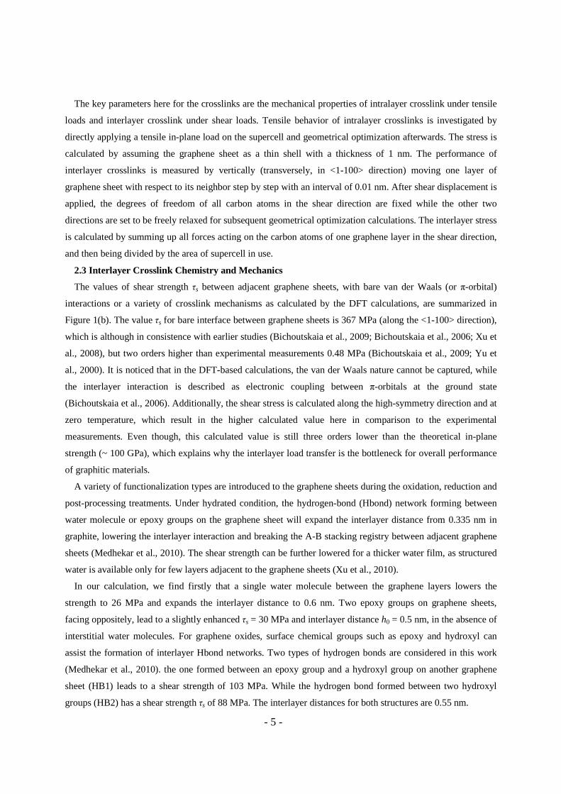
The key parameters here for the crosslinks are the mechanical properties of intralayer crosslink under tensile
loads and interlayer crosslink under shear loads. Tensile behavior of intralayer crosslinks is investigated by
directly applying a tensile in-plane load on the supercell and geometrical optimization afterwards. The stress is
calculated by assuming the graphene sheet as a thin shell with a thickness of 1 nm. The performance of
interlayer crosslinks is measured by vertically (transversely, in <1-100> direction) moving one layer of
graphene sheet with respect to its neighbor step by step with an interval of 0.01 nm. After shear displacement is
applied, the degrees of freedom of all carbon atoms in the shear direction are fixed while the other two
directions are set to be freely relaxed for subsequent geometrical optimization calculations. The interlayer stress
is calculated by summing up all forces acting on the carbon atoms of one graphene layer in the shear direction,
and then being divided by the area of supercell in use.
2.3 Interlayer Crosslink Chemistry and Mechanics
The values of shear strength τs between adjacent graphene sheets, with bare van der Waals (or π-orbital)
interactions or a variety of crosslink mechanisms as calculated by the DFT calculations, are summarized in
Figure 1(b). The value τs for bare interface between graphene sheets is 367 MPa (along the <1-100> direction),
which is although in consistence with earlier studies (Bichoutskaia et al., 2009; Bichoutskaia et al., 2006; Xu et
al., 2008), but two orders higher than experimental measurements 0.48 MPa (Bichoutskaia et al., 2009; Yu et
al., 2000). It is noticed that in the DFT-based calculations, the van der Waals nature cannot be captured, while
the interlayer interaction is described as electronic coupling between π-orbitals at the ground state
(Bichoutskaia et al., 2006). Additionally, the shear stress is calculated along the high-symmetry direction and at
zero temperature, which result in the higher calculated value here in comparison to the experimental
measurements. Even though, this calculated value is still three orders lower than the theoretical in-plane
strength (~ 100 GPa), which explains why the interlayer load transfer is the bottleneck for overall performance
of graphitic materials.
A variety of functionalization types are introduced to the graphene sheets during the oxidation, reduction and
post-processing treatments. Under hydrated condition, the hydrogen-bond (Hbond) network forming between
water molecule or epoxy groups on the graphene sheet will expand the interlayer distance from 0.335 nm in
graphite, lowering the interlayer interaction and breaking the A-B stacking registry between adjacent graphene
sheets (Medhekar et al., 2010). The shear strength can be further lowered for a thicker water film, as structured
water is available only for few layers adjacent to the graphene sheets (Xu et al., 2010).
In our calculation, we find firstly that a single water molecule between the graphene layers lowers the
strength to 26 MPa and expands the interlayer distance to 0.6 nm. Two epoxy groups on graphene sheets,
facing oppositely, lead to a slightly enhanced τs = 30 MPa and interlayer distance h0 = 0.5 nm, in the absence of
interstitial water molecules. For graphene oxides, surface chemical groups such as epoxy and hydroxyl can
assist the formation of interlayer Hbond networks. Two types of hydrogen bonds are considered in this work
(Medhekar et al., 2010). the one formed between an epoxy group and a hydroxyl group on another graphene
sheet (HB1) leads to a shear strength of 103 MPa. While the hydrogen bond formed between two hydroxyl
groups (HB2) has a shear strength τs of 88 MPa. The interlayer distances for both structures are 0.55 nm.
- 6 -
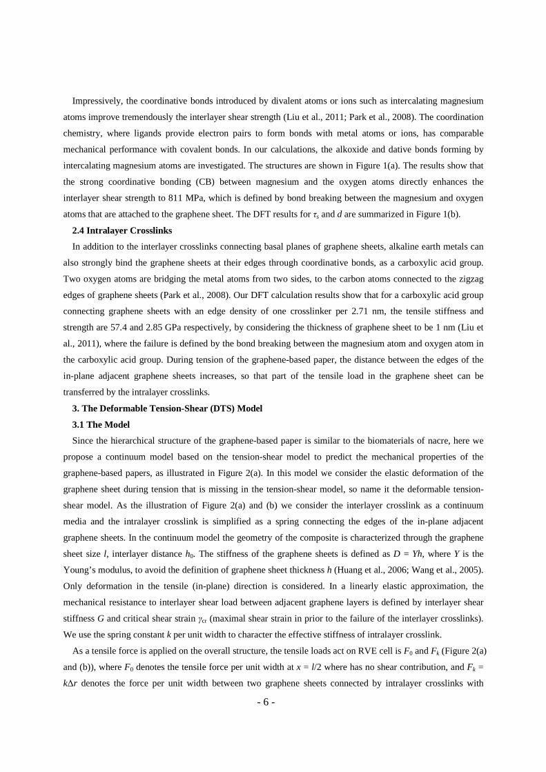
Impressively, the coordinative bonds introduced by divalent atoms or ions such as intercalating magnesium
atoms improve tremendously the interlayer shear strength (Liu et al., 2011; Park et al., 2008). The coordination
chemistry, where ligands provide electron pairs to form bonds with metal atoms or ions, has comparable
mechanical performance with covalent bonds. In our calculations, the alkoxide and dative bonds forming by
intercalating magnesium atoms are investigated. The structures are shown in Figure 1(a). The results show that
the strong coordinative bonding (CB) between magnesium and the oxygen atoms directly enhances the
interlayer shear strength to 811 MPa, which is defined by bond breaking between the magnesium and oxygen
atoms that are attached to the graphene sheet. The DFT results for τs and d are summarized in Figure 1(b).
2.4 Intralayer Crosslinks
In addition to the interlayer crosslinks connecting basal planes of graphene sheets, alkaline earth metals can
also strongly bind the graphene sheets at their edges through coordinative bonds, as a carboxylic acid group.
Two oxygen atoms are bridging the metal atoms from two sides, to the carbon atoms connected to the zigzag
edges of graphene sheets (Park et al., 2008). Our DFT calculation results show that for a carboxylic acid group
connecting graphene sheets with an edge density of one crosslinker per 2.71 nm, the tensile stiffness and
strength are 57.4 and 2.85 GPa respectively, by considering the thickness of graphene sheet to be 1 nm (Liu et
al., 2011), where the failure is defined by the bond breaking between the magnesium atom and oxygen atom in
the carboxylic acid group. During tension of the graphene-based paper, the distance between the edges of the
in-plane adjacent graphene sheets increases, so that part of the tensile load in the graphene sheet can be
transferred by the intralayer crosslinks.
3. The Deformable Tension-Shear (DTS) Model
3.1 The Model
Since the hierarchical structure of the graphene-based paper is similar to the biomaterials of nacre, here we
propose a continuum model based on the tension-shear model to predict the mechanical properties of the
graphene-based papers, as illustrated in Figure 2(a). In this model we consider the elastic deformation of the
graphene sheet during tension that is missing in the tension-shear model, so name it the deformable tension-
shear model. As the illustration of Figure 2(a) and (b) we consider the interlayer crosslink as a continuum
media and the intralayer crosslink is simplified as a spring connecting the edges of the in-plane adjacent
graphene sheets. In the continuum model the geometry of the composite is characterized through the graphene
sheet size l, interlayer distance h0. The stiffness of the graphene sheets is defined as D = Yh, where Y is the
Young’s modulus, to avoid the definition of graphene sheet thickness h (Huang et al., 2006; Wang et al., 2005).
Only deformation in the tensile (in-plane) direction is considered. In a linearly elastic approximation, the
mechanical resistance to interlayer shear load between adjacent graphene layers is defined by interlayer shear
stiffness G and critical shear strain γcr (maximal shear strain in prior to the failure of the interlayer crosslinks).
We use the spring constant k per unit width to character the effective stiffness of intralayer crosslink.
As a tensile force is applied on the overall structure, the tensile loads act on RVE cell is F0 and Fk (Figure 2(a)
and (b)), where F0 denotes the tensile force per unit width at x = l/2 where has no shear contribution, and Fk =
k∆r denotes the force per unit width between two graphene sheets connected by intralayer crosslinks with

- 7 -
extension ∆r, and F(x) (0 < x < l) is used to denote the tensile force distribution in the graphene sheet. The in-
plane displacements in the graphene sheet 1 and 2 are expressed as u1(x) and u2(x) respectively where x is the
position in the graphene sheet. Consequently, the shear stress in the interlayer continuum at position x is τ(x) =
G[u1(x) - u2(x)]/h0.
For graphene sheets 1 and 2 in one RVE (Figure 2(b)), the equilibrium equations are
( ) ( )( ) ( )
21
12
22
22
2 ,
2 .
u xD Gγ x
x
u xD Gγ x
x
∂=
∂∂
=∂
(1a)
As the shear strain in the interlayer continuums are γ1(x) = [u1(x) – u2(x)]/h0 and γ2(x) = [u2(x) – u1(x)]/h0, Eqs.
(1a) can be rewritten as
( ) ( ) ( )
( ) ( ) ( )
21 1 2
20
22 2 1
20
2 ,
2 .
u x u x u xD G
x h
u x u x u xD G
x h
∂ −=
∂
∂ −=
∂
(1b)
By solving these equations we obtain the general solutions of Eqs. (1b) as
1 2 1 2
1 2 3 40 0
( ) ( ) ,
( ) ( ) sinh cosh ,
u x u x A A x
x xu x u x A A
l l
+ = +
− = + (2)
with four undetermined parameters A1, A2, A3, A4, which can be determined through introducing boundary
conditions of graphene sheets 1 and 2 at x = 0 and x = l, where 00 4
Dhl
G= is a length parameter determined by
the graphene sheet stiffness and interlayer properties. For graphene sheet 1, at the left edge, i.e. x = 0, the
tensile force in the graphene sheet equals to the force in the intralayer crosslink spring
11
(0),
uD k r
x
∂= ∆
∂ (3a)
where ∆r1 is the extension of the intralyer crosslink and k is the spring constant. For graphene sheet 2, the
tensile force is F0
20
(0)uD F
x
∂=
∂. (3b)
Similarly, at the right edge, i.e. x = l, the tensile forces in graphene sheet 1 and 2 are
10
( )u lD F
x
∂=
∂, 2
2
( ),
u lD k r
x
∂= ∆
∂ (3c)

- 8 -
where ∆r2 is the extension of intralayer crosslink at the right edge of graphene sheet 2. The extension of
intralayer crosslinks can be determined by the displacements of neighboring graphene sheets, i.e. ∆r1 = u1(0) –
u2’(0) (Figure 2(c)) based on the assumption that the deformation in repeated RVEs is the same and u1’(0) –
u2’(0) = u1(l) – u2(l). The superscript ’ and ” represent the two repeated constructing cells of graphen sheet 1
and 2. In addition, the continuous condition leads to u1’(0) = u2(0) and we have ∆r1 = ∆r2 = u1(0) – u2 (0) + u1(l)
– u2(l).
3.2 The Impacts of Intralayer Deformation in the Graphene Sheet
Firstly we discuss the impacts of the elastic deformation of graphene sheets to the mechanical properties of
graphene-based paper. Thus here we neglect the intralayer crosslink that will be discussed later, i.e. by letting k
= 0 or Fk = 0. By letting the general solution (2) equal to the boundary equations (3) at x = 0 and x = l, we
obtain the four undetermined parameters, i.e. 0 0 0 0 0 02 3 4
0
(1 cosh / ), ,
sinh /
F F l F l l lA A A
D D D l l
+= = = and A1 is the rigid
body displacement no influence to the elastic deformation of RVE. The tensile force is calculated as 1uF D
x
∂=
∂,
and the tensile force distribution in one graphene sheet (0 < x < l) is
0
0 0
1[1 cosh( ) sinh( )],
2
F x c xF
l s l
+= − + (4)
where s = sinh(l/l0) and c = cosh(l/l0). The interlayer shear strain is γ1(x) = [u1(x) – u2(x)]/h0, correspondingly,
the shear strain distribution in the interlayer crosslink is
0 01
0 0 0
( ) [(1 )cosh( ) sinh( )] / ,F l x x
γ x c s sDh l l
= + − (5)
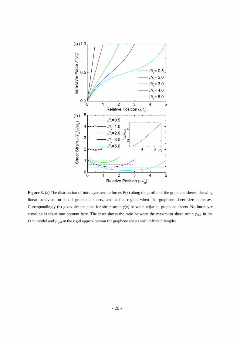
For graphene sheets with different lengths as l/l0 = 0.5, 1.0, 2.0, 3.0 and 5.0, we plot the distribution of in-
plane tensile force and interlayer shear strain along the length direction in Figure 3(a) and (b), respectively. We
can clearly see that at the open edge (x = 0), the tensile force is zero and at the midpoint of graphene sheet (x =
l), F = F0. Additionally, as l is small (l/l0 < 2), the force distribution function is linear along the graphene sheet
profile which is similar to the tension-shear chain model prediction. While as l/l0 reaches 5, the linearity is only
kept well when close to the edge of graphene sheets, i.e. x is close to 0 or l. In contrast, the central part of the
force distribution profile becomes flat, suggesting reduced load transfer through interlayer crosslinks. This is
also evidenced by the small shear strain amplitude in central part (x ~ l/2) of the crosslinks as plotted in Figure
3(b). Moreover, the maximal shear strain is reached at the edges of the graphene sheet, suggesting that the
failure of interlayer binding will be initialized there.
If the elastic deformation of the graphene sheets is not accounted for, i.e. the shear strain distribution along
the graphene sheets is uniform, for the given force F0 that is completely transferred by the two adjacent
interlayer shear (Figure 1(b)) we obtain the shear strain as γrigid = F0/(2lG). In order to compare with Eq. (5)
according to the definition of 00 4
Dhl
G= , the shear strain is written as

- 9 -
0 0 0rigid
0
2F l lγ
Dh l= . (6)
In Eq. (5) it is noticed that as the ratio l/l0 approaches 0, the term 0 0
[(1 )cosh( ) sinh( )] /x x
c s sl l
+ − (0 < x < l)
converges to a constant of 2l0/l, so that the Eq. (5) will degenerate into Eq. (6) and the DTS model is reduced
into the commonly used TS model. This situation could be arrived when the stiffness of interlayer crosslink is
much lower than that of the graphene sheet, or the size of graphene sheet is much smaller in comparison to l0.
For comparison, we further calculate the ratio between the maximum shear strain γmax in the DTS model and
γrigid in the rigid approximation for graphene sheets with different lengths
max
rigid 0
(1 )
2
γ l c
γ l s
+= . (7)
As shown in the inset of Figure 3(b), we find from Eq. (7) that as the size of the graphene sheet increases,
this ratio increases almost linearly, that means the elastic deformation of graphene has more impacts on the
overall mechanical properties of the whole material. As larger graphene sheets are able to stabilize the paper
structure and establish a uniform crosslink pattern, which further enhance the overall mechanical properties of
graphene-based papers, we must consider this elastic deformation in developing a continuum model to predict
these properties.
The parameter l0 characterizes a typical length scale for load transfer between adjacent graphene sheets
through interlayer crosslinks. As shown in Figure 3, the tensile load in the graphene sheets are mostly
transferred by the interlayer crosslink within the length of l0 from the edges of the graphene sheets. As the
maximum shear strain of the interlayer crosslink is reached at the edges of the graphene sheets, the strength of
the graphene-based papers is reached when the interlayer shear strain reaches the critical shear strain γcr of the
interlayer crosslink at the edges. Consequently, let x = 0 or x = l in Eq. (5) we obtain the relationship between
the critical shear strain and the tensile force as
0 0cr
0
1F l cγ
Dh s
+= . (8)
The maximal effective tensile stress F0/2h0, or strength σs in the RVE, is predicted as
( )cr
s0
.2 1
sγ Dσ
c l=
+ (9)
For the RVEs constructed by graphene sheets with different lengths, we plot their strength in Figure 4(a),
which shows that as l reaches 5l0, the strength value of the graphene paper converges to a constant value
γcrD/(2l0) . By substituting with 00 4
Dhl
G= , the upper bound strength can be written as cr 0
s0
2γ Glσ
h= . In the
tension-shear chain model, when the size of the rigid platelet is 2l0, the effective tensile strength of RVE is also
estimated as cr 0
0
2γ Gl
h when the whole interlayer materials reaches the same critical strain γcr. Because the

- 10 -
tensile load transferred by the interlayer shear deformation locates mainly within a distance of l0 from the
graphene edges, so the tensile strength is mainly contributed by the interlayer crosslinks in these regions. This
is the reason why the upper bound tensile strength of RVE constructed by very large size graphene sheets is
equivalent to the tensile strength of the RVE constructed by a rigid platelet with a length of 2l0 and the same
interlayer crosslink density. According to our first-principles calculations, we calculate the typical length scale
l0 for the magnesium coordinative crosslink is about 6.8 nm. While in graphene-based papers as synthesized by
current techniques, the size of graphene sheet is usually on the order from micrometers to millimeters, so the
elastic deformation of the graphene sheets has a strong impact on the overall mechanical properties and must be
accounted in order to make accurate predictions.
3.3 Effective Young’s Modulus and Toughness
We can also define an effective Young’s modulus Yeff for the whole structure as (F0/2h0)/(∆/l), where F0/2h0
is the effective tensile stress and ∆ = [u1(l) - u2(0)] is the elongation of the RVE cell. The effective Young’s
modulus is
eff00
11 122
DY
lchs l
=++
. (10)
Eq. (10) shows that Yeff scales linearly with l as it is small and converges to a constant Yeff = D/h0 for large
graphene sheets (l > 10l0), contributed solely by the tensile deformation in the graphene sheets, as shown in
Figure 4(a).
Toughness is the key material property to describe its ability to absorb energy and deform without fracturing.
Here in our graphene paper model, the toughness can be divided into two parts, i.e. the strain energy stored in
the in-plane tensile deformation of graphene sheet and the one in the shear deformation of the interlayer
crosslinks. According to the tensile force and the shear strain distribution as obtained in previous sections, we
now can directly calculate the tensile and shear energy in RVE as 2
02 d
2
l Fx
D∫ and 200
2 dlGγ h x∫ , respectively. So
the total strain energy density stored in both the graphene sheets and the interlayer crosslinks before material
failure, is calculated as
( )( )
0
20 cr 2 2
0
11
2 ,4 1
ls c
lT sh γ Dc l
+ +=
+ (11)
which has a maximum value of 0.178γcr2Dh0/l0
2 at l = 3.3 l0. For graphene sheets with different lengths we plot
the strain density of intralayer tensile contribution, interlayer shear contribution and their sum separately in
Figure 4(b). The results indicate that while the shear contribution decays as the graphene sheet size l increases
and becomes almost zero as l > 10l0, the tensile contribution has a maximum at l ~ 5l0 and converges to a
dominating contribution at large l values.
- 11 -
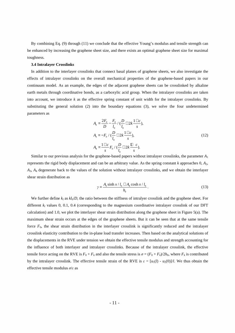
By combining Eq. (9) through (11) we conclude that the effective Young’s modulus and tensile strength can
be enhanced by increasing the graphene sheet size, and there exists an optimal graphene sheet size for maximal
toughness.
3.4 Intralayer Crosslinks
In addition to the interlayer crosslinks that connect basal planes of graphene sheets, we also investigate the
effects of intralayer crosslinks on the overall mechanical properties of the graphene-based papers in our
continuum model. As an example, the edges of the adjacent graphene sheets can be crosslinked by alkaline
earth metals through coordinative bonds, as a carboxylic acid group. When the intralayer crosslinks are taken
into account, we introduce k as the effective spring constant of unit width for the intralayer crosslinks. By
substituting the general solution (2) into the boundary equations (3), we solve the four undetermined
parameters as
0 02
0 0
3 00
4 00
2 1/ ( 2 ),
1/ ( 2 ),
1 1/ ( 2 ).
F F D cA k
D l l s
D cA F k
l s
c D cA F k
s l s
+= − +
+= − +
+ += +
(12)
Similar to our previous analysis for the graphene-based papers without intralayer crosslinks, the parameter A1
represents the rigid body displacement and can be an arbitrary value. As the spring constant k approaches 0, A2,
A3, A4 degenerate back to the values of the solution without intralayer crosslinks, and we obtain the interlayer
shear strain distribution as
3 0 4 0
0
sinh / cosh /γ
A x l A x l
h
+= . (13)
We further define kl as kl0/D, the ratio between the stiffness of intralyer crosslink and the graphene sheet. For
different kl values 0, 0.1, 0.4 (corresponding to the magnesium coordinative intralayer crosslink of our DFT
calculation) and 1.0, we plot the interlayer shear strain distribution along the graphene sheet in Figure 5(a). The
maximum shear strain occurs at the edges of the graphene sheets. But it can be seen that at the same tensile
force F0, the shear strain distribution in the interlayer crosslink is significantly reduced and the intralayer
crosslink elasticity contribution to the in-plane load transfer increases. Then based on the analytical solutions of
the displacements in the RVE under tension we obtain the effective tensile modulus and strength accounting for
the influence of both interlayer and intralayer crosslinks. Because of the intralayer crosslink, the effective
tensile force acting on the RVE is F0 + Fk and also the tensile stress is σ = (F0 + Fk)/2h0, where Fk is contributed
by the intralayer crosslink. The effective tensile strain of the RVE is ε = [u1(l) - u2(0)]/l. We thus obtain the
effective tensile modulus σ/ε as

- 12 -
eff0 0
1 11
1 2
1 1 1 11
1 12 1 2 1 2
12
l
l l
l
ccs k
sl c
c cl sks s
Y
k
k
D
h
+++
+−+
=
+ ++
+
+. (14)
For graphene sheets with different lengths, i.e. l/l0 = 0.5, 1, 3, 5, we plot the relationship between the
effective tensile modulus Yeff and the intralayer crosslink stiffness kl in Figure 5(b). As the stiffness of
intralayer crosslinks increases, the contribution of the in-plane tension of the graphene sheets also increases,
thus the effective tensile modulus of the RVE is enhanced. However, Yeff converges to D/h0, the same value as
the graphene papers without intralayer crosslinks, whenever kl and l increase.
As the maximum shear strain occurs at the edges of the graphene sheets, the failure firstly occurs at
interlayer crosslinks of the edge or intralayer crosslinks. Here to obtain some insights of the impacts from
intralayer crosslinks to the strength of the graphene-based papers we only consider the failure of the interlayer
crosslink. By equating the interlayer shear strain of edges with the critical strain of the interlayer crosslink, we
obtain the maximum allowable tensile force F0 is
norma0
0 cr0
l 2 l
h DF γ k
lF= + , (15)
where Fnormal is the maximum F0 without intralayer crosslinks. The other in-plane tensile force Fk loaded by
intralayer crosslink is
0cr
0
2k l
h DF γ k
l= . (16)
Finally we can obtain the strength of RVE accounting for both the intralayer and interlayer crosslink as
crcr normal
0
2 l
Dγσ σ k
l= + , (17)
where σnormal stands for the strength without intralayer crosslinks. From Eq. (17) we find that the influence of
the intralayer crosslink to the strength is 2klDγcr/l0, that is proportional to the stiffness of the stiffness kl of
intralayer crosslinks and independent on the graphene sheet size. In brief, the intralayer crosslink can enhance
both the modulus and strength of the graphene-based papers, where the enhancement effect of the modulus
improves for graphene sheets of small size, while for the strength there is no such size effects.
4. Discussion
4.1 Failure Mechanisms
When the applied load exceeds the strength, the whole composite starts to fail by breaking at the weakest
point, which could be at either the intralayer or interlayer crosslinks. For the first situation, the failure is
defined by that the displacement of intralayer crosslink exceeds ∆rcr. and for the second mechanism, it is
defined by the critical shear strain γcr of interlayer crosslinks. Correspondingly in our analytical model, if ∆rcr >
2hγcr, as in the situation where magnesium-based coordinative bonding crosslinks in-plane graphene sheets, the
failure of the structure starts at the interlayer crosslinks, initialized from the edge of the graphene sheets where

- 13 -
the shear strain distribution reaches its maximum (Figure 3(b) and Figure 5). On the other hand, if the intralayer
crosslinks break firstly and the elastic energy stored there is dissipated. As the second step, the load is then
sustained by interlayer crosslinks only, where material failure also starts from the edge of graphene sheets.
The failure of the interlayer crosslinks firstly occurs at the edges of the graphene sheets. Then as the failure
develops, the length of the interlayer crosslinks that are bearing loads decreases. However the effective load
transfer length is about l0, so that the strength reduction of the graphene-based papers is negligible if the
remaining length is larger than 3l0 (Figure 4). Because of this property the graphene-base papers can also bear
the load after the failure starts. This material robustness is of key importance in applications.
4.2 Optimal Design of the Mechanical Properties
By substituting all the mechanical parameters obtained from first-principles calculations to Eq. (3)-(5), we
plot the strength and toughness of three representative crosslink types in Figure 6(a). For graphite, where the
interlayer distance between graphene sheets is h0 = 0.335 nm, interlayer shear modulus G = 2.548 GPa and
maximum shear strain γcr = 0.144, the maximal strength and toughness are 6.3 GPa and 38 MPa respectively.
With the enhancement from Mg-centered coordinative bonds, G = 970 MPa, h0 = 0.71 nm and γcr = 0.76, thus
we have the shear strength approaching 14 GPa, and toughness of 400 MPa. While with the Hbond networks
formed between epoxy and hydroxyl groups, where G = 763 MPa, h0 = 0.545 nm and γcr = 0.135, the shear
strength and toughness are 2.5 GPa and 10 MPa. It is also noticeable that for all the structures, the toughness
maximizes for the graphene size at l ~ 23 nm. Furthermore we vary the shear modulus from 970 MPa to 97 and
9.7 MPa, and graphene sheet size from 100 nm to 1 nm to track their impacts on mechanical properties of the
graphene papers. Figure 6(b) shows that the strength changes from 10 MPa to 10 GPa and toughness changes
from 3 MPa to 400 MPa. Thus by increasing the graphene sheet size and crosslink strength, the strength and
toughness of the materials will be enhanced cooperatively.
Graphene-based paper, and in general nanocomposites, are projected for various applications requiring
ultrastrong, lightweight and multifunctional features. One additional benefit from interlayer crosslinks is that as
they are introduced, the interlayer distance is expanded. In comparison to metals such as aluminum with a mass
density 2.7 g/cm3, the density of graphite, 2.25 g/cm3, is already lower. For the coordinative bonds as an
example, the expansion due to coordinative bond will further lower the density approximately by half.
4.3 Additional Comments on the Crosslink Mechanisms
In order to improve the overall properties (stiffness, strength and toughness) of graphene-based
nanocomposites, three requirements must be fulfilled. (1) As the graphene sheets usually have finite size of
micrometers, an effective way to increase intralayer integration is needed to transfer the in-plane tensile load.
(2) Due to the randomness in distribution of graphene sheet sizes, positions and stacking orders, the load
transfer between adjacent graphene layers must be enhanced by introducing interlayer bridging. (3) The
crosslink between graphene sheets needs to be able to re-associate after breaking under tensile or shear loads.
The intralayer and interlayer crosslinks ensures a high toughness by utilizing the concept of ‘sacrificial bonds’
in biological materials such as bones (Ritchie et al., 2009). Especially the interlayer crosslinks can form again
after breaking and relative sliding between adjacent graphene layers. One interesting observation in Park et al.’s

- 14 -
report (Park et al., 2008) is that repeated cyclic loading of a metal-modified paper sample with small force and
under slow rate may allow for chemically annealing to the best crosslink structure. Thus the formation and
adjustment of crosslinks under loads, which could lead to ordering of the hierarchical structures, are of critical
importance for the mechanical properties enhancements of these nanocomposites. To fulfill requirements (1)
and (2), strong bonding like covalent and coordinative bonds take the advantage. However for (3), the covalent
bond, that is short-ranged and directional, is difficult to form again after breaking. The coordinative bonds
could play a critical role in the scenario with the presence of metal ions, epoxy and hydroxyl groups on
graphene oxide sheets (Liu et al., 2011). On the other hand, although the hydrogen bonds and van der Waals
forces are much weaker, they could provide remarkable mechanical contributions as working cooperatively.
5. Conclusions
In summary, the mechanics of graphene-based papers where graphene sheets are assembled in a layer-by-
layer manner is studied here by first-principle calculations and the deformable tension-shear model. In
comparison to the tension-shear chain model, we further include the elastic deformation of the graphene sheets
that has key impacts to the overall mechanical properties of the graphene-based papers, as evidence here by the
calculations and discussion. This model can also be extended to other paper-, fiber- or bundle-like materials
such as those of carbon nanotubes. According to the analysis results obtained from the DTS model, we find that
by simultaneously tuning the graphene sheet size and crosslink mechanisms, an optimal design of graphene-
based papers can be established with well-appreciated mechanical performance. This design concept is
reminiscent of many nature materials such as bones and mollusk shells (Fratzl et al., 2004; Ji and Gao, 2004),
where hierarchical structures are utilized and optimized for billions of years to fit requirements in enabling
biological functions. While in engineering for best mechanical performance, we here can simply pick the
strongest two-dimensional materials – graphene as show here and further engineer the crosslink mechanisms
between them, towards a supermaterial.
The results and model presented in this work directly map the atomistic level interactions into macroscopic
mechanical performance, and thus offer a rational design strategy for high-performance nanocomposites. To
characterize structural complexities such as the random distribution of graphene sheet sizes, positions, stacking
orders, crosslink density and strength, and quantify their thermal and electrical properties, need to be explored
further (Hartmann and Fratzl, 2009; Zhang et al., 2010).
Acknowledgements
This work is supported by Tsinghua University through the Key Talent Support Program, and the National
Science Foundation of China through Young Scholar Grant 11002079 (ZX) and Key Program Grant 10832005,
the China 973 Program No. 2007CB936803, 863 Program No. 2008AA03Z302 (QZ). This work is also
supported by Shanghai Supercomputer Center of China.
- 15 -
References Ajayan, P.M., Tour, J.M., 2007. Materials science: Nanotube composites. Nature 447, 1066-1068.
Bai, H., Li, C., Shi, G., 2011. Functional composite materials based on chemically converted graphene.
Advanced Materials 23, 1089-1115.
Barthelat, F., Tang, H., Zavattieri, P.D., Li, C.M., Espinosa, H.D., 2007. On the mechanics of mother-of-pearl:
A key feature in the material hierarchical structure. Journal of the Mechanics and Physics of Solids 55, 306-337.
Bichoutskaia, E., Ershova, O.V., Lozovik, Y.E., Popov, A.M., 2009. Ab initio calculations of the walls shear
strength of carbon nanotubes. Technical Physics Letters 35, 666-669.
Bichoutskaia, E., Heggie, M.I., Popov, A.M., Lozovik, Y.E., 2006. Interwall interaction and elastic properties
of carbon nanotubes. Physical Review B 73, 045435-045439.
Buehler, M.J., 2006. Nature designs tough collagen: Explaining the nanostructure of collagen fibrils.
Proceedings of the National Academy of Sciences 103, 12285-12290.
Ci, L., Suhr, J., Pushparaj, V., Zhang, X., Ajayan, P.M., 2008. Continuous carbon nanotube reinforced
composites. Nano Letters 8, 2762-2766.
Compton, O.C., Nguyen, S.T., 2010. Graphene oxide, highly reduced graphene oxide, and graphene: Versatile
building blocks for carbon-based materials. Small 6, 711-723.
Cox, H.L., 1952. The elasticity and strength of paper and other fibrous materials. British Journal of Applied
Physics 3, 72-79.
Dikin, D.A., Stankovich, S., Zimney, E.J., Piner, R.D., Dommett, G.H.B., Evmenenko, G., Nguyen, S.T., Ruoff,
R.S., 2007. Preparation and characterization of graphene oxide paper. Nature 448, 457-460.
Dunlop, J.W.C., Fratzl, P., 2010. Biological composites. Annual Review of Materials Research 40, 1-24.
Fratzl, P., Gupta, H.S., Paschalis, E.P., Roschger, P., 2004. Structure and mechanical quality of collagen-
mineral nano-composites in bone. Journal of Materials Chemistry 14, 2115-2123.
Fratzl, P., Weiner, S., 2010. Bio-inspired materials – mining the old literature for new ideas. Advanced
Materials 22, 4547-4550.
Gao, H., Ji, B., Jäger, I.L., Arzt, E., Fratzl, P., 2003. Materials become insensitive to flaws at nanoscale:
Lessons from nature. Proceedings of the National Academy of Sciences of the United States of America 100,
5597-5600.
Gao, X.L., Li, K., 2005. A shear-lag model for carbon nanotube-reinforced polymer composites. International
Journal of Solids and Structures 42, 1649-1667.
Gao, Y., Liu, L.-Q., Zu, S.-Z., Peng, K., Zhou, D., Han, B.-H., Zhang, Z., 2011. The effect of interlayer
adhesion on the mechanical behaviors of macroscopic graphene oxide papers. ACS Nano 5, 2134-2141.
Gong, L., Kinloch, I.A., Young, R.J., Riaz, I., Jalil, R., Novoselov, K.S., 2010. Interfacial stress transfer in a
graphene monolayer nanocomposite. Advanced Materials 22, 2694-2697.
Hartmann, M.A., Fratzl, P., 2009. Sacrificial ionic bonds need to be randomly distributed to provide shear
deformability. Nano Letters 9, 3603-3607.

- 16 -
Huang, X., Yuan, H., Liang, W., Zhang, S., 2010. Mechanical properties and deformation morphologies of
covalently bridged multi-walled carbon nanotubes: Multiscale modeling. Journal of the Mechanics and Physics
of Solids 58, 1847-1862.
Huang, Y., Wu, J., Hwang, K.C., 2006. Thickness of graphene and single-wall carbon nanotubes. Physical
Review B 74, 245413-9.
Jeong, H., Lee, Y.P., Lahaye, R.J.W.E., Park, M.H., An, K.H., Kim, I.J., Yang, C., Park, C.Y., Ruoff, R.S., H.,
L.Y., 2008. Evidence of graphitic ab stacking order of graphite oxides. Journal of American Chemical Society
130, 1362-1366.
Ji, B., Gao, H., 2004. Mechanical properties of nanostructure of biological materials. Journal of the Mechanics
and Physics of Solids 52, 1963-1990.
Ji, B., Gao, H., 2010. Mechanical principles of biological nanocomposites. Annual Review of Materials
Research 40, 77-100.
Kotov, N.A., 2006. Materials science: Carbon sheet solutions. Nature 442, 254-255.
Liu, Y., Xie, B., Xu, Z., 2011. Mechanics of coordinative crosslinks in graphene nanocomposites: A first-
principles study. Journal of Materials Chemistry 21, 6707-6712.
Medhekar, N.V., Ramasubramaniam, A., Ruoff, R.S., Shenoy, V.B., 2010. Hydrogen bond networks in
graphene oxide composite paper: Structure and mechanical properties. ACS Nano 4, 2300-2306.
Park, S., Lee, K.-S., Bozoklu, G., Cai, W., Nguyen, S.T., Ruoff, R.S., 2008. Graphene oxide papers modified
by divalent ions enhancing mechanical properties via chemical cross-linking. ACS Nano 2, 572-578.
Rafiee, M.A., Lu, W., Thomas, A.V., Zandiatashbar, A., Rafiee, J., Tour, J.M., Koratkar, N.A., 2010. Graphene
nanoribbon composites. ACS Nano 4, 7415-7420.
Rafiee, M.A., Rafiee, J., Wang, Z., Song, H., Yu, Z.-Z., Koratkar, N., 2009. Enhanced mechanical properties of
nanocomposites at low graphene content. ACS Nano 3, 3884-3890.
Ritchie, R.O., Buehler, M.J., Hansma, P., 2009. Plasticity and toughness in bone. Physics Today 62, 41-47.
Stankovich, S., Dikin, D.A., Compton, O.C., Dommett, G.H.B., Ruoff, R.S., Nguyen, S.T., 2010. Systematic
post-assembly modification of graphene oxide paper with primary alkylamines. Chemistry of Materials 22,
4153-4157.
Stankovich, S., Dikin, D.A., Dommett, G.H.B., Kohlhaas, K.M., Zimney, E.J., Stach, E.A., Piner, R.D.,
Nguyen, S.T., Ruoff, R.S., 2006. Graphene-based composite materials. Nature 442, 282-286.
Stankovich, S., Dikin, D.A., Piner, R.D., Kohlhaas, K.A., Kleinhammes, A., Jia, Y., Wu, Y., Nguyen, S.T.,
Ruoff, R.S., 2007. Synthesis of graphene-based nanosheets via chemical reduction of exfoliated graphite oxide.
Carbon 45, 1558-1565.
Tang, H., Barthelat, F., Espinosa, H.D., 2007. An elasto-viscoplastic interface model for investigating the
constitutive behavior of nacre. Journal of the Mechanics and Physics of Solids 55, 1410-1438.
Telling, R.H., Ewels, C.P., El-Barbary, A.A., Heggie, M.I., 2003. Wigner defects bridge the graphite gap.
Nature Materials 2, 333-337.

- 17 -
Wang, L., Zheng, Q., Liu, J.Z., Jiang, Q., 2005. Size dependence of the thin-shell model for carbon nanotubes.
Physical Review Letters 95, 105501-105504.
Xu, K., Cao, P., Heath, J.R., 2010. Graphene visualizes the first water adlayers on mica at ambient conditions.
Science 329, 1188-1191.
Xu, Z., Wang, L., Zheng, Q., 2008. Enhanced mechanical properties of prestressed multi-walled carbon
nanotubes. Small 4, 733-737.
Yu, M.F., Yakobson, B.I., Ruoff, R.S., 2000. Controlled sliding and pullout of nested shells in individual
multiwalled carbon nanotubes. Journal of Physical Chemistry B 104, 8764-8767.
Zhang, Z.Q., Liu, B., Huang, Y., Hwang, K.C., Gao, H., 2010. Mechanical properties of unidirectional
nanocomposites with non-uniformly or randomly staggered platelet distribution. Journal of the Mechanics and
Physics of Solids 58, 1646-1660.
Zhu, Y., Murali, S., Cai, W., Li, X., Suk, J.W., Potts, J.R., Ruoff, R.S., 2010. Graphene and graphene oxide:
Synthesis, properties, and applications. Advanced Materials 22, 3906-3924.

- 18 -
Figures and Captions
Figure 1. (a) A scanning electron microscopy (SEM) image of graphene oxide papers and an analytical model
showing the layered structures of graphene sheets, the intralayer and interlayer crosslinks. An atomic
representation of the bridging structure is also shown. (b) Shear strength and interlayer distance values between
adjacent graphene sheets that are bridged through several crosslink types, including bare interactions in
graphite, interstitial water layers (H2O), two epoxy groups (Epoxy), hydrogen bond networks formed between
epoxy and hydroxyl groups (HB1), two hydroxyl groups (HB2) and divalent atom assisted coordinative bonds
(CB).

- 19 -
Figure 2. The schematic illustration of the analytical model. Subplot (a) shows the overall paper structure and
representative volume element (RVE, as highlighted as the dash box) of the nano-composites. Subplot (b)
shows the continuum representation of interlayer crosslinks (defined as a continuum in yellow) and parameters
for geometry and mechanical properties, as used in the analytical model. Subplot (c) illustrates the load transfer
between graphene sheets.
- 20 -
Figure 3. (a) The distribution of intralayer tensile forces F(x) along the profile of the graphene sheets, showing
linear behavior for small graphene sheets, and a flat region when the graphene sheet size increases.
Correspondingly (b) gives similar plots for shear strain γ(x) between adjacent graphene sheets. No intralayer
crosslink is taken into account here. The inset shows the ratio between the maximum shear strain γmax in the
DTS model and γrigid in the rigid approximation for graphene sheets with different lengths.

- 21 -
Figure 4. (a) The strength and stiffness of graphene-based nanocomposites, described by the analytical model
developed in this work. The tensile strength converges quickly as the graphene sheet exceeds 5l0, and the
stiffness also converges but at a larger graphene sheet size l. (b) The toughness of the nanocomposite, which
reaches its maximum at 3.3l0. The toughness combines contributions from both intralayer and interlayer
elasticity. While the first one (in-plane tension) also has a peak at 5l0 and dominates for large graphene sheets,
the interlayer shear strain energy decreases as the graphene size increases.

- 22 -
Figure 5. (a) Shear strain distribution in the interlayer crosslinks along the graphene sheet including the
contribution of intralayer crosslinks, with spring constants k varying between 0.1D/l0 and 10D/l0. (b) The
relationship between the effective tensile modulus Yeff and the intralayer crosslink stiffness kl

- 23 -
Figure 6. (a) Dependences of strength and toughness of the two representative crosslink types (coordinative
bonds, CB and hydrogen bonds between epoxy and hydroxyl groups, HB1) and graphite. (b) The dependence
of tensile strength and toughness on interlayer shear modulus G and graphene sheet size l.
Related Documents