Polymer Composite Manufacturing Processes Introduc)on to Basic of Processing Techniques

Welcome message from author
This document is posted to help you gain knowledge. Please leave a comment to let me know what you think about it! Share it to your friends and learn new things together.
Transcript
Polymer Composite Manufacturing Processes
Introduc)on to Basic of Processing Techniques

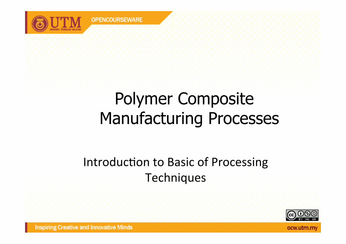
Reinforcement Shaping
Part Shape Definition
Matrix Infusion
Matrix Solidification
A variety of processes are in use, some very well developed, others relatively new, being the focus of current research.
When considering each process, think about the equipment required, and what important process parameters may need to be specified.
Reinforcement Shaping
Part Shape Definition
Matrix Solidification
Matrix Infusion
Continuous Processes: Product is generated continuously, passing through geographic stages
Batch Processes: Process stages occur sequentially in time to produce a single part
All processes can be roughly broken down into four important stages.
Introduction
Batch Processes
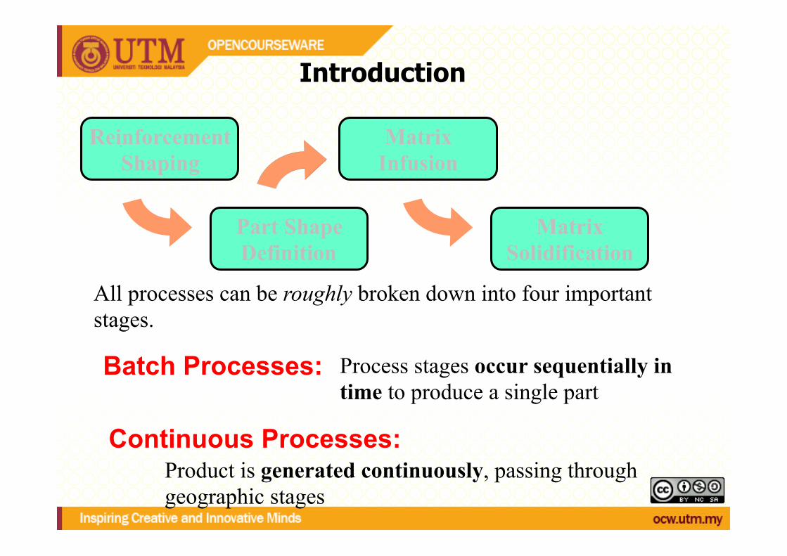
The stages that make up such manufacturing processes occur sequentially in time to produce a single part.
For batch processes, one major goal of process design is to reduce the cycle time required to produce a part.
These processes are usually completed on/in some form of mould.
E.g.
t1 t2 > t1 t3 > t2
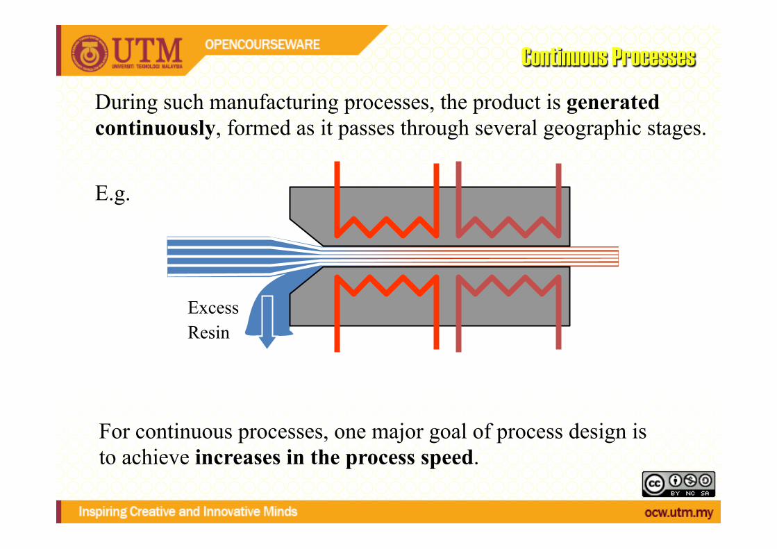
During such manufacturing processes, the product is generated continuously, formed as it passes through several geographic stages.
For continuous processes, one major goal of process design is to achieve increases in the process speed.
E.g.
Excess Resin!
Continuous Processes
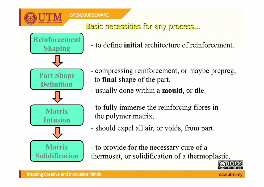
Basic necessities for any process...
- to provide for the necessary cure of a thermoset, or solidification of a thermoplastic.
Matrix Solidification
- to define initial architecture of reinforcement. Reinforcement
Shaping
- usually done within a mould, or die.
- compressing reinforcement, or maybe prepreg, to final shape of the part. Part Shape
Definition
- to fully immerse the reinforcing fibres in the polymer matrix. - should expel all air, or voids, from part.
Matrix Infusion

Composites manufacturing processes are complex, and involve combinations of the following physical processes;
1) The full potential of many techniques are yet to be reached.
2) There is scope to produce parts: • Faster, Cheaper, and with higher Quality.
Why spend significant effort studying, and analysing them?
1) Reinforcement Shaping
2) Resin Infusion
3) Composite Consolidation
4) Heat Transfer within Composite
5) Thermoset Cure Reaction
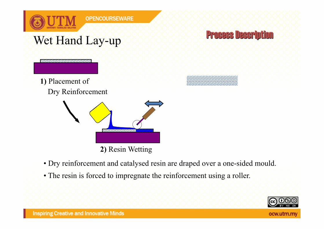
Wet Hand Lay-up Process Description
1) Placement of Dry Reinforcement
• Dry reinforcement and catalysed resin are draped over a one-sided mould.
2) Resin Wetting!
• The resin is forced to impregnate the reinforcement using a roller.
3) Repeated Application of Layers!
• A number of layers can be built up in sequence.
4) Resin Cure!
• Resin cure is initiated, and the part removed when sufficiently rigid.
Thermoset Manufacturing Processes

Wet Hand Lay-up
Part manufacture can be completed in several layers, with careful consideration of material compatibility, and sequential cure. Common modifications include:
Equipment
Vacuum bagging after lay-up
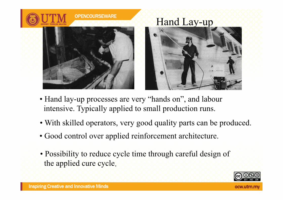
Hand Lay-up
• Hand lay-up processes are very “hands on”, and labour intensive. Typically applied to small production runs.
• Good control over applied reinforcement architecture. • With skilled operators, very good quality parts can be produced.
• Possibility to reduce cycle time through careful design of the applied cure cycle .
Hand lay-‐up n Advatages of Wet Lay-‐up
– Tooling can consist of any material that will hold its shape under minimal pressure. – Tooling can be changed easily for engineering changes. – Investment in pressure devices such as press, autoclave, or vacuum pump is not
required. The pump can improve the quality of parts. – Curing ovens are not needed
n Disadvantages of Wet Lay-‐up – Only addi)on-‐type cross-‐linking resin can be used, because condensa)on
polymeriza)on can cause bubbles and voids in part, which requires pressure. – Product is nonuniform and voids are common – Mechanical proper)es are low in comparison to other methods – Tight weave fabrics are difficult to saturate with high viscosity resins – Resin rich areas are common causing fracture points and shrinkage. – Only one finished surface
REINFORCING FIBER
n E-‐glass, S-‐glass, Aramid, Carbon/Graphite n E-‐glass most common (process inherently produces lower "quality"
composite laminate due to lack of )ght resin content control and low compac)on pressure)
n chopped mat material
– consists of randomly oriented chopped fibers or swirled con)nuous fibers which are held together loosely by a binder
n woven fabric material form most common
– available on rolls in widths from 36 in. to 60 in. typically
n unidirec)onal fabric – very fine filling (s)tching) yarn
RESINS
• polyesters • vinyl esters • epoxies

MOLD/TOOL PREPARATION
• procedure to some degree dependent on: – tooling material – whether tool is being used in first cycle or subsequent cycle
• clean tool – wipe with a clean cloth dampened with solvent (i.e. Acetone)
• mold release agents – waxes – spray releases – release films – internal releases (added to gel coat or resin system)
APPLYING A MOLD RELEASE AGENT
• apply release agent • allow period of time for release agent to
"set up" • Buff (polish) with clean cloth

THE WET LAY-‐UP PROCESS OFTEN BEGINS WITH A GEL COAT
• typically polyester, pigmented (different than mold colour), non-reinforced layer or coating
• produces decorative, high protective, glossy (shiny), coloured surface
• little or no additional finishing required • can paint on, roll on, or spray on • allow gel coat to set (gel)
CUTTING THE FABRIC
• cut desired pattern • tools: shears and/or utility knife

WEIGHING OUT THE RESIN
• weigh out resin components in specified proportions to achieve desired resin content (desired fiber volume of finished part) – epoxy curing agents expressed in parts per hundred by weight (phr) of
epoxy resin or parts by weight • EPON Resin 862/EPI-CURE 3274: 100/42
– resin content expressed as percent by weight • epoxy resins typically 25% - 35% by weight (dependent on ability to
wet out fiber, amount of resin bleeding out during cure, etc.) • need to account for process waste
– resin bleeding out, remaining on brushes, ...
• draw quantity of resin components, in separate containers • thoroughly mix resin components (combine resin into curing agent
container) • tools: containers, stirrers

RESIN SYSTEM QUANTITIES FOR THE DEMONSTRATION PART
• 16, 12 in x 12 in plies of 7781 E-glass cloth • resin system is Shell EPON Resin 862/EPI-CURE
3274 – (16 plies)(1 sq ft/ply)(1 sq yd/9 sq ft)(8.95 oz/sq yd)(1
lb/16 oz) = 0.994 lb – x/(x+0.994 lb) = 0.30 (x = lb of resin system) – x = 0.426 lb (193 gm) of resin system – EPON Resin 862 (100/(100 + 42))(0.426 lb) = 0.300 lb
(136 gm) – EPI-CURE 3274 (42/(100 + 42))(0.426 lb) = 0.126 lb
(57 gm) – account for process waste
APPLY RESIN TO FABRIC
• apply resin to fabric on mold surface or, preferably, wet out fabric with resin on separate surface and transfer to mold
• resin may be sprayed, poured or brushed on, and spread with brush and/or squeegee
• applying resin on mold surface prior to laying of fabric facilitates removal of entrapped air during compaction process - resin is forced up through the fabric along with the air
• tools: paint brush, spray equipment, squeegee

COMPACTION
• resin should be applied and compacted on mold surface from the center to the outside to facilitate removal of entrapped air, visually able to see air moving
• pressure can be applied with a squeegee and/or serrated roller
• bridging on female contours (radii) must be avoided
• tools: squeegee, serrated rollers

SPRAY-‐UP

WHAT IS SPRAY-‐UP?
• one or more continuous fiber rovings fed through a chopper
• fiber rovings are cut to predetermined lengths • chopped fibers are propelled into resin stream • resin and chopped fibers are deposited
simultaneously on mold • rolled by hand with serrated rollers • "automated wet lay-up" (however fibers not
continuous)

ADVANTAGES OF SPRAY-‐UP
• rapid lay-up • ability to fabricate large, complex shapes
where forming and fitting of mat or fabric would be difficult
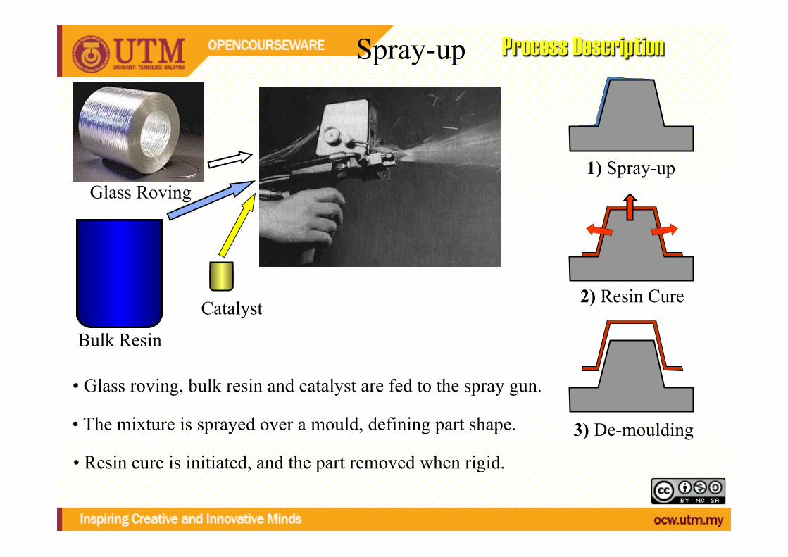
Spray-up Process Description
Glass Roving"
Bulk Resin"
Catalyst"
3) De-moulding
2) Resin Cure!
• Resin cure is initiated, and the part removed when rigid.
• Glass roving, bulk resin and catalyst are fed to the spray gun.
1) Spray-up
• The mixture is sprayed over a mould, defining part shape.

Spray-up Products & Equipment
Part being sprayed-up
Part removed from mould.
Full dispensing system
Chopper Roving
Atomised resin and catalyst
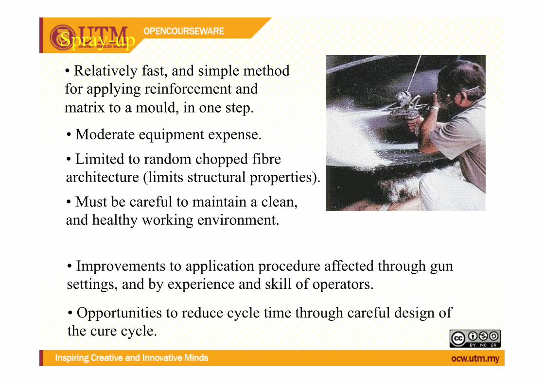
Spray-up • Relatively fast, and simple method for applying reinforcement and matrix to a mould, in one step.
• Moderate equipment expense.
• Must be careful to maintain a clean, and healthy working environment.
• Limited to random chopped fibre architecture (limits structural properties).
• Improvements to application procedure affected through gun settings, and by experience and skill of operators.
• Opportunities to reduce cycle time through careful design of the cure cycle.

REINFORCING FIBER AND RESIN SYSTEM
• E-glass roving • polyester resin – base resin (includes crosslinking agent,
usually styrene) – catalyst (initiator) – accelerator
SPRAY-‐UP SYSTEM COMPONENTS • pumps for resin and/or catalyst • pressure pots for catalysts • pressure pots for flushing solvents • chopper for fiber reinforcement • various air regulators and gauges for
control • various hoses for transporting materials • gun assembly for dispersing materials • compressed air source

RESIN SYSTEM MIXING METHODS
n external mix – resin/catalyst – resin and catalyst/resin and accelerator (two-‐pot system)
n internal mix – resin/catalyst (catalyst injec)on)
n air-‐atomized -‐ addi)on of air into the gun to disperse resin mix
n hydraulic pressure to disperse resin mix
CHOPPERS
• chops continuous fiber roving in lengths typically 1.5 - 5 mm.
• driven by small air motor, speed can be controlled by valves
• chopper comprised of two rollers – one made of rubber or urethane (cott wheel) – one made of aluminum with fitted slots to
hold razor blades (cutter wheel) – air motor drives either wheel with the roving
passing between the two wheels
FABRICATION PROCESS • if gel coat spray thin pass of resin (no chopped
roving) • usually start spray passes at bottom of mold
using horizontal spray pattern • overlap about one-third to assure uniform layer • follow horizontal layer with vertical layer, if
possible (will yield best uniform laminate) • gun head 18 - 24 in from the mold surface • most outputs and operators maintain 0.050 in
nominal thickness per pass
ADDITIONAL PROCESSING IS NEEDED AFTER CHOP IS APPLIED
TO MOLD • best laminate - one pass, roll out, let gel,
continue • rolled by hand with serrated rollers (aluminum or
plastic) to remove air, compact the fibers and smooth the surface
• start rolling near center and work to edges • male molds easier to spray-up and roll out,
however usually more fiber and resin overspray (waste) on floor
• cure will be similar to wet lay-up
Related Documents