POLYMER CAPACITORS VS. MLCCS MULTILAYER CERAMIC CAPACITOR POLYMER CAPACITORS – AN OPTIMAL REPLACEMENT FOR MLCCS WHITE PAPER VERSION 1.0 NO DC BIAS DC Bias Cap Change NO DERATING Time Capacitance NO SOLDER JOINT/CRACKING LONGER PREDICTABLE LIFETIMES

Welcome message from author
This document is posted to help you gain knowledge. Please leave a comment to let me know what you think about it! Share it to your friends and learn new things together.
Transcript

POLYMER CAPACITORS VS. MLCCS MULTILAYER CERAMIC CAPACITOR
POLYMER CAPACITORS – AN OPTIMAL REPLACEMENT FOR MLCCS
WHITE PAPER VERSION 1.0
NO DC BIASDC Bias
Cap C
hang
e
NO DERATINGTime
Capa
citan
ce
NO SOLDERJOINT/CRACKING
LONGER PREDICTABLELIFETIMES
2
PANASONIC POLYMER CAPACITORS VS. MULTILAYER CERAMIC CAPACITOR VERSION 1.0
industry.panasonic.eu
INTRODUCTION . . . . . . . . . . . . . . . . . . . . . . . . . . . . . . . . . . . . . . . . . . . . 3
POLYMER CAPACITORS AS ALTERNATIVE TO MLCCS . . . . . . . . . . . . . . . 5
USER CASE . . . . . . . . . . . . . . . . . . . . . . . . . . . . . . . . . . . . . . . . . . . . . . 10
CIRCUIT EXAMPLE . . . . . . . . . . . . . . . . . . . . . . . . . . . . . . . . . . . . . . . . . 11
TABLE OF CONTENTS

3
PANASONIC POLYMER CAPACITORS VS. MULTILAYER CERAMIC CAPACITOR VERSION 1.0
industry.panasonic.eu
INTRODUCTION
Most often capacitor selection to the uninformed seems like a simple choice but the demands, challenges and expectations of modern electronics prove otherwise . As more electronic systems continue to be integrated into our automobiles, the need for capacitor technologies that deliver high reliability, long life, stable performance, low ESR and low cost continue to grow . Polymer capacitors have met these needs in the enterprise, commercial, con-sumer, medical, and aerospace segments for more than 15 years . But polymer technology has been challenged when it comes to meeting the AEC Q200 requirements . Today, these challenges are being overcome as polymer capacitor technology makes it entrance into the automo-tive segment . These changes are a direct answer to the new requirements capacitors have to fullfil . In order to exemplify lets take a look at e .g . DCDC converters and how their requirements have changed: While DCDC converters have been required to have high efficiency, low noise and miniaturization, one of recent additional requirements is faster transient response characteristics to the load change . This is because ICs, etc . have been developing into the directions of higher speed, larger cur-rent and lower voltage operation . These achievements of the semiconductor industry have set trends in current and future electronic devices: Efficient power consump-tion, increasing load current, miniaturization and higher switching frequencies . IC operation of the high-speed and large current comes to increase variations in current load, and the low voltage operation comes to require very accurate stability in voltage . All of them require faster transient response for the converter to support the ICs . These trends entail capacitors that can cope with higher current loads while at the same time the available volume is decreasing . Electric engineers find themselves more and more confronted with the task to balance between high performance & power density vs . long term endur-ance, high reliability & safety .
The selection of a suitable output/input capacitor plays an important part in the design of switching voltage con-verters . “Some 99 percent of so-called ‘design’ problems associated with linear and switching regulators can be traced directly to the improper use of capacitors”, states
the National Semiconductor IC Power Handbook .
“Polymer capacitors offer higher capacitance values than MLCC capacitors”
The importance of the output capacitor in switching DCDC converters is related to the fact that it is (together with the main inductor) the reservoir of electric energy flowing to the output and it smoothes the output voltage . Some important considerations for input capacitors used in DCDC converters are the power dissipation and ripple performance . To maintain the voltage and to make sure the rail voltage is stable to the converter, an input capac-itor is required .
Various capacitor types can be used in the input and out-puts of DCDC converters . Table 1 shows various kinds of capacitor including electrolytic capacitors, OSCON, SP-Cap, POS-Cap, film capacitor, and multilayer ceramic ca-pacitors (MLCC), and ranks their performance according to each characteristic . The application typically dictates the best choice of capacitor type (MLCC, aluminum elec-trolytic, polymer, or tantalum) to use in the design . But before we get to that, generally speaking, following differ-entiation can be made: while electrolytic capacitors pro-vide the largest ESR these capacitors suffer significant degradation in capacitance and leakage current at higher temperatures and frequencies . Ceramic capacitors have a very low ESR and ESL that makes them great for tran-sient performance but they have limitations on capac-itance derating . Though ceramic capacitor can operate at very high ripple currents, they suffer the non-graceful aging failure and require lower operating electric fields . Polymer electrolytic capacitors are mainly used in power supplies of integrated electronic circuits as buffer, bypass and decoupling capacitors, especially in devices with flat or compact design . Thus they compete with MLCC ca-pacitors, but offer higher capacitance values than MLCC, and they display no microphonic effect (such as class 2 and 3 ceramic capacitors) .

4
PANASONIC POLYMER CAPACITORS VS. MULTILAYER CERAMIC CAPACITOR VERSION 1.0
Capacity
Temp Characteri-
stic
DC bias Characteri-
sticVoltage Range Size ESR Ripple
Electrolyte
OSCON
SP-Cap
POS-Cap
MLCC
very good good medium bad
industry.panasonic.eu
Table 1
MLCCs capacitors are by far the most widely used ca-pacitor type in DCDC converter input and output filters, due to their earlier mentioned low ESR, low ESL and low costs . So does this mean the equation is: no capacitor next MLCC when it comes to DCDC converters? It is not that easy as it might seem, especially since there are still some downsides to be considered when it comes to us-ing these capacitor in DCDC converters:
> Small capacitance per volume, especially for class 1 dielectric materials (NO/COG)
> Large body sizes prone to cracking with PCB flex > DC bias instability > Piezo-Effect (singing)
This is where polymer capacitors come into play . Panasonic is a leading manufacturer of Solid Polymer Aluminum Capacitors: SP-Caps and OS-CON, Tantalum Polymer Capacitor – POS-CAP as well as Polymer Hybrid Aluminum Electrolytic Capacitor technologies and has the longest design-in expertise and experience on the market . Conductive polymer aluminum solid capacitors, abbreviated to “polymer capacitors” in the following, have been extending in their application . The polymer ca-pacitor (as well as conventional aluminum electrolytic ca-pacitors) are featured by large capacitance and excellent bias characteristics which multilayer ceramic capacitors can never compete with . In addition to these advantag-es polymer capacitors have extremely low ESR charac-teristics . Regarding ESL, which is determined by inside structure and terminal configuration of the capacitors, by making structural improvements, the polymer capacitors have low ESL . Also concerning the dry-out of electro-lyte in service life and the changes of characteristics at a range of low temperatures the polymer capacitors have realized very high reliability and superior low temperature characteristics by using solid polymer materials as an electrolyte .
“The polymer capacitor are fea-tured by large capacitance and excellent bias characteristics”

5
PANASONIC POLYMER CAPACITORS VS. MULTILAYER CERAMIC CAPACITOR VERSION 1.0
industry.panasonic.eu
POLYMER CAPACITORS AS ALTERNATIVE TO MLCCS
Especially the SP-CAPs and POS-CAPs with their small size factor and cubical form are the go to products when it comes to the replacement of MLCCs . By looking closer at the characteristics of these different technologies once can see some major differences between them .
Stable vs. Frequency
Stable Capacitance: Figure 1 below shows the change in capacitance over a wide frequency range for different technologies . It clearly shows that polymer capacitors exhibit very similar performance to multi-layer ceramic capacitors .
Capacitance Density / Stability vs. DC Bias
Looking at the results in figure 1 may rise the question why should somebody switch to polymer technology . The answer for this questions is: MLCCs cannot achieve the same high capacitance as polymer for the same given footprint and volume . Secondly, the MLCC exhibits strong capacitance dependence on DC bias due to ferroelectric dielectic materials used for MLCCs . High-capacity, mul-tilayer ceramic capacitors have a property often not well understood by electronic designers i .e . stability and re-liability require extensive whetting . The capacitance of these devices varies with applied DC voltage which can lead to a capacity drop of more than 70% compared to the given specs on the data sheet . For polymer capacitors the capacitance does not vary significantly when the ap-plication voltage changes (compare figure 2) .
This advantages allow a significant lower part count us-ing SP-CAPs or POSCAPs instead of MLCCs, which not only safes space on the PCB but also is a cost factor by saving costs on parts and reducing the production steps . Especially pertinent given supply issues with MLCC, a phenomenon observed from early 2017 and expected to last well into 2019 .
Figure 2Figure 1
0.1 10 100 1000 100001
50
100
150
Frequency [kHz]
Capa
citan
ce [u
F]
MLCCPolymerTantalum
0.01 1 10 1000100 100000.1
-58
-80
-35
10
-13
Time [h]
MLCC
C/C0
Polymer
“Capacitance for polymer capacitors does not vary signifi-cantly”

6
PANASONIC POLYMER CAPACITORS VS. MULTILAYER CERAMIC CAPACITOR VERSION 1.0
industry.panasonic.eu
Stability vs. Temperature
Figure 3 shows typical temperature characteristics . The curve changes for MLCCs in various ways within the tol-erance range of each product . For polymer capacitors the capacitance is growing in parallel to the temperature rise . The temperature characteristics of MLCCs differ ac-cording to the dielectric type but all of them suffer aging failure by exhibiting temperature dependency and require lower operating temperature . Ceramic capacitors are brit-tle and sensitive to thermal shock, so precautions need to be taken to avoid cracking during mounting, especially for high-capacitance large MLCCs . The typical tempera-ture range for ceramic capacitors is -40°C to 85°C or 125°C, wherein their capacitance varies about from +5% to -40% having the sweet spot around the low tempera-ture of 5 to 25°C . Polymer capacitors have great develop-ment potential to achieve higher ratings on density, field stress and temperature (yet currently limited to 125°C) due to their working mechanism and dielectric materials advancement, yet higher dielectric constant polymers en-able a high energy density .
Piezoelectric Effects Ceramic Chip Capacitor
Most dielectrics of ceramic capacitors exhibit a charac-teristic identified as piezoelectric effects that can cause unexpected signals in certain circuits . In some cases, the piezoelectric effect may result in the appearance of elec-trical noise . When an electric potential or field is applied on the surface of an MLCC causes a deformation at a frequency range from 20Hz-20kHz, it could be audible to humans . This is then called the MLCC acoustic noise or singing noise (compare figure 4) . A MLCC alone is in most cases not sufficient to generate problematic or disruptive Sound Pressure Level (SPL) . But soldered on a PCB board the MLCC generates a spring mass system, which increases or dampens the oscillations depending on the frequencies .
MLCC Polymer
Figure 4
-55 -35 -15 5 25 45 65 85
at 120Hz
105
-30
-20
-10
0
10
20
30
40
-40
Temperature [°C]
MLCC
Capa
citan
ce ch
ange
[%]
Polymer
“MLCCs suffer aging failure by exhibiting temperature dependen-cy”
Figure 3

7
PANASONIC POLYMER CAPACITORS VS. MULTILAYER CERAMIC CAPACITOR VERSION 1.0
industry.panasonic.eu
Robust
Cracks in ceramic surface mount technology (SMT) components limit assembly reliability and yields . These cracks manifest themselves as electrical defects: inter-mittent contact, variable resistance, loss of capacitance and excessive leakage currents . That is why MLCCs are exposed to different reliability tests including thermal shock, board flex (bending), and biased humididty tests, etc ., depending on the targeted applications . MLCCs are exposed to more than ten reliability test including thermal shock, board flex (bending), and biased humidity tests, etc ., depending on the targeted applications . Among the reliability tests, the board flex test evaluates the mechan-ical resistance to cracking when MLCCs are subjected to bending stress on the printed circuit board (PCB) that the MLCC is soldered on . The bending of PCB can occur fre-quently during/between manufacturing steps and during operation under temperature variations . Flex cracking is due to excessive circuit board flexure .
Figure 5
As for the causes of board flexure, there are various caus-es including problems during the manufacturing process, such as solder stress due to an inappropriate amount of solder, stress applied at the time of depaneling or screw fastening, or board flexure at the time of final assem-bly, in addition to drops, vibration, or thermal expansion during use . Ceramics are strong in compression but weak in tension . It is for this reason MLCC supplieres provide guidelinesfor buying out MLCC on PCB boards, often di-recting the MLCC caps not to be layed out at the edges of the board or to control the direction of MLCCchip along the length rather than the width when tension is expected at a certain point of the PCB . This limits and may require changes on the part of the design engineer before closing a PCB layout . Thus, when a soldered MLCC experiences excessive board flex, a crack is easily generated in the element (compare figure 5) . A flex crack can cause an electrical conduction between opposing internal elec-trodes . It is also possible that an fail open can progress to a fail short with continue product usage . If a crack on a capacitor element progresses to a short circuit failure, it may cause problems such as heat generation, smoking, or ignition; therefore, it is indispensable to take measures against them, particularly in equipment where reliability is essential .
NO SOLDERJOINT/CRACKING

8
PANASONIC POLYMER CAPACITORS VS. MULTILAYER CERAMIC CAPACITOR VERSION 1.0
industry.panasonic.eu
Safety
Most ceramic capacitors have a fairly high voltage rating . If the capacitor experiences a voltage between its termi-nals higher than its rated voltage, the dielectric may break down and electrons will flow between the thin metal lay-ers inside of the capacitor, creating a short . Luckily, most ceramic capacitors are built with a hefty safety margin and do not experience any sort of catastrophic failure (such as exploding) . However, the rule of thumb dictates that you should derate ceramic capacitors by 50%, which means that if you are expecting to have a maximum of 5V between the capacitor’s leads, then you should use a capacitor rated for 10V or more .
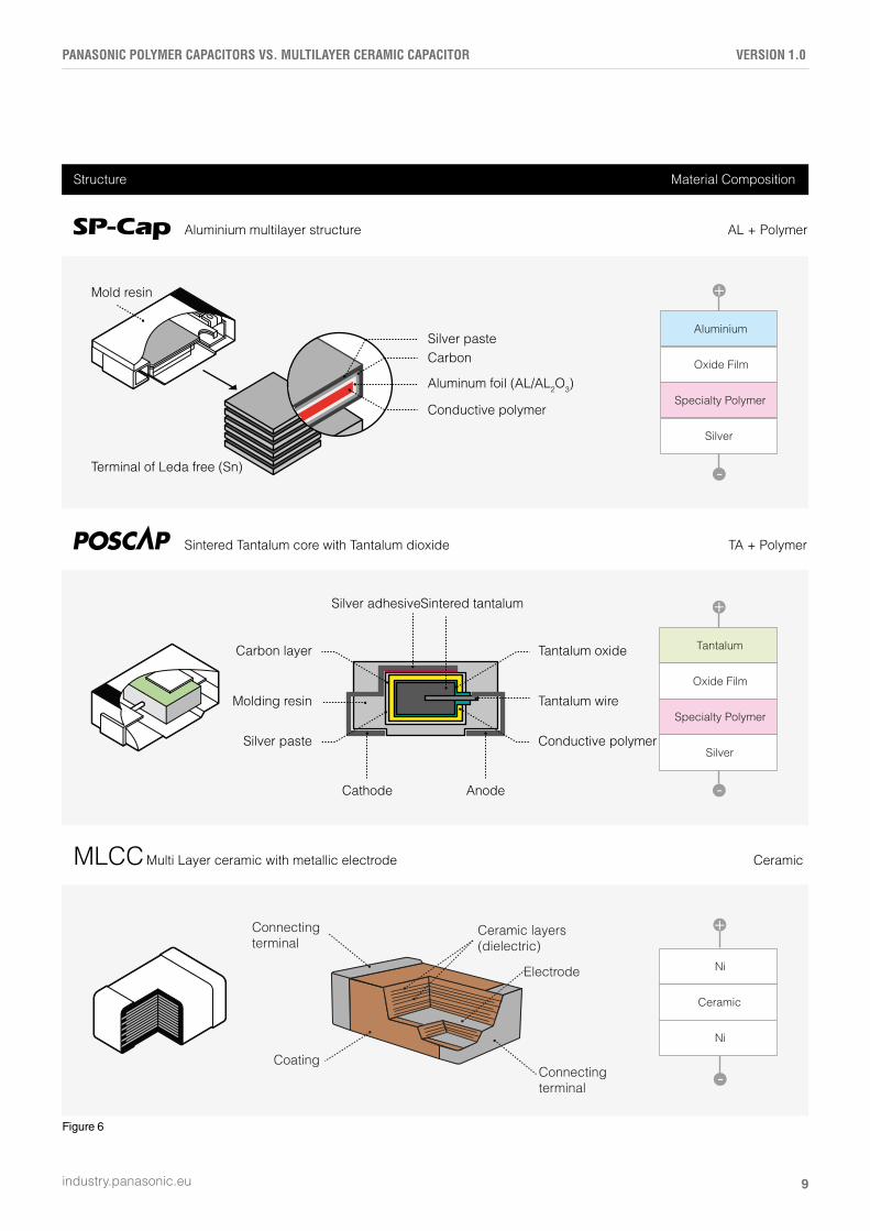
In order to understand the lifetime properties of poly-mer vs . MLCCs you have to take the construction and properties of each one into account (Please also com-pare figure 6 on the next page) . Polymer capacitors are coming as chip type or wound type products . Since sol-id polymer capacitors are not regarded as components which are likely to be replaced in a device, they are often made in SMT (Surface-Mount-Technology) . This allows them to take up less space on the PCB at the expense of being harder to unsolder if replacements are necessary . However, adopting SMT technology overall for a PCB also allows automated mounting, reducing costs and minimal human interference .
The use of solid electrolyte is a major advantage over electrolytic capacitors . In a wet electrolytic capacitor overheating can cause the electrolyte to evaporate . As it evaporates, pressure builds up within the capacitor and it may burst or even explode . Solid polymer capacitors don’t have such risks– the capacitor either shorts or starts acting like an open circuit towards the end of its lifetime . Generally speaking, the reliability of polymer ca-pacitors is much better than the reliability of electrolytic capacitors and particularly MLCCs .
9
PANASONIC POLYMER CAPACITORS VS. MULTILAYER CERAMIC CAPACITOR VERSION 1.0
industry.panasonic.eu
Figure 6
Aluminium multilayer structure AL + Polymer
TA + Polymer
Structure Material Composition
Sintered Tantalum core with Tantalum dioxide
CeramicMulti Layer ceramic with metallic electrodeMLCC
Aluminium
Oxide Film
Specialty Polymer
Silver
+
-
Tantalum
Oxide Film
Specialty Polymer
Silver
+
-
Ni
Ceramic
Ni
+
-
Carbon layer
Molding resin
Silver paste
Tantalum oxide
Tantalum wire
Conductive polymer
Silver adhesiveSintered tantalum
Cathode Anode
Silver pasteCarbon
Aluminum foil (AL/AL2O3)
Conductive polymer
Mold resin
Terminal of Leda free (Sn)
Coating
Ceramic layers(dielectric)
Electrode
Connecting terminal
Connectingterminal

10
PANASONIC POLYMER CAPACITORS VS. MULTILAYER CERAMIC CAPACITOR VERSION 1.0
industry.panasonic.eu
USER CASE
The comparison of the characteristics outlined above is only partial in nature . Each type of capacitor is well suited to some fields and poorly suited to others . When actually designing circuits it is necessary to consider a number of factors on addition to the characteristics described above, such as cost and size, on order to select the best capacitor for the job if space is limited, all-purpose MLCCs are the best . MLCCs are also suitable for appli-cations where the ability to deal with very high voltages is needed because of their high withstand voltage perfor-mance and ability to withstand reverse voltage . Typical polymer capacitors are a good choice when both, higher capacitance and low ESR are important . Especially the potential cost and space saving when comparing single polymer capacitors to an equivalent of multiple MLCCs can make a big different in designing PCBs .
Taking these considerations into account we define fol-lowing target specs for MLCC replacements with polymer capacitors:
> Voltage Lines: 16 to 35V > Capacitance: 47µF to 560µF
(and since large capacitance is THE strength of poly-mer capacitors – the higher the better)
> Preferably B & D case sizes
11
PANASONIC POLYMER CAPACITORS VS. MULTILAYER CERAMIC CAPACITOR VERSION 1.0
industry.panasonic.eu
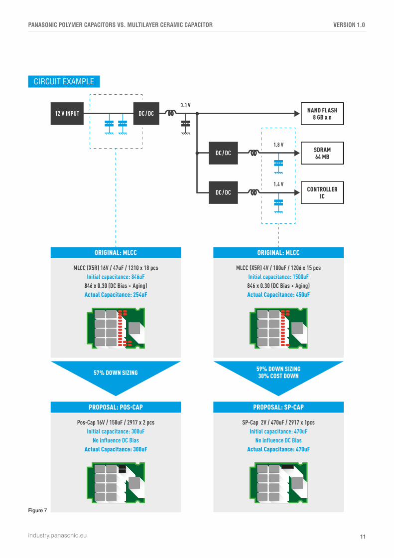
CIRCUIT EXAMPLE
Figure 7
NAND FLASH8 GB x n
SDRAM64 MB
CONTROLLERIC
DC / DC12 V INPUT
DC / DC
DC / DC1.8 V
1.4 V
3.3 V
MLCC (X5R) 16V / 47uF / 1210 x 18 pcsInitial capacitance: 846uF
846 x 0.30 (DC Bias + Aging)Actual Capacitance: 254uF
ORIGINAL: MLCC
Pos-Cap 16V / 150uF / 2917 x 2 pcsInitial capacitance: 300uF
No influence DC BiasActual Capacitance: 300uF
PROPOSAL: POS-CAP
57% DOWN SIZING
MLCC (X5R) 4V / 100uF / 1206 x 15 pcsInitial capacitance: 1500uF846 x 0.30 (DC Bias + Aging)Actual Capacitance: 450uF
ORIGINAL: MLCC
SP-Cap 2V / 470uF / 2917 x 1pcsInitial capacitance: 470uF
No influence DC BiasActual Capacitance: 470uF
PROPOSAL: SP-CAP
59% DOWN SIZING30% COST DOWN

WHITE PAPER VERSION 1.0
APRIL 2018
Panasonic Industry Europe GmbH
Robert-Koch-Strasse 100 · 85521 Ottobrunn · Germany
Internet: industry.panasonic.eu
Related Documents