Author's Accepted Manuscript Poly(brilliant green) and poly(thionine) mod- ified carbon nanotube coated carbon film electrodes for glucose and uric acid biosen- sors M. Emilia Ghica, Christopher M.A. Brett PII: S0039-9140(14)00525-6 DOI: http://dx.doi.org/10.1016/j.talanta.2014.06.068 Reference: TAL14890 To appear in: Talanta Received date: 22 April 2014 Revised date: 25 June 2014 Accepted date: 28 June 2014 Cite this article as: M. Emilia Ghica, Christopher M.A. Brett, Poly(brilliant green) and poly(thionine) modified carbon nanotube coated carbon film electrodes for glucose and uric acid biosensors, Talanta, http://dx.doi.org/10.1016/ j.talanta.2014.06.068 This is a PDF file of an unedited manuscript that has been accepted for publication. As a service to our customers we are providing this early version of the manuscript. The manuscript will undergo copyediting, typesetting, and review of the resulting galley proof before it is published in its final citable form. Please note that during the production process errors may be discovered which could affect the content, and all legal disclaimers that apply to the journal pertain. www.elsevier.com/locate/talanta CORE Metadata, citation and similar papers at core.ac.uk Provided by Estudo Geral

Welcome message from author
This document is posted to help you gain knowledge. Please leave a comment to let me know what you think about it! Share it to your friends and learn new things together.
Transcript
Author's Accepted Manuscript
Poly(brilliant green) and poly(thionine) mod-ified carbon nanotube coated carbon filmelectrodes for glucose and uric acid biosen-sors
M. Emilia Ghica, Christopher M.A. Brett
PII: S0039-9140(14)00525-6DOI: http://dx.doi.org/10.1016/j.talanta.2014.06.068Reference: TAL14890
To appear in: Talanta
Received date: 22 April 2014Revised date: 25 June 2014Accepted date: 28 June 2014
Cite this article as: M. Emilia Ghica, Christopher M.A. Brett, Poly(brilliantgreen) and poly(thionine) modified carbon nanotube coated carbon filmelectrodes for glucose and uric acid biosensors, Talanta, http://dx.doi.org/10.1016/j.talanta.2014.06.068
This is a PDF file of an unedited manuscript that has been accepted forpublication. As a service to our customers we are providing this early version ofthe manuscript. The manuscript will undergo copyediting, typesetting, andreview of the resulting galley proof before it is published in its final citable form.Please note that during the production process errors may be discovered whichcould affect the content, and all legal disclaimers that apply to the journalpertain.
www.elsevier.com/locate/talanta
CORE Metadata, citation and similar papers at core.ac.uk
Provided by Estudo Geral
Poly(brilliant green) and poly(thionine) modified carbon nanotube coated
carbon film electrodes for glucose and uric acid biosensors
M. Emilia Ghica, Christopher M.A. Brett*
Departamento de Química, Faculdade de Ciências e Tecnologia,
Universidade de Coimbra, 3004-535 Coimbra, Portugal
*Corresponding author: Tel: +351-239854470; Fax: +351-239827703
E-mail: [email protected]
�
Abstract
Poly(brilliant green) (PBG) and poly(thionine) (PTH) films have been formed on carbon film
electrodes (CFEs) modified with carbon nanotubes (CNT) by electropolymerisation using
potential cycling. Voltammetric and electrochemical impedance characterisation were
performed. Glucose oxidase and uricase, as model enzymes, were immobilised on top of
PBG/CNT/CFE and PTH/CNT/CFE for glucose and uric acid (UA) biosensing.
Amperometric determination of glucose and UA was carried out in phosphate buffer pH 7.0 at
-0.20 and +0.30 V vs. SCE, respectively, and the results were compared with other similarly
modified electrodes existing in the literature. An interference study and recovery
measurements in natural samples were successfully performed, indicating these architectures
to be good and promising biosensor platforms.
2��
Highlights
New redox polymer/carbon nanotube (CNT) based biosensors for
glucose and uric acid.
Poly(brilliant green) and poly(thionine) formed on CNT-modified C
film electrodes.
Performance of poly(brilliant green) superior to poly(thionine) based
biosensors.
Application to natural samples successful with good recoveries and no
interferences.
Keywords
Poly(brilliant green); Poly(thionine); carbon film electrodes; Carbon nanotubes; Glucose
oxidase; Uricase
1. Introduction
3��
The selection and development of active sensing materials for electrodes is a big challenge for
the construction of electrochemical biosensors. By using nanotechnology, a large number of
new materials and devices of desirable properties can be designed and it is possible to control
the fundamental properties of materials without changing the chemical composition. Complex
nanobiosensor architectures can aid in performing continuous monitoring as implantable
devices and in high throughput analysis such as lab-on-chip devices for rapid and low-cost
screening of physiological metabolites [1].
Carbon nanotubes (CNT) have been extensively used in recent years due to their low cost,
excellent chemical stability, good mechanical strength and electrical conductivity, good
electron transfer kinetics and biocompatibility [2]. CNT can improve electrochemical
properties, provide electrocatalytic activity and minimize electrode surface fouling, reasons
that make them excellent materials for the development of electrochemical sensors and
biosensors [3-5] generally leading to higher sensitivities and lower detection limits than
traditional electrode materials.
Conducting polymers (CP) have also been extensively studied as electroactive materials
during recent decades. Among them, redox dye polymers, especially phenazine derivatives,
have had many applications in sensors and biosensors e.g. [6-9].
CP/CNT nanocomposite modified electrodes have received significant interest because the
incorporation of conducting polymers into CNT can lead to new composite materials
possessing the properties of each component, with a synergistic effect that would be useful in
specific applications [10]. Carbon nanotubes can improve the conductivity of conducting
polymer matrices and form a three-dimensional network which can facilitate access to the
analyte and increase the rate of electron transfer [11].
The determination of both glucose and uric acid is of great clinical importance. Uric acid is
related to gout, cardiovascular and renal diseases, leukemia and pneumonia [12] and a high
4��
glucose level is associated with diabetes, which is related to complications to retina, the
circulatory system and kidneys [1]. New strategies based on different nanomaterials,
nanostructures or nanotechnologies for the development of biosensors have been explored for
the determination of these compounds; electrochemical ones often being preferred [1, 13-16].
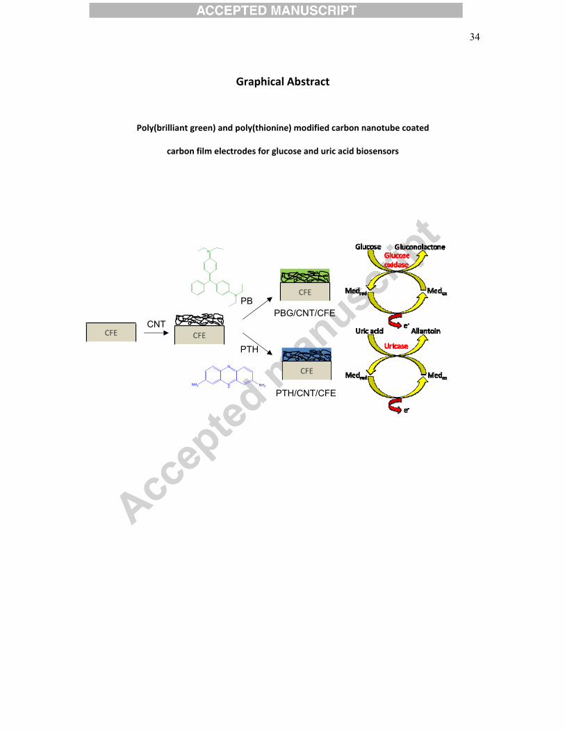
In the present work, nanostructured composites have been prepared by electropolymerisation
of brilliant green (BG) and thionine (TH), see Scheme 1, onto CNT-modified carbon film
electrodes (CFE). The modified electrodes PBG/CNT/CFE and PTH/CNT/CFE served as
platforms for the immobilization of glucose oxidase (GOx) and uricase (UOx) which were
used for sensing glucose and uric acid. To our knowledge, thionine monomer and carbon
nanotubes have been only used once to develop uric acid [17] and glucose [18] biosensors;
however, in both studies thionine was not polymerized and, in the case of glucose, the
biosensor also contained platinum nanoparticles. Regarding carbon nanotubes and
poly(brilliant green), there is no report up until now either for glucose, or for uric acid
determination. A comparison between the performances of the developed biosensors under
the same conditions was performed, the results are discussed with respect to other sensors in
the literature and natural samples are analysed.
2. Experimental
2.1 Reagents and solutions
All reagents were of analytical grade and were used without further purification. Glucose
oxidase (GOx, E.C. 1.1.3.4, from Aspergillus Niger, 24 U/mg), uricase (UOx, E.C. 1.7.3.3,
from Bacillus fastidiosus, 16.2 U/mg), phenol and Brilliant Green (BG) were acquired from
Fluka. �-D(+)-glucose, uric acid (UA), L-ascorbic acid (AA), glutaraldehyde (GA) (25% v/v in
water), bovine serum albumin (BSA) and urea were purchased from Sigma. Citric acid,
creatinine and ammonia were from Merck. Multi-walled carbon nanotubes (MWCNT) were
5��
from NanoLab, U.S.A., with ~95% purity, 30±10 nm diameter and 1-5 μm length. Chitosan
(Chit) of low molecular weight with a degree of deacetylation of 80 % and thionine (TH, dye
content 90%) were obtained from Aldrich.
All solutions were prepared using Millipore Milli-Q nanopure water (resistivity > 18 M�
cm). The supporting electrolyte for biosensors evaluation was sodium phosphate buffer saline,
NaPBS (0.1 M NaH2PO4/Na2HPO4 + 0.05 M NaCl), pH 7.0. For BG electropolymerisation,
universal buffer McIlvaine (0.1 M citric acid + 0.2 M Na2HPO4) pH 4.0 was used and for TH
polymerisation the buffer was sodium tetraborate (0.025 M Na2B4O7) + 0.10 M KNO3, pH
9.0.
2.2 Methods and instruments
All measurements were performed in a 15 mL, one-compartment, cell containing a carbon
film electrode (CFE) as working electrode, a platinum wire auxiliary electrode and a saturated
calomel electrode (SCE) as reference.
Voltammetric and amperometric experiments were carried out using a CV-50W Voltammetric
Analyser from Bioanalytical Systems, controlled by BAS CV-2.1 software.
The pH measurements were performed with a CRISON 2001 micro pH-meter. All
experiments were performed at room temperature, 25 ± 1 oC.
2.3 Carbon film electrode preparation and pre-treatment
The working electrodes were made from carbon film resistors (2 � nominal resistance, 15 μm
film thickness) of length 6 mm and 1.5 mm in diameter; the detailed preparation is described
elsewhere [19]. The cylindrical resistor, a carbon film pyrolitically deposited on a ceramic
substrate, has two tight-fitting metal caps, one at each end, linked to an external contact wire.
6��
In order to make the electrode one of them was removed and the other shielded in plastic and
protected by normal epoxy resin. The exposed geometric area of the electrodes is 0.20 cm2.
Since carbon film electrode surfaces cannot be renewed by polishing or other mechanical
methods, electrochemical pre-treatment was always performed before use in order to achieve
a reproducible electrode response. This consisted in potential cycling between -1.0 and +1.0 V
vs SCE, at 100 mV s-1, until a stable voltammogram was obtained.
2.4 Carbon nanotube functionalisation and deposition
Multi-walled carbon nanotubes (MWCNT) were purified and functionalised as previously
described [20]. A mass of 120 mg of MWCNT was stirred in 10 mL of a 5 M nitric acid
solution for 24 h, in order to cause partial destruction of the CNTs and introduce –COOH
groups at the ends and sidewall defects of the CNT [21]. The solid product was collected on a
filter paper and washed several times with nanopure water until the filtrate solution became
neutral (pH � 5). The functionalised MWCNT were then dried in an oven at 80 ºC for 24 h.
In order to prepare a 1.0 % w/v chitosan solution, 100 mg of Chit powder was dissolved in 10
mL of 1.0 % v/v acetic acid solution and stirred for 3 h at room temperature to ensure
complete dissolution. The chitosan solution was stored at 4 oC.
A 1.0 % w/v MWCNT solution was prepared by dispersing 3 mg of functionalised MWCNT
in 300 μL of 1.0 % w/v Chit in 1.0 % v/v acetic acid solution and sonicating for 3 h. For CNT
deposition a 10 μL drop of the 1 % w/v MWCNT solution was placed on the surface of the
CFE, left to dry in air at room temperature and this step was then repeated.
2.5 Brilliant green and thionine polymerisation
Poly(brilliant green) (PBG) and poly(thionine) (PTH) films were formed by
electropolymerisation using potential cycling.
7��
Prior to polymerisation of BG, the electrode was activated, as described in [22] for malachite
green, by cycling in 0.1 M sulfuric acid between -1.0 and +2.0 V vs SCE at 100 mV s-1 until a
stable voltammogram was obtained. Polymerisation of BG was carried out in an aqueous
solution containing 1 mM brilliant green in McIlvaine buffer, pH 4.0, sweeping the potential
between -1.0 and +1.2 V at a scan rate of 100 mV s-1 during 5 cycles [23] at CFE and 20
cycles at CNT/CFE.
For TH polymerisation, a solution of 0.025 M Na2B4O7 + 0.10 M KNO3, pH 9.0 and 1 mM
thionine was used. Polymerisation of thionine can occur from different media [24, 25]; these
studies point to a higher pH value for better film growth, as occurs with other phenothiazines
[26]. Potential cycling polymerisation was done between -1.0 and +1.0 V vs SCE at a scan
rate of 50 mV s-1 during 30 cycles at CFE and 40 cycles at CNT/CFE.
2.6 Enzyme immobilisation
A glucose oxidase solution was prepared by dissolving 10 mg GOx and 40 mg BSA in 1 mL
of 0.1 M NaPBS (pH 7.0). Each 10 μL of the previous solution was mixed with 5 μL of GA
(2.5% v/v in water) and from this mixture a volume of 10 μL was placed onto the previously
modified electrodes PBG/CNT/CFE or PTH/CNT/CFE. The uricase solution was prepared by
dissolving 5 mg of UOx in 1 mL of 0.1 M NaPBS (pH 7.0) and then placing 10 μL of this
solution onto the carbon nanotube/polymer modified electrodes. When not in use, enzyme
electrodes were kept in phosphate buffer electrolyte, pH 7.0 at 4 ºC.
8��
3. Results and Discussion
3.1 Carbon nanotube/polymer deposition and characterisation
Among the preparation methods of polymer/nanotube composites, a simple one and maybe
the most used is polymerisation of the corresponding monomer after modification by carbon
nanotubes [27-29].
Poly(brilliant green) and poly(thionine) were deposited by potential cycling onto carbon film
electrodes or on CFE modified with carbon nanotubes; cyclic voltammograms obtained
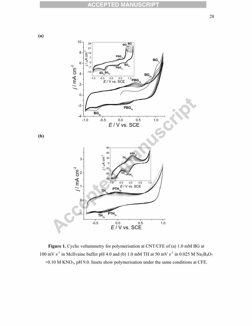
during polymerisation are shown in Figure 1. For Brilliant Green at CFE, Fig. 1a inset, three
oxidation and four reduction peaks were observed. At high positive potentials, ~1.0 V vs
SCE, irreversible monomer oxidation occurs, BG1. At 0.8 V appears a redox couple
BG2a/BG2c. Since BG1 decreases in height with each cycle and BG2a increases, while BG2c
decreases, this couple can be associated with an intermediary form of partially oxidised
monomer [23] which is probably not very stable at this pH. The monomer reduction peak,
BG3c at CNT/CFE, appears as a double peak at CFE, probably due to the same intermediate
forms mentioned. With more cycles, these two peaks decrease in height and overlap, finally
transforming to one peak, similarly to CNT/CFE. The redox couple, PBG1a/PBG1c with
formal potential 0.37 V is due to polymer oxidation/reduction and its height increases with
each cycle, showing poly(brilliant green) growth.
Thionine polymerisation, Fig 1b, exhibited similar cyclic voltammograms at bare and carbon
nanotube modified carbon film electrodes. Monomer cation radical formation occurs close to
+1.0 V. Two redox couple are visible, the more negative one, midpoint potential -0.237 V at
CFE and -0.320 V at CNT/CFE is ascribed to monomer oxidation/reduction, TH1a/TH1c, and
the other, ~0.05 V at CFE and 0.115 V at CNT/CFE is due to oxidation and reduction of the
polymer, PTH1a/PTH1c. The monomer couple peaks decrease with each cycle, while those of
the polymer increase, indicative of poly(thionine) growth.
9��
The PBG film is deposited faster at CNT/CFE than PTH: peak currents increased up to 20
cycles for PBG, whereas for PTH, the film stopped growing only after 40 cycles. This can be
attributed to continued brilliant green monomer diffusion to all nucleation sites within the
CNT network on the surface (see Fig.2) as well as the increased surface area. At bare
electrodes (see insert of Figure 1) the polymerisation of brilliant green stops very quickly,
after 5 scans, whereas thionine continues to be polymerised up to 30 cycles.
The mechanism of polymerisation of brilliant green has been previously discussed [23] and
details concerning thionine polymerisation can also be encountered [30]. During
polymerisation, as observed in the cyclic voltammograms, as well as visually after
polymerisation, a better polymer film is formed by PTH on bare carbon film electrodes,
whereas at carbon nanotube modified carbon film electrode, PBG is better. This is probably
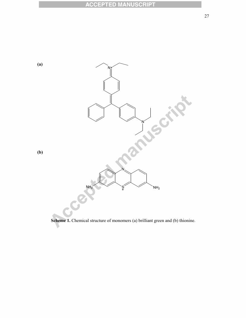
due to the more flexible chemical structure of the brilliant green monomer, as can be verified
in Scheme 1, compared with that of thionine, which makes entry of BG into the carbon
nanotube structure easier. In both cases the polymer redox couple current peaks increased
greatly in the presence of nanotubes. This effect can be attributed to the large number of
defects and spatial nanostructure of nanotubes that can act as a molecular wire and enhance
electron transfer [30].
The modified electrodes PBG/CFE, PTH/CFE, PBG/CNT/CFE and PTH/CNT/CFE were
characterised by cyclic voltammetry (CV), electrochemical impedance spectroscopy (EIS)
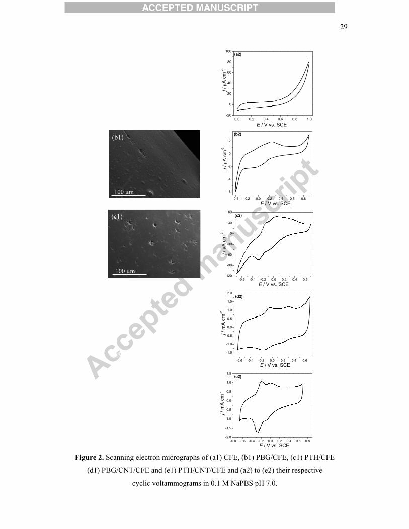
and scanning electron microscopy (SEM). The scanning electron micrographs showed similar
morphologies for the polymer modified electrodes (Figure 2b1 and 2c1) and the unmodified
electrode (Fig. 2a1), meaning that the covering layer is very thin. The presence of peaks in
cyclic voltammetry (Fig. 2b2 and 2c2) indicates the presence of some polymer on the bare
carbon film electrode. Regarding the CNT-modified electrodes, the electrode surface is
uniformly covered by the nanotubes and the two polymers grow in different ways on them. In
10��
the case of thionine, which has a more planar structure, the polymer covers the CNT surface,
PTH growing over the nanotubes, forming a distinct and rough layer, as can be observed from
the thick structures formed on top of CNT in Figure 2e1. On the other hand, brilliant green, a
more flexible molecule, can enter inside the nanotubes and form a nanostructured composite,
as discussed above for the electropolymerisation CVs: more homogeneous and thinner
structures above are observed in Figure 2d1.
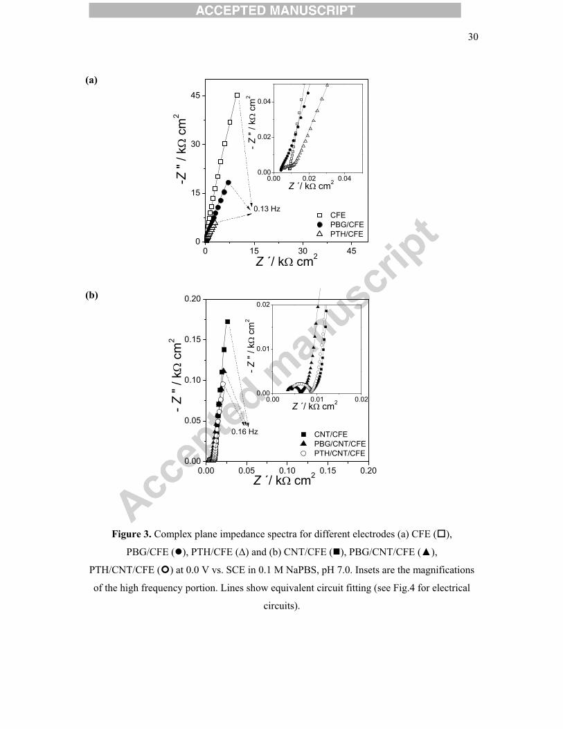
Impedance spectra recorded at 0.0 V versus SCE for bare carbon film electrodes, carbon
nanotube, polymer and carbon nanotube/polymer modified electrodes are shown in Figure 3.
All spectra, except at the bare electrode, present a semicircle in the high frequency region,
corresponding to the electron transfer process, and a linear low frequency region, due to
diffusion. The bare electrode spectrum shows only the linear part, consistent with no electron
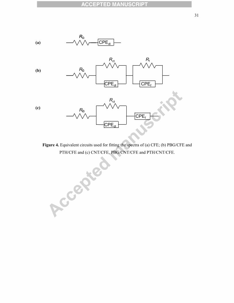
transfer occurring at this potential. The generic electrical circuit used to model the spectra
consists of a cell resistance, R�, in series with a parallel combination of a charge transfer
resistance, Rct, and a constant phase element, CPEdl, representing the electrode/solution
interface, this in series with a parallel combination of a resistance, Rf, and a second constant
phase element, CPEf, representing the film. Only polymer modified electrodes required
inclusion of Rf (Fig. 4b) in the equivalent circuit and for bare electrode the circuit consisted
only of R� and CPEdl (Fig.4a). The constant phase elements are modelled as non-ideal
capacitors and are described by CPE = -(i�C)-�, where � is the angular frequency and � the
CPE exponent, reflecting a non-uniform surface.
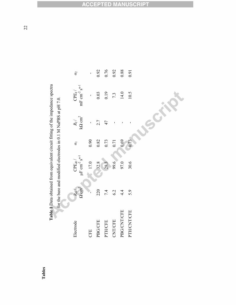
Calculated values of the circuit parameters are shown in Table 1. The values of R� were
between 4-8 � cm2, the Rct value is much higher for PBG/CFE compared with that for
PTH/CFE, which is in agreement with lower currents in cyclic voltammetry, since less
polymer was deposited. Moreover, at the potential studied, 0.0 V, only a small redox activity
11��
of PBG is observed. On the other hand, the film resistance Rf, is smaller for PBG, and this
might be related to faster diffusion of counterions through this film.
The value of the charge transfer resistance decreased when the electrodes were modified by
nanotubes, corresponding to easier electron transfer. A further small decrease was observed
with addition of polymers, meaning that the rate of electron transfer is mainly dictated by the
nanotubes. In the presence of CNT, the value of Rct is smaller for the PBG/CNT modified
electrode, meaning that electron transfer is easier and suggests that PBG is more easily
deposited on the CNT than is PTH; as found below in the application as biosensor, this
modified electrode shows a better performance. The double layer capacitance, expressed as
CPEdl, is higher for modified electrodes than bare, while �1 decreases, due to the less uniform
surface. With CNT and polymer/CNT, the values are much higher and with similar values of
�1. The CPEdl value for PBG/CNT/CFE is similar to that of CNT/CFE, which corroborates
with what was stated above, that PBG is deposited within the CNT structure; hence, the
interface is more similar to CNT only. On the other hand the PTH/CNT/CFE and PTH/CFE
interfaces are alike, as reflected by the similar CPEdl values.
In the presence of CNT, the modifier layer offers no resistance, only charge separation, CPEf,
which value increases with each layer of modifier, being highest for PBG/CNT/CFE. This
confirms the results obtained by cyclic voltammetry where the highest capacitive currents
were observed for PBG/CNT/CFE, see Figure 2d2 and 2e2.
3.2 Glucose biosensor
The modified electrodes GOx/PBG/CNT/CFE and GOx/PTH/CNT/CFE were employed for
the determination of glucose by fixed potential amperometry. The effect of applied potential
on the current response as a function of glucose concentration was studied. Amperometric
measurements were performed at potentials ranging from -0.20 to +0.10 V under continuous
12��
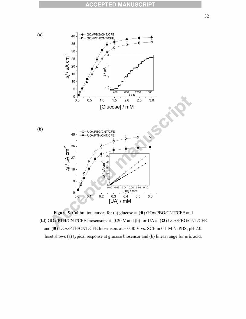
stirring, glucose being injected after baseline stabilisation. The results obtained are shown in
Figure 5a as calibration curves, �j corresponding to the change in current density. In the range
of applied potentials studied, anodic currents were observed at all potentials at both
GOx/PBG/CNT/CFE and GOx/PTH/CNT/CFE. It has been previously shown that binding of
glucose oxidase to high molecular redox polymer results in the establishment of direct
electrical communication between the redox centre of the enzyme and the electrode, different
polyphenazines exhibiting this behaviour [31, 32]. The mechanism proposed is similar to that
in [13, 28, 31], attributed to competition between FAD regeneration and hydrogen peroxide
reduction. For both electrodes the response decreases when moving to more positive
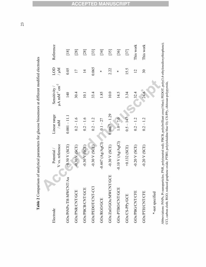
potentials; hence, the best choice was to determine glucose at -0.20 V vs. SCE. The analytical
parameters obtained are shown in Table 2 together with those of some recent, similar
biosensors in the literature.
Examination of Table 2 shows that the applied potential of the new biosensor is less negative
than many others previously reported [28, 33-35]. Although one biosensor has a much higher
sensitivity than that obtained here [18], based on thionine adsorbed on MWCNT, together
with platinum nanoparticles, that greatly enhance the response, it operates at a much higher
potential of +0.50 V vs. SCE. Biosensors based on a carbon film electrode modified with
poly(neutral red)/CNT [28] and on a poly(3,4-ethylenedioxythiophene)/CNT modified carbon
cloth electrode [33] showed similar sensitivities at -0.30 V vs. SCE; however, all the others
[28, 34-37] exhibited lower responses than the biosensor proposed here.
The storage stability of the biosensors was checked every 3 days over a period of one month
by performing a calibration curve consisting of 10 injections each time. When not in use, the
electrodes were kept in phosphate buffer at 4 ºC. In the case of the GOx/PBG/CNT/CFE
biosensor, a decrease of 18 % from the initial response was observed, whilst for
GOx/PTH/CNT/CFE the response dropped by 30 %. The reproducibility of the biosensors
13��
was assessed by comparing the sensitivity for 4 different electrodes prepared in the same way.
The relative standard deviation of the response (RSD) was 2.4 % for GOx/PBG/CNT/CFE
and 4 % for GOx/PTH/CNT/CFE indicating a reproducible fabrication method. Similarly, to
evaluate the repeatability of the biosensors, the RSD was calculated for 6 successive
measurements of glucose. In this process, the electrode was regenerated by immersing in
phosphate buffer, pH 7.0, after each measurement. The values of RSD were 3.5 % and 3.3 %
for GOx/PBG/CNT/CFE and GOx/PTH/CNT/CFE biosensors.
3.3 Uric acid biosensor
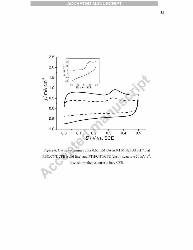
Cyclic voltammetry at a bare carbon film electrode showed that oxidation of uric acid occurs
at +0.58 V vs SCE (Figure 6, insert). When electrodes were modified with PBG/CNT and
PTH/CNT, the value of the oxidation peak potential was shifted negatively by more than
200 mV in each case, to +0.34 and +0.32 V, respectively, a good indication that the mediators
used are good electrocatalysts for uric acid oxidation.
The influence of the applied potential on the response of the UOx/PBG/CNT/CFE and
UOx/PTH/CNT/CFE biosensors was examined in the range -0.20 V to +0.40 V vs. SCE. In
all cases oxidation currents were observed, most probably due to mediator re-oxidation at the
electrode surface. The maximum current value obtained was at +0.20 V for
UOx/PTH/CNT/CFE and at +0.35 V for UOx/PBG/CNT/CFE. The difference is probably due
to the fact that the mediators used have slightly different redox couple potentials as seen in
Figures 2d2 and 2e2. In order to enable a comparison under the same conditions, a
compromise value of +0.30 V was chosen as the potential to apply in fixed potential
amperometry.
A comparison between the response to uric acid at CFE, PBG/CNT/CFE, PTH/CNT/CFE,
UOx/PBG/CNT/CFE and UOx/PTH/CNT/CFE was made under the same experimental
14��
conditions. The response at the bare electrode was around 130 and 170 times lower than
UOx/PTH/CNT/CFE and UOx/PBG/CNT/CFE, respectively, and the electrodes modified
with PTH/CNT/CFE and PBG/CNT/CFE exhibited 4 and 5 times lower sensitivity. Although
at the applied potential used, some direct oxidation of uric acid at bare electrode occurs, the
results clearly showed that the presence of enzyme greatly increases the response.
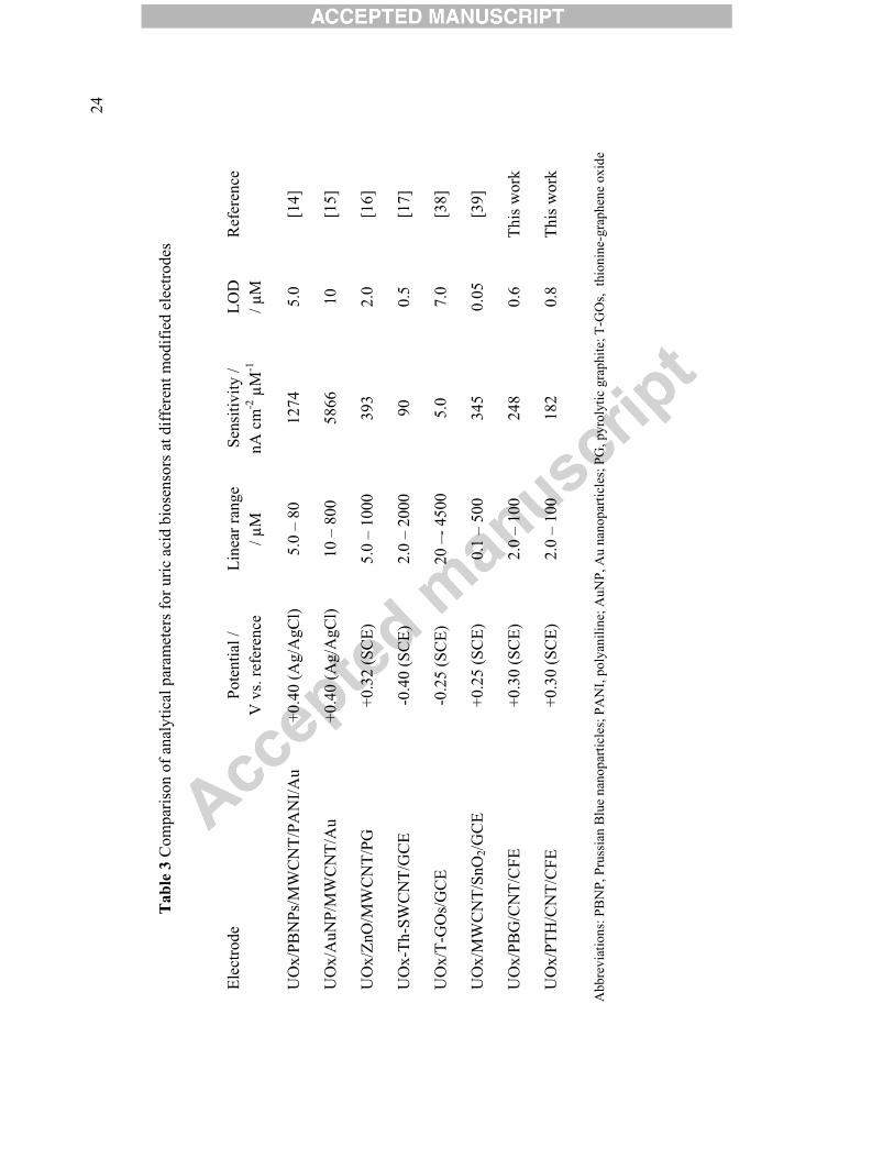
Calibration curves for the response to uric acid at UOx/PTH/CNT/CFE and
UOx/PBG/CNT/CFE are shown in Figure 5b and it is seen that the behaviour is similar, with
a linear range up to 100 μM and submicromolar detection limits. However, the electrode with
PBG exhibited a higher response. A comparison with other uricase based biosensors in similar
configurations as those here, the modifier layer containing CNT and polymers, was made, see
Table 3. The sensitivity obtained with the proposed biosensors is not as high as that reported
at gold electrodes modified with MWCNT operating at a higher potential of +0.4 V with
either Prussian blue, or gold nanoparticles [14, 15]; however, the detection limits of 5 μM
[14] and 10 μM [15] were much higher than here. A similar detection limit, 0.5 μM, was
achieved at GCE modified with thionine adsorbed on single wall CNT, UOx-Th-
SWCNT/GCE [17], but the sensitivity was much lower than that obtained with either of the
biosensors proposed here. Another uricase biosensor, containing thionine and graphene oxide
at glassy carbon electrode UOx/T-GOs/GCE [38] did not exhibit a higher response than here
(5.3 nA cm-2 μM-1) and the detection limit, 7 μM, was much higher.
Long term biosensor stability was assessed by constructing a calibration curve from 10
injections every three days, storing in phosphate buffer at 4 ºC when not in use. After 6
weeks, 70 % of the initial response was found with UOx/PBG/CNT/CFE and 60 % with the
UOx/PTH/CNT/CFE biosensor. The stability is better than that reported in [39], where the
response dropped to 79.5 % after 20 days of intermittent use, storing at 4ºC, or in [15] where
the electrode showed 75 % response after 45 days when used every 5 days, but less good than
15��
at UOx/PBNPs/MWCNT/PANI/Au, [14], which maintained 60 % of the initial activity after 7
months of weekly usage. However, and very interestingly, after seven months storage in
buffer at 4 ºC the response of both uricase biosensors developed here remained the same as
after 6 weeks.
Biosensor repeatability was tested by constructing three successive calibration curves and the
relative standard deviation was 2.7 % for UOx/PBG/CNT/CFE and 3.3 % for
UOx/PTH/CNT/CFE. The reproducibility between three different electrodes was assessed by
comparing the sensitivity under the same conditions and the RSD was 3.0 and 3.8 %,
respectively, for the two biosensors.
3.4 Interferences and determination in natural samples
Interference studies were conducted by placing the modified electrodes in buffer solution,
under continuous stirring. After waiting for the baseline current to stabilise, the analyte was
injected, followed by the interferents and, finally, the same amount of analyte was injected
again.
Measurements in samples were performed by standard addition, first adding the sample,
followed by 4 additions of analyte standard and determining the concentration of sample from
the linear regression parameters.
Glucose
Compounds usually present in matrices where glucose is determined such as ascorbic acid,
uric acid, dopamine and fructose were tested as potential interferents, using the same
concentration of glucose and interferents, 0.20 mM. No change in response was observed
from the tested compounds at either GOx/PBG/CNT/CFE or GOx/PTH/CNT/CFE biosensors,
thus showing a very high selectivity towards glucose.
16��
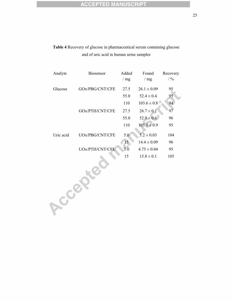
In order to check the precision and accuracy of the glucose biosensor, GOx/PBG/CNT/CFE
and GOx/PTH/CNT/CFE were applied to glucose determination in serum containing glucose
(labelled with 5.5 mg glucose per 100 mL). The sample acquired from the local pharmacy was
used as received and the determination of glucose was carried out by the standard addition
method: first, injection of the serum, followed by 4 additions of standard glucose of 0.1 or 0.2
mM. Three different concentrations were analysed in triplicate and the values are shown in
Table 4. Good recoveries ranging from 94 % to 97 % were obtained, which is encouraging for
application to natural samples.
Uric acid
For the interference study, different compounds usually found in human urine [40] were
tested, i.e. ammonia, ascorbic acid, creatinine, citric acid, glucose, phenol and urea. The
concentration of the interferents was 10 times higher than that of uric acid. Only ascorbic acid
responded, its presence inducing a 20 and 25 % increase in UOx/PBG/CNT/CFE and
UOx/PTH/CNT/CFE biosensor current response. However, in human urine the ascorbic acid
level is about 13 times lower than that of uric acid; hence, it should not be a problem for
determination by the standard addition method.
Urine samples from two healthy volunteers were analysed for uric acid and the values found
were 3.66 ± 0.040 and 4.17 ± 0.035 mM with UOx/PBG/CNT/CFE and 3.45 ± 0.035 and
4.05 ± 0.030 mM with the UOx/PTH/CNT/CFE biosensor, showing good agreement between
the two biosensors, the values being in the normal range [41]. Recovery measurements were
also performed by adding two different known concentrations to the urine samples and
determination in triplicate was performed with good precision; the values obtained did not
vary by more than 5 % from those expected, Table 4.
4. Conclusions
17��
Poly(thionine) and novel poly(brilliant green) have been formed onto multiwalled carbon
nanotube modified carbon film electrodes. The nanostructures were evaluated as platforms for
enzyme immobilisation with the aim of developing new biosensors. For glucose and uric acid
measurement, PBG-based enzyme biosensors exhibited a better response than PTH-based
enzyme biosensors, with a higher sensitivity and lower detection limit. The biosensors
developed here operated at less negative potentials for glucose and less positive for uric acid
determination than previously reported in the literature, and the analytical parameters
obtained with enzyme/PBG/CNT modified electrodes were better than others achieved by
other polymer/CNT based glucose and uric acid biosensors. Recovery measurements in
pharmaceutical and natural samples showed promising results, leading to the conclusion that
they can be successfully employed as electrochemical biosensors. Thus, these configurations
can be profitably used for developing other enzyme based biosensors and exploring
miniaturisation strategies.
Acknowledgements
Financial support from Fundação para a Ciência e a Tecnologia (FCT), Portugal, PTDC/QUI-
QUI/116091/2009, POCH, POFC-QREN (co-financed by FSE and European Community
FEDER funds through the program COMPETE – Programa Operacional Factores de
Competitividade under the projects PEst-C/EME/UI0285/2013) and CENTRO -07-0224 -
FEDER -002001 (MT4MOBI)) is gratefully acknowledged. M.E.G. thanks FCT for
postdoctoral fellowship SFRH/BPD/36930/2007.
18��
References
[1] V. Scognamiglio, Nanotechnology in glucose monitoring: advances and challenges in
the last 10 years, Biosens. Bioelectron. 47 (2013) 12-25.
[2] X. Yang, B. Feng, X. He, F. Li, Y. Ding, J. Fei, Carbon nanomaterial based
electrochemical sensors for biogenic amines, Microchim. Acta 180 (2013) 935-956.
[3] C.B. Jacobs, M.J. Peairs, B.J. Venton, Review: carbon nanotube based electrochemical
sensors for biomolecules, Anal. Chim. Acta 662 (2010) 105–127.
[4] S.K. Vashist, D. Zheng, K. Al-Rubeaan, J.H.T. Luong, F.S. Sheu, Advances in carbon
nanotube based electrochemical sensors for bioanalytical applications, Biotechnol. Adv.
29 (2011) 169–188.
[5] C.Y. Li, E.T. Thostenson, T.W. Chou, Sensors and actuators based on carbon nanotubes
and their composites: a review, Compos. Sci. Technol. 68 (2008) 1227–1249.
[6] R. Pauliukaite, M.E. Ghica, M.M. Barsan, C.M.A. Brett, Phenazines and
polyphenazines in electrochemical sensors and biosensors, Anal. Lett. 43 (2010) 1588-
1608.
[7] A.C. Torres, M.E. Ghica, C.M.A. Brett, Poly(neutral red)/cholesterol oxidase modified
carbon film electrode for cholesterol biosensing, Electroanalysis 24 ( 2012) 1547-1553.
[8] S. Kakhky, M.M. Barsan, E. Shams, C.M.A. Brett, New robust redox and conducting
polymer modified electrodes for ascorbate sensing and glucose biosensing,
Electroanalysis 25 (2013) 77-84.
[9] H.Y. Huo, H.Q. Luo, N.B. Li, Electrochemical sensor for heparin based on a
poly(thionine) modified glassy carbon electrode, Microchim. Acta 167 (2009)195-199.
[10] M. Mazloum-Ardakani, M.A. Sheikh-Mohseni, Carbon nanotubes in electrochemical
sensors, in: Dr. Mohammad Naraghi (ed.), Carbon nanotubes - growth and applications,
InTech, 2011, Ch. 15.�
[11] Q. Gao, M. Sun, P. Peng, H. Qi, C. Zhang, Electro-oxidative polymerization of
phenothiazine dyes into a multilayer-containing carbon nanotube on a glassy carbon for
the sensitive and low-potential detection of NADH, Microchim. Acta 168 (2010)
299-307.
[12] D.I. Feig, D.-H. Fang, R.J. Johnson, Uric acid and cardiovascular risk, New Engl. J.
Med. 359 (2008) 1811-1821.
19��
[13] M.E. Ghica, R. Pauliukaite, O. Fatibello-Filho, C.M.A. Brett, Application of
functionalised carbon nanotubes immobilised into chitosan films in amperometric
enzyme biosensors, Sens. Actuator B-Chem. 142 (2009) 308-315.
[14] R. Rawal, S. Chawla, N. Chauhan, T. Dahyia, C.S. Pundir, Construction of
amperometric uric acid biosensor based on uricase immobilized on
PBNPs/cMWCNT/PANI/Au composite, Int. J. Biol. Macromol. 50 (2012) 112-118.
[15] C. Chauhan, C.S. Pundir, An amperometric uric acid biosensor based on multiwalled
carbon nanotube-gold nanoparticle composite, Anal. Biochem. 413 (2011) 97-103.
[16] Y. Wang, L. Yu, Z. Zhu, J. Zhang, J. Zhu, Novel uric acid sensor based on enzyme
electrode modified by ZnO nanoparticles and multiwalled carbon nanotubes, Anal.
Lett. 42 (2009) 775-789.
[17] D. Chen, Q. Wang, J. Jin, P. Wu, H. Wang, S. Yu, H. Zhang, C. Cai, Low-potential
detection of endogenous and physiological uric acid at uricase-thionine-single-walled
carbon nanotube modified electrodes, Anal. Chem. 82 (2010) 2448-2455.
[18] R. Yu, L. Wang, Q. Xie, S. Yao, High-performance amperometric sensor using catalytic
platinum nanoparticles-thionine-multiwalled carbon nanotubes nanocomposite,
Electroanalysis 22 (2010) 2856-2861.
[19] C.M.A. Brett, L. Angnes, H.-D. Liess, Carbon film resistors as electrodes: voltammetric
properties and application in electroanalysis, Electroanalysis 13 (2001) 765-769.
[20] C. Gouveia-Caridade, R. Pauliukaite, C.M.A. Brett, Development of electrochemical
oxidase biosensors based on carbon nanotube-modified carbon film electrodes for
glucose and ethanol, Electrochim. Acta 53 (2008) 6732-6739.
[21] M.N. Tchoul, W.T. Ford, G. Lolli, D.E. Resasco, S. Arepalli, Effect of mild nitric acid
oxidation on dispersability, size and structure of single-walled carbon nanotubes, Chem.
Mater. 19 (2007) 5765–5772.
[22] X. Wang, N. Yang, Q. Wan, X. Wang, Catalytic capability of poly(malachite green)
films based electrochemical sensor for oxidation of dopamine, Sens. Actuator B-Chem.
128 (2007) 83-90.
[23] M.E. Ghica, Y. Wintersteller, C.M.A. Brett, Poly(brilliant green)/carbon nanotube
modified carbon film electrodes and application as sensors, J. Solid State Electrochem.
17 (2013) 1571-1580.
[24] E. Topçu, M. Alanyal�oglu, Electrochemical formation of poly(thionine) thin films: the
effect of amine group on the polymeric film formation of phenothiazine dyes, J. Appl.
Polym. Sci. 2014, DOI: 10.1002/APP.39686
20��
[25] A.A Karyakin, E.E Karyakina, H.-L. Schmid, Electropolymerized azines: A new group
of electroactive polymers, Electroanalysis 11 (1999) 149-155.
[26] M.M. Barsan, E.M. Pinto, C.M.A. Brett, Electrosynthesis and electrochemical
characterisation of phenazine polymers for application in biosensors, Electrochim. Acta
53 (2008) 3973–3982.
[27] R. Carvalho, C. Gouveia Caridade, C.M.A. Brett, Glassy carbon electrodes modified by
multiwalled carbon nanotubes and poly(neutral red): a comparative study of different
brands and application to electrocatalytic ascorbate determination, Anal. Bioanal.
Chem. 398 (2010) 1675-1685.
[28] M.E. Ghica, C.M.A. Brett, The influence of carbon nanotubes and polyazine redox
mediators on the performance of amperometric enzyme biosensors, Microchim. Acta
170 (2010) 257-265.
[29] J.A. Rather, S. Pilehvar, K. De Wael, A biosensor fabricated by incorporation of redox
mediator into a carbon nanotube/Nafion composite for tyrosinase immobilization:
detection of matairesinol, an endocrine disruptor, Analyst 138 (2013) 204-210.
[30] C. Deng, J. Chen, Z. Nie, M. Yang, S. Si, Electrochemical detection of nitrite based on
the polythionine/carbon nanotube modified electrode, Thin Solid Films 520 (2012)
7026-7029.
[31] R. Pauliukaite, M.E. Ghica, M.M. Barsan, C.M.A. Brett, Characterisation of
poly(neutral red) modified carbon film electrodes; application as a redox mediator for
biosensors. J. Solid State Electrochem. 11(2007) 899-908.
[32] X. Xiao, B. Zhou, L. Zhu, L. Xu, L. Tan, H. Tang, Y. Zhang, Q. Xie, S. Yao, An
reagentless glucose biosensor based on direct electrochemistry of glucose oxidase
immobilised on poly(methylene blue) doped silica nanocomposites. Sens. Actuat. B 165
(2012) 126-132.
[33] M.M. Barsan, R.C. Carvalho, Y. Zhong, X. Sun, C.M.A. Brett, Carbon nanotube
modified carbon cloth electrodes: characterisation and application as biosensors,
Electrochim. Acta 85 (2012) 203-209.
[34] B. Unnikrishnan, S. Palanisamy, S.-M. Chen, A simple electrochemical approach to
fabricate a glucose biosensor based on graphene-glucose oxidase biocomposite,
Biosens. Bioelectron. 39 (2013) 70-75.
[35] F. Hu, S. Chen, C. Wang, R. Yuan, Y. Chai, Y. Xiang, C. Wang, ZnO nanoparticle and
multiwalled carbon nanotubes for glucose oxidase direct electron transfer and
electrocatalytic activity investigation, J. Mol. Catal. B-Enzym. 72 (2011) 298-304.
21��
[36] Y.-L. Yao, K.-K. Shiu, Low potential detection of glucose at carbon nanotube modified
glassy carbon electrode with electropolymerized poly(toluidine blue O) film,
Electrochim. Acta 53 (2007) 278-284.
[37] Y. Fang, Y. Ni, G. Zhang, C. Mao, X. Huang, J. Shen, Biocompatibility of CS-PPy
nanocomposites and their application to glucose biosensor, Bioelectrochemistry 88
(2012) 1-7.
[38] Z. Sun, H. Fu, L. Deng, J. Wang, Redox-active thionine-graphene oxide hybrid
nanosheet: one-pot, rapid synthesis, and application as a sensing platform for uric acid,
Anal. Chim. Acta 761 (2013) 84-91.
[39] F.-F. Zhang, X.-L. Wang, C.-X. Li, X.-H. Li, Q. Wan, Y.Z. Xian, L.-T. Jin, K.
Yamamoto, Assay for uric acid level in rat striatum by a reagentless biosensor based on
functionalized multi-wall carbon nanotubes with tin oxide, Anal. Bioanal. Chem. 382
(2005) 1368-1373.
[40] D.F. Putnam, Composition and concentrative properties of human urine, NASA
Contractor Report, Washington D.C. July 1971.
[41] C. Zhao, L. Wan, Q. Wang, S. Liu, K. Jiao, Highly sensitive and selective uric acid
biosensor based on direct electron transfer of hemoglobin-encapsulated chitosan –
modified glassy carbon electrode, Anal. Sci. 25 (2009) 1013-1017.
22�
� Tab
les
Tab
le 1
Dat
a ob
tain
ed fr
om e
quiv
alen
t circ
uit f
ittin
g of
the
impe
danc
e sp
ectra
for t
he b
are
and
mod
ified
ele
ctro
des i
n 0.
1 M
NaP
BS
at p
H 7
.0.
Elec
trode
R c
t /
� c
m2
CPE
dl /
μF c
m-2
s�-1
� 1
R f /
k� c
m2
CPE
f /
mF
cm-2
s�-1
� 2
CFE
-
17.0
0.
90
- -
-
PBG
/CFE
22
0 32
.8
0.82
2.
7 0.
03
0.92
PTH
/CFE
7.
4 28
.3
0.73
47
0.
19
0.76
CN
T/C
FE
6.2
99.6
0.
71
- 7.
3 0.
92
PBG
/CN
T/C
FE
4.4
97.0
0.
69
- 14
.0
0.88
PTH
/CN
T/C
FE
5.9
30.6
0.
73
- 10
.5
0.91
23�
�
Tab
le 2
Com
paris
on o
f ana
lytic
al p
aram
eter
s for
glu
cose
bio
sens
ors a
t diff
eren
t mod
ified
ele
ctro
des
Elec
trode
Po
tent
ial /
V
vs.
refe
renc
e Li
near
rang
e / m
M
Sens
itivi
ty /
μA m
M-1
cm
-2
LOD
/ μ
M
Ref
eren
ce
GO
x/Pt
NPs
-TH
-MW
CN
T/A
u +0
.50
V (S
CE)
0.
001
– 11
.1
140
0.05
[1
8]
GO
x/PN
R/C
NT/
GC
E -0
.30
V (S
CE)
0.
2 –
1.6
30.4
17
[2
8]
GO
x/PB
CB
/CN
T/G
CE
-0.3
0 V
(SC
E)
0.2
– 1.
6 10
.1
14
[28]
GO
x/PE
DO
T/C
NT-
CC
l -0
.30
V (S
CE)
0.
2 –
1.2
33.4
0.
065
[33]
GO
x/R
GO
/GC
E -0
.447
(Ag/
AgC
l) 0.
1 –
27
1.85
*
[34]
GO
x/Zn
O/G
Ox/
MW
CN
T/G
CE
-0.3
0 V
(SC
E)
0.00
67 –
1.2
9 10
.0
2.22
[3
5]
GO
x-PT
BO
/CN
T/G
CE
-0.1
0 V
(Ag/
AgC
l) 1.
0 –
7.0
14.5
*
[36]
GO
x/C
S-PP
y/G
CE
+0.1
32 (S
CE)
0.
5 –
147
3.34
15
.5
[37]
GO
x/PB
G/C
NT/
CFE
-0
.20
V (S
CE)
0.
2 –
1.2
32.4
12
Th
is w
ork
GO
x/PT
H/C
NT/
CFE
-0
.20
V (S
CE)
0.
2 –
1.2
24.6
30
Th
is w
ork
*-n
ot sp
ecifi
ed
A
bbre
viat
ions
: PtN
Ps, P
t nan
opar
ticle
s; P
NR
, pol
y(ne
utra
l red
); PB
CB
, pol
y(br
illia
nt c
resy
l blu
e); P
EDO
T, p
oly(
3,4-
ethy
lene
diox
ythi
ophe
ne);
CC
l, ca
rbon
clo
th; R
GO
, red
uced
gra
phen
e ox
ide;
PTB
O, p
oly(
tolu
idin
e bl
ue O
); C
S-PP
y, c
hito
san-
poly
pyrr
ole,
24�
�
Tab
le 3
Com
paris
on o
f ana
lytic
al p
aram
eter
s for
uric
aci
d bi
osen
sors
at d
iffer
ent m
odifi
ed e
lect
rode
s
Elec
trode
Po
tent
ial /
V
vs.
refe
renc
e Li
near
rang
e / μ
M
Sens
itivi
ty /
nA c
m-2
μM
-1
LOD
/ μ
M
Ref
eren
ce
UO
x/PB
NPs
/MW
CN
T/PA
NI/A
u +0
.40
(Ag/
AgC
l) 5.
0 –
80
1274
5.
0 [1
4]
UO
x/A
uNP/
MW
CN
T/A
u +0
.40
(Ag/
AgC
l) 10
– 8
00
5866
10
[1
5]
UO
x/Zn
O/M
WC
NT/
PG
+0.3
2 (S
CE)
5.
0 –
1000
39
3 2.
0 [1
6]
UO
x-Th
-SW
CN
T/G
CE
-0.4
0 (S
CE)
2.
0 –
2000
90
0.
5 [1
7]
UO
x/T-
GO
s/G
CE
-0.2
5 (S
CE)
20
–- 4
500
5.0
7.0
[38]
UO
x/M
WC
NT/
SnO
2/GC
E +0
.25
(SC
E)
0.1
– 50
0 34
5 0.
05
[39]
UO
x/PB
G/C
NT/
CFE
+0
.30
(SC
E)
2.0
– 10
0 24
8 0.
6 Th
is w
ork
UO
x/PT
H/C
NT/
CFE
+0
.30
(SC
E)
2.0
– 10
0 18
2 0.
8 Th
is w
ork
A
bbre
viat
ions
: PB
NP,
Pru
ssia
n B
lue
nano
parti
cles
; PA
NI,
poly
anili
ne; A
uNP,
Au
nano
parti
cles
; PG
, pyr
olyt
ic g
raph
ite; T
-GO
s, th
ioni
ne-g
raph
ene
oxid
e
25��
Table 4 Recovery of glucose in pharmaceutical serum containing glucose
and of uric acid in human urine samples
Analyte Biosensor Added / mg
Found / mg
Recovery / %
Glucose
GOx/PBG/CNT/CFE 27.5
55.0
110
26.1 ± 0.09
52.4 ± 0.4
103.6 ± 0.8
95
95
94
GOx/PTH/CNT/CFE 27.5
55.0
110
26.7 ± 0.1
52.9 ± 0.6
105.0 ± 0.9
97
96
95
Uric acid UOx/PBG/CNT/CFE 5.0
15
5.2 ± 0.03
14.4 ± 0.09
104
96
UOx/PTH/CNT/CFE 5.0
15
4.75 ± 0.04
15.8 ± 0.1
95
105
26��
Figure captions
Scheme 1. Chemical structure of monomers (a) brilliant green and (b) thionine.
Figure 1. Cyclic voltammetry for polymerisation at CNT/CFE of (a) 1.0 mM BG at
100 mV s-1 in McIlvaine buffer pH 4.0 and (b) 1.0 mM TH at 50 mV s-1 in 0.025 M Na2B4O7
+0.10 M KNO3, pH 9.0. Insets show polymerization under the same conditions at CFE.
Figure 2. Scanning electron micrographs of (a1) CFE, (b1) PTH/CFE, (c1) PBG/CFE,
(d1) PTH/CNT/CFE and (e1) PBG/CNT/CFE and (a2) to (d2) their respective cyclic
voltammograms in 0.1 M NaPBS pH 7.0.
Figure 3. Complex plane impedance spectra for different electrodes (a) CFE (�),
PBG/CFE (�), PTH/CFE (�) and (b) CNT/CFE (�), PBG/CNT/CFE (�),
PTH/CNT/CFE (�) at 0.0 V vs. SCE in 0.1 M NaPBS, pH 7.0. Insets are magnifications of
high frequency portion. Lines show equivalent circuit fitting (see Fig.4 for electrical circuits).
Figure 4. Equivalent circuits used for fitting the spectra of (a) CFE; (b) PBG/CFE and
PTH/CFE and (c) CNT/CFE, PBG/CNT/CFE and PTH/CNT/CFE.
Figure 5. Calibration curves for (a) glucose at (�) GOx/PBG/CNT/CFE and
(�) GOx/PTH/CNT/CFE biosensors at -0.20 V and (b) for UA at (�) UOx/PBG/CNT/CFE
and (�) UOx/PTH/CNT/CFE biosensors at + 0.30 V vs. SCE in 0.1 M NaPBS, pH 7.0. Inset
shows (a) typical response at glucose biosensor and (b) linear range for uric acid.
Figure 6. Cyclic voltammetry for 0.60 mM UA in 0.1 M NaPBS pH 7.0 at PBG/ CNT/CFE
(solid line) and PTH/CNT/CFE (dash); scan rate 50 mV s-1. Inset shows the response at bare
CFE.
27��
N+
N
(a)
(b)
Scheme 1. Chemical structure of monomers (a) brilliant green and (b) thionine.
S+
N
NH2 NH2
28��
(a)
(b)
Figure 1. Cyclic voltammetry for polymerisation at CNT/CFE of (a) 1.0 mM BG at
100 mV s-1 in McIlvaine buffer pH 4.0 and (b) 1.0 mM TH at 50 mV s-1 in 0.025 M Na2B4O7
+0.10 M KNO3, pH 9.0. Insets show polymerisation under the same conditions at CFE.
-0.5 0.0 0.5 1.0
-1
0
1
2
3
TH1c
TH1a
PTH1c
j/ m
A c
m-2
E / V vs. SCE
PTH1a
-1.0 -0.5 0.0 0.5 1.0-90
-60
-30
0
30
60
90
TH1c
TH1a
PTH1c
j / �
A c
m-2
E / V vs. SCE
PTH1a
-1.0 -0.5 0.0 0.5 1.0-4
-2
0
2
4
6
8
10
BG3c
BG1
BG2a
PBG1c
j / m
A c
m-2
E / V vs. SCE
PBG1a-1.0 -0.5 0.0 0.5 1.0
-14
-7
0
7
14
21
28 BG1
BG3c"BG3c´
BG2c
BG2a
PBG1c
j / �
A cm
-2E / V vs. SCE
PBG1a
29��
Figure 2. Scanning electron micrographs of (a1) CFE, (b1) PBG/CFE, (c1) PTH/CFE
(d1) PBG/CNT/CFE and (e1) PTH/CNT/CFE and (a2) to (e2) their respective
cyclic voltammograms in 0.1 M NaPBS pH 7.0.
(a1)
-0.6 -0.4 -0.2 0.0 0.2 0.4 0.6-120
-90
-60
-30
0
30
60
j / �
A cm
-2
E / V vs. SCE
(c2)
-0.4 -0.2 0.0 0.2 0.4 0.6 0.8
-6
-4
-2
0
2
j / �
A cm
-2
E / V vs. SCE
(b2)
-0.8 -0.6 -0.4 -0.2 0.0 0.2 0.4 0.6 0.8-2.0
-1.5
-1.0
-0.5
0.0
0.5
1.0
1.5
j / m
A c
m-2
E / V vs. SCE
(e2)
-0.6 -0.4 -0.2 0.0 0.2 0.4 0.6
-1.5
-1.0
-0.5
0.0
0.5
1.0
1.5
2.0
j / m
A c
m-2
E / V vs. SCE
(d2)
0.0 0.2 0.4 0.6 0.8 1.0-20
0
20
40
60
80
100
j / �
A c
m-2
E / V vs. SCE
(a2)
100 μm
(a1)
100 μm
(b1)
(c1)
100 μm
(d1)
100 μm
(e1)
100 μm
30��
(a)
(b)
Figure 3. Complex plane impedance spectra for different electrodes (a) CFE (�),
PBG/CFE (�), PTH/CFE (�) and (b) CNT/CFE (�), PBG/CNT/CFE (�),
PTH/CNT/CFE (�) at 0.0 V vs. SCE in 0.1 M NaPBS, pH 7.0. Insets are the magnifications
of the high frequency portion. Lines show equivalent circuit fitting (see Fig.4 for electrical
circuits).
0.00 0.01 0.020.00
0.01
0.02
- Z "
/ k�
cm
2
Z ´/ k� cm2
0.00 0.05 0.10 0.15 0.200.00
0.05
0.10
0.15
0.20
CNT/CFE PBG/CNT/CFE PTH/CNT/CFE
- Z "
/ k�
cm
2
Z ´/ k� cm2
0.16 Hz
0 15 30 450
15
30
45
CFE PBG/CFE PTH/CFE
-Z "
/ k�
cm
2
Z ´/ k� cm2
0.13 Hz
0.00 0.02 0.040.00
0.02
0.04
- Z "
/ k�
cm
2
Z ´/ k� cm2
31��
(a)
(b)
(c)
Figure 4. Equivalent circuits used for fitting the spectra of (a) CFE; (b) PBG/CFE and
PTH/CFE and (c) CNT/CFE, PBG/CNT/CFE and PTH/CNT/CFE.
R��
CPEdl
Rct
CPEf
Rf
R��
CPEdl
Rct
CPEf
R�R�
CPEdl
32��
(a)
(b)
Figure 5. Calibration curves for (a) glucose at (�) GOx/PBG/CNT/CFE and
(�) GOx/PTH/CNT/CFE biosensors at -0.20 V and (b) for UA at (�) UOx/PBG/CNT/CFE
and (�) UOx/PTH/CNT/CFE biosensors at + 0.30 V vs. SCE in 0.1 M NaPBS, pH 7.0.
Inset shows (a) typical response at glucose biosensor and (b) linear range for uric acid.
0.0 0.5 1.0 1.5 2.0 2.5 3.00
5
10
15
20
25
30
35
40 GOx/PBG/CNT/CFE GOx/PTH/CNT/CFE
�j /
�A
cm
-2
[Glucose] / mM
0.0 0.1 0.2 0.3 0.4 0.5 0.60
9
18
27
36
45 UOx/PBG/CNT/CFE UOx/PTH/CNT/CFE
�j /
�A
cm
-2
[UA] / mM
0.00 0.02 0.04 0.06 0.08 0.100
5
10
15
20
25
�j / �A
cm
-2
[UA] / mM
400 800 1200 1600
-10
-8
-6
-4
I / �
A
t / s
33��
Figure 6. Cyclic voltammetry for 0.60 mM UA in 0.1 M NaPBS pH 7.0 at
PBG/CNT/CFE (solid line) and PTH/CNT/CFE (dash); scan rate 50 mV s-1.
Inset shows the response at bare CFE.
0.0 0.1 0.2 0.3 0.4 0.5-1.0
-0.5
0.0
0.5
1.0
1.5
2.0
2.5
j / m
A c
m-2
E / V vs. SCE
0.0 0.2 0.4 0.6 0.8
-10
-5
0
5
10
15
20
j / �
A cm
-2
E / V vs. SCE
34��
Graphical�Abstract�
�
Poly(brilliant�green)�and�poly(thionine)�modified�carbon�nanotube�coated��
carbon�film�electrodes�for�glucose�and�uric�acid�biosensors�
�
�
�
�
�
�
�
�
�
�
�
�
CFE CNT
PBG/CNT/CFE
CFE
CFE
PTH/CNT/CFE
CFE
PTH
PB
S+
N
NH2 NH2
N+
N
Related Documents