PolyWorks ® Modeling and Inspection Software Suite

Poly Works Reference Guide
Jan 29, 2016
polyworks
Welcome message from author
This document is posted to help you gain knowledge. Please leave a comment to let me know what you think about it! Share it to your friends and learn new things together.
Transcript

PolyWorks®Modeling and Inspection Software Suite

© 1995–2015 InnovMetric Software Inc. All rights reserved.
This manual, as well as the software described in it, is furnished under license and may be used or copied only in accordance with the terms of such license. The content of this document is furnished for informational use only, and is subject to change without notice. InnovMetric Software Inc. assumes no responsibility or liability for any errors or inaccuracies that may appear in this document.
Except as permitted by such license, reproduction in whole or in part in any way without written permission from InnovMetric Software is strictly prohibited.
PolyWorks® is a registered trademark of InnovMetric Software Inc. InnovMetric, PolyWorks|Inspector, PolyWorks|Inspector Probing, PolyWorks|Modeler, PolyWorks|Talisman, PolyWorks|Viewer, PolyWorks|Surveyor, IMInspect, IMInspect Probing, IMInspect Scanning & Probing, IMEdit, IMAlign, IMMerge, IMCompress, IMTexture, IMSurvey, and "The Universal 3D Metrology Software Platform" are trademarks of InnovMetric Software Inc. SmartGD&T is a trademark of Multi Metrics Inc. All other trademarks are the property of their respective owners.
Acknowledgments
© 1995, © 1998-2000 National Research Council of Canada
© 1997-1999 Hymarc Ltd. (hs2pol translator)
This work contains software owned by Siemens Product Lifecycle Management Software Inc. © 1986-2013
Portions of this software are owned by Spatial Corp. © 1986-2015 Spatial Corp. All rights reserved.
Portions of this software are copyright © 1996-2004 The FreeType Project (www.freetype.org). All rights reserved.
This software is based in part on the work of the Independent JPEG Group.
This product includes software developed by the OpenSSL Project for use in the OpenSSL Toolkit (http://www.openssl.org/).
Copyright © 1998-2011 The OpenSSL Project. All rights reserved.
Redistribution and use in source and binary forms, with or without modification, are permitted provided that the following conditions are met:
1. Redistributions of source code must retain the above copyright notice, this list of conditions and the following disclaimer.

2. Redistributions in binary form must reproduce the above copyright notice, this list of conditions and the following disclaimer in the documentation and/or other materials provided with the distribution.
3. All advertising materials mentioning features or use of this software must display the following acknowledgment:
“This product includes software developed by the OpenSSL Project for use in the OpenSSL Toolkit. (http://www.openssl.org/)"
4. The names "OpenSSL Toolkit" and "OpenSSL Project" must not be used to endorse or promote products derived from this software without prior written permission. For written permission, please contact [email protected].
5. Products derived from this software may not be called "OpenSSL" nor may "OpenSSL" appear in their names without prior written permission of the OpenSSL Project.
6. Redistributions of any form whatsoever must retain the following acknowledgment:
"This product includes software developed by the OpenSSL Project for use in the OpenSSL Toolkit (http://www.openssl.org/)"
THIS SOFTWARE IS PROVIDED BY THE OpenSSL PROJECT ''AS IS'' AND ANY EXPRESSED OR IMPLIED WARRANTIES, INCLUDING, BUT NOT LIMITED TO, THE IMPLIED WARRANTIES OF MERCHANTABILITY AND FITNESS FOR A PARTICULAR PURPOSE ARE DISCLAIMED. IN NO EVENT SHALL THE OpenSSL PROJECT OR ITS CONTRIBUTORS BE LIABLE FOR ANY DIRECT, INDIRECT, INCIDENTAL, SPECIAL, EXEMPLARY, OR CONSEQUENTIAL DAMAGES (INCLUDING, BUT NOT LIMITED TO, PROCUREMENT OF SUBSTITUTE GOODS OR SERVICES; LOSS OF USE, DATA, OR PROFITS; OR BUSINESS INTERRUPTION) HOWEVER CAUSED AND ON ANY THEORY OF LIABILITY, WHETHER IN CONTRACT, STRICT LIABILITY, OR TORT (INCLUDING NEGLIGENCE OR OTHERWISE) ARISING IN ANY WAY OUT OF THE USE OF THIS SOFTWARE, EVEN IF ADVISED OF THE POSSIBILITY OF SUCH DAMAGE.
This product includes software written by Tim Hudson ([email protected]).
This product includes cryptographic software written by Eric Young ([email protected]). All rights reserved.
Copyright © 1995-1998 Eric Young ([email protected])All rights reserved.
This package is an SSL implementation written by Eric Young ([email protected]). The implementation was written so as to conform with Netscapes SSL.
This library is free for commercial and non-commercial use as long as the following conditions are adhered to. The following conditions apply to all code found in this distribution, be it the RC4, RSA, lhash, DES, etc., code; not just the SSL code. The SSL documentation included with this distribution is covered by the same copyright terms except that the holder is Tim Hudson ([email protected]).
Copyright remains Eric Young's, and as such any Copyright notices in the code are not to be removed. If this package is used in a product, Eric Young should be given attribution as the

author of the parts of the library used. This can be in the form of a textual message at program startup or in documentation (online or textual) provided with the package.
Redistribution and use in source and binary forms, with or without modification, are permitted provided that the following conditions are met:
1. Redistributions of source code must retain the copyright notice, this list of conditions and the following disclaimer.
2. Redistributions in binary form must reproduce the above copyright notice, this list of conditions and the following disclaimer in the documentation and/or other materials provided with the distribution.
3. All advertising materials mentioning features or use of this software must display the following acknowledgment:
"This product includes cryptographic software written by Eric Young ([email protected])"
The word 'cryptographic' can be left out if the routines from the library being used are not cryptographic related :-).
4. If you include any Windows specific code (or a derivative thereof ) from the apps folder (application code) you must include an acknowledgment:
"This product includes software written by Tim Hudson ([email protected])"
THIS SOFTWARE IS PROVIDED BY ERIC YOUNG ``AS IS'' AND ANY EXPRESS OR IMPLIED WARRANTIES, INCLUDING, BUT NOT LIMITED TO, THE IMPLIED WARRANTIES OF MERCHANTABILITY AND FITNESS FOR A PARTICULAR PURPOSE ARE DISCLAIMED. IN NO EVENT SHALL THE AUTHOR OR CONTRIBUTORS BE LIABLE FOR ANY DIRECT, INDIRECT, INCIDENTAL, SPECIAL, EXEMPLARY, OR CONSEQUENTIAL DAMAGES (INCLUDING, BUT NOT LIMITED TO, PROCUREMENT OF SUBSTITUTE GOODS OR SERVICES; LOSS OF USE, DATA, OR PROFITS; OR BUSINESS INTERRUPTION) HOWEVER CAUSED AND ON ANY THEORY OF LIABILITY, WHETHER IN CONTRACT, STRICT LIABILITY, OR TORT (INCLUDING NEGLIGENCE OR OTHERWISE) ARISING IN ANY WAY OUT OF THE USE OF THIS SOFTWARE, EVEN IF ADVISED OF THE POSSIBILITY OF SUCH DAMAGE.
The licence and distribution terms for any publicly available version or derivative of this code cannot be changed. i.e. this code cannot simply be copied and put under another distribution license [including the GNU Public Licence.]
Copyright © 1998-2002 by Neil Hodgson [email protected]
NEIL HODGSON DISCLAIMS ALL WARRANTIES WITH REGARD TO THIS SOFTWARE, INCLUDING ALL IMPLIED WARRANTIES OF MERCHANTABILITY AND FITNESS, IN NO EVENT SHALL NEIL HODGSON BE LIABLE FOR ANY SPECIAL, INDIRECT OR CONSEQUENTIAL DAMAGES OR ANY DAMAGES WHATSOEVER RESULTING FROM LOSS OF USE, DATA OR PROFITS, WHETHER IN AN ACTION OF CONTRACT, NEGLIGENCE OR OTHER TORTIOUS ACTION, ARISING OUT OF OR IN CONNECTION WITH THE USE OR PERFORMANCE OF THIS SOFTWARE.
Copyright © 1988-1997 Sam Leffler

Copyright © 1991-1997 Silicon Graphics, Inc.
THE SOFTWARE IS PROVIDED "AS-IS" AND WITHOUT WARRANTY OF ANY KIND, EXPRESS, IMPLIED OR OTHERWISE, INCLUDING WITHOUT LIMITATION, ANY WARRANTY OF MERCHANTABILITY OR FITNESS FOR A PARTICULAR PURPOSE.
IN NO EVENT SHALL SAM LEFFLER OR SILICON GRAPHICS BE LIABLE FOR ANY SPECIAL, INCIDENTAL, INDIRECT OR CONSEQUENTIAL DAMAGES OF ANY KIND, OR ANY DAMAGES WHATSOEVER RESULTING FROM LOSS OF USE, DATA OR PROFITS, WHETHER OR NOT ADVISED OF THE POSSIBILITY OF DAMAGE, AND ON ANY THEORY OF LIABILITY, ARISING OUT OF OR IN CONNECTION WITH THE USE OR PERFORMANCE OF THIS SOFTWARE.
Copyright © 2001-3 Henry Maddocks
THE SOFTWARE IS PROVIDED "AS IS", WITHOUT WARRANTY OF ANY KIND, EXPRESS OR IMPLIED, INCLUDING BUT NOT LIMITED TO THE WARRANTIES OF MERCHANTABILITY, FITNESS FOR A PARTICULAR PURPOSE AND NONINFRINGEMENT. IN NO EVENT SHALL THE AUTHORS OR COPYRIGHT HOLDERS BE LIABLE FOR ANY CLAIM, DAMAGES OR OTHER LIABILITY, WHETHER IN AN ACTION OF CONTRACT, TORT OR OTHERWISE, ARISING FROM, OUT OF OR IN CONNECTION WITH THE SOFTWARE OR THE USE OR OTHER DEALINGS IN THE SOFTWARE.
Copyright © 2015 THL A29 Limited, a Tencent company, and Milo Yip. All rights reserved.
THE SOFTWARE IS PROVIDED "AS IS", WITHOUT WARRANTY OF ANY KIND, EXPRESS OR IMPLIED, INCLUDING BUT NOT LIMITED TO THE WARRANTIES OF MERCHANTABILITY, FITNESS FOR A PARTICULAR PURPOSE AND NONINFRINGEMENT. IN NO EVENT SHALL THE AUTHORS OR COPYRIGHT HOLDERS BE LIABLE FOR ANY CLAIM, DAMAGES OR OTHER LIABILITY, WHETHER IN AN ACTION OF CONTRACT, TORT OR OTHERWISE, ARISING FROM, OUT OF OR IN CONNECTION WITH THE SOFTWARE OR THE USE OR OTHER DEALINGS IN THE SOFTWARE.
Copyright © 2006-2013 Alexander Chemeris. All rights reserved.
Redistribution and use in source and binary forms, with or without modification, are permitted provided that the following conditions are met:
Redistributions of source code must retain the above copyright notice, this list of conditions and the following disclaimer.
Redistributions in binary form must reproduce the above copyright notice, this list of conditions and the following disclaimer in the documentation and/or other materials provided with the distribution.
Neither the name of copyright holder nor the names of its contributors may be used to endorse or promote products derived from this software without specific prior written permission.
THIS SOFTWARE IS PROVIDED BY THE REGENTS AND CONTRIBUTORS ``AS IS'' AND ANY EXPRESS OR IMPLIED WARRANTIES, INCLUDING, BUT NOT LIMITED TO, THE IMPLIED WARRANTIES OF MERCHANTABILITY AND FITNESS FOR A PARTICULAR PURPOSE ARE DISCLAIMED. IN NO EVENT SHALL THE REGENTS AND CONTRIBUTORS BE LIABLE FOR ANY DIRECT, INDIRECT, INCIDENTAL, SPECIAL, EXEMPLARY, OR CONSEQUENTIAL DAMAGES (INCLUDING, BUT NOT LIMITED TO, PROCUREMENT OF SUBSTITUTE GOODS OR SERVICES;

LOSS OF USE, DATA, OR PROFITS; OR BUSINESS INTERRUPTION) HOWEVER CAUSED AND ON ANY THEORY OF LIABILITY, WHETHER IN CONTRACT, STRICT LIABILITY, OR TORT (INCLUDING NEGLIGENCE OR OTHERWISE) ARISING IN ANY WAY OUT OF THE USE OF THIS SOFTWARE, EVEN IF ADVISED OF THE POSSIBILITY OF SUCH DAMAGE.
Copyright © 2002 JSON.org. All Rights Reserved.
THE SOFTWARE IS PROVIDED "AS IS", WITHOUT WARRANTY OF ANY KIND, EXPRESS OR IMPLIED, INCLUDING BUT NOT LIMITED TO THE WARRANTIES OF MERCHANTABILITY, FITNESS FOR A PARTICULAR PURPOSE AND NONINFRINGEMENT. IN NO EVENT SHALL THE AUTHORS OR COPYRIGHT HOLDERS BE LIABLE FOR ANY CLAIM, DAMAGES OR OTHER LIABILITY, WHETHER IN AN ACTION OF CONTRACT, TORT OR OTHERWISE, ARISING FROM, OUT OF OR IN CONNECTION WITH THE SOFTWARE OR THE USE OR OTHER DEALINGS IN THE SOFTWARE.
Copyright © 2013-2015 The CivetWeb developers ([CREDITS.md](https://github.com/bel2125/civetweb/blob/master/CREDITS.md))
Copyright © 2004-2013 Sergey Lyubka
Copyright © 2013 No Face Press, LLC (Thomas Davis)
Copyright © 2013 F-Secure Corporation
THE SOFTWARE IS PROVIDED "AS IS", WITHOUT WARRANTY OF ANY KIND, EXPRESS OR IMPLIED, INCLUDING BUT NOT LIMITED TO THE WARRANTIES OF MERCHANTABILITY, FITNESS FOR A PARTICULAR PURPOSE AND NONINFRINGEMENT. IN NO EVENT SHALL THE AUTHORS OR COPYRIGHT HOLDERS BE LIABLE FOR ANY CLAIM, DAMAGES OR OTHER LIABILITY, WHETHER IN AN ACTION OF CONTRACT, TORT OR OTHERWISE, ARISING FROM, OUT OF OR IN CONNECTION WITH THE SOFTWARE OR THE USE OR OTHER DEALINGS IN THE SOFTWARE.
PolyWorks Reference Guide 2015 7
Contents
2 Acknowledgments
13 Introduction
13 Contents of the PolyWorks Reference Guide14 Technical support
15 1. Overview16 1.1 Introduction16 1.2 Overview of the PolyWorks process
19 2. Organization of the PolyWorks Documentation20 2.1 List of available manuals20 2.1.1 Reference documentation21 2.1.2 Documentation for plug-ins23 2.1.3 Intermediate release notes23 2.2 Command-line conventions24 2.3 Terminology used to describe user interfaces24 2.3.1 Toggle buttons25 2.3.2 List boxes, text boxes, and combo boxes26 2.3.3 Tab interfaces
27 3. The PolyWorks Workspace Manager28 3.1 Introducing the PolyWorks Workspace Manager28 3.1.1 Starting the PolyWorks Workspace Manager28 3.1.1.1 Start menu28 3.1.1.2 Shortcut on the desktop29 3.1.1.3 Windows Explorer30 3.1.1.4 Command line31 3.1.2 Introducing the workspace format32 3.1.2.1 Using workspaces with directories managed by cloud storage
services33 3.1.3 The Open or Create Workspace dialog box35 3.1.4 Organization of the PolyWorks Workspace Manager interface35 3.1.4.1 The Workspaces area37 3.1.4.2 The Properties pane37 3.1.4.3 The main menu bar38 3.1.4.4 The Modules toolbar38 3.1.4.5 Customizing the user interface38 3.1.5 Hidden shortcuts

Contents
PolyWorks Reference Guide 2015 8
39 3.2 Manipulating workspaces39 3.2.1 Creating workspaces39 3.2.2 Opening workspaces40 3.2.3 Sharing workspaces41 3.2.4 Closing workspaces41 3.2.5 Controlling the visibility of open modules41 3.2.6 Accessing a workspace’s User-Data folder42 3.3 Saving workspaces43 3.4 Importing objects from other workspaces or from disk44 3.4.1 Importing point clouds44 3.4.2 Importing polygonal models46 3.4.3 Importing projects47 3.4.4 Importing IMTexture input files47 3.4.5 Importing objects from workspaces48 3.5 Editing workspace objects48 3.5.1 Copying and pasting objects48 3.5.2 Dragging and dropping objects49 3.5.3 Deleting objects50 3.5.4 Renaming objects50 3.5.5 Searching for workspaces54 3.5.6 Editing an object’s notes54 3.5.7 Editing external objects56 3.6 Exporting objects and projects56 3.6.1 Exporting compressed workspaces59 3.6.2 Exporting objects to disk60 3.6.3 Exporting objects to a compressed workspace61 3.7 Using the PolyWorks Workspace Manager tools61 3.7.1 Installing license keys61 3.7.1.1 Installing node-locked license keys61 Installing node-locked license keys for the first time63 Downloading node-locked license keys online64 Importing node-locked license keys65 Exporting node-locked license keys65 3.7.1.2 Installing floating license keys65 3.7.2 Displaying the Windows command prompt65 3.7.3 Opening modules66 3.7.3.1 Other ways of starting the main modules67 3.7.4 Using commands68 3.7.5 Using macro scripts68 3.7.6 Sharing and managing user configurations69 3.7.6.1 Loading a user configuration69 3.7.6.2 Exporting a user configuration69 3.7.6.3 Defining standard user configurations70 3.7.6.4 Sharing templates among users70 3.7.6.5 Automatically loading a user configuration71 3.7.6.6 Restoring the PolyWorks default configuration

Contents
PolyWorks Reference Guide 2015 9
72 3.7.6.7 Restoring backups72 3.7.6.8 Determining the user configuration when using a previous ver-
sion of PolyWorks73 3.7.6.9 Elements of a user configuration73 3.7.7 Using visual layouts75 3.7.8 Setting PolyWorks options76 3.7.8.1 General options78 3.7.8.2 Display options79 3.7.8.3 Default name options80 3.7.8.4 Polygonal model options81 3.7.8.5 Talisman options82 3.7.8.6 Plug-in options84 3.8 Getting help84 3.8.1 Accessing the Essentials84 3.8.2 Accessing the reference documentation86 3.8.2.1 Accessing the reference documentation from dialog boxes86 3.8.2.2 Accessing documentation for plug-ins86 3.8.2.3 Topics not yet documented86 3.8.3 What’s new in PolyWorks87 3.8.4 The Support Assistant88 3.8.5 About PolyWorks88 3.9 Displaying the .pif extension in file browsers89 3.10 Running macros on opening and on closing a workspace89 3.10.1 Displaying the Macro Script Editor89 3.10.2 Running a macro script automatically on opening a workspace90 3.10.3 Scripting a complete workflow91 3.10.4 Running a macro script automatically on closing a workspace
92 4. Customizing the Graphical User Interface93 4.1 Introduction93 4.2 Using visual layouts94 4.2.1 Introducing the visual layout mechanism95 4.2.2 Setting the application mode in the PolyWorks Workspace Manager95 4.2.3 Exporting a visual layout96 4.2.4 Loading a visual layout97 4.2.5 Opening a visual layout backup97 4.2.6 Importing macro scripts from visual layouts99 4.3 Customizing an application’s visual layout99 4.3.1 Customizing the docking panes101 4.3.1.1 Opening and closing docking panes101 4.3.1.2 Changing the position of docking panes103 4.3.1.3 Hiding docking panes automatically103 4.3.2 Customizing toolbars, menus, options, and macro scripts103 4.3.2.1 Launching the customization mode105 4.3.2.2 Introducing the toolbars107 4.3.2.3 Opening toolbars

Contents
PolyWorks Reference Guide 2015 10
107 4.3.2.4 Closing toolbars107 4.3.2.5 Deleting custom toolbars107 4.3.2.6 Positioning toolbars and the menu bar108 4.3.2.7 Moving toolbar buttons, menus, and menu commands109 4.3.2.8 Deleting toolbar buttons, menus and menu commands109 4.3.2.9 Adding toolbar buttons and menu commands109 4.3.2.10 Restoring toolbar and menu settings109 4.3.2.11 Changing and editing the image of a toolbar button110 4.3.2.12 Creating custom toolbars110 4.3.2.13 Creating keyboard shortcuts111 4.3.2.14 Customizing options113 4.3.2.15 Managing macro scripts
115 5. Using the PolyWorks GUI116 5.1 Using PolyWorks dialog boxes116 5.2 Using a module’s Options dialog box119 5.3 Reading and writing text files using templates119 5.3.1 Importing from text files123 5.3.2 Exporting to text files125 5.4 Changing an object’s position, orientation, and projection126 5.4.1 Translating along the X and the Y viewing axes126 5.4.2 Translating along the viewing Z axis127 5.4.3 Rotating about the Z viewing axis127 5.4.4 Zooming by delimiting a rectangular area128 5.4.5 Remaining in Dynamic display mode for several transformations128 5.5 Setting material display options131 5.6 Setting lighting display options133 5.7 Configuring interface colors134 5.8 Configuring PolyWorks interfaces
135 Appendix A: Managing Floating Servers and Floating Client Computers136 A.1 Floating licenses136 A.1.1 Introducing floating license key files137 A.1.2 Accessing the IMKey tool137 A.2 Managing floating license servers137 A.2.1 Obtaining the floating license key file139 A.2.2 Activating the floating license server140 A.2.3 Getting information on attributed licenses140 A.2.4 Releasing licenses140 A.2.5 Managing the floating license server status140 A.2.6 Exporting the license server log (troubleshooting)142 A.3 Managing floating license clients142 A.3.1 Defining floating server names142 A.3.1.1 Defining floating server names using their IP address (trouble-
shooting)143 A.3.2 Obtaining a floating client license server status
Contents
PolyWorks Reference Guide 2015 11
144 A.3.3 Getting information on attributed licenses
146 Appendix B: Group Directory Format Specification147 B.1 The Group Directory format147 B.1.1 Information file for the group147 B.1.2 Information files for the images
150 Appendix C: POL – A Binary File Format for Polygonal Models151 C.1 Fundamentals152 C.2 Specification of the POL format152 C.2.1 Block 1: Header154 C.2.2 Block 2: List of vertices154 C.2.3 Block 3: List of polygons155 C.2.4 Block 4: Optional color or texture information156 C.2.5 Block 5: Grouping information
158 Appendix D: Parametric Image Format – PIF159 D.1 Fundamentals159 D.1.1 Planar and cylindrical parametric images159 D.1.2 Raw and interpolated parametric images159 D.2 Coordinate systems in the PIF format160 D.2.1 Data Coordinate System (DCS)161 D.2.2 Intermediate Coordinate System (ICS)161 D.2.3 Interpolated Parametric Image Coordinate System (IPICS)163 D.3 Specifying a raw parametric image in the PIF format165 D.4 Specifying an interpolated parametric image in the PIF format167 D.5 Specification of the PIF format167 D.5.1 Block 1: Header170 D.5.2 Block 2: 3D Data171 D.5.3 Block 3: Optional color information

Contents
PolyWorks Reference Guide 2015 12
172 Appendix E: Utility Programs173 E.1 Introducing the utilities175 E.2 Ac2grp176 E.3 Bre2grp177 E.4 Cyl2im178 E.5 Cyra2pif179 E.6 Echo_rings180 E.7 Grp2ac, Grp2bre, and Grp2surfs182 E.8 Mgf_rings183 E.9 Net2pif184 E.10 Pif2grp185 E.11 Ply_rings186 E.12 Surf2grp187 E.13 Topif190 E.14 Vox2grp191 E.15 Vvd_rings192 E.16 Ww2pif193 E.17 Xyz2grp
194 Index

PolyWorks Reference Guide 2015 13
Introduction
The PolyWorks Reference Guide 2015 is intended for users of PolyWorks 2015. This document presents an overview of the PolyWorks package and the organization of its documentation. It also describes the PolyWorks Workspace Manager, how to customize the user interface using visual layouts, and certain aspects of using the PolyWorks software. Finally, it contains a useful set of appendixes, including the installation instructions for floating licenses.
Contents of the PolyWorks Reference Guide
This guide contains five chapters and five appendixes:
1. Overview
This chapter introduces PolyWorks – A comprehensive modeling and inspection software suite for 3D digitizers. The PolyWorks process is presented, as well as how each processing step is related to the particular PolyWorks module that performs the function.
2. Organization of the PolyWorks Documentation
This chapter presents the list of PolyWorks manuals and describes related conventions and terminology.
3. The PolyWorks Workspace Manager
This chapter shows how to use the PolyWorks Workspace Manager to launch PolyWorks modules, install software keys, and access documentation in Adobe Reader.
4. Customizing the Graphical User Interface
This chapter describes the Xtreme Interface customization possibilities in PolyWorks.
5. Using the PolyWorks GUI
This chapter presents important information about the PolyWorks user interfaces. it explains how to rotate and translate 3D data, change materials and lights, and configure modules.

Introduction
PolyWorks Reference Guide 2015 14
Appendixes
The first two appendixes describe how to install PolyWorks, and the other ones provide a description of formats and utility programs.
A. Managing Floating Servers and Floating Client Computers
This appendix provides additional information concerning PolyWorks installations that use the floating licensing scheme.
B. Group Directory Format Specification
This appendix gives a description of the public ASCII part of the PolyWorks group directory format.
C. POL – A Binary File Format for Polygonal Models
This appendix provides a description of InnovMetric Software’s POL binary file format.
D. Parametric Image Format – PIF
This appendix presents a complete description of InnovMetric Software’s PIF binary file format used to describe 3D parametric images.
E. Utility Programs
This appendix describes various utility programs used in PolyWorks.
All reference documentation can be accessed from the PolyWorks Workspace Manager. See its Help > Reference Guides submenu.
Technical support
Report any problems, or send your suggestions, directly to InnovMetric Software at www.innovmetric.com. The InnovMetric Software technical support team can also be contacted by e-mail at [email protected].

1
PolyWorks Reference Guide 2015 15
Overview
This chapter provides typical uses of PolyWorks as well as an overview of the PolyWorks process.

Overview
PolyWorks Reference Guide 2015 16
Introduction
1.1 Introduction
PolyWorks provides a comprehensive set of tools that allow quickly processing 3D digitizer data for applications such as copy milling, rapid prototyping, reverse engineering, comparison to a CAD model, dimensional inspection, finite-element analysis, animation, prosthetic design, and human body modeling. PolyWorks allows:
Quickly creating high-precision polygonal models of simple to very complex objects.
Preparing accurate polygonal models for milling and rapid prototyping using the most advanced polygon-editing technology available today.
Generating G0/G1/G2-continuous NURBS surfaces for reverse-engineering using high-precision polygonal models created using PolyWorks.
Quickly comparing a physical object to its CAD representation, and measuring various object dimensions.
1.2 Overview of the PolyWorks process
The PolyWorks step-by-step process is shown in Figure 1.1. Each box represents a different processing step:
3D Object Digitizing
The surface of a 3D object is measured using a 3D digitizer. PolyWorks processes organized point clouds, as produced by most plane-of-light laser digitizers and optical systems, as well as unorganized point clouds.
Aligning Multiple datasets
During the digitizing process, the user either rotates the object or moves the 3D digitizer in order to measure all of the object’s surface. As a result, the digitizing process produces several 3D scans expressed in different (x, y, z) coordinate systems. The first processing step consists in bringing these scans into the same coordinate system.
The PolyWorks IMAlign module quickly and automatically computes high-precision alignments for scans acquired from arbitrary viewpoints, or groups of prealigned scans whose alignment is provided by an accurate CMM. IMAlign lets users bypass the time-consuming and highly manual step of using tooling balls for performing scan alignment.
Verifying Accuracy w/r to CAD
After the surface of an object has been measured, the digitized data representing the physical object can be compared to its CAD representation. IMInspect offers a

Overview
PolyWorks Reference Guide 2015 17
Overview of the PolyWorks process
comprehensive set of point-to-CAD alignment techniques, measurement tools for comparing points to CAD and computing dimensions, and report tools for communicating inspection results to colleagues and customers.
3D Object Digitizing
P
Figure 1.1 The PolyWorks process. Each box represents a processing step. Boxes containing the letter P correspond to operations performed by one or several PolyWorks modules.
Reverse Engineering Curve Networks & NURBS Surfaces
Aligning Multiple Datasets
Verifying Accuracy w/r to CAD
Merging Multiple Datasets
Polygon Editing & Reduction
Milling & Editing &Prototyping
Real-time Visualization
Texture Mapping
P
P
P
P
P

Overview
PolyWorks Reference Guide 2015 18
Overview of the PolyWorks process
Merging Multiple datasets
The PolyWorks IMMerge module allows automatically merging a set of aligned 3D scans of an object into a high-resolution polygonal model. IMMerge reduces the noise in the original 3D data by averaging overlapping measurements.
Polygon Editing & Reduction
The PolyWorks IMEdit and IMCompress modules provide a comprehensive set of advanced editing tools for customizing polygonal models for industrial applications. The IMEdit module’s powerful polygonal modeling methods make it invaluable for the creation of STL files. With IMEdit and IMCompress, the following tasks can be performed:
Fill in complex curves holes with new vertices and polygons using fitted composite Bézier surfaces.
Fit composite Bézier curves and use them to segment or trim complex polygonal surfaces.
Fillet polygonal surfaces.
Offset complex polygonal surfaces for thickening and shelling, or for creating a male-female pair of dies.
Reshape surface areas to create different versions of a die.
Use three-dimensional tolerance-based polygon reduction technology.
Reverse Engineering Curve Networks & NURBS Surfaces
PolyWorks high-precision polygonal models are the basis for curve networks onto which G1-continuous NURBS surfaces are fitted. The NURBS surfaces can be imported into any CAD/CAM package.
Milling & Rapid Prototyping
IMEdit and IMCompress prepare polygonal models for milling and rapid prototyping applications.
Texture Mapping
PolyWorks also provides support for color 3D digitizers. Using the PolyWorks IMTexture module, texture-mapped models can be created out of digitized color 3D data.
Real-time Visualization
The texture-mapped models generated by IMTexture can be imported in real-time visualization software.

2
PolyWorks Reference Guide 2015 19
Organization of the PolyWorks Documentation
PolyWorks offers documentation for its modules and offered plug-ins, as well as documentation for specialized subjects (e.g., macro scripting). PolyWorks documentation uses certain conventions.

Organization of the PolyWorks Documentation
PolyWorks Reference Guide 2015 20
List of available manuals
2.1 List of available manuals
The complete PolyWorks documentation is distributed as manuals in PDF format only; printed versions are not available. The complete PolyWorks documentation is available from the Help menu of the PolyWorks Workspace Manager.
2.1.1 Reference documentation
Reference guides describe all of the operations offered in the PolyWorks software. They are useful in understanding an operation and the parameters that need to be specified. The following reference guides are offered:
The PolyWorks Reference Guide introduces the PolyWorks software package, describes the PolyWorks Workspace Manager, specifies how to install and manage license keys, and presents how to modify visual layouts.
The IMAlign, IMCompress, IMEdit, IMInspect, IMMerge, IMSurvey, and IMTexture modules of PolyWorks all have their own distinct reference guide.
The PolyWorks|Viewer Reference Guide explains how to view IMInspect and IMSurvey projects as well as polygonal models.
The PolyWorks|Talisman submenu offers three reference guides related to Talisman, a remote control application for mobile devices that uses Wi-Fi to communicate with the workstation running PolyWorks. The Android Mobile Device User Guide and the Apple Mobile Device User Guide explain how to use Talisman remotely on a mobile device. The Network Security and Setup Guide covers network matters that network administrators should consider when using Talisman, such as security and setting up a Wi-Fi network.
The Macro Script Reference Guide explains how to record, edit, and execute macros in PolyWorks using the Macro Script Editor, and describes how to enhance your macros using the Macro Script Command Language (MSCL).
The PolyWorks SDK Reference Guide describes how to use PolyWorks from external applications.
The Translators Reference Guide provides information about InnovMetric Software translators. It also presents utility programs for slicing polygonal models.
Note that clicking the question mark symbol (?) on a dialog box’s title bar automatically opens the related reference guide to the section that deals with that dialog box.

Organization of the PolyWorks Documentation
PolyWorks Reference Guide 2015 21
List of available manuals
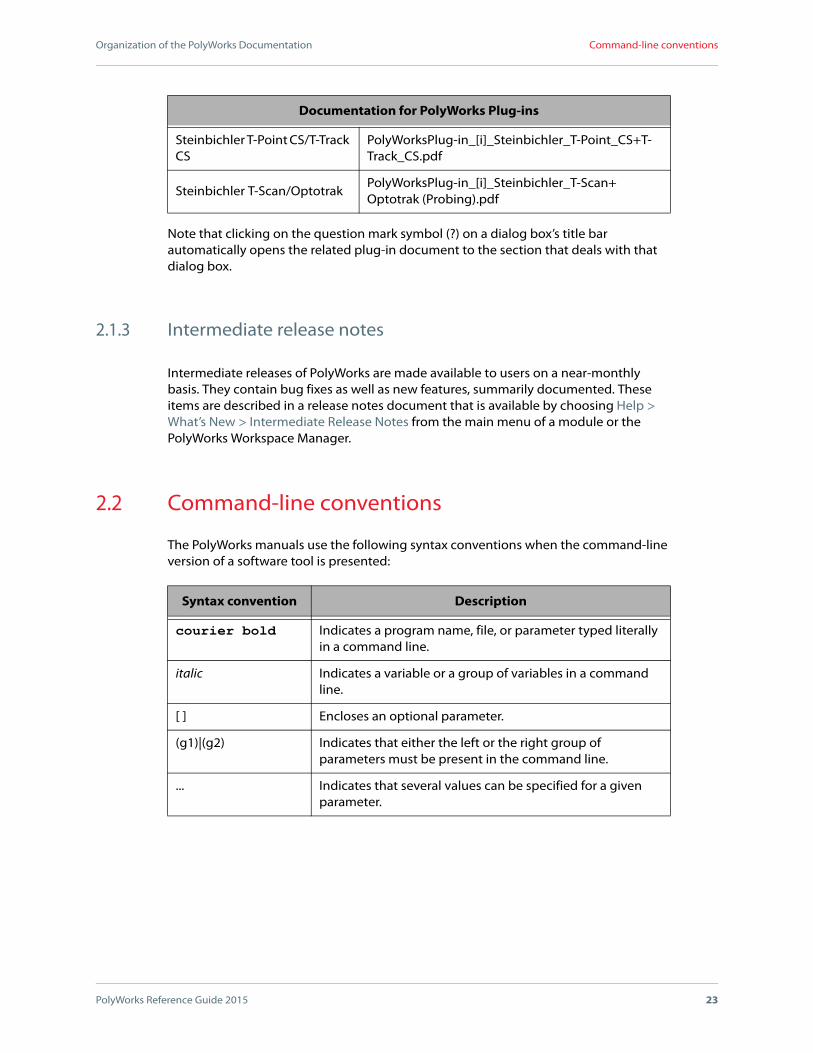
2.1.2 Documentation for plug-ins
Documentation is available for PolyWorks line scanning plug-ins that are offered on the Tools > Plug-ins submenu as well as probing plug-ins offered on IMInspect module’s Probing Device toolbar.
Generic content for probing and line scanning is provided in the Probing chapter of the IMInspect Reference Guide and the Scanning Objects chapter of the IMInspect Reference Guide and the IMAlign Reference Guide.
Custom documents are available for most plug-ins, except third-party plug-ins. Typical content includes requirement and configuration information as well as descriptions of custom (i.e., proprietary) dialog box parameters. The custom documents are listed in the table that follows.
Documentation for PolyWorks Plug-ins
Line Scanning Plug-ins Custom Document (PDF)
(a) Found on the menu offered by the Scan split button located on the Main Objects toolbar in IMInspect and the Processes toolbar in IMAlign
Faro Laser Line Probe PolyWorksPlug-in_[ai]_Faro_Laser_Line_Probe.pdf
Faro 3D Imager PolyWorksPlug-in_[a]_Faro_3D_Imager.pdf
Hexagon PC-DMIS Scanning PolyWorksPlug-in_[ai]_PC_DMIS_Scanning.pdf
Konica Minolta RANGE7 (64-bit only)
PolyWorksPlug-in_[ai]_Konica_Minolta_RANGE7.pdf
Konica Minolta > VIVID 900/910
PolyWorksPlug-in_[ai]_Konica_Minolta_VIVID_900_and_910.pdf
Leica T-Scan/Tracker PolyWorksPlug-in_[ai]_Leica_T-Scan+Tracker.pdf
NDI ScanTRAK PolyWorksPlug-in_[ai]_NDI_ScanTRAK.pdf
Nikon Metrology ScannerPolyWorksPlug-in_[ai]_Nikon_Metrology_Scanner.pdf
Nikon Metrology Laser RadarPolyWorksPlug-in_[i]_Nikon_Metrology_Laser_Radar.pdf
Perceptron Contour ProbePolyWorksPlug-in_[ai]_Perceptron_Contour_Probe.pdf
Perceptron xyz PolyWorksPlug-in_[ai]_Perceptron_xyz.pdf
PolyWorks Line Scanner Simulator
PolyWorksPlug-in_[ai]_PolyWorks_Line_Scanning_Simulator.pdf
Romer Absolute Arm Scanning Peripheral (RS1...)
PolyWorksPlug-in_[ai]_Romer_Absolute_Arm_Scanning_Peripheral.pdf

Organization of the PolyWorks Documentation
PolyWorks Reference Guide 2015 22
List of available manuals
Romer G-Scan/R-Scan PolyWorksPlug-in_[ai]_Romer_G-Scan+R-Scan.pdf
Steinbichler L-Scan/CMMPolyWorksPlug-in_[ai]_Steinbichler_L-Scan+CMM.pdf
Steinbichler Probe ScannerPolyWorksPlug-in_[ai]_Steinbichler_Probe_Scanner.pdf
Steinbichler T-Scan/OptotrakPolyWorksPlug-in_[ai]_Steinbichler_T-Scan+Optotrak (Scanning).pdf
Steinbichler T-Scan CS/T-Track CS
PolyWorksPlug-in_[ai]_Steinbichler_T-Scan_CS+T-Track_CS.pdf
Probing device plug-ins offered on IMInspect’s Probing Device toolbar
Custom Document (PDF)
API Laser Tracker PolyWorksPlug-in_[i]_API_Laser_Tracker.pdf
API Omnitrac 2 Laser TrackerPolyWorksPlug-in_[i]_API_Omnitrac_2_Laser_Tracker.pdf
CimCore Arm PolyWorksPlug-in_[i]_CimCore_Arm.pdf
Faro Arm PolyWorksPlug-in_[i]_Faro_Arm.pdf
Faro Laser Tracker PolyWorksPlug-in_[i]_Faro_Laser_Tracker.pdf
Geodetic V-STARS PolyWorksPlug-in_[i]_Geodetic_V-STARS.pdf
I++ CMM PolyWorksPlug-in_[i]_I++_CMM.pdf
Leica AT400 Laser TrackerPolyWorksPlug-in_[i]_Leica_AT400_Laser_Tracker.pdf
Leica AT960/AT930 Laser Tracker
PolyWorksPlug-in_[i]_Leica_AT960+AT930_Laser_Tracker.pdf
Leica Laser Tracker PolyWorksPlug-in_[i]_Leica_Laser_Tracker.pdf
Leica TDRA6000 PolyWorksPlug-in_[i]_Leica_TDRA6000.pdf
Manual CMM PolyWorksPlug-in_[i]_Manual_CMM.pdf
Metronor Optical TrackerPolyWorksPlug-in_[i]_Metronor_Optical_Tracker.pdf
Nikon Metrology Probe PolyWorksPlug-in_[i]_Nikon_Metrology_Probe.pdf
Perceptron ScanWorks PolyWorksPlug-in_[i]_Perceptron_ScanWorks.pdf
PolyWorks Probe SimulatorPolyWorksPlug-in_[i]_PolyWorks_Probe_Simulator.pdf
Romer Absolute Arm PolyWorksPlug-in_[i]_Romer_Absolute_Arm.pdf
Romer GDS Arm (32-bit) PolyWorksPlug-in_[i]_Romer_GDS_Arm.pdf
Documentation for PolyWorks Plug-ins
Organization of the PolyWorks Documentation
PolyWorks Reference Guide 2015 23
Command-line conventions
Note that clicking on the question mark symbol (?) on a dialog box’s title bar automatically opens the related plug-in document to the section that deals with that dialog box.
2.1.3 Intermediate release notes
Intermediate releases of PolyWorks are made available to users on a near-monthly basis. They contain bug fixes as well as new features, summarily documented. These items are described in a release notes document that is available by choosing Help > What’s New > Intermediate Release Notes from the main menu of a module or the PolyWorks Workspace Manager.
2.2 Command-line conventions
The PolyWorks manuals use the following syntax conventions when the command-line version of a software tool is presented:
Steinbichler T-Point CS/T-Track CS
PolyWorksPlug-in_[i]_Steinbichler_T-Point_CS+T-Track_CS.pdf
Steinbichler T-Scan/OptotrakPolyWorksPlug-in_[i]_Steinbichler_T-Scan+Optotrak (Probing).pdf
Syntax convention Description
courier bold Indicates a program name, file, or parameter typed literally in a command line.
italic Indicates a variable or a group of variables in a command line.
[ ] Encloses an optional parameter.
(g1)|(g2) Indicates that either the left or the right group of parameters must be present in the command line.
... Indicates that several values can be specified for a given parameter.
Documentation for PolyWorks Plug-ins
Organization of the PolyWorks Documentation
PolyWorks Reference Guide 2015 24
Terminology used to describe user interfaces
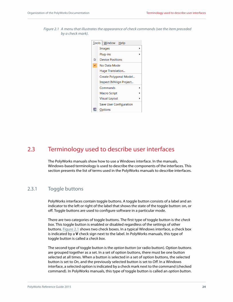
2.3 Terminology used to describe user interfaces
The PolyWorks manuals show how to use a Windows interface. In the manuals, Windows-based terminology is used to describe the components of the interfaces. This section presents the list of terms used in the PolyWorks manuals to describe interfaces.
2.3.1 Toggle buttons
PolyWorks interfaces contain toggle buttons. A toggle button consists of a label and an indicator to the left or right of the label that shows the state of the toggle button: on, or off. Toggle buttons are used to configure software in a particular mode.
There are two categories of toggle buttons. The first type of toggle button is the check box. This toggle button is enabled or disabled regardless of the settings of other buttons. Figure 2.1 shows two check boxes. In a typical Windows interface, a check box is indicated by a V check sign next to the label. In PolyWorks manuals, this type of toggle button is called a check box.
The second type of toggle button is the option button (or radio button). Option buttons are grouped together as a set. In a set of option buttons, there must be one button selected at all times. When a button is selected in a set of option buttons, the selected button is set to On, and the previously selected button is set to Off. In a Windows interface, a selected option is indicated by a check mark next to the command (checked command). In PolyWorks manuals, this type of toggle button is called an option button.
Figure 2.1 A menu that illustrates the appearance of check commands (see the item preceded by a check mark).

Organization of the PolyWorks Documentation
PolyWorks Reference Guide 2015 25
Terminology used to describe user interfaces
2.3.2 List boxes, text boxes, and combo boxes
In a Windows interface, lists are displayed within a list box. Each line in a list box can be manually selected or deselected using standard Windows list box manipulations. A scroll bar to the right of the list is used to move within the window when the number of items is too large for the window size. In PolyWorks manuals, a control displaying a list is called a list box.
A text field in which a parameter value can manually be typed is called a text box.
PolyWorks interfaces also feature a special kind of editing box that combines a text box and a list, called a combo box. In a combo box, clicking the menu to the right of the text box accesses a set of predefined options. When an item in the combo box menu is
Figure 2.2 Several types of controls offered in PolyWorks.
Tabs
List box
Text box
2 combo boxes

Organization of the PolyWorks Documentation
PolyWorks Reference Guide 2015 26
Terminology used to describe user interfaces
selected, the item’s text is transferred to the text box. The combo box text field can be editable or not. Combo boxes are native interfaces in Windows. If a value cannot be entered manually, the editing box is referred to as a list box.
See Figure 2.2 for an example of these types of controls.
2.3.3 Tab interfaces
Tab controls allow multiple interfaces to use the same screen area. To access a particular interface, click a tab. In Figure 2.2, Visualization is a tab control.

3
PolyWorks Reference Guide 2015 27
The PolyWorks Workspace Manager
The PolyWorks Workspace Manager provides direct access to all PolyWorks modules, installs software license keys, offers documentation, and configures file format translators. It also manages files and projects.
This chapter describes the PolyWorks Workspace Manager and offers a description of the workspace format and the PolyWorks Workspace Manager interface.
The PolyWorks Workspace Manager
PolyWorks Reference Guide 2015 28
Introducing the PolyWorks Workspace Manager
3.1 Introducing the PolyWorks Workspace Manager
The PolyWorks Workspace Manager, shown in Figure 3.1, manages a PolyWorks process from beginning to end. This includes the following tasks:
Manages all the incoming data files and the results produced by the PolyWorks modules. As work progresses, files and projects are saved to a container called a workspace. Sharing this work is as easy as sharing the workspace. In addition, objects may be exported from a workspace, with the exception of IMEdit and IMInspect projects.
Offers effective tools for documenting a project.
3.1.1 Starting the PolyWorks Workspace Manager
There are several ways to start the PolyWorks Workspace Manager.
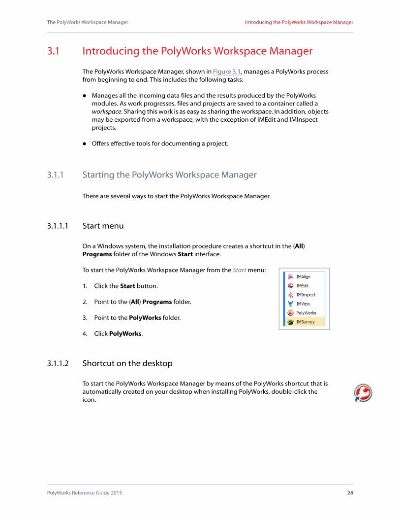
3.1.1.1 Start menu
On a Windows system, the installation procedure creates a shortcut in the (All) Programs folder of the Windows Start interface.
To start the PolyWorks Workspace Manager from the Start menu:
1. Click the Start button.
2. Point to the (All) Programs folder.
3. Point to the PolyWorks folder.
4. Click PolyWorks.
3.1.1.2 Shortcut on the desktop
To start the PolyWorks Workspace Manager by means of the PolyWorks shortcut that is automatically created on your desktop when installing PolyWorks, double-click the icon.

The PolyWorks Workspace Manager
PolyWorks Reference Guide 2015 29
Introducing the PolyWorks Workspace Manager
3.1.1.3 Windows Explorer
To start the PolyWorks Workspace Manager through Windows Explorer, double-click a .pwk or a .pwzip file in Windows Explorer.
Figure 3.1 The PolyWorks Workspace Manager interface.

The PolyWorks Workspace Manager
PolyWorks Reference Guide 2015 30
Introducing the PolyWorks Workspace Manager
3.1.1.4 Command line
To start the PolyWorks Workspace Manager from the command line, give a command that has the following syntax:
polyworks pwk_name [-macro [path]macro_name [argument1...]]
The -macro parameter can be invoked to specify a macro_name to run on starting PolyWorks. Arguments can also be provided on the command line. If no path is specified, a search for a macro of the specified macro_name will be performed, in order, at the following four locations:
The application’s current visual layout.
The workspace associated with the application.
The user’s configuration folder, which is defined as:
[user configuration folder]\.innovmetric.[version]\macro\ApplicationName\
The user’s configuration folder is specified by the User configuration option on the General page of the PolyWorks Workspace Manager Options dialog box.
The PolyWorks system configuration folder, which is defined as:
[PolyWorks installation folder]\macro\ApplicationName\
Starting the PolyWorks Workspace Manager displays two windows:
The first window is a splash screen that presents copyright information, and is displayed for a few seconds.
The second window is the PolyWorks Workspace Manager interface.

The PolyWorks Workspace Manager
PolyWorks Reference Guide 2015 31
Introducing the PolyWorks Workspace Manager
3.1.2 Introducing the workspace format
The PolyWorks Workspace Manager uses a workspace format which is designed to handle all the results of a point cloud processing project. One workspace should be created for each point cloud processing project.
A workspace is composed of one XML file with the .pwk extension and one folder with the _Files suffix. For example: workspace 1.pwk and workspace 1_Files. When a workspace is created, a .pwk file is specified and the folder is created automatically. Both file and folder are managed by the PolyWorks Workspace Manager.
The workspace folder contains the following directories:
The wm-data folder contains all the results generated by a PolyWorks process, including:
IMInspect project directories
IMEdit project directories
IMAlign project directories
IMSurvey project directories
Polygonal models, including those generated by IMMerge and IMCompress
The workspace folder can also contain all the incoming point cloud files imported in PolyWorks, to generate completely self-contained workspaces.
Note that projects are saved to subfolders whose names are system generated; if your project’s name is project1, it is saved to a subfolder with a name other than project1.
The Macro folder is created when a macro script is saved to the workspace. The folder contains all the macro scripts saved to the workspace.
The User-data folder is an empty folder to which the user can save files. The Window > User-Data Folder command opens this folder in a file browser. As a general rule, there is no reason to browse the folder structure of a workspace folder.
When sharing a workspace, it is possible to add extra files, like images and text documents related to the project, to the user-data folder before compressing the workspace. The person receiving the compressed workspace opens it in the PolyWorks Workspace Manager, and after specifying where to decompress the workspace, it is opened in the PolyWorks Workspace Manager. Any files added manually to the folder do not appear in the workspace in the PolyWorks Workspace Manager, but can be found using the Window > User-Data Folder command.
The Visual_layout folder is created when a visual layout is saved to the workspace.

The PolyWorks Workspace Manager
PolyWorks Reference Guide 2015 32
Introducing the PolyWorks Workspace Manager
The workspace .pwk file is a description file that describes the contents of the workspace folder and contains project documentation. In addition, it keeps track of what objects are used in one or more projects. For example, ten point clouds may be used in an IMAlign project, and the IMAlign project may be used in an IMInspect project. As soon as a change is made to a workspace, the description file is updated. The last four versions of the description file are automatically saved to a folder (i.e., WorkspaceName_Files\wm-data\xdata\pwkBackup); if for any reason the current description file becomes corrupt, the user has access to previous versions, which may be helpful in accessing the workspace. A backup version of the description file would need to be copied to the same level as the Workspace_Files folder.
Objects used by a project are referred to as dependent objects. Dependency information is used by several operations. For example:
A dependent object cannot be deleted. When attempting to do so, the PolyWorks Workspace Manager informs the user that the object is used in a project, and that it cannot be deleted.
When copying a project with dependent objects to another workspace, the PolyWorks Workspace Manager automatically includes all of the dependent objects in the copy operation.
When trying to open an IMAlign project used in another project, the PolyWorks Workspace Manager displays a message box that informs the user that modifying the project can affect the specified projects, and offers three options: Open anyway, Open a copy, or Cancel the operation.
Dependent objects used by an open module are locked and flagged with a special icon:
PolyWorks projects opened in the module with which they were created are flagged with a padlock on a red background. These projects can be modified but they can only be used by one module at a time.
PolyWorks projects opened in a module other than the module in which they were created (e.g., an IMAlign project opened in the IMInspect module) are flagged with a padlock on a blue background. These objects can be used by more than one module at a time, but cannot be modified.
All other objects found in the PolyWorks Workspace Manager tree view (i.e., polygonal models and point clouds) that are used by a project that is opened in any module are flagged with a blue padlock. These objects can be used by more than one module at a time, but cannot be modified.
See Figure 3.3 for an example of a locked object. Locked objects can be copied to other workspaces, but they cannot be pasted or deleted.
3.1.2.1 Using workspaces with directories managed by cloud storage services
Using workspaces with directories managed by cloud storage services can lead to data loss and corruption. It is therefore blocked or limited in the following instances:
The PolyWorks Workspace Manager
PolyWorks Reference Guide 2015 33
Introducing the PolyWorks Workspace Manager
Opening a workspace is done in read-only mode, which prevents editing it.
Saving a workspace is blocked. This includes the following cases:
Saving a project from a module, when the current workspace has never been saved, is blocked.
Saving a project from a module in a different workspace than the current one is blocked if the destination workspace is in a cloud folder.
The cloud storage services detected are Google Drive, Dropbox, and Microsoft OneDrive.
Note that using a cloud storage service as a default folder is not recommended.
3.1.3 The Open or Create Workspace dialog box
The Open or Create Workspace dialog box is shown in Figure 3.2. An option on the Display page of the PolyWorks Workspace Manager Options dialog box is available that enables opening the dialog box on startup of the PolyWorks Workspace Manager; for more information, see Section 3.7.8.2 Display options. The dialog box allows opening an existing workspace or creating a new workspace.
This dialog box allows the following operations:
Create a new workspace. The default location is in ...\My Documents\PolyWorks.
Select one or more recently opened workspaces, and open them.
Browse an existing workspace on disk.
To not use any of the preceding functions, press the Cancel button. A Never show this dialog box again check box is also available. It disables the dialog box display option.

The PolyWorks Workspace Manager
PolyWorks Reference Guide 2015 34
Introducing the PolyWorks Workspace Manager
Figure 3.2 The Open or Create Workspace dialog box can be configured to open at the startup of the PolyWorks Workspace Manager.

The PolyWorks Workspace Manager
PolyWorks Reference Guide 2015 35
Introducing the PolyWorks Workspace Manager
3.1.4 Organization of the PolyWorks Workspace Manager interface
As shown in Figure 3.3, the PolyWorks Workspace Manager user interface offers a menu bar, a Standard toolbar, a Modules toolbar, and a central work area divided into two sections. The section on the left is the Workspaces pane - a tree view where each object is represented by an item. The section on the right is the Properties pane.
3.1.4.1 The Workspaces area
The Workspaces pane to the left of the interface manages multiple workspaces and the open modules associated with each workspace. The area works as follows:
There is one button per workspace. To view its properties, hold the pointer over the workspace button a few seconds. This is useful when the Properties pane is hidden.
Only one workspace is active at a time. The active workspace is the one that has a tree view displayed below its button.
The tree view displays the workspace contents saved by the PolyWorks Workspace Manager, and contains the following branches:
IMInspect Projects
IMEdit Projects
IMAlign Projects
IMSurvey Projects (Not always present. It depends on the Application mode setting.)
Polygonal Models
Point Clouds: Contains the incoming point clouds copied by the PolyWorks Workspace Manager to the workspace as a result of a PolyWorks operation (e.g., opening or importing an IMAlign project on disk will copy the project under the IMAlign Projects branch and the files used by the project to the Point Clouds branch).
IMTexture Input Files: Contains .imN files saved by IMCompress for use in IMTexture.
The displayed items are objects. They can be selected, copied, and pasted, or dragged and dropped, on:
The active workspace or an open workspace’s button
Module icons on the toolbar

The PolyWorks Workspace Manager
PolyWorks Reference Guide 2015 36
Introducing the PolyWorks Workspace Manager
Open module interfaces
Open modules listed in a workspace (see Section 3.5 Editing workspace objects for more information)
The order of items within a branch can be modified by dragging single objects; when dragged upward, the object in question is placed above the object currently under the pointer, and when dragged downward, it is placed below the object currently under the pointer.
Shortcut menus are available for selected objects and their branches.
The Properties pane to the right also uses the tree view selection.
Figure 3.3 The PolyWorks Workspace Manager interface.
Menu bar
Standard toolbar
Workspaces pane:
• Active workspace
• Tree view
• Locked (padlock) objects – used by an open module
• Modules open in the active workspace
• A button for each open workspace
Properties pane: offers object properties for the selected object (e.g., name, notes, last view).
Status bar
Modules toolbar

The PolyWorks Workspace Manager
PolyWorks Reference Guide 2015 37
Introducing the PolyWorks Workspace Manager
3.1.4.2 The Properties pane
The Properties pane is located to the right of the Workspaces pane. It displays properties and documentation, including notes and a view for the object selected in the active workspace. The Properties pane can be closed/opened like any other dockable pane. It is mostly useful when a single object is selected in the active workspace. Users may then:
View the selected object’s name as well as its date of creation and most recent modification.
Press Edit to write specific information about the object.
See a Preview Image for IMAlign, IMEdit, IMInspect, and IMSurvey projects. This is a snapshot of the 3D scene that is automatically taken on saving and exiting a PolyWorks module.
To obtain a fixed preview image (i.e., one that does not change on saving a project), prepare the 3D scene and choose the Window > Capture Project Preview Image command.
Note that the image can be dragged onto your desktop and saved as a .jpg file. Also, the most recent image becomes the thumbnail of the workspace .pwk file.
3.1.4.3 The main menu bar
The PolyWorks Workspace Manager’s menu bar offers the following menu items:
Menu Description
File Offers operations to open, create, and close workspaces, and operations that allow importing objects into a workspace and exporting objects from a workspace.
Edit Offers standard operations for copying and pasting objects between workspaces as well as a workspace search tool.
View Offers an item that allows displaying the Properties pane.
Tools
Allows installing license keys, configuring PolyWorks and the PolyWorks Workspace Manager using an options dialog box, and controlling the display of the Windows command prompt as well as the Macro Script Editor pane that is used to create macro scripts (see Section 3.10.1 Displaying the Macro Script Editor). This menu also allows specifying a visual layout.
Window Allows specifying the active workspace from a list of open workspaces, and opens the user-data folder browser.
The PolyWorks Workspace Manager
PolyWorks Reference Guide 2015 38
Introducing the PolyWorks Workspace Manager
3.1.4.4 The Modules toolbar
The PolyWorks Workspace Manager’s Modules toolbar offers a button for each PolyWorks main module. Note that the IMInspect and the IMInspect Probing buttons are not offered on the toolbar at the same time; rather, a menu beside the button displayed (e.g., IMInspect) allows choosing the other, nondisplayed button (e.g., IMInspect Probing). Each button icon represents its module’s first meaningful letter:
3.1.4.5 Customizing the user interface
Many elements of the PolyWorks Workspace Manager’s graphical user interface (e.g., docking windows, menus, toolbars) can be customized. In addition, the Tools > Visual Layout submenu contains commands that allow loading and saving visual layouts, and importing macro scripts from layouts. For complete information on customizing visual layouts, see Chapter 4 Customizing the Graphical User Interface.
3.1.5 Hidden shortcuts
The shortcuts in the table that follows do not have equivalent commands on any menus.
Help Gives access to all of the software documentation as well as information concerning the current version of PolyWorks.
Module Letter Icon Module Letter Icon
IMAlign A IMInspect I
IMMerge MIMInspect
ProbingI
IMEdit E IMSurvey S
Shortcut Description
CTRL+TAB Cycles through the open workspaces.
CTRL+1 to CTRL+9 Makes the specified open workspace the active workspace.
Menu Description

The PolyWorks Workspace Manager
PolyWorks Reference Guide 2015 39
Manipulating workspaces
3.2 Manipulating workspaces
3.2.1 Creating workspaces
To create a new workspace, choose the File > New command. An untitled workspace is immediately created. The objects in an untitled workspace are not actually saved until the workspace itself is saved and given a name. Once a workspace has a name, any changes made to it, such as adding or removing objects, are automatically saved.
3.2.2 Opening workspaces
There are several ways to open a workspace:
To open a recent workspace:
Choose the File > Recent Workspaces command and choose a workspace in the list that is displayed.
To open one or more workspaces:
Choose the File > Open command. A file browser is displayed. The Files of type list box allows filtering the files displayed by the browser. It offers the following choices: All Workspace Files (*.pwk, *.pwzip), All Files (*.*), Compressed Workspace Files (*.pwk, *.pwzip), and Workspace Files (*.pwk). Choose one or more .pwk and/or *.pwzip files and press the Open button.
To open a workspace from Windows Explorer:
Double-click a .pwk or a .pwzip file in Windows Explorer.
Note that it is possible to open a workspace already in use by another user. When opening a workspace locked by another PolyWorks Workspace Manager, a message is displayed specifying the user name and the computer on which the workspace is currently opened, and asking to import the objects from the workspace in the new PolyWorks Workspace Manager. On clicking Yes, a dialog box is displayed that allows selecting the objects to import; if the current workspace is untitled and empty, the copy of the objects are imported into it, otherwise, they are imported into a new, untitled workspace. On clicking No, the operation ends.
If a file associated with the workspace folder is missing, the dialog box shown in Figure 3.4 is displayed. The name of the missing file is indicated in the first text box. A new path to the file may be specified directly in the second text box, or using the Browse button to locate the file. Then, press the OK button. Or, if more than one file is missing, you may press the Skip button and the workspace will be loaded without the files. Note

The PolyWorks Workspace Manager
PolyWorks Reference Guide 2015 40
Manipulating workspaces
that when the OK button is pressed without a path specified, the workspace is loaded without the missing files. If the Cancel button is pressed, an empty workspace opens.
Because of important changes in the PolyWorks software between versions, it may not be possible to open successfully a workspace that was saved with a later version of PolyWorks. As a result, appropriate warning messages are displayed in this situation to inform the user. It may be preferable to open a copy of such a workspace to evaluate data loss, if any. Furthermore, if a workspace is opened with an earlier version of PolyWorks and saved, and then opened in a later version of PolyWorks, not all of the original information may be recuperated; again, appropriate warnings are displayed to that effect to inform the user.
Some restrictions apply when using a workspace in a folder managed by a cloud storage service. For more information, see Section 3.1.2.1 Using workspaces with directories managed by cloud storage services.
3.2.3 Sharing workspaces
Workspaces can easily be shared with colleagues. The PolyWorks Workspace Manager offers an operation that compresses the .pwk file and the associated folder into one file with the .pwzip extension.
The PolyWorks Workspace Manager can open a .pwzip file. It is first decompressed to a specified folder and then read into the PolyWorks Workspace Manager. For more information on compressing workspaces, see Section 3.6.1 Exporting compressed workspaces.
Figure 3.4 The dialog box that is displayed when importing a standalone IMAlign project and the PolyWorks Workspace Manager cannot find a file used by the project.
The PolyWorks Workspace Manager
PolyWorks Reference Guide 2015 41
Manipulating workspaces
3.2.4 Closing workspaces
To close the active workspace, choose the File > Close command, or right-click over the workspace in the active workspace area and click Close on the shortcut menu.
To close an open workspace, right-click over the workspace button in the Workspaces pane and click Close on the shortcut menu.
The PolyWorks Workspace Manager proceeds as follows when closing a workspace:
If no modules are open for the workspace, it is closed.
If modules are open and contain no unsaved changes, the modules are closed and then the workspace is closed.
If any open modules have unsaved data, a message window is displayed that lists the modules and offers a Save All button that saves changes in all related modules. On pressing this button, the PolyWorks Workspace Manager closes the modules and the workspace. Press the Cancel button to cancel the operation. See Figure 3.13 (a).
If any open modules are processing data, a message window is displayed that lists those modules and explains that processing must be complete before a workspace can be closed. Press the OK button to dismiss the window. See Figure 3.13 (b).
Note that when the PolyWorks Workspace Manager closes an untitled workspace, it queries to save the workspace. You may press the Yes button and provide a name in the file browser that is displayed, press the No button and lose the data in the workspace, or press the Cancel button to end the operation.
3.2.5 Controlling the visibility of open modules
To control the visibility of open modules, right-click over a workspace button and click one of the following commands on the shortcut menu:
Maximize Open Modules
Maximizes all the open modules of the active workspace.
Minimize Open Modules
Minimizes all the open modules of the active workspace.
3.2.6 Accessing a workspace’s User-Data folder
The Window > User-Data Folder command opens the Windows Explorer in the user-data folder of the active workspace.

The PolyWorks Workspace Manager
PolyWorks Reference Guide 2015 42
Saving workspaces
As mentioned in the introduction, this folder is for the user’s convenience. It may be used to store other files relevant to the workspace, such as text files and spreadsheets.
WARNING: Do not use the Explorer to browse the wm-data folder and move or rename files, or perform similar operations. This would corrupt the workspace. The files in that folder should only be manipulated by way of the PolyWorks Workspace Manager.
3.3 Saving workspaces
When performing an action in a module that changes the contents of a named workspace, such as saving a project or importing an object, the changes made to the workspace are automatically saved. To remove a workspace from the Workspaces area, it may be closed.
If the workspace is untitled, and a new project is saved to it using an instance of a module, the PolyWorks Workspace Manager provides dialog boxes that allow first naming the workspace and then completing the save operation. In other cases, such as generating a polygonal model using IMMerge, the new mesh can be written to an untitled workspace. A workspace may be saved using the File > Save as command. On choosing the command, the New Workspace file browser is displayed. Specify a file name and location. When attempting to close an untitled workspace with unsaved data, a confirmation window informs the user of the situation and offers to save the workspace. Press the Yes button and the New Workspace file browser is displayed to name the workspace and save its contents. Press the No button and the contents are lost and cannot be retrieved.
Some restrictions apply when using a workspace in a folder managed by a cloud storage service. For more information, see Section 3.1.2.1 Using workspaces with directories managed by cloud storage services.

The PolyWorks Workspace Manager
PolyWorks Reference Guide 2015 43
Importing objects from other workspaces or from disk
3.4 Importing objects from other workspaces or from disk
In the PolyWorks Workspace Manager, objects can be imported in two ways:
To import an object, choose a command on the File > Import menu.
Right-click over the branch of a type of object in the active workspace and click Import on the shortcut menu.
Choosing an import command displays the file browser shown in Figure 3.5. Files can be selected in folders or within PolyWorks workspaces. To quickly locate the PolyWorks workspaces, two shortcuts are offered in the left part of the browser (see Figure 3.5 (a)):
Open Workspaces: Contains a shortcut for each workspace that is currently open in PolyWorks. This shortcut points to a subfolder (called Open Workspaces) of the PolyWorks folder.
PolyWorks: Contains the above-mentioned folder (Open Workspaces) and the list of all workspaces previously saved in the PolyWorks subfolder.
Figure 3.5 The file browser used to import files from folders and PolyWorks workspaces.
(a) Browse in open workspaces, or workspaces in the PolyWorks folder.
(b) File type filter.

The PolyWorks Workspace Manager
PolyWorks Reference Guide 2015 44
Importing objects from other workspaces or from disk
Multiple file selection is possible and a file type filter is offered (see Figure 3.5 (b)).
See the following sections for information on the commands used to import objects from the File > Import menu.
3.4.1 Importing point clouds
Point clouds can be imported from workspaces using the File > Import > Point Clouds command, or from disk by using the Import via IMAlign, Import via IMInspect, and Import via IMSurvey operations available from the Point Clouds branch’s menu. In both cases, a file browser similar to the one shown in Figure 3.5 is displayed. Note that, when importing using the IMAlign, IMInspect, or IMSurvey modules, the file browser is displayed in the selected module. Once the file selection is made, press the Open button to launch the import operation.
If you are importing using IMAlign, IMInspect, or IMSurvey, refer to the module’s documentation (i.e., IMAlign Reference Guide, IMInspect Reference Guide, IMSurvey Reference Guide) for complete information on importing point clouds, especially regarding import options that may be offered. Note the following particularities:
The aforementioned modules offer the Keep external to workspace option, which is useful when importing a file that is very large, or shared among several users. When a file is kept external, an object is still created in the workspace, but its data is not copied to the workspace folder. Rather, the workspace object points to the original
file on the disk, and the object icon has a special symbol superimposed onto it. When compressing a workspace that contains external files, a copy is not automatically included in the .pwzip compressed file. Instead, a dialog box is displayed asking to include a copy of the external files. See Section 3.6.1 Exporting compressed workspaces for more information.
In the case of ASCII or PTX files imported by way of the IMAlign module, the file browser offers a Georeferenced file check box. The PolyWorks Workspace Manager flags each file internally as being georeferenced or not georeferenced. A file that is georeferenced is one with coordinates in large numbers. This information is used when importing the file in IMAlign. It is not used, however, when importing the file in IMInspect. For more information, see the IMAlign Reference Guide.
Once the point cloud has been imported, it is saved under the Point Clouds branch of the active workspace. If the point cloud has been imported using a module, it may then be closed without saving the project.
3.4.2 Importing polygonal models
The File > Import > Polygonal Models command allows importing one or more polygonal models. .

The PolyWorks Workspace Manager
PolyWorks Reference Guide 2015 45
Importing objects from other workspaces or from disk
On choosing the File > Import > Polygonal Modelscommand, a file browser similar to the one shown in Figure 3.5 is displayed to specify polygonal model files. The table that follows provides the list of supported file formats.
By default, all polygonal model files are viewed. However, a filter may be set for the browser window using a list box.
Note that if the file is imported from disk and it does not have the correct file extension (e.g., .abc), this is detected on opening the file, and a dialog box displays (see Figure 3.6), which offers all available formats. Choose the correct format and then press the OK button.
Polygonal models are saved to the Polygonal Models branch of the tree view.
Supported Polygonal Model Formats
CNRC files (*.cnrc)DirectModel JT files (*.jt)InnovMetric PQK files (*.pqk)InnovMetric POL files (*.pol)Nastran NAS files (*.nas)PLY files (*.ply)
Polygonal models in workspaces (*.pwk; *.pwzip; *.pwkpm)STL ASCII files (*.stla)STL binary files (*.stlb)STL files (*.stl)VRML files (*.wrl)Wavefront OBJ files (*.obj)
Figure 3.6 If the file type cannot be determined, a file type may be specified using the dialog box shown here.

The PolyWorks Workspace Manager
PolyWorks Reference Guide 2015 46
Importing objects from other workspaces or from disk
3.4.3 Importing projects
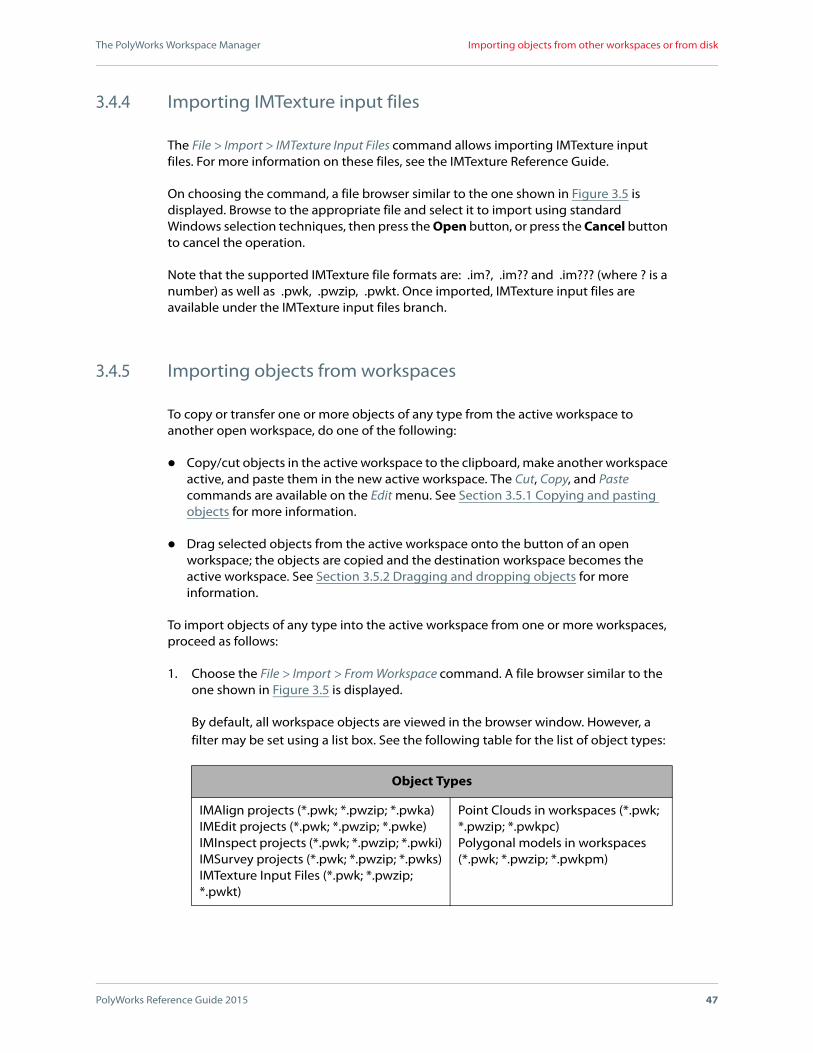
The File > Import > Projects command allows importing IMAlign, IMEdit, IMInspect, and IMSurvey projects. On choosing the command, a file browser similar to the one shown in Figure 3.5 is displayed. Browse to the appropriate workspace and select the project to import using standard Windows selection techniques. If the browser preview pane is displayed, the preview image of the selected project appears in the right part of the browser. Press the Open button, or press the Cancel button to cancel the operation.
Note the following with respect to importing projects:
IMEdit projects are imported under the IMEdit Projects branch. No other objects are added to the workspace.
IMAlign projects are imported under the IMAlign Projects branch and their associated original point cloud files or, in certain cases, extracted 3D image files (*.pf ), are copied to the Point Clouds branch.
When importing an IMAlign project from disk, browse the project folder and select the .info file. If a file associated with the IMAlign project folder is missing, the dialog box shown in Figure 3.7 is displayed. The name of the missing file is indicated in the first text box. A new path to the file may be specified in the second text box manually or by pressing the Browse button and locating the missing file; pressing the OK button launches the import operation. If the file cannot be located, the project may be loaded without the file by pressing the Skip button.
Figure 3.7 The dialog box that is displayed when importing a standalone IMAlign project and the PolyWorks Workspace Manager cannot find a file used by the project.
The PolyWorks Workspace Manager
PolyWorks Reference Guide 2015 47
Importing objects from other workspaces or from disk
3.4.4 Importing IMTexture input files
The File > Import > IMTexture Input Files command allows importing IMTexture input files. For more information on these files, see the IMTexture Reference Guide.
On choosing the command, a file browser similar to the one shown in Figure 3.5 is displayed. Browse to the appropriate file and select it to import using standard Windows selection techniques, then press the Open button, or press the Cancel button to cancel the operation.
Note that the supported IMTexture file formats are: .im?, .im?? and .im??? (where ? is a number) as well as .pwk, .pwzip, .pwkt. Once imported, IMTexture input files are available under the IMTexture input files branch.
3.4.5 Importing objects from workspaces
To copy or transfer one or more objects of any type from the active workspace to another open workspace, do one of the following:
Copy/cut objects in the active workspace to the clipboard, make another workspace active, and paste them in the new active workspace. The Cut, Copy, and Paste commands are available on the Edit menu. See Section 3.5.1 Copying and pasting objects for more information.
Drag selected objects from the active workspace onto the button of an open workspace; the objects are copied and the destination workspace becomes the active workspace. See Section 3.5.2 Dragging and dropping objects for more information.
To import objects of any type into the active workspace from one or more workspaces, proceed as follows:
1. Choose the File > Import > From Workspace command. A file browser similar to the one shown in Figure 3.5 is displayed.
By default, all workspace objects are viewed in the browser window. However, a filter may be set using a list box. See the following table for the list of object types:
Object Types
IMAlign projects (*.pwk; *.pwzip; *.pwka)IMEdit projects (*.pwk; *.pwzip; *.pwke)IMInspect projects (*.pwk; *.pwzip; *.pwki)IMSurvey projects (*.pwk; *.pwzip; *.pwks)IMTexture Input Files (*.pwk; *.pwzip; *.pwkt)
Point Clouds in workspaces (*.pwk; *.pwzip; *.pwkpc)Polygonal models in workspaces (*.pwk; *.pwzip; *.pwkpm)

The PolyWorks Workspace Manager
PolyWorks Reference Guide 2015 48
Editing workspace objects
2. Click one of the shortcuts in the left part of the file browser, which allow to quickly access the workspaces currently open (Open Workspaces shortcut) or the list of all workspaces previously saved in PolyWorks (PolyWorks shortcut).
3. Press the Open button. The selected objects, along with any dependent objects, will be copied to the active workspace.
When copying/transferring a point cloud from a source workspace to a destination workspace, and the point cloud already exists in the destination workspace, PolyWorks does not create a duplicate of the object if the two objects are identical (i.e., name, size, CRC checksum, visibility status, location status [i.e., internal to workspace, keep external], notes). This way, the size of the workspace is minimized.
3.5 Editing workspace objects
Objects in a workspace can be renamed and deleted, and notes can be added to the object. In addition, objects can be copy/pasted, or dragged, to another workspace.
3.5.1 Copying and pasting objects
Objects selected in the active workspace can be copy/cut to the clipboard using the Copy and Cut commands on the Edit menu. These objects may then be pasted to another workspace by first making it active and then choosing the Edit > Paste command.
If one or more selected objects could not be cut (deleted), a message window is displayed listing them and stating that they have been copied to the clipboard instead. Press the OK button to continue.
3.5.2 Dragging and dropping objects
Objects from an active workspace can be dragged from a workspace, onto the button of another open workspace. The objects are automatically copied in the destination workspace. Note that if a point cloud already exists in the destination workspace, no duplicate will be created.
Objects can also be dragged from the workspace over an open module window or a module icon on the Modules toolbar. However, note the following exceptions regarding objects with dependencies:
IMAlign projects flagged with a padlock cannot be dragged over the IMAlign and IMInspect modules. A message is displayed indicating that the object is locked and cannot be modified.
The PolyWorks Workspace Manager
PolyWorks Reference Guide 2015 49
Editing workspace objects
When opening an IMAlign project used in another project, the PolyWorks Workspace Manager alerts the user to the fact that modifying the project can affect the specified projects, and offers three options:
Choose Open anyway to open the actual project.
Choose Open a copy to open a copy of the project and ensure that the actual project remains unchanged.
Choose Cancel to cancel the operation.
It is also possible to drag certain objects (i.e., Polygonal Models with the .pol and .pqk extensions) from Windows Explorer onto an open workspace. Similarly, an entire workspace with the .pwk extension can be dragged directly from Windows Explorer onto the PolyWorks Workspace Manager.
3.5.3 Deleting objects
The PolyWorks Workspace Manager allows deleting objects that are not locked or dependent, by selecting the objects in the tree view and choosing the Edit > Delete command, or by right-clicking and clicking Delete on the shortcut menu. If the selection contains one or more objects that cannot be deleted, a message window informs the user that not all objects could be deleted.
On deleting certain objects, for example an IMAlign project, other objects, in this case the imported point clouds, may become unused. In this event, a message window similar to the one shown in Figure 3.8 is displayed automatically, offering to delete the objects that are no longer used as a result of deleting certain objects. Press the Yes button to perform the additional delete operation or press the No button to keep the objects.
Unused point clouds can also be deleted using the Delete Unused Datasets operation available from the Point Clouds branch menu. Right-click the Point Clouds branch in the tree view and click Delete Unused Datasets on the shortcut menu. A confirmation window is displayed. Press the Yes button to perform the delete operation or press the No button to cancel the operation.
When objects are deleted from a workspace, they are permanently removed from the disk. They are not transferred to the Windows Recycle Bin either. The exception to this rule are point clouds that were imported using the Keep files external to workspace option.

The PolyWorks Workspace Manager
PolyWorks Reference Guide 2015 50
Editing workspace objects
3.5.4 Renaming objects
The Edit > Rename command allows editing the name of a selected object by changing its name directly in the tree view. The following characters cannot be used in an object name: “/” and “\”.
Note that locked objects as well as point clouds cannot be renamed.
3.5.5 Searching for workspaces
The Edit > Search Workspaces command displays the browser shown in Figure 3.9 that allows searching for workspaces. Several search criteria are available in the area to the left:
The Look in area specifies where and what to search:
Look inA text box that specifies a root folder for a search.
Search subfoldersA check box that enables a recursive search in all subfolders of the root search folder. By default, it is selected.
Search PWZIPA check box that enables including compressed workspaces in the search. By default, it is cleared.
The Workspace search options area allows specifying search criteria that pertain to workspaces:
Figure 3.8 A message window that informs the user that following the deletion of selected objects, other objects in the active workspace have become unused, and offers to delete them as well.
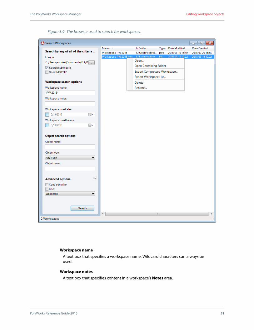
The PolyWorks Workspace Manager
PolyWorks Reference Guide 2015 51
Editing workspace objects
Workspace nameA text box that specifies a workspace name. Wildcard characters can always be used.
Workspace notesA text box that specifies content in a workspace’s Notes area.
Figure 3.9 The browser used to search for workspaces.

The PolyWorks Workspace Manager
PolyWorks Reference Guide 2015 52
Editing workspace objects
Workspace used afterA combo box that specifies a date after which a workspace must have been used (modified). A date appears, which can be directly modified. Or a date may be specified by pressing the combo box arrow and choosing a date in the calendar that is displayed. The date is preceded by a check box. When selected, the date is used as a search criterion.
Workspace used beforeA combo box that specifies a date before which a workspace must have been used (modified); it cannot have been used after the specified date. A date appears, which can be directly modified. Or a date may be specified by pressing the combo box arrow and choosing a date in the calendar that is displayed. The date is preceded by a check box. When selected, the date is used as a search criterion.
The Object search options area allows specifying search criteria that pertain to objects in workspaces:
Object nameA text box that specifies the name of an object.
Object typeA list box that specifies the object type. The choice Any Type includes all of the possible types, while the other choices specify a certain object type (e.g., IMAlign Projects).
Object notesA text box that specifies content in the Notes area of objects.
The Advanced options area allows specifying special search criteria:
Case sensitiveA check box that specifies respecting the case of letters in searches for all text search criteria except the workspace name. By default, it is cleared.
UseA check box that enables a list box which offers two advanced search items that are mutually exclusive: Wildcards (allows the use of the * and ? characters to replace many or one character, respectively) and Regular Expressions (designates a powerful search pattern language that is fully documented in the public domain; also called REGEX). Note that even if the check box is cleared, wildcard characters may be used at all times when specifying a workspace name.
The results are displayed in the area to the right, and include: Name, In Folder, Type, Date Modified, Date Created. Results may be sorted by clicking over column titles. Operations may be performed on displayed workspaces. Right-click a displayed workspace, or a selection of displayed workspaces, to display a shortcut menu that offers the following commands:
Open
Opens the workspaces in the PolyWorks Workspace Manager.

The PolyWorks Workspace Manager
PolyWorks Reference Guide 2015 53
Editing workspace objects
Open Containing Folder
Opens the folder containing the workspace. This command is only offered if a single workspace is selected.
Export Compressed Workspace
If one workspace is selected, specify a file name and location for the new compressed workspace.
If more that one workspace is selected, opens a folder browser to specify a subfolder for the new compressed workspaces.
For complete information, see Section 3.6.1 Exporting compressed workspaces.
Export Workspace List
Exports the path and workspace name of the selected workspaces to a text file. On choosing this command, a file browser is displayed. Specify a file name and location and press the Save button.
Delete
Deletes the entire workspace (the name.pwk file and its name_FILES folder). If a selected workspace is currently open, and has open modules with no unsaved data, the modules will be closed and the workspace deleted. If there are open modules with unsaved data, the operation will not be performed. Once deleted, a workspace cannot be recuperated.
Rename
Renames the workspace file and its corresponding folder. This command is only offered if a single workspace is selected.

The PolyWorks Workspace Manager
PolyWorks Reference Guide 2015 54
Editing workspace objects
3.5.6 Editing an object’s notes
When an object is selected in the tree view, its notes are displayed in the Properties pane. To edit an object’s notes, select it in the tree view and click Edit in the Properties pane, or right-click the object in the tree view and click Edit Notes on the shortcut menu. The dialog box shown in Figure 3.10 is displayed. Edit the contents of the text area and press the OK button to transfer the contents to the application, or press Cancel to end the edit operation.
3.5.7 Editing external objects
The shortcut menu of objects that are external to the workspace offers two operations specific to these objects:
Bring Copy into Workspace
Imports a copy of the selected external objects into the workspace.
Change External File Location
Opens the dialog box shown in Figure 3.11, to specify a new location (i.e., path) for each selected external object. It offers the following items:
Current file name
The complete file name of the first selected external object.
New location
A text box that allows specifying a new location, either manually or by pressing the Browse button and specifying a new path interactively using the folder browser that is displayed.
Figure 3.10 The dialog box used to edit an object’s notes.

The PolyWorks Workspace Manager
PolyWorks Reference Guide 2015 55
Editing workspace objects
Press the Skip button to process the next selected external file; the button is not available if there are no more files to process.
Once a new location has been specified, press the OK button to apply the change, or the Cancel button to cancel the operation. If more than one external object was selected, the name of the next external object is displayed and a new file location may be specified.
Figure 3.11 The dialog box used to change the location of an external object.

The PolyWorks Workspace Manager
PolyWorks Reference Guide 2015 56
Exporting objects and projects
3.6 Exporting objects and projects
3.6.1 Exporting compressed workspaces
A workspace is an XML file that describes the objects in the workspace and a folder that contains the objects in the workspace (except for those external to the workspace). The PolyWorks Workspace Manager allows compressing the file and the folder to one file, which makes sharing it easier and faster:
To compress the active workspace:
1. Choose the File > Export > Compressed Workspace command, or right-click over its workspace button in the Workspaces pane. Click Export Compressed Workspace on the shortcut menu.
2. In the file browser that is displayed, specify a file name and location. The Options button displays the dialog box shown in Figure 3.12 that offers the following item:
Delete source workspaceA check box that allows deleting the source workspace after it has been compressed and saved. By default, the check box is cleared.
Press the OK button to keep the specification or the Cancel button to dismiss the dialog box without keeping any specifications.
3. Press the Save button to launch the export operation, or the Cancel button to stop the operation.
To compress an open workspace:
1. Right-click over its workspace button in the Workspaces pane.
2. Click Export Compressed Workspace on the shortcut menu.
3. In the file browser that is displayed, specify a file name and location. The Options button displays the dialog box shown in Figure 3.12 that offers the following item:
Figure 3.12 Options offered when exporting a compressed workspace.

The PolyWorks Workspace Manager
PolyWorks Reference Guide 2015 57
Exporting objects and projects
Delete source workspaceA check box that allows deleting the source workspace after it has been compressed and saved. By default, the check box is cleared.
Press the OK button to keep the specification or the Cancel button to dismiss the dialog box without keeping any specifications.
4. Press the Save button to launch the export operation, or the Cancel button to stop the operation.
To compress selected objects from a workspace:
1. Right-click over the selection.
2. Click Export to Compressed Workspace on the shortcut menu.
3. In the file browser that is displayed, specify a file name and location.
4. Press the Save button to launch the export operation, or the Cancel button to stop the operation.
The compress operation detects if the workspace has open modules or external files. The PolyWorks Workspace Manager proceeds as follows when compressing a workspace:
If the workspace contains references to files imported using the Keep files external to workspace option, a message window lists the files that will not be included in the compressed file and offers to bring a copy to the workspace before the compression. Press the Yes button to bring a copy in the workspace and proceed with the compression, press the No button to proceed with the compression without the external files, and press Cancel to end the operation. See Figure 3.14 (a).
(a) (b)
Figure 3.13 Examples of message windows displayed by the PolyWorks Workspace Manager when attempting to close a workspace that contains (a) open modules with unsaved data, or (b) modules that are processing data.

The PolyWorks Workspace Manager
PolyWorks Reference Guide 2015 58
Exporting objects and projects
When sharing a workspace with a colleague and its external files are on a network drive available to that person, then it may not be necessary to add the external files to the workspace.
Note that an external object can be copied into its workspace by right-clicking over it and clicking Bring Copy into Workspace on the shortcut menu.
If there are open modules with unsaved data, a message window displays the name of the modules and the objects they are using and offers three options: Save All (saves the unsaved data and performs the operation), Do Not Save (does not save the unsaved data; the compression operation is performed using the current contents of the objects in the workspace), and Cancel (ends the operation). See Figure 3.14 (b).
If open modules are processing data, a message window lists the objects being processed and explains that they must finish the processing before the compress operation can proceed. Press the OK button to dismiss the window. See Figure 3.14 (c).
Figure 3.14 Examples of message windows displayed by the PolyWorks Workspace Manager when attempting to compress a workspace that contains (a) objects external to the workspace, (b) open modules with unsaved data, or (c) modules that are processing data.
(a)
(b) (c)

The PolyWorks Workspace Manager
PolyWorks Reference Guide 2015 59
Exporting objects and projects
3.6.2 Exporting objects to disk
All objects, except IMEdit, IMInspect, and IMSurvey projects, can be exported to disk (i.e., outside of a workspace). Select the objects in the tree view, right-click the selection, and click Export on the shortcut menu, or choose the File > Export > Objects command.
The export operation involves using one or two browsers, depending on the object selection.
The selection includes at least one object other than a polygonal model:
A folder browser is displayed, like the shown in Figure 3.15 (a), to specify an export location. Press the Select Folder button and all objects, except the polygonal models, are exported to the specified folder.
The selection contains one or more polygonal models:
A file browser, shown in Figure 3.15 (b), is displayed for each model, in turn. Specify a file name, a location, and an export format in the Save as type list box. When specifying IGES Files, the Options button is displayed in the browser. It displays a dialog box that offers the following options:
Convert unitsA check box, only offered for the IGES file type, that allows converting IGES units to other units. By default the check box is cleared. When selected, the following item is made available:
Exported unitsA list box that specifies the exported units. Choose from: Microns, Millimeters, Centimeters, Meters, Inches, and Feet. The default value is Millimeters.
The default value is the default unit of length defined on the General page of the PolyWorks Workspace Manager Options dialog box (see Section 3.7.8.1 General options).
Press the OK button to transfer the values to the application or the Cancel button to cancel the changes.
The default value is the default unit of length defined on the General page of the PolyWorks Workspace Manager Options dialog box (see Section 3.7.8.1 General options).

The PolyWorks Workspace Manager
PolyWorks Reference Guide 2015 60
Exporting objects and projects
3.6.3 Exporting objects to a compressed workspace
All selected objects, including IMEdit, IMInspect, and IMSurvey projects, can be exported to a compressed workspace. Select the objects in the tree view, then choose the File > Export > Objects to Compressed Workspace command. The compress operation then proceeds as described in Section 3.6.1 Exporting compressed workspaces.
Figure 3.15 In (a) a folder browser used to specify the export folder. In (b), a file browser that is displayed for each selected polygonal model that allows specifying the export format.
(a)
(b)

The PolyWorks Workspace Manager
PolyWorks Reference Guide 2015 61
Using the PolyWorks Workspace Manager tools
3.7 Using the PolyWorks Workspace Manager tools
The Tools menu offers items that allow installing license keys, using the Windows command prompt, launching modules, recording and editing macro scripts, exporting and loading user configurations, loading and saving visual layouts, and setting options.
3.7.1 Installing license keys
There are two types of licenses, and each type requires a different type of license key file: node-locked licenses use .key files, and floating licenses use .lic files. License key files must be installed in order to activate purchased components.
3.7.1.1 Installing node-locked license keys
Node-locked license keys require that the corresponding node-locked dongle be connected at all times while using PolyWorks.
Node-locked license keys can either be downloaded from the Internet or imported from a .key file. The following subsections explain the various methods offered to install the node-locked license keys associated with your node-locked dongle.
3.7.1.1.1 Installing node-locked license keys for the first time
When the PolyWorks Workspace Manager is opened, the node-locked license keys are automatically installed on user-confirmation if the following criteria are met:
A node-locked dongle is connected to the computer.
If no dongle is connected to the computer, the IMKey dialog box, shown in Figure 3.16, is automatically opened, and the user is prompted to connect a dongle.
An Internet connection is available.
If no Internet connection is available, a .key file containing the node-locked license keys must be imported manually. See Section 3.7.1.1.3 Importing node-locked license keys.
The Download license key updates online at PolyWorks startup check box is selected. For more information, see Section 3.7.1.1.2.1 Automatically downloading node-locked license keys online.

The PolyWorks Workspace Manager
PolyWorks Reference Guide 2015 62
Using the PolyWorks Workspace Manager tools
Online license key download is enabled through the Disable/Enable Online License Key Download toggle button. For more information, see Section 3.7.1.1.2.3 Disabling and enabling online license key download.
Note the following:
Refusing to download the node-locked license keys, when prompted, automatically clears the Download license key updates online at PolyWorks startup check box. For more information, see Section 3.7.1.1.2.1 Automatically downloading node-locked license keys online.
A message is displayed at the end of the operation indicating whether keys were downloaded and installed. To view the installed license keys, choose the Tools > IMKey License Management command of the PolyWorks Workspace Manager. This opens the IMKey dialog box, shown in Figure 3.16.
Figure 3.16 The IMKey dialog box.

The PolyWorks Workspace Manager
PolyWorks Reference Guide 2015 63
Using the PolyWorks Workspace Manager tools
The License keys list area shows the PolyWorks modules for which license keys have been installed as well as the expiration date. The PolyWorks modules that correspond to the license keys are unlocked and ready to be used.
3.7.1.1.2 Downloading node-locked license keys online
The following subsections explain how to download node-locked license keys online, which can either be done automatically at PolyWorks startup or manually. Administrators can manage permissions to download node-locked license keys online.
3.7.1.1.2.1 Automatically downloading node-locked license keys online
Node-locked license keys can be automatically downloaded when opening the PolyWorks Workspace Manager if an Internet connection is available and the node-locked dongle is connected. To allow this functionality, proceed as follows:
1. Double-click the PolyWorks icon on your desktop to open the PolyWorks Workspace Manager.
2. Choose the Tools > IMKey License Management command. This opens the IMKey dialog box, shown in Figure 3.16.
3. On the Node-locked keys tab, make sure that Download license key updates online at PolyWorks startup is selected. This check box allows automatically downloading any node-locked license keys associated with the connected node-locked dongle every time the PolyWorks Workspace Manager is launched.
Note that this check box is automatically cleared and made unavailable when Disable Online License Key Download is clicked. For more information, see Section 3.7.1.1.2.3 Disabling and enabling online license key download.
4. If new keys are available at PolyWorks startup, they are downloaded, installed, and the user is informed.
3.7.1.1.2.2 Manually downloading node-locked license keys online
Node-locked license keys can be manually downloaded if an Internet connection is available. Proceed as follows:
1. Make sure that a node-locked dongle is connected to your computer.
2. Double-click the PolyWorks icon on your desktop to open the PolyWorks Workspace Manager.
3. Choose the Tools > IMKey License Management command. This opens the IMKey dialog box, shown in Figure 3.16.

The PolyWorks Workspace Manager
PolyWorks Reference Guide 2015 64
Using the PolyWorks Workspace Manager tools
4. On the Node-locked keys tab, click Download License Keys Online. This button allows downloading any node-locked license keys available in the PolyWorks license key database for the connected dongle.
Note that this button is made unavailable when Disable Online License Key Download is clicked. For more information, see Section 3.7.1.1.2.3 Disabling and enabling online license key download
5. A message is displayed indicating whether keys were downloaded and installed.
The License keys list area shows the PolyWorks modules for which license keys have been installed as well as the expiration date. The PolyWorks modules that correspond to the license keys are unlocked and ready to be used.
3.7.1.1.2.3 Disabling and enabling online license key download
Administrators can manage permissions to download node-locked license keys online. Proceed as follows:
1. Double-click the PolyWorks icon on your desktop to open the PolyWorks Workspace Manager.
2. Choose the Tools > IMKey License Management command. This opens the IMKey dialog box, shown in Figure 3.16.
3. On the Node-locked keys tab, in the Administrator options section, click the Disable/Enable Online License Key Download toggle button to change the availability of the following items:
The Download License Keys Online button.
The Download license key updates online at PolyWorks startup check box.
Note that this toggle button requires administrator privileges.
3.7.1.1.3 Importing node-locked license keys
When no Internet connection is available on a computer, node-locked license keys must be imported from a .key file. To import node-locked license keys, proceed as follows:
1. Obtain a .key file containing your node-locked license keys from your PolyWorks provider.
2. Double-click the PolyWorks icon on your desktop to open the PolyWorks Workspace Manager.
3. Choose the Tools > IMKey License Management command. This opens the IMKey dialog box, shown in Figure 3.16.

The PolyWorks Workspace Manager
PolyWorks Reference Guide 2015 65
Using the PolyWorks Workspace Manager tools
4. On the Node-locked keys tab, click Import and browse for the .key file. In the browser, click Open. A message is displayed indicating whether keys were installed.
The License keys list area shows the PolyWorks modules for which license keys have been added as well as the expiration date. The PolyWorks modules that correspond to the license keys are unlocked and ready to be used.
3.7.1.1.4 Exporting node-locked license keys
To export your node-locked license keys from one computer to another, proceed as follows:
1. Double-click the PolyWorks icon on your desktop to open the PolyWorks Workspace Manager.
2. Choose the Tools > IMKey License Management command. This opens the IMKey dialog box, shown in Figure 3.16.
3. On the Node-locked keys tab, click Export. In the browser, name the .key file that will contain your node-locked license keys, and click Save.
4. Move the .key file, using your preferred method, to the computer on which you want to install the node-locked license keys. It is ready to be imported.
3.7.1.2 Installing floating license keys
For information on installing floating license keys, see Appendix A Managing Floating Servers and Floating Client Computers.
3.7.2 Displaying the Windows command prompt
Access to the Windows command prompt can be obtained by choosing the Tools > Windows Command Prompt command. On choosing the command, the PolyWorks Command Line window, shown in Figure 3.17, is displayed.
3.7.3 Opening modules
Each PolyWorks module can be opened by choosing a command on the Tools > Modules submenu:
IMInspect
Starts an instance of the IMInspect module.

The PolyWorks Workspace Manager
PolyWorks Reference Guide 2015 66
Using the PolyWorks Workspace Manager tools
IMInspect Probing
Starts an instance of the IMInspect Probing module.
IMEdit
Starts an instance of the IMEdit module.
IMAlign
Starts an instance of the IMAlign module.
IMMerge
Starts the IMMerge module.
IMSurvey
Starts an instance of the IMSurvey module.
IMCompress
Starts the IMCompress module.
IMTexture
Starts the IMTexture module.
PolyWorks|Viewer
Starts an instance of the PolyWorks|Viewer application.
3.7.3.1 Other ways of starting the main modules
The main modules (IMAlign, IMEdit, IMInspect, IMInspect Probing, and IMSurvey) provide their own graphical user interface. There are several ways to launch an instance of a particular module from the Workspace Manager:
Choose Tools > Modules > “Module name”.
Figure 3.17 The PolyWorks Command Line window.

The PolyWorks Workspace Manager
PolyWorks Reference Guide 2015 67
Using the PolyWorks Workspace Manager tools
Click the module’s button on the Modules toolbar.
Its availability may depend on the setting for the Application mode option, offered on the General page of the PolyWorks Workspace Manager Options dialog box.
Select an appropriate object in the active workspace and then click the module’s button on the Modules toolbar – the module opens and the object/project is read into the project.
Select another object in the active workspace, right-click over it, and if Import in ModuleName is offered on the shortcut menu, click the command and an instance of the module will open and import the selected object.
If the object is a project, a tree view is displayed for the project listing the importable objects, allowing the user to select the desired objects. Certain objects may not be importable because of their specific type (i.e., point clouds) and other objects may be importable but must first be converted into a supported object type (e.g., polyline to curve). For complete information, see the chapter on Importing objects in each module’s reference guide.
If there are no objects in the workspace, or it is not clear which module is required for a specific task, make choices in the Properties pane and eventually a choice will cause the appropriate module to be displayed.
IMInspect Probing is a special package which is a lighter version of IMInspect. Information on how it may be launched (e.g., license keys) and restrictions with respect to full IMInspect are presented in an appendix of the IMInspect Reference Guide.
3.7.4 Using commands
The Tools > Commands submenu offers the following commands:
Command History
Displays the Command History pane which displays the commands chosen by the user.
Start Recording
Starts the recording of commands chosen by the user.
Stop Recording
Stops the recording of chosen commands.
Paste Recording in New Macro Script
Pastes the recorded commands into the active macro script. If necessary, the Macro Script Editor pane is opened, a new macro script is opened, and the recorded commands are pasted into the active macro script.
The last three commands are also found on the Tools menu of the Macro Script Editor. For complete information on the Command History pane, the Macro Script Editor tool,

The PolyWorks Workspace Manager
PolyWorks Reference Guide 2015 68
Using the PolyWorks Workspace Manager tools
and the scripting language, see the Macro Script Reference Guide. It is offered on the Macro Script Editor’s Help menu and the module’s Help > Reference Guides submenu.
3.7.5 Using macro scripts
The Tools > Macro Scripts submenu offers the following commands:
Macro Script Editor
Displays the Macro Script Editor pane.
New Macro Script
Opens a new macro script in the Macro Script Editor. It also displays the pane if necessary.
Run Macro Script File
Opens a special file browser to find the macro script file to execute. On pressing the browser’s Open button, the instructions in the files are read and executed. The file browser is presented in Section 2.3.1 Opening a macro script fileof the Macro Script Reference Guide.
IMPORTANT: Some commands may not be able to be executed by the current version of the PolyWorks Workspace Manager. The version of PolyWorks must be the same or be more recent than the version of commands in the script file. Each script begins with the Version statement that indicates the version for which it was created. For more information, see Section 2.4.1 General macro script notions of the Macro Script Reference Guide.
For complete information on the Macro Script Editor tool and the scripting language, see the Macro Script Reference Guide. It is offered on the Macro Script Editor’s Help menu and the module’s Help > Reference Guides submenu.
Specific macros can be run on opening and on closing a workspace. For more information, see Section 3.10 Running macros on opening and on closing a workspace.
3.7.6 Sharing and managing user configurations
As a user customizes PolyWorks, changes made to certain elements, such as options and templates (e.g., annotation, control, table), are saved to that person’s user configuration. For more information, see Section 3.7.6.9 Elements of a user configuration.
It may be useful for users or system integrators to share elements located in a user configuration in order to generate similar reports and annotations for example. And some company guidelines require that several PolyWorks users work with the same user configuration.

The PolyWorks Workspace Manager
PolyWorks Reference Guide 2015 69
Using the PolyWorks Workspace Manager tools
A user configuration can be shared by using the PolyWorks Workspace Manager to export a user configuration to a PWCFG file and then having another user load the file using the PolyWorks Workspace Manager. On loading a user configuration a backup is made of the current user configuration. Commands to perform these operations, as well as to restore backups, are offered on the Tools > User Configuration submenu.
Two special folders have been created to aide in managing templates. A folder is available that acts as a repository for recommended user configurations and another folder allows imposing the use of only one user configuration that is automatically loaded on PolyWorks startup.
These subjects are explained in the subsections that follow.
3.7.6.1 Loading a user configuration
Loading a user configuration is done using the Tools > User Configuration > Load command. This operation opens a standard file browser, shown in Figure 3.18, prompting the user to specify the PWCFG file to load (PolyWorks configuration file format). As part of the operation, a backup of the current user configuration is automatically performed. Then, the user configuration from the from the PWCFG file is loaded, overwriting the current user configuration. Backups are accessible from the Tools > User Configuration > Restore Backups submenu and may be restored.
User configurations can be loaded from a file on disk, or from a list of predetermined configurations (see Section 3.7.6.3 Defining standard user configurations).
Loading a user configuration causes the Workspace Manager to close and restart, which means that all modules must be closed to perform the operation. The previously opened workspaces are then opened again, and the new user configuration is effective. An error message is displayed if a PolyWorks module remained open, or if an untitled workspace or macro script is modified. Close the module or save the workspace or script to continue.
3.7.6.2 Exporting a user configuration
The current user configuration can be exported using the Tools > User Configuration > Export command. This operation opens a standard file browser, prompting the user to save the user configuration as a PWCFG file.
Note that to export a user configuration, all PolyWorks modules must be closed. Otherwise, an error message is displayed to indicate that a module remained open.
3.7.6.3 Defining standard user configurations
Administrators and system integrators can define standard user configurations available to all users of a workstation.
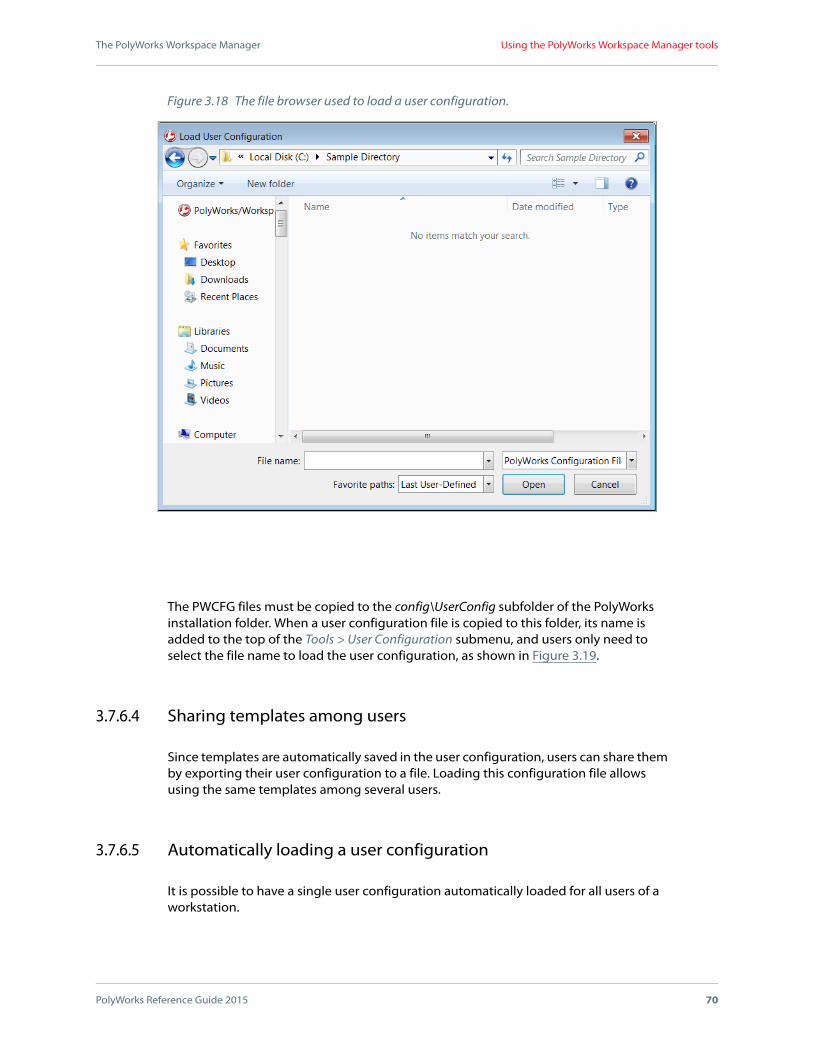
The PolyWorks Workspace Manager
PolyWorks Reference Guide 2015 70
Using the PolyWorks Workspace Manager tools
The PWCFG files must be copied to the config\UserConfig subfolder of the PolyWorks installation folder. When a user configuration file is copied to this folder, its name is added to the top of the Tools > User Configuration submenu, and users only need to select the file name to load the user configuration, as shown in Figure 3.19.
3.7.6.4 Sharing templates among users
Since templates are automatically saved in the user configuration, users can share them by exporting their user configuration to a file. Loading this configuration file allows using the same templates among several users.
3.7.6.5 Automatically loading a user configuration
It is possible to have a single user configuration automatically loaded for all users of a workstation.
Figure 3.18 The file browser used to load a user configuration.

The PolyWorks Workspace Manager
PolyWorks Reference Guide 2015 71
Using the PolyWorks Workspace Manager tools
Administrators can copy a single PWCFG file to the config\UserConfig\autoload subfolder of the PolyWorks installation folder. That user configuration is automatically loaded on launching PolyWorks, without any user intervention being necessary.
At every subsequent launch, if PolyWorks detects that the PWCFG file has changed, or that a new file has been put in the Autoload folder, the user configuration is loaded again, overwriting the current user configuration. In this case, a backup is first made of the current user configuration.
Note that the user configuration of the Autoload folder is also added to the Tools > User Configuration submenu.
3.7.6.6 Restoring the PolyWorks default configuration
The default PolyWorks configuration uses the Manufacturing application mode, which consists of the Manufacturing system visual layout and a set of configuration settings (e.g., default values including methods and submethods); this corresponds to the first installation of PolyWorks. Application modes are explained in Section 3.7.8.1 General options, and visual layouts are presented in Chapter 4 Customizing the Graphical User Interface.
To restore the PolyWorks default configuration, choose the Tools > User Configuration > Restore PolyWorks Defaults command. If a module remained open, or if an untitled workspace or macro script is modified, an error message is displayed; close the module or save the workspace or script to continue. The system makes a backup of the current user configuration and then performs the operation and restarts the PolyWorks Workspace Manager. The default configuration is restored and the previously opened workspaces are opened again.
Figure 3.19 An example of the Tools > User Configuration submenu of the Workspace Manager showing two standard user configurations.

The PolyWorks Workspace Manager
PolyWorks Reference Guide 2015 72
Using the PolyWorks Workspace Manager tools
If the operation does not correspond to the expected results, it is possible to return to the previous configuration. For more information, see Section 3.7.6.1 Loading a user configuration.
3.7.6.7 Restoring backups
Three operations allow generating a backup of the current user configuration: loading a user configuration, loading a backup configuration, and restoring the PolyWorks default configuration. Up to ten backups are listed by date and time for each user configuration on Tools > User Configuration > Restore Backups submenu.
To restore a backup, choose it from the Tools > User Configuration > Restore Backups submenu.
Depending on the type of operation that was performed, backups are displayed differently in the list:
When loading a user configuration, backups are displayed as follows:
[date] - [time] - Before loading [file name]
When loading a backup, backups are displayed as follows:
[date] - [time] - Before loading backup of [backup date] - [backup time]
When restoring PolyWorks defaults, backups are displayed as follows:
[date] - [time] - Before restoring PolyWorks defaults
Also, a backup is automatically generated when opening the PolyWorks Workspace manager after having upgraded or downgraded to a different version of PolyWorks. For more information, see Section 3.7.6.8 Determining the user configuration when using a previous version of PolyWorks.
3.7.6.8 Determining the user configuration when using a previous version of PolyWorks
A current user configuration may be incompatible with previous versions of PolyWorks (i.e., major versions and intermediate releases). To prevent incompatibility issues, the following strategy is used when opening the PolyWorks Workspace Manager after having installed a previous version of PolyWorks:
If an existing user configuration corresponds to the previous version of PolyWorks, it is used.
If no user configuration corresponds to the previous version of PolyWorks, the default user configuration is restored.

The PolyWorks Workspace Manager
PolyWorks Reference Guide 2015 73
Using the PolyWorks Workspace Manager tools
Note that when opening the PolyWorks Workspace Manager after having installed a different version of PolyWorks, a backup of the previous user configuration is saved as a PWCFG file in the following folder:
[user configuration folder]\.innovmetric.[version]\config\backup\intermediate_release\ ,
This backup can be restored in a more recent version of PolyWorks. For more information, see Section 3.7.6.7 Restoring backups.
3.7.6.9 Elements of a user configuration
PolyWorks modules can be customized by modifying global options, defining annotation, control, and table templates, as well as visual layouts, color scales, and more. These customizations are referred to as the user configuration.
A user configuration includes the following elements:
All module options (available through the Tools > Options command). At any time, options can be transferred to the user configuration using a module’s Tools > Save User Configuration command.
Templates (table, annotation, control, tolerance, color scale, and text file). On creation, new templates are saved in the user configuration. User templates are identified by the icon preceding their name.
Visual layouts and macro scripts saved explicitly to the user configuration.
User-defined probes and reflectors, as well as user-defined profiles for line scanning plug-ins.
The user configuration consists of a folder containing all of these elements, organized by module. It is located on disk in the user account. The current user configuration is loaded on launching the Workspace Manager or a PolyWorks module.
3.7.7 Using visual layouts
The Tools >Visual Layout submenu offers the commands that follow. A brief description is provided for each command. A reference is also made to the section of the PolyWorks Reference Guide chapter that explains the functionality in detail.
The first commands allow specifying a system visual layout.
Manufacturing
Loads the Manufacturing system visual layout.
Surveying
Loads the Surveying system visual layout.

The PolyWorks Workspace Manager
PolyWorks Reference Guide 2015 74
Using the PolyWorks Workspace Manager tools
All Applications
Loads the All Applications system visual layout.
Note that new system visual layouts can be added by either saving or copying a visual layout to the visual_layout subfolder of the PolyWorks installation folder. This customized system visual layout then appears at the end of the system visual layouts list available under the Tools > Visual Layout submenu of the corresponding module.
The submenu also offers the following commands that allow performing operations on existing visual layouts:
Load
Loads a visual layout from an external file. For more information, see Section 4.2.4 Loading a visual layout.
Save
Saves a visual layout to an external file. For more information, see Section 4.2.3 Exporting a visual layout.
Backups
Loads a backed up visual layout file from a list of layout files. A layout file is identified by the date and hour it was backed up. For more information, see Section 4.2.1 Introducing the visual layout mechanism.
Import Macro Scripts from Layout
Creates a new toolbar with the macro scripts imported from a visual layout file. For more information, see Section 4.2.6 Importing macro scripts from visual layouts.
Customize
Starts the visual layout customization mode.
Customizing toolbars, menu bars, menu item shortcuts, options, and macro scripts is done using a module’s Customize Visual Layout dialog box, shown in. For complete information, see Section 4.3 Customizing an application’s visual layout.
The Customize Visual Layout dialog box offers the following tabs:
ToolbarsA tab that offers the list of toolbars available in the application. It allows showing and hiding toolbars, as well as creating, renaming, and deleting custom toolbars. It also offers the Reset button to reset the selected toolbars to their initial state.
CommandsA tab that lists all the of the commands in the application. Choose a main menu command or a toolbar in the Categories list box, and all of the available commands for the selected category appear in the Commands list box. To add a command to a toolbar or menu, select it in the Commands list box and drag in on the desired toolbar or menu. See Section 4.3.2.9 Adding toolbar buttons and menu commands for more information.

The PolyWorks Workspace Manager
PolyWorks Reference Guide 2015 75
Using the PolyWorks Workspace Manager tools
KeyboardA tab that allows assigning a keyboard shortcut to any command available in the application. See Section 4.3.2.13 Creating keyboard shortcuts for more information.
OptionsA tab that offers allows locking the docking windows, setting the size of toolbar buttons, and defining the screen tips and animation type. See Section 4.3.2.14 Customizing options for more information.
Macro ScriptsA tab that allows managing the macro scripts in the current visual layout and assigning them to a toolbar or menu. See Section 4.3.2.15 Managing macro scripts for more information.
For complete information on customizing visual layouts, choose the Interface Customization command on the Help menu of the PolyWorks Workspace Manager. The PolyWorks Reference Guide opens in PDF format to the chapter on visual layout customization.
3.7.8 Setting PolyWorks options
PolyWorks options are located in the PolyWorks Workspace Manager Options dialog box. It is accessed by choosing the Tools > Options command, and shown in Figure 3.20.
The options allow configuring the PolyWorks software suite, and include specifying:
An application mode which impacts default values and menu offerings.
The desired language and font.
The default directories.
The plug-ins to load at startup.
The translators to use for the export of polygonal models, and so on.
Any changes made to options, and applied by pressing the dialog box’s OK or Apply buttons, are automatically saved to the user configuration. The options are all documented in this chapter. Note that each module (i.e., IMAlign, IMEdit, IMInspect, IMSurvey) and PolyWorks|Viewer offer their own options dialog box that contains options specific to each module.
Note that information on how to use the options dialog box (i.e., apply changes, interpret error messages) is provided in Section 5.2 Using a module’s Options dialog box of the PolyWorks Reference Guide.

The PolyWorks Workspace Manager
PolyWorks Reference Guide 2015 76
Using the PolyWorks Workspace Manager tools
3.7.8.1 General options
The General page of the PolyWorks Workspace Manager Options dialog box, shown in Figure 3.20, allows setting general options.
Application modeA list box that offers application modes to meet the needs of specific groups of users of the IMAlign, the IMEdit, the IMInspect, and the IMSurvey modules. An application mode consists of certain configuration settings (e.g., default values), as well as a system visual layout that controls the content and layout of the graphical user interface. Choose from:
Manufacturing – Provides the PolyWorks functionalities required by users in the manufacturing sector for each module. The Manufacturing system visual layout is used.
Sheet Metal – Provides the PolyWorks functionalities required by users in the manufacturing sector for each module. In addition, certain default values relevant to the inspection of sheet metal are applied for the IMInspect module. The Manufacturing system visual layout is used.
Surveying – Provides the PolyWorks functionalities required by users in the surveying sector for each module. The Surveying system visual layout is used.
Figure 3.20 The General page of the PolyWorks Workspace Manager Options dialog box.
The PolyWorks Workspace Manager
PolyWorks Reference Guide 2015 77
Using the PolyWorks Workspace Manager tools
All Applications – Provides all of the functionalities available for each module. The All Applications system visual layout is used.
All PolyWorks applications must be closed before choosing an application mode. Once specified, it will provide the visual layout of the PolyWorks Workspace Manager and the IMAlign, IMEdit, IMInspect, and IMSurvey modules at their next start-up, as well as any configuration settings that may apply; the same is true for PolyWorks|Viewer. By default, the Manufacturing application mode is specified.
Note that when the Manufacturing application mode is specified, items related to surveying are removed from the PolyWorks Workspace Manager (i.e., button on the Modules toolbar, branch in the Workspace tree view). However, if a workspace containing an IMSurvey project is opened, the related branch is displayed in the tree view.
For more information concerning visual layouts, see Chapter 4 Customizing the Graphical User Interface.
Default length unitsA list box that specifies the units of length by default for the PolyWorks modules. Choose from: Microns, Millimeters, Centimeters, Meters, Inches, Feet, and US Survey Feet. The default value is Millimeters.
By default, the Length option of modules will be set to this value. If the user changes the setting for the Length option when using an instance of a module, for example IMEdit, future IMEdit projects will use the new units of length specification.
The Browsers section offers an option for file and folder browsers:
Working folderA check box that enables specifying a folder to which a browser initially refers when it is displayed. When the check box is selected, a path may be entered manually in the adjacent text box, or entered interactively by pressing the adjacent browse button and specifying a path. When the check box is cleared, the working folder is the last folder used. The check box is cleared by default.
The Default folders section allows specifying three default folders:
WorkspaceA text box that allows specifying the default folder for workspaces. An adjacent Browse button is also offered to specify the path interactively. On pressing the button a folder browser is displayed – specify a folder and press the Select Folder button. The default value is ...\My Documents\PolyWorks.
User configurationA text box that allows specifying the default parent folder of the user configuration subfolder. An adjacent Browse button is also offered to specify the path interactively. On pressing the button a folder browser is displayed – specify a folder and press the Select Folder button.

The PolyWorks Workspace Manager
PolyWorks Reference Guide 2015 78
Using the PolyWorks Workspace Manager tools
Temporary filesA text box that allows specifying the default folder to use for temporary files. An adjacent Browse button is also offered to specify the path interactively. On pressing the button a folder browser is displayed – specify a folder and press the Select Folder button.
3.7.8.2 Display options
The Display page of the PolyWorks Workspace Manager Options dialog box, shown in Figure 3.21, allows setting options for language and font preferences, dialog boxes, message window scaling, and tree view branches.
LanguageA list box that sets the language for the user interface. Choose from: Chinese_big5, Chinese_simplified, Czech, English, French, German, Italian, Japanese, Portuguese, Russian, and Spanish. The default language is English.
The Fonts section offers three items.
Character setA list box that specifies the set of characters that can be entered in text boxes. Unicode is fully supported. Object names, text annotations, table titles, and so on can be written in any language, as long as the appropriate character set is chosen for the display. The default value is Western Alphabet.
Figure 3.21 The Display page.

The PolyWorks Workspace Manager
PolyWorks Reference Guide 2015 79
Using the PolyWorks Workspace Manager tools
Dialog boxesA list box that specifies a font for the dialog boxes. Only fonts that support the chosen character set are displayed in the list box. The default value is Microsoft Sans Serif.
3D SceneA list box that specifies the font used to display text in the 3D Scene pane. Only fonts that support the chosen character set are displayed in the list box. The default value is Microsoft Sans Serif.
Modules that are opened will use the specified language and fonts. To apply these settings to the PolyWorks Workspace Manager, it is necessary to exit the PolyWorks Workspace Manager and then start it again.
The Dialog boxes section offers the following option:
Show the Open or Create Workspace dialog box at startupA check box that enables displaying the Open or Create Workspace dialog box at startup. The check box is cleared by default. For more information, see Section 3.1.3 The Open or Create Workspace dialog box.
The Message windows section offers the following options:
Window scaling (%)A text box that specifies a scaling factor to apply to message windows, as well as to the input dialog boxes available from the Macro Script Control Language. Valid values include integer values that range from 100 to 500 inclusively. The default value is 100%, which corresponds to the original size. Scaling message windows may be useful for applications that require seeing the windows from a distance and that allow responding by pressing buttons from a distance.
Restore Hidden MessagesA button that restores the display of those message windows that have a Never ask this question again check box that has been selected, and those dialog boxes that have a Never show this dialog box again check box that has been selected. This button is only available once such a check box has been selected, and it becomes unavailable immediately after it has been pressed.
The Tree view section offers the following options:
Show empty branchesA check box that enables displaying the empty branches in the tree view. By default, the check box is cleared.
3.7.8.3 Default name options
The Default Names page of the PolyWorks Workspace Manager Options dialog box, shown in Figure 3.22, allows specifying new default names for object types used to save

The PolyWorks Workspace Manager
PolyWorks Reference Guide 2015 80
Using the PolyWorks Workspace Manager tools
workspaces and projects, as well as polygonal model files produced by the IMMerge and IMCompress modules.
The page offers a list with the Object Type and Default Name columns. To edit a default name in the list, click it and enter a new name. Press the ESC key to undo the current editing. The list may feature a scroll bar to navigate the list.
3.7.8.4 Polygonal model options
The Polygonal Models page of the PolyWorks Workspace Manager Options dialog box, shown in Figure 3.23, offers items to configure file format translators.
The Export section offers the following options:
DXF translatorA list box that specifies a translator to use to write output DXF files. Choose from DXF Polyface or DXF 3DFace. The default value is DXF Polyface.
IGES translatorA list box that specifies a translator to use to write output IGES files. Choose from IGES 128 or IGES 108. The default value is IGES 128.
STL translatorA list box that specifies a translator to use to write output STL files. Choose from STL Binary or STL ASCII formats. The default value is STL Binary.
VRML translatorA list box that specifies a translator to use to write output VRML files. Choose from VRML 2 or VRML 1 formats. The default value is VRML 2.
Figure 3.22 The Default Names page.

The PolyWorks Workspace Manager
PolyWorks Reference Guide 2015 81
Using the PolyWorks Workspace Manager tools
3.7.8.5 Talisman options
The Talisman page of the PolyWorks Workspace Manager Options dialog box, shown in Figure 3.24, allows setting options for PolyWorks|Talisman™. Talisman is a remote control application developed to allow controlling a probing/scanning session using a mobile device. See the Talisman document and the Talisman Network Security and Setup Guide, available under the Help menu of the PolyWorks Workspace Manager, for more information on Talisman.
The Talisman page offers the following options:
PolyWorks server for TalismanA check box that enables the PolyWorks server for Talisman functionality for the IMInspect module or the IMAlign module. By default, the check box is cleared, which means that the PolyWorks server for Talisman functionality is disabled. Note that any change made to this option is automatically applied to the modules, including any open instances of these modules.
When the check box is selected, it makes available the following items:
Custom network settingsA check box that allows specifying both the server static port and server dynamic port numbers used to find an available port when communicating between the PolyWorks server for Talisman (IMInspect
Figure 3.23 The Polygonal Models page.
Figure 3.24 The Talisman page.

The PolyWorks Workspace Manager
PolyWorks Reference Guide 2015 82
Using the PolyWorks Workspace Manager tools
or IMAlign) and the client (mobile devices). By default, the check box is cleared, which means that the static and dynamic ports are automatically determined by the server. When the check box is selected, the following items are offered:
Server static portA text box that allows specifying the required static port number. The server static port is a TCP port used to connect the client to the PolyWorks server for Talisman. Enter the port number as described in the following table. Valid port numbers are 0 and integers between 1025 and 65535 inclusively. The default value is 28081.
Server dynamic portsA text box that allows specifying the required dynamic port numbers. A dynamic port is a TCP port used to connect the client to a project. Dynamic ports are communicated to the client through the static port. Enter the port numbers as described in the following table. Valid port numbers are 0 and integers between 1025 and 65535 inclusively. The default value is 1025-65535.
Zero means that the port number is automatically determined by the server.
Note that the number of concurrent PolyWorks servers for Talisman enabled on the same computer is limited by the number of allowed ports.
Note that on pressing the Apply button and the option is selected, the Bonjour networking technology, a trademark of Apple Inc., is automatically installed if necessary.
3.7.8.6 Plug-in options
The Plug-ins page of the PolyWorks Workspace Manager Options dialog box, shown in Figure 3.25, allows determining what plug-ins will be loaded at startup for the modules that support plug-ins. By default, the Load at startup check boxes are selected. Note that changing the status of the Load at startup check boxes does not affect the open
To specify... Values
A minimum port number only (e.g., 3000 and above)
3000-
A maximum port number only (e.g., 4000 and below)
-4000
A range of ports (e.g., between 3000 and 4000) 3000-4000
A single port number (e.g., 2000) 2000

The PolyWorks Workspace Manager
PolyWorks Reference Guide 2015 83
Using the PolyWorks Workspace Manager tools
modules; for those modules, plug-ins are not loaded or removed. The status of the plug-ins is automatically written to the user configuration, and is used at the next module startup.
When using PolyWorks for the first time, and if it was installed with plug-ins, a message window proposes to configure the plug-ins to load. On pressing the OK button, this page of the PolyWorks Workspace Manager Options dialog box is displayed to do the configuration. Select the check boxes under the Load at startup column for the desired plug-ins. Press the Apply button or the OK button to transfer the specifications to the application. If the Cancel button was pressed in the message window, all of the check boxes are silently selected; no dialog box is displayed.
When using PolyWorks and new plug-ins have been installed, the same process as the one that precedes is repeated. The only difference is that the new plug-ins are displayed in bold on the Plug-ins page in order to be easy to identify.
Figure 3.25 The Plug-ins page in the 64-bit version of PolyWorks.

The PolyWorks Workspace Manager
PolyWorks Reference Guide 2015 84
Getting help
3.8 Getting help
The Help menu offers access to documentation in PDF format as well as information about your version of PolyWorks.
3.8.1 Accessing the Essentials
The Essentials guides are intended to be a companion for new users post-training and throughout the first year of using PolyWorks.
The PolyWorks|Inspector Essentials, for both the Premium and Probing packages, and the PolyWorks|Modeler Essentials are offered. They are presented following a workflow and tool-based approach and, in most cases, describe only the basic parameters.
3.8.2 Accessing the reference documentation
The Help > Reference Guides menu offers commands that provide access to the InnovMetric Software manuals related to PolyWorks. These manuals consist of Adobe PDF files which require that Adobe Reader be installed on your system:
PolyWorks
Loads the PolyWorks Reference Guide into Adobe Reader. This is the document that the PolyWorks Workspace Manager dialog boxes link to when the ? symbol on their title bar is clicked.
Workspace Manager
Loads the PolyWorks Reference Guide into Adobe Reader and opens it to the chapter that describes the PolyWorks Workspace Manager.
License Keys
Loads the PolyWorks Reference Guide into Adobe Reader and opens it to the section that describes how to install and manage node-locked and floating license keys.
IMAlign
Loads the IMAlign Reference Guide into Adobe Reader. This is the document that the IMAlign dialog boxes link to when the ? symbol on their title bar is clicked.
IMCompress
Loads the IMCompress Reference Guide into Adobe Reader. IMCompress is a polygon reduction tool.
IMEdit
Loads the IMEdit Reference Guide into Adobe Reader. This is the document that the IMEdit dialog boxes link to when the ? symbol on their title bar is clicked.

The PolyWorks Workspace Manager
PolyWorks Reference Guide 2015 85
Getting help
IMInspect
Loads the IMInspect Reference Guide into Adobe Reader. It contains detailed information. This is the document that the IMInspect interfaces link to when the ? symbol on their title bar is clicked.
IMMerge
Loads the IMMerge Reference Guide into Adobe Reader. IMMerge is a tool that merges 3D images from an IMAlign project into a unified polygonal mesh.
IMSurvey
Loads the IMSurvey Reference Guide into Adobe Reader. It contains detailed information. This is the document that the IMSurvey dialog boxes link to when the ? symbol on their title bar is clicked.
IMTexture
Loads the IMTexture Reference Guide into Adobe Reader. IMTexture is a tool for generating texture maps and works in conjunction with IMCompress.
PolyWorks|Viewer
Loads the PolyWorks|Viewer Reference Guide into Adobe Reader. This is the document that the PolyWorks|Viewer dialog boxes link to when the ? symbol on their title bar is clicked.
PolyWorks|Talisman
The PolyWorks|Talisman submenu offers commands that provide access to the User Guides, for both Android and Apple mobile devices, and the Network Security and Setup Guide.
Android Mobile Device User Guide
Loads the Android Mobile Device User Guide into Adobe Reader.
Apple Mobile Device User Guide
Loads the Apple Mobile Device User Guide into Adobe Reader.
Network Security and Setup Guide
Loads the Network Security and Setup Guide into Adobe Reader.
Commands
Loads the Command Reference Guide in a Web browser. This document presents the application commands that are specific to the module as well as the elements of the Macro Script Command Language.
Macro Scripts
Loads the Macro Scripting Reference Guide into Adobe Reader. This document explains how to create basic macros by saving and editing macros using the Macro Script Editor. It also describes the Macro Script Command Language that enables users to add programming functionalities to macros.

The PolyWorks Workspace Manager
PolyWorks Reference Guide 2015 86
Getting help
PolyWorks SDK
Loads the PolyWorks SDK Reference Guide into Adobe Reader. This document provides information concerning plug-ins and COM architecture. Many samples are provided.
Translators
Loads the Translators Reference Guide into Adobe Reader. This manual provides additional information on the file format translators offered by InnovMetric Software. The polygonal format conversion tool, IMConvert, is also presented.
Interface Customization
Loads the PolyWorks Reference Guide into Adobe Reader and opens it at the chapter that describes interface customization.
3.8.2.1 Accessing the reference documentation from dialog boxes
On clicking the question mark on the title bar of an PolyWorks dialog box, the PDF version of the appropriate reference guide, or other appropriate document, opens to the related section. Pressing the F1 key performs the same operation with respect to a dialog box. When in an interactive mode, pressing the F1 key displays the related instruction wizard.
3.8.2.2 Accessing documentation for plug-ins
To access a plug-in document, look under the Help > Reference Guides > Plug-ins submenu of the PolyWorks Workspace Manager, or the Help > Reference Guides submenu of the related module.
3.8.2.3 Topics not yet documented
Topics not yet documented will be available shortly in the documentation of upcoming major and intermediate releases of PolyWorks 2015.
Summary information on this topic may be found in the “Summary of New Tools in PolyWorks” document, available under the Help menu of the PolyWorks Workspace Manager, or in a learning video.
For immediate information on this subject, contact your technical support personnel.
3.8.3 What’s new in PolyWorks
The Help > What’s New submenu of the PolyWorks module offers documents that summarily explain what is new in the major and intermediate releases of PolyWorks:

The PolyWorks Workspace Manager
PolyWorks Reference Guide 2015 87
Getting help
The “Summary of New Tools in PolyWorks” document, available by choosing the module name, is useful for users who have worked with previous versions of this module. It contains a summary of what is new in the latest major release of PolyWorks.
A summary of the new tools in all modules is available under the Help > What’s New submenu of the PolyWorks Workspace Manager.
The “Intermediate Release Notes” document provides the list of fixes and enhancements in each intermediate release of PolyWorks since the last major release of PolyWorks. It is also available under the Help > What’s New submenu of the PolyWorks Workspace Manager.
3.8.4 The Support Assistant
When a module or an application ends unexpectedly, crash dump files are created that may help diagnose the source of the problem. These files can be packed in a .pwsa file using the Support Assistant tool. For technical support, send the .pwsa file directly to your PolyWorks provider, or to the InnovMetric Software technical support team by e-mail at [email protected].
The Support Assistant tool can be accessed by pressing the Yes button in the message window displayed when a crash occurs. If the No button is pressed, the Support Assistant tool can always be accessed at a later time from the Help menu of the PolyWorks Workspace Manager, or the Help menu of PolyWorks|Viewer, as well as any of the following modules: IMAlign, IMEdit, IMInspect, and IMSurvey.
When the Support Assistant tool is invoked, a file browser is displayed to specify a file name and a location on disk, as shown in Figure 3.26. A detailed report providing information on your system and on all unreported crashes is then generated in a .pwsa file. Crash dump files are erased as soon as they are used by a .pwsa file to generate a
Figure 3.26 The browser for the Support Assistant.

The PolyWorks Workspace Manager
PolyWorks Reference Guide 2015 88
Displaying the .pif extension in file browsers
report. By default, the name of the .pwsa file is PolyWorks Support Assistant YYYY-MM-DD.pwsa.
The Support Assistant can also be invoked by way of a command line, executed from the bin subfolder of the PolyWorks installation folder. A general call to the Support Assistant has the following format:
support_assistant [system_report_filename] [-p] [-k]
The system_report_filename parameter specifies the file name and location for the created report.
The -p parameter specifies that the system report should display in a Notepad application.
The -k parameter specifies keeping the crash dump files so that they can be used in future .pwsa files.
These three parameters are optional. If they are not specified, the report appears directly in the Command Prompt window.
3.8.5 About PolyWorks
The Help > About PolyWorks command provides copyright and version information for your version of PolyWorks.
On choosing the command, a splash screen is displayed that displays the software’s version and build number. The build number helps InnovMetric Software’s development team track the precise source code used to compile the application.
3.9 Displaying the .pif extension in file browsers
This section concerns using the InnovMetric Software PIF format – PIF files describe 3D digitizer data and may have the extension .pif or .pf.
In Windows, PIF is the acronym for program information file. A PIF file provides information to Windows about how best to run MS-DOS applications. Windows PIF files have the extension .pif. Because the pif extension is interpreted by Windows as a Windows PIF file, the pif extension of the InnovMetric Software PIF files is not displayed in file browsers.
Windows PIF files are only used for backward compatibility with MS-DOS applications. If you are not using MS-DOS applications and want to display the full names of InnovMetric Software PIF files in file browsers, you may modify the Windows configuration to delete the pif extension from the list of recognized extensions.
To reconfigure Windows to display the pif extension, follow this procedure to modify the registry:

The PolyWorks Workspace Manager
PolyWorks Reference Guide 2015 89
Running macros on opening and on closing a workspace
WARNING: Only perform the operations described below.
1. Log on as the Administrator user.
2. In a Command window, type
regedit
3. Double-click HKEY_CLASSES_ROOT.
4. Choose the pif extension.
5. Right-click and click Delete on the shortcut menu.
6. Exit the registry window.
3.10 Running macros on opening and on closing a workspace
The PolyWorks Workspace Manager allows creating macros using the Macro Script Editor and enhancing them using the Macro Script Command Language. For more information, see the Macro Scripting in PolyWorks document.
3.10.1 Displaying the Macro Script Editor
The Tools > Macro Scripts > Macro Script Editor command enables the display of the Macro Script Editor pane.
The Macro Script Editor pane, shown in Figure 3.27, can be used to record each of your actions in the software as commands and save them as a macro script to a Unicode text file. A macro script can then be edited, enhanced by a simple but powerful programming language, and assigned to toolbar buttons for execution. Refer to the Macro Scripting Reference Guide for complete documentation on the Macro Script Editor and the macro script programming language.
Note that this pane cannot be used when certain operation modes are active.
3.10.2 Running a macro script automatically on opening a workspace
A workspace, on opening, may run a special macro script. This can be useful to automatically launch certain PolyWorks modules or opening specific PolyWorks projects. The macro script must be saved in the Macro\PolyWorks subfolder of the workspace’s _Files folder (see Section 3.1.2 Introducing the workspace format), and its name must be Autorun.WorkspaceOpen.

The PolyWorks Workspace Manager
PolyWorks Reference Guide 2015 90
Running macros on opening and on closing a workspace
An example of such a macro script is shown in Figure 3.28. It first queries the user to continue. If the user answers Yes, the macro script continues with commands that tell the PolyWorks Workspace Manager to open modules using specific objects in the active workspace:
Open the “Curve Network Analysis” project in IMEdit.
Open the “IMBase” project in IMAlign.
Open the “IMBlock” project in IMInspect.
Open the “IMInspect Project sm” project in Viewer.
Refer to the Macro Script Reference Guide for complete documentation on the Macro Script Editor and the macro script programming language.
3.10.3 Scripting a complete workflow
Commands are available in the PolyWorks Workspace Manager’s Macro Script Editor that allow opening any desired modules, and performing commands in those modules and/or executing scripts written for those modules, in order to realize an entire workflow. For an example that uses four modules, see Section 4.5 Creating a multiapplication script of the Macro Script Reference Guide.
Figure 3.27 The Macro Script Editor allows recording, editing, enhancing, debugging, and running macro scripts.

The PolyWorks Workspace Manager
PolyWorks Reference Guide 2015 91
Running macros on opening and on closing a workspace
3.10.4 Running a macro script automatically on closing a workspace
A workspace, on closing, may run a special macro script. This can be useful for saving shared variables. The macro script must be saved in the PolyWorks subfolder of the Macro folder of the workspace’s _Files folder (see Section 3.1.2 Introducing the workspace format), and its name must be Autorun.WorkspaceClose.
Figure 3.28 A sample Autorun.WorkspaceOpen macro script.

4
PolyWorks Reference Guide 2015 92
Customizing the Graphical User Interface
The PolyWorks graphical user interface offers full customization capabilities throughout all applications, except Viewer, by way of visual layouts. This chapter provides detailed information regarding visual layouts and how to customize them.

Customizing the Graphical User Interface
PolyWorks Reference Guide 2015 93
Introduction
4.1 Introduction
Visual layouts allow full customization of the graphical user interface. Visual layouts can be designed for specific departments and applications, which may result in simplified learning curves and increased user performance and satisfaction. Or, individual users may customize PolyWorks to their preferred way of using the software. Visual layouts allow the user to:
Create new task-specific toolbars.
Add macros to a visual layout and assign them to a toolbar or a menu bar.
Strip menus of unused items.
Assign familiar shortcuts to specific menu items.
Dock windows and display only required panes.
Specify options such as locking docking windows, and using large icons or toolbar animation (available in Viewer).
PolyWorks comes packaged with three system visual layouts, which are part of the application mode specified in the PolyWorks Workspace Manager. They serve as an initial configuration for the PolyWorks Workspace Manager as well as the IMAlign, the IMEdit, the IMInspect, and the IMSurvey modules, and PolyWorks|Viewer.
Visual layouts are not stored within a project. On closing a project, the current visual layout is automatically saved to an external file in the user configuration folder. The last saved visual layout is automatically loaded the next time the project is opened. Note that visual layouts can be shared by manually saving them to external files (*.vlt) which can then be loaded by other users working with the same module (e.g., IMEdit). See Section 4.2.3 Exporting a visual layout for more information on saving visual layouts.
4.2 Using visual layouts
Visual layouts control the content and layout of the graphical user interface. A visual layout is composed of several elements, including the menu bar, toolbars, and docking panes (see Figure 4.1 for an example). It contains the visibility status, location, and preferences of each individual pane, toolbar, menu, and macro script.
PolyWorks provides system visual layouts that are part of the chosen application mode, specified with all modules closed, on the General page of the PolyWorks Workspace Manager Options dialog box. The system visual layout that is part of the application mode is then applied to the PolyWorks Workspace Manager, and the IMAlign, IMEdit, IMInspect, IMSurvey modules, as well as PolyWorks|Viewer. Customized layouts can be created and applied to a specific application.

Customizing the Graphical User Interface
PolyWorks Reference Guide 2015 94
Using visual layouts
The Tools > Visual Layout submenu of modules and the PolyWorks Workspace Manager contains commands for loading and saving visual layouts, and importing macro scripts from layouts.
4.2.1 Introducing the visual layout mechanism
First, the user chooses an application mode in the Workspace Manager; each application mode applies a specific configuration and a specific system visual layout. All modules must be closed to change the application mode. The Application mode list box is located on the General page of the PolyWorks Workspace Manager Options dialog box (see Section 3.7.8.1 General options).
Figure 4.1 The elements of an application’s visual layout include docking panes, toolbars, and menu commands. Elements are shown here for the IMInspect module.
Standardtoolbar
3D Scenetoolbar
Docking panes
Main Objects toolbar
Main Menubar
active pane
Selectiontoolbar
Device Positiontoolbar
Probingtoolbar

Customizing the Graphical User Interface
PolyWorks Reference Guide 2015 95
Using visual layouts
This layout will be used by the IMAlign, IMEdit, IMInspect, and IMSurvey modules the first time they start. This is useful for configuring the software for use, for example, by a user in manufacturing, or someone in surveying.
The user may then configure the module’s visual layout - called the current visual layout - during that session in the module. On closing the module, the current visual layout is automatically saved to the user configuration as a backup. At any time during a session, the user can save the current visual layout to an external visual layout (.vlt) file, which can be used later, be shared with colleagues, or become a de facto visual layout for that module.
On starting the same module again, the most recent backup of the visual layout is loaded. Note that if a new system visual layout has been defined in the PolyWorks Workspace Manager, the module will start using that visual layout. The user may choose to load an external .vlt file.
See Figure 4.2 for an illustration of the visual layout mechanism, using the IMAlign module as an example.
The mechanism of visual layouts in the PolyWorks Workspace Manager is the same. The Workspace Manager starts out in Manufacturing application mode, and uses the same auto-save and auto-load, and save-to-file and load-from-file operations for its visual layout.
Note that in the subsections that follow, the term module regroups the IMAlign, the IMEdit, the IMInspect, and the IMSurvey modules, while the term application includes the modules and the PolyWorks Workspace Manager as well.
4.2.2 Setting the application mode in the PolyWorks Workspace Manager
The PolyWorks Workspace Manager offers three system visual layouts to meet the needs of specific groups of users of the IMAlign, the IMEdit, the IMInspect, and the IMSurvey modules. For more information, see Section 3.7.8.1 General options.
4.2.3 Exporting a visual layout
It is possible to export an application’s current visual layout, which includes the visibility status, location, and preferences of each individual pane, toolbar, menu, and macro. To export a visual layout, choose the Tools > Visual Layout > Export command. The file browser shown in Figure 4.3 is displayed. Specify a file name with the .vlt extension and a location. The browser’s Favorite paths list box offers predefined locations: Workspace, User Configuration, and Last User-Defined. Press the Save button to perform the operation.
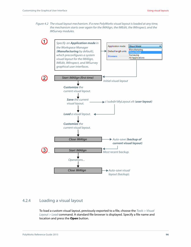
Customizing the Graphical User Interface
PolyWorks Reference Guide 2015 96
Using visual layouts
4.2.4 Loading a visual layout
To load a custom visual layout, previously exported to a file, choose the Tools > Visual Layout > Load command. A standard file browser is displayed. Specify a file name and location and press the Open button.
Start IMAlign (first time)
Figure 4.2 The visual layout mechanism. If a new PolyWorks visual layout is loaded at any time, the mechanism starts over again for the IMAlign, the IMEdit, the IMInspect, and the IMSurvey modules.
Specify an Application mode in the Workspace Manager (Manufacturing by default), which preconfigures a system visual layout for the IMAlign, IMEdit, IMInspect, and IMSurvey graphical user interfaces.
Customize the current visual layout.
Save the current visual layout.
Customize the current visual layout.
Close IMAlign
Start IMAlign
Close IMAlign
Load a visual layout.
Auto-save (backup of current visual layout)
Auto-save visual layout (backup).
c:\subdir\MyLayout.vlt (user layout)
Most recent backup.
Initial visual layout
Operations...
...

Customizing the Graphical User Interface
PolyWorks Reference Guide 2015 97
Using visual layouts
A visual layout loaded from a file is only applied to the application from which it was created. Once loaded, the visual layout automatically replaces the existing visual layout.
4.2.5 Opening a visual layout backup
When exiting an application, the current visual layout is automatically saved to the user configuration folder as a backup copy, which will be used the next time the application is launched. Up to eight visual layout backups are saved for each application. The naming scheme applied to each backup consists in the date and time at which it was created and the .vlt extension (e.g., yyyymmddhhmmss.vlt). These backups are listed by order of creation, starting with the most recent, under the Tools > Visual Layout > Restore Backups submenu of each application.
It is possible to open any of the eight visual layout backups by choosing it on the Tools > Visual Layout > Backups submenu. When a backup visual layout is opened, it automatically becomes the application’s current visual layout.
4.2.6 Importing macro scripts from visual layouts
Macro scripts may be created in an application’s Macro Script Editor and stored in the current visual layout. A macro script may also be imported from another visual layout. This is particularly useful in recuperating macro scripts from another visual layout without having to load it. An imported macro script is copied into the visual layout with no links to the source file – if the original macro script is modified, the one copied to the visual layout is not changed, and vice versa. A macro script in a visual layout may be dragged onto a toolbar or a menu bar.
To import macro scripts from other visual layouts into the current visual layout, use the following command on the Tools > Visual Layout submenu:
Figure 4.3 The file browser used to export a visual layout to disk.

Customizing the Graphical User Interface
PolyWorks Reference Guide 2015 98
Using visual layouts
Import Macro Scripts from Layout
Displays a file browser like the one shown in Figure 4.3 to specify the name and location of a visual layout file (.vlt). The Favorite paths list box allows visualizing the list of visual layouts for the application in the current Workspace, the User Configuration folder, or the System Configuration folder. Choose a visual layout file and press the Open button. All of the macro scripts will be imported into the current visual layout and assigned to a toolbar that is displayed.

Customizing the Graphical User Interface
PolyWorks Reference Guide 2015 99
Customizing an application’s visual layout
4.3 Customizing an application’s visual layout
The PolyWorks Workspace Manager, as well as IMAlign, IMEdit, IMInspect, and IMSurvey offer extensive customization capabilities. This includes setting the visibility status, size, position, and content of the visual layout’s docking panes, toolbars, and menus, as well as managing keyboard shortcuts, managing macro scripts contained in a visual layout, and specifying options related to display and locking docking windows.
The customization of a visual layout is performed within an application and is applied to that specific application only. The following subsections provide detailed information on the PolyWorks customization capabilities.
4.3.1 Customizing the docking panes
All PolyWorks applications with a GUI contain a number of docking panes, which can be customized in various ways, ensuring layout flexibility and optimization. The following table lists and describes the main panes available for each listed application. Other docking panes are only available within specific modes, and are described in their respective reference guides.
Pane DescriptionW
orks
pac
eM
anag
er
IMA
lign
IMEd
it
IMIn
spec
t
IMSu
rvey
Vie
wer
3D Scene
A pane that illustrates the 3D object rendering and manipulations. Note that the 3D Scene pane cannot be hidden.
Command History
A pane that echoes the commands given by way of menus and interfaces, and those executed by means of macro scripts. It also allows the user to give individual commands to try them out.
Dialog Zone
A pane that allows the user to control the display area of dialog boxes. It contains most dialog boxes that activate interactive modes.
GeometryControls
A pane that allows the user to specify dimensional and GD&T controls for features. This pane is in read-only mode in Viewer when viewing IMInspect projects. See the chapter Chapter 24. of the IMInspect Reference Guide for more information.

Customizing the Graphical User Interface
PolyWorks Reference Guide 2015 100
Customizing an application’s visual layout
The pane customization possibilities are described in the following subsections.
Histogram
A pane that shows histograms of image alignment errors following a best-fit iterative alignment operation (see the section Histogram pane of the IMAlign Reference Guide for more information).
Macro Script Editor
A pane that allows the user to record commands given by way of the graphical user interface and save them to a macro script. Macro Script Control Language commands can then be added to enhance the script. Scripting enables automating small and large tasks. See the section The Macro Script Editor pane of the Macro Scripting in PolyWorks document for more information.
Properties
A pane that displays creation and modification date information, a screen snapshot (for projects only), and notes for the selected object (see Section 3.1.4 Organization of the PolyWorks Workspace Manager interface for more information).
Report Editor
A pane that opens the Report Editor tool used to create, edit, and customize formatted reports (see the chapter Chapter 32. of the IMInspect Reference Guide for more information).
Tree ViewA pane that offers the application’s object tree view.
Workspaces
A pane that manages multiple workspaces and their content (see Section 3.1.4 Organization of the PolyWorks Workspace Manager interface for more information).
Pane Description
Wor
ksp
ace
Man
ager
IMA
lign
IMEd
it
IMIn
spec
t
IMSu
rvey
Vie
wer

Customizing the Graphical User Interface
PolyWorks Reference Guide 2015 101
Customizing an application’s visual layout
4.3.1.1 Opening and closing docking panes
The View menu offers a list of the main docking panes available for the current application. Note that the complete list can be accessed by right-clicking the title bar of an open pane, or by using a pane’s caption menu button on the title bar. To open a pane, choose the corresponding command in the list. An active pane is identified in the list by a checked command.
To close an active pane, choose the corresponding checked command in the list or press the closing button on the title bar. Note that when closing floating tabbed panes, all panes will be closed at once. When closing anchored tabbed panes, only the visible pane is closed (see Section 4.3.1.2 Changing the position of docking panes for more information on obtaining and manipulating tabbed panes).
4.3.1.2 Changing the position of docking panes
The location of a pane within the graphical user interface can be modified by dragging and docking the pane in the desired location, if the Lock window docking option is cleared (see Section 4.3.2.14 Customizing options). When dragging panes, note the following:
While dragging a pane, docking stickers will appear, guiding the docking process and visually displaying where the pane will be docked. Drag a pane on a docking sticker or anywhere on the screen. In both cases, a shaded area will appear indicating the location where the pane will be docked. Release the left mouse button to dock the pane. There are various possible docking locations for each pane:
Goal Instructions
To drag a pane Click the title bar and hold the mouse button.
To drag tabbed panes all at once.
Click the title bar of the top pane and hold the mouse button.
To drag one tabbed pane.
Click the pane’s tab and hold the mouse button.
Goal Instructions
To dock a pane at the top, at the bottom, to the right, or to the left of the entire docking zone.
Drag it on one of the four outer docking stickers, as shown in Figure 4.4 (a).
To dock a pane at the top, at the bottom, to the right, or to the left of another pane.
Drag it on one of the four inner docking stickers, as shown in Figure 4.4 (b).

Customizing the Graphical User Interface
PolyWorks Reference Guide 2015 102
Customizing an application’s visual layout
Note that if the pane’s new location is not satisfactory, double-click its title bar or its tab to switch between its previous location and its new location.
To dock a pane over another pane. Drag it on the center sticker, as shown in Figure 4.4 (c).
In this case, a tab is created for each pane at the bottom of the pane area.
To leave a pane floating. Release the left mouse button anywhere on the screen, but not over a sticker, as shown in Figure 4.4 (d).
Goal Instructions
Figure 4.4 The docking stickers used to docking a pane. The Tree View pane is being dragged (a) on an outer sticker, (b) on an inner sticker, (c) on the center sticker, and (d) in a floating location. In all cases, a shaded area indicates the pane’s new location.
(a) (b)
(c) (d)

Customizing the Graphical User Interface
PolyWorks Reference Guide 2015 103
Customizing an application’s visual layout
4.3.1.3 Hiding docking panes automatically
Panes can be automatically hidden by pinning them to the side of an application’s docking zone, if the Lock window docking option is disabled (see Section 4.3.2.14
Customizing options). To hide a visible pane, press the pin button on the pane’s title bar. The pane will automatically be tabbed along the border of the user interface. Its location is determined by the pane’s previous docking operation, with respect to the entire docking zone (outer docking stickers). For example:
A pane that was docked on the outer-left-side docking sticker will be pinned on the left border of the user interface.
A pane docked to the inner-right side docking sticker of another pane which was docked on the outer-left side docking sticker will be pinned on the left border of the user interface.
To view the contents of a pinned pane, place the pointer over its tab. The pane will appear. When removing the pointer from the pane area, it will return to it’s tabbed position. Press the pin button again to unpin a pane and return it to its previous docked position.
4.3.2 Customizing toolbars, menus, options, and macro scripts
Toolbars and menus provide quick access to the tools available within an application. They can be customized in various ways, ensuring layout flexibility and optimization.
The following sections will provide detailed information on customizing toolbars, menu bars, menu item shortcuts, options, and macro scripts contained within a visual layout.
4.3.2.1 Launching the customization mode
Customizing toolbars, menu bars, menu item shortcuts, options, and macro scripts is done using an application’s Customize Visual Layout dialog box, shown in Figure 4.5. It is accessed by choosing the Tools > Visual Layout > Customize command, which is located on the submenu, as well as the Customize command offered on shortcut menus that are displayed in the following ways:
Right-clicking in the toolbar zone.
Right-clicking any toolbar or the main menu bar.
Clicking anywhere on a docking pane’s title bar or clicking the title bar’s caption menu button .

Customizing the Graphical User Interface
PolyWorks Reference Guide 2015 104
Customizing an application’s visual layout
The Customize Visual Layout dialog box offers the following tabs:
ToolbarsA tab that offers the list of toolbars available in the application. It allows showing and hiding toolbars, as well as creating, renaming, and deleting custom toolbars. It also offers the Reset button to reset the selected toolbars to their initial state.
CommandsA tab that lists all the of the commands in the application. Choose a main menu command or a toolbar in the Categories list box, and all of the available commands for the selected category appear in the Commands list box. To add a command to a toolbar or menu, select it in the Commands list box and drag in on the desired toolbar or menu. See Section 4.3.2.9 Adding toolbar buttons and menu commands for more information.
KeyboardA tab that allows assigning a keyboard shortcut to any command available in the application. See Section 4.3.2.13 Creating keyboard shortcuts for more information.
OptionsA tab that offers allows locking the docking windows, setting the size of toolbar buttons, and defining the screen tips and animation type. See Section 4.3.2.14 Customizing options for more information.
Figure 4.5 The Customize Visual Layout dialog box.

Customizing the Graphical User Interface
PolyWorks Reference Guide 2015 105
Customizing an application’s visual layout
Macro ScriptsA tab that allows managing the macro scripts in the current visual layout and assigning them to a toolbar or menu. See Section 4.3.2.15 Managing macro scripts for more information.
The Customize Visual Layout dialog box must be activated for manual customization operations (i.e., adding, deleting, and repositioning items on a toolbar, on a menu bar, or on a menu) to be made available. Note that once the dialog box is activated, each toolbar button or menu command also has a shortcut menu available through a right-click, offering other customization options.
Press the Close button to dismiss the Customize Visual Layout dialog box.
4.3.2.2 Introducing the toolbars
The PolyWorks Workspace Manager and the IMAlign, the IMEdit, the IMInspect, and the IMSurvey modules, as well as PolyWorks|Viewer contain a main menu bar and a number of application-specific toolbars.
To access the list of toolbars available for each application, right-click the toolbar docking zone on the top section of the graphical user interface. See Figure 4.6 for the list of toolbars available per application. This list is also available, for all applications except Viewer, under the Toolbars tab of the Customize Visual Layout dialog box (see Section 4.3.2.1 Launching the customization mode for more information on accessing the Customize Visual Layout dialog box).
Although most toolbars are application-specific, the following are common to most applications:
StandardA toolbar available in the PolyWorks Workspace Manager as well as in all modules, which offers standard operations. It offers buttons that allow starting a new project, opening a new project, saving the active project, undoing and redoing operations, and opening the application’s options dialog box.
3D SceneA toolbar available in all modules that offers buttons that allow performing operations specific to the 3D scene, such as setting a standard view, centering on objects, setting the perspective view, and setting the grid.
SelectionA toolbar available in all modules that offers buttons that allow performing operations related to selecting objects interactively in the 3D scene, and operations related to selecting elements interactively in the 3D scene, as well as operations that allow configuring the Select Elements mode.
IMEdit offers a main toolbar that provides access to the remaining application toolbars through detachable toolbars:

Customizing the Graphical User Interface
PolyWorks Reference Guide 2015 106
Customizing an application’s visual layout
Main ObjectsA toolbar that provides access to the object creation and editing toolbars available in IMEdit. Each button on the toolbar cascades a detachable toolbar, which can be dragged out of the main toolbar and docked to the visual layout as an independent toolbar. It opens the Import, Polygons, NURBS Patches, Sketches, NURBS Models, Curves, Surfaces, Planes, Points, and Cross-Sections toolbars.
IMInspect and IMSurvey offer a main toolbar that provides access to the other application toolbars through detachable toolbars:
Main ObjectsA toolbar that provides access to the object creation and editing toolbars available in IMInspect. Several buttons on the toolbar cascade a detachable toolbar, which can be dragged out of the main toolbar and docked to the visual layout as an independent toolbar. These include the Alignments and the Cross-Sections toolbars, among others.
IMAlignIMInspect
Workspace Manager
IMEdit
Viewer
IMSurvey
Figure 4.6 List of toolbars provided per application.
Customizing the Graphical User Interface
PolyWorks Reference Guide 2015 107
Customizing an application’s visual layout
A toolbar can be dragged off the Main Objects toolbar using the tear-off handle at the beginning of the bar, and docked to the visual layout as an independent toolbar (see Section 4.3.2.6 Positioning toolbars and the menu bar for information on positioning toolbars).
4.3.2.3 Opening toolbars
To open a toolbar, select it in the list of toolbars, which is available by right-clicking the toolbar docking zone, located in the top section of the graphical user interface, or by right-clicking over a toolbar. In addition, a toolbar can be opened by selecting it on the Toolbars tab of the Customize Visual Layout dialog box (see Section 4.3.2 Customizing toolbars, menus, options, and macro scripts for more information). An active toolbar is identified in the list by a check mark.
4.3.2.4 Closing toolbars
To close an active toolbar, deselect it in the list of toolbars, available by right-clicking over the toolbar docking zone, located at the top of the user interface, or by right-clicking over a toolbar. In addition, a toolbar can be closed by clearing it on the Toolbars tab of the Customize Visual Layout dialog box (see Section 4.3.2 Customizing toolbars, menus, options, and macro scripts for more information). Note that the main menu bar cannot be closed.
4.3.2.5 Deleting custom toolbars
To delete a custom toolbar, select it under the Toolbars tab of the Customize Visual Layout dialog box and press the Delete button. Note that only custom toolbars can be deleted.
4.3.2.6 Positioning toolbars and the menu bar
The position of a toolbar or a menu bar can be modified by dragging and docking it in the desired location. To drag a toolbar or a menu bar, click the tear-off handle at the beginning of the bar and drag it to the desired location. Toolbars can be docked to the top, to the bottom, to the left, or to the right border of the application’s user interface. A toolbar or menu bar can also be left floating by releasing the left mouse button anywhere on the screen
Note that each button on the Main Objects toolbar, available in IMInspect and/or IMEdit, gives access to a detachable toolbar, as specified in Section 4.3.2 Customizing toolbars, menus, options, and macro scripts. These menus can be transformed into toolbars by clicking the tear-off handle at the beginning of the menu and dragging it to any location, as for a toolbar (see Figure 4.7).

Customizing the Graphical User Interface
PolyWorks Reference Guide 2015 108
Customizing an application’s visual layout
4.3.2.7 Moving toolbar buttons, menus, and menu commands
To reposition a toolbar button, a menu, or a menu command, activate the Customize Visual Layout dialog box (see Section 4.3.2.1 Launching the customization mode). Then, click the button or menu item and drag it to a new location.
A menu from the menu bar can be moved on the main menu bar, on another menu, or on a toolbar.
A menu command can be moved within the same menu, on another menu, on the main menu bar, or on a toolbar.
A toolbar button can be moved within the same toolbar, on another toolbar, or on the main menu bar.
A toolbar button can be copied to another location in the visual layout by holding the CTRL key and dragging the button to the desired location.
Note that it is possible to reposition a toolbar button or a menu without activating the Customize Visual Layout dialog box, by holding the ALT key and dragging the item to
Figure 4.7 In IMEdit, the NURBS Models toolbar is torn off the Main Objects toolbar using the tear-off handle at the top of the cascading menu. The toolbar can be (a) left floating, or (b) docked to a border.
(b) Docked toolbar
(a) Floatingtoolbar
Main Objectstoolbar
NURBS Model cascading toolbar
Customizing the Graphical User Interface
PolyWorks Reference Guide 2015 109
Customizing an application’s visual layout
the desired location. Furthermore, a toolbar button or a menu can be copied to a new location by holding down the CTRL + ALT keys and dragging a copy of the button/menu to the new location.
4.3.2.8 Deleting toolbar buttons, menus and menu commands
To delete a toolbar button, a menu, or a menu command from the current visual layout, activate the Customize Visual Layout dialog box (see Section 4.3.2.1 Launching the customization mode), and then:
Click the item and drag it off the menu bar or the toolbar.
Right-click the item and click Delete on the shortcut menu.
4.3.2.9 Adding toolbar buttons and menu commands
To add a toolbar button or a menu command to the current visual layout, select an item in the Categories list under the Commands tab of the Customize Visual Layout dialog box. Then, choose a command in the Commands list and drag it to the desired location in the visual layout. Items can be dragged on a toolbar, on a menu bar, or on a specific menu.
4.3.2.10 Restoring toolbar and menu settings
To undo any modifications made, and reset a toolbar or the menu bar to its initial visual layout, select the item in the Toolbars list under the Toolbars tab of the Customize Visual Layout dialog box, and press the Reset button.
4.3.2.11 Changing and editing the image of a toolbar button
When the Customize Visual Layout dialog box is activated (see Section 4.3.2.1 Launching the customization mode), the image of an existing button can be modified. The toolbar containing the button to modify must be displayed in the visual layout.
To change the image of a toolbar button, right-click the button on the toolbar and point Change Button Image. Then, select a new image from the selection of images that appears. The new image is applied to the selected button.
To edit the existing button image, right-click the button on the toolbar and click Edit Button Image. The Button Editor dialog box appears. Make your changes and press the OK button. The button image is edited.

Customizing the Graphical User Interface
PolyWorks Reference Guide 2015 110
Customizing an application’s visual layout
4.3.2.12 Creating custom toolbars
PolyWorks allows creating toolbars to which any button can be added. These toolbars are then saved as part of the application’s visual layout. To create custom toolbars, select the Toolbars tab in the Customize Visual Layout dialog box (see Figure 4.8). Then, press the New button, specify a toolbar name, and press the OK button. An empty toolbar is added in the toolbar zone at the top of the user interface.
To add buttons to the custom toolbar, select the Commands tab in the Customize Visual Layout dialog box. Then, proceed as specified in Section 4.3.2.9 Adding toolbar buttons and menu commands.
4.3.2.13 Creating keyboard shortcuts
PolyWorks allows assigning keyboard shortcuts to toolbar buttons or menu commands. To create keyboard shortcuts, select the Keyboard tab in the Customize Visual Layout dialog box (see Figure 4.9). In the Category list box, specify a main menu command, a toolbar, or Macro Scripts (lists all of the macro scripts in the current visual layout). Then, specify a command or a script in the Commands list box and press the desired key combination in the Press new shortcut key text box. Finally, press the Assign button. A keyboard shortcut is automatically assigned to the specified item.
Figure 4.8 The Toolbars tab of the Customize Visual Layout dialog box.

Customizing the Graphical User Interface
PolyWorks Reference Guide 2015 111
Customizing an application’s visual layout
Press the Remove button to remove a keyboard shortcut from the selected command. Press the Reset All button to reset all key assignments to their initial status.
Note that the following accelerators are unavailable as they represent existing shortcuts in the PolyWorks workflow: ARROW DOWN, ARROW UP, DELETE, ESC, PAGE DOWN, PAGE UP, SPACEBAR, CTRL + SPACEBAR, CTRL + SHIFT + SPACEBAR, TAB, and SHIFT + TAB.
4.3.2.14 Customizing options
The Options tab of the Customize Visual Layout dialog box, shown in Figure 4.10, allows specifying several options. Any change made to an option is immediately applied to the application. The following options are offered:
Lock window dockingA check box that enables locking docking windows. When selected, a lock appears to the left on the title bar of the docking windows to indicate the status of this option. The check box is selected by default. Note that changes made to this option are automatically saved to the user configuration.
When selected, the current state of docking windows cannot be changed (i.e., cannot be docked/undocked, pinned/unpinned, tabbed/untabbed). They can however be hidden/shown, redimensioned, and a floating docking window can be displaced. Furthermore, toolbars can be hidden/shown and edited.
Figure 4.9 The Keyboard tab of the Customize Visual Layout dialog box.

Customizing the Graphical User Interface
PolyWorks Reference Guide 2015 112
Customizing an application’s visual layout
Note that the WINDOW VISUAL_LAYOUT LOCK ("On/Off") command also allows locking and unlocking a visual layout; however, it does not allow editing or displacing a toolbar or hiding/showing most docking windows. The command is available in the Command Line area of the Command History pane or it can be executed from within a macro script run in the application’s Macro Script Editor.
Large iconsA check box that enables displaying large icons, which affects toolbars. The check box is selected by default.
Show Screen Tips on toolbarsA check box that enables displaying a Screen Tip when the pointer hovers over a toolbar button. The check box is selected by default. When selected, it makes available a display option:
Show shortcut keys in Screen TipsA check box that enables displaying, at the end of the Screen Tip, the shortcut associated with the Screen Tip, when available. The check box is selected by default.
Toolbar and docking window animationA check box, offered only for the PolyWorks Workspace Manager, that enables a fade-out effect when passing over a toolbar button with the pointer as well as the animation of docking windows that have been automatically hidden by pinning. The check box is cleared by default.
Figure 4.10 The Options tab of the Customize Visual Layout dialog box.
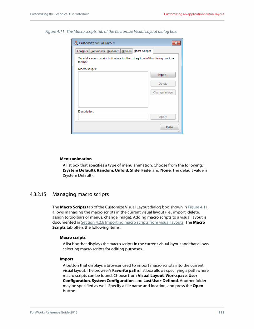
Customizing the Graphical User Interface
PolyWorks Reference Guide 2015 113
Customizing an application’s visual layout
Menu animationA list box that specifies a type of menu animation. Choose from the following: (System Default), Random, Unfold, Slide, Fade, and None. The default value is (System Default).
4.3.2.15 Managing macro scripts
The Macro Scripts tab of the Customize Visual Layout dialog box, shown in Figure 4.11, allows managing the macro scripts in the current visual layout (i.e., import, delete, assign to toolbars or menus, change image). Adding macro scripts to a visual layout is documented in Section 4.2.6 Importing macro scripts from visual layouts. The Macro Scripts tab offers the following items:
Macro scriptsA list box that displays the macro scripts in the current visual layout and that allows selecting macro scripts for editing purposes.
ImportA button that displays a browser used to import macro scripts into the current visual layout. The browser’s Favorite paths list box allows specifying a path where macro scripts can be found. Choose from Visual Layout, Workspace, User Configuration, System Configuration, and Last User-Defined. Another folder may be specified as well. Specify a file name and location, and press the Open button.
Figure 4.11 The Macro scripts tab of the Customize Visual Layout dialog box.
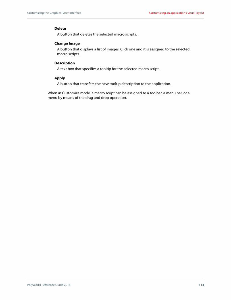
Customizing the Graphical User Interface
PolyWorks Reference Guide 2015 114
Customizing an application’s visual layout
DeleteA button that deletes the selected macro scripts.
Change ImageA button that displays a list of images. Click one and it is assigned to the selected macro scripts.
DescriptionA text box that specifies a tooltip for the selected macro script.
ApplyA button that transfers the new tooltip description to the application.
When in Customize mode, a macro script can be assigned to a toolbar, a menu bar, or a menu by means of the drag and drop operation.

5
PolyWorks Reference Guide 2015 115
Using the PolyWorks GUI
The PolyWorks IMAlign, IMEdit, IMInspect, and IMSurvey modules, as well as the PolyWorks|Viewer each provide their own graphical user interface featuring a 3D scene and interactive mouse-based operations. The five interfaces have been designed to work much the same way.
This chapter explains how to:
Use PolyWorks dialog boxes.
Specify templates used to read/write text files for import/export operations.
Transform the 3D scene.
Specify default material properties and lighting conditions.
Specify interface colors.
Configure modules.

Using the PolyWorks GUI
PolyWorks Reference Guide 2015 116
Using PolyWorks dialog boxes
5.1 Using PolyWorks dialog boxes
PolyWorks dialog boxes, such as the one in Figure 5.1, have the following particularities:
Clicking the ? on the title bar opens the reference documentation of the related module, in PDF format, to the correct section. The reference documentation provides the description of the dialog box, and may provide short procedures where relevant.
Changing a parameter value in a dialog box results in the parameter label being displayed in red. This alerts the user to changes that have been made to values. If the button that performs the operation is pressed, and the interface remains open, the strings are then all displayed in black.
5.2 Using a module’s Options dialog box
Most options for modules are located in a single options dialog box that is accessed by choosing the Tools > Options command on a module’s menu. An example of this dialog box is shown in Figure 5.2. Options are organized in pages which are offered in the following order: general options, display options, and object-specific or function-specific options. Click a page in the area to the left and its options are displayed in the area to the right.
To edit an option, access the option and enter a value. The label is displayed in red to be easily identifiable and to represent a nonapplied changed value. If the value is out of range or invalid, an error message is displayed (see Figure 5.2) that informs the user as to the valid data type (e.g., integer) or valid values (e.g., the range of values), depending on the context. Note that some changes made to an option are not displayed in red, such as when creating a new tolerance template in the IMInspect module; this means that the change has been saved and does not to be applied. When changing pages (i.e., clicking a different page) and an invalid value has been entered for an option, an error message is displayed and a valid value must be specified before a new page can be accessed.
Figure 5.1 A typical PolyWorks dialog box.

Using the PolyWorks GUI
PolyWorks Reference Guide 2015 117
Using a module’s Options dialog box
Press the Apply button to apply to the project changes made on all pages. Press the OK button to apply changes and close the dialog box. Press the Cancel button to close the dialog box, discarding any nonapplied changes.
To keep the changes in the project, the project must be saved either before or on closing. To transfer the changes to the user’s personal configuration file, choose the Tools > Save User Configuration command.
Note the following:
When returning to the options dialog box, it is opened to the page that was last used by the user. This is a general rule, but there are some exceptions where a command opens the dialog box to a specific page.
Figure 5.2 An example of a module’s option dialog box. The pages are listed to the left and the options for the selected page are shown to the right. Above, the Delay parameter has been modified and not yet applied, so it is shown in red. The user clicked on another page but as the changed Delay value is in error, an error message is displayed indicating the range of acceptable values. A valid value must be provided before moving to another page or applying changed values.

Using the PolyWorks GUI
PolyWorks Reference Guide 2015 118
Using a module’s Options dialog box
Changes to certain key options are immediately written to the user configuration as soon as they are applied to the project.
Some options are also located elsewhere, such as on toolbars or in dialog boxes. For example, the Point size (pixels) list box is offered on the Display page of the options dialog box as well as on the Object Display Options menu of the 3D Scene toolbar. Values in these cases are synchronized throughout the module.
In some cases (e.g., pressing the Edit Light Sources button on the Display > 3D Scene > Lights page) a separate dialog box is opened to make certain changes. In these cases, the changes made are applied on leaving the special dialog box and not on pressing the option dialog box’s Apply button.

Using the PolyWorks GUI
PolyWorks Reference Guide 2015 119
Reading and writing text files using templates
5.3 Reading and writing text files using templates
Certain object import operations require reading from text files, and certain export operations require writing to text files.
In most cases, context-specific templates are provided in the Template list box of a file browser or an options dialog box to configure reading the text file on import. While these templates serve most needs, it is possible to assign other existing templates to the list box and to create new templates.
5.3.1 Importing from text files
Text files can use the ASCII and/or Unicode encoding schemes, and as such include ASCII point clouds. When importing from text files, the file browser allows selecting one or more files, and then a dialog box offering import parameters may be displayed, like the one shown in Figure 5.3.
The Text files section offers the Template list box that offers a choice of context-specific templates for the importation of text files (text file templates). While most templates are straightforward, the ones included in the table that follows require additional description.
Templatename Description
IMAlign
CallidusThe Callidus template is specific to importing Callidus scans in the IMAlign module, and is detailed in the IMAlign Reference Guide.
3D Image Reference Points
One point to a line; each line contains three floating-point numbers describing the (x, y, z) coordinates of the point, followed by one string providing the name of the 3D image file to which the image reference point will be assigned.
Rotation CentersRotation Center includes a (x, y, z) center of rotation and the name of the 3D image in the IMAlign tree view that it corresponds to.
IMInspect, IMSurvey

Using the PolyWorks GUI
PolyWorks Reference Guide 2015 120
Reading and writing text files using templates
CmpPts + 2 Tol, CmpPts + 4 Tol
CmpPt (i.e., Comparison Point) represents (x, y, z) point coordinates and is the equivalent of Point. Tol stands for tolerance limit:2 Tol: represents two tolerance limits: LoTol then UpTol (e.g., -1 +1).4 Tol: represents four tolerance limits in the following order:LoTol, LoWarn, UpWarn, and UpTol (e.g., -1 -.5 .5 1).
Templatename Description
Figure 5.3 Import options offered when importing text files. The Template list box offers context-specific templates, and the Templates button allows adding text file templates to, and removing templates from, the default selection for the browser, as well as editing existing templates or creating new ones.

Using the PolyWorks GUI
PolyWorks Reference Guide 2015 121
Reading and writing text files using templates
If the choice of proposed templates does not meet your needs, press the Templates button to display a template management window that gives access to a list of all Available templates and the list of the Browser templates (see at the top in Figure 5.4). Use the Right arrow and the Left arrow to transfer templates from one list to the other.
Three buttons at the bottom of the dialog box can be used to manage user-defined templates:
EditA button that allows viewing the contents of standard text file templates, or editing user-defined text file templates.
DeleteA button that allows deleting user-defined text file templates.
NewA button that displays a dialog box that allows creating custom text file templates. On pressing the New button, the Add Text File Template dialog box is displayed (see Figure 5.4 (b)).
A template for reading a text file consists of the following elements:
A template name.
A header, which is the number of lines to skip at the beginning.
A line format.
A line format is described by a series of items from the Available items list box and transferred to the Active items list box by pressing the Left arrow button. Items in the Active items list box are ordered from top to bottom. Available items, grouped together in the table that follows when the information required is the same, include:
Item Description
Dummy NumberAn item that allows skipping a data item in the file that is a floating-point number.
Dummy TokenAn item that allows skipping a data item in the file that is not numerical.
Point (x, y, z)Point2 (x, y, z)B1 (x, y, z)B2 (x, y, z)
In each case, three successive floating-point numbers that provide the x, y, z coordinates of a point. B1 and B2 refer to points on the B-side objects in the context of flush & gap gauges.
Vector (i, j, k)Gap Vector (i, j, k)Tangent Vector (i, j, k)
Three successive floating-point numbers that provide the i component, the j component, and the k component of a vector.

Using the PolyWorks GUI
PolyWorks Reference Guide 2015 122
Reading and writing text files using templates
Color [0-255](r,g,b)Three successive integers, from 0 to 255 inclusively, that provide the R, G, B components of a color.
Image Name
A block of characters used by specific tools that provide a name. If the name is at the beginning or in the middle of a line format, it cannot contain spaces or tabs. If it is at the end of a line format, the name may contain spaces or tabs.
Item Description
Figure 5.4 (a) The dialog box used to specify a list of browser templates from a list of available templates. (b) The dialog box used to construct a new text file template.
Standard templates, which cannot be edited or deleted.
User-created templates, which can be edited or deleted.
(a)
(b)

Using the PolyWorks GUI
PolyWorks Reference Guide 2015 123
Reading and writing text files using templates
When a text file is read, PolyWorks only retains those lines whose format is compatible with the specified line format. Note that PolyWorks automatically discards characters that do not belong to numbers, except when a Name must be read. In such a case, the block of characters immediately following a number preceding the Name in the line format is considered to be the Name.
The Left arrow and Right arrow buttons in the dialog box are used to transfer items in and out of the Active items list box. The Up arrow and Down arrow buttons are used to move an item upward and downward in the Active items list box.
5.3.2 Exporting to text files
Exporting operations display a file browser very similar to the one shown in Figure 5.5. The following items may be offered when exporting objects/results to text files:
Intensity [0-255]An integer, from 0 to 255 inclusively, that provide an intensity or a level of gray.
Name
A block of characters used by specific tools that provide a name. If the name is at the beginning or in the middle of a line format, it cannot contain spaces or tabs. If it is at the end of a line format, the name may contain spaces or tabs.
Nominal LengthA floating-point number used by specific tools to provide a nominal value.
2 Tolerances
Floating-point numbers that provide two tolerance limits:• lower tolerance limit (i.e., LoTol)• upper tolerance limit (i.e., UpTol)
4 Tolerances
Floating-point numbers that provide four tolerance limits:• lower tolerance limit (i.e., LoTol)• lower warning limit (i.e., LoWarn)• upper warning limit (i.e., UpWarn)• upper tolerance limit (i.e., UpTol)
Radius A floating-point number that specifies a radius.
Horizontal IndexAn integer that specifies the horizontal index of a point in a point matrix.
Vertical IndexAn integer that specifies the vertical index of a point in a point matrix.
Item Description

Using the PolyWorks GUI
PolyWorks Reference Guide 2015 124
Reading and writing text files using templates
TemplateA list box that allows choosing a context-specific template used to write text files, including ASCII point clouds.
See the Exporting to text files section of the PolyWorks Reference Guide for more information on exporting to a text file.
Decimal symbolA list box that allows specifying the decimal symbol used to write the imported text file. Choose from: Point and Comma. The default value is Point.
Field delimitersA list box that allows specifying a field delimiter to use to write the text file. Choose from: Space, Tab, Semicolon, and Comma. The default value is Comma. If Comma is specified in the Decimal symbol list box, Semicolon is automatically selected.
Note that quotation marks can be used to maintain the integrity of the values in the file during the exportation process. For example, if the space is used as a field delimiter and if a name value has a space in it, the value should be in quotation marks to prevent exportation errors.
No. of digits after decimal symbolA text box that allows specifying the number of digits to use after the decimal symbol when writing to the text file. Valid values are integers that range from 1 to 15 inclusively. The default value is 6.
Scientific notationA check box that enables the use of scientific notation (e.g., 2.431E002 instead of 243.1). By default, the check box is cleared.
Figure 5.5 An example of the dialog box used to configure the number-writing method to use when exporting objects/results to a text file.

Using the PolyWorks GUI
PolyWorks Reference Guide 2015 125
Changing an object’s position, orientation, and projection
EncodingA list box that offers encoding methods. Choose from ASCII and Unicode. The default value is ASCII.
Press the OK button to transfer the specifications to the application and dismiss the dialog box, or the Cancel button to simply dismiss the dialog box.
5.4 Changing an object’s position, orientation, and projection
All six degrees of freedom needed to reach any desired position and orientation in 3D space can be accessed using the mouse in a very intuitive manner. Object-centered methods allow moving freely in 3D space. The mouse allows picking a 3D object and then rotating and translating the object. Using only the mouse, three translations and two rotations may be performed. One further rotation may be performed using the SHIFT key. Each operation is described in the subsections that follow.
In the default mode, several choices under the Mouse Button Behavior menu button on the 3D Scene toolbar are available to specify the allowed transformations in the 3D scene using the mouse, as shown in Figure 5.6.
To rotate about the X axis and the Y axis viewing axes, click and hold the left mouse button inside the 3D scene. Rotations are performed by moving the mouse in the desired directions. See Figure 5.7 (a). When a click occurs over a screen pixel belonging to a 3D surface, the (x, y, z) coordinates of the point are computed. The 3D scene is then rotated about the 3D location. If the click occurs over a background pixel instead of a surface pixel, the rotations are performed about the center of the bounding box. While rotating about the X axis and the Y axis, the pointer icon changes to the one shown to the right.
Figure 5.6 A menu offered on the 3D Scene toolbar, available in the default mode and other specific modes, that controls the transformations permitted in the 3D scene using the mouse.
Rotation Only
Rotation about View Axis Only
The first button allows access to all of the standard mouse-based rotation/translation/zoom operations. The other buttons assign one same operation to all of the mouse buttons, which is useful for new users who have not yet mastered the standard mode.
All operations
Translation Only
Zoom Box Only
Zoom Only

Using the PolyWorks GUI
PolyWorks Reference Guide 2015 126
Changing an object’s position, orientation, and projection
Rotations can also be constrained to a vertical or a horizontal viewing axis by pressing and holding down the SHIFT key before clicking. The decision to use the horizontal or the vertical axis is determined by the first 10-pixel displacement made with the mouse - if the displacement is close to the vertical axis, the rotation is performed about the horizontal axis, and if the displacement is close to the horizontal axis, the rotation is performed about the vertical axis. The pointer icon changes slightly, keeping only its vertical component or only its horizontal component.
5.4.1 Translating along the X and the Y viewing axes
To translate along the X axis and the Y axis, click and hold the middle mouse button. Translations along the X axis or the Y axis are performed by moving the mouse in the X or Y directions respectively, inside the 3D scene. See Figure 5.7 (b). While translating along the X axis and the Y axis, the pointer icon changes to the one shown to the right.
5.4.2 Translating along the viewing Z axis
Translating along the Z axis is equivalent to a zoom operation. This translation is illustrated in Figure 5.8 (a). Click and hold the right mouse button, then move the mouse forward and backward. When the mouse is moved forward, a positive
z
x
y
-x +x
-y
+y-x
+x
-y +y
Figure 5.7 Using the left and middle mouse buttons to change the position and orientation of a 3D object. In (a), the left mouse button is used to rotate the 3D object about the X axis and the Y axis. In (b), the middle mouse button is used to translate the 3D object along the X axis and the Y axis.
(a) (b)

Using the PolyWorks GUI
PolyWorks Reference Guide 2015 127
Changing an object’s position, orientation, and projection
translation is performed on the 3D object, and the scene moves nearer to the user. When the mouse is moved backward, a negative translation is performed on the 3D object, and the scene moves farther away from the user. While translating along the Z axis, the pointer icon changes to the one shown to the right.
Note that in the case of a mouse that has a wheel button as the middle button:
Rotating the wheel forward and backward will cause the 3D scene to, respectively, zoom in and zoom out using the current pointer position in the 3D scene.
Pushing and holding down the SHIFT key while rotating the wheel forward and backward will cause the 3D scene to, respectively, zoom in and zoom out using the center of the 3D scene.
The pointer does not change when zooming with the wheel button.
5.4.3 Rotating about the Z viewing axis
Press and hold down the SHIFT key to access this operation. Rotating about the Z axis is performed by clicking and holding the right mouse button, then moving the mouse in the right or left direction. See Figure 5.8 (b). While rotating about the Z axis, the pointer icon changes to the one shown to the right.
It is also possible to rotate the 3D scene by increments of 90 degrees about the viewing axis. The rotation is performed by holding down the SHIFT key and quickly right-clicking. If the right mouse button is held down for less than half a second, a counterclockwise rotation of 90 degrees is applied about the rotation axis. If the right mouse button is still down after half a second, the standard unconstrained rotation mode is activated.
5.4.4 Zooming by delimiting a rectangular area
In addition to zooming using the Z axis translation method, zooming can be performed on an object part by delimiting a rectangular area:
1. Press and hold the SHIFT key.
2. Middle-click to create a first rectangle corner.
3. Drag the pointer to the opposite rectangle corner.
4. Release the middle mouse button.
A zoom will operate on the delimited area. While zooming on the delimited area, the pointer icon changes to the one shown to the right.

Using the PolyWorks GUI
PolyWorks Reference Guide 2015 128
Setting material display options
5.4.5 Remaining in Dynamic display mode for several transformations
PolyWorks user interfaces use two display modes. The Dynamic display mode is used when the 3D scene is rotated and/or translated. The Static mode is applied when the 3D scene is not moved. Applications automatically switch between the Static and Display modes, depending on the actions of the user. To remain in the Dynamic display mode for a sequence of rotations and translations, press and hold the CTRL key. When the actions have stopped, and the CTRL key has been released, the display mode automatically switches back to the Static mode.
5.5 Setting material display options
The Display > 3D Scene > Material page of a module’s Options dialog box, accessed by choosing the Tools > Options command, offers the Edit Default Material button that displays a material-editing window that allows specifying the default material properties. The default material properties are used during the rendering process whenever an input model contains partial or no material specification. They specify values for material properties that are not specified within a file.
z
x
y
+ Shift key+z
-z
-z +z
Figure 5.8 Using the right mouse button to change the position and orientation of the 3D object. In (a), the right mouse button is used to translate the 3D object along the Z axis. In (b), the right mouse button enables rotation about the Z axis when the SHIFT key is pressed.
(a) (b)

Using the PolyWorks GUI
PolyWorks Reference Guide 2015 129
Setting material display options
The material-editing window for each module is similar to the one shown in Figure 5.9. Its initial settings are determined by the current application’s default material. It features a preview window featuring a sphere whose material is the currently edited material. Any editing is applied immediately to the preview area. Changes are applied to the 3D Scene immediately if the Automatically apply changes to the 3D scene check box is selected; otherwise, changes are applied when the Apply or the OK button is pressed.
The preview window uses the OpenGL material model in which a material is defined by color, transparency, and shininess:
ColorsA group box that offers the following editable colors:
AmbientA color box that specifies how ambient light is reflected.
DiffuseA color box that specifies how diffuse light is reflected.
EmissiveA color box that specifies the color emitted by the material.
Figure 5.9 The Edit Default Material window.
Using the PolyWorks GUI
PolyWorks Reference Guide 2015 130
Setting material display options
SpecularA color box that specifies the color of specular highlights.
To edit a color, click its color box. The window shown to the right in Figure 5.9 is displayed, featuring a color rectangle and an adjacent intensity slider. Colors are modified by moving the color pointer within the color rectangle. The slider controls color intensity. The New and the Current colors are displayed to the bottom right. Press the OK button to transfer the new color to the application and to close the window, or press the Cancel button to end the operation.
TransparencyA slider that specifies material transparency (does not apply to IMInspect). When the slider is located to the extreme left, there is no transparency (0%), and when located to the extreme right, the transparency is at its maximum (100%).
ShininessA slider that specifies the size and brightness of specular highlights. When the slider is located to the extreme left, there is no shininess (0%), and when located to the extreme right, the shininess is at its maximum (100%).
Two buttons allow loading and saving material setup files:
Load SettingsA button that displays a standard file browser to load a material file. Specify a file name and location; the standard extension is .mat. In the browser’s Favorite paths list box, choose from User Configuration and System Configuration, or Last User-Defined. Press the Open button to load the file, or press the Cancel button to end the operation.
Save SettingsA button that displays a standard file browser to save the current material settings to a material file. In the browser’s Favorite paths list box, choose from User Configuration and System Configuration, or Last User-Defined. Specify a file name and location and press the Save button, or press the Cancel button to end the operation.
The bottom section of the dialog box offers a check box and four buttons:
Automatically apply changes to the 3D sceneA check box that enables automatically transferring the new material definition to the application without having to press the Apply button. The check box is selected by default.
OKA button that transfers the new material definition to the application and dismisses the material-editing window.
CancelA button that replaces the current material definition by the material definition in use at the time the Edit Default Material window was opened, and dismisses the material-editing window.

Using the PolyWorks GUI
PolyWorks Reference Guide 2015 131
Setting lighting display options
ApplyA button that transfers the new material definition to the application. It is available when the Automatically apply changes to the 3D scene check box is cleared.
ResetA button that replaces the current material definition by the initial material definition. The button is only available if a specification was made that changes the material definition.
5.6 Setting lighting display options
PolyWorks interfaces can use up to four directional light sources for 3D rendering. Light sources are edited by pressing the Edit Light Sources button on the Display > 3D Scene > Lights page of a module’s Options dialog box. On pressing the button, a light-editing tool, like the one shown in Figure 5.10, is displayed. The initial settings of the light-editing window are determined by the application’s current light source definitions. Specifications may be made for up to four directional light sources.
The tool is organized as follows. The upper-left section of the window displays a preview area containing a sphere whose material is the application’s Default Material. Any changes made to an active light source, for example its position or colors, are applied immediately to the preview area. Changes are applied to the 3D scene immediately if the Automatically apply changes to the 3D scene check box is selected; otherwise, changes are applied when the Apply or the OK button is pressed.
In the preview area, the sphere is rendered using the current light sources. Each active directional light source is modeled by a 3D arrow oriented along the light source orientation vector. The orientation of a light source is modified as follows: click the 3D arrow that has the number of the light source (the pointer is automatically repositioned at the arrow’s extremity onto the sphere) and drag the pointer until the desired orientation is reached.
The Light positioning group box offers items that allow constraining the light source orientation:
Angular stepA check box that enables constraining the light source orientation. It is cleared by default. When selected, the orientation vector pan angle and elevation angle may be rounded up to the following common integer values:
15 degreesAn option button that specifies that the pan and elevation angles are rounded up to multiples of 15 degrees.
30 degreesAn option button, selected by default, that specifies that the pan and elevation angles are rounded up to multiples of 30 degrees.

Using the PolyWorks GUI
PolyWorks Reference Guide 2015 132
Setting lighting display options
45 degreesAn option button that specifies that the pan and elevation angles are rounded up to multiples of 45 degrees.
The table in the middle section allows activating and editing light sources and editing light source colors. The four check boxes to the left are used to activate or deactivate light sources. The Ambient, Diffuse, and Specular columns offer those colors for each light source. They can be edited by first clicking a color box to display the Colors dialog box (see to the right in Figure 5.10) and then modifying the color by moving the color pointer within the color rectangle and moving the adjacent intensity slider. The New and the Current colors are displayed to the bottom right. Press the OK button to transfer the new color to the application and to close the dialog box, or press the Cancel button to end the operation.
Two buttons below the table allow loading and saving light source files:
Load SettingsA button that displays a standard file browser to load a light source file. Specify a file name and location; the standard extension is .lit. In the browser’s Favorite paths list box, choose from User Configuration and System Configuration, or Last User-Defined. Press the Open button to load the file, or press the Cancel button to end the operation.
Figure 5.10 The Edit Light Sources window.

Using the PolyWorks GUI
PolyWorks Reference Guide 2015 133
Configuring interface colors
Save SettingsA button that displays a standard file browser to save the current light settings to a light source file. In the browser’s Favorite paths list box, choose from User Configuration and System Configuration, or Last User-Defined. Specify a file name and location and press the Save button, or press the Cancel button to end the operation.
The bottom section contains a check box and four buttons:
Automatically apply changes to the 3D sceneA check box that enables automatically transferring the new light source definitions to the application, without having to press the Apply button. The check box is selected by default.
OKA button that transfers the new light source definitions to the application and dismisses the light-editing window.
CancelA button that replaces the current light source definitions by the initial light source definitions and dismisses the light-editing window.
ApplyA button that transfers the new light source definitions to the application. It is available when the Automatically apply changes to the 3D scene check box is cleared.
ResetA button that replaces the current light source definitions by the light source definition in place at the time the Edit Light Sources window was opened. The button is only available if a specification was made that changes the light definition.
5.7 Configuring interface colors
Each PolyWorks application has its own set of interface colors. Examples of interface colors include the color used to fill the 3D scene, the color used to render selections, and the color used to render a bounding box. All of these colors are customizable and can be modified by way of the Display > Interface Colors page of a module’s Options dialog box, which can be accessed by choosing the Tools > Options command. The dialog box for the IMAlign module is shown in Figure 5.11.
To edit an interface color, click its adjacent color box and click a color in the list that is displayed. Press the OK button to transfer the new values to the application and to close the dialog box. To apply the changes to the user configuration, choose the Tools > Save User Configuration command. The current configuration will become the new user configuration.

Using the PolyWorks GUI
PolyWorks Reference Guide 2015 134
Configuring PolyWorks interfaces
5.8 Configuring PolyWorks interfaces
PolyWorks user interfaces may easily be configured to your specific needs by saving dialog box sizes and positions, display modes, and color information in an application’s configuration file. Configuration files are read when the applications are started. All applications have a Tools menu that offers interface configuration. It contains at least the two following commands:
OptionsOpens a dialog box that manages the options for the module or the PolyWorks Workspace Manager.
Save User ConfigurationSaves the current configuration to the user’s configuration file.
Figure 5.11 The Display > Interface Colors page of the IMAlign Options dialog box.

A
App
endi
x
PolyWorks Reference Guide 2015 135
Managing Floating Servers and Floating Client Computers
This chapter provides additional information on managing floating servers and floating client computers.
For complete information concerning the FlexNet license management software and its utilities, refer to the FlexNet License Administration Guide in the PolyWorksInstallationFolder\documentation\FLEXnet subfolder.

Managing Floating Servers and Floating Client Computers
PolyWorks Reference Guide 2015 136
Floating licenses
A.1 Floating licenses
The floating license scheme permits the licenses to float on the network and be used by any computer on that network, as shown in Figure A.1. InnovMetric Software uses the FlexNet license management software from Flexera Software Inc.
The licensing software on the server publishes the licenses available for use on the network. Licenses are reserved on a first come, first-served basis. Once a license is in use on a client computer, it is no longer available to the other client computers. Note that one license is used per module per client computer, no matter the number of instances of the same module that may be open at once on the client computer. If you have purchased a full PolyWorks license, more than one user can be using the same license, providing that they are working on different modules.
For more information concerning the FlexNet license management software and its command-line utilities, refer to the FlexNet License Administration Guide in the PolyWorksInstallationFolder\documentation\FLEXnet subfolder.
A.1.1 Introducing floating license key files
The floating license server must be activated by installing a license key file (floating.lic) on the computer hosting the license server. There are two types of license key files for floating license servers:
Figure A.1 An example of the floating license scheme.
PolyWorks can run on any computer of this network
Server computer(s), with floating server installation
Client computers, with floating client installation

Managing Floating Servers and Floating Client Computers
PolyWorks Reference Guide 2015 137
Managing floating license servers
The license key file can be created using the MAC address of the computer hosting the license server. In this case, simply install the license key file to activate the license server.
The license key file can be created using a FlexNet dongle ID. In this case, install both the license key file and the USB dongle to activate the license server. The dongle must remain connected to the computer hosting the license server at all times.
A.1.2 Accessing the IMKey tool
The IMKey tool allows managing the floating license server and the floating client computers.
If the License Server for PolyWorks application is installed on the computer hosting the floating license server manager application, double-click its icon on your desktop to open the IMKey dialog box.
Otherwise, proceed using the PolyWorks Workspace Manager. Double-click the PolyWorks icon on your desktop (see in the right margin). The PolyWorks Workspace Manager is displayed. The IMKey dialog box may appear automatically. If not, choose the Tools > IMKey License Management command, or click the IMKey License Management button (shown to the right) on the Standard toolbar.
A.2 Managing floating license servers
This section explains how to manage floating license servers using the PolyWorks IMKey tool and special command-line utilities. These operations must be performed on the computer hosting the floating license server.
Floating license server management operations are located on the Floating keys - Server tab of the IMKey dialog box, as shown in Figure A.2. They include obtaining the license key file, activating the floating license server, installing new floating license keys, getting information concerning attributed licenses, and managing the floating license server’s status.
Note that certain management operations can only be run as an administrator, including starting, stopping, and reinstalling the server as well as importing floating license key files.
A.2.1 Obtaining the floating license key file
The floating license key file (floating.lic) is used to install the license keys on the floating license server. To obtain the file, follow these steps:

Managing Floating Servers and Floating Client Computers
PolyWorks Reference Guide 2015 138
Managing floating license servers
1. Log on to the computer hosting the license server application.
2. Open the IMKey dialog box (see Section A.1.2 Accessing the IMKey tool).
3. Open the Floating keys - Server tab.
Note that this is the default and only tab when using the License Server for PolyWorks.
4. Proceed as follows:
If you are using the MAC address of the computer hosting the license server, clear I have a USB dongle.
Figure A.2 The Floating keys - Server tab of the IMKey dialog box.

Managing Floating Servers and Floating Client Computers
PolyWorks Reference Guide 2015 139
Managing floating license servers
If you are using a FlexNet USB dongle, make sure it is connected, and select I have a USB dongle.
If FlexNet hostid indicates “No USB dongle is detected”, check that the dongle is connected, then click Refresh to update the FlexNet hostid. If the problem persists, contact InnovMetric Software for technical support.
5. Press Copy to Clipboard to copy your FlexNet hostid and your Server name, or note the information.
6. Send your FlexNet hostid and your Server name by e-mail to your PolyWorks provider. You can paste this information in your e-mail if you copied the information to the clipboard.
7. Your PolyWorks provider will then send you the license key file (floating.lic).
A.2.2 Activating the floating license server
In order to allow client computers to use the licenses distributed by the server, the floating license server must be activated by first importing the license key file, and then by starting the license server.
On obtaining the floating.lic license key file, follow these steps:
1. Log on to the computer hosting the license server application. Make sure you are logged in as the Administrator user; the operations that follow can only be run as an administrator.
2. Open the IMKey dialog box (see Section A.1.2 Accessing the IMKey tool).
3. Open the Floating keys - Server tab.
Note that this is the default and only tab when using the License Server for PolyWorks.
4. Press Import License Key File and browse for the floating license key file (floating.lic) sent by your PolyWorks provider. In the browser, click Open. The file will automatically be copied to the installation folder
5. When prompted to start the license server, click Yes. You can also click Start to start the local license server.
When installing new license keys for the same version of PolyWorks, or for a new version of PolyWorks, a message window is displayed asking to restart the license server. Click Yes; any applications in use may be terminated. If you click No, you will return to the previous screen.

Managing Floating Servers and Floating Client Computers
PolyWorks Reference Guide 2015 140
Managing floating license servers
A.2.3 Getting information on attributed licenses
The Floating keys - Server tab of the IMKey dialog box offers a License keys area that lists the PolyWorks modules for which license keys have been imported as well as the number of licenses available for each. It also indicates how many licenses are being used for each application and who is using them. To view the complete list of users, place the pointer over the corresponding module under the Module column. A tooltip will appear listing the current users.
Press the Refresh button to update the License keys list as well as all server-related information.
A.2.4 Releasing licenses
To force the release of a license key from a client, open a Command window on the computer that is the server, go to the bin subfolder of the PolyWorks installation folder, and give the following command:
imlm_clean feature user host display
where feature, user, host, and display are provided by the imlm_info command.
For more information, refer to the FlexNet License Administration Guide.
A.2.5 Managing the floating license server status
The Status text box on the Floating keys - Server tab of the IMKey dialog box specifies the server status indicating whether the server is running or not.
It may also indicate whether the license server is installed or not. If the message indicates that the license server is not installed, press the Reinstall button to reset the license server to its initial state. Note that reinstalling the server can only be done as an administrator, and it will abruptly terminate any active PolyWorks application.
Press the Start button to start the server and make available the PolyWorks modules. Note that starting the server can only be done as an administrator. Press the Stop button to stop the server. A message window is displayed asking to confirm the operation. Note that stopping the server can only be done as an administrator, and it will abruptly terminate any active PolyWorks application.
A.2.6 Exporting the license server log (troubleshooting)
If problems occur with the floating license server, the license server log can be exported to help diagnose the problem. For technical support, send the .log file directly

Managing Floating Servers and Floating Client Computers
PolyWorks Reference Guide 2015 141
Managing floating license servers
to your PolyWorks provider, or to the InnovMetric Software technical support team by e-mail at [email protected].
To export the .log file, proceed as follows:
1. Log on to the computer hosting the license server application.
2. Open the IMKey dialog box (see Section A.1.2 Accessing the IMKey tool).
3. Open the Floating keys - Server tab.
4. Press the Export Log button.
The Export License Server Log browser is displayed to specify a file name and a location on disk, as shown in Figure A.3.
5. Send the .log file directly to your PolyWorks provider, or to the InnovMetric Software technical support team by e-mail at [email protected]
Figure A.3 The Export License Server Log browser.

Managing Floating Servers and Floating Client Computers
PolyWorks Reference Guide 2015 142
Managing floating license clients
A.3 Managing floating license clients
This section explains how to manage floating client computers using the PolyWorks IMKey tool and special command-line utilities.
A.3.1 Defining floating server names
Client computers must provide the license server name from which licenses are to be used.
To define or redefine the floating server names, proceed as follows:
1. Enter the server name in the Name text box found under the License server group box of the Floating keys - Client tab of the IMKey dialog box, shown in Figure A.4.
This computer name will be used by PolyWorks to contact the floating license server and to obtain licenses:
For single server installations, use @server, where server is the computer’s name as recognized by the network. Or, specify the server’s TCP port number before the @ symbol (e.g., 27000@server).
For networks with multiple servers, specify their names separated by a “;” (e.g., @server1;@server2). Or, specify the servers’ TCP port number before the @ symbol (e.g., 27000@server1;27001@server2).
For triad networks, specify the servers’ TCP port number before the @ symbol, and specify the servers’ names separated by a “,” (e.g., 27000@server1,27001@server2,27003@server3).
Press Apply.
If unable to define the floating server names using these methods, see Section A.3.1.1 Defining floating server names using their IP address (troubleshooting).
A.3.1.1 Defining floating server names using their IP address (troubleshooting)
Floating server names can be defined using their IP address. Instead of specifying the server’s name, simply specify its IP address after the @ symbol (e.g., @192.168.0.2).
This method should only be used to address troubleshooting issues since IP addresses may change over time.

Managing Floating Servers and Floating Client Computers
PolyWorks Reference Guide 2015 143
Managing floating license clients
A.3.2 Obtaining a floating client license server status
The Status text box found under the License server group box of the Floating keys - Client tab of the IMKey dialog box offers information regarding the license server status (see Figure A.4), including:
Whether the client computer is connected to the server computer.
Whether the license server is started on the server computer.
Whether the server computer is detected or responding.
Figure A.4 The dialog box used to configure a client computer and obtain license key information.

Managing Floating Servers and Floating Client Computers
PolyWorks Reference Guide 2015 144
Managing floating license clients
If a problem regarding the connection to the server computer occurs, press the Details button to obtain a detailed error message provided by FlexNet.
A.3.3 Getting information on attributed licenses
The License keys group box of the Floating keys - Client tab of the IMKey dialog box offers two option buttons to list either the license keys available on the server (see Figure A.4) or the licenses borrowed by the user (see Figure A.5):
Available on serverAn option button that lists the PolyWorks modules for which license keys have been imported as well as the total number of licenses available for each. It also indicates how many licenses are being used for each module and who is using
Figure A.5 A list of borrowed license keys.

Managing Floating Servers and Floating Client Computers
PolyWorks Reference Guide 2015 145
Managing floating license clients
them. Note that if a used license has been borrowed, it is specified in the Users column along with the return date and time. To view the complete list of users, place the pointer over the corresponding module under the Module column. A tooltip will appear listing the current users.
This item also makes available the Borrow button that, when pressed, displays the Floating License Borrowing dialog box, shown in Figure A.6, for borrowing selected licenses. It offers the Return by combo boxes that specify the return date and time respectively. By default the return date and time is 24 hours later. Press the OK button to launch the borrowing operation, or press the Cancel button to dismiss the dialog box. Note that only available licenses can be borrowed. Select the Borrowed option button to view the list of licenses borrowed locally by the current user.
BorrowedAn option button that lists the PolyWorks modules for which licenses have been borrowed by the current user on the local client computer as well as the Expiration date and time. This item also makes available the Return button that, when pressed, returns selected borrowed licenses to the server before the expiration date and time.
Borrowed licenses remain available on the client computer when it is disconnected from the server. To return licenses, the client computer must be connected to the server.
Press the Refresh button to update the License keys list as well as all server-related information.
Figure A.6 The dialog box used to borrow floating licenses.

B
App
endi
x
PolyWorks Reference Guide 2015 146
Group Directory Format Specification
A group directory format has been defined in PolyWorks. The purpose of this directory format is to provide support for communicating information between different applications that use multiple 3D images. The specification given in this appendix presents the public ASCII part of the directory format. PolyWorks also writes binary files in a group directory but their format is not documented here.

Group Directory Format Specification
PolyWorks Reference Guide 2015 147
The Group Directory format
B.1 The Group Directory format
The ASCII files in a group directory contain information packets that provide specific information about the set of 3D images. All information packets are specified in the following way:
TYPE_OF_INFORMATION = specified_information <nl>
- TYPE_OF_INFORMATION is an identifier written in capital letters that indicates the nature of the specified information.
- The identifier is followed by the equal sign.
- The specified information follows the equal sign. Symbol <nl> indicates a new line.
Note that an information line can contain at most 512 characters. It is possible to add comments to an ASCII file by starting a line with the ‘#’ character.
B.1.1 Information file for the group
A group directory must include a file called info. File info contains two information packets.
NB_IMAGES = number_of_images <nl>
- number_of_images is an integer number specifying the number of 3D images in the group directory.
VERSION = version_string <nl>
- version_string specifies the version of PolyWorks that has created the file.
B.1.2 Information files for the images
An information file has to be created for each image in the group directory. If there are N images in the group, N image information files must be created under the generic file name image%d, where %d ranges from 0 to N-1.
Eleven documented types of information packets can be specified in an image information file. The order in which these packets are specified is not important.
The first two types of information packets specify the 3D image file name and format:

Group Directory Format Specification
PolyWorks Reference Guide 2015 148
The Group Directory format
FILENAME = image_file_name <nl>
- image_file_name is a string specifying the absolute path name of the 3D image.
FORMAT = image_format <nl>
- image_format is a string specifying the 3D image file format.
The next four types of information packets describe the interpolation parameters applied to the original 3D image:
I_SCALE = i_scale_value <nl>
- i_scale_value is a floating-point number specifying the parametric distance between two horizontal neighbors in the interpolated 3D image. It is specified in image units, for a planar image, or in degrees, for a cylindrical image.
J_SCALE = j_scale_value <nl>
- j_scale_value is a floating-point number specifying the parametric distance, in image units, between two vertical neighbors in the interpolated 3D image. If the 3D image is planar, j_scale_value should be equal to i_scale_value.
MAX_ANGLE = max_angle_value <nl>
- max_angle_value is a floating-point number specifying a maximum angle, in degrees, between a surface normal vector and the Z axis of the parameterized 3D image coordinate system. This threshold is used to detect discontinuities in a 3D image.
SWING_ANGLE = swing_angle_value <nl>
- swing_angle_value is a floating-point number specifying a rotation angle about the Z axis, in degrees. This rotation angle is applied to the raw 3D image prior to its interpolation.
The alignment transformation matrices computed by IMAlign are also saved in the image information files in the following manner:
TRANSFORMATION_MATRIX = <nl>
m1 m2 m3 m4 <nl>m5 m6 m7 m8 <nl>m9 m10 m11 m12 <nl>m13 m14 m15 m16 <nl>
- The TRANSFORMATION_MATRIX identifier is used to specify a 4x4 image transformation matrix. The sixteen matrix elements are written as floating-point

Group Directory Format Specification
PolyWorks Reference Guide 2015 149
The Group Directory format
numbers in either single or double precision. The 4x4 matrix is a standard rigid transformation matrix:
Matrix M performs three rotations and three translations, and results from the multiplication of a 4x4 translation matrix T and a 4x4 rotation matrix R. Matrix M premultiplies the 3D image points in order to transform a local image coordinate system into a global coordinate system into which the whole set of 3D images is transformed.
Finally, there are four miscellaneous types of information packets:
IMAGE_COLOR = red green blue alpha <nl>
- red, green, blue and alpha color components are specified as floating-point numbers whose values are normalized between 0.0 and 1.0. These color components define a global color for the 3D image.
INVERT_IMAGE = flag_value <nl>
- If flag_value is set to 1, the 3D image orientation is inverted. A zero value indicates a normal image.
SUBGROUP_ID = subgroup_id_value <nl>
- subgroup_id_value is an identifier that indicates the subgroup to which a 3D image belongs. During the alignment optimization process, the relative alignment of the 3D images that belong to a given subgroup is preserved. If n_subgroups subgroups are defined, their identifiers must be 0, 1, 2, ..., n_subgroups-1.
Z_MIN = z_min_value <nl>
- z_min_value is a floating-point number specifying a minimum z value for a planar 3D image.
M
m1 m2 m3 m4
m5 m6 m7 m8
m9 m10 m11 m12
m13 m14 m15 m16
r1 r2 r3 tx
r4 r5 r6 ty
r7 r8 r9 tz
0 0 0 1
TR= = =

C
App
endi
x
PolyWorks Reference Guide 2015 150
POL – A Binary File Format for Polygonal Models
InnovMetric Software has devised POL, a binary file format that allows the description of polygonal models with grouping information, material definitions, and texture images. A key feature of the POL format is that it supports the description of multicontour, simple planar polygons. This appendix gives a complete description of the POL format. Note that POL files must be written using a big-endian byte-ordering scheme.

POL – A Binary File Format for Polygonal Models
PolyWorks Reference Guide 2015 151
Fundamentals
C.1 Fundamentals
Multicontour polygons
POL supports the description of multicontour polygons. A multicontour polygon is defined by one external contour and a series of internal contours that trim the area enclosed by the external contour.
If no internal contours are defined, the area enclosed by the external contour is a direct facet of the polygonal model. An example of a single contour polygon is shown in Figure C.1 (a). When internal contours are defined, they either remove or add an area to the facet represented by the polygon. Internal contours that are not enclosed in any other internal contours are considered holes. In this way, they remove the area they enclose from the polygonal model.
Moreover, internal contours can be defined inside a hole to create an “island”. These island contours cancel the hole and add the area they enclose to the polygonal model. Thereafter, holes can be defined inside islands and so on. Up to 128 levels of contour enclosing can be specified in the POL format. Figure C.1 (b) shows an example of a multicontour polygon with two holes and one island.
Simple polygon constraint
Only simple polygons should be described in the POL format. A polygon is simple if its edges intersect at vertices only, if there are no duplicate vertices, and if exactly two edges meet at any vertex.
Planar polygon constraint
Polygons described in the POL format should be planar polygons. A planar polygon is a polygon for which all vertices lie on a common plane. When a polygon is planar, it is possible to fit a plane to its vertices and use this fitted plane to triangulate the interior of the polygon.
Counterclockwise order constraint for the external contour
To determine the orientation of the polygons, the external contour of every multicontour polygon description must be specified in counterclockwise order according to the right-hand rule.

POL – A Binary File Format for Polygonal Models
PolyWorks Reference Guide 2015 152
Specification of the POL format
C.2 Specification of the POL format
POL format files are identified by the “.pol” extension. A POL file may comprise up to five blocks of information. The first block is a header that contains information about the file structure. Following the header, a second block of information contains the set of 3D geometric vertices of the polygonal model. A third block then contains the description of the model polygons. The fourth block of a POL file contains color or texture information and is optional. Finally, the fifth block describes grouping information and contains group attributes, such as material definitions and texture images.
The rest of this section explains the structure of each block of information in a POL file. This specification assumes that the long data type is 4 bytes long.
C.2.1 Block 1: Header
The header part of a POL file is 512 bytes long and contains useful information for reading the rest of the file. The following structure may be used to read the header of a POL file (C language syntax):
struct header{char format_version[64];char user_comments[128];char dummy1[4];long nv;
0
12
34
5
6 7
89
10
12 11
13
14 15
16
17
18
Figure C.1 In (a) a single contour polygon. In (b) a multicontour polygon with two holes and an island.
(a) A single contour polygon
(b) A multicontour polygon

POL – A Binary File Format for Polygonal Models
PolyWorks Reference Guide 2015 153
Specification of the POL format
long vblock_length;long np;long pblock_length;long color_texture_flag;long ctblock_length;long ngr;long grblock_length;long dummy2[71];};
format_version: A 64-byte field reserved for an identifier string which gives the name of the format and the version number. String “POL Format v2.0” must be written in this field.
user_comments: A 128-byte field that can be used to write information about the model.
dummy1: A 4-byte field that may be used for special characters.
nv: Number of vertices in the file.
vblock_length: Length in bytes of the block containing the vertices.
np: Number of polygons described in the file.
pblock_length: Length in bytes of the block containing the polygons.
color_texture_flag: A flag indicating color or texture information. All color or texture information is given in the optional fourth block following the block of polygons.
If 0, there is no color or texture information;
If 1, RGB colors are defined for each vertex of the polygonal model;
If 2, RGBA colors are defined for each vertex of the polygonal model;
If 3, two texture coordinates are defined for each polygon vertex.
ctblock_length: Length of the color or texture block in bytes.
ngr: Number of groups in the file.
grblock_length: Length of the group block in bytes.
dummy2: Space reserved for future use.

POL – A Binary File Format for Polygonal Models
PolyWorks Reference Guide 2015 154
Specification of the POL format
C.2.2 Block 2: List of vertices
This block contains vblock_length bytes of information. It contains a list of nv vertices. Each vertex is specified by 3 floating-point numbers representing its x, y, z coordinates. Reading the list of vertices may be done by reading a block of nv vertex structures (C language syntax):
struct vertex{float x;float y;float z;};
C.2.3 Block 3: List of polygons
This block contains pblock_length bytes of information. It may be read as a block of pblock_length/4 integer numbers of type long. This section of a POL file consists of a list of np polygons. Each polygon vertex is represented by an integer number which indicates a vertex position in the list of vertices. Therefore, a polygon vertex can take values from 0 to nv-1.
The first parameter in the description of a multicontour polygon is the number of contours:
long nc; /* number of contours */
The number of contours must be larger than or equal to 1. After this comes a list of nc contour descriptions. The first contour must be the external contour. The order in which the internal contours are specified is not important. A contour description is made of two parts. The first part is an integer number representing the number of contour vertices:
long ncv; /* number of contour vertices */
The second part of a contour description consists of a list of ncv contour vertices. The vertices of the external contour must be given in counterclockwise order. As for the internal contours, they can be either expressed in clockwise or counterclockwise order. A vertex is an integer number:
long v; /* a given vertex */
Example of a multicontour polygon
Let us consider the multicontour polygon of Figure C.1 (b). Assuming that the indexes next to the polygon vertices correspond to positions in the list of vertices, this polygon would be described in a POL file as follows:
4 /* Number of polygon contours */6 /* Number of vertices in external contour */

POL – A Binary File Format for Polygonal Models
PolyWorks Reference Guide 2015 155
Specification of the POL format
4 /* External contour vertices in counterclockwise order */531203 /* Number of vertices in internal contour 1 */16 /* List of contour vertices */17184 /* Number of vertices in internal contour 2 */6 /* List of contour vertices */7896 /* Number of vertices in internal contour 3 */10 /* List of contour vertices */1214151113The long data type is used for all integer numbers in a POL file.
C.2.4 Block 4: Optional color or texture information
This optional block contains ctblock_length bytes of information. The block is padded to ensure that its length is a multiple of 4. The contents of the block depends on the value of color_texture_flag. If this flag is set to 0, the block is empty.
If color_texture_flag is set to 1, the block contains three bytes of color information for each geometric vertex described in block 2. The three bytes represent the RGB components of the vertex color. RGB components contained in the block are interlaced as follows:
RGBRGBRGBRGB...
If color_texture_flag is set to 2, the block contains four bytes of color information for each geometric vertex described in block 2. The four bytes represent the RGBA components of the vertex color. RBGA components contained in the block are interlaced as follows:
RGBARGBARGBARGBA...
If color_texture_flag is set to 3, the block contains 2D texture coordinates for each polygon vertex specified in block 3. The block then contains ctblock_length/4 floating-point numbers. For each polygon vertex, two floating-point numbers give x and y texture coordinates. Texture coordinates must be normalized between 0 and 1 for both axes. The texture image onto which each polygon is mapped is determined by the group to which the polygon belongs.

POL – A Binary File Format for Polygonal Models
PolyWorks Reference Guide 2015 156
Specification of the POL format
C.2.5 Block 5: Grouping information
This block contains grblock_length bytes of information. It describes ngr groups of triangles. A group is a set of triangles whose indexes are contiguous in memory, and that share common properties, such as a material definition and a texture image. Reading the group of triangles in a POL file may be done by reading a block of ngr group structures (C language syntax):
struct group{long poly_begin;long poly_end;long mat_default;float mat_diffuse[4];float mat_ambient[3];float mat_specular[3];float mat_emissive[3];float mat_shininess;char name[256];char texmap[256];};
poly_begin: Index of the group’s first polygon
poly_end: Index of the group’s last polygon
mat_default: A flag indicating the validity of each material attribute. The first, second, third, fourth, and fifth bits of the flag respectively address the diffuse color, ambient color, specular color, emissive color, and shininess attributes. When the bit is set to 1, the corresponding attribute is invalid, and the application should use a default setting for the attribute.
mat_diffuse: The first three floating-point numbers provide the R, G, B components of the material’s diffuse color. Colors are normalized between 0 and 1. The fourth floating-point number indicates the material transparency. A value 0.0 represents full transparency while a value of 1.0 represents an opaque material.
mat_ambient: The three floating-point numbers provide the R, G, B components of the material’s ambient color. Colors are normalized between 0 and 1.
mat_specular: The three floating-point numbers provide the R, G, B components of the material’s specular color. Colors are normalized between 0 and 1.
mat_emissive: The three floating-point numbers provide the R, G, B components of the material’s emissive color. Colors are normalized between 0 and 1.

POL – A Binary File Format for Polygonal Models
PolyWorks Reference Guide 2015 157
Specification of the POL format
mat_shininess: The floating-point number represents the material’s shininess attribute. Its value ranges from 0 to 128. Refer to OpenGL’s documentation for additional information.
name: A group name.
texmap: A texture image file name. Windows naming conventions are valid. A relative path should be used when the texture image is part of the same folder structure in which the POL file is created. Relative paths allow the POL file and its related texture images to be transferred to another system. Absolute paths can also be used. When an empty string is specified, the group has no texture image, and texture coordinates for the group polygons are ignored.

D
App
endi
x
PolyWorks Reference Guide 2015 158
Parametric Image Format – PIF
InnovMetric Software has devised PIF, a binary file format for describing 3D parametric images. This appendix introduces the concept of parametric images and gives a complete description of the PIF format. Note that PIF files must be written using a big-endian byte-ordering scheme.

Parametric Image Format – PIF
PolyWorks Reference Guide 2015 159
Fundamentals
D.1 Fundamentals
In this appendix, a parametric image is defined as a 3D surface mesh that can be mapped and interpolated onto a 2D parametric space. The PIF format supports the definition of planar and cylindrical 2D parametric spaces. It should be noted, however, that PolyWorks does not support cylindrical images.
D.1.1 Planar and cylindrical parametric images
A planar image consists of a 3D surface mesh that can be mapped onto the 2D parametric space of a plane. A cylindrical image consists of a 3D surface mesh that can be mapped onto the 2D parametric space of a cylinder. Examples of planar and cylindrical images are shown in Figure D.1.
D.1.2 Raw and interpolated parametric images
In this document, a raw parametric image is defined as a 3D surface mesh measured by a 3D imaging device. A raw parametric image is described by a set of (x, y, z) point coordinates and the connectivity information between these points. There are two ways to specify a raw parametric image in the PIF format. A 3D surface mesh can be described by an array of data points or by a polygonal mesh. As shown in Figure D.2 (a) and (b), the data points in a raw parametric image need not be distributed in any particular way in the 2D parameterization space.
For several algorithms used in the PolyWorks modules, however, it is more convenient to describe a 3D surface mesh by an array of data points distributed on a square grid in the 2D parameterization space (see Figure D.2 (c)). In this document, a parametric image parameterized on a square grid is called an interpolated parametric image. PolyWorks provides interpolation routines to transform raw parametric images into interpolated parametric images.
D.2 Coordinate systems in the PIF format
Three coordinate systems are used in the PIF format, as depicted in Figure D.3. This section describes the role of these coordinate systems.

Parametric Image Format – PIF
PolyWorks Reference Guide 2015 160
Coordinate systems in the PIF format
D.2.1 Data Coordinate System (DCS)
The Data Coordinate System (DCS) is the standard Cartesian coordinate system in which the (x, y, z) point coordinates of a raw parametric image are expressed. When several 3D images of a single object are acquired, each image has its own individual DCS. An alignment step is thus needed to transform these individual DCSs into a
x
y
z
Figure D.1 Examples of parametric images. In (a), the 3D surface mesh can be mapped onto the 2D parametric space of a plane. In (b), the 3D surface mesh can be mapped onto the 2D parametric space of a cylinder.
x
y
z
(a) Planar image (b) Cylindrical image
3D surface mesh
Figure D.2 Two raw parametric images and one interpolated image mapped onto a 2D parametric space (i, j). In (a), the mesh is described by an array of data points that may be irregularly distributed. In (b), the mesh is described by a triangulation. In (c), the mesh is described by an array of data points distributed on a square grid.
(a) Irregular array (b) Polygonal mesh (c) Regular array
j
i
j
i
j
i
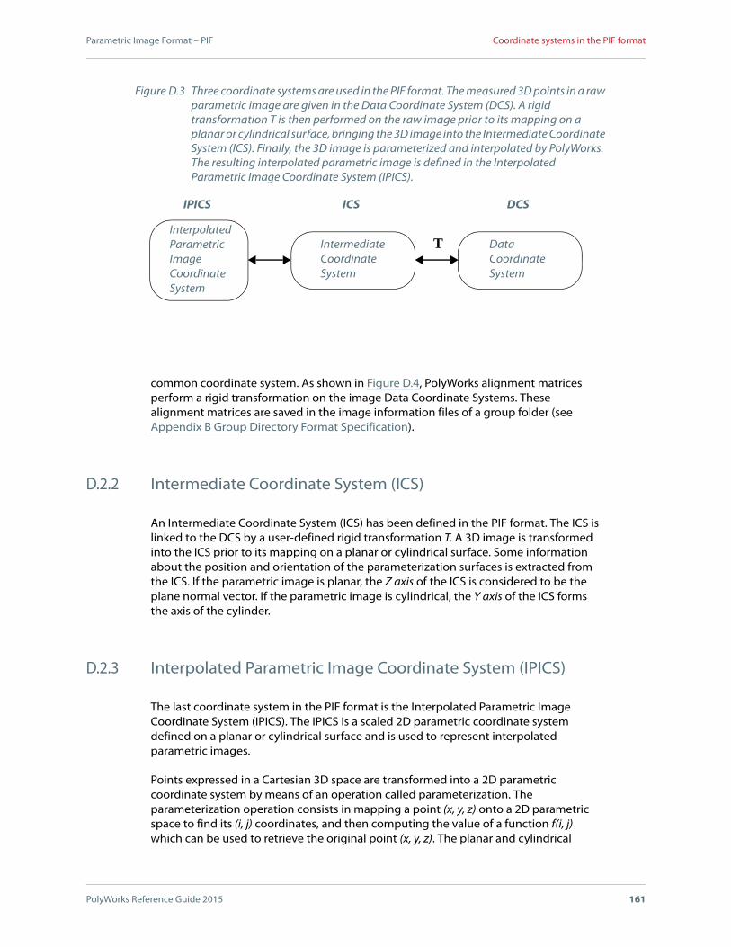
Parametric Image Format – PIF
PolyWorks Reference Guide 2015 161
Coordinate systems in the PIF format
common coordinate system. As shown in Figure D.4, PolyWorks alignment matrices perform a rigid transformation on the image Data Coordinate Systems. These alignment matrices are saved in the image information files of a group folder (see Appendix B Group Directory Format Specification).
D.2.2 Intermediate Coordinate System (ICS)
An Intermediate Coordinate System (ICS) has been defined in the PIF format. The ICS is linked to the DCS by a user-defined rigid transformation T. A 3D image is transformed into the ICS prior to its mapping on a planar or cylindrical surface. Some information about the position and orientation of the parameterization surfaces is extracted from the ICS. If the parametric image is planar, the Z axis of the ICS is considered to be the plane normal vector. If the parametric image is cylindrical, the Y axis of the ICS forms the axis of the cylinder.
D.2.3 Interpolated Parametric Image Coordinate System (IPICS)
The last coordinate system in the PIF format is the Interpolated Parametric Image Coordinate System (IPICS). The IPICS is a scaled 2D parametric coordinate system defined on a planar or cylindrical surface and is used to represent interpolated parametric images.
Points expressed in a Cartesian 3D space are transformed into a 2D parametric coordinate system by means of an operation called parameterization. The parameterization operation consists in mapping a point (x, y, z) onto a 2D parametric space to find its (i, j) coordinates, and then computing the value of a function f(i, j) which can be used to retrieve the original point (x, y, z). The planar and cylindrical
Figure D.3 Three coordinate systems are used in the PIF format. The measured 3D points in a raw parametric image are given in the Data Coordinate System (DCS). A rigid transformation T is then performed on the raw image prior to its mapping on a planar or cylindrical surface, bringing the 3D image into the Intermediate Coordinate System (ICS). Finally, the 3D image is parameterized and interpolated by PolyWorks. The resulting interpolated parametric image is defined in the Interpolated Parametric Image Coordinate System (IPICS).
TIntermediateCoordinateSystem
InterpolatedParametricImageCoordinateSystem
DataCoordinateSystem
ICSIPICS DCS

Parametric Image Format – PIF
PolyWorks Reference Guide 2015 162
Coordinate systems in the PIF format
parameterizations that are performed in the PIF format are depicted in Figure D.5. If the parametric image is planar, the i and j coordinates are respectively equal to the x and y coordinates of a point, and function f(i, j) is equal to the z coordinate. If the parametric image is cylindrical instead, then i is equal to the smallest positive angle between the (x, 0, z) vector and the Z axis, and j is equal to y. In the cylindrical case, the f(i, j) function is equal to the length of the (x, 0, z) vector.
The main purpose of the IPICS is to allow the representation of interpolated parametric images. An interpolated parametric image can be efficiently represented by a rectangular array of floating-point numbers providing values of function f. The interpolation procedure is performed once the original 3D surface mesh has been parameterized, and the (i, j) values have been scaled to ensure that the parametric distance between two consecutive horizontal or vertical neighbors in the interpolated square grid is equal to 1. The origin of the IPICS is the lower left corner of the array.
Figure D.4 This figure shows the relationship between the PIF coordinate systems and the image alignment matrices for a group a N images. The N image alignment matrices MA1, MA2, ..., MAN perform rigid transformations on the 3D images defined in their individual DCS in order to define a Common Coordinate System. These image alignment matrices are saved in the image information files of a group folder (see Appendix B Group Directory Format Specification).
Image 1
Image 2
IMAlign
Image N
ICSIPICS DCS
ICSIPICS DCS
ICSIPICS DCS
CommonCoordinateSystem
MA1
MAN
MA2
...

Parametric Image Format – PIF
PolyWorks Reference Guide 2015 163
Specifying a raw parametric image in the PIF format
D.3 Specifying a raw parametric image in the PIF format
As depicted in Figure D.2, the PIF format offers two ways to specify a raw parametric image: a) specify an array of (x, y, z) point coordinates or b) specify a polygonal mesh. It should be noted that in a cylindrical array of point coordinates, the array wraps around the cylinder axis such that the rightmost column is connected to the leftmost column. The point coordinates in a raw parametric image are given in the Data Coordinate System. The sequence of operations performed by PolyWorks on a raw parametric image is shown in Figure D.6.
A raw parametric image, defined in the DCS, is first transformed into the ICS by means of a 4x4 rigid transformation matrix. Let us assume matrix MDI having the following form:
(D-1)
A point given in the DCS is then transformed into the ICS by performing the following operation:
MDI
m1 m2 m3 m4
m5 m6 m7 m8
m9 m10 m11 m12
m13 m14 m15 m16
r1 r2 r3 tx
r4 r5 r6 ty
r7 r8 r9 tz
0 0 0 1
= =
x
y
z
j
i
x
y
z
i
j
Figure D.5 Planar (a) and cylindrical (b) parameterizations in the PIF format.
(b)(a)

Parametric Image Format – PIF
PolyWorks Reference Guide 2015 164
Specifying a raw parametric image in the PIF format
(D-2)
The parameterization operation is performed on raw images after their transformation into the ICS. Consequently, the PIF format offers the flexibility of specifying a raw image in virtually any coordinate system, as long as matrix MDI transforms the measured surface mesh into an appropriate coordinate system for parameterization. If the parametric image is planar, the parameterization is performed as follows:
(D-3)
xICS
yICS
zICS
1
MDI
xDCS
yDCS
zDCS
1
=
Figure D.6 Sequence of operations applied to a raw parametric image to generate an interpolated parametric image.
Interpolation
RawParametricImage
IntermediateCoordinateSystem
InterpolatedParametricImage
ParameterizationScaling
ICSIPICS DCS
MDI
i x=
j y=
f i j z=
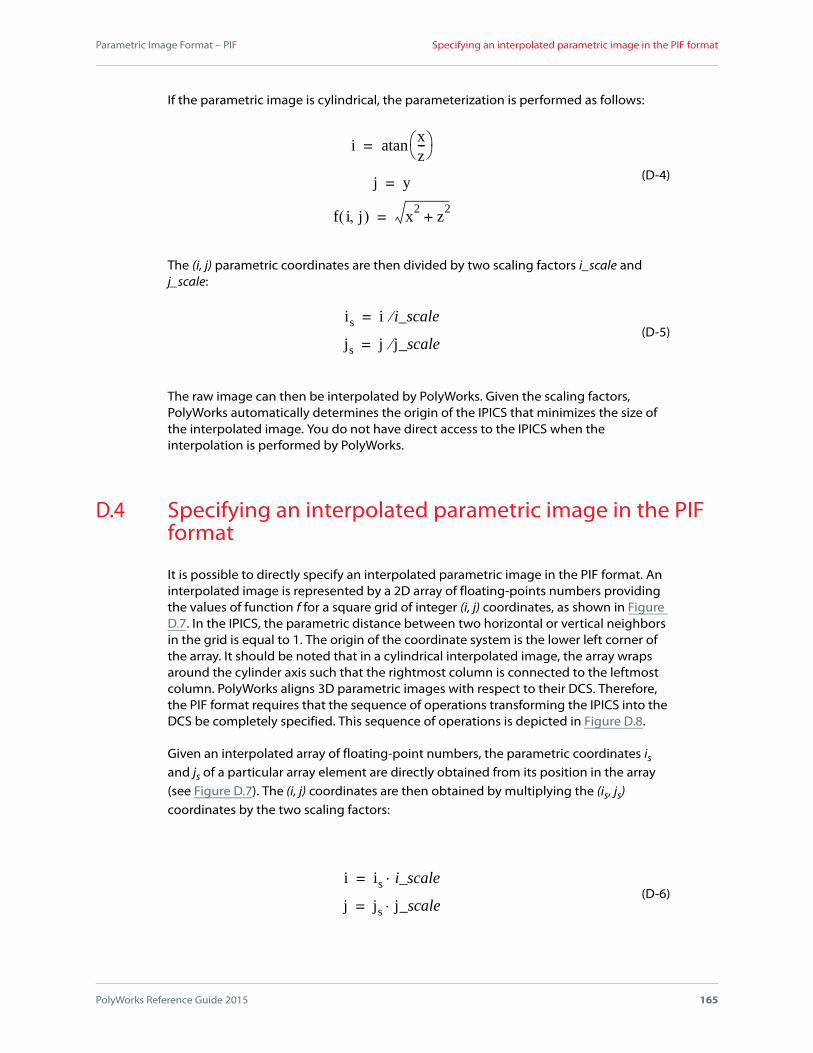
Parametric Image Format – PIF
PolyWorks Reference Guide 2015 165
Specifying an interpolated parametric image in the PIF format
If the parametric image is cylindrical, the parameterization is performed as follows:
(D-4)
The (i, j) parametric coordinates are then divided by two scaling factors i_scale and j_scale:
(D-5)
The raw image can then be interpolated by PolyWorks. Given the scaling factors, PolyWorks automatically determines the origin of the IPICS that minimizes the size of the interpolated image. You do not have direct access to the IPICS when the interpolation is performed by PolyWorks.
D.4 Specifying an interpolated parametric image in the PIF format
It is possible to directly specify an interpolated parametric image in the PIF format. An interpolated image is represented by a 2D array of floating-points numbers providing the values of function f for a square grid of integer (i, j) coordinates, as shown in Figure D.7. In the IPICS, the parametric distance between two horizontal or vertical neighbors in the grid is equal to 1. The origin of the coordinate system is the lower left corner of the array. It should be noted that in a cylindrical interpolated image, the array wraps around the cylinder axis such that the rightmost column is connected to the leftmost column. PolyWorks aligns 3D parametric images with respect to their DCS. Therefore, the PIF format requires that the sequence of operations transforming the IPICS into the DCS be completely specified. This sequence of operations is depicted in Figure D.8.
Given an interpolated array of floating-point numbers, the parametric coordinates is and js of a particular array element are directly obtained from its position in the array (see Figure D.7). The (i, j) coordinates are then obtained by multiplying the (is, js) coordinates by the two scaling factors:
(D-6)
ixz--- atan=
j y=
f i j x2
z2
+=
is i i_scale=
js j j_scale=
i is i_scale=
j js j_scale=
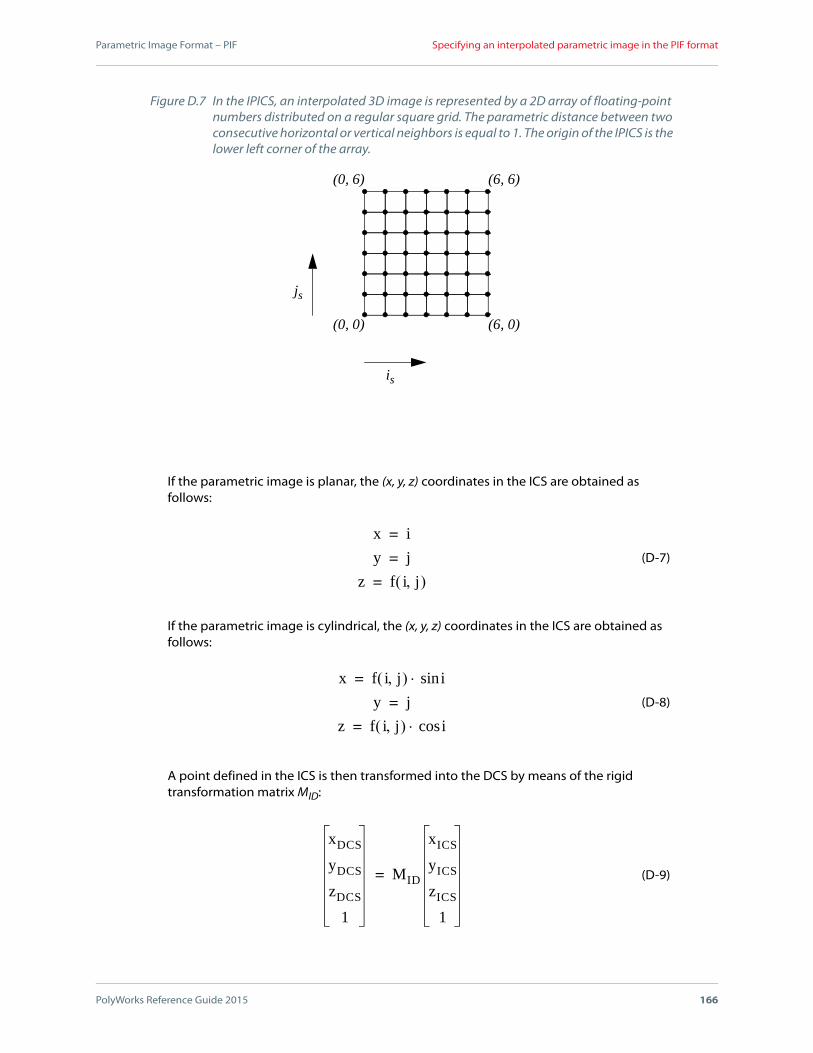
Parametric Image Format – PIF
PolyWorks Reference Guide 2015 166
Specifying an interpolated parametric image in the PIF format
If the parametric image is planar, the (x, y, z) coordinates in the ICS are obtained as follows:
(D-7)
If the parametric image is cylindrical, the (x, y, z) coordinates in the ICS are obtained as follows:
(D-8)
A point defined in the ICS is then transformed into the DCS by means of the rigid transformation matrix MID:
(D-9)
(0, 0) (6, 0)
(0, 6) (6, 6)
is
js
Figure D.7 In the IPICS, an interpolated 3D image is represented by a 2D array of floating-point numbers distributed on a regular square grid. The parametric distance between two consecutive horizontal or vertical neighbors is equal to 1. The origin of the IPICS is the lower left corner of the array.
x i=
y j=
z f i j =
x f i j isin=
y j=
z f i j icos=
xDCS
yDCS
zDCS
1
MID
xICS
yICS
zICS
1
=
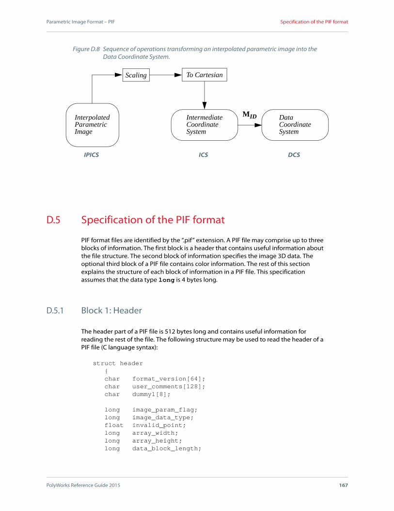
Parametric Image Format – PIF
PolyWorks Reference Guide 2015 167
Specification of the PIF format
D.5 Specification of the PIF format
PIF format files are identified by the “.pif” extension. A PIF file may comprise up to three blocks of information. The first block is a header that contains useful information about the file structure. The second block of information specifies the image 3D data. The optional third block of a PIF file contains color information. The rest of this section explains the structure of each block of information in a PIF file. This specification assumes that the data type long is 4 bytes long.
D.5.1 Block 1: Header
The header part of a PIF file is 512 bytes long and contains useful information for reading the rest of the file. The following structure may be used to read the header of a PIF file (C language syntax):
struct header{char format_version[64];char user_comments[128];char dummy1[8];
long image_param_flag;long image_data_type;float invalid_point;long array_width;long array_height;long data_block_length;
DataCoordinateSystem
IntermediateCoordinateSystem
InterpolatedParametricImage
Scaling To Cartesian
MID
Figure D.8 Sequence of operations transforming an interpolated parametric image into the Data Coordinate System.
ICSIPICS DCS
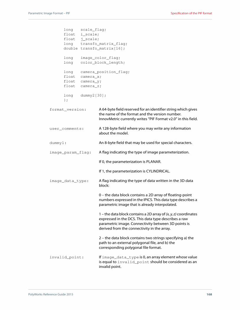
Parametric Image Format – PIF
PolyWorks Reference Guide 2015 168
Specification of the PIF format
long scale_flag;float i_scale;float j_scale;long transfo_matrix_flag;double transfo_matrix[16];
long image_color_flag;long color_block_length;
long camera_position_flag;float camera_x;float camera_y;float camera_z;
long dummy2[30];};
format_version: A 64-byte field reserved for an identifier string which gives the name of the format and the version number. InnovMetric currently writes “PIF Format v2.0” in this field.
user_comments: A 128-byte field where you may write any information about the model.
dummy1: An 8-byte field that may be used for special characters.
image_param_flag: A flag indicating the type of image parameterization.
If 0, the parameterization is PLANAR.
If 1, the parameterization is CYLINDRICAL.
image_data_type: A flag indicating the type of data written in the 3D data block:
0 – the data block contains a 2D array of floating-point numbers expressed in the IPICS. This data type describes a parametric image that is already interpolated.
1 – the data block contains a 2D array of (x, y, z) coordinates expressed in the DCS. This data type describes a raw parametric image. Connectivity between 3D points is derived from the connectivity in the array.
2 – the data block contains two strings specifying a) the path to an external polygonal file, and b) the corresponding polygonal file format.
invalid_point: If image_data_type is 0, an array element whose value is equal to invalid_point should be considered as an invalid point.

Parametric Image Format – PIF
PolyWorks Reference Guide 2015 169
Specification of the PIF format
If image_data_type is 1, a point whose z coordinate is equal to invalid_point should be considered as an invalid point.
array_width: Width of the 2D array (not used if the data is contained in an external polygonal file).
array_height: Height of the 2D array (not used if the data is contained in an external polygonal file).
data_block_length: Length in bytes of the data block.
If image_data_type is 0 or 1, the data block length is equal to the size of the 2D array in bytes.
If image_data_type is 2, data_block_length should be equal to 1024 bytes.
scale_flag: A flag related to the scaling factors:
0 – the scaling factors should not be used.
1 – the scaling factors should be used. If image_data_type is 0, the scaling factors must be specified. If image_data_type is 1 or 2, the scaling factors are optional.
i_scale: Scaling factor for the i coordinate. If the parameterization is PLANAR, i_scale is specified in image units. If the parameterization is CYLINDRICAL, i_scale is specified in degrees.
j_scale: Scaling factor for the j coordinate, specified in image units. If the parameterization is PLANAR, i_scale and j_scale should be equal.
transfo_matrix_flag:A flag indicating the transformation performed between the DCS and the ICS:
0 – the transformation matrix between the DCS and the ICS is an identity matrix. In this case, the DCS and the ICS are equivalent and the data contained in field transfo_matrix is not used.
1 – the field transfo_matrix specifies a matrix MDI that transforms points from the DCS to the ICS (see equations (D-1) and (D-2)).
2 – the field transfo_matrix specifies a matrix MID in order to transform points from the ICS to the DCS (see equation (D-9)).

Parametric Image Format – PIF
PolyWorks Reference Guide 2015 170
Specification of the PIF format
transfo_matrix: Sixteen matrix elements specified in double-precision format. The matrix elements mi are specified from left to right and from top to bottom, as in equation (D-1).
image_color_flag: A flag indicating color information. Color information is optional in a PIF file. If the image data is specified in an external polygonal file, this flag should be set to 0.
0 – there is no color information in the file.
1 – the color block specifies a gray level for each array element in the data block.
3 – the color block specifies RGB colors for each array element in the data block.
4 – the color block specifies RGBA colors for each array element in the data block.
color_block_length: Length in bytes of the color block.
camera_position_flag:A flag related to the (x, y, z) position of the 3D digitizer in the DCS:
0 – no camera position is specified.
1 – a camera position is specified by camera_x, camera_y, camera_z.
camera_x: x position of the 3D digitizer in the DCS.
camera_y: y position of the 3D digitizer in the DCS.
camera_z: z position of the 3D digitizer in the DCS.
dummy2: Reserved for future use.
D.5.2 Block 2: 3D Data
This block contains data_block_length bytes of information.
If image_data_type is set to 0, the data block contains a 2D array of single-precision floating-point numbers expressed in the IPICS. This data type is used to describe an interpolated parametric image. The width and height of the array are respectively equal to array_width and array_height. The array elements are written from left to right and from bottom to top. The following is the order in which the elements of a 6x4 array would be written:
18 19 20 21 22 2312 13 14 15 16 17
Parametric Image Format – PIF
PolyWorks Reference Guide 2015 171
Specification of the PIF format
6 7 8 9 10 110 1 2 3 4 5
The figure represents the offset of each array element in the data block.
If image_data_type is set to 1, the data block contains a 2D array of (x, y, z) coordinates expressed in the DCS. This data type describes a raw parametric image. Each array element consists of three single-precision floating-point numbers, specifying respectively the x, y and z coordinates of a measured 3D point. The array elements are written from left to right and from bottom to top.
If image_data_type is set to 2, the data block contains two strings. The first string specifies the path to an external polygonal file describing the surface of the 3D image. The second string specifies the corresponding polygonal file format. A block of 512 bytes should be allocated for each string. Both strings must be written at the beginning of their block and terminated by a null character. The rest of the blocks may be filled with any characters.
D.5.3 Block 3: Optional color information
This optional block contains color_block_length bytes of information. The contents of the block depend on the value of image_color_flag. If this flag is set to 0, the color block is empty.
If image_color_flag is set to 1, the block contains a 2D array that has the same width and height as the data block array. Each array element is then 1 byte long and specifies the gray level of the corresponding vertex in the data block array.
If image_color_flag is set to 3, the block contains a 2D array that has the same width and height as the data block array. Each array element is then 3 bytes long and specifies respectively the R, G, and B color components of the corresponding vertex in the data block array.
If image_color_flag is set to 4, the block contains a 2D array that has the same width and height as the data block array. Each array element is then 4 bytes long and specifies respectively the R, G, B, and A color components of the corresponding vertex in the data block array.

E
App
endi
x
PolyWorks Reference Guide 2015 172
Utility Programs
This appendix presents various utility programs that are run from a command line.

Utility Programs
PolyWorks Reference Guide 2015 173
Introducing the utilities
E.1 Introducing the utilities
The table that follows lists the utility programs in alphabetical order, describes each one briefly, and provides a link to the related subsection where complete information is provided.
Utility Description Reference
Ac2grpTakes a folder containing a set of AC files and creates an IMAlign group foldera.
Section E.2 Ac2grp
Bre2grpTakes a folder containing a set of BRE files and creates an IMAlign group foldera.
Section E.3 Bre2grp
Cyl2imConverts a Cyberware cylindrical scan in Echo format to a polygonal model file and a set of rectangular PIF images.
Section E.4 Cyl2im
Cyra2pifTakes a file containing a set of Cyra scans and creates a set of PIF files that can be imported into PolyWorks.
Section E.5 Cyra2pif
Echo_rings
Takes one or several scan rings, computes the image alignment transformation matrices using the turntable rotation angles and scanner vertical positions, and creates an IMAlign group foldera.
Section E.6 Echo_rings
Grp2ac, Grp2bre, and
Grp2surf
Take an IMAlign group foldera and generates new AC, BRE, or SURF files in which the 3D data is expressed using the unique coordinate system computed by IMAlign.
Section E.7 Grp2ac, Grp2bre, and Grp2surfs
Mgf_ringsTakes one of a set of MGF ring scans and creates an IMAlign group foldera.
Section E.8 Mgf_rings
Net2pifProvides the automatic translation of a set of NET files located in a given folder into a corresponding set of PIF files.
Section E.9 Net2pif
Pif2grpTakes a folder containing a set of PIF files and creates an IMAlign group foldera.
Section E.10 Pif2grp
Ply_ringsAutomatically creates an IMAlign group foldera from a set of four Ply scans acquired by the Whole Body scanner.
Section E.11 Ply_rings
Surf2grpTakes a folder containing a set of SURF files and creates an IMAlign group foldera.
Section E.12 Surf2grp
TopifConverts polygonal files, ASCII grids of points, and unorganized ASCII point clouds to the PIF format.
Section E.13 Topif
Vox2grpTranslates the color 3D data produced by the Voxelan 3D digitizer into an IMAlign group folder.
Section E.14 Vox2grp

Utility Programs
PolyWorks Reference Guide 2015 174
Introducing the utilities
Vvd_ringsTakes one of a set of Vivid ring scans and creates an IMAlign group foldera.
Section E.15 Vvd_rings
Ww2pifTakes a TFM file and translates its contents to a set of PIF files.
Section E.16 Ww2pif
Xyz2grpTakes a folder containing a set of XYZ files and creates an IMAlign group foldera.
Section E.17 Xyz2grp
a. Prior to V9, IMAlign projects were saved to group directories. Starting in V9,IMAlign projects created using IMAlign are saved to a workspace. Theimported point clouds are also managed within the workspace. ThePolyWorks Workspace Manager allows creating IMAlign projects fromgroup directories by reading the .info file, and also allows exporting IMAlignprojects within workspaces to group directories.
Utility Description Reference

Utility Programs
PolyWorks Reference Guide 2015 175
Ac2grp
E.2 Ac2grp
The 3D data measured by Steinbichler’s 3D digitizers is written using the AC file format. Files written using the AC format may have the .ac or the .AC extension. These AC files may contain an approximate alignment transformation matrix that can be used by IMAlign as a startup point for the alignment process. The Ac2grp utility takes a folder containing a set of AC files and creates an IMAlign group folder.
A general call to Ac2grp has the following format:
ac2grp input_folder
-grp group_folder
[-lock]
[-verbose]
where,
input_folder specifies the path to a folder containing AC files.
-grp specifies the path to the output group folder generated by Ac2grp.
-lock is an optional parameter that locks the alignment of the AC files. This parameter should only be used when the alignment transformation matrices provided by the AC files are very accurate. IMAlign can import two AC directories and align the two corresponding sets of 3D images while preserving the relative alignment of the images within a folder.
The -verbose parameter can be used to obtain additional information during the execution of Ac2grp.
Utility Programs
PolyWorks Reference Guide 2015 176
Bre2grp
E.3 Bre2grp
The 3D data measured by Breuckmann’s 3D digitizers can be written using the BRE file format. Files written using the BRE format may have the .bre or the .BRE extension. The Bre2grp utility takes a folder containing a set of BRE files and creates an IMAlign group folder. A general call to Bre2grp has the following format:
bre2grp input_folder
-grp group_folder
[-verbose]
where,
input_folder specifies the path to a folder containing BRE files.
-grp specifies the path to the output group folder generated by Bre2grp.
The -verbose parameter can be used to obtain additional information during the execution of Bre2grp.

Utility Programs
PolyWorks Reference Guide 2015 177
Cyl2im
E.4 Cyl2im
The Cyl2im program converts a Cyberware cylindrical scan in Echo format, which can be partial or complete, to a polygonal model file and a set of rectangular PIF images. The PIF images may then be loaded into PolyWorks for further processing.
A general call to Cyl2im has the following format:
cyl2im input_file
-o output_folder
-nb nb_PIF_images
-fmt polygonal_format
[-maxangle value]
[-step value]
[-verbose]
where,
input_file specifies the path to a Cyberware cylindrical scan in Echo format.
-o specifies the path to an output folder where all PIF files will be generated.
-nb specifies the number of rectangular PIF images describing the cylindrical scan surface. The images are generated at different viewing angles in order to describe the entire cylindrical scan’s surface.
-fmt specifies the polygonal format in which the output polygonal model file will be written.
-maxangle optionally specifies a maximum angle between a triangle and the cylinder’s normal vector. The default is 75 degrees.
-step optionally specifies an interpolation step for the PIF images. By default, the value of LTINCR in the Echo file is used.
The -verbose parameter can be used to obtain additional information during the execution of Cyl2im.

Utility Programs
PolyWorks Reference Guide 2015 178
Cyra2pif
E.5 Cyra2pif
A set of 3D scans measured by a Cyra 3D digitizer can be written to a single file using the Cyra ASCII file format. Files written using the Cyra ASCII file format must have the .pts or the .ptx extension. The Cyra2pif utility takes a file containing a set of Cyra scans and creates a set of PIF files that can be imported into PolyWorks.
A general call to Cyra2pif has the following format:
cyra2pif input_file
-o output_folder
-invert
[-step value]
[-verbose]
where,
input_file specifies the path to a Cyra .pts or .ptx file.
-o specifies the path to an output folder where the PIF files will be generated.
-invert specifies that the orientation of the surface should be inverted. The PTX format has been altered by recent versions of the Cyra software. The -invert flag may be required to correctly process newer PTX files.
-step specifies an interpolation step for all PIF files.
The -verbose parameter can be used to obtain additional information during the execution of Cyra2pif.
Utility Programs
PolyWorks Reference Guide 2015 179
Echo_rings
E.6 Echo_rings
A ring of Echo scans consists of a set of Cyberware scans acquired at different viewing angles by rotating the measured object using a turntable. Each scan file must have the same generic file name and a three-digit integer suffix specifying the rotation angle in degrees.
Example: The six files eleph000, eleph060, eleph120, eleph180, eleph240, and eleph300 would represent a 6-scan ring acquired at 60-degree intervals.
The operation for importing Echo Rings provided by IMAlign invokes an external Echo_rings program to automatically load a scan ring into IMAlign. The Echo_rings program takes one or several scan rings, computes the image alignment transformation matrices using the turntable rotation angles and scanner vertical positions, and creates an IMAlign group folder.
A general call to Echo_rings has the following format:
echo_rings input_scan_file1 ...
-vpos vertical_position1 ...
-hoff horizontal_offset
-grp group_folder
[-verbose]
where,
input_scan_file1 specifies the path to one scan file, identifying a particular scan ring. Several scan files may be specified in one command line.
-vpos specifies, for each input ring, the vertical position of the scanner in millimeters. If a single ring is being processed, a 0.0 value may be passed to -vpos.
-hoff specifies an horizontal offset value used to compute the rotational center of the turntable. In the current generation of Cyberware scanners, a 0.0 value should be used. In some older scanners, a value of -3.5 might yield alignment transformation matrices that are more accurate.
-grp specifies the path to the output group folder generated by Echo_rings.
The -verbose parameter can be used to obtain additional information during the execution of Echo_rings.

Utility Programs
PolyWorks Reference Guide 2015 180
Grp2ac, Grp2bre, and Grp2surfs
E.7 Grp2ac, Grp2bre, and Grp2surfs
The alignment results produced by IMAlign are saved in a group folder. A group folder contains the absolute path to all aligned 3D image files as well as their alignment transformation matrices. The Grp2ac, Grp2bre, and Grp2surf utilities take an IMAlign group folder and generates new AC, BRE, or SURF files in which the 3D data is expressed using the unique coordinate system computed by IMAlign.
A general call to one of the Grp2xxx programs has the following format:
grp2xxx input_group_folder
[-o output_folder]
[-name generic_name]
[-ni] [-verbose]
where,
grp2xxx represents the program’s name, where xxx can be set to ac, bre, or surf.
input_group_folder specifies the path to the input IMAlign group folder.
The -o parameter may be used to specify the output folder for the new AC, BRE, or SURF files. By default, the program creates a new_ac, new_bre, or new_surf folder within the input group folder and puts the newly created 3D images files in this new folder.
By default, the new AC, BRE, or SURF files will have the same name as the original ones. This behavior may be modified by specifying a generic name using the -name parameter. Special keywords are provided for specifying generic names. IMG is a variable that specifies the file name of the original 3D image. To construct the output file name from the original file name, type ${IMG}, which represents the value of the IMG variable. Two modifiers allow the modification of this variable. Modifier :r removes the extension of the file name, while modifier :e removes everything but the extension. The modifiers should follow the IMG string and be enclosed within the braces. The string %d may also be used in a generic file name. It represents an integer number indicating the image index in the group folder.
Since a Grp2xxx program is usually invoked within a Command Window, generic names should be enclosed in a pair of double-quotes to prevent variable substitution:
-name “${IMG}” specifies the original file names
-name “im%d.xxx” specifies im0.xxx, im1.xxx, im2.xxx, and so on.
By default, a Grp2xxx program checks if existing files might be overwritten by the creation of the new 3D image files and asks for user confirmation if necessary. The -ni parameter means ‘no interaction’ and may be used to bypass this verification.

Utility Programs
PolyWorks Reference Guide 2015 181
Grp2ac, Grp2bre, and Grp2surfs
The -verbose parameter can be used to obtain additional information during the execution of the program.

Utility Programs
PolyWorks Reference Guide 2015 182
Mgf_rings
E.8 Mgf_rings
A ring of MGF scans consists of a set of Voxelan’s MGF scans acquired at different viewing angles by rotating the measured object using a turntable. Each scan file name must consist of three parts: a generic prefix common to the scans, a 3-digit integer specifying the rotation angle in degrees, and an .mgf or .MGF extension.
Example: The four files eleph000.mgf, eleph090.mgf, eleph180.mgf, and eleph270.mgf would represent a 4-scan ring acquired at 90-degree intervals.
The Mgf_rings program takes one of the ring scans, and creates an IMAlign group folder.
A general call to Mgf_rings has the following format:
mgf_rings input_scan_file
-grp group_folder
[-verbose]
where,
input_scan_file specifies the path to one scan file in the ring.
-grp specifies the path to the output group folder generated by Mgf_rings.
The -verbose parameter can be used to obtain additional information during the execution of Mgf_rings.

Utility Programs
PolyWorks Reference Guide 2015 183
Net2pif
E.9 Net2pif
The 3D data measured by Inspeck’s 3D digitizers can be written using the NET format. Files written using the NET format may have the .net or the .NET extension. The Net2pif program has been devised for the automatic translation of a set of NET files located in a given folder into a corresponding set of PIF files.
A general call to Net2pif has the following format:
net2pif input_folder
[-step step_value]
[-verbose]
where,
input_folder specifies the path to a folder containing NET files. Net2pif creates the output PIF files in the same folder. As a result, you must have read/write permission for the input folder.
-step specifies an interpolation step for the NET files.
The -verbose parameter can be used to obtain additional information during the execution of Net2pif.

Utility Programs
PolyWorks Reference Guide 2015 184
Pif2grp
E.10 Pif2grp
The Pif2grp utility takes a folder containing a set of PIF files and creates an IMAlign group folder.
A general call to Pif2grp has the following format:
pif2grp input_folder
-grp group_folder
[-verbose]
where,
input_folder specifies the path to a folder containing PIF files.
-grp specifies the path to the output group folder generated by Pif2grp.
The -verbose parameter can be used to obtain additional information during the execution of Pif2grp.

Utility Programs
PolyWorks Reference Guide 2015 185
Ply_rings
E.11 Ply_rings
The Ply_rings program has been devised for automatically creating an IMAlign group folder from a set of four Ply scans acquired by the Whole Body scanner. Each scan file name must consist of three parts: a generic prefix common to the four scans, a three-digit integer specifying the rotation angle in degrees, and a .ply extension.
Example: The four files Paul000.ply, Paul075.ply, Paul180.ply, and Paul255.ply would represent the four Whole Body scans of Paul.
The Ply_rings program takes one of the Ply scans, computes the image alignment transformation matrices using the rotation angles, and creates an IMAlign group folder.
A general call to Ply_rings has the following format:
ply_rings input_scan_file
-grp group_folder
[-verbose]
where,
input_scan_file specifies the path to one scan file.
-grp specifies the path to the output group folder generated by Ply_rings.
The -verbose parameter can be used to obtain additional information during the execution of Ply_rings.

Utility Programs
PolyWorks Reference Guide 2015 186
Surf2grp
E.12 Surf2grp
The 3D data measured by ATOS 3D digitizers can be written using the SURF file format. The Surf2grp utility takes a folder containing a set of SURF files and creates an IMAlign group folder.
A general call to Surf2grp has the following format:
surf2grp input_folder
-grp group_folder
[-verbose]
where,
input_folder specifies the path to a folder containing SURF files.
-grp specifies the path to the output group folder generated by Surf2grp.
The -verbose parameter can be used to obtain additional information during the execution of Surf2grp.

Utility Programs
PolyWorks Reference Guide 2015 187
Topif
E.13 Topif
The Topif utility has been designed to convert polygonal files, ASCII grids of points, and unorganized ASCII point clouds to the PIF format.
A general call to Topif has the following format:
topif input_folder
-o output_folder
-poly
-ext file_name_extension
[-fmt polygonal_format]
[-invert]
[-step step_value]
[-maxedge edge_length]
[-verbose]
topif input_folder
-o output_folder
-grid
-ext file_name_extension
[-fmt polygonal_format]
[-invert]
[-step step_value]
[-maxedge edge_length]
[-verbose]
topif input_folder
-o output_folder
-triangulate

Utility Programs
PolyWorks Reference Guide 2015 188
Topif
-ext file_name_extension
[-fmt polygonal_format]
[-invert]
[-step step_value]
[-maxedge edge_length]
[-verbose]
where,
Topif can be invoked using either the -poly, -grid, or -triangulate parameter. The -poly parameter specifies a conversion from polygonal files to PIF files. The -grid parameter specifies a conversion from ASCII grids of points to PIF files. Finally, the -triangulate parameter specifies a conversion from unorganized ASCII point clouds to PIF files.
For all three modes, the input files must describe a digitized surface that can be projected onto the X-Y plane. By default, the surface normals must point in the general direction of the positive Z axis. If they point in the direction of the negative Z axis, the -invert parameter should be used.
When the -poly parameter is used, the digitized surface is described by an existing polygonal model. Topif then only creates a PIF file that refers to the polygonal model. When the -grid parameter is used, the digitized surface consists of an ASCII grid of points in which points are distributed on a regular square grid on the X-Y plane. Topif automatically connects the 3D points using the points (x, y) values and saves a surface mesh to a PIF file. Finally, the -triangulate parameter can be used to automatically triangulate an unorganized ASCII point cloud. Topif will then create two files per input file. One will contain the polygonal surface, while a PIF file will be created to refer to this polygonal model.
input_folder specifies the path to a folder containing the input files.
-o specifies the path to the output folder where the PIF files will be created.
-ext specifies the extension of the input files (i.e., the set of characters following the last dot in a file name). Files with no extensions cannot be processed by Topif.
When the -poly parameter is used, the polygonal format can be explicitly specified using the -fmt parameter. This option is useful when the file name extension does not match the format name.
The -invert parameter must be used when the digitized surface points in the general direction of the negative Z axis.
The -step parameter specifies an interpolation step for the generated PIF files. The option is not necessary for ASCII grids of points (-grid), as Topif automatically computes the step when reading the grid.

Utility Programs
PolyWorks Reference Guide 2015 189
Topif
The -maxedge parameter specifies the maximum 3D length of a triangle edge and is used when unorganized ASCII point clouds are triangulated with the -triangulat parameter. Any triangle having an edge whose length is larger than -maxedge is removed from the point cloud triangulation.
The -verbose parameter can be used to obtain additional information during the execution of Topif.

Utility Programs
PolyWorks Reference Guide 2015 190
Vox2grp
E.14 Vox2grp
The Voxelan 3D digitizer saves its output 3D data under the form of a depth file that contains the geometric measurements, and eight .rgb files that contain the associated color data. The Vox2grp program translates the color 3D data produced by the Voxelan 3D digitizer into an IMAlign group folder.
A general call to Vox2grp has the following format:
vox2grp input_folder
[-step step_value]
[-verbose]
where,
input_folder specifies the path to a folder containing the depth and color files. Vox2grp creates the IMAlign group folder in the same folder. As a result, you must have read/write permission for the input folder.
-step specifies an interpolation step for the Voxelan data. A default value of 1.0 is used if no step is specified.
The -verbose parameter can be used to obtain additional information during the execution of Vox2grp.

Utility Programs
PolyWorks Reference Guide 2015 191
Vvd_rings
E.15 Vvd_rings
A ring of Vivid scans consists of a set of Minolta’s Vivid scans acquired at different viewing angles by rotating the measured object using the turntable. Each scan file name must consist of three parts: a generic prefix common to the scans, an integer specifying the rotation angle in degrees, and a .vvd or .VVD extension.
Example: The six files eleph0.vvd, eleph60.vvd, eleph120.vvd, eleph180.vvd, eleph240.vvd, and eleph300.vvd would represent a 6-scan ring acquired at 60-degree intervals.
The Vvd_rings program takes one of the ring scans, and creates an IMAlign group folder.
A general call to Vvd_rings has the following format:
vvd_rings input_scan_file
-grp group_folder
[-verbose]
where,
input_scan_file specifies the path to one scan file in the ring.
-grp specifies the path to the output group folder generated by Vvd_rings.
The -verbose parameter can be used to obtain additional information during the execution of Vvd_rings.

Utility Programs
PolyWorks Reference Guide 2015 192
Ww2pif
E.16 Ww2pif
The 3D data measured by a Wicks&Wilson 3D digitizer is written in a TFM file. Files written using the TFM format may have the .tfm or the .TFM extension. The Ww2pif utility takes a TFM file and translates its contents to a set of PIF files. The PIF files may then be imported into PolyWorks for further processing.
A general call to Ww2pif has the following format:
ww2pif input_file
-o output_folder
-step value
[-verbose]
where,
input_folder specifies the path to a TFM file.
-o specifies the path to the output folder where all PIF files will be generated.
The -step parameter specifies an interpolation step for the generated PIF files. A value of 2.0 millimeters is recommended for body scans.
The -verbose parameter can be used to obtain additional information during the execution of Ww2pif.

Utility Programs
PolyWorks Reference Guide 2015 193
Xyz2grp
E.17 Xyz2grp
The 3D data measured by EOIS’ 3D digitizers can be written using the XYZ file format. Files written using the XYZ format may have the .xyz or the .XYZ extension. The Xyz2grp utility takes a folder containing a set of XYZ files and creates an IMAlign group folder.
A general call to Xyz2grp has the following format:
xyz2grp input_folder
-grp group_folder
[-verbose]
where,
input_folder specifies the path to a folder containing XYZ files.
-grp specifies the path to the output group folder generated by Xyz2grp.
The -verbose parameter can be used to obtain additional information during the execution of Xyz2grp.

PolyWorks Reference Guide 2015 194
AASCII point clouds
exporting 123importing 119
ATOS 180, 186
BBreuckmann 176, 180browsers
configuring startup directory 134
Ccharacter set 78color of interface items, editing 133colors
configuring interface colors 133contextual help 86conventions, command-line use 23Cyberware 177, 179, 185cylindrical scans 177Cyra 178
EEOIS 193
FFLEXnet 135, 136FLEXnet Licensing 135, 136
Ggetting help 84
GOM 180, 186group directory format 146
Hhelp
complete reference information 84contextual 86getting 84
IIMAlign, starting 66IMEdit, starting 66IMInspect Probing, starting 66IMInspect, starting 66importing
polygonal files 44, 45IMSurvey, starting 66Inspeck 183installing PolyWorks 135
J-Llanguage preferences 78License, FLEXnet 135, 136line format, text templates 121
MMacro Script Editor 89material, editing 128Minolta 191
Index

Index
PolyWorks Reference Guide 2015 195
Oobjects
importing from IMInspect projects 46OpenGL font 79opening
a polygonal model file 44, 45
PPIF
conflict with Windows extension 88converting a polygonal file to PIF 187converting an ASCII grid of points to PIF 187creating a group directory 184public 3D image format 158
POL, public polygonal format 150polygonal files, importing 44, 45PolyWorks
configuring translators 80list of manuals 20process 16using the Workspace Manager 28
Rrotating
about the X axis 125about the Y axis 125
rotating objects in the 3D scene 127
SSteinbichler 175, 180
Ttab interface 26terminology, interface
check box 24list box 25option button 24tab interface 26text box 25
text file templates 119user-defined 121
text filesexporting 123
importing 119translating
along the X axis 126along the Y axis 126along the Z axis 126
translators, configuring 80
V-ZViewer, starting 66visual layouts
exporting 95loading 96macro scripts
importing from visual layouts 97macro scripts in 97opening a backup 97system provided 76, 95
Voxelan 182, 190Wicks&Wilson 192zooming in the 3D scene 127
Related Documents