POLITECNICO DI TORINO Department of Environment, Land and Infrastructure Engineering Master of Science in Petroleum Engineering Master Thesis Project ANALYSING OF ABNORMAL ANNULAR PRESSURE AND APPLICATION OF MITIGATATION TECHNOLOGIES TO PROTECT WELL INTEGRITY Supervisor professor Raffaele Romagnoli Author Al-Inizi Raed AbdulRaheem (S264263) Torino November 2020 A thesis submitted in compliance with the requirements for the Master of Science degree in petroleum engineering

Welcome message from author
This document is posted to help you gain knowledge. Please leave a comment to let me know what you think about it! Share it to your friends and learn new things together.
Transcript
POLITECNICO DI TORINO
Department of Environment, Land and Infrastructure Engineering Master of Science in Petroleum Engineering
Master Thesis Project
ANALYSING OF ABNORMAL ANNULAR PRESSURE AND
APPLICATION OF MITIGATATION TECHNOLOGIES TO
PROTECT WELL INTEGRITY
Supervisor
professor Raffaele Romagnoli
Author
Al-Inizi Raed AbdulRaheem
(S264263)
Torino November 2020 A thesis submitted in compliance with the requirements
for the Master of Science degree in petroleum engineering

ii
“Esiste nella vita una sola felicità: amare e essere amati. George Sand”

iii
DECLARATION
I announce that this work that I have given to you is of my sincere work and
commitment. It is delivered under the requirements of the Master of Science degree
in Petroleum Engineering at Politecnico di Torino, Italy. And in no other university
was it offered for any academic degree or examination.
iv
DEDICATION AND ACKNOWLEDGEMENTS
Acknowledgments first and foremost
Thanks to Politecnico Di Torino for being one of its Alumni. This university gave me
contact with great people and friends from around the world. Furthermore, a great
experience with the educational staff in the department of environment, land, and
infrastructure engineering (DIATI).
Thanks to Professor RAFFAELE ROMAGNOLI for his advice, help, and support
throughout the project work.
Thanks to Professor Andrea Carpignano for his advice on the risk analysis part of
my work.
I devote this research to my dear father because he has the first credit in my life for
reaching what I have reached now. I also dedicate this work to my mother “Fathiyya”
and my wife for their continuous supporting, praying, and standing with me
throughout my studies.
Lastly, many thanks and appreciation to my company ‘Iraqi Ministry of Oil / Basra
Oil Company’ and scholarship sponsor ‘Eni’ who trust in me and provide me this
inconceivable chance to study at an important university like Politecnico di Torino
and develop a project like this one.

v
ABSTRACT
During casing design operations there are product spaces generated between casings strings or between tubing and casing that are called annuli, it is the product as a result of design and not created purposely. The ideal case is these annuli must be filled with cement, but for some reasons such as limited cement technologies and weak formations, these annuli are filled with small-compressibility fluids (generally weighted mud, cement spacers, or transparent brines) to avoid fracturing of the weak formation and lost circulation during cementation. In high-pressure high-temperature wells (HPHT) these fluids will be heated during drilling operations and production activities by the fluids that coming from heat formations in the bottom of the well and as a result, it will expand and if the annulus was closed it will generate a trapped annulus pressure (TAP), it is the first type of annular pressure, this pressure can reach a very high value (10,000 - 12,000 psi or more). This pressure is more problematic in subsea wells (SSW) where the wellhead of SSW doesn’t permit annulus venting except for annulus ‘A’ (production casing - tubing). The second type of annular pressure is sustain casing/annular pressure (SC/AP), that caused by the failure of internal or external barriers of well integrity, involving casing and cement, in some cases when the annulus fluid pressurized by formation fluids invasion due to pressure difference between formation and annulus and there is a passageway through microfractures and channels in poor cement where there is a failure in the external barrier of well integrity, or it can be generated mechanically by tubing leak inside annulus or linking between annuli due to seals or casings damage, where there is an internal integrity barrier failure. Both of these two types of annular pressure are harmful when becoming abnormal annular pressure. Abnormal annular pressure is one of the most important issues that threaten the casing of wells from the annulus and may result in a casing failure. Because the casing is the major part of a well integrity system, so annular pressure impacts the well barriers and may lead to damage of the well integrity. Analysing the annular pressure by the source of this pressure, type, possible location, causes of generation, and calculation of permissible and present limits are more important during well design. The last conventional casing design for deep-water HPHT and SSW shows insufficient control of abnormal annular pressure and safety of well integrity by recording some accidents in most of the deep-water wells in the Gulf of Mexico (GOM) and other locations of the same problems. So, it is obligate to account for annular pressure in the new unconventional design that is provided in this research based on mitigating the effect of abnormal annular pressure and provide a complete risk plan to provide a robust design. We consider the annular pressure, apply risk analysis and define permissible limits to show the possible impaction to the well integrity, that study the case by identifying the possible risk, evaluate the risk level and probability of failure, then provide the ways to mitigate this risk to protect the well integrity barrier with applying risk treatment to the most critical (unacceptable) risk levels. Also, we apply an optimization strategy for mitigation devices selection for TAP and optimization for the new design and possible remediation for SCP. Furthermore, there is another type of annular pressure it can be the third type, called applied pressure, that generated intentionally by the operator in a specific value, such as gas lifting and injection wells, this type has a control risk because it programmed based on annulus properties and consideration of its effect on surrounding annuli. In this research we focal on the first two types of annular pressure for development, analysis, calculation, and application in new well design.
vi
LIST OF CONTENTS DECLARATION ...............................................................................................................III
DEDICATION AND ACKNOWLEDGEMENTS ......................................................... IV
ABSTRACT ........................................................................................................................ V
LIST OF CONTENTS....................................................................................................... VI LIST OF FIGURES ........................................................................................................... IX
LIST OF TABLES ............................................................................................................. XI
NOMENCLATURE ........................................................................................................ XII
INTRODUCTION ............................................................................................................... 1
CHAPTER ONE .................................................................................................................. 3 ANALYSING OF ANNULAR PRESSURE ...................................................................... 3
1.1 TUBULAR ANNULUS ...................................................................................................... 3 1.2 TYPES OF ANNULI ......................................................................................................... 3 1.3 TYPES OF TRAPPING WAYS IN THE ANNULI .................................................................... 3 1.4 ANNULAR PRESSURE ..................................................................................................... 5 1.5 TYPES OF ANNULAR PRESSURE ...................................................................................... 5
1.5.1 Thermal pressure .................................................................................................. 5 1.5.1.1 Feature that characterizes thermal pressure loads ......................................... 5 1.5.1.2 Factors affecting thermal pressure ................................................................. 6 1.5.1.3 Behaviours and evaluations of thermal pressure in the annulus .................... 8 1.5.1.4 Modelling and calculation of TAP for Multiple Annuli ................................ 9 1.5.1.5 Phases of TAP occurrence ........................................................................... 14 1.5.1.6 Possible cases and locations of trapped annuli ............................................ 16
1.5.2 Sustained casing/annular pressure SCP or SAP ................................................. 18 1.5.2.1 Causes of SCP ............................................................................................. 18
1.5.2.1.1 SCP by internal integrity failure ........................................................... 19 1.5.2.1.2 SCP by external integrity failure .......................................................... 19
1.5.2.2 Modelling of SCP ........................................................................................ 20 1.5.3 Applied Pressure (AP) ........................................................................................ 22
CHAPTER TWO ............................................................................................................... 23
DESIGNING OF ANNULAR PRESSURE MITIGATION TECHNIQUES .............. 23
2.1 MITIGATION OF TAP .................................................................................................. 23 2.2 FUNCTION OF TAP MITIGATION DEVICE...................................................................... 23 2.3 DESIGN PROCEDURE FOR TAP MITIGATION ................................................................ 23 2.4 COMMON TECHNIQUES FOR APB MITIGATION............................................................ 25
2.4.1 Active mitigation methods.................................................................................. 25 2.4.1.1 Cementing to surface ................................................................................... 25 2.4.1.2 Thermal-isolated Pipes (Vacuum Insulated Tubing VIT) ........................... 27 2.4.1.3 Thermal isolating packer fluid (IPF) ........................................................... 29 2.4.1.4 Decrease production rate ............................................................................. 30
2.4.2 Passive mitigation methods ................................................................................ 31 2.4.2.1 Cement shortfall .......................................................................................... 32
2.4.2.1.1 Application of cement shortfall (Open shoe) technique ....................... 32 2.4.2.2 Using high compressibility fluid ................................................................. 33
vii
2.4.2.2.1 Nitrified Spacers ................................................................................... 33 2.4.2.2.2 Water-Based Spacer (Fluid That Shrinks) ............................................ 36 2.4.2.2.3 Drilling fluids Spacer............................................................................ 36
2.4.2.3 Pressure relief device ................................................................................... 36 2.4.2.3.1 Valves to the atmosphere ...................................................................... 36 2.4.2.3.2 Hole at the wellhead with an ROV ....................................................... 37 2.4.2.3.3 Rupture disk technique ......................................................................... 37 2.4.2.3.4 Casing perforation ................................................................................ 40 2.4.2.3.5 Relief collar for annular pressure ......................................................... 40
2.4.2.4 Mitigation by using syntactic foam (Hollow glass) ..................................... 41 2.4.2.5 Heavyweight/high yield casing (Improve structural strength) .................... 42 2.4.2.6 Mitigation casing ......................................................................................... 43 2.4.2.7 Additional chamber ..................................................................................... 44 2.4.2.8 Sacrificial casing.......................................................................................... 45
2.4.3 Summary of TAP mitigation devices ................................................................. 45 2.5 MITIGATION TECHNIQUES FOR SCP ............................................................................ 51
2.5.1 Mitigation through well design........................................................................... 51 2.5.2 Mitigation by foamed spacer technology ........................................................... 51 2.5.3 Mitigation by applying cement pulsation method .............................................. 52
2.6 REVIEW OF REMEDIATION METHODS OF SCP .............................................................. 53
CHAPTER THREE ........................................................................................................... 55
RISK ANALYSIS OF ABNORMAL ANNULAR PRESSURE .................................... 55 3.1 WELL INTEGRITY ........................................................................................................ 55 3.2 ANNULUS INTEGRITY .................................................................................................. 55 3.3 RISK MANAGEMENT .................................................................................................... 56
3.3.1 Stages of risk management ................................................................................. 56 3.3.1.1 Context establishing .................................................................................... 56 3.3.1.2 Risk assessment ........................................................................................... 57 3.3.1.3 Risk evaluation and representation .............................................................. 58 3.3.1.4 Risk treatment .............................................................................................. 59
3.3.2 Monitoring and reviewing the risk ..................................................................... 59 3.3.3 Application of abnormal annular pressure risk in well integrity ........................ 59 3.3.4 Annulus investigation ......................................................................................... 60 3.3.5 Annular pressure limits calculation .................................................................... 61 3.3.6 Application of risk analysis for annular thermal pressure .................................. 62
3.3.6.1 Calculation of thermal annular pressure threshold ...................................... 63 3.3.6.2 Possible outcomes from thermal pressure risk analysis during design ....... 65 3.3.6.3 Reliability analysis ...................................................................................... 66
3.3.6.3.1 Determination of Reliability for TAP mitigation techniques ............... 66 3.3.6.4 Result reporting ........................................................................................... 67
3.3.7 Application of risk analysis for SCP .................................................................. 67 3.3.7.1 Diagnostic test of SCP ................................................................................. 68 3.3.7.2 Analysis of the Bleed-down/Build-Up diagnostic test ................................ 69 3.3.7.3 Analysis of SCP pressure pattern ................................................................ 70 3.3.7.4 Risk evaluation for anomalies SCP ............................................................. 73 3.3.7.5 Managing of SAP with the effect of well aging .......................................... 73
3.3.7.5.1 Derated Casing Burst Pressure (Pb) ...................................................... 74 3.3.7.5.2 Derated casing collapse pressure (Pc) ................................................... 75 3.3.7.5.3 Effect of casing corrosion rate at annulus risk threshold...................... 75
viii
3.3.7.6 Calculation of SCP threshold ...................................................................... 76 3.3.7.6.1 By integrated approach of MAASP and MAWOP ............................... 76 3.3.7.6.2 By probabilistic approach of casing shoe failure by SCP .................... 77
3.3.8 Annular pressure monitoring .............................................................................. 78 3.3.9 Final risk assessment .......................................................................................... 79
CHAPTER FOUR ............................................................................................................. 80
LIMITATIONS AND OPTIMIZATION OF SELECTING ANNULAR PRESSURE MITIGATION TECHNIQUES ........................................................................................ 80
4.1 DEFINITION OF THE DESIGN ENVIRONMENT ................................................................. 80 4.1.1 Type of the well based on onshore wells, offshore wells ................................... 80 4.1.2 Type of well Based on the range of bottom hole pressure and temperature ...... 80
4.2 LIMITATION OF TAP MITIGATION DEVICES SELECTION ............................................... 81 4.2.1 Design condition (input data) ............................................................................. 81 4.2.2 Acceptance of risk level ..................................................................................... 81 4.2.3 Well geometry, functionality, and well life future scenarios ............................. 81
4.3 OPTIMIZATION PARAMETERS FOR TAP MITIGATION DEVICES SELECTION ................... 82 4.3.1 Reliability of the mitigation techniques.............................................................. 82 4.3.2 Cost analysis of mitigation techniques ............................................................... 83 4.3.3 Risk assessment .................................................................................................. 83 4.3.4 Application difficulty ......................................................................................... 83 4.3.5 Performance of mitigation device....................................................................... 84
4.4 OPTIMIZATION SUMMARY ........................................................................................... 85 4.5 PRIORITY OF MITIGATION DEVICES SELECTION............................................................ 85
CHAPTER FIVE ............................................................................................................... 86
CASE STUDIES AND ANALYSIS.................................................................................. 86
5.1 CASE STUDY ONE ........................................................................................................ 86 APPLICATION OF TAP MITIGATION ................................................................................... 86 5.2 CASE STUDY TWO ....................................................................................................... 98 APPLICATION OF SCP ANALYSIS, A CASE STUDY FROM SOUTH IRAQI OIL FIELDS .............. 98
CONCLUSION ................................................................................................................ 107
BIBLOGRAPHY ............................................................................................................. 109
ix
LIST OF FIGURES FIGURE 1. 1SCHEMATIC OF ANNULI TYPES (RIGGS, 2001) ...................................................... 4 FIGURE 1. 2TYPES OF TRAPPING WAYS IN SSW (PILKO & TX, 2016) ...................................... 4 FIGURE 1. 3 PRESSURE VERSUS TEMPERATURE FROM EXPERIMENTAL DATA (YIN & GAO,
2014) .............................................................................................................................. 7 FIGURE 1. 4 APB VERSUS TEMPERATURE CHANGE IN VARIOUS TEMPERATURE RANGES (YIN &
GAO, 2014)..................................................................................................................... 7 FIGURE 1. 5 INFLUENCE OF TEMPERATURE IN HPHT WELLS ................................................... 8 FIGURE 1. 6 STANDARD CASING DESIGN FOR DEEP WATER WELLS (YIN & GAO, 2014)........... 9 FIGURE 1. 7 EFFECTION OF ANNULUR PRESSURE WITH PRODUCTION TIME (ZHANG ET AL.,
2016) ............................................................................................................................ 14 FIGURE 1. 8 SKETCH MAP OF TAP DURING DRILLING (ZHANG ET AL., 2019) ........................ 15 FIGURE 1. 9 REPRESENTATION OF PACKERS TRAPPED ANNULUS GENERATION (ZHANG ET AL.,
2019) ............................................................................................................................ 17 FIGURE 1. 10 ANNULUS OF HORIZONTAL SECTION DUE TO POOR CEMENT (ZHANG ET AL.,
2019) ............................................................................................................................ 18 FIGURE 1. 11 ANNULAR SYSTEM OF CEMENT/MUD AND GAS CHAMBER (ROCHA-VALADEZ ET
AL., 2014) ..................................................................................................................... 22
FIGURE 2. 1THE SCHEMATIC DIAGRAM OF A WELL CEMENT TO THE SURFACE (DONG & CHEN, 2017) ............................................................................................................................ 25
FIGURE 2. 2 PPFG AND SCHEMATIC SHOWING LOSS ZONE AND TOP-DOWN CEMENT PLACEMENT OF A WELL IN GOM (MILLER ET AL., 2018) .............................. 26
FIGURE 2. 3 TYPICAL VIT SCHEMATIC WITH CONNECTION ON THE OUTER TUBE (KANG ET AL., 2017) ..................................................................................................................... 28
FIGURE 2. 4 THERMAL- INSULATED PIPES COMBINATION (ZHANG ET AL., 2016) ................. 29 FIGURE 2. 5 EFFECT OF ANNULAR PRESSURE WITH THERMAL CONDUCTIVITY (ZHANG ET AL.,
2016) ............................................................................................................................ 30 FIGURE 2. 6 WELL SCHEMATICS WITH NITROGEN SPACER AT ANNULUS (DONG & CHEN,
2017) ............................................................................................................................ 34 FIGURE 2. 7 CHANGE OF ANNULAR PRESSURE AS RATION OF RELEASED SPACE AND ANNULUS
VOLUME (ZHANG ET AL., 2016) .................................................................................... 35 FIGURE 2. 8 GRAPHIC DIAGRAMS OF RUPTURE DISK CONTENT AND POSSIBLE FITTING IN
CASING DESIGN (DONG & CHEN, 2017) ........................................................................ 38 FIGURE 2. 9 GRAPHICAL REPRESENTATION FOR RELIEF COLLAR FOR ANNULAR PRESSURE
(DONG & CHEN, 2017) ................................................................................................. 41 FIGURE 2. 10 WELL SCHEMATICS WITH CRUSHABLE FOAM WARP (DONG & CHEN, 2017) ... 42 FIGURE 2. 11 SECTION PIPE OF MITIGATION CASING (ZHANG ET AL., 2017)......................... 43 FIGURE 2. 12 THE GRAPHICAL DIAGRAM OF INSTALLING ADDITIONAL CHAMBER (DONG &
CHEN, 2017) ................................................................................................................. 44 FIGURE 2. 13 SKETCH OF WELL WITH SACRIFICIAL CASING (RIZKIAPUTRA ET AL., 2016).... 45
FIGURE 3. 1 EXPECTED RESULTS IN THE DIAGNOSTIC TEST (SYNTACTIC EXAMPLE) .............. 70 FIGURE 3. 2 BLEED-DOWN AND BUILD UP A DETAILED PATTERN OF SCP (XU &
WOJTANOWICZ, 2003) .................................................................................................. 72 FIGURE 3. 3 SCP RISK MATRIX AND FAILURE MODE.............................................................. 73 FIGURE 3. 4 TYPICAL ANNULUS TRIGGER PRESSURE (AMIT KUMAR ET AL., 2018)............... 76
x
FIGURE 4. 1 RELIABILITY ANALYSIS CORRELATION FOR DIFFERENT MITIGATION DEVICES ... 82 FIGURE 4. 2 COST ANALYSIS CORRELATION FOR DIFFERENT MITIGATION DEVICES ............... 83 FIGURE 4. 3 APPLICATION DIFFICULTY ANALYSIS CORRELATION FOR DIFFERENT MITIGATION
DEVICES ........................................................................................................................ 84 FIGURE 4. 4 PERFORMANCE CORRELATION FOR DIFFERENT MITIGATION DEVICES ................ 84
FIGURE 5. 1MODEL WELL GRAPH.......................................................................................... 86 FIGURE 5. 2 RUPTURE DISK PERFORMANCE (SATHUVALLI ET AL., 2016) .............................. 89 FIGURE 5. 3 NODE DISTRIBUTION.......................................................................................... 94 FIGURE 5. 4 BELL CURVE FOR RUPTURE DISK EVALUATION .................................................. 97 FIGURE 5. 5 WELL SCHEMATIC TYPES.................................................................................... 98 FIGURE 5. 6 WELL BARRIER ENVELOPES ............................................................................... 99 FIGURE 5. 7 STATUS OF WELLS AFFECTED BY SCP AND RISK LEVEL ................................... 100 FIGURE 5. 8 SCREEN SHOOT FOR METAL STATIC GRAPH ...................................................... 102 FIGURE 5. 9 PLT INTERPRETATION ..................................................................................... 103
xi
LIST OF TABLES
TABLE 2. 1 DENSITY AND RHEOLOGICAL HIERARCHY FOR THE TWO CEMENT STAGES (MILLER ET AL., 2018) ................................................................................................................ 27
TABLE 2. 2 LIST OF TAP MITIGATION TECHNIQUES .............................................................. 50
TABLE 3. 1 SAFETY FACTORS FOR CALCULATION OF MAASP (A. RP, 2006) 62 TABLE 3. 2 SUMMARY OF MAASP AND MAWOP CALCULATIONS AS DEFINED IN VARIOUS
INDUSTRY STANDARDS (AMIT KUMAR ET AL., 2018) 74 TABLE 3. 3 CORROSION RATE IN THE CASING DEPENDENT ON WELL AGE AND ENVIRONMENT
(AMIT KUMAR ET AL., 2018) 76
TABLE 5. 1 RUPTURE DISK CALCULATIONS 89 TABLE 5. 2 RISK MATRIX CALCULATION (VAMANU B., NECCI A., TARANTOLA S., 2016) 91 TABLE 5. 3 FMEA FOR RUPTURE DISK 92 TABLE 5. 4 HAZOP ANALYSIS OF WELL INTEGRITY FOR ANNULUS ‘B’ 95
xii
NOMENCLATURE APB: Annular Pressure Build up
TAP: Trapped Annular Pressure
SSW: Sub Sea Well
HPHT: High-Pressure High-Temperature well
PVT: Pressure-Volume- Temperature
SLA: Service Life Analysis
AP: Applied Pressure
SCP: Sustain Casing Pressure
SAP: Sustain Annular Pressure
GOM: Gulf Of Mexico
WCD: Worst Case Discharge
MOP: Maximum Operation Pressure
ECD: Equivalent Circulation Density
TOC: Top Of Cement
PPFG: Pore Pressure Fracture Gradient
DPZs: Distinct Permeable Zones
VIT: Vacuum Insulated (isolated) Tubing
CRA: Corrosion Resistant Alloy
IPF: Insulated Packer Fluids
BTU: British Thermal Unit
MMA: Methyl Methacrylate monomer
YPL: Yield Power Law Fluids
ROV: Remote Operating Vehicle
CCI: Cement Casing Interface
AFE: Annular Fluid Expansion
PCT: Pressure Crystallization Temperature
MMS: Minerals Management Services
MAASP: Maximum Allowable Annular Surface Pressure
HAZID: Hazard Identification technique
HAZOP: Hazard and Operability Analysis
FMEA: Failure Modes and Effective Analysis (Qualitative risk analysis)
FMECA: Failure Mode and Consequence Analysis (Quantitative risk analysis)
FTA: Fault Tree Analysis
xiii
ETA: Event Tree Analysis
RIE: Reference Initiating Event
EI: Initiating Event
ALARP: As Low As Reasonably Practicable
SCE’s: Safety Critical Elements
FST: Formation Strength Test
FIT: Formation Integrity Test
LOT: Leak of test
MASP: Maximum Anticipated Surface Pressure
MAWOP: Maximum Available Wellhead Operating Pressure
MIYP: Minimum Internal Yield Pressure
SCFM: Standard Cubic Feet per Minute
WHP: Well Head Pressure
pptf: Pounds (per square inch) Per Thousand Feet (of depth)
THP: Tubing Head Pressure
SCSSSV: Surface-Controlled Subsurface Safety Valve
Pcsg: Casing Well-head pressure at the surface, Psi
RL: Risk level
ESP: Electric Submersible Pump
ASME: American Society of Mechanical Engineers
BHP: Bottom Hole Pressure
BHT: Bottom Hole Temperature
SIWHP: Shut In Well Head Pressure

1
INTRODUCTION
The major subsurface structural elements of wells are casing strings, liners, and the cement annulus
between casing and formation, and between different tubulars of casings. The successful casing
design should account for the scope of scenarios during well existence, unpredictable geological
conditions, modeling outcomes, variability and decline of tubular properties due to well aging and
future developed loads, so the design considers the development of abnormal annular pressure with
effect on the tabular standard design and expected changes from the initial installation condition.
These analyses are including in designing the operation of new unconventional well design based on
the application of the service life analysis (SLA), the interested stress is by taking the effect of annular
pressure generated by heat up and fluid expansion, gas migration, leakage scenarios and applied
annular pressure into design considerations with a risk analysis of potential damage. The conditions
of HPHT are a common issue in oil and gas offshore resource exploration. Transferring exploration
of oil and gas offshore is associated with big challenges, one of these challenges is TAP (Zhang et
al., 2019). As for deep-water HPHT wells & SSW, the annular fluid temperature increases rapidly
when the production of hot oil & gas is starting and generate TAP. There are many reported accidents
for casing loads failure even some wells are abandoned, these accidents are caused by TAP, as in
steam injection well in the “Canada Peace River area” (Brown et al., 2016), “shale gas well in China
Changning-Weiyuan area, and geothermal well in North German”. Also one of the important
reported accidents (Vargo et al., 2002) by British Petroleum (BP) for well damage in the Marlin
development in Deepwater Gulf of Mexico (GOM), within the first time of production start-up.
Controlling TAP in SSW is very important and difficult at the same time because of the complex
geology of the formation, limited technologies of cementing, and inaccessible annuli. The controlling
of TAP is achieved by some methods principled by releasing TAP, providing extra space to
accommodate the expanded liquid, eliminating the trapped annular volume, increasing casing
strength, balancing the thermal expansion volume, insulating the heat transfer channels…. etc. These
methods are the outcome of a long time of researches organized by companies, proficient, and
research centers. These mitigation measures different in operational situations, reliability, cost of
equipment manufacturing, and transportation. None of them merits robust promotion and compliance
also there is no unit solution for all cases of mitigation application. Their respective advantages and
drawbacks are also correlated and analyzed (Dong & Chen, 2017). The second type of annular
pressure called SCP can be happened both in normal pressure and HPHT wells (Zhang et al., 2018),
but it was more problematic in HPHT wells. Treating and mitigation for this type of annular pressure
recorded as a big challenge in oil & gas industry since starting exploration and drilling of wells.

2
Mitigation for this type (SCP) required deep investigation for the causes and effect and knowing of
the well environment. Generally excessive annular pressure can cause some issues such as casing
burst, collapse, seal failure, well head movement and consequently damage to well integrity and can
lead to well abandonment. So, the analysing of abnormal annular pressure has been given much
attention on well design in the modern petroleum industry.
3
CHAPTER ONE ANALYSING OF ANNULAR PRESSURE
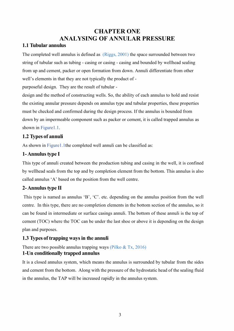
1.1 Tubular annulus The completed well annulus is defined as (Riggs, 2001) the space surrounded between two
string of tubular such as tubing - casing or casing - casing and bounded by wellhead sealing
from up and cement, packer or open formation from down. Annuli differentiate from other
well’s elements in that they are not typically the product of -
purposeful design. They are the result of tubular -
design and the method of constructing wells. So, the ability of each annulus to hold and resist
the existing annular pressure depends on annulus type and tubular properties, these properties
must be checked and confirmed during the design process. If the annulus is bounded from
down by an impermeable component such as packer or cement, it is called trapped annulus as
shown in Figure1.1.
1.2 Types of annuli As shown in Figure1.1the completed well annuli can be classified as:
1- Annulus type I This type of annuli created between the production tubing and casing in the well, it is confined
by wellhead seals from the top and by completion element from the bottom. This annulus is also
called annulus ‘A’ based on the position from the well centre.
2- Annulus type II This type is named as annulus ‘B’, ‘C’. etc. depending on the annulus position from the well
centre. In this type, there are no completion elements in the bottom section of the annulus, so it
can be found in intermediate or surface casings annuli. The bottom of these annuli is the top of
cement (TOC) where the TOC can be under the last shoe or above it is depending on the design
plan and purposes.
1.3 Types of trapping ways in the annuli There are two possible annulus trapping ways (Pilko & Tx, 2016) 1-Un conditionally trapped annulus It is a closed annulus system, which means the annulus is surrounded by tubular from the sides
and cement from the bottom. Along with the pressure of the hydrostatic head of the sealing fluid
in the annulus, the TAP will be increased rapidly in the annulus system.
4
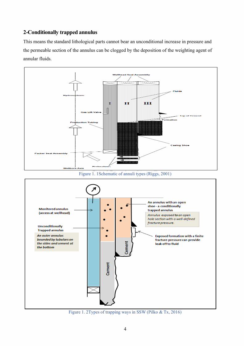
2-Conditionally trapped annulus This means the standard lithological parts cannot bear an unconditional increase in pressure and
the permeable section of the annulus can be clogged by the deposition of the weighting agent of
annular fluids.
Figure 1. 1Schematic of annuli types (Riggs, 2001)
Figure 1. 2Types of trapping ways in SSW (Pilko & Tx, 2016)
5
1.4 Annular pressure From the previous definitions, it can easily define it as the pressure that generates by the annular
fluid inside the annulus due to volume expansion, fluid migration into the annulus, or operator
intentionally performing. Or in a special case can generate accidently due to uncontrol flow from
well. It will be normal in case of annular pressure less than the permissible limit and abnormal if it
exceeds permissible limits.
1.5 Types of annular pressure There are three major types of annular pressures (Sangesland, S., Rausand, 2012), thermal Pressure
also known as (TAP or APB), SCP also is known as SAP and Applied Pressures. We focus on the
first two types because it can be abnormal and harmful, these will be discussed as follow:
1.5.1 Thermal pressure This type of annular pressure happens due to the thermal expansion of the trapped fluid in the
annulus. Thermal pressure is recognized by bleeding (when possible) it will stable at bleeding
value (no build-up again). The major basic conditions that must be found for generation TAP are
two. First, is the heat source redistributing the temperature of the wellbore? Second, the closed
annulus zone is filled with low compressibility sealed liquid to have a fluid volume change
(Zhang et al., 2017).
1.5.1.1 Feature that characterizes thermal pressure loads To analyse thermal pressure, the list of the features that characterize its loads in HPHT and SSW
must be introduced for each annulus (Sathuvalli et al., 2016).
1- Unconditionally potential of developing APB, the pressure increases in addition to hydrostatic
of the fluid in the annulus it is led to extra pressure can cause early severe failure to the casing
strength loads.
2- The annuals are bounded by inner and outer string, the greatest differential pressure (burst or
collapse load) happened when one side of the annulus has a TAP and the neighbouring annulus
have not. Irrespective of the operational situation that creates the TAP, this assumption reflects
the condition that gives rise to the most severe differential loads on the strings of the annulus.
3- The temperature change during production or drilling phases will be larger at shallower and
colder outer annuli. Therefore, outer annuli can sometimes develop higher APB relative to the
inner annuli.
4- The profiles of pore and fracture pressure that already showed increases with depth, the
outcome of the drilling process is that the outer string is design to face a lower MASP so it has a
6
larger ratio between outer diameter and thickness (Dout/t) compared to the inner followed casing
strings(production, liners…etc.).
5- The collapse of the inner string in the trapped annulus is likely to accrue before the rupture of
the outer string. Therefore, an APB load has the potential to cause the collapse of the frontal inner
string and cascade toward the production tubing (P. D. Pattillo et al., 2007).
6- The management of the integrity of SSW (to production induced APB loads) cannot be
simplified by adjusting tubular strength, annular pressure must be mitigated and managed during
the life of the well.
1.5.1.2 Factors affecting thermal pressure Some factors affect the amount of generated TAP, as follow:
1- Fluid thermodynamic property The numerical coefficient linked the thermal expansion and fluid compressibility in most cases
of calculations are consider constant, but in the reality, these coefficients are changed as a
function of temperature even the temperature change is the same. There are different range of
annular pressure in different temperature, so there is an inaccurate calculation of ABP, for that
reason must consider the coefficient of temperature-dependent of thermal expansion and
compressibility of the trapped fluid But, the problem concentrate at the difficulty of getting the
coefficient of thermal expansion and compressibility of mud/fluid in the annulus however a
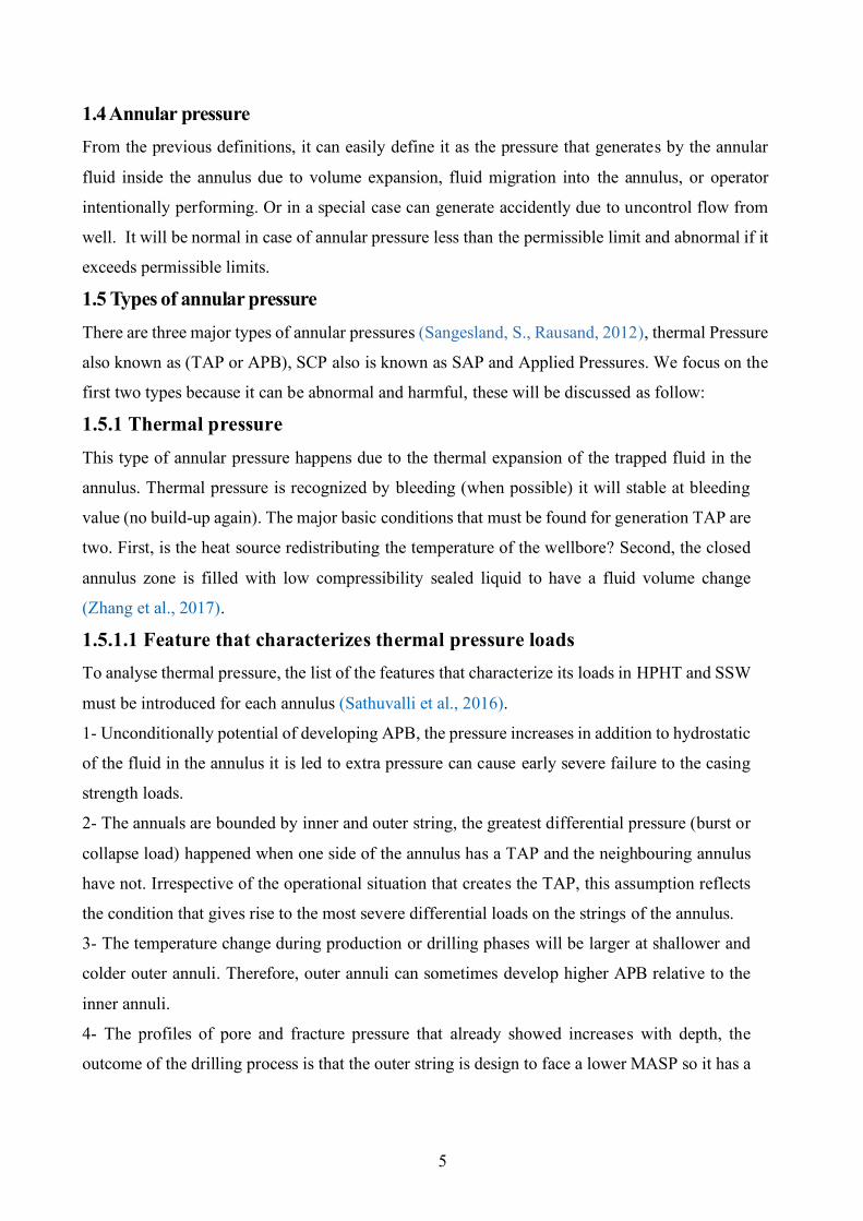
published research (Yin & Gao, 2014) indicate that synthetic mud (annular sealing fluid)
thermodynamic property are similar to tap water as shown in Figure1.3 so, the thermodynamics
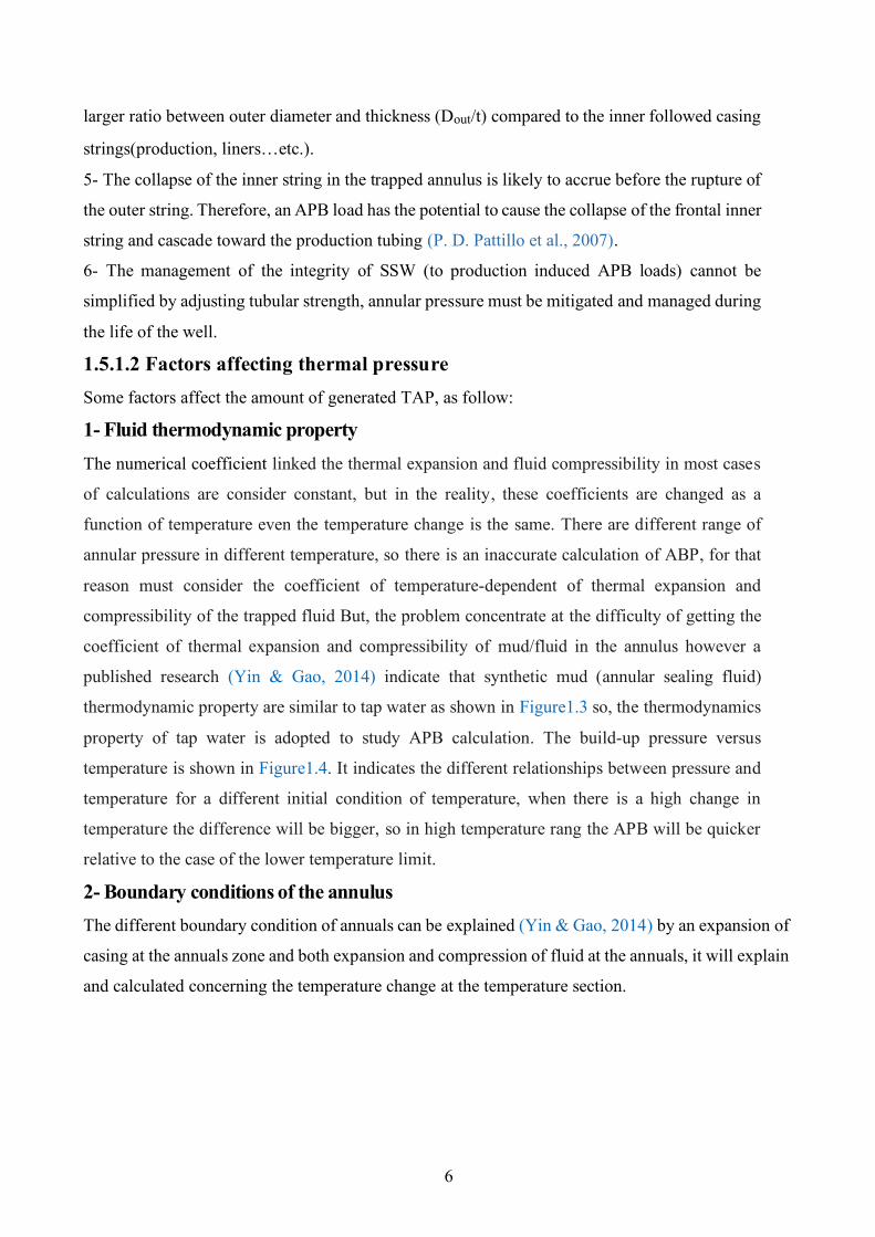
property of tap water is adopted to study APB calculation. The build-up pressure versus
temperature is shown in Figure1.4. It indicates the different relationships between pressure and
temperature for a different initial condition of temperature, when there is a high change in
temperature the difference will be bigger, so in high temperature rang the APB will be quicker
relative to the case of the lower temperature limit.
2- Boundary conditions of the annulus The different boundary condition of annuals can be explained (Yin & Gao, 2014) by an expansion of
casing at the annuals zone and both expansion and compression of fluid at the annuals, it will explain
and calculated concerning the temperature change at the temperature section.
7
Figure 1. 3 Pressure versus temperature from experimental data (Yin & Gao, 2014)
Figure 1. 4 APB versus temperature change in various temperature ranges (Yin & Gao, 2014)
8
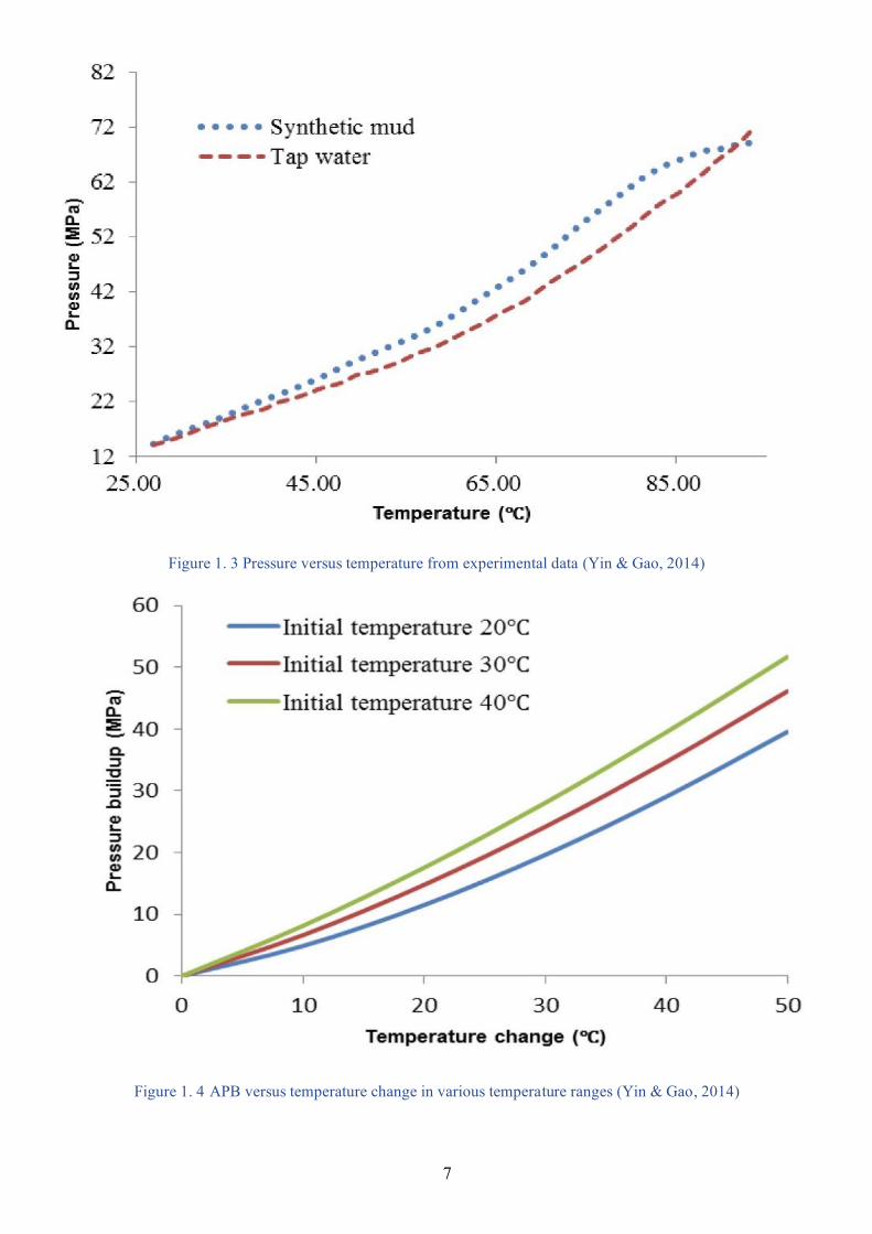
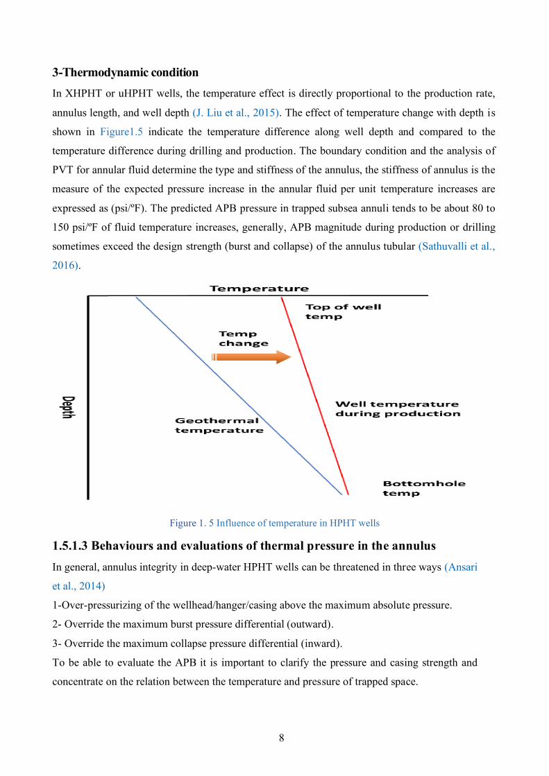
3-Thermodynamic condition In XHPHT or uHPHT wells, the temperature effect is directly proportional to the production rate,
annulus length, and well depth (J. Liu et al., 2015). The effect of temperature change with depth is
shown in Figure1.5 indicate the temperature difference along well depth and compared to the
temperature difference during drilling and production. The boundary condition and the analysis of
PVT for annular fluid determine the type and stiffness of the annulus, the stiffness of annulus is the
measure of the expected pressure increase in the annular fluid per unit temperature increases are
expressed as (psi/ºF). The predicted APB pressure in trapped subsea annuli tends to be about 80 to
150 psi/ºF of fluid temperature increases, generally, APB magnitude during production or drilling
sometimes exceed the design strength (burst and collapse) of the annulus tubular (Sathuvalli et al.,
2016).
Figure 1. 5 Influence of temperature in HPHT wells
1.5.1.3 Behaviours and evaluations of thermal pressure in the annulus In general, annulus integrity in deep-water HPHT wells can be threatened in three ways (Ansari
et al., 2014)
1-Over-pressurizing of the wellhead/hanger/casing above the maximum absolute pressure.
2- Override the maximum burst pressure differential (outward).
3- Override the maximum collapse pressure differential (inward).
To be able to evaluate the APB it is important to clarify the pressure and casing strength and
concentrate on the relation between the temperature and pressure of trapped space.
9
There are four types of evaluation methods can be applied to estimate the ABP, these methods
are (Dong & Chen, 2017)
I- Measurement of annular pressure practically by installing a gauge on the annulus ‘A’ for
pressure and temperature measurement these devices can be wired or wireless gauges.
II- Measurement of APB by using experimental internal simulation with creating a synthetic
environment in the special lab to simulate the APB by pressure and temperature change that can
occur in a real environment. Also, this type can be used for mitigation techniques testing, and
evaluation.
III- Using prediction modelling for estimation of APB. This model is establishing depending on
the fundament of energy conservation, PVT state equation, and wellbore heat transference
equation. It is the more accepted one for engineering calculation especially the analytical one.
This type is applied for designing purposes.
IV- Smart observation method for annular pressure of tubing and casing during well life.
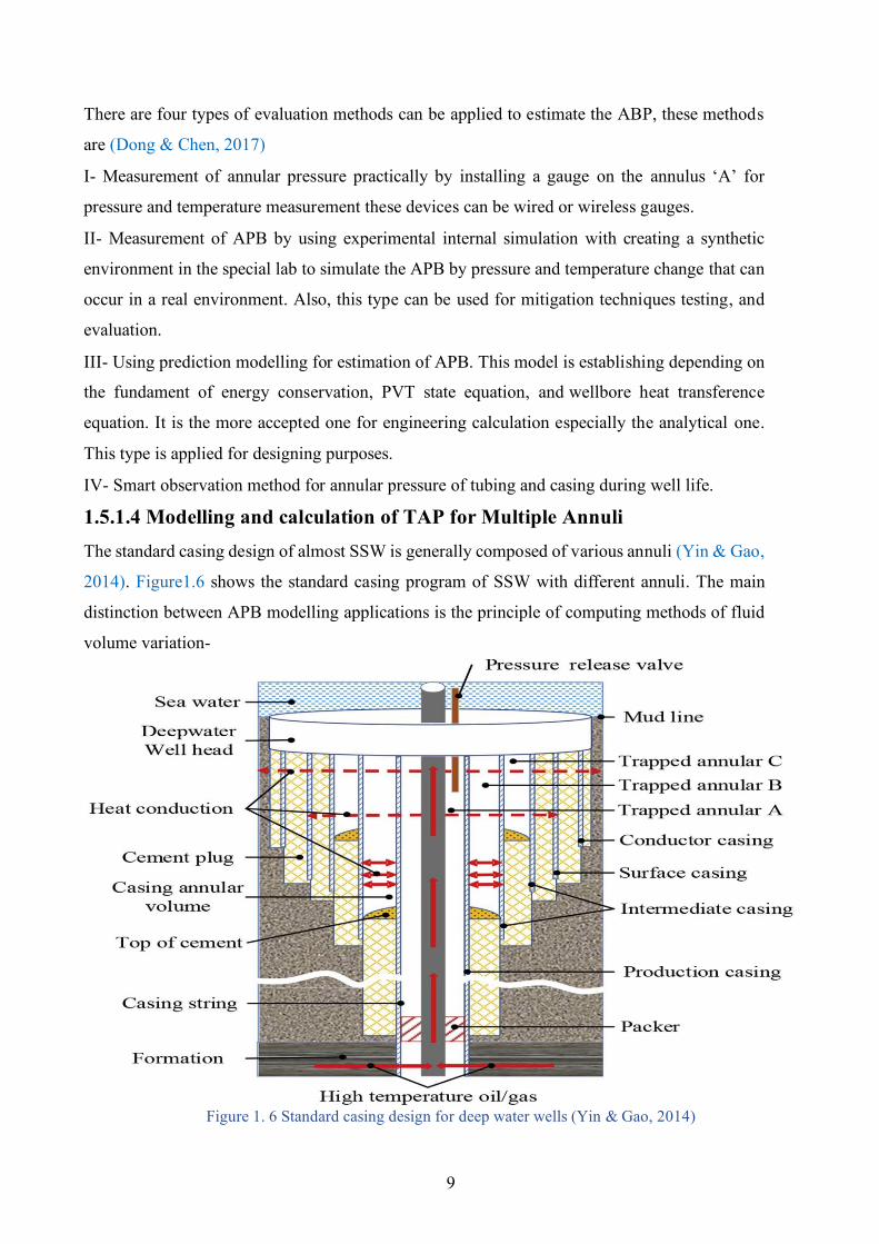
1.5.1.4 Modelling and calculation of TAP for Multiple Annuli The standard casing design of almost SSW is generally composed of various annuli (Yin & Gao,
2014). Figure1.6 shows the standard casing program of SSW with different annuli. The main
distinction between APB modelling applications is the principle of computing methods of fluid
volume variation-
Figure 1. 6 Standard casing design for deep water wells (Yin & Gao, 2014)
10
(Sathuvalli et al., 2005), (Oudeman & Kerem, 2004). The application of a new unconventional
casing design(multi-string casing design) is based on the TAP effect on the annulus of casing
strings, this design needs to analyze and determine the annular pressure by using modules for
calculation (Halal & Mitchell, 1994). The TAP depends on the ability of the trapped fluid to
expand and the allowable annular space for expansion due to geometry changes as a result of
displacements of casings and tubing. The pressure increase will change the volume of the annular
space due to the elasticity of the steel (Adams, 1991). Based on Lame’s equations or thin wall
shell theory, the estimation of APB based on PVT fluid analysis, pressure with temperature
changes, and resultant volume change. The annular volume change as a result of some factors
that are thermal expansion of steel, compression of the internal casing, and ballooning of the
external casing. So we review the model developed by (Yin & Gao, 2014) to explain the way of
APB calculation for multiple annuli.
Model assumption: 1- The annular pressure at annulus ‘A’ is constant.
2- The annular temperature at annuli ‘B’ and ‘C’ approximately similar.
3- The changing of the annular temperature is uniform.
4- There is No leakage or influx in each annulus.
When the change in temperature of the annular occurred during well activities such as drilling,
well test, or production this change defined as ∆T, and the change in pressure of ‘B’ and ‘C’
annuli are defined as ∆P1, ∆P2 respectively, so the analysing of the annulus are built on two
sections:
1- Analyzing of annulus casing
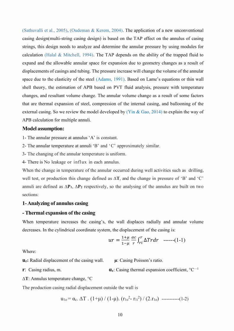
- Thermal expansion of the casing When temperature increases the casing’s, the wall displaces radially and annular volume
decreases. In the cylindrical coordinate system, the displacement of the casing is:
𝑢𝑟 =1+𝜇
1−𝜇 𝛼𝑐
𝑟∫ ∆𝑇𝑟𝑑𝑟
𝑟
𝑟𝑖 ------(1-1)
Where:
ur: Radial displacement of the casing wall. µ: Casing Poisson’s ratio.
r: Casing radius, m. αc: Casing thermal expansion coefficient, °C—1
∆T: Annulus temperature change, °C
The production casing radial displacement outside the wall is
u1o = αc. ∆T . (1+μ) / (1-μ). (r1o2- r1i
2) / (2.r1o) -----------(1-2)
11
Idioms mean
u1o: Production casing outside wall radial displacement.
r1i: Production casing internal radius, m. r1o: Production casing external radius m.
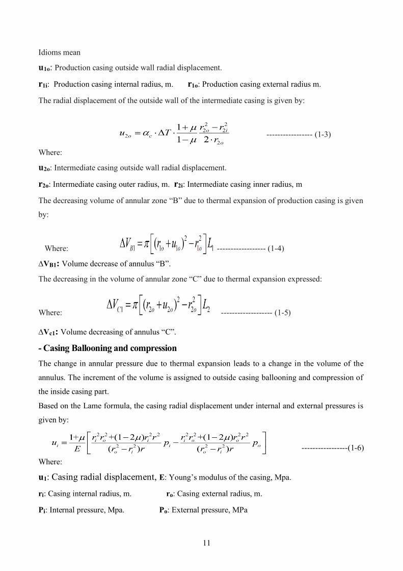
The radial displacement of the outside wall of the intermediate casing is given by:
----------------- (1-3)
Where:
u2o: Intermediate casing outside wall radial displacement.
r2o: Intermediate casing outer radius, m. r2i: Intermediate casing inner radius, m
The decreasing volume of annular zone “B” due to thermal expansion of production casing is given
by:
Where: ------------------ (1-4)
∆VB1: Volume decrease of annulus “B”.
The decreasing in the volume of annular zone “C” due to thermal expansion expressed:
Where: ------------------- (1-5)
∆Vc1: Volume decreasing of annulus “C”.
- Casing Ballooning and compression The change in annular pressure due to thermal expansion leads to a change in the volume of the
annulus. The increment of the volume is assigned to outside casing ballooning and compression of
the inside casing part.
Based on the Lame formula, the casing radial displacement under internal and external pressures is
given by:
-----------------(1-6)
Where:
u1: Casing radial displacement, E: Young’s modulus of the casing, Mpa.
ri: Casing internal radius, m. ro: Casing external radius, m.
Pi: Internal pressure, Mpa. Po: External pressure, MPa
12
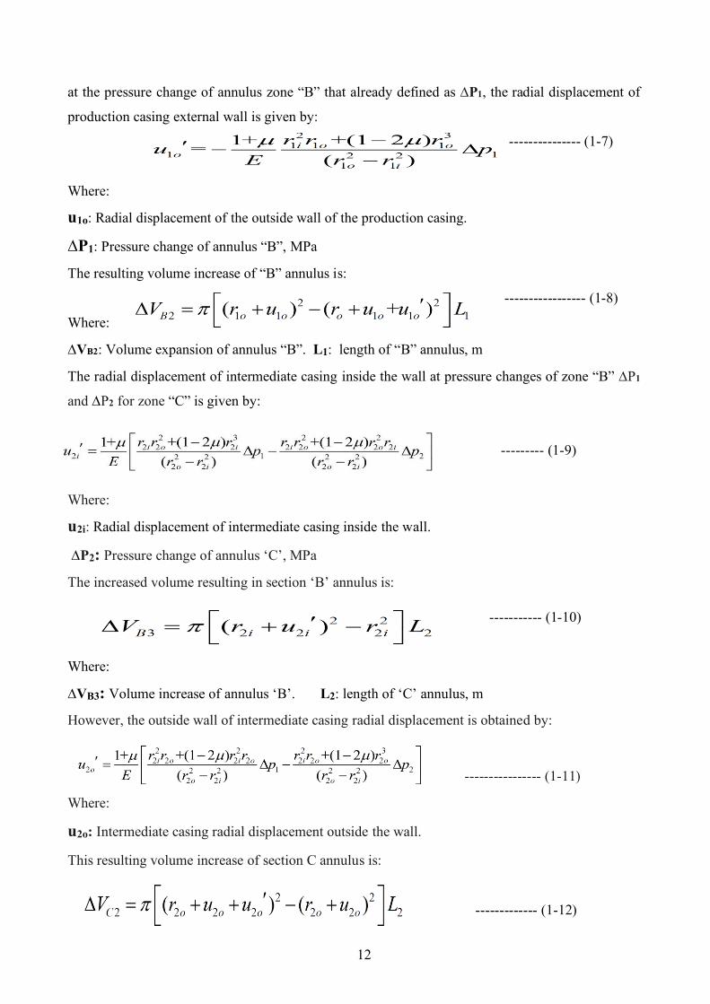
at the pressure change of annulus zone “B” that already defined as ∆P1, the radial displacement of
production casing external wall is given by:
--------------- (1-7)
Where:
u1o: Radial displacement of the outside wall of the production casing.
∆P1: Pressure change of annulus “B”, MPa
The resulting volume increase of “B” annulus is:
----------------- (1-8)
Where:
∆VB2: Volume expansion of annulus “B”. L1: length of “B” annulus, m
The radial displacement of intermediate casing inside the wall at pressure changes of zone “B” ∆P1
and ∆P2 for zone “C” is given by:
--------- (1-9)
Where:
u2i: Radial displacement of intermediate casing inside the wall.
∆P2: Pressure change of annulus ‘C’, MPa The increased volume resulting in section ‘B’ annulus is:
----------- (1-10)
Where:
∆VB3: Volume increase of annulus ‘B’. L2: length of ‘C’ annulus, m However, the outside wall of intermediate casing radial displacement is obtained by:
---------------- (1-11)
Where:
u2o: Intermediate casing radial displacement outside the wall.
This resulting volume increase of section C annulus is:
------------- (1-12)
13
Where:
∆VC2: Volume increase of annulus ‘C’.
2- Analysing of trapped fluid in the annulus
- Fluid thermal expansion
The fluid in the annular zone ‘B’ will be expanded due to the heat exchanging and the volume
increases under constant pressure is given by:
-------------------- (1-13)
Where:
∆VB4: Volume increase of the fluid of annulus ‘B’.
α1: Coefficient of thermal expansion of fluid, °C—1
The same for the fluid of annular zone of ‘C’ the volume is given by:
------------------- (1-14)
where:
∆VC4: Volume increase of the fluid of annulus ‘C’.
r3i: Surface casing inner radius, m.
- Fluid compression Due to pressure increase in the annular pressure, the fluid will be compressed in the annular ‘B’
and ‘C’. It can be expressed as:
------------ (1-15)
---------- (1-16)
Where:
∆VB5: Volume decrease in the fluid of annulus ‘B’.
∆VC5: Volume decrease in the fluid of annulus ‘C’.
κT: Compressibility of fluid, MPa—1 can be taken as tap water compressibility as mentioned
previously at the fluid thermodynamic property.
Therefore, the change in fluid volume should be equal to the change in casing annular volume.
The following expression can be applied
-∆VB1 + ∆VB2 + ∆VB3 = ∆VB4 - ∆VB5 --------------- (1-17)
-∆VC1 + ∆VC2 =∆VC4 - ∆VC5 -------------- (1-18)
14
By substation of formulas (1-1) ⁓ (1-16) into the formulas (1-17) ⁓ (1-18) the pressure changes
in the annular zones ‘B’ and ‘C’ that represented by ∆p1 and ∆p2 finally can be calculated.
The TAP of two annular zones can be solved from the above formulas it is almost covered all
situations of thermal expansion cause of generation of TAP, if there are three circular annuli need
to be calculated, a set of equation similar can be applied to do this calculation (these situations
are extremely rare). The aim of this development (modelling of APB) is to show one of the
possible ways for determining the APB and how this calculation can be applied with factors
affecting this calculation and show APB software’s working principle.
1.5.1.5 Phases of TAP occurrence There are three basic phases for TAP, production /stimulation, drilling, and uncontrol flow phase
that is known as worst-case discharge (WCD).
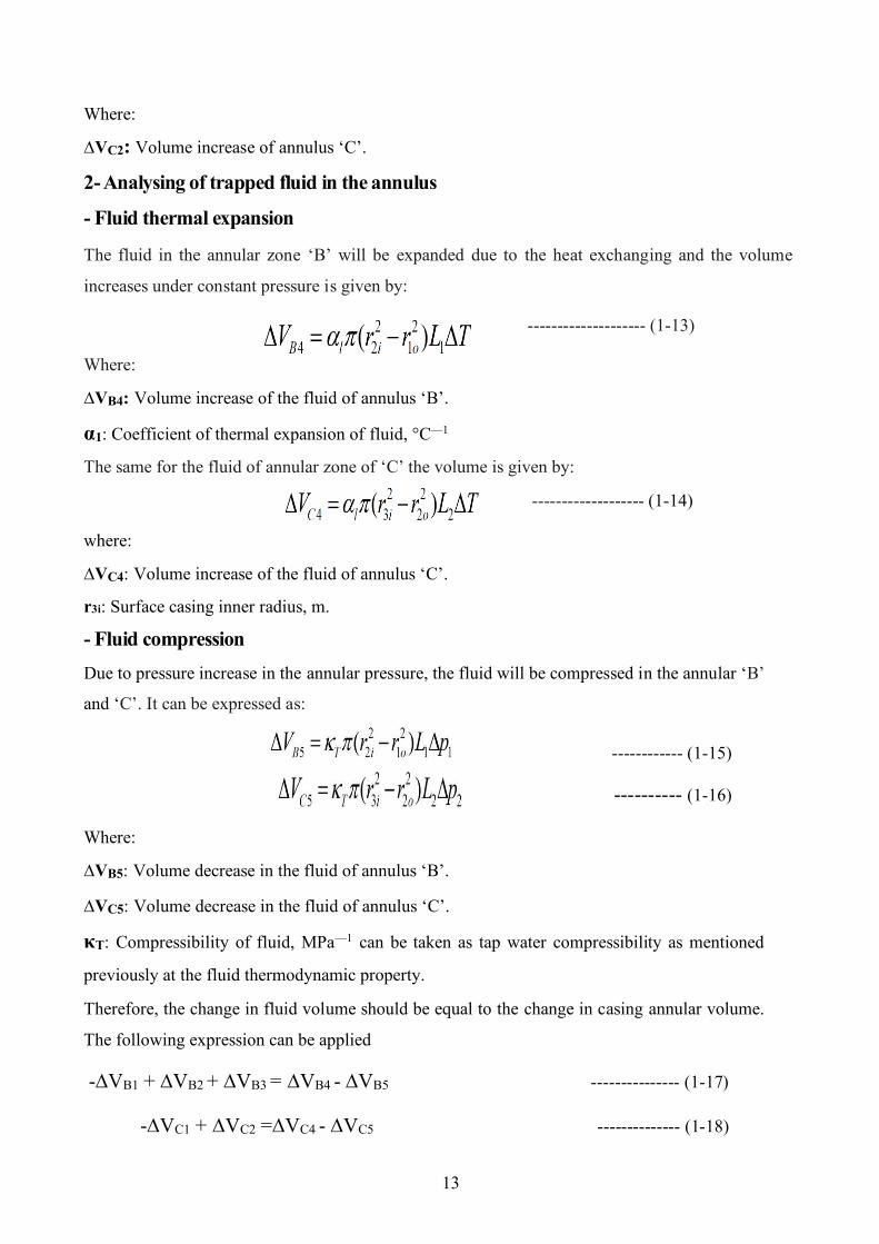
1-TAP in production and stimulation phase As reported at the sample well shown in Figure1.7 we can observe that the APB-
Figure 1. 7 Effection of Annulur pressure with production time (Zhang et al., 2016)
reaches a maximum recorded value (65 Mpa) within 600 days of production time. It is indicated
that the annular pressure starts to build up at the point of trapped fluid expanded due to the heat
exchanging and continues increasing proportional to production time, but the speed of expansion
decreases with time due to a decrease of the temperature difference between the annulus and
15
produced fluid. The maximum pressure is recorded at the highest production time that suspects
the highest TAP for casing design failure scenarios.
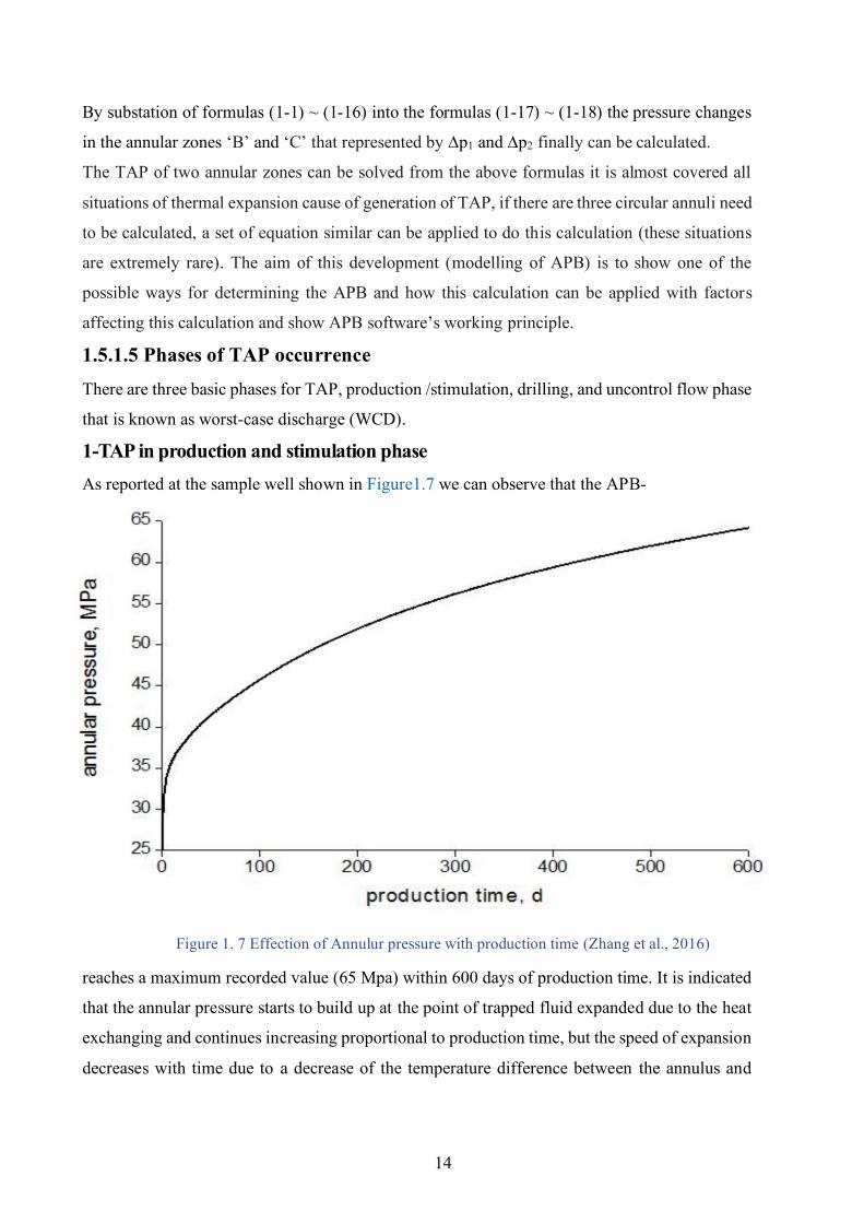
2-TAP in the drilling phase In the previous case TAP analysis, casing failure accrued at the production well, but in the case
of the drilling operation, the same problem can be happened due to heating by drilling mud that
carries the heat from the bottom hole to the upper part of the well (Phillip D. Pattillo, Cocales, et
al., 2004). In HPHT for deep-water SSW or some land wells the temperature of the sealing fluid
in the multi annuli (in the upper part of well) is low (about 4ºC) and it is reached to (120 - 500)ºC
or more for the deeper section at the bottom of the hole, as shown in Figure1.8 the hot mud when
carrying up the heating to the upper part of well can generate TAP which looms up the integrity
of casing and wellhead that can cause a stick of drill string as a result of the existing casing
collapse.
Figure 1. 8 Sketch map of TAP during drilling (Zhang et al., 2019)
As reported the problem of sticking drill string in well pompano A-31 in GOM due to damage of
16ʺ casing (Zhang et al., 2016). The annular pressure prediction will be fundamental when
drilling goes deeper (J. Liu et al., 2017). The same approach that was explained previously at
APB modelling is used to calculate TAP and accounted for in casing design and TAP mitigation
techniques.
16
3-TAP in WCD This is a special case of TAP happen accidentally in some cases of uncontrolled flow from the well due to loss of well control, so the high uncontrol flow will cause a high temperature come from the bottom hole, and as a consequence, the trapped annular volume will expand highly and generate high TAP can cause huge damage to well integrity if it is not accounted properly. For offshore HPHT wells, the WCD, as introduced by the Bureau of Safety and Environmental Enforcement (BSEE), is the empty hole (no drill string in the hole) uncontrol flow to the seabed with a fully opened reservoir and no flow limitation. WCD analysis was authorized by the U.S. government after the disaster of the “Deepwater Horizon oil spill” happened. WCD is calculated by linking a reservoir/inflow model to a nodal analysis model (Ansari et al., 2014) 1.5.1.6 Possible cases and locations of trapped annuli There is some location the designer must be expecting trapped annulus occurrence and make their
analysis before making the well design.
1- Deepwater wells Deep-water wells contain various annuli resulted from the complex casing construction and
cementing technology (Zhang et al., 2016). The Subsea wellhead is generally taking in the deep-
water section, also the annuli are isolated beneath the seafloor by wellhead. The annular liquid
temperature raises during drilling and production operations due to the high-temperature difference
between the fluid inside the well and the surrounded environment of the annulus. As a consequence,
for this reason, TAP widely appears in deep water wells. As examples reported in GOM, South China
Sea, and more.
2- Wells in gas storage and high-temperature gas field TAP can happen in gas filed recognized by a high-temperature or in gas storage because of the
annulus created by the production casing and the tubing is injected with conservative materials to
avoid acid corrosion and reduces the pressure difference on packers. So this liquid will expand and
create a high TAP, as reported cases in gas storage in “North China, Xinjiang Province in China, and
Sichuan Yuanba and Puguang gas fields” (Halliburton, 2012).
3- Multiple packers oil and gas wells This technique is mostly used in wells to perform staged fracturing or isolated layer stimulation.
As shown in Figure1.9. Trapped space is generated between closer packers. Similarly, the space
trapped between the liner hanger and the packers will also permit the creation of TAP. The same
problem was happened in “Tarim Oil Filed, Elly & Luke Oil Field in the North Sea, Denmark, and
Magnolia Oil Field in GOM” (Zhang et al., 2019).
17
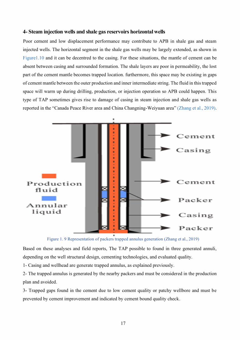
4- Steam injection wells and shale gas reservoirs horizontal wells Poor cement and low displacement performance may contribute to APB in shale gas and steam
injected wells. The horizontal segment in the shale gas wells may be largely extended, as shown in
Figure1.10 and it can be decentred to the casing. For these situations, the mantle of cement can be
absent between casing and surrounded formation. The shale layers are poor in permeability, the lost
part of the cement mantle becomes trapped location. furthermore, this space may be existing in gaps
of cement mantle between the outer production and inner intermediate string. The fluid in this trapped
space will warm up during drilling, production, or injection operation so APB could happen. This
type of TAP sometimes gives rise to damage of casing in steam injection and shale gas wells as
reported in the “Canada Peace River area and China Changning-Weiyuan area” (Zhang et al., 2019).
Figure 1. 9 Representation of packers trapped annulus generation (Zhang et al., 2019)
Based on these analyses and field reports, The TAP possible to found in three generated annuli,
depending on the well structural design, cementing technologies, and evaluated quality.
1- Casing and wellhead are generate trapped annulus, as explained previously.
2- The trapped annulus is generated by the nearby packers and must be considered in the production
plan and avoided.
3- Trapped gaps found in the cement due to low cement quality or patchy wellbore and must be
prevented by cement improvement and indicated by cement bound quality check.
18
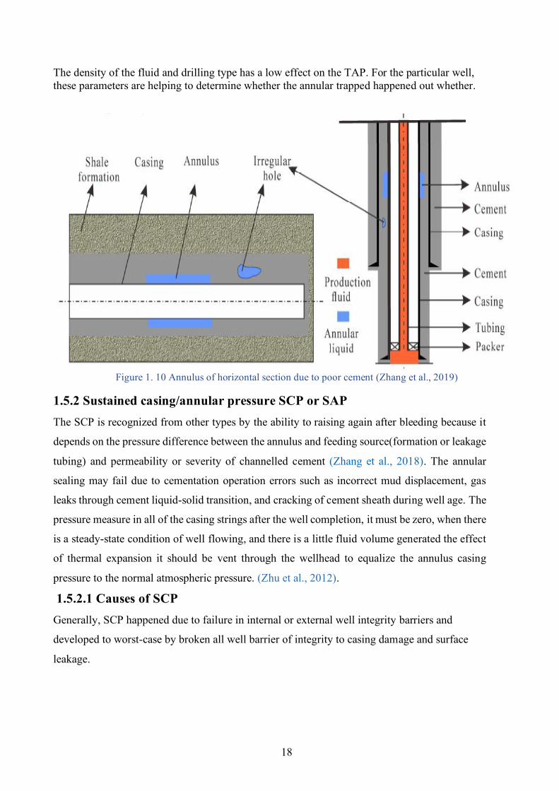
The density of the fluid and drilling type has a low effect on the TAP. For the particular well, these parameters are helping to determine whether the annular trapped happened out whether.
Figure 1. 10 Annulus of horizontal section due to poor cement (Zhang et al., 2019)
1.5.2 Sustained casing/annular pressure SCP or SAP The SCP is recognized from other types by the ability to raising again after bleeding because it
depends on the pressure difference between the annulus and feeding source(formation or leakage
tubing) and permeability or severity of channelled cement (Zhang et al., 2018). The annular
sealing may fail due to cementation operation errors such as incorrect mud displacement, gas
leaks through cement liquid-solid transition, and cracking of cement sheath during well age. The
pressure measure in all of the casing strings after the well completion, it must be zero, when there
is a steady-state condition of well flowing, and there is a little fluid volume generated the effect
of thermal expansion it should be vent through the wellhead to equalize the annulus casing
pressure to the normal atmospheric pressure. (Zhu et al., 2012).
1.5.2.1 Causes of SCP Generally, SCP happened due to failure in internal or external well integrity barriers and
developed to worst-case by broken all well barrier of integrity to casing damage and surface
leakage.
19
1.5.2.1.1 SCP by internal integrity failure It is happening as a result of tubbing leaking inside the annulus, or seepage between casing
strings. This cause is likely to occur when the tubular impacted by corrosion, poor connection of
threads, thermal stress cracking, or rupture happened mechanically (Riggs, 2001). It can be
indicated quickly by changing inside string pressure and observe the casing pressure, if there is
an equilibrium that means it is linked by the leak. Or in some cases can be indicated from routine
production records. This is a recurrent case of SCP and it can easily be recovered by well work-
over operations.
1.5.2.1.2 SCP by external integrity failure In this case, the pressure generated due to passageway from pressured zone such as hydrocarbon-
bearing, water-bearing, shallow gas zone, shallow water zone, or of biogenic origin. This case
technically difficult repairing and can cause poor zonal isolation and risk to the casing loads
integrity. Furthermore, it may cause surface leaking (Rocha-Valadez et al., 2014). External
integrity failure can happen due to:
1- Poor cementing Occurred when the gas migrates from its zone to the upper annular part due to the bad or
channelling cement bond between casing and formation and pressure difference.
2- Failure of primary cement after setting and generation of micro-fractures The casing, cement, and formation will have a big variation in elastoplastic between cement and
casing at CCI and when the thermal displacement reaches a specific level, the cement will be
converted from elastic to plastic deformation. Plastic deformation cannot be recovered. As a
result, the casing displacement can be recovered when the casing internal pressure decreases
while cement cannot. Cement and casing will no longer be still located in close contact when
tensile stress override the interface bonding strength, and then displacement variation occurred
between the cement internal surface and casing outer surface (Zhang et al., 2018), the
microfracture will be generated and provide a passageway for the pressured fluid to flow up into
the annulus. Also, micro-annulus/channelling in the annular cement sheath can occur due to bad
mud displacement during cementation (Mwang’Ande et al., 2019). This poor isolation will
eventually lead to the flow of water or gas and generate SCP (Animesh Kumar et al., 2017).
There is some parameter affecting this annular pressure (in case of gas migration) These
specifications concern but are not limited to the existence and volume of the gas cap at the head
of the casing, the height of the mud column as well as the permeability of the gas through the
cement column (Bourgoyne et al., 2000).
20
1.5.2.2 Modelling of SCP The model appropriate for accounting of SCP that is fixed for the transmission process of the
system. Statistical indication shows the probability of SCP occurrence increases during the well
ages. To analyse, calculate SCP, and then be able to account for the risk for SCP and get the
optimum well design or select optimum remediation operation. (Milanovic & Smith, 2005), we
present an analytical solution published by (Rocha-Valadez et al., 2014), a gas model that
migrates up the annulus through both the cement sheath and the liquid column, to show the
possible way for determining SCP and apply it in calculations.
-Model assumption 1- Vertical flow of gas in the annulus through the liquid column.
2- Constant mud density and formation pressure.
3- Slightly compressible fluid.
4- The well produces at a constant rate to ensure that the oscillating flow at the pipe does not
encourage any heat transfer that affects the result of the calculation.
- Formulation of the model
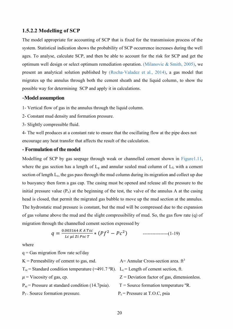
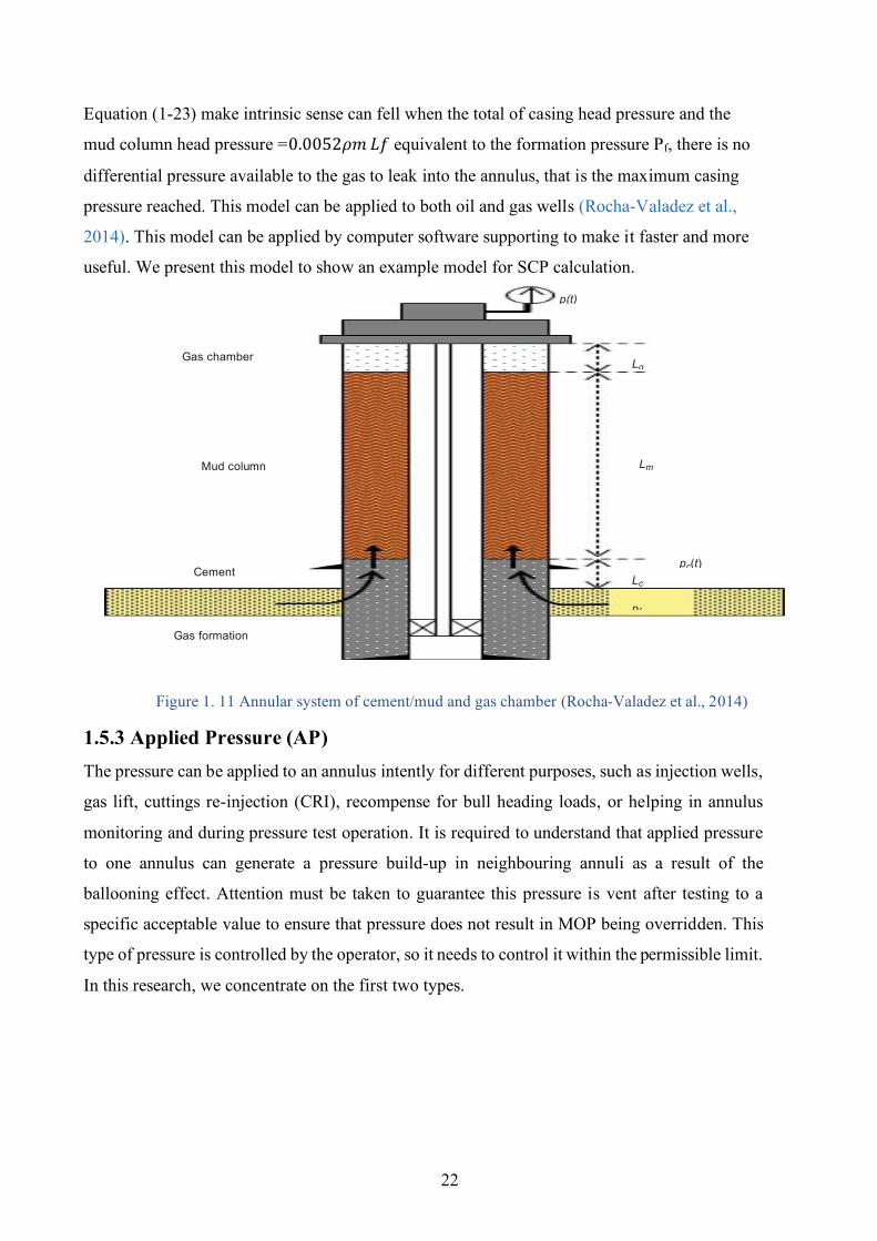
Modelling of SCP by gas seepage through weak or channelled cement shown in Figure1.11,
where the gas section has a length of Lg and annular sealed mud column of Lf, with a cement
section of length Lc, the gas pass through the mud column during its migration and collect up due
to buoyancy then form a gas cap. The casing must be opened and release all the pressure to the
initial pressure value (Po) at the beginning of the test, the valve of the annulus A at the casing
head is closed, that permit the migrated gas bubble to move up the mud section at the annulus.
The hydrostatic mud pressure is constant, but the mud will be compressed due to the expansion
of gas volume above the mud and the slight compressibility of mud. So, the gas flow rate (q) of
migration through the channelled cement section expressed by
𝑞 =0.003164 𝐾 𝐴 𝑇𝑠𝑐
𝐿𝑐 𝜇𝑖 𝑍𝑖 𝑃𝑠𝑐 𝑇∗ (𝑃𝑓2 − 𝑃𝑐2) ----------------(1-19)
where
q = Gas migration flow rate scf/day
K = Permeability of cement to gas, md. A= Annular Cross-section area. ft3
Tsc = Standard condition temperature (=491.7 ºR). Lc = Length of cement section, ft.
𝜇 = Viscosity of gas, cp. Z = Deviation factor of gas, dimensionless.
Psc = Pressure at standard condition (14.7psia). T = Source formation temperature ºR.
Pf = Source formation pressure. Pc = Pressure at T.O.C, psia
21
Gas moles (n) are calculated by using gas law P V = n R T
where P is the pressure of the gas cap, V is the volume of gas, T is gas temperature, R is the
constant of gas (=10.731ft^3.psi/ºR.Ib-mol).
The change in gas volume can be accounted for by the compressibility of the mud section.
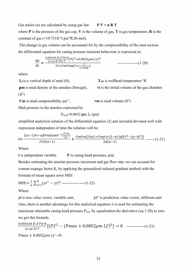
the differential equation for casing pressure transient behaviour is expressed as:
𝑑𝑝
𝑑𝑡=
0.003164 𝐾 𝐴 𝑇𝑤 ℎ
𝐿𝑐 𝜇𝑖 𝑍𝑖 𝑃𝑠𝑐 𝑇(𝑃𝑓2+0.0052𝜌𝑚 𝐿𝑓)2
𝑉𝑖+𝐶𝑚𝑉𝑚𝑝(1+1
1+𝐶𝑚𝑝 )
----------------(1-20)
where
Lf is a vertical depth of mud (ft), Twh is wellhead temperature ºR
𝛒m is mud density at the annulus (Ibm/gal), vi is the initial volume of the gas chamber
(ft3)
Cm is mud compressibility psi-1, vm is mud volume (ft3)
Mud pressure in the annulus expressed by
Pmud=0.0052 𝛒m Lf (psi)
simplified analytical solution of the differential equation (2) and included deviated well with
expression independent of time the solution will be:
t=⌊(𝛼−1)𝑉𝑖−𝛼𝛽𝑉𝑚⌋𝑡𝑎𝑛ℎ−1(
𝑃+𝑏
𝑃𝑓)
𝑃𝑓𝑑(𝛼−1)+
𝐶𝑚𝑉𝑚{2 ln(1+𝐶𝑚𝑝)+(2−𝛼) ln[𝑃𝑓2−(𝑝−𝑏)2]}
2𝑑(𝛼−1) -------(1-21)
Where
t is independent variable P is casing head pressure, psia
Besides estimating the annular pressure increment and gas flow rate, we can account for
cement seepage factor Ks by applying the generalized reduced gradient method with the
formula of mean square error MSE
MSE=1
𝑛∑ (𝑦𝑖∧ − 𝑦𝑖)2𝑛
𝑖=1 ------------------(1-22)
Where
yi is true value vector, variable unit, yi^ is prediction value vector, different unit
Also, there is another advantage for this analytical equation it is used for estimating the
maximum attainable casing head pressure Pmax by equalization the derivative (eq 1-20) to zero
we got this formula 0.003164 𝐾 𝐴 𝑇𝑤 ℎ
𝐿𝑐 𝜇𝑖 𝑍𝑖 𝑇[(𝑃𝑓2 − (𝑃𝑚𝑎𝑥 + 0.0052𝜌𝑚 𝐿𝑓)2] → 0 --------------(1-23)
𝑃𝑚𝑎𝑥 + 0.0052𝜌𝑚 𝐿𝑓→Pf
22
Equation (1-23) make intrinsic sense can fell when the total of casing head pressure and the
mud column head pressure =0.0052𝜌𝑚 𝐿𝑓 equivalent to the formation pressure Pf, there is no
differential pressure available to the gas to leak into the annulus, that is the maximum casing
pressure reached. This model can be applied to both oil and gas wells (Rocha-Valadez et al.,
2014). This model can be applied by computer software supporting to make it faster and more
useful. We present this model to show an example model for SCP calculation.
Figure 1. 11 Annular system of cement/mud and gas chamber (Rocha-Valadez et al., 2014)
1.5.3 Applied Pressure (AP) The pressure can be applied to an annulus intently for different purposes, such as injection wells,
gas lift, cuttings re-injection (CRI), recompense for bull heading loads, or helping in annulus
monitoring and during pressure test operation. It is required to understand that applied pressure
to one annulus can generate a pressure build-up in neighbouring annuli as a result of the
ballooning effect. Attention must be taken to guarantee this pressure is vent after testing to a
specific acceptable value to ensure that pressure does not result in MOP being overridden. This
type of pressure is controlled by the operator, so it needs to control it within the permissible limit.
In this research, we concentrate on the first two types.
p(t)
Gas chamber gL
Mud column mL
Cement )t(cp cL
fp
Gas formation
23
CHAPTER TWO DESIGNING OF ANNULAR PRESSURE MITIGATION
TECHNIQUES
In this part, we discuss the possible solution for the annular pressure effect by applying a
mitigation device for TAP and mitigation methods for SCP, also possible remediation methods
that can be applied for well with damage due to SCP.
2.1 Mitigation of TAP In most drilled HPHT wells, the TAP raised quickly at a rate of approximately 30 psi/min to
reach a maximum value of 5000 to 8000+ psi, this pressure will threaten well integrity by possible
annulus casing failure (Sathuvalli et al., 2005). For the land HPHT wells, this TAP can be easily
vented from the wellhead. But in the SSW, “annulus ‘A’” is the only attainable annulus, and the
other annuli can’t be controlled. So, it needs to design a new technique to protect casing integrity
against TAP. It is a technique used to reduce or keep the TAP within the permissible range. The
design of an APB mitigation strategy is focused on knowing how each subject annulus and
mitigation system would react to the pressure-temperature in the wellbore. The mitigation system
triggered an "operating point" predetermined. The operating point characterized by the thermal
condition in that annulus and it is connected to the permissible APB. The using of mitigation
device are introduced in unconventional casing design as survival design.
The survival design means the design of structure under extreme magnitude loads that may be
accrued either with very low probability, but it can cause huge damage to the structure when this
loads will happen, especially for deep-water HPHT wells, the loads applied is abnormal annular
pressure and the risk is the loss of well integrity by structure damage, such loads cannot be
modified by conventional design (Suryanarayana & Lewis, 2016).
2.2 Function of TAP mitigation device The mitigation device must be able to (Phi et al., 2019)
1- Hold up the maximum expected loads to control pressure in the worst case.
2- Prevent casing failure at annulus with high unexpected thermal pressure.
3- Provide a barrier to improve and protect well integrity during well life (high reliability).
2.3 Design procedure for TAP mitigation 1-Select the annulus section (‘A’, ‘B’, ‘C’…. etc.) with the expecting of abnormal pressure
occurring.
24
2- Confirm factors of initiating the TAP (thermal exchanging that can make fluid expand and
restricted annulus). Risk analysis can detect this hazard.
3- Calculate APB for both drilling and production scenarios with annulus analysis by applying a
model of calculation as mentioned previously.
4- Compare the TAP value with the allowable value that is already defined by analysing annulus
string properties (collapse and burst).
5- If TAP < Allowable annular pressure ‣‣‣ The design acceptable. Risk analysis indicates the
level of risk and possible future failure to take into account if it needs any modification during
design.
6- If TAP > Allowable annular pressure ‣‣‣ Risk case, then go to step (7).
7- Check if the annulus is trapped conditionally or unconditionally. This part is a critical section
on design because it needs accurate analysis and a lot of scenarios to check the open section (if
presence) ability to protect annulus.
A- If the annulus is unconditionally trapped for annulus ‘A’
TAP can be observed and vented, the design acceptable after evaluating the risk of well integrity.
In some companies' policies, the venting device for the annulus ‘A’ is not accepted and a
mitigation device must be selected.
B- If the annulus is unconditionally trapped for annulus ‘B’, ‘C’, etc.
The casing strength modification or mitigation device must be applied.
8- First modify the tubular by redesign it (increase strength, change the size, weight grade
possible), if the new allowable APB of the new design becomes greater than TAP the design
accepted after a risk analysis, otherwise go to step (9).
9- Design a mitigation device based on TAP magnitude, condition of the annulus, production
rate, pressure and temperature profile, trapped fluid composition, expected well age, production
plan, and the most important part of design decided after a risk analysis.
10- Optimize selection of mitigation device, by applying risk analysis and cost-benefit analysis
with possible implementation mitigation device then select the optimum from the list of possible
design.
11- Uncertainty and lack of data or used expected value are negatively impact the design and
selection, so the designer must be far as possible from these criteria during design and analysis.
12- Cost is one of the design criteria and limitation but it not the target because failure means
loss of well barrier (casing and/or wellhead) of well integrity or may lead to lost the well, also
the remediation for this failure (if possible to remediate) costed much more the prevention.
25
13- Standard such as API, ISO, Norsok…etc. and government rules must be included during the
design and selection of mitigation devices.
2.4 Common techniques for APB Mitigation Based on effective mitigation time there are two major categories of applied mitigation
techniques (Zhang et al., 2016).
2.4.1 Active mitigation methods This type of mitigation technique is based on preventing abnormal annular pressure generation by
eliminating its causes. These techniques principled on wholly annulus cementing, isolate heat
source and decrease generated heat from the source.
1- Cementing to surface: Trapped annulus will eliminate when the cement top is back to the
wellhead.
2- Thermal-isolated pipes: They can enhance wellbore heat transfer resistance, and then reduced
the speed of pressure increasing.
3- Heat-isolated liquid: Inject this treated liquid in the casing-tubing annulus zone to improve
heat transfer strength.
4- Decrease production rate: Reducing the rate of production leads to less heat transportation into
the wellbore, so annular pressure will be lowered.
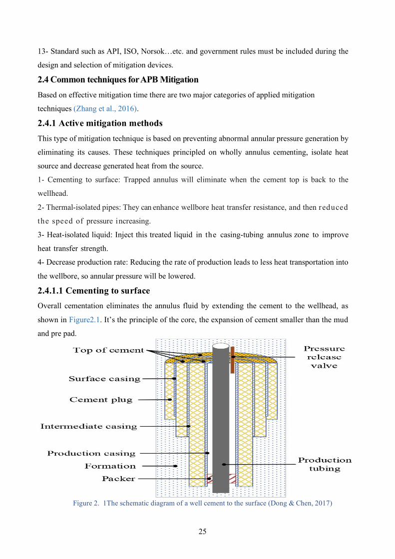
2.4.1.1 Cementing to surface Overall cementation eliminates the annulus fluid by extending the cement to the wellhead, as
shown in Figure2.1. It’s the principle of the core, the expansion of cement smaller than the mud
and pre pad.
Figure 2. 1The schematic diagram of a well cement to the surface (Dong & Chen, 2017)
26
The drawback of this technique is that if in case of drilling fluids in the annular space is not
substituted by cement, so TAP may also happen. Furthermore, deep water upper-hole formations
are under-compacted and soft, so that high-density fluid can easily break the formation. (Dong &
Chen, 2017).
Implementation of cement to surface technique To achieve this technique there is a cementation method and consideration must be applied as
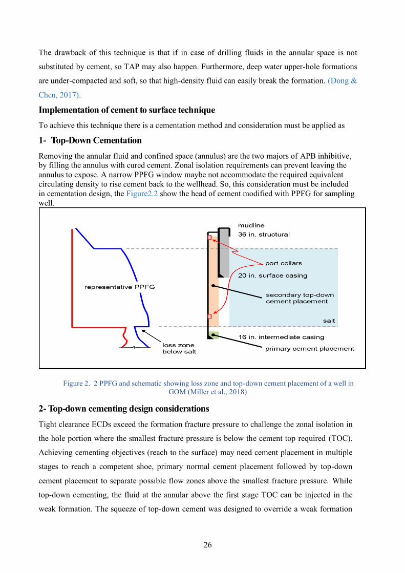
1- Top-Down Cementation Removing the annular fluid and confined space (annulus) are the two majors of APB inhibitive, by filling the annulus with cured cement. Zonal isolation requirements can prevent leaving the annulus to expose. A narrow PPFG window maybe not accommodate the required equivalent circulating density to rise cement back to the wellhead. So, this consideration must be included in cementation design, the Figure2.2 show the head of cement modified with PPFG for sampling well.
Figure 2. 2 PPFG and schematic showing loss zone and top-down cement placement of a well in
GOM (Miller et al., 2018)
2- Top-down cementing design considerations Tight clearance ECDs exceed the formation fracture pressure to challenge the zonal isolation in
the hole portion where the smallest fracture pressure is below the cement top required (TOC).
Achieving cementing objectives (reach to the surface) may need cement placement in multiple
stages to reach a competent shoe, primary normal cement placement followed by top-down
cement placement to separate possible flow zones above the smallest fracture pressure. While
top-down cementing, the fluid at the annular above the first stage TOC can be injected in the
weak formation. The squeeze of top-down cement was designed to override a weak formation
27
fracture pressure in the open hole, which is specified during well planning. In case there is a
potential of flow zones at the place proximity to the weak formation, there might be a lack of
certainty as to which zone will take losses. this design scenario would raise the importance of
setting the first stage cement top at, or just beneath, the upper DPZ. Unlike primary cementing
where gravity tends to sustain the heavier slurry beneath the mud while annular placement,
gravity tends to promote a heavier slurry to channel through a lighter mud. Controlling and
designing rheological properties improve cementing operation to achieve the best result of
cementation. as shown in Table 2.1 the difference between conventional and top-down stages of
the cement slurry. Some top-down cement placement benefits from preparing cement with more
than two formulations with different thickening times as an operating condition required (Miller
et al., 2018). This method (cement shortfall) could cost a lot and take more time for application.
Table 2. 1 Density and rheological hierarchy for the two cement stages (Miller et al., 2018)
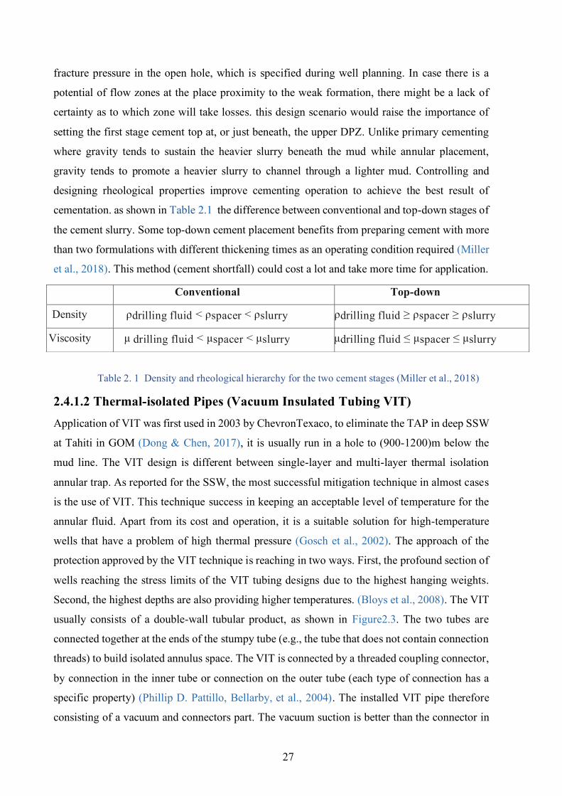
2.4.1.2 Thermal-isolated Pipes (Vacuum Insulated Tubing VIT) Application of VIT was first used in 2003 by ChevronTexaco, to eliminate the TAP in deep SSW
at Tahiti in GOM (Dong & Chen, 2017), it is usually run in a hole to (900-1200)m below the
mud line. The VIT design is different between single-layer and multi-layer thermal isolation
annular trap. As reported for the SSW, the most successful mitigation technique in almost cases
is the use of VIT. This technique success in keeping an acceptable level of temperature for the
annular fluid. Apart from its cost and operation, it is a suitable solution for high-temperature
wells that have a problem of high thermal pressure (Gosch et al., 2002). The approach of the
protection approved by the VIT technique is reaching in two ways. First, the profound section of
wells reaching the stress limits of the VIT tubing designs due to the highest hanging weights.
Second, the highest depths are also providing higher temperatures. (Bloys et al., 2008). The VIT
usually consists of a double-wall tubular product, as shown in Figure2.3. The two tubes are
connected together at the ends of the stumpy tube (e.g., the tube that does not contain connection
threads) to build isolated annulus space. The VIT is connected by a threaded coupling connector,
by connection in the inner tube or connection on the outer tube (each type of connection has a
specific property) (Phillip D. Pattillo, Bellarby, et al., 2004). The installed VIT pipe therefore
consisting of a vacuum and connectors part. The vacuum suction is better than the connector in
Conventional Top-down
Density ρdrilling fluid < ρspacer < ρslurry ρdrilling fluid ≥ ρspacer ≥ ρslurry
Viscosity μ drilling fluid < μspacer < μslurry μdrilling fluid ≤ μspacer ≤ μslurry
28
the isolating effect, especially when the connector is not well insulated (Kang et al., 2017).
Thermal-isolated pipes contain two walls and one inter-layer. commonly, the inter-layer is
vacuum or stuffed with thermally isolated materials such as high-yield point fluid, viscous fluid,
or just with light cement to increase the radial thermal strength. The expected lowest annular
pressure is found when both setting depths are the top of the cement of annular ‘B’. This tells
that the best setting depth is the depth of TOC of annular ‘B’. This is because the annulus radial
heat inhibition will no longer be improved in the case of setting depth override TOC. To reach
mitigation demand, thermal-isolated production casing and tubing can be used at the same well
(Figure 2.4combination.2) or isolation tubing only (Figure 2.4 combination.1). To reduce the cost
associated with operational, engineering, and suppling, VIT is always applied in combination
with ordinary tubing. The VIT string is run from the midline to a strategically chosen point,
below which ordinary tubing is applied. The setting depth, heat influxes, and the combination
can be decided by numerical simulations of the wellbore and experimental methods or both. VIT
tubes increase overall well cost and in limited equipping, also “cold-worked corrosion-resistant
alloy (CRA) materials” are incompatible with the welding operations (Payne et al., 2007).
Figure 2. 3 Typical VIT schematic with connection on the outer tube (Kang et al., 2017)
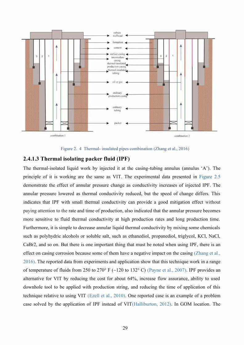
29
Figure 2. 4 Thermal- insulated pipes combination (Zhang et al., 2016)
2.4.1.3 Thermal isolating packer fluid (IPF) The thermal-isolated liquid work by injected it at the casing-tubing annulus (annulus ‘A’). The
principle of it is working are the same as VIT. The experimental data presented in Figure 2.5
demonstrate the effect of annular pressure change as conductivity increases of injected IPF. The
annular pressure lowered as thermal conductivity reduced, but the speed of change differs. This
indicates that IPF with small thermal conductivity can provide a good mitigation effect without
paying attention to the rate and time of production, also indicated that the annular pressure becomes
more sensitive to fluid thermal conductivity at high production rates and long production time.
Furthermore, it is simple to decrease annular liquid thermal conductivity by mixing some chemicals
such as polyhydric alcohols or soluble salt, such as ethanediol, propanediol, triglycol, KCl, NaCl,
CaBr2, and so on. But there is one important thing that must be noted when using IPF, there is an
effect on casing corrosion because some of them have a negative impact on the casing (Zhang et al.,
2016). The reported data from experiments and application show that this technique work in a range
of temperature of fluids from 250 to 270° F (~120 to 132° C) (Payne et al., 2007). IPF provides an
alternative for VIT by reducing the cost for about 64%, increase flow assurance, ability to used
downhole tool to be applied with production string, and reducing the time of application of this
technique relative to using VIT (Ezell et al., 2010). One reported case is an example of a problem
case solved by the application of IPF instead of VIT(Halliburton, 2012). In GOM location. The
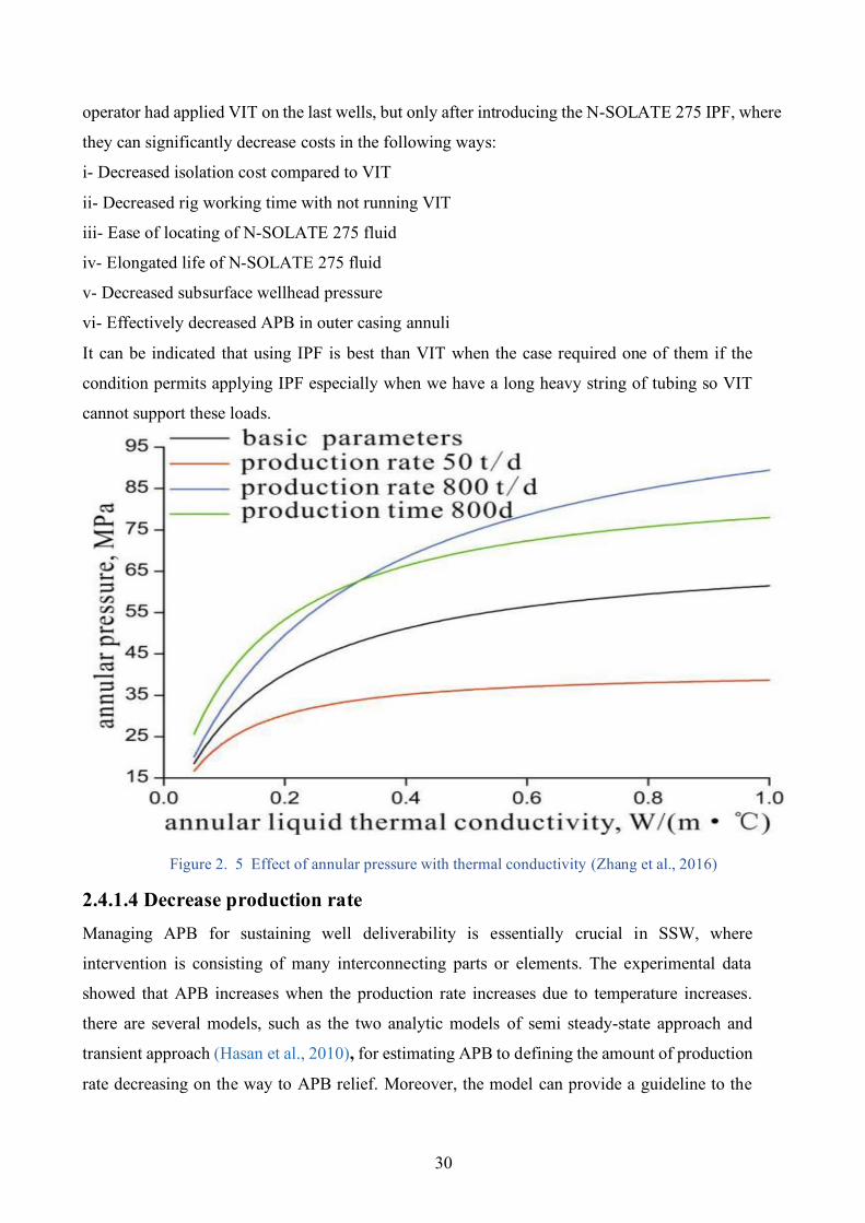
30
operator had applied VIT on the last wells, but only after introducing the N-SOLATE 275 IPF, where
they can significantly decrease costs in the following ways:
i- Decreased isolation cost compared to VIT
ii- Decreased rig working time with not running VIT
iii- Ease of locating of N-SOLATE 275 fluid
iv- Elongated life of N-SOLATE 275 fluid
v- Decreased subsurface wellhead pressure
vi- Effectively decreased APB in outer casing annuli
It can be indicated that using IPF is best than VIT when the case required one of them if the
condition permits applying IPF especially when we have a long heavy string of tubing so VIT
cannot support these loads.
Figure 2. 5 Effect of annular pressure with thermal conductivity (Zhang et al., 2016)
2.4.1.4 Decrease production rate Managing APB for sustaining well deliverability is essentially crucial in SSW, where
intervention is consisting of many interconnecting parts or elements. The experimental data
showed that APB increases when the production rate increases due to temperature increases.
there are several models, such as the two analytic models of semi steady-state approach and
transient approach (Hasan et al., 2010), for estimating APB to defining the amount of production
rate decreasing on the way to APB relief. Moreover, the model can provide a guideline to the
31
operators on the amount of venting volume required to get a better operable domain of production
rate. Estimation of APB and bleed volume help to improve the methodology applied, for
diagnosis and mitigation together. This method useful in case of the presence of TAP for
production well that has not to design mitigation or to support the insufficient designed
mitigation, but not suggested to decrease the production rate for the new design, so selecting
another mitigation device is the best for new well design.
2.4.2 Passive mitigation methods This type of mitigation technique is activated after the generation of TAP, these techniques are
principled on venting APB, provide extra space for expanded volume, relief of the APB, and
improve annulus properties to accept extra APB.
1-Cement shortfall Provide a natural or pressurized fracturing venting way for the fluid pressure to bleed into
formation by leaving TOC under the previous casing shoe to leak into formation in case of annular
pressure is high enough.
2- Using high compressibility fluid Increase the compressibility of the trapped fluid makes the final Annular pressure lower through
increasing confined system compressibility (Loder et al., 2003).
3- Pressure Relief It is the classical category of techniques that is the bulk. It contains the following techniques:
valves to the atmosphere, hole at the wellhead with ROV, rupture disk, casing perforation, and
Annular pressure relief collar (Santos et al., 2015), (Dong & Chen, 2017).
4- Compressible foam Using a Foam placed on the casing outside surface will be compressed when pressure increased
and absorb the APB also can be titled under the means of increasing confined system
compressibility.
5- Casing structural strength increases Increasing casing physical properties to increase loads (collapse and burst) integrity (Leach &
Adams, 1993).
6- Mitigation casing Using special casing type contain space and valve to accommodate the extra volume due to
trapped fluid expansion.
32
7- Additional chamber Similar to the mitigation casing but in this type the casing is supplied with a chamber and
valve placed at the casing as accessories (Dong & Chen, 2017).
8- Sacrificial casing Design a multi-string casing with a pointed weak point of the casing to damage at TAP and
protect the other part of the annulus. 2.4.2.1 Cement shortfall This technique based and restricted by formation properties also can cause some other potential
risk. This technique may be impacted by cement channelling due to the poor mud displacement
caused by bad casing cantering or weak erodibility of the fluid at the wellbore in primary
cementing operation. Besides, trapped pressure can happen when there is a barite sag* occurred
following drilling operations or when the completion fluid is set in the annulus (Calçada et al.,
2016). In most cases, SSW is not completed directly after finishing the drilling operation due to
the time required for other components of the production infrastructure (Vargo et al., 2002). A
long time can lead to settling of the weighting agent of annulus fluid and cause plugging in the
exposed formation, this problem restricted cement shortfall technique. Mathematical models and
experimental data were applied to design rheological properties of sealing fluids to control barite
sage (Calcada et al., 2017).
2.4.2.1.1 Application of cement shortfall (Open shoe) technique It should be noted that, even with the open shoe, problems will occur on formations with high
fracture gradient or in section opened in salt formations. It cannot be applied in wells that have
permeable zones that require isolation at the section of the few meters below the shoe. In these
cases, the formation must be cemented, and a confined annulus is required for design
considerations, the formation is considered to fracture when the pressure exceeds the (Pf) fracture
gradient at depth (Hf). In this design, an important argument is that the gradient of fracture is not
a deterministic feature. Rather, it's a set of values where failure may occur. Geomechanically
studies conducted for shoe setting usually consider the lowest value that can cause the failure (Pf
mini). On the other hand, for an APB analysis, it is suggested to use the highest value the shoe
should be able to withstand (Pf max), with a certain degree of confidence. In other words, (Pf = Pf
max) should be used from the geomechanically studies. Naturally, the probability distribution
function f(Pf) must be applied when performing a probabilistic design. With this value at hand,
it should be tested if casings can withstand collapse and burst loads before shoe fracture.
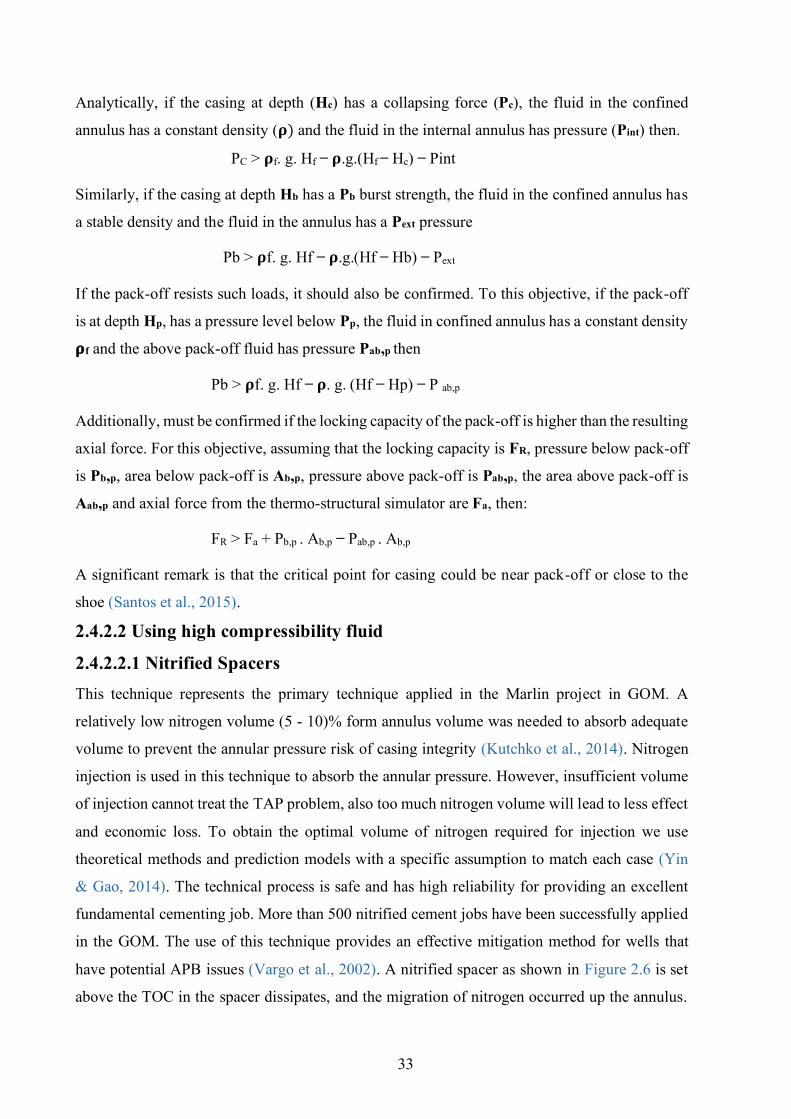
33
Analytically, if the casing at depth (Hc) has a collapsing force (Pc), the fluid in the confined
annulus has a constant density (𝛒) and the fluid in the internal annulus has pressure (Pint) then.
PC > 𝛒f. g. Hf ̶ 𝛒.g.(Hf ̶ Hc) ̶ Pint
Similarly, if the casing at depth Hb has a Pb burst strength, the fluid in the confined annulus has
a stable density and the fluid in the annulus has a Pext pressure
Pb > 𝛒f. g. Hf ̶ 𝛒.g.(Hf ̶ Hb) ̶ Pext
If the pack-off resists such loads, it should also be confirmed. To this objective, if the pack-off
is at depth Hp, has a pressure level below Pp, the fluid in confined annulus has a constant density
𝛒f and the above pack-off fluid has pressure Pab,p then
Pb > 𝛒f. g. Hf ̶ 𝛒. g. (Hf ̶ Hp) ̶ P ab,p
Additionally, must be confirmed if the locking capacity of the pack-off is higher than the resulting
axial force. For this objective, assuming that the locking capacity is FR, pressure below pack-off
is Pb,p, area below pack-off is Ab,p, pressure above pack-off is Pab,p, the area above pack-off is
Aab,p and axial force from the thermo-structural simulator are Fa, then:
FR > Fa + Pb,p . Ab,p ̶ Pab,p . Ab,p
A significant remark is that the critical point for casing could be near pack-off or close to the
shoe (Santos et al., 2015).
2.4.2.2 Using high compressibility fluid
2.4.2.2.1 Nitrified Spacers This technique represents the primary technique applied in the Marlin project in GOM. A
relatively low nitrogen volume (5 - 10)% form annulus volume was needed to absorb adequate
volume to prevent the annular pressure risk of casing integrity (Kutchko et al., 2014). Nitrogen
injection is used in this technique to absorb the annular pressure. However, insufficient volume
of injection cannot treat the TAP problem, also too much nitrogen volume will lead to less effect
and economic loss. To obtain the optimal volume of nitrogen required for injection we use
theoretical methods and prediction models with a specific assumption to match each case (Yin
& Gao, 2014). The technical process is safe and has high reliability for providing an excellent
fundamental cementing job. More than 500 nitrified cement jobs have been successfully applied
in the GOM. The use of this technique provides an effective mitigation method for wells that
have potential APB issues (Vargo et al., 2002). A nitrified spacer as shown in Figure 2.6 is set
above the TOC in the spacer dissipates, and the migration of nitrogen occurred up the annulus.
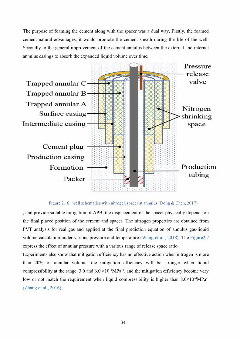
34
The purpose of foaming the cement along with the spacer was a dual way. Firstly, the foamed
cement natural advantages, it would promote the cement sheath during the life of the well.
Secondly to the general improvement of the cement annulus between the external and internal
annulus casings to absorb the expanded liquid volume over time,
Figure 2. 6 well schematics with nitrogen spacer at annulus (Dong & Chen, 2017)
, and provide suitable mitigation of APB, the displacement of the spacer physically depends on
the final placed position of the cement and spacer. The nitrogen properties are obtained from
PVT analysis for real gas and applied at the final prediction equation of annulus gas-liquid
volume calculation under various pressure and temperature (Wang et al., 2018). The Figure2.7
express the effect of annular pressure with a various range of release space ratio.
Experiments also show that mitigation efficiency has no effective action when nitrogen is more
than 20% of annular volume, the mitigation efficiency will be stronger when liquid
compressibility at the range 3.0 and 6.0 ×10⁻⁴MPa-1, and the mitigation efficiency become very
low or not match the requirement when liquid compressibility is higher than 8.0×10⁻⁴MPa-1
(Zhang et al., 2016).
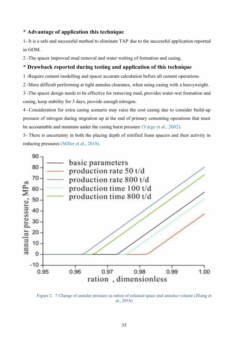
35
* Advantage of application this technique 1- It is a safe and successful method to eliminate TAP due to the successful application reported
in GOM.
2 - The spacer improved mud removal and water wetting of formation and casing.
* Drawback reported during testing and application of this technique 1 - Require cement modelling and spacer accurate calculation before all cement operations.
2 - More difficult performing at tight annulus clearance, when using casing with a heavyweight.
3 - The spacer design needs to be effective for removing mud, provides water-wet formation and
casing, keep stability for 3 days, provide enough nitrogen.
4 - Consideration for extra casing scenario may raise the cost casing due to consider build-up
pressure of nitrogen during migration up at the end of primary cementing operations that must
be accountable and maintain under the casing burst pressure (Vargo et al., 2002).
5- There is uncertainty in both the placing depth of nitrified foam spacers and their activity in
reducing pressures (Miller et al., 2018).
Figure 2. 7 Change of annular pressure as ration of released space and annulus volume (Zhang et al., 2016)
36
2.4.2.2.2 Water-Based Spacer (Fluid That Shrinks) The water-based spacer is a modern solution that has been developed to mitigate APB with
moderate to low range and can only be used ahead of the cement. During polymerization, the
MMA phase volume shrinks by 20%, providing space for the residual fluid to extend thermally
but without creating dangerous and destructive pressure. The polymerization activated by heat
and the target temperature can be controlled by selecting the suitable chemical initiator type and
concentration. early polymerization of the placement of spacer can be avoided by a suitable type
and quantity, of inhibitor. A spacer formation (viscosifier, emulsifiers, MMA, weighting
materials, inhibitor, etc.) is improved which provides the range of densities that can be expected
in deep water wells conditions. To obtain the types and amounts of initiator and inhibitor required
to change the polymerization temperature to the range of temperatures anticipated in the field, a
matrix of benchtop tests is applied. These findings were verified in an advanced PVT cell that
simulates the downhole conditions closely. Safe handling procedures for mud plant preparation,
transportation, and application of rig sites were developed. This mitigation method is cheaper
than nitrogen spacer, crushable foam, and VIT.
2.4.2.2.3 Drilling fluids Spacer In some cases, the drilling fluid that lifted in the annulus can help to reduce the effect of TAP
when it was low and not need to use other costed mitigation methods. The mud properties were
improved to be the mitigation device for APB. There are some recommendations obtained by
experimental results and model approaches show that compressive yield stress, variance in
density between the solid and liquid phases of drilling fluid, practical size of solid and annular
space geometry, are four essential parameters that locate the rate of sedimentation. These criteria
are used to describe YPL annular fluid properties to minimize sedimentation rate and
consequently to minimize free convective flow, this approach applied to analyse the reliability
and sustainability of the isolating activity of drilling fluids (Ettehadi Osgouei, R., 2014). This
technique applied for wells with relatively low to moderate APB (to the permissible limit). When
there is one design scenario of a very low probability (risk level) threat the casing by TAP and
can be treated by this mitigation method.
2.4.2.3 Pressure relief device
2.4.2.3.1 Valves to the atmosphere Although it is confined to onshore and dry wells of completion (Santos et al., 2015), the technique
is listed here, as it is the most common technique in those situations. It consists of venting the
trapped pressure from the trapped annulus directly by a venting device at the wellhead. Therefore,
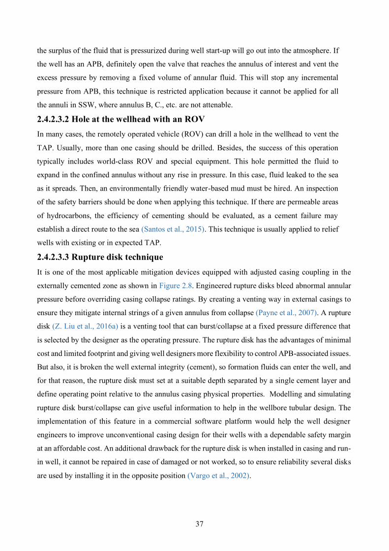
37
the surplus of the fluid that is pressurized during well start-up will go out into the atmosphere. If
the well has an APB, definitely open the valve that reaches the annulus of interest and vent the
excess pressure by removing a fixed volume of annular fluid. This will stop any incremental
pressure from APB, this technique is restricted application because it cannot be applied for all
the annuli in SSW, where annulus B, C., etc. are not attenable.
2.4.2.3.2 Hole at the wellhead with an ROV In many cases, the remotely operated vehicle (ROV) can drill a hole in the wellhead to vent the
TAP. Usually, more than one casing should be drilled. Besides, the success of this operation
typically includes world-class ROV and special equipment. This hole permitted the fluid to
expand in the confined annulus without any rise in pressure. In this case, fluid leaked to the sea
as it spreads. Then, an environmentally friendly water-based mud must be hired. An inspection
of the safety barriers should be done when applying this technique. If there are permeable areas
of hydrocarbons, the efficiency of cementing should be evaluated, as a cement failure may
establish a direct route to the sea (Santos et al., 2015). This technique is usually applied to relief
wells with existing or in expected TAP.
2.4.2.3.3 Rupture disk technique It is one of the most applicable mitigation devices equipped with adjusted casing coupling in the
externally cemented zone as shown in Figure 2.8. Engineered rupture disks bleed abnormal annular
pressure before overriding casing collapse ratings. By creating a venting way in external casings to
ensure they mitigate internal strings of a given annulus from collapse (Payne et al., 2007). A rupture
disk (Z. Liu et al., 2016a) is a venting tool that can burst/collapse at a fixed pressure difference that
is selected by the designer as the operating pressure. The rupture disk has the advantages of minimal
cost and limited footprint and giving well designers more flexibility to control APB-associated issues.
But also, it is broken the well external integrity (cement), so formation fluids can enter the well, and
for that reason, the rupture disk must set at a suitable depth separated by a single cement layer and
define operating point relative to the annulus casing physical properties. Modelling and simulating
rupture disk burst/collapse can give useful information to help in the wellbore tubular design. The
implementation of this feature in a commercial software platform would help the well designer
engineers to improve unconventional casing design for their wells with a dependable safety margin
at an affordable cost. An additional drawback for the rupture disk is when installed in casing and run-
in well, it cannot be repaired in case of damaged or not worked, so to ensure reliability several disks
are used by installing it in the opposite position (Vargo et al., 2002).
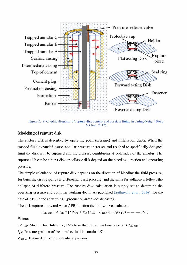
38
Figure 2. 8 Graphic diagrams of rupture disk content and possible fitting in casing design (Dong & Chen, 2017)
Modeling of rupture disk The rupture disk is described by operating point (pressure) and installation depth. When the
trapped fluid expanded cause, annular pressure increases and reached to specifically designed
limit the disk will be ruptured and the pressure equilibrium at both sides of the annulus. The
rupture disk can be a burst disk or collapse disk depend on the bleeding direction and operating
pressure.
The simple calculation of rupture disk depends on the direction of bleeding the fluid pressure,
for burst the disk responds to differential burst pressure, and the same for collapse it follows the
collapse of different pressure. The rupture disk calculation is simply set to determine the
operating pressure and optimum working depth. As published (Sathuvalli et al., 2016), for the
case of APB in the annulus ‘X’ (production-intermediate casing).
The disk ruptured outward when APB function the following calculations
PBD nom ± ∆PBD = [∆PAPB + ƔX (ZBD – Z ref,X)] – Pe (ZBD) -----------(2-1)
Where:
±∆PBD: Manufacture tolerance, ±5% from the normal working pressure (PBD nom).
ƔR: Pressure gradient of the annulus fluid in annulus ‘X’.
Z ref, X: Datum depth of the calculated pressure.
39
Pe: Fracture strength of the formation at the depth of setting disk.
ZBD: Depth of rupture disk.
The APB for activating the disk can be determined by
APB min ≤ APB ≤ APB max -------------(2-2)
APB min = {(PBD - ∆PBD) + [Pe(ZBD)]min – ƔX (ZBD – Z ref,X)} --------(2-3)
APB max = {(PBD - ∆PBD) + [Pe(ZBD)]max – ƔX (ZBD – Z ref,X)} --------(2-4)
Then define Z coll as the depth of most collapse can happen due to differential pressure effect in
a given annulus (B), the maximum collapse pressure due to differential pressure in the inner
annulus can be determined by
∆Pcoll = {∆PAPB + ƔX (Zcoll – Z ref,X)} - {(1- 2𝑡
𝑑𝑜)ƔL (Zcoll – Z ref,L)} ----(2-5)
Where:
t/do: is the diameter-wall thickness ration of the inner annulus.
ƔL: is the gradient of a given annulus (X) hydrostatic pressure of the liquid.
Z ref, L: is the datum depth of the calculated pressure (these depths are changed for every
annulus).
In order to protect the annulus from collapse, the following relation must be proved
∆Pcoll ≤ ∆Pcoll, max
∆Pcoll, max = {∆PAPB,max + ƔX (Zcoll,max – Z ref,X)} - {(1- 2𝑡
𝑑𝑜)ƔL (Zcoll,max – Z ref,L)}--------(2-6)
To perfectly protect annulus from collapse the following situation must be confirmed
∆Pcoll, max ≤ DFcoll, Pc ------------(2-7)
Where:
Pc: collapse working pressure for inside givin annulus string (adjusted by temperature).
DFcoll, Pc: design factor of collapse rating.
To ensure that the APB never overcome the allowable APB limit, the following situation must
be confirmed
∆PAPB, MAX ≤ ∆Pallow ------------(2-8)
When the disk operating pressure is selected, the effect of drilling loads to the casing is not
influenced, so the equation (2-9) is written as
PAPI,MYIP ˂ PBD - ∆PBD ˂ PBD + ∆PBD ˂ PRupture -------(2-9)
Where:
PAPI, MYIP: Physical properties of pressure strength for the selected casing
40
PRupture : Rupture limit of the selected casing.
The equations (2-1----2-9) are applied repeatedly to reach suitable disk depth and operating
pressure.
2.4.2.3.4 Casing perforation In this technique, a perforation device is set in the hole after running the casing in front of the
problematic part of the annulus and the outer casing is perforated. In most cases, this technique
treats the problem of TAP, but it may cost high, based on the depth of perforated casing as
required. If this depth is too shallow, the exposed formation maybe cannot resist the pressure
gradient of the fluid, and fracture may accrue. A liner and tie-back configuration become
necessary to be used in this case, to prevent an underground blowout. Since running liner and tie-
back generally takes longer than the running casing, costs increase significantly. A negative
pressure test should be applied after installation of the liner and before perforation of the casing,
to evaluate the hydraulic isolation of the cement interference. Then, the perforation job can be
performed safely.
The design procedures (Santos et al., 2015) are similar to the open shoe one. Casing collapse and
burst loads integrity, until fracture at the perforation, should be verified. Analytically, if the
casing at depth Hc has a collapse resistance Pc, the density of the confined fluid in the annulus is
constant 𝛒 and the pressure of the fluid in the internal annulus is Pint then
In the same way, if the depth of casing is Hb has a burst resistance Pb, the density of the fluid in
the confined annulus is constant 𝛒 and the fluid pressure in the internal annulus is Pext then:
Also, pack-off should be verified resists to these efforts. For that reason, assuming that the depth
of
pack-off is Hp, and its strength is Pp, the density of the fluid in the confined annulus is constant
𝛒 and the pressure of the fluid above the pack-off is Pab, p, then:
Besides, a significant note is that the critical position for casing can be near pack-off or shoe.
2.4.2.3.5 Relief collar for annular pressure This technique (Dong & Chen, 2017) was first applied to mitigate deep-water TAP by
Halliburton in 2004. The device can be turned ON and OFF frequently on the internal casing of
the annular trap to transmit surplus pressure to the annulus ‘A’. Then the pressure vented for
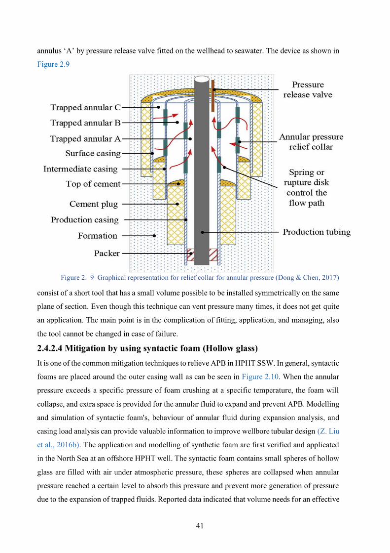
41
annulus ‘A’ by pressure release valve fitted on the wellhead to seawater. The device as shown in
Figure 2.9
Figure 2. 9 Graphical representation for relief collar for annular pressure (Dong & Chen, 2017)
consist of a short tool that has a small volume possible to be installed symmetrically on the same
plane of section. Even though this technique can vent pressure many times, it does not get quite
an application. The main point is in the complication of fitting, application, and managing, also
the tool cannot be changed in case of failure.
2.4.2.4 Mitigation by using syntactic foam (Hollow glass) It is one of the common mitigation techniques to relieve APB in HPHT SSW. In general, syntactic
foams are placed around the outer casing wall as can be seen in Figure 2.10. When the annular
pressure exceeds a specific pressure of foam crushing at a specific temperature, the foam will
collapse, and extra space is provided for the annular fluid to expand and prevent APB. Modelling
and simulation of syntactic foam's, behaviour of annular fluid during expansion analysis, and
casing load analysis can provide valuable information to improve wellbore tubular design (Z. Liu
et al., 2016b). The application and modelling of synthetic foam are first verified and applicated
in the North Sea at an offshore HPHT well. The syntactic foam contains small spheres of hollow
glass are filled with air under atmospheric pressure, these spheres are collapsed when annular
pressure reached a certain level to absorb this pressure and prevent more generation of pressure
due to the expansion of trapped fluids. Reported data indicated that volume needs for an effective
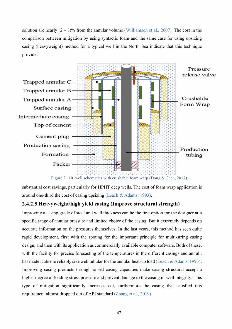
42
solution are nearly (2 – 8)% from the annular volume (Williamson et al., 2007). The cost in the
comparison between mitigation by using syntactic foam and the same case for using upsizing
casing (heavyweight) method for a typical well in the North Sea indicate that this technique
provides
Figure 2. 10 well schematics with crushable foam warp (Dong & Chen, 2017)
substantial cost savings, particularly for HPHT deep wells. The cost of foam wrap application is
around one-third the cost of casing upsizing (Leach & Adams, 1993).
2.4.2.5 Heavyweight/high yield casing (Improve structural strength) Improving a casing grade of steel and wall thickness can be the first option for the designer at a
specific range of annular pressure and limited choice of the casing. But it extremely depends on
accurate information on the pressures themselves. In the last years, this method has seen quite
rapid development, first with the rooting for the important principle for multi-string casing
design, and then with its application as commercially available computer software. Both of these,
with the facility for precise forecasting of the temperatures in the different casings and annuli,
has made it able to reliably size well tubular for the annular heat-up load (Leach & Adams, 1993).
Improving casing products through raised casing capacities make casing structural accept a
higher degree of loading stress pressure and prevent damage to the casing or well integrity. This
type of mitigation significantly increases cot, furthermore the casing that satisfied this
requirement almost dropped out of API standard (Zhang et al., 2019).
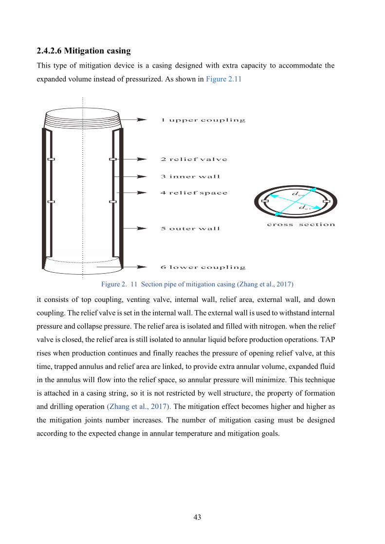
43
2.4.2.6 Mitigation casing This type of mitigation device is a casing designed with extra capacity to accommodate the
expanded volume instead of pressurized. As shown in Figure 2.11
Figure 2. 11 Section pipe of mitigation casing (Zhang et al., 2017)
it consists of top coupling, venting valve, internal wall, relief area, external wall, and down
coupling. The relief valve is set in the internal wall. The external wall is used to withstand internal
pressure and collapse pressure. The relief area is isolated and filled with nitrogen. when the relief
valve is closed, the relief area is still isolated to annular liquid before production operations. TAP
rises when production continues and finally reaches the pressure of opening relief valve, at this
time, trapped annulus and relief area are linked, to provide extra annular volume, expanded fluid
in the annulus will flow into the relief space, so annular pressure will minimize. This technique
is attached in a casing string, so it is not restricted by well structure, the property of formation
and drilling operation (Zhang et al., 2017). The mitigation effect becomes higher and higher as
the mitigation joints number increases. The number of mitigation casing must be designed
according to the expected change in annular temperature and mitigation goals.
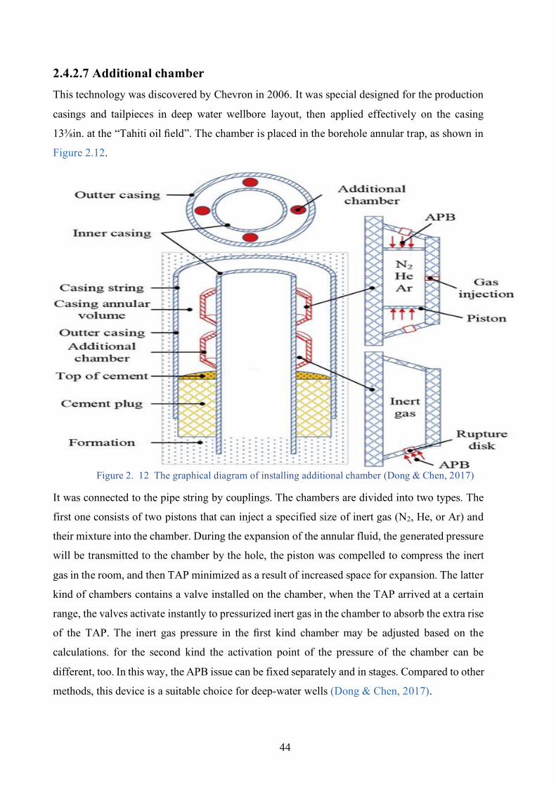
44
2.4.2.7 Additional chamber This technology was discovered by Chevron in 2006. It was special designed for the production
casings and tailpieces in deep water wellbore layout, then applied effectively on the casing
13⅜in. at the “Tahiti oil field”. The chamber is placed in the borehole annular trap, as shown in
Figure 2.12.
Figure 2. 12 The graphical diagram of installing additional chamber (Dong & Chen, 2017)
It was connected to the pipe string by couplings. The chambers are divided into two types. The
first one consists of two pistons that can inject a specified size of inert gas (N2, He, or Ar) and
their mixture into the chamber. During the expansion of the annular fluid, the generated pressure
will be transmitted to the chamber by the hole, the piston was compelled to compress the inert
gas in the room, and then TAP minimized as a result of increased space for expansion. The latter
kind of chambers contains a valve installed on the chamber, when the TAP arrived at a certain
range, the valves activate instantly to pressurized inert gas in the chamber to absorb the extra rise
of the TAP. The inert gas pressure in the first kind chamber may be adjusted based on the
calculations. for the second kind the activation point of the pressure of the chamber can be
different, too. In this way, the APB issue can be fixed separately and in stages. Compared to other
methods, this device is a suitable choice for deep-water wells (Dong & Chen, 2017).
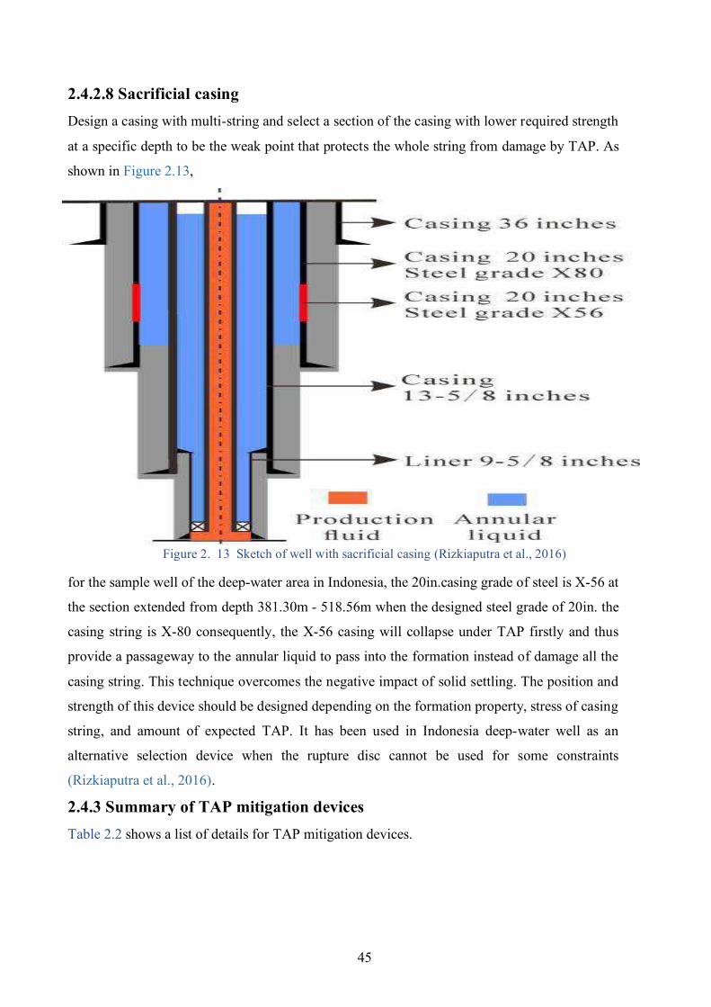
45
2.4.2.8 Sacrificial casing Design a casing with multi-string and select a section of the casing with lower required strength
at a specific depth to be the weak point that protects the whole string from damage by TAP. As
shown in Figure 2.13,
Figure 2. 13 Sketch of well with sacrificial casing (Rizkiaputra et al., 2016)
for the sample well of the deep-water area in Indonesia, the 20in.casing grade of steel is X-56 at
the section extended from depth 381.30m - 518.56m when the designed steel grade of 20in. the
casing string is X-80 consequently, the X-56 casing will collapse under TAP firstly and thus
provide a passageway to the annular liquid to pass into the formation instead of damage all the
casing string. This technique overcomes the negative impact of solid settling. The position and
strength of this device should be designed depending on the formation property, stress of casing
string, and amount of expected TAP. It has been used in Indonesia deep-water well as an
alternative selection device when the rupture disc cannot be used for some constraints
(Rizkiaputra et al., 2016).
2.4.3 Summary of TAP mitigation devices Table 2.2 shows a list of details for TAP mitigation devices.
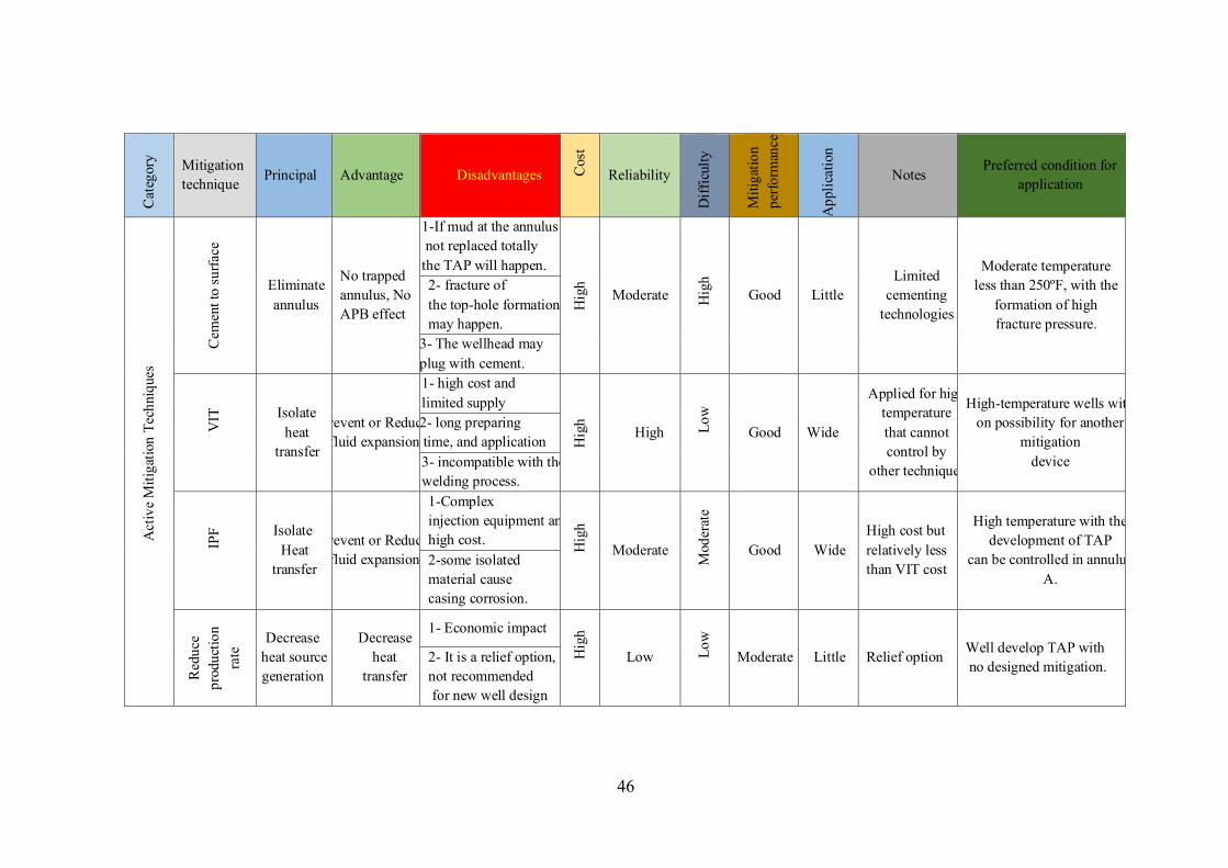
46
Cat
egor
y Mitigation technique Principal Advantage Disadvantages C
ost
Reliability
Diff
icul
ty
Miti
gatio
n pe
rform
ance
App
licat
ion
Notes Preferred condition for
application
Act
ive
Miti
gatio
n Te
chni
ques
Cem
ent t
o su
rface
Eliminate annulus
No trapped annulus, No APB effect
1-If mud at the annulus not replaced totally the TAP will happen.
Hig
h
Moderate Hig
h
Good Little Limited
cementing technologies
Moderate temperature less than 250ºF, with the
formation of high fracture pressure.
2- fracture of the top-hole formation may happen.
3- The wellhead may plug with cement.
VIT
Isolate heat
transfer
Prevent or Reduce fluid expansion
1- high cost and limited supply
Hig
h
High Low
Good Wide
Applied for high temperature that cannot control by
other techniques
High-temperature wells with on possibility for another
mitigation device
2- long preparing time, and application 3- incompatible with the welding process.
IPF Isolate
Heat transfer
Prevent or Reduce fluid expansion
1-Complex injection equipment and high cost. H
igh
Moderate
Mod
erat
e
Good Wide High cost but relatively less than VIT cost
High temperature with the development of TAP
can be controlled in annulus A.
2-some isolated material cause casing corrosion.
Red
uce
prod
uctio
n ra
te Decrease
heat source generation
Decrease heat
transfer
1- Economic impact
Hig
h
Low Low
Moderate Little Relief option Well develop TAP with no designed mitigation.
2- It is a relief option, not recommended for new well design
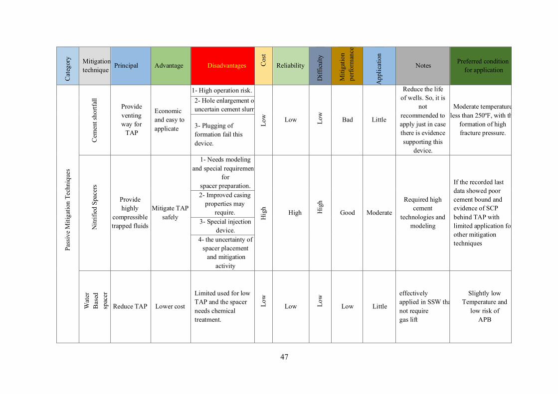
47
Cat
egor
y Mitigation technique
Principal Advantage Disadvantages Cos
t
Reliability
Diff
icul
ty
Miti
gatio
n pe
rform
ance
App
licat
ion
Notes Preferred condition for application
Pass
ive
Miti
gatio
n Te
chni
ques
Cem
ent s
hortf
all
Provide venting way for
TAP
Economic and easy to applicate
1- High operation risk.
Low
Low Low
Bad Little
Reduce the life of wells. So, it is
not recommended to apply just in case there is evidence supporting this
device.
Moderate temperature less than 250ºF, with the
formation of high fracture pressure.
2- Hole enlargement or uncertain cement slurry.
3- Plugging of formation fail this device.
Nitr
ified
Spa
cers
Provide highly
compressible trapped fluids
Mitigate TAP safely
1- Needs modeling and special requirements
for spacer preparation.
Hig
h
High Hig
h
Good Moderate
Required high cement
technologies and modeling
If the recorded last data showed poor cement bound and evidence of SCP behind TAP with limited application for other mitigation techniques
2- Improved casing properties may
require. 3- Special injection
device. 4- the uncertainty of
spacer placement and mitigation
activity
Wat
er
Bas
ed
spac
er
Reduce TAP Lower cost
Limited used for low TAP and the spacer needs chemical treatment.
Low
Low Low
Low Little
effectively applied in SSW that not require gas lift
Slightly low Temperature and
low risk of APB
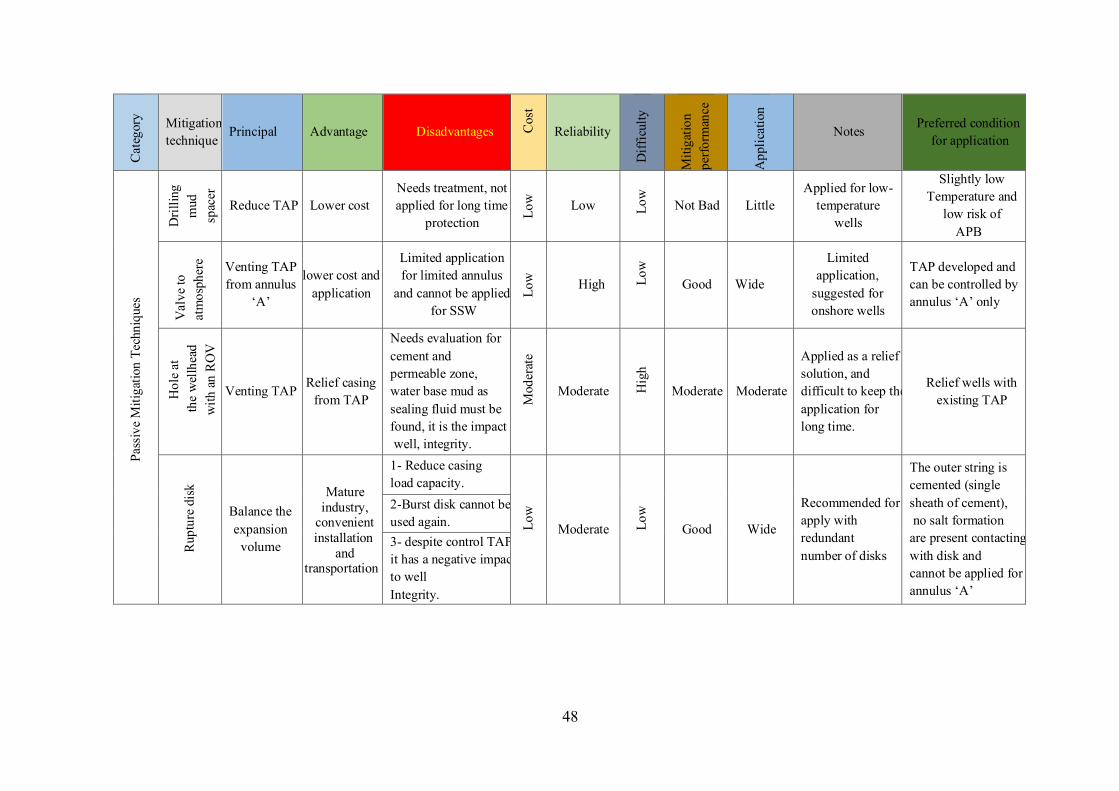
48
Cat
egor
y Mitigation technique
Principal Advantage Disadvantages Cos
t
Reliability
Diff
icul
ty
Miti
gatio
n pe
rform
ance
App
licat
ion
Notes Preferred condition for application
Pass
ive
Miti
gatio
n Te
chni
ques
Dril
ling
mud
sp
acer
Reduce TAP Lower cost
Needs treatment, not applied for long time
protection Low
Low Low
Not Bad Little Applied for low-
temperature wells
Slightly low Temperature and
low risk of APB
Val
ve to
at
mos
pher
e Venting TAP from annulus
‘A’
lower cost and application
Limited application for limited annulus
and cannot be applied for SSW
Low
High Low
Good Wide
Limited application,
suggested for onshore wells
TAP developed and can be controlled by annulus ‘A’ only
Hol
e at
th
e w
ellh
ead
w
ith a
n R
OV
Venting TAP Relief casing from TAP
Needs evaluation for cement and permeable zone, water base mud as sealing fluid must be found, it is the impact well, integrity.
Mod
erat
e
Moderate Hig
h
Moderate Moderate
Applied as a relief solution, and difficult to keep the application for long time.
Relief wells with existing TAP
Rup
ture
dis
k
Balance the expansion
volume
Mature industry,
convenient installation
and transportation
1- Reduce casing load capacity.
Low
Moderate Lo
w
Good Wide
Recommended for apply with redundant number of disks
The outer string is cemented (single sheath of cement), no salt formation are present contacting with disk and cannot be applied for annulus ‘A’
2-Burst disk cannot be used again. 3- despite control TAP, it has a negative impact to well Integrity.
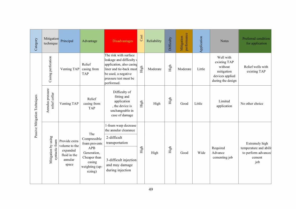
49
Cat
egor
y Mitigation technique
Principal Advantage Disadvantages Cos
t
Reliability
Diff
icul
ty
Miti
gatio
n pe
rform
ance
App
licat
ion
Notes Preferred condition
for application
Pass
ive
Miti
gatio
n Te
chni
ques
Cas
ing
perfo
ratio
n
Venting TAP Relief casing from TAP
The risk with surface leakage and difficulty of application, also casing liner and tie-back must be used, a negative pressure test must be performed.
Hig
h
Moderate Hig
h
Moderate Little
Well with existing TAP
without mitigation
devices applied during the design
Relief wells with existing TAP
Ann
ulus
pre
ssur
e re
lief c
olla
r
Venting TAP Relief
casing from TAP
Difficulty of fitting and application
, the device is unchangeable in case of damage
Hig
h
High Hig
h
Good Little Limited
application No other choice
M
itiga
tion
by u
sing
sy
ntac
tic fo
am
Provide extra volume to the
expanded fluid in the
annular space
The Compressible foam prevents
APB Generation,
Cheaper than casing
weighting (up-sizing)
1-foam warp decrease the annular clearance
Hig
h
High Hig
h
Good Wide Required Advance cementing job
Extremely high temperature and ability to perform advanced
cement job
2-difficult transportation
3-difficult injection and may damage during injection
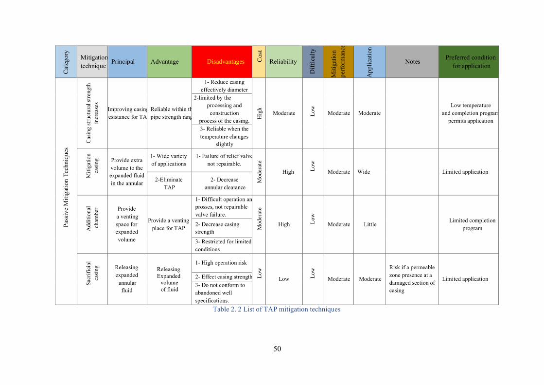
50
Cat
egor
y Mitigation technique
Principal Advantage Disadvantages Cos
t
Reliability
Diff
icul
ty
Miti
gatio
n pe
rform
ance
App
licat
ion
Notes Preferred condition for application
Pass
ive
Miti
gatio
n Te
chni
ques
Cas
ing
stru
ctur
al st
reng
th
incr
ease
s
Improving casing resistance for TAP
Reliable within the pipe strength range
1- Reduce casing effectively diameter
Hig
h
Moderate Low
Moderate Moderate Low temperature
and completion program permits application
2-limited by the processing and construction
process of the casing. 3- Reliable when the temperature changes
slightly
Miti
gatio
n ca
sing
Provide extra volume to the expanded fluid in the annular
1- Wide variety of applications
1- Failure of relief valve not repairable.
Mod
erat
e
High Low
Moderate Wide Limited application 2-Eliminate
TAP 2- Decrease
annular clearance
Add
ition
al
cha
mbe
r Provide a venting space for expanded volume
Provide a venting place for TAP
1- Difficult operation and prosses, not repairable valve failure.
Mod
erat
e
High Low
Moderate Little Limited completion
program 2- Decrease casing strength
3- Restricted for limited conditions
Sacr
ifici
al
casi
ng Releasing
expanded annular
fluid
Releasing Expanded volume of fluid
1- High operation risk Lo
w
Low Low
Moderate Moderate
Risk if a permeable zone presence at a damaged section of casing
Limited application 2- Effect casing strength 3- Do not conform to abandoned well specifications.
Table 2. 2 List of TAP mitigation techniques
51
2.5 Mitigation techniques for SCP Mitigation for this type of annular pressure is one of the more important issues due to the high
chance of happening for this problem. All types of wells either offshore or onshore for normal or
HPHT wells can sever from SCP, also the probability of this problem increased with the well
ages and in some cases can occur after well abandonment. The general concepts of SCP
mitigation are based on three ways (Bourgoyne et al., 2000)
1- Application of new practice and formulation of cementing.
2- Using of annular packer for the casing. 3- Internal pressure controlling during well life operations. These concepts can be applied as improvements during well design or as practices and
technologies during operations, as follow 2.5.1 Mitigation through well design When the possibility of SCP accruing is defining and addressed during well design constructions,
it is easier and best than future remediation operation. Identifying the possible influx from the
formation can lead to select an external packer or apply cement isolation for this formation. Also,
casing setting depths are set based on formation strength and kick tolerability. The probability of
crossflow between formations around casing is highly raised if the difference between formation
pressure gradient at the lower part of the section and the fracture gradient at the upper part of the
section is permitted to be very little value. The MMS set the minimum density margin between
shoe strength and density of mud provided to drill the section is 0.5 Ib/gal (Bourgoyne et al.,
2000) otherwise it will increase the chance of fluid channeling for in set cement. The construction
parameter of well design must be suitable for the expected conditions (temperature, pressure,
production rates…etc.) and take the effect of possible invaded fluid types such as H2S, water,
hydrocarbon…etc, and composition into account to set casing and wellhead resistivity to
corrosion and derating.
2.5.2 Mitigation by foamed spacer technology The use of traditional spacer technology has in many instances struggled to create a strong cement
bond. Foaming the spacer (Animesh Kumar et al., 2017) greatly increases its ability to displace
drilling mud and drill cuttings efficiently. Generally, the foamed spacer also has a higher yield
point (YP) that aids in the proper removal of mud. Furthermore, foaming will increase spacer
volume. The results of laboratory experiments and computer simulations demonstrate that the
foamed spacer has improved properties of rheological sweep performance compared to
traditional spacer fluid. The foamed spacer was successfully employed to increase drilling fluid
52
displacement and help to erode the partially dehydrated filter cake in the well. The design and
execution of the foamed spacer not only dramatically reduced the need for remediation of cement
work and lube-and-bleed activities for SCP remedial work, but also enabled the assessment of
cement bond and inter-zonal isolation. A full review for well design must be performed when the
well functionality is changed such as production well changed to injection or gas lifting applied
to the production well, also take the effect of transformed well to the vicinity wells.
2.5.3 Mitigation by applying cement pulsation method The idea (Wojtanowicz et al., 2002) starts by keeping the cement slurry at motion after placement
to control the gas migration by keeping the hydrostatic pressure of cement by using the cement
pulsation technique. This technology is applied first to control gas migration in Western Canada.
Gas or fluid flow through cement once it has been placed is mainly caused by the reduction of
hydrostatic pressure in the gas zone before the cement has built enough strength to stop gas flow.
In between these two events, the period is called the transition time, to prevent gas migration, it
is important to minimize the transition time of cement This technique involves performing low
frequency, hydraulic pressure pulse to the annulus from the wellhead directly after cement
placement. These pulses (about 550 kPa – 1,000 kPa) pressure pulses to the annulus with
frequencies of 30 to 60 seconds. It is applied instantly after stop pumping; the BOP’s are closed,
and the cement pulsation unit starts to perform pulses to the annulus through the surface casing
vent valve. The reported results showed that the pulses could be transferred as deep as 2,650
meters which permits full hydrostatic pressure to be transferred downhole in the gas area and
decrease the gel strength of cement slurry. This special technique utilizes low permeability
cement to avoids gas from entering into the slurry. Even though it was successful, it didn't
function uniformly in all areas (Dusterhoft et al., 2002) due to limited cement technologies,
control cement rheological properties with the condition of ambient, especially in some deep
wells.
To prevent gas migration and improve cementing operation to avoid forming micro annulus and
channels it is recommended to apply these some recommendations (Milanovic & Smith, 2005)
1- Fully deplete gas pockets encountered while drilling before cementing.
2- A “mud-filled external casing packer” should be run just above the zone of expected high
background gas (as part of the production casing string) if possible.
3- Displacement of cement, if operationally possible, should be done by a fluid of the same
density of the mud that will be used for the next hole section or the density of the brine to be
lifted in the annulus ‘A’ after well completion to minimize the micro annuli formation.
53
4- Losses must be treated and eliminate gas presence before starting cementing.
5- The cement design should be adapted to individual wells and considering events such as losses
and high background gas during the drilling process.
6- Using a high surplus amount of cement (Tahmourpour et al., 2010) to provide a sufficient
volume of pure cement and displaced with a high rate (as possible) with accurate displacement
volume.
7- Use of alternative cement types (Phi et al., 2019) such as sodium silicate activated slag/blended
with fly ash, Calcium aluminate phosphate, and foam cement instead of Portland cement that
shows a weak cement bond in XHPHT and geothermal wells due to degradation caused by acidic
environments and high temperature.
2.6 Review of remediation methods of SCP In case of well have an SCP there are a lot of technologies that can be applied as remediation
methods. One includes terminating the inner casing string and setting a cement plug. This
approach was recorded only if there is no cement sheath behind the inner casing. A further rig
technique is section milling, which implies milling of a casing portion and pumping cement to
inhibit gas flow. The key challenge for this technique was the complexity of standardizing the
size of the milling tool, where the inner casing is irregular in comparison with the outer casing.
Another cheap rig fewer methods are pumping killing mud in the annulus to kill the SCP and
increase the hydrostatic pressure above TOC or using sealant materials to plug the annulus. Rig-
less methods of SAP remediation encompass external remediation of the casing annulus
employing a collection of bleeding off the pressure and injecting a sealing/killing fluid either at
the wellhead (Bleed and Lube) or at depth through flexible tubing inserted into the annulus.
Another researches and experiments developed for this purpose by pumping down an alloy metal
that has a low-melting-point inside the SCP annulus and collecting this material above the cement
top then melting it with a heating instrument to make a ring plug, that prevents the fluid leakage
from the formation (Carpenter et al., 2004). Some of this remediation developed to used new
procedures and technologies, some of them applied by using rigs or rig less depending on the
size of the damage and associated risk (Milanovic & Smith, 2005). The diagnostic test analysis
and risk analysis plan provide the guide for analysing the problem and set a suitable remediation
plan.
1-Bleed-and-lube method We choose this method (Nishikawa et al., 2001) as an example of the best common remediation
methods and the lowest cost of all other remediation techniques. This technique represents the
54
displacing of fluid in the annulus by successive cycles of pressure expulsion by venting continued
with lubrication of small pits of killing fluid. In some cases, recorded some decrease in surface
casing pressures and mentioned that Zinc Bromide was partially effective when used as a kill
fluid, the reported cases show that decreasing pressure is not sufficient to control the SCP. Also,
the application of heavy killing mud or high pumping pressure may impact the weak point at the
shoe or any weak part at the annulus section and could open a new leaking path from intermediate
to production casing, this leaking path impact the analysis and technique goals to control SCP,
this technique applied by using heavy mud or brine, but the injection of brine into water-based
mud can create a plugin the upper part of the annulus that prevent complete displacement of the
volume required of the annulus. Furthermore, using brine with water can solve this problem but
need a lot of injection cycles to achieve the total annulus displacement. The annulus fluid analysis
is the key to decide the type of killing fluid and displacement. The immiscible gravity
displacement of annular fluid applied with immiscible kill fluids by highest density, friction
coefficient, and interfacial tension, displaced in the minimum time is the cheapest and effective
one for application on this technique for eliminating the SCP.
2-Other technical practices for remediation Due to high cost-effectiveness – low efficiency, the operators usually searching for other
remediation alternative treatments to the SCP issues. Some of these methods are:
1 .Periodic venting of excrescent pressure.
2 .Partial venting then lubricating in a higher weighted fluid.
3. Using a mini size of tubing to be entered into the annulus that has an SCP to permit shallow
annular circulation.
55
CHAPTER THREE RISK ANALYSIS OF ABNORMAL ANNULAR PRESSURE
3.1 Well integrity The well integrity is defined as (NORSOK, 2004) implementation of technical, practical, and
organizational solutions to decrease the risk of uncontrolled release of underground fluids during
the life cycle of the well. The casing-cement system Performs essential structural and insulation
tasks to ensure the integrity of the well during its life cycle and it is known as the second well
barrier. So, if abnormal annular pressure is not managed correctly during design, it will threaten
this barrier and may lead to damage to well integrity. Mechanical properties of the casing and/or
tubing forming the annulus, and the probability of generation abnormal annular pressure enabling
to assess the likelihood of integrity failure. (Gouveia et al., 2020). In HPHT deep-water wells
and SSW, maintaining the physical integrity of the wells is extremely important, it is given high
attention due to the high cost of the investment, hard to access, and the awareness of the
surrounding environment. The minimum and maximum annulus pressure levels are defined to
protect the integrity of the structure, tubular, and X-mas tree, particularly to prevent
environmental excursions of formation fluids and to maintain pressure containment in the wells.
So, we concentrate on risk analysis for well integrity during casing design effect by abnormal
annular pressure and possible mitigation application for well integrity assurance.
3.2 Annulus integrity Annulus integrity is the part of well integrity that effected by abnormal annular pressure directly
and as a consequence the damage of well integrity, so the most important scenarios that can be
applied during well integrity risk analysis threat by annular pressure are based on (Bellarby et
al., 2013)
1- Maximum wellhead pressure.
This type of pressure can pressurize the wellhead, hanger, or cemented casing.
2- Maximum differential burst pressure of uncemented casing
This pressure put this part of the casing under the risk of the burst. The differential burst pressure
of the uncemented part of the casing will increase when both of the annulus pressure of the outer
and inner are decreases.
3- Maximum differential collapse pressure
This pressure put the packer and production casing/tubing at the risk of failure.
56
Based on these scenarios the analysis of risk calculation depending on production-related loads
and venting of annuli (it can be considered), and the outcome of this analysis can provide the
level of risk of annular pressure on the given annulus and its effect on well integrity.
3.3 Risk management Risk management and analysis recognize (Vamanu B., Necci A., Tarantola S., 2016) the need to
implement mitigating action or ensure design practicing against the presence of abnormal annular
pressure. If the well can still sustain healthy performance, mitigation steps do not have to be
taken since there is abnormal annular pressure but the risk analysis shows acceptable risk and no
damage can happen, so this analysis shows the possibility of preserving the well is safe, although
additional safety costs are not spent. Or show the point of maximum spending cost to provide
safety and which point of the spending will become useless.
- Risk management aims to 1- Investigate a system in terms of failures and errors to increase its robustness and detect weak
and failure points with the probability of failure.
2- Identify and suggest PREVENTIVE MEASURES (design review, preventive maintenance,
etc.) for reducing the probability of occurrence.
3- Identify and suggest the MITIGATION MEASURES (design review of protection systems,
land use planning, emergency planning, etc.) and select possible alternative measures for
reducing the effect of possible damage.
4- Compare different design solutions in order to choose the safer one, then optimize the possible
choice by cost and qualitative risk analysis.
3.3.1 Stages of risk management The stages of managing risk include context establishment, a risk assessment that consists of
(risk identification, risk analysis, and risk evaluation), and risk treatment.
3.3.1.1 Context establishing The major goal of this step is to assess the basic parameters of the risk assessment process and
to decide the range and acceptance specifications for the remaining process. This phase should
include the definition of the current risk assessment, introduce the plant with analysis and system
boundaries, define the goal of assessment application, introduce the modules and possible
methods for risk assessment application and recognize the risk threshold with standard acceptable
limits.
57
3.3.1.2 Risk assessment It comprises risk identification, risk analysis, and risk evaluation. This assessment is divided
into two types, qualitative (estimate) and quantitative (measurable) risk assessment.
I. Qualitative risk assessment Qualitative assessment is used to estimates the risk of well barrier failures against expected
abnormal annular pressure. These assessments are usually applied in oil and gas risk management
and are worthy of the first procedure in the risk analysis operation. They add strictness and
structure to the current risk assessment process of brainstorming. Some examples of qualitative
assessments are HAZID, HAZOP, Bowtie Analysis, and FMEA.
I.I Hazard identification (HAZID) This step applied to identify the possible risk and source of this risk, also to apply precursory
prioritization in terms of intensity. The methods performed in hazard identification are
qualitative. Several methods can be used in the identification of hazards they are (Vamanu B.,
Necci A., Tarantola S., 2016). (Safety review, HAZID, Hazard review, Preliminary analysis,
What-if analysis, Checklist analysis, HAZOP, FMEA, FTA, ETA).
Usually applied at the starting of the project, it is the beginning point to perform a qualitative
assessment of major incident risks. For the application for abnormal annular pressure, we define
the possible risk based on allowable annular pressure for both build-up (APB) MAASP for SCP,
despite MAASP are consider for all annular pressure types.
I.II Hazard and Operability (HAZOP) It is a strategic approach for the hazard identification and issues in design and functionality
operations that arise as a consequence of anomalies from the expected operating condition.
Complicated designs are usually evaluated as a series of smaller nodes and define possible failure
modes with details. This part of the analysis shows the weak points and effect of each element
on the system integrity.
I.III The Bow Tie Methodology It is also defined as ‘Barrier Diagram’ applied as a risk control assessment and it can be used as
an optimum way to define risk boundaries, also in a visible mode, the relationships between
known hazardous events, concerning causes, linked consequences, and the active preventive and
mitigative barrier. The bow tie provides information about reference initiating event (RIE) who
is the worst probable scenario that can be occurred, also bow tie identify the probable causes to
RIE and possible result of RIE. Besides bow tie provide the integrity and efficiency of each
barrier.
58
I.IV Failure Modes and Effects Analysis (FMEA) It is an individual analysis of plant (well) equipment, possible failure modes, and the result of
those failures on the equipment itself or plants. The failure mode is an expression of how the
equipment integrity and possible failure (deviated from designed function).
II. Quantitative Risk Assessment A risk assessment of well integrity cannot be applied as a quantitative model because the outcome
will be a specific numerical result for the risk level (RL). The unreliability of quantitative risk
assessment is particularly applied because of the shortage of historically recorded data
concerning the event of number and kinds of well barrier faulting. Most of the operators record
their incidents data of well integrity failure, but they would never want to share this important
information it is company policies. These assessments are used empirical data to obtain and
specify numerical values to risks. It usually follows the primary qualitative assessment,
concentrating on the highest-priority risks introduced. Some examples of methods of qualitative
assessments that commonly applied in the oil and gas industry are includes:
II.I Failure Mode and Effect Criticality Analysis (FMECA) It is different from FMEA by including a rating of the potential frequency and severity of
consequences of a failure mode. FMECA can be both qualitative and quantitative, based on the
approach. The quantitative FMECA uses a quantitative criticality analysis and the qualitative
FMECA uses a qualitative criticality analysis.
II.II Assessment of the frequency This process aims to identify the risk in terms of the possibility of happening. The most familiar
method performed in this step are:
(Failure history, FTA, ETA, Human analysis for reliability, common cause failure analysis).
3.3.1.3 Risk evaluation and representation The evaluation of risk includes comparing rated levels of risk with risk criteria that were
introduced when the context was established, to obtain the sensitivity of the level and type of
risk. Risk evaluation utilizes the realization of risk determined during risk analysis to make
decisions for future activity. Ethical, legal, economic, and other observance, including
observation of risk, are also applied to decision making. The usual approach is to separate the
risks into three parts as follow:
1- The upper part Where the level of risk is considered as intolerable whatever advantage the activity possible to
bring, and the treatment of risk is fundamental for whatever cost.
59
2- The middle part (or ‘grey’ area) Where costs and advantages, consider and chances balanced against possible consequences.
3- The lower part Where the risk level looks as negligible, or too little. So that not needs any risk treatment
measures.
The ALARP or ‘as low as reasonably practicable’ criteria system applied in safety employment.
Where, in the middle part, there is a slipping scale for low risks where costs and advantages can
be directly compared, and for high risks, the possibility for damage must be decreased, until the
cost of further reduction is entirely disproportionate to the safety advantages gained. The most
familiar methods performed in this step are includes:
Risk profile, Risk matrix, F-N curve, Risk index, and Risk isopleth.
The risk matrix is the most familiar application for risk representation.
3.3.1.4 Risk treatment Applied.when the risk evaluation has been completed.
The treatment requires selection and acceptance with one or more specific methods in order to
reduce the likelihood of occurrence and the risk effect or both. The new modified level of risk
must be correlated with the older one by check the RL in terms of severity and probability of
happening, make a complete picture for deciding if is there are needs to apply another or
additional treatments.
3.3.2 Monitoring and reviewing the risk As a section of the management for the risk, the process is by observation and reviewing the
calculated risks and applied mitigations regularly to confirm that:
• Validity of the risk assumptions.
• Validity of which the risk assessment depends, including the outer and inner context.
• Validity of expected results.
• Risk assessment results are matching with real experience.
• Validation of performed risk assessment techniques.
• Performed treatment of risk is effective.
Responsibility for performing and monitoring reviews should be confirmed.
3.3.3 Application of abnormal annular pressure risk in well integrity First, define the parts of well integrity impacted by abnormal annular pressure as follow
60
i- Well cement seals impaction Changing of wellbore inner pressure due to abnormal annular pressure (Zhang et al., 2018) will
reduce the cement seal integrity and might cause a failure of this seals by the generation of
microfractures and micro annulus, this annulus could create a leakage way to fluid and generate
an SCP especially in gas wells. Also, the abnormal annular pressure can decrease the packer
sealing quality due to a change in pressure difference down and above the packer.
ii- Casing strength impaction If the thermal pressure is not taken into account in casing design for HPHT wells, it will impact
the casing by collapse and burst loads, decrease the casing stability by increasing axial load due
to high annular pressure and increase casing corrosion by stress casing with annular pressure and
contacting of migrated corrosive fluid with casing in case of SCP presence.
iii- Wellhead stability impaction Based on “Hooke's law”, the variation of annular temperature and pressure could cause casing
axial displacement, so the wellhead may move up that lead to a change in well structure and
impact on wellhead stability. Due to this phenomenon, the free part of the casing and tubing work
like a spring.
3.3.4 Annulus investigation It is one of the hazard identifications for wells that have the possibility of abnormal annular
pressure. It can be applied for both the designing phase based on recorded data or for the
operation phase to indicate the source of abnormal annular pressure. Annulus investigation in the
operating phase defined as the series of tests performed systematically on the well, valves, and
annulus to investigate the main cause of the observed pressure source or loss of containment,
such as the reservoir, neighboring annulus, leaking valve, or surrounded environment (Ajayi et
al., 2014). There are some safety-critical elements (SCE's) in every well which are integrity
obstacles that require regular checks, verification, and maintenance. For each field, there is a list
of critical elements and optimum tests must be applied for these elements. Examples for annulus
investigation tests in the operating phase are the diagnostic test for SCP, LOT for open annulus
integrity investigation, and thermal analysis for APB. During annulus investigation we have to
consider for each annulus a slight positive pressure must be sustained with a little DP (differential
pressure) among annulus strings to ensure continued annular integrity as defined in the well's
operating envelopes. Any pressure loss, or increase, or equalization of the annulus pressures
relative to permissible defined limits of MAASP or Min AP will trigger an annulus investigation.
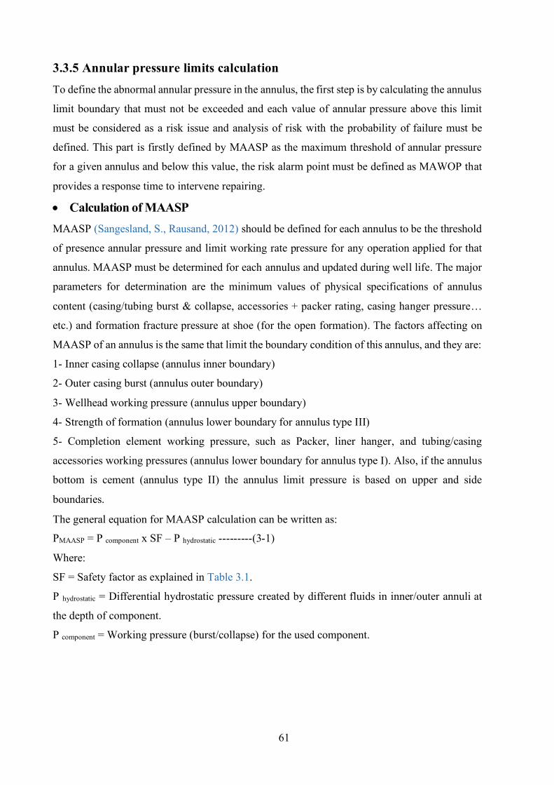
61
3.3.5 Annular pressure limits calculation To define the abnormal annular pressure in the annulus, the first step is by calculating the annulus
limit boundary that must not be exceeded and each value of annular pressure above this limit
must be considered as a risk issue and analysis of risk with the probability of failure must be
defined. This part is firstly defined by MAASP as the maximum threshold of annular pressure
for a given annulus and below this value, the risk alarm point must be defined as MAWOP that
provides a response time to intervene repairing.
• Calculation of MAASP MAASP (Sangesland, S., Rausand, 2012) should be defined for each annulus to be the threshold
of presence annular pressure and limit working rate pressure for any operation applied for that
annulus. MAASP must be determined for each annulus and updated during well life. The major
parameters for determination are the minimum values of physical specifications of annulus
content (casing/tubing burst & collapse, accessories + packer rating, casing hanger pressure…
etc.) and formation fracture pressure at shoe (for the open formation). The factors affecting on
MAASP of an annulus is the same that limit the boundary condition of this annulus, and they are:
1- Inner casing collapse (annulus inner boundary)
2- Outer casing burst (annulus outer boundary)
3- Wellhead working pressure (annulus upper boundary)
4- Strength of formation (annulus lower boundary for annulus type III)
5- Completion element working pressure, such as Packer, liner hanger, and tubing/casing
accessories working pressures (annulus lower boundary for annulus type I). Also, if the annulus
bottom is cement (annulus type II) the annulus limit pressure is based on upper and side
boundaries.
The general equation for MAASP calculation can be written as:
PMAASP = P component x SF – P hydrostatic ---------(3-1)
Where:
SF = Safety factor as explained in Table 3.1.
P hydrostatic = Differential hydrostatic pressure created by different fluids in inner/outer annuli at
the depth of component.
P component = Working pressure (burst/collapse) for the used component.
62
Table 3. 1 Safety factors for calculation of MAASP (A. RP, 2006)
Assumptions of calculation MAASP 1- Collapse calculation should be considered to be the lowest part of the cement top (if known)
or casing shoe.
2- The formation strength must be accounted at the casing shoe.
3- The calculation of casing burst and collapse pressure must be accounted for all casing profile
sections (weight/grade) and tubing collapse.
4- Original mud in surrounding annuli is degraded to base fluid (water or oil) due to aging and
sagging.
5- Tubing is evacuated for the collapse calculation of annulus ‘A’.
6- Annulus ‘A’ is evacuated for the annulus ‘B’ collapse calculation.
The MAASP calculator is an application to calculate the MAASP of each annulus. The MAASP
value for a specific annulus is the minimum value obtained from the calculations of each
component. In the calculation of the reservoir, MAASP must consider the pressure against the
perforations zone and its purpose is to determine the MASP permitted during the well
intervention to prevent formation fracturing. It cannot be used to determine a well integrity
MAASP limit for the operational phase.
When accounting for well aging, the MAASP (Amit Kumar et al., 2018) in this case criteria for
the annuli differ over the time and wall thickness changes, density, and composition of the
annulus fluid (if not assumed base fluid). So, the calculation must take into account the derated
physical properties and the value are different with the well age.
3.3.6 Application of risk analysis for annular thermal pressure For HPHT wells with trapped annulus contain a fluid able to expand and create thermal pressure,
the probability of casing failure depends on the amount of generated thermal pressure relative to
the permissible limit. So, the risk level will be treated based on an acceptable TAP limit under
thresholds and type of mitigation device applied.
63
3.3.6.1 Calculation of thermal annular pressure threshold It is the annular pressure that an annulus can withstand without affecting the burst or collapse
integrity of the related tubular strings. The thermal pressure threshold is set based on the value
of allowable APB that is determined based on annular pressure calculation as previously
discussed (temperature, annular fluid PVT and compressibility analysis, annulus tubular strength,
and production fluid properties). So, the allowable annular pressure limit calculated as follow
I- Allowable APB in annulus ‘A’ The allowable APB in Annulus ‘A’ can be obtained from API (A. RP, 2006), which states that
the MAWOP of annulus ‘A’ is 50% of the MIYP of the production casing (the outer casing of
the annulus ‘A’). Therefore,
∆Pallow, ‘A’ = 0.5 PMIYP - Pann, ‘A’ ML ----------------(3-2)
where:
PMIYP is the minimum internal yield pressure of the production casing,
Pann, A ML represents the annulus hydrostatic pressure at the midline.
II- Allowable APB in an outer annuli (‘B’, ‘C’…etc.) It is rated (Sathuvalli et al., 2016) as the minimum of the ∆Pallow-coll and ∆Pallow-bur.
where these two idioms represent respectively the APB at which the collapse of the inner string
or burst of outer string safety factor is equal to the collapse or burst design factor. In this
description two hypotheses are implicit:
1- The subject annulus is trapped and will have APB.
2- The next neighbour annulus not developed APB.
The inner string experiences a collapse load, and the outer string undergoes a burst load, keep
with these assumptions. The appropriate APB may now be connected to tubular design factors
First, think about the inner string which experiences a collapse load. The minimum collapse
safety factor SFcoll, min is obtained from
SFcoll,min =Pcoll
[∆𝑃+𝑃𝑎𝑛𝑛−(1−2𝑡
𝑑𝑜)𝑃𝑖𝑛𝑡,𝐿]𝑚𝑎𝑥
----------------(3-3)
where:
Pcoll is the temperature adjusted collapse strength of the string, do and t are the outside diameter
and wall thickness of casing, respectively.
The safe design must ensure that SFcoll, min > DFcoll ---------------(3-4)
Idioms means:
DFcoll is collapse differential pressure on the string
64
The denominator illustrates maximum collapse differential pressure on the string. The external
pressure on the string is the APB (∆p) acting on the hydrostatic pressure (pain) of the fluid in the
annulus. The internal pressure Pint, L is the minimum anticipated pressure profile in the
neighbouring annulus (to the left of the working annulus). The allowable APB for the collapse
of the inner string, ∆pallow-coll is determined by setting the minimum collapse safety factor in Eq.
(3-3) equal to the design factor, then
∆pallow-coll = {𝑃coll/𝐷𝐹 𝑐𝑜𝑙𝑙 + (1 −2𝑡
𝑑𝑜) 𝑃𝑖𝑛𝑡, 𝐿} 𝑚𝑎𝑥 − {𝑃𝑎𝑛𝑛}𝑚𝑎𝑥 -------(3-5)
In the equation above, the subscript “max” refers to that the quantities indicated are measured at
a depth where the differential pressure of collapse is maximum. We calculate APB for the burst
of the outer string, by a similar case, so
∆pallow-bur = 𝑃𝑏𝑢𝑟/𝐷𝐹 𝑏𝑢𝑟 + {𝑃ext, R}𝑚𝑎𝑥 − {𝑃𝑎𝑛𝑛}max ----------------(3-6)
Idioms means:
Pbur is the temperature adjusted internal pressure strength of the annulus outer string,
Pext, X is the minimum anticipated pressure profile in the neighboring annulus (annulus ’X’ to the
right of the working annulus).
The allowable APB for the annulus is obtained by
∆Pallow-ann = min {∆Pallow-coll , ∆Pallow-bur } -----------------(3-7)
The burst and collapse safety factors are equal to their general definition (the ratio between
differential pressure to the strength rating). In order to determine the allowable of APB, there are
some point that must be noted when used these safety factors definitions
1- The collapse of the inner string is the govern for the allowable annular pressure in most
situations the collapse rating of the inner string is either the API collapse rating or the
manufacturing rating in the case of own tubular.
2- The minimum acceptable safety factor for TAP is not always rigidly adhered to, but it should
be a break after careful consideration of a problem in the hand.
3- The TAP collapse design load usually 1.1, for this design is 10% above the factor of design
of drilling collapse loads, the purpose of this increase is to account for
A- Validity in stiffness of cement and formation, fluid PVT attitude, the initial temperature
distributed at the annulus.
B- Faulting in thermal analysis, assessment to be on the order of 10%.
C- Unknowns or unaccounted parameters such as the wearing effect of the casing is sometimes
set by prediction.
4- The estimation of maximum differential pressure in the string is done by a variety of
65
conditions. These conditions are included some parameters such as shallow barite plugs at the
shallow annulus points, mud settling, and another condition depends on the application.
3.3.6.2 Possible outcomes from thermal pressure risk analysis during design After identifying allowable APB there are two possible cases can be evaluated by risk analysis
1. TAP < allowable APB → Safe case When TAP less than allowable APB it will be the safety case for the selected design, so the
probability of failure, in this case, depends on
I- Reliability of selected casing physical properties (collapse, burst) with taking the effect of
well again based on expected production of field and well effect during life. The probability
increases with low reliability.
II- Amount of uncertainty of annular pressure calculation (module used for calculation and
accuracy of the parameter of heat and pressure, the scenario of well design). The probability
will increase when uncertainty increase.
III- Source of data such as expected for explorer wells or taken from previously drilled wells
and for selected annulus casing properties (API casing or non-API for high strength casing) the
probability of failure will increase when we are far from API or using some predictions.
IV- Safety factor applied for design (burst, collapse, tension), high safety factor will decrease
the probability of failure, but the safety factor must be selected in the range of API
recommendation.
V- Amount of pressure difference between TAP and allowable limit, the high difference
decreases the probability of failure.
VI- Presence of another source of annular pressure such as AP or/and SCP. That will increase
the probability of failure, in this case, the risk analysis of each annular pressure type must be
applied separately, and the final risk will be summed and checked.
2. TAP > allowable APB → Risk case In this case, the designer must use one or more of the mitigation methods (as listed in chapter
two) starting with casing strength and wall thickness improvement. In this case, the probability
of well integrity failure by casing failure due to abnormal annular pressure is built on the
reliability of the mitigation device that is applied. The new risk calculation is based on the amount
of annular pressure after modification by mitigation device, this value will be re-entered with an
acceptable probability of failure in the new risk equation then the final risk is the base of
accepting this modification by taking into account the principle of selecting the optimum
mitigation device.
66
3.3.6.3 Reliability analysis The quantitative risk assessment are built on reliability analysis of mitigation device that protects
well integrity against abnormal annular pressure for APB, so the reliability analysis must perform
as follow (Sangesland, S., Rausand, 2012)
1- Define and become familiar with the system This step consists of the define the operational situation, review of the well diagram, construction
of annuli properties and fluid composition (annulus boundary and PVT analysis), and listing of
possible mitigation devices with their functions.
2- Define failure modes and causes of failure Applied for selected mitigation devices. By analysing possible failure modes of applied device and
effect on mitigation system and well integrity. The best method for failure investigation is FMECA.
The target of the FMECA is to define all the expected failure modes, cause of this failure, and
effects for each of the elements of the system, also application of HAZOP can provide the worst
failure scenario for mitigation device failure with effect on the system( well integrity) failure and
plant impaction.
4- Build a reliability model of the mitigation system There are many alternative models available, and the selection of models depends on what type of
system states and available data to support the models. For more easy work recommended using
FTA, since this method is axiomatic and easy to understand (at least for the qualitative parts).
3.3.6.3.1 Determination of Reliability for TAP mitigation techniques Generally, the reliability of an engineering part can be obtained in two ways:
1- Estimate reliability from frequency data.
2- Estimation of reliability by full-scale counting of the sample space and counting favorable
results.
The first approach needs data about quality and product failure. The latter approach includes a
detailed physical model (or process) of the system and the engineering parameters governing its
output. The reported data of abnormal annular pressure accidents does not permit a direct evaluation
of the reliability of a given annular pressure mitigation device due to the following reasons:
1- The outer annuli of an SSW cannot be directly monitored.
2- Published reports of downhole pressure-temperature measurements in annuli do not contain the
application of TAP mitigation techniques (other than the open hole).
3- The investigation of case studies of TAP records failures (the Marlin (Bradford, D. W., 2002),
Mad Dog (P. D. Pattillo et al., 2007) and the Pompano wells (Phillip D. Pattillo, Cocales, et al.,
67
2004)) investigate the cause(s) of failure of the casing(s) and define APB in an annulus without a
mitigation technique as a probable cause.
4- This is only one published case study contains fibber optic cables (device to measure the
temperature) of the fluids in the annulus “A “ in Marlin re-designed well, so it can determine the
performance of the VIT and the IPF.
It is evident from the previous discussion that the efficiency of the TAP mitigation system must
be assessed during the design process, and its effect on the well's life should be calculated using
other approaches.
Reliability evaluation for mitigation device is performed in four phases:
1- Define the multiple failure modes (as applied in the wellbore system).
2- Evaluate the reliability of the mitigating system by the individual (element).
3- Assess the mitigating instrument's effect on the structural strength of other elements.
4- Determine the effect on life expectancy and the need for intervention.
Quantifying these aspects of a mitigation strategy can be difficult or even impossible since
numerical results from simulation cannot represent the real reliability of the system. So, Phase.1
may be the only measurable step for this evaluation.
3.3.6.4 Result reporting It is essential that all outcomes of risk analysis are reported, along with the assumptions and
limitations made. Strategies requiring further follow-up, whether looking right to the need for
redesign or revising planning, operating or maintenance procedures, need to be adequately
emphasized. Responsible persons or departments must always be appointed to recommendations.
3.3.7 Application of risk analysis for SCP The development of risk analysis based on managing of SCP and probability of presence during
well life to decide for casing selection and future remediations. So, the probability of failure and
risk calculation depends on:
I- Accurate calculation of SCP by applying the appropriate model as discussed in chapter one for
new wells design and based on pressure measurement on wellhead for current wells.
II- Type of the fluid in the annulus (by checking removed fluid), and the remaining hydrostatic
of annuls original fluid (almost water base).
III- Source of data, expected, or recorded. In some cases, there is a rough assumption by using
the source formation pressure directly.
IV- Risk assessment after final well status when including final cement quality and annulus
testing.
68
V- Well type, function (production, injection…etc.) and expected well life and well plan (to
consider well aging).
VI- Combination annular pressure SCP, TAP and AP.
VII- The acceptable risk threshold (allowable annular pressure) will be updated with well aging
and future scenarios of well plan and functionality (production, injection, shut-in, etc..).
3.3.7.1 Diagnostic test of SCP It can be defined as tests or methods conducted to assess the severity of the presence of casing
pressure and to help to identify the source of this pressure in certain situations and possible
remediation methods. These tests consist of the analysis of sampling fluids, logging of well, fluid
levels monitoring, pressure tests, maintenance of wellhead, Build-up, and Bleed down test of
pressure (B-B test).
- Fluid sampling Applied to identify the influx source by analysing fluid sample properties (density and
composition).
- Logging analysis of well Applied to detect the location of the fluid and source formation by using CBL, temperature and
noise analysis, also oxygen activation log to detect water feeding channels and TDT logs to detect
the accumulation of gas in the annular.
- Fluid level monitoring Applied to detect and verify the tubing leaks by performing a conventional acoustic test. But this
test most of the time is not as easy because of gas cut fluids, the 90 degrees well head turns, and
annular geometry.
- Pressure tests After SCP bleed down the pressure test applied to determine the annular fluid density and
indication of surface pressure by assuming the lifted annulus fluid can be replaced by gas.
- Maintenance of wellhead This operation can help to detect and eliminate the connection between annulus strings if it is
found at the wellhead. So, the greasing of the wellhead can help to eliminate this problem.
- Build-up and bleed down of pressure (B-B test) This test is usually applied through a ½.in venting valve. It can provide information about the
volume of annular, content of gas and flow capacity of channel or micro-annulus, source of fluids,
and flow rate. The flow rate of the bleed-off test can be accounted for and correlate to the time
curve to determine the total bleed volume. The pressure of the casing is also recorded, and a
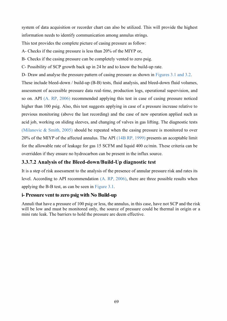
69
system of data acquisition or recorder chart can also be utilized. This will provide the highest
information needs to identify communication among annulus strings.
This test provides the complete picture of casing pressure as follow:
A- Checks if the casing pressure is less than 20% of the MIYP or,
B- Checks if the casing pressure can be completely vented to zero psig.
C- Possibility of SCP growth back up in 24 hr and to know the build-up rate.
D- Draw and analyse the pressure pattern of casing pressure as shown in Figures 3.1 and 3.2.
These include bleed-down / build-up (B-B) tests, fluid analysis, and bleed-down fluid volumes,
assessment of accessible pressure data real-time, production logs, operational supervision, and
so on. API (A. RP, 2006) recommended applying this test in case of casing pressure noticed
higher than 100 psig. Also, this test suggests applying in case of a pressure increase relative to
previous monitoring (above the last recording) and the case of new operation applied such as
acid job, working on sliding sleeves, and changing of valves in gas lifting. The diagnostic tests
(Milanovic & Smith, 2005) should be repeated when the casing pressure is monitored to over
20% of the MIYP of the affected annulus. The API (14B RP, 1999) presents an acceptable limit
for the allowable rate of leakage for gas 15 SCFM and liquid 400 cc/min. These criteria can be
overridden if they ensure no hydrocarbon can be present in the influx source.
3.3.7.2 Analysis of the Bleed-down/Build-Up diagnostic test It is a step of risk assessment to the analysis of the presence of annular pressure risk and rates its
level. According to API recommendation (A. RP, 2006), there are three possible results when
applying the B-B test, as can be seen in Figure 3.1.
i- Pressure vent to zero psig with No Build-up Annuli that have a pressure of 100 psig or less, the annulus, in this case, have not SCP and the risk will be low and must be monitored only, the source of pressure could be thermal in origin or a mini rate leak. The barriers to hold the pressure are deem effective.
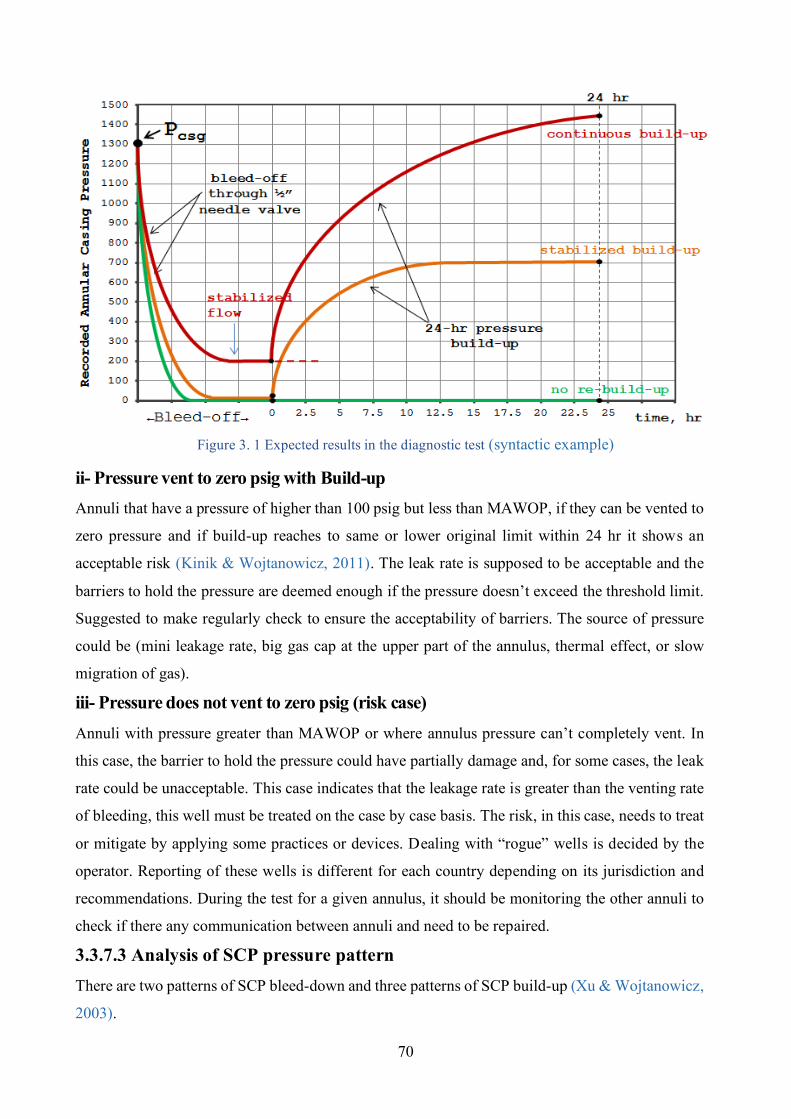
70
Figure 3. 1 Expected results in the diagnostic test (syntactic example)
ii- Pressure vent to zero psig with Build-up Annuli that have a pressure of higher than 100 psig but less than MAWOP, if they can be vented to
zero pressure and if build-up reaches to same or lower original limit within 24 hr it shows an
acceptable risk (Kinik & Wojtanowicz, 2011). The leak rate is supposed to be acceptable and the
barriers to hold the pressure are deemed enough if the pressure doesn’t exceed the threshold limit.
Suggested to make regularly check to ensure the acceptability of barriers. The source of pressure
could be (mini leakage rate, big gas cap at the upper part of the annulus, thermal effect, or slow
migration of gas).
iii- Pressure does not vent to zero psig (risk case) Annuli with pressure greater than MAWOP or where annulus pressure can’t completely vent. In
this case, the barrier to hold the pressure could have partially damage and, for some cases, the leak
rate could be unacceptable. This case indicates that the leakage rate is greater than the venting rate
of bleeding, this well must be treated on the case by case basis. The risk, in this case, needs to treat
or mitigate by applying some practices or devices. Dealing with “rogue” wells is decided by the
operator. Reporting of these wells is different for each country depending on its jurisdiction and
recommendations. During the test for a given annulus, it should be monitoring the other annuli to
check if there any communication between annuli and need to be repaired.
3.3.7.3 Analysis of SCP pressure pattern There are two patterns of SCP bleed-down and three patterns of SCP build-up (Xu & Wojtanowicz,
2003).
71
1- Instant SCP bleed-down pattern As shown in Figure 3.2-A, this type is popular in vent and lubricate remediation techniques. The
casing pressure will quickly be vented with the release of annulus fluid and followed by the injection
of killing mud, amount, and properties of released fluid that will be measured and recorded.
2- Long bleed-down pattern This type as indicated in Figure 3.2-B is a special case of instant bleed-down with the limited
opening of the needle valve and without fluid removal from the annulus or in sometimes, the
operators control the venting valve to decrease the removed fluid. The casing pressure will stabilize
at a value not reached zero.
3- Normal build-up pattern This type as shown in Figure 3.2-C represents the normal performance of annulus pressure build-
up for a well under SCP problem. After the bleed-down, the pressure of the casing will rise instantly
(early time performance) then stabilize at a specific value (late time performance), the transition
part of pressure performance represents a gradual increase. The stabilized pressure of the casing
was obtained by the weight of mud and the pressure source of the formation fluid. Transient time
is managed by the severity of fluid migration in the cement channel and through the mud column.
4- S-shape build-up pattern This type is a special case of the normal build-up pattern as shown in Figure 3.2-D, different by no
gas found in the column of liquid in the pressure build-up at an early stage, at this stage no
significant casing pressure increase. The pressure increases gradually and stabilizes finally at a
specific level.
5- Incomplete build-up pattern After bleed-down, if the pressure of formation is higher enough the build-up response shows an
incomplete pattern. The casing pressure rises continuously as shown in Figure 3.2-E with slow and
steady increases due to the constant flow of gas from cement channels, and no late time found
during the build-up period (one day), also the pressure needs long enough time (more than one day)
to stabilize. Almost the final pressure will be high and risky.
Interpretation of these patterns can provide information about the level of risk and discuss the
possibility of decrease this risk by select an optimum remediation plan.
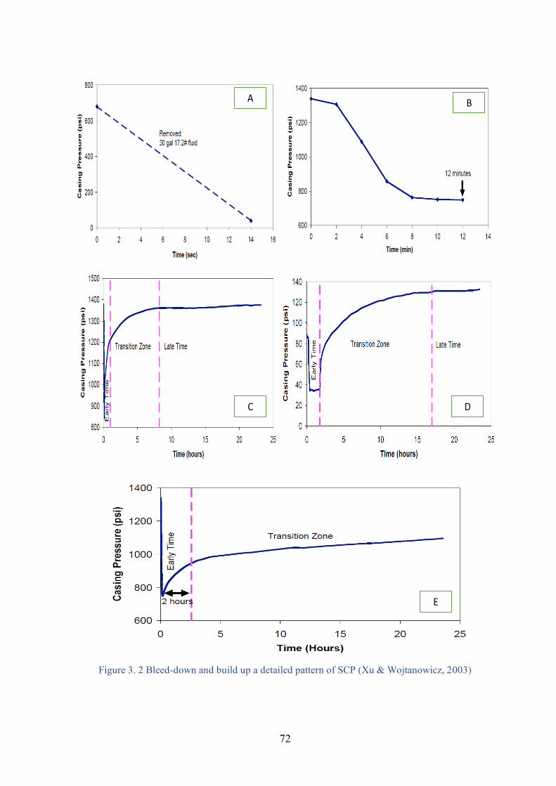
72
Figure 3. 2 Bleed-down and build up a detailed pattern of SCP (Xu & Wojtanowicz, 2003)
(
A B
C D
E
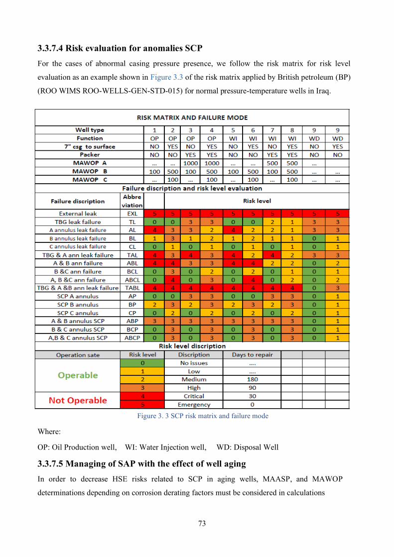
73
3.3.7.4 Risk evaluation for anomalies SCP For the cases of abnormal casing pressure presence, we follow the risk matrix for risk level
evaluation as an example shown in Figure 3.3 of the risk matrix applied by British petroleum (BP)
(ROO WIMS ROO-WELLS-GEN-STD-015) for normal pressure-temperature wells in Iraq.
Figure 3. 3 SCP risk matrix and failure mode
Where:
OP: Oil Production well, WI: Water Injection well, WD: Disposal Well
3.3.7.5 Managing of SAP with the effect of well aging In order to decrease HSE risks related to SCP in aging wells, MAASP, and MAWOP
determinations depending on corrosion derating factors must be considered in calculations
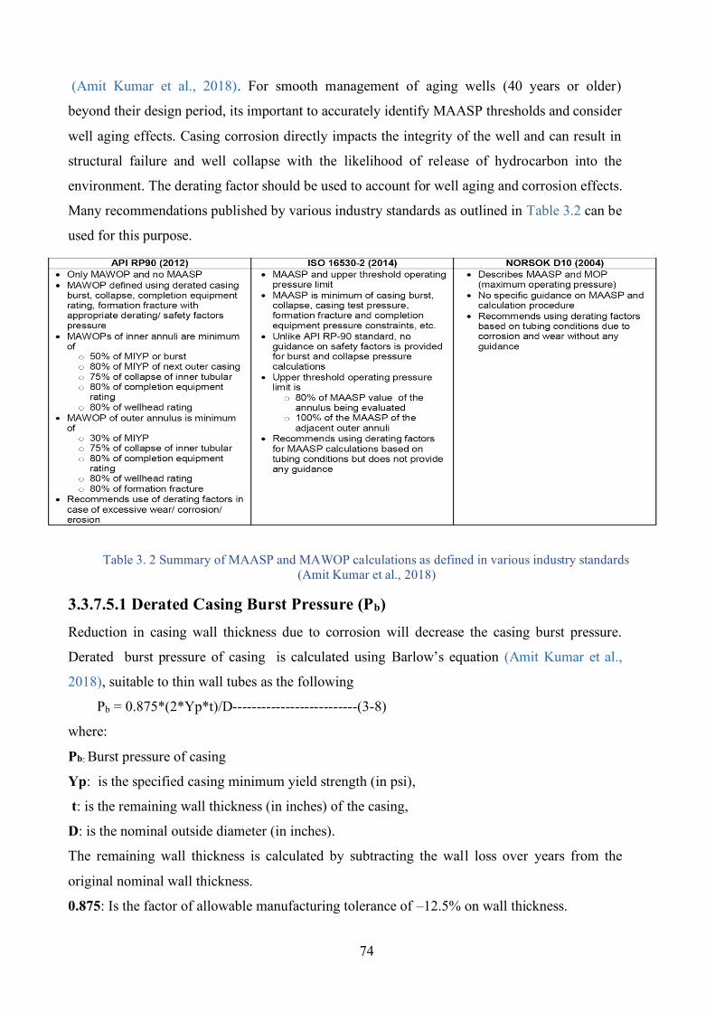
74
(Amit Kumar et al., 2018). For smooth management of aging wells (40 years or older)
beyond their design period, its important to accurately identify MAASP thresholds and consider
well aging effects. Casing corrosion directly impacts the integrity of the well and can result in
structural failure and well collapse with the likelihood of release of hydrocarbon into the
environment. The derating factor should be used to account for well aging and corrosion effects.
Many recommendations published by various industry standards as outlined in Table 3.2 can be
used for this purpose.
Table 3. 2 Summary of MAASP and MAWOP calculations as defined in various industry standards (Amit Kumar et al., 2018)
3.3.7.5.1 Derated Casing Burst Pressure (Pb) Reduction in casing wall thickness due to corrosion will decrease the casing burst pressure.
Derated burst pressure of casing is calculated using Barlow’s equation (Amit Kumar et al.,
2018), suitable to thin wall tubes as the following
Pb = 0.875*(2*Yp*t)/D--------------------------(3-8)
where:
Pb: Burst pressure of casing
Yp: is the specified casing minimum yield strength (in psi),
t: is the remaining wall thickness (in inches) of the casing,
D: is the nominal outside diameter (in inches).
The remaining wall thickness is calculated by subtracting the wall loss over years from the
original nominal wall thickness.
0.875: Is the factor of allowable manufacturing tolerance of –12.5% on wall thickness.
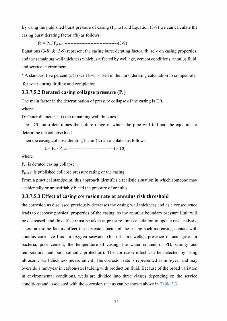
75
By using the published burst pressure of casing (Ppub-b) and Equation (3-8) we can calculate the
casing burst derating factor (fb) as follows:
fb = Pb / Ppub-b -----------------------------------(3-9)
Equations (3-8) & (3-9) represent the casing burst derating factor, fb, rely on casing properties,
and the remaining wall thickness which is affected by well age, cement conditions, annulus fluid,
and service environment.
* A standard five percent (5%) wall loss is used in the burst derating calculation to compensate
for wear during drilling and completion.
3.3.7.5.2 Derated casing collapse pressure (Pc) The main factor in the determination of pressure collapse of the casing is D/t,
where
D: Outer diameter, t: is the remaining wall thickness.
The ‘D/t’ ratio determines the failure range in which the pipe will fail and the equation to
determine the collapse load.
Then the casing collapse derating factor (fc) is calculated as follows:
fc = Pc / Ppub-c -----------------------------(3-10)
where
Pc: is derated casing collapse,
Ppub-c: is published collapse pressure rating of the casing
From a practical standpoint, this approach identifies a realistic situation in which someone may
accidentally or unjustifiably bleed the pressure of annulus.
3.3.7.5.3 Effect of casing corrosion rate at annulus risk threshold the corrosion as discussed previously decreases the casing wall thickness and as a consequence
leads to decrease physical properties of the casing, so the annulus boundary pressure limit will
be decreased, and this effect must be taken at pressure limit calculation to update risk analysis.
There are some factors affect the corrosion factor of the casing such as (casing contact with
annulus corrosive fluid or oxygen seawater (for offshore wells), presence of acid gases or
bacteria, poor cement, the temperature of casing, the water content of PH, salinity and
temperature, and poor cathodic protection). The corrosion effect can be detected by using
ultrasonic wall thickness measurement. The corrosion rate is represented as mm/year and may
override 1 mm/year in carbon-steel tubing with production fluid. Because of the broad variation
in environmental conditions, wells are divided into three classes depending on the service
conditions and associated with the corrosion rate as can be shown above in Table 3.3
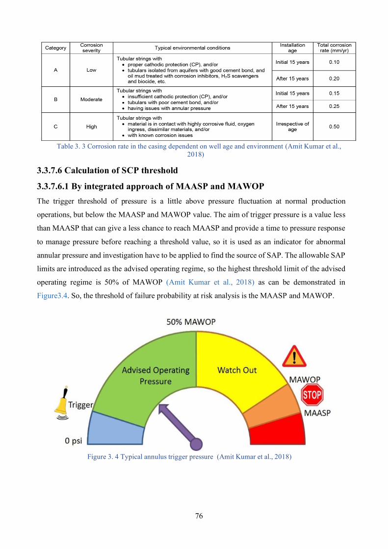
76
Table 3. 3 Corrosion rate in the casing dependent on well age and environment (Amit Kumar et al., 2018)
3.3.7.6 Calculation of SCP threshold
3.3.7.6.1 By integrated approach of MAASP and MAWOP The trigger threshold of pressure is a little above pressure fluctuation at normal production
operations, but below the MAASP and MAWOP value. The aim of trigger pressure is a value less
than MAASP that can give a less chance to reach MAASP and provide a time to pressure response
to manage pressure before reaching a threshold value, so it is used as an indicator for abnormal
annular pressure and investigation have to be applied to find the source of SAP. The allowable SAP
limits are introduced as the advised operating regime, so the highest threshold limit of the advised
operating regime is 50% of MAWOP (Amit Kumar et al., 2018) as can be demonstrated in
Figure3.4. So, the threshold of failure probability at risk analysis is the MAASP and MAWOP.
Figure 3. 4 Typical annulus trigger pressure (Amit Kumar et al., 2018)
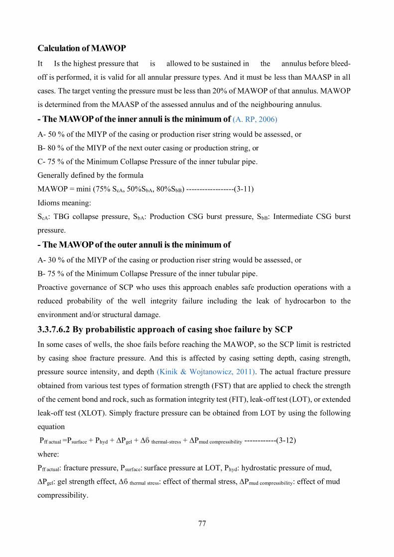
77
Calculation of MAWOP It Is the highest pressure that is allowed to be sustained in the annulus before bleed-
off is performed, it is valid for all annular pressure types. And it must be less than MAASP in all
cases. The target venting the pressure must be less than 20% of MAWOP of that annulus. MAWOP
is determined from the MAASP of the assessed annulus and of the neighbouring annulus.
- The MAWOP of the inner annuli is the minimum of (A. RP, 2006)
A- 50 % of the MIYP of the casing or production riser string would be assessed, or
B- 80 % of the MIYP of the next outer casing or production string, or
C- 75 % of the Minimum Collapse Pressure of the inner tubular pipe.
Generally defined by the formula
MAWOP = mini (75% ScA, 50%SbA, 80%SbB) ------------------(3-11)
Idioms meaning:
ScA: TBG collapse pressure, SbA: Production CSG burst pressure, SbB: Intermediate CSG burst
pressure.
- The MAWOP of the outer annuli is the minimum of A- 30 % of the MIYP of the casing or production riser string would be assessed, or
B- 75 % of the Minimum Collapse Pressure of the inner tubular pipe.
Proactive governance of SCP who uses this approach enables safe production operations with a
reduced probability of the well integrity failure including the leak of hydrocarbon to the
environment and/or structural damage.
3.3.7.6.2 By probabilistic approach of casing shoe failure by SCP In some cases of wells, the shoe fails before reaching the MAWOP, so the SCP limit is restricted
by casing shoe fracture pressure. And this is affected by casing setting depth, casing strength,
pressure source intensity, and depth (Kinik & Wojtanowicz, 2011). The actual fracture pressure
obtained from various test types of formation strength (FST) that are applied to check the strength
of the cement bond and rock, such as formation integrity test (FIT), leak-off test (LOT), or extended
leak-off test (XLOT). Simply fracture pressure can be obtained from LOT by using the following
equation
Pff actual =Psurface + Phyd + ∆Pgel + ∆ϐ thermal-stress + ∆Pmud compressibility ------------(3-12)
where:
Pff actual: fracture pressure, Psurface: surface pressure at LOT, Phyd: hydrostatic pressure of mud,
∆Pgel: gel strength effect, ∆ϐ thermal stress: effect of thermal stress, ∆Pmud compressibility: effect of mud
compressibility.
78
The risk analysis gives a probability of shoe failure that must be considered in the SCP permissible
range. So, from these two approaches, we select the lowest value between LOT (probabilistic
approach) and MAWOP (integrated approach) to be the limit for SCP allowable in each annulus.
3.3.8 Annular pressure monitoring The best practice for abnormal annular pressure risk indication and applied mitigation effectiveness
(A. RP, 2006) done by periodically monitoring of casing pressure by indicating Pcsg presence and its
value. There are differences between onshore and offshore wells monitoring:
I- Onshore wells
the surveillance of casing pressure is easier by installing a gauge on the annulus from the wellhead
and make a monthly checking or as required to ensure the annulus follows the acceptable and safety
criteria.
II- Offshore wells Surveillance of casing pressure is various between SSW and fixed platform, in the SSW the annulus
pressure of tubing-casing (annulus ‘A’) is the only that can be observed, for other annuli are separated
after landing of the casing, so it is a technical challenge for monitoring annular pressure in these
annuli. For fixed platform wells, the annulus pressure can be observed monthly from each non-
structural casing strings that are equipped with a gauge and the annular pressure will be checked from
the wellhead by the fitted taps or flanges for each annulus. Increasing monitoring frequency will
improve the capability to detect casing pressure. This operation performs for producing, injection,
shut-in, and temporarily abandoned wells to early indication, performance evaluation, and control of
annular pressure risk. The monitoring can be done by different strategies like but not limited to
Supervisory Control and Data Acquisition system (SCADA), a recorder chart pressure pen, scaled
pressure gauges. All monitoring must be reported. The monitoring is classified in to:
1- Normal observation to well that has No casing pressure Any annulus able to contain pressure must be continuously or regularly monitored for determination
if the pressure of casing is present in the annulus. The minimum, routine monitoring must be
applied at least once each six months.
2- Observation of wells that have SCP Minimum routine observation of annuli with SCP should be applied once every month. And
minimum, for the other annuli of the well that do not record casing pressure, must be observed at
the same frequency. The monitoring frequency influenced by the operativity of the platform,
recorded annulus pressure relative to annulus pressure threshold, the behaviour of pressure
79
increasing, source of annular pressure of other annuli of the well (AP, TAP), risk level recorded by
monitoring.
3- Observation of wells that have a thermal casing pressure or TAP The important section of monitoring for this type is at well start-up, the operator must set the
frequency of wells observation where one or more annuli showed a thermal casing pressure. The
monitoring result should be recorded. The minimum, routine observation of annuli that have
thermal casing pressure should be applied once every month. Production wells with thermal casing
pressure should be observed during choke size increase. The minimum, observation for other annuli
of the well that do not exhibit casing pressure should be observed at the same frequency. The
monitoring frequency was influenced by operativity of the platform, recorded annulus pressure
relative to annulus pressure threshold, the stable characteristic production of the well, the stability
of annular pressure, presence of annular pressure for the other annuli.
4- Observation of wells with applied annular pressures (AP) Applied pressure by the operator should be observed and recorded as per requiring this applied
pressure. The minimum, routine observation of the annuli with AP should be applied once every
month, and for the other annuli in the well should be observed in accordance with the timeframe
set by the operator and based on the purpose of AP and limits, also for any case of applied pressure
change, the annulus monitoring mandatory performed.
3.3.9 Final risk assessment Here the designer has all the data and possible scenarios to build the complete risk tree (analysis).
The risk level must be defined based on standard risk calculation and show the severity of this risk
with possible treatments and evaluation of risk after toleration. As made by a set of assumptions for
possible failure scenarios of well integrity failure by abnormal annular pressure (NORSOK, 2004),
the operator company policies, government rules, and analysis of previous accidents and scenarios
will guide the designer at this task.
80
CHAPTER FOUR LIMITATIONS AND OPTIMIZATION OF SELECTING ANNULAR PRESSURE MITIGATION TECHNIQUES
The abnormal annular pressure mitigation techniques are different in terms of cost, operating
difficulty, reliability, applied condition, failure rate, and working mechanism. Reported data
and field experiences show that there is not a universal solution for abnormal annular pressure
mitigation (Payne et al., 2007). The selection of an optimum mitigation technique is based on
some parameters, starting by analysing the case step by step. This section specialized in TAP
mitigation devices.
4.1 Definition of the design environment 1- Type of the well based on onshore (platform and SSW) and offshore wells.
2- Type of well based on a range of bottom hole pressure and temperature.
4.1.1 Type of the well based on onshore wells, offshore wells
A- Onshore wells This type of well is easier for control TAP due to the ability to access all the annuli and vent
the pressure when needs, also monitor the casing pressure during production. This type of wells
does not need to apply a mitigation device for APB.
B- Offshore wells for SSW This type of well is more difficult to control TAP due to limited access to all annuli, the annulus
‘A’ is the only one that can be reached and vented. So, a mitigation device needs to be applied
in this case when dangerous TAP is present. Remediation for this well due to damage by annular
pressure is highly costed, limited, low possibility of success, and difficult operationally, also in
some cases the well abandon. The selection of an optimum mitigation method is a big challenge
based on well condition, range of TAP, well functionality, formation pressures properties, and
annulus fluid properties. All scenarios of drilling, production, and injection must be considered
during design.
4.1.2 Type of well Based on the range of bottom hole pressure and
temperature For HPHT wells, the optimization of design depends on the range of pressure and temperature.
There are three ranges (Payne et al., 2007).
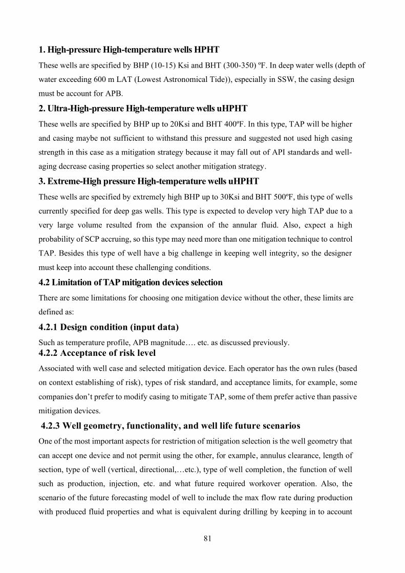
81
1. High-pressure High-temperature wells HPHT These wells are specified by BHP (10-15) Ksi and BHT (300-350) ºF. In deep water wells (depth of
water exceeding 600 m LAT (Lowest Astronomical Tide)), especially in SSW, the casing design
must be account for APB.
2. Ultra-High-pressure High-temperature wells uHPHT These wells are specified by BHP up to 20Ksi and BHT 400ºF. In this type, TAP will be higher
and casing maybe not sufficient to withstand this pressure and suggested not used high casing
strength in this case as a mitigation strategy because it may fall out of API standards and well-
aging decrease casing properties so select another mitigation strategy.
3. Extreme-High pressure High-temperature wells uHPHT These wells are specified by extremely high BHP up to 30Ksi and BHT 500ºF, this type of wells
currently specified for deep gas wells. This type is expected to develop very high TAP due to a
very large volume resulted from the expansion of the annular fluid. Also, expect a high
probability of SCP accruing, so this type may need more than one mitigation technique to control
TAP. Besides this type of well have a big challenge in keeping well integrity, so the designer
must keep into account these challenging conditions.
4.2 Limitation of TAP mitigation devices selection There are some limitations for choosing one mitigation device without the other, these limits are
defined as:
4.2.1 Design condition (input data) Such as temperature profile, APB magnitude…. etc. as discussed previously. 4.2.2 Acceptance of risk level Associated with well case and selected mitigation device. Each operator has the own rules (based
on context establishing of risk), types of risk standard, and acceptance limits, for example, some
companies don’t prefer to modify casing to mitigate TAP, some of them prefer active than passive
mitigation devices.
4.2.3 Well geometry, functionality, and well life future scenarios One of the most important aspects for restriction of mitigation selection is the well geometry that
can accept one device and not permit using the other, for example, annulus clearance, length of
section, type of well (vertical, directional,…etc.), type of well completion, the function of well
such as production, injection, etc. and what future required workover operation. Also, the
scenario of the future forecasting model of well to include the max flow rate during production
with produced fluid properties and what is equivalent during drilling by keeping in to account
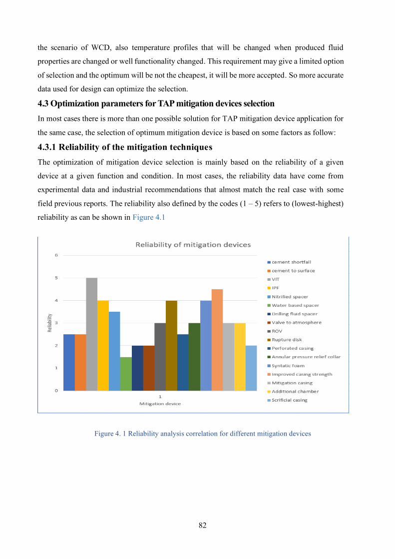
82
the scenario of WCD, also temperature profiles that will be changed when produced fluid
properties are changed or well functionality changed. This requirement may give a limited option
of selection and the optimum will be not the cheapest, it will be more accepted. So more accurate
data used for design can optimize the selection.
4.3 Optimization parameters for TAP mitigation devices selection In most cases there is more than one possible solution for TAP mitigation device application for
the same case, the selection of optimum mitigation device is based on some factors as follow:
4.3.1 Reliability of the mitigation techniques The optimization of mitigation device selection is mainly based on the reliability of a given
device at a given function and condition. In most cases, the reliability data have come from
experimental data and industrial recommendations that almost match the real case with some
field previous reports. The reliability also defined by the codes (1 – 5) refers to (lowest-highest)
reliability as can be shown in Figure 4.1
Figure 4. 1 Reliability analysis correlation for different mitigation devices
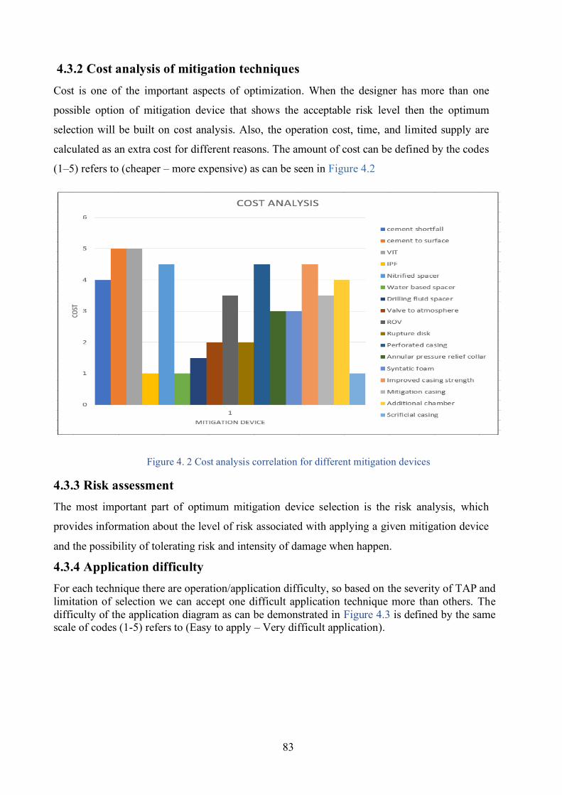
83
4.3.2 Cost analysis of mitigation techniques Cost is one of the important aspects of optimization. When the designer has more than one
possible option of mitigation device that shows the acceptable risk level then the optimum
selection will be built on cost analysis. Also, the operation cost, time, and limited supply are
calculated as an extra cost for different reasons. The amount of cost can be defined by the codes
(1–5) refers to (cheaper – more expensive) as can be seen in Figure 4.2
Figure 4. 2 Cost analysis correlation for different mitigation devices
4.3.3 Risk assessment The most important part of optimum mitigation device selection is the risk analysis, which
provides information about the level of risk associated with applying a given mitigation device
and the possibility of tolerating risk and intensity of damage when happen.
4.3.4 Application difficulty For each technique there are operation/application difficulty, so based on the severity of TAP and limitation of selection we can accept one difficult application technique more than others. The difficulty of the application diagram as can be demonstrated in Figure 4.3 is defined by the same scale of codes (1-5) refers to (Easy to apply – Very difficult application).
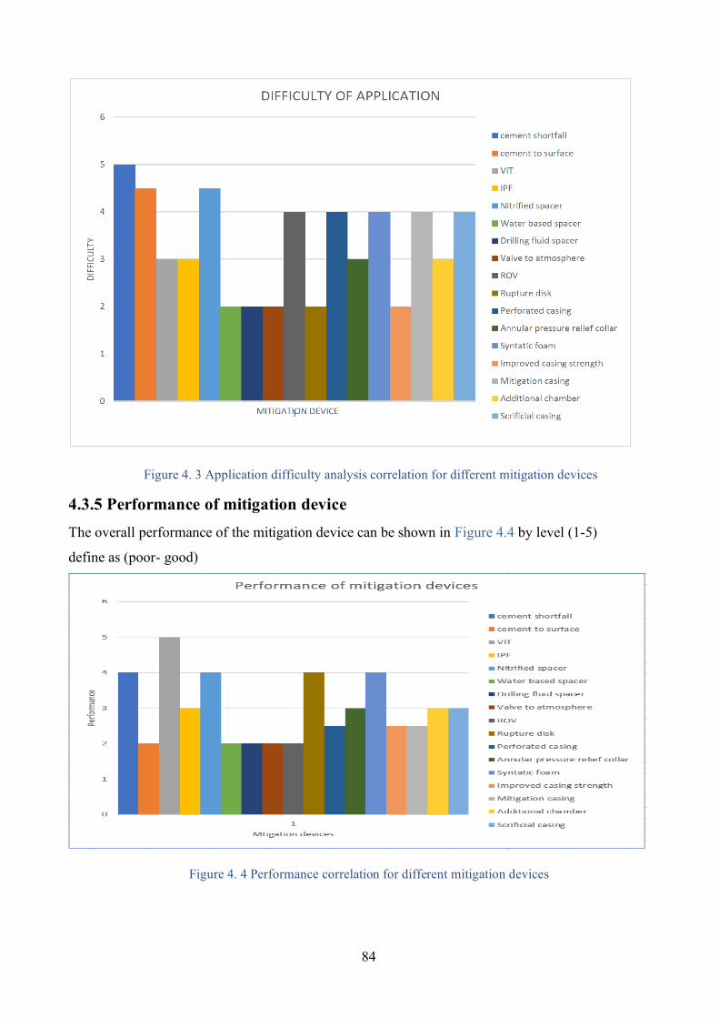
84
Figure 4. 3 Application difficulty analysis correlation for different mitigation devices
4.3.5 Performance of mitigation device The overall performance of the mitigation device can be shown in Figure 4.4 by level (1-5)
define as (poor- good)
Figure 4. 4 Performance correlation for different mitigation devices
85
4.4 Optimization summary The optimum device will select based on previous analysis, for the function of the TAP mitigation
device must have the lowest cost, highest reliability, easer feasibility, and must provide good
performance with safe condition. So, the recommended option applied as follow:
1- High-cost methods applied in the case of high-temperature wells and no other choice can be
applied instead.
2- High reliability required for all methods, but for some of them such as rupture disk the
reliability can be increase by the increasing number of disks used, for others that have not high
reliability the decision making based on RL and possible modification.
3- Low (easy) operation requirements are required for all applications, but for a special condition
such as required of a nitrified spacer or syntactic foam the application is overcome relative to
well condition.
4- High performance is required for each method, but relative to well condition and optimization
parameter, the designer can modify the selection.
4.5 Priority of mitigation devices selection By application of these points we can set the final strategy of optimum selection as
I- Increasing casing strength.
A- Improving casing steel grade.
B- Improving casing wall thickness.
II- Eliminate the annular trapped volume.
A- Wholly annulus cementation.
III- Venting the TAP.
A- Open shoe.
B- Using rupture disk.
IV- Balancing the volume of heat expansion
A- Annular pressure relief collar.
B- Compressible foam.
C- Additional chamber.
D- Spacer shrinkage fluid.
E- Hollow microsphere.
V- Isolate the source of heat.
A- IPF.
B- VIT.
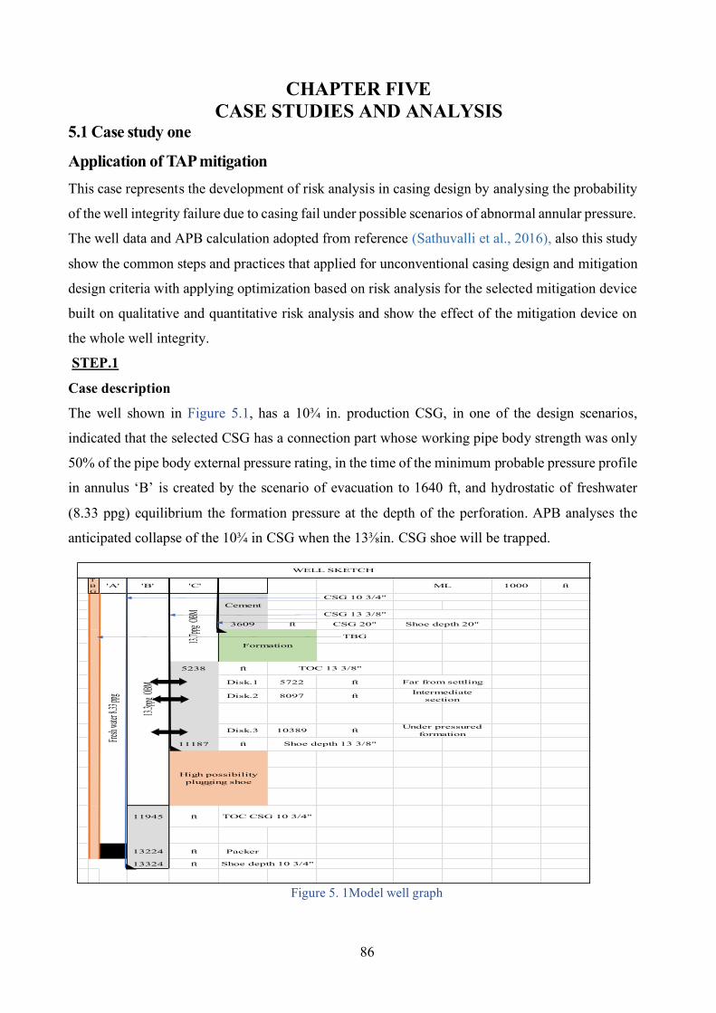
86
CHAPTER FIVE CASE STUDIES AND ANALYSIS
5.1 Case study one
Application of TAP mitigation This case represents the development of risk analysis in casing design by analysing the probability
of the well integrity failure due to casing fail under possible scenarios of abnormal annular pressure.
The well data and APB calculation adopted from reference (Sathuvalli et al., 2016), also this study
show the common steps and practices that applied for unconventional casing design and mitigation
design criteria with applying optimization based on risk analysis for the selected mitigation device
built on qualitative and quantitative risk analysis and show the effect of the mitigation device on
the whole well integrity.
STEP.1 Case description
The well shown in Figure 5.1, has a 10¾ in. production CSG, in one of the design scenarios,
indicated that the selected CSG has a connection part whose working pipe body strength was only
50% of the pipe body external pressure rating, in the time of the minimum probable pressure profile
in annulus ‘B’ is created by the scenario of evacuation to 1640 ft, and hydrostatic of freshwater
(8.33 ppg) equilibrium the formation pressure at the depth of the perforation. APB analyses the
anticipated collapse of the 10¾ in CSG when the 13⅜in. CSG shoe will be trapped.
Figure 5. 1Model well graph
TBG
'A' 'B' 'C' 1000 ft
CSG 10 3/4"Cement
CSG 13 3/8"
3609 ft CSG 20"
TBG
5238 ft
Disk.1 5722 ft
Disk.2 8097 ft
Disk.3 10389 ft
11187 ft
11945 ft
13224 ft Packer
13324 ft
WELL SKETCH
Under pressured formation
Intermediate section
Far from settling
13.3ppg
OBM
High possibility plugging shoe
13.7ppg
OBM
Formation
Shoe depth 20"
ML
Fresh w
ater 8.3
3 ppg
Shoe depth 10 3/4"
TOC CSG 10 3/4"
TOC 13 3/8"
Shoe depth 13 3/8"
87
STEP.2
In this step we define a well barriers against the expected abnormal annular pressure, these barriers
are divided into three types
1- Wellhead seals
These barrier work against abnormal annular pressure, but it represented the last barrier for well
integrity and design of this barrier based on rating pressure (wellhead) and annulus content (PVT
of trapped or expected invaded fluid). So, the importance to provide another barrier to be the
primary protection line in the annulus when the secondary integrity failure or APB exceed s
permissible limits.
2- Casing annulus strength
Enhancing this barrier is not the most suitable choice for high APB and SLA in well design for our
case study because of standardization, higher cost, and well production strategies limitations. So,
there is an obligation to provide another protection/mitigation system for the well integrity to
protect casing annulus.
3-Protection system (selected mitigation device)
- Case problem
The risk of selected casing design shows a failure in production casing by the scenario of
evacuation, while the annulus ‘A’ is balanced by freshwater (8.33 ppg) to the packer depth.
- Possible solution
By correlating and optimize the possible mitigation devices options as follow:
3-I- Try with active mitigation techniques
- Cement to surface
The application of this technique is not possible due to the low fracture pressure of subsurface
formations, higher cost, and difficulty of application.
- Improve casing strength and capacity >>> Increase cost of the casing to 25%, in the time that
we apply a mitigation device to decrease casing cost.
- VIT, IPF >>> Increase cost and not the optimum solution for one possible scenario of casing
threatening.
- Open shoe >>> Not suitable solution due to the high probability of annulus fluid settling (as will
explain in the next analysis).
3-II- Try with passive mitigation techniques
- Rupture disk
Type Burst disk is chosen to protect the 10¾ in. from collapsing when abnormal annular pressure
is present in annulus ‘B’ as a scenario of evacuation. The annular pressure was affected by the
88
hydrostatic pressure of the trapped fluid that has expected density ranged (15-7) ppg, and for each
density, there is a different point of APB operation pressure of disk.
STEP.3
Calculation of disk activation pressure (operating point APB, Allowable APB)
The data of APB calculation for activating rupture disk are shown in Table 5.1. The annulus
parameter is calculated by using equations ((2-1) ----(2-9)), as follows
- We choose the depth of the first disk (ZBD) @ 5722 ft and original mud weight (13.3 ppg) for
rupture disk APB activation pressure.
- Maximum differential collapse pressure in 10¾ in. × 97/8 in. string will be 8074psi, this pressure
happens when annulus ‘A’ evacuated to 1640ft and filled with fresh water that has a base density
(7ppg). and it will create a collapse of the production casing.
- Maximum allowable APB (∆Pcoll, max) = 5255 psi (based on evacuation scenario).
- Nominal disk activating pressure PBD nom = 5973 psi. (for original density 13.33ppg and setting
the depth of 5722ft ‣Disk.1).
- ∆PBD = 5% PBD nom = 298.65psi,
Lower tolerance to activate rupture disk = 5973-298.65 = 5674.35 psi.
* Because of the lower tolerance is higher than 13⅜in MYIP (5380psi) so we apply this value and
extend it to be 5800psi as the operating point of rupture disk.
Note that the highest possible differential pressure on the 10¾ in. × 97/8 in. string can happen at
depth 1640 ft (within 10¾ in Csg, depth of evacuation scenario) when annulus ‘B’ densities are
lower than 8.33 ppg. In case of densities greater than 8.33 ppg, the critical point goes at the 10¾ in
× 9⅞ in. cross over. This gap is visible in the allowable APB curve as can be seen in Figure 5.2.
* When the activation pressure of the rupture disk greater than 13⅜in MYIP it means the activation pressure will be greater than the maximum formation pressure of the section below 13⅜in (where the disk is set) because MYIP is designed to behold maximum expected formation pressure of this section. So, no formation fluid will inter to the well due to disk activation.
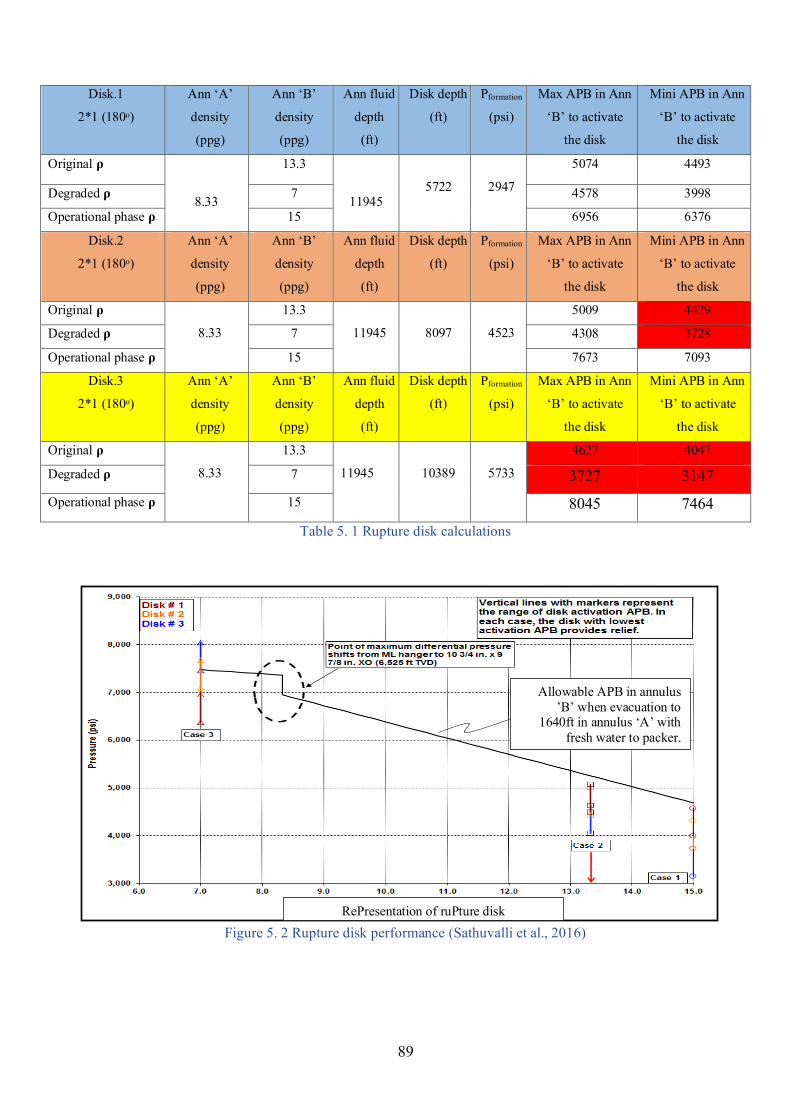
89
Disk.1
2*1 (180ᵒ)
Ann ‘A’
density
(ppg)
Ann ‘B’
density
(ppg)
Ann fluid
depth
(ft)
Disk depth
(ft)
Pformation
(psi)
Max APB in Ann
‘B’ to activate
the disk
Mini APB in Ann
‘B’ to activate
the disk
Original ρ
8.33
13.3
11945
5722
2947
5074 4493
Degraded ρ 7 4578 3998
Operational phase ρ 15 6956 6376
Disk.2
2*1 (180ᵒ)
Ann ‘A’
density
(ppg)
Ann ‘B’
density
(ppg)
Ann fluid
depth
(ft)
Disk depth
(ft)
Pformation
(psi)
Max APB in Ann
‘B’ to activate
the disk
Mini APB in Ann
‘B’ to activate
the disk
Original ρ
8.33
13.3
11945
8097
4523
5009 4429
Degraded ρ 7 4308 3728
Operational phase ρ 15 7673 7093
Disk.3
2*1 (180ᵒ)
Ann ‘A’
density
(ppg)
Ann ‘B’
density
(ppg)
Ann fluid
depth
(ft)
Disk depth
(ft)
Pformation
(psi)
Max APB in Ann
‘B’ to activate
the disk
Mini APB in Ann
‘B’ to activate
the disk
Original ρ
8.33
13.3
11945
10389
5733
4627 4047
Degraded ρ 7 3727 3147 Operational phase ρ 15 8045 7464
Table 5. 1 Rupture disk calculations
Figure 5. 2 Rupture disk performance (Sathuvalli et al., 2016)
Allowable APB in annulus ’B’ when evacuation to
1640ft in annulus ‘A’ with
fresh water to packer.
RePresentation of ruPture disk
90
STEP.4
Application of risk analysis associated with the failure of the mitigation system Apply risk analysis associated with the probability of failure of well integrity due to failure of the
mitigation system is applied during unconventional casing design when the mitigation disk failure
to do its function at the worst scenario of selected casing failure. Then set the optimum solution for
each probable failure mode and finally check if the selected parameters (setting depth, annular fluid
densities, mitigation device activation pressure, and allowable APB) are satisfied?
1- Application of risk analysis The risk analysis applied in both qualitative and quantitative analysis as follows
1-A- Qualitative risk analysis
1-A-I- Hazard identification (HAZID) First define the annulus system, as discussed previously the scenario of casing design show a failure
in production casing by collapse load failure, so the protection system must be installed in annulus
‘B’ to provide bleeding and pressure equilibrium. The analysis applied for the annuli that production
casing bounded it (Ann ‘B’) to indicate the weakest point, expected failure that can be occurred and
performance of the selected mitigation system (Rupture disk).
The geometrical composition of Ann ‘B’ as shown previously in Figure 5.1 that product from casing
design, can be described as:
- Annulus side boundary (inner production casing 10¾in. – outer intermediate casing13⅜in. with
single cement sheath).
- Annulus upper boundary (wellhead seals).
- Annulus lower boundary (open formation).
- Annulus protection system (Rupture disk).
1-A-II- FMEA analysis By using the standard risk matrix as shown in Table 5.2, and apply the analysis made by failure
mode effects analysis (FMEA) for the mitigation device applied, the products are shown in the
Table 5.3.
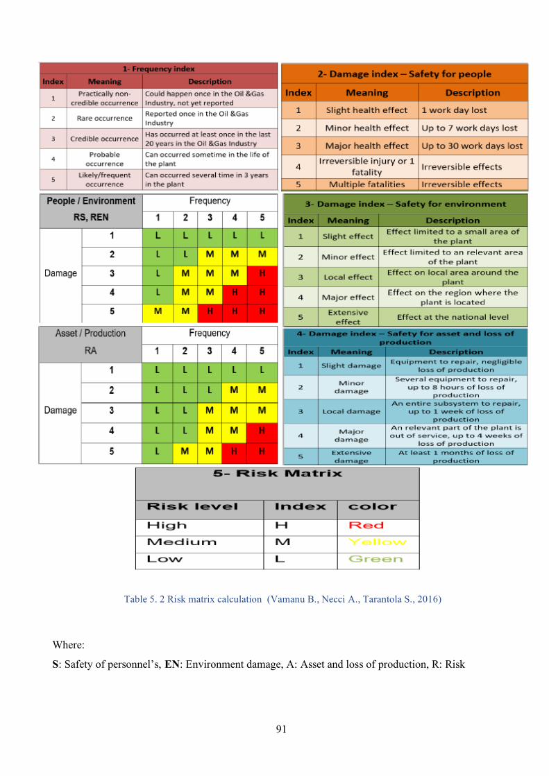
91
Table 5. 2 Risk matrix calculation (Vamanu B., Necci A., Tarantola S., 2016)
Where:
S: Safety of personnel’s, EN: Environment damage, A: Asset and loss of production, R: Risk
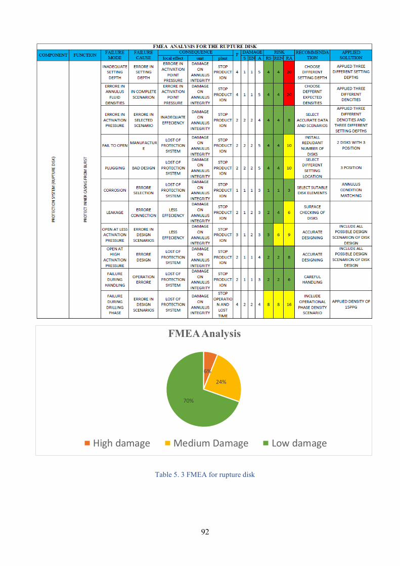
92
Table 5. 3 FMEA for rupture disk
6%
24%
70%
FMEA Analysis
High damage Medium Damage Low damage
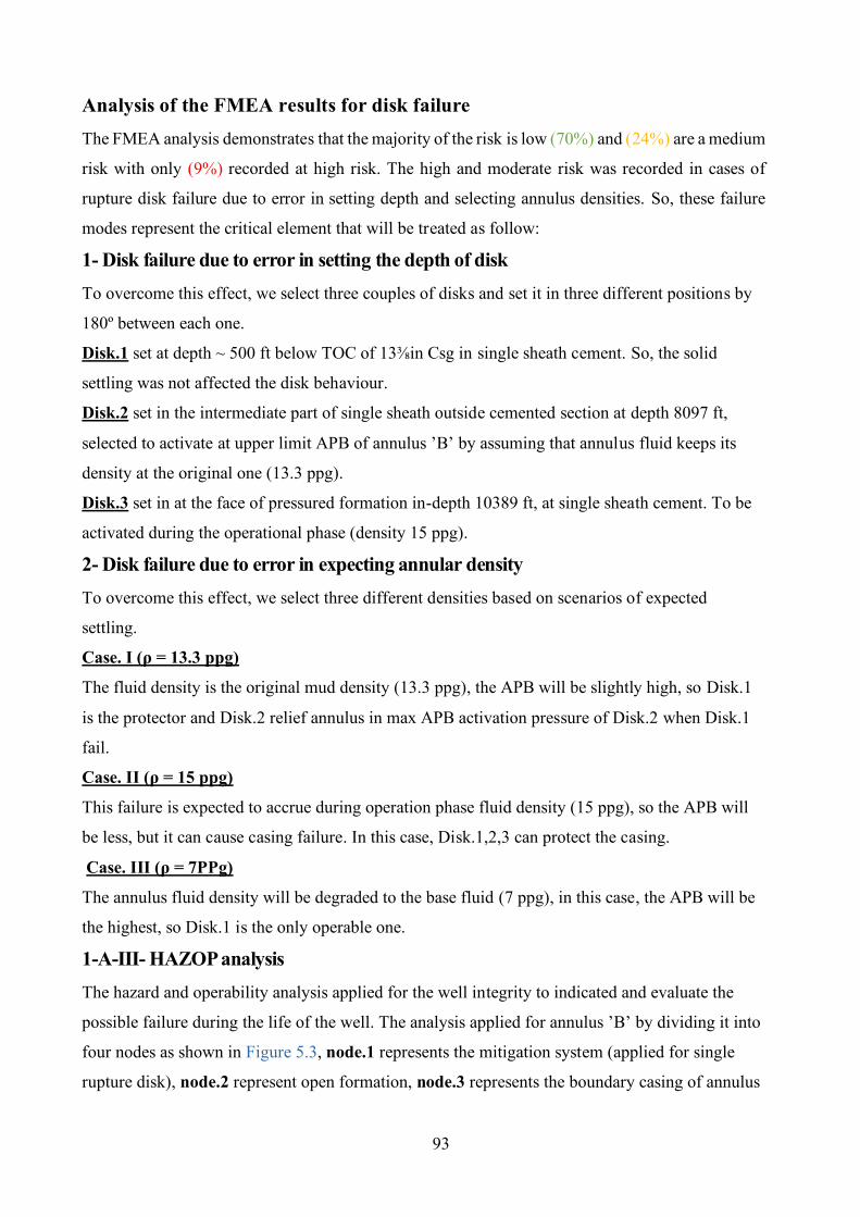
93
Analysis of the FMEA results for disk failure The FMEA analysis demonstrates that the majority of the risk is low (70%) and (24%) are a medium
risk with only (9%) recorded at high risk. The high and moderate risk was recorded in cases of
rupture disk failure due to error in setting depth and selecting annulus densities. So, these failure
modes represent the critical element that will be treated as follow:
1- Disk failure due to error in setting the depth of disk To overcome this effect, we select three couples of disks and set it in three different positions by
180º between each one.
Disk.1 set at depth ~ 500 ft below TOC of 13⅜in Csg in single sheath cement. So, the solid
settling was not affected the disk behaviour.
Disk.2 set in the intermediate part of single sheath outside cemented section at depth 8097 ft,
selected to activate at upper limit APB of annulus ’B’ by assuming that annulus fluid keeps its
density at the original one (13.3 ppg).
Disk.3 set in at the face of pressured formation in-depth 10389 ft, at single sheath cement. To be
activated during the operational phase (density 15 ppg).
2- Disk failure due to error in expecting annular density To overcome this effect, we select three different densities based on scenarios of expected
settling.
Case. I (ρ = 13.3 ppg)
The fluid density is the original mud density (13.3 ppg), the APB will be slightly high, so Disk.1
is the protector and Disk.2 relief annulus in max APB activation pressure of Disk.2 when Disk.1
fail.
Case. II (ρ = 15 ppg)
This failure is expected to accrue during operation phase fluid density (15 ppg), so the APB will
be less, but it can cause casing failure. In this case, Disk.1,2,3 can protect the casing.
Case. III (ρ = 7PPg)
The annulus fluid density will be degraded to the base fluid (7 ppg), in this case, the APB will be
the highest, so Disk.1 is the only operable one.
1-A-III- HAZOP analysis The hazard and operability analysis applied for the well integrity to indicated and evaluate the
possible failure during the life of the well. The analysis applied for annulus ’B’ by dividing it into
four nodes as shown in Figure 5.3, node.1 represents the mitigation system (applied for single
rupture disk), node.2 represent open formation, node.3 represents the boundary casing of annulus
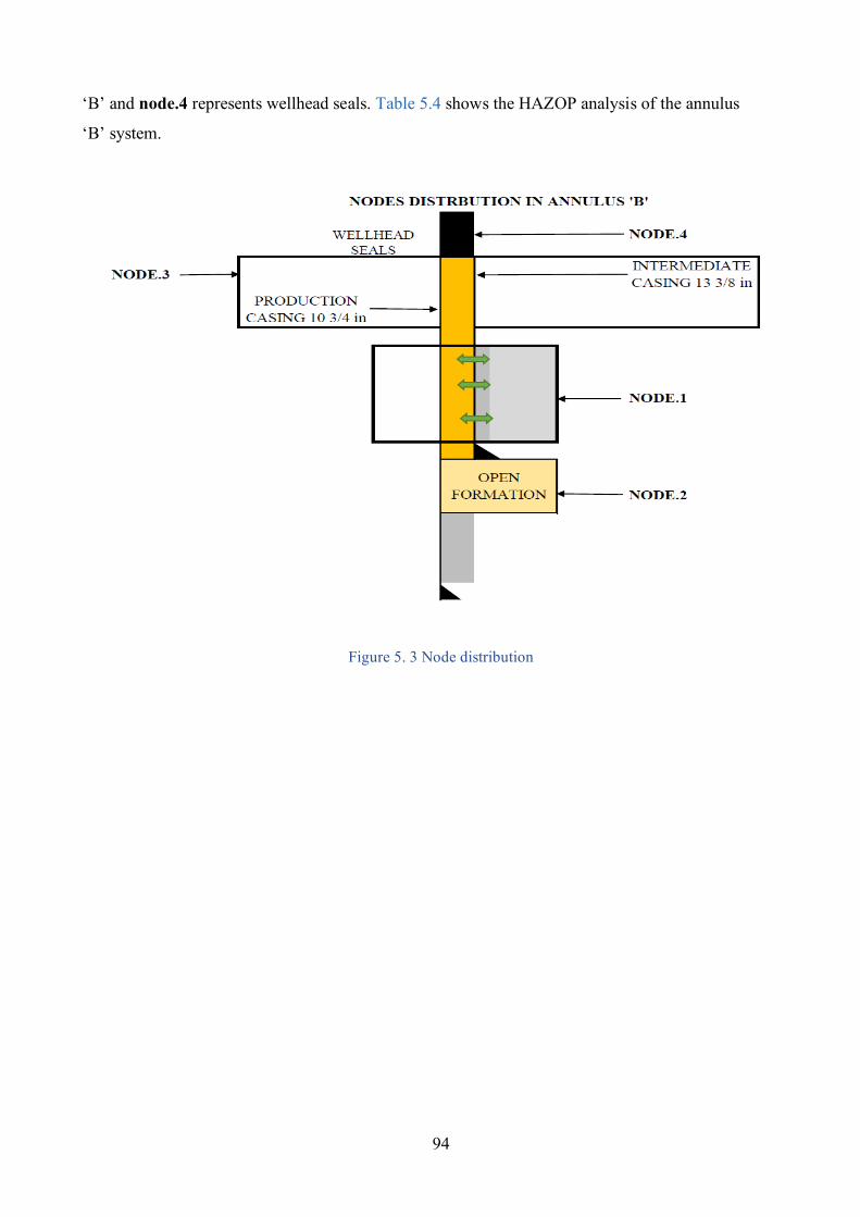
94
‘B’ and node.4 represents wellhead seals. Table 5.4 shows the HAZOP analysis of the annulus
‘B’ system.
Figure 5. 3 Node distribution
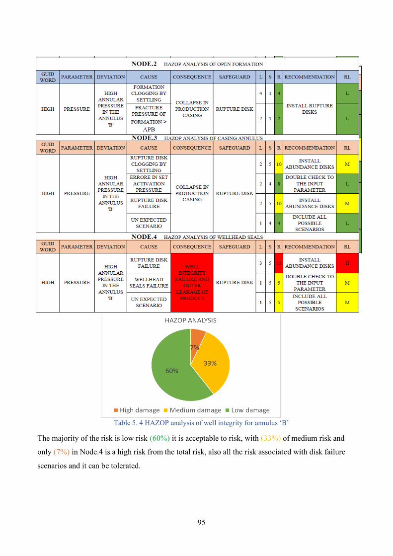
95
Table 5. 4 HAZOP analysis of well integrity for annulus ‘B’
The majority of the risk is low risk (60%) it is acceptable to risk, with (33%) of medium risk and
only (7%) in Node.4 is a high risk from the total risk, also all the risk associated with disk failure
scenarios and it can be tolerated.
96
1-B- Quantitative risk analysis Due to a lack of failure data so, we less trust the quantitative analysis. This analysis was built on
industrial data from manufacturing companies and test laboratories. We concentrate on the failure
of the rupture disk as indicated by HAZOP analysis that shows the possibility of system failure due
to disk failure.
1-B-I- Availability of mitigation system The availability (A(t)) of the mitigation system explained as
Success criteria are venting annular pressure on demand in case of APB > Allowable annular
pressure.
The unavailability (Q(t)) of the mitigation system
The top Event is not venting annular pressure on demand.
Assumptions • Single disk per position (from the couple) is sufficient to control abnormal annular pressure and
protect production casing, so we need to fail both two disks (couple) that installed in the same depth
(180º in between) to make a system failure for the selected annular density and depth.
• All the mitigation system sets (depths of each couple disks) are needs for control APB.
• Life of plant (well) is 20 years (175680 h).
1-B-II- Reliability of mitigation system (Rupture disk)
The reliability (R(t)) of the mitigation system explained as
Success criteria are continuous operations to control the annular pressure for 20 years.
The unreliability (F(t)) of the mitigation system
The top Event is not able to control abnormal annular pressure for 20 years. Assumptions:
• Single disks per position (from the couple) are sufficient to control abnormal annular pressure and
protect production casing, so we need to fail both two disks that are installed in the same depth
(180º in between) to make a system failure for the selected annular density.
• All the mitigation system sets (depths of each couple disks) are needs for control APB. As
expected of different annular fluid density and the effect of settling.
• Life of plant (well) is 20 years (175680 h).
* Because of the mitigation system applied is rupture disk and it is unrepairable, so the reliability
equal to the availability so we develop one and it will equal to the other.
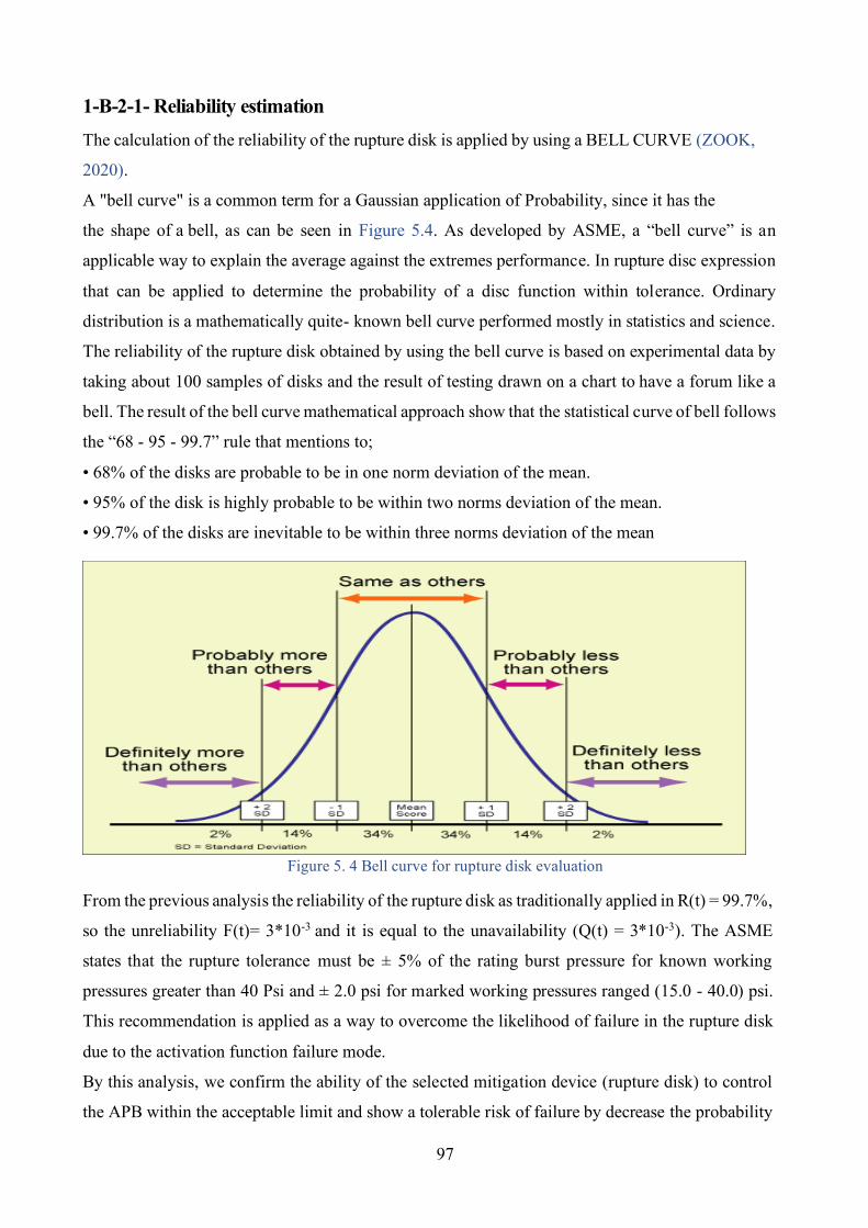
97
1-B-2-1- Reliability estimation The calculation of the reliability of the rupture disk is applied by using a BELL CURVE (ZOOK,
2020).
A "bell curve" is a common term for a Gaussian application of Probability, since it has the
the shape of a bell, as can be seen in Figure 5.4. As developed by ASME, a “bell curve” is an
applicable way to explain the average against the extremes performance. In rupture disc expression
that can be applied to determine the probability of a disc function within tolerance. Ordinary
distribution is a mathematically quite- known bell curve performed mostly in statistics and science.
The reliability of the rupture disk obtained by using the bell curve is based on experimental data by
taking about 100 samples of disks and the result of testing drawn on a chart to have a forum like a
bell. The result of the bell curve mathematical approach show that the statistical curve of bell follows
the “68 - 95 - 99.7” rule that mentions to;
• 68% of the disks are probable to be in one norm deviation of the mean.
• 95% of the disk is highly probable to be within two norms deviation of the mean.
• 99.7% of the disks are inevitable to be within three norms deviation of the mean
Figure 5. 4 Bell curve for rupture disk evaluation
From the previous analysis the reliability of the rupture disk as traditionally applied in R(t) = 99.7%,
so the unreliability F(t)= 3*10-3 and it is equal to the unavailability (Q(t) = 3*10-3). The ASME
states that the rupture tolerance must be ± 5% of the rating burst pressure for known working
pressures greater than 40 Psi and ± 2.0 psi for marked working pressures ranged (15.0 - 40.0) psi.
This recommendation is applied as a way to overcome the likelihood of failure in the rupture disk
due to the activation function failure mode.
By this analysis, we confirm the ability of the selected mitigation device (rupture disk) to control
the APB within the acceptable limit and show a tolerable risk of failure by decrease the probability
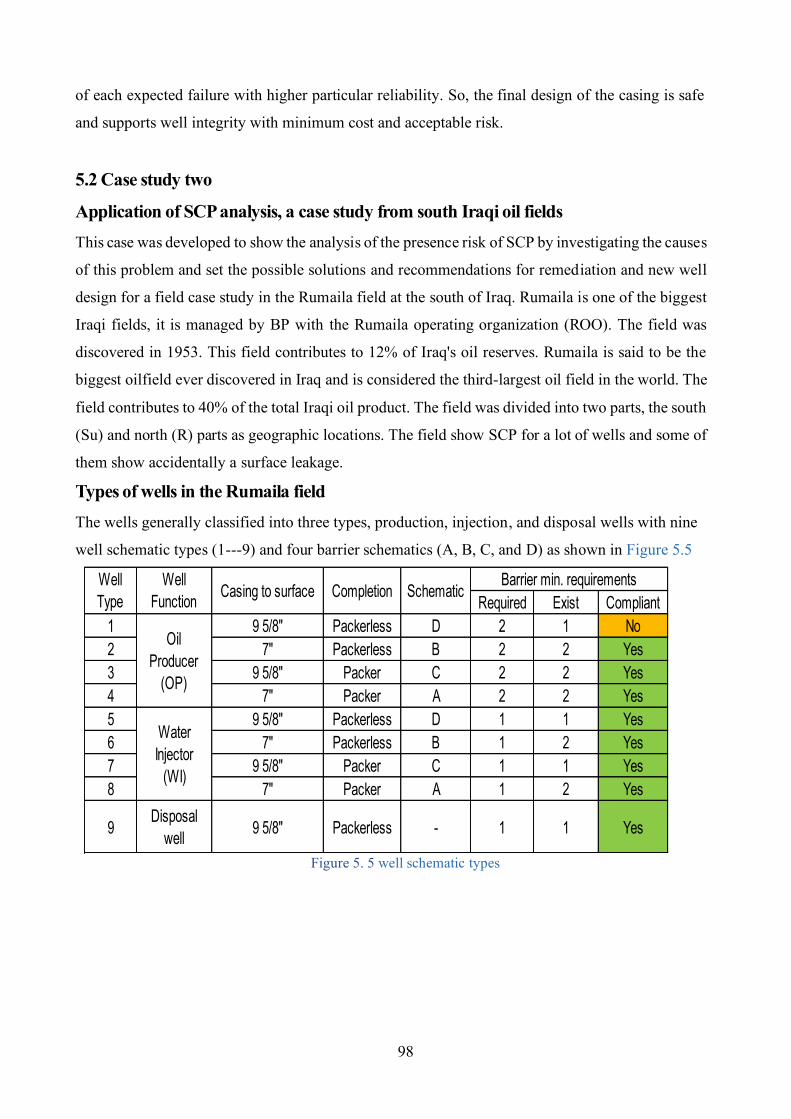
98
of each expected failure with higher particular reliability. So, the final design of the casing is safe
and supports well integrity with minimum cost and acceptable risk.
5.2 Case study two
Application of SCP analysis, a case study from south Iraqi oil fields This case was developed to show the analysis of the presence risk of SCP by investigating the causes
of this problem and set the possible solutions and recommendations for remediation and new well
design for a field case study in the Rumaila field at the south of Iraq. Rumaila is one of the biggest
Iraqi fields, it is managed by BP with the Rumaila operating organization (ROO). The field was
discovered in 1953. This field contributes to 12% of Iraq's oil reserves. Rumaila is said to be the
biggest oilfield ever discovered in Iraq and is considered the third-largest oil field in the world. The
field contributes to 40% of the total Iraqi oil product. The field was divided into two parts, the south
(Su) and north (R) parts as geographic locations. The field show SCP for a lot of wells and some of
them show accidentally a surface leakage.
Types of wells in the Rumaila field The wells generally classified into three types, production, injection, and disposal wells with nine
well schematic types (1---9) and four barrier schematics (A, B, C, and D) as shown in Figure 5.5
Figure 5. 5 well schematic types
Required Exist Compliant1 9 5/8" Packerless D 2 1 No2 7" Packerless B 2 2 Yes3 9 5/8" Packer C 2 2 Yes4 7" Packer A 2 2 Yes5 9 5/8" Packerless D 1 1 Yes6 7" Packerless B 1 2 Yes7 9 5/8" Packer C 1 1 Yes8 7" Packer A 1 2 Yes
9 Disposal well 9 5/8" Packerless - 1 1 Yes
Oil Producer
(OP)
WaterInjector
(WI)
Well Type Schematic Barrier min. requirementsWell
Function Casing to surface Completion
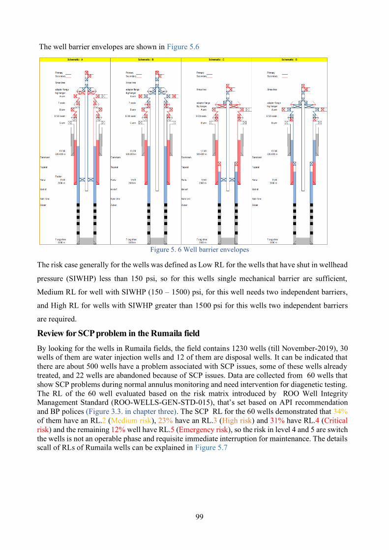
99
The well barrier envelopes are shown in Figure 5.6
Figure 5. 6 Well barrier envelopes
The risk case generally for the wells was defined as Low RL for the wells that have shut in wellhead
pressure (SIWHP) less than 150 psi, so for this wells single mechanical barrier are sufficient,
Medium RL for well with SIWHP (150 – 1500) psi, for this well needs two independent barriers,
and High RL for wells with SIWHP greater than 1500 psi for this wells two independent barriers
are required.
Review for SCP problem in the Rumaila field By looking for the wells in Rumaila fields, the field contains 1230 wells (till November-2019), 30 wells of them are water injection wells and 12 of them are disposal wells. It can be indicated that there are about 500 wells have a problem associated with SCP issues, some of these wells already treated, and 22 wells are abandoned because of SCP issues. Data are collected from 60 wells that show SCP problems during normal annulus monitoring and need intervention for diagenetic testing. The RL of the 60 well evaluated based on the risk matrix introduced by ROO Well Integrity Management Standard (ROO-WELLS-GEN-STD-015), that’s set based on API recommendation and BP polices (Figure 3.3. in chapter three). The SCP RL for the 60 wells demonstrated that 34% of them have an RL.2 (Medium risk), 23% have an RL.3 (High risk) and 31% have RL.4 (Critical risk) and the remaining 12% well have RL.5 (Emergency risk), so the risk in level 4 and 5 are switch the wells is not an operable phase and requisite immediate interruption for maintenance. The details scall of RLs of Rumaila wells can be explained in Figure 5.7
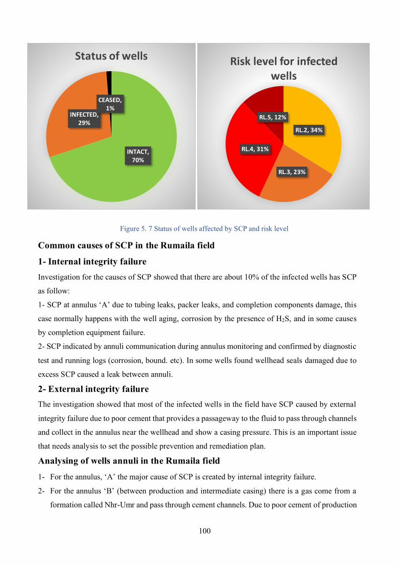
100
Figure 5. 7 Status of wells affected by SCP and risk level
Common causes of SCP in the Rumaila field
1- Internal integrity failure Investigation for the causes of SCP showed that there are about 10% of the infected wells has SCP
as follow:
1- SCP at annulus ‘A’ due to tubing leaks, packer leaks, and completion components damage, this
case normally happens with the well aging, corrosion by the presence of H2S, and in some causes
by completion equipment failure.
2- SCP indicated by annuli communication during annulus monitoring and confirmed by diagnostic
test and running logs (corrosion, bound. etc). In some wells found wellhead seals damaged due to
excess SCP caused a leak between annuli.
2- External integrity failure The investigation showed that most of the infected wells in the field have SCP caused by external
integrity failure due to poor cement that provides a passageway to the fluid to pass through channels
and collect in the annulus near the wellhead and show a casing pressure. This is an important issue
that needs analysis to set the possible prevention and remediation plan.
Analysing of wells annuli in the Rumaila field
1- For the annulus, ‘A’ the major cause of SCP is created by internal integrity failure.
2- For the annulus ‘B’ (between production and intermediate casing) there is a gas come from a
formation called Nhr-Umr and pass through cement channels. Due to poor cement of production
RL.2, 34%
RL.3, 23%
RL.4, 31%
RL.5, 12%
Risk level for infected wells
INTACT, 70%
INFECTED, 29%
CEASED, 1%
Status of wells
101
casing or in some cases the gas comes from the pay zone.
3- Also, For the annulus ‘B’, the gas can come from the pay zone (Mishrif formation or Zubair
formation).
4- For the annulus ‘C’ (between the surface and intermediate casing) in the production and injection
wells, due to the setting of the surface casing at the top of Dammam formation and this formation
is a weak formation, so almost the oil stations (degassers) used this formation for injection of
the disposal water. For some wells close to this disposal wells there is an indicator of this water
collected at the annulus, it can cause casing corrosion and developed for annulus communication
as a result of casing damage.
5- Also, for the annulus ‘C’ for production and injection wells, the intermediate casing mostly
passes through a formation called Tayarat that contains Sulphur water, it will pass through
channels of cement for poor cement and increase the casing corrosion. It may provide new holes
and annulus communication. Also, the sulphur water causes a cement failure due to the pollution
of cement.
- Normal annulus monitoring and diagnostic reports The routine annulus monitoring is carried out as programmed and casing pressure measured at
production annulus (annulus ‘A’) and other annuli (‘B’, ‘C’...etc) as planned previously by the
operator, the recorded results are indicating an abnormal annular pressure. The operator is alarmed
by the unacceptable risk level and suggests applying the annulus investigation and pressure test to
analyse the cause of this pressure. In general, for the total wells in this field, the plan was made to
review the existing designs and analyse for the causes of SCP in these wells with possible
modifications and recommendations.
- Well design review The data used for analysing completion and drilling designs are collected from some infected wells
in the fields that recorded SCP during monitoring and compared with other intact wells. The base
data are collected from the end well report for completion and workover operations that are:
- Well Kill Data & Chart (Killing fluids and pressure records) The analysis shows
* The effect of neighbouring annuli during killing well (annuli linking) almost found due to
wellhead sealing damage. In few wells found due to casing damage, confirmed by performing logs,
so the analysis of annulus fluid shows corrosive materials (oil, gas, sulphur water), and the source
of these fluids is defined as logs records and type of fluid that match the known formation source.
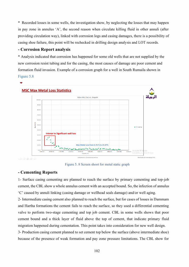
102
* Recorded losses in some wells, the investigation show, by neglecting the losses that may happen
in pay zone in annulus ‘A’, the second reason when circulate killing fluid in other annuli (after
providing circulation way), linked with corrosion logs and casing damages, there is a possibility of
casing shoe failure, this point will be rechecked in drilling design analysis and LOT records.
- Corrosion Report analysis * Analysis indicated that corrosion has happened for some old wells that are not supplied by the
new corrosion resist tubing and for the casing, the most causes of damage are poor cement and
formation fluid invasion. Example of a corrosion graph for a well in South Rumaila shown in
Figure 5.8
Figure 5. 8 Screen shoot for metal static graph
- Cementing Reports 1- Surface casing cementing are planned to reach the surface by primary cementing and top-job
cement, the CBL show a whole annulus cement with an accepted bound. So, the infection of annulus
‘C’ caused by annuli linking (casing damage or wellhead seals damage) and/or well aging.
2- Intermediate casing cement also planned to reach the surface, but for cases of losses in Dammam
and Hartha formations the cement fails to reach the surface, so they used a differential cementing
valve to perform two-stage cementing and top job cement. CBL in some wells shows that poor
cement bound and a thick layer of fluid above the top of cement, that indicate primary fluid
migration happened during cementation. This point takes into consideration for new well design.
3- Production casing cement planned to set cement top below the surface (above intermediate shoe)
because of the presence of weak formation and pay zone pressure limitations. The CBL show for
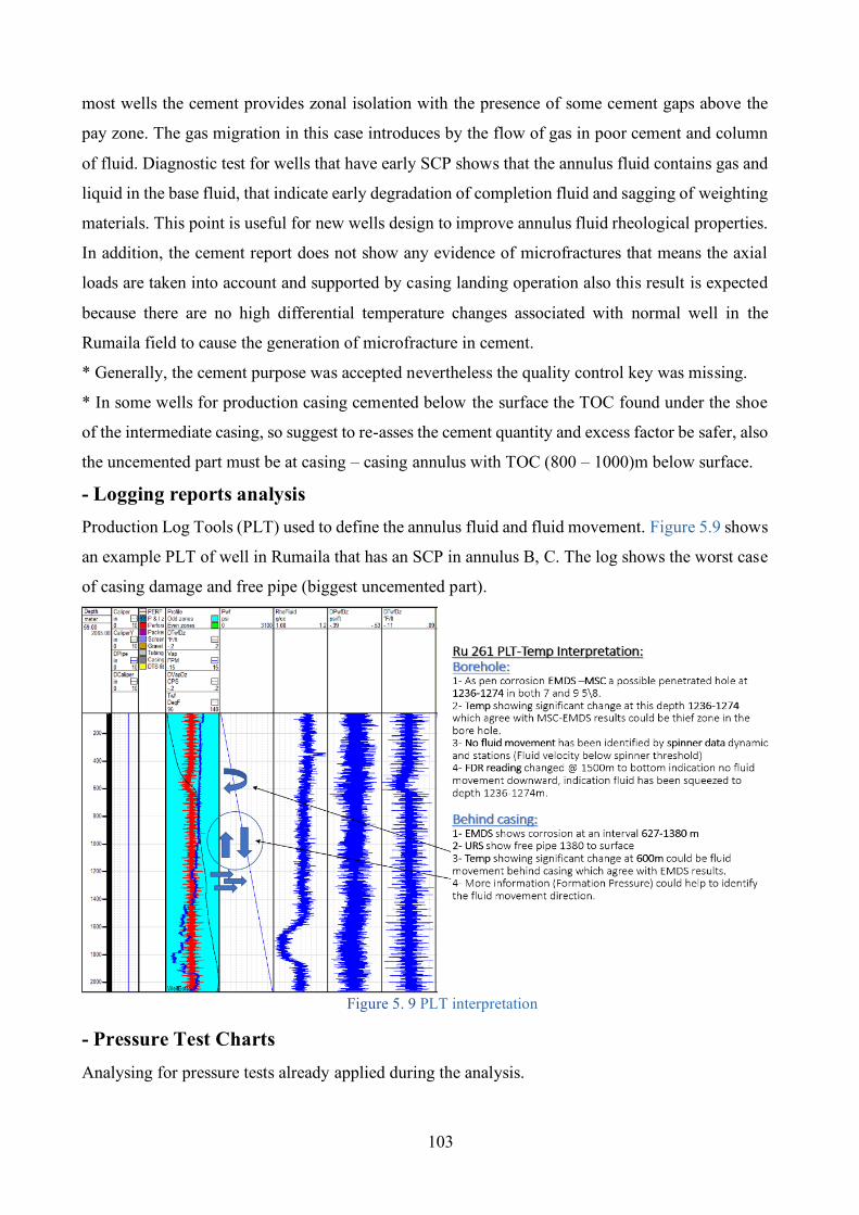
103
most wells the cement provides zonal isolation with the presence of some cement gaps above the
pay zone. The gas migration in this case introduces by the flow of gas in poor cement and column
of fluid. Diagnostic test for wells that have early SCP shows that the annulus fluid contains gas and
liquid in the base fluid, that indicate early degradation of completion fluid and sagging of weighting
materials. This point is useful for new wells design to improve annulus fluid rheological properties.
In addition, the cement report does not show any evidence of microfractures that means the axial
loads are taken into account and supported by casing landing operation also this result is expected
because there are no high differential temperature changes associated with normal well in the
Rumaila field to cause the generation of microfracture in cement.
* Generally, the cement purpose was accepted nevertheless the quality control key was missing.
* In some wells for production casing cemented below the surface the TOC found under the shoe
of the intermediate casing, so suggest to re-asses the cement quantity and excess factor be safer, also
the uncemented part must be at casing – casing annulus with TOC (800 – 1000)m below surface.
- Logging reports analysis Production Log Tools (PLT) used to define the annulus fluid and fluid movement. Figure 5.9 shows
an example PLT of well in Rumaila that has an SCP in annulus B, C. The log shows the worst case
of casing damage and free pipe (biggest uncemented part).
Figure 5. 9 PLT interpretation
- Pressure Test Charts Analysing for pressure tests already applied during the analysis.
104
- Well Schematic, updated during well life Will be covered in drilling design analysis. Analysing for casing setting depth and expected hole
problem that affects annulus integrity during the well life cycle.
- ESP Running Report Analysing for ending report for some wells show, No effect for SCP due to the presence of ESP.
- Completion of fluid report Anti-corrosion completion fluid is used, and no gaps are found in this issue.
- Analysis of casing design The analysis of casing design show that the design built on the approach of” Maximum load
concept”, which consist of:
Burst load design, Collapse load design, Tension load design, Buckling and wellhead loads design
Analysis of these details indicates that the currently used casing design for the production and
injection wells are meet the required load-bearing, and SCP problems in most cases related to that
the designer supposes that target TOC provided by primary cementation or top job cementing can
decrease the effects of casing wearing, cost of cement, and by decrease the pressure of cement slurry
head to reach optimum TOC. But the evidence of cement bond breakdown in some cases due to
poor cement and early well aging refers to that some cases have not adequate TOC. The evidence
of cement evaluation leads to conclude that there is a secondary gas migration in the annulus ‘B’ by
channels in cement. To suggest that casing must be cemented as close to the surface as possible to
prevent formation fluids migration, decrease annulus space for migrated fluids accommodation, and
provide more support to the casing.
- Design improving recommendations To avoid and mitigate the effect of SCP the process applied by improving the well design with some
recommendations as follows:
1- Removed all the presence gas of drilled formations (gas pockets) before cementing, especially
for Nhr-Umr formation and production zones. Applied final circulation before cementing carefully
and check mud return and acid concentration.
2- The hydrostatic pressure of cement while the time of solidification to control the formation of
fluid migration must be kept at less equal to the gradient of mud applied during drilling till the
cement built the sufficient bound.
3- Application of a “mud-filled” packer for the outer annulus, should be used above the zone that
has a high possibility of fluid migration or unable to perform success cement job (intermediate
105
casing cementing) to isolate this formation then perform a secondary cement job, as successfully
applied by Weatherford company in Rumaila field at intermediate casing to isolate sulphur water.
4- During the displacement of cement it suggested using a fluid with weight the same as the weight
of the fluid that will be used for the next hole.
5- Annulus fluid for annuli cemented below the surface must be treated carefully for corrosion and
sagging.
6- Losses when occurred must be treated before cementing operation and ensure the well is
controlled and stable. As recorded, there is partial to complete losses in the second and third holes.
7- Primary gas migration can be avoided by improving cement slurry characterization, cementing
operation, displacement mechanism. Secondary gas migration can be avoided by providing a
suitable buckling design for the casing to prevent the generation of microcracks.
8- After performing CBL before production, if the result shows poor cement, open discussion, and
set possible remediation before perforating the well and start production to prevent SCP
development.
9- It is recommended to perform a nitrified cement job for the new well's design for the section of
field that has well records a high severity of SCP. The cost of applying a lot of remediation jobs,
production interruption, costed operation and early abounded of wells (as indicated from analysis
most of the remediation jobs are useless) are high relative to nitrified cement job.
Remediation recommendations When the maintenance and fixing must be applied outside of the production casing, the operation
becomes technically hard and costly. So, remediation for the wells of SCP problem due to external
integrity failure is very difficult and depend on the type of well and production casing size as follow
1- Wells with 7 in. casing to the surface The remediation reports show that about 70% of remediation for the well that has 7in. production
casing is failed because of un ability to perform cement remediation jobs due to damage and weak
casing caused by high corrosion resulted by contacting of corroded fluid or well aging, the problem
for these wells that not show a risk case of SCP in the primary time of well age because of the
contaminate fluid has relatively low pressure but when the case developed, casing damage, annulus
linking, or annular fluid settling accrued, the casing pressure increased and inter the high RL. For
that reason, we suggest checking the cement bound quality and make cement remediation before
start production and each time of work over. In this case, the most acceptable method for SCP risk
treatment is by following the periodic bleeding of excessive pressure. It is crucial to pay attention to
that some operators considered the procedure of periodic bleed-off will increase the severity of the SCP
level. Otherwise, other operators consider that periodic bleeding provides a temporary limit to the
106
severity of the SCP problem. The BP operators apply this method to control the severity of SCP problem
for the wells that have MAASP very low (less than required injection pressure of work over operation),
remediate low SCP, relief high SCP temporarily and for wells with severity casing damage or at the end
of production life age. Another remediation method is by lubrication in weighted brine or mud for the
cases that permit pressure injection on the annulus.
2- Wells with 9⅝ in. casing to the surface The analysis of case wells showed that this type has the more ability to perform remediation jobs
due to the presence of tie-back option, most remediation jobs for casing and cement remedial are
successful applied for this type. Based on MAASP for annuli, the operator as can be indicated by
analysis can apply a lot of remediation methods (as discussed in risk analysis in chapter three).
3- Abandoned wells It is a long-term study and analysis, the decision makes finally when the well case is threatening the
safety production and environment standard. These types need more analysis and more check when
the MAASP reached zero psi that means the remediation operation has to be applied without any
pressure this challenge in most cases (as per the study) lead to abandoned the well and by this state,
the well also follows the safety standard for isolation and closing with ensuring the presence of
barrier sufficient to still the well secure and timely observation will be programmed to observe well
and check for any unexpected seals failure. Besides there are some justification must be found and
analysed before well abandoned, such as reached the end of the production plan, there are high
damage and unbenefited for apply remediation, change in well functionality required with the
situation of well cannot satisfied and when there is high risk and cannot be treated.
107
CONCLUSION
I- Deepwater HPHT and SSW design must consider the thermal effect by providing scenarios for
all expected cases related to operations and functions of well for all service life cycle.
II- The target of reaching or maintain annular pressure equal to zero is not the best choice in all
cases, it is enough to maintain annular pressure under the permissible limit and keep the cost.
III- Cement quality must be confirmed and fluid movement behind the casing must be checked
before the well start-up, also applied for any work over interruption, to prevent or reduce the
chance of SCP accruing.
IV- Rupture disk is the more accepted mitigation technique, due to it is lower cost, reliability
improvement, and easier operation, also it preferred because of the APB threat the outer annuli
due to high-temperature difference and the outer annuli have a single cement sheath the two
favourable conditions for rupture disk application.
V- TAP for the normal annulus distribution of deep-water HPHT wells tend to threaten the
collapse resistance of the inner casing of annulus than the burst of the outer one, so the application
of TAP mitigation must concentrate on the intermediate casing and back saving the production
casing.
VI- The temperature profile of SSW must be modified during well life due to a change in
production rate and produced fluid composition that affects PVT properties of the annular fluid.
VII- The final selected mitigation device must be able to protect well integrity from all possible
failure scenarios by TAP, treat all expected risks, have optimum cost (supply, operation, and
performance), higher reliability (even if it is improved), support the expected functionality
changing of well and protecting the environment.
VIII- By organizing mitigation techniques in terms of cost, time, and operation we recommended
using Rupture Disks, Nitrified Spacers, IPF, Syntactic Foams, and VIT.
IX- Allowable annular pressure must be set first during design then updated as the change in
MAASP and MAWOP by derating factor due to well aging.
108
X- When well functionality changed (transfer from production to another function), design
review must apply and introduce new scenarios with new risk analysis based on annular pressure
state permissible limits and last records of (CBL, Corrosion, workover, temperature, and pressure
profile) to test the feasibility of applying the new activity.
XI- For the wells that suspect to develop complex abnormal annular pressure, suggested applying
nitrified spacer technology to mitigate TAP & SCP at the same time.
XII- The probability of cement channeling by formation fluids during migration from higher to
lower pressure formation is increased if the setting depth of casing elongated by drilling ahead
with drilling fluids densities close to reaching the top-hole formation fracture equivalent density.
109
BIBLOGRAPHY Adams, A. (1991). How to design for annulus fluid heat-up. Proceedings - SPE Annual Technical Conference and Exhibition, Pi(pt 2), 529–540. https://doi.org/10.2118/22871-ms
Ajayi, A., Mamman, S., Agbahara, C., Udo, N., Karunwi, A., & Ogunsina, O. (2014). Holistic annulus investigation as a tool to assure well integrity in a deep water environment. 38th Nigeria Annual International Conference and Exhibition, NAICE 2014 - Africa’s Energy Corridor: Opportunities for Oil and Gas Value Maximization Through Integration and Global Approach, 1, 713–722. https://doi.org/10.2118/172408-ms
Ansari, J. S., Teodoriu, C., & Sun, Y. (2014). Evaluation of Annular Pressure Buildup (APB) during WCD Blowout of Deepwater Hp/Ht Wells (Doctoral dissertation). December.
Bellarby, J., Kofoed, S. S., & Marketz, F. (2013). Annular pressure build-up analysis and methodology with examples from multifrac horizontal wells and HPHT reservoirs. SPE/IADC Drilling Conference, Proceedings, 2, 1562–1573. https://doi.org/10.2118/163557-ms
Bloys, B., Gonzalez, M., Hermes, R., Bland, R., Foley, R., Tijerina, R., Davis, J., Cassel, T., Daniel, J., Robinson, I., Billings, F., & Eley, R. (2008). Trapped annular pressure: A spacer fluid that shrinks. JPT, Journal of Petroleum Technology, 60(4), 55–58.
Bourgoyne, A. T., Scott, S. L., & Manowski, W. (2000). A Review of Sustained Casing Pressure Occurring on the OCS. Minerals Management Services, US DOI, 61.
Bradford, D. W., et al. (2002). Marlin failure analysis and redesign: Part 2 - Redesign. SPE Drilling and Completion, 19(2), 112–119. https://doi.org/10.2118/88838-PA
Brown, J., Kenny, N., & Slagmulder, Y. (2016). Unique cement design to mitigate trapped annular pressure TAP between two casing strings in steam injection wells. Society of Petroleum Engineers - SPE Heavy Oil Conference and Exhibition 2016. https://doi.org/10.2118/184102-ms
Calcada, L. A., Scheid, C. M., Da Cruz Meleiro, L. A., Oechsler, B. F., Fagundes, F. M., Santos, N. B. C., De Oliveira Arouca, F., Damasceno, J. J. R., Souza, E., Waldmann, A. T., & Martins, A. L. (2017). Designing fluid properties to minimize barite sag and its impact on annular pressure build up mitigation in producing offshore wells. OTC Brasil 2017, 869–877. https://doi.org/10.4043/28052-ms
Calçada, L. A., Scheid, C. M., Meleiro, L. A. C., Ribeiro, J. M., Seufitelli, G. V. S., Peliano, S. V., Santos, H. F. L., Souza, E. A., Monteiro, V., & Martins, A. L. (2016). Barite Sag and Its Impact On Annular Pressure Build Up Mitigation In Producing Offshore Wells. https://doi.org/10.2118/181377-ms
Carpenter, R. B., Gonzalez, M. E., Granberry, V., & Becker, T. E. (2004). Remediating sustained casing pressure by forming a downhole annular seal with low-melt-point eutectic metal. Proceedings of the Drilling Conference, 849–863. https://doi.org/10.2118/87198-ms
110
Dong, G., & Chen, P. (2017). A review of the evaluation methods and control technologies for trapped annular pressure in deepwater oil and gas wells Journal of Natural Gas Science and Engineering A review of the evaluation methods and control technologies for trapped annular pressure. Journal of Natural Gas Science and Engineering, 37(November 2016), 85–105. https://doi.org/10.1016/j.jngse.2016.11.042
Dusterhoft, D., Wilson, G., & Newman, K. (2002). Field Study on the Use of Cement Pulsation to Control Gas Migration. SPE Gas Technology Symposium Proceedings. https://doi.org/10.2118/75689-ms
Ettehadi Osgouei, R., et al. (2014). Annular pressure build up (APB) analysis-optimization of fluid rheology. Society of Petroleum Engineers - SPE Deepwater Drilling and Completions Conference 2014, m, 66–87. https://doi.org/10.2118/170262-ms
Ezell, R. G., Fontenot, S., Robinson, E., Cunningham, L., & Patrickis, A. (2010). High performance aqueous insulating packer fluid improved flow assurance and reduced annular pressure buildup in ultra deepwater wells. Society of Petroleum Engineers - SPE Deepwater Drilling and Completions Conference 2010, 62–69. https://doi.org/10.2118/135177-ms
Gosch, S. W., Horne, D. J., Pattillo, P. D., Sharp, J. W., & Shah, P. C. (2002). Marlin Failure Analysis and Redesign; Part 3, VIT Completion with Real-Time Monitoring. Proceedings of the Drilling Conference, 557–565. https://doi.org/10.2523/74530-ms
Gouveia, L. P., Lima Junior, E. T., Santos, J. P. L., Lira, W. W. M., Anjos, J. L. R., & Oliveira, F. L. (2020). Probabilistic assessment of API casing strength in serviceability limit state. Journal of Petroleum Exploration and Production Technology, 10(5), 2089–2104. https://doi.org/10.1007/s13202-020-00858-9
Halal, A. S., & Mitchell, R. F. (1994). Casing design for trapped annular pressure buildup. SPE Drilling and Completion, 9(2), 107–114. https://doi.org/10.2118/25694-PA
Halliburton. (2012). Insulating Packer Fluid Reduces Annular Pressure Buildup in Deepwater Well. 9049.
Hasan, A. R., Izgec, B., & Kabir, C. S. (2010). Sustaining production by managing annular-pressure buildup. SPE Production and Operations, 25(2), 195–203. https://doi.org/10.2118/120778-pa
Kang, Y., Gonzales, A., Liu, Z., & Samuel, R. (2017). Modeling and simulation of annular pressure buildup APB in a deepwater wellbore with vacuum-insulated tubing. SPE/IADC Drilling Conference, Proceedings, 2017-March, 1391–1408. https://doi.org/10.2118/184618-ms
Kinik, K., & Wojtanowicz, A. K. (2011). Identifying environmental risk of sustained casing pressure. Society of Petroleum Engineers - SPE Americas E and P Health, Safety, Security, and Environmental Conference 2011, 457–468. https://doi.org/10.2118/143713-ms
Kumar, Amit, Srivastava, M., Abdulhai, W., & Gan, C. L. (2018). Proactive integrity management of aging wells with sustainable annulus pressure sap. Society of Petroleum Engineers - Abu Dhabi International Petroleum Exhibition and
111
Conference 2018, ADIPEC 2018.
Kumar, Animesh, Gillies, J., Mehra, R., Pardeshi, M., Wilke, A., & Li, J. (2017). Improved primary cement jobs and mitigation of sustained casing pressure through the use of foamed spacer design technology. SPE/IADC Drilling Conference, Proceedings, 2017-March, 925–943. https://doi.org/10.2118/184605-ms
Kutchko, B., Crandall, D., Moore, J., Gill, M., Haljasmaa, I., Spaulding, R., Harbert, W., Benge, G., DeBruijn, G., & Shine, J. (2014). Assessment of foamed cement used in deep offshore wells. Society of Petroleum Engineers - SPE Deepwater Drilling and Completions Conference 2014, 372–391. https://doi.org/10.2118/170298-ms
Leach, C. P., & Adams, A. J. (1993). New method for the relief of annular heat-up pressures. Production Operations Symposium, 819–826.
Liu, J., Fan, H., Peng, Q., Deng, S., Kang, B., & Ren, W. (2015). Journal of Natural Gas Science and Engineering Research on the prediction model of annular pressure buildup in subsea wells. Journal of Natural Gas Science and Engineering, 27, 1677–
1683. https://doi.org/10.1016/j.jngse.2015.10.028
Liu, J., Fan, H., Zhu, L., Tian, D., Wen, Z., Liu, Y., & Wang, G. (2017). Development of a transient method on predicting multi-annuli temperature of subsea wells. Journal of Petroleum Science and Engineering, 157, 295–301. https://doi.org/10.1016/j.petrol.2017.06.072
Liu, Z., Samuel, R., Gonzales, A., & Kang, Y.-A. (2016a). Modeling and simulation of annular pressure buildup (APB) mitigation using rupture disk. SPE/IADC Drilling Conference, Proceedings, 2016-Janua, 1–13. https://doi.org/10.2118/178807-ms
Liu, Z., Samuel, R., Gonzales, A., & Kang, Y.-B. (2016b). Modeling and simulation of annular pressure buildup APB management using syntactic foam in HP/HT deepwater wells. Society of Petroleum Engineers - SPE Deepwater Drilling and Completions Conference. https://doi.org/10.2118/180308-ms
Loder, T., Evans, J. H., & Griffith, J. E. (2003). Prediction of and Effective Preventative Solution for Annular Fluid Pressure Buildup on Subsea Completed Wells - Case Study. Proceedings - SPE Annual Technical Conference and Exhibition, 1859–1865. https://doi.org/10.2118/84270-ms
Milanovic, D., & Smith, L. (2005). A case history of sustainable annulus pressure in sour wells - Prevention, evaluation and remediation. Society of Petroleum Engineers - SPE High Pressure/High Temperature Sour Well Design Applied Technology Workshop 2005, HPHT 2005. https://doi.org/10.2118/97597-ms
Miller, R. A., Coy, A., Frank, G., & Dondale, A. (2018). Advancements in APB mitigation for thunder horse wells. SPE/IADC Drilling Conference, Proceedings, 2017-March(May 2017), 714–726. https://doi.org/10.2118/184725-ms
Mwang’Ande, A. W., Liao, H., & Zeng, L. (2019). Management of sustained casing pressure in offshore gas wells by a novel casing-surface design that suppress gas migration at the casing-cement interface. Society of Petroleum Engineers - SPE Gas and Oil Technology Showcase and Conference 2019, GOTS 2019, 1–15.
112
https://doi.org/10.2118/198601-ms
Nishikawa, S., Wojtanowicz, A. K., & Smith, J. R. (2001). Experimental assessment of the bleed-and-lube method for removal of sustained casing pressure. Canadian International Petroleum Conference 2001, CIPC 2001, 1–9. https://doi.org/10.2118/2001-041
NORSOK. (2004). Well Integrity in Drilling and Well Operations. NORSOK Standard D-010, August, 157.
Oudeman, P., & Kerem, M. (2004). Transient behavior of annular pressure build-up in HP/HT wells. 11th ADIPEC: Abu Dhabi International Petroleum Exhibition and Conference - Conference Proceedings, 665–674. https://doi.org/10.2523/88735-ms
Pattillo, P. D., Sathuvalli, U. B., Rahman, S. M., Prewett, H. H., Carmichael, S. P., & Wydrinski, R. (2007). Mad dog slot W1 tubing deformation failure analysis. Proceedings - SPE Annual Technical Conference and Exhibition, 2, 1356–1363. https://doi.org/10.2118/109882-ms
Pattillo, Phillip D., Bellarby, J. E., Ross, G. R., Gosch, S. W., & McLaren, G. D. (2004). Thermal and mechanical considerations for design of insulated tubing. SPE Drilling and Completion, 19(3), 181–188. https://doi.org/10.2118/79870-PA
Pattillo, Phillip D., Cocales, B. W., & Morey, S. C. (2004). Analysis of an annular pressure buildup failure during drill ahead. SPE Drilling and Completion, 21(4), 242–247. https://doi.org/10.2118/89775-pa
Payne, M. L., Pattillo, P. D., Miller, R. A., & Johnson, C. K. (2007). Advanced technology solutions for next generation HPHT wells. International Petroleum Technology Conference 2007, IPTC 2007, 2, 1008–1022. https://doi.org/10.3997/2214-4609-pdb.147.iptc11463
Phi, T., Elgaddafi, R., Al Ramadan, M., Fahd, K., Ahmed, R., & Teodoriu, C. (2019). Well integrity issues: Extreme high-pressure high-temperature wells and geothermal wells a review. Society of Petroleum Engineers - SPE Thermal Well Integrity and Design Symposium 2019, TWID 2019.
Pilko, B., & Tx, U. S. A. (2016). Project Management point of contact is :
Riggs, K. R. e. all. (2001). BEST PRACTICES FOR PREVENTION AND MANAGEMENT OF SUSTAINED CASING PRESSURE.
Rizkiaputra, R., Siregar, R., Wibowo, T., & Mabunga, S. (2016). A new method to mitigate annular pressure buildup by using sacrificial casing, case study: A deepwater well in Indonesia. SPE/IADC Drilling Conference, Proceedings, 2016-Janua. https://doi.org/10.2118/178854-ms
Rocha-Valadez, T., Hasan, A. R., Mannan, S., & Kabir, C. S. (2014). Assessing wellbore integrity in sustained-casing-pressure annulus. SPE Drilling and Completion, 29(1), 131–138. https://doi.org/10.2118/169814-PA
RP, 14B. (1999). ALLOAWBLE LEKAGE RATE AND RELIABILITY OF SAFETY AND
113
POLLUTION PREVENTION EQUIPMENT.
RP, A. (2006). Annular Casing Pressure Management for Offshore Wells. August.
Sangesland, S., Rausand, et all. (2012). An Introduction to Well Integrity. December.
Santos, H. L., Rocha, J. S., Ferreira, M. V., Lima, V., Souza, C. O., Borges, A., & Silva, E. C. (2015). APB mitigation techniques and design procedure. OTC Brasil 2015: The Atlantic: From East to West - An Ocean of Innovation, October, 1979–1991. https://doi.org/10.4043/26294-ms
Sathuvalli, U. B., Payne, M. L., Pattillo, P. D., Rahman, S., & Suryanarayana, P. V. (2005). Development of a screening system to identify deepwater wells at risk for annular pressure build-up. SPE/IADC Drilling Conference, Proceedings, 849–862. https://doi.org/10.2118/92594-ms
Sathuvalli, U. B., Pilko, R. M., Gonzalez, R. A., Pai, R. M., Sachdeva, P., Suryanarayana, P. V, & Energy, B. (2016). Design and Performance of Annular Pressure Build-up ( APB ) Mitigation Production APB loads. 1991.
Suryanarayana, P. V., & Lewis, D. B. (2016). A reliability-based approach for survival design in deepwater and high pressure/high temperature wells. SPE/IADC Drilling Conference, Proceedings, 2016-Janua. https://doi.org/10.2118/178907-ms
Tahmourpour, F., Hashki, K., & Hassan, H. (2010). Different methods to avoid annular pressure buildup by appropriate engineered sealant and appying best practices (cementing and drilling). SPE Drilling and Completion, 25(2), 248–252. https://doi.org/10.2118/110040-pa
Vamanu B., Necci A., Tarantola S., K. E. . (2016). Offshore risk assessment - An overview of methods and tools. Ispra: European Commission,. https://doi.org/10.1007/978-94-017-2471-5
Vargo, R. F., Payne, M., Faul, R., LeBlanc, J., & Griffith, J. E. (2002). Practical and Successful Prevention of Annular Pressure Buildup on the Marlin Project. Proceedings - SPE Annual Technical Conference and Exhibition, 1235–1244. https://doi.org/10.2523/77473-ms
Wang, H., Zhang, H., Li, J., Zeng, Y., Ding, S., & Tao, Q. (2018). Optimization of the annulus nitrogen injection volume in offshore wells with annular pressure buildup. Society of Petroleum Engineers - SPE Kingdom of Saudi Arabia Annual Technical Symposium and Exhibition 2018, SATS 2018, i. https://doi.org/10.2118/192443-ms
Williamson, R., Sanders, W., Jakabosky, T., Serio, M., & Griffith, J. (2007). Control of Contained-Annulus Fluid Pressure Buildup. https://doi.org/10.2523/79875-ms
Wojtanowicz, A. K., Smith, J. R., Novakovic, D., Chimmalgi, V. S., Newman, K. R., Dusterhoft, D., & Gahan, B. (2002). Cement Pulsation Treatment in Wells. Proceedings - SPE Annual Technical Conference and Exhibition, 3581–3596. https://doi.org/10.2118/77752-ms
Xu, R., & Wojtanowicz, A. K. (2003). Diagnostic testing of wells with sustained casing
114
pressure-An analytical approach. Canadian International Petroleum Conference 2003, CIPC 2003. https://doi.org/10.2118/2003-221
Yin, F., & Gao, D. (2014). Improved Calculation of Multiple Annuli Pressure Buildup in Subsea HPHT.
Zhang, B., Guan, Z. C., Wang, Q., Xuan, L. C., Liu, Y., & Sheng, Y. (2016). Appropriate completion to prevent potential damage of annular pressure buildup in deepwater wells. Society of Petroleum Engineers - IADC/SPE Asia Pacific Drilling Technology Conference. https://doi.org/10.2118/180542-MS
Zhang, B., Guan, Z., Hasan, A. R., Lu, N., Wang, Q., Xu, Y., Zhang, Q., & Liu, Y. (2017). Development and design of new casing to mitigate trapped annular pressure caused by thermal expansion in oil and gas wells. 118, 292–298. https://doi.org/10.1016/j.applthermaleng.2017.02.080
Zhang, B., Guan, Z., Lu, N., Hasan, A. R., Wang, Q., & Xu, B. (2019). Trapped annular pressure caused by thermal expansion in oil and gas wells: A review of prediction approaches, risk assessment and mitigation strategies. Journal of Petroleum Science and Engineering, 172, 70–82. https://doi.org/10.1016/j.petrol.2018.09.041
Zhang, B., Lu, N., Hasan, A. R., Xu, S., Zhang, Z., Xu, B., & Xu, Y. (2018). OTC-28500-MS Control and Analysis of Sustained Casing Pressure Caused by Cement Sealed Integrity Failure Sustained casing pressure caused by micro annulus.
Zhu, H., Lin, Y., Zeng, D., Zhang, D., Chen, H., & Wang, W. (2012). Mechanism and prediction analysis of sustained casing pressure in “A” annulus of CO 2 injection
well. Journal of Petroleum Science and Engineering, 92–93, 1–10. https://doi.org/10.1016/j.petrol.2012.06.013
ZOOK. (2020). Statistical Approach to Classification.
Related Documents