CHAPTER 2-1 Point-to-Point GRE over IPsec Design Guide OL-9023-01 2 Point-to-Point GRE over IPsec Design and Implementation In designing a VPN deployment for a customer, it is essential to integrate broader design considerations such as high availability, resiliency, IP multicast, and quality of service (QoS). This chapter starts with an overview of some general design considerations that need to be factored into the design, followed by sections on implementation, high availability, QoS, and IP multicast. Design Considerations Headend sites are typically connected with DS3, OC3, or even OC12 bandwidth, while branch offices may be connected by fractional T1, T1, T3, or increasingly, broadband DSL or cable access. To provide redundancy, the branch router should have two or more tunnels to the campus headends. These headend routers can be geographically separated or co-located. For maximum protection, both headend and site redundancy should be implemented. This design guide focuses on a solution with only two point-to-point (p2p) GRE tunnels per branch terminating to two headend routers, to simplify the routing domain. The IPsec control plane uses dynamic crypto maps at the headend to minimize configuration changes in the event of new branches being added. Dynamic crypto maps are also implemented to support branches with a dynamic Internet address as their crypto peer. Dead Peer Detection (DPD) is configured to perform automatic detection of ISAKMP peer loss, thus tearing down the VPN tunnel. Alternatively, the IPsec tunnel protection feature can be configured on tunnel interfaces. The GRE tunnel uses p2p GRE on both the headend and branch routers. The branch router can either have a static public interface IP address or one that is obtained dynamically from the service provider. The routing control plane uses a dynamic IGP routing protocol such as EIGRP or OSPF over the VPN tunnels between headend and branch routers.

Welcome message from author
This document is posted to help you gain knowledge. Please leave a comment to let me know what you think about it! Share it to your friends and learn new things together.
Transcript

PoinOL-9023-01
C H A P T E R 2
Point-to-Point GRE over IPsec Design and ImplementationIn designing a VPN deployment for a customer, it is essential to integrate broader design considerations such as high availability, resiliency, IP multicast, and quality of service (QoS).
This chapter starts with an overview of some general design considerations that need to be factored into the design, followed by sections on implementation, high availability, QoS, and IP multicast.
Design ConsiderationsHeadend sites are typically connected with DS3, OC3, or even OC12 bandwidth, while branch offices may be connected by fractional T1, T1, T3, or increasingly, broadband DSL or cable access.
To provide redundancy, the branch router should have two or more tunnels to the campus headends. These headend routers can be geographically separated or co-located. For maximum protection, both headend and site redundancy should be implemented. This design guide focuses on a solution with only two point-to-point (p2p) GRE tunnels per branch terminating to two headend routers, to simplify the routing domain.
The IPsec control plane uses dynamic crypto maps at the headend to minimize configuration changes in the event of new branches being added. Dynamic crypto maps are also implemented to support branches with a dynamic Internet address as their crypto peer. Dead Peer Detection (DPD) is configured to perform automatic detection of ISAKMP peer loss, thus tearing down the VPN tunnel. Alternatively, the IPsec tunnel protection feature can be configured on tunnel interfaces.
The GRE tunnel uses p2p GRE on both the headend and branch routers. The branch router can either have a static public interface IP address or one that is obtained dynamically from the service provider.
The routing control plane uses a dynamic IGP routing protocol such as EIGRP or OSPF over the VPN tunnels between headend and branch routers.
2-1t-to-Point GRE over IPsec Design Guide
Chapter 2 Point-to-Point GRE over IPsec Design and Implementation Design Considerations
TopologyIn a p2p GRE over IPsec design, only the following topologies are possible:
• Hub-and-spoke
• Partial mesh
• Full mesh
For all topologies listed above, administrative configuration is required. Unfortunately, there are no automatic configuration methods available for configuring the p2p GRE tunnel interfaces in Cisco IOS.
Hub-and-spoke topologies are the most common topologies in a p2p GRE over IPsec design. These topologies are the most scalable and predominately mimic traditional Layer 2 leased line, Frame Relay, or ATM hub-and-spoke networks.
Although partial mesh topologies are available, they are limited by both the routing protocol and the possibility of a dynamic public IP address. Configuring a partial mesh topology within a p2p GRE over IPsec design requires obtaining static public IP addresses for the branch routers that peer between each another.
Full mesh topologies are available as well and have the same limitations as partial mesh topologies. However, considering the administrative overhead involved, a full mesh topology is not recommended in a p2p GRE over IPsec design. If a full mesh topology is required, you should consider a DMVPN spoke-to-spoke topology, as outlined in the Dynamic Multipoint VPN (DMVPN) Design Guide, which is available at the following URL: http://www.cisco.com/en/US/docs/solutions/Enterprise/WAN_and_MAN/DMVPDG.html.
Headend System ArchitecturesThe following two headend system architectures are described in this design guide:
• Single Tier Headend Architecture—Incorporates both the p2p GRE and crypto functions onto a single routing processor.
• Dual Tier Headend Architecture—Splits the p2p GRE and crypto functions onto two different routing processors.
2-2Point-to-Point GRE over IPsec Design Guide
OL-9023-01
Chapter 2 Point-to-Point GRE over IPsec Design and Implementation Design Considerations
Single Tier Headend Architecture
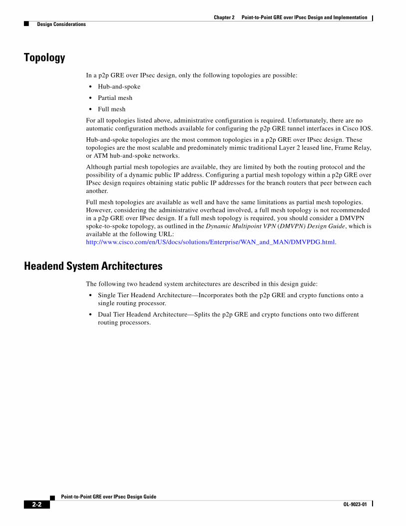
Figure 2-1 shows a Single Tier Headend Architecture for the p2p GRE over IPsec design.
Figure 2-1 p2p GRE over IPsec—Single Tier Headend Architecture
The Single Tier Headend Architecture incorporates all three of the control planes shown in Figure 2-1 into a single routing processor. This architecture impacts scalability, where the central CPU becomes the gating factor.
Headend Site 1
Branch Offices
148878
IP
Headend Site 2
Home Offices
Broadband,Frac-T1, T1
WAN Edge DS3,OC3, OC12
Broadband
Primary p2p GRE over IPsec TunnelSecondary p2p GRE over IPsec Tunnel
Routing ControlPlane
DynamicRouting
IPsec ControlPlane
Dynamic or StaticCrypto Map
DPD Static Crypto Mapor Tunnel Protection
DPD
Headend Branch
DynamicRouting
GRE ControlPlane
Point-to-PointGRE
Point-to-PointGRE
2-3Point-to-Point GRE over IPsec Design Guide
OL-9023-01
Chapter 2 Point-to-Point GRE over IPsec Design and Implementation Design Considerations
Dual Tier Headend Architecture
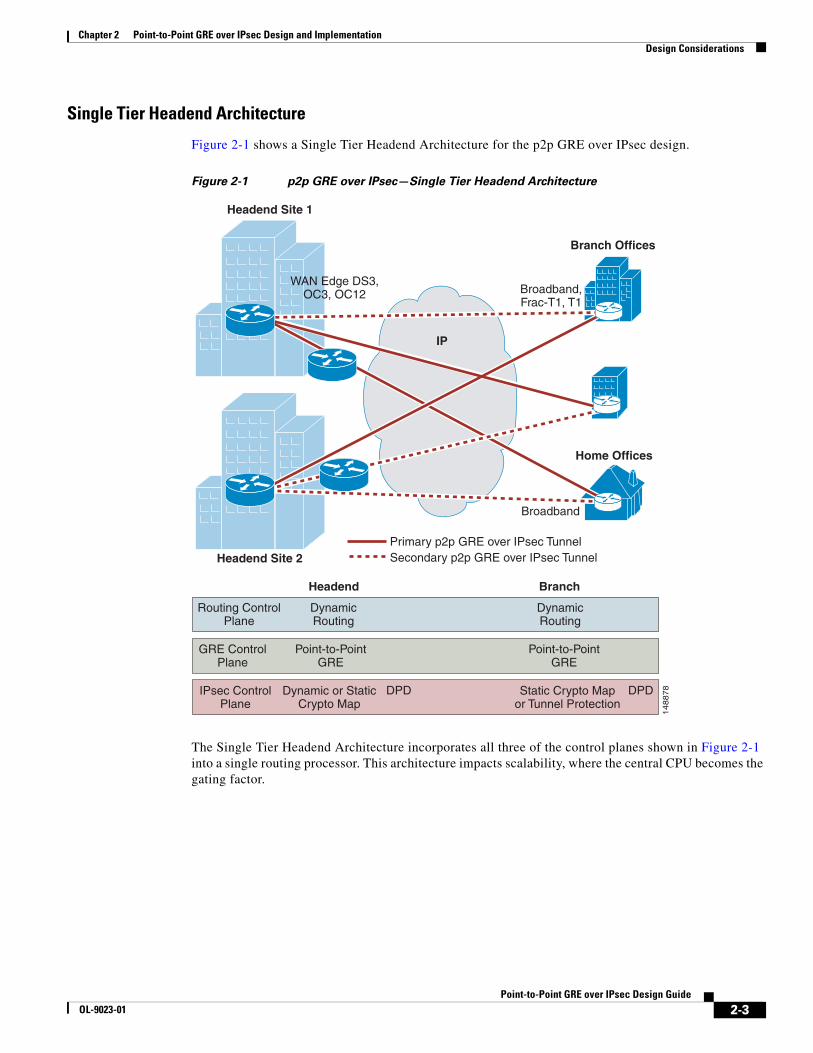
Figure 2-2 shows a Dual Tier Headend Architecture for the p2p GRE over IPsec design.
Figure 2-2 p2p GRE over IPsec—Dual Tier Headend Architecture
The Dual Tier Headend Architecture incorporates the three control planes shown in Figure 2-2 into two routing processors. Both the routing and GRE control planes are housed on one routing process, while the IPsec control plane is housed on another. The reason for separating the functionality is to provide the best scalable solution given various platform limitations; specifically, CPU dependencies and resiliency.
Headend Site 1
Branch Offices
148879
IPWAN
Headend Site 2
Home Offices
Broadband,Frac-T1, T1
WAN Edge DS3,OC3, OC12
Broadband
Primary p2p GRE over IPsec TunnelSecondary p2p GRE over IPsec Tunnel
Routing ControlPlane
DynamicRouting
IPsec ControlPlane
Dynamic Crypto Map
DPD Static CryptoMap
DPD
Headend Branch
DynamicRouting
GRE ControlPlane
Point-to-PointGRE
Point-to-PointGRE
2-4Point-to-Point GRE over IPsec Design Guide
OL-9023-01
Chapter 2 Point-to-Point GRE over IPsec Design and Implementation Design Considerations
IP AddressingProper address summarization is highly recommended because it accomplishes the following:
• Conserves router resources, making routing table sizes smaller
• Saves memory in routers
• Eases troubleshooting tasks
• Simplifies the configuration of routers in IPsec networks
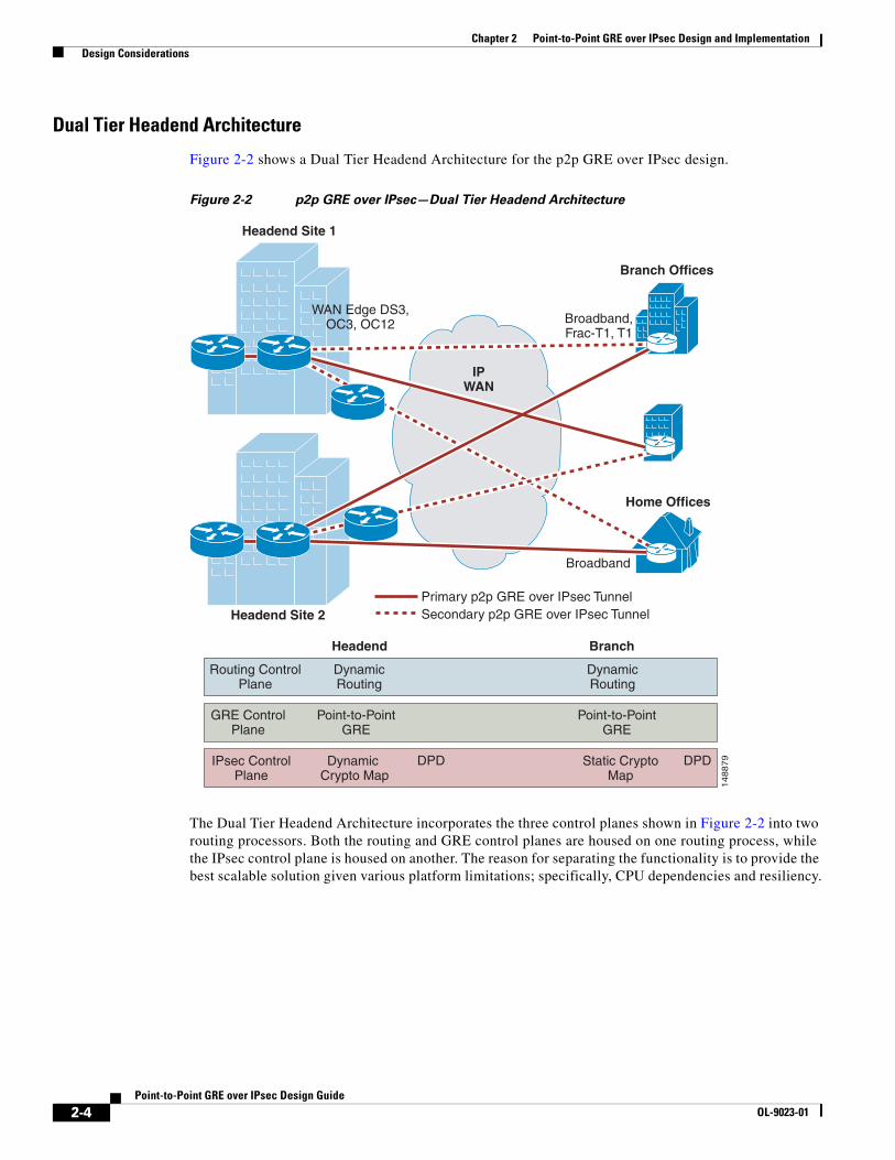
Although it is generally understood that VPNs are used for secure communications across a shared infrastructure (such as the Internet), make sure to distinguish between the enterprise addressing space, sometimes referred to as the private or inside addresses; and the infrastructure addressing space, also referred to as the service provider, public, or outside addresses. (See Figure 2-3.)
Figure 2-3 Private and Public Address Spaces
In most p2p GRE over IPsec VPN designs, the outside interface of the router is addressed in the infrastructure (or public) address space assigned by the service provider, while the tunnel interface belongs to the enterprise private network address space. In a static p2p GRE over a static IPsec configuration, the tunnel interfaces are sourced and destined to the public addresses. However, in the dynamic crypto peer address and static p2p GRE configuration, the branch router crypto IP address is dynamically obtained. For configuration details, see Static p2p GRE over IPsec with a Branch Dynamic Public IP Address Case Study, page 5-1.
Tunnel Interface
PrivateAddressSpace
PublicAddressSpace
PrivateAddressSpace
Outside Interface
Outside Interface
Tunnel Interface
1261
30
2-5Point-to-Point GRE over IPsec Design Guide
OL-9023-01
Chapter 2 Point-to-Point GRE over IPsec Design and Implementation Design Considerations
Generic Route EncapsulationAlthough IPsec provides a secure method for tunneling data across an IP network, it has limitations. IPsec does not support IP broadcast or IP multicast, preventing the use of protocols that rely on these features, such as routing protocols. IPsec also does not support the use of multiprotocol traffic.
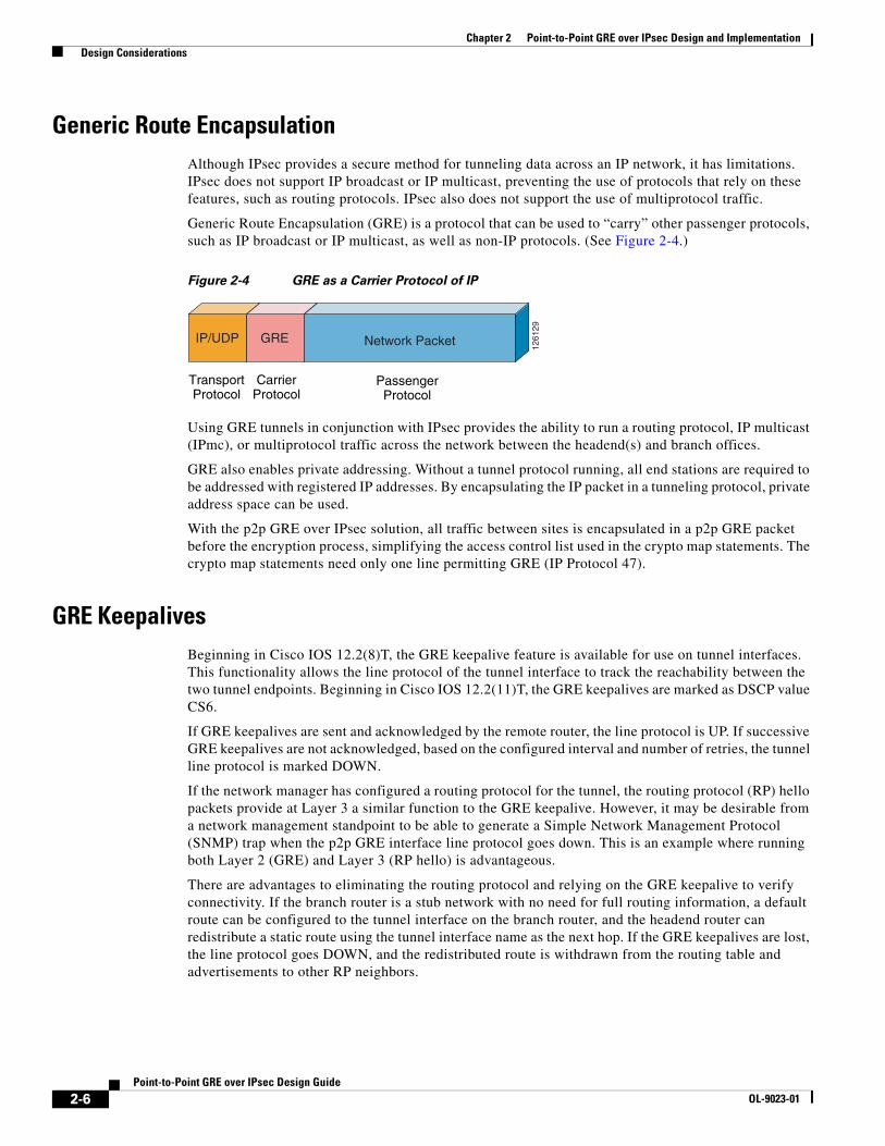
Generic Route Encapsulation (GRE) is a protocol that can be used to “carry” other passenger protocols, such as IP broadcast or IP multicast, as well as non-IP protocols. (See Figure 2-4.)
Figure 2-4 GRE as a Carrier Protocol of IP
Using GRE tunnels in conjunction with IPsec provides the ability to run a routing protocol, IP multicast (IPmc), or multiprotocol traffic across the network between the headend(s) and branch offices.
GRE also enables private addressing. Without a tunnel protocol running, all end stations are required to be addressed with registered IP addresses. By encapsulating the IP packet in a tunneling protocol, private address space can be used.
With the p2p GRE over IPsec solution, all traffic between sites is encapsulated in a p2p GRE packet before the encryption process, simplifying the access control list used in the crypto map statements. The crypto map statements need only one line permitting GRE (IP Protocol 47).
GRE KeepalivesBeginning in Cisco IOS 12.2(8)T, the GRE keepalive feature is available for use on tunnel interfaces. This functionality allows the line protocol of the tunnel interface to track the reachability between the two tunnel endpoints. Beginning in Cisco IOS 12.2(11)T, the GRE keepalives are marked as DSCP value CS6.
If GRE keepalives are sent and acknowledged by the remote router, the line protocol is UP. If successive GRE keepalives are not acknowledged, based on the configured interval and number of retries, the tunnel line protocol is marked DOWN.
If the network manager has configured a routing protocol for the tunnel, the routing protocol (RP) hello packets provide at Layer 3 a similar function to the GRE keepalive. However, it may be desirable from a network management standpoint to be able to generate a Simple Network Management Protocol (SNMP) trap when the p2p GRE interface line protocol goes down. This is an example where running both Layer 2 (GRE) and Layer 3 (RP hello) is advantageous.
There are advantages to eliminating the routing protocol and relying on the GRE keepalive to verify connectivity. If the branch router is a stub network with no need for full routing information, a default route can be configured to the tunnel interface on the branch router, and the headend router can redistribute a static route using the tunnel interface name as the next hop. If the GRE keepalives are lost, the line protocol goes DOWN, and the redistributed route is withdrawn from the routing table and advertisements to other RP neighbors.
CarrierProtocol
GRE
TransportProtocol
IP/UDP
PassengerProtocol
Network Packet
1261
29
2-6Point-to-Point GRE over IPsec Design Guide
OL-9023-01
Chapter 2 Point-to-Point GRE over IPsec Design and Implementation Design Considerations
This reduces the number of RP peers the headend router must maintain, and the branch router configuration is simplified because no RP must be configured. Network stability and performance may be enhanced by reducing the CPU required for the overhead function of maintaining RP neighbors, and instead using those CPU cycles for packet switching.
Using a Routing Protocol across the VPNThis design recommends the use of a routing protocol to propagate routes from the headend to the branch offices. Using a routing protocol has several advantages over the current mechanisms in IPsec Direct Encapsulation alone.
In a VPN, routing protocols provide the same level of benefits as compared to a traditional network, including the following:
• Network topology information
• Topology change notification (such as when a link fails)
• Remote peer status
Several routing protocols are candidates for operation over a p2p GRE over IPsec VPN, including EIGRP and OSPF. Designs presented in this design guide use EIGRP as the routing protocol because EIGRP was used during the scalability tests conducted. EIGRP is recommended as the routing protocol because of its conservative use of router CPU and network bandwidth as well as its quick convergence times. EIGRP also provides a range of options for address summarization and default route propagation.
Other routing protocols, such as OSPF, have been verified in designs, but are not discussed in this design guide.
Routing protocols do increase the CPU utilization on a network device, and this impact must be considered when sizing those devices.
Route Propagation StrategyThere are a number of approaches to propagating routes from the headend to the branch offices. For this design, the recommended approach is for each headend router to advertise either a default route or summary routes down each of the tunnels, with a preferred routing metric for the primary path. With this in mind, each of the branch office routers need to add a static host route for each of the headend peer (primary and secondary) IP addresses, with a next hop destined for their respective ISP IP address. The purpose for the static host routes is to avoid recursive routing through the p2p GRE tunnel. Recursive routing occurs when a route to the p2p GRE tunnel source outside IP address of the opposing router is learned via a route with a next hop of the inside IP address of the opposing p2p GRE tunnel. This breaks the tunnel because it causes the p2p GRE encapsulated packet to be routed into its own p2p GRE tunnel instead of being routed directly.
Crypto ConsiderationsThe use of crypto is imperative to the p2p GRE over IPsec design because it provides the secure channel between the headend and branch routers. The p2p GRE tunnel is encrypted inside the crypto tunnel. For specific crypto considerations, see the IPsec Direct Encapsulation Design Guide at the following URL: http://www.cisco.com/en/US/docs/solutions/Enterprise/WAN_and_MAN/Dir_Encap.html.
2-7Point-to-Point GRE over IPsec Design Guide
OL-9023-01
Chapter 2 Point-to-Point GRE over IPsec Design and Implementation Configuration and Implementation
IPsec Tunnel versus Transport Mode
Integrating p2p GRE with either IPsec tunnel mode or transport mode has been debated. Tunnel mode adds an additional 20 bytes to the total packet size. Either tunnel or transport mode work in a p2p GRE over IPsec implementation; however, several restrictions with transport mode should be considered. If the crypto tunnel transits either a Network Address Translation (NAT) or Port Address Translation (PAT) device, tunnel mode is required. In addition, this design guide shows configuration examples for implementing p2p GRE over IPsec where the p2p GRE tunnel endpoints are different than the crypto tunnel endpoints. Tunnel mode is also required in these cases.
Dead Peer Detection
Dead Peer Detection (DPD) is a relatively new Cisco IOS feature that is actually an enhancement of the ISAKMP keepalives feature. DPD operates by sending a hello message to a crypto peer from which it has not received traffic during a specified configurable period. If normal IPsec traffic is received from a crypto peer and decrypted correctly, that crypto peer is assumed alive, no hello message is sent, and the DPD counter for that crypto peer is reset. This results in lower CPU utilization than that which would have occurred with ISAKMP keepalives.
In the event that no traffic is received during the specified period, an ISAKMP R_U_THERE message is sent to the other crypto peer. If no response is received after the specified number of tries, the connection is assumed dead, and the IPsec tunnel is disconnected. This feature is vital to prevent black-holing traffic, in the event that the Security Association (SA) database of one side is cleared manually or by reboot. DPD is both a headend and branch technology and should be configured on both sides of a VPN tunnel.
DPD should always be configured, even when GRE keepalives or a routing protocol are used.
Configuration and ImplementationThe configuration issues defined in this chapter are specific to VPN implementation for the p2p GRE over IPsec design topology. It is presumed that the reader is reasonably familiar with standard Cisco configuration practices at the command-line interface (CLI) level.
All configuration examples shown are for IPsec in tunnel mode. Also, all references to private or public IP addresses correlate to IP Addressing, page 2-5.
For more details and a step-by-step instruction, see the following URL: http://www.cisco.com/en/US/tech/tk583/tk372/tsd_technology_support_protocol_home.html
ISAKMP Policy ConfigurationThere must be at least one matching ISAKMP policy between two potential crypto peers. The sample configuration below shows a policy using Pre-Shared Keys (PSK) with 3DES as the encryption algorithm. There is a default ISAKMP policy that contains the default values for the encryption algorithm, hash method or Hashed Method Authentication Code (HMAC), Diffie-Hellman group, authentication type, and ISAKMP SA lifetime parameters. This is the lowest priority ISAKMP policy.
2-8Point-to-Point GRE over IPsec Design Guide
OL-9023-01
Chapter 2 Point-to-Point GRE over IPsec Design and Implementation Configuration and Implementation
When using PSK, Cisco recommends that wildcard keys not be used. However, when implementing a p2p GRE over IPsec design using an IP address obtained dynamically, the use of a wildcard PSK or Public Key Infrastructure (PKI) on the headend router is required. Instead, the example shows two keys configured for two separate crypto peers. The keys should be carefully chosen; “bigsecret” is used only as an example. The use of alphanumeric and punctuation characters as keys is recommended.
The following configuration example shows a static public IP address on the branch router with a static public IP address on the headend router for the crypto peer for either a Single or Dual Tier Headend Architecture:
Headend router:
interface FastEthernet1/0ip address 192.168.251.1 255.255.255.0!crypto isakmp policy 10 encr 3des authentication pre-sharecrypto isakmp key bigsecret address 192.168.161.2
Branch router:
interface Serial0/0ip address 192.168.161.2 255.255.255.0!crypto isakmp policy 10 encr 3des authentication pre-sharecrypto isakmp key bigsecret address 192.168.251.1
Note the following:
• In a Single Tier Headend Architecture, the configuration above is applied to the headend router.
• In a Dual Tier Headend Architecture, the configuration above is applied to the crypto headend router.
• In either headend architecture implementing a static p2p GRE over IPsec with a branch dynamic public IP address, a wildcard PSK or PKI must be used on the crypto headend router.
For more information regarding configuring ISAKMP policies, see the following URL: http://www.cisco.com/en/US/docs/ios/12_2/security/command/reference/srfike.html.
Dead Peer Detection ConfigurationAn enhancement to the crypto isakmp keepalive command has changed the way that ISAKMP keepalives work, creating the feature known as Dead Peer Detection (DPD). DPD no longer automatically sends hello messages to the ISAKMP peer if live traffic has been received from that peer within a specified period. The first variable in the crypto isakmp keepalive command is the number of seconds that the peer waits for valid traffic from its crypto neighbor. If no traffic has been received, the second variable is the number of seconds between retries. This scheme helps conserve router CPU by not sending the keepalive messages if a router has just received valid traffic.
The following configuration example shows a static public IP address on the branch router with a static public IP address on the headend router for the crypto peer for either a Single or Dual Tier Headend Architecture:
Headend router:
interface FastEthernet1/0ip address 192.168.251.1 255.255.255.0
2-9Point-to-Point GRE over IPsec Design Guide
OL-9023-01
Chapter 2 Point-to-Point GRE over IPsec Design and Implementation Configuration and Implementation
!crypto isakmp policy 10 encr 3des authentication pre-sharecrypto isakmp key bigsecret address 192.168.161.2crypto isakmp keepalive 10!
Branch router:
interface Serial0/0ip address 192.168.161.2 255.255.255.0!crypto isakmp policy 10 encr 3des authentication pre-sharecrypto isakmp key bigsecret address 192.168.251.1crypto isakmp keepalive 10!
Note the following:
• In a Single Tier Headend Architecture, the configuration above is applied to the headend router.
• In a Dual Tier Headend Architecture, the configuration above is applied to the crypto headend router.
• In either headend architecture implementing a static p2p GRE over IPsec with a branch dynamic public IP address, a wildcard PSK or PKI must be used on the crypto headend router.
IPsec Transform and Protocol ConfigurationThe transform set must match between the two IPsec peers. The transform set names are locally significant only. However, the encryption algorithm, hash method, and the particular protocols used (ESP or AH) must match. You may also configure data compression here but it is not recommended on peers with high speed links. There can be multiple transform sets for use between different peers, with the strongest match being negotiated.
The following configuration example shows a static public IP address on the branch router with a static public IP address on the headend router for the crypto peer for either a Single or Dual Tier Headend Architecture:
Headend router:
interface FastEthernet1/0ip address 192.168.251.1 255.255.255.0!crypto isakmp policy 10 encr 3des authentication pre-sharecrypto isakmp key bigsecret address 192.168.161.2crypto isakmp keepalive 10!!crypto ipsec transform-set vpn-test esp-3des esp-sha-hmac
Branch router:
interface Serial0/0ip address 192.168.161.2 255.255.255.0!crypto isakmp policy 10
2-10Point-to-Point GRE over IPsec Design Guide
OL-9023-01
Chapter 2 Point-to-Point GRE over IPsec Design and Implementation Configuration and Implementation
encr 3des authentication pre-sharecrypto isakmp key bigsecret address 192.168.251.1crypto isakmp keepalive 10!!crypto ipsec transform-set vpn-test esp-3des esp-sha-hmac
Note the following:
• In a Single Tier Headend Architecture, the configuration above is applied to the headend router.
• In a Dual Tier Headend Architecture, the configuration above is applied to the crypto headend router.
• In either headend architecture implementing a static p2p GRE over IPsec with a branch dynamic public IP address, a wildcard PSK or PKI must be used on the crypto headend router.
For more information on transform sets and configuring crypto maps, see the following URL: http://www.cisco.com/en/US/docs/ios/12_2/security/command/reference/srfipsec.html.
Access Control List Configuration for EncryptionThe access control list entries defining the traffic to be encrypted should be mirror images of each other on the crypto peers. If access control list entries include ranges of ports, a mirror image of those same ranges must be included on the access control lists of the remote peer. The addresses specified in these access control lists are independent of the addresses used by the crypto peers. This example specifies the IP protocol GRE on both the source and destination parts of the access control list. All traffic encapsulated in the p2p GRE packets is protected.
The following configuration example shows a static public IP address on the branch router with a static public IP address on the headend router for the crypto peer for either a Single or Dual Tier Headend Architecture:
Headend router:
ip access-list extended vpn-static1 permit gre host 192.168.251.1 host 192.168.1.2
Branch router:
ip access-list extended vpn-static2 permit gre host 192.168.1.2 host 192.168.251.1
Note the following:
• In a Single Tier Headend Architecture, the configuration above is applied to the headend router.
• In a Dual Tier Headend Architecture, the configuration above is applied to the crypto headend router. However, note that the p2p GRE headend source and destination public IP addresses are different from the crypto headend. The crypto ACL needs to match the p2p GRE tunnel endpoints.
• In either headend architecture implementing a static p2p GRE over IPsec with a branch dynamic public IP address, the headend crypto ACL is not required. The headend router uses a dynamic crypto map that dynamically creates its crypto ACL from the incoming branch router crypto ACL. The branch router ACL is identical to the configuration example above.
Crypto Map ConfigurationThe crypto map entry ties together the crypto peers, the transform set used, and the access control list used to define the traffic to be encrypted. The crypto map entries are evaluated sequentially.
2-11Point-to-Point GRE over IPsec Design Guide
OL-9023-01
Chapter 2 Point-to-Point GRE over IPsec Design and Implementation Configuration and Implementation
In the example below, the crypto map name “static-map” and crypto map numbers (for example, “10” and “20”) are locally significant only. The first statement sets the IP address used by this peer to identify itself to other crypto peers in this crypto map. This address must match the set peer statement in the crypto map entries of the remote crypto peers. This address also needs to match the address used with any PSK the remote peers might have configured. The IPsec mode defaults to tunnel mode.
The following configuration example shows a static public IP address on the branch router with a static public IP address on the headend router for the crypto peer for either a Single or Dual Tier Headend Architecture:
Headend router:
interface FastEthernet1/0ip address 192.168.251.1 255.255.255.0!crypto map static-map local-address FastEthernet1/0crypto map static-map 10 ipsec-isakmp set peer 192.168.161.2 set transform-set vpn-test match address vpn-static1
Branch router:
interface Serial0/0ip address 192.168.161.2 255.255.255.0!crypto map static-map local-address Serial0/0crypto map static-map 20 ipsec-isakmp set peer 192.168.251.1 set transform-set vpn-test match address vpn-static2
Note the following:
• In a Single Tier Headend Architecture, the configuration above is applied to the headend router
• In a Dual Tier Headend Architecture, the configuration above is applied to the crypto headend router
The following configuration example shows a dynamic public IP address on the branch router with a static public IP address on the headend router for the crypto peers for either a Single or Dual Tier Headend Architecture:
Headend router:
interface FastEthernet1/0ip address 192.168.251.1 255.255.255.0!crypto isakmp key bigsecret address 0.0.0.0 0.0.0.0!crypto dynamic-map dmap 10 set transform-set vpn-test!!crypto map dynamic-map local-address FastEthernet1/0crypto map dynamic-map 10 ipsec-isakmp dynamic dmap
Branch router:
interface Serial0/0ip address dhcp!crypto isakmp key bigsecret address 192.168.251.1!crypto map static-map local-address Serial0/0crypto map static-map 20 ipsec-isakmp
2-12Point-to-Point GRE over IPsec Design Guide
OL-9023-01
Chapter 2 Point-to-Point GRE over IPsec Design and Implementation Configuration and Implementation
set peer 192.168.251.1 set transform-set vpn-test match address vpn-static2
On the headend router, a dynamic crypto map is used with a wildcard PSK to allow a crypto peer with the public dynamically served IP address of the branch router.
Note the following:
• In a Single Tier Headend Architecture, the configuration above is applied to the headend router.
• In a Dual Tier Headend Architecture, the configuration above is applied to the crypto headend router.
For a more complete description of the various crypto configuration commands, see the following URL: http://www.cisco.com/en/US/docs/ios/12_2/security/command/reference/srfipsec.html.
Applying Crypto MapsIn releases before Cisco IOS Release 12.2(13)T, the crypto maps must be applied to both the physical interface and the logical interfaces, such as the p2p GRE tunnel interfaces. As of Cisco IOS Release 12.2(13)T (assumed in the example below), the crypto map is applied only to the physical interface, not to the logical interface.
The following configuration example shows a static public IP address on the branch router with a static public IP address on the headend router for the crypto peer for either a Single or Dual Tier Headend Architecture:
Headend router:
interface FastEthernet1/0ip address 192.168.251.1 255.255.255.0crypto map static-map
Branch router
interface Serial0/0 ip address 192.168.161.2 255.255.255.0 crypto map static-map
Note the following:
• In a Single Tier Headend Architecture, the configuration above is applied to the headend router.
• Ιn a Dual Tier Headend Architecture, the configuration above is applied to the crypto headend router.
The following configuration example shows a public dynamic IP address on the branch router with a static public IP address on the headend router for the crypto peers for either a Single or Dual Tier Headend Architecture:
Headend router:
interface FastEthernet1/0ip address 192.168.251.1 255.255.255.0crypto map dynamic-map
Branch router:
interface Serial0/0 ip address dhcp crypto map static-map
Note the following:
2-13Point-to-Point GRE over IPsec Design Guide
OL-9023-01
Chapter 2 Point-to-Point GRE over IPsec Design and Implementation Configuration and Implementation
• In a Single Tier Headend Architecture, the configuration above is applied to the headend router.
• In a Dual Tier Headend Architecture, the configuration above is applied to the crypto headend router.
Tunnel Interface Configuration—Branch Static Public IP AddressThis section shows the tunnel interface configurations using a branch static public IP address.
The following configuration example shows a static public IP address on the branch router with a static public IP address on the headend router for the p2p GRE tunnel for either a Single or Dual Tier Headend Architecture:
Headend router:
interface Tunnel0 bandwidth 1536 ip address 10.62.1.193 255.255.255.252 tunnel source 192.168.251.1 tunnel destination 192.168.161.2
Branch router:
interface Tunnel0 bandwidth 1536 ip address 10.62.1.194 255.255.255.252 tunnel source 192.168.161.2 tunnel destination 192.168.251.1
Note the following:
• In a Single Tier Headend Architecture, the configuration above is applied to the headend router.
• In a Dual Tier Headend Architecture, the configuration above is applied to the p2p GRE headend router. The p2p GRE headend router has a different static public IP address than the crypto headend router.
Tunnel Interface Configuration—Branch Dynamic Public IP Address This section shows the tunnel interface configurations using a branch dynamic public IP address.
The following configuration example shows a dynamic public IP address on the branch router with a static public IP address on the headend router for the p2p GRE tunnel for either a Single or Dual Tier Headend Architecture:
Headend router:
interface FastEthernet1/0 ip address 192.168.251.1 255.255.255.0!interface Tunnel0 bandwidth 1536 ip address 10.62.1.193 255.255.255.252 tunnel source 192.168.251.1 tunnel destination 10.62.1.255!ip route 10.62.1.255 255.255.255 192.168.251.2
Branch router:
2-14Point-to-Point GRE over IPsec Design Guide
OL-9023-01
Chapter 2 Point-to-Point GRE over IPsec Design and Implementation Configuration and Implementation
interface Serial0/0 ip address dhcp!interface Loopback0 ip address 10.62.1.255 255.255.255.255!interface Tunnel0 bandwidth 1536 ip address 10.62.1.194 255.255.255.252 tunnel source 10.62.1.255 tunnel destination 192.168.251.1
Note the following:
• In a Single Tier Headend Architecture, the configuration above is applied to the headend router.
• In a Dual Tier Headend Architecture, the configuration above is applied to the p2p GRE headend router. The p2p GRE headend router has a different static public IP address than the crypto headend router. The static host route of the p2p GRE headend router to the Loopback0 IP address of the branch router may not be required because the p2p GRE headend router sends all traffic to the crypto headend router.
For more detailed information, see Static p2p GRE over IPsec with a Branch Dynamic Public IP Address Case Study, page 5-1.
GRE Keepalive ConfigurationThis section shows a sample headend and branch configuration using GRE keepalives.
The following configuration example shows a static public IP address on the branch router with a static public IP address on the headend router for the p2p GRE tunnel for either a Single or Dual Tier Headend Architecture:
Headend router:
interface Tunnel0 ip address 10.62.1.193 255.255.255.252 keepalive 10 3!ip route 10.62.1.0 255.255.255.0 10.62.1.194
Branch router:
interface Tunnel0 ip address 10.62.1.194 255.255.255.252 keepalive 10 3!ip route 10.0.0.0 255.0.0.0 10.62.1.193
Note the following:
• In a Single Tier Headend Architecture, the configuration above is applied to the headend router.
• In a Dual Tier Headend Architecture, the configuration above is applied to the p2p GRE headend router. The p2p GRE headend router has a different static public IP address than the crypto headend router.
• In either headend architecture implementing a static p2p GRE over IPsec with a branch dynamic public IP address, the configuration above is the same.
2-15Point-to-Point GRE over IPsec Design Guide
OL-9023-01
Chapter 2 Point-to-Point GRE over IPsec Design and Implementation Configuration and Implementation
GRE keepalives are a trigger mechanism to cause the line protocol to be changed from an UP/UP to an UP/DOWN state during a failure event. A floating static route can be used in place of a routing protocol on the branch router. In the headend router, a routing protocol may be required to redistribute the static routes into the campus network topology.
Routing Protocol ConfigurationThis section shows a sample headend and branch configuration using EIGRP as the routing protocol.
The following configuration example shows a static public IP address on the branch router with a static public IP address on the headend router for the p2p GRE tunnel for either a Single or Dual Tier Headend Architecture:
Headend router:
interface FastEthernet0/0 ip address 10.57.1.1 255.255.255.0!interface Tunnel0 ip address 10.62.1.193 255.255.255.252!router eigrp 10 network 10.0.0.0 no auto-summary
Branch router:
interface FastEthernet0/0 ip address 10.62.1.1 255.255.255.128!interface Tunnel0 ip address 10.62.1.194 255.255.255.252!router eigrp 10 network 10.0.0.0 no auto-summary
Note the following:
• In a Single Tier Headend Architecture, the configuration above is applied to the headend router.
• In a Dual Tier Headend Architecture, the configuration above is applied to the p2p GRE headend router.
• In either headend architecture implementing a static p2p GRE over IPsec with a branch dynamic public IP address, the configuration above is the same.
2-16Point-to-Point GRE over IPsec Design Guide
OL-9023-01
Chapter 2 Point-to-Point GRE over IPsec Design and Implementation High Availability
Route Propagation ConfigurationThis section shows a sample headend and branch configuration using EIGRP as the routing protocol redistributing a static route into the EIGRP routing process.
The following configuration example shows a static public IP address on the branch router with a static public IP address on the headend router for the p2p GRE tunnel for either a Single or Dual Tier Headend Architecture:
Headend router:
interface FastEthernet1/0 ip address 192.168.251.1 255.255.255.0!router eigrp 10 network 10.0.0.0 no auto-summary redistribute static metric metric 10000 10 255 1 1500!ip route 0.0.0.0 0.0.0.0 192.168.251.2
Branch router:
interface Serial0/0 ip address dhcp!router eigrp 10 network 10.0.0.0 no auto-summary!ip route 192.168.251.1 255.255.255.255 dhcp
Note the following:
• In a Single Tier Headend Architecture, the configuration above is applied to the headend router.
• In a Dual Tier Headend Architecture, the configuration above is applied to the p2p GRE headend router.
• In either headend architecture implementing a static p2p GRE over IPsec with a branch dynamic public IP address, the configuration above is the same.
In the above example, a default route is being redistributed into EIGRP AS 10 on the headend router and then advertised to the branch router with an administrative distance (AD) of 90. Considering that the branch router has a default route learned via DHCP with an AD of 254, recursive routing must be taken into account. To avoid recursive routing on the branch router, a static host route for the crypto peer address is added to the configuration to ensure that the outside of the tunnel is routed directly to the ISP instead of inside the p2p GRE tunnel.
High AvailabilityHigh Availability (HA) provides network resilience and availability in the event of a failure. This section provides some designs for highly available p2p GRE over IPsec VPNs. HA is covered in much more depth in the V3PN: Redundancy and Load Sharing Design Guide at the following URL: http://www.cisco.com/en/US/docs/solutions/Enterprise/WAN_and_MAN/VPNLoad/VPN_Load.html.
2-17Point-to-Point GRE over IPsec Design Guide
OL-9023-01
Chapter 2 Point-to-Point GRE over IPsec Design and Implementation High Availability
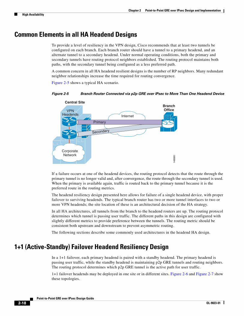
Common Elements in all HA Headend DesignsTo provide a level of resiliency in the VPN design, Cisco recommends that at least two tunnels be configured on each branch. Each branch router should have a tunnel to a primary headend, and an alternate tunnel to a secondary headend. Under normal operating conditions, both the primary and secondary tunnels have routing protocol neighbors established. The routing protocol maintains both paths, with the secondary tunnel being configured as a less preferred path.
A common concern in all HA headend resilient designs is the number of RP neighbors. Many redundant neighbor relationships increase the time required for routing convergence.
Figure 2-5 shows a typical HA scenario.
Figure 2-5 Branch Router Connected via p2p GRE over IPsec to More Than One Headend Device
If a failure occurs at one of the headend devices, the routing protocol detects that the route through the primary tunnel is no longer valid and, after convergence, the route through the secondary tunnel is used. When the primary is available again, traffic is routed back to the primary tunnel because it is the preferred route in the routing metrics.
The headend resiliency design presented here allows for failure of a single headend device, with proper failover to surviving headends. The typical branch router has two or more tunnel interfaces to two or more VPN headends; the site location of these is an architectural decision of the HA strategy.
In all HA architectures, all tunnels from the branch to the headend routers are up. The routing protocol determines which tunnel is passing user traffic. The different paths in this design are configured with slightly different metrics to provide preference between the tunnels. The routing metric should be consistent both upstream and downstream to prevent asymmetric routing.
The following sections describe some commonly used architectures in the headend HA design.
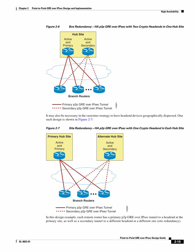
1+1 (Active-Standby) Failover Headend Resiliency DesignIn a 1+1 failover, each primary headend is paired with a standby headend. The primary headend is passing user traffic, while the standby headend is maintaining p2p GRE tunnels and routing neighbors. The routing protocol determines which p2p GRE tunnel is the active path for user traffic.
1+1 failover headends may be deployed in one site or in different sites. Figure 2-6 and Figure 2-7 show these topologies.
CorporateNetwork
Central Site
1488
80
Internet
BranchOffice
Secondary
Primary
VPNHeadends
A
B
2-18Point-to-Point GRE over IPsec Design Guide
OL-9023-01
Chapter 2 Point-to-Point GRE over IPsec Design and Implementation High Availability
Figure 2-6 Box Redundancy—HA p2p GRE over IPsec with Two Crypto Headends in One Hub Site
It may also be necessary in the customer strategy to have headend devices geographically dispersed. One such design is shown in Figure 2-7:
Figure 2-7 Site Redundancy—HA p2p GRE over IPsec with One Crypto Headend in Each Hub Site
In this design example, each remote router has a primary p2p GRE over IPsec tunnel to a headend at the primary site, as well as a secondary tunnel to a different headend at a different site (site redundancy).
1488
81Primary p2p GRE over IPsec TunnelSecondary p2p GRE over IPsec Tunnel
Branch Routers
Activeand
Primary
Hub Site
Activeand
Secondary
1488
82
Activeand
Primary
Activeand
Secondary
Branch Routers
Primary p2p GRE over IPsec TunnelSecondary p2p GRE over IPsec Tunnel
Primary Hub Site Alternate Hub Site
2-19Point-to-Point GRE over IPsec Design Guide
OL-9023-01
Chapter 2 Point-to-Point GRE over IPsec Design and Implementation High Availability
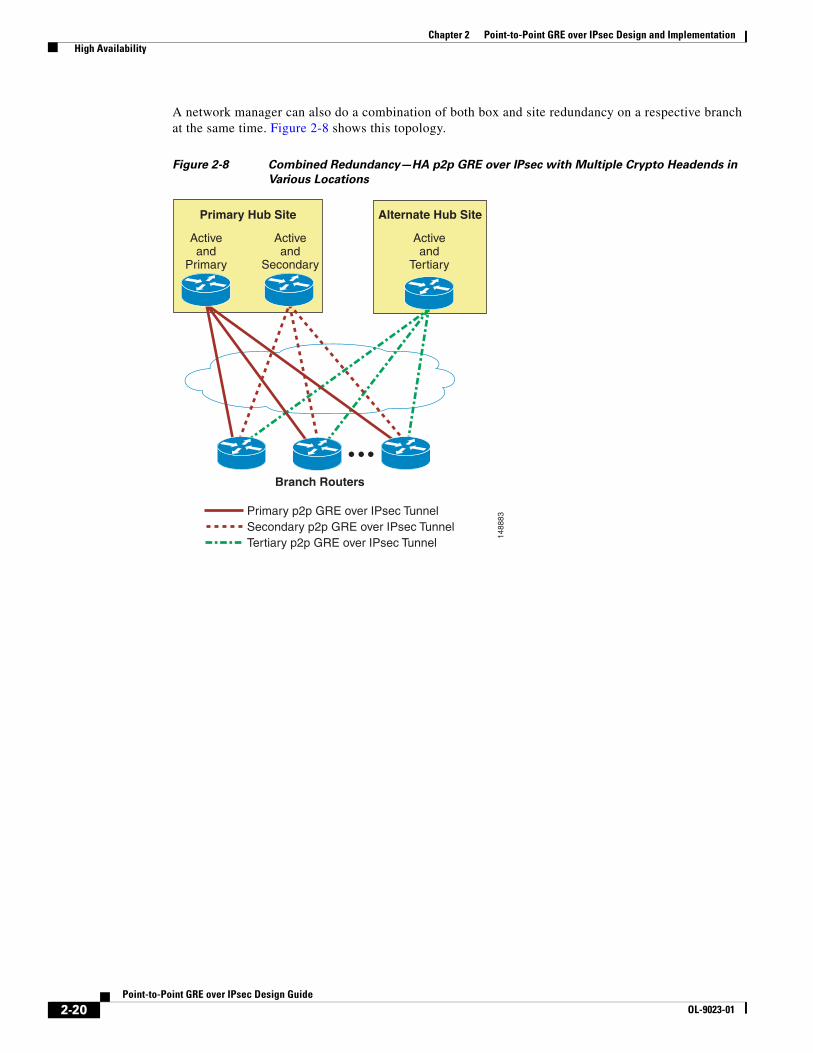
A network manager can also do a combination of both box and site redundancy on a respective branch at the same time. Figure 2-8 shows this topology.
Figure 2-8 Combined Redundancy—HA p2p GRE over IPsec with Multiple Crypto Headends in
Various Locations
1488
83
Activeand
Tertiary
Activeand
Primary
Activeand
Secondary
Branch Routers
Primary p2p GRE over IPsec TunnelSecondary p2p GRE over IPsec TunnelTertiary p2p GRE over IPsec Tunnel
Alternate Hub SitePrimary Hub Site
2-20Point-to-Point GRE over IPsec Design Guide
OL-9023-01
Chapter 2 Point-to-Point GRE over IPsec Design and Implementation High Availability
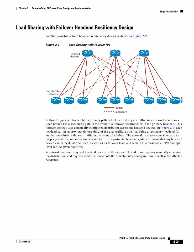
Load Sharing with Failover Headend Resiliency DesignAnother possibility for a headend redundancy design is shown in Figure 2-9.
Figure 2-9 Load Sharing with Failover HA
In this design, each branch has a primary path, which is used to pass traffic under normal conditions. Each branch has a secondary path in the event of a failover occurrence with the primary headend. This failover strategy uses a manually configured distribution across the headend devices. In Figure 2-9, each headend carries approximately one-third of the user traffic, as well as being a secondary headend for another one-third of the user traffic in the event of a failure. The network manager must take care to properly scale the amount of tunnels and traffic to a particular headend system to ensure that any headend device can carry its normal load, as well as its failover load, and remain at a reasonable CPU and pps level for the given platform.
A network manager may add headend devices to this series. This addition requires manually changing the distribution, and requires modification to both the branch router configurations as well as the affected headends.
1321
68
Primary
Secondary
Headenddevices
Branch Officedevices
2-21Point-to-Point GRE over IPsec Design Guide
OL-9023-01
Chapter 2 Point-to-Point GRE over IPsec Design and Implementation High Availability
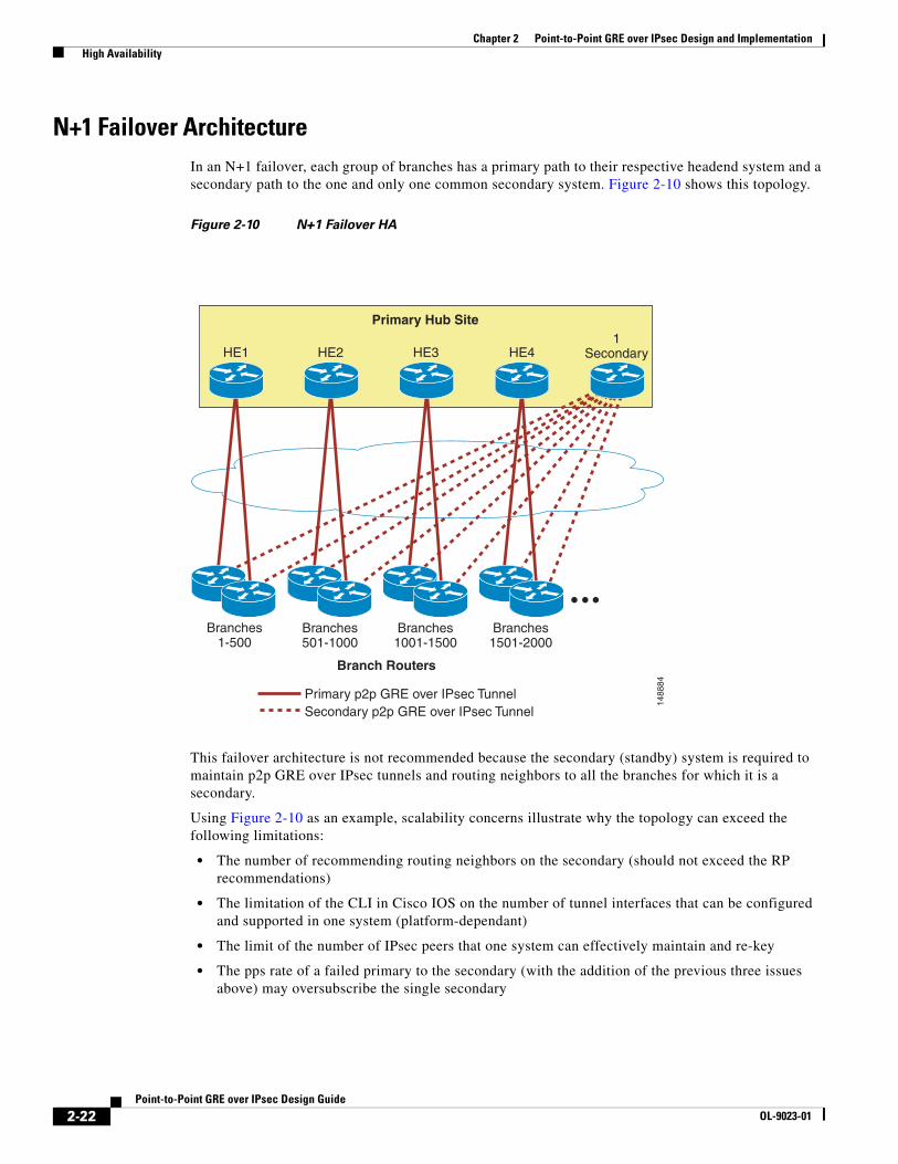
N+1 Failover ArchitectureIn an N+1 failover, each group of branches has a primary path to their respective headend system and a secondary path to the one and only one common secondary system. Figure 2-10 shows this topology.
Figure 2-10 N+1 Failover HA
This failover architecture is not recommended because the secondary (standby) system is required to maintain p2p GRE over IPsec tunnels and routing neighbors to all the branches for which it is a secondary.
Using Figure 2-10 as an example, scalability concerns illustrate why the topology can exceed the following limitations:
• The number of recommending routing neighbors on the secondary (should not exceed the RP recommendations)
• The limitation of the CLI in Cisco IOS on the number of tunnel interfaces that can be configured and supported in one system (platform-dependant)
• The limit of the number of IPsec peers that one system can effectively maintain and re-key
• The pps rate of a failed primary to the secondary (with the addition of the previous three issues above) may oversubscribe the single secondary
1488
84Branch Routers
Primary p2p GRE over IPsec TunnelSecondary p2p GRE over IPsec Tunnel
HE1
Primary Hub Site
HE2 HE3 HE41
Secondary
Branches1-500
Branches501-1000
Branches1001-1500
Branches1501-2000
2-22Point-to-Point GRE over IPsec Design Guide
OL-9023-01
Chapter 2 Point-to-Point GRE over IPsec Design and Implementation QoS
Dual Tier Headend Architecture Effect on FailoverThe architectures shown in the previous sections have been Single Tier Headend Architectures (crypto, GRE, and RP all on one headend system). If a Dual Tier Headend Architecture is implemented, the crypto functionality is separated from the GRE and RP functions. The crypto failover portion now has more failover options (see Section 4.3 of the IPsec Direct Encapsulation Design Guide at the following URL: http://www.cisco.com/en/US/docs/solutions/Enterprise/WAN_and_MAN/Dir_Encap.html).
The following p2p GRE and RP strategies are still valid architectures for the traffic failover:
• 1+1 failover (box, site, or combined)
• Load sharing with failover
QoSTo support latency-sensitive traffic applications, it may be necessary to configure QoS. QoS and IPsec have been integrated as part of the Cisco Voice and Video Enabled IPsec VPN (V3PN) technology.
For more information, see the following documents:
• Voice and Video IPSec VPN (V3PN)Design Guide— http://www.cisco.com/en/US/docs/solutions/Enterprise/WAN_and_MAN/V3PN_SRND/V3PN_SRND.html
• Enterprise QoS Solution Reference Network Design Guide— http://www.cisco.com/en/US/docs/solutions/Enterprise/WAN_and_MAN/QoS_SRND/QoS-SRND-Book.html.
IP Multicast Scalability testing with IP multicast and IPsec encryption indicates that there are issues with packet loss, because of the instant replication of many packets. IP multicast replication happens at a single moment in time. The replication occurs before encryption, meaning that the crypto cards or engines in the various platforms can be overwhelmed if a large number of spokes are joined to the same IP multicast stream.
For example, consider a design using the Cisco Catalyst 6500 with VPN SPA, and configuring 1000 p2p GRE over IPsec tunnels to branch offices. If each branch office is joined to a single IP multicast stream, the VPN SPA must replicate each IP multicast packet 1000 times, one per VPN tunnel. Assuming the Sup720 can sustain the replication speed of the stream, many packets (up to 1000) arrive at the input queue of the VPN SPA, causing overruns or dropped packets.
For appropriate scalable designs if the customer has multicast requirements, see the Multicast over IPsec VPN Design Guide at the following URL: http://www.cisco.com/en/US/docs/solutions/Enterprise/WAN_and_MAN/V3PNIPmc.html.
Interactions with Other Networking FunctionsThis section describes other networking functions such as PAT, DHCP, and firewall considerations that apply to designing a p2p GRE over IPsec design.
2-23Point-to-Point GRE over IPsec Design Guide
OL-9023-01
Chapter 2 Point-to-Point GRE over IPsec Design and Implementation Interactions with Other Networking Functions
Network Address Translation and Port Address TranslationAlthough NAT and PAT can result in an added layer of security and address conservation, they both present challenges to the implementation of an IPsec VPN. ISAKMP relies on an individual IP address per crypto peer for proper operation. PAT works by masquerading multiple crypto peers behind a single IP address.
The IPsec NAT Traversal feature (NAT-T) introduces support for IPsec traffic to travel through NAT or PAT devices by encapsulating both the IPsec SA and the ISAKMP traffic in a UDP wrapper. NAT-T was first introduced in Cisco IOS version 12.2(13)T, and is auto-detected by VPN devices. There are no configurations steps for a Cisco IOS router running this release or later because it is enabled by default as a global command. The NAT-T feature detects a PAT device between the crypto peers and negotiates NAT-T if it is present.
For more details on IPsec NAT-T, see the following URL: http://www.cisco.com/en/US/docs/ios/12_2t/12_2t13/feature/guide/ftipsnat.html.
Dynamic Host Configuration ProtocolFor a host at a remote site to be able to use a DHCP server over an IPsec tunnel at a central site, an IP helper address must be configured on the router interface associated with the host.
One drawback of this approach is that if connectivity to the central site is lost, a host at a remote site may not receive or renew an IP address. The inability to receive an IP address results in the host being unable to communicate to the local network.
A Cisco IOS router can be configured as a DHCP server. Using the router as a stand-alone DHCP server is recommended for branch offices with no redundant links.
Firewall ConsiderationsThis section describes the various firewall considerations when implementing a p2p over GRE design.
Headend or Branch
Depending on the crypto and p2p GRE headend or branch placements, the following protocols and ports are required to be allowed:
• UDP Port 500—ISAKMP as source and destination
• UDP Port 4500—NAT-T as a destination
• IP Protocol 50—ESP
• IP Protocol 51—AH (if AH is implemented)
• IP Protocol 47—GRE (if GRE traverses the firewall post decryption)
• Any potential end user traffic—If GRE does not traverse the firewall post encapsulation
Network location of the crypto headend in relation to the headend firewall(s) impacts both the accessibility and performance of the both systems. The network manager must ensure that all firewalls are properly configured to allow the tunnel traffic bi-directionally. The crypto headend must be accessible to the branch router.
2-24Point-to-Point GRE over IPsec Design Guide
OL-9023-01

Chapter 2 Point-to-Point GRE over IPsec Design and Implementation Interactions with Other Networking Functions
Firewall Feature Set and Inbound ACL
Before Cisco IOS version 12.3(8)T, packets received on an interface with an inbound ACL and a crypto map were checked by the inbound ACL twice, before decryption, and as clear-text following decryption. The Crypto Access Check on Clear-Text Packets feature removes the checking of clear-text packets that go through the IPsec tunnel just before or just after decryption.
Double ACL Check Behavior (Before 12.3(8)T)
If the enterprise security policy does not permit split tunnel, and the branch requires Internet access through the IPsec tunnel, the remote routers must also be configured to permit specified TCP and UDP traffic through the inbound access control list when the connection is initiated from within the remote router subnet.
To allow Internet access in non-split tunnel configurations, use Context-Based Access Control (CBAC) in conjunction with the inbound access control list:
ip inspect name CBAC tcpip inspect name CBAC udpip inspect name CBAC ftpip inspect name CBAC sip!interface Ethernet 0description Inside ip address 10.81.7.1 255.255.255.248!interface Ethernet 1 description Outside ip address dhcp ip access-group INPUT_ACL in ip inspect CBAC out!ip access-list extended INPUT_ACL permit udp x.x.x.16 0.0.0.15 any eq isakmp permit udp x.x.x.16 0.0.0.15 any eq non500-isakmp permit esp x.x.x.16 0.0.0.15 any remark ! Enterprise Address space permit ip 10.0.0.0 0.255.255.255 10.81.7.0 0.0.0.7 permit udp any any eq bootpc permit udp x.x.x.40 0.0.0.1 eq ntp any permit tcp x.x.0.0 0.0.15.255 any eq 22 permit icmp any any deny ip any anyend
Crypto Access Check on Clear-Text Packets Feature (12.3(8)T and Later)
The Crypto Access Check on Clear-Text Packets feature removes the checking of inbound, just-decrypted clear-text packets against the outside interface inbound ACL.
When upgrading Cisco IOS to a version that supports this feature, the following statement should be removed from the ip access-list extended INPUT_AC command, and the ip inspect CBAC in command can be removed from interface Ethernet 0:
! Enterprise Address space permit ip 10.0.0.0 0.255.255.255 10.81.7.0 0.0.0.7
2-25Point-to-Point GRE over IPsec Design Guide
OL-9023-01
Chapter 2 Point-to-Point GRE over IPsec Design and Implementation Common Configuration Mistakes
If checking the decrypted clear-text packets against an ACL is desired, that function is now configured inside the crypto map global configuration.
For more information on Crypto Access Check on Clear-Text Packets, see the following URL: http://www.cisco.com/en/US/docs/ios/12_3t/12_3t8/feature/guide/gt_crpks.html.
Common Configuration MistakesThe following sections outline some common mistakes and problems encountered when configuring p2p GRE over IPsec.
Crypto Peer Address Matching using PSKThe IP address used as the crypto source address must match the address configured as the destination address on the crypto peer, and vice-versa. Unless the address is configured specifically, the address of the outgoing interface is used as the crypto peer address, thus causing the crypto peer to die at ISAKMP negotiation.
Transform Set MatchesAt least one matching IPsec transform set must be configured between two crypto peers. When specifying a particular strength of encryption algorithm, a similar strength encryption algorithm should also be configured. Failure to do so can weaken the encryption strength of the entire solution.
ISAKMP Policy MatchingThere is a default ISAKMP policy present in all Cisco IOS devices. This default is encryption DES, HMAC of SHA, IKE authentication of RSA signature, and DH group 1. If a stronger ISAKMP policy is desired, both sides must support that policy.
It is common, but not required, to use the same encryption level transform set and hash methods in ISAKMP policy and IPsec transform set.
2-26Point-to-Point GRE over IPsec Design Guide
OL-9023-01
Related Documents