(de) Bedienungs- anleitung (en) Operating instructions (es) Instrucciones de utilización (fr) Notice d’utilisation (it) Istruzioni d’uso (sv) Bruksanvis- ning 396 468 0005NH Pneumatisches Linearmodul Pneumatic linear module HMPL-...

Welcome message from author
This document is posted to help you gain knowledge. Please leave a comment to let me know what you think about it! Share it to your friends and learn new things together.
Transcript

(de) Bedienungs-anleitung
(en) Operatinginstructions
(es) Instruccionesde utilización
(fr) Noticed’utilisation
(it) Istruzionid’uso
(sv) Bruksanvis-ning
396 4680005NH
Pneumatisches Linearmodul
Pneumatic linear module
HMPL-...

HMPL-...
Festo HMPL-... 0005NH2
Es bedeuten/Symbols/Símbolos/Symboles/Simboli/Teckenförklaring:
Einbau und Inbetriebnahme nur von qualifi-ziertem Fachpersonal, gemäß Bedienungs-anleitung.
WarnungWarning, CautionAtenciónAvertissementAvvertenzaVarning
HinweisPlease notePor favor, observarNoteNotaNotera
UmweltAntipollutionReciclajeRecyclageRiciclaggioÅtervinning
ZubehörAccessoriesAccesoriosAccessoiresAccessoriTillbehör
Fitting and commissioning to be carried outby qualified personnel only in accordancewith the operating instructions.
El montaje y la puesta en funcionamiento,debe ser realizado exclusivamentepor perso-nal cualificado y siguiendo las instruccionesde utilización.
Montage et mise en service uniquement pardu personnel agréé, conformément auxinstructions d’utilisation.
Montaggio e messa in funzione devono es-sere effettuati da personale specializzato edautorizzato in confomità alle istruzioni perl’uso.
Montering och idrifttagning får endast ut-föras av auktoriserad fackkunnig personal ienlighet med denna bruksanvisning.
Deutsch 3. . . . . . . . . . . . . . . . . . . . . . . . . . . . . . . . . . . . . . . . . . . . . . . . . . . . . . . . . . . . . . . . . . . . . .
English 21. . . . . . . . . . . . . . . . . . . . . . . . . . . . . . . . . . . . . . . . . . . . . . . . . . . . . . . . . . . . . . . . . . . . . .
Español 39. . . . . . . . . . . . . . . . . . . . . . . . . . . . . . . . . . . . . . . . . . . . . . . . . . . . . . . . . . . . . . . . . . . . .
Français 57. . . . . . . . . . . . . . . . . . . . . . . . . . . . . . . . . . . . . . . . . . . . . . . . . . . . . . . . . . . . . . . . . . . . .
Italiano 75. . . . . . . . . . . . . . . . . . . . . . . . . . . . . . . . . . . . . . . . . . . . . . . . . . . . . . . . . . . . . . . . . . . . . .
Svenska 93. . . . . . . . . . . . . . . . . . . . . . . . . . . . . . . . . . . . . . . . . . . . . . . . . . . . . . . . . . . . . . . . . . . . .

HMPL-...
Festo HMPL-... 0005NH – Deutsch 3
Pneumatisches Linearmodul Typ HMPL-...Deutsch
1 Bedienteile und Anschlüsse
1 2 3 4 5 6 7 8 9
aJ
aA
aB
aCaDaEaFaG
1 Gewindebohrungen mit Zentriersenkung zur Befestigung des Linearmoduls
2 Versteifungsplatte (Zubehör)
3 Druckluftanschluss mit Abluftdrossel
4 Stoßdämpfer zur Endlagendämpfung
5 Anschlagelement zur Einstellung der Endlagenposition (mit Kontermuttern gesichert)Einbaulage intern bei HMPL-...-AIEinbaulage extern bei HMPL-...-AE

HMPL-...
Festo HMPL-... 0005NH – Deutsch4
6 Kreuzlochmutter zur Einstellung der Endlage
7 Antriebsplatte
8 silberner Schlauch mit Steckverbinder Typ QSM-4 (= Rückhub)
9 schwarzer Schlauch mit Steckverbinder Typ QSM-4 (= Vorhub)
aJ Anschlusskappe (PG16) für Kabelschutzschlauch
aA Durchgangsbohrung für Kabelabgang
aB Gehäusedeckel mit Sichtfenster
aC Nut für Näherungsschalter
aD Bundmutter
aE Anschlagstößel mit Gummipuffer
aF Frontplatte
aG Gewindebohrungen mit Zentriersenkung zur Befestigung der Nutzlast
Bild 1
2 Produktübersicht
Bild 2
HMPL-...
Festo HMPL-... 0005NH – Deutsch 5
3 Funktion und Anwendung
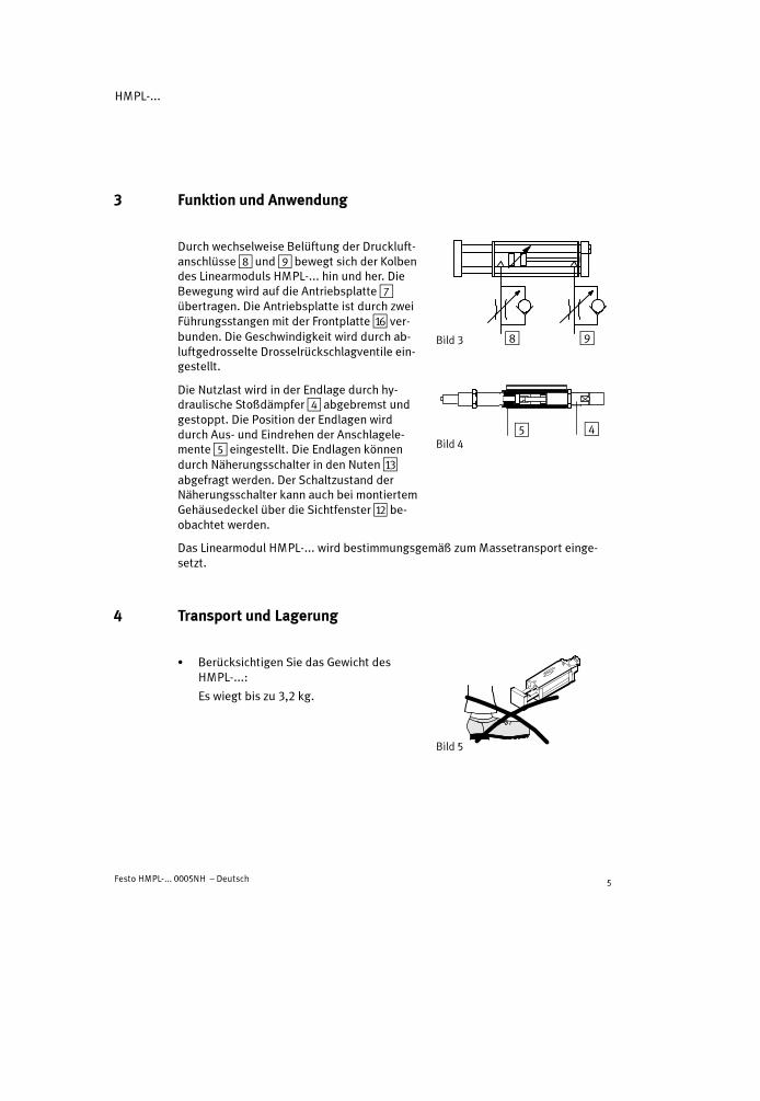
Durch wechselweise Belüftung der Druckluft-anschlüsse8 und9 bewegt sich der Kolbendes Linearmoduls HMPL-... hin und her. DieBewegung wird auf die Antriebsplatte7übertragen. Die Antriebsplatte ist durch zweiFührungsstangen mit der Frontplatte aF ver-bunden. Die Geschwindigkeit wird durch ab-luftgedrosselte Drosselrückschlagventile ein-gestellt.
Die Nutzlast wird in der Endlage durch hy-draulische Stoßdämpfer4 abgebremst undgestoppt. Die Position der Endlagen wirddurch Aus- und Eindrehen der Anschlagele-mente5 eingestellt. Die Endlagen könnendurch Näherungsschalter in den Nuten aCabgefragt werden. Der Schaltzustand derNäherungsschalter kann auch bei montiertemGehäusedeckel über die Sichtfenster aB be-obachtet werden.
Das Linearmodul HMPL-... wird bestimmungsgemäß zumMassetransport einge-setzt.
4 Transport und Lagerung
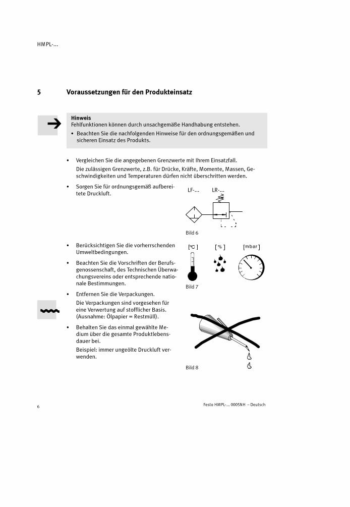
� Berücksichtigen Sie das Gewicht desHMPL-...:
Es wiegt bis zu 3,2 kg.
Bild 3 8 9
Bild 445
Bild 5
HMPL-...
Festo HMPL-... 0005NH – Deutsch6
5 Voraussetzungen für den Produkteinsatz
HinweisFehlfunktionen können durch unsachgemäße Handhabung entstehen.
� Beachten Sie die nachfolgenden Hinweise für den ordnungsgemäßen undsicheren Einsatz des Produkts.
� Vergleichen Sie die angegebenen Grenzwerte mit Ihrem Einsatzfall.
Die zulässigen Grenzwerte, z.B. für Drücke, Kräfte, Momente, Massen, Ge-schwindigkeiten und Temperaturen dürfen nicht überschritten werden.
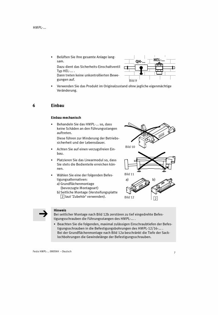
� Sorgen Sie für ordnungsgemäß aufberei-tete Druckluft.
� Berücksichtigen Sie die vorherrschendenUmweltbedingungen.
� Beachten Sie die Vorschriften der Berufs-genossenschaft, des Technischen Überwa-chungsvereins oder entsprechende natio-nale Bestimmungen.
� Entfernen Sie die Verpackungen.
Die Verpackungen sind vorgesehen füreine Verwertung auf stofflicher Basis.(Ausnahme: Ölpapier = Restmüll).
� Behalten Sie das einmal gewählte Me-dium über die gesamte Produktlebens-dauer bei.
Beispiel: immer ungeölte Druckluft ver-wenden.
Bild 6
LF-... LR-...
Bild 7
Bild 8
HMPL-...
Festo HMPL-... 0005NH – Deutsch 7
� Belüften Sie Ihre gesamte Anlage lang-sam.
Dazu dient das Sicherheits-EinschaltventilTyp HEL-... .Dann treten keine unkontrollierten Bewe-gungen auf.
� Verwenden Sie das Produkt im Originalzustand ohne jegliche eigenmächtigeVeränderung.
6 Einbau
Einbau mechanisch
� Behandeln Sie das HMPL-... so, dasskeine Schäden an den Führungsstangenauftreten.
Diese führen zur Minderung der Betriebs-sicherheit und der Lebensdauer.
� Achten Sie auf einen verzugsfreien Ein-bau.
� Platzieren Sie das Linearmodul so, dassSie stets die Bedienteile erreichen kön-nen.
� Wählen Sie eine der folgenden Befes-tigungsalternativen:a) Grundflächenmontage
(bevorzugte Montageart)b)Seitliche Montage (Versteifungsplatte
2 laut ’Zubehör’ verwenden).
HinweisBei seitlicher Montage nach Bild 12b zerstören zu tief eingedrehte Befes-tigungsschrauben die Führungsstangen des HMPL-... .
� Beachten Sie die folgenden, maximal zulässigen Einschraubtiefen der Befes-tigungsschrauben in die Befestigungsbohrungen des HMPL-12/16-... .Bei der Grundflächenmontage nach Bild 12a beschränkt die Tiefe der Sack-lochbohrungen die Gewindelänge der Befestigungsschrauben.
Bild 9
Bild 10
Bild 11
Bild 12
a) b)
2
HMPL-...
Festo HMPL-... 0005NH – Deutsch8
Nenn-���� HMPL-12-... HMPL-16-...
Nennweite M 5 M 5
Max. zul. Einschraubtiefe 8 mm 9 mm
Bild 13
Zusätzliche Hinweise zur Montage in Verbindung mit Komponenten von Festosind in der Systembeschreibung ’Handhabungstechnik’ zusammengefasst.
Neben der Direktbefestigung an den Gewindebohrungen1 kann das HMPL-...mit einer Schwalbenschwanz-Adapterplatte gemäß Zubehör befestigt werden.
Zur genauen Ausrichtung bei der Montage:
� Verwenden Sie die beiliegenden Zentrierringe.
� Drehen Sie die Befestigungsschrauben gleichmäßig fest.
DefinitionBewegliche Masse = Nutzlast + bewegte Eigenmasse + Masse der Befestigungs-elemente
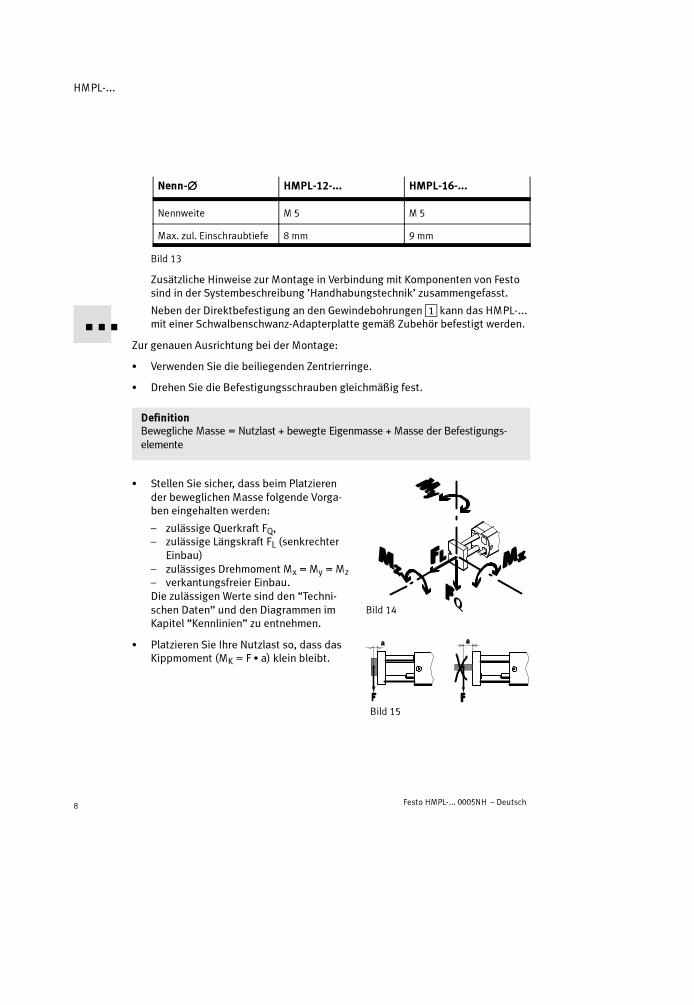
� Stellen Sie sicher, dass beim Platzierender beweglichen Masse folgende Vorga-ben eingehalten werden:
– zulässige Querkraft FQ,– zulässige Längskraft FL (senkrechter
Einbau)– zulässiges Drehmoment Mx = My = Mz– verkantungsfreier Einbau.Die zulässigen Werte sind den “Techni-schen Daten” und den Diagrammen imKapitel “Kennlinien” zu entnehmen.
� Platzieren Sie Ihre Nutzlast so, dass dasKippmoment (MK = F � a) klein bleibt.
Bild 14
Bild 15

HMPL-...
Festo HMPL-... 0005NH – Deutsch 9
� Befestigen Sie die Nutzlast an der Front-platte so, dass sich der Massenschwer-punkt der Nutzlast im Bereich der Front-platte möglichst zwischen denFührungsstangen befindet.
Einbau pneumatisch
� Beachten Sie, dass die Druckluftan-schlüsse abluftgedrosselt sind.
� Verwenden Sie ein 5/2-Wegeventil (inGrundstellung belüftet) zur Ansteuerungdes HMPL-... .
� Verschlauchen Sie die nachfolgendenAnschlüsse (siehe Bild 17):
– A (ausfahrend; schwarzer Schlauch-anschluss QSM-4)
– E (einfahrend; silberner Schlauch-anschluss QSM-4)
– pneumatischer Anschluss der Feststell-einheit (nur bei Linearmodul mit Fest-stelleinheit HMPL-....-KP; siehe sepa-rate Anleitung).
Einbau elektrisch
Bei Einsatz von Näherungsschaltern:
� Vollziehen Sie den Einbau wie folgt:
1. Gehäusedeckel abnehmen und die Nähe-rungsschalter über die Bohrung aA nachinnen führen (nur bei HMPL-...-AI).
2. Näherungsschalter
– in der Nut aC am Anschlagelementplatzieren (siehe Bild 19) und
– in den Endlagenpositionen derHMPL-... justieren und fixieren.
3. Gehäusedeckel wieder befestigen.
Bild 16
Bild 17
Bild 18
aA
Bild 19
aC

HMPL-...
Festo HMPL-... 0005NH – Deutsch10
7 Inbetriebnahme
WarnungVerletzungen können durch plötzlich frei-gesetzte Druckkräfte entstehen.
� Stellen Sie sicher, dass im Verfahrbereichdes HMPL-...
– niemand in die Laufrichtung derbeweglichen Masse greift (z.B. durchSchutzgitter)
– sich keine Fremdgegenständebefinden.
HinweisBei gelösten Stoßdämpfern reduziert sich die Dämpfungsleistung erheblich.
� Stellen Sie sicher, dass die Stoßdämpfer vollständig eingeschraubt undgekontert sind (Auslieferungszustand).
Zur Grob-Einstellung einer Endlagenposition:
� Vollziehen Sie folgende Schritte:
1. HMPL-... entlüften
2. Kontermutter des Anschlagelements miteinem Gabelschlüssel lösen , bis dieBundmutter aD drehbar ist.
3. Bundmutter in der gewünschten Endposi-tion grob positionieren. Die Nut für denNäherungsschalter darf sich dabei nichtunter das Drosselventil schieben.Es sind folgende maximale Endlagen desAnschlagelements zulässig:
– bündig eingeschraubt (Auslieferungs-zustand)
– Gewinde des Anschlagelements stehtmaximal mit der Länge X (sieheBild 23) über.
Bild 20
Bild 21
Bild 22

HMPL-...
Festo HMPL-... 0005NH – Deutsch 11
4. Bundmutter in die Verdrehsicherung zurückschieben und Kontermutter wiederfestdrehen (Anziehdrehmoment der Kontermutter siehe nachfolgende Tabelle).
Nenn-���� HMPL-12-... HMPL-16-... HMPL-20-...
Schlüsselweite 10 13 15
X 15 mm 20 mm
Nm 2 Nm 3 Nm 5 Nm
Bild 23
� Drehen Sie beide vorgeschaltetenDrossel-Rückschlag-Ventile
– zunächst ganz zu– dann wieder eine Umdrehung auf.
� Schieben Sie die Frontplatte von Hand indie eingefahrene Endlage.Dabei ist gleichzeitig die Handbetätigungfür die Klemmeinheit zu drücken (nur beiHMPL-...-KP). Die Klemmeinheit wird da-durch entriegelt.
� Belüften Sie zuerst den Druckluftanschluss:
– der eingefahrenen Endlage E8 am HMPL-... dann– der Klemmeinheit (nur bei HMPL-...-KP).Die bewegliche Masse fährt gegen die Stoßdämpferkraft vollständig in dieeingefahrene Endlage.
� Prüfen Sie, ob die gewünschte Endlagenposition zu verändern ist.
Zur Fein-Einstellung einer Endlagenposition:
� Vollziehen Sie folgende Schritte:
1. Druckluftanschluss der Endlagenpositionlangsam belüften.
2. Gehäusedeckel abnehmen.
3. Kontermutter des Anschlagelements miteinem Gabelschlüssel lösen.
Bild 24
Bild 25
HMPL-...
Festo HMPL-... 0005NH – Deutsch12
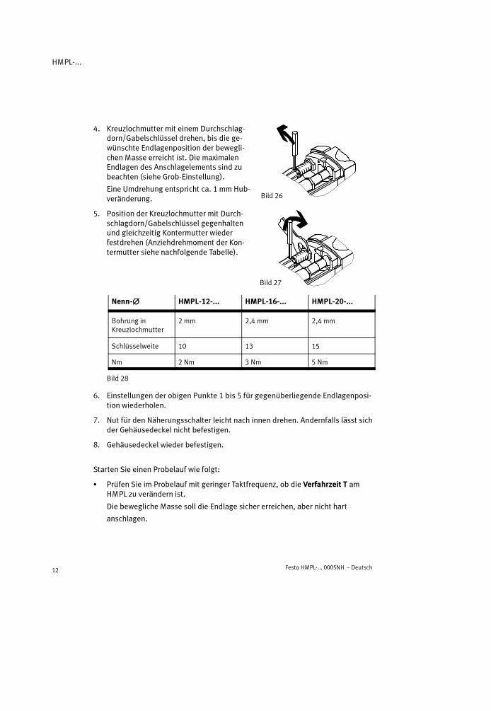
4. Kreuzlochmutter mit einem Durchschlag-dorn/Gabelschlüssel drehen, bis die ge-wünschte Endlagenposition der bewegli-chen Masse erreicht ist. Die maximalenEndlagen des Anschlagelements sind zubeachten (siehe Grob-Einstellung).
Eine Umdrehung entspricht ca. 1 mm Hub-veränderung.
5. Position der Kreuzlochmutter mit Durch-schlagdorn/Gabelschlüssel gegenhaltenund gleichzeitig Kontermutter wiederfestdrehen (Anziehdrehmoment der Kon-termutter siehe nachfolgende Tabelle).
Nenn-���� HMPL-12-... HMPL-16-... HMPL-20-...
Bohrung inKreuzlochmutter
2 mm 2,4 mm 2,4 mm
Schlüsselweite 10 13 15
Nm 2 Nm 3 Nm 5 Nm
Bild 28
6. Einstellungen der obigen Punkte 1 bis 5 für gegenüberliegende Endlagenposi-tion wiederholen.
7. Nut für den Näherungsschalter leicht nach innen drehen. Andernfalls lässt sichder Gehäusedeckel nicht befestigen.
8. Gehäusedeckel wieder befestigen.
Starten Sie einen Probelauf wie folgt:
� Prüfen Sie im Probelauf mit geringer Taktfrequenz, ob die Verfahrzeit T amHMPL zu verändern ist.
Die bewegliche Masse soll die Endlage sicher erreichen, aber nicht hart
anschlagen.
Bild 26
Bild 27

HMPL-...
Festo HMPL-... 0005NH – Deutsch 13
Zur Einstellung der gewünschten Verfahrzeit T:
� Drehen Sie die Drossel-Rückschlag-Ventileauf (abluftgedrosselt), bis die ge-wünschte Verfahrzeit erreicht ist.
Die Drossel mit dem silbernen Schlauch-abgang dient zur Einstellung der Ausfahr-geschwindigkeit (Drehen gegen den Uhr-zeigersinn = Erhöhung der Geschwindig-keit; siehe Bild 29).
Die zulässige Ein- /Ausfahrzeit in Abhängigkeit der Nutzlast ist dem Diagramm imKapitel “Kennlinien” am Ende der Bedienungsanleitung zu entnehmen.
� Beenden Sie den Probelauf.
8 Bedienung und Betrieb
� Berücksichtigen Sie, dass während der Betriebsdauer die Viskosität des Stoß-dämpferöls durch die entstehende Reibungswärme abnimmt.
Der Stoßdämpfer kann somit bei erhöhter Betriebsdauer durchschlagen.
Bei Temperaturen um 0 °C:
� Beachten Sie, dass die Rückstellzeiten des Stoßdämpfers länger werden.
Tiefe Temperaturen bewirken eine Viskositätszunahme des Hydrauliköls.
Bild 29

HMPL-...
Festo HMPL-... 0005NH – Deutsch14
� Prüfen Sie die Dämpfungselemente auf folgende Verschleißanzeichen:
Dämpfungselement Stoßdämpfer 4444 Gummipuffer aaaaDDDD
Prüfungszyklus Alle 2 Mio. Hübe Alle 2 Mio. Hübe
Verschleißanzeichen Ölleckage;hartes Anschlagen;Anschlagstößel (15)bleibt in eingefahrenerEndlage stehen / bewegtsich langsam heraus
Starke Geräusche
Austauschzyklus Alle 10 Mio. Hübe Alle 5 Mio. Hübe
Bild 30
Die bewegliche Masse soll die Endlagen stets sicher erreichen, aber nicht hartanschlagen.
� Prüfen Sie die Notwendigkeit kürzerer Prüfintervalle. Das kann notwendig seinbei:
– hoher Temperaturbelastung– starkem Schmutzanfall– Nähe fettlösender Flüssigkeiten oder Dämpfe.
9 Wartung und Pflege
� Reinigen Sie im Falle von Verschmutzungen das HMPL-... mit einem weichenLappen.
Zulässige Reinigungsmedien sind:
– Seifenlauge (max. + 60 °C)– alle werkstoffschonenden Medien.

HMPL-...
Festo HMPL-... 0005NH – Deutsch 15
10 Ausbau und Reparatur
Zum Austausch eines Stoßdämpfers:
1. HMPL-... entlüften.
2. Gehäusedeckel abnehmen.
3. Kontermutter am Stoßdämpfer4 lösen.
4. Stoßdämpfer ausdrehen (Schlüsselfläche(A) am Stoßdämpfer vorhanden).
5. Verbindungsclip (B), falls auf Stoßdämp-fer verblieben, abziehen und auf neuenStoßdämpfer aufdrücken.
6. Neuen Stoßdämpfer bis zum Anschlag eindrehen.
7. Kontermutter am Stoßdämpfer wieder festdrehen (Anziehdrehmoment siehe“Inbetriebnahme”).
8. Endlagenposition langsam be- und entlüften (Verbindungsclip rastet ein).
9. Gehäusedeckel wieder befestigen.
10. Wiederinbetriebnahme durchführen (gemäß Kapitel “Inbetriebnahme”).
� Sorgen Sie für eine Verwertung des Stoßdämpfers unter Berücksichtigung desUmweltschutzes (Problemstoff-Verwertung).
Der Stoßdämpfer ist gefüllt mit Hydrauliköl. Sein Konstruktionsprinzip ver-wehrt das Nachfüllen.
Bei Bedarf:
� Sorgen Sie dafür, dass eine Überholung des HMPL-... nur durch unseren Repa-raturservice vorgenommen wird.
Zum Ausbau des HMPL-...:
� Entlüften Sie die gesamte Anlage und das Gerät.
� Bestellen Sie die angegebenen Verschleißteile nach, wenn Ihr HMPL-... dieaufgeführten Anzeichen zeigt.
Bild 31
4
(A)(B)
HMPL-...
Festo HMPL-... 0005NH – Deutsch16
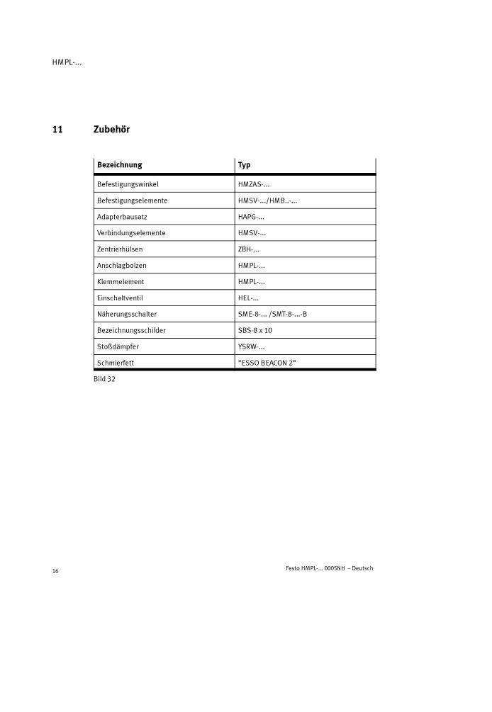
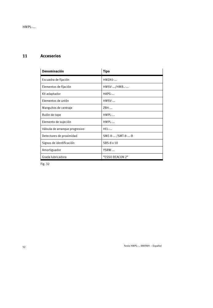
11 Zubehör
Bezeichnung Typ
Befestigungswinkel HMZAS-...
Befestigungselemente HMSV-.../HMB..-...
Adapterbausatz HAPG-...
Verbindungselemente HMSV-...
Zentrierhülsen ZBH-...
Anschlagbolzen HMPL-...
Klemmelement HMPL-...
Einschaltventil HEL-...
Näherungsschalter SME-8-... /SMT-8-...-B
Bezeichnungsschilder SBS-8 x 10
Stoßdämpfer YSRW-...
Schmierfett ”ESSO BEACON 2”
Bild 32

HMPL-...
Festo HMPL-... 0005NH – Deutsch 17
12 Störungsbeseitigung
Störung mögliche Ursache Abhilfe
UngleichförmigeBewegung desLinearmoduls
Drosselrückschlagventilefalsch eingesetzt
Möglichst Abluft drosseln(Auslieferungszustand)
Hartes Anschlagen ind Hub dl g
Stoßdämpfer defekt Stoßdämpfer austauschender Hubendlage
Linearmodul überlastet Geschwindigkeit reduzieren
Lautes Anschlagen inder Hubendlage
Gummipuffer verschlissen Gummipuffer austauschen(nur bei HMPL-16/20-...)
Störungen bei derPositionsabfrage
Position der Näherungs-schalter falsch
Position der Näherungsschalterkorrigieren
Falscher Näherungs-schalter-Typ eingesetzt
Nur Näherungsschalter vomTyp SME/SMT-8-...-B verwenden
Näherungsschalter defekt Näherungsschalter tauschen
Ferritische Teile in derNähe des Näherungs-schalters
Teile aus nichtmagnetischenWerkstoffen einsetzen
Starke Leckage HMPL-... verspannteingebaut
HMPL-... auf ebenem Untergrundbefestigen
Dichtungen verschlissen Verschleißteile ersetzen– selbst mit Verschleißteilesatz– zur Reparatur an Festo
schicken
HMPL-... erreichti ht di g ü ht
Drosseln geschlossen Drosseln aufdrehennicht die gewünschteGeschwindigkeit Fehlendes Luftvolumen Anschlussquerschnitte vergrö-
ßern, Volumen vorschalten
Druck zu gering HMPL-... mit min. 4 bar belüften
Hohe Reibung oderGegenkraft
Größeres Linearmodul wählen
Bild 33

HMPL-...
Festo HMPL-... 0005NH – Deutsch18
13 Technische Daten
Typ HMPL-...
12-... 16-... 20-...
Einbaulage Beliebig
Bauart Doppeltwirkender Pneumatik-Zylinder mit Stangen-führung
Medium gefilterte Druckluft, geölt oder ungeölt (Filterfeinheit40 �m)
Bei Geschwindigkeitenüber 1 m/s
Zwingend geölte Druckluft verwenden
Betriebsdruckbereich Mindestens 4 ... max. 8 bar
Anschlussgewinde M5
Zulässiger Temperatur-bereich
0 �C ... max. + 60 �C
Theoretische Nutzkraft bei6 bar – ausfahrend
– einfahrend51 N68 N
104 N121 N
158 N188 N
Theoretischer Luftver-brauch bei 6 bar(pro 10 mm Hub)
– ausfahrend– einfahrend
0,007 NL0,008 NL
0,012 NL0,014 NL
0,018 NL0,022 NL
Normalleckage Kleiner 2 Nl/h (im Neuzustand, gemessen bei 6 bar)
Wiederholgenauigkeit*) � 0,02 mm
Endlagendämpfung Hydraulische Dämpfung
Dämpfungslänge 7,5 mm 9,5 mm 13,5 mm
Max. Zusatzmasse– horizontale Einbaulage– vertikale Einbaulage
2 kg1 kg
5 kg2,5 kg
10 kg5 kg

HMPL-...
Festo HMPL-... 0005NH – Deutsch 19
Typ
20-...16-...12-...
Zulässige Längskraft FL **)
(senkrechter Einbau)25 N 40 N 75 N
Zulässige statische Kipp-momente (Mx = My) an derKolbenstange desHMPL-...**)
0,7 Nm 1,5 Nm 2,5 Nm
Werkstoffe Zylinderprofil, Frontplatte,Abschlussdeckel, Lagerdeckel,Anschlagelementprofil : AlSchrauben, Kolbenstange: StBolzen, Führungsstange: St (gehärtet)Schmutzabstreifer: P 5010Klebstoffe: LoctiteKolben, O-Ringe, Dichtungen: NBR/PUVerschlussstopfen: PA 6Sichtfenster: PC
Ca. Gewicht ***)
– Hub = 0 mm– pro 10 mm Hub
0,5 kg0,04 kg
0,7 kg0,05 kg
1 kg0,07 kg
*) Während 100 aufeinanderfolgenden Hüben unter konstanten Betriebsbedingungen**) Bezugssystem siehe Kapitel “Einbau mechanisch”***)Masse steigt mit Hub nicht linear an
14 Kennlinien (am Ende der Bedienungsanleitung)

HMPL-...
Festo HMPL-... 0005NH – Deutsch20

HMPL-...
Festo HMPL-... 0005NH – English 21
Pneumatic linear module type HMPL-...-...English
1 Operating parts and connections
1 2 3 4 5 6 7 8 9
aJ
aA
aB
aCaDaEaFaG
1 Threaded holes with centring groove for fastening the linear module
2 Bracing plate (accessory)
3 Compressed air connection with exhaust restrictor
4 Shock absorber for end position cushioning
5 Stop element for setting the end position (secured with locking nuts)Internal mounting position with HMPL-...-AIExternal mounting position with HMPL-...-AE

HMPL-...
Festo HMPL-... 0005NH – English22
6 Capstan nut for setting the end position
7 Drive plate
8 Silver hose with plug connector type QSM-4 (= return stroke)
9 Black hose with plug connector type QSM-4 (= advance stroke)
aJ Connector cap (PG16) for cable protection tubing
aA Through hole for cable exit
aB Housing cover with viewing window
aC Groove for proximity switch
aD Collar nut
aE Stop plunger with rubber buffer
aF Front plate
aG Threaded holes with centring groove for fastening the work load
Fig. 1
2 Product summary
Fig. 2

HMPL-...
Festo HMPL-... 0005NH – English 23
3 Method of operation and use
When the compressed air connections arepressurized alternately8 and9, a piston onthe linear module type HMPL-... moves back-wards and forwards. The movement is trans-ferred to the drive plate7. The drive plate isconnected to the front plate aF by means oftwo guide rods. The speed is set by means ofexhaust-restricted one-way flow controlvalves.
The work load is braked and stopped in theend position by hydraulic shock absorbers4.You can set the end positions by screwing thestop elements in and out5. The end posi-tions can be detected by means of proximityswitches in the grooves aC . The switchingstatus of the proximity switches can be ob-served through the viewing window aB whenthe housing cover is fitted on.
The HMPL-... linear module is intended for transporting masses.
4 Transport and storage
� Take the weight of the HMPL-... into con-sideration.
It weights up to 3.2 kg.
Fig. 3 8 9
Fig. 445
Fig. 5

HMPL-...
Festo HMPL-... 0005NH – English24
5 Conditions of use
Please noteIncorrect handling can lead to malfunctioning.
� These general conditions for the correct and safe use of the product must beobserved at all times.
� Compare the maximum values specified with those of your application.
The maximum permitted values, e.g. for pressures, forces, torques, masses,speeds and temperatures must not be exceeded.
� Ensure that there is a supply of correctlyprepared compressed air.
� Please observe the prevailing ambientconditions.
� Please comply with national and localsafety laws and regulations.
� Remove all packaging.
The packaging is intended for recycling.(Exception: oiled paper: this must be dis-posed of ).
� Maintain the selected medium for thecomplete service life of the product.
Example: If non-lubricated compressed airis used at the beginning, you should al-ways use non-lubricated compressed air.
Fig. 6
LF-... LR-...
Fig. 7
Fig. 8

HMPL-...
Festo HMPL-... 0005NH – English 25
� Slowly pressurize the complete system.
To do this use safety start-up valve typeHEL-... .This will prevent uncontrolled movementsfrom occurring.
� Unauthorized product modification is notpermitted.
6 Fitting
Fitting mechanical components
� Handle the HMPL-... with care so that theguide rod is not damaged.
This would reduce operational reliabilityand the service life.
� Make sure that the HMPL-... is fitted freeof mechanical stress.
� Place the linear module so that you caneasily reach the operating parts.
� Select one of the following fasteningmethods:
a) fitting onto a base surface(preferred method)
b) fitting onto the side (use bracingplate2 as per “Accessories”).
Please noteIf fitted at the side, as shown in Fig. 12b, the fastening screws will damage theguide rods of the HMPL-... if they are screwed in too far.
� Observe the maximum permitted depths for the fastening screws in thefastening holes of the HMPL-12/16-... .If fitted on the base surface as shown in Fig. 12a, the depth of the blind holeswill limit the thread length of the fastening screws.
Fig. 9
Fig. 10
Fig. 11
Fig. 12
a) b)
2
HMPL-...
Festo HMPL-... 0005NH – English26
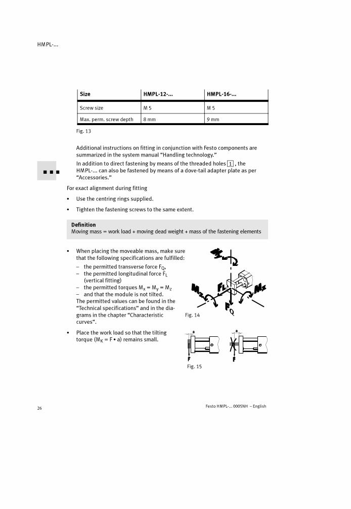
Size HMPL-12-... HMPL-16-...
Screw size M 5 M 5
Max. perm. screw depth 8 mm 9 mm
Fig. 13
Additional instructions on fitting in conjunction with Festo components aresummarized in the systemmanual “Handling technology.”
In addition to direct fastening by means of the threaded holes1 , theHMPL-... can also be fastened by means of a dove-tail adapter plate as per“Accessories.”
For exact alignment during fitting
� Use the centring rings supplied.
� Tighten the fastening screws to the same extent.
DefinitionMoving mass = work load + moving dead weight + mass of the fastening elements
� When placing the moveable mass, make surethat the following specifications are fulfilled:
– the permitted transverse force FQ,– the permitted longitudinal force FL
(vertical fitting)– the permitted torques Mx = My = Mz
– and that the module is not tilted.The permitted values can be found in the“Technical specifications” and in the dia-grams in the chapter “Characteristiccurves“.
� Place the work load so that the tiltingtorque (MK = F � a) remains small.
Fig. 14
Fig. 15

HMPL-...
Festo HMPL-... 0005NH – English 27
� Fasten the work load to the front plate sothat the mass centre of gravity of the workload lies in the area of the front plate, ifpossible between the guide rods.
Fitting pneumatic components
� Make sure that the compressed air con-nections are fitted with exhaust restric-tors.
� Use a 5/2-way valve (pressurized in basicposition) for controlling the HMPL-... .
� Connect the tubing to the following con-nections (see Fig. 17):
– A (extending; black tube connection QSM-4)– E (retracting; silver tube connection QSM-4)– Pneumatic port for the arresting device (only
with linear module with arresting device typeHMPL-....-KP; see separate instructions).
Fitting electric components
Using proximity switches
� If you are using proximity switches, com-plete the fitting as follows:
1. Remove the cover of the housing and in-sert the proximity switches through thehole aA (only with HMPL-...-AI).
2. Proximity switches
– Place the proximity switches in the grooveaC on the stop element (see Fig. 19) and
– adjust and fasten them in the end posi-tions of the HMPL-... .
3. Replace and fasten the cover of the housing.
Fig. 16
Fig. 17
Fig. 18
aA
Fig. 19
aC

HMPL-...
Festo HMPL-... 0005NH – English28
7 Commissioning
WarningThere is a danger of injury caused by thesudden release of pneumatic forces.
� Make sure that:
– nobody can place his/her hand in thepath of the moveable mass (e.g. byproviding a protective grill)
– there are no objects in the positio-ning range of the HMPL-... .
Please noteIf the shock absorbers are loose, the cushioning effect will be considerablyreduced.
� Make sure that the shock absorbers are screwed in completely and locked(as supplied from the factory).
For rough adjustment of an end position:
� Carry out the following steps:
1. Exhaust the HMPL-...
2. Loosen the locking nut of the stop el-ement with an open-ended spanner untilthe flanged nut aD can be turned.
3. Roughly adjust the flanged nut in thedesired end position. The groove for theproximity switch must not be pushedunder the flow control valve.The following maximum end positions ofthe stop element are permitted:
– screwed in flush (as supplied fromfactory)
– the thread of the stop element projectswith maximum length X (see Fig. 23).
Fig. 20
Fig. 21
Fig. 22

HMPL-...
Festo HMPL-... 0005NH – English 29
4. Push the flanged nut back into the non-rotating device and tighten the lockingnut again (tightening torque of the locking nut see table below).
Rated���� HMPL-12-... HMPL-16-... HMPL-20-...
Width across flats 10 13 15
X 15 mm 20 mm
Nm 2 Nm 3 Nm 5 Nm
Fig. 23
� Tighten the two upstream one-way flowcontrol valves
– at first completely– then loosen one turn.
� Push the front plate by hand into the endposition.At the same time you must press the man-ual actuator for the clamping unit (onlywith HMPL-...-KP). The clamping unit willthen be unlocked.
� First pressurize the compressed air port:
– of the retracted end position E8 on the HMPL-..., then– on the clamping unit (only with HMPL-...-KP).The moveable mass now moves completely into the end position against theforce of the shock absorber.
� Check whether the desired endposition needs to be modified.
For precise adjustment of an end position:
� Carry out the following steps:
1. Slowly pressurize the compressed air portof the end position.
2. Remove the cover of the housing.
3. Loosen the locking nut of the stop el-ement with an open-end spanner.
Fig. 24
Fig. 25

HMPL-...
Festo HMPL-... 0005NH – English30
4. Turn the capstan nut with a mandrel/spanner until the desired end position ofthe moveable mass is reached. The maxi-mum end positions of the stop elementmust be observed (see rough adjustment).
One turn corresponds to approx. 1 mmmodification to the stroke.
5. Use a mandrel/spanner to hold the posi-tion of the capstan nut and at the sametime tighten the locking nut again(tightening torque of locking nut see tablebelow).
Rated���� HMPL-12-... HMPL-16-... HMPL-20-...
Hole in capstan nut 2 mm 2.4 mm 2.4 mm
Width across flats 10 13 15
Nm 2 Nm 3 Nm 5 Nm
Fig. 28
6. Repeat the settings of points 1 to 5 above for the opposite end position.
7. Turn the groove for the proximity switch slightly inwards. Otherwise the coverof the housing cannot be fastened.
8. Replace and fasten the cover of the housing.
Start a test run as follows:
� Check with a test run at low speed to ascertain whether the positioning time Ton the HMPL-... needs to be modified.
The moveable mass should reach the end position safely, but not strike hardagainst it.
Fig. 26
Fig. 27

HMPL-...
Festo HMPL-... 0005NH – English 31
Setting the desired positioning time T:
� Open up the one-way flow control valves(exhaust restricted) until the desired posi-tioning time is reached.
The valve with the silver tube exitis used for setting the extension speed(turn in anti-clockwise direction = in-crease speed; see Fig. 29).
The permitted retraction/extension time as a factor of the work load can be foundin the diagram in the chapter “Characteristic curves” at the end of the operatinginstructions.
� Conclude the test run.
8 Operation
� Take into account the fact that the viscosity of the shock absorber oil dimin-ishes during operation due to the friction warmth which arises.
The shock absorber can therefore break through after a long period of oper-ation.
At a temperature of 0 °C:
� Note that the reset times of the shock absorber are longer.
Low temperatures cause an increase in the viscosity of the hydraulic oil.
Fig. 29

HMPL-...
Festo HMPL-... 0005NH – English32
� Check the cushioning elements for the following signs of wear:
Cushioning element Shock absorber 4444 Rubber buffer aaaaDDDD
Test cycle Every 2 million strokes Every 2 million strokes
Sign of wear Oil leak;Hard knocking;Stop plunger (15)remains in end position /moves slowly out
Loud noises
Replacement cycle Every 10 million strokes Every 5 million strokes
Fig. 30
The moveable mass should always reach the end position safely, but not strikehard against it.
� Check whether more frequent tests are required. This may be the case:
– when subjected to high temperatures– when very dirty– when in the vicinity of fat solvent liquids or fumes.
9 Care and maintenance
� If the HMPL-... is dirty, clean it with a soft cloth.
Permitted cleaning agents are:
– soap suds (max. + 60 °C)– all non-abrasive agents.
HMPL-...
Festo HMPL-... 0005NH – English 33
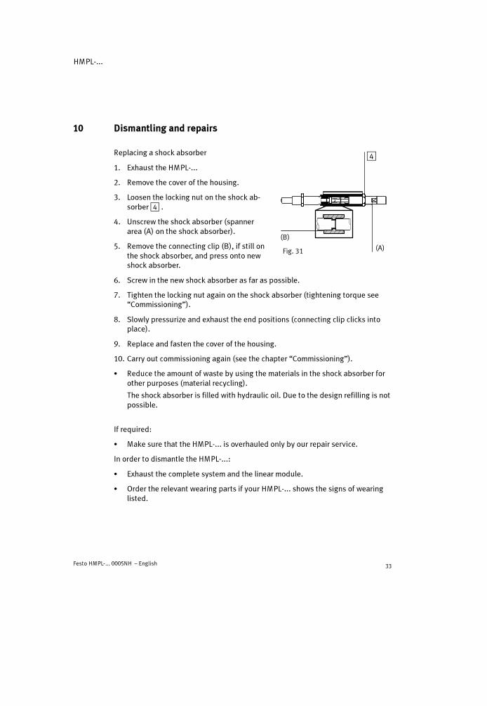
10 Dismantling and repairs
Replacing a shock absorber
1. Exhaust the HMPL-...
2. Remove the cover of the housing.
3. Loosen the locking nut on the shock ab-sorber4 .
4. Unscrew the shock absorber (spannerarea (A) on the shock absorber).
5. Remove the connecting clip (B), if still onthe shock absorber, and press onto newshock absorber.
6. Screw in the new shock absorber as far as possible.
7. Tighten the locking nut again on the shock absorber (tightening torque see“Commissioning”).
8. Slowly pressurize and exhaust the end positions (connecting clip clicks intoplace).
9. Replace and fasten the cover of the housing.
10. Carry out commissioning again (see the chapter “Commissioning”).
� Reduce the amount of waste by using the materials in the shock absorber forother purposes (material recycling).
The shock absorber is filled with hydraulic oil. Due to the design refilling is notpossible.
If required:
� Make sure that the HMPL-... is overhauled only by our repair service.
In order to dismantle the HMPL-...:
� Exhaust the complete system and the linear module.
� Order the relevant wearing parts if your HMPL-... shows the signs of wearinglisted.
Fig. 31
4
(A)
(B)
HMPL-...
Festo HMPL-... 0005NH – English34
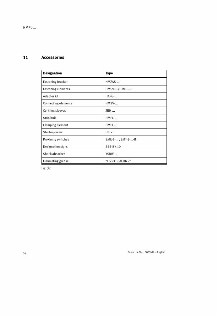
11 Accessories
Designation Type
Fastening bracket HMZAS-...
Fastening elements HMSV-.../HMB..-...
Adapter kit HAPG-...
Connecting elements HMSV-...
Centring sleeves ZBH-...
Stop bolt HMPL-...
Clamping element HMPL-...
Start-up valve HEL-...
Proximity switches SME-8-... /SMT-8-...-B
Designation signs SBS-8 x 10
Shock absorber YSRW-...
Lubricating grease ”ESSO BEACON 2”
Fig. 32

HMPL-...
Festo HMPL-... 0005NH – English 35
12 Eliminating faults
Fault Possible cause Remedy
Uneven movement ofthe linear module
One-way flow controlvalves fitted incorrectly
Restrict the exhaust if possible(as at delivery)
Hard knocking int k d iti
Shock absorber defective Replace shock absorberstroke end position
Linear module overloaded Reduce speed
Hard knocking instroke end position
Rubber buffer worn Replace rubber buffer (only withHMPL-16/20-...)
Faults in positioninterrogation
Position of proximityswitches incorrect
Correct position of proximityswitches
Incorrect type of proximityswitched used
Use only proximity switches oftype SME/SMT-8-...-B
Proximity switch defective Replace proximity switch
Ferritic parts in vicinity ofproximity switch
Use parts made of non-magneticmaterials
Heavy leakage HMPL-... is distorted Fasten the HMPL-... to a flat base
Seals worn Replace worn parts– yourself with wearing parts kit– by returning to Festo for
repairs
HMPL-... does noth th d i d
Flow control valves closed Open up flow control valvesreach the desiredspeed No air volume Increase connection diameters,
switch volume upstream
Pressure too low Pressurize HMPL-... with at least4 bar
High friction or counteract-ing force
Select larger linear module
Fig. 33

HMPL-...
Festo HMPL-... 0005NH – English36
13 Technical specifications
Type HMPL-...
12-... 16-... 20-...
Mounting position As desired
Design Double-acting pneumatic cylinder with rod guiding bush
Medium Filtered compressed air, lubricated or non-lubricated(filter fineness 40 �m)
at speeds above 1 m/s Use lubricated compressed air at all costs
Operating pressure range At least 4 ... max. 8 bar
Connecting thread M5
Permitted temperature range 0 �C ... max. + 60 �C
Theoretical effective powerat 6 bar – extending
– retracting51 N68 N
104 N121 N
158 N188 N
Theoretical air consumptionat 6 bar (per 10 mm stroke)
– extending– retracting
0.007 NL0.008 NL
0.012 NL0.014 NL
0.018 NL0.022 NL
Normal leakage Less than 2 Nl/h (when new, measured at 6 bar)
Repetition accuracy *) � 0.02 mm
End position cushioning Hydraulic cushioning
Cushioning length 7.5 mm 9.5 mm 13.5 mm
Max. additional mass– Horizontal fitting position– Vertical fitting position
2 kg1 kg
5 kg2.5 kg
10 kg5 kg
The permitted longitudinalforce FL **)(vertical fitting) 25 N 40 N 75 N

HMPL-...
Festo HMPL-... 0005NH – English 37
Type
20-...16-...12-...
Permitted static tiltingtorques (Mx = My) on thepiston rod of the HMPL-...**)
0.7 Nm 1.5 Nm 2.5 Nm
Materials Cylinder profile, front plate,end cover, bearing cover,stop element profile: AlScrews, piston rod: StBolts, guide rod: St (hardened)Dirt wiper: P 5010Adhesives: LoctitePistons, O-rings, seals: NBR/PUPlugs: PA 6Viewing window: PC
Approx. weight ***)
– stroke = 0 mm– per 10 mm stroke
0.5 kg0.04 kg
0.7 kg0.05 kg
1 kg0.07 kg
*) During 100 consecutive strokes under constant operating conditions**) Reference system see Chapter “Fitting mechanical components”***)Mass does not increase linear with stroke
14 Characteristic curves (at the end of the operating instructions)

HMPL-...
Festo HMPL-... 0005NH – English38

HMPL-...
Festo HMPL-... 0005NH – Español 39
Módulo lineal neumático tipo HMPL-...Español
1 Elementos funcionales y conexiones
1 2 3 4 5 6 7 8 9
aJ
aA
aB
aCaDaEaFaG
1 Agujeros roscados con ranura de centraje para fijación del módulo lineal
2 Placa de anclaje (accesorio)
3 Conexión de aire comprimido con estrangulación del escape
4 Amortiguador para la posición final
5 Elemento de tope para ajuste de la posición final (asegurado con tuercas de bloqueo)Posición de montaje interna con HMPL-...-AIPosición de montaje externa con HMPL-...-AE

HMPL-...
Festo HMPL-... 0005NH – Español40
6 Tuerca perforada para ajuste de la posición final
7 Placa de accionamiento
8 Tubo plateado con racor tipo QSM-4 (= carrera de retorno)
9 Tubo negro con racor tipo QSM-4 (= carrera de avance)
aJ Tapa del conector (PG16) para tubo de protección del cable
aA Agujero pasante para salida del cable
aB Cubierta del cuerpo con ventana de inspección
aC Ranura para sensor de proximidad
aD Tuerca de collarín
aE Pistón de tope con amortiguador de goma
aF Placa frontal
aG Agujeros roscados con ranura de centraje para fijación de la carga
Fig. 1
2 Resumen del producto
Fig. 2

HMPL-...
Festo HMPL-... 0005NH – Español 41
3 Método de funcionamiento y utilización
Cuando se aplica presión alternativamentea las conexiones8 y9, el émbolo del mó-dulo lineal tipo HMPL-... se desplaza haciaadelante y hacia atrás. El movimiento estransferido a la placa de accionamiento7. Laplaca de accionamiento se halla unida a laplaca frontal aF por medio de dos barras deguía. La velocidad se establece por medio dereguladores de caudal de un sólo sentido.
La carga es frenada y detenida en la posiciónfinal por los amortiguadores hidráulicos4.Pueden ajustarse las posiciones finales enros-cando o desenroscando los elementos detope5. Las posiciones finales pueden con-sultarse por medio de detectores de proximi-dad en las ranuras aC . El estado de conmuta-ción de los detectores de proximidad puedeobservarse a través de la mirilla de inspecciónaB cuando la cubierta se halla montada.
El módulo lineal HMPL-... está previsto para desplazar masas.
4 Transporte y almacenamiento
� Tener en cuenta el peso del HMPL-...
Pesa hasta 3,2 kg.
Fig. 3 8 9
Fig. 445
Fig. 5

HMPL-...
Festo HMPL-... 0005NH – Español42
5 Condiciones de utilización
Por favor, observarUn manejo incorrecto puede producir un mal funcionamiento.
� Estas condiciones generales para el uso seguro y correcto del producto,deben observarse en todo momento.
� Comparar los valores máximos especificados con los de la aplicación.
No deben sobrepasarse los valores máximos permitidos para fuerzas, pares,masas, velocidades y temperaturas.
� Asegurarse de que el aire comprimido sehalla convenientemente preparado.
� Por favor, observar las condiciones am-bientales imperantes.
� Observar las directrices y normas de segu-ridad nacionales y locales establecidas.
� Retirar el embalaje.
El embalaje está previsto para ser reci-clado. (Excepción: papel aceitado: estedebe ser desechado).
� Mantener siempre el mismo fluido paraconseguir una larga vida útil del producto.
Ejemplo: Si al principio se utiliza aire sinlubricar, deberá utilizar siempre aire sinlubricar.
Fig. 6
LF-... LR-...
Fig. 7
Fig. 8

HMPL-...
Festo HMPL-... 0005NH – Español 43
� Aplicar la presión lentamente a todo elsistema.
Para ello, utilizar la válvula de arranqueprogresivo HEL-... .Esto evitará que se produzcan movimien-tos incontrolados.
� No se permiten modificaciones no autori-zadas del producto.
6 Montaje
Montaje de los componentes mecánicos
� Manejar el HMPL-... con cuidado para queno se dañen las barras de guía.
Esto reduciría la fiabilidad de funciona-miento y la vida útil.
� Asegúrese de que el HMPL-.. se montalibre de esfuerzos mecánicos.
� Coloque el módulo lineal de forma quepueda acceder fácilmente a las piezasajustables.
� Elija uno de los siguientes métodos defijación:
a) fijación sobre una superficie de base(método preferido)
b) fijación lateral (utilizar la placade anclaje2 según “Accesorios”).
Por favor, observarSi se monta lateralmente, como muestra la Fig. 12b, los tornillos de fijación puedendañar las barras de guía del HMPL-..., si se atornillan demasiado a fondo.
� Observar las profundidades máximas permitidas para los tornillos de fijaciónen los agujeros del HMPL-12/16-... . Si se montan sobre una superficie debase comomuestra la Fig. 12a, la profundidad de los agujeros ciegos limitarála longitud de la rosca de los tornillos de fijación.
Fig. 9
Fig. 10
Fig. 11
Fig. 12
a) b)
2
HMPL-...
Festo HMPL-... 0005NH – Español44
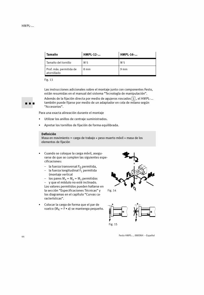
Tamaño HMPL-12-... HMPL-16-...
Tamaño del tornillo M 5 M 5
Prof. máx. permitida deatornillado
8 mm 9 mm
Fig. 13
Las instrucciones adicionales sobre el montaje junto con componentes Festo,están resumidas en el manual del sistema “Tecnología de manipulación”.
Además de la fijación directa por medio de agujeros roscados1 , el HMPL-...también puede fijarse por medio de un adaptador en cola de milano según“Accesorios”.
Para una exacta alineación durante el montaje
� Utilizar los anillos de centraje suministrados.
� Apretar los tornillos de fijación de forma equilibrada.
DefiniciónMasa en movimiento = carga de trabajo + peso muerto móvil + masa de loselementos de fijación
� Cuando se coloque la carga móvil, asegu-rarse de que se cumplen las siguientes espe-cificaciones:
– la fuerza transversal FQ permitida,– la fuerza longitudinal FL permitida
(montaje vertical– los pares Mx = My = Mz permitidos– y que el módulo no esté inclinado.Los valores permitidos pueden hallarse enla sección “Especificaciones Técnicas” ylos diagramas en el capítulo “Curvas ca-racterísticas”.
� Colocar la carga de forma que el par devuelco (MK = F � a) se mantenga pequeño.
Fig. 14
Fig. 15
HMPL-...
Festo HMPL-... 0005NH – Español 45
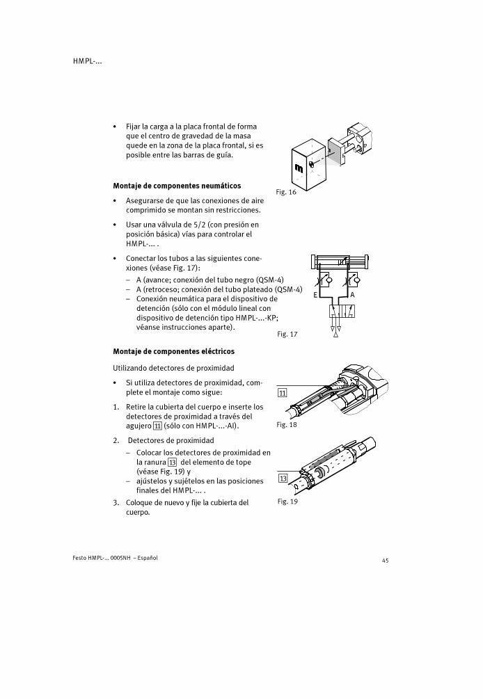
� Fijar la carga a la placa frontal de formaque el centro de gravedad de la masaquede en la zona de la placa frontal, si esposible entre las barras de guía.
Montaje de componentes neumáticos
� Asegurarse de que las conexiones de airecomprimido se montan sin restricciones.
� Usar una válvula de 5/2 (con presión enposición básica) vías para controlar elHMPL-... .
� Conectar los tubos a las siguientes cone-xiones (véase Fig. 17):
– A (avance; conexión del tubo negro (QSM-4)– A (retroceso; conexión del tubo plateado (QSM-4)– Conexión neumática para el dispositivo de
detención (sólo con el módulo lineal condispositivo de detención tipo HMPL-...-KP;véanse instrucciones aparte).
Montaje de componentes eléctricos
Utilizando detectores de proximidad
� Si utiliza detectores de proximidad, com-plete el montaje como sigue:
1. Retire la cubierta del cuerpo e inserte losdetectores de proximidad a través delagujero aA (sólo con HMPL-...-AI).
2. Detectores de proximidad
– Colocar los detectores de proximidad enla ranura aC del elemento de tope(véase Fig. 19) y
– ajústelos y sujételos en las posicionesfinales del HMPL-... .
3. Coloque de nuevo y fije la cubierta delcuerpo.
Fig. 16
Fig. 17
Fig. 18
aA
Fig. 19
aC
HMPL-...
Festo HMPL-... 0005NH – Español46
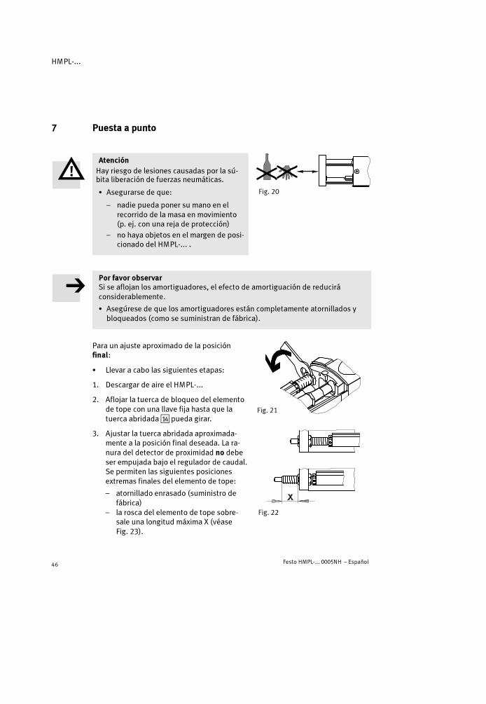
7 Puesta a punto
AtenciónHay riesgo de lesiones causadas por la sú-bita liberación de fuerzas neumáticas.
� Asegurarse de que:
– nadie pueda poner su mano en elrecorrido de la masa en movimiento(p. ej. con una reja de protección)
– no haya objetos en el margen de posi-cionado del HMPL-... .
Por favor observarSi se aflojan los amortiguadores, el efecto de amortiguación de reduciráconsiderablemente.
� Asegúrese de que los amortiguadores están completamente atornillados ybloqueados (como se suministran de fábrica).
Para un ajuste aproximado de la posiciónfinal:
� Llevar a cabo las siguientes etapas:
1. Descargar de aire el HMPL-...
2. Aflojar la tuerca de bloqueo del elementode tope con una llave fija hasta que latuerca abridada aD pueda girar.
3. Ajustar la tuerca abridada aproximada-mente a la posición final deseada. La ra-nura del detector de proximidad no debeser empujada bajo el regulador de caudal.Se permiten las siguientes posicionesextremas finales del elemento de tope:
– atornillado enrasado (suministro defábrica)
– la rosca del elemento de tope sobre-sale una longitud máxima X (véaseFig. 23).
Fig. 20
Fig. 21
Fig. 22

HMPL-...
Festo HMPL-... 0005NH – Español 47
4. Empujar la tuerca abridada hacia el dispositivo antigiro y apretar de nuevo latuerca de bloqueo (véase el par de apriete de la tuerca en la tabla inferior).
���� Nominal HMPL-12-... HMPL-16-... HMPL-20-...
Entrecaras 10 13 15
X 15 mm 20 mm
Nm 2 Nm 3 Nm 5 Nm
Fig. 23
� Apretar los dos reguladores de caudal deun sólo sentido
– primero completamente– a continuación aflojar una vuelta.
� Empujar a mano la placa frontal hacia laposición final.Al mismo tiempo, debe presionar el actua-dor manual de la unidad de sujeción (sólocon HMPL-...-KP). La unidad de sujeciónestará entonces desbloqueada.
� Primero aplicar presión a la conexión de aire:
– de la posición final retraída E8 en el HMPL-..., a continuación– en la unidad de sujeción (sólo con el HMPL-...-KP).La masa en movimiento se desplaza ahora completamente hacia la posiciónfinal en contra de la fuerza del amortiguador.
� Verificar si la posición final deseada debe ser modificada.
Para un ajuste preciso de la posición final:
� Llevar a cabo las siguientes etapas:
1. Aplicar presión lentamente a la conexiónde aire para la posición final.
2. Retirar la cubierta del cuerpo.
3. Aflojar la tuerca de bloqueo del elementode tope con una llave hexagonal.
Fig. 24
Fig. 25

HMPL-...
Festo HMPL-... 0005NH – Español48
4. Girar la tuerca agujereada con un punzón/llave fija hasta alcanzar la posición finaldeseada de la masa. Deben observarselas posiciones finales máximas del ele-mento de tope (véase ajuste aproximado).
Una vuelta corresponde a aprox. 1 mm demodificación de la carrera.
5. Utilizar un punzón/llave fija para sostenerla posición de la tuerca agujereada y almismo tiempo apretar de nuevo la tuercade bloqueo (par de apriete de la tuerca debloqueo, ver tabla inferior).
���� Nominal HMPL-12-... HMPL-16-... HMPL-20-...
Agujero en tuercacon taladros
2 mm 2,4 mm 2,4 mm
Entrecaras 10 13 15
Nm 2 Nm 3 Nm 5 Nm
Fig. 28
6. Repetir los ajustes de los puntos 1 a 5 citados, para la posición final opuesta.
7. Girar la ranura para del detector de proximidad ligeramente hacia adentro. Delo contrario, la cubierta del cuerpo no puede fijarse.
8. Coloque de nuevo y fije la cubierta del cuerpo.
Inicie una prueba como sigue:
� Compruebe con una prueba a baja velocidad para evaluar si el tiempo de posi-cionado T en el HMPL-... debe ser modificado.
La masa en movimiento debería alcanzar siempre con seguridad la posiciónfinal, pero no debería golpear fuerte contra ella.
Fig. 26
Fig. 27

HMPL-...
Festo HMPL-... 0005NH – Español 49
Ajuste del tiempo de posicionado T deseado:
� Abrir las válvulas reguladoras de caudal(escape restringido) hasta que se alcanceel tiempo de posicionado deseado.
La válvula con la salida por el tuboplateado se utiliza para ajustar la veloci-dad de avance (giro antihorario = másvelocidad; véase la Fig. 29).
El tiempo de avance/retroceso permitido en función de la carga, puede hallarse enel diagrama del capítulo “Curvas características“ al final de las instrucciones defuncionamiento.
� Finalizar el funcionamiento de prueba.
8 Funcionamiento
� Tener en cuenta el hecho que la viscosidad del aceite hidráulico del amortigua-dor disminuye durante el funcionamiento debido al calentamiento por fricciónque se produce.
Por ello, el amortiguador puede deteriorarse tras un largo período de funcio-namiento.
A una temperatura de 0 °C:
� Observar que los tiempos de reposición del amortiguador son más largos.
Las bajas temperaturas pueden causar un aumento en la viscosidad del aceitehidráulico.
Fig. 29

HMPL-...
Festo HMPL-... 0005NH – Español50
� Verificar los signos de desgaste en los elementos amortiguadores siguientes:
Elemento deamortiguación
Amortiguador 4444 Tope de goma aaaaDDDD
Ciclo de test Cada 2 millones de carreras Cada 2 millones de carreras
Signos de desgaste Fugas de aceite;Golpe seco;El pistón de tope (15) per-manece en posición final/se desplaza lentamentehacia afuera
Ruidos elevados
Ciclo de sustitución Cada 10 millones de carreras Cada 5 millones de carreras
Fig. 30
La masa en movimiento debería alcanzar siempre con seguridad la posiciónfinal, pero no debería golpear fuerte contra ella.
� Comprobar si se requieren verificaciones con más frecuencia. Este puede ser elcaso:– cuando está sujeto a elevadas temperaturas– en entornos muy sucios– si está cerca de disolventes líquidos grasos o de humos.
9 Cuidados y mantenimiento
� Si es necesario, limpiar la parte exterior del HMPL-... con un paño suave.
Los agentes de limpieza permitidos son:
– agua jabonosa (máx. 60 °C)– cualquier agente no abrasivo.

HMPL-...
Festo HMPL-... 0005NH – Español 51
10 Desmontaje y reparaciones
Sustitución del amortiguador
1. Descargar de aire el HMPL-...
2. Retirar la cubierta del cuerpo.
3. Aflojar la tuerca de bloqueo4 en elamortiguador.
4. Desenroscar el amortiguador (zona deplanos (A) en el amortiguador).
5. Retirar el clip de unión (B), si se halla aúnen el amortiguador, y empujarlo en elnuevo amortiguador.
6. Enroscar el nuevo amortiguador todo lo posible.
7. Apretar de nuevo la tuerca de bloqueo y el amortiguador (par de apriete,véase “Puesta a punto”).
8. Aplicar presión y descargar lentamente las posiciones finales (los clips deconexión encajan en sus alojamientos).
9. Coloque de nuevo y fije la cubierta del cuerpo.
10. Realice de nuevo la puesta a punto (véase el capítulo “Puesta a punto”).
� Reducir los desechos utilizando los materiales del amortiguador para otrosfines (reciclado de materiales).
El amortiguador está lleno con aceite hidráulico. Debido a su diseño, no esposible rellenarlo.
Si es necesario:
� Asegúrese de que el HMPL-... sólo es desmontado por nuestro servicio dereparación.
Para desmontar el HMPL-...:
� Descargar de aire completamente el sistema y el módulo lineal.
� Pedir las piezas de desgaste correspondientes si el HMPL-... muestra los sig-nos de desgaste indicados.
Fig. 31
4
(A)
(B)
HMPL-...
Festo HMPL-... 0005NH – Español52
11 Accesorios
Denominación Tipo
Escuadra de fijación HMZAS-...
Elementos de fijación HMSV-.../HMB..-...
Kit adaptador HAPG-...
Elementos de unión HMSV-...
Manguitos de centraje ZBH-...
Bulón de tope HMPL-...
Elemento de sujeción HMPL-...
Válvula de arranque progresivo HEL-...
Detectores de proximidad SME-8-... /SMT-8-...-B
Signos de identificación SBS-8 x 10
Amortiguador YSRW-...
Grada lubricadora ”ESSO BEACON 2”
Fig. 32

HMPL-...
Festo HMPL-... 0005NH – Español 53
12 Eliminación de fallos
Fallo Causa posible Solución
Movimiento irregulardel módulo lineal
Válvulas reguladoras decaudal incorrectamentemontadas
Restringir el escape si es posible(como en la entrega)
Golpe duro en lai ió d fi l d
Amortiguador defectuoso Reemplazar el amortiguadorposición de final decarrera Módulo lineal sobrecar-
gadoReducir la velocidad
Golpe duro en laposición de final decarrera
Tope de goma desgastado Reemplazar el tope de goma(sólo con HMPL-16/20-...)
Fallos en la interroga-ción de la posición
Posición incorrecta de losdetectores de proximidad
Corregir la posición de los detec-tores de proximidad
Se utiliza un tipo incorrectode detectores de proximi-dad
Utilizar sólo detectores de proxi-midad tipo SME/SMT-8-...-B
Detector de proximidaddefectuoso
Reemplazar el detector deproximidad
Piezas ferríticas cerca deldetector de proximidad
Utilizar piezas hechas dematerial no magnético
Fuertes fugas El HMPL-... está forzado Fijar el HMPL-... sobre una baseplana
Juntas desgastadas Reemplazar las piezas desgasta-das– usando un kit de piezas de
recambio– devolviéndolo a Festo para
reparar

HMPL-...
Festo HMPL-... 0005NH – Español54
Fallo SoluciónCausa posible
El HMPL-... noalcanza la velocidadd d
Reguladores de flujocerrados
Abrir los reguladores de flujo
deseadaFalta caudal de aire Aumentar el diámetro de las cone-
xiones, instalar un depósito previo
Presión demasiado baja Aplicar una presiónmínima de4 bar al HMPL-...
Elevada fuerza derozamiento o contraria
Elegir un módulo lineal mayor
Fig. 33
13 Especificaciones técnicas
Tipo HMPL-...
12-... 16-... 20-...
Posición de montaje Indiferente
Construcción Cilindro neumático de doble efecto con vástagoguiado
Fluido Aire comprimido filtrado (mín. 40 �m) con o sinlubricación
A velocidades superiores a 1 m/s Usar siempre aire comprimido lubricado
Margen de presión de funciona-miento
Entre 4 y 8 bar
Rosca de conexión M5
Margen de temperaturas perm. 0 �C ... máx. + 60 �C
Fuerza teórica efectiva a 6 bar– avance– retroceso
51 N68 N
104 N121 N
158 N188 N

HMPL-...
Festo HMPL-... 0005NH – Español 55
Tipo
20-...16-...12-...
Consumo teórico de aire a 6 bar(por 10 mm de carrera)
– avance– retroceso
0,007 NL0,008 NL
0,012 NL0,014 NL
0,018 NL0,022 NL
Fugas normales Menos de 2 NL/h (estando nuevo, medidas a 6 bar)
Repetibilidad *)� 0,02 mm
Amortiguación final de recorrido Amortiguación hidráulica
Longitud de amortiguación 7,5 mm 9,5 mm 13,5 mm
Máx. carga adicional– Posición de montaje horizontal– Posición de montaje vertical
2 kg1 kg
5 kg2,5 kg
10 kg5 kg
La fuerza longitudinal permi-tida FL **)(montaje vertical) 25 N 40 N 75 N
Pares de vuelco estático permiti-dos (Mx = My) en el vástago delHMPL-...**)
0,7 Nm 1,5 Nm 2,5 Nm
Materiales Perfil del cilindro, placa frontal,cubierta final, cubierta de apoyoperfil del elemento de tope: AlTornillos, vástago: AceroBulones, vástago guía: Acero (endurecido)Rascadora: P 5010Adhesivos: LoctitePistones, juntas tóricas, juntas: NBR/PURacores: PA 6Mirilla de inspección: PC
Peso aproximado ***)
– carrera = 0 mm– por cada 10 mm de carrera
0,5 kg0,04 kg
0,7 kg0,05 kg
1 kg0,07 kg
*) Durante 100 carreras consecutivas bajo condiciones de funcionamiento constantes**) Sistema de referencia, véase Capítulo “Montaje de los componentes mecánicos”***)La masa no aumenta con la carrera lineal

HMPL-...
Festo HMPL-... 0005NH – Español56
14 Curvas características (al final de las instrucciones de funcionamiento)
HMPL-...
Festo HMPL-... 0005NH – Français 57
Module linéaire pneumatique type HMPL-...Français
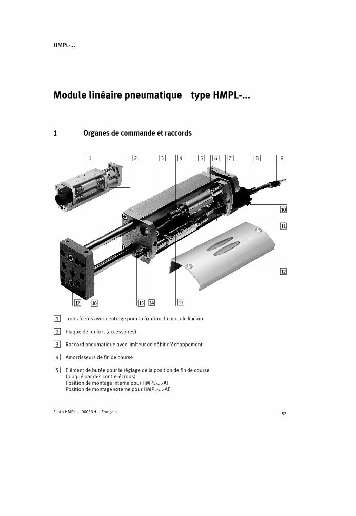
1 Organes de commande et raccords
1 2 3 4 5 6 7 8 9
aJ
aA
aB
aCaDaEaFaG
1 Trous filetés avec centrage pour la fixation du module linéaire
2 Plaque de renfort (accessoires)
3 Raccord pneumatique avec limiteur de débit d’échappement
4 Amortisseurs de fin de course
5 Elément de butée pour le réglage de la position de fin de course(bloqué par des contre-écrous)Position de montage interne pour HMPL-...-AIPosition de montage externe pour HMPL-...-AE

HMPL-...
Festo HMPL-... 0005NH – Français58
6 Ecrou à trous latéraux pour le réglage de la fin de course
7 Plaque d’entraînement
8 Tuyau couleur argent avec raccords de type QSM-4 (= course retour)
9 Tuyau couleur noire avec raccords de type QSM-4 (= course aller)
aJ Capuchon de raccordement (PG16) pour gaine de protection de câble
aA Trou traversant pour le passage de câble
aB Couvercle de corps avec regard
aC Rainure pour capteur de proximité
aD Ecrou d’assemblage
aE Poussoir de butée avec tampon caoutchouc
aF Plaque avant
aG Trous filetés avec centrage pour la fixation de la charge utile
Fig. 1
2 Liste des produits
Fig. 2

HMPL-...
Festo HMPL-... 0005NH – Français 59
3 Fonctionnement et utilisation
Grâce à l’alimentation en alternance des rac-cords pneumatiques8 et9, le piston dumodule linéaire HMPL-... avance et recule. Lemouvement est transmis sur la plaque d’en-traînement7. La plaque d’entraînement estrelié à la plaque avant aF au moyen de deuxcolonnes de guidage. La vitesse est réglée àl’aide de limiteurs de débit d’échappementunidirectionnels.
La charge utile est freinée et arrêtée en fin decourse par des amortisseurs hydrauliques4.Pour régler les fins de course, déplacer leséléments de butée5. Les fins de course peu-vent être détectées par des capteurs de proxi-mité disposés dans les rainures aC. Il est éga-lement possible d’observer l’état de commu-tation des capteurs de proximité par le regard aB.
Le module linéaire de type HMPL-... est prévu pour le transport de masses.
4 Transport et stockage
� Tenir compte du poids du HMPL-... :
Il peut peser jusqu’à 3,2 kg.
Fig. 3 8 9
Fig. 445
Fig. 5
HMPL-...
Festo HMPL-... 0005NH – Français60
5 Conditions préalables à l’utilisation du produit
NoteDes dysfonctionnements peuvent être occasionnés par une manipulation nonconforme.
� Respecter les instructions suivantes relatives à l’utilisation conforme duproduit en toute sécurité.
� Comparer les valeurs limites indiquées avec chaque cas d’utilisation.
Les valeurs limites autorisées, p.ex. de pression, force, couple, masse, vitesseet température, ne doivent en aucun cas être dépassées.
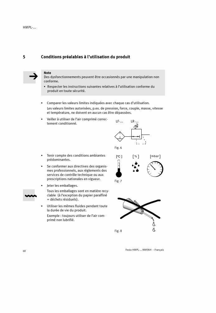
� Veiller à utiliser de l’air comprimé correc-tement conditionné.
� Tenir compte des conditions ambiantesprédominantes.
� Se conformer aux directives des organis-mes professionnels, aux règlements desservices de contrôle technique ou auxprescriptions nationales en vigueur.
� Jeter les emballages.
Tous les emballages sont en matière recy-clable (à l’exception du papier paraffiné= déchets résiduels).
� Utiliser les mêmes fluides pendant toutela durée de vie du produit.
Exemple : toujours utiliser de l’air com-primé non lubrifié.
Fig. 6
LF-... LR-...
Fig. 7
Fig. 8

HMPL-...
Festo HMPL-... 0005NH – Français 61
� Mettre lentement sous pressionl’ensemble de l’installation.
Utiliser pour cela une vanne de mise enpression de sécurité de type HEL-... .Cela empêche que des mouvementsincontrôlés ne se produisent.
� Utiliser le produit dans son état d’origine sans effectuer de modifications nonautorisées.
6 Montage
Montage mécanique
� Manipuler le HMPL-... en veillant à ne pasendommager les colonnes de guidage.
De tels dommages nuisent à la sécurité defonctionnement et réduisent considéra-blement la durée de vie du produit.
� Lors du montage, veiller à ne pas défor-mer les éléments.
� Placer le module linéaire de manière àpouvoir toujours atteindre les organes decommande.
� Pour la fixation, choisir l’une desalternatives suivantes :
a) Montage sur la face de base(type de montage recommandé)
b)Montage latéral (utiliser une plaque derenfort2 conforme aux accessoires).
NoteEn cas de montage latéral selon la figure 12b, veiller à ne pas visser trop profondé-ment les vis de fixation au risque de détruire les tiges de guidage du HMPL-...
� Respecter impérativement les profondeurs de vissage maximales admissiblessuivantes pour les vis de fixation dans les trous de fixation du HMPL-12/16-... .En cas de montage sur embase selon la figure 12a, la profondeur des trousborgnes limite la longueur de filetage des vis de fixation.
Fig. 9
Fig. 10
Fig. 11
Fig. 12
a) b)
2

HMPL-...
Festo HMPL-... 0005NH – Français62
Ø nominal HMPL-12-... HMPL-16-...
Diamètre nominal M 5 M 5
Profondeur de vissagemax. admissible
8 mm 9 mm
Fig. 13
Pour des informations supplémentaires sur le montage en combinaison avecdes composants Festo, se reporter à la description du système “Techniques demanipulation”.
Outre la fixation directe sur les trous filetés1, le HMPL-... peut égalementêtre fixé à l’aide d’une plaque d’adaptation à rainure en queue d’arondeconforme aux accessoires.
Pour un alignement correct lors du montage :
� Utiliser les bagues de centrage fournies.
� Serrer uniformément les vis de fixation.
DéfinitionMasse en mouvement = charge utile + masse propre en mouvement + masse deséléments de fixation
� Veiller à respecter les indications suivan-tes lors du positionnement de la masse enmouvement :
– Force transversale admissible FQ,– Force longitudinale admissible FL
(montage vertical)– Couple admissible Mx = My = Mz
– Réaliser le montage sans forcer.Les valeurs admissibles sont répertoriéesdans les “Caractéristiques techniques” etdans les schémas du chapitre “Courbescaractéristiques“.
� Positionner la charge utile de telle sorteque le couple de basculement (MK = F � a)reste faible.
Fig. 14
Fig. 15

HMPL-...
Festo HMPL-... 0005NH – Français 63
� Fixer la charge utile sur la plaque avant demanière à ce que le centre de gravité de lamasse de la charge utile soit positionnédans la zone de la plaque avant, de préfé-rence entre les colonnes de guidage.
Montage pneumatique
� Tenir compte du fait que le débit des rac-cords pneumatiques est limité à l’échap-pement.
� Utiliser un distributeur 5/2 (alimenté aurepos) pour le pilotage du HMPL-... .
� Brancher les raccords suivants (voir Fig. 17):
– A (sortant ; tuyau de couleur noire QSM-4)– E (entrant ; tuyau de couleur argent QSM-4)– Raccord pneumatique de l’unité de serrage
(uniquement pour module linéaire avecunité de serrage HMPL-....-KP ; voir noticeséparée).
Montage électrique
En cas d’utilisation de capteurs de proximité :
� Procéder au montage de la manière sui-vante :
1. Retirer le couvercle du corps et introduireles capteurs de proximité par le trou aA(uniquement pour HMPL-...-AI).
2. Capteurs de proximité
– Les insérer dans la rainure aC sur l’élé-ment de butée (voir Fig. 19) et les ajus-ter et les fixer dans les positions de finde course du HMPL-....
3. Remettre en place le couvercle du corps.
Fig. 16
Fig. 17
Fig. 18
aA
Fig. 19
aC

HMPL-...
Festo HMPL-... 0005NH – Français64
7 Mise en service
AvertissementDes pressions libérées de façon soudainepeuvent occasionner des blessures.
� Dans la zone de déplacement duHMPL-..., s’assurer
– que personne ne pénètre dans la tra-jectoire de la masse en mouvement(p.ex. par la grille de protection)
– qu’aucun corps étranger ne soitprésent.
NoteEn cas de desserrage des amortisseurs, la capacité d’amortissement est consi-dérablement réduite.
� S’assurer que les amortisseurs sont correctement vissés et bloqués (état à lalivraison).
Pour le réglage approximatif d’une positionde fin de course :
� Procéder de la manière suivante :
1. Mettre le HMPL-... à l’échappement
2. Desserrer le contre-écrou de l’élément debutée à l’aide d’une clé plate jusqu’à ce quel’écrou à embase aD puisse être tourné.
3. Placer approximativement l’écrou à em-base dans la position finale souhaitée. Larainure prévue pour le capteur de proxi-mité ne doit pas être occultée par le limi-teur de débit.Les fins de course maximales admissiblesde l’élément de butée sont les suivantes :
– Montage noyé (état à la livraison)– Le filetage de l’élément de butée ne
doit pas dépasser la longueur X (voirFig. 23).
Fig. 20
Fig. 21
Fig. 22

HMPL-...
Festo HMPL-... 0005NH – Français 65
4. Replacer l’écrou à embase en position de blocage en rotation et serrer lecontre-écrou (pour le couple de serrage du contre-écrou, voir le tableau sui-vant).
���� nominal HMPL-12-... HMPL-16-... HMPL-20-...
Surplat 10 13 15
X 15 mm 20 mm
Nm 2 Nm 3 Nm 5 Nm
Fig. 23
� Fermer les deux limiteurs de débit unidi-rectionnels raccordés en amont
– d’abord complètement,– puis les ouvrir d’un tour.
� Amener à la main la plaque avant en posi-tion finale d’entrée.Pour cela, appuyer en même temps sur lacommande manuelle de l’unité de serrage(uniquement pour HMPL-...-KP). L’unitéde serrage est ainsi déverrouillée.
� Mettre d’abord sous pression le raccord pneumatique :
– de la position finale d’entrée E8 sur le HMPL-... puis– celui de l’unité de serrage (uniquement pour HMPL-...-KP).La masse en mouvement atteint la fin de course d’entrée contre la force del’amortisseur.
� Vérifier si la position de fin de course souhaitée doit être modifiée.
Pour le réglage fin d’une position de fin decourse :
� Procéder de la manière suivante :
1. Mettre lentement sous pression le raccordpneumatique des positions de fin decourse.
2. Retirer le couvercle du corps.
3. Desserrer le contre-écrou de l’élément debutée à l’aide d’une clé plate.
Fig. 24
Fig. 25
HMPL-...
Festo HMPL-... 0005NH – Français66
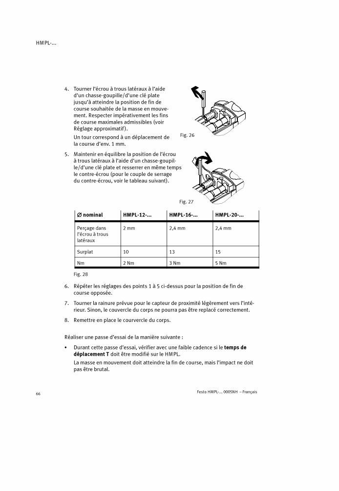
4. Tourner l’écrou à trous latéraux à l’aided’un chasse-goupille/d’une clé platejusqu’à atteindre la position de fin decourse souhaitée de la masse en mouve-ment. Respecter impérativement les finsde course maximales admissibles (voirRéglage approximatif ).
Un tour correspond à un déplacement dela course d’env. 1 mm.
5. Maintenir en équilibre la position de l’écrouà trous latéraux à l’aide d’un chasse-goupil-le/d’une clé plate et resserrer en même tempsle contre-écrou (pour le couple de serragedu contre-écrou, voir le tableau suivant).
���� nominal HMPL-12-... HMPL-16-... HMPL-20-...
Perçage dansl’écrou à trouslatéraux
2 mm 2,4 mm 2,4 mm
Surplat 10 13 15
Nm 2 Nm 3 Nm 5 Nm
Fig. 28
6. Répéter les réglages des points 1 à 5 ci-dessus pour la position de fin decourse opposée.
7. Tourner la rainure prévue pour le capteur de proximité légèrement vers l’inté-rieur. Sinon, le couvercle du corps ne pourra pas être replacé correctement.
8. Remettre en place le courvercle du corps.
Réaliser une passe d’essai de la manière suivante :
� Durant cette passe d’essai, vérifier avec une faible cadence si le temps dedéplacement T doit être modifié sur le HMPL.
La masse en mouvement doit atteindre la fin de course, mais l’impact ne doitpas être brutal.
Fig. 26
Fig. 27
HMPL-...
Festo HMPL-... 0005NH – Français 67
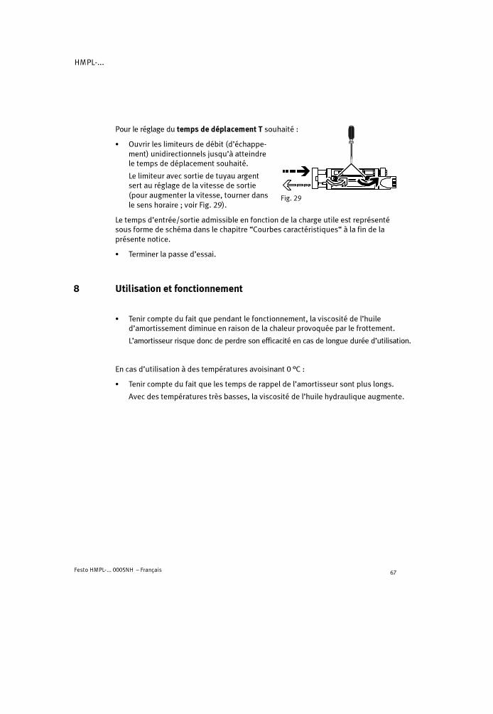
Pour le réglage du temps de déplacement T souhaité :
� Ouvrir les limiteurs de débit (d’échappe-ment) unidirectionnels jusqu’à atteindrele temps de déplacement souhaité.
Le limiteur avec sortie de tuyau argentsert au réglage de la vitesse de sortie(pour augmenter la vitesse, tourner dansle sens horaire ; voir Fig. 29).
Le temps d’entrée/sortie admissible en fonction de la charge utile est représentésous forme de schéma dans le chapitre “Courbes caractéristiques“ à la fin de laprésente notice.
� Terminer la passe d’essai.
8 Utilisation et fonctionnement
� Tenir compte du fait que pendant le fonctionnement, la viscosité de l’huiled’amortissement diminue en raison de la chaleur provoquée par le frottement.
L’amortisseur risque donc de perdre son efficacité en cas de longue durée d’utilisation.
En cas d’utilisation à des températures avoisinant 0 °C :
� Tenir compte du fait que les temps de rappel de l’amortisseur sont plus longs.
Avec des températures très basses, la viscosité de l’huile hydraulique augmente.
Fig. 29

HMPL-...
Festo HMPL-... 0005NH – Français68
� Vérifier les signes d’usure suivants sur les éléments d’amortissement :
Elémentd’amortissement
Amortisseur 4444 Tampon caoutchouc aaaaDDDD
Intervalle de contrôle Tous les 2 mio. de courses Tous les 2 mio. de courses
Signes d’usure Fuite d’huile ; fort impact ;Le poussoir de butée (15)reste en position de fin decourse rentrée / sortlentement
Bruits importants
Cycle deremplacement
Tous les 10 mio. de courses Tous les 5 mio. de courses
Fig. 30
La masse en mouvement doit toujours atteindre les fins de course, mais l’im-pact ne doit pas être brutal.
� Vérifier s’il n’est pas nécessaire de raccourcir les intervalles de contrôle. Celapeut s’avérer nécessaire :
– en cas de température élevée– en cas d’encrassement important– si des liquides ou des vapeurs liposolubles se trouvent à proximité.
9 Maintenance et entretien
� En cas d’encrassement, nettoyer le HMPL-... à l’aide d’un chiffon doux.
Produits de nettoyage autorisés :
– Lessive de savon (max. + 60 °C)– Tous les produits d’entretien de matériaux.

HMPL-...
Festo HMPL-... 0005NH – Français 69
10 Démontage et réparations
Pour le remplacement d’un amortisseur :
1. Mettre le HMPL-... à l’échappement.
2. Retirer le couvercle du corps.
3. Desserrer le contre-écrou sur l’amortis-seur4.
4. Dévisser l’amortisseur (surplat (A) auniveau de l’amortisseur).
5. Retirer le clip de fixation (B), s’il est en-core présent sur l’amortisseur, et l’appli-quer sur le nouvel amortisseur.
6. Visser le nouvel amortisseur jusqu’en butée.
7. Resserrer le contre-écrou sur l’amortisseur (pour le couple de serrage, voir leparagraphe “Mise en service“).
8. Mettre lentement sous pression puis à l’échappement la position de fin decourse (clip de fixation encliqueté).
9. Remettre en place le couvercle du corps.
10. Procéder à la remise en service (voir chapitre “Mise en service”).
� Pour le recyclage de l’amortisseur, tenir compte de la législation en matière deprotection de l’environnement.
L’amortisseur est rempli d’huile hydraulique. Sa conception interdit tout rem-plissage ultérieur.
En cas de nécessité :
� Veiller à ce que toute réparation du HMPL-... ne soit assurée que par nostechniciens.
Pour le démontage du HMPL-...:
� Mettre à l’échappement l’ensemble de l’installation et l’appareil.
� Commander les pièces d’usure indiquées lorsque le HMPL-... présente lessignes d’usure énumérés.
Fig. 31
4
(A)
(B)
HMPL-...
Festo HMPL-... 0005NH – Français70
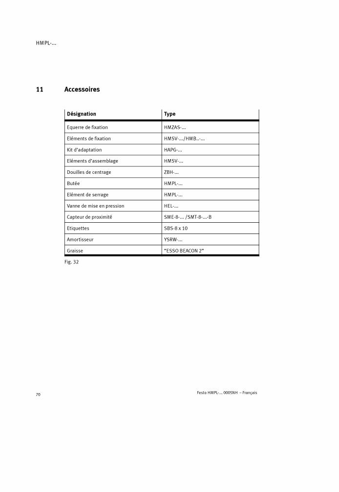
11 Accessoires
Désignation Type
Equerre de fixation HMZAS-...
Eléments de fixation HMSV-.../HMB..-...
Kit d’adaptation HAPG-...
Eléments d’assemblage HMSV-...
Douilles de centrage ZBH-...
Butée HMPL-...
Elément de serrage HMPL-...
Vanne de mise en pression HEL-...
Capteur de proximité SME-8-... /SMT-8-...-B
Etiquettes SBS-8 x 10
Amortisseur YSRW-...
Graisse ”ESSO BEACON 2”
Fig. 32

HMPL-...
Festo HMPL-... 0005NH – Français 71
12 Elimination des incidents
Incident Cause possible Remède
Mouvement irrégu-lier du modulelinéaire
Limiteurs de débit unidi-rectionnels mal installés
Limiter le plus possible le débitd’échappement (état à la livraison)
Impact brutal en find u
Amortisseur défectueux Remplacer l’amortisseur
Impact brutal en find u
Module linéaire surchargé Réduire la vitesse
Impact fort en fin decourse
Tampon caoutchouc usé Remplacer le tampon caoutchouc(uniquement pour HMPL-16/20-...)
Incidents lors de ladétection des posi-ti
Position incorrecte descapteurs de proximité
Corriger la position des capteurs deproximité
tionsType de capteur deproximité incorrect
Utiliser uniquement des capteurs deproximité de type SME/SMT-8-...-B
Capteur de proximitédéfectueux
Remplacer le capteur de proximité
Pièces ferritiques à proxi-mité du capteur de proxi-mité
Utiliser des pièces en matériauxnon magnétiques
Fuites importantes Montage incorrect duHMPL-...
Fixer le HMPL-... sur une surfaceplane
Joints d’étanchéité usés Remplacer les pièces d’usure– soi-même à l’aide du kit de
pièces détachées– retourner à Festo pour toute
réparation
Le HMPL-... n’atteintl it u
Limiteurs de débit fermés Ouvrir les limiteurs de débitpas la vitesse sou-haitée
Débit d’air insuffisant Agrandir les sections des raccords,intercaler un volume en amont
Pression trop faible Alimenter le HMPL-... avec aumoins 4 bar
Frottement ou forceopposée importante
Choisir un module linéaire plusgrand
Fig. 33

HMPL-...
Festo HMPL-... 0005NH – Français72
13 Caractéristiques techniques
Type HMPL-...
12-... 16-... 20-...
Position de montage Indifférente
Type de construction Vérin pneumatique double effet avec colonnes de guidage
Fluide Air comprimé filtré, lubrifié ou non lubrifié (finesse defiltration 40 �m)
En cas de vitessessupérieures à 1 m/s
Utiliser impérativement de l’air comprimé lubrifié
Plage de pression deservice
Min. 4 ... max. 8 bar
Filetage de raccordement M5
Plage de températureadmissible
0 �C ... max. + 60 �C
Charge utile théoriquepour 6 bar – à la sortie
– à l’entrée51 N68 N
104 N121 N
158 N188 N
Consommation d’airthéorique pour 6 bar(pour 10 mm de course)
– à la sortie– à l’entrée
0,007 NL0,008 NL
0,012 NL0,014 NL
0,018 NL0,022 NL
Fuites normales Inférieures à 2 Nl/h (à l’état neuf, pour 6 bar)
Reproductibilité*) � 0,02 mm
Amortissement de fin decourse
Amortissement hydraulique
Longueurd’amortissement
7,5 mm 9,5 mm 13,5 mm
HMPL-...
Festo HMPL-... 0005NH – Français 73
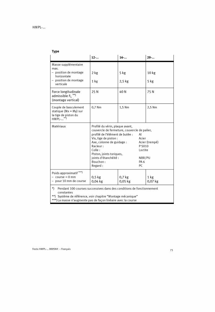
Type
20-...16-...12-...
Masse supplémentairemax.– position de montage
horizontale– position de montage
verticale
2 kg
1 kg
5 kg
2,5 kg
10 kg
5 kg
Force longitudinaleadmissible FL **)
(montage vertical)
25 N 40 N 75 N
Couple de basculementstatique (Mx = My) surla tige de piston duHMPL-...**)
0,7 Nm 1,5 Nm 2,5 Nm
Matériaux Profilé du vérin, plaque avant,couvercle de fermeture, couvercle de palier,profilé de l’élément de butée : AlVis, tige de piston : AcierAxe, colonne de guidage : Acier (trempé)Racleur : P 5010Colle : LoctitePiston, joints toriques,joints d’étanchéité : NBR/PUBouchon : PA 6Regard : PC
Poids approximatif ***)
– course = 0 mm– pour 10 mm de course
0,5 kg0,04 kg
0,7 kg0,05 kg
1 kg0,07 kg
*) Pendant 100 courses successives dans des conditions de fonctionnementconstantes
**) Système de référence, voir chapitre “Montage mécanique”***)La masse n’augmente pas de façon linéaire avec la course

HMPL-...
Festo HMPL-... 0005NH – Français74
14 Courbes caractéristiques (à la fin de la présente notice)

HMPL-...
Festo HMPL-... 0005NH – Italiano 75
Modulo lineare pneumatico tipo HMPL-...Italiano
1 Elementi operativi e attacchi
1 2 3 4 5 6 7 8 9
aJ
aA
aB
aCaDaEaFaG
1 Fori filettati con lamatura di centratura per il fissaggio del modulo lineare
2 Piastra di rinforzo (accessori)
3 Attacco di alimentazione con strozzatura di scarico
4 Deceleratori di fine corsa
5 Elemento d’arresto per la regolazione della posizione di fine corsa (con dado di fissaggio)posizione di montaggio interna per HMPL-...-AIposizione di montaggio esterna per HMPL-...-AE

HMPL-...
Festo HMPL-... 0005NH – Italiano76
6 Dado cilindrico con fori radiali per la regolazione di fine corsa
7 Piastra di azionamento
8 Tubo flessibile argento con connettore a innesto tipo QSM-4 (= corsa di ritorno)
9 Tubo flessibile nero con connettore a innesto tipo QSM-4 (= precorsa)
aJ Cappuccio per collegamenti (PG16) per canalina cavi flessibile
aA Foro passante per passacavo
aB Testata del corpo con finestrella
aC Scanalatura per finecorsa magnetico
aD Dado con spallamento
aE Astina di arresto con elemento elastico
aF Piastra frontale
aG Fori filettati con lamatura di centratura per il fissaggio del carico utile
Fig. 1
2 Descrizione generale del prodotto
Fig. 2

HMPL-...
Festo HMPL-... 0005NH – Italiano 77
3 Funzionamento e utilizzo
L’alimentazione alternata attraverso gliattacchi8 e9 determina lo spostamento delpistone del modulo lineare HMPL-... nelle duedirezioni. Il movimento viene trasmesso allapiastra di azionamento7. La piastra di azio-namento è collegata alla piastra frontale aFmediante due aste di guida. La velocità vieneregolata mediante regolatori di portata discarico unidirezionali.
Il carico utile viene smorzato e fermato nellaposizione di fine corsa mediante ammortizza-tori idraulici4. La posizione di fine corsaviene regolata agendo sugli elementi d’arre-sto5. Le posizioni di finecorsa possono es-sere rilevate dai finecorsa magnetici fissatinelle scanalature aC. Anche con la testata delcorpo montata è possibile controllare lo statodi commutazione del finecorsa magneticoattraverso la finestrella aB.
Il modulo lineare HMPL-... è destinato alla movimentazione di una massa.
4 Trasporto e stoccaggio
� Tenere conto del peso dell’HMPL-...:
Il modulo pesa al massimo 3,2 kg.
Fig. 3 8 9
Fig. 445
Fig. 5

HMPL-...
Festo HMPL-... 0005NH – Italiano78
5 Condizioni di utilizzo
NotaIl cattivo funzionamento può essere dovuto a un utilizzo improprio.
� Per un impiego corretto e sicuro del prodotto attenersi alle seguenti indica-zioni.
� Confrontare i valori-limite indicati con l’applicazione specifica.
Rispettare i valori-limite indicati ad esempio, per pressioni, forze, momenti,masse, velocità e temperature.
� Provvedere a un’adeguata preparazionedell’aria compressa.
� Tenere conto delle condizioni ambientaliesistenti.
� Rispettare le norme dell’associazione dicategoria, del TÜV o eventuali regola-menti nazionali corrispondenti.
� Rimuovere gli imballi.
Gli imballi possono essere riciclati in baseal materiale di cui sono composti. (ecce-zione: carta oleata = rifiuti non riciclabili).
� Una volta scelto un fluido con determi-nate caratteristiche, è necessario utiliz-zarlo per tutta la durata del prodotto.
Esempio: utilizzare sempre aria com-pressa non lubrificata.
Fig. 6
LF-... LR-...
Fig. 7
Fig. 8
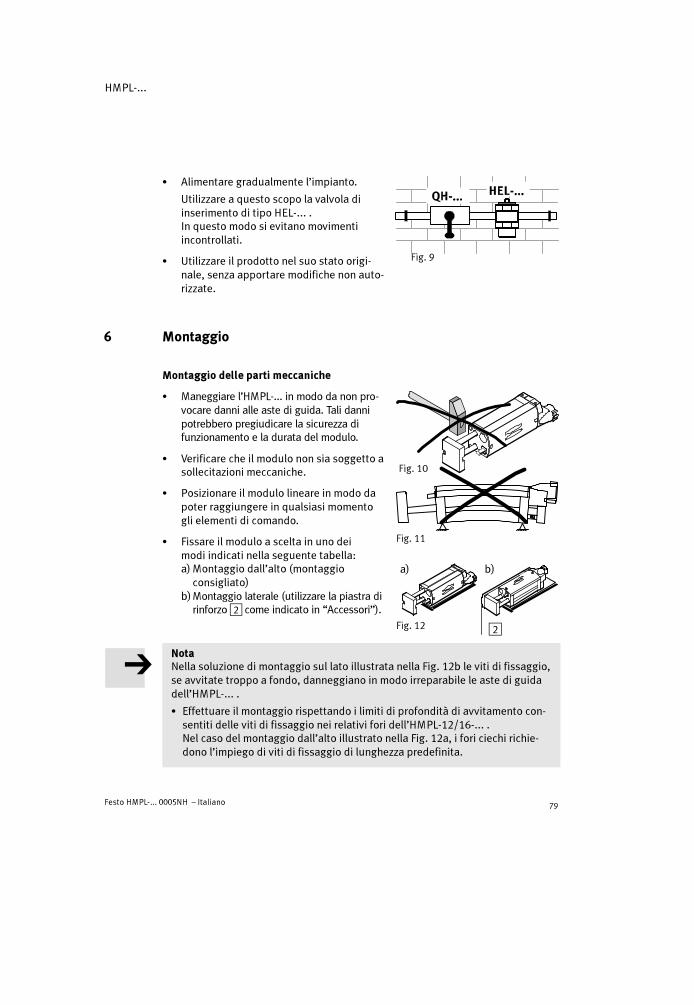
HMPL-...
Festo HMPL-... 0005NH – Italiano 79
� Alimentare gradualmente l’impianto.
Utilizzare a questo scopo la valvola diinserimento di tipo HEL-... .In questo modo si evitano movimentiincontrollati.
� Utilizzare il prodotto nel suo stato origi-nale, senza apportare modifiche non auto-rizzate.
6 Montaggio
Montaggio delle parti meccaniche
� Maneggiare l’HMPL-... in modo da non pro-vocare danni alle aste di guida. Tali dannipotrebbero pregiudicare la sicurezza difunzionamento e la durata del modulo.
� Verificare che il modulo non sia soggetto asollecitazioni meccaniche.
� Posizionare il modulo lineare in modo dapoter raggiungere in qualsiasi momentogli elementi di comando.
� Fissare il modulo a scelta in uno deimodi indicati nella seguente tabella:a) Montaggio dall’alto (montaggio
consigliato)b)Montaggio laterale (utilizzare la piastra di
rinforzo2 come indicato in “Accessori”).
NotaNella soluzione di montaggio sul lato illustrata nella Fig. 12b le viti di fissaggio,se avvitate troppo a fondo, danneggiano in modo irreparabile le aste di guidadell’HMPL-... .
� Effettuare il montaggio rispettando i limiti di profondità di avvitamento con-sentiti delle viti di fissaggio nei relativi fori dell’HMPL-12/16-... .Nel caso del montaggio dall’alto illustrato nella Fig. 12a, i fori ciechi richie-dono l’impiego di viti di fissaggio di lunghezza predefinita.
Fig. 9
Fig. 10
Fig. 11
Fig. 12
a) b)
2

HMPL-...
Festo HMPL-... 0005NH – Italiano80
Diametro nominale HMPL-12-... HMPL-16-...
Alesaggio M 5 M 5
Max. profondità diavvitamento consentita
8 mm 9 mm
Fig. 13
Ulteriori avvertenze sul montaggio in relazione a componenti di Festo sonoraccolte nella descrizione di sistema “Tecnica di manipolazione”.
Oltre al fissaggio diretto mediante i fori filettati1, l’HMPL-... può essere fis-sato mediante una piastra di adattamento a coda di rondine come indicato inAccessori.
Allineamento durante il montaggio:
� Utilizzare gli anelli di centratura in dotazione.
� Stringere uniformemente le viti di fissaggio.
DefinizioneMassa in movimento = carico utile + massa propria spostata + massa degli elementidi fissaggio
� Verificare che durante il posizionamentodella massa in movimento siano rispettatele seguenti condizioni:
– forza trasversale ammissibile FQ,– forza assiale ammissibile FL (in caso di
montaggio verticale)– valore di coppia ammissibile
Mx = My = Mz
– posizione di montaggio perfettamenteallineata.
I valori consentiti sono indicati in “Datitecnici” e nei grafici riportati nel capitolo“Curve caratteristiche“.
� Posizionare il carico utile in modo che lacoppia di ribaltamento (MK = F � a) abbiaun valore basso.
Fig. 14
Fig. 15
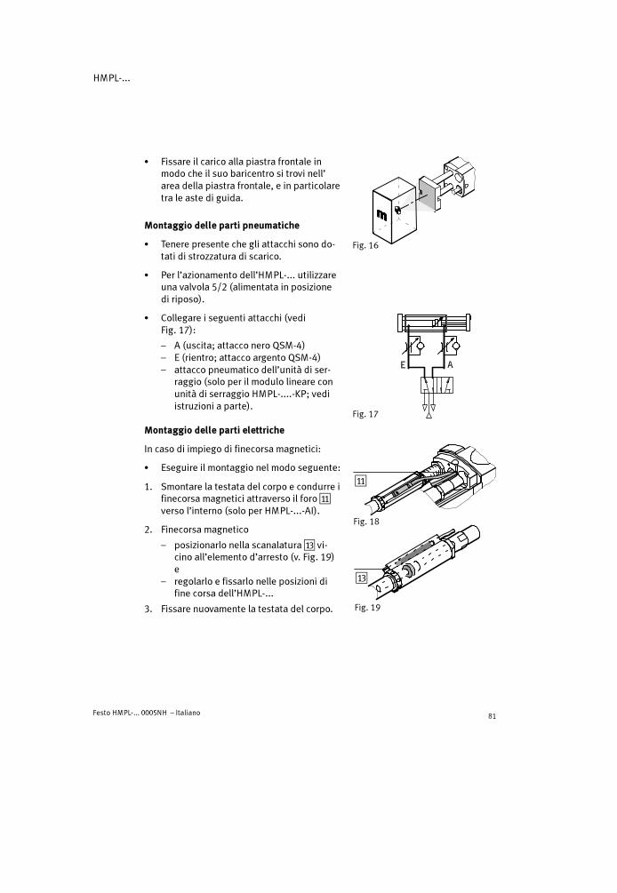
HMPL-...
Festo HMPL-... 0005NH – Italiano 81
� Fissare il carico alla piastra frontale inmodo che il suo baricentro si trovi nell’area della piastra frontale, e in particolaretra le aste di guida.
Montaggio delle parti pneumatiche
� Tenere presente che gli attacchi sono do-tati di strozzatura di scarico.
� Per l’azionamento dell’HMPL-... utilizzareuna valvola 5/2 (alimentata in posizionedi riposo).
� Collegare i seguenti attacchi (vediFig. 17):
– A (uscita; attacco nero QSM-4)– E (rientro; attacco argento QSM-4)– attacco pneumatico dell’unità di ser-
raggio (solo per il modulo lineare conunità di serraggio HMPL-....-KP; vediistruzioni a parte).
Montaggio delle parti elettriche
In caso di impiego di finecorsa magnetici:
� Eseguire il montaggio nel modo seguente:
1. Smontare la testata del corpo e condurre ifinecorsa magnetici attraverso il foro aAverso l’interno (solo per HMPL-...-AI).
2. Finecorsa magnetico
– posizionarlo nella scanalatura aC vi-cino all’elemento d’arresto (v. Fig. 19)e
– regolarlo e fissarlo nelle posizioni difine corsa dell’HMPL-...
3. Fissare nuovamente la testata del corpo.
Fig. 16
Fig. 17
Fig. 18
aA
Fig. 19
aC

HMPL-...
Festo HMPL-... 0005NH – Italiano82
7 Messa in servizio
AvvertenzaLe pressioni che si liberano improvvisa-mente possono causare ferite.
� Assicurarsi che nell’area di movimentodell’HMPL-...
– non sia possibile introdurre le maniper tutta la lunghezza della corsadella massa (ad es. mediante unagriglia di protezione)
– non siano presenti corpi estranei.
NotaIn caso di ammortizzatori allentati si riduce sensibilmente la capacità di ammor-tizzazione.
� Accertarsi che gli ammortizzatori siano completamente avvitati e assicuraticon i controdadi (predisposizione di fabbrica).
Regolazione di massima di una posizione difine corsa:
� Eseguire le seguenti operazioni:
1. Scaricare la pressione dall’HMPL-...
2. Allentare il controdado dell’elemento d’ar-resto con una chiave fissa, fino a quando èpossibile a ruotare il dado con spalla-mento aD.
3. Posizionare il dado con spallamento ap-prossimativamente nella posizione di finecorsa desiderata. La scanalatura per ilfinecorsa magnetico non deve spostarsisotto il regolatore di portata.Sono ammesse le seguenti posizioni difine corsa massime dell’elemento d’arresto:
– avvitato a filo (predisposizione di fabbrica)– la filettatura dell’elemento d’arresto
sporge per la lunghezza massima di X(vedi Fig. 23).
Fig. 20
Fig. 21
Fig. 22
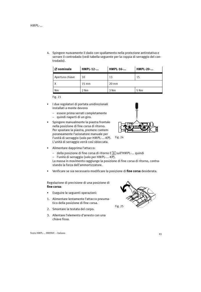
HMPL-...
Festo HMPL-... 0005NH – Italiano 83
4. Spingere nuovamente il dado con spallamento nella protezione antirotativa eserrare il controdado (vedi tabella seguente per la coppia di serraggio del con-trodado).
���� nominale HMPL-12-... HMPL-16-... HMPL-20-...
Apertura chiave 10 13 15
X 15 mm 20 mm
Nm 2 Nm 3 Nm 5 Nm
Fig. 23
� I due regolatori di portata unidirezionaliinstallati a monte devono
– essere prima serrati completamente– quindi riaperti di un giro.
� Spingere manualmente la piastra frontalenella posizione di fine corsa di ritorno.Per spostare la piastra, premere contem-poraneamente l’azionatore manuale perl’unità di serraggio (solo per HMPL-...-KP).L’unità di serraggio verrà così sbloccata.
� Alimentare dapprima l’attacco:
– della posizione di fine corsa di ritorno E8 sull’HMPL-... quindi– l’unità di serraggio (solo per HMPL-...-KP).La massa in movimento raggiunge la posizione di fine corsa di ritorno, contra-stando la forza dell’ammortizzatore.
� Verificare se sia necessario modificare la posizione di fine corsa desiderata.
Regolazione di precisione di una posizione difine corsa:
� Eseguire le seguenti operazioni:
1. Alimentare lentamente l’attacco pneuma-tico della posizione di fine corsa.
2. Smontare la testata del corpo.
3. Allentare l’elemento d’arresto con unachiave fissa.
Fig. 24
Fig. 25

HMPL-...
Festo HMPL-... 0005NH – Italiano84
4. Servendosi di un punzone/chiave fissa,ruotare il dado cilindrico con fori radialifino a raggiungere la posizione di finecorsa desiderata della massa in movi-mento. Rispettare le posizioni di finecorsa massime dell’elemento d’arresto(vedi regolazione di massima).
Un giro modifica la corsa di circa 1 mm.
5. Servendosi del punzone/chiave fissa,bloccare la posizione del dado cilindricocon fori radiali e serrare contemporanea-mente il controdado (vedi tabella se-guente per la coppia di serraggio del con-trodado).
���� nominale HMPL-12-... HMPL-16-... HMPL-20-...
Foro nel dado confori radiali
2 mm 2,4 mm 2,4 mm
Apertura chiave 10 13 15
Nm 2 Nm 3 Nm 5 Nm
Fig. 28
6. Ripetere le regolazioni riportate ai punti 1...5 per il fine corsa opposto.
7. Ruotare leggermente verso l’interno la scanalatura per il finecorsa magnetico.Altrimenti non è possibile fissare la testata del corpo.
8. Fissare nuovamente la testata del corpo.
Eseguire una prova di funzionamento:
� Durante la prova di funzionamento a frequenza ciclica ridotta, verificare se sianecessario modificare il tempo di spostamento T sull’HMPL.
La massa in movimento deve raggiungere la posizione di fine corsa con la do-vuta forza, senza produrre tuttavia un impatto violento.
Fig. 26
Fig. 27
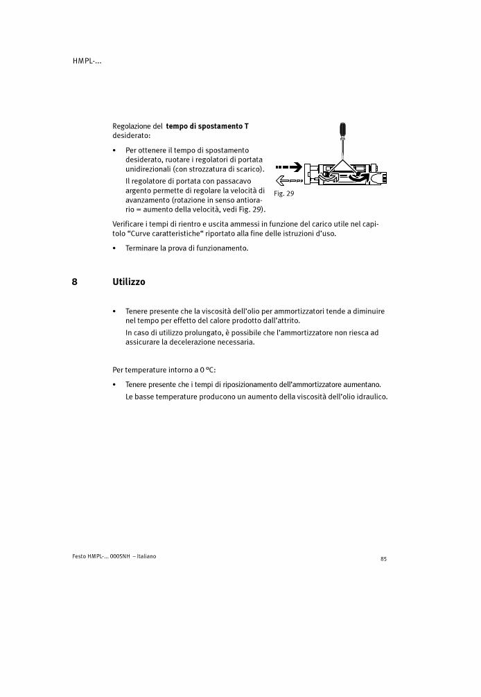
HMPL-...
Festo HMPL-... 0005NH – Italiano 85
Regolazione del tempo di spostamento Tdesiderato:
� Per ottenere il tempo di spostamentodesiderato, ruotare i regolatori di portataunidirezionali (con strozzatura di scarico).
Il regolatore di portata con passacavoargento permette di regolare la velocità diavanzamento (rotazione in senso antiora-rio = aumento della velocità, vedi Fig. 29).
Verificare i tempi di rientro e uscita ammessi in funzione del carico utile nel capi-tolo “Curve caratteristiche“ riportato alla fine delle istruzioni d’uso.
� Terminare la prova di funzionamento.
8 Utilizzo
� Tenere presente che la viscosità dell’olio per ammortizzatori tende a diminuirenel tempo per effetto del calore prodotto dall’attrito.
In caso di utilizzo prolungato, è possibile che l’ammortizzatore non riesca adassicurare la decelerazione necessaria.
Per temperature intorno a 0 °C:
� Tenere presente che i tempi di riposizionamento dell’ammortizzatore aumentano.
Le basse temperature producono un aumento della viscosità dell’olio idraulico.
Fig. 29

HMPL-...
Festo HMPL-... 0005NH – Italiano86
� Accertarsi che gli elementi di ammortizzazione non presentino i seguenti segnidi usura:
Elemento diammortizzazione
Ammortizzatore4444 Elemento elastico aaaaDDDD
Ciclo di controllo Ogni 2 milioni di corse Ogni 2 milioni di corse
Segni di usura Perdita d’olio; urto violento;l’astina di fermo (15) restabloccata nella posizione di finecorsa di ritorno/esce lenta-mente
Forti rumori
Ciclo di sostituzione Ogni 10 milioni di corse Ogni 5 milioni di corse
Fig. 30
La massa in movimento deve raggiungere le posizioni di fine corsa con la do-vuta forza, senza produrre tuttavia un impatto violento.
� Verificare l’opportunità di aumentare la frequenza dei controlli. Ciò può esserenecessario in presenza di:
– temperature elevate– notevole imbrattamento– liquidi o vapori ad azione sgrassante a distanza ravvicinata.
9 Cura e manutenzione
� In presenza di impurità, pulire il modulo HMPL-... utilizzando un pannomorbido.
Per la pulizia è consentito l’uso di:
– acqua saponata (max. + 60 °C)– detergenti non aggressivi.
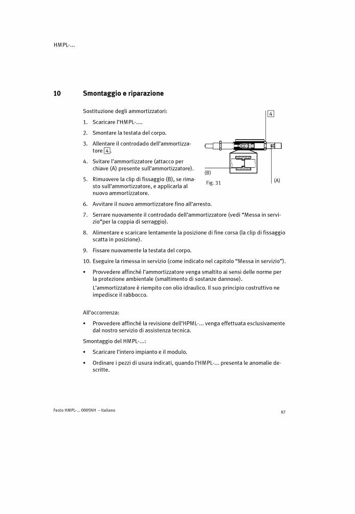
HMPL-...
Festo HMPL-... 0005NH – Italiano 87
10 Smontaggio e riparazione
Sostituzione degli ammortizzatori:
1. Scaricare l’HMPL-....
2. Smontare la testata del corpo.
3. Allentare il controdado dell’ammortizza-tore4.
4. Svitare l’ammortizzatore (attacco perchiave (A) presente sull’ammortizzatore).
5. Rimuovere la clip di fissaggio (B), se rima-sto sull’ammortizzatore, e applicarla alnuovo ammortizzatore.
6. Avvitare il nuovo ammortizzatore fino all’arresto.
7. Serrare nuovamente il controdado dell’ammortizzatore (vedi “Messa in servi-zio“per la coppia di serraggio).
8. Alimentare e scaricare lentamente la posizione di fine corsa (la clip di fissaggioscatta in posizione).
9. Fissare nuovamente la testata del corpo.
10. Eseguire la rimessa in servizio (come indicato nel capitolo “Messa in servizio”).
� Provvedere affinché l’ammortizzatore venga smaltito ai sensi delle norme perla protezione ambientale (smaltimento di sostanze dannose).
L’ammortizzatore è riempito con olio idraulico. Il suo principio costruttivo neimpedisce il rabbocco.
All’occorrenza:
� Provvedere affinché la revisione dell’HPML-... venga effettuata esclusivamentedal nostro servizio di assistenza tecnica.
Smontaggio del HMPL-...:
� Scaricare l’intero impianto e il modulo.
� Ordinare i pezzi di usura indicati, quando l’HMPL-... presenta le anomalie de-scritte.
Fig. 31
4
(A)
(B)

HMPL-...
Festo HMPL-... 0005NH – Italiano88
11 Accessori
Sigla Tipo
Squadretta di montaggio HMZAS-...
Elementi di fissaggio HMSV-.../HMB..-...
Kit di adattatori HAPG-...
Raccordi HMSV-...
Bussole di centratura ZBH-...
Perno di arresto HMPL-...
Elemento di bloccaggio HMPL-...
Valvola di inserimento HEL-...
Finecorsa magnetico SME-8-... /SMT-8-...-B
Targhette di identificazione SBS-8 x 10
Ammortizzatore YSRW-...
Grasso lubrificante ”ESSO BEACON 2”
Fig. 32

HMPL-...
Festo HMPL-... 0005NH – Italiano 89
12 Eliminazione dei guasti
Guasto Possibile causa Rimedio
Movimento irrego-lare del modulolineare
Regolatore di portata unidi-rezionale inserito in manieraerrata
Strozzare la luce dello scarico(predisposizione di fabbrica)
Urto violento nellai i t i l
Ammortizzatori guasti Sostituire gli ammortizzatoriposizione terminale
Modulo lineare sovraccarico Ridurre la velocità
Urto rumorosonella posizioneterminale
Elemento elastico usurato Sostituire l’elemento elastico(solo per HMPL-16/20-...)
Anomalie nel rileva-mento delle posi-i i
Posizione errata dei fine-corsa magnetici
Correggere la posizione deifinecorsa magnetici
zioniTipo errato di finecorsamagnetico impiegato
Impiegare esclusivamentefinecorsa magnetici di tipo SME/SMT-8-...-B
Finecorsa magnetico guasto Sostituire il finecorsa magnetico
Presenza di elementiferritici vicino al finecorsamagnetico
Utilizzare materiali in materialeantimagnetico
Forte perdita HMPL-... soggetto asollecitazioni meccaniche
Fissare HMPL-... su una superficiepiana
Guarnizioni usurate Sostituire le parti d’usura– utilizzando il kit ricambi in
dotazione– inviando il dispositivo a Festo
per la riparazione
Velocità dell’HMPL i f i
Regolatori di portata chiusi Ruotare i regolatori di portataHMPL-... inferioreai parametriprevisti
Portata d’aria insufficiente Installare attacchi di sezionemaggiore, regolare la portata.
previsti
Pressione insufficiente Alimentare l’HMPL-... con min. 4 bar
Forte attrito o forza antago-nista elevata
Scegliere un modulo lineare piùgrande
Fig. 33
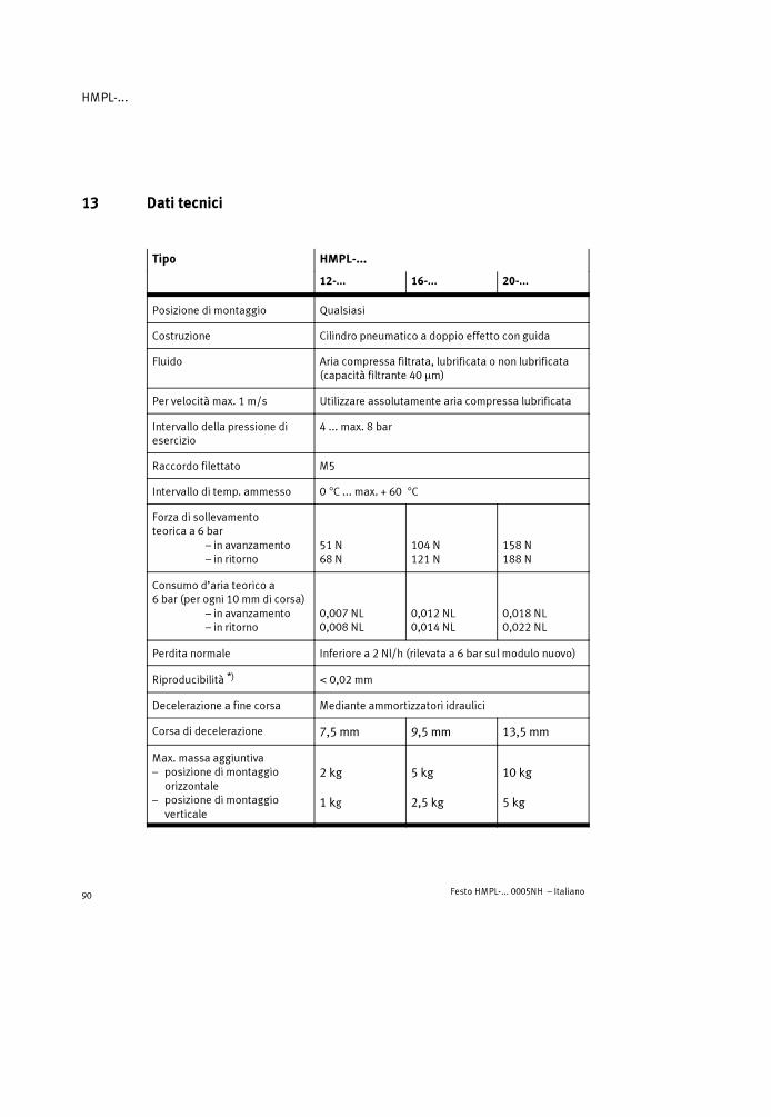
HMPL-...
Festo HMPL-... 0005NH – Italiano90
13 Dati tecnici
Tipo HMPL-...
12-... 16-... 20-...
Posizione di montaggio Qualsiasi
Costruzione Cilindro pneumatico a doppio effetto con guida
Fluido Aria compressa filtrata, lubrificata o non lubrificata(capacità filtrante 40 �m)
Per velocitàmax. 1 m/s Utilizzare assolutamente aria compressa lubrificata
Intervallo della pressione diesercizio
4 ... max. 8 bar
Raccordo filettato M5
Intervallo di temp. ammesso 0 �C ... max. + 60 �C
Forza di sollevamentoteorica a 6 bar
– in avanzamento– in ritorno
51 N68 N
104 N121 N
158 N188 N
Consumo d’aria teorico a6 bar (per ogni 10 mm di corsa)
– in avanzamento– in ritorno
0,007 NL0,008 NL
0,012 NL0,014 NL
0,018 NL0,022 NL
Perdita normale Inferiore a 2 Nl/h (rilevata a 6 bar sul modulo nuovo)
Riproducibilità *)� 0,02 mm
Decelerazione a fine corsa Mediante ammortizzatori idraulici
Corsa di decelerazione 7,5 mm 9,5 mm 13,5 mm
Max. massa aggiuntiva– posizione di montaggio
orizzontale– posizione di montaggio
verticale
2 kg
1 kg
5 kg
2,5 kg
10 kg
5 kg

HMPL-...
Festo HMPL-... 0005NH – Italiano 91
Tipo
20-...16-...12-...
Forza assiale FL **) ammessa(posizione di montaggioverticale)
25 N 40 N 75 N
Coppia di ribaltamento statica(Mx = My) ammessa sullo stelodell’HMPL-... **)
0,7 Nm 1,5 Nm 2,5 Nm
Materiali Profilo del cilindro, piastra frontale,coperchio, testata anteriore, profiloelemento d’arresto: AlViti, stelo: AcciaioPerno; asta di guida: Acciaio (temprato)Raschiapolvere: P5010Adesivi: LoctitePistone, O-Ring, guarnizioni: NBR/PUTappo di chiusura: PA 6Finestrella: PC
Peso appr. ***)
– corsa = 0 mm– per ogni 10 mm di corsa
0,5 kg0,04 kg
0,7 kg0,05 kg
1 kg0,07 kg
*) Su 100 corse consecutive a condizioni di esercizio costanti**) Per il sistema di riferimento si vedi il Capitolo “Montaggio della parte meccanica”***)La massa non aumenta linearmente con la corsa
14 Curve caratteristiche (alla fine delle istruzioni d’uso)

HMPL-...
Festo HMPL-... 0005NH – Italiano92

HMPL-...
Festo HMPL-... 0005NH – Svenska 93
Pneumatisk linjärmodul typ HMPL-...Svenska
1 Komponenter och anslutningar
1 2 3 4 5 6 7 8 9
aJ
aA
aB
aCaDaEaFaG
1 Gängade hål med centreringsförsänkning för montering av den linjärmodulen
2 Förbindingsplatta (tillbehör)
3 Tryckluftsanslutning med strypventil för avluftning
4 Stötdämpare för ändlägesdämpning
5 Anslagselement för inställning av ändläget (säkras med låsmutter)Internt monteringsläge för HMPL-...-AIExternt monteringsläge för HMPL-...-AE
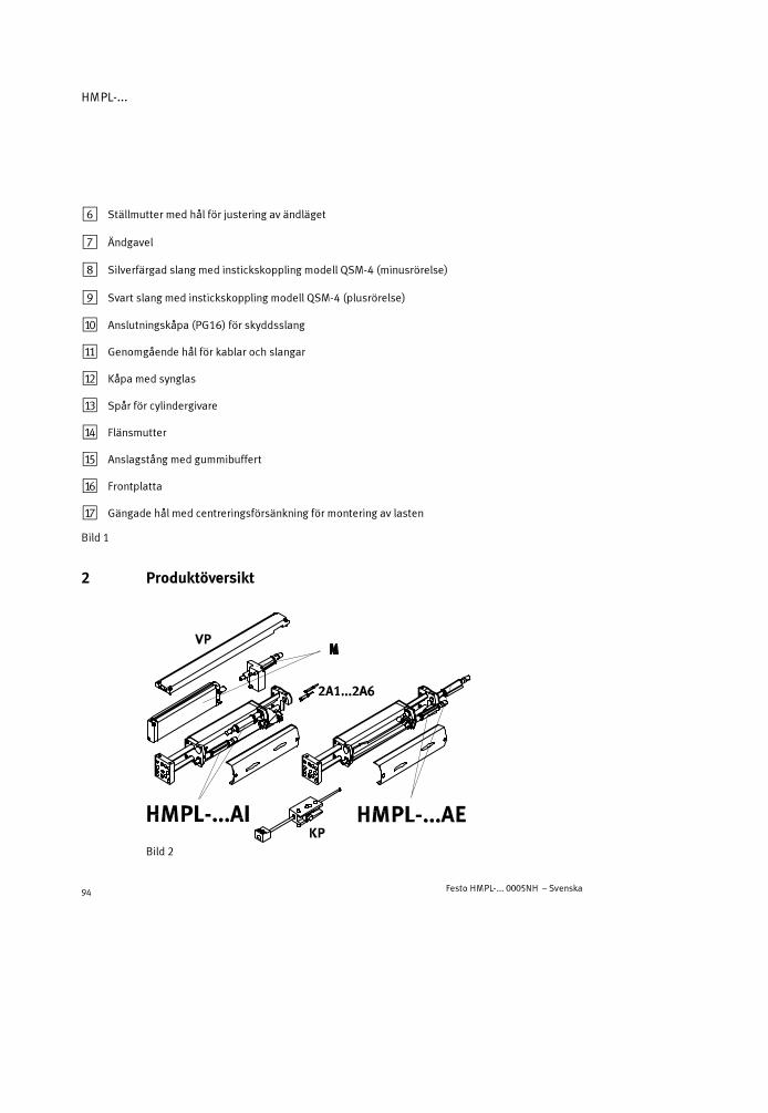
HMPL-...
Festo HMPL-... 0005NH – Svenska94
6 Ställmutter med hål för justering av ändläget
7 Ändgavel
8 Silverfärgad slang med instickskoppling modell QSM-4 (minusrörelse)
9 Svart slang med instickskoppling modell QSM-4 (plusrörelse)
aJ Anslutningskåpa (PG16) för skyddsslang
aA Genomgående hål för kablar och slangar
aB Kåpa med synglas
aC Spår för cylindergivare
aD Flänsmutter
aE Anslagstång med gummibuffert
aF Frontplatta
aG Gängade hål med centreringsförsänkning för montering av lasten
Bild 1
2 Produktöversikt
Bild 2

HMPL-...
Festo HMPL-... 0005NH – Svenska 95
3 Funktion och användning
Med hjälp av växelvis avluftning av trycklufts-anslutningarna8 och9 rör sig kolven pålinjäramodulen HMPL-... fram och tillbaka.Rörelsen överförs till ändgaveln7. Ändga-veln är förbunden med frontplattan aF genomtvå gejderstänger. Hastigheten ställs in medtvå strypbackventiler.
Lasten bromsas och stoppas i ändläget avhydrauliska stötdämpare4. Ändlägenasposition ställs in genom att vrida anslagsele-menten5 ut eller in. Ändlägena kan indike-ras av med hjälp av induktiva givare i spårenaC. Med monterad kåpa kan de induktivagivarnas kopplingsläge avläsas genom syng-lastet aB.
Linjärmodulen HMPL-... är avsedd för hanteringsapplikationer.
4 Transport och lagring
� Ta hänsyn till vikten på HMPL-...:
Den väger upp till 3,2 kg.
Bild 3 8 9
Bild 445
Bild 5

HMPL-...
Festo HMPL-... 0005NH – Svenska96
5 Förutsättningar för att använda produkten
ObsDet kan uppstå felaktiga funktioner vid felaktigt handhavande.
� Följ nedanstående anvisningar för korrekt och säker drift med produkten.
� Jämför de angivna gränsvärdena med din applikation.
De tillåtna värdena för t ex tryck, krafter, moment, massor, hastigheter ochtemperaturer får inte överskridas.
� Använd endast korrekt behandladtryckluft.
� Ta hänsyn till rådande miljövillkor.
� Följ gällande lagar och förordningar.
� Avlägsna emballaget.
Emballagematerialet skall återvinnas.(Undantag: oljat papper = skall destrue-ras).
� Använd det en gång valda mediet underproduktens hela livstid.
Exempel: använd alltid ej dimsmord tryck-luft.
Bild 6
LF-... LR-...
Bild 7
Bild 8

HMPL-...
Festo HMPL-... 0005NH – Svenska 97
� Pålufta hela anläggningen långsamt.
Detta görs med hjälp av en säker-hets-/mjukstartsventil typ HEL-... .Då uppstår inga okontrollerade rörelser.
� Använd produkten i originalskick utannågra som helst egenmäktiga föränd-ringar.
6 Montering
Mekanisk montering
� Hantera HMPL-... så att det inte uppstårskador på gejderstängerna.
Skador leder till minskad driftsäkerhetoch livslängd.
� Montera enheten så att inga spänningaruppstår.
� Placera linjärmodulen så att komponent-erna är åtkomliga.
� Välj ett av följande monteringsalternativ:a) På basytan
(föredraget monteringssätt)b)På sidytan (använd förbindingsplatta2 enligt ’Tillbehör’).
ObsVid sidomontage enligt ill. 12b förstör för djupt iskruvade fästskruvar styrstäng-erna på HMPL-... .
� Observera de följande maximalt tillåtna iskruvningsdjupen för fästskruvarna ifästhålen på HMPL-12/16-... .Vid montering på en basyta enligt ill. 12a begränsar begränsar det gängadehålets bottenlängd fästskruvens gänglängd.
Bild 9
Bild 10
Bild 11
Bild 12
a) b)
2
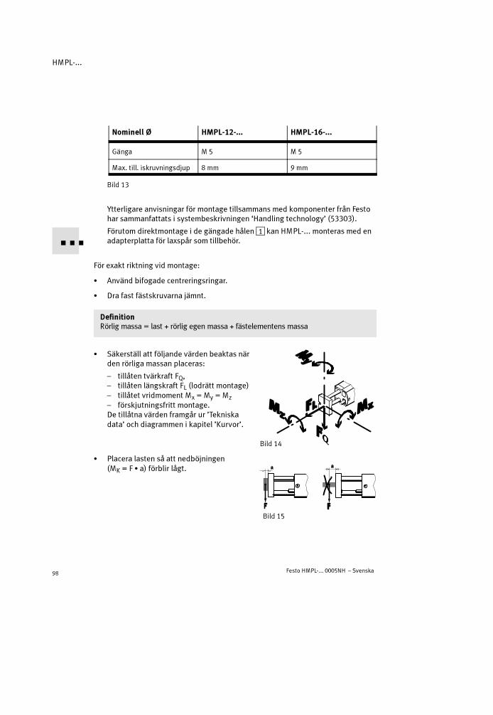
HMPL-...
Festo HMPL-... 0005NH – Svenska98
Nominell Ø HMPL-12-... HMPL-16-...
Gänga M 5 M 5
Max. till. iskruvningsdjup 8 mm 9 mm
Bild 13
Ytterligare anvisningar för montage tillsammans med komponenter från Festohar sammanfattats i systembeskrivningen ‘Handling technology’ (53303).
Förutom direktmontage i de gängade hålen1 kan HMPL-... monteras med enadapterplatta för laxspår som tillbehör.
För exakt riktning vid montage:
� Använd bifogade centreringsringar.
� Dra fast fästskruvarna jämnt.
DefinitionRörlig massa = last + rörlig egen massa + fästelementens massa
� Säkerställ att följande värden beaktas närden rörliga massan placeras:
– tillåten tvärkraft FQ,– tillåten längskraft FL (lodrätt montage)– tillåtet vridmoment Mx = My = Mz
– förskjutningsfritt montage.De tillåtna värden framgår ur ’Tekniskadata’ och diagrammen i kapitel ’Kurvor’.
� Placera lasten så att nedböjningen(MK = F � a) förblir lågt.
Bild 14
Bild 15

HMPL-...
Festo HMPL-... 0005NH – Svenska 99
� Fäst lasten på frontplattan så att lastenstyngdpunkt ommöjligt ligger mellan gej-derstängerna.
Pneumatisk montering
� Se till att tryckluftsanlutningarna harstryp- backventiler.
� Använd en 5/2-vägsventil (påluftatgrundläge) för att styra HMPL-... .
� Anslut slangarna enligt följande(se Bild 17):
– A (plusrörelse, svart slanganslutningQSM-4)
– E (minusrörelse, silverfärgad slangan-slutning QSM-4)
– Pneumatisk anslutning av klämenhe-ten (endast på linjärmodul med kläm-enhet HMPL-....-KP; se separat anvis-ning).
Elektrisk montering
Vid användning av givare:
� Fullfölj montaget enligt följande:
1. Tag loss kåpan och för de induktivagivarna inåt via hålen aA (endastHMPL-...-AI).
2. Den induktiva givaren
– placeras i spåret aC vid anslags-elementet (se Bild 19) och
– justeras och fixeras i ändlägespositio-nerna på HMPL-....
3. Sätt fast kåpan igen.
Bild 16
Bild 17
Bild 18
aA
Bild 19
aC

HMPL-...
Festo HMPL-... 0005NH – Svenska100
7 Idrifttagning
VarningHastigt frisläppta tryckkrafter kan orsakaskador.
� Se till att följande är säkerställt inomrörelseområdet för HMPL-...
– ingen kan ha handen i vägen för demrörliga massan (t ex genom ettskyddsgaller)
– att det inte finns några främmandeföremål.
ObsNär stötdämparna är lossade reduceras deras dämpande verkan avsevärt.
� Säkerställ att stötdämparna är helt iskruvade och låsta (leveransskick).
Grovinställning av en Ändlägesposition:
� Utför följande steg:
1. Avlufta HMPL-...
2. Lossa anslagselementets låsmutter meden gaffelnyckel, tills flänsmuttern aD kanvridas.
3. Grovinställ flänsmuttern i önskad posi-tion. Spåret för den induktiva givaren fårinte skjutas under strypventilen.Följande maximala ändlägen är tillåtna påanslagselementet:
– Helt iskruvad i botten (leveransskick)– Anslagselementets gänga sticker ut
med maximal längd X (se Bild 23).
Bild 20
Bild 21
Bild 22
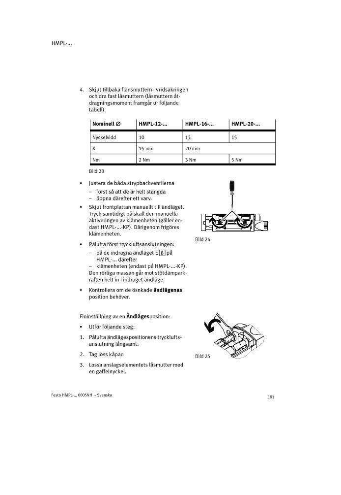
HMPL-...
Festo HMPL-... 0005NH – Svenska 101
4. Skjut tillbaka flänsmuttern i vridsäkringenoch dra fast låsmuttern (låsmuttern åt-dragningsmoment framgår ur följandetabell).
Nominell���� HMPL-12-... HMPL-16-... HMPL-20-...
Nyckelvidd 10 13 15
X 15 mm 20 mm
Nm 2 Nm 3 Nm 5 Nm
Bild 23
� Justera de båda strypbackventilerna
– först så att de är helt stängda– öppna därefter ett varv.
� Skjut frontplattan manuellt till ändläget.Tryck samtidigt på skall den manuellaaktiveringen av klämenheten (gäller en-dast HMPL-...-KP). Därigenom frigöresklämenheten.
� Pålufta först tryckluftsanslutningen:
– på de indragna ändläget E8 påHMPL-... därefter
– klämenheten (endast på HMPL-...-KP).Den rörliga massan går mot stötdämpark-raften helt in i indraget ändläge.
� Kontrollera om de ösnkade ändlägenasposition behöver.
Fininställning av en Ändlägesposition:
� Utför följande steg:
1. Pålufta ändlägespositionens trycklufts-anslutning långsamt.
2. Tag loss kåpan
3. Lossa anslagselementets låsmutter meden gaffelnyckel.
Bild 24
Bild 25

HMPL-...
Festo HMPL-... 0005NH – Svenska102
4. Vrid ställmuttern med hål med en slag-dorn/gaffelnyckel tills den rörliga mas-sans ändlägesposition har nåtts. Obser-vera anslagselementets maximalaändlägen (se ‘Grovinställning’).
Ett varv motsvarar ca. 1 mm förändring avslaget.
5. Håll emot ställmuttern med hål med enslagdorn/gaffelnyckel och vrid samtidigtfast låsmuttern (låsmutterns åtdragnings-moment framgår ur nedanstående tabell).
Nominell ���� HMPL-12-... HMPL-16-... HMPL-20-...
Hål i ställmuttern 2 mm 2,4 mm 2,4 mm
Nyckelvidd 10 13 15
Nm 2 Nm 3 Nm 5 Nm
Bild 28
6. Upprepa ovanstående punkter 1 till 5 för inställning av ändlägespositionen påmotsatta sidan.
7. Vrid den induktiva givaren något inåt. I annat fall kan inte kåpan sättas fast.
8. Sätt fast kåpan igen.
Starta en provkörning enligt följande:
� Kontrollera under provkörningen med låg taktfrekvens om förflyttningstiden Tpå HMPL skall ändras.
Den rörliga massan skall nå ändläget utan problem, men inte gå emot hårt.
Bild 26
Bild 27

HMPL-...
Festo HMPL-... 0005NH – Svenska 103
Inställning av önskad förflyttningstid T:
� Justera upp strypbackventilen (avluft-strypt) tills önskad förflyttningstid harnåtts.
Strypventilen med den silverfärgadeslangen-är avsedd för inställning av plus-rörelsen (vridning moturs = ökning avhastigheten; se Bild 29).
Den tillåtna in-/utmatningstiden i förhållande till lasten framgår ur diagrammet ikapitel ’Kurvor’ i bruksanvisningen.
� Avsluta provkörningen.
8 Drift
� Observera att stötdämparoljans viskositet avtar under drift, beroende på attdet uppstår friktionsvärme.
Detta gör att stötdämparna kan slå igenom vid längre drifttid.
Bild 29
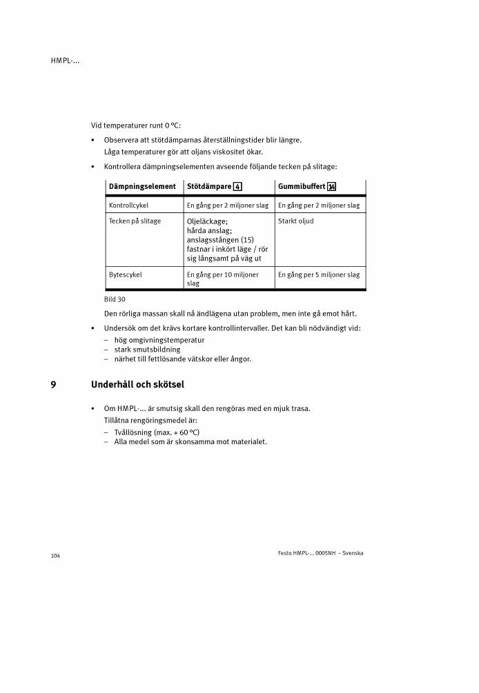
HMPL-...
Festo HMPL-... 0005NH – Svenska104
Vid temperaturer runt 0 °C:
� Observera att stötdämparnas återställningstider blir längre.
Låga temperaturer gör att oljans viskositet ökar.
� Kontrollera dämpningselementen avseende följande tecken på slitage:
Dämpningselement Stötdämpare4444 Gummibuffert aaaaDDDD
Kontrollcykel En gång per 2 miljoner slag En gång per 2 miljoner slag
Tecken på slitage Oljeläckage;hårda anslag;anslagsstången (15)fastnar i inkört läge / rörsig långsamt på väg ut
Starkt oljud
Bytescykel En gång per 10 miljonerslag
En gång per 5 miljoner slag
Bild 30
Den rörliga massan skall nå ändlägena utan problem, men inte gå emot hårt.
� Undersök om det krävs kortare kontrollintervaller. Det kan bli nödvändigt vid:
– hög omgivningstemperatur– stark smutsbildning– närhet till fettlösande vätskor eller ångor.
9 Underhåll och skötsel
� Om HMPL-... är smutsig skall den rengöras med en mjuk trasa.
Tillåtna rengöringsmedel är:
– Tvållösning (max. + 60 °C)– Alla medel som är skonsammamot materialet.

HMPL-...
Festo HMPL-... 0005NH – Svenska 105
10 Demontering och reparation
Byte av stötdämpare:
1. Avlufta HMPL-...
2. Tag loss kåpan
3. Lossa låsmuttern på stötdämparen4.
4. Skruva ut stötdämparen (nyckelfäste (A)finns på stötdämparen).
5. Dra av förbindelseklämman (B), om denhar blivit kvar på stötdämparen och tryckfast den på den nya stötdämparen.
6. Skruva i stötdämparen till anslaget.
7. Dra fast låsmuttern på stötdämparen (åtdragningsmoment se kapitel ’Idrifttag-ning’).
8. Pålufta och avlufta ändlägespositionen försiktigt (förbindelseklämman låser).
9. Sätt fast kåpan igen.
10. Genomför en återstart (enligt kapitel ’Idrifttagning’).
� Se till att stötdämparen återvinns på ett miljöriktigt sätt (konvertering av ris-kavfall).
Stötdämparen är fylld med hydraulolja. Dess konstruktionsprincip gör att detinte går att fylla på olja.
Vid behov:
� Se till att översyn HMPL-... endast utförs av Festo reparationsservice.
Urmontering av HMPL-...:
� Pålufta hela anläggningen och enheten.
� Beställ de angivna förbrukningsdelarna om HMPL-... visar angivna tecken påslitage.
Bild 31
4
(A)
(B)

HMPL-...
Festo HMPL-... 0005NH – Svenska106
11 Tillbehör
Beteckning Typ
Fästvinklar HMZAS-...
Fästanordningar HMSV-.../HMB..-...
Adapterbyggsats HAPG-...
Förbindelseelement HMSV-...
Centreringshylsor ZBH-...
Anslagsbultar HMPL-...
Klämenhet HMPL-...
Mjukstartventil HEL-...
Induktiv givare SME-8-... /SMT-8-...-B
Märkskyltar SBS-8 x 10
Stötdämpare YSRW-...
Smörjfett ’ESSO BEACON 2’
Bild 32

HMPL-...
Festo HMPL-... 0005NH – Svenska 107
12 Åtgärd vid störning
Störning Möjlig orsak Åtgärd
Den linjära modulenrör sig ojämnt
Strypbackventilen felaktigtmonterad
Försök att strypa avluften(leveransskick)
Hårt anslag i slagetsä dläg
Stötdämparen defekt Byt stötdämpareändläge
Linjärmodulen överbelastad Reducera hastigheten
Högljutt anslag islagets ändläge
Gummibufferterna slitna Byt gummibuffertar (endast påHMPL-16/20-...)
Störningar vidpositionsavlkänning
De induktiva givarnasposition felaktig
Korrigera de induktiva givarnasposition
Fel typ av induktiv givaremonterad
Använd endast induktiva givaretyp SME/SMT-8-...-B
Defekt induktiv givare Byt induktiv givare
Ferritiska delar i närhetenav den indsuktiva givaren
Använd delar av ej magnetiskamaterial
Starkt läckage Spänningar vid montageav HMPL-...
Montera HMPL-... på ett jämntunderlag
Slitna tätningar Byt förslitningsdelar– själv med en sats förslitnings-
delar– kontakta Festo för reparation
HMPL-... når inteö k d h tigh t
Strypventilerna stängda Justera strypventilernaönskad hastighet
Luftvolym saknas Öka anslutningsareorna, ansluten volym
För lågt tryck Trycksätt HMPL-... med min. 4 bar
Hög friktion eller motkraft Välj en större linjärmodul
Bild 33

HMPL-...
Festo HMPL-... 0005NH – Svenska108
13 Tekniska data
Typ HMPL-...
12-... 16-... 20-...
Monteringsläge Valfritt
Konstruktion Dubbelverkande pneumatisk cylinder med gejderstänger
Medium Filtrerad tryckluft dimsmord eller ej dimsmord (filterfinhet40 �m)
Vid hastigheter över 1 m/s Använd alltid dimsmord tryckluft
Driftttryckområde Minst 4 ... max. 8 bar
Anslutningsgänga M5
Tillåtet temperaturområde 0 �C ... max + 60 �C
Teoretisk effektiv kraft vid6 bar – plusrörelse
–minussrörelse51 N68 N
104 N121 N
158 N188 N
Teoretisk luftförbrukningvid 6 bar (per 10 mm slag)
– plusrörelse–minussrörelse
0,007 NL0,008 NL
0,012 NL0,014 NL
0,018 NL0,022 NL
Normalt läckage Mindre än 2 Nl/h (i nyskick, uppmätt vid 6 bar)
Repeternoggrannhet *) � 0,02 mm
Ändlägesdämpning Hydraulisk dämpning
Dämpningsläge 7,5 mm 9,5 mm 13,5 mm
Max. tilläggsmassa– horisontellt montage– vertikalt montage
2 kg1 kg
5 kg2,5 kg
10 kg5 kg
Tillåten längskraft FL **)
(lodrätt montage)25 N 40 N 75 N

HMPL-...
Festo HMPL-... 0005NH – Svenska 109
Typ
20-...16-...12-...
Max. tillåtetvridmoment(Mx = My) på gejderstäng-erna på HMPL-... **)
0,7 Nm 1,5 Nm 2,5 Nm
Material Cylinderprofil, frontplattaändgavel, framgavel,anslagselementprofil: AlSkruvar, kolvstång: StålBultar, gejderstänger: Stål (härdat)Avstrykare: P 5010Lim: LoctiteKolvar, O-ringar, packningar: NBR/PUPluggar: PA 6Synglas: PC
Ca.-vikt***)
– slag = 0 mm– per 10 mm slag
0,5 kg0,04 kg
0,7 kg0,05 kg
1 kg0,07 kg
*) Under 100 på varandra följande slag vid konstanta driftvillkor**) Referenssystem se kapitel ’Mekanisk montering’***)Massan ökar inte linjärt med slaget
14 Kurvor (i slutet av bruksanvisningen)

HMPL-...
Festo HMPL-... 0005NH – Svenska110

HMPL-...
Festo HMPL-... 0005NH 111
14 KennlinienCharacteristic curvesCurvas característicasCourbes caractéristiquesCurve caratteristicheKurvor
a) Max. zulässige Querkraft FQ [N] in Abhängigkeit der Hublänge h [mm]
a) Max. permitted transverse force FQ [N] as a factor of the stroke length h [mm]
a) Fuerza transversal máxima permitida FQ [N] en función de la carrera h [mm]
a) Force transversale max. admissible FQ [N] en fonction de la course h [mm]
a) Max. forza trasversale amm. FQ [N] in funzione della lunghezza della corsa h [mm]
a) Max till. tvärkraft FQ [N] beroende på slaglängd h [mm]
Q

HMPL-...
Festo HMPL-... 0005NH112
b) Max. zul. dynamisches DrehmomentM [Nm] (Mz = My =Mx) in Abhängigkeitder Hublänge h [mm]
b) Max. permitted dynamic torqueM [Nm] (Mz = My =Mx) as a factor of thestroke length h [mm]
b) Par dinámico máximo transmitidoM [Nm] (Mz = My =Mx) en función de lacarrera h [mm]
b) Couple dynamique max. admissibleM [Nm] (Mz = My =Mx) en fonction de lacourse h [mm]
b) Max. valore di coppia dinamica amm.M [Nm] (Mz = My =Mx) in funzione dellalunghezza della corsa h [mm]
b) Max till. dynamiskt vridmomentM [Nm] (Mz = My =Mx) beroende på slaglängd h [mm]

HMPL-...
Festo HMPL-... 0005NH 113
c) Zul. Ein-/Ausfahrzeit t [ms] in Abhängigkeit der Nutzlastm [kg] beihorizontaler Einbaulage (bei geringerem Hub siehe Katalogangaben)
c) Permitted retracting/extending time t [ms] as a factor of the work loadm [kg]in horizontal fitting position (at lower stroke see catalogue specifications)
c) Tiempo de avance/retroceso permitido t [ms] en función de la carga de trabajom [kg] en posición de montaje horizontal (para carreras inferiores ver especifi-caciones del catálogo)
c) Temps d’entrée/sortie admissible t [ms] en fonction de la charge utilem [kg]en cas de position de montage horizontale (en cas de faible course, voir lesindications du catalogue)
c) Tempo di rientro/uscita amm. t [ms] in funzione del carico utilem [kg] per posi-zione di montaggio orizzontale (per corse brevi vedi indicazioni nel catalogo)
c) Till. in-/utkörningstid t [ms] beroende på nyttig lastm [kg] vid horisontelltmontageläge (vid mindre slag se kataloguppgifter)

HMPL-...
Festo HMPL-... 0005NH114
d) Zul. Ein-Ausfahrzeit t [ms] in Abhängigkeit der Nutzlastm [kg] bei vertikalerEinbaulage (bei geringerem Hub siehe Katalogangaben)
d) Permitted retracting/extending time t [ms] as a factor of the work loadm [kg]in vertical fitting position (at lower stroke see catalogue specifications)
d) Tiempo de avance/retroceso permitido t [ms] en función de la carga de trabajom [kg] en posición de montaje vertical (para carreras inferiores ver especifi-caciones del catálogo)
d) Temps d’entrée/sortie admissible t [ms] en fonction de la charge utilem [kg]en cas de position de montage verticale (en cas de faible course, voir lesindications du catalogue)
d) Tempo di rientro/uscita amm. t [ms] in funzione del carico utilem [kg] per posi-zione di montaggio verticale (per corse brevi vedi indicazioni nel catalogo)
d) Till. in-/utkörningstid t [ms] beroende på nyttig lastm [kg] vid vertikaltmontageläge (vid mindre slag se kataloguppgifter)

HMPL-...
Festo HMPL-... 0005NH 115

HMPL-...
Festo HMPL-... 0005NH116
Weitergabe sowie Vervielfältigung dieses Dokuments,Verwertung und Mitteilung seines Inhalts verboten,soweit nicht ausdrücklich gestattet. Zuwiderhandlungenverpflichten zu Schadenersatz. Alle Rechte für den Fall derPatent-, Gebrauchsmuster- oder Geschmacksmuster-eintragung vorbehalten.
The reproduction, distribution and utilization of thisdocument as well as the comunication of its contents toothers without express authorization is prohibited.Offenders will be held liable for the payment of damages.All rights reserved in the event of the grant of a patent,utility module or design.
Sin nuestra expresa autorización, queda terminantementeprohibida la reproducción total o parcial de este documento,así como su uso indebido y/o exhibición o comunicación aterceros. De los infractores se exigirá el correspondienteresarcimiento de daños y perjuicios. Quedan reservadostodos los derechos inherentes, en especial los de patentes,de modelos registrados y estéticos.
Toute communication ou reproduction de ce document, sousquelque form que se soit, et toute exploitation ou communi-cation de son contenu sont interdites, sauf autorisationécrite expresse. Tout manquement à cet règle est illicite etexpose son auteur au versement de dommages et intérêts.Touts droits réservés pour le cas de la délivrance d’un bre-vet d’un modèle d’utilité ou d’un modèle de présentation.
Copyright:� Festo AG & Co.,Postfach 6040D-73726 Esslingen
Phone:49 / 711 / 347 0È vietato consegnare a terzi o riprodurre questo documento,
utilizzarne il contenuto o renderlo comunque noto a terzisenza esplicita autorizzazione. Ogni infrazione comporta ilriscarimento dei danni subiti. Sono riservati tutti i dirittiderivanti dalla concessione di brevetti per invenzioniindustriali di utilità o di brevetti per modelli ornamentali.
+49 / 711 / 347-0
Fax:+49/ 711 / 347-2144
e-mail:[email protected]
Detta dokument får inte utan vårt tillstånd utlämnas tillobehöriga eller kopieras, ej heller får dess innehåll delgesobehöriga eller utnyttjas. Överträdelse medför skade-ståndskrav. Alla rättigheter förbehålls, särskilt rätten attinlämna patent-, bruksmönster- eller mönsteransökningar.
Internet:http://www.festo.com
Original: de
Version: 0005NH
Related Documents


![[XLS] · Web viewMice "preconditioned" with latrepirdine show a delayed symptom onset and a significant increase in life span. (1 μg/kg, intraperitoneal ).[3] Fruquintinib (HMPL-013)](https://static.cupdf.com/doc/110x72/5ac161e67f8b9a5a4e8d12a0/xls-viewmice-preconditioned-with-latrepirdine-show-a-delayed-symptom-onset-and.jpg)


