Workbook TP 102 With CD-ROM Festo Didactic 541089 EN Pneumatics Advanced level 1V1 0V2 0Z1 2V1 2 2 2 4 4 4 3 3 3 5 5 5 1 1 1 14 14 14 12 12 12 3 1 2B1 2 1V2 2V2 1V3 2V3 1A1 2A1 1B1 2B1 2 1 12 10 1 1 1 1 2 2 2 2 2 3 1 1B1 2 10 2 3 1 0V1 0S1 2 4 3 5 1

Welcome message from author
This document is posted to help you gain knowledge. Please leave a comment to let me know what you think about it! Share it to your friends and learn new things together.
Transcript

Workbook
TP 102
With CD-ROM
Festo Didactic
541089 EN
PneumaticsAdvanced level
1V1
0V2 0Z1
2V1
2
224
4
4
3
3
35
5
51
1
1
14
14
1412 12
12
31
2B1 2
1V2 2V21V3 2V3
1A1 2A11B1 2B1
2
1
12 10
1 11 1
2 22 2
2
31
1B1 2
10
2
31
0V1
0S1 24
351

Use for intended purpose
The training package for pneumatics, advanced level may only be used:
• For its intended purpose in teaching and training applications
• When its safety functions are in flawless condition
The components included in the training package are laid out in accordance with the latest technology, as
well as recognised safety rules. However, life and limb of the user and third parties may be endangered, and
the components may be impaired if they are used improperly.
The training system from Festo Didactic has been developed and manufactured for training and vocational
education in the field of automation technology. The respective training companies and/or trainers must
ensure that all trainees observe the safety precautions which are described in this workbook.
Festo Didactic hereby excludes any and all liability for damages suffered by trainees, the training company
and/or any third parties, which occur during use of the equipment sets in situations which serve any
purpose other than training and/or vocational education, unless such damages have been caused by Festo
Didactic due to malicious intent or gross negligence.
Order number: 541089
Revision level: 01/2010
Authors: W. Haring, M. Metzger, R.-C. Weber
Editor: Frank Ebel
Graphics: Doris Schwarzenberger
Layout: 01/2010
© Festo Didactic GmbH & Co. KG, 73770 Denkendorf, 2010
Internet: www.festo-didactic.com
E-mail: [email protected]
The reproduction, distribution and utilisation of this document, as well as the communication of its contents
to others without explicit authorisation, is prohibited. Violators will be held liable for compensation of
damages. All rights reserved, in particular the right to file patent, utility model and registered design
applications.
© Festo Didactic GmbH & Co. KG 541089 III
Table of contents
Preface _________________________________________________________________________________ V
Introduction ____________________________________________________________________________ VII
Work instructions and safety precautions ____________________________________________________ VIII
Technology package for pneumatics (TP 100) ___________________________________________________X
Learning objectives for the basic level (TP 102) _________________________________________________ XI
Allocation of learning objectives per exercise _________________________________________________ XII
Equipment set for the advanced level (TP 102) ________________________________________________ XIV
Allocation of components per exercise ______________________________________________________ XVII
Tools for the trainer _____________________________________________________________________ XVIII
Structure of the exercises ________________________________________________________________ XVIII
Designations of the components ____________________________________________________________ XIX
CD-ROM contents ________________________________________________________________________ XIX
Equipment set for the basic level (TP 101) ____________________________________________________ XXI
Learning objectives for the advanced level (TP 102) ___________________________________________ XXII
Solutions
Exercise 1: Opening and closing an oven door ___________________________________________________ 1
Exercise 2: Separating beverage bottles________________________________________________________ 7
Exercise 3: Drilling manifold blocks _________________________________________________________ 15
Exercise 4: Filling beverage bottles __________________________________________________________ 23
Exercise 5: Cleaning workpieces ____________________________________________________________ 33
Exercise 6: Printing cell phone housings _____________________________________________________ 43
Exercise 7: Packaging spark plugs __________________________________________________________ 51
Exercise 8: Sealing guide bushes ___________________________________________________________ 59
Exercise 9: Hardening material specimens ____________________________________________________ 67
Exercise 10: Bending sheet metal strips ______________________________________________________ 73
Exercises
Exercise 1: Opening and closing an oven door ___________________________________________________ 1
Exercise 2: Separating beverage bottles________________________________________________________ 7
Exercise 3: Drilling manifold blocks _________________________________________________________ 15
Exercise 4: Filling beverage bottles __________________________________________________________ 23
Exercise 5: Cleaning workpieces ____________________________________________________________ 33
Exercise 6: Printing cell phone housings _____________________________________________________ 43
Exercise 7: Packaging spark plugs __________________________________________________________ 51
Exercise 8: Sealing guide bushes ___________________________________________________________ 59
Exercise 9: Hardening material specimens ____________________________________________________ 67
Exercise 10: Bending sheet metal strips ______________________________________________________ 73

IV © Festo Didactic GmbH & Co. KG 541089

© Festo Didactic GmbH & Co. KG 541089 V
Preface
Festo Didactic’s training system for automation technology is geared towards various educational
backgrounds and vocational requirements. The training system is therefore broken down as follows:
• Technology-oriented training packages
• Mechatronics and factory automation
• Process automation and control technology
• Robotino® – training and research with mobile robots
• Hybrid learning factories
The technology packages deal with various technologies including pneumatics, electro-pneumatics,
hydraulics, electro-hydraulics, proportional hydraulics, programmable logic controllers, sensor technology,
electrical engineering and electric drives.
The modular design of the training system allows for applications which go above and beyond the
limitations of the individual packages, such as, for example, PLC actuation of pneumatic, hydraulic and
electric drives is possible.

VI © Festo Didactic GmbH & Co. KG 541089
All training modules have the same structure:
• Hardware
• Teachware
• Software
• Seminars
The hardware is comprised of industrial components and systems that are specially designed for training
purposes.
The structure of the teachware corresponds to that of the training hardware. It includes:
• Textbooks (with exercises and examples)
• Workbooks (with practical exercises, supplementary instructions and solutions)
• Transparencies and videos (for dynamic instruction)
The teaching and learning media are available in several languages. They’re intended for use in classroom
instruction, but are also suitable for self-study.
Where software is concerned, computer training programs, as well as simulation, visualisation, project
engineering, design engineering and programming software, are made available.
A wide range of seminars offerings covering the contents of the training packages round off the programme
for training and vocational education.
If you have suggestions or feedback about this manual, please send us an e-mail at [email protected].
The authors and Festo Didactic look forward to your feedback.
© Festo Didactic GmbH & Co. KG 541089 VII
Introduction
This workbook is a component part of the Learning System for Automation and Technology of Festo Didactic
GmbH & Co. KG. This system provides a solid basis for practice-oriented vocational and further training.
Technology package TP 100 is comprised exclusively of pneumatic control systems.
Prerequisite for the assembly of control systems is a fixed workstation using a Festo Didactic profile plate. A
mobile, silenced compressor (230 V, maximum 8 bar = 800 kPa) can be used for compressed air supply.
Optimal operational reliability is achieved if the control system is operated on unlubricated air at a working
pressure of p = 5 bar = 500 kPa.
The equipment set of Advanced Level TP 102 is used to construct complete control systems for all of the 10
exercise definitions. The theoretical fundamentals to help you understand this collection of exercises can be
found in the textbook
• Pneumatics – Basic Level
Also available are data sheets in respect individual devices (cylinders, valves, measuring devices, etc.).

VIII © Festo Didactic GmbH & Co. KG 541089
Work instructions and safety precautions
General
• Trainees should only work with the circuits under the supervision of a trainer.
• Observe specifications included in the data sheets for the individual components and in particular all
safety instructions!
• Faults which may impair safety must not be generated in the training environment and must be
eliminated immediately.
Mechanical setup
• Mount all the components securely onto the profile plate.
• Adhere to instructions regarding positioning of the components.
Electrical setup
• Use low voltage only (max. 24 V DC).
• Electrical connections must only be established and interrupted in the absence of voltage!
• Only use connecting cables with safety plugs for electrical connections.
• Only pull the plug when disconnecting connecting cables – never pull the cable.
Pneumatics
• Do not exceed the maximum permissible pressure of 600 kPa (6 bar).
• Do not activate compressed air until all the tubing connections have been completed and secured.
• Do not disconnect tubing while under pressure.
• Danger of injury when switching compressed air on!
Cylinders may advance and retract automatically.
• Danger of accident due to tubing slipping off!
– Use shortest possible tubing connections.
– Wear safety glasses.
– In the event that tubing slips off:
Switch compressed air supply off immediately.
• Pneumatic circuit setup:
Connect the components with plastic tubing with an outside diameter of 4 or 6 mm. Push the tubing
into the push-in connector as far as it will go.
• Switch compressed air supply off before dismantling the circuit.
• Dismantling the pneumatic circuit:
press the blue release ring down, after which the tubing can be pulled out.

© Festo Didactic GmbH & Co. KG 541089 IX
Mounting technology
The mounting boards for the components are equipped with mounting variant A, B or C:
• Variant A, snap-in system
Lightweight components that are not load-bearing (e.g. directional control valves and sensors). Simply
clip the components into the slot on the profile plate. Release the component from the slot by turning
the blue lever.
• Variant B, bolt system
Components with medium load capacity (e.g. pneumatic cylinders). These components are clamped
onto the profile plate using T-head bolts. The blue, knurled nut is used for clamping and loosening.
• Variant C, screw system
For components with high load capacity and components which are seldom removed from the profile
plate (for example on-off valve with filter regulator). The components are secured with socket head
screws and T-head bolts.

X © Festo Didactic GmbH & Co. KG 541089
Technology package for pneumatics (TP 100)
The TP 100 technology package consists of a multitude of training materials and seminars. The subject
matter of this package is pneumatic controllers. The individual components included in the TP 100
technology package can also be included in other modules.
Important elements of the TP 100 package
• Permanent workstation with Festo Didactic profile plate
• Compressor (230 V, 0.55 kW, max. 8 bar = 800 kPa)
• Equipment sets or individual components (e.g. cylinders, directional control valves, preset counters,
stepper modules, logic components, pneumatic proximity switches)
• Optional learning materials (e.g. optical displays, 5/3-way valve, pulling/pushing load)
• Practical training models
• Complete laboratory setups
Training documentation
Textbooks TP 101 basic level
Fundamentals of pneumatic control technology
Maintenance of pneumatic components and systems
Pneumatics/electro-pneumatics
Workbooks TP 101 basic level
TP 102 advanced level
Optional teachware Set of transparencies
Magnetic symbols, drawing template
FluidSIM® Pneumatik simulation software
WBT Pneumatics
Set of cutaway models with storage case
Seminars
P100 Basic pneumatics knowledge for machine operators
P111 Fundamentals of pneumatics and electro-pneumatics
P121 Maintenance and troubleshooting for pneumatic and electro-pneumatic systems
P-OP Tracking down waste – economic use of pneumatics
P-NEU Pneumatics refresher and update
IW-PEP Repair and maintenance in the field of control technology – pneumatic and electro-pneumatic systems
P-AL Pneumatics for vocational education
P-AZUBI Pneumatics and electro-pneumatics for trainees
Please refer to the current seminar schedule for event locations, dates and prices.
You’ll find further training materials in our catalogue and on the Internet. The training system for automation
technology is continuously updated and expanded. Transparency sets, videos, CD-ROMs and DVDs, as well
as textbooks, are offered in several languages.

© Festo Didactic GmbH & Co. KG 541089 XI
Learning objectives for the basic level (TP 102)
• Become familiar with various types of end-position sensing.
• Become familiar with options for setting up controllers with latching functions.
• Be able to convert 3/2 and/or 5/2-way valves (normally closed/normally open).
• Become familiar with displacement-step diagrams and learn to create them for a specific circuit.
• Be able to implement push-pull circuits with parallel motion.
• Be able to use pneumatic subtraction counters.
• Be able to set up indirect actuation of cylinders.
• Be able to select and adjust suitable sensors for an application.
• Become familiar with the setup and function of a stepper module.
• Be able to set up a basic sequence control system with “continuous cycle”.
• Be able to install one-way flow control valves in accordance with specified conditions.
• Be able to implement OR operations for feedback signals.
• Be able to adjust time delay in accordance with requirements.
• Become familiar with circuits in order to interrupt delay times by means of signal inputs.
• Be able to implement the following input commands:
• emergency stop, acknowledge emergency stop, start, reset, stop at end of cycle and automatic/manual.
• Be able to setup a sequence control system with idle step.
• Become familiar with one way of enabling adjustable step repetitions within a motion sequence and be
able to set up the corresponding circuit.
• Be able to develop input circuits with self-latching loop.
• Become familiar with one way or implementing a double stroke for a cylinder and be able to set up the
corresponding circuit.
• Become familiar with circuits which enable reversing cylinder motion within the sub-stroke range.
• Be able to develop an input circuit for a sequence control system with secure pilot air.
• Be able to stop a double-acting cylinder within the sub-stroke range.
• Be able to invert valve ouTP ut signals.
• Be able to implement a controller with command action in combination with sequence control.
XII © Festo Didactic GmbH & Co. KG 541089
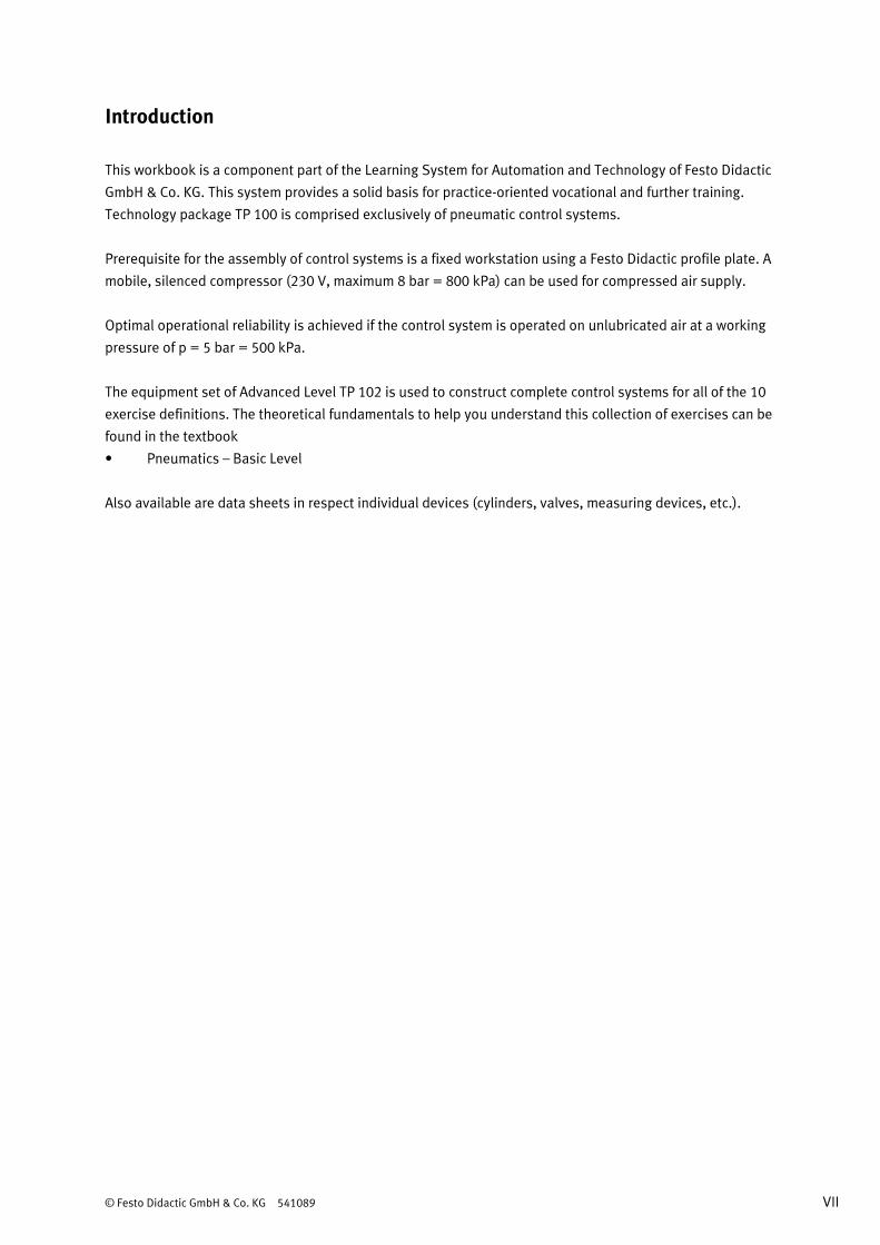
Allocation of learning objectives per exercise
Exercise 1 2 3 4 5 6 7 8 9 10
Learning objectives
Become familiar with various types of end-
position sensing. •
Become familiar with options for setting up
controllers with latching functions. •
Be able to convert 3/2 and/or 5/2-way valves
(normally closed/normally open. •
Become familiar with displacement-step
diagrams and learn to create them for a
specific circuit.
•
Be able to implement push-pull circuits with
parallel motion. •
Be able to use pneumatic subtraction
counters. •
Be able to set up indirect actuation of
cylinders. • •
Be able to select and adjust suitable sensors
for an application. • • • •
Become familiar with the setup and function of
a stepper module. •
Be able to set up a basic sequence control
system with “continuous cycle”. •
Be able to install one-way flow control valves
in accordance with specified conditions. •
Be able to implement OR operations for
feedback signals. •
Be able to adjust time delay in accordance
with requirements. •
Become familiar with circuits in order to
interrupt delay times by means of signal
inputs.
•
Be able to set up a sequence control system
with input commands including
automatic/manual, start and reset.
•

© Festo Didactic GmbH & Co. KG 541089 XIII
Exercise 1 2 3 4 5 6 7 8 9 10
Learning objectives
Be able to develop input circuits with self-
latching loop which allow for the following
inputs: automatic/manual, start, stop at end of
cycle and reset.
•
Be able to set up a sequence control system with
idle step •
Become familiar with one way of enabling
adjustable step repetitions within a motion
sequence and be able to set up the
corresponding circuit.
•
Become familiar with one way of implementing a
double stroke for a cylinder and be able to set up
the corresponding circuit.
•
Become familiar with circuits which enable
reversing cylinder motion within the sub-stroke
range.
•
Be able to develop an input circuit for a
sequence control system with secure pilot air
with the following inputs: start,
automatic/manual and reset.
•
Be able to stop a double-acting cylinder within
the sub-stroke range. •
Be able to invert valve ouTP ut signals. •
Be able to implement a controller with command
action in combination with sequence control. •

XIV © Festo Didactic GmbH & Co. KG 541089
Equipment set for the advanced level (TP 102)
The equipment set for the advanced level has been put together for vocational training in the field of
pneumatic control technology. The two equipment sets (TP 101 and TP 102) include components which are
necessary for mastering the predefined learning objectives, and can be supplemented with other equipment
sets for the training system for automation technology as desired.
Equipment set for the advanced level (TP 102)
Quantity Designation Order no.
1 3/2-way roller lever valve with idle return, normally closed 152867
4 3/2--way pneumatic valve, convertible 539768
2 3/2-way valve with pushbutton actuator, normally closed 152860
1 3/2-way valve with mushroom actuator, normally open (emergency stop) 152864
2 5/2--way pneumatic valve – double pilot valve 539769
2 Double-acting cylinder 152888
2 One-way flow control valve 193967
2 Plastic tubing, 4 x 0.75, 10 m 151496
2 Non-return valve, piloted 540715
1 Back pressure valve 152868
10 Push-in sleeve 153251
1 Stepper module 152886
20 Push-in T-connector 153128
1 Time delay valve, normally open 539759
1 Pneumatic preset counter 152877
1 Shuttle valve 539771
1 Shuttle valve, 3-way 152882
1 Dual-pressure valve, 3-way 152883
© Festo Didactic GmbH & Co. KG 541089 XV
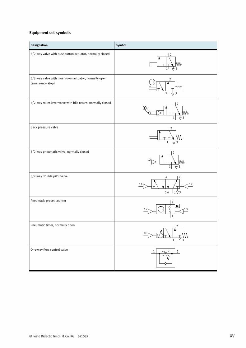
Equipment set symbols
Designation Symbol
3/2-way valve with pushbutton actuator, normally closed 2
31
3/2-way valve with mushroom actuator, normally open
(emergency stop) 2
31
3/2-way roller lever valve with idle return, normally closed 2
31
Back pressure valve
31
2
3/2-way pneumatic valve, normally closed 2
31
12
5/2-way double pilot valve 24
35 1
14 12
Pneumatic preset counter 2
1
12 10
Pneumatic timer, normally open
One-way flow control valve 21

XVI © Festo Didactic GmbH & Co. KG 541089
Designation Symbol
Shuttle valve, 3-way 2 2 2
1 111 1 1
Shuttle valve
Dual-pressure valve, 3-way 2 2 2
1 111 1 1
Double-acting cylinder
Non-return valve, piloted
2
1 21
Designation Symbol
Stepper module
L L
A3 A4
X3 X4
Yn YnYn+1 Yn+1
Zn ZnZn+1 Zn+1
L LL L
P PP P
A2
X2
Yn Yn+1
Zn Zn+1
L L
P P
A1
X1
YnY Yn+1 Yn+1Yn
Zn Zn Zn+1Z Z
L LLL
P PP P PP
Y
TABTAATAATAA
Zn+1
© Festo Didactic GmbH & Co. KG 541089 XVII
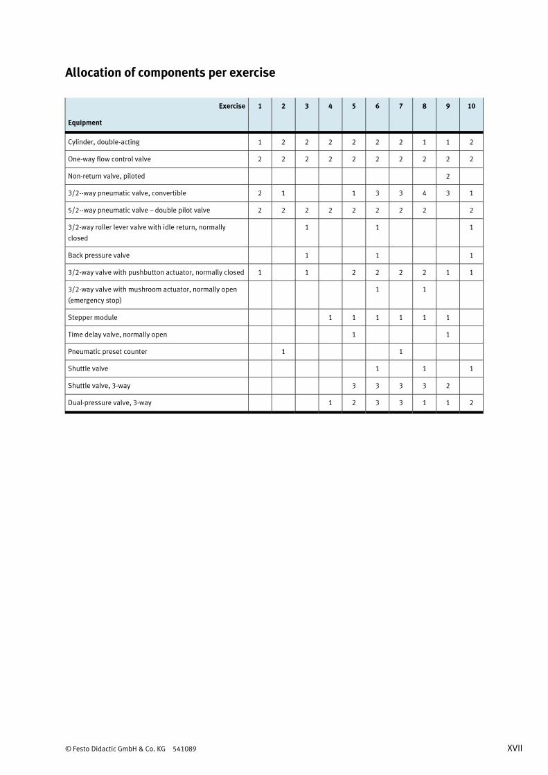
Allocation of components per exercise
Exercise 1 2 3 4 5 6 7 8 9 10
Equipment
Cylinder, double-acting 1 2 2 2 2 2 2 1 1 2
One-way flow control valve 2 2 2 2 2 2 2 2 2 2
Non-return valve, piloted 2
3/2--way pneumatic valve, convertible 2 1 1 3 3 4 3 1
5/2--way pneumatic valve – double pilot valve 2 2 2 2 2 2 2 2 2
3/2-way roller lever valve with idle return, normally
closed
1 1 1
Back pressure valve 1 1 1
3/2-way valve with pushbutton actuator, normally closed 1 1 2 2 2 2 1 1
3/2-way valve with mushroom actuator, normally open
(emergency stop)
1 1
Stepper module 1 1 1 1 1 1
Time delay valve, normally open 1 1
Pneumatic preset counter 1 1
Shuttle valve 1 1 1
Shuttle valve, 3-way 3 3 3 3 2
Dual-pressure valve, 3-way 1 2 3 3 1 1 2

XVIII © Festo Didactic GmbH & Co. KG 541089
Tools for the trainer
Learning objectives
The basic learning objectives for these exercises are the systematic drafting of circuit diagrams, as well as
the practical setup of the controller on the profile plate. This direct interaction involving both theory and
practice ensures faster progress and longer-lasting learning. The more specific learning objectives are
documented in the matrix. Concrete, individual learning objectives are assigned to each exercise.
Required time
The time required for working through the exercises depends on the student's previous knowledge of the
subject matter. For a skilled labourer in the field of metalworking or electrical installation the time required
is approx. 2 weeks. For a technician or engineer it is approx. 1 week.
Equipment set components
The exercise book and the equipment set match each other. For all 10 exercises, you’ll need the components
included in the equipment set for the TP 101 basic level and the TP 102 advanced level.
Each exercise in the basic level can be set up on a profile plate.
Structure of the exercises
All 10 exercises have the same structure and are broken down into:
• Title
• Learning objectives
• Presentation of the problem
• Parameters
and
• Project assignment
• Layout
• Worksheets
The trainer’s manual includes the solutions for all 10 exercises.
Enlarged circuit diagrams are included on A3 paper for exercises 4 through 10.
© Festo Didactic GmbH & Co. KG 541089 XIX
Designations of the components
Pneumatic components are designated in circuit diagrams in accordance with DIN ISO 1219 2. All the
components included in any given circuit have the same primary identifying number. Letters are assigned
depending on each respective type of component. Consecutive numbers are assigned if several components
of the same type are included within a single circuit. Pressure lines are designated with a P and are
numbered separately.
Cylinders: 1A1, 2A1, 2A2 ...
Valves: 1V1, 1V2, 1V3, 2V1, 2V2, 3V1 ...
Sensors: 1B1, 1B2 ...
Signal input: 1S1, 1S2 ...
Accessories: 0Z1, 0Z2, 1Z1 ...
CD-ROM contents
The CD-ROM supplied provides you with additional media. The worksheets and solutions have been saved
as PDF files on the CD-ROM included with the trainer’s manual.
The CD-ROM contains the following folders:
• Operating instructions
• Data sheets
• Demo
• Festo catalogue
• FluidSIM® circuit diagrams
• Industrial applications
• Presentations
• Product information
• Videos
Operating instructions
Operating instructions for various components included in the technology package are available. These
instructions are helpful when using and commissioning the equipment.
Data sheets
The data sheets for the components included in the technology package are supplied along with the
equipment set, and are available as PDF files.
FluidSIM® demo version
A demo version of the FluidSIM® pneumatics software package is included on the CD-ROM. This demo
version is also suitable for testing controllers developed by the user.
XX © Festo Didactic GmbH & Co. KG 541089
Festo catalogue
You’re provided with specific pages from the Festo AG & Co. KG catalogue for selected components. The
representations and descriptions of the components in this format are intended to demonstrate how they
are presented in an industrial catalogue. Additional information regarding the components is also included.
FluidSIM® circuit diagrams
The FluidSIM® circuit diagrams for all 19 exercises included in the technology package are contained in this
directory.
Industrial applications
Photos and graphics representing industrial applications are made available. These can be used to illustrate
individual tasks or to supplement project presentations.
Presentations
This directory contains short presentations for components included in the technology package. They can be
used, for example, for the creation of project presentations.
Product information
This directory contains product information and data sheets from Festo AG & Co. KG for the components
included in the technology package. This is intended to demonstrate which information and data is made
available for industrial components.
Videos
Several short videos of industrial applications in their actual environments round off the media provided
with the technology package.

© Festo Didactic GmbH & Co. KG 541089 XXI
Equipment set for the basic level (TP 101)
The equipment set has been put together for basic training in the field of pneumatic control technology. It
includes all the components which are necessary for mastering the specified learning objectives, and can be
supplemented with any other equipment sets. A profile plate and a source of compressed air are also
required in order to set up functional controllers.
Equipment set for the basic level (TP 101)
Quantity Designation Order no.
2 3/2-way roller lever valve, normally closed 152866
1 3/2-way valve with pushbutton, normally open 152861
2 3/2-way valve with pushbutton, normally closed 152860
1 3/2-way valve with selector switch, normally closed 152863
1 3/2-way valve, pneumatically actuated at one end 539768
3 5/2-way double pilot valve, pneumatically actuated at both ends 539769
1 5/2-way valve with selector switch 152862
1 5/2-way valve, pneumatically actuated at one end 538694
1 Double-acting cylinder 152888
2 One-way flow control valve 193967
2 Pressure gauge 152865
1 Pressure regulator with pressure gauge 539756
1 Pressure sequence valve 152884
1 Single-acting cylinder 152887
1 On-off valve with filter regulator 540691
2 Plastic tubing, 4 x 0.75, silver, 10 m 151496
2 Pneumatic proximity switch with cylinder mounting 539775
1 Pneumatic timer, normally closed 540694
1 Quick exhaust valve 539772
10 Push-in sleeve 153251
10 Push-in T-connector 153128
1 Distributor block 152896
1 Shuttle valve (logical OR) 539771
2 Dual-pressure valve (logical AND) 539770

XXII © Festo Didactic GmbH & Co. KG 541089
Learning objectives for the advanced level (TP 102)
• Detect end-positions without limit switches
• Understand and set up memory circuits (flip-flop, double pilot valve)
• Retrofit a 3/2 and/or a 5/2-way valve
• Evaluate, use and adjust various sensors
• Explain the function of a back-pressure end stop
• Explain the function of stepper modules
• Develop basic sequence control systems (continuous cycle)
• Implement a sequence control system with the following operating modes: automatic/manual, start and
reset
• Implement an OR operation for feedback signals
• Set and coordinate delays
• Be able to abort delay times with an OR operation
• Implement a sequence control system with idle step (3 steps)
• Describe and set up variable step repetition within a motion sequence using a preset counter
• Develop an input circuit with self-latching loop including the following functions: automatic/manual,
start, stop at end of cycle and reset
• Evaluate and use sensors for detecting materials
• Actuate the final control element with two steps via a shuttle valve (double cylinder stroke)
• Use a proximity switch within the stroke sub-range in order to reverse cylinder motion
• Development of an input circuit for a sequence control system with secure pilot air, as well as start,
emergency stop and reset functions
• Stop the cylinder within the sub-stroke range (positioning) through pneumatic actuation at both ends
(preloading)
• Adjust proximity switches in the end positions, and within the sub-stroke range
• Combined use of quick exhaust valve and pressure regulator with pressure gauge
• Set up an inverted timer signal
• Implement a controller with command action in combination with sequence control

© Festo Didactic GmbH & Co. KG 541089 I
Table of contents
Solutions
Exercise 1: Opening and closing an oven door ___________________________________________________ 1
Exercise 2: Separating beverage bottles________________________________________________________ 7
Exercise 3: Drilling manifold blocks _________________________________________________________ 15
Exercise 4: Filling beverage bottles __________________________________________________________ 23
Exercise 5: Cleaning workpieces ____________________________________________________________ 33
Exercise 6: Printing cell phone housings _____________________________________________________ 43
Exercise 7: Packaging spark plugs __________________________________________________________ 51
Exercise 8: Sealing guide bushes ___________________________________________________________ 59
Exercise 9: Hardening material specimens ____________________________________________________ 67
Exercise 10: Bending sheet metal strips ______________________________________________________ 73

II © Festo Didactic GmbH & Co. KG 541089
© Festo Didactic GmbH & Co. KG 541089 1
Exercise 1: Opening and closing an oven door
Learning objectives
After completing this exercise:
• You’ll be familiar with various types of end-position sensing.
• You’ll be familiar with the options for setting up controllers with latching functions.
• You’ll be able to convert 3/2 and/or 5/2-way valves (normally closed/normally open).
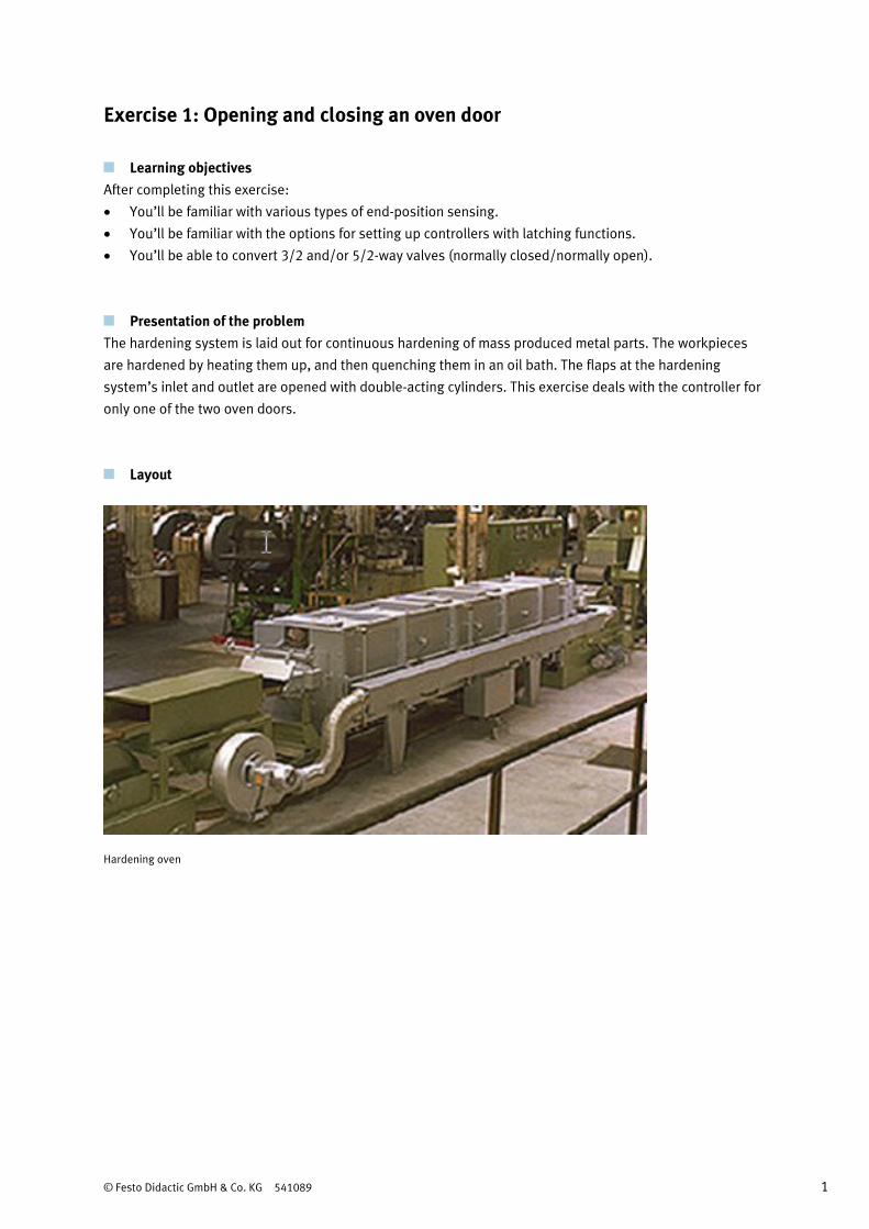
Presentation of the problem
The hardening system is laid out for continuous hardening of mass produced metal parts. The workpieces
are hardened by heating them up, and then quenching them in an oil bath. The flaps at the hardening
system’s inlet and outlet are opened with double-acting cylinders. This exercise deals with the controller for
only one of the two oven doors.
Layout
Hardening oven

Exercise 1: Opening and closing an oven door
2 © Festo Didactic GmbH & Co. KG 541089
Parameters
• Due to the generation of heat, limit switches should not be used. Pressure needs to be sensed when the
cylinder travels into one of its two end-positions.
Procedure
1. Opening and closing is started with a pushbutton.
2. A 5/2-way double pilot valve controls the double-acting cylinder. Pressure which occurs when the
cylinder travels into one of its two end-positions will be used as a control pulse.
3. Either a “retract” pulse is transmitted to valve 1V4 via valves 1V1 and 1V3,
4. Or an “advance” pulse is transmitted to valve 1V4 via valves 1V2 and 1V3.
5. The abbreviated notation for cylinder motion is: 1A1+ 1A1–
Project assignment
1. Complete the pneumatic circuit diagram.
2. Convert the directional control valves included in the equipment set.
3. Set up the controller.
4. Double check the controller configuration.
5. Describe the mode of operation of the controller.
6. Create the equipment list.
Additional exercises
Which errors might occur when connecting the controller’s tubing?
What consequences would these errors have?
The convertible 3/2-way pneumatic valves are earmarked for use as the required 3/2-way valves 1V1 and
1V2. These valves are shipped with a default setting of normally closed. How do they have to be converted
in order to fulfil the required function?
Use 5/2-way valves as an alternative. How do they have to be converted?
How does the controller respond to a pressure drop?

Exercise 1: Opening and closing an oven door
© Festo Didactic GmbH & Co. KG 541089 3
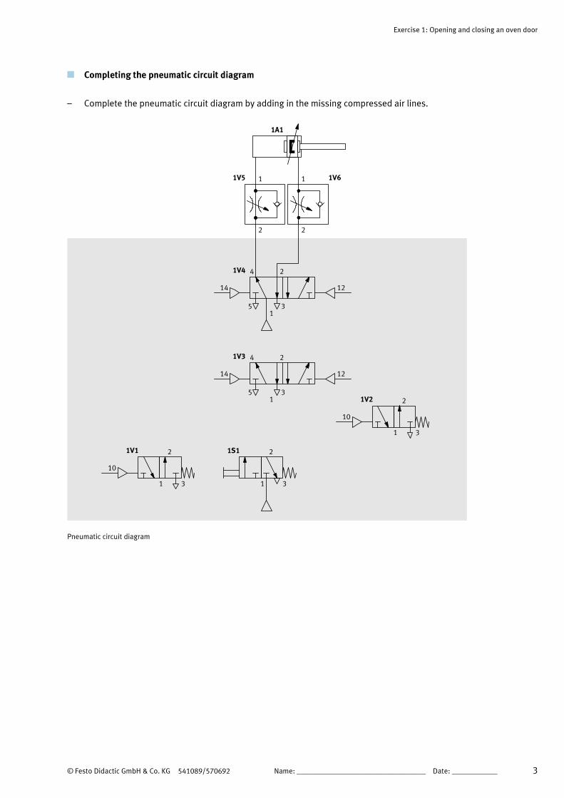
Completing the pneumatic circuit diagram
– Complete the pneumatic circuit diagram by adding in the missing compressed air lines.
1V4
1V3
2
1 1
2 2
2
4
4
3
3
5
5
1
1
1V5
14
14
12
12
1V6
1A1
2
31
1S1
10
10
2
2
3
3
1
1
1V2
1V1
Pneumatic circuit diagram

Exercise 1: Opening and closing an oven door
4 © Festo Didactic GmbH & Co. KG 541089
Sequence description
– Set up the controller and describe the sequence used.
Initial position
The oven door is closed. The piston rod of cylinder 1A1 is advanced. 5/2-way double pilot valve 1V4 (final
control element) pressurises the piston chamber and exhausts the piston rod chamber. 5/2-way double
pilot valve 1V3 (reversing valve) is switched for flow from 1 to 4.
Step 1-2 – Opening the oven door
If the pushbutton at 3/2-way valve 1S1 is pressed, 3/2-way pneumatic valves 1V1 and 1V2 are actuated
simultaneously. Pilot ports 12 and 14 at reversing valve 1V3 are pressurised. Compressed air is now
capable of pressurising pilot port 12 at 5/2-way double pilot valve 1V4 via ports 1 and 4 at 5/2-way
double pilot valve 1V3. Valve 1V4 is reversed as a result. The piston rod side of cylinder 1A1 is
pressurised. The piston travels to its rear end-position.
At the same time, pilot port 12 at reversing valve 1V3 is pressurised with compressed air due to working
air via 3/2-way pneumatic valve 1V2. Reversing valve 1V3 is connected so that final control element 1V4
can be reversed by means of a new start signal.
Step 2-3 – Closing the oven door
If the pushbutton at 3/2-way valve 1S1 is pressed once again, 3/2-way pneumatic valves 1V1 and 1V2
are actuated simultaneously. Pilot ports 12 and 14 at reversing valve 1V3 are pressurised. Compressed
air is now capable of pressurising pilot port 14 at final control element 1V4 via ports 1 and 2 at reversing
valve 1V3. Cylinder 1A1 is pressurised at the piston side. The piston rod advances.
At the same time, pilot port 14 at reversing valve 1V3 is once again pressurised with compressed air due
to working air via 3/2-way pneumatic valve 1V1. The controller is once again in its initial position. The
oven door can be opened again by means of a new start signal.
Exercise 1: Opening and closing an oven door
© Festo Didactic GmbH & Co. KG 541089 5
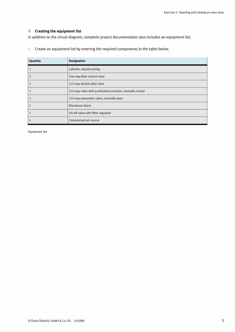
Creating the equipment list
In addition to the circuit diagram, complete project documentation also includes an equipment list.
– Create an equipment list by entering the required components in the table below.
Quantity Designation
1 Cylinder, double-acting
2 One-way flow control valve
2 5/2-way double pilot valve
1 3/2-way valve with pushbutton actuator, normally closed
2 3/2-way pneumatic valve, normally open
1 Distributor block
1 On-off valve with filter regulator
1 Compressed air source
Equipment list

Exercise 1: Opening and closing an oven door
6 © Festo Didactic GmbH & Co. KG 541089
Solutions to additional exercises
The convertible 3/2-way pneumatic valves are earmarked for use as the required 3/2-way valves 1V1 and
1V2. These valves are supplied with a default setting of normally closed.
– How do the 3/2-way valves have to be converted in order to fulfil the required function?
The valves are converted to normally open by interchanging the blanking plug and the working port.
– Which errors might occur when connecting the controller’s tubing? What consequences would these
errors have? Describe the errors.
If the 3/2-way valves have not been correctly converted, the controller doesn’t work.
If ports 2 and 4 are reversed at valve 1V4, the cylinder doesn’t advance.
– Use 5/2-way valves as an alternative. How do they have to be converted? How do the 5/2-way
pneumatic valves have to be converted?
Working port 4 has to be plugged.
Note
Possible solution in the event that a plug is not available: connect a barbed T-connector to the valve,
using a short tube. Connect the remaining outlets of the barbed T-connector to each other with a short
tube.
– How does the controller respond to a pressure drop?
The controller retains its status in memory. Result: if the door moves when pressure drops, it returns to
its last position when pressure is restored.

© Festo Didactic GmbH & Co. KG 541089/570692 1
Exercise 1: Opening and closing an oven door
Learning objectives
After completing this exercise:
• You’ll be familiar with various types of end-position sensing.
• You’ll be familiar with the options for setting up controllers with latching functions.
• You’ll be able to convert 3/2 and/or 5/2-way valves (normally closed/normally open).
Presentation of the problem
The hardening system is laid out for continuous hardening of mass produced metal parts. The workpieces
are hardened by heating them up, and then quenching them in an oil bath. The flaps at the hardening
system’s inlet and outlet are opened with double-acting cylinders. This exercise deals with the controller for
only one of the two oven doors.
Layout
Hardening oven

Exercise 1: Opening and closing an oven door
2 Name: __________________________________ Date: ____________ © Festo Didactic GmbH & Co. KG 541089/570692
Parameters
• Due to the generation of heat, limit switches should not be used. Pressure needs to be sensed when the
cylinder travels into one of its two end-positions.
Procedure
1. Opening and closing is started with a pushbutton.
2. A 5/2-way double pilot valve controls the double-acting cylinder. Pressure which occurs when the
cylinder travels into one of its two end-positions will be used as a control pulse.
3. Either a “retract” pulse is transmitted to valve 1V4 via valves 1V1 and 1V3,
4. Or an “advance” pulse is transmitted to valve 1V4 via valves 1V2 and 1V3.
5. The abbreviated notation for cylinder motion is: 1A1+ 1A1–
Project assignment
1. Complete the pneumatic circuit diagram.
2. Convert the directional control valves included in the equipment set.
3. Set up the controller.
4. Double check the controller configuration.
5. Describe the mode of operation of the controller.
6. Create the equipment list.
Additional exercises
Which errors might occur when connecting the controller’s tubing?
What consequences would these errors have?
The convertible 3/2-way pneumatic valves are earmarked for use as the required 3/2-way valves 1V1 and
1V2. These valves are shipped with a default setting of normally closed. How do they have to be converted
in order to fulfil the required function?
Use 5/2-way valves as an alternative. How do they have to be converted?
How does the controller respond to a pressure drop?
Exercise 1: Opening and closing an oven door
© Festo Didactic GmbH & Co. KG 541089/570692 Name: __________________________________ Date: ____________ 3
Completing the pneumatic circuit diagram
– Complete the pneumatic circuit diagram by adding in the missing compressed air lines.
1V4
1V3
2
1 1
2 2
2
4
4
3
3
5
5
1
1
1V5
14
14
12
12
1V6
2
31
1S1
10
10
2
2
3
3
1
1
1V2
1V1
1A1
Pneumatic circuit diagram

Exercise 1: Opening and closing an oven door
4 Name: __________________________________ Date: ____________ © Festo Didactic GmbH & Co. KG 541089/570692
Sequence description
– Set up the controller and describe the sequence used.
Initial position
_________________________________________________________________________________________
_________________________________________________________________________________________
_________________________________________________________________________________________
_________________________________________________________________________________________
_________________________________________________________________________________________
_________________________________________________________________________________________
Step 1-2 – Opening the oven door
_________________________________________________________________________________________
_________________________________________________________________________________________
_________________________________________________________________________________________
_________________________________________________________________________________________
_________________________________________________________________________________________
_________________________________________________________________________________________
Step 2-3 – Closing the oven door
_________________________________________________________________________________________
_________________________________________________________________________________________
_________________________________________________________________________________________
_________________________________________________________________________________________
_________________________________________________________________________________________
_________________________________________________________________________________________

Exercise 1: Opening and closing an oven door
© Festo Didactic GmbH & Co. KG 541089/570692 Name: __________________________________ Date: ____________ 5
Creating the equipment list
In addition to the circuit diagram, complete project documentation also includes an equipment list.
– Create an equipment list by entering the required components in the table below.
Quantity Designation
Equipment list

Exercise 1: Opening and closing an oven door
6 Name: __________________________________ Date: ____________ © Festo Didactic GmbH & Co. KG 541089/570692
Solutions to additional exercises
The convertible 3/2-way pneumatic valves are earmarked for use as the required 3/2-way valves 1V1 and
1V2. These valves are supplied with a default setting of normally closed.
– How do the 3/2-way valves have to be converted in order to fulfil the required function?
_________________________________________________________________________________________
_________________________________________________________________________________________
_________________________________________________________________________________________
– Which errors might occur when connecting the controller’s tubing? What consequences would these
errors have? Describe the errors.
_________________________________________________________________________________________
_________________________________________________________________________________________
_________________________________________________________________________________________
– Use 5/2-way valves as an alternative. How do they have to be converted? How do the 5/2-way
pneumatic valves have to be converted?
_________________________________________________________________________________________
_________________________________________________________________________________________
_________________________________________________________________________________________
Note
Possible solution in the event that a plug is not available: connect a barbed T-connector to the valve,
using a short tube. Connect the remaining outlets of the barbed T-connector to each other with a short
tube.
– How does the controller respond to a pressure drop?
_________________________________________________________________________________________
_________________________________________________________________________________________
_________________________________________________________________________________________
Related Documents