30 0 kN 10 kN 20 kN 30 kN 40 kN 50 kN 60 kN 70 kN 80 kN 5.0 mm 4.5 mm 4.0 mm 3.5 mm 3.0 mm 2.5 mm 2.0 mm 1.5 mm 1.0 mm 0.5 mm 0.0 mm APK 2 L VKL 500 APK 3 L VKL 1000 APK 4 L VKL 2400 APK 5 L VKL 3200 APK 6 L VKL 6000 E K F B A G D E F B K D G C A E E M6 6,25 APK 2L DP VKL 0500 DP 8 E APK 2L VKL 0500 E M6 E B G D A F C K E APK 6L VKL 6000 E 15 M10 E 10 M8 E APK 3L APK 4L APK 5L VKL 1000 VKL 2400 VKL 3200 E C Request CAD at www.maederpressen.de or directly from Tel.+49 (0)7467-9467-0 Pneumatic toggle presses The accessories Square Ram Pneumatic toggle presses APK*L and VKL range The optimum transmission ratio of the toggle lever produces large forces at the end of the stroke and ensures low air consumption. The resulting low energy consumption means that mäder pneumatic toggle presses are a cost-effective production tool, not only at the procurement stage but also in the long term. All pneumatic toggle presses can be provided with the standard mäder MPS-1 controller or with customer-specified controllers. Other quality features: Factory pre-set pressure point Right-angled gearbox for simple height adjustment of the press head Side-mounted measuring strip for fast reproduction of settings when changing the tool Practically maintenance-free double-acting cylinder Low noise: less than 75 dB APK 2L VKL 0500-35-80 APK 4L APK 5L APK 6L APK 3L VKL 1000-40-100 Before end of stroke Standard With DP VKL 2400 VKL 3200 VKL 6000

Welcome message from author
This document is posted to help you gain knowledge. Please leave a comment to let me know what you think about it! Share it to your friends and learn new things together.
Transcript
30
0 kN
10 kN
20 kN
30 kN
40 kN
50 kN
60 kN
70 kN
80 kN
5.0 mm 4.5 mm 4.0 mm 3.5 mm 3.0 mm 2.5 mm 2.0 mm 1.5 mm 1.0 mm 0.5 mm 0.0 mm
APK 2 LVKL 500
APK 3 LVKL 1000
APK 4 LVKL 2400
APK 5 L VKL 3200
APK 6 LVKL 6000
vor Hubende
E
E
E K
F
B
A
C
G
10
E
M8
D
APK 4 LAPK 5 LVKL 2400VKL 3200
EF
B
K
D
G
C
A
8
E
APK 2LVKL 0500E
M6
E
E
M6
6,25
APK 2L DPVKL 0500 DP
EF
B
K
D
G
C
A
8
E
APK 2LVKL 0500E
M6
E
E
M6
6,25
APK 2L DPVKL 0500 DP
EF
B
K
D
G
C
A
8
E
APK 2LVKL 0500E
M6
E
E
M6
6,25
APK 2L DPVKL 0500 DP
E
B
G
D
A
F
C
K
E
APK 6LVKL 6000
E
10
M8
E
APK 3LAPK 4LAPK 5LVKL 1000VKL 2400VKL 3200
E
15
M10
E
B
G
D
A
F
C
K
E
APK 6LVKL 6000
E
10
M8
E
APK 3LAPK 4LAPK 5LVKL 1000VKL 2400VKL 3200
E
15
M10
E
B
G
D
A
F
C
K
E
APK 6LVKL 6000
E
10
M8
E
APK 3LAPK 4LAPK 5LVKL 1000VKL 2400VKL 3200
E
15
M10
E
E
E K
F
B
A
C
G
10
E
M8
D
APK 4 LAPK 5 LVKL 2400VKL 3200
Request CAD at www.maederpressen.de or directly from Tel.+49 (0)7467-9467-0
Pneumatic toggle presses
The accessories
Square Ram
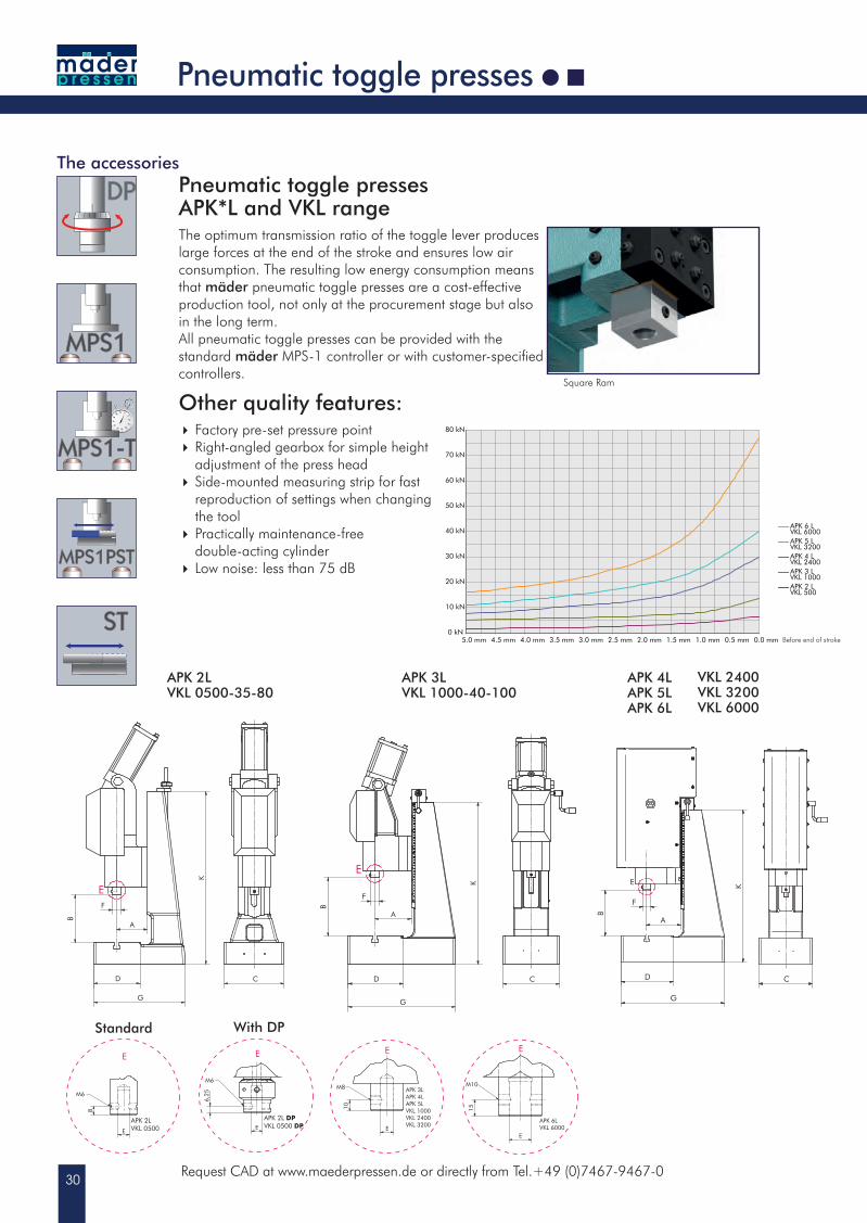
Pneumatic toggle presses APK*L and VKL rangeThe optimum transmission ratio of the toggle lever produces large forces at the end of the stroke and ensures low air consumption. The resulting low energy consumption means that mäder pneumatic toggle presses are a cost-effective production tool, not only at the procurement stage but also in the long term.All pneumatic toggle presses can be provided with the standard mäder MPS-1 controller or with customer-specified controllers.
Other quality features: Factory pre-set pressure point Right-angled gearbox for simple height adjustment of the press head Side-mounted measuring strip for fast
reproduction of settings when changing the tool Practically maintenance-free
double-acting cylinder Low noise: less than 75 dB
APK 2LVKL 0500-35-80
APK 4LAPK 5LAPK 6L
APK 3LVKL 1000-40-100
Before end of stroke
Standard With DP
VKL 2400VKL 3200VKL 6000
31
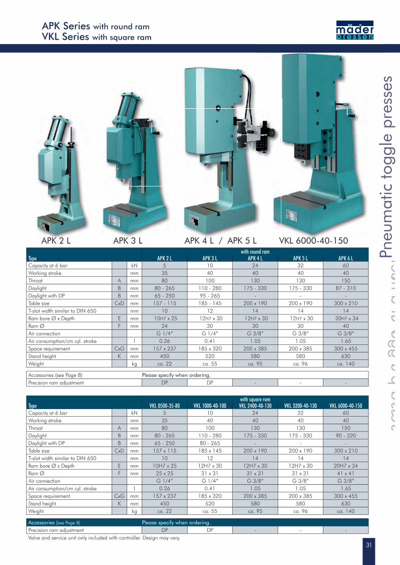
with round ramType APK 2 L APK 3 L APK 4 L APK 5 L APK 6 LCapacity at 6 bar kN 5 10 24 32 60Working stroke mm 35 40 40 40 40Throat A mm 80 100 130 130 150Daylight B mm 80 - 265 110 - 280 175 - 330 175 - 330 87 - 310Daylight with DP B mm 65 - 250 95 - 265 - - -Table size CxD mm 157 - 115 185 - 145 200 x 190 200 x 190 300 x 210T-slot width similar to DIN 650 mm 10 12 14 14 14Ram bore Ø x Depth E mm 10H7 x 25 12H7 x 30 12H7 x 30 12H7 x 30 20H7 x 34Ram Ø F mm 24 30 30 30 40Air connection G 1/4“ G 1/4“ G 3/8“ G 3/8“ G 3/8“Air consumption/cm cyl. stroke l 0.26 0.41 1.05 1.05 1.65Space requirement CxG mm 157 x 237 185 x 320 200 x 385 200 x 385 300 x 455Stand height K mm 450 520 580 580 630Weight kg ca. 22 ca. 55 ca. 95 ca. 96 ca. 140
Accessories (see Page 8) Please specify when ordering.Precision ram adjustment DP DP - - -
with square ramType VKL 0500-35-80 VKL 1000-40-100 VKL 2400-40-130 VKL 3200-40-130 VKL 6000-40-150Capacity at 6 bar kN 5 10 24 32 60Working stroke mm 35 40 40 40 40Throat A mm 80 100 130 130 150Daylight B mm 80 - 265 110 - 280 175 - 330 175 - 330 90 - 320Daylight with DP B mm 65 - 250 80 - 265 - - -Table size CxD mm 157 x 115 185 x 145 200 x 190 200 x 190 300 x 210T-slot width similar to DIN 650 mm 10 12 14 14 14Ram bore Ø x Depth E mm 10H7 x 25 12H7 x 30 12H7 x 30 12H7 x 30 20H7 x 34Ram Ø F mm 25 x 25 31 x 31 31 x 31 31 x 31 41 x 41Air connection G 1/4“ G 1/4“ G 3/8“ G 3/8“ G 3/8“Air consumption/cm cyl. stroke l 0.26 0.41 1.05 1.05 1.65Space requirement CxG mm 157 x 237 185 x 320 200 x 385 200 x 385 300 x 455Stand height K mm 450 520 580 580 630Weight kg ca. 22 ca. 55 ca. 95 ca. 96 ca. 140
Accessories (see Page 8) Please specify when ordering.Precision ram adjustment DP DP - - -Valve and service unit only included with controller. Design may vary.
APK 2 L
APK Series with round ramVKL Series with square ram
APK 4 L / APK 5 L VKL 6000-40-150
Pneu
mat
ic to
ggle
pre
sses
Pneumatic toggle presses
Pneu
mat
ic to
ggle
pre
sses
Pneumatic toggle presses
Pneu
mat
ic to
ggle
pre
sses
Before end of stroke
APK 3 L
32
E
E
B
G
K
BB
FA
H C
D
15
E
M10
XL-APK 6 LXL-VKL 6000
E
0 kN
10 kN
20 kN
30 kN
40 kN
50 kN
60 kN
70 kN
80 kN
5.0 mm 4.5 mm 4.0 mm 3.5 mm 3.0 mm 2.5 mm 2.0 mm 1.5 mm 1.0 mm 0.5 mm 0.0 mm
XL-APK 4 LXL-VKL 2400
XL-APK 5 L XL-VKL 3200
XL-APK 6 LXL-VKL 6000
E
A
F
B
D
G
C
K
BB
H
10
E
M8
E
15
M10
E
E
XL-APK 4LXL-APK 5LXL-VKL 2400XL-VKL 3200
XL-APK 6LXL-VKL 6000
E
E
B
G
K
BB
FA
H C
D
15
E
M10
XL-APK 6 LXL-VKL 6000
E
Request CAD at www.maederpressen.de or directly from Tel.+49 (0)7467-9467-0
XL-Pneumatic toggle presses
The accessories
Square ram
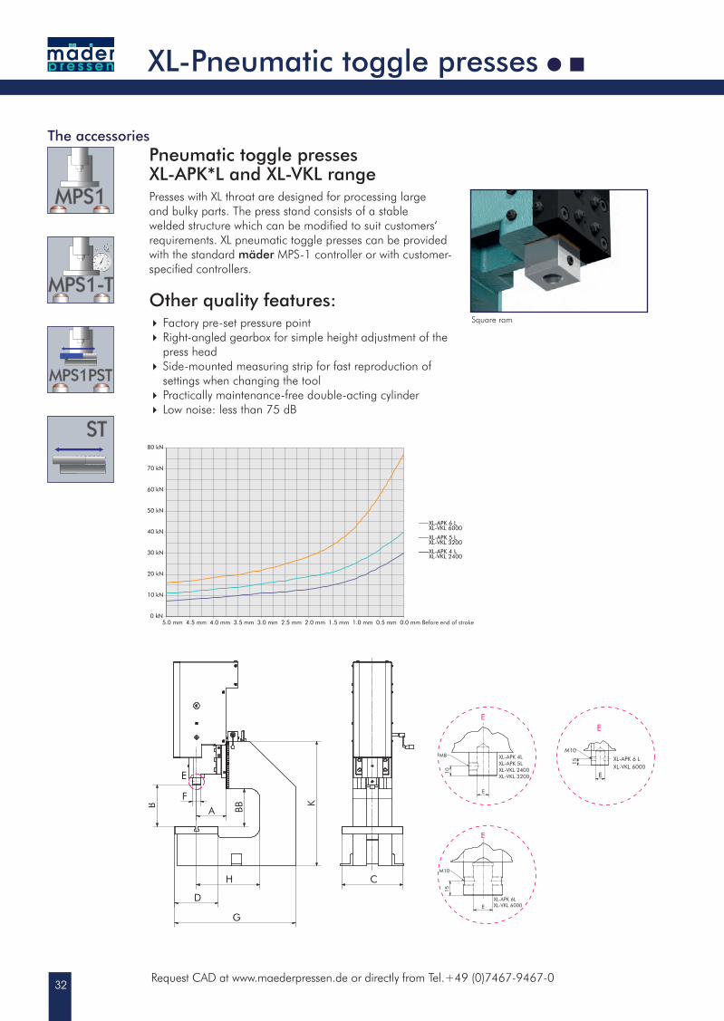
Pneumatic toggle presses XL-APK*L and XL-VKL range Presses with XL throat are designed for processing large and bulky parts. The press stand consists of a stable welded structure which can be modified to suit customers‘ requirements. XL pneumatic toggle presses can be provided with the standard mäder MPS-1 controller or with customer-specified controllers.
Other quality features: Factory pre-set pressure point Right-angled gearbox for simple height adjustment of the press head Side-mounted measuring strip for fast reproduction of settings when changing the tool Practically maintenance-free double-acting cylinder Low noise: less than 75 dB
Before end of stroke
33
XL-APK 6 LPn
eum
atic
togg
le p
ress
es
Pneumatic toggle presses
Pneu
mat
ic to
ggle
pre
sses
Pneumatic toggle presses
Pneu
mat
ic to
ggle
pre
sses
XL-APK Series with round ram 300 mm throatXL-VKL Series with square ram 300 mm throat
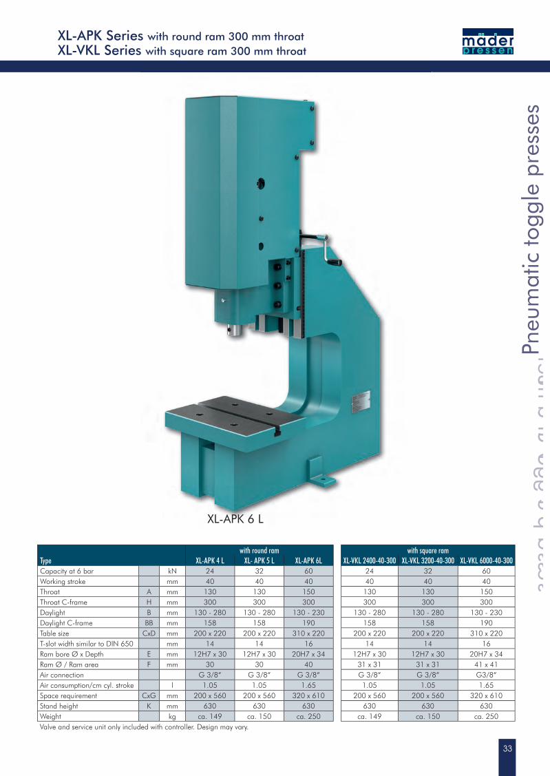
with round ram with square ramType XL-APK 4 L XL- APK 5 L XL-APK 6L XL-VKL 2400-40-300 XL-VKL 3200-40-300 XL-VKL 6000-40-300Capacity at 6 bar kN 24 32 60 24 32 60Working stroke mm 40 40 40 40 40 40Throat A mm 130 130 150 130 130 150Throat C-frame H mm 300 300 300 300 300 300Daylight B mm 130 - 280 130 - 280 130 - 230 130 - 280 130 - 280 130 - 230Daylight C-frame BB mm 158 158 190 158 158 190Table size CxD mm 200 x 220 200 x 220 310 x 220 200 x 220 200 x 220 310 x 220T-slot width similar to DIN 650 mm 14 14 16 14 14 16Ram bore Ø x Depth E mm 12H7 x 30 12H7 x 30 20H7 x 34 12H7 x 30 12H7 x 30 20H7 x 34Ram Ø / Ram area F mm 30 30 40 31 x 31 31 x 31 41 x 41Air connection G 3/8“ G 3/8“ G 3/8“ G 3/8“ G 3/8“ G3/8“Air consumption/cm cyl. stroke l 1.05 1.05 1.65 1.05 1.05 1.65Space requirement CxG mm 200 x 560 200 x 560 320 x 610 200 x 560 200 x 560 320 x 610Stand height K mm 630 630 630 630 630 630Weight kg ca. 149 ca. 150 ca. 250 ca. 149 ca. 150 ca. 250Valve and service unit only included with controller. Design may vary.
34
0.0 mm 10.0 mm 20.0 mm 30.0 mm 40.0 mm 1.0 mm 2.0 mm 3.0 mm 4.0 mm 5.0 mm 6.0 mm0 kN
5 kN
10 kN
15 kN
20 kN
25 kN
30 kN
35 kN
40 kN
45 kN
NP 2000
Manual feed stroke Pneumatic power stroke
NP 4000
E
A
B
BB
H
G
D
K
C
F 20
EM10
E
XL-NP
E
A
F
G
CD
B
K
E
20
M10
E
NP
E
A
F
G
CD
B
K
E
20
M10
E
Hubeinstellung
Request CAD at www.maederpressen.de or directly from Tel.+49 (0)7467-9467-0
Manually assisted pneumatic toggle presses with square ram
The accessories
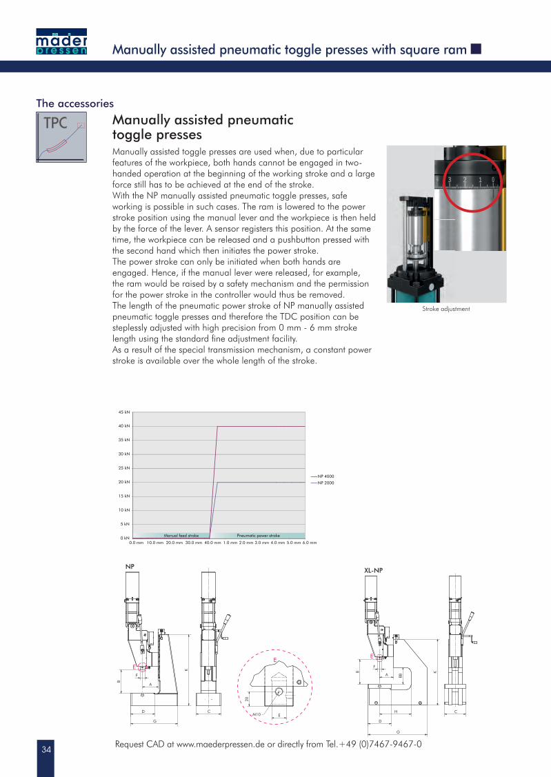
Stroke adjustment
Manually assisted pneumatic toggle pressesManually assisted toggle presses are used when, due to particular features of the workpiece, both hands cannot be engaged in two-handed operation at the beginning of the working stroke and a large force still has to be achieved at the end of the stroke.With the NP manually assisted pneumatic toggle presses, safe working is possible in such cases. The ram is lowered to the power stroke position using the manual lever and the workpiece is then held by the force of the lever. A sensor registers this position. At the same time, the workpiece can be released and a pushbutton pressed with the second hand which then initiates the power stroke.The power stroke can only be initiated when both hands are engaged. Hence, if the manual lever were released, for example, the ram would be raised by a safety mechanism and the permission for the power stroke in the controller would thus be removed.The length of the pneumatic power stroke of NP manually assisted pneumatic toggle presses and therefore the TDC position can be steplessly adjusted with high precision from 0 mm - 6 mm stroke length using the standard fi ne adjustment facility.As a result of the special transmission mechanism, a constant power stroke is available over the whole length of the stroke.
35
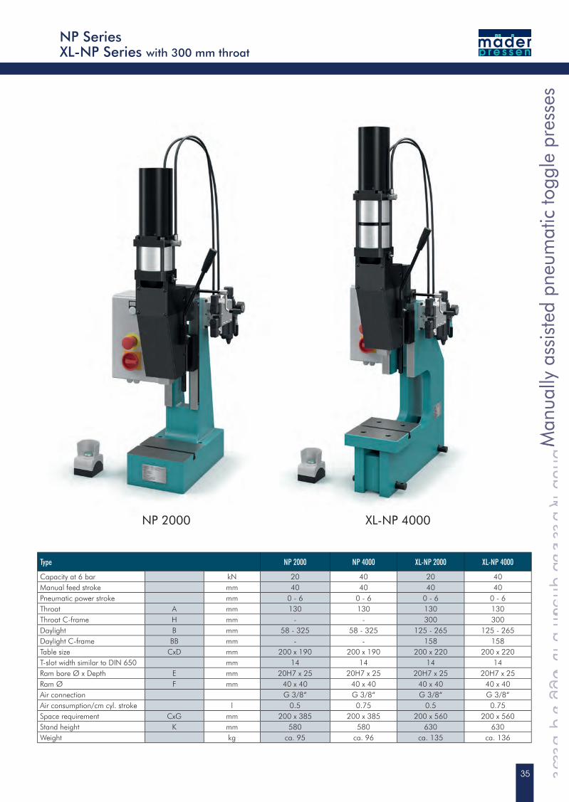
XL-NP 4000
Man
ually
ass
iste
d pn
eum
atic
togg
le p
ress
es
Manually assisted pneumatic toggle presses
Man
ually
ass
iste
d pn
eum
atic
togg
le p
ress
es
Manually assisted pneumatic toggle presses
Man
ually
ass
iste
d pn
eum
atic
togg
le p
ress
es
NP SeriesXL-NP Series with 300 mm throat
Type NP 2000 NP 4000 XL-NP 2000 XL-NP 4000
Capacity at 6 bar kN 20 40 20 40Manual feed stroke mm 40 40 40 40Pneumatic power stroke mm 0 - 6 0 - 6 0 - 6 0 - 6Throat A mm 130 130 130 130Throat C-frame H mm - - 300 300Daylight B mm 58 - 325 58 - 325 125 - 265 125 - 265Daylight C-frame BB mm - - 158 158Table size CxD mm 200 x 190 200 x 190 200 x 220 200 x 220T-slot width similar to DIN 650 mm 14 14 14 14Ram bore Ø x Depth E mm 20H7 x 25 20H7 x 25 20H7 x 25 20H7 x 25Ram Ø F mm 40 x 40 40 x 40 40 x 40 40 x 40Air connection G 3/8“ G 3/8“ G 3/8“ G 3/8“Air consumption/cm cyl. stroke l 0.5 0.75 0.5 0.75Space requirement CxG mm 200 x 385 200 x 385 200 x 560 200 x 560Stand height K mm 580 580 630 630Weight kg ca. 95 ca. 96 ca. 135 ca. 136
NP 2000
36Request CAD at www.maederpressen.de or directly from Tel.+49 (0)7467-9467-0
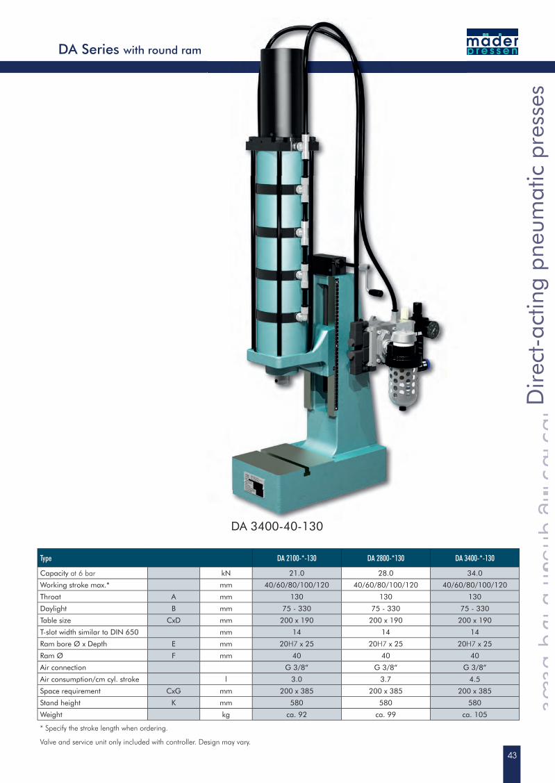
Direct-acting pneumatic presses
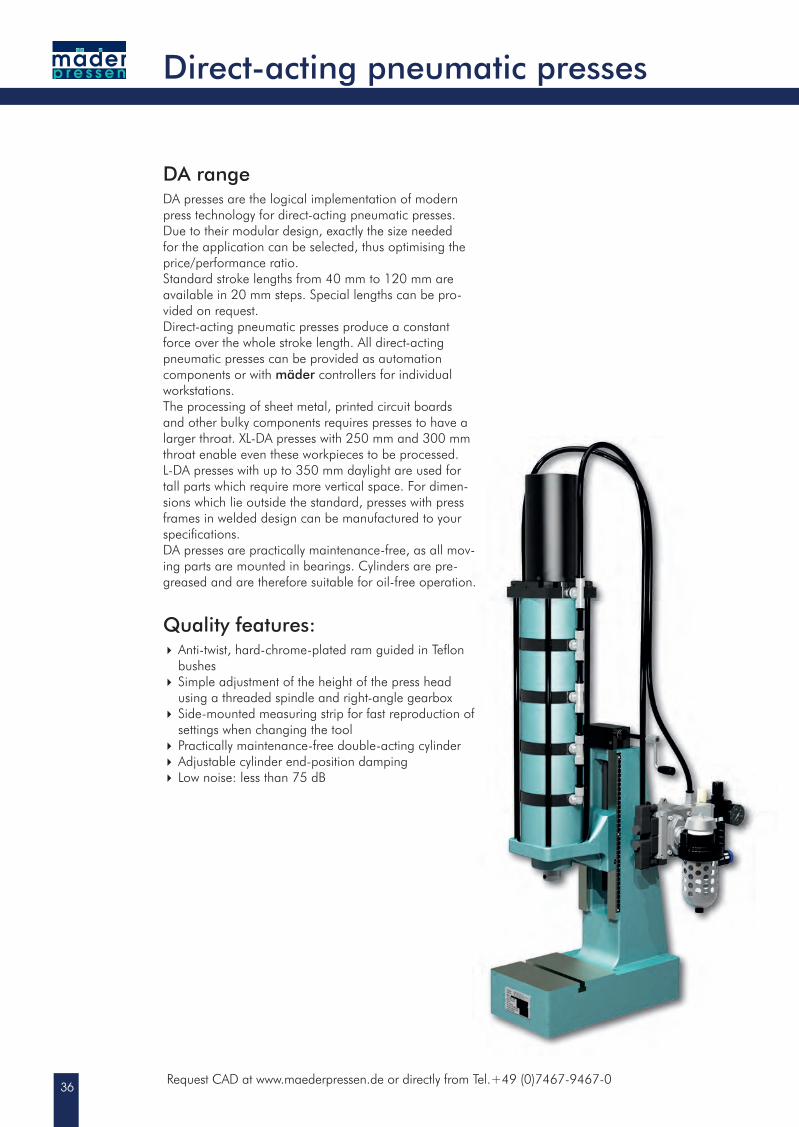
DA rangeDA presses are the logical implementation of modern press technology for direct-acting pneumatic presses. Due to their modular design, exactly the size needed for the application can be selected, thus optimising the price/performance ratio.Standard stroke lengths from 40 mm to 120 mm are available in 20 mm steps. Special lengths can be pro-vided on request.Direct-acting pneumatic presses produce a constant force over the whole stroke length. All direct-acting pneumatic presses can be provided as automation components or with mäder controllers for individual workstations.The processing of sheet metal, printed circuit boards and other bulky components requires presses to have a larger throat. XL-DA presses with 250 mm and 300 mm throat enable even these workpieces to be processed. L-DA presses with up to 350 mm daylight are used fortall parts which require more vertical space. For dimen-sions which lie outside the standard, presses with pressframes in welded design can be manufactured to yourspecifi cations.DA presses are practically maintenance-free, as all mov- ing parts are mounted in bearings. Cylinders are pre-greased and are therefore suitable for oil-free operation.
Quality features: Anti-twist, hard-chrome-plated ram guided in Tefl on bushes Simple adjustment of the height of the press head
using a threaded spindle and right-angle gearbox Side-mounted measuring strip for fast reproduction of
settings when changing the tool Practically maintenance-free double-acting cylinder Adjustable cylinder end-position damping Low noise: less than 75 dB
37
Sensors are not included
Dire
ct-a
ctin
g pn
eum
atic
pre
sses
Direct-acting pneumatic presses
Dire
ct-a
ctin
g pn
eum
atic
pre
sses
Direct-acting pneumatic presses
Dire
ct-a
ctin
g pn
eum
atic
pre
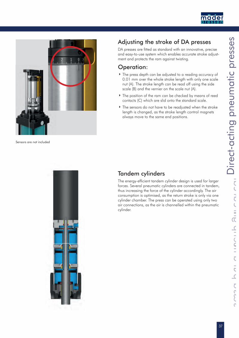
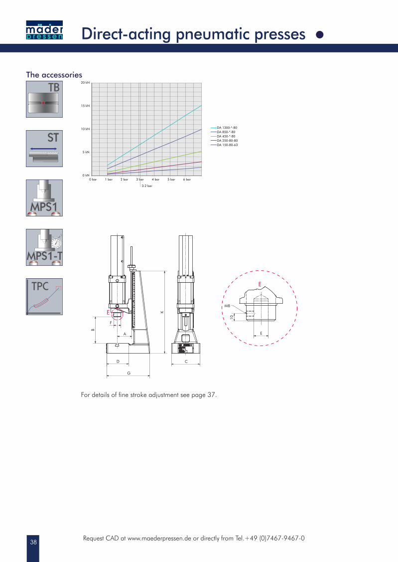
ssesAdjusting the stroke of DA presses
DA presses are fi tted as standard with an innovative, precise and easy-to-use system which enables accurate stroke adjust-ment and protects the ram against twisting.
Operation: The press depth can be adjusted to a reading accuracy of
0.01 mm over the whole stroke length with only one scale nut (A). The stroke length can be read off using the side scale (B) and the vernier on the scale nut (A).
The position of the ram can be checked by means of reed contacts (C) which are slid onto the standard scale.
The sensors do not have to be readjusted when the stroke length is changed, as the stroke length control magnets always move to the same end positions.
Tandem cylindersThe energy-effi cient tandem cylinder design is used for larger forces. Several pneumatic cylinders are connected in tandem, thus increasing the force of the cylinder accordingly. The air consumption is optimised, as the return stroke is only via one cylinder chamber. The press can be operated using only two air connections, as the air is channelled within the pneumatic cylinder.
38
3 bar0 bar 1 bar 2 bar 4 bar 5 bar 6 bar0 kN
5 kN
10 kN
15 kN
20 kN
DA 150-80-63DA 250-80-80DA 450-*-80DA 850-*-80DA 1300-*-80
3.2 bar
C
E
10
M8
E
E
B
F
A
G
D
K
C
E
10
M8
E
E
B
F
A
G
D
K
Request CAD at www.maederpressen.de or directly from Tel.+49 (0)7467-9467-0
Direct-acting pneumatic presses
The accessories
For details of fine stroke adjustment see page 37.
39
DA 150-80-63
Dire
ct-a
ctin
g pn
eum
atic
pre
sses
Direct-acting pneumatic presses
Dire
ct-a
ctin
g pn
eum
atic
pre
sses
Direct-acting pneumatic presses
Dire
ct-a
ctin
g pn
eum
atic
pre
sses
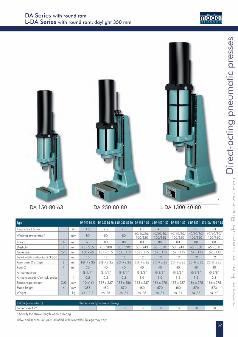
Type DA 150-80-63 DA 250-80-80 L-DA 250-80-80 DA 450-*-80 L-DA 450-*-80 DA 850-*-80 L-DA 850-*-80 L-DA 1300-*-80
Capacity at 6 bar kN 1.5 2.5 2.5 4.5 4.5 8.5 8.5 13
Working stroke max.* mm 80 80 8040/60/80/100/120
40/60/80/100/120
40/60/80/100/120
40/60/80/100/120
40/60/80/100/120
Throat A mm 63 80 80 80 80 80 80 80
Daylight B mm 40 - 215 70 - 280 65 - 390 58 - 243 65 - 350 58 - 243 65 - 350 65 - 350
Table size CxD mm 100 x 65 157 x 115 157 x 115 157 x 115 157 x 115 157 x 115 157 x 115 157 x 115
T-slot width similar to DIN 650 mm 10 12 12 12 12 12 12 12
Ram bore Ø x Depth E mm 16H7 x 25 20H7 x 25 20H7 x 25 20H7 x 25 20H7 x 25 20H7 x 25 20H7 x 25 20H7 x 25
Ram Ø F mm 30 40 40 40 40 40 40 40
Air connection G 1/4“ G 1/4“ G 1/4“ G 3/8“ G 3/8“ G 3/8“ G 3/8“ G 3/8“
Air consumption/cm cyl. stroke l 0.2 0.3 0.3 1.0 1.0 1.5 1.5 2.1
Space requirement CxG mm 110 x164 157 x 237 155 x 280 155 x 237 156 x 275 155 x 237 156 x 275 156 x 275
Stand height K mm 355 450 570 450 570 450 570 570
Weight kg ca. 11.5 ca. 25 ca. 31 ca. 28 ca. 34 ca. 31 ca. 37 ca. 40
Extras (siehe Seite 8 ) Please specify when ordering.
Table bore 12H7 TB TB TB TB TB TB TB TB
* Specify the stroke length when ordering.
Valve and service unit only included with controller. Design may vary.
DA Series with round ramL-DA Series with round ram, daylight 350 mm
DA 250-80-80 L-DA 1300-40-80
40
0 kN
5 kN
10 kN
15 kN
20 kN
25 kN
0 bar 1 bar 2 bar 3 bar 4 bar 5 bar 6 bar
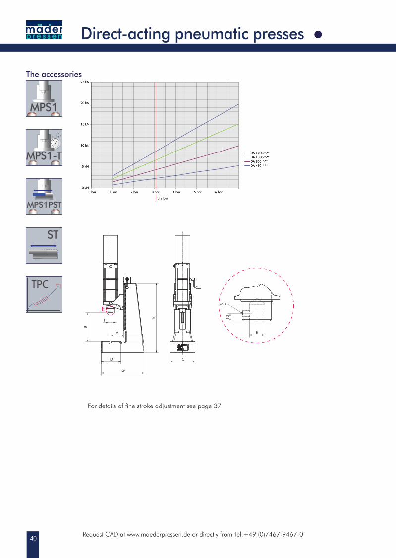
DA 450-*-**DA 850-*-**DA 1300-*-**DA 1700-*-**
E
E
B
F
A
G
D C
10
M8
E
K
Request CAD at www.maederpressen.de or directly from Tel.+49 (0)7467-9467-0
Direct-acting pneumatic presses
0 kN
5 kN
10 kN
15 kN
20 kN
25 kN
0 bar 1 bar 2 bar 3 bar 4 bar 5 bar 6 bar
DA 450-*-**DA 850-*-**DA 1300-*-**DA 1700-*-**
3.2 bar
The accessories
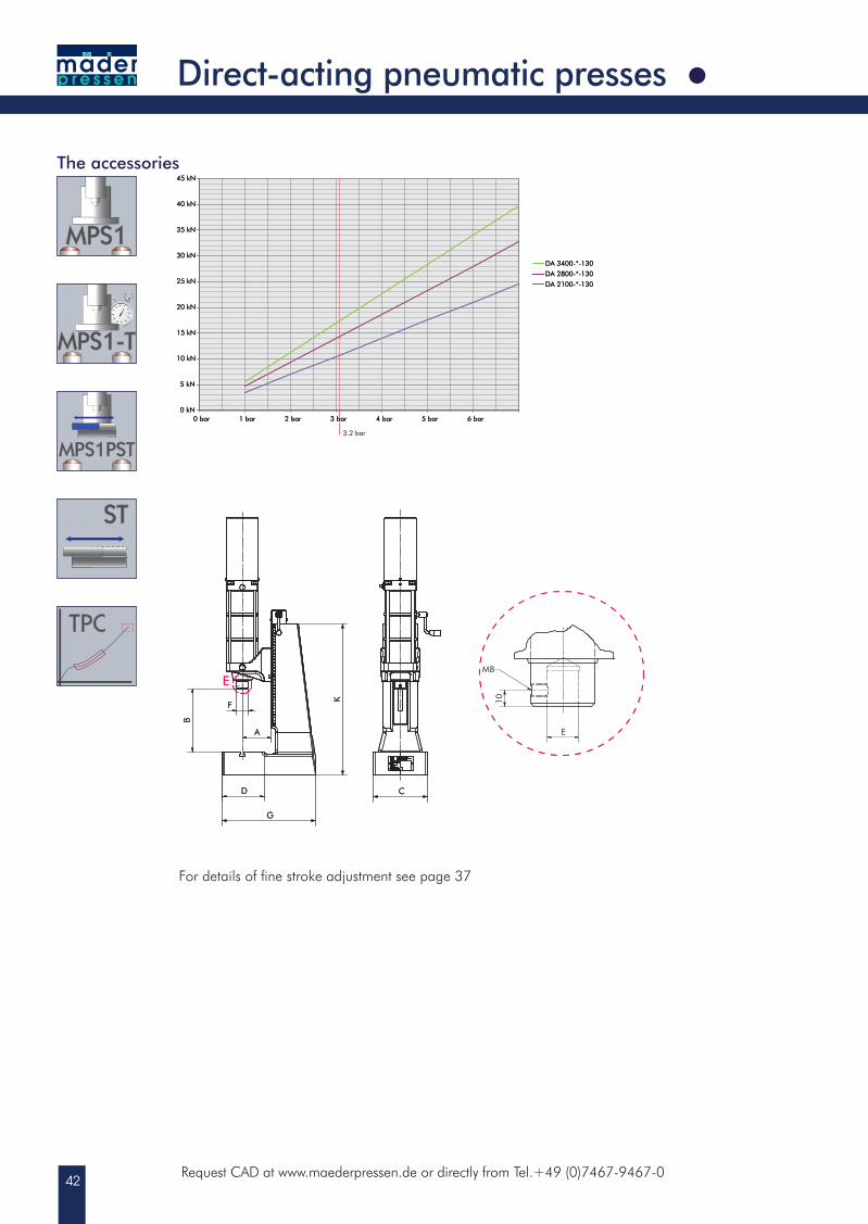
For details of fine stroke adjustment see page 37
41
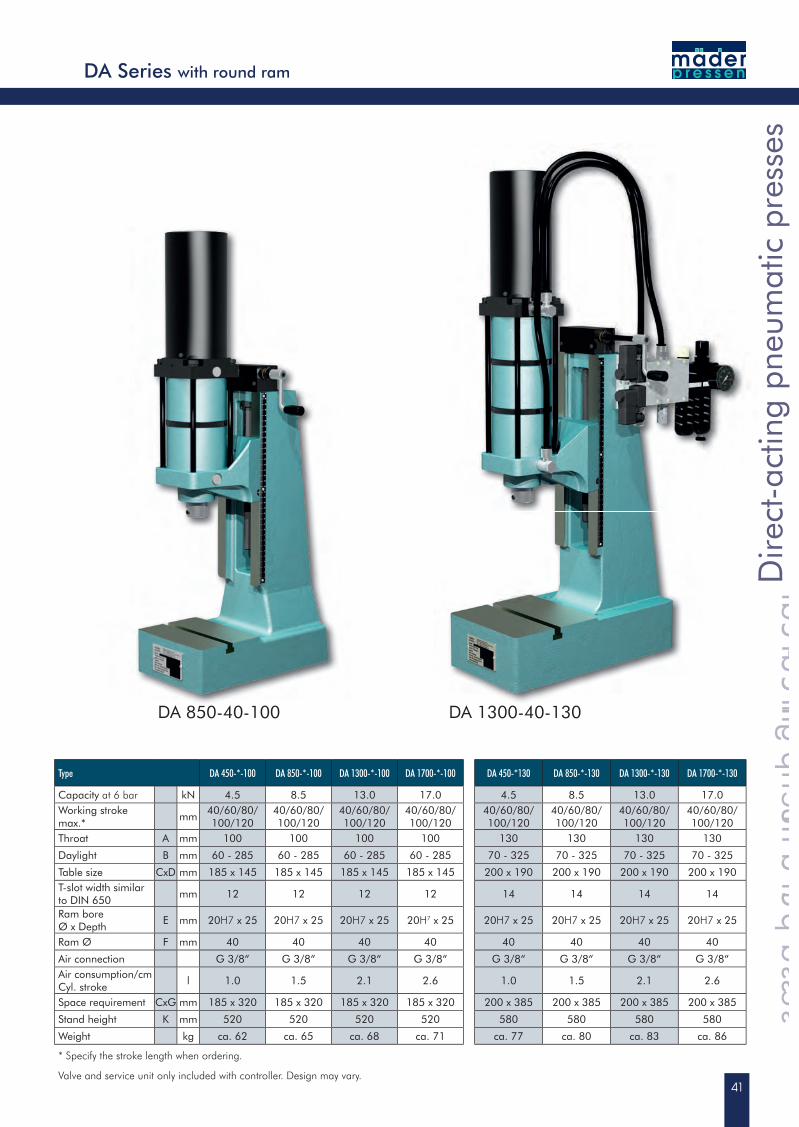
DA 850-40-100
Type DA 450-*-100 DA 850-*-100 DA 1300-*-100 DA 1700-*-100 DA 450-*130 DA 850-*-130 DA 1300-*-130 DA 1700-*-130
Capacity at 6 bar kN 4.5 8.5 13.0 17.0 4.5 8.5 13.0 17.0Working stroke max.*
mm40/60/80/100/120
40/60/80/100/120
40/60/80/100/120
40/60/80/100/120
40/60/80/100/120
40/60/80/100/120
40/60/80/100/120
40/60/80/100/120
Throat A mm 100 100 100 100 130 130 130 130
Daylight B mm 60 - 285 60 - 285 60 - 285 60 - 285 70 - 325 70 - 325 70 - 325 70 - 325
Table size CxD mm 185 x 145 185 x 145 185 x 145 185 x 145 200 x 190 200 x 190 200 x 190 200 x 190T-slot width similarto DIN 650
mm 12 12 12 12 14 14 14 14
Ram bore Ø x Depth
E mm 20H7 x 25 20H7 x 25 20H7 x 25 20H7 x 25 20H7 x 25 20H7 x 25 20H7 x 25 20H7 x 25
Ram Ø F mm 40 40 40 40 40 40 40 40
Air connection G 3/8“ G 3/8“ G 3/8“ G 3/8“ G 3/8“ G 3/8“ G 3/8“ G 3/8“Air consumption/cm Cyl. stroke
l 1.0 1.5 2.1 2.6 1.0 1.5 2.1 2.6
Space requirement CxG mm 185 x 320 185 x 320 185 x 320 185 x 320 200 x 385 200 x 385 200 x 385 200 x 385
Stand height K mm 520 520 520 520 580 580 580 580
Weight kg ca. 62 ca. 65 ca. 68 ca. 71 ca. 77 ca. 80 ca. 83 ca. 86
* Specify the stroke length when ordering.
Valve and service unit only included with controller. Design may vary.
Dire
ct-a
ctin
g pn
eum
atic
pre
sses
Direct-acting pneumatic presses
Direct-acting pneumatic presses
Dire
ct-a
ctin
g pn
eum
atic
pre
sses
Direct-acting pneumatic presses
Dire
ct-a
ctin
g pn
eum
atic
pre
sses
Dire
ct-a
ctin
g pn
eum
atic
pre
sses
Direct-acting pneumatic presses
Dire
ct-a
ctin
g pn
eum
atic
pre
sses
DA 1300-40-130
DA Series with round ram
42
0 kN
5 kN
10 kN
15 kN
20 kN
25 kN
30 kN
35 kN
40 kN
45 kN
0 bar 1 bar 2 bar 3 bar 4 bar 5 bar 6 bar
DA 2100-*-130
DA 2800-*-130
DA 3400-*-130
E
E
B
F
A
G
D C
10
M8
E
K
Request CAD at www.maederpressen.de or directly from Tel.+49 (0)7467-9467-0
Direct-acting pneumatic presses
The accessories
0 kN
5 kN
10 kN
15 kN
20 kN
25 kN
30 kN
35 kN
40 kN
45 kN
0 bar 1 bar 2 bar 3 bar 4 bar 5 bar 6 bar
DA 2100-*-130
DA 2800-*-130
DA 3400-*-130
3.2 bar
E
E
B
F
A
G
D C
10
M8
E
K
For details of fine stroke adjustment see page 37
43
Type DA 2100-*-130 DA 2800-*130 DA 3400-*-130
Capacity at 6 bar kN 21.0 28.0 34.0
Working stroke max.* mm 40/60/80/100/120 40/60/80/100/120 40/60/80/100/120
Throat A mm 130 130 130
Daylight B mm 75 - 330 75 - 330 75 - 330
Table size CxD mm 200 x 190 200 x 190 200 x 190
T-slot width similar to DIN 650 mm 14 14 14
Ram bore Ø x Depth E mm 20H7 x 25 20H7 x 25 20H7 x 25
Ram Ø F mm 40 40 40
Air connection G 3/8“ G 3/8“ G 3/8“
Air consumption/cm cyl. stroke l 3.0 3.7 4.5
Space requirement CxG mm 200 x 385 200 x 385 200 x 385
Stand height K mm 580 580 580
Weight kg ca. 92 ca. 99 ca. 105
* Specify the stroke length when ordering.
Valve and service unit only included with controller. Design may vary.
Dire
ct-a
ctin
g pn
eum
atic
pre
sses
Direct-acting pneumatic presses
Dire
ct-a
ctin
g pn
eum
atic
pre
sses
Direct-acting pneumatic presses
Dire
ct-a
ctin
g pn
eum
atic
pre
sses
DA 3400-40-130
DA Series with round ram
44
E
B
F
A
H
G
C
D
10
E
M8
K
BB
E
0 kN
5 kN
10 kN
15 kN
20 kN
25 kN
0 bar 1 bar 2 bar 3 bar 4 bar 5 bar 6 bar
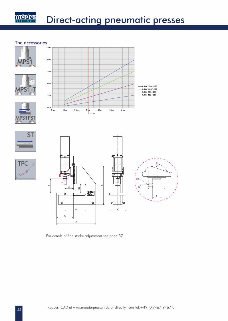
XL-DA 450-*-250
XL-DA 850-*-250
XL-DA 1300-*-250
XL-DA 1700-*-250
Request CAD at www.maederpressen.de or directly from Tel.+49 (0)7467-9467-0
E
B
F
A
H
G
C
D
10
E
M8
K
BB
E
0 kN
5 kN
10 kN
15 kN
20 kN
25 kN
0 bar 1 bar 2 bar 3 bar 4 bar 5 bar 6 bar
XL-DA 450-*-250
XL-DA 850-*-250
XL-DA 1300-*-250
XL-DA 1700-*-250
3.2 bar
The accessories
For details of fine stroke adjustment see page 37
Direct-acting pneumatic presses
45
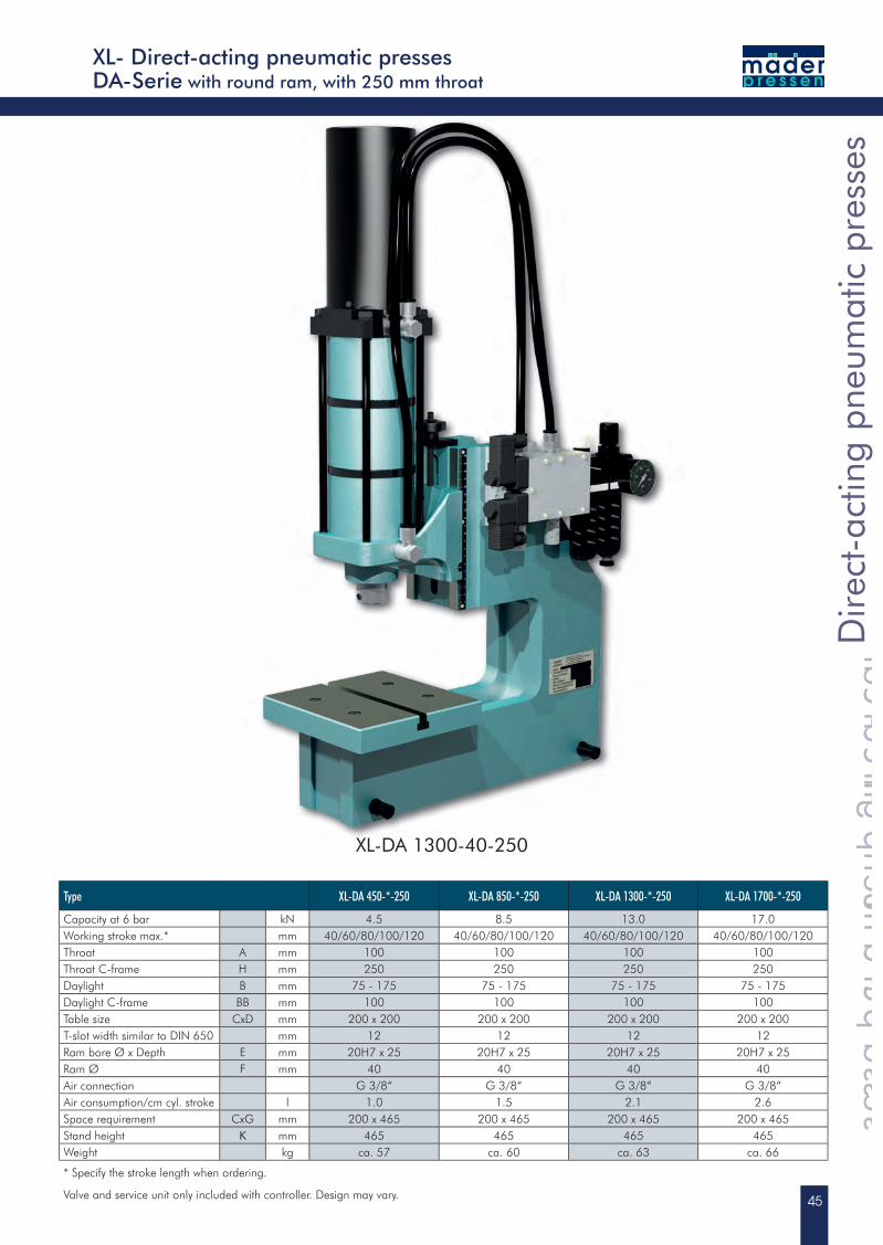
XL-DA 1300-40-250
Type XL-DA 450-*-250 XL-DA 850-*-250 XL-DA 1300-*-250 XL-DA 1700-*-250
Capacity at 6 bar kN 4.5 8.5 13.0 17.0Working stroke max.* mm 40/60/80/100/120 40/60/80/100/120 40/60/80/100/120 40/60/80/100/120Throat A mm 100 100 100 100Throat C-frame H mm 250 250 250 250Daylight B mm 75 - 175 75 - 175 75 - 175 75 - 175Daylight C-frame BB mm 100 100 100 100Table size CxD mm 200 x 200 200 x 200 200 x 200 200 x 200T-slot width similar to DIN 650 mm 12 12 12 12Ram bore Ø x Depth E mm 20H7 x 25 20H7 x 25 20H7 x 25 20H7 x 25Ram Ø F mm 40 40 40 40Air connection G 3/8“ G 3/8“ G 3/8“ G 3/8“Air consumption/cm cyl. stroke l 1.0 1.5 2.1 2.6Space requirement CxG mm 200 x 465 200 x 465 200 x 465 200 x 465Stand height K mm 465 465 465 465Weight kg ca. 57 ca. 60 ca. 63 ca. 66
* Specify the stroke length when ordering.
Valve and service unit only included with controller. Design may vary.
XL- Direct-acting pneumatic pressesDA-Serie with round ram, with 250 mm throat
Dire
ct-a
ctin
g pn
eum
atic
pre
sses
Direct-acting pneumatic presses
Dire
ct-a
ctin
g pn
eum
atic
pre
sses
Direct-acting pneumatic presses
Dire
ct-a
ctin
g pn
eum
atic
pre
sses
46
E
B
A
H
F
D
G
C
10
E
M8
K
BB
E
0 kN
5 kN
10 kN
15 kN
20 kN
25 kN
30 kN
35 kN
40 kN
45 kN
0 bar 1 bar 2 bar 3 bar 4 bar 5 bar 6 bar
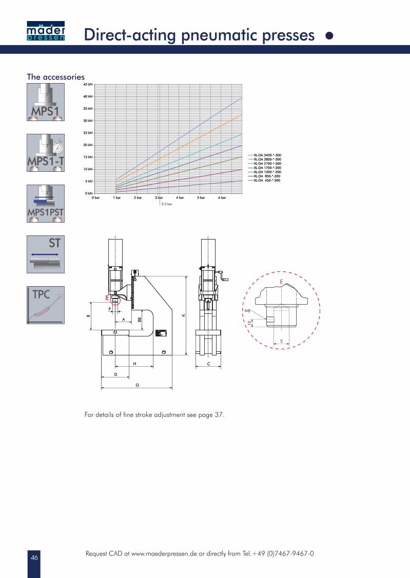
XL-DA 450-*-300XL-DA 850-*-300XL-DA 1300-*-300XL-DA 1700-*-300XL-DA 2100-*-300XL-DA 2800-*-300XL-DA 3400-*-300
Request CAD at www.maederpressen.de or directly from Tel.+49 (0)7467-9467-0
E
B
A
H
F
D
G
C
10
E
M8
K
BB
E
0 kN
5 kN
10 kN
15 kN
20 kN
25 kN
30 kN
35 kN
40 kN
45 kN
0 bar 1 bar 2 bar 3 bar 4 bar 5 bar 6 bar
XL-DA 450-*-300XL-DA 850-*-300XL-DA 1300-*-300XL-DA 1700-*-300XL-DA 2100-*-300XL-DA 2800-*-300XL-DA 3400-*-300
3.2 bar
Direct-acting pneumatic presses
The accessories
For details of fine stroke adjustment see page 37.
47
XL-DA 2800-40-300
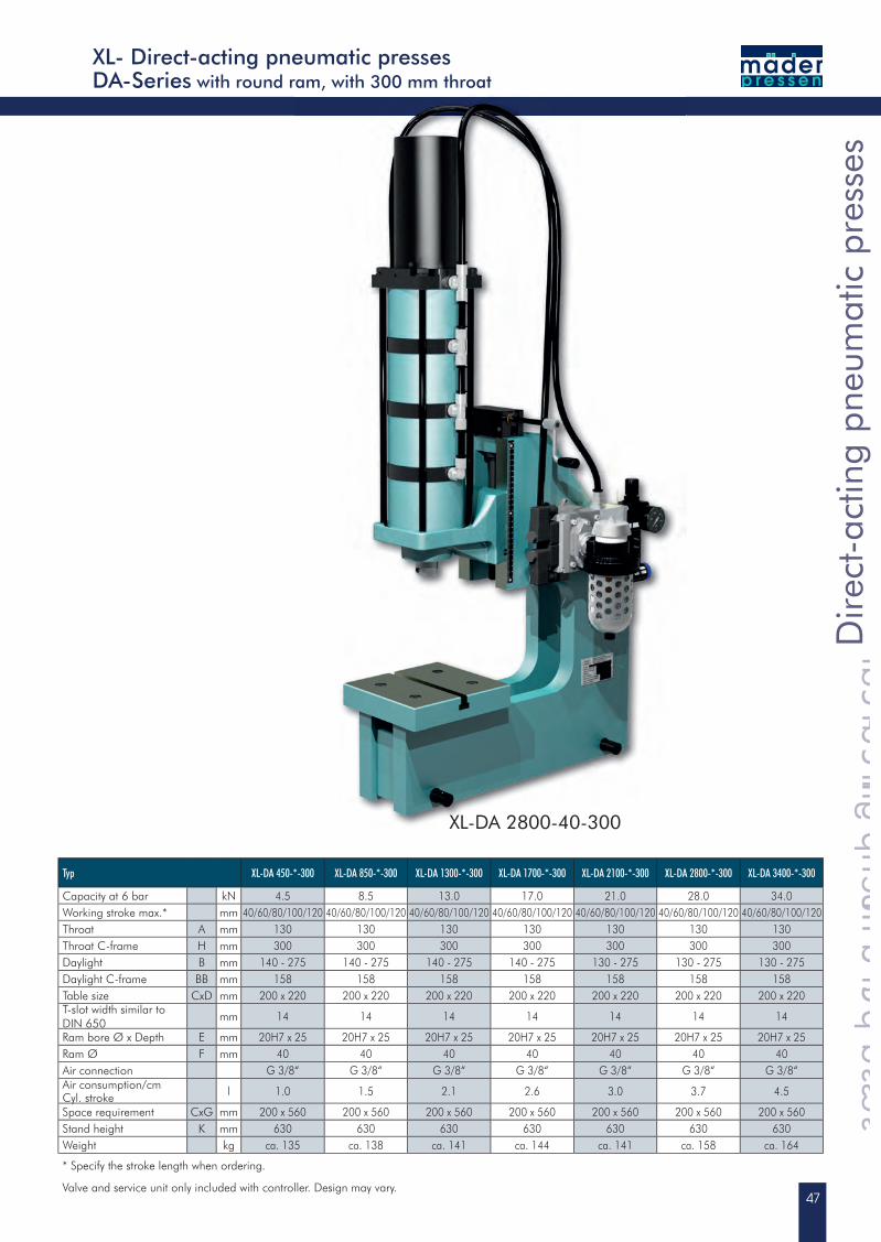
XL- Direct-acting pneumatic pressesDA-Series with round ram, with 300 mm throat
Typ XL-DA 450-*-300 XL-DA 850-*-300 XL-DA 1300-*-300 XL-DA 1700-*-300 XL-DA 2100-*-300 XL-DA 2800-*-300 XL-DA 3400-*-300
Capacity at 6 bar kN 4.5 8.5 13.0 17.0 21.0 28.0 34.0Working stroke max.* mm 40/60/80/100/120 40/60/80/100/120 40/60/80/100/120 40/60/80/100/120 40/60/80/100/120 40/60/80/100/120 40/60/80/100/120Throat A mm 130 130 130 130 130 130 130Throat C-frame H mm 300 300 300 300 300 300 300Daylight B mm 140 - 275 140 - 275 140 - 275 140 - 275 130 - 275 130 - 275 130 - 275Daylight C-frame BB mm 158 158 158 158 158 158 158Table size CxD mm 200 x 220 200 x 220 200 x 220 200 x 220 200 x 220 200 x 220 200 x 220T-slot width similar toDIN 650
mm 14 14 14 14 14 14 14
Ram bore Ø x Depth E mm 20H7 x 25 20H7 x 25 20H7 x 25 20H7 x 25 20H7 x 25 20H7 x 25 20H7 x 25Ram Ø F mm 40 40 40 40 40 40 40Air connection G 3/8“ G 3/8“ G 3/8“ G 3/8“ G 3/8“ G 3/8“ G 3/8“Air consumption/cm Cyl. stroke l 1.0 1.5 2.1 2.6 3.0 3.7 4.5
Space requirement CxG mm 200 x 560 200 x 560 200 x 560 200 x 560 200 x 560 200 x 560 200 x 560Stand height K mm 630 630 630 630 630 630 630Weight kg ca. 135 ca. 138 ca. 141 ca. 144 ca. 141 ca. 158 ca. 164
* Specify the stroke length when ordering.
Valve and service unit only included with controller. Design may vary.
Dire
ct-a
ctin
g pn
eum
atic
pre
sses
Direct-acting pneumatic presses
Dire
ct-a
ctin
g pn
eum
atic
pre
sses
Direct-acting pneumatic presses
Dire
ct-a
ctin
g pn
eum
atic
pre
sses
48
0,0 kN
10,0 kN
20,0 kN
30,0 kN
40,0 kN
50,0 kN
60,0 kN
70,0 kN
0 bar 1 bar 2 bar 3 bar 4 bar 5 bar 6 bar
DA 3300XL-DA 3300
DA 4500XL-DA 4500
DA 5600XL-DA 5600
E
KF
B
G
D
A
C
E
10
M8
E
C
M
Y
CM
MY
CY
CMY
K
Masszeichnung Prospekt DA 3300-40-150.pdf 1 05.09.2013 16:25:33
EK
G
A
H
F
B
BB
L
C
D
10
E
M8
E
a
k
w
ak
kw
aw
akw
i
k ®®µ¤¨¢§«°«¦>n�¬®¤�¯>vjKb_>QQNNKRNKOSNL£¥>>>O>>>NSLNWLPNOQ>>>OTXOUXOU
DA Typ XL-DA Typ
Request CAD at www.maederpressen.de or directly from Tel.+49 (0)7467-9467-0
The accessories
0,0 kN
10,0 kN
20,0 kN
30,0 kN
40,0 kN
50,0 kN
60,0 kN
70,0 kN
0 bar 1 bar 2 bar 3 bar 4 bar 5 bar 6 bar
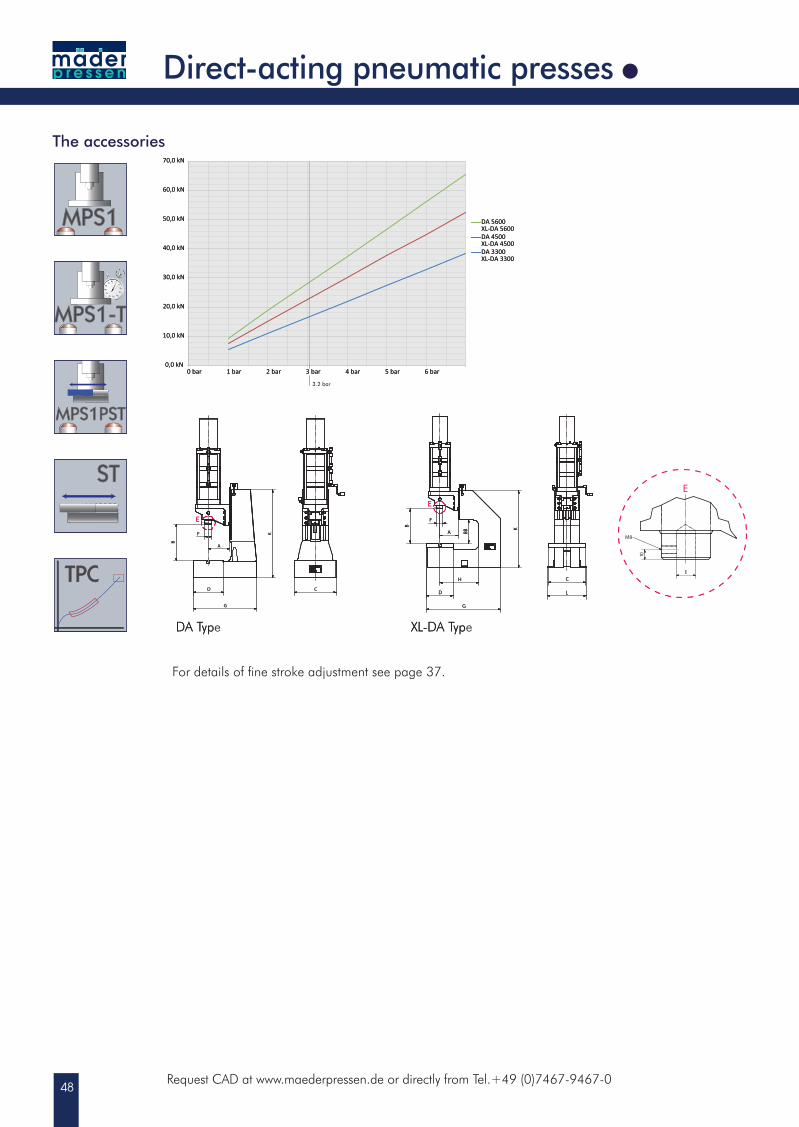
DA 3300XL-DA 3300
DA 4500XL-DA 4500
DA 5600XL-DA 5600
3.2 bar
E
KF
B
G
D
A
C
E
10
M8
E
C
M
Y
CM
MY
CY
CMY
K
Masszeichnung Prospekt DA 3300-40-150.pdf 1 05.09.2013 16:25:33
EK
G
A
H
F
B
BB
L
C
D
10
E
M8
E
a
k
w
ak
kw
aw
akw
i
k ®®µ¤¨¢§«°«¦>n�¬®¤�¯>vjKb_>QQNNKRNKOSNL£¥>>>O>>>NSLNWLPNOQ>>>OTXOUXOU
DA Type XL-DA Type
Direct-acting pneumatic presses
For details of fine stroke adjustment see page 37.
49
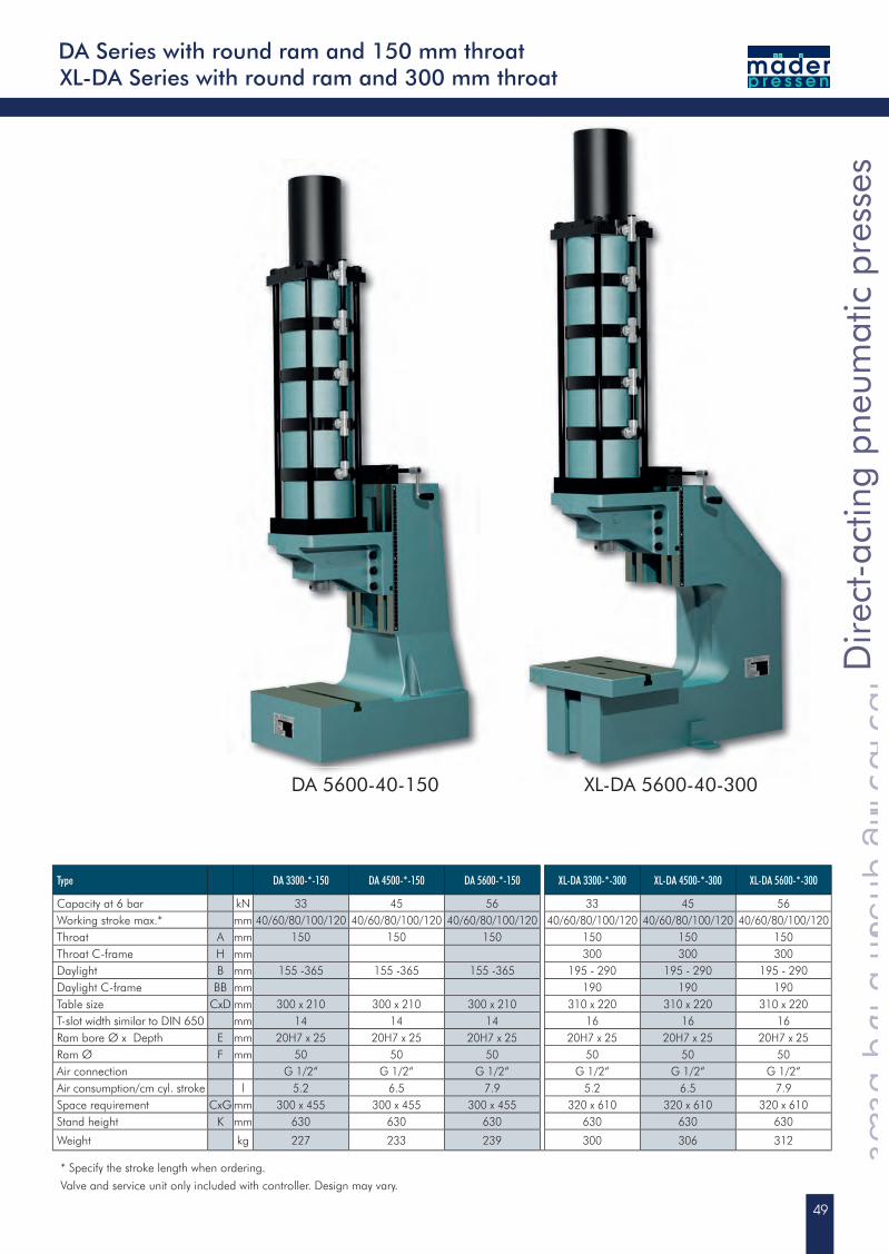
XL-DA Series with round ram and 300 mm throatDA Series with round ram and 150 mm throat
* Specify the stroke length when ordering.
Valve and service unit only included with controller. Design may vary.
Dire
ct-a
ctin
g pn
eum
atic
pre
sses
Direct-acting pneumatic presses
Dire
ct-a
ctin
g pn
eum
atic
pre
sses
Direct-acting pneumatic presses
Dire
ct-a
ctin
g pn
eum
atic
pre
sses
Type DA 3300-*-150 DA 4500-*-150 DA 5600-*-150 XL-DA 3300-*-300 XL-DA 4500-*-300 XL-DA 5600-*-300
Capacity at 6 bar kN 33 45 56 33 45 56Working stroke max.* mm 40/60/80/100/120 40/60/80/100/120 40/60/80/100/120 40/60/80/100/120 40/60/80/100/120 40/60/80/100/120Throat A mm 150 150 150 150 150 150Throat C-frame H mm 300 300 300Daylight B mm 155 -365 155 -365 155 -365 195 - 290 195 - 290 195 - 290Daylight C-frame BB mm 190 190 190Table size CxD mm 300 x 210 300 x 210 300 x 210 310 x 220 310 x 220 310 x 220T-slot width similar to DIN 650 mm 14 14 14 16 16 16Ram bore Ø x Depth E mm 20H7 x 25 20H7 x 25 20H7 x 25 20H7 x 25 20H7 x 25 20H7 x 25Ram Ø F mm 50 50 50 50 50 50Air connection G 1/2“ G 1/2“ G 1/2“ G 1/2“ G 1/2“ G 1/2“Air consumption/cm cyl. stroke l 5.2 6.5 7.9 5.2 6.5 7.9Space requirement CxG mm 300 x 455 300 x 455 300 x 455 320 x 610 320 x 610 320 x 610Stand height K mm 630 630 630 630 630 630
Weight kg 227 233 239 300 306 312
XL-DA 5600-40-300DA 5600-40-150
50
0 kN
5 kN
10 kN
15 kN
20 kN
25 kN
30 kN
35 kN
40 kN
0 bar 1 bar 2 bar 3 bar 4 bar 5 bar 6 bar
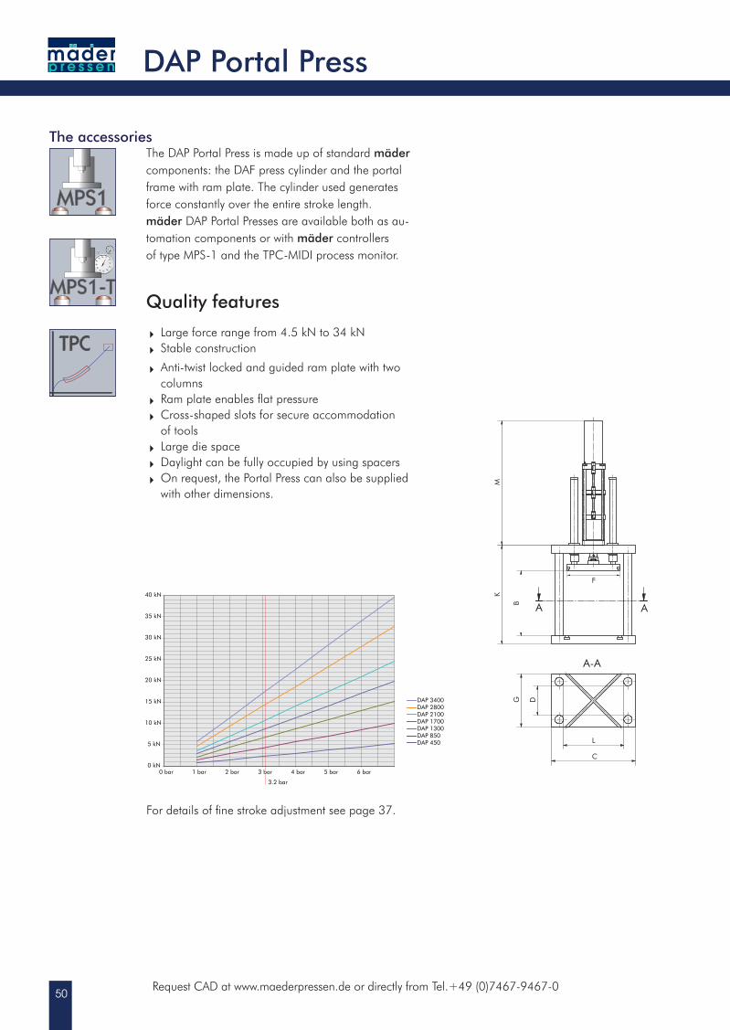
DAP 450DAP 850DAP 1300DAP 1700DAP 2100DAP 2800DAP 3400
3.2 bar
A-A
A A
G
C
K
B
D
L
M
F
Request CAD at www.maederpressen.de or directly from Tel.+49 (0)7467-9467-0
DAP Portal Press
The accessories
For details of fine stroke adjustment see page 37.
The DAP Portal Press is made up of standard mäder components: the DAF press cylinder and the portal frame with ram plate. The cylinder used generates force constantly over the entire stroke length. mäder DAP Portal Presses are available both as au-tomation components or with mäder controllers of type MPS-1 and the TPC-MIDI process monitor.
Quality features
Large force range from 4.5 kN to 34 kN Stable construction
Anti-twist locked and guided ram plate with two columns Ram plate enables flat pressure Cross-shaped slots for secure accommodation of tools Large die space Daylight can be fully occupied by using spacers On request, the Portal Press can also be supplied
with other dimensions.
51
DA
P Po
rtal P
ress
DAP Portal Press
DA
P Po
rtal P
ress
DAP Portal Press
DA
P Po
rtal P
ress
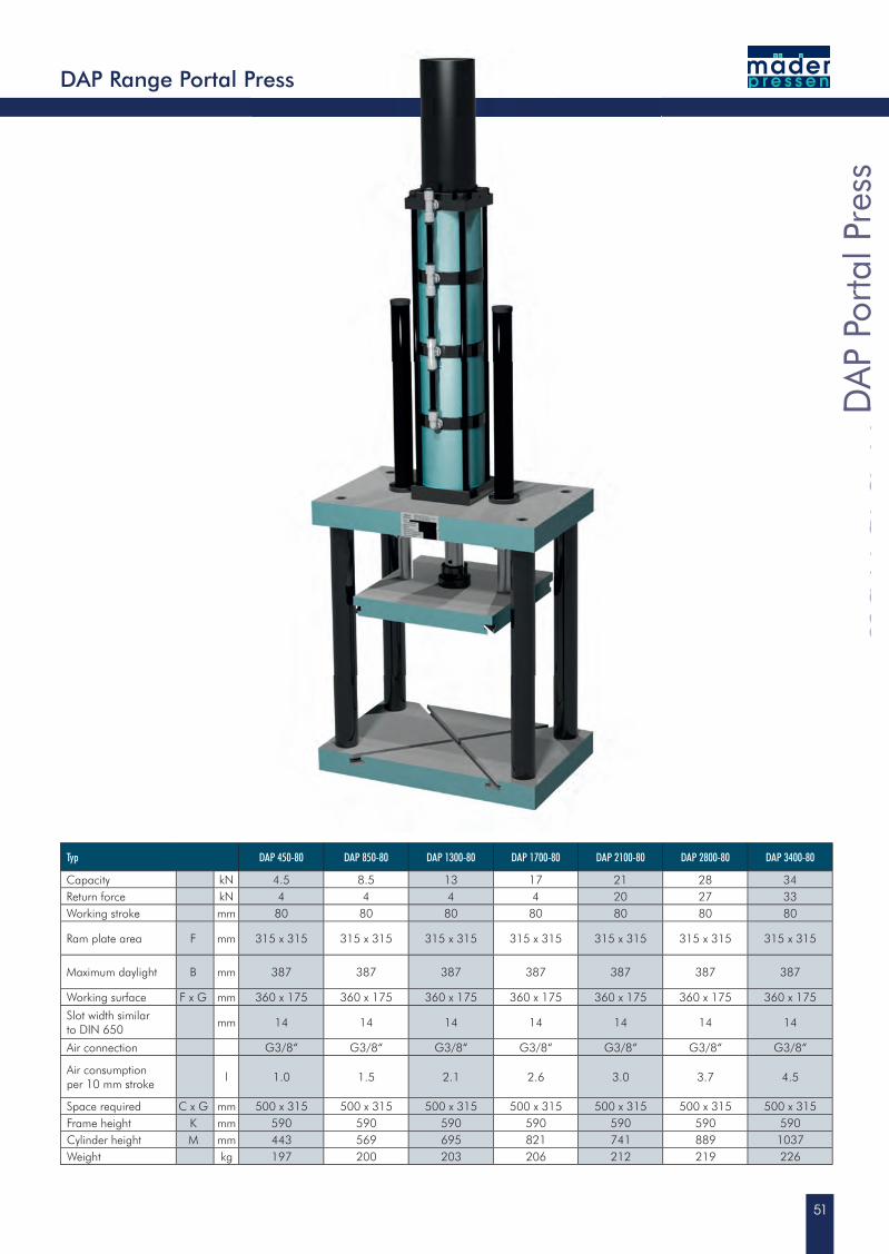
DAP Range Portal Press
Typ DAP 450-80 DAP 850-80 DAP 1300-80 DAP 1700-80 DAP 2100-80 DAP 2800-80 DAP 3400-80
Capacity kN 4.5 8.5 13 17 21 28 34Return force kN 4 4 4 4 20 27 33Working stroke mm 80 80 80 80 80 80 80
Ram plate area F mm 315 x 315 315 x 315 315 x 315 315 x 315 315 x 315 315 x 315 315 x 315
Maximum daylight B mm 387 387 387 387 387 387 387
Working surface F x G mm 360 x 175 360 x 175 360 x 175 360 x 175 360 x 175 360 x 175 360 x 175
Slot width similar to DIN 650
mm 14 14 14 14 14 14 14
Air connection G3/8“ G3/8“ G3/8“ G3/8“ G3/8“ G3/8“ G3/8“
Air consumption per 10 mm stroke
l 1.0 1.5 2.1 2.6 3.0 3.7 4.5
Space required C x G mm 500 x 315 500 x 315 500 x 315 500 x 315 500 x 315 500 x 315 500 x 315Frame height K mm 590 590 590 590 590 590 590Cylinder height M mm 443 569 695 821 741 889 1037Weight kg 197 200 203 206 212 219 226
52
30 kN
40 kN
50 kN
60 kN
70 kN
10 kN
20 kN
0 bar 1 bar 2 bar 3 bar 4 bar 5 bar 6 bar 7 bar
DAF 450DAF 850DAF 1300DAF 1700
DAF 2100
DAF 2800DAF 3300DAF 3400DAF 4500DAF 5600
3.2 bar
E
A
B
B
Ø 40
22C
42,4
4
24,5
49
6xM10
Ø 70f7
10
25
M8
Ø 20H7
E
E
A
B
B
Ø 40
22C
42,4
4
24,5
49
6xM10
Ø 70f7
10
25
M8
Ø 20H7
E
E ( 1 : 1 )
E
A
B
B
Ø 40
70Ø f7
22C
20Ø H7
10
25
M8
6xM1098LK Ø
E
E
B
B
6xM10
98LK Ø
Ø40
Ø70f7
C22
A
30
10
Ø 20H7
M8
E
E
B
B
6xM10
98LK Ø
Ø40
Ø70f7
C22
A
30
10
Ø 20H7
M8
E
1
1
2
2
3
3
4
4
5
5
6
6
7
7
8
8
9
9
10
10
A A
B B
C C
D D
E E
F F
Zust . Änderungen Datum Name
Datum NameBearb.Gepr.
Modell
Maßst ab
Ersat z für Erset zt durch
Blat t
Ursprung
ENG-004059Z2
Maßzeichnung DAF Pressenkopf 5600-40Prospekt
23.09.2014 Finst erle
Finst erle01.07.2008
1
A3
Kom.Nr.
Kd.Nr.
Diese Zeichnung darf ohne unsereGenehmigung weder vervielfältigt, nochd r i t t e n P e r s o n e n zugeleitetwerden. (§ 18 des Unl.WG., 8.6.1909)
1:4 /(1:4),(1:1,5)
Posit ion Menge
Zeichnungsnummer
Benennung
maederpressen GmbHR obert-Boschs tr.1378579 Neuhausen ob Eck
5-256-04-0010Artikel-Nr.
AllgemeintoleranzenDIN ISO2768-1mForm- und LagetoleranzenDIN ISO2768-2H
E
A22
C
ø50
ø70f7
B
B
98LK ø
6 x M10
10
20ø H7
30
M8
E
1
1
2
2
3
3
4
4
5
5
6
6
7
7
8
8
9
9
10
10
A A
B B
C C
D D
E E
F F
Zust . Änderungen Datum Name
Datum NameBearb.Gepr.
Modell
Maßst ab
Ersat z für Erset zt durch
Blat t
Ursprung
ENG-004059Z2
Maßzeichnung DAF Pressenkopf 5600-40Prospekt
23.09.2014 Finst erle
Finst erle01.07.2008
1
A3
Kom.Nr.
Kd.Nr.
Diese Zeichnung darf ohne unsereGenehmigung weder vervielfältigt, nochd r i t t e n P e r s o n e n zugeleitetwerden. (§ 18 des Unl.WG., 8.6.1909)
1:4 /(1:4),(1:1,5)
Posit ion Menge
Zeichnungsnummer
Benennung
maederpressen GmbHR obert-Boschs tr.1378579 Neuhausen ob Eck
5-256-04-0010Artikel-Nr.
AllgemeintoleranzenDIN ISO2768-1mForm- und LagetoleranzenDIN ISO2768-2H
E
A22
C
ø50
ø70f7
B
B
98LK ø
6 x M1010
20ø H7
30
M8
E
1
1
2
2
3
3
4
4
5
5
6
6
7
7
8
8
9
9
10
10
A A
B B
C C
D D
E E
F F
Zust . Änderungen Datum Name
Datum NameBearb.Gepr.
Modell
Maßst ab
Ersat z für Erset zt durch
Blat t
Ursprung
ENG-004059Z2
Maßzeichnung DAF Pressenkopf 5600-40Prospekt
23.09.2014 Finst erle
Finst erle01.07.2008
1
A3
Kom.Nr.
Kd.Nr.
Diese Zeichnung darf ohne unsereGenehmigung weder vervielfältigt, nochd r i t t e n P e r s o n e n zugeleitetwerden. (§ 18 des Unl.WG., 8.6.1909)
1:4 /(1:4),(1:1,5)
Posit ion Menge
Zeichnungsnummer
Benennung
maederpressen GmbHR obert-Boschs tr.1378579 Neuhausen ob Eck
5-256-04-0010Artikel-Nr.
AllgemeintoleranzenDIN ISO2768-1mForm- und LagetoleranzenDIN ISO2768-2H
E
A22
C
ø50
ø70f7
B
B
98LK ø
6 x M10
10
20ø H7
30
M8
Request CAD at www.maederpressen.de or directly from Tel.+49 (0)7467-9467-0
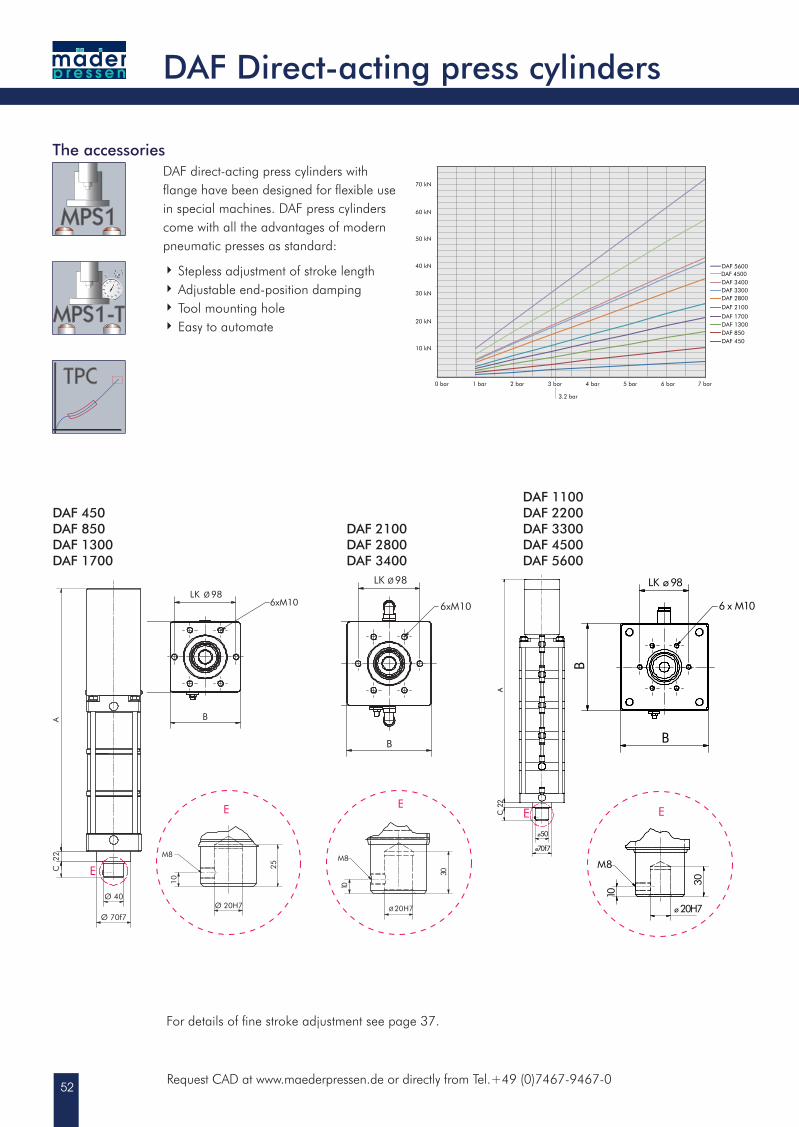
DAF direct-acting press cylinders with fl ange have been designed for fl exible use in special machines. DAF press cylinders come with all the advantages of modern pneumatic presses as standard:
Stepless adjustment of stroke length Adjustable end-position damping Tool mounting hole Easy to automate
DAF Direct-acting press cylinders
The accessories
For details of fi ne stroke adjustment see page 37.
DAF 450DAF 850DAF 1300 DAF 1700
DAF 2100DAF 2800DAF 3400
DAF 1100DAF 2200DAF 3300DAF 4500DAF 5600
53
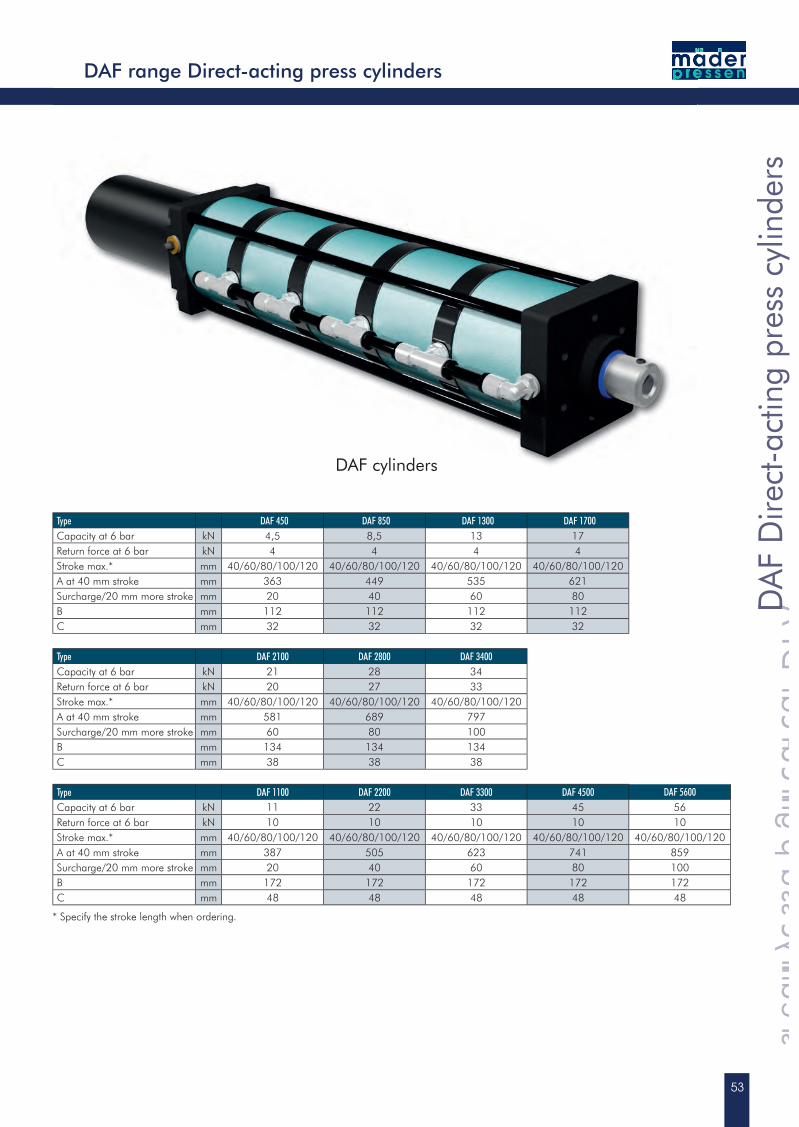
DAF cylinders
DA
F D
irect
-act
ing
pres
s cy
linde
rs
DAF Direct-acting press cylinders
DA
F D
irect
-act
ing
pres
s cy
linde
rs
DAF Direct-acting press cylinders
DA
F D
irect
-act
ing
pres
s cy
linde
rs
DAF range Direct-acting press cylinders
* Specify the stroke length when ordering.
Type DAF 450 DAF 850 DAF 1300 DAF 1700Capacity at 6 bar kN 4,5 8,5 13 17Return force at 6 bar kN 4 4 4 4Stroke max.* mm 40/60/80/100/120 40/60/80/100/120 40/60/80/100/120 40/60/80/100/120A at 40 mm stroke mm 363 449 535 621Surcharge/20 mm more stroke mm 20 40 60 80B mm 112 112 112 112C mm 32 32 32 32
Type DAF 2100 DAF 2800 DAF 3400Capacity at 6 bar kN 21 28 34Return force at 6 bar kN 20 27 33Stroke max.* mm 40/60/80/100/120 40/60/80/100/120 40/60/80/100/120A at 40 mm stroke mm 581 689 797Surcharge/20 mm more stroke mm 60 80 100B mm 134 134 134C mm 38 38 38
Type DAF 1100 DAF 2200 DAF 3300 DAF 4500 DAF 5600Capacity at 6 bar kN 11 22 33 45 56Return force at 6 bar kN 10 10 10 10 10Stroke max.* mm 40/60/80/100/120 40/60/80/100/120 40/60/80/100/120 40/60/80/100/120 40/60/80/100/120A at 40 mm stroke mm 387 505 623 741 859Surcharge/20 mm more stroke mm 20 40 60 80 100B mm 172 172 172 172 172C mm 48 48 48 48 48
54
E
B
A
G
D C
F
K
8
M6
E
E
0 N
100 N
200 N
300 N
400 N
500 N
600 N
700 N
800 N
900 N
1 bar 2 bar 3 bar 4 bar 5 bar 6 bar 7 bar 8 bar
MP 30-60-63
MP 40-60-63
MP 70-60-63
MP 120-60-63
MP 190-60-63
MP 290-60-63
MP 480-60-63
MP 750-60-63
Request CAD at www.maederpressen.de or directly from Tel.+49 (0)7467-9467-0
E
B
A
G
D C
F
K
8
M6
E
E
MicroPress® with square ram
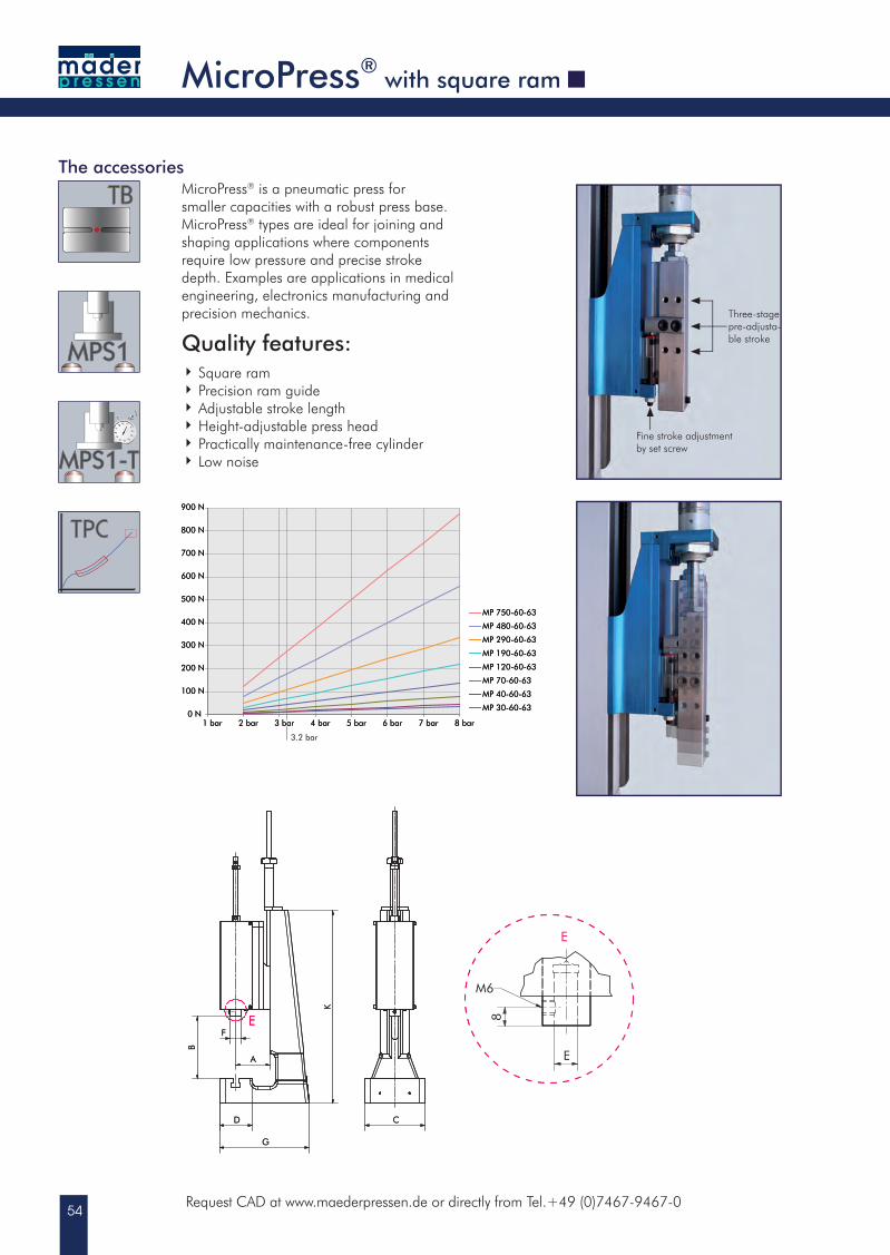
The accessoriesMicroPress® is a pneumatic press for smaller capacities with a robust press base. MicroPress® types are ideal for joining and shaping applications where components require low pressure and precise stroke depth. Examples are applications in medical engineering, electronics manufacturing and precision mechanics.
Quality features: Square ram Precision ram guide Adjustable stroke length Height-adjustable press head Practically maintenance-free cylinder Low noise
0 N
100 N
200 N
300 N
400 N
500 N
600 N
700 N
800 N
900 N
1 bar 2 bar 3 bar 4 bar 5 bar 6 bar 7 bar 8 bar
MP 30-60-63
MP 40-60-63
MP 70-60-63
MP 120-60-63
MP 190-60-63
MP 290-60-63
MP 480-60-63
MP 750-60-63
3.2 bar
Fine stroke adjustment by set screw
Three-stage pre-adjusta-ble stroke
55
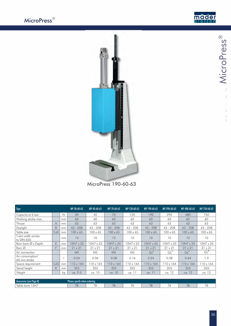
MicroPress 190-60-63
Mic
roPr
ess®
MicroPress
Mic
roPr
ess
MicroPress
Mic
roPr
ess
®
Type MP 30-60-63 MP 40-60-63 MP 70-60-63 MP 120-60-63 MP 190-60-63 MP 290-60-63 MP 480-60-63 MP 750-60-63
Capacity at 6 bar N 30 40 70 120 190 290 480 750Working stroke max. mm 60 60 60 60 60 60 60 60Throat A mm 63 63 63 63 63 63 63 63Daylight B mm 43 - 208 43 - 208 43 - 208 43 - 208 43 - 208 43 - 208 43 - 208 43 - 208Table size CxD mm 100 x 65 100 x 65 100 x 65 100 x 65 100 x 65 100 x 65 100 x 65 100 x 65T-slot width similarto DIN 650
mm 10 10 10 10 10 10 10 10
Ram bore Ø x Depth E mm 10H7 x 25 10H7 x 25 10H7 x 25 10H7 x 25 10H7 x 25 10H7 x 25 10H7 x 25 10H7 x 25Ram Ø F mm 21 x 21 21 x 21 21 x 21 21 x 21 21 x 21 21 x 21 21 x 21 21 x 21Air connection M5 M5 M5 M5Air consumption/60 mm stroke
l 0.04 0.06 0.08 0.16 0.24 0.38 0.64 1.0
Space requirement CxG mm 110 x 164 110 x 164 110 x 164 110 x 164 110 x 164 110 x 164 110 x 164 110 x 164Stand height K mm 355 355 355 355 355 355 355 355Weight kg ca. 9.5 ca. 10 ca. 10 ca. 11 ca. 11 ca. 12 ca. 12 ca. 12
Accessories (see Page 8) Please specify when ordering.Table bore 12H7 TB TB TB TB TB TB TB TB
MicroPress®
G “-81 G “-8
1G “-81 G “-4“1
56Request CAD at www.maederpressen.de or directly from Tel.+49 (0)7467-9467-0
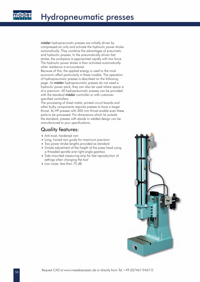
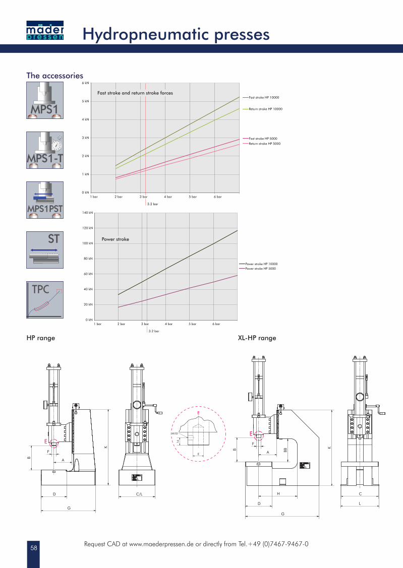
mäder hydropneumatic presses are initially driven by compressed air only and activate the hydraulic power stroke automatically. They combine the advantages of pneumatic and hydraulic presses. In the pneumatically driven fast stroke, the workpiece is approached rapidly with low force. The hydraulic power stroke is then activated automatically when resistance is encountered. Because of this, the applied energy is used to the most economic effect particularly in these models. The operation of hydropneumatic presses is described on the following page. As mäder hydropneumatic presses do not need a hydraulic power pack, they can also be used where space is at a premium. All hydropneumatic presses can be provided with the standard mäder controller or with customer-specifi ed controllers.The processing of sheet metal, printed circuit boards and other bulky components requires presses to have a larger throat. XL-HP presses with 300 mm throat enable even these parts to be processed. For dimensions which lie outside the standard, presses with stands in welded design can be manufactured to your specifi cations.
Quality features: Anti-twist, hardened ram Long, honed ram guide for maximum precision Two power stroke lengths provided as standard Simple adjustment of the height of the press head using a threaded spindle and right-angle gearbox Side-mounted measuring strip for fast reproduction of settings when changing the tool Low noise: less than 75 dB
Hydropneumatic presses
A
B
C
1
2
6
4
5
3
57
Hydropneumatic pressesHP range
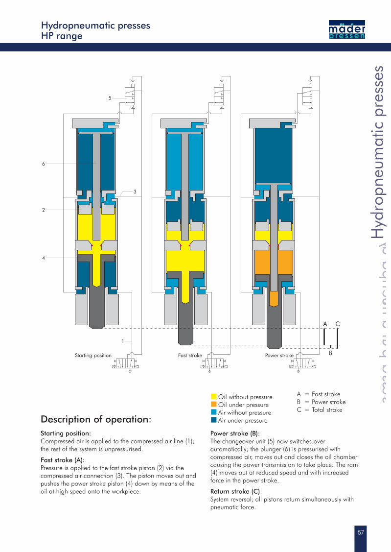
Starting position Fast stroke Power stroke
Hyd
ropn
eum
atic
pre
sses
Hydropneumatic presses
Hyd
ropn
eum
atic
pre
sses
Hydropneumatic presses
Hyd
ropn
eum
atic
pre
sses
Description of operation:Starting position:Compressed air is applied to the compressed air line (1); the rest of the system is unpressurised.
Fast stroke (A):Pressure is applied to the fast stroke piston (2) via the compressed air connection (3). The piston moves out and pushes the power stroke piston (4) down by means of the oil at high speed onto the workpiece.
Oil without pressure Oil under pressure Air without pressure Air under pressure
Power stroke (B):The changeover unit (5) now switches over automatically; the plunger (6) is pressurised with compressed air, moves out and closes the oil chamber causing the power transmission to take place. The ram (4) moves out at reduced speed and with increasedforce in the power stroke.
Return stroke (C):System reversal; all pistons return simultaneously with pneumatic force.
A = Fast stroke B = Power strokeC = Total stroke
58
0 kN
1 kN
2 kN
3 kN
4 kN
5 kN
6 kN
1 bar 2 bar 3 bar 4 bar 5 bar 6 bar
3.2 bar
Eilhub HP 5000
Rückhub HP 5000
Eilhub HP 10000
Rückhub HP 10000
E
K
A
F
G
D
B
C/L
E
14
M10
E
E
12
E
M10
HP 3000
E
B
A
F
H
D
G
K
L
BB
C
0 kN
20 kN
40 kN
60 kN
80 kN
100 kN
120 kN
140 kN
1 bar 2 bar 3 bar 4 bar 5 bar 6 bar
3.2 bar
Krafthub HP 10000Krafthub HP 5000
Eil- und Rückhubkräfte
Krafthub
E
K
A
F
G
D
B
C/L
E
14
M10
E
E
12
E
M10
HP 3000
Request CAD at www.maederpressen.de or directly from Tel.+49 (0)7467-9467-0
Hydropneumatic presses
The accessories
0 kN
1 kN
2 kN
3 kN
4 kN
5 kN
6 kN
1 bar 2 bar 3 bar 4 bar 5 bar 6 bar
Fast stroke HP 5000
Return stroke HP 5000
Return stroke HP 3000
Fast stroke HP 10000
Return stroke HP 10000
HP range XL-HP range
0 kN
20 kN
40 kN
60 kN
80 kN
100 kN
120 kN
140 kN
1 bar 2 bar 3 bar 4 bar 5 bar 6 bar
Power stroke HP 10000
Power stroke HP 3000Power stroke HP 5000
Fast stroke and return stroke forces
Power stroke
59
Hyd
ropn
eum
atic
pre
sses
Hydropneumatic presses
Hyd
ropn
eum
atic
pre
sses
Hydropneumatic presses
Hyd
ropn
eum
atic
pre
sses
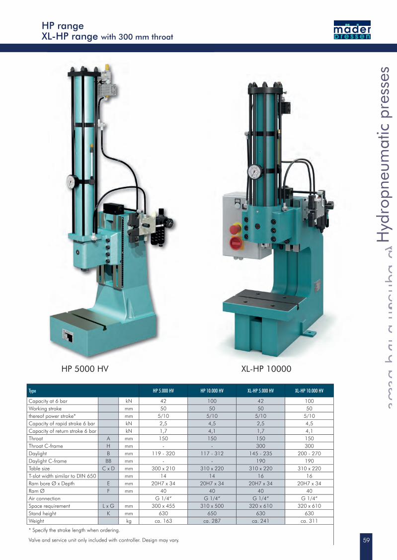
Type HP 5.000 HV HP 10.000 HV XL-HP 5.000 HV XL-HP 10.000 HV
Capacity at 6 bar kN 42 100 42 100Working stroke mm 50 50 50 50thereof power stroke* mm 5/10 5/10 5/10 5/10Capacity of rapid stroke 6 bar kN 2,5 4,5 2,5 4,5Capacity of return stroke 6 bar kN 1,7 4,1 1,7 4,1Throat A mm 150 150 150 150Throat C-frame H mm - - 300 300Daylight B mm 119 - 320 117 - 312 145 - 235 200 - 270Daylight C-frame BB mm - - 190 190Table size C x D mm 300 x 210 310 x 220 310 x 220 310 x 220T-slot width similar to DIN 650 mm 14 14 16 16Ram bore Ø x Depth E mm 20H7 x 34 20H7 x 34 20H7 x 34 20H7 x 34Ram Ø F mm 40 40 40 40Air connection G 1/4“ G 1/4“ G 1/4“ G 1/4“Space requirement L x G mm 300 x 455 310 x 500 320 x 610 320 x 610Stand height K mm 630 650 630 630Weight kg ca. 163 ca. 287 ca. 241 ca. 311
* Specify the stroke length when ordering.
Valve and service unit only included with controller. Design may vary.
HP rangeXL-HP range with 300 mm throat
HP 5000 HV XL-HP 10000
60
5837~
90~
110
150
7590~
150
35~
200
200
(Hub
130
)~
7051
~55
~80 192
200
(Hub
130
)
194
~70
55
Request CAD at www.maederpressen.de or directly from Tel.+49 (0)7467-9467-0
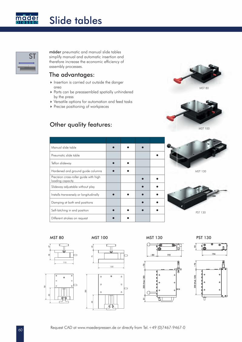
mäder pneumatic and manual slide tables simplify manual and automatic insertion and therefore increase the economic effi ciency ofassembly processes.
The advantages: Insertion is carried out outside the danger area Parts can be preassembled spatially unhindered by the press Versatile options for automation and feed tasks Precise positioning of workpieces
200
(Hub
130
)~
7051
~55
~80 192
MST 130
200
(Hub
130
)
194
~70
55
PST 130
Slide tables
Other quality features:
Manual slide table • • •Pneumatic slide table •Tefl on slideway • •Hardened and ground guide columns • •Precision cross-roller guide with high loading capacity • •Slideway adjustable without play • •Installs transversely or longitudinally • • • •Damping at both end positions • •Self-latching in end position • • • •Different strokes on request • •
MST 80 MST 100
MST 80 MST 100
MST 80
MST 130
PST 130
MST 100
61
Type MST 80 MST 100 MST 130 PST 130
Stroke mm 80 100 130 130Load capacity kN 12 30 50 50Suitable for presses with throat mm 63/80 80/100 100/130/150/250/300 100/130/150/250/300
Slid
e ta
bles
Slide tables
Slid
e ta
bles
Slide tables
Slid
e ta
bles
Slide tables
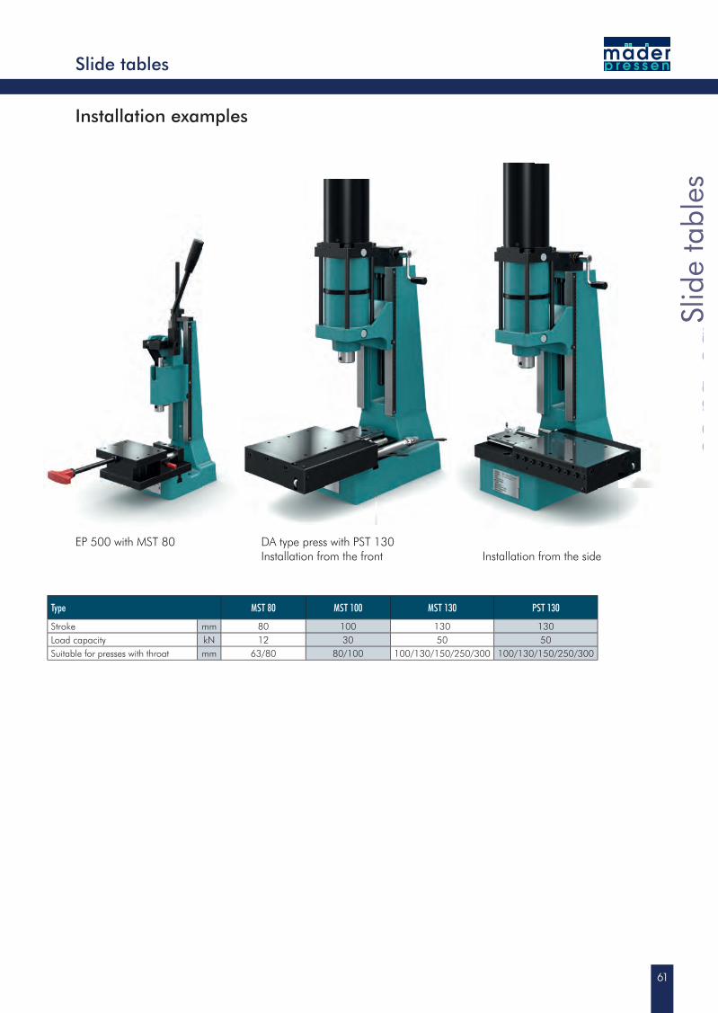
EP 500 with MST 80 DA type press with PST 130Installation from the front Installation from the side
Installation examples
62
96
120~
100
10 H
7
40~
Ø250
Ø200
425~
62
20
50
Ø10 H7
Request CAD at www.maederpressen.de or directly from Tel.+49 (0)7467-9467-0
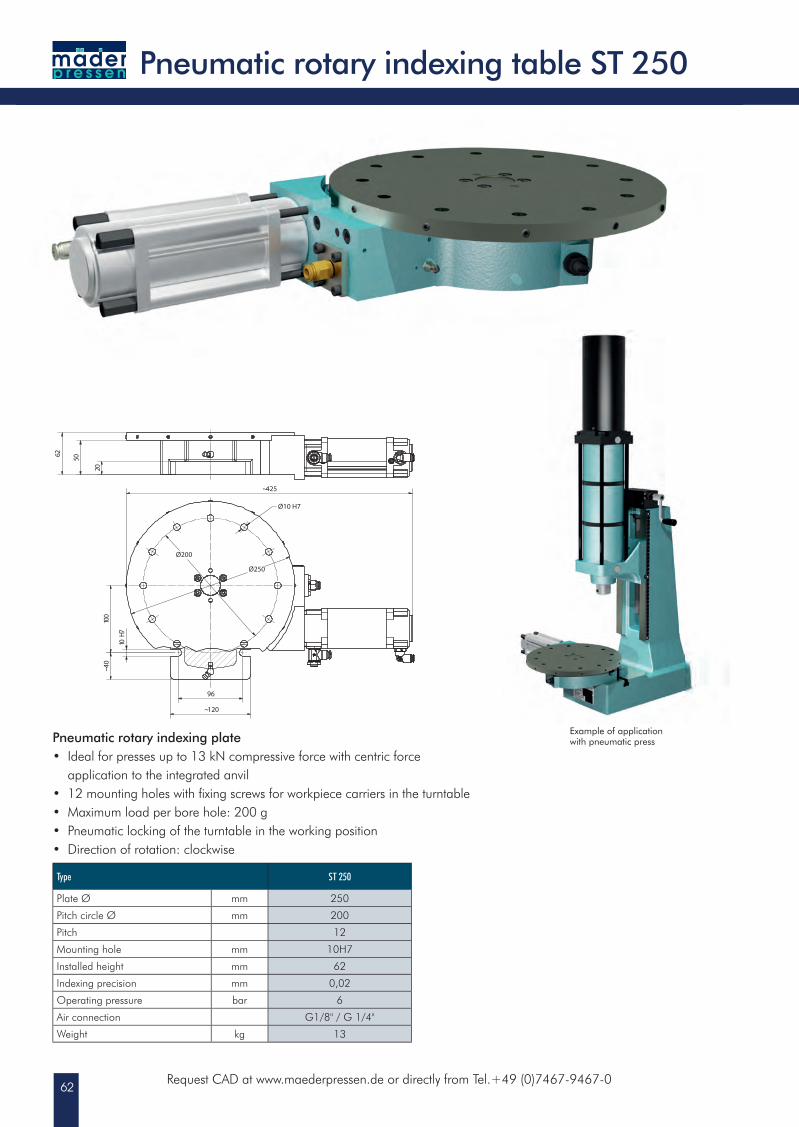
Pneumatic rotary indexing table ST 250
Type ST 250
Plate Ø mm 250
Pitch circle Ø mm 200
Pitch 12
Mounting hole mm 10H7
Installed height mm 62
Indexing precision mm 0,02
Operating pressure bar 6
Air connection G1/8" / G 1/4"
Weight kg 13
Example of application with pneumatic pressPneumatic rotary indexing plate
• Ideal for presses up to 13 kN compressive force with centric force application to the integrated anvil• 12 mounting holes with fi xing screws for workpiece carriers in the turntable• Maximum load per bore hole: 200 g• Pneumatic locking of the turntable in the working position• Direction of rotation: clockwise
63
Pres
s co
ntro
llers
Press controllers
Pres
s co
ntro
llers
Press controllers
Pres
s co
ntro
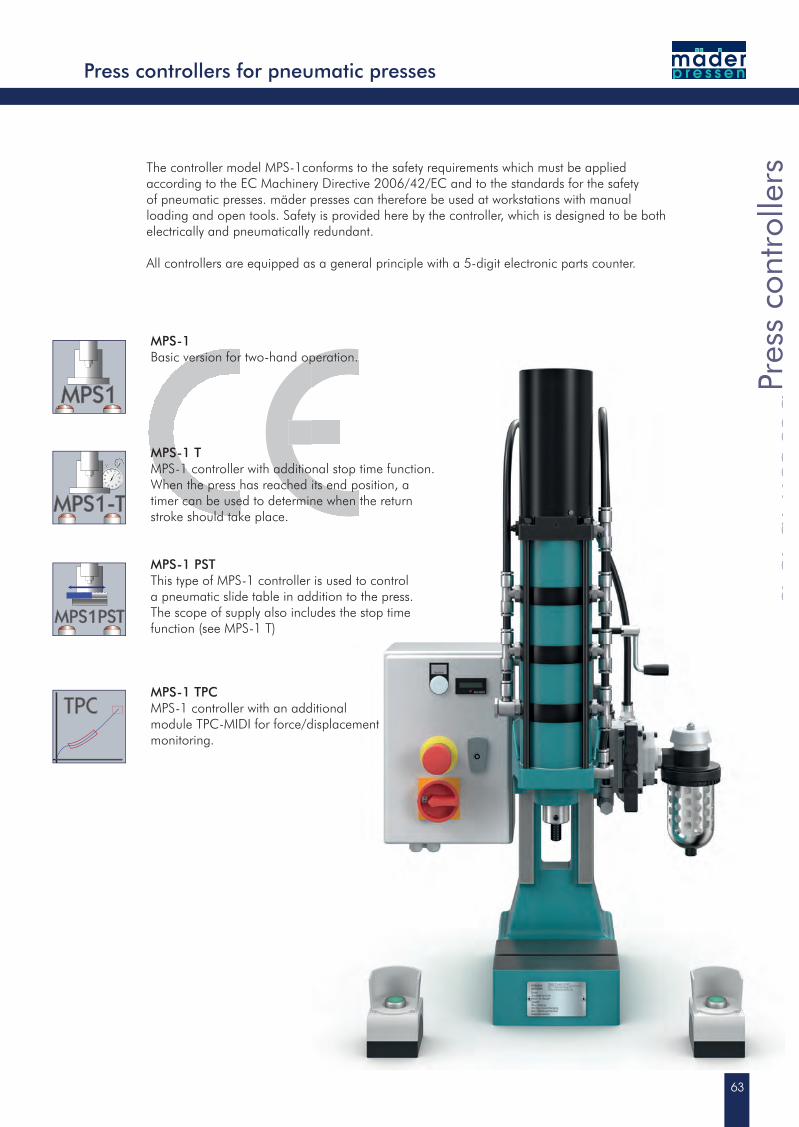
llersThe controller model MPS-1conforms to the safety requirements which must be applied
according to the EC Machinery Directive 2006/42/EC and to the standards for the safety of pneumatic presses. mäder presses can therefore be used at workstations with manual loading and open tools. Safety is provided here by the controller, which is designed to be both electrically and pneumatically redundant.
All controllers are equipped as a general principle with a 5-digit electronic parts counter.
Press controllers for pneumatic presses
MPS-1Basic version for two-hand operation.
MPS-1 TMPS-1 controller with additional stop time function. When the press has reached its end position, a timer can be used to determine when the return stroke should take place.
MPS-1 PSTThis type of MPS-1 controller is used to control a pneumatic slide table in addition to the press. The scope of supply also includes the stop time function (see MPS-1 T)
MPS-1 TPCMPS-1 controller with an additional module TPC-MIDI for force/displacement monitoring.
64Request CAD at www.maederpressen.de or directly from Tel.+49 (0)7467-9467-0
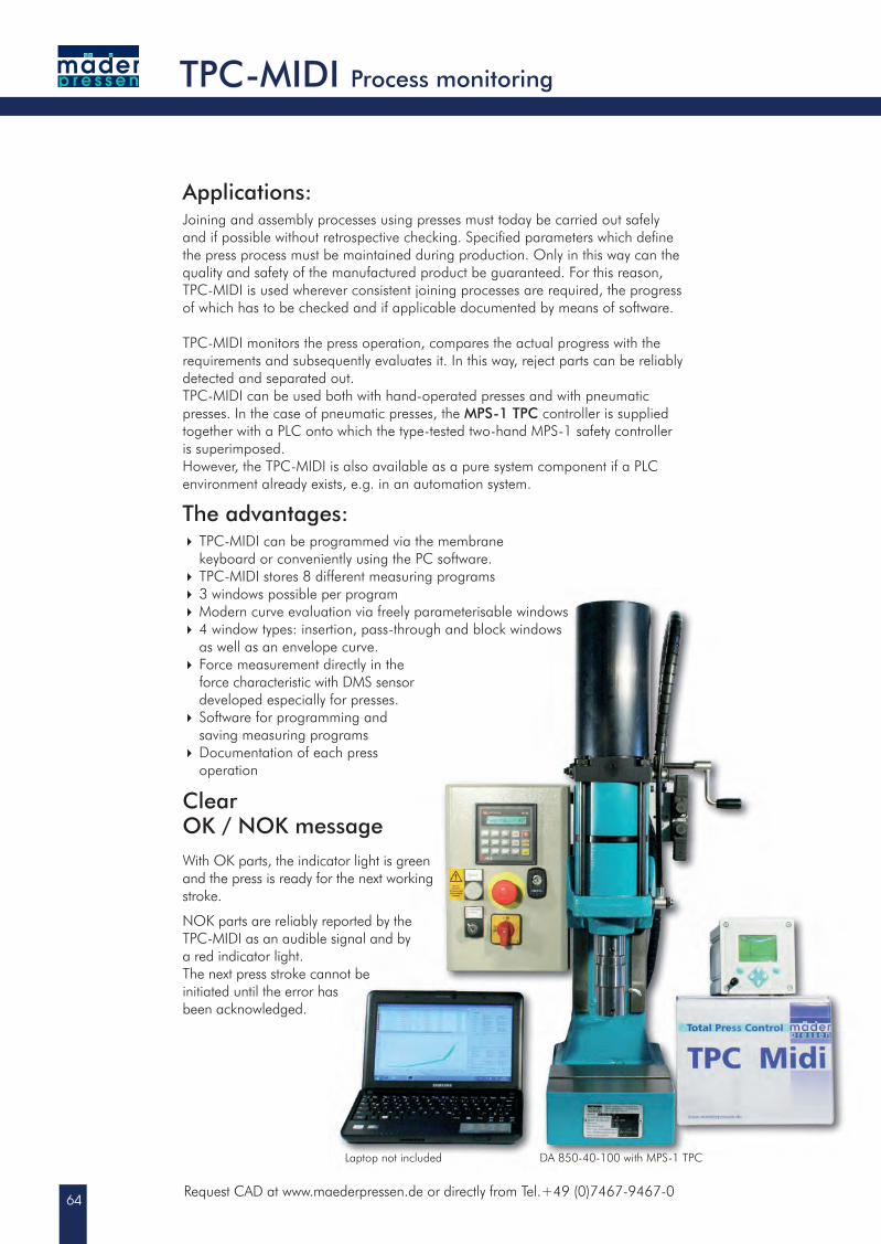
Applications:Joining and assembly processes using presses must today be carried out safely and if possible without retrospective checking. Specifi ed parameters which defi ne the press process must be maintained during production. Only in this way can the quality and safety of the manufactured product be guaranteed. For this reason, TPC-MIDI is used wherever consistent joining processes are required, the progress of which has to be checked and if applicable documented by means of software.
TPC-MIDI monitors the press operation, compares the actual progress with the requirements and subsequently evaluates it. In this way, reject parts can be reliably detected and separated out.TPC-MIDI can be used both with hand-operated presses and with pneumatic presses. In the case of pneumatic presses, the MPS-1 TPC controller is supplied together with a PLC onto which the type-tested two-hand MPS-1 safety controller is superimposed.However, the TPC-MIDI is also available as a pure system component if a PLC environment already exists, e.g. in an automation system.
The advantages: TPC-MIDI can be programmed via the membrane keyboard or conveniently using the PC software. TPC-MIDI stores 8 different measuring programs 3 windows possible per program Modern curve evaluation via freely parameterisable windows 4 window types: insertion, pass-through and block windows as well as an envelope curve. Force measurement directly in the
force characteristic with DMS sensor developed especially for presses. Software for programming and
saving measuring programs Documentation of each press operation
ClearOK / NOK messageWith OK parts, the indicator light is green and the press is ready for the next working stroke.
NOK parts are reliably reported by the TPC-MIDI as an audible signal and by a red indicator light.The next press stroke cannot be initiated until the error has been acknowledged.
TPC-MIDI Process monitoring
Laptop not included DA 850-40-100 with MPS-1 TPC
65
Proc
ess
mon
itorin
g
Process monitoring
TPC-MIDI
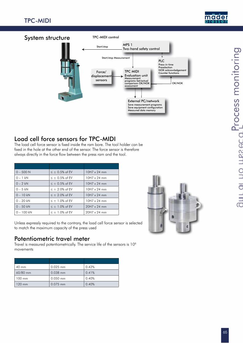
Load cell force sensors for TPC-MIDIThe load cell force sensor is fixed inside the ram bore. The tool holder can be fixed in the hole at the other end of the sensor. The force sensor is therefore always directly in the force flow between the press ram and the tool.
0 – 500 N ≤ ± 0.5% of EV 10H7 x 24 mm
0 – 1 kN ≤ ± 0.5% of EV 10H7 x 24 mm
0 – 2 kN ≤ ± 0.5% of EV 10H7 x 24 mm
0 – 5 kN ≤ ± 2.0% of EV 10H7 x 24 mm
0 – 10 kN ≤ ± 2.0% of EV 10H7 x 24 mm
0 – 20 kN ≤ ± 1.0% of EV 10H7 x 24 mm
0 – 50 kN ≤ ± 1.0% of EV 20H7 x 24 mm
0 – 100 kN ≤ ± 1.0% of EV 20H7 x 24 mm
Unless expressly required to the contrary, the load cell force sensor is selected to match the maximum capacity of the press used
Potentiometric travel meter Travel is measured potentiometrically. The service life of the sensors is 108 movements
40 mm 0.025 mm 0.42%
60/80 mm 0.038 mm 0.41%
100 mm 0.050 mm 0.40%
120 mm 0.075 mm 0.40%
TPC-MIDI control
MPS 1 Two-hand safety control
Force/displacement
sensors
TPC MIDIEvaluation unitMeasurement programs Set/actual comparison OK/NOK assessment
External PC/networkSave measurement programsSave equipment configurationMeasured data memory
PLCPress-in timePreselectionNOK acknowledgement Counter functions
OK/NOK
Start/stop Measurement
Start/stop
System structure
66Request CAD at www.maederpressen.de or directly from Tel.+49 (0)7467-9467-0
TPC-MIDI Process monitoring
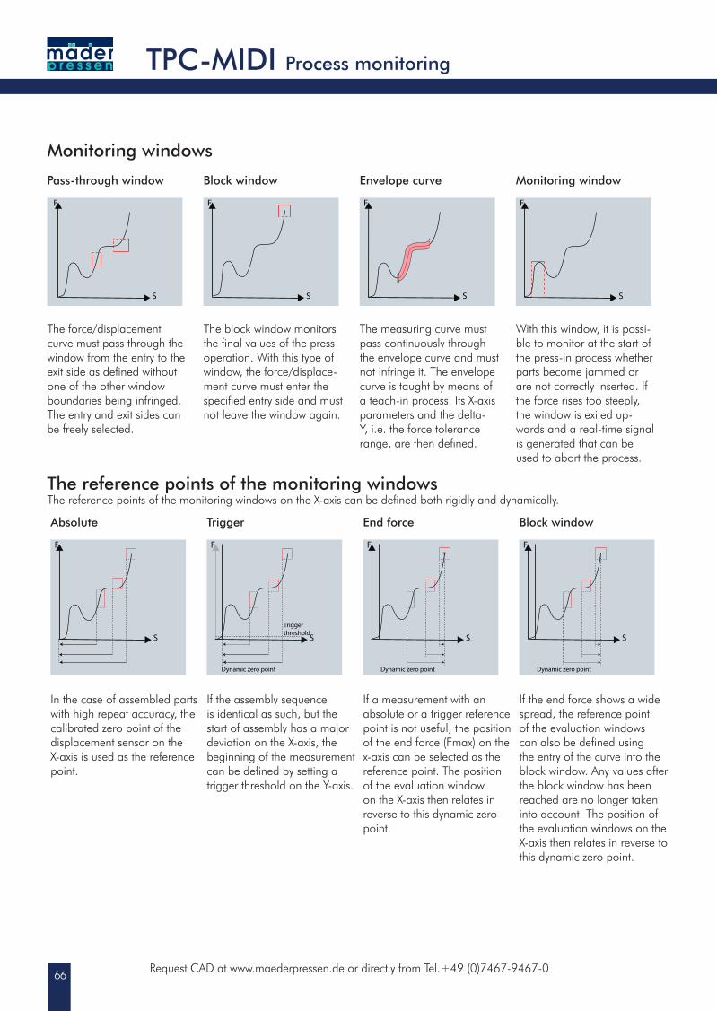
Monitoring windows
Pass-through window
F
S
Block window
F
S
Envelope curve
F
S
Monitoring window
F
S
The force/displacement curve must pass through the window from the entry to the exit side as defined without one of the other window boundaries being infringed. The entry and exit sides can be freely selected.
The block window monitors the final values of the press operation. With this type of window, the force/displace-ment curve must enter the specified entry side and must not leave the window again.
The measuring curve must pass continuously through the envelope curve and must not infringe it. The envelope curve is taught by means of a teach-in process. Its X-axis parameters and the delta-Y, i.e. the force tolerance range, are then defined.
With this window, it is possi-ble to monitor at the start of the press-in process whether parts become jammed or are not correctly inserted. If the force rises too steeply, the window is exited up-wards and a real-time signal is generated that can be used to abort the process.
The reference points of the monitoring windowsThe reference points of the monitoring windows on the X-axis can be defined both rigidly and dynamically.
Absolute
F
S
Trigger
F
S
Trigger threshold
Dynamic zero point
End force
F
S
Dynamic zero point
Block window
F
S
Dynamic zero point
In the case of assembled parts with high repeat accuracy, the calibrated zero point of the displacement sensor on the X-axis is used as the referencepoint.
If the assembly sequence is identical as such, but the start of assembly has a major deviation on the X-axis, the beginning of the measurement can be defined by setting a trigger threshold on the Y-axis.
If a measurement with an absolute or a trigger reference point is not useful, the position of the end force (Fmax) on the x-axis can be selected as thereference point. The positionof the evaluation windowon the X-axis then relates inreverse to this dynamic zeropoint.
If the end force shows a wide spread, the reference point of the evaluation windows can also be defined using the entry of the curve into the block window. Any values after the block window has been reached are no longer taken into account. The position of the evaluation windows on the X-axis then relates in reverse tothis dynamic zero point.
67
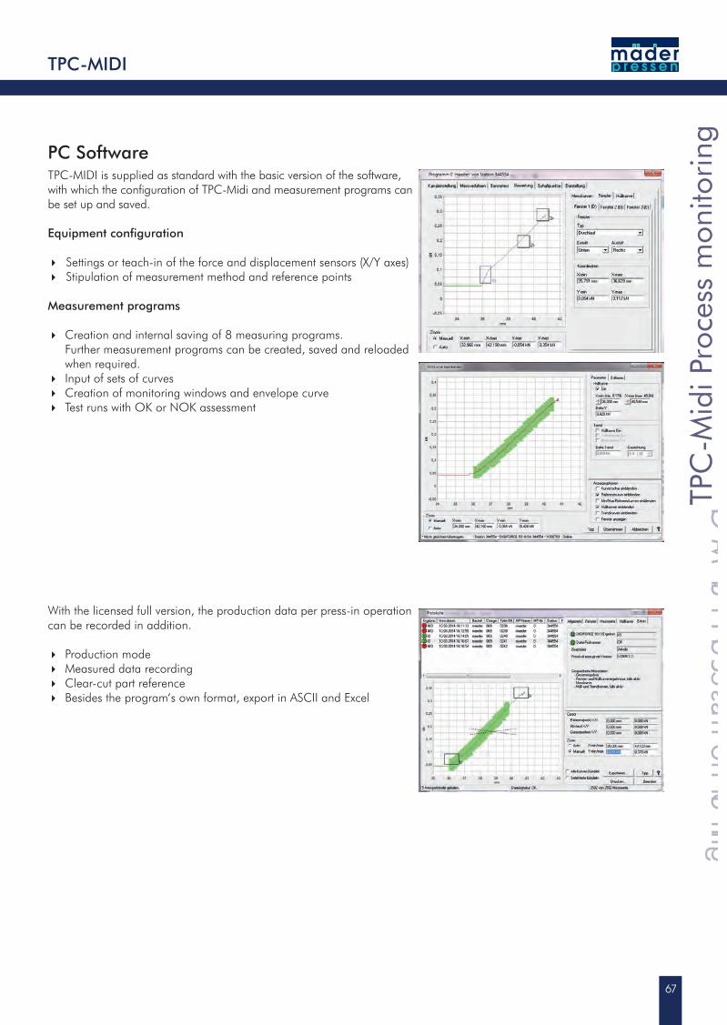
PC SoftwareTPC-MIDI is supplied as standard with the basic version of the software, with which the confi guration of TPC-Midi and measurement programs can be set up and saved.
Equipment confi guration
Settings or teach-in of the force and displacement sensors (X/Y axes) Stipulation of measurement method and reference points
Measurement programs
Creation and internal saving of 8 measuring programs.Further measurement programs can be created, saved and reloaded
when required. Input of sets of curves Creation of monitoring windows and envelope curve Test runs with OK or NOK assessment
With the licensed full version, the production data per press-in operation can be recorded in addition.
Production mode Measured data recording Clear-cut part reference Besides the program‘s own format, export in ASCII and Excel
TPC-MIDI
TPC
-Mid
i Pro
cess
mon
itorin
g
TPC-Midi Process monitoring
TPC
-Mid
i Pro
cess
mon
itorin
g
TPC-Midi Process monitoring
TPC
-Mid
i Pro
cess
mon
itorin
g
Gen
eral
Cat
alog
ue
CONTACT
Sub
ject
to
tec
hn
ical
ch
ang
es f
or
all p
rod
uct
s.G
E081
9EN
GC
ON
TAC
T
CONTACT
Gen
eral
Cat
alog
uemäder pressen GmbH
Robert-Bosch-Str. 13
78579 Neuhausen ob Eck
Germany
Tel.: +49 (0) 74 67 - 94 67 - 0
Fax: +49 (0) 74 67 - 94 67 - 50
www.maederpressen.de
made in Germany by:
Manual presses
Pneumatic presses
Hydropneumatic presses
Related Documents