© ISO 2018 – All rights reserved Document type: International Standard Document subtype: Document stage: (20) Preparatory Document language: E C:\Users\christiangeis\Documents\Normen\12238_ISO_Pneu_Ventschaltzeiten\ISO\2018-09 NP\ISO_12238_(E) 2018-09-25.docx STD Version 2.9d ISO/TC 131/SC 5 N Date: 2018-09-25 ISO/NP 12238.2:2018(E) TC 131/SC 5/WG 3 Secretariat: ANSI Pneumatic fluid power — Directional control valves — Measurement of shifting time Transmissions pneumatiques — Distributeurs de commande directionnels — Mesure du temps de commutation Warning This document is not an ISO International Standard. It is distributed for review and comment. It is subject to change without notice and may not be referred to as an International Standard. Recipients of this draft are invited to submit, with their comments, notification of any relevant patent rights of which they are aware and to provide supporting documentation.

Welcome message from author
This document is posted to help you gain knowledge. Please leave a comment to let me know what you think about it! Share it to your friends and learn new things together.
Transcript

© ISO 2018 – All rights reserved
Document type: International Standard Document subtype: Document stage: (20) Preparatory Document language: E C:\Users\christiangeis\Documents\Normen\12238_ISO_Pneu_Ventschaltzeiten\ISO\2018-09 NP\ISO_12238_(E) 2018-09-25.docx STD Version 2.9d
ISO/TC 131/SC 5 N Date: 2018-09-25
ISO/NP 12238.2:2018(E)
TC 131/SC 5/WG 3
Secretariat: ANSI
Pneumatic fluid power — Directional control valves — Measurement of shifting time
Transmissions pneumatiques — Distributeurs de commande directionnels — Mesure du temps de commutation
Warning
This document is not an ISO International Standard. It is distributed for review and comment. It is subject to change without notice and may not be referred to as an International Standard.
Recipients of this draft are invited to submit, with their comments, notification of any relevant patent rights of which they are aware and to provide supporting documentation.
ISO/NP 12238:2018(E)
ii © ISO 2018 – All rights reserved
Copyright notice
This ISO document is a working draft or committee draft and is copyright-protected by ISO. While the reproduction of working drafts or committee drafts in any form for use by participants in the ISO standards development process is permitted without prior permission from ISO, neither this document nor any extract from it may be reproduced, stored or transmitted in any form for any other purpose without prior written permission from ISO.
Requests for permission to reproduce this document for the purpose of selling it should be addressed as shown below or to ISO's member body in the country of the requester: [Indicate the full address, telephone number, fax number, telex number, and electronic mail address, as appropriate, of the Copyright Manager of the ISO member body responsible for the secretariat of the TC or SC within the framework of which the working document has been prepared.]
Reproduction for sales purposes may be subject to royalty payments or a licensing agreement.
Violators may be prosecuted.
ISO/NP 12238:2018(E)
© ISO 2018 – All rights reserved iii
Contents Page
Foreword ......................................................................................................................................................................... iv
Introduction ................................................................................................................................................................... iv
1 Scope ....................................................................................................................................................................1
2 Normative references ....................................................................................................................................1
3 Terms and definitions ....................................................................................................................................1
4 Symbols and abbreviated terms .................................................................................................................2
5 Test equipment .................................................................................................................................................3 5.1 Basic test setup .................................................................................................................................................3 5.2 Pressure measuring tubes ............................................................................................................................4 5.3 Pressure transducers .....................................................................................................................................4 5.4 Supply reservoir ...............................................................................................................................................5 5.5 Control signal ....................................................................................................................................................5 5.6 Data recording system ...................................................................................................................................5 5.7 Flow control valves .........................................................................................................................................7
6 Test accuracy .....................................................................................................................................................7
7 Test procedure .................................................................................................................................................8
8 Data calculations ........................................................................................................................................... 10
9 Reporting of test data .................................................................................................................................. 11
10 Identification statement (reference to this International Standard) ........................................ 11
(informative) Example of generated test data and values to be reported ........................... 12
Bibliography ................................................................................................................................................................. 13
ISO/NP 12238:2018(E)
iv © ISO 2018 – All rights reserved
Foreword
ISO (the International Organization for Standardization) is a worldwide federation of national standards bodies (ISO member bodies). The work of preparing International Standards is normally carried out through ISO technical committees. Each member body interested in a subject for which a technical committee has been established has the right to be represented on that committee. International organizations, governmental and non-governmental, in liaison with ISO, also take part in the work. ISO collaborates closely with the International Electrotechnical Commission (IEC) on all matters of electrotechnical standardization.
The procedures used to develop this document and those intended for its further maintenance are described in the ISO/IEC Directives, Part 1. In particular the different approval criteria needed for the different types of ISO documents should be noted. This document was drafted in accordance with the editorial rules of the ISO/IEC Directives, Part 2 (see www.iso.org/directives).
Attention is drawn to the possibility that some of the elements of this document may be the subject of patent rights. ISO shall not be held responsible for identifying any or all such patent rights. Details of any patent rights identified during the development of the document will be in the Introduction and/or on the ISO list of patent declarations received (see www.iso.org/patents).
Any trade name used in this document is information given for the convenience of users and does not constitute an endorsement.
For an explanation on the voluntary nature of standards, the meaning of ISO specific terms and expressions related to conformity assessment, as well as information about ISO's adherence to the World Trade Organization (WTO) principles in the Technical Barriers to Trade (TBT) see the following URL: www.iso.org/iso/foreword.html.
This document was prepared by ISO/TC 131, Fluid power systems, Subcommittee SC 5, Control products and components.
This second edition cancels and replaces the first edition (ISO 12238:2001) which has been technically revised.

ISO/NP 12238:2018(E)
© ISO 2018 – All rights reserved v
Introduction
In pneumatic fluid power systems, power is transmitted and controlled through a gas under pressure circulating within a circuit. In some applications, the designer of a fluid power system needs to know the time required to cause the valving elements in a pneumatic directional control valve to move and to generate an output signal.


ISO/NP 12238:2018 (E)
© ISO 2018 – All rights reserved 1
Pneumatic fluid power — Directional control valves — Measurement of shifting time
1 Scope
This International Standard
— is applicable to monostable and bistable pneumatic directional control valves, with 2 or 3 position functions
— specifies test procedures for measuring the shifting times of electrically- or pneumatically-operated directional control valves,
— establishes a definition for shifting time, and
— is intended to improve the application of pneumatic fluid power by providing users and manufacturers of pneumatic valves with a standardized test procedure for measuring the shifting time it defines.
2 Normative references
The following documents, in whole or in part, are normatively referenced in this document and are indispensable for its application. For dated references, only the edition cited applies. For undated references, the latest edition of the referenced document (including any amendments) applies.
ISO 1000, SI units and recommendations for the use of their multiples and of certain other units.
ISO 1219-1, Fluid power systems and components — Graphical symbols and circuit diagrams — Part 1: Graphical symbols for conventional use and data-processing applications.
ISO 5598, Fluid power systems and components — Vocabulary.
ISO 6358-1:2013, Pneumatic fluid power — Determination of flow-rate characteristics of components using compressible fluids — Part 1: General rules and test methods for steady-state flow
3 Terms and definitions
For the purposes of this document, the terms and definitions given in ISO 5598 and the following apply.
3.1 shifting time time lapse measured from a change in the control signal (electrical or pneumatic) until the time at which the pressure in the associated outlet port changes by 10% between specified pressure levels, with only a pressure transducer connected to the outlet

ISO/NP 12238:2018(E)
2 © ISO 2018 – All rights reserved
3.2 shifting on-time shifting time when the control signal is applied
3.3 shifting off-time shifting time when the control signal is removed
4 Symbols and abbreviated terms
4.1 The symbols and units for parameters used in this International Standard shall be as given in Table 1.
Table 1 — Symbol and units
Symbol Parameter Unit (in accordance with ISO 1000)
d Inside diameter of pressure measuring tube mm
p1 Supply reservoir pressure kPa (bar)a
p3 Control pressure kPa (bar)
t0 Base for time measurement ms
tE Exhaust shifting time ms
tF Fill shifting time ms
θ1 Supply reservoir temperature °C a 1 bar = 105 Pa = 100 kPa = 0,1 MPa; 1 Pa = 1 N/m2
4.2 Graphic symbols used in this International Standard conform to the requirements of ISO 1219-1.

ISO/NP 12238:2018(E)
© ISO 2018 – All rights reserved 3
5 Test equipment
5.1 Basic test setup
The basic test equipment shall be as shown in Figures 1 and 2.
When shifting into a non-exhausting valve position the shifting time cannot be measured due to a lack of a pressure drop. For shifting tests For measuring the shifting off-time into non-exhausting valve positions (e.g. 2/2 closed position and 5/3 closed center position) a throttle valve shall be used.
Key 1. Control signal 2. Pressure transducers 3. Output recording device(s) 4. Valve under test 5. Pressure measuring tube in accordance with ISO 6358 6. Shut-off valve (optional) 7. Thermometer 8. Supply reservoir 9. Throttle valve (optional)
Figure 1 — Test equipment for electrically-operated valves

ISO/NP 12238:2018(E)
4 © ISO 2018 – All rights reserved
Key 1. Control signalvalve (to generate control signal) 2. Pressure transducers 3. Output recording device(s) 4. Valve under test 5. Pressure measuring tube in accordance with ISO 6358 6. Shut-off valve (optional) 7. Thermometer 8. Supply reservoir 9. Throttle valve (optional)
Figure 2 — Test equipment for pneumatically-operated valves
For pneumatically operated valves (Figure 2) the C value of the control valve (key 10) shall be greater larger than the C value of the pilot port of the valve under test (key 4). Further the connection between control valve (key 10) and the pressure measuring tube (key 5) at the pilot port of the valve under test should be as short as possible.
5.2 Pressure measuring tubes
5.2.1 A straight pressure measuring tube shall be made to threaded into the valve inlet port, as well as into the valve pilot port when applicable, and shall be made in accordance with 5.4 of ISO 6358 6358-1:2013 (pressure measuring tubes from the earlier edition of ISO 6358:1989 are also permissible).
5.2.2 Select and attach pressure measuring tubes to the test valve whose threads correspond to each port size of the valve flow path, and to the valve pilot port when applicable.
5.3 Pressure transducers
5.3.1 Install a pressure transducer directly into each outlet port to be tested, as well as into the inlet pressure measuring tube.
ISO/NP 12238:2018(E)
© ISO 2018 – All rights reserved 5
5.3.2 When a pneumatically-operated valve is tested, mount the an additional control pressure transducer into the pilot pressure measuring tube.
5.3.3 Use pressure transducers, amplifiers and recording devices that together have a system frequency response of within –3,0 dB at 2000 Hz and a reference time to a known base resolvable to less than 0,1 ms.
5.3.4 Changes in the shifting time caused by limitation of the negative voltage peaks due to the test equipment should not exceed 0,1 ms.
5.4 Supply reservoir
5.4.1 Use a supply reservoir of sufficient capacity so that the pressure drop caused by the piping and measured in the flow pressure measuring tube at the inlet port during the test does not exceed 3 % of the supply pressure. A larger pressure drop is permissible but will increase the shifting time and result in a less favourable rating for the product under test. Connections from the supply reservoir should be several times larger than the pressure measuring tube and as short as possible, to minimize the pressure drop.
5.4.2 Use a supply reservoir that provides for allows measuring of the internal air temperature of the reservoir. Maintain the supply reservoir temperature between 18 °C and 30 °C.
5.4.3 Locate the optional shut-off valve, and the control valve when applicable, as close as possible to the reservoir outlet. Use a valve whose C value flow area is larger than that of the pressure measuring tube, because a smaller valve can restrict the flow and increase the shifting time.
5.5 Control signal
5.5.1 For solenoid pilot-operated valves or pneumatically-operated valves, maintain the external pilot supply pressure at either the test pressure supplied to the valve or the maximum rated permitted pilot supply pressure, whichever is less.
5.5.2 For a.c.AC solenoid-operated valves, generate the control signal with a trigger device set to trigger at the zero-voltage crossover point. Maintain voltage to within ±5 2 % of the rated voltage.
5.5.3 For d.c.DC solenoid-operated valves, maintain steady-state voltage to within ±5 2 % of the rated voltage.
5.5.4 For pneumatically-operated valves, maintain the pilot pressure at the same pressure as in the supply reservoir or at the maximum permitted pilot pressure, whichever is less.
5.5.4 For bistable valves add a pause of non-operation between the control signals to make sureensure, that the pilot controls are completely exhausted, before measuring the shifting -on on-time (pre-exhausted condition).
5.6 Data recording system
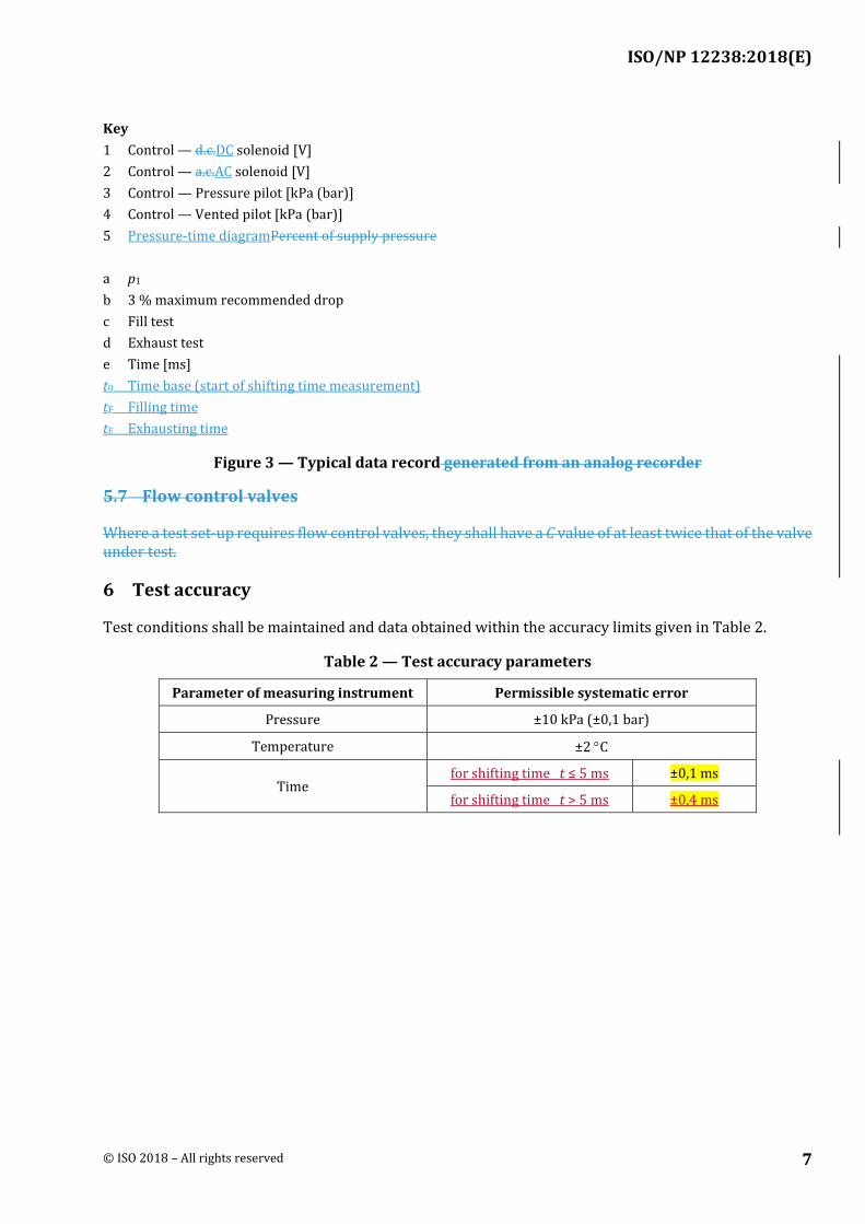
During a test run, record the pressure-time diagram variations with time for all transducers in the system. Figure 3 gives examples of how data from an analogue recorder would appear can look like. Other data recording techniques, including digital methods, which do not produce data in this form, may be used.

ISO/NP 12238:2018(E)
6 © ISO 2018 – All rights reserved
ISO/NP 12238:2018(E)
© ISO 2018 – All rights reserved 7
Key 1 Control — d.c.DC solenoid [V] 2 Control — a.c.AC solenoid [V] 3 Control — Pressure pilot [kPa (bar)] 4 Control — Vented pilot [kPa (bar)] 5 Pressure-time diagramPercent of supply pressure a p1 b 3 % maximum recommended drop c Fill test d Exhaust test e Time [ms] t0 Time base (start of shifting time measurement) tF Filling time tE Exhausting time
Figure 3 — Typical data record generated from an analog recorder
5.7 Flow control valves
Where a test set-up requires flow control valves, they shall have a C value of at least twice that of the valve under test.
6 Test accuracy
Test conditions shall be maintained and data obtained within the accuracy limits given in Table 2.
Table 2 — Test accuracy parameters
Parameter of measuring instrument Permissible systematic error
Pressure ±10 kPa (±0,1 bar)
Temperature ±2 °C
Time for shifting time t ≤ 5 ms ±0,1 ms
for shifting time t > 5 ms ±0,4 ms
ISO/NP 12238:2018(E)
8 © ISO 2018 – All rights reserved
7 Test procedure
7.1 Overview of test procedures
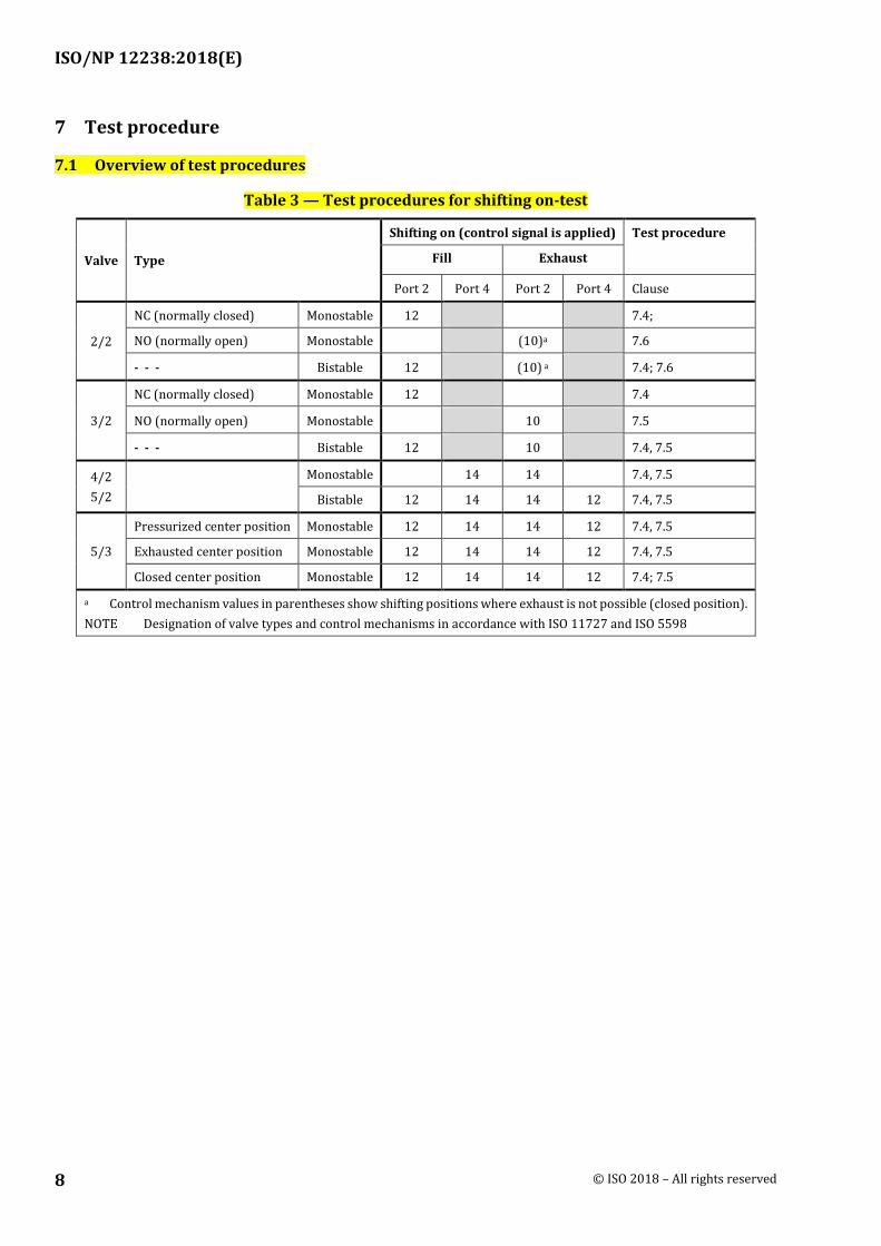
Table 3 — Test procedures for shifting on-test
Valve Type
Shifting on (control signal is applied) Test procedure
Fill Exhaust
Port 2 Port 4 Port 2 Port 4 Clause
2/2
NC (normally closed) Monostable 12 7.4;
NO (normally open) Monostable (10)a 7.6
- - - Bistable 12 (10) a 7.4; 7.6
3/2
NC (normally closed) Monostable 12 7.4
NO (normally open) Monostable 10 7.5
- - - Bistable 12 10 7.4, 7.5
4/2 5/2
Monostable 14 14 7.4, 7.5
Bistable 12 14 14 12 7.4, 7.5
5/3
Pressurized center position Monostable 12 14 14 12 7.4, 7.5
Exhausted center position Monostable 12 14 14 12 7.4, 7.5
Closed center position Monostable 12 14 14 12 7.4; 7.5
a Control mechanism values in parentheses show shifting positions where exhaust is not possible (closed position). NOTE Designation of valve types and control mechanisms in accordance with ISO 11727 and ISO 5598

ISO/NP 12238:2018(E)
© ISO 2018 – All rights reserved 9
Table 4 — Test procedures for shifting off-test
Valve Type
Shifting off (control signal is removed) Test procedure
Fill Exhaust
Port 2 Port 4 Port 2 Port 4 Clause
2/2
NC (normally closed) Monostable (12) a 7.6
NO (normally open) Monostable 10 7.4
- - - Bistable ---b
3/2
NC (normally closed) Monostable 12 7.5
NO (normally open) Monostable 10 7.4
- - - Bistable ---b
4/2 5/2
Monostable 14 14 7.4, 7.5
Bistable ---b
5/3
Pressurized center position Monostable 14 12 7.4
Exhausted center position Monostable 12 14 7.5
Closed center position Monostable (12) a (14) a 7.6
a Control mechanism values in parentheses show shifting positions where exhaust is not possible (closed position). b For bistable valves in general the removal of the control signal does not lead to a change of the valve position. Therefore a determination of a shifting off-time is not possible for these kind of valves. NOTE Designation of valve types and control mechanisms in accordance with ISO 11727 and ISO 5598
7.2 Set up the test circuit as shown in Figure 1 or, when appropriate, Figure 2, with components as specified in clause 5.
7.3 The fill and exhaust test time for each outlet port shall be measured based on the operation capabilities of the valve, either shifting on-time or shifting off-time. The following data shall be recorded:
— fill time from inlet to each outlet port and
— exhaust time from each outlet to exhaust port.
Additional data on other possible flow paths through the valve (for example, two inlets for dual pressure valves) may also be recorded. Test to measure exhaust and fill tests may be combined to run in sequence.
7.4 For filling positions Tthe fill test time shall be determined as follows:
7.4.1 Maintain supply reservoir pressure at a gauge pressure of 630 kPa (6,3 bar) or at the maximum rated working pressure at the inlet pressure transducer, whichever is less.
7.4.2 Vent the outlet port under test to atmosphere.
7.4.3 Maintain the supply reservoir temperature between 18 °C and 30 °C.
7.4.4 Perform several preliminary valve shifts by energizing or de-energizing the solenoid on electrically-operated valves, or by operating the control valve to pressurize or depressurize the pilot control mechanism of a pneumatically-operated valve.

ISO/NP 12238:2018(E)
10 © ISO 2018 – All rights reserved
7.4.5 Perform three test runs for each flow path, venting the outlet port each time and waiting at least 1 min before performing the next test run, to ensure temperature stabilization.
7.5 For exhausting positions Tthe exhaust test time shall be determined as follows:
7.5.1 Charge the outlet port under test to a gauge pressure of 630 kPa (6,3 bar) or to the maximum rated working pressure at the outlet pressure transducer, whichever is less.
7.5.2 Maintain the supply reservoir temperature between 18°C and 30 °C.
7.5.3 Perform several preliminary valve shifts by energizing or de-energizing the solenoid on electrically-operated valves, or by operating the control valve to pressurize or depressurize the pilot control mechanism of a pneumatically-operated valve.
7.5.4 Perform three test runs for each flow path, pressurizing the outlet port each time and waiting at least 1 min. before performing the next test run, to ensure temperature stabilization.
7.6 For non-exhausting shifting positions (e.g. 2/2 closed position and 5/3 closed center position) the shifting characteristics shall be determined as follows:
7.6.1 Maintain supply reservoir pressure at a pressure of 630 kPa (6,3 bar) or at the maximum rated pressure at the inlet pressure transducer, whichever is less. Shift the valve to the pressurized position. Open the throttle valve until a small leakage is present while the outlet port is pressurized (max. 0,1 bar pressure drop at the outlet pressure transducer compared to the inlet pressure transducer). A pressure decrease shall be detectable, when the valve is shifted to the non-exhausting position.
NOTE Pressure drop of 0,1 bar ensures that the measurement is conducted close to the reference test pressure of 6,3 bar so that the shifting characteristic is not influenced.
7.6.2 With the throttle valve open, perform several preliminary shifts by energizing and de-energizing the solenoid on electrically operated valves or by operating a control valve to pressurize and depressurize the pilot control mechanism on pneumatically operated valves.
7.6.3 Shift the valve to the pressurized position. Then shift it to the non-exhausting position and measure the shifting time at the start (0 % pressure decrease) of the pressure decrease as described in clause 5.6. Fix the pressure drop as close to 0% as possible. The inlet pressure shall be constant and the noise of the pressure signal shall be taken in account.
NOTE For the measurements according to this section the rate of the pressure drop is not relevant. Only the time at the beginning is recorded (0 %-measurement).
8 Data calculations
8.1 For electrically-operated valves, establish the time base (t0) as the point at which a definite change in the voltage is noted (see Figure 3).
8.2 For pneumatically-operated valves, establish the time base (t0) as the point at which a 10 % change in pilot pressure is noted (see Figure 3).
8.3 Measure the time to fill from t0 to the point at which the pressure reaches 10 % of its supply reservoir pressure value for each test run of an outlet port. Determine the average of the data from the several test runs defined in clause 7.4 for each outlet port; this is the fill shifting time for each outlet port (see Table A.1 for an example of test data).

ISO/NP 12238:2018(E)
© ISO 2018 – All rights reserved 11
8.4 Measure the time to exhaust from t0 to the point at which the pressure reaches 90 % of its supply reservoir pressure value for each test run of an outlet port. Determine the average of the data from the several test runs defined in clause 7.5 for each outlet port; this is the exhaust shifting time for each outlet port (see Table A.1 for an example of test data).
8.5 Measure the time to exhaust by throttle for non-exhausting shifting positions from t0 to the point at the start (0 % pressure decrease) of the pressure decrease for each test run of an outlet port. Determine the average of the data from the test runs defined in clause 7.6 for each outlet port; this is the shifting time for each outlet port.
9 Reporting of test data
9.1 Report the average shifting time for each flow path in the valve; see the column titled “Each flow path” in Table A.1 for an example of this type of reporting.
9.2 As an alternative to clause 9.1, report the average of shifting time for all flow paths in a valve, with a bilateral tolerance that includes the extremes of the data recorded; see the column titled “Valve as a whole” in Table A.1 for an example of this type of reporting.
10 Identification statement (reference to this International Standard)
It is strongly recommended that manufacturers use the following statement in test reports, catalogues and sales literature when electing to comply with this International Standard:
“Shifting time of pneumatic directional control valves or moving part logic devices was measured in accordance with ISO 12238:20XX, Pneumatic fluid power — Directional control valves — Measurement of shifting time.”
ISO/NP 12238:2018(E)
12 © ISO 2018 – All rights reserved
(informative)
Example of generated test data and values to be reported
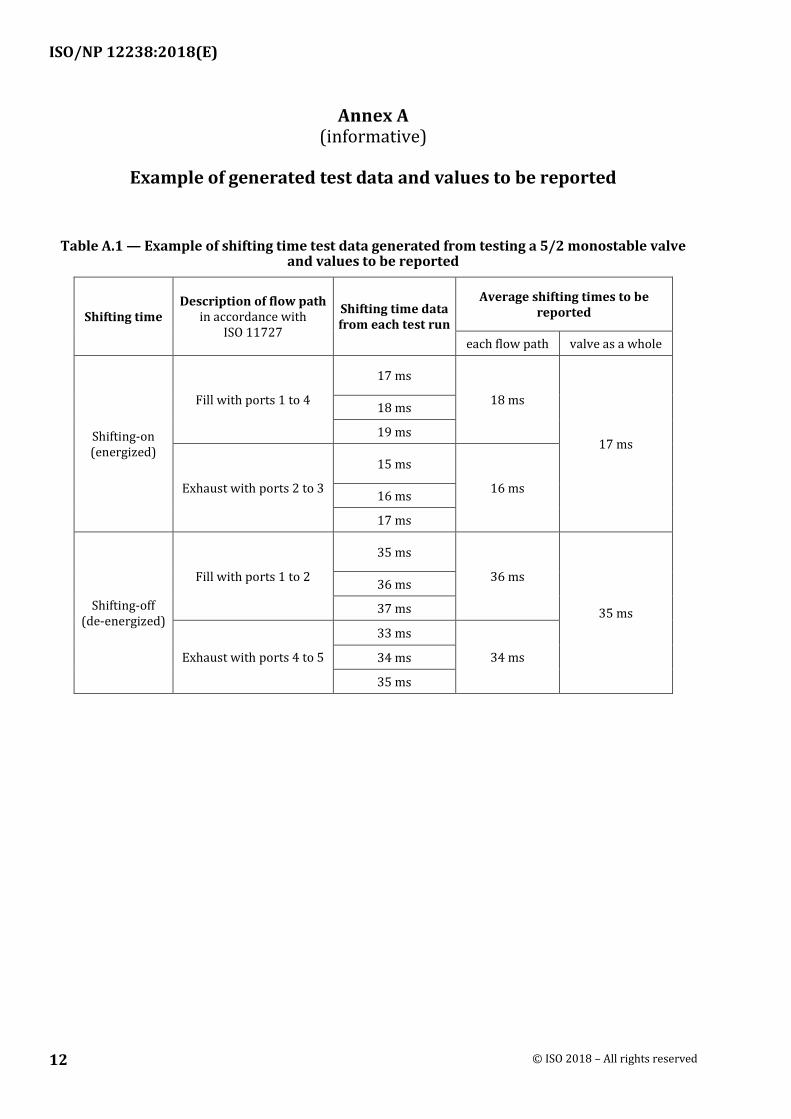
Table A.1 — Example of shifting time test data generated from testing a 5/2 monostable valve and values to be reported
Shifting time Description of flow path
in accordance with ISO 11727
Shifting time data from each test run
Average shifting times to be reported
each flow path valve as a whole
Shifting-on (energized)
Fill with ports 1 to 4
17 ms
18 ms
17 ms
18 ms
19 ms
Exhaust with ports 2 to 3
15 ms
16 ms 16 ms
17 ms
Shifting-off (de-energized)
Fill with ports 1 to 2
35 ms
36 ms
35 ms
36 ms
37 ms
Exhaust with ports 4 to 5
33 ms
34 ms 34 ms
35 ms

ISO/NP 12238:2018(E)
© ISO 2018 – All rights reserved 13
Bibliography
ISO 11727:1999, Pneumatic fluid power — Identification of ports and control mechanisms of control valves and other components.
Related Documents