PNEUMATIC CONTROL FUNDAMENTALS 57 ENGINEERING MANUAL OF AUTOMATIC CONTROL Contents Introduction ............................................................................................................ 59 Definitions ............................................................................................................ 59 Abbreviations ............................................................................................................ 60 Symbols ............................................................................................................ 61 Basic Pneumatic Control System ............................................................................................................ 61 General ................................................................................................ 61 Air Supply and Operation .................................................................... 61 Restrictor ............................................................................................. 62 Nozzle-Flapper Assembly .................................................................... 62 Pilot Bleed System .............................................................................. 62 Signal Amplifier .................................................................................... 63 Feed and Bleed System ...................................................................... 63 Sensing Elements ............................................................................... 63 Bimetal ............................................................................................ 63 Rod and Tube ................................................................................. 64 Remote Bulb ................................................................................... 64 Averaging Element .......................................................................... 64 Throttling Range Adjustment ............................................................... 64 Relays and Switches ........................................................................... 65 Air Supply Equipment ............................................................................................................ 65 General ................................................................................................ 65 Air Compressor ................................................................................... 65 Air Drying Techniques ......................................................................... 66 General ........................................................................................... 66 Dry Air Requirement ........................................................................ 66 Condensing Drying ......................................................................... 67 High-Pressure Drying ................................................................. 67 Refrigerant Drying ....................................................................... 67 Desiccant Drying ............................................................................. 67 Pressure Reducing Valve Station ........................................................ 68 Air Filter ........................................................................................... 68 Pressure Reducing Valves .............................................................. 69 Single-Pressure Reducing Valve ................................................ 69 Two-Pressure Reducing Valve .................................................... 69 Thermostats ............................................................................................................ 69 Pneumatic Control Fundamentals

Welcome message from author
This document is posted to help you gain knowledge. Please leave a comment to let me know what you think about it! Share it to your friends and learn new things together.
Transcript

PNEUMATIC CONTROL FUNDAMENTALS
57 ENGINEERING MANUAL OF AUTOMATIC CONTROL
Contents
Introduction ............................................................................................................ 59
Definitions ............................................................................................................ 59
Abbreviations ............................................................................................................ 60
Symbols ............................................................................................................ 61
Basic Pneumatic Control System ............................................................................................................ 61General ................................................................................................ 61Air Supply and Operation .................................................................... 61Restrictor ............................................................................................. 62Nozzle-Flapper Assembly .................................................................... 62Pilot Bleed System .............................................................................. 62Signal Amplifier .................................................................................... 63Feed and Bleed System ...................................................................... 63Sensing Elements ............................................................................... 63
Bimetal ............................................................................................ 63Rod and Tube ................................................................................. 64Remote Bulb ................................................................................... 64Averaging Element .......................................................................... 64
Throttling Range Adjustment ............................................................... 64Relays and Switches ........................................................................... 65
Air Supply Equipment ............................................................................................................ 65General ................................................................................................ 65Air Compressor ................................................................................... 65Air Drying Techniques ......................................................................... 66
General ........................................................................................... 66Dry Air Requirement ........................................................................ 66Condensing Drying ......................................................................... 67
High-Pressure Drying ................................................................. 67Refrigerant Drying....................................................................... 67
Desiccant Drying ............................................................................. 67Pressure Reducing Valve Station ........................................................ 68
Air Filter ........................................................................................... 68Pressure Reducing Valves .............................................................. 69
Single-Pressure Reducing Valve ................................................ 69Two-Pressure Reducing Valve .................................................... 69
Thermostats ............................................................................................................ 69
Pneumatic ControlFundamentals
PNEUMATIC CONTROL FUNDAMENTALS
ENGINEERING MANUAL OF AUTOMATIC CONTROL 58
Controllers ............................................................................................................ 70General ................................................................................................ 70Temperature Controllers ...................................................................... 71Humidity Controllers ............................................................................ 71Pressure Controllers ............................................................................ 71Sensor-Controller Systems ................................................................. 72Pneumatic Controllers ......................................................................... 72
Proportional-Integral (PI) Controllers .............................................. 72Controller Adjustments .................................................................... 72
Pneumatic Sensors ............................................................................. 73Velocity Sensor-Controller ................................................................... 73
Actuators and Final Control Elements ............................................................................................................ 74Actuators ............................................................................................. 74
General ........................................................................................... 74Spring Ranges ................................................................................ 74
Control Valves ..................................................................................... 75Dampers .............................................................................................. 76
Relays and Switches ............................................................................................................ 77Switching Relay ................................................................................... 77Snap Acting Relay ............................................................................... 78Lockout Relay ...................................................................................... 78High-Pressure Selector Relay ............................................................. 79Low-Pressure Selector Relay .............................................................. 79Load Analyzer Relay ........................................................................... 79Capacity Relay .................................................................................... 80Reversing Relay .................................................................................. 80Averaging Relay .................................................................................. 80Positive-Positioning Relay ................................................................... 80Ratio Relay .......................................................................................... 81Pneumatic Potentiometer .................................................................... 81Hesitation Relay .................................................................................. 82Electrical Interlocking Relays .............................................................. 82
Electric-Pneumatic Relay ................................................................ 82Pneumatic-Electric Relay ................................................................ 82
Electronic-Pneumatic Transducer ....................................................... 83Pneumatic Switch ................................................................................ 83Manual Positioning Switch .................................................................. 84
Pneumatic Control Combinations ............................................................................................................ 84General ................................................................................................ 84Sequence Control ................................................................................ 85Limit Control ........................................................................................ 85Manual Switch Control ........................................................................ 86Changeover Control for Two-Pressure Supply System ....................... 87Compensated Control System ............................................................ 87Electric-Pneumatic Relay Control ........................................................ 87Pneumatic-Electric Relay Control ........................................................ 88Pneumatic Recycling Control .............................................................. 88
Pneumatic Centralization ............................................................................................................ 89
Pneumatic Control System Example ............................................................................................................ 90Start-Stop Control Sequence .............................................................. 90Supply Fan Control Sequence ............................................................ 92Return Fan Control Sequence............................................................. 92Warm-up/Heating Coil Control Sequence ........................................... 92Mixing Damper Control Sequence ...................................................... 93Discharge Air Temperature Control Sequence .................................... 94Off/Failure Mode Control Sequence .................................................... 94
PNEUMATIC CONTROL FUNDAMENTALS
59 ENGINEERING MANUAL OF AUTOMATIC CONTROL
INTRODUCTION
This section provides basic information on pneumatic controlsystems and components commonly used to control equipmentin commercial heating and air conditioning applications. Theinformation in this section is of a general nature in order toexplain the fundamentals of pneumatic control. Some termsand references may vary between manufacturers (e.g., switchport numbers).
Pneumatic control systems use compressed air to operateactuators, sensors, relays, and other control equipment.Pneumatic controls differ from other control systems in severalways with some distinct advantages:
— Pneumatic equipment is inherently proportional but canprovide two-position control when required.
— Many control sequences and combinations are possible
with relatively simple equipment.— Pneumatic equipment is suitable where explosion
hazards exist.— The installed cost of pneumatic controls and materials
may be lower, especially where codes require that low-voltage electrical wiring for similar electric controls berun in conduit.
— Quality, properly installed pneumatic equipment isreliable. However, if a pneumatic control system requirestroubleshooting or service, most building-maintenancepeople have the necessary mechanical knowledge.
DEFINITIONS
Actuator: A mechanical device that operates a final controlelement (e.g., valve, damper).
Authority (Reset Authority or Compensation Authority):A setting that indicates the relative effect acompensation sensor input has on the main setpoint(expressed in percent).
Branch line: The air line from a controller to the controlleddevice.
Branchline pressure (BLP): A varying air pressure signalfrom a controller to an actuator carried by the branchline. Can go from atmospheric to full main linepressure.
Compensation changeover: The point at which thecompensation effect is reversed in action and changesfrom summer to winter or vice versa. The percent ofcompensation effect (authority) may also be changedat the same time.
Compensation control: A process of automatically adjustingthe control point of a given controller to compensatefor changes in a second measured variable such asoutdoor air temperature. For example, the hot deckcontrol point is reset upward as the outdoor airtemperature decreases. Also know as “reset control”.
Compensation sensor: The system element which senses avariable other than the controlled variable and resetsthe main sensor control point. The amount of thiseffect is established by the authority setting.
Control point: The actual value of the controlled variable(setpoint plus or minus offset).
Controlled variable: The quantity or condition that is measuredand controlled (e.g., temperature, relative humidity,pressure).
Controller: A device that senses the controlled variable orreceives an input signal from a remote sensingelement, compares the signal with the setpoint, andoutputs a control signal (branchline pressure) to anactuator.
Differential: A term that applies to two-position devices. Therange through which the controlled variable must passin order to move the final control element from one tothe other of its two possible positions. The differencebetween cut-in and cut-out temperatures, pressures, etc.
Direct acting (DA): A direct-acting thermostat or controllerincreases the branchline pressure on an increase inthe measured variable and decreases the branchlinepressure on a decrease in the variable. A direct-actingactuator extends the shaft on an increase in branchlinepressure and retracts the shaft on a decrease inpressure.
Discharge air: Conditioned air that has passed through a coil.Also, air discharged from a supply duct outlet into aspace. See Supply air.
Final control element: A device such as a valve or damperthat acts to change the value of the manipulatedvariable. Positioned by an actuator.
PNEUMATIC CONTROL FUNDAMENTALS
ENGINEERING MANUAL OF AUTOMATIC CONTROL 60
Main line: The air line from the air supply system to controllersand other devices. Usually plastic or copper tubing.
Manipulated variable: Media or energy controlled to achievea desired controlled variable condition.
Measuring element: Same as sensing element.
Mixed air: Typically a mixture of outdoor air and return airfrom the space.
Modulating: Varying or adjusting by small increments. Alsocalled “proportional”.
Offset: A sustained deviation between the actual systemcontrol point and its controller setpoint under stableoperating conditions. Usually applies to proportional(modulating) control.
Proportional band: As applied to pneumatic control systems,the change in the controlled variable required tochange the controller output pressure from 3 to 13psi. Usually expressed as a percentage of sensor span.
Reset control: See compensation control.
Restrictor: A device in an air line that limits the flow of air.
Return air: Air entering an air handling system from theoccupied space.
Reverse acting (RA): A reverse-acting thermostat or controllerdecreases the branchline pressure on an increase inthe measured variable and increases the branchlinepressure on a decrease in the variable. A reverse-actingvalve actuator retracts the shaft on an increase inbranchline pressure and extends the shaft on adecrease in pressure.
Sensing element: A device that detects and measures thecontrolled variable (e.g., temperature, humidity).
Sensor: A device placed in a medium to be measured orcontrolled that has a change in output signal relatedto a change in the sensed medium.
Sensor Span: The variation in the sensed media that causesthe sensor output to vary between 3 and 15 psi.
Setpoint: The value on the controller scale at which thecontroller is set (e.g., the desired room temperatureset on a thermostat). The desired control point.
Supply air: Air leaving an air handling system.
Thermostat: A device that responds to changes in temperatureand outputs a control signal (branchline pressure).Usually mounted on a wall in the controlled space.
Throttling range: Related to proportional band, and expressedin values of the controlled variable (e.g., degrees,percent relative humidity, pounds per square inch)rather than in percent.
ABBREVIATIONS
The following port abbreviations are used in drawings ofrelays and controllers:
B — BranchC — CommonE — Exhaust
M — MainO — Normally connected*X — Normally disconnected*P — Pilot (P
1 and P
2 for dual-pilot relays)
S — Sensor (S1 and S
2 for dual-input controllers)
N.C. — Normally closedN.O. — Normally open
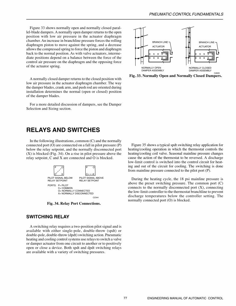
* The normally connected and common ports are connectedon a fall in pilot pressure below the relay setpoint, and thenormally disconnected port is blocked. On a rise in pilotpressure above the relay setpoint, the normally disconnectedand common ports are connected and the normallyconnected port is blocked. Refer to Figure 37 in RELAYSAND SWITCHES.

PNEUMATIC CONTROL FUNDAMENTALS
61 ENGINEERING MANUAL OF AUTOMATIC CONTROL
SYMBOLS
MM OR
OR
MAIN AIR SUPPLY
RESTRICTOR
NOZZLE
FIXED POINT
FULCRUM
PIVOT POINT
C1082
BASIC PNEUMATIC CONTROL SYSTEM
GENERAL
A pneumatic control system is made up of the followingelements:
— Compressed air supply system— Main line distribution system— Branch lines— Sensors— Controllers— Actuators— Final control elements (e.g., valves, dampers)
A basic pneumatic control system consists of an air supply,a controller such as a thermostat, and an actuator positioninga valve or damper (Fig. 1).
In a typical control system, the final control element (a valveor a damper) is selected first because it must produce the desiredcontrol results. For example, a system designed to control theflow of water through a coil requires a control valve. The typeof valve, however, depends on whether the water is intendedfor heating or cooling, the water pressure, and the control andflow characteristics required. An actuator is then selected tooperate the final control element. A controller and relayscomplete the system. When all control systems for a buildingare designed, the air supply system can be sized and designed.
AIR SUPPLY AND OPERATION
The main line air supply is provided by an electrically drivencompressor pumping air into a storage tank at high pressure(Fig. 2). A pressure switch turns the compressor on and off tomaintain the storage tank pressure between fixed limits. Thetank stores the air until it is needed by control equipment. Theair dryer removes moisture from the air, and the filter removesoil and other impurities. The pressure reducing valve (PRV)typically reduces the pressure to 18 to 22 psi. For two-pressure(day/night) systems and for systems designed to change fromdirect to reverse acting (heating/cooling), the PRV switchesbetween two pressures, such as 13 and 18 psi. The maximumsafe air pressure for most pneumatic controls is 25 psi.
C2353
COMPRESSEDAIR SUPPLYSYSTEM
MAIN BRANCH
ACTUATOR
VALVE
THERMOSTAT
TO OTHER CONTROLLERS
M B
Fig. 1. Basic Pneumatic Control System.
The controller receives air from the main line and regulatesits output pressure (branchline pressure) as a function of thetemperature, pressure, humidity, or other variable. Thebranchline pressure from the controller can vary from zero tofull mainline pressure. The regulated branchline pressureenergizes the actuator, which then assumes a positionproportional to the branchline pressure applied. The actuatorusually goes through its full stroke as the branchline pressurechanges from 3 psi to 13 psi. Other pressure ranges areavailable.
AIRSUPPLY
INAIR COMPRESSOR
STORAGETANK
AIR DRYER
FILTER
PRESSUREGAGES
PRESSUREREDUCINGVALVE
MAIN AIR TO PNEUMATICCONTROLSYSTEM
C2616-1
Fig. 2. Compressed Air Supply System.

PNEUMATIC CONTROL FUNDAMENTALS
ENGINEERING MANUAL OF AUTOMATIC CONTROL 62
From the PRV, the air flows through the main line to thecontroller (in Figure 1, a thermostat) and to other controllersor relays in other parts of the system. The controller positionsthe actuator. The controller receives air from the main line at aconstant pressure and modulates that pressure to providebranchline air at a pressure that varies according to changes inthe controlled variable, as measured by the sensing element.The controller signal (branchline pressure) is transmitted viathe branch line to the controlled device (in Figure 1, a valveactuator). The actuator drives the final control element (valve)to a position proportional to the pressure supplied by thecontroller.
When the proportional controller changes the air pressureto the actuator, the actuator moves in a direction and distanceproportional to the direction and magnitude of the change atthe sensing element.
RESTRICTOR
The restrictor is a basic component of a pneumatic controlsystem and is used in all controllers. A restrictor is usually adisc with a small hole inserted into an air line to restrict theamount of airflow. The size of the restrictor varies with theapplication, but can have a hole as small as 0.003 inches.
NOZZLE-FLAPPER ASSEMBLY
The nozzle-flapper assembly (Fig. 3) is the basic mechanismfor controlling air pressure to the branch line. Air supplied tothe nozzle escapes between the nozzle opening and the flapper.At a given air supply pressure, the amount of air escaping isdetermined by how tightly the flapper is held against the nozzleby a sensing element, such as a bimetal. Thus, controlling thetension on the spring also controls the amount of air escaping.Very little air can escape when the flapper is held tightly againstthe nozzle.
To create a branchline pressure, a restrictor (Fig. 3) isrequired. The restrictor and nozzle are sized so that the nozzlecan exhaust more air than can be supplied through the restrictorwhen the flapper is off the nozzle. In that situation, thebranchline pressure is near zero. As the spring tension increasesto hold the flapper tighter against the nozzle, reducing the airescaping, the branchline pressure increases proportionally.When the spring tension prevents all airflow from the nozzle,the branchline pressure becomes the same as the mainlinepressure (assuming no air is flowing in the branch line). Thistype of control is called a “bleed” control because air “bleeds”continuously from the nozzle.
With this basic mechanism, all that is necessary to create acontroller is to add a sensing element to move the flapper asthe measured variable (e.g., temperature, humidity, pressure)changes. Sensing elements are discussed later.
PILOT BLEED SYSTEM
The pilot bleed system is a means of increasing air capacityas well as reducing system air consumption. The restrictor andnozzle are smaller in a pilot bleed system than in a nozzle-flapper system because in a pilot bleed system they supply aironly to a capacity amplifier that produces the branchlinepressure (Fig. 4). The capacity amplifier is a pilot bleedcomponent that maintains the branchline pressure in proportionto the pilot pressure but provides greater airflow capacity.
M
SENSORFORCE
FLAPPER
SPRING
BRANCHRESTRICTOR
AIR SUPPLY
NOZZLE
C1084
Fig. 3. Nozzle-Flapper Assembly with Restrictor.
M
FLAPPER
NOZZLE
BLEEDVALVE
SPRING
VENT
C1085
BRANCH
BRANCHCHAMBER
FEED VALVEDISC
CAPACITYAMPLIFIER
PILOTCHAMBER
Fig. 4. Pilot Bleed System with Amplifier Relay.
The pilot pressure from the nozzle enters the pilot chamberof the capacity amplifier. In the state shown in Figure 4, no airenters or leaves the branch chamber. If the pilot pressure fromthe nozzle is greater than the spring force, the pilot chamberdiaphragm is forced down, which opens the feed valve andallows main air into the branch chamber. When the pilotpressure decreases, the pilot chamber diaphragm rises, closing
PNEUMATIC CONTROL FUNDAMENTALS
63 ENGINEERING MANUAL OF AUTOMATIC CONTROL
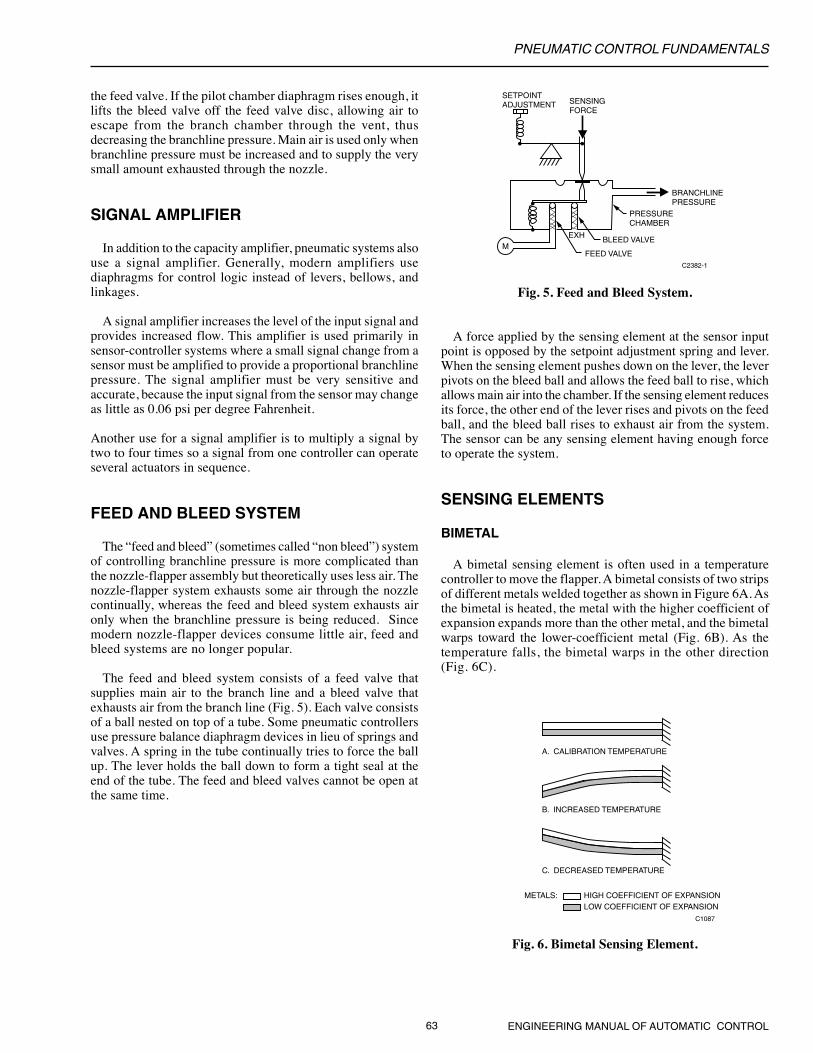
the feed valve. If the pilot chamber diaphragm rises enough, itlifts the bleed valve off the feed valve disc, allowing air toescape from the branch chamber through the vent, thusdecreasing the branchline pressure. Main air is used only whenbranchline pressure must be increased and to supply the verysmall amount exhausted through the nozzle.
SIGNAL AMPLIFIER
In addition to the capacity amplifier, pneumatic systems alsouse a signal amplifier. Generally, modern amplifiers usediaphragms for control logic instead of levers, bellows, andlinkages.
A signal amplifier increases the level of the input signal andprovides increased flow. This amplifier is used primarily insensor-controller systems where a small signal change from asensor must be amplified to provide a proportional branchlinepressure. The signal amplifier must be very sensitive andaccurate, because the input signal from the sensor may changeas little as 0.06 psi per degree Fahrenheit.
Another use for a signal amplifier is to multiply a signal bytwo to four times so a signal from one controller can operateseveral actuators in sequence.
FEED AND BLEED SYSTEM
The “feed and bleed” (sometimes called “non bleed”) systemof controlling branchline pressure is more complicated thanthe nozzle-flapper assembly but theoretically uses less air. Thenozzle-flapper system exhausts some air through the nozzlecontinually, whereas the feed and bleed system exhausts aironly when the branchline pressure is being reduced. Sincemodern nozzle-flapper devices consume little air, feed andbleed systems are no longer popular.
The feed and bleed system consists of a feed valve thatsupplies main air to the branch line and a bleed valve thatexhausts air from the branch line (Fig. 5). Each valve consistsof a ball nested on top of a tube. Some pneumatic controllersuse pressure balance diaphragm devices in lieu of springs andvalves. A spring in the tube continually tries to force the ballup. The lever holds the ball down to form a tight seal at theend of the tube. The feed and bleed valves cannot be open atthe same time.
Fig. 5. Feed and Bleed System.
A force applied by the sensing element at the sensor inputpoint is opposed by the setpoint adjustment spring and lever.When the sensing element pushes down on the lever, the leverpivots on the bleed ball and allows the feed ball to rise, whichallows main air into the chamber. If the sensing element reducesits force, the other end of the lever rises and pivots on the feedball, and the bleed ball rises to exhaust air from the system.The sensor can be any sensing element having enough forceto operate the system.
SENSING ELEMENTS
BIMETAL
A bimetal sensing element is often used in a temperaturecontroller to move the flapper. A bimetal consists of two stripsof different metals welded together as shown in Figure 6A. Asthe bimetal is heated, the metal with the higher coefficient ofexpansion expands more than the other metal, and the bimetalwarps toward the lower-coefficient metal (Fig. 6B). As thetemperature falls, the bimetal warps in the other direction(Fig. 6C).
M
SENSINGFORCE
PRESSURECHAMBER
BRANCHLINEPRESSURE
EXH
C2382-1
SETPOINTADJUSTMENT
BLEED VALVE
FEED VALVE
Fig. 6. Bimetal Sensing Element.
HIGH COEFFICIENT OF EXPANSIONLOW COEFFICIENT OF EXPANSION
METALS:
C1087
C. DECREASED TEMPERATURE
B. INCREASED TEMPERATURE
A. CALIBRATION TEMPERATURE

PNEUMATIC CONTROL FUNDAMENTALS
ENGINEERING MANUAL OF AUTOMATIC CONTROL 64
A temperature controller consists of a bimetal element linkedto a flapper so that a change in temperature changes the positionof the flapper. Figure 7 shows a direct-acting thermostat(branchline pressure increases as temperature increases) inwhich the branchline pressure change is proportional to thetemperature change. An adjustment screw on the spring adjuststhe temperature at which the controller operates. If the tensionis increased, the temperature must be higher for the bimetal todevelop the force necessary to oppose the spring, lift theflapper, and reduce the branch pressure.
M
FLAPPER
BRANCH
NOZZLESETPOINTSCREW
C1088
CONTACT POINT FORTHROTTING RANGE ADJUSTMENT
BIMETAL
Fig. 7. Temperature Controller withBimetal Sensing Element.
ROD AND TUBE
The rod-and-tube sensing element consists of a brass tubeand an Invar rod, as shown in Figure 8. The tube expands andcontracts in response to temperature changes more than therod. The construction of the sensor causes the tube to movethe rod as the tube responds to temperature changes. One endof the rod connects to the tube and the other end connects tothe flapper spring to change the force on the flapper.
TUBE
C1089
ROD
CONNECTIONTO FLAPPERSPRING
Fig. 8. Rod-and-Tube Insertion Sensor.
On a rise in temperature, the brass tube expands and draws therod with it. The rod pulls on the flapper spring which pulls theflapper closed to the nozzle. The flapper movement decreasesthe air-bleed rate, which increases branchline pressure.
REMOTE BULB
The remote-bulb sensing element has as measuring elementmade up of a capillary and bulb filled with a liquid or vapor(Fig. 9). On and increase in temperature at the bulb, the liquidor vapor expands through the capillary tubing into the
diaphragm chamber. The expansion causes the diaphragm padto push the pin toward the lever, which moves the flapper tochange the branchline pressure.
Fig. 9. Remote-Bulb Temperature Sensor.
Remote-bulb temperature sensors are used in bleed-typecontrollers. Capillary length of up to 2.5 meters are normallyused for inserting the bulb in duct, tank, or pipe.
AVERAGING ELEMENT
The averaging-element sensor is similar to the remote-bulbsensor except that it has no bulb and the whole capillary is themeasuring element. The long, flexible capillary has a slightlywider bore to accommodate the equivalent liquid fill that isfound in a remote-bulb sensor. The averaging-element sensoraverages temperatures along its entire length and is typicallyused to measure temperatures across the cross section of aduct in which two air streams may not mix completely.Averaging element sensors are used to provide an input signalto a controller.
THROTTLING RANGE ADJUSTMENT
A controller must always have some means to adjust thethrottling range (proportional band). In a pneumatic controller,the throttling range is the change at the sensor required tochange the branchline pressure 10 psi. The setpoint is usuallyat the center of the throttling range. For example, if thethrottling range of a temperature controller is 4F and thesetpoint is 72F, the branchline pressure is 3 psi at 70F, 8 psi at72F, and 13 psi at 74F for a direct acting controller.
In all pneumatic systems except the sensor-controller system,the throttling range is adjusted by changing the effective lengthof a lever arm. In Figure 7, the throttling range is changed bymoving the contact point between the bimetal and the flapper.(For information on adjusting the throttling range in a sensor-controller system, see SENSOR-CONTROLLER SYSTEMS.)
RELAYS AND SWITCHES
Relays are used in control circuits between controllers andcontrolled devices to perform a function beyond the capacityof the controllers. Relays typically have diaphragm logic
DIAPHRAGM PAD
PIN
DIAPHRAGM CHAMBER
CONTROLLER BULB
LIQUID FILL
CAPILLARY
C1090-1
PNEUMATIC CONTROL FUNDAMENTALS
65 ENGINEERING MANUAL OF AUTOMATIC CONTROL
construction (Fig. 10) and are used to amplify, reverse, average,select, and switch controller outputs before being sent to valveand damper actuators.
AIR DRYER
MOTOR
INTAKE FILTER
COMPRESSOR
PRESSURE SWITCH
HIGH PRESSURE SAFETY RELIEF VALVE
DRIVE BELT
STORAGETANK
NORMALLY OPENSERVICE/TEST VALVE
NORMALLY CLOSEDSERVICE/TEST VALVE
C2617-2
HIGH-PRESSUREGAGE
DRAINCOCK
PRESSURE REDUCING VALVE
SAFETY REFIEF VALVE
LOW-PRESSURE GAGE
MAIN AIRTO SYSTEM
TEST COCK
TEST COCK
AUTO TRAP
AUTOSEPARATORFILTER/TRAP
SERVICE BYPASSVALVE
PIPED TO DRAIN
SUBMICRONFILTER
Fig. 11. Typical Air Supply.
COMMONPORT
PPILOTPORT CONTROL
CHAMBER
X
O NORMALLYCONNECTED PORT
NORMALLYDISCONNECTED PORT
C2608
SPRING
Fig. 10. Typical Switching Relay.
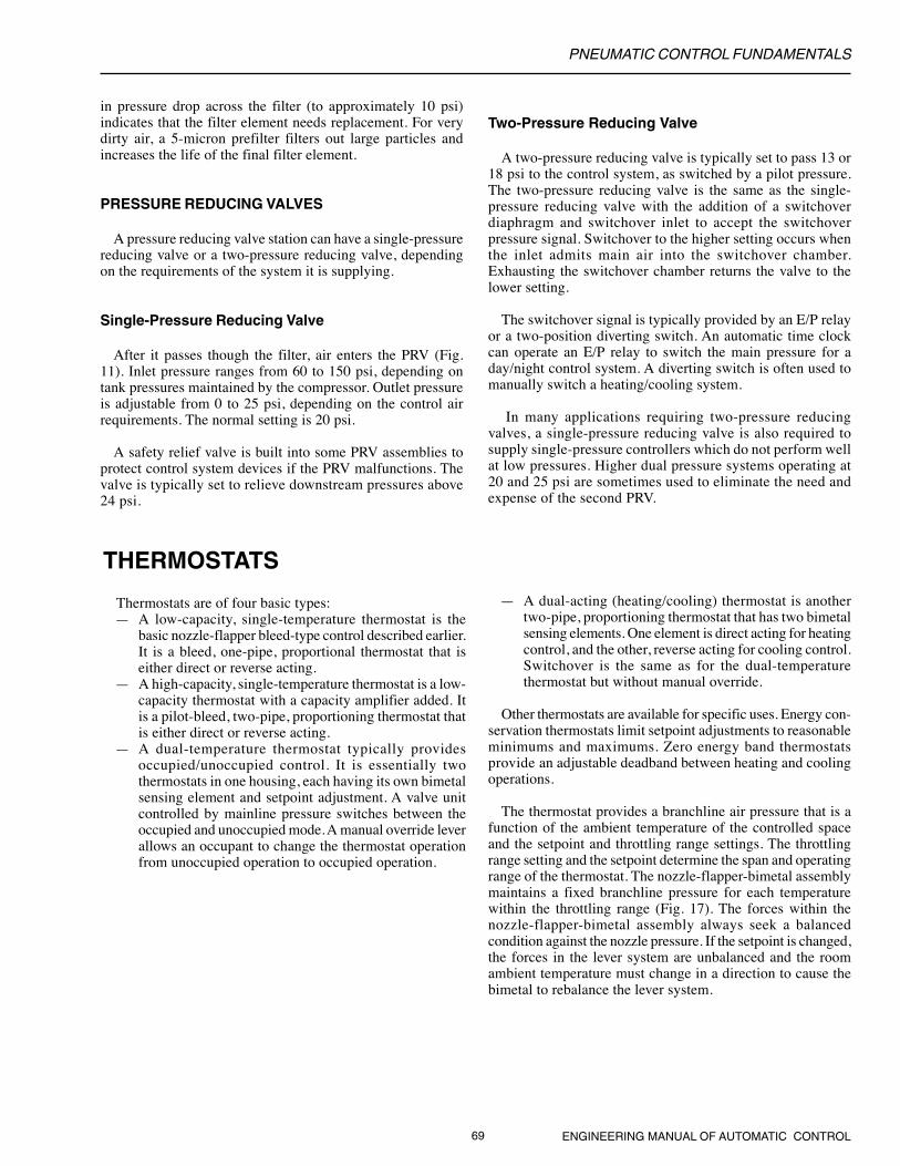
The controlling pressure is connected at the pilot port (P),and pressures to be switched are connected at the normallyconnected port (O) or the normally disconnected port (X).The operating point of the relay is set by adjusting the springpressure at the top of the relay.
When the pressure at the pilot port reaches the relayoperating point, it pushes up on the diaphragm in the controlchamber and connects pressure on the normallydisconnected port (X) to the common port as shown. If thepilot pressure falls below the relay setpoint, the diaphragmmoves down, blocks the normally disconnected (X) port,and connects the normally connected port (O) to the commonport.
GENERAL
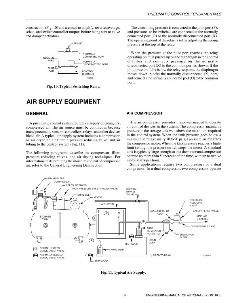
A pneumatic control system requires a supply of clean, dry,compressed air. The air source must be continuous becausemany pneumatic sensors, controllers, relays, and other devicesbleed air. A typical air supply system includes a compressor,an air dryer, an air filter, a pressure reducing valve, and airtubing to the control system (Fig. 11).
The following paragraphs describe the compressor, filter,pressure reducing valves, and air drying techniques. Forinformation on determining the moisture content of compressedair, refer to the General Engineering Data section.
AIR COMPRESSOR
The air compressor provides the power needed to operateall control devices in the system. The compressor maintainspressure in the storage tank well above the maximum requiredin the control system. When the tank pressure goes below aminimum setting (usually 70 to 90 psi), a pressure switch startsthe compressor motor. When the tank pressure reaches a high-limit setting, the pressure switch stops the motor. A standardtank is typically large enough so that the motor and compressoroperate no more than 50 percent of the time, with up to twelvemotor starts per hour.
Some applications require two compressors or a dualcompressor. In a dual compressor, two compressors operate
AIR SUPPLY EQUIPMENT
PNEUMATIC CONTROL FUNDAMENTALS
ENGINEERING MANUAL OF AUTOMATIC CONTROL 66
alternately, so wear is spread over both machines, each capableof supplying the average requirements of the system withoutoperating more than half the time. In the event of failure ofone compressor, the other assumes the full load.
Contamination in the atmosphere requires a compressorintake filter to remove particles that would damage thecompressor pump. The filter is essential on oil-less compressorsbecause a contaminated inlet air can cause excessive wear onpiston rings. The intake filter is usually located in the equipmentroom with the compressor, but it may be located outdoors ifclean outdoor air is available. After the air is compressed,cooling and settling actions in the tank condense some of theexcess moisture and allow fallout of the larger oil dropletsgenerated by the compressor pump.
A high pressure safety relief valve which opens onexcessively high tank pressures is also required. A hand valveor automatic trap periodically blows off any accumulatedmoisture, oil residue, or other impurities that collect in thebottom of the tank.
AIR DRYING TECHNIQUES
GENERAL
Air should be dry enough to prevent condensation. Con-densation causes corrosion that can block orifices and valvemechanisms. In addition, dry air improves the ability of filtersto remove oil and dirt.
Moisture in compressed air is removed by increasingpressure, decreasing temperature, or both. When air iscompressed and cooled below its saturation point, moisturecondenses. Draining the condensate from the storage tankcauses some drying of the air supply, but an air dryer is oftenrequired.
An air dryer is selected according to the amount of moisturein the air and the lowest temperature to which an air line willbe exposed. For a chart showing temperature and moisturecontent relationships at various air pressures, refer to theGeneral Engineering Data section.
DRY AIR REQUIREMENT
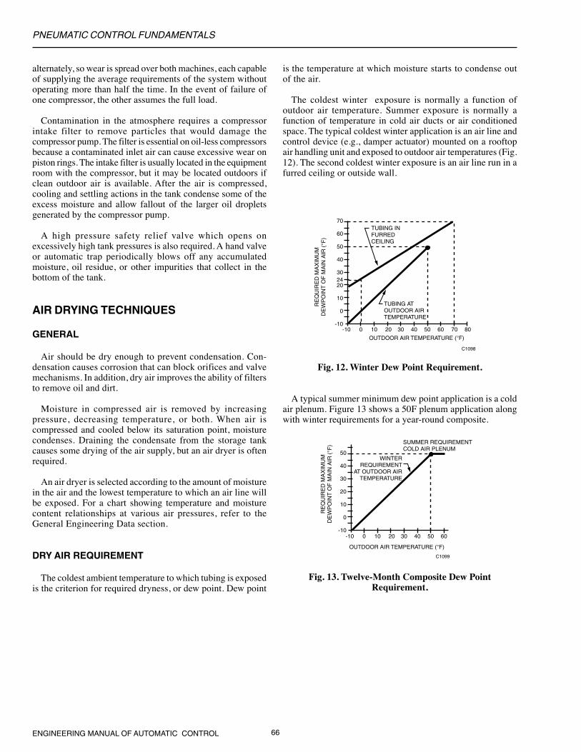
The coldest ambient temperature to which tubing is exposedis the criterion for required dryness, or dew point. Dew point
is the temperature at which moisture starts to condense outof the air.
The coldest winter exposure is normally a function ofoutdoor air temperature. Summer exposure is normally afunction of temperature in cold air ducts or air conditionedspace. The typical coldest winter application is an air line andcontrol device (e.g., damper actuator) mounted on a rooftopair handling unit and exposed to outdoor air temperatures (Fig.12). The second coldest winter exposure is an air line run in afurred ceiling or outside wall.
70
60
50
40
30
20
10
0
-10-10 0 10 20 30 40 50 60 70 80
C1098
OUTDOOR AIR TEMPERATURE (°F)
RE
QU
IRE
D M
AX
IMU
MD
EW
PO
INT
OF
MA
IN A
IR (°F
)
24
TUBING IN FURRED CEILING
TUBING ATOUTDOOR AIR TEMPERATURE
Fig. 12. Winter Dew Point Requirement.
A typical summer minimum dew point application is a coldair plenum. Figure 13 shows a 50F plenum application alongwith winter requirements for a year-round composite.
50
40
30
20
10
0
-10-10 0 10 20 30 40 50 60
C1099
OUTDOOR AIR TEMPERATURE (°F)
RE
QU
IRE
D M
AX
IMU
MD
EW
PO
INT
OF
MA
IN A
IR (°F
) SUMMER REQUIREMENTCOLD AIR PLENUM
WINTER REQUIREMENT
AT OUTDOOR AIRTEMPERATURE
Fig. 13. Twelve-Month Composite Dew PointRequirement.
PNEUMATIC CONTROL FUNDAMENTALS
67 ENGINEERING MANUAL OF AUTOMATIC CONTROL
CONDENSING DRYING
The two methods of condensing drying are high-pressuredrying and refrigerant drying.
High-Pressure Drying
High-pressure drying may be used when main air piping iskept away from outside walls and chilling equipment. Duringcompression and cooling to ambient temperatures, air givesup moisture which then collects in the bottom of the storagetank. The higher the tank pressure, the greater the amount ofmoisture that condenses. Maintaining a high pressure removesthe maximum amount of moisture. The compressor should havea higher operating pressure than is required for air supplypurposes only. However, higher air pressure requires moreenergy to run the compressor. The tank must include a manualdrain valve or an automatic trap to continually drain offaccumulated moisture. With tank pressures of 70 to 90 psi, adew point of approximately 70F at 20 psi can be obtained.
Refrigerant Drying
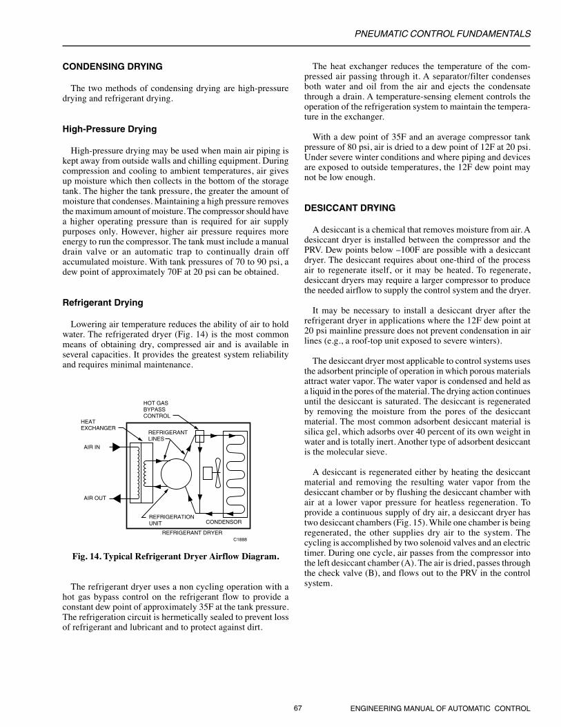
Lowering air temperature reduces the ability of air to holdwater. The refrigerated dryer (Fig. 14) is the most commonmeans of obtaining dry, compressed air and is available inseveral capacities. It provides the greatest system reliabilityand requires minimal maintenance.
The heat exchanger reduces the temperature of the com-pressed air passing through it. A separator/filter condensesboth water and oil from the air and ejects the condensatethrough a drain. A temperature-sensing element controls theoperation of the refrigeration system to maintain the tempera-ture in the exchanger.
With a dew point of 35F and an average compressor tankpressure of 80 psi, air is dried to a dew point of 12F at 20 psi.Under severe winter conditions and where piping and devicesare exposed to outside temperatures, the 12F dew point maynot be low enough.
DESICCANT DRYING
A desiccant is a chemical that removes moisture from air. Adesiccant dryer is installed between the compressor and thePRV. Dew points below –100F are possible with a desiccantdryer. The desiccant requires about one-third of the processair to regenerate itself, or it may be heated. To regenerate,desiccant dryers may require a larger compressor to producethe needed airflow to supply the control system and the dryer.
It may be necessary to install a desiccant dryer after therefrigerant dryer in applications where the 12F dew point at20 psi mainline pressure does not prevent condensation in airlines (e.g., a roof-top unit exposed to severe winters).
The desiccant dryer most applicable to control systems usesthe adsorbent principle of operation in which porous materialsattract water vapor. The water vapor is condensed and held asa liquid in the pores of the material. The drying action continuesuntil the desiccant is saturated. The desiccant is regeneratedby removing the moisture from the pores of the desiccantmaterial. The most common adsorbent desiccant material issilica gel, which adsorbs over 40 percent of its own weight inwater and is totally inert. Another type of adsorbent desiccantis the molecular sieve.
A desiccant is regenerated either by heating the desiccantmaterial and removing the resulting water vapor from thedesiccant chamber or by flushing the desiccant chamber withair at a lower vapor pressure for heatless regeneration. Toprovide a continuous supply of dry air, a desiccant dryer hastwo desiccant chambers (Fig. 15). While one chamber is beingregenerated, the other supplies dry air to the system. Thecycling is accomplished by two solenoid valves and an electrictimer. During one cycle, air passes from the compressor intothe left desiccant chamber (A). The air is dried, passes throughthe check valve (B), and flows out to the PRV in the controlsystem.
HOT GASBYPASS CONTROL
HEATEXCHANGER
AIR IN
AIR OUT
REFRIGERANTLINES
REFRIGERATIONUNIT CONDENSOR
REFRIGERANT DRYERC1888
Fig. 14. Typical Refrigerant Dryer Airflow Diagram.
The refrigerant dryer uses a non cycling operation with ahot gas bypass control on the refrigerant flow to provide aconstant dew point of approximately 35F at the tank pressure.The refrigeration circuit is hermetically sealed to prevent lossof refrigerant and lubricant and to protect against dirt.

PNEUMATIC CONTROL FUNDAMENTALS
ENGINEERING MANUAL OF AUTOMATIC CONTROL 68
Fig. 15. Typical Heatless DesiccantDryer Airflow Diagram.
Simultaneously, some of the dried air passes through theorifice (G) to the right desiccant chamber (E). The air is dryand the desiccant chamber is open to the atmosphere, whichreduces the chamber pressure to near atmospheric pressure.Reducing the air pressure lowers the vapor pressure of the airbelow that of the desiccant, which allows the moisture totransfer from the desiccant to the air. The timer controls thecycle, which lasts approximately 30 minutes.
During the cycle, the desiccant in the left chamber (A)becomes saturated, and the desiccant in the right chamber (E)becomes dry. The timer then reverses the flow by switchingboth of the solenoid valves (D and H). The desiccant in theright chamber (E) then becomes the drying agent connected tothe compressor while the desiccant in the left chamber (A) isdried.
The process provides dry air to the control system continuallyand requires no heat to drive moisture from the desiccant. Afine filter should be used after the desiccant dryer to filter outany desiccant discharged into the air supply.
C1889
DESICCANTCHAMBERS
CHECKVALVE
CHECKVALVE
ORIFICE ORIFICE
SOLENOID
A
B C
D
DRY AIR OUT
H
GF
E
AIR FROM COMPRESSOR
SOLENOID
PRESSURE REDUCING VALVE STATION
The pressure reducing valve station is typically furnishedwith an air filter. The filter, high-pressure gage, high pressurerelief valve, pressure reducing valve (PRV), and low-pressuregage are usually located together at one point in the systemand may be mounted directly on the compressor. The mostimportant elements are the air filter and the PRV.
AIR FILTER
The air filter (Fig. 16) removes solid particulate matter andoil aerosols or mist from the control air.
AIR INAIR OUT
INNER FOAMSLEEVE
FILTERINGMEDIUM
OUTER FOAMSLEEVE
PERFORATEDMETALCYLINDER
LIQUID DRAIN C2601
Fig. 16. Typical Air Filter.
Oil contamination in compressed air appears as a gas or anaerosol. Gaseous oil usually remains in a vapor state throughoutthe system and does not interfere with operation of thecontrols. Aerosols, however, can coalesce while flowingthrough the system, and turbulence can cause particles tocollect in device filters, orifices, and small passages.
Many filters are available to remove solids from the air.However, only an oil-coalescing filter can remove oil aerosolsfrom control air. An oil coalescing filter uses a bonded fibrousmaterial to combine the small particles of oil mist into largerdroplets. The coalesced liquids and solids gravitate to thebottom of the outer surface of the filter material, drop off intoa sump, and are automatically discharged or manually drained.
The oil coalescing filter continues to coalesce and drain offaccumulated oil until solid particles plug the filter. An increase
PNEUMATIC CONTROL FUNDAMENTALS
69 ENGINEERING MANUAL OF AUTOMATIC CONTROL
in pressure drop across the filter (to approximately 10 psi)indicates that the filter element needs replacement. For verydirty air, a 5-micron prefilter filters out large particles andincreases the life of the final filter element.
PRESSURE REDUCING VALVES
A pressure reducing valve station can have a single-pressurereducing valve or a two-pressure reducing valve, dependingon the requirements of the system it is supplying.
Single-Pressure Reducing Valve
After it passes though the filter, air enters the PRV (Fig.11). Inlet pressure ranges from 60 to 150 psi, depending ontank pressures maintained by the compressor. Outlet pressureis adjustable from 0 to 25 psi, depending on the control airrequirements. The normal setting is 20 psi.
A safety relief valve is built into some PRV assemblies toprotect control system devices if the PRV malfunctions. Thevalve is typically set to relieve downstream pressures above24 psi.
Two-Pressure Reducing Valve
A two-pressure reducing valve is typically set to pass 13 or18 psi to the control system, as switched by a pilot pressure.The two-pressure reducing valve is the same as the single-pressure reducing valve with the addition of a switchoverdiaphragm and switchover inlet to accept the switchoverpressure signal. Switchover to the higher setting occurs whenthe inlet admits main air into the switchover chamber.Exhausting the switchover chamber returns the valve to thelower setting.
The switchover signal is typically provided by an E/P relayor a two-position diverting switch. An automatic time clockcan operate an E/P relay to switch the main pressure for aday/night control system. A diverting switch is often used tomanually switch a heating/cooling system.
In many applications requiring two-pressure reducingvalves, a single-pressure reducing valve is also required tosupply single-pressure controllers which do not perform wellat low pressures. Higher dual pressure systems operating at20 and 25 psi are sometimes used to eliminate the need andexpense of the second PRV.
Thermostats are of four basic types:— A low-capacity, single-temperature thermostat is the
basic nozzle-flapper bleed-type control described earlier.It is a bleed, one-pipe, proportional thermostat that iseither direct or reverse acting.
— A high-capacity, single-temperature thermostat is a low-capacity thermostat with a capacity amplifier added. Itis a pilot-bleed, two-pipe, proportioning thermostat thatis either direct or reverse acting.
— A dual-temperature thermostat typically providesoccupied/unoccupied control. It is essentially twothermostats in one housing, each having its own bimetalsensing element and setpoint adjustment. A valve unitcontrolled by mainline pressure switches between theoccupied and unoccupied mode. A manual override leverallows an occupant to change the thermostat operationfrom unoccupied operation to occupied operation.
— A dual-acting (heating/cooling) thermostat is anothertwo-pipe, proportioning thermostat that has two bimetalsensing elements. One element is direct acting for heatingcontrol, and the other, reverse acting for cooling control.Switchover is the same as for the dual-temperaturethermostat but without manual override.
Other thermostats are available for specific uses. Energy con-servation thermostats limit setpoint adjustments to reasonableminimums and maximums. Zero energy band thermostatsprovide an adjustable deadband between heating and coolingoperations.
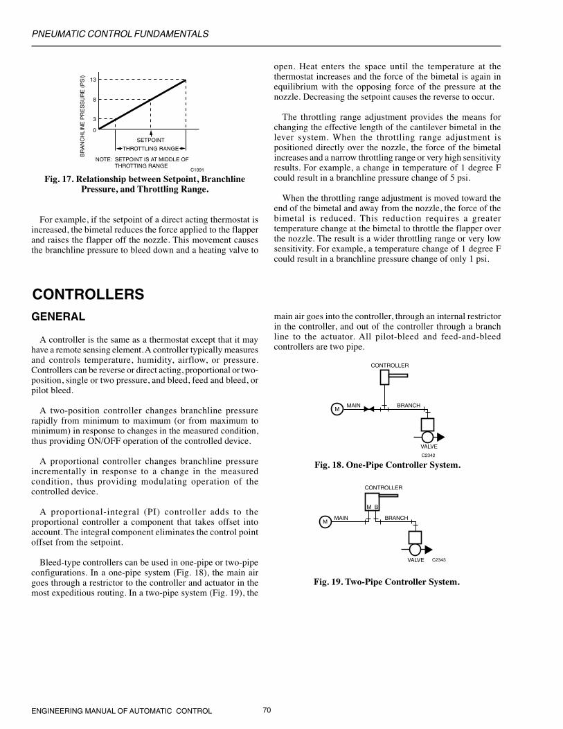
The thermostat provides a branchline air pressure that is afunction of the ambient temperature of the controlled spaceand the setpoint and throttling range settings. The throttlingrange setting and the setpoint determine the span and operatingrange of the thermostat. The nozzle-flapper-bimetal assemblymaintains a fixed branchline pressure for each temperaturewithin the throttling range (Fig. 17). The forces within thenozzle-flapper-bimetal assembly always seek a balancedcondition against the nozzle pressure. If the setpoint is changed,the forces in the lever system are unbalanced and the roomambient temperature must change in a direction to cause thebimetal to rebalance the lever system.
THERMOSTATS
PNEUMATIC CONTROL FUNDAMENTALS
ENGINEERING MANUAL OF AUTOMATIC CONTROL 70
Fig. 18. One-Pipe Controller System.C2342
MAIN BRANCH
VALVE
CONTROLLER
M
C2343
MAIN BRANCH
VALVE
CONTROLLER
M B
M
THROTTLING RANGE
0
3
8
13
SETPOINT
NOTE: SETPOINT IS AT MIDDLE OF THROTTING RANGE
BR
AN
CH
LIN
E P
RE
SS
UR
E (
PS
I)
C1091
Fig. 17. Relationship between Setpoint, BranchlinePressure, and Throttling Range.
For example, if the setpoint of a direct acting thermostat isincreased, the bimetal reduces the force applied to the flapperand raises the flapper off the nozzle. This movement causesthe branchline pressure to bleed down and a heating valve to
open. Heat enters the space until the temperature at thethermostat increases and the force of the bimetal is again inequilibrium with the opposing force of the pressure at thenozzle. Decreasing the setpoint causes the reverse to occur.
The throttling range adjustment provides the means forchanging the effective length of the cantilever bimetal in thelever system. When the throttling range adjustment ispositioned directly over the nozzle, the force of the bimetalincreases and a narrow throttling range or very high sensitivityresults. For example, a change in temperature of 1 degree Fcould result in a branchline pressure change of 5 psi.
When the throttling range adjustment is moved toward theend of the bimetal and away from the nozzle, the force of thebimetal is reduced. This reduction requires a greatertemperature change at the bimetal to throttle the flapper overthe nozzle. The result is a wider throttling range or very lowsensitivity. For example, a temperature change of 1 degree Fcould result in a branchline pressure change of only 1 psi.
GENERAL
A controller is the same as a thermostat except that it mayhave a remote sensing element. A controller typically measuresand controls temperature, humidity, airflow, or pressure.Controllers can be reverse or direct acting, proportional or two-position, single or two pressure, and bleed, feed and bleed, orpilot bleed.
A two-position controller changes branchline pressurerapidly from minimum to maximum (or from maximum tominimum) in response to changes in the measured condition,thus providing ON/OFF operation of the controlled device.
A proportional controller changes branchline pressureincrementally in response to a change in the measuredcondition, thus providing modulating operation of thecontrolled device.
A proportional-integral (PI) controller adds to theproportional controller a component that takes offset intoaccount. The integral component eliminates the control pointoffset from the setpoint.
Bleed-type controllers can be used in one-pipe or two-pipeconfigurations. In a one-pipe system (Fig. 18), the main airgoes through a restrictor to the controller and actuator in themost expeditious routing. In a two-pipe system (Fig. 19), the
main air goes into the controller, through an internal restrictorin the controller, and out of the controller through a branchline to the actuator. All pilot-bleed and feed-and-bleedcontrollers are two pipe.
Fig. 19. Two-Pipe Controller System.
CONTROLLERS
PNEUMATIC CONTROL FUNDAMENTALS
71 ENGINEERING MANUAL OF AUTOMATIC CONTROL
Controllers may also be classified as single-pressure or two-pressure controllers. Single-pressure controllers use a constantmain air pressure. Two-pressure controllers use a main airpressure that is alternately switched between two pressures,such as 13 and 18 psi. For example, occupied/unoccupiedcontrollers automatically change setpoint from a occupiedsetting at a mainline pressure of 13 psi to a lowered unoccupiedsetting at 18 psi. Heating/cooling controllers change fromreverse acting at mainline air pressure of 13 psi for cooling todirect acting at 18 psi for heating.
TEMPERATURE CONTROLLERS
Temperature controllers can be one- or two-pipe. The sensingelement is typically bimetal, liquid filled remote bulb, or liquidfilled averaging capillary tube. Dimensional change of theelement with temperature change results in flapper positionchange and therefore, pilot and branch pressure change.
HUMIDITY CONTROLLERS
Principles that apply to temperature controllers also applyto humidity controllers. The primary difference betweentemperature and humidity controllers is in the type of sensingelement. The sensing element in a humidistat is usually a bandof moisture-sensitive nylon. The nylon expands and contractswith changes in the relative humidity of the air.
The humidistat can be used in a one-pipe or two-pipeconfiguration and is available as either a bleed-type humidistator a two-pipe capacity humidistat using a capacity amplifier.The humidistat may be direct or reverse acting. The high-capacity humidistat has a capacity amplifier.
PRESSURE CONTROLLERS
Pressure controllers can be divided into two classesaccording to the pressure range of the measured variable. High-pressure controllers measure and control high pressures orvacuums measured in pounds per square inch or in inches ofmercury (e.g., steam or water pressures in an air conditioningsystem). Low-pressure controllers measure and control lowpressures and vacuums measured in inches of water (e.g.,pressure in an air duct).
High- and low-pressure controllers have different sizediaphragms. In both types, one side of the diaphragm isconnected to the pressure to be controlled, and the other sideis connected to a reference pressure. Pressures can be measured
in respect to atmospheric pressure or another pressure source.The low-pressure controller is available in both bleed-type andpilot-bleed designs.
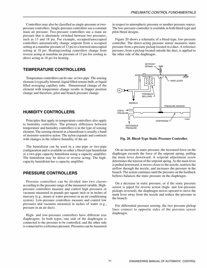
Figure 20 shows a schematic of a bleed-type, low-pressurecontroller. The direct-acting pressure sensor measures staticpressure from a pressure pickup located in a duct. A referencepressure, from a pickup located outside the duct, is applied tothe other side of the diaphragm.
PRESSURE SENSOR
REFERENCEPRESSURE
STATICPRESSURE
C2609
SETPOINTSPRING
DIAPHRAGM
M
BRANCH
FEEDBACKBELLOWS
MAIN LEVER
Fig. 20. Bleed-Type Static Pressure Controller.
On an increase in static pressure, the increased force on thediaphragm exceeds the force of the setpoint spring, pullingthe main lever downward. A setpoint adjustment screwdetermines the tension of the setpoint spring. As the main leveris pulled downward, it moves closer to the nozzle, restricts theairflow through the nozzle, and increases the pressure in thebranch. The action continues until the pressure on the feedbackbellows balances the static pressure on the diaphragm.
On a decrease in static pressure, or if the static pressuresensor is piped for reverse action (high- and low-pressurepickups reversed), the diaphragm moves upward to move themain lever away from the nozzle and reduce the pressure inthe branch.
For differential pressure sensing, the two pressure pickuplines connect to opposite sides of the pressure sensordiaphragm.
PNEUMATIC CONTROL FUNDAMENTALS
ENGINEERING MANUAL OF AUTOMATIC CONTROL 72
SENSOR-CONTROLLER SYSTEMS
A sensor-controller system is made up of a pneumaticcontroller, remote pneumatic sensors, and a final controlelement. The controller provides proportional or proportional-integral control of temperature, humidity, dew point, or pressurein HVAC systems. Sensors do not have a setpoint adjustmentand provide a linear 3 to 15 psi signal to the controller over afixed sensor range. The controller compares the sensor inputsignal with the setpoint signal. The difference is the pilot inputto a signal amplifier, which provides a branchline pressure tothe controlled device. Thus the controller acts as a general-purpose pneumatic amplifier.
PNEUMATIC CONTROLLERS
Controllers generally use diaphragm logic, which allowsflexible system application, provides more accurate control,and simplifies setup and adjustment for the needs of eachsystem. Controllers may be proportional only or proportional-integral (PI). The integral function is also called “automaticreset”. Proportional and PI controllers are available with single-sensor input or dual-sensor input for resetting the primarysensor setpoint from a second sensor. They are also availablewith integral or remote setpoint adjustment.
The single-input controller consists of a signal amplifierfeeding a capacity amplifier. The capacity amplifier is discussedunder PILOT BLEED SYSTEM. A dual-input controller hasinputs from a primary temperature sensor and a resettemperature sensor. The reset sensor resets controller setpoint.Reset can be negative or positive.
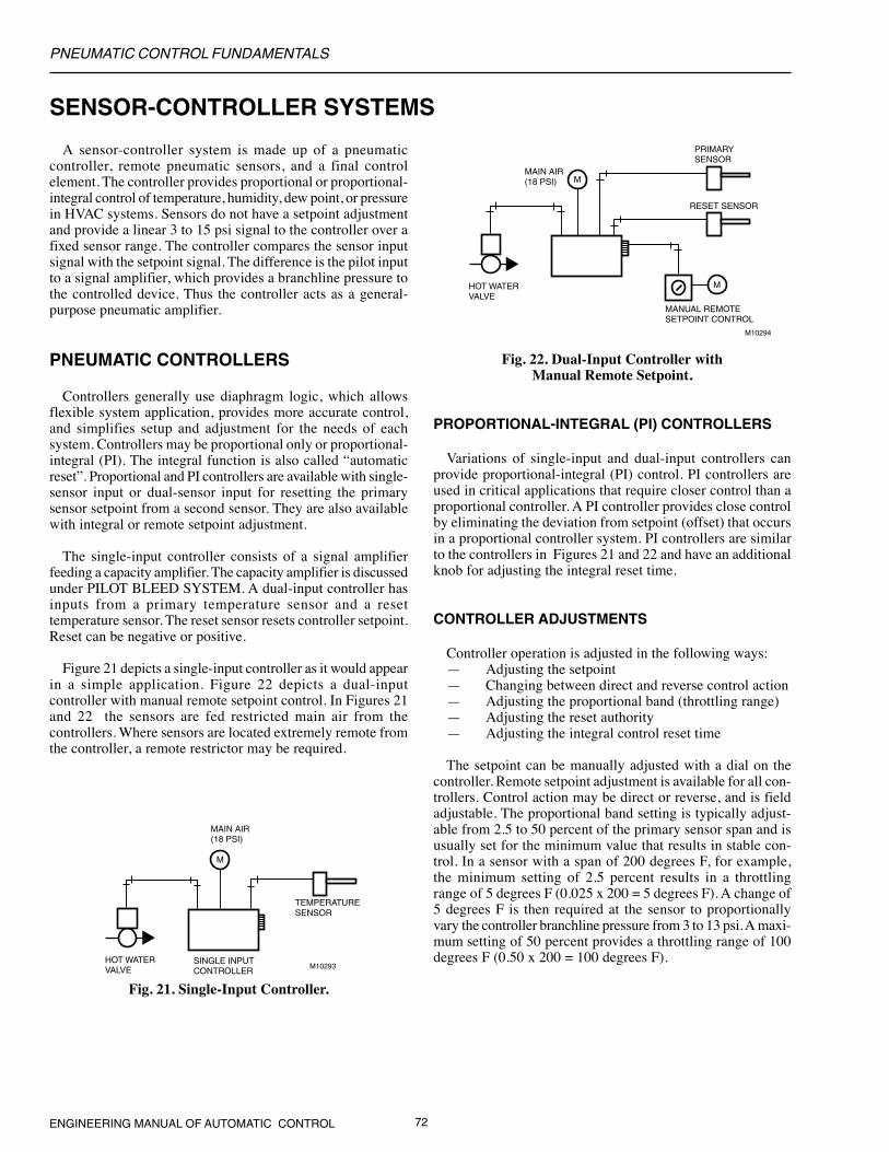
Figure 21 depicts a single-input controller as it would appearin a simple application. Figure 22 depicts a dual-inputcontroller with manual remote setpoint control. In Figures 21and 22 the sensors are fed restricted main air from thecontrollers. Where sensors are located extremely remote fromthe controller, a remote restrictor may be required.
Fig. 22. Dual-Input Controller withManual Remote Setpoint.
PROPORTIONAL-INTEGRAL (PI) CONTROLLERS
Variations of single-input and dual-input controllers canprovide proportional-integral (PI) control. PI controllers areused in critical applications that require closer control than aproportional controller. A PI controller provides close controlby eliminating the deviation from setpoint (offset) that occursin a proportional controller system. PI controllers are similarto the controllers in Figures 21 and 22 and have an additionalknob for adjusting the integral reset time.
CONTROLLER ADJUSTMENTS
Controller operation is adjusted in the following ways:— Adjusting the setpoint— Changing between direct and reverse control action— Adjusting the proportional band (throttling range)— Adjusting the reset authority— Adjusting the integral control reset time
The setpoint can be manually adjusted with a dial on thecontroller. Remote setpoint adjustment is available for all con-trollers. Control action may be direct or reverse, and is fieldadjustable. The proportional band setting is typically adjust-able from 2.5 to 50 percent of the primary sensor span and isusually set for the minimum value that results in stable con-trol. In a sensor with a span of 200 degrees F, for example,the minimum setting of 2.5 percent results in a throttlingrange of 5 degrees F (0.025 x 200 = 5 degrees F). A change of5 degrees F is then required at the sensor to proportionallyvary the controller branchline pressure from 3 to 13 psi. A maxi-mum setting of 50 percent provides a throttling range of 100degrees F (0.50 x 200 = 100 degrees F).
M
SINGLE INPUTCONTROLLER
HOT WATERVALVE
MAIN AIR (18 PSI)
TEMPERATURESENSOR
M10293
Fig. 21. Single-Input Controller.
M
MANUAL REMOTESETPOINT CONTROL
HOT WATERVALVE
MAIN AIR(18 PSI)
RESET SENSOR
PRIMARYSENSOR
M10294
M

PNEUMATIC CONTROL FUNDAMENTALS
73 ENGINEERING MANUAL OF AUTOMATIC CONTROL
Reset authority, also called “reset ratio”, is the ratio of theeffect of the reset sensor compared to the primary sensor.Figure 23 shows the effect of authority on a typical resetschedule. The authority can be set from 10 to 300 percent.
DA
TE
MP
ER
ATU
RE
C
ON
TR
OL
PO
INT
(°F
)
OUTDOOR AIR TEMPERATURE (°F)
COMPENSATIONSTART POINT
600
30
130
C1094
Fig. 23. Typical Reset Schedule forDischarge Air Control.
The integral control reset time determines how quickly thePI controller responds to a change in the controlled variable.Proportional correction occurs as soon as the controlledvariable changes. The integral function is timed with the resettime adjustment. The reset time adjustment is calibrated from30 seconds to 20 minutes. The proper setting depends onsystem response time characteristics.
PNEUMATIC SENSORS
Pneumatic sensors typically provide a direct acting 3 to 15 psipneumatic output signal that is proportional to the measuredvariable. Any change in the measured variable is reflected as achange in the sensor output. Commonly sensed variables aretemperature, humidity, and differential pressure. The sensorsuse the same sensing elements and principles as the sensors inthe controllers described earlier, but do not include setpointand throttling range adjustments. Their throttling range is thesame as their span.
A gage connected to the sensor output can be used to indicatethe temperature, humidity, or pressure being sensed. The gagescale is calibrated to the sensor span.
Temperature sensors may be vapor-filled, liquid-filled,averaging capillary, or rod-and-tube. The controller usuallyprovides restricted air to the sensor.
Humidity sensors measure the relative humidity of the airin a room (wall-mounted element) or a duct (insertion element).Nylon is typically used as the sensing element. Humiditysensors include temperature compensation and operate on aforce-balance principle similar to a wall thermostat.
The low-pressure sensor measures duct static pressure anddifferential pressure. When the duct static pressure or thepressure differential increases, branchline pressure increases.
VELOCITY SENSOR-CONTROLLER
The velocity sensor-controller combines a highly sensitiveair velocity sensor with a pneumatic controller to detect andcontrol airflow regardless of system static pressure. It is usedin air terminal units and other air handling systems. Reverse-and direct-acting models are available for normally closed andnormally open dampers.
The velocity sensor measures actual velocity and does notrequire the conversion of velocity pressure to velocity.Although the sensor is typically used in duct air velocityapplications, it can accurately sense velocities as low as 100feet per minute. Flow-limiting orifices inserted into the sensorsampling tube can measure velocity ranges up to 3,500 feetper minute.
Figure 24 shows the operation of a velocity sensor. Arestrictor supplies compressed air to the emitter tube locatedin the air stream to be measured. When no air is flowing in theduct, the jet of air from the emitter tube impinges directly onthe collector tube and maximum pressure is sensed. Air flowingin the duct blows the air jet downstream and reduces thepressure on the collector tube. As the duct air velocity increases,less and less of the jet enters the collector tube. The collectortube is connected to a pressure amplifier to produce a usableoutput pressure and provide direct or reverse action.
M
AIR FLOW
EMITTER TUBE
GAP
COLLECTORTUBE
TO PRESSUREAMPLIFIER
C2610
Fig. 24. Velocity Sensor Operation.
A controller connected to the pressure amplifier includessetpoints for maximum and minimum dual air velocity limits.This allows the air volume to be controlled between the limitsby a thermostat or another controller.
Two models of the controller are available. One modeloperates with a one-pipe, bleed-type thermostat, and the otherwith a two-pipe thermostat. The two-pipe model also allowssequencing for reheat applications.
PNEUMATIC CONTROL FUNDAMENTALS
ENGINEERING MANUAL OF AUTOMATIC CONTROL 74
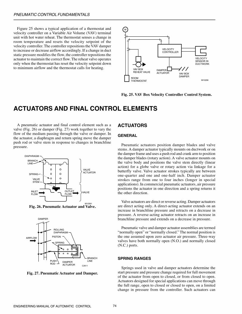
Figure 25 shows a typical application of a thermostat andvelocity controller on a Variable Air Volume (VAV) terminalunit with hot water reheat. The thermostat senses a change inroom temperature and resets the velocity setpoint of thevelocity controller. The controller repositions the VAV damperto increase or decrease airflow accordingly. If a change in ductstatic pressure modifies the flow, the controller repositions theactuator to maintain the correct flow. The reheat valve operatesonly when the thermostat has reset the velocity setpoint downto minimum airflow and the thermostat calls for heating.
M
VELOCITYSENSOR INDUCTWORK
VAV BOXDAMPER
DAMPERACTUATOR
VELOCITYCONTROLLER
VAV BOXREHEAT VALVE
ROOMTHERMOSTAT M10296
Fig. 25. VAV Box Velocity Controller Control System.
ACTUATORS AND FINAL CONTROL ELEMENTS
A pneumatic actuator and final control element such as avalve (Fig. 26) or damper (Fig. 27) work together to vary theflow of the medium passing through the valve or damper. Inthe actuator, a diaphragm and return spring move the damperpush rod or valve stem in response to changes in branchlinepressure.
Fig. 26. Pneumatic Actuator and Valve.
C2611
DAMPER
AIRFLOW
PUSHROD
DAMPERACTUATOR
SPRING
PISTON
ROLLINGDIAPHRAGM
BRANCHLINE
Fig. 27. Pneumatic Actuator and Damper.
ACTUATORS
GENERAL
Pneumatic actuators position damper blades and valvestems. A damper actuator typically mounts on ductwork or onthe damper frame and uses a push rod and crank arm to positionthe damper blades (rotary action). A valve actuator mounts onthe valve body and positions the valve stem directly (linearaction) for a globe valve or rotary action via linkage for abutterfly valve. Valve actuator strokes typically are betweenone-quarter and one and one-half inch. Damper actuatorstrokes range from one to four inches (longer in specialapplications). In commercial pneumatic actuators, air pressurepositions the actuator in one direction and a spring returns itthe other direction.
Valve actuators are direct or reverse acting. Damper actuatorsare direct acting only. A direct-acting actuator extends on anincrease in branchline pressure and retracts on a decrease inpressure. A reverse-acting actuator retracts on an increase inbranchline pressure and extends on a decrease in pressure.
Pneumatic valve and damper actuator assemblies are termed“normally open” or “normally closed.” The normal position isthe one assumed upon zero actuator air pressure. Three-wayvalves have both normally open (N.O.) and normally closed(N.C.) ports.
SPRING RANGES
Springs used in valve and damper actuators determine thestart pressure and pressure change required for full movementof the actuator from open to closed, or from closed to open.Actuators designed for special applications can move throughthe full range, open to closed or closed to open, on a limitedchange in pressure from the controller. Such actuators can
BRANCH LINE
SPRING
VALVESTEM
INLETFLOW
OUTLET FLOW
DIAPHRAGM
VALVEACTUATOR
VALVE
M10361
PNEUMATIC CONTROL FUNDAMENTALS
75 ENGINEERING MANUAL OF AUTOMATIC CONTROL
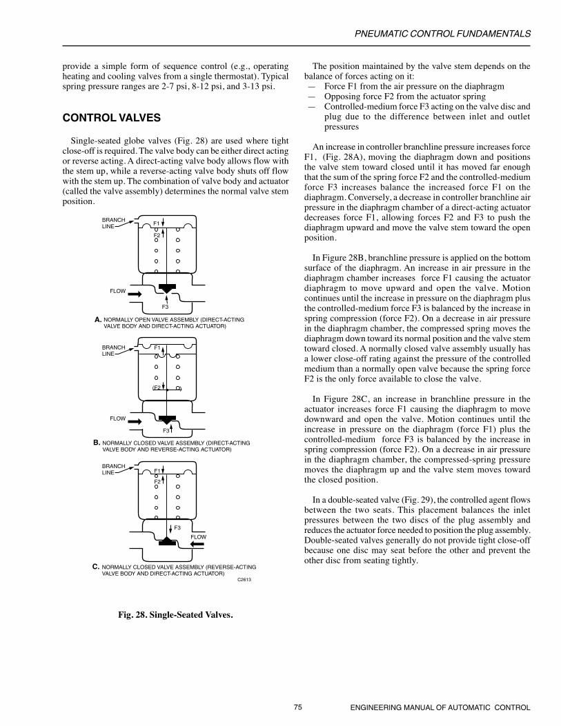
provide a simple form of sequence control (e.g., operatingheating and cooling valves from a single thermostat). Typicalspring pressure ranges are 2-7 psi, 8-12 psi, and 3-13 psi.
CONTROL VALVES
Single-seated globe valves (Fig. 28) are used where tightclose-off is required. The valve body can be either direct actingor reverse acting. A direct-acting valve body allows flow withthe stem up, while a reverse-acting valve body shuts off flowwith the stem up. The combination of valve body and actuator(called the valve assembly) determines the normal valve stemposition.
Fig. 28. Single-Seated Valves.
The position maintained by the valve stem depends on thebalance of forces acting on it:— Force F1 from the air pressure on the diaphragm— Opposing force F2 from the actuator spring— Controlled-medium force F3 acting on the valve disc and
plug due to the difference between inlet and outletpressures
An increase in controller branchline pressure increases forceF1, (Fig. 28A), moving the diaphragm down and positionsthe valve stem toward closed until it has moved far enoughthat the sum of the spring force F2 and the controlled-mediumforce F3 increases balance the increased force F1 on thediaphragm. Conversely, a decrease in controller branchline airpressure in the diaphragm chamber of a direct-acting actuatordecreases force F1, allowing forces F2 and F3 to push thediaphragm upward and move the valve stem toward the openposition.
In Figure 28B, branchline pressure is applied on the bottomsurface of the diaphragm. An increase in air pressure in thediaphragm chamber increases force F1 causing the actuatordiaphragm to move upward and open the valve. Motioncontinues until the increase in pressure on the diaphragm plusthe controlled-medium force F3 is balanced by the increase inspring compression (force F2). On a decrease in air pressurein the diaphragm chamber, the compressed spring moves thediaphragm down toward its normal position and the valve stemtoward closed. A normally closed valve assembly usually hasa lower close-off rating against the pressure of the controlledmedium than a normally open valve because the spring forceF2 is the only force available to close the valve.
In Figure 28C, an increase in branchline pressure in theactuator increases force F1 causing the diaphragm to movedownward and open the valve. Motion continues until theincrease in pressure on the diaphragm (force F1) plus thecontrolled-medium force F3 is balanced by the increase inspring compression (force F2). On a decrease in air pressurein the diaphragm chamber, the compressed-spring pressuremoves the diaphragm up and the valve stem moves towardthe closed position.
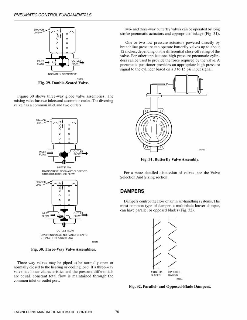
In a double-seated valve (Fig. 29), the controlled agent flowsbetween the two seats. This placement balances the inletpressures between the two discs of the plug assembly andreduces the actuator force needed to position the plug assembly.Double-seated valves generally do not provide tight close-offbecause one disc may seat before the other and prevent theother disc from seating tightly.
BRANCH LINE
FLOW
NORMALLY OPEN VALVE ASSEMBLY (DIRECT-ACTING VALVE BODY AND DIRECT-ACTING ACTUATOR)
C2613
F1
F2
F3
BRANCH LINE
FLOW
NORMALLY CLOSED VALVE ASSEMBLY (DIRECT-ACTING VALVE BODY AND REVERSE-ACTING ACTUATOR)
F1
(F2
F3
)
BRANCH LINE
FLOW
NORMALLY CLOSED VALVE ASSEMBLY (REVERSE-ACTING VALVE BODY AND DIRECT-ACTING ACTUATOR)
F1
F2
F3
A.
B.
C.
PNEUMATIC CONTROL FUNDAMENTALS
ENGINEERING MANUAL OF AUTOMATIC CONTROL 76
Fig. 29. Double-Seated Valve.
Figure 30 shows three-way globe valve assemblies. Themixing valve has two inlets and a common outlet. The divertingvalve has a common inlet and two outlets.
BRANCH LINE
INLETFLOW
OUTLET FLOW
C2612
NORMALLY OPEN VALVE
F3
F2
F1
BRANCH LINE F1
INLETFLOW
INLET FLOW
OUTLET FLOW
OUTLET FLOW
C2615
F2
MIXING VALVE, NORMALLY CLOSED TOSTRAIGHT-THROUGH FLOW
BRANCH LINE F1
INLETFLOW
OUTLET FLOW
F2
DIVERTING VALVE, NORMALLY OPEN TOSTRAIGHT-THROUGH FLOW
Fig. 30. Three-Way Valve Assemblies.
Three-way valves may be piped to be normally open ornormally closed to the heating or cooling load. If a three-wayvalve has linear characteristics and the pressure differentialsare equal, constant total flow is maintained through thecommon inlet or outlet port.
Two- and three-way butterfly valves can be operated by longstroke pneumatic actuators and appropriate linkage (Fig. 31).
One or two low pressure actuators powered directly bybranchline pressure can operate butterfly valves up to about12 inches, depending on the differential close-off rating of thevalve. For other applications high pressure pneumatic cylin-ders can be used to provide the force required by the valve. Apneumatic positioner provides an appropriate high pressuresignal to the cylinder based on a 3 to 15 psi input signal.
PARALLELBLADES
OPPOSEDBLADES
C2604
Fig. 31. Butterfly Valve Assembly.
For a more detailed discussion of valves, see the ValveSelection And Sizing section.
DAMPERS
Dampers control the flow of air in air-handling systems. Themost common type of damper, a multiblade louver damper,can have parallel or opposed blades (Fig. 32).
Fig. 32. Parallel- and Opposed-Blade Dampers.
M10403
PNEUMATIC CONTROL FUNDAMENTALS
77 ENGINEERING MANUAL OF AUTOMATIC CONTROL
Figure 33 shows normally open and normally closed paral-lel-blade dampers. A normally open damper returns to the openposition with low air pressure in the actuator diaphragmchamber. An increase in branchline pressure forces the rollingdiaphragm piston to move against the spring, and a decreaseallows the compressed spring to force the piston and diaphragmback to the normal position. As with valve actuators, interme-diate positions depend on a balance between the force of thecontrol air pressure on the diaphragm and the opposing forceof the actuator spring.
Fig. 33. Normally Open and Normally Closed Dampers.
PILOT SIGNAL BELOWRELAY SETPOINT
PILOT SIGNAL ABOVERELAY SETPOINT
PORTS: P= PILOTC= COMMONO= NORMALLY CONNECTEDX= NORMALLY DISCONNECTED
C2344
P O
C X
P O
C X
C2605
NORMALLY OPEN DAMPER ASSEMBLY
BRANCH LINE BRANCH LINE
ACTUATOR
NORMALLY CLOSED DAMPER ASSEMBLY
ACTUATOR
A normally closed damper returns to the closed position withlow air pressure in the actuator diaphragm chamber. The waythe damper blades, crank arm, and push rod are oriented duringinstallation determines the normal (open or closed) positionof the damper blades.
For a more detailed discussion of dampers, see the DamperSelection and Sizing section.
RELAYS AND SWITCHES
In the following illustrations, common (C) and the normallyconnected port (O) are connected on a fall in pilot pressure (P)below the relay setpoint, and the normally disconnected port(X) is blocked (Fig. 34). On a rise in pilot pressure above therelay setpoint, C and X are connected and O is blocked.
Fig. 34. Relay Port Connections.
SWITCHING RELAY
A switching relay requires a two-position pilot signal and isavailable with either single-pole, double-throw (spdt) ordouble-pole, double-throw (dpdt) switching action. Pneumaticheating and cooling control systems use relays to switch a valveor damper actuator from one circuit to another or to positivelyopen or close a device. Both spdt and dpdt switching relaysare available with a variety of switching pressures.
Figure 35 shows a typical spdt switching relay application forheating/cooling operation in which the thermostat controls theheating/cooling coil valve. Seasonal mainline pressure changescause the action of the thermostat to be reversed. A dischargelow-limit control is switched into the control circuit for heat-ing and out of the circuit for cooling. The switching is donefrom mainline pressure connected to the pilot port (P).
During the heating cycle, the 18 psi mainline pressure isabove the preset switching pressure. The common port (C)connects to the normally disconnected port (X), connectingthe low-limit controller to the thermostat branchline to preventdischarge temperatures below the controller setting. Thenormally connected port (O) is blocked.
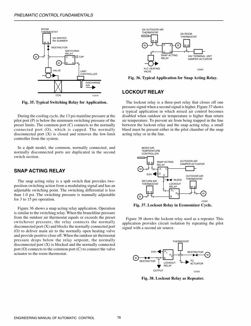
PNEUMATIC CONTROL FUNDAMENTALS
ENGINEERING MANUAL OF AUTOMATIC CONTROL 78
Fig. 35. Typical Switching Relay for Application.
During the cooling cycle, the 13 psi mainline pressure at thepilot port (P) is below the minimum switching pressure of thepreset limits. The common port (C) connects to the normallyconnected port (O), which is capped. The normallydisconnected port (X) is closed and removes the low-limitcontroller from the system.
In a dpdt model, the common, normally connected, andnormally disconnected ports are duplicated in the secondswitch section.
SNAP ACTING RELAY
The snap acting relay is a spdt switch that provides two-position switching action from a modulating signal and has anadjustable switching point. The switching differential is lessthan 1.0 psi. The switching pressure is manually adjustablefor 3 to 15 psi operation.
Figure 36 shows a snap acting relay application. Operationis similar to the switching relay. When the branchline pressurefrom the outdoor air thermostat equals or exceeds the presetswitchover pressure, the relay connects the normallydisconnected port (X) and blocks the normally connected port(O) to deliver main air to the normally open heating valveand provide positive close off. When the outdoor air thermostatpressure drops below the relay setpoint, the normallydisconnected port (X) is blocked and the normally connectedport (O) connects to the common port (C) to connect the valveactuator to the room thermostat.
C2360
SNAP ACTINGRELAY
VAV TERMINAL UNITDAMPER ACTUATOR
N.O. HEATINGVALVE
DA OUTDOOR AIRTHERMOSTAT DA ROOM
THERMOSTAT
M
P
C
X
O
B
M BMM
C2362
SNAP ACTINGRELAY
LOCKOUTRELAY
BLEED
OUTDOOR AIRDAMPER ACTUATOR
MIXED AIRTEMPERATURECONTROLLER
OUTDOOR AIRTHERMOSTAT
M
X
O
C
P
B
M
MM
P1
B
M B
M B P2
EXH
RETURN AIRTHERMOSTAT
Fig. 36. Typical Application for Snap Acting Relay.
LOCKOUT RELAY
The lockout relay is a three-port relay that closes off onepressure signal when a second signal is higher. Figure 37 showsa typical application in which mixed air control becomesdisabled when outdoor air temperature is higher than returnair temperature. To prevent air from being trapped in the linebetween the lockout relay and the snap acting relay, a smallbleed must be present either in the pilot chamber of the snapacting relay or in the line.
LOCKOUTRELAY
P1
BP2 M
M
THERMOSTAT
C2355
TOACTUATOR
OUTPUT
EXH
RESTRICTOR
RESTRICTOR
M B
XP
OC
M
M
ROOMTHERMOSTAT
DA WINTERRA SUMMER
RESTRICTOR
SWITCHING RELAY
CAP
LIMITCONTROLLER
VALVE
COIL
DISCHARGEAIR
C2379
Fig. 37. Lockout Relay in Economizer Cycle.
Figure 38 shows the lockout relay used as a repeater. Thisapplication provides circuit isolation by repeating the pilotsignal with a second air source.
Fig. 38. Lockout Relay as Repeater.

PNEUMATIC CONTROL FUNDAMENTALS
79 ENGINEERING MANUAL OF AUTOMATIC CONTROL
HIGH-PRESSURE SELECTOR RELAY
The high-pressure selector relay is a three-port relay thattransmits the higher of two input signals to the output branch.The high sensitivity of the relay allows it to be used in sensorlines with an accuracy of 2 to 3 degrees F.
The application shown in Figure 39 uses pressures from twozones and a high-pressure selector relay to determine control.A separate thermostat controls each zone damper. Thethermostat that calls for the most cooling (highest branchlinepressure) controls the cooling valve through the high-pressureselector relay.
LOWEST
M
HIGHEST 1 2 3 N
LOAD ANALYZER RELAY
DA ZONE THERMOSTATS
TOZONEDAMPERS
C2369
M B
M
M B
M
M B
M M
M
M B
8-12 PSIN.C. COOLINGVALVE
2-7 PSIN.O. HEATINGVALVE
Fig. 39. Typical Application forHigh-Pressure Selector Relay.
LOW-PRESSURE SELECTOR RELAY
The low-pressure selector relay is a three-port relay thatselects the lower of two input pressure signals and acts as arepeater for the lower of the two inputs. The relay requires anexternal restrictor on the input to the branch port. Figure 40shows a low-pressure selector relay controlling the heating coilvalve from the thermostat that calls for the most heat.
Fig. 40. Typical Application forLow-Pressure Selector Relay.
LOAD ANALYZER RELAY
The load analyzer relay is a bleed-type, diaphragm-logicpressure selector. The relay selects the highest and lowestbranch pressure from multiple inputs to operate final controlelements (Fig. 41). The relay contains multiple diaphragmsand control nozzles. Each input pressure connects to twodiaphragms.
Fig. 41. Load Analyzer Relay inMultizone Air Unit Application.
In Figure 41, the load analyzer relay selects the lowestpressure signal from the thermostat in the coldest zone andtransmits that signal to a normally open heating valve. Therelay transmits the highest pressure signal from the thermostatin the warmest zone to a normally closed cooling valve.
N.C. ZONE DAMPER
2-7 PSI DAMPERACTUATOR
HIGH-PRESSURESELECTOR RELAY
P1P2
B
DA ZONETHERMOSTAT
N.C. ZONE DAMPER
2-7 PSI DAMPERACTUATOR
8-12 PSI N.C.COOLING COILVALVE
M
DA ZONETHERMOSTAT
M B
C2363
M
M B
N.O. ZONE DAMPER
8-12 PSI DAMPERACTUATOR
LOW-PRESSURESELECTOR RELAY
P1P2
B
N.O. ZONE DAMPER
8-12 PSI DAMPERACTUATOR
RESTRICTOR
DA ZONETHERMOSTAT
M B
2-7 PSI N.O.HEATING COILVALVE
M
DA ZONETHERMOSTAT
M B
C2364
EXH
M
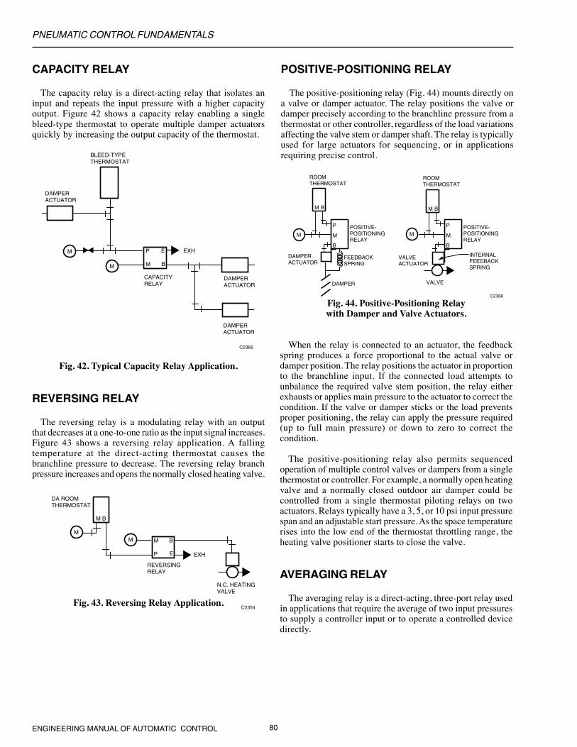
PNEUMATIC CONTROL FUNDAMENTALS
ENGINEERING MANUAL OF AUTOMATIC CONTROL 80
C2354
REVERSINGRELAY
DA ROOMTHERMOSTAT
M B
N.C. HEATINGVALVE
EXHP
M
E
BMM
CAPACITY RELAY
The capacity relay is a direct-acting relay that isolates aninput and repeats the input pressure with a higher capacityoutput. Figure 42 shows a capacity relay enabling a singlebleed-type thermostat to operate multiple damper actuatorsquickly by increasing the output capacity of the thermostat.
C2366
ROOMTHERMOSTAT
M B
B
M
P POSITIVE-POSITIONINGRELAY
INTERNALFEEDBACKSPRING
VALVE
VALVEACTUATOR
ROOMTHERMOSTAT
DAMPERACTUATOR
DAMPER
B
M
P POSITIVE-POSITIONINGRELAY
FEEDBACKSPRING
M B
M M
Fig. 42. Typical Capacity Relay Application.
REVERSING RELAY
The reversing relay is a modulating relay with an outputthat decreases at a one-to-one ratio as the input signal increases.Figure 43 shows a reversing relay application. A fallingtemperature at the direct-acting thermostat causes thebranchline pressure to decrease. The reversing relay branchpressure increases and opens the normally closed heating valve.
POSITIVE-POSITIONING RELAY
The positive-positioning relay (Fig. 44) mounts directly ona valve or damper actuator. The relay positions the valve ordamper precisely according to the branchline pressure from athermostat or other controller, regardless of the load variationsaffecting the valve stem or damper shaft. The relay is typicallyused for large actuators for sequencing, or in applicationsrequiring precise control.
Fig. 44. Positive-Positioning Relaywith Damper and Valve Actuators.
When the relay is connected to an actuator, the feedbackspring produces a force proportional to the actual valve ordamper position. The relay positions the actuator in proportionto the branchline input. If the connected load attempts tounbalance the required valve stem position, the relay eitherexhausts or applies main pressure to the actuator to correct thecondition. If the valve or damper sticks or the load preventsproper positioning, the relay can apply the pressure required(up to full main pressure) or down to zero to correct thecondition.
The positive-positioning relay also permits sequencedoperation of multiple control valves or dampers from a singlethermostat or controller. For example, a normally open heatingvalve and a normally closed outdoor air damper could becontrolled from a single thermostat piloting relays on twoactuators. Relays typically have a 3, 5, or 10 psi input pressurespan and an adjustable start pressure. As the space temperaturerises into the low end of the thermostat throttling range, theheating valve positioner starts to close the valve.
AVERAGING RELAY
The averaging relay is a direct-acting, three-port relay usedin applications that require the average of two input pressuresto supply a controller input or to operate a controlled devicedirectly.
Fig. 43. Reversing Relay Application.
BLEED-TYPETHERMOSTAT
DAMPERACTUATOR
CAPACITYRELAY
C2365
DAMPERACTUATOR
DAMPERACTUATOR
M
P
B
E EXHM
M

PNEUMATIC CONTROL FUNDAMENTALS
81 ENGINEERING MANUAL OF AUTOMATIC CONTROL
Figure 45 shows an averaging relay in a typical applicationwith two thermostat signals as inputs. The average of thethermostat signals controls a valve or damper actuator.
Fig. 45. Averaging Relay Application.
RATIO RELAY
The ratio relay is a four-port, non bleed relay that producesa modulating pressure output proportional to the thermostator controller branchline output. Ratio relays can be used tocontrol two or three pneumatic valves or damper actuators insequence from a single thermostat. The ratio relay has a fixedinput pressure range of either 3 or 5 psi for a 10 psi outputrange and an adjustable start point. For example, in a ratiorelay with a 5 psi range set for a 7 psi start, as the input pressurevaries from 7 to 12 psi (start point plus range), the outputpressure will vary from 3 to 13 psi.
In Figure 46, three 3 psi span ratio relays are set for 3 to 6,6 to 9, and 9 to 12 psi inputs, respectively. The thermostatsignal through the relays proportions in sequence the threevalves or actuators that have identical 3 to 13 psi springs.
PNEUMATIC POTENTIOMETER
The pneumatic potentiometer is a three-port, adjustablelinear restrictor used in control systems to sum two input signalvalues, average two input pressures, or as an adjustable flowrestriction. The potentiometer is a linear, restricted air passagebetween two input ports. The pressure at the adjustable outputport is a value based on the inputs at the two end connectionsand the location of the wiper between them.
Figure 47 shows a pneumatic potentiometer providing anaverage of two input signals. The wiper is set at mid-scale foraveraging or off-center for a weighted average. It can be usedthis way to average two air velocity transmitter signals fromducts with different areas by positioning the wiper accordingto the ratio of the duct areas. This outputs a signal proportionalto the airflow.
SIGNALS FROMSENSORS
WEIGHTEDAVERAGESIGNAL
AVERAGESIGNAL
C2374
PNEUMATIC POTENTIOMETER
INP
UT
1
OU
TP
UT
INP
UT
2
Fig. 47. Pneumatic Potentiometer as Averaging Relay.
Figure 48 shows a pneumatic potentiometer as an adjustableairflow restrictor.
Fig. 48. Pneumatic Potentiometer as
THERMOSTAT 2THERMOSTAT 1
AVERAGINGRELAY
C2345
M B M B
P2B
P1
TOACTUATOR
M
Fig. 46. Ratio Relays in Sequencing Control Application.
Adjustable Airflow Restrictor.
TO CONTROLLEDDEVICE
C2372
PNEUMATIC POTENTIOMETER
INP
UT
1
OU
TP
UT
INP
UT
2
M CAP
C2370
RATIO RELAY 13-6 PSI
HEATINGVALVE3–13 PSI
MIXINGDAMPERS3–13 PSI
COOLINGVALVE3–13 PSI
DA ZONETHERMOSTAT
M BEXH
M
RATIO RELAY 39-12 PSI
EXH
M
M
M
E
B
P
RATIO RELAY 26-9 PSI
EXH
M M
E
B
P
M
E
B
P

PNEUMATIC CONTROL FUNDAMENTALS
ENGINEERING MANUAL OF AUTOMATIC CONTROL 82
18
16
14
12
10
8
6
4
2
0
RE
LAY
OU
TP
UT
(P
SI)
RELAY INPUT (PSI)
KNOB SETTING (%)
100806040200
0 2 4 6 8 10 12 14 16 18C1097
7
HESITATION RELAY
The hesitation relay is used with a pneumatic actuator inunit ventilator applications. The output pressure goes tominimum whenever the input pressure is below the minimumsetting. Figure 49 shows a graph of the output of a hesitationrelay as controlled by the relay knob settings (piloted from thethermostat).
M
M B
M
P
B M
DA ROOMTHERMOSTAT
HESITATIONRELAY
DAMPERACTUATOR
C2346
Fig. 49. Hesitation Relay Output Pressureas a Function of Knob Setting.
The hesitation relay has an internal restrictor. Figure 50shows a typical application of a hesitation relay and apneumatic damper actuator. When the thermostat branchlinepressure reaches 1.5 psi, the relay output goes to its presetminimum pressure. When the branchline pressure of thethermostat reaches the setting of the hesitation relay, thethermostat controls the damper actuator. When the thermostatbranchline pressure drops below the hesitation relay setting,the relay holds the damper actuator at the minimum positionuntil the thermostat branchline pressure drops below 1.5 psi.At that point, the hesitation relay output falls to zero.
ELECTRICAL INTERLOCKING RELAYS
Electrical interlocking relays bridge electric and pneumaticcircuits. The electric-pneumatic relay uses electric power toactuate an air valve in an associated pneumatic circuit. Thepneumatic-electric relay uses control air pressure to make orbreak an associated electrical circuit.
ELECTRIC-PNEUMATIC RELAY
The electric-pneumatic (E/P) relay is a two-position, three-way air valve. Depending on the piping connections to theports, the relay performs the same functions as a simplediverting relay. A common application for the E/P relay is toexhaust and close an outdoor air damper in a fan system whenthe fan motor is turned off, as shown in Figure 51.
M
FAN INTERLOCKVOLTAGE
EXH
O X C
OUTDOORAIR DAMPERACTUATOR
PLUNGER
RELAY COIL
SOLENOIDSPRING
E/P RELAY
C2602
Fig. 51. E/P Relay Application.
When the relay coil is de-energized, the solenoid spring seatsthe plunger. The normally disconnected port (X) is blockedand the normally connected port (O) connects to the commonport (C). The connection exhausts the damper actuator whichcloses the damper. When the relay coil is energized, the plungerlifts against the tension of the spring and blocks the normallyconnected port (O). Main air at the normally disconnected port(X) connects to the common port (C) and opens the damper.
PNEUMATIC-ELECTRIC RELAY
Figure 52 shows a simplified pneumatic-electric (P/E) relaywith a spdt switch. The P/E relay makes the normally closedcontact on a fall in pilot pressure below the setpoint, and makesthe normally open contact on a rise above a value equal to thesetpoint plus the differential. For example, with a setpointadjustment of 3 psi and a differential of 2 psi, the pump isenergized at pilot pressures below 3 psi and turns off at pilotpressures above 5 psi.
Fig. 50. Typical Hesitation Relay Application.

PNEUMATIC CONTROL FUNDAMENTALS
83 ENGINEERING MANUAL OF AUTOMATIC CONTROL
M
M B
P/E RELAY
TEMPERATURECONTROLLER
BELLOWS
SPRING
SETPOINTADJUSTMENT
PUMP
PUMPVOLTAGE
N.O.
N.C.
C
C2384
Fig. 52. P/E Relay Application.
ELECTRONIC-PNEUMATIC TRANSDUCER
The electronic-pneumatic transducer is a proportional relaythat varies the branch air pressure linearly 3 to 15 psi inresponse to changes in an electrical input of 2 to 10 volts or 4to 20 ma. Electronic-pneumatic transducers are used as theinterface between electronic, digital, or computer-based controlsystems and pneumatic output devices (e.g., actuators).
Figure 53 shows discharge air temperature control of aheating coil using digital control for sensing and control. Theoutput of the transducer positions the valve on a heating coil.
M B
M
HEATINGVALVE
DISCHARGEAIR
HEATING COIL
ELECTRONIC-PNEUMATICTRANSDUCER
DDCCONTROLLER
ELECTRONICTEMPERATURESENSOR
C2378
A resistance-type temperature sensor in the discharge airduct is the input to the controller, which provides all of thesystem adjustments and logic requirements for control. Thecontroller output of 2 to 10 volts dc is input to the electronic-pneumatic transducer, which converts the signal to a 3 to 15psi output to position the heating valve.
PNEUMATIC SWITCH
The pneumatic switch is available in two- or three-positionmodels (Fig. 54). Rotating the switch knob causes the ports toalign in one of two ways in a two-position switch, and in oneof three ways in a three-position switch. The two-positionswitch is used for circuit interchange. The three-position switchsequentially switches the common port (Port 2) to the otherports and blocks the disconnected ports.
Fig. 53. Typical Electronic-PneumaticTransducer Application.
1
2
3
4
1
2
3
4
1
2
3
4
1
2
3
4
1
2
3
4
THREE-POSITION SWITCH
TWO-POSITION SWITCH
C1887
Fig. 54. Pneumatic Switches.
Figure 55 shows a typical application for sequentialswitching. In the OPEN position, the valve actuator exhauststhrough Port 4 and the valve opens. In the AUTO position, theactuator connects to the thermostat and the valve is in theautomatic mode. In the CLOSED position, the actuatorconnects to main air and the valve closes.

PNEUMATIC CONTROL FUNDAMENTALS
ENGINEERING MANUAL OF AUTOMATIC CONTROL 84
Fig. 55. Typical OPEN/AUTO/CLOSED Application.
MANUAL POSITIONING SWITCH
A manual positioning switch is used to position a remotevalve or damper or change the setpoint of a controller. Theswitch takes input air from a controller and passes a preset,constant, minimum air pressure to the branch regardless ofthe controller output (e.g., to provide an adjustable minimumposition of an outdoor air damper). Branchline pressure fromthe controller to other devices connected to the controller isnot affected.
Figure 56 shows the switch functioning as a minimumpositioning switch. The damper will not close beyond theminimum setting of the positioning switch. As the controllersignal increases above the switch setting, the switch positionsthe damper according to the controller signal.
M
M B
DATHERMOSTAT
TO OTHERVALVES
N.O. HEATING COIL VALVES
C2349
PNEUMATIC CONTROL COMBINATIONS
Fig. 56. Typical Three-Port MinimumPosition Switch Application.
Manual switches are generally panel mounted with a dialplate or nameplate on the front of the panel which shows theswitch position. Gages are sometimes furnished to indicatethe main and branch pressures to the switch.
GENERAL
A complete control system requires combinations of severalcontrols. Figure 57 shows a basic control combination of athermostat and one or more control valves. A normally opencontrol valve assembly is selected when the valve must openif the air supply fails. A normally open control valve requiresa direct-acting thermostat in the heating application shown inFigure 56. Cooling applications may use normally closedvalves and a direct-acting thermostat. The thermostat in Figure56 has a 5 degree throttling range (output varies from 3 to 13psi of the 5 degree range) and the valves have an 8 to 12 psispring range, then the valve will modulate from open to closedon a 2 degree rise in temperature at the thermostat.
X 5F° = 2F°
Fig. 57. Thermostat and One orMore Normally Open Valves.
A normally open or a normally closed valve may becombined with a direct-acting or a reverse-acting thermostat,depending on the requirements and the conditions in thecontrolled space. Applications that require several valvescontrolled in unison (e.g., multiple hot water radiation unitsin a large open area) have two constraints:
— All valves that perform the same function must be ofthe same normal position (all normally open or allnormally closed).
NOTE: POSITION 1: OPEN—PORTS 2 AND 4 CONNECTED POSITION 2: AUTO—PORTS 2 AND 3 CONNECTED
POSITION 3: CLOSED—PORTS 2 AND 1 CONNECTED
M10295
N.O. VALVE
EXH
DA THERMOSTATM B
1
2
3
4
M
M
THREE-POSITIONSWITCH
4 psi10 psi
M
M B
M
B
P M
OA DAMPERACTUATOR
MINIMUMPOSITIONSWITCH
DA MIXED AIRTEMPERATURECONTROLLER
VALVE
C2348
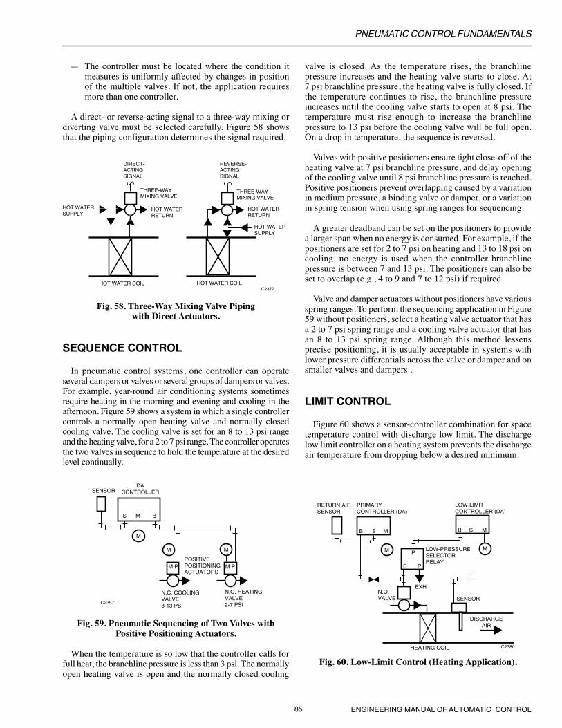
PNEUMATIC CONTROL FUNDAMENTALS
85 ENGINEERING MANUAL OF AUTOMATIC CONTROL
— The controller must be located where the condition itmeasures is uniformly affected by changes in positionof the multiple valves. If not, the application requiresmore than one controller.
A direct- or reverse-acting signal to a three-way mixing ordiverting valve must be selected carefully. Figure 58 showsthat the piping configuration determines the signal required.
M M
M
S M B
M P M PPOSITIVEPOSITIONINGACTUATORS
N.C. COOLINGVALVE8-13 PSI
N.O. HEATINGVALVE2-7 PSI
SENSORDA
CONTROLLER
C2357
valve is closed. As the temperature rises, the branchlinepressure increases and the heating valve starts to close. At7 psi branchline pressure, the heating valve is fully closed. Ifthe temperature continues to rise, the branchline pressureincreases until the cooling valve starts to open at 8 psi. Thetemperature must rise enough to increase the branchlinepressure to 13 psi before the cooling valve will be full open.On a drop in temperature, the sequence is reversed.
Valves with positive positioners ensure tight close-off of theheating valve at 7 psi branchline pressure, and delay openingof the cooling valve until 8 psi branchline pressure is reached.Positive positioners prevent overlapping caused by a variationin medium pressure, a binding valve or damper, or a variationin spring tension when using spring ranges for sequencing.
A greater deadband can be set on the positioners to providea larger span when no energy is consumed. For example, if thepositioners are set for 2 to 7 psi on heating and 13 to 18 psi oncooling, no energy is used when the controller branchlinepressure is between 7 and 13 psi. The positioners can also beset to overlap (e.g., 4 to 9 and 7 to 12 psi) if required.
Valve and damper actuators without positioners have variousspring ranges. To perform the sequencing application in Figure59 without positioners, select a heating valve actuator that hasa 2 to 7 psi spring range and a cooling valve actuator that hasan 8 to 13 psi spring range. Although this method lessensprecise positioning, it is usually acceptable in systems withlower pressure differentials across the valve or damper and onsmaller valves and dampers .
LIMIT CONTROL
Figure 60 shows a sensor-controller combination for spacetemperature control with discharge low limit. The dischargelow limit controller on a heating system prevents the dischargeair temperature from dropping below a desired minimum.
Fig. 59. Pneumatic Sequencing of Two Valves withPositive Positioning Actuators.
When the temperature is so low that the controller calls forfull heat, the branchline pressure is less than 3 psi. The normallyopen heating valve is open and the normally closed cooling
HOT WATERSUPPLY
HOT WATERSUPPLY
DIRECT-ACTINGSIGNAL
THREE-WAYMIXING VALVE
HOT WATERRETURN
HOT WATERRETURN
THREE-WAYMIXING VALVE
REVERSE-ACTINGSIGNAL
C2377HOT WATER COIL HOT WATER COIL
Fig. 58. Three-Way Mixing Valve Pipingwith Direct Actuators.
SEQUENCE CONTROL
In pneumatic control systems, one controller can operateseveral dampers or valves or several groups of dampers or valves.For example, year-round air conditioning systems sometimesrequire heating in the morning and evening and cooling in theafternoon. Figure 59 shows a system in which a single controllercontrols a normally open heating valve and normally closedcooling valve. The cooling valve is set for an 8 to 13 psi rangeand the heating valve, for a 2 to 7 psi range. The controller operatesthe two valves in sequence to hold the temperature at the desiredlevel continually.
N.O.VALVE
HEATING COIL C2380
DISCHARGEAIR
B S M
M
B P
P
B S M
M
SENSOR
RETURN AIRSENSOR
PRIMARYCONTROLLER (DA)
LOW-LIMITCONTROLLER (DA)
LOW-PRESSURESELECTORRELAY
EXH
Fig. 60. Low-Limit Control (Heating Application).
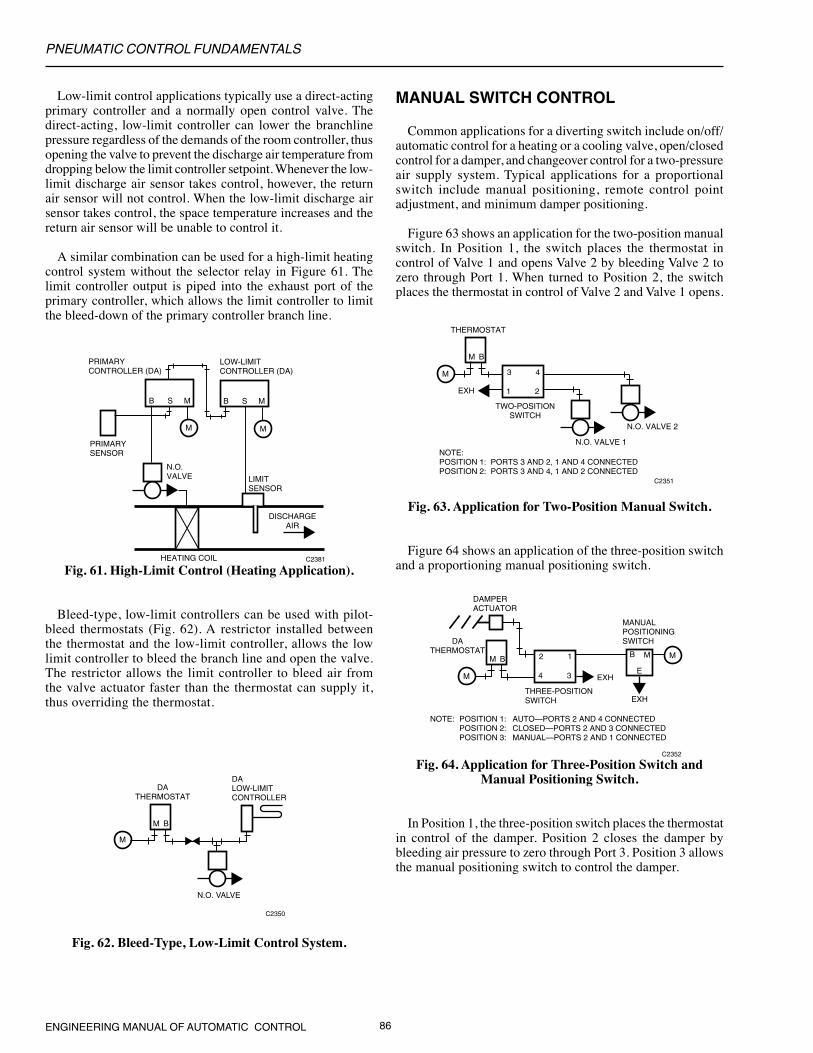
PNEUMATIC CONTROL FUNDAMENTALS
ENGINEERING MANUAL OF AUTOMATIC CONTROL 86
Low-limit control applications typically use a direct-actingprimary controller and a normally open control valve. Thedirect-acting, low-limit controller can lower the branchlinepressure regardless of the demands of the room controller, thusopening the valve to prevent the discharge air temperature fromdropping below the limit controller setpoint. Whenever the low-limit discharge air sensor takes control, however, the returnair sensor will not control. When the low-limit discharge airsensor takes control, the space temperature increases and thereturn air sensor will be unable to control it.
A similar combination can be used for a high-limit heatingcontrol system without the selector relay in Figure 61. Thelimit controller output is piped into the exhaust port of theprimary controller, which allows the limit controller to limitthe bleed-down of the primary controller branch line.
C2381
B S M
DISCHARGEAIR
LIMITSENSOR
B S M
M
PRIMARYCONTROLLER (DA)
LOW-LIMITCONTROLLER (DA)
N.O.VALVE
HEATING COIL
M
B S M
PRIMARYSENSOR
Fig. 61. High-Limit Control (Heating Application).
Bleed-type, low-limit controllers can be used with pilot-bleed thermostats (Fig. 62). A restrictor installed betweenthe thermostat and the low-limit controller, allows the lowlimit controller to bleed the branch line and open the valve.The restrictor allows the limit controller to bleed air fromthe valve actuator faster than the thermostat can supply it,thus overriding the thermostat.
M
M B
DATHERMOSTAT
N.O. VALVE
C2350
DALOW-LIMITCONTROLLER
MANUAL SWITCH CONTROL
Common applications for a diverting switch include on/off/automatic control for a heating or a cooling valve, open/closedcontrol for a damper, and changeover control for a two-pressureair supply system. Typical applications for a proportionalswitch include manual positioning, remote control pointadjustment, and minimum damper positioning.
Figure 63 shows an application for the two-position manualswitch. In Position 1, the switch places the thermostat incontrol of Valve 1 and opens Valve 2 by bleeding Valve 2 tozero through Port 1. When turned to Position 2, the switchplaces the thermostat in control of Valve 2 and Valve 1 opens.
M
M B
THERMOSTAT
C2351
3
1
4
2EXH
TWO-POSITIONSWITCH
N.O. VALVE 1
N.O. VALVE 2
NOTE:POSITION 1: PORTS 3 AND 2, 1 AND 4 CONNECTEDPOSITION 2: PORTS 3 AND 4, 1 AND 2 CONNECTED
M
M B
DATHERMOSTAT
C2352
THREE-POSITIONSWITCH
NOTE: POSITION 1: AUTO—PORTS 2 AND 4 CONNECTED POSITION 2: CLOSED—PORTS 2 AND 3 CONNECTED
POSITION 3: MANUAL—PORTS 2 AND 1 CONNECTED
DAMPERACTUATOR
M2
4
1
3 EXH
B
E
M
EXH
MANUALPOSITIONINGSWITCH
Fig. 62. Bleed-Type, Low-Limit Control System.
Fig. 63. Application for Two-Position Manual Switch.
Figure 64 shows an application of the three-position switchand a proportioning manual positioning switch.
Fig. 64. Application for Three-Position Switch andManual Positioning Switch.
In Position 1, the three-position switch places the thermostatin control of the damper. Position 2 closes the damper bybleeding air pressure to zero through Port 3. Position 3 allowsthe manual positioning switch to control the damper.
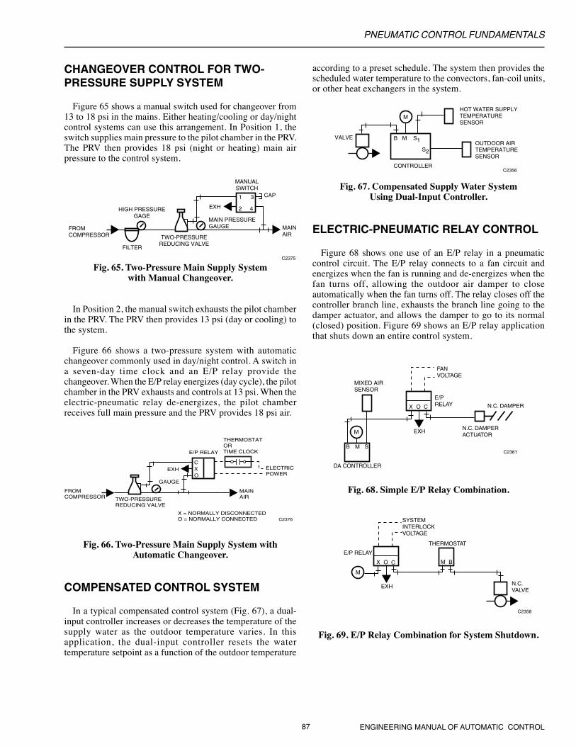
PNEUMATIC CONTROL FUNDAMENTALS
87 ENGINEERING MANUAL OF AUTOMATIC CONTROL
1 3
2 4
CAP
HIGH PRESSUREGAGE
FROMCOMPRESSOR
FILTER
TWO-PRESSUREREDUCING VALVE
EXH
MANUALSWITCH
MAIN PRESSUREGAUGE MAIN
AIR
C2375
CHANGEOVER CONTROL FOR TWO-PRESSURE SUPPLY SYSTEM
Figure 65 shows a manual switch used for changeover from13 to 18 psi in the mains. Either heating/cooling or day/nightcontrol systems can use this arrangement. In Position 1, theswitch supplies main pressure to the pilot chamber in the PRV.The PRV then provides 18 psi (night or heating) main airpressure to the control system.
FROMCOMPRESSOR TWO-PRESSURE
REDUCING VALVE
X = NORMALLY DISCONNECTEDO = NORMALLY CONNECTED
EXH
MAINAIR
C2376
C
OX ELECTRIC
POWER
THERMOSTATORTIME CLOCKE/P RELAY
GAUGE
Fig. 65. Two-Pressure Main Supply Systemwith Manual Changeover.
In Position 2, the manual switch exhausts the pilot chamberin the PRV. The PRV then provides 13 psi (day or cooling) tothe system.
Figure 66 shows a two-pressure system with automaticchangeover commonly used in day/night control. A switch ina seven-day time clock and an E/P relay provide thechangeover. When the E/P relay energizes (day cycle), the pilotchamber in the PRV exhausts and controls at 13 psi. When theelectric-pneumatic relay de-energizes, the pilot chamberreceives full main pressure and the PRV provides 18 psi air.
according to a preset schedule. The system then provides thescheduled water temperature to the convectors, fan-coil units,or other heat exchangers in the system.
Fig. 67. Compensated Supply Water SystemUsing Dual-Input Controller.
ELECTRIC-PNEUMATIC RELAY CONTROL
Figure 68 shows one use of an E/P relay in a pneumaticcontrol circuit. The E/P relay connects to a fan circuit andenergizes when the fan is running and de-energizes when thefan turns off, allowing the outdoor air damper to closeautomatically when the fan turns off. The relay closes off thecontroller branch line, exhausts the branch line going to thedamper actuator, and allows the damper to go to its normal(closed) position. Figure 69 shows an E/P relay applicationthat shuts down an entire control system.
Fig. 66. Two-Pressure Main Supply System withAutomatic Changeover.
COMPENSATED CONTROL SYSTEM
In a typical compensated control system (Fig. 67), a dual-input controller increases or decreases the temperature of thesupply water as the outdoor temperature varies. In thisapplication, the dual-input controller resets the watertemperature setpoint as a function of the outdoor temperature
EXHM
X O C
MIXED AIR SENSOR
B M S
FANVOLTAGE
E/PRELAY
N.C. DAMPERACTUATOR
N.C. DAMPER
C2361
DA CONTROLLER
C2358
EXH N.C.VALVE
THERMOSTAT
M B
M
X O C
SYSTEMINTERLOCKVOLTAGE
E/P RELAY
Fig. 68. Simple E/P Relay Combination.
Fig. 69. E/P Relay Combination for System Shutdown.
M
VALVE
HOT WATER SUPPLYTEMPERATURESENSOR
OUTDOOR AIRTEMPERATURESENSOR
CONTROLLER
B M S1
S2
C2356

PNEUMATIC CONTROL FUNDAMENTALS
ENGINEERING MANUAL OF AUTOMATIC CONTROL 88
THERMOSTAT
M B
M
C N.C. N.O.
WIRED TOSTART FAN 1
P/E RELAYS
SET5-7 PSI
SET10-12 PSI
C N.C. N.O.
WIRED TOSTART FAN 2
C2359
PNEUMATIC-ELECTRIC RELAY CONTROL
A P/E relay provides the interlock when a pneumaticcontroller actuates electric equipment. The relays can be setfor any desired pressure. Figure 70 shows two P/E relayssequenced to start two fans, one at a time, as the fans are needed.
branchline pressure to 14 psi, Relay 2 breaks the normallyclosed circuit and makes the normally open circuit, removingvoltage from Relay 1, shutting down the low speed, andenergizing the high speed. On a decrease in temperature, thesequence reverses and the changes occur at 12 and 7 psirespectively.
PNEUMATIC RECYCLING CONTROL
E/P and P/E relays can combine to perform a variety of logicfunctions. On a circuit with multiple electrically operateddevices, recycling control can start the devices in sequence toprevent the circuit from being overloaded. If power fails,recycling the system from its starting point prevents the circuitoverload that could occur if all electric equipment restartssimultaneously when power resumes.
Figure 72 shows a pneumatic-electric system that recyclesequipment when power fails.
EXH
X O C
E/PRELAY
CHECKVALVE
P/ERELAYS
M
M B
THERMOSTAT
C2368
TO LOAD SIDEOF POWER
SUPPLY SWITCHWIRED TO START
ELECTRICAL EQUIPMENT
H G
ADJUSTABLERESTRICTOR
Fig. 70. P/E Relays Controlling Fans in Sequence.
On a rise in temperature, Relay 1 puts Fan 1 in operation asthe thermostat branchline pressure reaches 7 psi. Relay 2 startsFan 2 when the controller branchline pressure reaches 12 psi.On a decrease in branchline pressure, Relay 2 stops Fan 2 at10 psi branchline pressure, and Relay 1 stops Fan 1 at 5 psibranchline pressure.
Figure 71 shows two spdt P/E relays starting and stopping atwo-speed fan to control condenser water temperature.
Fig. 71. Two-Speed Fan Operated by P/E Relays.
Voltage is applied to the common contact of Relay 1 fromthe normally closed contact of Relay 2. When the controllerbranchline pressure rises to 9 psi, the cooling tower fan isstarted on low speed by Relay 1 which makes common tonormally open. As a further rise in temperature increases the
Fig. 72. Recycling System for Power Failure.
When power is applied, the E/P relay operates to close theexhaust and connect the thermostat through an adjustablerestrictor to the P/E relays. The electrical equipment starts insequence determined by the P/E relay settings, the adjustablerestrictor, and the branchline pressure from the thermostat. Theadjustable restrictor provides a gradual buildup of branchlinepressure to the P/E relays for an adjustable delay betweenstartups. On power failure, the E/P relay cuts off the thermostatbranch line to the two P/E relays and bleeds them off throughits exhaust port, shutting down the electrical equipment. Thecheck valve allows the thermostat to shed the controlled loadsas rapidly as needed (without the delay imposed by therestrictor).
M
B M S
C N.C. N.O.
DACONTROLLER
P/E RELAY 2SET 12-14 PSI
C N.C. N.O.
COOLING TOWERFAN STARTERCONTROL VOLTAGE
OVERLOAD
LOW SPEED
HIGH AUXILIARY LOW AUXILIARY
HIGH SPEED
FAN STARTER
P/E RELAY 1SET 7-9 PSI
SENSOR INCONDENSERWATER
C2367

PNEUMATIC CONTROL FUNDAMENTALS
89 ENGINEERING MANUAL OF AUTOMATIC CONTROL
The Discharge Air Temperature Indicator is fed from thepneumatic discharge air temperature sensor and the Three-WayValve Gauge is fed from the valve control line.
When pneumatic automation panels are located local to theHVAC system, they are usually connected with 1/4 inch plastictubing. When there are many lines at extended lengths, smallerdiameter plastic tubing may be preferable to save space andmaintain responsiveness. When the panel devices are remote,the air supply should be sourced remotely to avoid pressurelosses due to long flow lines. The switching air may be fromthe automation panel or it may be fed via a remote restrictorand piped in an exhaust configuration.
0
10 2030
100
9080
70
605040
3020
100
PSI DISCHARGE AIRTEMPERATURE
OPENON
RETURNAIR
SUPPLYFAN
OUTSIDEAIR
AHU 6
ON OFF
COOLINGCOIL
M10297
4-11 PSINORMALLYOPEN
PNEUMATIC CENTRALIZATION
Building environmental systems may be pneumaticallyautomated to any degree desired. Figure 73 provides anexample of the front of a pneumatic automation panel. Thispanel contains pneumatic controls and may be local to thecontrolled HVAC system, or it may be located centrally in amore convenient location.
In this example, the on-off toggle switch starts and stops thefan. The toggle switch may be electric, or pneumatic with aPneumatic-Electric (P/E) relay.
Two pneumatic “target” gauges are shown for the outsideair damper and the supply fan. The ON/OFF Supply Fan Gaugeis fed from a fan proof-of-flow relay, and the OPEN/CLOSEDDamper Gauge is fed from the damper control line.
Fig. 73. Pneumatic Centralization
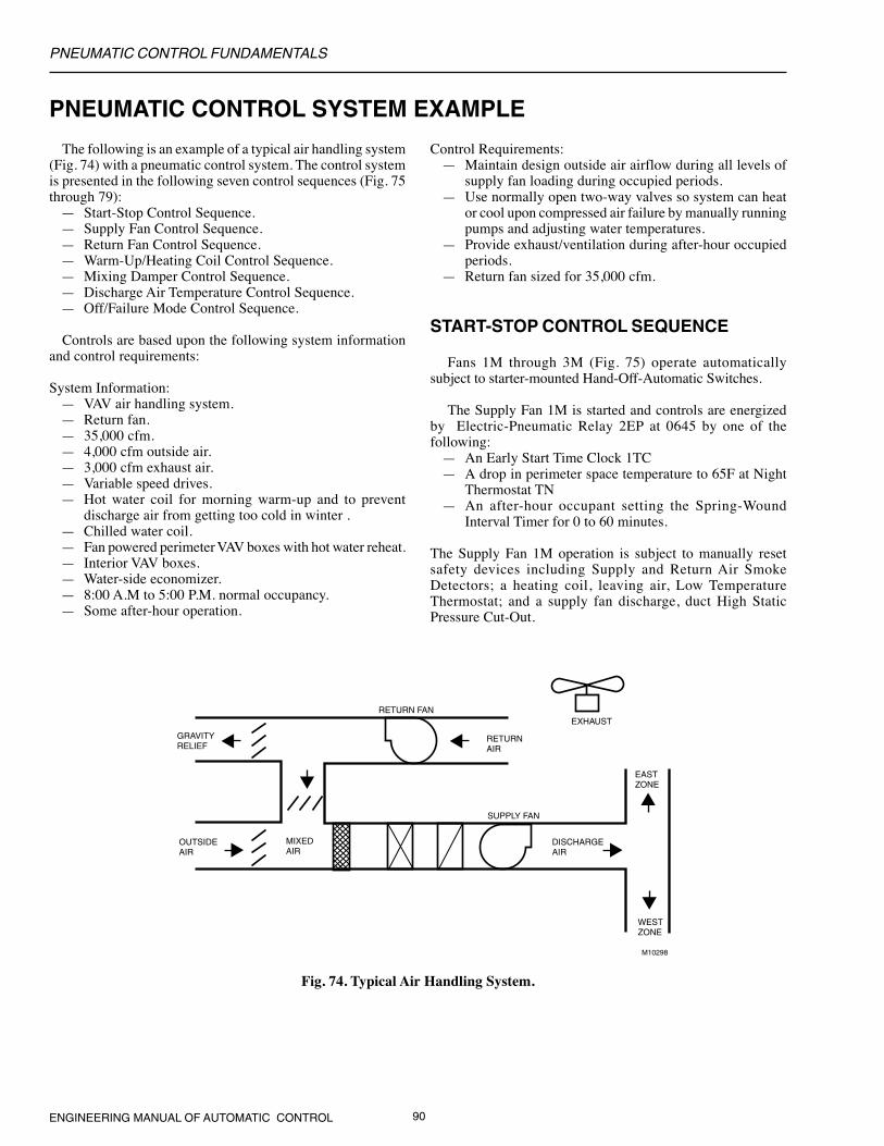
PNEUMATIC CONTROL FUNDAMENTALS
ENGINEERING MANUAL OF AUTOMATIC CONTROL 90
PNEUMATIC CONTROL SYSTEM EXAMPLE
The following is an example of a typical air handling system(Fig. 74) with a pneumatic control system. The control systemis presented in the following seven control sequences (Fig. 75through 79):
— Start-Stop Control Sequence.— Supply Fan Control Sequence.— Return Fan Control Sequence.— Warm-Up/Heating Coil Control Sequence.— Mixing Damper Control Sequence.— Discharge Air Temperature Control Sequence.— Off/Failure Mode Control Sequence.
Controls are based upon the following system informationand control requirements:
System Information:— VAV air handling system.— Return fan.— 35,000 cfm.— 4,000 cfm outside air.— 3,000 cfm exhaust air.— Variable speed drives.— Hot water coil for morning warm-up and to prevent
discharge air from getting too cold in winter .— Chilled water coil.— Fan powered perimeter VAV boxes with hot water reheat.— Interior VAV boxes.— Water-side economizer.— 8:00 A.M to 5:00 P.M. normal occupancy.— Some after-hour operation.
GRAVITYRELIEF
RETURNAIR
RETURN FAN
SUPPLY FAN
EASTZONE
DISCHARGEAIR
WESTZONE
MIXED AIR
OUTSIDEAIR
EXHAUST
M10298
Control Requirements:— Maintain design outside air airflow during all levels of
supply fan loading during occupied periods.— Use normally open two-way valves so system can heat
or cool upon compressed air failure by manually runningpumps and adjusting water temperatures.
— Provide exhaust/ventilation during after-hour occupiedperiods.
— Return fan sized for 35,000 cfm.
START-STOP CONTROL SEQUENCE
Fans 1M through 3M (Fig. 75) operate automaticallysubject to starter-mounted Hand-Off-Automatic Switches.
The Supply Fan 1M is started and controls are energizedby Electric-Pneumatic Relay 2EP at 0645 by one of thefollowing:
— An Early Start Time Clock 1TC— A drop in perimeter space temperature to 65F at Night
Thermostat TN— An after-hour occupant setting the Spring-Wound
Interval Timer for 0 to 60 minutes.
The Supply Fan 1M operation is subject to manually resetsafety devices including Supply and Return Air SmokeDetectors; a heating coil, leaving air, Low TemperatureThermostat; and a supply fan discharge, duct High StaticPressure Cut-Out.
Fig. 74. Typical Air Handling System.

PNEUMATIC CONTROL FUNDAMENTALS
91 ENGINEERING MANUAL OF AUTOMATIC CONTROL
Any time the Supply Fan 1M runs, the Return Fan 2M runs.
Any time the Return Fan 2M runs, the Exhaust Fan 3Mand the ventilation controls are energized by the After-Hours
Fig. 75. Start-Stop Control.
3MEXHAUST
FAN
480V
X1-3X2-3
2MEXHAUST
FAN
480V
X1-2X2-2
1MEXHAUST
FAN
480V
X1-1X2-1
TN
1TC
1CR
NIGHT'STAT
2EP
1EP
1M
1M
OL
SMOKEDETECTOR
SUPPLY RETURN
LOW TEMPERATURETHERMOSTAT
HIGH STATICPRESSURECUTOUT
X1-1 X2-1
1M2M
2M
OL
X1-2 X2-2
A
H
A
H
2CR
2CR
2M
1CR
2TC
3M
3M
OL
X1-3 X2-3
A
H
H
FIREEXHAUST
1CR
2TC
1TC
TIME CLOCKS
INTERVAL TIMER(AFTER HOURS)
N
120 VOLT CONTROL CIRCUIT
M10303
2CR
EARLY START CLOCK
OCCUPANCY CLOCK
Interval Timer or by the Occupancy Schedule Time Clock2TC set for 0750.
Both Clocks 1TC and 2TC are set to shut the system downat 1700.

PNEUMATIC CONTROL FUNDAMENTALS
ENGINEERING MANUAL OF AUTOMATIC CONTROL 92
SUPPLY FAN CONTROL SEQUENCE
Any time the Supply Fan (Fig. 76) runs, the pressurecontroller with the greatest demand, Static Pressure ControllerPC
1 or PC
2, operates the Electronic-Pressure Transducer PT.
The controller used is determined by High Pressure SelectorRelay HSR. Transducer PT controls the Supply Fan VariableSpeed Drive (VSD) to maintain duct static pressure. The pick-up probes for Static Pressure Controllers PC
1 and PC
2 are
located at the end of the east and west zone ducts.
VSD
L
B
RA1.5 IN. WC
RA1.5 IN. WC
PC2
PC1M
2EP
H
BP2
P1
L
B M
H
PT
SUPPLY FAN
M10300
STARTER
EAST ZONE
WEST ZONE
HSR
VSDREFERENCE PICK-UPRUN TO 15 FEETABOVE ROOF
L
B
DA0.05 IN. WC
PCM
2EP
H
1PT
TO SPACESTATIC PRESSUREPICK-UP
RETURN FAN
M10299
STARTER
Fig. 76. Supply Fan Load Control.
RETURN FAN CONTROL SEQUENCE
Static Pressure Controller PC (Fig. 77) controls the returnfan variable speed drive to maintain space static pressure. Thepick-up probe is located in the space
NOTE: 1. Because of varying exhaust between occupied andwarm-up modes, space static pressure control ofthe return fan is selected. Return fan tracking fromsupply fan airflow is acceptable but is complex ifvarying exhaust is worked into the control scheme.
2. Exercise care in selecting location of the insidepick-up and in selection of the pressure controller.Location of the reference pick-up above the roofis recommended by ASHRAE.
3. To prevent unnecessary hunting by the return fanat start-up, the supply fan control signal should beslow loading such that the supply fan goes fromzero or a minimum to maximum load over threeminutes. Shut down should not be restricted.
WARM-UP/HEATING COIL CONTROLSEQUENCE
Any time the Supply Fan (Fig. 78) runs and the return airtemperature is below 69F, Temperature Controller TC-1 tripsSnap-Acting Relay SA-1 to position Switching Relays SR-1and SR-2 to initialize warm-up control. Relay SA-1 alsopositions Switching Relay SR-4 to disable cooling controls.Switching Relay SR-2 opens all interior VAV box dampersand starts the hot water pump. Relay SR-1 switches the hotwater valve from normal control to warm-up control viaController TC-2 and modulates the hot water valve to maintaina discharge air temperature setpoint of 90F.
NOTE: Fan powered perimeter VAV boxes are cool in thismode and operate with the fans on and at the minimumairflow (warm air) setpoints. Reheat valves at eachbox operate as needed. This allows the warm-up cycleto operate the air handling unit (AHU) fans at areduced and low cost power range.
Fig. 77. Return Fan Load Control.
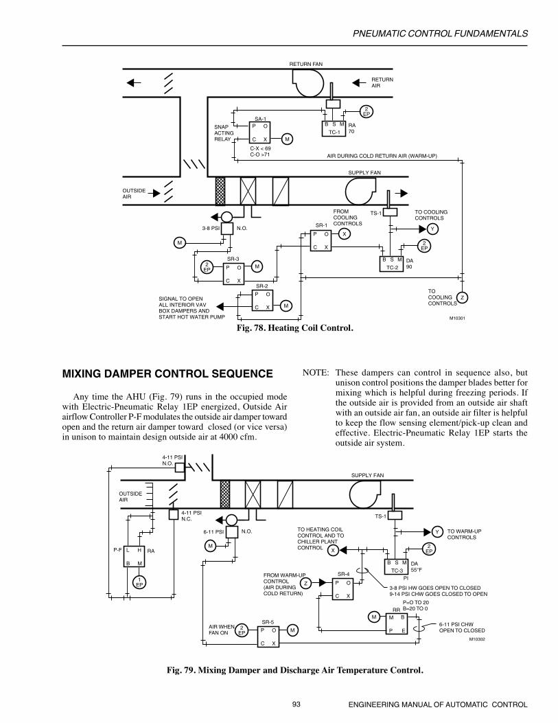
PNEUMATIC CONTROL FUNDAMENTALS
93 ENGINEERING MANUAL OF AUTOMATIC CONTROL
Fig. 78. Heating Coil Control.
M
M
Y
2EP
2EP
M
Z
X
P
C X
O
P
C X
O
M
P
C X
O
P
C X
O
SR-1
SR-3
SR-2
RA70
B S M
TC-1
2EP
DA90
B S M
TC-2
SA-1
C-X < 69C-O >71
SNAPACTINGRELAY
RETURNAIR
RETURN FAN
OUTSIDEAIR
TO COOLINGCONTROLS
TS-1FROMCOOLINGCONTROLS
3-8 PSI N.O.
SIGNAL TO OPENALL INTERIOR VAVBOX DAMPERS ANDSTART HOT WATER PUMP M10301
TOCOOLINGCONTROLS
SUPPLY FAN
AIR DURING COLD RETURN AIR (WARM-UP)
MIXING DAMPER CONTROL SEQUENCE
Any time the AHU (Fig. 79) runs in the occupied modewith Electric-Pneumatic Relay 1EP energized, Outside Airairflow Controller P-F modulates the outside air damper towardopen and the return air damper toward closed (or vice versa)in unison to maintain design outside air at 4000 cfm.
M
Y
Z
M
X
P
C X
O
SR-4
P
C X
O
SR-5
2EP
DA55°F
B S M
TC-3
L
B M
HP-F RA
OUTSIDEAIR
2EP
1EP
TO WARM-UPCONTROLS
TS-1
6-11 PSI N.O.
4-11 PSIN.O.
M M
P E
BRR
FROM WARM-UP CONTROL(AIR DURING COLD RETURN)
M10302
SUPPLY FAN
P=O TO 20B=20 TO 0
6-11 PSI CHWOPEN TO CLOSED
AIR WHENFAN ON
TO HEATING COILCONTROL AND TOCHILLER PLANTCONTROL
3-8 PSI HW GOES OPEN TO CLOSED9-14 PSI CHW GOES CLOSED TO OPEN
4-11 PSIN.C.
PI
NOTE: These dampers can control in sequence also, butunison control positions the damper blades better formixing which is helpful during freezing periods. Ifthe outside air is provided from an outside air shaftwith an outside air fan, an outside air filter is helpfulto keep the flow sensing element/pick-up clean andeffective. Electric-Pneumatic Relay 1EP starts theoutside air system.
Fig. 79. Mixing Damper and Discharge Air Temperature Control.
PNEUMATIC CONTROL FUNDAMENTALS
ENGINEERING MANUAL OF AUTOMATIC CONTROL 94
DISCHARGE AIR TEMPERATURECONTROL SEQUENCE
Any time the AHU (Fig. 79) operates in the non-warm-upmode, Switching Relay SR-4 operates to allow the normalDischarge Air Temperature Controller TC-3 to modulate thehot water valve closed (through Switching Relay SR-1, Fig. 77)and the chilled water valve open in sequence, on a risingcooling load, to maintain the Temperature Controller TC-3setpoint. Controller TC-3 is a PI (proportional plus integral)controller.
NOTE: In this constant 4000 cfm outside air system, if thereturn air is 72F and the outside air is -5F, the mixedair temperature will drop below 55F if the AHUairflow drops below 52 percent of the design airflow.
OFF/FAILURE MODE CONTROLSEQUENCE
If compressed air fails, both control valves open, the outsideair damper closes, and the return air damper opens.
When the fan is off, Switching Relay SR-3 (Fig. 78)positions to close the hot water valve, Switching Relay SR-5(Fig. 79) positions to close the chilled water valve, the outsideair damper closes, and the return air damper opens.
Related Documents


