CONTROL ELEMENTS Pneumatic

Welcome message from author
This document is posted to help you gain knowledge. Please leave a comment to let me know what you think about it! Share it to your friends and learn new things together.
Transcript

CONTROL ELEMENTS
Pneumatic

22
Das Programm • Product RangeGamme de Produits • Gamma di Prodotti
El Programma
HOERBIGER-ORIGA... For fast and effective automation solution
Area‘s of competence
HOERBIGER-ORIGA is a manufacturer and supplier of pneumaticallydriven components and systems designed to solve movement tasksfor a variety of branches of machine construction and automationengineering. Special products and solutions for hazardous areascompliment the extensive programme.
Our Service
HOERBIGER-ORIGA offers itspartners competent, on-sitesupport world-wide.Your HOERBIGER-ORIGApartner provides you withprofessional consulation anddetailed technical supportquickly and efficiently.Attenatuely you may obtaindata relevant to your needsfrom our web site.
Technical data sheets as wellas 2D and 3D drawings ofour entire standard compo-nents are available in nearlyevery major CAD format.
www.hoerbiger-origa.com
www.interact-system.comwww.airfit.comwww.hoerbiger.com
You can also receive additio-nal information from ourtechnical catalogues, whichare also available inelectronic format either onCD ROM or from our home-page on the Internet.
in the automobileindustry
in the paper industry in clean roomtechnology
in medical technology
in the chemical industry
in hazardous systems
in welding technology

3
Contents
PageHow do piezo valves work? ............................................... 6
General purpose valvesOverview and ordering data .............................................. 7-9Applications ........................................................................ 103/2 way miniature piezo valves andpilot control element – Series P9 ...................................... 113/2 way switching piezo valves - Series P10 .................... 123/2 way piezo valves - Series P20-OEM ............................ 13Proportional pressure control valve– Series PR-U-OEM............................................................. 14
Directional valves with NAMURmounting pattern– intrinsically safe and with EEx m-solenoids 15-20 Overview and ordering data ........................................... 16 Characteristics ................................................................. 17
– intrinsically safe valves (piezo valves)3/2-, 4/2- and 5/2 way valves G1/4, Series S29 .............. 18
– valves with EEx m-solenoids5/2 way valves G1/8, Series S9 ....................................... 19
3/2-, 4/2- and 5/2 way valves G1/4, Series S9 ................. 20
Directional valvesin-line and base plate design– intrinsically safe and with EEx m-solenoids 21-40
Overview and ordering data .............................................. 22-26Characteristics .................................................................... 27-29
– intrinsically safe valves (piezo valves)3/2 way poppet valves NW 1.6, M5, Series P8 .............. 303/2 way poppet valves NW 2, G1/8, Series P20 ............. 313/2 way valves G1/4, Series S9 ....................................... 325/2 and 5/3 way valves G1/8, Series S9 .......................... 335/2 and 5/3 way valves G1/4, Series S9 .......................... 345/2 and 5/3 way valves, Series S9- base plate design to ISO 5599 ...................................... 35
– valves with EEx m-solenoids3/2 way poppet valves NW 1.3, Series V9 ...................... 363/2 way valves G1/8, G1/4, G1/2, Series S9 .................... 375/2 way valves G1/8, G1/4, G1/2, Series S9 .................... 385/3 way valves G1/8, G1/4, G1/2, Series S9 .................... 395/2 and 5/3 way valves, Series S9- base plate design to ISO 5599 ...................................... 40
PageAccessoriesP supply manifolds for directional valvesSeries S9-1/8, S9-1/4, S9-1/2 .............................................. 41-45RPS supply manifolds for directional valvesSeries S9-1/8, S9-1/4, S9-1/2 .............................................. 46-47Single base plates to ISO 5599, size 1, 2, 3for Series S20 ..................................................................... 48Base plate combinations to ISO 5599Size 1, 2, 3 for Series S20 .................................................. 49-51
Compatibility with market leadersfor control systems ................................ 52-53

44
E Certified according to European Standard CENELECHOERBIGER-ORIGA Valves are certified additionelly by the new ATEX 100a-Standard, Directive 94/9/EC,required July1, 2003
Ex Explosion Proofed
i (a) Type of Protectioni – Intrinsic Safety (→ Zone 0,1,2)
Technically different m – Encapsulation (→ Zone 1,2)principles of protection o – Oil Immersion
p – Excess Pressuredia: no ignition if: normal use + 1 fault q – Powder Filledor combination of 2 faults (zone 0, 1, 2) e – Increased Safetyib: no ignition if: normal use + 1 fault (zone 1, 2) d – Flameproof
IIC Apparatus GroupingTypical Gas Minimum Ignition Energy
Degree of ignition ability IIC Acetylene 20 µJfor different gases IIC Hydrogen 20 µJ
IIB Ethylene 60 µJIIA propane 180µJ
T4/T5/T6 Temperature ClassIEC 79-8 Maximum Surface Minimum Ignition
T-Class Temperature Temperature of a gas
T1 450 °C > 450 °CT2 300 °C > 300 – ≤ 450 °CT3 200 °C > 200 – ≤ 300 °C
Highest permissible T4 135 °C > 135 – ≤ 200 °Csurface temperature of T5 100 °C > 100 – ≤ 135 °Can equipment part T6 85 °C > 85 – ≤ 100 °C
Area ClassificationZone 0 (gases) danger present continuosly (> 1000 hours per year)Zone 1 (gases) danger present intermittently (10 – 1000 hours per year)Zone 2 (gases) danger present abnormally (0 – 10 hours per year)Amount of probability of existing danger, fixes the protection type.
(Compatible HOERBIGER-ORIGA Valves specifications are marks red)
HOERBIGER-ORIGA ValvesEx-Facts and Marking (Europe)
EEx ia IIC T4 / T5 / T6

5
DP
PA
Out EEx i Out PA Out EEx i
in Explosion Areas
Piezo Technology
Out 24V
Profibus DP
Profibus DP-PAGateway
Valve BoxProfibus PA
Remote ProcessInterface (RIO)
EEx i - Barrier
Out EEx i
Serie S9 Serie P8 Serie S29 Serie S20 Serie S9 Serie S9 Serie V9 Serie S20Sta
ndar
d Va
lves
E/P
-Con
vert
er fo
r P
osit
ione
r Profibus PA
SerieP9
SerieP10
SerieP20
SerieP21
SeriePRU-OEM
Customer spezifiedE/P-Converter
Process Valvewith 2-wire Positioner
... EEx ia IIC T4/T5/T6
Zone 0, 1, 2
... EEx m
Zone 1, 2
PLC / PLS
SolenoidTechnology

66
2
1
3
2
1
3
+-
3
12
+- 3
12
How do piezo valves work?Design and function
The central element is aPiezo-ceramic bendingelement which is built upof several layers, rather likea bimetallic strip. When anelectrical voltage is applied,this element bends a fewhundredths of a millimetre.This bending allows air toenter the piezo valvethrough port 1 to port 2(Fig. 2). In the unactuatedmode, the air can flow fromport 2 to port 3 (Fig. 1).Depending on the voltageapplied, the lesser or greaterbending of the elementgenerates an analoguepressure signal at port 2.
The piezo valve can there-fore be used either as aswitching valve or as a pro-portional valve. Optimizedversions for either switchingor proportional use areavailable.
When the P8-valve (Fig.3) iselectrically actuated (ON-condition), the signal that isfiltered and prepared by thecontrol electronics opens thesupply air seat in the piezovalve. The activated controlcircuit actuates the inte-grated valve – air flows from1 to 2. A pressure regulatorand a micro-filter areconnected in series beforethe piezo valve.
ON
OFFFig. 1
Fig. 2
Connecting plug
Actuating electronics
Piezo Valve
Pressureregulator
Micro-filter
OFF condition
Connecting plug
Actuating electronics
Piezo Valve
Pressureregulator
Micro-filter
ON condition
Fig. 3 Fig. 4

7
General purpose valves
88
2
1 3
1012
2
1 3
1210
2
1 3
1012
2
1 3
1210
2
1 3
1012
2
1 3
1012
2
1 3
1012
2
1 3
1012
2
1 3
1012
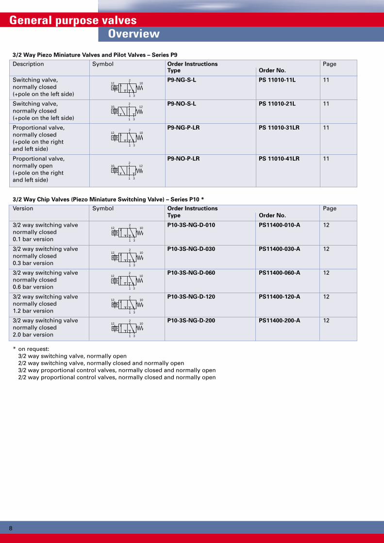
3/2 Way Piezo Miniature Valves and Pilot Valves – Series P9
Description Symbol Order Instructions PageType Order No.
Switching valve, P9-NG-S-L PS 11010-11L 11normally closed(+pole on the left side)
Switching valve, P9-NO-S-L PS 11010-21L 11normally closed(+pole on the left side)
Proportional valve, P9-NG-P-LR PS 11010-31LR 11normally closed(+pole on the rightand left side)
Proportional valve, P9-NO-P-LR PS 11010-41LR 11normally open(+pole on the rightand left side)
3/2 Way Chip Valves (Piezo Miniature Switching Valve) – Series P10 *
Version Symbol Order Instructions PageType Order No.
3/2 way switching valve P10-3S-NG-D-010 PS11400-010-A 12normally closed0.1 bar version
3/2 way switching valve P10-3S-NG-D-030 PS11400-030-A 12normally closed0.3 bar version
3/2 way switching valve P10-3S-NG-D-060 PS11400-060-A 12normally closed0.6 bar version
3/2 way switching valve P10-3S-NG-D-120 PS11400-120-A 12normally closed1.2 bar version
3/2 way switching valve P10-3S-NG-D-200 PS11400-200-A 12normally closed2.0 bar version
* on request:3/2 way switching valve, normally open2/2 way switching valve, normally closed and normally open3/2 way proportional control valves, normally closed and normally open2/2 way proportional control valves, normally closed and normally open
General purpose valvesOverview

9
2
1 3
12 10
2
1 3
10 12
321
3/2 Way Piezo Valves NW 2 – Series P20-OEM
Version Symbol Order Instructions PageType Order No.
Pilot valve, P20 381RF-NG-COEM PS10021-001A 13normally closed
Pilot valve, P20 381RF-NO-COEM PS10022-001A 13normally open
Base plate PS10531-A-01 31
Proportional Pressure Regulating Valve NW 2 – Series PR-U-OEM
Description Symbol Order Instructions PageType Order No.
Proportional pressure PR-U-OEM PS11193-A 14regulating valve
Base plate G1/8 PS11112-A-01 14
Base Plates see page 31

10
2
1 3
12 102
1 3
10 12
3
2
1
2
1 3
12 102
1 3
10 12
10
General purpose valvesActuator applications
In the following configurations piezo valves can be suppliedfor use in modern actuators.
Supply of P9 or P10 piezo chips as switching or proportional
pilot valves
These provide the user with the highest degree of flexibilityin the design of dedicated digital or analog actuator systems(IP converter with amplifier) as stand-alone devices or as partof large-scale positioning systems.
Supply of P20-OEM digital piezo valves consisting of piezo
chip (pilot valve) and volume amplifier
Supply of analog PR-U-OEM piezo valve consisting of piezo
chip (pilot valve) and proportional main valve
Customer-specific solutions
Complete development and delivery of customer-specificactuator control systems as part of a joint developmentproject.
HOERBIGER Interface provides a comprehensive supportpackage for the installation and application of all variants.
Piezo valvetype P9-NG-S-.
Piezo valvetype P9-NG-S-.
Piezo valvetype P20 381RF-NG-COEM
Piezo valvetype P20 381RF-NG-COEM
Piezoprop. pressure regulatingvalve PR-U-OEM
Customer-specific solution
Scope of supply of HOERBIGER products
Amplifier and actuator providedby customer
Scope of supply of HOERBIGER products
Actuator provided by customer
Scope of supply of HOERBIGER products
Actuator provided by customer

11
30
7,7
ø 1
4
1,2
11,7
19
12,6
11,7
0,8
20,6
11,7
3
1 3
1
2
2
***
11 10
14,1
+-
3
12
+- 3
12
General purpose valves3/2 Way Piezo Valve Series P9
* + pole on the right side**+ pole on the left side
Piezo ChipTyp:e P9-..-.-..
OFF ON
3/2 Way PiezoMiniature ValveandPilot ValveSeries P9
Versions– Proportional valve– Switching valve– NC or NO
Special Versions– Special pressure ranges– 2/2 way valve
Dimensions in mm
Characteristics Symbol Unit DescriptionGeneral Features
System Directly actuated 3/2 way proportionalpoppet valve
Housing PlasticMounting Flange (see dimensional drawing) **Port size = NW 0.33Weight g 6Flow direction ON: from 1 to 2
OFF: from 2 to 3Installation position OptionalAmbient ϑmin °C -30 Note:temperature range ϑmax °C +80 When using below freezing
point please contact ourtechnical department
Pneumatic CharacteristicsOperating pressure pN bar 1.2 (other pressures between 0 and 2 bar
on request)Nominal flow QN l/min 1.5Medium Filtered air (5 µ) *Leakage QL l/min On: 0.15 max
Off: 0.10 maxElectrical CharacteristicsOperating voltage UN V 24 DC ***
(other voltages on request)Capacity C nF < 100Switching energy E mWs 0.014Holding energy P W 0Switching time t ms < 2Connection Contact pins – ø 0.8 mm* other fluids on request** observe installation recommendations*** observe control recommendations

1212
1 2
3
1 2
3
1 2
3
23,5
12,5
4
4 26,9
2,6
33,5
ø3
38
22
242,6 27
2,0
3,8 2
8
3,8
163
20,5
General purpose valves... the “Chip Valve” Series P10
”Chip Valve”Piezo MiniatureValveSeries P10
Versions– 3/2 way switching valves
normally closed (NG)
Special Versions (4
(on request)–3/2 way switching valves
normally open (NO)–2/2 way switching valves–3/2 way proportional
control valves–2/2 way proportional
control valves (4normally closed andnormally open versions
Scope of supply–1 valve– Mounting kit consisting
of 3 rollers and O-rings– 2 M2.5 x 25 mm screws– 2 EJOT 2.5 x 6 screws–1 connecting cable
2 x 0.14, 300 mm,with connector
(1 Normally open (NO)version on request
(2 Nominal pressure pNagainst atmosphere
(3 Voltages < 24 V on request(not for prop. control valves)
(4 Characteristics on request(5 Not suitable as safety
valve with 100% ED
Characteristics Symbol Unit DescriptionGeneral FeaturesSystem Directly controlled (from system) propor-
tional control or switching poppet valveMounting Metal screws
(part of scope of supply)Connection Flange or nose nozzle (3 mm)Port size NW ca. 0.33Installation position OptionalWeight g 20Flow direction ON: from 1 to 2(normally closed NG) (1 OFF: from 2 to 3 (3/2-Way valve)Medium and ϑmin °C 0 other temperaturesambient temperature ϑmax °C +50 on requestrangeMedium Filtered air (30µ), other gases or fluids
possible on request
Pneumatic CharacteristicsValve nominal pressure pN bar 0.1 bar 0.3 bar 0.6 bar 1.2 bar 2.0 bar
Input pressure range p1 min/max bar 0.05–0.15 0.2–0.3 0,5–0.7 1.1–1.3 1.8–2.2Output pressure range p2 min/max bar 0–0.1 0–0.3 0–0.6 0–1.2 0–2.0(proportional version)Flowrate (23/2 way models Q l/min 0.5 0.9 1.5 1.5 1.4Leckage inlet air side 4% of Q
outlet air side: 8% of QElectrical CharacteristicsOperating volatage UN V 24 DC (proportional control valve 0 – 24 V DC)(3
Holding energy P W 0.006Connection 2-pin connectorRelative switching time ED % 100 (5
Electrical protection IP 20
Chip ValveType: P10-..-..-.-...
Flange mounting kitconsisting of 3 rollersand O-rings
for M2.5 x 25screws for EJOT 2.5x6 screws
on front and rear

13
32,55
M4
42,5
7,5
16
21
32,5
2
1
3
3/2 Way Piezo Valve Series P20-OEM
3/2 WayPiezo ValveSerie P20-OEMNW 2
Versions– normally closed (NG)– normally open (NO)
Note:The valve for the P20-OEMseries fulfils the requirementsfor approval as anintrinsically safe device whenused with an appropriatecontroller.
Series P20-OEM – NW 2.0
Characteristics Symbol Unit DescriptionGeneral Features
System Poppet valve system,pneumatic pilot control withpiezo valve, some overlap
Mounting Flange (see dim. drawing)Pipe connection FlangePort size NW2Weight (mass) kg 0.100Flow direction ON: from 1 to 2
OFF: from 2 to 3 (1
Installation position OptionalMedium and ϑmin. / max. °C -10 to +60ambient temperature Note: Contact technical depart-range ment advice if used in
temperatures between-30 and +80°C
Medium Dry or filtered air (30µ), no orminimal oil mist lubrication(max. 30mg/m3)
Pneumatic CharacteristicsNominal pressure pmin. / max. bar 6Operating pressure pmin. / max. bar 1.5 – 8Nominal flow QN l/min 130 (from 6 to 5 bar)Nominal size mm 2.0Electrical CharacteristicsNominal voltage UN V DC 24Capacity C nF < 100Switching energy E mWS 0.014Holding energy P W 0Duty cycle ED % 100Connection Cable 300 mm longSwitching time tON ms < 20 (10% of discharge pressure)
tOFF ms < 20 (90% of discharge pressure)Electrical protection IP 20 (2
(1 outlet air not included(2 not suitable as safety valve with 100% ED
Type: P20 381RF-.-COEM
Connecting cable 300 mm
Base plate see page 31

1414
32 20
7
25
14
15
4,5
M3
24,5
G1/8
G1/8
16
7,5
7,5
p2 (bar)
8
00 8 18 24
U(V)
20
36
67
17
24
37
2
1
3
14
51
(*
3
2
1
General purpose valvesProp. Pressure Regulating Valve Series PR-U-OEM
Pressure RegulatingValveSeries PR-U-OEMNW 2 and G1/8
Proportional valve withPiezo pilot
Note:The valve for the PR-U-OEMseries fulfils the require-ments for approval as anintrinsically safe devicewhen used with anappropriate controller.
Series PR-U-OEM – NW 2.5
Characteristics Symbol Unit DescriptionGeneral Features
Type Membrane pressureregulating valve, pneumaticpilot control with piezo valve,some overlap
Mounting Flange (see dim. drawing)Connection FlangePort size NW2.5Weight (mass) kg 0.100Flow direction ON: from 1 to 2
OFF: from 2 to 3 (1
Installation In any positionMedium and ϑmin. / max. °C -30 to +80ambient temperature Note:range When using below
freezing point it is necessaryto consult us.
Medium Dry or filtered air (30µ),no or minimal oil mistlubrication (max.30mg/m3)
Pneumatic CharacteristicsNominal pressure pmin. / max. bar 6Operating pressure pmin. / max. bar 1.5 – 10Nominal flow QN l/min 200 (from 6 to 5 bar)Nominal size mm 2.6Electrical CharacteristicsInput voltage U V DC 0 – 24 (3
Capacity C nF < 100Switching energy E mWS 0.014 (from 0 to 24 V)Holding energy P W 0Connection Connecting cable 200 mm
2-pin AMP connectorGrid size 2.54
Electrical protection IP 20(1 outlet air not included(2 The device should only be used in a closed control loop.
A 0-24 V DC controller should be provided (see U/P diagram).
A piezo valve is used asthe pilot control element.The piezo valve generatesa pilot pressure in the pilotchamber of the main valveproportional to the controlvoltage.The supply for the piezovalve is tapped off from thecontrol air connection 1 andpassed through a pressureregulator and filter.
Base Plate G1/8
Pressure Regulating ValveType: PR-U-OEM
The operating voltage rangeof the valve may fluctuatedue to temperature or long-term effects.A control range of 0 to 24 Vmust therefore be designedinto the controller.
1 = Pressure supply (P)2 = Outlet (A)3 = Exhaust (R)
(* Connecting cable 200 mm
Connection
Piezo valve
PressureRegulator
Microfilter U/P-Diagram

15
Directional Valves with NAMUR Connections

1616
4
5 3
2
1
14 12
4
5 3
2
1
14 12
2
1 3
1012
2
1 3
1012
144
5 3
2
1
12
4
5 3
2
1
1214
2
1 3
1012
2
1 3
10
4
14
2
1 3
10
4
14
Intrinsically safe 3/2, 4/2 and 5/2 Way Valves with NAMUR Connection – Series S29
Actuation Symbol Order Instructions PageType Order No.
Electrical, S29 385RF-1/4-.-NAMUR PS 13623-..6A 18by permanent signal
Electrical, S29 485RF-1/4-.-NAMUR PS 13621-..6A 18by permanent signal
Electrical, S29 585RF-1/4-.-NAMUR PS 13619-..6A 18by permanent signal
Electrical, S29 585-1/4-.-NAMUR PS 13620-..6A 21by impulse
Pilot valve as spare part P29 381 RF-NG-C. PS 10041-..1A –(electrical,by permanent signal)
Version Nominal voltage Type key Key code
Intrinsically safe 6 – 9 V DC M 54II 2G EEx ia IIC T4/T5/T6 7 – 16 V DC N 51
12 – 24 V DC L 5524 – 30 V DC E 21
3/2, 4/2 and 5/2 Way Valves with EEx m-Solenoids and NAMUR Connection – Series S9
Actuation Symbol Order Instructions PageType Order No.
Electrical, S9 381RF-1/4-NG-SO-.. PD 33854-..33 20by permanent signal
Electrical, S9 481RF-1/4-SO-.. PD 40996-..33 20by permanent signal
Electrical, S9 581RF-1/8-SO-.. PD 34143-..33 19by permanent signal S9 581RF-1/4-SO-.. PD 34985-..33 20
Electrical, S9 581-1/8-SO-.. PD 34984-..33 19by impulse S9 581-1/4-SO-.. PD 34986-..33 20
Solenoid version Nominal voltage Key code
Casting cover 24V = 48EEx m II T5 220V/50(60) Hz 98
other voltages on request
Directional Valves with NAMUR ConnectionsOverview
17
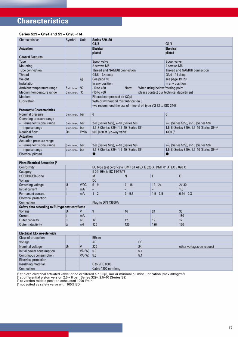
Series S29 – G1/4 and S9 – G1/8 -1/4
Characteristics Symbol Unit Series S29, S9G1/8 G1/4
Actuation Electrical Electrical
piloted piloted
General Features
Type Spool valve Spool valveMounting 2 screws M5 2 screws M6Tube connection Thread and NAMUR connection Thread and NAMUR connectionThread G1/8 – 7.4 deep G1/4 – 11 deepWeight kg See page 18 see page 19, 20Installation In any position in any positionAmbient temperature range ϑmin. / max. °C -10 to +60 Note: When using below freezing pointMedium temperature range ϑmin. / max. °C -10 to +60 please contact our technical departmentMedium Filtered compressed air (30µ)Lubrication With or without oil mist lubrication (1
(we recommend the use of mineral oil type VG 32 to ISO 3448)Pneumatic Characteristics
Nominal pressure pmin. / max. bar 6 6Operating pressure range– Permanent signal range pmin. / max. bar 2–8 (Series S29), 2–10 (Series S9) 2–8 (Series S29), 2–10 (Series S9)– Impulse range pmin. / max. bar 1.5–8 (Series S29), 1.5–10 (Series S9) 1.5–8 (Series S29), 1.5–10 (Series S9) (2
Nominal flow QN l/min 500 (450 at 3/2-way valve) 1300 (3
Actuation
Actuation pressure range– Permanent signal range pmin. / max. bar 2–8 (Series S29), 2–10 (Series S9) 2–8 (Series S29), 2–10 (Series S9)– Impulse range pmin. / max. bar 1.5–8 (Series S29), 1.5–10 (Series S9) 1.5–8 (Series S29), 1.5–10 (Series S9) (2
Electrical piloted
Piezo Electrical Actuation (4
Conformity EU type test certificate DMT 01 ATEX E 025 X, DMT 01 ATEX E 026 XCategory II 2G EEx ia IIC T4/T5/T6HOERBIGER-Code M N L EVoltage DCSwitching voltage U V/DC 6 – 9 7 – 16 12 – 24 24-30Initial current I mA – – – 1,6Permanent currant I mA 1 – 2 2 – 5.5 1.5 – 3.5 0.24 – 0.3Electrical protection Connection Plug to DIN 43650ASafety data according to EU type test certificate
Voltage Ui V 9 16 24 30Current Ii mA – – – 150Outer capacity Ci nF 12 12 12 12Outer inductivity Li nH 120 120 120 120
Electrical, EEx m-solenoids
Class of protection EEx mVoltage AC DCNominal voltage Un V 220 24 other voltages on requestInitial power consumption VA (W) 5.0 5.1Continuous consumption VA (W) 5.0 5.1Electrical protection Insulating material E to VDE 0580Connection Cable 1200 mm long
(1 at piezo electrical actuated valve: dried or filtered air (30µ), nor or minimal oil mist lubrication (max.30mg/m3)(2 at differential piston version 2.5 – 8 bar (Series S29), 2.5–10 (Series S9)(3 at version middle position exhausted 1000 l/min(4 not suited as safety valve with 100% ED
Characteristics

1818
22 83,5
121,
5
52
80
~ 2
16
12
14
19,5
57,5
~ 1
40
3
1
G1/
4
40,5
12
2429
,5
32
32
6
35,2
2
19,5
2222
105,
5
143,
5
52
80
~ 2
37
12
14
19,5
57,5
~ 1
62
3
4
2
5
1
3
G1/
4
40,5
5,2
12
2430
,5
32
19,5
32
6
3/2, 4/2 and5/2 Way ValveSeries S29G1/4
with NAMUR connections
Actuation:– Piezo electric actuated
3/2 Way valveType: S29 385RF-1/4-.- Namur
4/2 and 5/2 Way ValveType: S29 4(5)85RF-1/4-.- Namur, S29 585-1/4-.- Namur
Weight (mass) kg
Description Type Weight (mass)Electrical, by perm. signal S29 385RF-1/4-.-NAMUR 0.460Electrical, by perm. signal S29 485RF-1/4-.-NAMUR 0.550Electrical, by perm. signal S29 585RF-1/4-.-NAMUR 0.550Electrical, by impulse S29 585-1/4-.-NAMUR 0.650
The delivery includes:1 Valve2 Mounting screws1 Coding pin2 O-rings
Order Instructions see page 16, Characteristics see page 17
Directional Valves with NAMUR ConnectionsSeries S29 – intrinsically safe, piezo electrical actuated
5.5
x 3
deep
5,5
x 3
deep
only atimpulse valves
only atimpulse valves

19
19
15,5
40
~71
1
3
12
1418
87,5
33,5
15,5
128
56
5
18
2816
G1/
8
4
2
19,55,
2
2422
12
3
4
32
22
~ 1
40
~ 2
08
*
*
30
5/2 Way ValveSeries S9G1/8
with NAMUR connections
Actuation:EEx m-solenoids–Electrical pilot operation
The delivery includes:1 Valve2 Mounting screws1 Coding pin2 O-rings
Weight (mass) kg
Description Type Weight (mass)Electrical, by perm. signal S9 581RF-1/8-.. 0.280Electrical, by impulse S9 581-1/8-.. 0.415
Order Instructions see page 16, Characteristics see page 17P-supply and RPS manifolds see page 41, 42, 46
Dimensions in mm
Series S9 – with EEx m-Solenoids
5/2 Way valveType: S9 581RF-1/8-SO-.., S9 581-1/8-SO-..
impulse valves only
* Manual override
5.5
x 3
deep

2020
2222
106
148
15,5
52
~ 71
12
20
62*
*
14
9
3
4
2
5
1
3
20,7
5,2
12
32,7
2430
,5
32
19,5
G1/
4
41
30
32
12
~ 1
59
~ 2
31
22 83,5
121,
5
52
~ 71
~ 2
16
12
14
19,5
57,5
~ 1
40
3
1
G1/
4
40,5
12
2429
,5
32
32
35,2
2
19,5
30
Directional Valves with NAMUR ConnectionsSeries S9 – with EEx m-Solenoids
3/2, 4/2 and5/2 Way ValveSeries S9G1/4
with NAMUR connections
Actuation:EEx m-Solenoids– Electrical pilot operation
The delivery includes:1 Valve2 Mounting screws1 Coding pin2 O-rings
3/2 Way valveType: S9 381RF-1/4-SO-..
4/2 and 5/2 Way valveType: S9 4(5)81RF-1/4-SO-..,S9 581-1/4-SO-..
Order Instructions see page 16, Characteristics see page 17P-supply and RPS manifolds see page 43,44,47
Weight (mass) kg
Description Type Weight (mass)Electrical, by perm. signal S9 381RF-1/4-.. 0.500Electrical, by perm. signal S9 481RF-1/4-.. 0.600Electrical, by perm. signal S9 581RF-1/4-.. 0.600Electrical, by impulse S9 581-1/4-.. 0.700
impulsevalves only
* Manual override
*
*
5.5
x 3
deep
* Manual override
impulsevalves only
5.5
x 3
deep

21
Directional Valves, intrinsically safe and with EEx m-Solenoids

22
2
1 3
12 10
2
1 3
12 10
2
1 3
10 12
2
1 3
12 10
2
1 3
12 10
2
1 3
10 12
22
Version Nominal voltage Type key Key code
Intrinsically safe 6 – 9 V DC M 54II 2G EEx ia IIC T4/T5/T6 7 – 16 V DC N 51
12 – 24 V DC L 5524 – 30 V DC E 21
3/2 Way Poppet Valves (Pilot and Single Valves) – Series P8
Actuation Symbol Port size Order Instructions PageType Order No.
Pilot valve (1 NW 1.6 P8 381RF-NG-S. PS 11001-..0A 30normally closed
normally open NW 1.6 P8 381RF-NO-S. PS 10002-..0A 30
Single valve M5 (2 M5 P8 381RF-M5 NG-S. PS 11003-..0A-01 30normally closed
(1 without base plate and without plug(2 with plug and with base plate
Directional Valves – intrinsically safe, piezo electrically actuated, Series P8, P20 – M5 to G1/8Overview and Order Instructions
3/2 Way Poppet Valves (Pilot and Single Valve) – Series P20
Actuation Symbol Port size Order Instructions PageType Order No.
Pilot valve (1 NW 2 P20 381RF-NG-C. PS 10021-..1A 31normally closed
normally open NW 2 P20 381RF-NO-S. PS 10022-..1A-01 31
Single valve G1/8 (2 G1/8 P20 381RF-1/8NG-C. PS 10023-..1A-01 31normally closed
(1 without base plate and without plug(2 with plug and with base plate
Series P8
Description Type Order No.
Base plate for 1 valve PS11614-A-01
Base plate for 2 valves PS11614-A-02
Base plate for 4 valves PS11614-A-04
Base plate for 6 valves PS11614-A-06
Base plate for 8 valves PS11614-A-08
Base plate for 10 valves PS11614-A-10
Blanking plate, complete PS11530-A
Plug GSD-22 KY9393
Version Nominal voltage Type key Key code
Intrinsically safe 6 – 9 V DC M 54II 2G EEx ia IIC T4/T5/T6 7 – 16 V DC N 51
12 – 24 V DC L 5524 – 30 V DC E 21
Series P20
Description Type Order No.
Base plate for 1 valve PS10531-A-01
Base plate for 2 valves PS10531-A-02
Base plate for 4 valves PS10531-A-04
Base plate for 6 valves PS10531-A-06
Base plate for 8 valves PS10531-A-08
Base plate for 10 valves PS10531-A-10
Blanking plate, complete PS10559-A
Plug GSD-30 KY5637
Base Plates and Accessories for Series P8 and P20

2323
4
5 3
2
1
14 12
4
5 3
2
1
14 12
4
5 3
2
1
14 12
4
5 3
2
1
14 12
4
5 3
2
1
14 12
124
5 3
2
1
14
2
1 3
10
2
1 3
12 10
4
5 3
2
1
14 12
4
5 3
2
1
14 12
4
5 3
2
1
14 12
4
5 3
2
1
14 12
4
5 3
2
1
14 12
Directional Valves – intrinsically safe, piezo electrically actuated, Series S9-G1/8, G1/4, S20- ISO 1, 2, 3Overview and Order Instructions
3/2 Way Valves – Series S9
Actuation Symbol Order Instructions PageType Order No.
Electrical, S9 385RF-1/4-. PS 13204-..6A 32by permanent signal
Electrical, S9 385-1/4-. PS 13200-..6A 32by impulse
5/3 Way Valves – Series S9
Actuation Symbol Order Instructions PageType Order No.
Electrical, by permanent S9 585RFG-1/8-. PS 13108-..6A 33signal with spring return S9 585RFG-1/4-. PS 13212-..6A 34to middle position
Electrical, by permanent S9 585RFE-1/8-. PS 13109-..6A 33signal with spring return S9 585RFE-1/4-. PS 13213-..6A 34to middle position
Electrical, by permanent S9 585RFB-1/8-. PS 13110-..6A 33signal with spring return S9 585RFB-1/4-. PS 13214-..6A 34to middle position
5/2 Way Valves – Series S9
Actuation Symbol Order Instructions PageType Order No.
Electrical, S9 585RRF-1/8-. PS 13118-..6A 33by permanent signal S9 585RF-1/4-. PS 13210-..6A 34
Electrical, S9 585-1/8-. PS 13104-..6A 33by impulse S9 585-1/4-. PS 13222-..6A 34
5/2 and 5/3 Way Valves to ISO 5599 – Sizes 1, 2, 3 – Series S20
Actuation Symbol Order Instructions PageType Order No.
Electrical, S20 585RF-1-.. PS 13704-..1A 35by permanent signal, S20 585RF-2-.. PS 13724-..1Aspring return S20 585RF-3-.. PS 13744-..1A
Electrical, S20 585R-1-.. PS 13702-..1A 35by permanent signal, S20 585R-2-.. PS 13722-..1Aair spring return S20 585R-3-.. PS 13742-..1A
Electrical, S20 585-1-.. PS 13700-..1A 35by impulse S20 585-2-.. PS 13720-..1A
S20 585-3-.. PS 13740-..1A
S20 585RFG-1-.. PS 13706-..1A 35S20 585RFG-2-.. PS 13726-..1AS20 585RFG-3-.. PS 13746-..1A
S20 585RFB-1-.. PS 13710-..1A 35S20 585RFB-2-.. PS 13730-..1A
S20 585RFE-1-.. PS 13708-..1A 35S20 585RFE-2-.. PS 13728-..1AS20 585RFE-3-.. PS 13748-..1A
Version Nominal voltage Type key Key code
Intrinsically safe 6 – 9 V DC M 54II 2G EEx ia IIC T4/T5/T6 7 – 16 V DC N 51
12 – 24 V DC L 5524 – 30 V DC E 21
Electrical,by permanent signal,with spring returnto middle position

24
2
1 3
1012
2
1 3
1210
12
3
2
1
14
stp
2
1 3
12 10
2
1 3
14 12
pst
2
1 3
14 12
pst
2
1 3
12 10
2
1 3
12 10
21012
1 3
144
5 3
2
1
12
124
5 3
2
1
14
stp
4
5 3
2
1
1214
4
5 3
2
1
14 12
pst pst
4
5 3
2
1
14 12
4
5 3
2
1
14 12
stp stp
2
1 3
14 12
pst pst
24
Solenoid version Nominal voltage Key code
EX-proof version 24V = 48220V/50(60) Hz 98
Further voltages available on request
3/2 Way Valves – Standard Versions with EX-Proof-Solenoids
Actuation Symbol Order Instructions PageType Order No.
Electrical, S9 381RF-1/8-NG-.. PA 10297-..33 37by permanent signal S9 381RF-1/4-NG-.. PA 12716-..33
S9 381RF-1/2-NG-.. PA 16412-..33
S9 381RF-1/8-NO-.. PA 10298-..33 37S9 381RF-1/4-NO-.. PA 12717-..33S9 381RF-1/2-NO-.. PA 16413-..33
with external pilot air S9 381S-RF-1/8-.. PA 10300-..33 37S9 381S-RF-1/4-.. PA 12719-..33S9 381S-RF-1/2-.. PA 16415-..33
Electrical, S9 381-1/8-.. PA 10299-..33 37by impulse S9 381-1/4-.. PA 12718-..33
S9 381-1/2-.. PA 16414-..33
Electrical, S9 381S-1/8-.. PA 10301-..33 37by impulse S9 381S-1/4-.. PA 12720-..33with external pilot air S9 381S-1/2-.. PA 16417-..33
Electrical, S9 382-1/4-.. PA 12721-..33 37by impulse, S9 382-1/2-.. PA 16418-..33differential piston
with external pilot air S9 382S-1/4-.. PA 12722-..33 37S9 382S-1/2-.. PA 16419-..33
Electrical, NW 1.3 V9 381RF-1/8-NG-.. PA 10362-..33 36by permanent signal
NW 1.3 V9 381H-RF-1/8-NG-.. PA 10363-..33 36
NW 1.3 V9 381H-RF-1/8-NO-.. PA 10367-..33 36
5/2 Way Valves – Standard Versions with EX-Proof-Solenoids
Actuation Symbol Order Instructions PageType Order No.
Electrical, S9 581RF-1/8-.. PA 10312-..33 38by permanent signal S9 581RF-1/4-.. PA 12679-..33
S9 581RF-1/2-.. PA 16171-..33
with external pilot air S9 581S-RF-1/8-.. PA 10314-..33 38S9 581S-RF-1/4-.. PA 12681-..33S9 581S-RF-1/2-.. PA 16174-..33
Electrical, S9 581-1/8-.. PA 10313-..33 38by impulse S9 581-1/4-.. PA 12680-..33
S9 581-1/2-.. PA 16172-..33
with external pilot air S9 581S-1/8-.. PA 10315-..33 38S9 581S-1/4-.. PA 12682-..33S9 581S-1/2-.. PA 16175-..33
Electrical, S9 582-1/4-.. PA 12683-..33 38by impulse, S9 582-1/2-.. PA 16173-..33differential piston
with external pilot air S9 582S-1/4-.. PA 12684-..33 38
Directional Valves – with EEx m-Solenoids, Series S9 (V9) – G1/8 to G1/2Overview and Order Instructions

25
4
5 3
2
1
14 12
4
5 3
2
1
1214
4
5 3
2
1
1214
5/3 Way Valves – Standard Versions with EX-Proof-Solenoids
Actuation Symbol Order Instructions PageType Order No.
S9 581RFG-1/8-.. PA 10333-..33 39S9 581RFG-1/4-.. PA 12705-..33S9 581RFG-1/2-.. PA 16176-..33
S9 581RFE-1/8-.. PA 10334-..33 39S9 581RFE-1/4-.. PA 12706-..33S9 581RFE-1/2-.. PA 16177-..33
S9 581RFB-1/8-.. PA 10335-..33 39S9 581RFB-1/4-.. PA 12707-..33S9 581RFB-1/2-.. PA 16178-..33
Solenoid version Nominal voltage Key code
EX-proof version 24V = 48220V/50(60) Hz 98
Further voltages available on request
Directional Valves – with EEx m-Solenoids, Series S9 – G1/8 to G1/2Overview and Order Instructions
Electrical,by permanent signalwith spring returnto middle position

26
4
5 3
2
1
1214
124
5 3
2
1
14
stp
144
5 3
2
1
12
124
5 3
2
1
14
4
5 3
2
1
14 12
pst pst
4
5 3
2
1
1214
4
5 3
2
1
1214
4
5 3
2
1
14 12
4
5 3
2
1pst pst
14 12
4
5 3
2
1pst pst
14 12
4
5 3
2
1pst pst
14 12
26
5/2 Way Valves – Standard Version with EX-Proof-Solenoids to ISO 5599 – Sizes 1, 2, 3
Actuation Symbol Order Instructions PageType Order No.
Electrical, S20 581RF-1-.. PA 12875-..33 40by permanent signal S20 581RF-2-.. PA 16441-..33with spring return S20 581RF-3-.. PA 16442-..33
with external pilot air S20 581S-RF-1-.. PA 12882-..33 40S20 581S-RF-2-.. PA 16456-..33S20 581S-RF-3-.. PA 16462-..33
Electrical, S20 581R-1-.. PA 12876-..33 40by permanent signal S20 581R-2-.. PA 16444-..33with air spring return S20 581R-3-.. PA 16445-..33
Electrical, S20 581-1-.. PA 12874-..33 40by impulse S20 581-2-.. PA 16438-..33
S20 581-3-.. PA 16439-..33
with external pilot air S20 581S-1-.. PA 12880-..33 40S20 581S-2-.. PA 16454-..33S20 581S-3-.. PA 16460-..33
5/3 Way Valves – Standard Version with EX-Proof-Solenoids to ISO 5599 – Sizes 1, 2, 3
Actuation Symbol Order Instructions PageType Order No.
S20 581RFG-1-.. PA 12877-..33 40S20 581RFG-2-.. PA 16447-..33S20 581RFG-3-.. PA 16448-..33
S20 581RFB-1-.. PA 12879-..33 40S20 581RFB-2-.. PA 16453-..33
S20 581RFE-1-.. PA 12878-..33 40S20 581RFE-2-.. PA 16450-..33S20 581RFE-3-.. PA 16451-..33
with external pilot air S20 581S-RFG-1-.. PA 12883-..33 40S20 581S-RFG-2-.. PA 16457-..33S20 581S-RFG-3-.. PA 16463-..33
S20 581S-RFB-1-.. PA 12885-..33 40S20 581S-RFB-2-.. PA 16459-..33
S20 581S-RFE-1-.. PA 12884..33 40S20 581S-RFE-2-.. PA 16458..33S20 581S-RFE-3-.. PA 16464..33
Solenoid version Nominal voltage Key code
EX-proof version 24V = 48220V/50(60) Hz 98
Further voltages available on request
Directional Valves to ISO 5599 – with EEx m-Solenoids, Series S20Overview and Order Instructions
Electrical,by permanent signalwith spring returnto middle position

27
Directional Valves – intrinsically safe, piezo electrically actuated, Series P8, P20Characteristics
Series P8 – NW1.6 and M5, P20 – NW 2.0 and G1/8
Characteristics Symbol Unit Series P8 Series P20NW 1.6 and M5 NW 2.0 and G1/8
Actuation piezo electrical piezo electricalpiloted piloted
General Features
Type Piezo poppet valve, some overlap Piezo poppet valve, some overlapMounting Flange (see dimensional drawing) Flange to CNOMO (see dimensional drawing)Tube connection Flange / Thread Flange / ThreadThread M5 – with base plate G1/8 – with base plateWeight kg 0.050 (pilot valve) . 0.080 (pilot valve)Flow direction ON: from 1 to 2 OFF: from 2 to 3 ON: from 1 to 2 OFF: from 2 to 3Installation In any position In any positionAmbient temperature range (1 ϑmin. / max. °C -10 to +60 -10 to +60Medium temperature range (1 ϑmin. / max. °C -10 to +60 -10 to +60Medium Filtered air (30µ), nor or minimal oil mist lubrication (max.30mg/m3) (2
(we recommend the use of mineral oil type VG 32 to ISO 3448)Pneumatic Characteristics
Nominal pressure pmin. / max. bar 6 6Operating pressure range pmin. / max. bar 1.2 – 8 1.2 – 8Nominal flow QN l/min 50 b = 0,34; C = 12,5 l/min bar) 110 b = 0.33; C = 26.5 l/min bar)Nominal size mm 1.6 2.0
Piezo Electrical Actuation (2
Approval EU type test certificate DMT 01 ATEX E 026 X / DMT 01 ATEX E 025 XCategory, type of protection II 2G EEx ia IIC T4/T5/T6HOERBIGER Code M N L EVoltage DCSwitching voltage * U V/DC 6 – 9 7 – 16 12 – 24 24 – 30Initial current I mA – – – 1.6Holding current I mA 1 – 2 2 – 5.5 1.5 – 3.5 0.24 – 0.3Electrical protection IP54Connection Plug to DIN 43650ASafety data according to EU type test certificate
Voltage Ui V 9 16 24 30Current Ii mA – – – 150External capacitance Ci nF 12 12 12 12External inductance Li nH 120 120 120 120
(1 Note: When using below freezing point please contact our technical department.(2 Not suitable as safety valve with 100% ED

2828
28
Directional Valves – intrinsically safe, piezo electrical and electrical actuated, Series V9, S9Characteristics
Series S9 – G1/8 to G1/2, Series V9-G1/8
Characteristics Symbol Unit Series V9 Series S9G1/8 G1/8 G1/4 G1/2
Actuation Electrical electrical piloted or electrical piloted or electricaldirect piezo electrical piloted piezo electrical piloted piloted
General Features
Type Poppet valve Spool valve Spool valve Spool valveMounting 2 screws M3 2 screws M5 2 screws M6 2 screws M6Tube connection Thread Thread Thread ThreadThread G1/8–8 deep G1/8 – 7.4 deep G1/4 – 11 deep G1/2 – 16 deepWeight kg 0.140 see page 33, 37-39 see page 32, 34, 37-39 see page 37-39Installation in any position in any position in any position in any positionAmbient temperature range (1 ϑmin. / max. °C -10 to +60 -10 to +60 -10 to +60 -10 to +60Medium temperature range (1 ϑmin. / max. °C -10 to +60 -10 to +60 -10 to +60 -10 to +60Medium Filtered compressed air (30µ)Lubrication With or without oil mist lubrication (2
(we recommend the use of mineral oil type VG 32 to ISO 3448)Pneumatic Characteristics
Nominal pressure pmin. / max. bar 6 6 6 6Operating pressure range pmin. / max. bar– Permanent signal range pmin. / max. bar 0–10 2–10 2–10 2.2–10Impulse range pmin. / max. bar – 1.5–10 1.5–10 (3 1.5–10 (3
– with external pilot air pmin. / max. bar – 0–10 0–10 0–10Nominal flow QN l/min 37 (150 NW2.5) 500 (450 at 3/2 way valve) 1300(4 3500(5
Actuation
Actuation pressure range– Permanent signal range pmin. / max. bar – 2–10 2–10 2.2–10Impulse range pmin. / max. bar – 1.5–10 1.5–10 (3 1.5–10 (3
– with external pilot air pmin. / max. bar – 0–10 0–10 0–10– electrical direct
piloted –
piloted, with external –
pilot air
Piezo Electrical Actuation (6
Approval EU type test certificate DMT 01 ATEX E 026 XCategory, type of protection II 2G EEX ia IIC T4/T5/T6HOERBIGER Code M N L EVoltage DCSwitching voltage U V/DC 6 – 9 7 – 16 12 – 24 24 – 30Initial current I mA – – – 1.6Holding current I mA 1 – 2 2 – 5.5 1.5 – 3.5 0.24 – 0.3Electrical protection IP54Connection Plug to DIN 43650ASafety data according to EU type test certificate
Voltage Ui V 9 16 24 30Current Ii mA – – – 150External capacitance Ci nF 12 12 12 12External inductance Li nH 120 120 120 120
Electrical, by EX solenoids
Voltage AC DCNominal voltage Un V 220 24 other voltages on requestSwitching energy VA (W) 5.0 5.1Holding energy VA (W) 5.0 5.1Electrical protection Insulation material E to VDE 0580Connection Cable 1200 mm long
(1 Note: when using below freezing point please contact our technicaldepartment.
(2 at piezo electrical piloted valve: filtered air (30µ),nor or minimal oil mist lubrication (max. 30mg/m3)
(3 at differential piston version 2.5 – 10 bar
(4 at version middle position exhausted 1000 l/min(5 at version middle position exhausted 3300 l/min
at version middle position pressurized 3600 l/min(6 Not suitable as safety valve with 100% ED

29
Directional Valves to ISO 5599 – intrinsically safe, piezo electrical and electrical actuated, Series S20
Series S20 according to IS0 5599 Sizes 1, 2, 3
Characteristics Symbol Unit Series S9ISO 1 ISO 2 ISO 3
Actuation electrical electrical electricalpiloted piloted piloted
General Features
Type Ceramic spool valveMounting On base plate – to VDMA 24561 Gr. 01 and ISO 5599 Gr. 1, 2, 3Tube connection Base plateBase plate-Thread G1/4 G3/8 G1/2Weight– Permanent signal range kg 0.460 0.700 1.230– Impulse range kg 0.590 0.830 1.370Installation In any positionAmbient temperature range (1 ϑmin. / max. °C -10 to +60 -10 to +60 -10 to +60Medium temperature range (1 ϑmin. / max. °C -10 to +60 -10 to +60 -10 to +60Medium Filtered compressed air (30µ)Lubrication With or without oil mist lubrication (2
(we recommend the use of mineral oil type VG 32 to ISO 3448)Pneumatic Characteristics
Nominal pressure pmin. / max. bar 6Operating pressure range pmin. / max. bar– Permanent signal range pmin. / max. bar 2–12 16 bar versions– Impulse range pmin. / max. bar 2–12 on request– with external pilot air pmin. / max. bar -1–12Nominal flow QN l/min 1380 3720 6660Actuation
Actuation pressure range– Permanent signal range pmin. / max. bar 2–10 16 bar versions– Impulse range pmin. / max. bar 2–10 on request– with external pilot air pmin. / max. bar 2–10electrical piloted – with external pilot air
Piezo Electrical Actuation (3
Approval EU type test certificate DMT 01 ATEX E 025 XCategory, type of protection II 2G EEX ia IIC T4/T5/T6HOERBIGER Code M N L EVoltage DCSwitching voltage U V/DC 6 – 9 7 – 16 12 – 24 24 – 30Initial current I mA – – – 1.6Holding current I mA 1 – 2 2 – 5.5 1.5 – 3.5 0.24 – 0.3Electrical protection IP54Connection Plug to DIN 43650ASafety data according to EU type test certificate
Voltage Ui V 9 16 24 30Current Ii mA – – – 150External capacitance Ci nF 12 12 12 12External inductance Li nH 120 120 120 120
Electrical, by EX solenoids
Voltage AC DCNominal voltage Un V 220 24 other voltages on requestSwitching energy VA (W) 5.0 5.1Holding energy VA (W) 5.0 5.1Electrical protection Insulation material E to VDE 0580Connection Cable 1200 mm long
(1 Note: when using below freezing point please contact our technicaldepartment.
(2 at piezo electrical piloted valve: filtered air (30µ),nor or minimal oil mist lubrication (max. 30mg/m3)
(3 Not suitable as safety valve with 100% ED

30
ca.72
21,6
40
10
44
ca.6
3
1
22
2
ø4,5
5
12
9
M5
2320.5
ø20,5
n x 23 + 18
n x 23 + 9 4,5
222
6 tief
11
16432
72
40
33
1,5
ca.50
321
4
M3
1,6
22
1
ca.72
20
5
2 x ø4,5
40
40
8
M5
10
44 ca
.63
22
12
22
32
30
3/2 Way Valves (Pilot Valves with Base Plate)Series P8 – intrinsically safe, piezo electrical actuated
Single ValveType: P8 381RF-M5 NG(NO)-.
Manifold VersionType: P8 381RF-M5 NG(NO)-S.
Versions– Pilot valve NW1.6– Single valve M5– Manifold version M5– Normally closed– Normally open
3/2 WayPoppet ValveSeries P8NW 1.6 and M5Actuation:– Piezo electric piloted
n = Number of valvesBase plates shouldbe ordered separately
Pilot ValveType: P8 381RF-NG(NO)-.
6 deep
Order Instructions see page 22, Characteristics see page 27

31
32,5
38
5
M4
50
77,5
ca.50
7,5
16
21
32,5
2
1
3
*
77,5
15
9
24,5
30
ca.7
5
63
57,5
1
9
34
ø4,5
4,6
ø8
2
3
1
25
21
15
15,5
32,5 *
G1/8
8 tief
G1/
8
8 tie
f
77,5
15
9
24,5
30
25
ca.7
5
63
57,5
1
9
6,5
17
3417
15
ø4,5
4,6
ø8
2 2 2
15,5
21
3
1
6,5
32,5 *
G1/8
8 tief
G1/8
8 tief
34 x Anzahl der Ventile
* Handnotbetätigung
Series P20 – intrinsically safe, piezo electrical actuated
Dimensions in mm
3/2 WayPoppet ValveSeries P20NW 2 and G1/8Actuation:–Piezo electric piloted
Versions–Pilot valve NW2–Single valve G1/8–Manifold version G1/8–Normally closed–Normally open
Pilot ValveType: P20 381RF-NG(NO)-.
Single ValveType: P20 381RF-1/8 NG(NO)-.
* Manual override
* Manual override
Manifold VersionType: P20 381RF-1/8 NG(NO)-.
n = Number of valvesBase plates shouldbe ordered separately
Order Instructions see page 22, Characteristics see page 27

3232
72
40
~ 5
0
1,6
G 1
/4
22
47
52
2
1
3
10
12
28,5
41
11
5,5
(1)
(3)
(10) 25
o 4,
2
o 7,
5
72
40
~ 5
0
1,6
84
32
22
*
*
4,56,5
6
(12)
~ 2
04
Weight (mass) kg
Description Type Weight (mass)Electrical, by perm. signal S9 585RF-1/4-.. 0.500Electrical, by impulse S9 585-1/4-.. 0.600 *Manual override
3/2 Way ValveType: S9 385RF-1/4-., S9 385-1/4-.
3/2 Way ValveSeries S9G1/4Actuation:– Piezo electric piloted
3/2 Way ValveSeries S9 – intrinsically safe, piezo electrical actuated
Order Instructions see page 23, Characteristics see page 28P-Supply and RPS Manifolds see pages 43, 44, 47
only atimpulse valves

33
3,2
5,6
18
55,5
42
40
72
1
5
12
14G
1/8
~ 2
08
5,5
3323,5
87
4
8 5
3
218
18
5
136
5424
,5
15
49
~ 1
40
*
*
22
4
*
3,2
5,6
18
55,5
42
40
72
1
5
12
14
G1/
8
~ 2
08
5,5
3323,5
87
4
8 5
3
218
18
5
136
5424
,5
15
49
~ 1
40
*
22
4
Dimensions in mm
5/2 and5/3 Way ValveSeries S9G1/8Actuation:– Piezo electric piloted
*Manual override
5/2 Way ValveType: S9 585RF-1/8-., S9 585-1/8-.
*Manual override
5/3 Way ValveType: S9 585RF.-1/8-.
Weight (mass) kg
Description Type Weight (mass)Electrical, by perm. signal S9 585RF-1/8-.. 0.245Electrical, by impulse S9 585-1/8-.. 0.340Electrical, by perm. signal * S9 585RF.-1/8-.. 0.340
*Middle position variants RFG, RFE, RFB
Order Instructions see page 23, Characteristics see page 28P-Supply and RPS Manifolds see pages 41, 42, 46
5/2 and 5/3 Way ValveSeries S9 – intrinsically safe, piezo electrical actuated
only at impulse valves

3434
22
G 1
/4
2222
67
105,
5
140
51,5
2
4
5
1
3
52
72
~ 2
31
12
14
29,5
29
40,5
66
6,5
6
4,5
G1/
8
22
32
11
5,5
19,5
25
54
~ 1
59
o 4,
2
o 7,
5
*
*
22
G 1
/4
2222
67
105,
5
140
51,5
2
4
5
1
3
52
72
~ 2
31
12
14
29,5
29
40,5
66
6,5
6
4,5
G1/
822
32
11
5,5
19,5
25
54
~ 1
59
o 4,
2
o 7,
5
*
*
5/2 and5/3 Way ValveSeries S9G1/4Actuation:– Piezo electric piloted
Weight (mass) kg
Description Type Weight (mass)Electrical, by perm. signal S9 585RF-1/4-.. 0.550Electrical, by impulse S9 585-1/4-.. 0.650Electrical, by perm. signal * S9 585RF.-1/4-.. 0.620
*Middle position variants RFG, RFE, RFB
Order Instructions see page 23, Characteristics see page 28P-Supply and RPS Manifolds see pages 43, 44, 47
*Manual override
5/2 Way ValveType: S9 585RF-1/4-., S9 585-1/4-.
*Manual override
5/3 Way ValveType: S9 585RF.-1/4-.
5/2 and 5/3 Way ValveSeries S9 – intrinsically safe, piezo electrical actuated

35
54
12
3
54
58
140
SW
5*
113
212
102
195
SW
4*
54
12
3
42
46
120
54
12
3
68
71
170
126
229
SW
6*
Dimensions in mm
Way Valve to ISO 5599Series S20 – intrinsically safe, piezo electrical actuated
5/2 and5/3 Way ValveSeries S20to ISO 5599Sizes 1, 2, 3Actuation:– Piezo electric piloted
5/2 and 5/3 Way Valve to ISO 5599 Size 2Type: S20 585..-2-.., S20 585RF.-2-..
*Manual override
5/2 and 5/3 Way Valve to ISO 5599 Size 1Type: S20 585..-1-.., S20 585RF.-1-..
*Manual override
Weight (mass) kg
Description Type Weight (mass)Electrical, by perm. signal S20 585RF(R)-1-.. 0.460Electrical, by impulse S20 585-1-.. 0.590Electrical, by perm. signal * S20 585RF.-1-.. 0.590Electrical, by perm. signal S20 585RF(R)-2-.. 0.700Electrical, by impulse S20 585-2-.. 0.830Electrical, by perm. signal * S20 585RF.-2-.. 0.830Electrical, by perm. signal S20 585RF(R)-3-.. 1.230Electrical, by impulse S20 585-3-.. 1.370Electrical, by perm. signal * S20 585RF.-3-.. 1.370
*Middle position variants RFG, RFE, RFB
*Manual override
5/2 and 5/3 Way Valve to ISO 5599 Size 3Type: S20 585..-3-.., S20 585RF.-3-..
Order Instructions see page 23, Characteristics see page 29Base Plates see pages 48-51
3636
22
16,6
G1/8
8
8
3,2
12
30
17
40
25
55
ø5
,6
ø5,6
4
41
2
3
16,6
3,2
257,5
~ 7
5
~ 71
~ 6
5
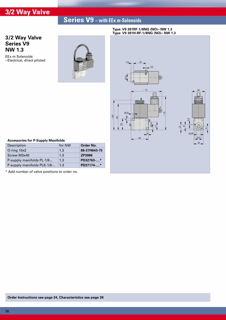
Order Instructions see page 24, Characteristics see page 28
3/2 Way ValveSeries V9 – with EEx m-Solenoids
Type: V9 381RF-1/8NG (NO)– NW 1.3Type: V9 381H-RF-1/8NG (NO)– NW 1.3
3/2 Way ValveSeries V9NW 1.3EEx m Solenoids– Electrical, direct piloted
Accessories for P-Supply Manifolds
Description for NW Order No.
O-ring 10x2 1.3 88-37H643-75
Screw M3x40 1.3 ZP3986
P-supply manifolds PL-1/8-.. 1.3 PD32763-....*
P-supply manifolds PLK-1/8-.. 1.3 PD37174-....*
* Add number of valve positions to order no.

37
2
42,5
G1/
8
15,5
40
~ 71
1
3
10
12
(1)
(3)
(10)
(12)
3,2
5,6
8
5
pst
pst
1837
69,5
5,5
M5
10,5
33,524
15,5
110
56 5
G1/
8
24,5
36
*
*
**
**16,6
30
~ 1
22
~ 1
90
G 1
/4
2247
84
52
2
1
3
52
10
12
28,5
41
4,5
30
32
M5
10
11
5,5
20
(1)
(3)
(10)
(12)
15,5
~ 71
25 pst
pst
o 4,
2
o 7,
5
G 1
/8
3044
6,5
6
6212
6
**
***
*
~ 1
37
~ 2
09
6,5
40
12
10
1
3
2
12,5
5739
117
158
68 32
G1/
2
G1/
87
21
70
~ 7573
29pst
167
~ 2
46
*
*
pst
**
**
29
70
30
5,3
9,5
1652
Dimensions in mm
3/2 Way ValveSeries S9 – with EEx m-Solenoids
Electrical pilot operationType: S9 381(S)-1/8, S9 381(S)RF-1/8
* Manual override**Only at versions with external pilot air
Versions– Normally closed– Normally open– With external pilot air
3/2 Way ValveSeries S9G1/8, G1/4, G1/2Actuation:EEx m Solenoids–Electrical pilot operation–Electrical pilot operation
with external pilot air
Note:If mounted to a P-supplymanifold, the option of spe-cifying valve S9 381S-RF-1/8as “normally open” is notavailable
Electrical pilot operationType: S9 381(S)-1/4, S9 382(S)-1/4, S9 381(S)RF-1/4
* Manual override** Only at versions with external pilot air
Electrical pilot operationType: S9 381(S)-1/2, S9 382(S)-1/2, S9 381(S)RF-1/2
* Manual override**Only at versions with external pilot air
Order Instructions see page 24, Characteristics see page 28P-Supply and RPS Manifolds see pages 41-47
Weight (mass) kg
Description Type Weight (mass)Electrical, by permanent signal S9 381(S)RF-1/8 0.247Electrical, by impulse S9 381(S)-1/8 0.382Electrical, by permanent signal S9 381(S)RF-1/4 0.500Electrical, by impulse S9 381(S)-1/4 0.600– with differential piston S9 382(S)-1/4 0.600Electrical, by permanent signal S9 381(S)RF-1/2 0.815Electrical, by impulse S9 381(S)-1/2 1.100– with differential piston S9 382(S)-1/2 1.100
only at impulse valves
only atimpulse valves
only atimpulse valves

3838
2
42,5
G1/
8
15,5
40
~ 71
1
3
12
14
3,2
5,6
8 5
pst
pst
18
55,587
,5
5,5
M5
10,5
33,524
15,5
128
56 5
G1/
8
24,5
5418
4
5
18
*
*
**
**
16,6
30
~ 1
40
~ 2
08
30
32
M5
22
G 1
/4
2222
67
106
148
52
2
4
5
1
3
15,5
52
~ 71
12
14
10
11
5,5
3029,5
41
66
6,5
6
20
62
4,5
G1/
8
pst
pst
o 4,
2
o 7,
5
25
*
*
**
**
~ 1
59
~ 2
31
6,5
14
12
5
1
3
4
2
12,5
5739
149
190
100
3232
32
G1/
2
G1/
87
21
70
~ 75
73
29pst
~ 2
01,5
~ 2
83
*
*
pst
**
**
29
70
32,5
30
5,3
9,5
4016
Order Instructions see page 24, Characteristics see page 28P-Supply and RPS Manifolds see pages 41-47
5/2 Way ValveSeries S9G1/8, G1/4, G1/2Actuation:EEx m Solenoids– Electrical pilot operation– Electrical pilot operation
with external pilot air
Versions–With external pilot air
Electrical pilot operationType: S9 581(S)-1/8, S9 581(S)RF-1/8
* Manual override** Pilot connection pst
only at type S9 381S
Electrical pilot operationType: S9 581(S)-1/4, S9 582(S)-1/4, S9 581(S)RF-1/4
Electrical pilot operationType: S9 581(S)-1/2, S9 582(S)-1/2, S9 581(S)RF-1/2
Weight (mass) kg
Description Type Weight (mass)Electrical, by permanent signal S9 581(S)RF-1/8 0.280Electrical, by impulse S9 581(S)-1/8 0.415Electrical, by permanent signal S9 581(S)RF-1/4 0.600Electrical, by impulse S9 581(S)-1/4 0.700– with differential piston S9 582(S)-1/4 0.700Electrical, by permanent signal S9 581(S)RF-1/2 1.000Electrical, by impulse S9 581(S)-1/2 1.270– with differential piston S9 582(S)-1/2 1.270
5/2 Way ValveSeries S9 – with EEx m-Solenoids
only at impulse valves
only at impulse valves
only atimpulse valves
* Manual override** Only at versions with external pilot air
* Manual override**Only at versions with external pilot air

39
2
42,5
15,5
40
~ 71
1
3
12
14
*
3,2
5,6
8 5
18
55,587
,5
5,5
M5
10,5
33,524
15,5
128
56 5
G1/
8
18
4
5
18
*
416,6
30
~ 1
40
~ 2
08
30
32
M5
22
G 1
/4
2222
67
106
148
52
2
4
5
1
3
15,5
52
~ 71
12
14
10
11
5,5
3029,5
41
66
6,5
6
20
62
4,5
G1/
8
pst
pst
o 4,
2
o 7,
5
25
*
**
**
*
~ 1
59
~ 2
31
5,3
9,5
32,5
16
6,5
40
14
12
5
1
3
4
2
5739
149
190
100
3232
32
G1/
2
7
21
70
~ 75
73
29
201,
5
~ 2
83
*
*
29
70
30
Dimensions in mm
Order Instructions see page 24, Characteristics see page 28P-Supply and RPS Manifolds see pages 41-47
5/3 Way ValveSeries S9 – with EEx m-Solenoids
Electrical pilot operationType: S9 581RF.-1/2
Electrical pilot operationType: S9 581RF.-1/8
Electrical pilot operationType: S9 581RF.-1/4
* Manual override**Only at versions with external pilot air
5/3 Way ValveSeries S9G1/8, G1/4, G1/2Actuation:EEx m Solenoids–Electrical pilot operation–Electrical pilot operation
with external pilot air
Weight (mass) kg
Description Type Weight (mass)Electrical, by permanent signal * S9 581RF.-1/8 0.247Electrical, by permanent signal * S9 581RF.-1/4 0.500Electrical, by permanent signal * S9 581RF.-1/2 0.770
*Middle position variants RFG, RFE, RFB
* Manual override* Manual override**Only at versions with external pilot air

4040
Bestellangaben siehe Seite ....., Kenngrößen siehe Seite ....Anschlußplatten siehe Seite ......., Ventilinseln siehe Seite ....
54
12
3
42
46
120
~ 1
74
~ 1
90
~ 120
*
54
12
3
54
58
140
*
~ 1
92
~ 2
08
~ 130
54
12
3
68
71
170
*
~ 2
10
~ 2
26
~ 142
5/2 and 5/3 Way Valve to ISO 5599Series S20 – with EEx m-Solenoids
Order Instructions see page 26, Characteristics see page 29Base Plates see pages 48-51
5/2 and5/3 Way ValveSeries S20to ISO 5599Sizes 1, 2, 3Actuation:EEx m Solenoids–Electrical pilot operation
5/2 and 5/3 Way Valve to ISO 5599 Size 2Type: S20 581..-2-.., S20 581RF.-2-..
5/2 and 5/3 Way Valve to ISO 5599 Size 3Type: S20 581..-3-.., S20 581RF.-3-..
Weight (mass) kg
Description Type Weight (mass)Electrical, by perm. signal S20 581RF(R)-1-.. 0.460Electrical, by impulse S20 581-1-.. 0.590Electrical, by perm. signal * S20 581RF.-1-.. 0.590Electrical, by perm. signal S20 581RF(R)-2-.. 0.700Electrical, by impulse S20 581-2-.. 0.830Electrical, by perm. signal * S20 581RF.-2-.. 0.830Electrical, by perm. signal S20 581RF(R)-3-.. 1.230Electrical, by impulse S20 581-3-.. 1.370Electrical, by perm. signal * S20 581RF.-3-.. 1.370
*Middle position variants RFG, RFE, RFB
5/2 and 5/3 Way Valve to ISO 5599 Size 1Type: S20 581..-1-.., S20 581RF.-1-..
* Manual override* Manual override
* Manual override

41
25
2010
40
30
B
13
ø6,5
4
32
86
G1/
4
21 23 23
A
11
18
109
Dimensions in mm
P-SupplyManifoldsfor Way ValveSeriesS9-1/8Versions– Type PLK-1/8
(short mounting bracket)– Type PL-1/8
(long mounting bracket)
Material
Description MaterialP-supply manifold Al, anodizedMounting bracket Steel, passivatedScrews Galvanized steelO-ring Oil-resistant rubber
P-Supply ManifoldType: PLK-1/8-..
Accessories
Description Order No.
Complete cover plate PD 34694
Flow divider PD 42483
Drawing shows: PLK-1/8-3
Dimensions, Order Instructions and Weight (mass)
Type Order No. No. of Dim. consisting of Weightvalves A B Manif. Bracket Screw O-ring (kg)
PLK-1/8-2 PD 37174-0002 2 65 79 1 2 4 2 0.28PLK-1/8-3 PD 37174-0003 3 88 102 1 2 6 3 0.31PLK-1/8-4 PD 37174-0004 4 111 125 1 2 8 4 0.34PLK-1/8-5 PD 37174-0005 5 134 148 1 2 10 5 0.37PLK-1/8-6 PD 37174-0006 6 157 171 1 2 12 6 0.40PLK-1/8-7 PD 37174-0007 7 180 194 1 2 14 7 0.43PLK-1/8-8 PD 37174-0008 8 203 217 1 2 16 8 0.47PLK-1/8-9 PD 37174-0009 9 226 240 1 2 18 9 0.50PLK-1/8-10 PD 37174-0010 10 249 263 1 2 20 10 0.53
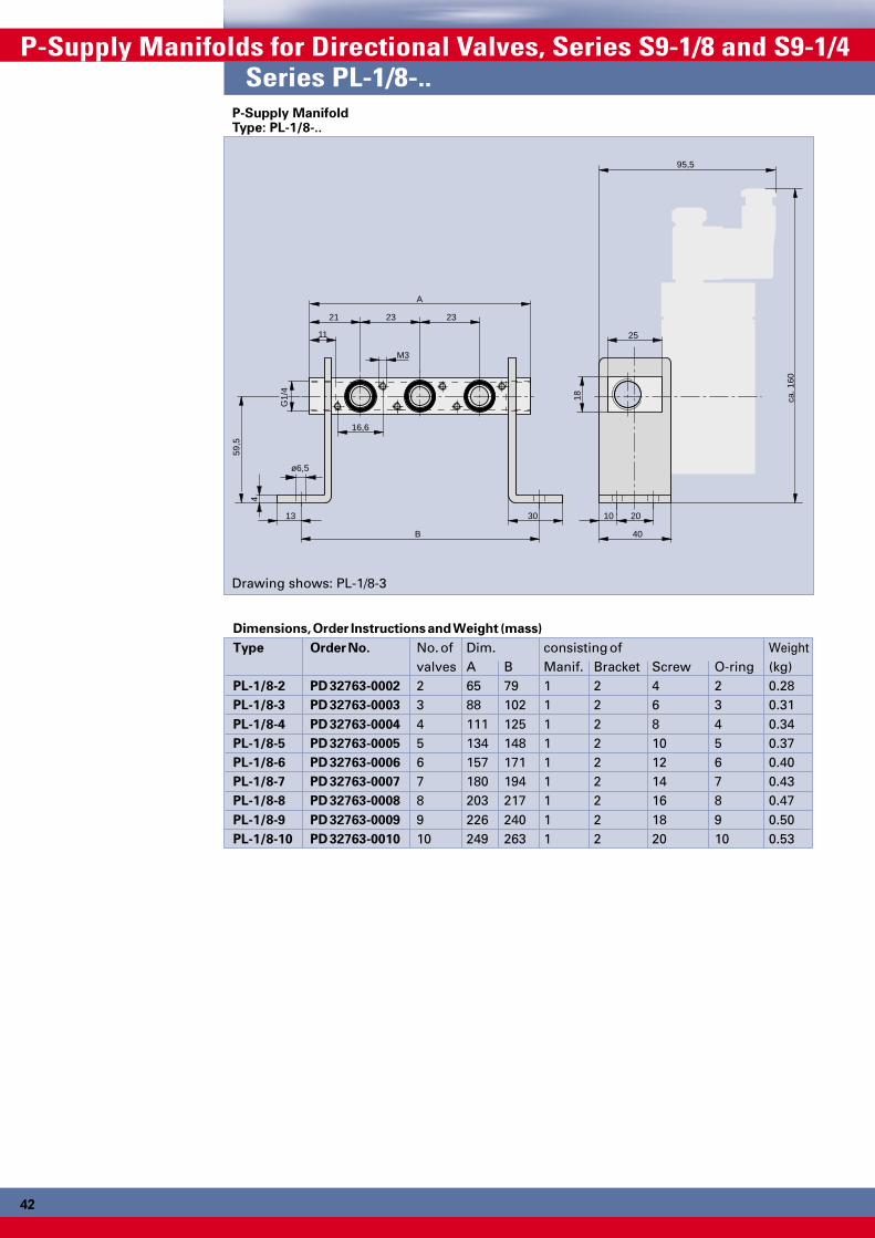
P-Supply Manifolds for Directional Valves, Series S9-1/8Series PL-1/8-..
P-supply manifolds reduceand simplify tubing.They allow a compact andclear design.3/2, 5/2 and 5/3 directionalvalves with different typesof actuation can be mountedin groups of 2-10 pieces.
The use of impulse solenoidvalves is only possiblewith P-supply manifold typePLK-..
The delivery includesP-supply manifoldMounting bracketMounting screwsO-rings
4242
2010
40
30
B
13
ø6,5
4
59,5
ca. 1
60
G1/
4
21 23 23
A
11 25
18
16,6
M3
95,5
P-Supply Manifolds for Directional Valves, Series S9-1/8 and S9-1/4Series PL-1/8-..
P-Supply ManifoldType: PL-1/8-..
Drawing shows: PL-1/8-3
Dimensions, Order Instructions and Weight (mass)
Type Order No. No. of Dim. consisting of Weightvalves A B Manif. Bracket Screw O-ring (kg)
PL-1/8-2 PD 32763-0002 2 65 79 1 2 4 2 0.28PL-1/8-3 PD 32763-0003 3 88 102 1 2 6 3 0.31PL-1/8-4 PD 32763-0004 4 111 125 1 2 8 4 0.34PL-1/8-5 PD 32763-0005 5 134 148 1 2 10 5 0.37PL-1/8-6 PD 32763-0006 6 157 171 1 2 12 6 0.40PL-1/8-7 PD 32763-0007 7 180 194 1 2 14 7 0.43PL-1/8-8 PD 32763-0008 8 203 217 1 2 16 8 0.47PL-1/8-9 PD 32763-0009 9 226 240 1 2 18 9 0.50PL-1/8-10 PD 32763-0010 10 249 263 1 2 20 10 0.53
42

43
30
2010
40
30
B
13
ø6,5
4
38
109
G3/
8
28 33 33
A
12
120
Dimensions in mm
Material
Description MaterialP-supply manifold Al, anodizedMounting bracket Steel, passivatedScrews Galvanized steelO-ring Oil-resistant rubber
Accessories
Description Order No.
Complete cover plate PD 34695
Flow divider PD 42516
P-Supply ManifoldType: PLK-1/8-..
Dimensions, Order Instructions and Weight (mass)Type Order No. No. of Dim. consisting of Weight
valves A B Manif. Bracket Screw O-ring (kg)PLK-1/4-2 PD 37175-0002 2 89 99 1 2 4 2 0.31PLK-1/4-3 PD 37175-0003 3 122 132 1 2 6 3 0.35PLK-1/4-4 PD 37175-0004 4 155 165 1 2 8 4 0.39PLK-1/4-5 PD 37175-0005 5 188 198 1 2 10 5 0.43PLK-1/4-6 PD 37175-0006 6 221 231 1 2 12 6 0.47PLK-1/4-7 PD 37175-0007 7 254 264 1 2 14 7 0.51PLK-1/4-8 PD 37175-0008 8 287 297 1 2 16 8 0.55PLK-1/4-9 PD 37175-0009 9 320 330 1 2 18 9 0.59PLK-1/4-10 PD 37175-0010 10 353 363 1 2 20 10 0.63
Series PL-1/4-..
Drawing shows: PLK-1/4-3
P-supply manifolds reduceand simplify tubing.They allow a compact andclear design.3/2, 5/2 and 5/3 directionalvalves with different typesof actuation can be mountedin groups of 2-10 pieces.
The use of impulse solenoidvalves is only possiblewith P-supply manifold typePLK-..
The delivery includesP-supply manifoldMounting bracketMounting screwsO-rings
P-SupplyManifoldsfor Way ValveSeriesS9-1/4Versions– Type PLK-1/4
(short mounting bracket)– Type PL-1/4
(long mounting bracket)

4444
2010
40
30
B
13
ø6,5
4
60
ca. 1
76
G3/
8
28 33 33
A
12 30
20
25
M4
98
P-Supply Manifolds for Directional Valves, Series S9-1/4 and S9-1/2Series PL-1/4-..
P-Supply ManifoldType: PL-1/4-..
Dimensions, Order Instructions and Weight (mass)
Type Order No. No. of Dim. consisting of Weightvalves A B Manif. Bracket Screw O-ring (kg)
PL-1/4-2 PD 32765-0002 2 89 99 1 2 4 2 0.31PL-1/4-3 PD 32765-0003 3 122 132 1 2 6 3 0.35PL-1/4-4 PD 32765-0004 4 155 165 1 2 8 4 0.39PL-1/4-5 PD 32765-0005 5 188 198 1 2 10 5 0.43PL-1/4-6 PD 32765-0006 6 221 231 1 2 12 6 0.47PL-1/4-7 PD 32765-0007 7 254 264 1 2 14 7 0.51PL-1/4-8 PD 32765-0008 8 287 297 1 2 16 8 0.55PL-1/4-9 PD 32765-0009 9 320 330 1 2 18 9 0.59PL-1/4-10 PD 32765-0010 10 353 363 1 2 20 10 0.63
Drawing shows: PL-1/4-3

45
50
6010
80
35
B
15,5
ø11
3
35
135
G3/
4
30,5 41 41
A
20
40
132
Dimensions in mm
Material
Description MaterialP-supply manifold Al, anodizedMounting bracket Steel, passivatedScrews Galvanized steelO-ring Oil-resistant rubber
Accessories
Description Order No.
Complete cover plate PD 39138
Flow divider PD 40012
P-Supply ManifoldType: PL-1/2-.
Dimensions, Order Instructions and Weight (mass)
Type Order No. No. of Dim. consisting of Weightvalves A B Manif. Bracket Screw O-ring (kg)
PL-1/2-2 PD 39016-0002 2 102 122 1 2 4 2 0.45PL-1/2-3 PD 39016-0003 3 143 163 1 2 6 3 0.60PL-1/2-4 PD 39016-0004 4 184 204 1 2 8 4 0.80
Series PL-1/2-.
P-supply manifolds reduceand simplify tubing.They allow a compact andclear design.3/2, 5/2 and 5/3 directionalvalves with different typesof actuation can be mountedin groups of 2-4 pieces.
The delivery includesP-supply manifoldMounting bracketMounting screwsO-rings
P-SupplyManifoldsfor Way ValveSeriesS9-1/2
Versions– Type PL-1/2
(short mounting bracket)
Drawing shows: PL-1/2-3

4646
B
G1/
4
20,5
5,5
A
29,5
11
49,5 23 23
65
25
12
9
43 99
5
1
3
RPS-Supply Manifold for Directional Valves, Series S9-1/8 and S9-1/4Series RPSL-1/8-..
RPS-SupplyManifoldsfor Way ValveSeriesS9-1/8
Material
Description MaterialRPS-supply manifold Al, anodizedScrews Galvanized steelO-ring Oil-resistant rubber
Accessories
Description Order No.
Complete cover strip PD 32956
Flow divider PD 42483
RPS-Supply ManifoldType: RPSL-S9-1/8-..
RPS-supply manifoldsreduce and simplify tubing.They allow a compact andclear design.The RPS manifolds have acommon compressed airsupply (P) and commonvent lines (R, S).Valves can be mounted ingroups of 2-10 pieces.
The delivery includesRPS-supply manifoldMounting screwsO-rings
Dimensions, Order Instructions and Weight (mass)
Type Order No. No. of Dimensions consisting of Weightvalves A B Manifold Screw O-ring (kg)
RPSL-S9-1/8-2 PD 44813-0002 2 122 63 1 4 6 0.47RPSL-S9-1/8-3 PD 44813-0003 3 145 86 1 6 9 0.57RPSL-S9-1/8-4 PD 44813-0004 4 168 109 1 8 12 0.67RPSL-S9-1/8-5 PD 44813-0005 5 191 1321 1 10 15 0.77RPSL-S9-1/8-6 PD 44813-0006 6 214 155 1 12 18 0.87RPSL-S9-1/8-7 PD 44813-0007 7 237 178 1 14 21 0.97RPSL-S9-1/8-8 PD 44813-0008 8 260 201 1 16 24 1.07RPSL-S9-1/8-9 PD 44813-0009 9 283 224 1 18 27 1.17RPSL-S9-1/8-10 PD 44813-0010 10 306 247 1 20 30 1.27
Drawing shows: RPSL--S9-1/8-3

47
B
G3/
8
24
6,5
A
29,5
54,5
12,5
54,5 33 33
83
31
18,5
12
50 123
5
1
3
Dimensions in mm
Material
Description MaterialRPS-supply manifold Al, anodizedScrews Galvanized steelO-ring Oil-resistant rubber
Accessories
Description Order No.
Complete cover strip PD 32957
Flow divider PD 42516
RPS-SupplyManifoldsfor Way ValveSeriesS9-1/4
RPS-supply manifoldsreduce and simplify tubing.They allow a compact andclear design.The RPS manifolds have acommon compressed airsupply (P) and commonvent lines (R, S).Valves can be mounted ingroups of 2-10 pieces.
The delivery includesRPS-supply manifoldMounting screwsO-rings
Dimensions, Order Instructions and Weight (mass)
Type Order No. No. of Dimensions consisting of Weightvalves A B Manifold Screw O-ring (kg)
RPSL-S9-1/4-2 PD 44814-0002 2 142 83 1 4 6 0.845RPSL-S9-1/4-3 PD 44814-0003 3 175 116 1 6 9 1.045RPSL-S9-1/4-4 PD 44814-0004 4 208 149 1 8 12 1.245RPSL-S9-1/4-5 PD 44814-0005 5 241 182 1 10 15 1.445RPSL-S9-1/4-6 PD 44814-0006 6 274 215 1 12 18 1.645RPSL-S9-1/4-7 PD 44814-0007 7 307 248 1 14 21 1.845RPSL-S9-1/4-8 PD 44814-0008 8 340 281 1 16 24 2.045RPSL-S9-1/4-9 PD 44814-0009 9 373 314 1 18 27 2.245RPSL-S9-1/4-10 PD 44814-0010 10 406 347 1 20 30 2.445
Series RPSL-1/4-..
Drawing shows: RPSL--S9-1/4-3

4848
F
C
B
D
E
K
L
A K
4 2 1214
5 1 3
Q
P
MH
J
N
O
B
K
5 3
1
A
F
B
G
E
D
C
L
H
J K
2
12
4
14
Q
P
C
O
N
M
Base Plates to ISO 5599 Size 1, 2, 3Single Base Plates
Single Base Plate, Form AType: S9-.-A
Dimensions Table (mm), Single Base Plate, Form A
ISO-Size A B C D E F G H1 84 43 G1/4 10.5 21.5 10 32 982 95 56 G3/8 14 26 13 40 1123 119 68 G1/2 17 17 18 32 136
ISO-Size J K L M N O P Q1 48 5.5 110 10.5 23.5 24 G1/8 582 57 6.6 124 14 30 30 G1/8 743 71 6.6 149 17 22 32 G1/8 90
Single Base Plate, Form BType: S9 -.-B
Dimensions Table (mm),Single Base Plate, Form B
ISO-Size A B C D E F H J1 46 110 10 30 5 84 G1/8 G1/42 56 124 13 35 6.5 95 G1/8 G3/83 71 149 18 32 9 119 G1/8 G1/2
ISO-Size K L M N O P Q1 5.5 98 23 46 62 23 7.52 6.6 112 28 56 73 27 7.53 6.6 136 34 68 90 35 10
Base Platesto ISO 5599Sizes 1, 2, 3
Versions– Single base plates
according toVDMA 24345 form A
– Single base platesaccording toVDMA 24345 form B
Order Instructions
ISO- Order Instructions
Size Type Order No.
1 S9-1-A KX 9076
2 S9-2-A KX 9433
3 S9-3-A KX 9434
Order Instructions
ISO- Order Instructions
Size Type Order No.
1 S9-1-B KX 9077
2 S9-2-B KX 9436
3 S9-3-B KX 9437

49
E
C
24
B
G
A
F
D
24
4
2
Dimensions in mm
Base Platesto ISO 5599Sizes 1, 2, 3
Versionsto VDMA 24345–End plate set, form D
to intermediate plate form C–Intermediate plate, form C–Plate combinations
of forms C and D–Angle base plate, form E,
for intermediate plate,form C
–Accessories
End Plate Set, Form Dfor Intermediate Plate
Order Instructions
ISO- Order Instructions
Size Type Order No.
1 S9-1-D KX 9078
2 S9-2-D KX 9421
3 S9-3-D KX 9422
ComprisesEnd plate set, completewith screws
Intermediate Plate, Form CAngle Base Plate, Form Efor Intermediate Base Plate, Form C
Dimensions Table (mm) and Order Instructions
Order Instructions ISO- A B C D E F GType Order No. SizeS9-1-E KX 9081 1 37 12 25 42 110 22 G1/4– – 2 – – – – – – –S9-3-E KX 9425 3 45 17 29 70 190 36 G1/2
ComprisesAngle base plate, complete with O-rings and screws
Intermediate Plate, Form C
ISO-Size 2
Dummy Plate
End Plate, Form D
Angle Base Plate, Form E
ISO-Size 1
Adapter Plate
ISO-Size 3
End Plate, Form D
Base Plates Combinations
Order Instructions
ISO- Order Instructions
Size Type Order No.
1 S9-1-C KX 9079
2 S9-2-C KX 9419
3 S9-3-C KX 9420
ComprisesIntermediate plate,complete with O-rings andscrews
5050
B
A
A
B
N
T
P
M L K O J
A
C
R
S
E
D1
3
5
4
2
B
14
U
C
H
V
GF
3
1
5
12
Base Plates to ISO 5599 Sizes 1, 2, 3Base Plates Combinations
Base Platesto ISO 5599Sizes 1, 2, 3
Versionsto VDMA 24345–End plate set, form D to
intermediate plate form C–Intermediate plate, form C–Plate combinations
of forms C and D–Angle base plate, form E,
for intermediate plate,form C
–Accessories
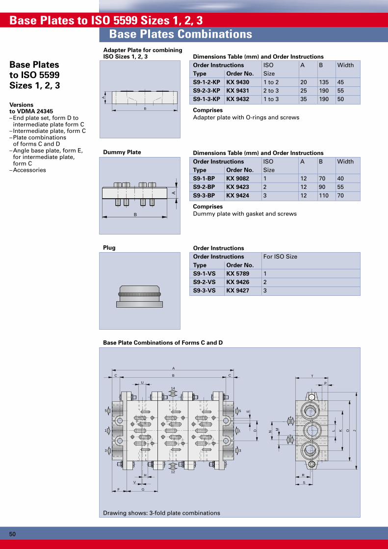
Adapter Plate for combiningISO Sizes 1, 2, 3 Dimensions Table (mm) and Order Instructions
Order Instructions ISO A B WidthType Order No. SizeS9-1-2-KP KX 9430 1 to 2 20 135 45S9-2-3-KP KX 9431 2 to 3 25 190 55S9-1-3-KP KX 9432 1 to 3 35 190 50
Comprises
Adapter plate with O-rings and screws
Dummy Plate Dimensions Table (mm) and Order Instructions
Order Instructions ISO A B WidthType Order No. SizeS9-1-BP KX 9082 1 12 70 40S9-2-BP KX 9423 2 12 90 55S9-3-BP KX 9424 3 12 110 70
Comprises
Dummy plate with gasket and screws
Plug Order Instructions
Order Instructions For ISO SizeType Order No.
S9-1-VS KX 5789 1S9-2-VS KX 9426 2S9-3-VS KX 9427 3
Base Plate Combinations of Forms C and D
Drawing shows: 3-fold plate combinations

51Dimensions in mm
Dimensions Table (mm)
ISO Number A B C D E F G H J K L M N O P R S T U VSize of Plates1 2 130 108 11 28 Ø7 22 43 7.5 110 56 G3/8 G1/4 26 85 8.5 21 24 46 G1/8 1.51 3 173 151 11 28 Ø7 22 43 7.5 110 56 G3/8 G1/4 26 85 8.5 21 24 46 G1/8 1.51 4 216 194 11 28 Ø7 22 43 7.5 110 56 G3/8 G1/4 26 85 8.5 21 24 46 G1/8 1.51 5 259 237 11 28 Ø7 22 43 7.5 110 56 G3/8 G1/4 26 85 8.5 21 24 46 G1/8 1.51 6 302 280 11 28 Ø7 22 43 7.5 110 56 G3/8 G1/4 26 85 8.5 21 24 46 G1/8 1.52 2 164 138 13 35 Ø9 26 56 6 135 68 G1/2 G3/8 30 100 9 22 24 47 G1/8 52 3 220 194 13 35 Ø9 26 56 6 135 68 G1/2 G3/8 30 100 9 22 24 47 G1/8 52 4 276 250 13 35 Ø9 26 56 6 135 68 G1/2 G3/8 30 100 9 22 24 47 G1/8 52 5 332 306 13 35 Ø9 26 56 6 135 68 G1/2 G3/8 30 100 9 22 24 47 G1/8 52 6 388 362 13 35 Ø9 26 56 6 135 68 G1/2 G3/8 30 100 9 22 24 47 G1/8 53 2 202 172 15 52 Ø12 30 71 8 190 104 G1 G1/2 38 140 10 31 34 56 G1/8 63 3 273 243 15 52 Ø12 30 71 8 190 104 G1 G1/2 38 140 10 31 34 56 G1/8 63 4 344 314 15 52 Ø12 30 71 8 190 104 G1 G1/2 38 140 10 31 34 56 G1/8 63 5 415 385 15 52 Ø12 30 71 8 190 104 G1 G1/2 38 140 10 31 34 56 G1/8 63 6 486 456 15 52 Ø12 30 71 8 190 104 G1 G1/2 38 140 10 31 34 56 G1/8 6
Order Instructions for Base Plate Combinations
Description ISO Size Order Instructions
Type Order No.
Plate combination for 2 valves 1 S9-1-002 PD 30076-0002
2 S9-2-002 PD 32951-0002
3 S9-3-002 PD 32952-0002
Plate combination for 3 valves 1 S9-1-003 PD 30076-0003
2 S9-2-003 PD 32951-0003
3 S9-3-003 PD 32952-0003
Plate combination for 4 valves 1 S9-1-004 PD 30076-0004
2 S9-2-004 PD 32951-0004
3 S9-3-004 PD 32952-0004
Plate combination for 5 valves 1 S9-1-005 PD 30076-0005
2 S9-2-005 PD 32951-0005
3 S9-3-005 PD 32952-0005
Plate combination for 6 valves 1 S9-1-006 PD 30076-0006
2 S9-2-006 PD 32951-0006
3 S9-3-006 PD 32952-0006
Plate combinations made up to customer‘s requirements on request
AccessoriesAdapter plate for pressure switch * 1 S9-1-DR KX 9293
2 S9-2-DR KX 94283 S9-3-DR KX 9429
Adapter plate with 1 S9-1-RE PD 31826built-in pressure regulator 3 S9-3-RE PD 33098
* Pressure switches available on request

5252
Intrinsically safe field bus interfaces
Manufacturer Voltage variants
M (6–9VDC) N (7–16VDC) L (12–24VDC) E (24–30VDC)
Pepperl+Fuchs Profibus-PA: ASI:KFD2-GT(2)-DP(R).xPA VAA-2EA-G5-NV1-Ex
Turck Profibus PA SensoplexExCom ExCom ExCom
Bartec(for Profibus-DP) 07-7331-2305/0000 07-7331-2305/1000(for Interbus-S) 07-7331-2105/0000 07-7331-2105/1000
Electrically isolated Valve Control (Zener barrir)
Manufacturer Voltage variants
M (6–9VDC) N (7–16VDC) L (12–24VDC) E (24–30VDC)
STAHL 9351/10-11-10 9351/10-11-10 9351/10-12-10 9351/10-15-10(built-on types) 9351/10-12-10 9351/10-13-10 9351/10-16-10
9351/10-13-10 9351/10-14-109351/10-15-10
STAHL 9651/40-12-10 9651/40-14-10 9651/40-16-10(Europa cards) 9651/40-19-10STAHL 9151/10-11-10 9151/10-16-10(module)Pepperl+Fuchs KHD2SRÜ-Ex1.W.LB KFD2-SD-Ex1.17 KFD2-SD-Ex1.36(valve control modules) KFD2-SD-Ex1.48
KFD2-SL-Ex1.48KSD2-BO-ExEGA-041 und ...-3
Turck MK72-S01-Ex MK72-S01-Ex MK72-S02-Ex(multimodul) MK72-S03-Ex
MK72-S04-Ex MK72-S04-ExMK72-S05-ExMK72-S06-ExMK72-S07-Ex
Turck MC72-41Ex-T/24VDC MC72-41Ex-T/24VDC MC72-42Ex-T/24VDC(multicart) MC72-43Ex-T MC72-43Ex-T MC72-44Ex-TTurck MS13-231Ex0-T/24VDC(multisafe)Bartec 07-7311-93MT/AAA0
Compatibility tablesfor HOERBIGER-ORIGA Ex safety valves
?

53
Safety barriers (Zener barriers)
Manufacturer Voltage variants
M (6–9VDC) N (7–16VDC) L (12–24VDC) E (24–30VDC)
Pepperl+Fuchs Z 757 Z 710 Z 715 Z728Z710.CL Z 715.CL Z728.CLZ 715 Z 715.1K Z778Z 715.CL Z 722 Z796Z 715.1K Z 722.CL Z787Z 764 Z 765 Z787.HZ 765 Z772
Stahl 9001/01-083-442-10 9001/01-158-150-10 9004/01-168-050-10 9004/51-206-050-00
9001/01-086-390-10 9001/01-158-390-10 9001/01-199-390-10 9004/01-280-050-00
9001/01-086-150-10 9001/01-199-150-10 9004/01-315-025-00
9001/01-086-050-10 9001/01-199-100-10 9001/01-280-165-10
9001/01-199-000-10 9001/01-280-100-10
9001/01-280-085-10
9001/01-280-050-10
9001/01-280-000-10
9002/11-260-138-00
9002/13-280-093-00
9002/13-280-110-00
9002/33-280-000-00
Weidmüller Serie WIS1200
Bartec 07-7311-93M8/Q010

5454

55

A HOERBIGER-ORIGA Pneumatik GmbH • Dr. Alexander-Schärf-Straße 12 • A-2700 Wiener Neustadt • Tel. +43 (0)2622 26071-0 • Fax +43 (0)2622 26071-5 • e-mail: [email protected] HOERBIGER AUSTRALIA PTY.LTD. • 142 Lawrence • AUS-NSW2015 Alexandria (Sydney) • Tel. +61 (0)2 9550-1077 • Fax +61 (0)2 9550-6515 • e-mail: [email protected] HOERBIGER-ORIGA AG • Industriestr. 30 • CH-8112 Otelfingen (Zürich) • Tel. +41 (0)1 846 6860 • Fax +41 (0)1 846 6870 • e-mail: [email protected] HOERBIGER Compressor Valve (Shanghai) Co., Ltd. • 39 He Fa Rd, Caohejing Hi-Tech Park • ROC-200233 Shanghai • Tel. +86 (0)21 6485 0855 • Fax +86 (0)21 6485 0958 • e-mail: [email protected] HOERBIGER-ORIGA GmbH • Industriestr. 8 • D-70794 Filderstadt • Tel. +49 (0)7158 1703-0 • Fax +49 (0)7158 64870 • e-mail: [email protected] HOERBIGER-ORIGA GmbH • Südliche Römerstraße 15 • D-86972 Altenstadt • Tel. +49 (0)8861 221-0 • Fax +49 (0)8861 221-1305 • e-mail: [email protected] HOERBIGER-ORIGA GmbH (Interface) • Diessener Straße 8 • D-86956 Schongau • Tel. +49 (0)8861 2301-0 • Fax +49 (0)8861 2301-10 • e-mail [email protected] HOERBIGER-ORIGA S.A. • C/Nogal N° 8, Poig. Ind. El Nogal • E-28110 Algete (Madrid) • Tel. +349 (0)1 629 09 00 • Fax +349 (0)1 628 25 54 • [email protected] HOERBIGER-ORIGA S.A. • 11 avenue de Norvège • F-91978 Courtaboeuf • Tel.+33 (0)1 69 29 22 00 • Fax +33 (0)1 69 29 22 10 • e-mail: [email protected] HOERBIGER-ORIGA Ltd. • Tewkesbury Industrial Estate • Tewkesbury GL 20 8 ND GB • Tel. +44 1684 85 00 00 • Fax +44 1684 85 05 55 • e-mail: [email protected] HOERBIGER-ORIGA S.R.L. • Via Martiri della Libertà 4/6 • I-20060 Liscate (MI) • Tel. +39 02 95 35 03 07 • Fax +39 02 95 35 05 13J HOERBIGER NIPPON SERVICE • 129-1, Aza Houma-Kanahori-Mae • J-289-1600 Chiba-Ken • Tel. +81 (0)479 77 22 28 • Fax +81 (0)479 77 23 03NO HOERBIGER-ORIGA AS • Grønland 57 • NO-3045 Drammen • Tel. +47 3 288 08 40 • Fax +47 32 82 83 20 • e-mail: [email protected] HOERBIGER-ORIGA GmbH • Industriestr. 8 • D-70794 Filderstadt • Tel. +49 (0)7158 1703-0 • Fax +49 (0)7158 64870 • e-mail: [email protected] HOERBIGER-ORIGA Sdn Bhd • 12 Jalan USJ 7/3A Subang Jaya • MY 47610 Petaling Jaya (Selangor) • Tel. +60 (0)3 734 78 22 • Fax +60 (0)3 734 78 23 • e-mail: [email protected] HOERBIGER-ORIGA S.A. • Rua das Dozes Casas 235, 2° Dto. • P-4000 Porto • Tel. +351 22 550 71 79 • Fax. +351 22 509 22 51 • e-mail: [email protected] HOERBIGER-ORIGA Pte Ltd • 5012 ’05-01 Ang Mo Kio Ave 5, Techplace II • SGP-569876 Singapore • Tel. +65 483 2959 • Fax +65 483 29 79SE HOERBIGER-ORIGA AB • Kungsgatan 10, Box 67 • SE-73622 Kungsör • Tel. +46 227 411 00 • Fax +46 227 411 29 • e-mail: [email protected] HOERBIGER-ORIGA Corporation • 100 West Lake Drive • IL-Glendale Heights, Illinois • Tel. +1 630 871 830-0 • Fax +1 630 871 1515 • e-mail: [email protected] HOERBIGER-ORIGA (SA) (PTY) Ltd • 9 Fuchs Street • ZA-1450 Alrode, Gauteng • Tel. +27 (0)11 908 13 10 • Fax +27 (0)11 908 13 12 • e-mail: [email protected] HOERBIGER-ORIGA (SA) (PTY) Ltd • 2 Le Mans Place • ZA3608 Westmead, Pinetown • Tel. +27 (0)31 700 56 11 • Fax +27 (0)31 700 59 06 • e-mail: [email protected] HOERBIGER-ORIGA (SA) (PTY) Ltd • 4A Acteon Road • ZA-Paarden Eiland, Cape Town • Tel. +27 (0)21 511 19 05 • Fax +27 (0)21 510 29 47 • e-mail: [email protected]
A3P162E61JAB00X
HOERBIGER-ORIGA...your competent partner
with global service and distribution
for more information visit the following web siteswww. hoerbiger-origa.comwww.interact-system.comwww.airfit.comwww. hoerbiger.comor contact your local HOERBIGER-ORIGA company
The Strategic Business Units of the HOERBIGER Group
SBU AutomationTechnology
SBU DriveTechnology
Additional representatives can be found on the Internet
Your Contact
A3P162E-October 2001
SBU CompressionTechnology
The
righ
t to
intr
oduc
e te
chni
cal
mod
ifica
tions
is r
eser
ved

Electronically controlledPressure Regulating Valves
AIRFIT CONTROL

AIRFIT TECNO:SPEED, ACCURACY AND DYNAMICS IN A MINIATURE FORMAT
The airfit tecno proportional pressure regulator combines Piezo technology, precision engineering and electronics in ahighly compact arrangement, resulting in outstanding regulation speed and accuracy. To illustrate the unit’s fastresponse, less than 7 milliseconds are required from the command to change pressure until the changing pressure isregistered at the outlet. The dynamic characteristics are outstanding: with small air volumes the airfit tecno achieves alimiting frequency of 43 Hz, i.e. 43 pressure changes per second.
Reduced to the MaximumDespite its maximised performance capabilities, the minimised dimensions and weight of the airfit tecno are remarkable.The exclusive use of proportional components - instead of switching valves - contributes to an unusually long servicelife. For users who want to install the airfit tecno in their own control circuits the unit is also available in an OEM version,i.e. without the electronic regulation system.
airfit tecno
2

1
2 2 2 2 2
1 1 1 1 12 2 2 2 2
C36
7,5 E
D16
20
A
5
97
24,5
14
25
40
M3
U
P
-
36
65
ca.1
03
44
37
2
16
G1/8
1
ca. 45
4,5
15
ca.3
2
30
25
5
3
65
ca.7
3
44
37
2
*
16 36
G1/8
1
4,5
15
ca.3
2
30
25
5
3
32 20
7
25
14
15
4,5
M3
24,5
G1/8
G1/8
16
7,5
7,5
Dimensions (mm)Single Base Plate G1/8
3 (R) exhaust2 (A) outlet1 (P) compressed air supply
Dimensions (mm), Type: tecnoVersion with socket to DIN 43650-1 C and base plate for unitswith actual value output or EMC ground
Socket with 90° mounting
Dimensions (mm), Type: tecnoVersion with 3-pin plug and base plate
* Connection for 3-pin socket M8 (KC3104, KC3106)
Dimensions (mm)Manifold Base Plate G1/8
8,51
2
4,5
ø4,
5
ø7,
5
7,5
16
Design and FunctionType airfit tecno
airfit tecno uses the provenHOERBIGER-ORIGA Piezo valve asits pilot unit. In its proportionalversion this Piezo valve provides theregulator’s ‚main stage‘ with a fastand highly dynamic pilot signal. Airsupply to the Piezo valve is via anintegrated miniature pressureregulator and fine filter.For the main stage a proportionaldiaphragm pressure regulator isused, with two separate seats forpressurising and venting. The outletpressure is compared with the setpressure via a pressure sensor andis constantly corrected by theelectronic control system.
3
3
2
1
40 x no. of valves - 8

ORDER INSTRUCTIONS, TECNO
VERSION TYPE ORDER NO.
COMPLETE SETS (0-8 BAR) CONSISTING OF
Prop. pressure regulator, 0–8 V,base plate G1/8, cable set straight (2 m) PRE-U-01 PS11140-B-01
Prop. pressure regulator, 0–8 V,base plate G1/8, cable set angled (2 m) PRE-U-01 PS11150-B-01
Prop. pressure regulator, 4–20 mA,base plate G1/8, cable set straight (2 m) PRE-I-01 PS11141-B-01
Prop. pressure regulator, 4–20 mA,base plate G1/8, cable set angled (2 m) PRE-I-01 PS11151-B-01
PROP. PRESSURE REGULATORS NW 2 (SINGLE UNITS WITHOUT ACCESSORIES)
Prop. pressure regulator, 0–8 V, 0–8 bar PRE-U PS11110-B
Prop. pressure regulator, 4–20 mA, 0–8 bar PRE-I PS11111-B
Prop. pressure regulator, 0–10 V, 0–2 bar PRE-U PS11130-B-20
Prop. pressure regulator, 4–20 mA, 0–2 bar PRE-I PS11139-B-20
Prop. pressure regulator, 0–10 V, 0–200 mbar PRE-U PS11130-B-02
Prop. pressure regulator, 4–20 mA, 0–200 mbar PRE-I PS11139-B-02
ACCESSORIES
Single base plate G1/8 PS11112-A-01
Manifold base plate, 2-fold G1/8 PS11112-A-02
Manifold base plate, 4-fold G1/8 PS11112-A-04
Manifold base plate, 6-fold G1/8 PS11112-A-06
Blind plate complete PS11160-A
Cable set straight (5 m) KC3104
Cable set angled (5 m) KC3106
PROP. PRESSURE REGULATORS NW 2, WITH ACTUAL VALUE OUTPUT ANDSOCKET TO DIN 43650-1C (SINGLE UNITS WITHOUT ACCESSORIES) *
Prop. pressure regulator, 0–8 V, 0–8 bar, PRE-U PS11113-Bactual value output 1.25 V (0 bar)-6.25 V (8 bar)
Prop. pressure regulator, 0–10 V, 0–2 bar, PRE-U PS11162-B-20actual value output 1.25 V (0 bar)–6.25 V (2 bar)
Prop. pressure regulator, 0–10 V, 0–0.2 bar, PRE-U PS11162-B-02actual value output 1.25 V (0 bar)–6.25 V (0.2 bar)
PROP. PRESSURE REGULATORS NW 2, WITH EMC MASS ANDSOCKET TO DIN 43650-1C (SINGLE UNITS WITHOUT ACCESSORIES) *
Prop. pressure regulator, 0–8 V, 0–8 bar PRE-U PS11164-B
Prop. pressure regulator, 0–10 V, 0–2 bar PRE-U PS11165-B-20
Prop. pressure regulator, 0–10 V, 0–0.2 bar PRE-U PS11165-B-02
Prop. pressure regulator, 4–20 mA, 0–8 bar PRE-I PS11168-B
Prop. pressure regulator, 4–20 mA, 0–2 bar PRE-I PS11169-B-20
Prop. pressure regulator, 4–20 mA, 0–0.2 bar PRE-I PS11169-B-02
* cable KC3104 or KC3106 is not required
PARAMETERS TO VDI 3292
Mounting Flange
Port size NW 2 without base plateG1/8 with base plate
Installation In any position
Weight (mass) kg 0.145 without base plate0.180 with base plate
Flow direction On: from 1 to 2Off: from 2 to 3
Medium and ambient Tmin °C 0temperature range Tmax °C + 50
Medium Dry, filtered air (5 µm)
Lubrication None, or sparing oil mist lubrication(max. 30 mg/m3)
PNEUMATIC PARAMETERS PRESSURES ARE GAUGE PRESSURES
Input pressure range p1 min bar 1.5p1 max bar 10
Output pressure range p2 min bar 0** 0 0p2 max bar 8 2 0.2
Nominal flow rate Qn l/min 210
Max. flow rate* Qmax l/min 350
Hysteresis p2max % < 0.2 < 0.2 < 0.5
Repeatability p2max % < 0.2 < 0.2 < 0.5
Responsiveness p2max % < 0.1 < 0.1 < 0.5
Linearity p2 max % < 0.5 < 0.5 < 1
ELECTRICAL PARAMETERS
Nominal voltage UN V DC 24 = ± 10 %
Nominal power PN W 0.25
Residual ripple % 10
Power consumption*** IB max mA 10
Set value input W Type: PRE-U Type: PRE-I
Version 0–8 bar 0 V ’ 0 bar 4 mA ’ 0 bar8 V ’ 8 bar 20 mA ’ 8 bar
Version 0–2 bar 0 V ’ 0 bar 4 mA ’ 0 bar10 V ’ 2 bar 20 mA ’ 2 bar
Version 0–0.2 bar 0 V ’ 0 bar 4 mA ’ 0 bar10 V ’ 0.2 bar 20 mA ’ 0.2 bar
Input resistance RE kΩ 61.5 with 0–10 V actuationΩ 550 with 4–20 mA actuation
Protection system IP IP52 to DIN 45322
Connection 3-pin socket M8 orto DIN 43650-1 C
* at p1 = 10 bar and p2 = 6.3 bar, ∆p = 1 bar** other pressure ranges on request*** 0-10 V version
4
For detailed technical data please see Data Sheet 5.96.002
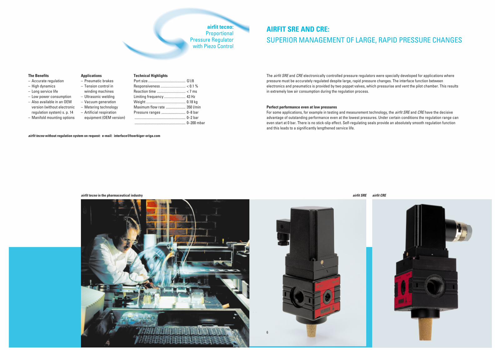
airfit tecno:Proportional
Pressure Regulatorwith Piezo Control
The Benefits– Accurate regulation– High dynamics– Long service life– Low power consumption– Also available in an OEM
version (without electronicregulation system) s. p. 14
– Manifold mounting options
Technical HighlightsPort size .......................................... G1/8Responsiveness ............................ < 0.1 %Reaction time ................................ < 7 msLimiting frequency ........................ 43 HzWeight ............................................ 0.18 kgMaximum flow rate ...................... 350 l/minPressure ranges ........................... 0–8 bar......................................................... 0–2 bar......................................................... 0–200 mbar
Applications– Pneumatic brakes– Tension control in
winding machines– Ultrasonic welding– Vacuum generation– Metering technology– Artificial respiration
equipment (OEM version)
airfit tecno in the pharmaceutical industry
airfit tecno without regulation system on request: e-mail: [email protected]
5
AIRFIT SRE AND CRE:SUPERIOR MANAGEMENT OF LARGE, RAPID PRESSURE CHANGES
The airfit SRE and CRE electronically controlled pressure regulators were specially developed for applications wherepressure must be accurately regulated despite large, rapid pressure changes. The interface function betweenelectronics and pneumatics is provided by two poppet valves, which pressurise and vent the pilot chamber. This resultsin extremely low air consumption during the regulation process.
Perfect performance even at low pressuresFor some applications, for example in testing and measurement technology, the airfit SRE and CRE have the decisiveadvantage of outstanding performance even at the lowest pressures. Under certain conditions the regulation range caneven start at 0 bar. There is no stick-slip effect. Self-regulating seals provide an absolutely smooth regulation functionand this leads to a significantly lengthened service life.
airfit CREairfit SRE
6

62
56
4
5,5
22
46
ø37
58,5
65
48
62
20
3727
37
174
44,8
52,5
50
5
23
4,5
ø37
56
50
35
23
31,5
22,5
45
152,
5
45
50,5
1
24 3
+ +
–
0 V24 V DC
U
1 Vbar
0 – 10 V
Analogue Voltage PLC Combined with Several Potentiometers
1
24 3
+ +
–
0 V24 V DC
U
1 Vbar
0 – 10 V
1
24 3
+ +
–
0 V24 V DC
U
1 Vbar
0 – 10 V
SPS
With Single Potentiometer
Resistance of potentiometer should bebetween 500 Ω and 100 kΩ
Total resistance of potentiometer seriesshould be not less than 500 Ω
Control Possibilities
Dimensions (mm) Type: CRE-1/2
Design and FunctionType SRE and CRE
Two poppet valves convertelectrical impulses into the pilotpressure. This positivepressurisation of the pilot chambereliminates permanent airconsumption. Air consumptionduring the regulation process isextremely low.The main stage is a piston-typepressure regulator.The self-regulating seal betweenthe pilot chamber and the outlet p2prevents the so-called stick-slipeffect and thus lengthens theservice life of the regulator.The airfit SRE and CRE can becontrolled by a PLC or apotentiometer, optionally with0–10 V, 0–20 mA or 4–20 mA. A fastexhaust system is built into the airfitSRE and CRE.
7
Dimensions (mm) Type: MRE-M5 Dimensions (mm) Type: SRE-1/4
Other connectorson request
Integratedelectronicregulationsystem
Pilot valve
Compressedair supply
Exhaust
Outlet

ORDER INSTRUCTIONS FOR MRE, SRE, CRE
BASIC VERSION FOR 0–10 V CONTROL, NG (NORMALLY CLOSED)
PORT SIZE MAX. OUTPUT TYPE ORDER NO.PRESSURE (BAR)
M5 10 MRE-U-M5 NG PB60349-000
G1/4 10 SRE-U-1/4 NG PB59849-000
G3/8 10 SRE-U-3/8 NG PB59949-000
G3/8 10 CRE-U-3/8 NG PB60149-000
G1/2 10 CRE-U-1/2 NG PB60249-000
VERSION FOR 4–20 mA CONTROL
M5 10 SRE-I-M5 NG PB60349-002
G1/4 10 SRE-I-1/4 NG PB59849-002
G3/8 10 SRE-I-3/8 NG PB59949-002
G3/8 10 CRE-I-3/8 NG PB60149-002
G1/2 10 CRE-I-1/2 NG PB60249-002
VERSION FOR 0–20 mA CONTROL
M5 10 SRE-M5 NG PB60349-001
G1/4 10 SRE-I-1/4 NG PB59849-001
G3/8 10 SRE-I-3/8 NG PB59949-001
G3/8 10 CRE-I-3/8 NG PB60149-001
G1/2 10 CRE-I-1/2 NG PB60249-001
VERSION FOR 0–10 V CONTROL, NO (NORMALLY OPEN)
M5 10 SRE-U-M5 NO PB60349-010
G1/4 10 SRE-U-1/4 NO PB59849-010
G3/8 10 SRE-U-3/8 NO PB59949-010
G3/8 10 CRE-U-3/8 NO PB60149-010
G1/2 10 CRE-U-1/2 NO PB60249-010
ACCESSORIES
Mounting kit SRE PL16965
Mounting kit CRE PL17518
Coupling kit SRE PL16959
Coupling kit CRE PL17608
Adapter plate kit G3/4 for CRE PL17682
PARAMETERS TO VDI 3292
MRE SRE CRE
Port size M5 G1/4 G3/8 G3/8 G1/2
Installation In any position
Weight (mass) kg 0.3 0.6 0.95
Medium and ambient Tmin °C 0temperature range Tmax °C + 50
Medium Filtered, lubricated orunlubricated compressed air
Lubrication Not required
PNEUMATIC PARAMETERS PRESSURES ARE GAUGE PRESSURES
Nominal pressure pn bar 6.3
Inlet pressure range p1 min bar 0 0p1 max bar 10 16
Outlet pressure range p2 min bar 0**p2 max bar 10
Maximum flow rate* Qmax l/min 10 2200 2500 7000 7500
Hysteresis p2 max % < 1
Repeatability p2 max % < 0.5
Responsiveness p2 max % < 0.5
Linearity p2 max % < 1
ELECTRICAL PARAMETERS
Nominal voltage UN V DC 24 V = ± 10 %
Residual ripple % 10
Power consumption IB max A 0.15
Set value - input UW V 0–10I mA 0–20, 4–20
Input resistance RE kΩ 200
Actual value - output UX V 0–10
Output current IA max mA 20
Protection system IP IP65 toDIN 40050,EN 60529
* at p1 = 10 bar and p2 = 6.3 bar, ∆p = 1 bar** if p1 > 1.2 bar
For detailed technical data please see Data Sheets 5.96.004 and 5.96.005
8

airfit SRE and CRE:Proportional Pressure
Regulators withPoppet-Valve Pilot Control
The Benefits– No permanent
air consumption– Accurate pressure
regulation– High dynamics– High connection flexibility
(electrical and pneumatic)– High flow rates in both
directions– Long service life
Applications– Welding robots– Erosion machines– Assembly/nut tightening
operations– Testing and measurement
technology(liquids and gases)
– Conveyor belt positioning– Grinding and polishing
machines
airfit SRE and CRE in the automotive industry
Technical Highlights airfit SRE airfit CREPort sizes ........................................ G1/4, G3/8 ......... G3/8, G1/2Maximum flow rate ...................... 2500 l/min ......... 7500 l/minProtective system ......................... IP 65 .................. IP 65Responsiveness ............................ < 0.5 % .............. < 0.5 %Input pressures ............................. 0–10 bar ........... 0–16 barActual value output ...................... standard ........... standardAllocation ....................................... 1 V ^ 1 bar ........ 1 V ^1 bar= =
9

AIRFIT SRT AND CRT:THE COMBINATION OF POWER AND SPEED
The airfit SRT and CRT electronically controlled pressure regulators are especially recommended for applications thatdemand extremely fast pressure changes at high flow rates. The combination of airfit tecno as the pilot valve and airfitSRE or CRE as the pneumatic amplifier provides a unique solution for such a requirements profile.
airfit CRTairfit SRT
10

PARAMETERS TO VDI 3292
GENERAL
System Piston-type pressure regulator with Piezo pilot control, without
electrical feedback
Type SRT CRT
Port size G1/4 G1/2
Installation In any position
Weight (mass) kg 0.8 1.15
Medium and ambient Tmin °C 0temperature range Tmax °C 50
Medium Dried and filtered air (5 µ), with orwithout sparing oil mist
lubrication (max. 30 mg/m3)
PNEUMATIC PARAMETERS PRESSURES ARE GAUGE PRESSURES
Nominal pressure pn bar 6.3
Inlet pressure range p1 min bar 1.5p1 max bar 10
Outlet pressure range p2 min bar 0p2 max bar 8
Maximum flow rate* Qmax l/min 2000 7500
Hysteresis p2max % < 5 < 15
Repeatability p2 max % < 1 < 2
Responsiveness p2 max % < 5 < 15
Linearity p2max % < 1 < 2
Reaction time t1 ms < 16 < 19
ELECTRICAL PARAMETERS
Nominal Voltage UN V DC 24 V ± 10 %
Nominal power rating PN W 0.25
Set value input 0–8 V4–20 mA
Input resistance RE kΩ 61.5 with 0-10 V controlΩ 550 with 4-20 mA control
Protection system IP52 to DIN 45322
Connection 3-pin socket M8or to DIN 43650-1C
DYNAMIC PARAMETERS
Pressure build-up from t ms < 1000 to 6 bar atflow rate of 500 l/min
Pressure build-up from t ms < 503 to 6 bar with avolume of 1.3 l
* at p1 = 10 bar and p2 = 6.3 bar, ∆p = 1 bar
Design and FunctionType airfit SRT and CRT
The airfit tecno is used as the pilotcontrol in the airfit SRT and CRTpressure regulators and contributessignificantly to the highly dynamicperformance capabilities. The mainstage uses the airfit SRE or CREpiston-type pressure regulator.The unit does not have a closedcontrol circuit, i.e. there is nofeedback of the output pressuresignal.
ORDER INSTRUCTIONS FOR SRT, CRT
VERSION TYPE ORDER NO.
PROP. PRESSURE REGULATOR G1/4
Prop. pressure regulator, 0–8 V, 0–8 bar SRT-U-1/4 PS11230-A
Prop. pressure regulator, 4–20 mA, 0–8 bar SRT-I-1/4 PS11231-A
PROP. PRESSURE REGULATOR G1/2
Prop. pressure regulator, 0–8 V, 0–8 bar CRT-U-1/2 PS11240-A
Prop. pressure regulator, 4–20 mA, 0–8 bar CRT-I-1/2 PS11241-A
ACCESSORIES
Mounting kit SRT-1/4 PL16965
Mounting kit CRT-1/2 PL17518
Cable set straight (5 m) KC3104
Cable set angled (5 m) KC3106
11 12
For detailed technical data please see Data Sheet 5.96.006.
Dimensions (mm) Type: CTR-1/2
Dimensions (mm) Type: SRT-1/4
-

The Benefits– Extremely fast pressure
changes– Long service life– Low power consumption
(0.25 W)
Technical Data airfit SRT airfit CRTPort sizes ........................................ G1/4 ................... G1/2Weight ............................................ 0.8 kg ................. 1.15 kgPressure range ............................. 0–8 bar .............. 0–8 barMaximum flow rate ...................... 2200 l/min .......... 7500 l/minResponsiveness ............................ < 5 %.................. < 15 %Reaction time ................................ < 15 ms .............. < 15 ms
Applications– Welding robots– Paint spraying equipment
airfit SRT and CRT in painting technology
13
airfit SRT and CRT:Pressure Regulators
with Piezo Pilot Controland Piston-Type
Regulator Main Stage
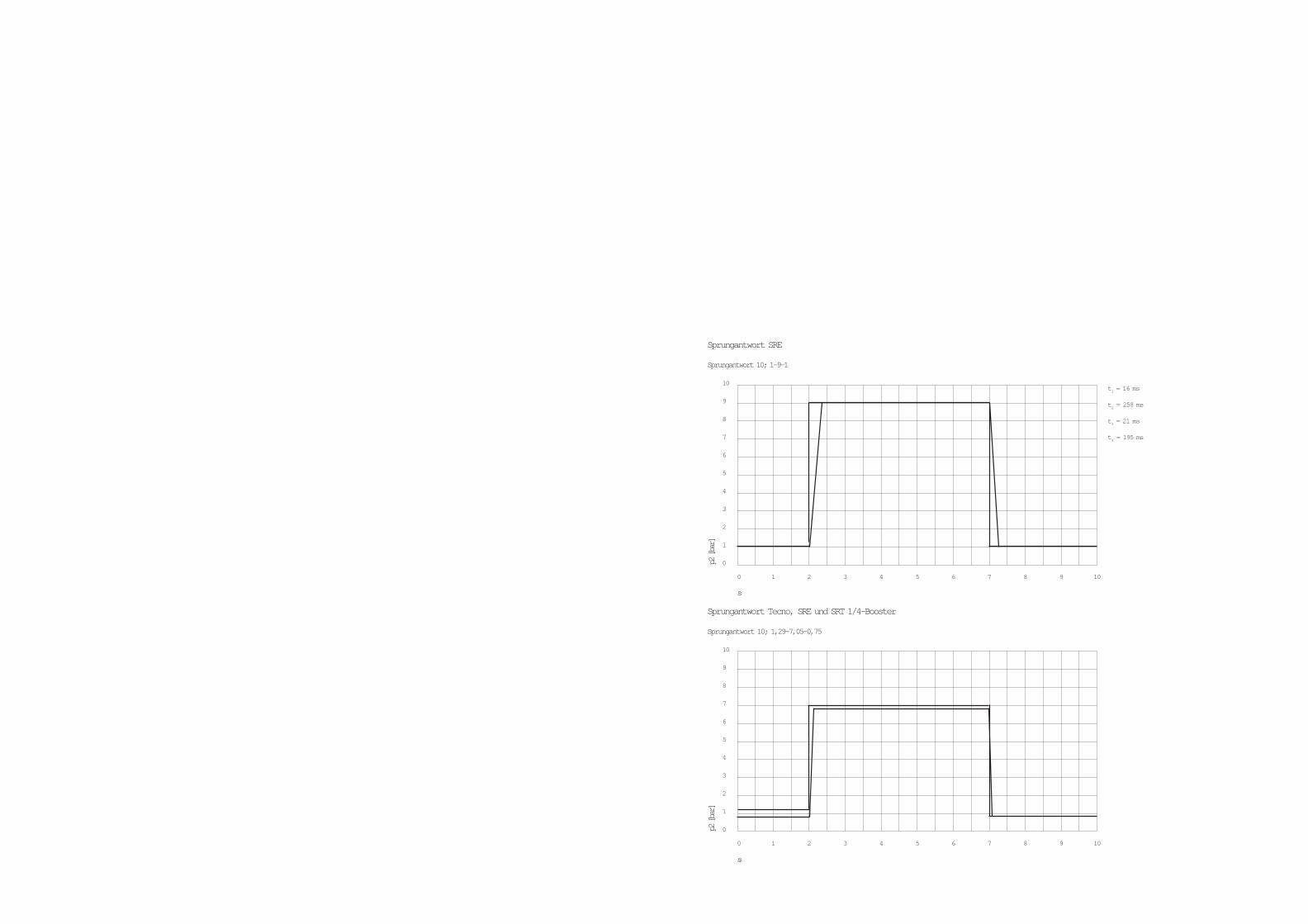
s
0 1 2 3 4 5 6 7 8 9 10
p2 [b
ar]
10
9
8
7
6
5
4
3
2
1
0
Sprungantwort Tecno, SRE und SRT 1/4-Booster
Sprungantwort 10; 1,29-7,05-0,75
t1 = 16 ms
t2 = 258 ms
t3 = 21 ms
t4 = 195 ms
s
0 1 2 3 4 5 6 7 8 9 10
p2 [b
ar]
10
9
8
7
6
5
4
3
2
1
0
Sprungantwort SRE
Sprungantwort 10; 1-9-1

AIRFIT CONTROL:MAKING THE RIGHT CHOICE
With airfit control, HOERBIGER-ORIGA offers a pressure regulator programme that delivers the right solution for every application.This table will make it easier for you to select the optimum regulator for your specific application.
airfit control:in Overview
Flow CharacteristicsSRE-1/4
Flow CharacteristicsCRT-1/2
Flow CharacteristicsTecno
90 %
10 %
t1
t2
t3
t4
OffOnChange Response Diagram
UNITS WITH CLOSED LOOP WITHOUT CLOSED LOOP
Type TECNO MRE-M5 SRE-1/4 SRE-3/8 CRE-3/8 CRE-1/2 SRT-1/4 CRT-1/2
System Diaphragm- Pulsed 2/2 way Piston-type pressure regulator Piston-type pressure regulator Piston-type pressure regulatortype pressure electronic with electromagnetic with electromagnetic with Tecno pilot controlregulator with valves, pilot control pilot controlPiezo pilot electronicallycontrol regulated
Port size G1/8 M5 G1/4 G3/8 G3/8 G1/2 G1/4 G1/2
Inlet pressure 1.5–10 bar 0–10 bar 0–10 bar 0–10 bar 0–16 bar 0–16 bar 1.5–10 bar 1.5–10 bar
Outlet pressure 0–8 bar 0–10 bar 0–10 bar 0–10 bar 0–10 bar 0–10 bar 0–8 bar 0–8 bar0–2 bar0–0.2 bar*
Qmax [l/min] 350 10 2200 2500 7000 7500 2000 7500
Hysteresis < 0.2 % (< 0.5 %)* < 1 % < 1 % < 1 % < 1 % < 1 % < 5 % < 15 %
Repeatability < 0.2 % (< 0.5 %)* < 0.5 % < 0.5 % < 0.5 % < 0.5 % < 0.5 % < 1 % < 2 %
Responsiveness < 0.1 % (< 0.5 %)* < 0.5 % < 0.5 % < 0.5 % < 0.5 % < 0.5 % < 5 % < 15 %
Linearity < 0.5 % (< 1 %)* < 1 % < 1 % < 1 % < 1 % < 1 % < 1 % < 2 %
Set value input 0–10 V 0–10 V 0–10 V 0–10 V 0–10 V 0–10 V 0–10 V 0–10 V4–20 mA 4–20 mA 4–20 mA 4–20 mA 4–20 mA 4–20 mA 4–20 mA 4–20 mA
0–20 mA 0–20 mA 0–20 mA 0–20 mA 0–20 mA
Actual value output 1.25–6.25 V 0–10 V 0–10 V 0–10 V 0–10 V 0–10 V – –(optional)
Reaction times [ms]**t1 7 11 26 39 16 19t2 17 70 258 311 57 53t3 6 16 21 35 16 18t4 28 128 195 236 80 85
** Set value change from 10 % to 90 % and from 90 % to 10 % of maximum output size, no output volume (pressure sensor)
14 15
MRE-M5
Accurate regulation for - small - applications
Q [l/min]
0 50 100 150 200 250 300 350 400 450
p2 [b
ar]
8
7
6
5
4
3
2
1
0
8-6,3
8-4
8-2
Q [l/min]
0 250 500 750 1000 1250 1500 1750 2000 2250
p2 [
bar]
8
7
6
5
4
3
2
1
0
8-6,3
8-4
8-2
8-2
Q [l/min]
0 250 500 750 1000 1250 1500 1750 2000 2250
p2 [
bar]
Flow Characteristics
8
7
6
5
4
3
2
1
0
8-6,3
8-4
SRT-1/4
Q [l/min]
0 1000 2000 3000 4000 5000 6000 7000 8000 9000
p2 [
bar]
8
7
6
5
4
3
2
1
0
8-6,3
8-4
8-2
Q [l/min]
0 1000 2000 3000 4000 5000 6000 7000 8000 9000
p2 [
bar]
Flow Characteristics
8
7
6
5
4
3
2
1
0
8-6,3
8-4
8-2
CRE-1/2
airfit tecno
OEM-Solution

Welding
Proportional regulators are used here tocontrol the gripping force of the weldinggun accurately, rapidly and according tothe nature and thickness of the material.
AIRFIT CONTROL:INTELLIGENT PRESSURE REGULATION FOR SPECIFIC APPLICATIONS
Proportional pressure regulators from the airfit control programme are used for a wide variety of applications, aselection of which are shown here. For further information on these or your particular application, don’t hesitate tocontact us.
Mills, Grinding and Polishing Machines
Accurate application pressure is essentialhere to achieve safe processing and highproduct quality. However, the pressuremust be varied to suit the material, thetype of operation and the particular tool.airfit tecno or airfit SRE satisfy theserequirements completely.
Positioning
With pneumatic positioning axes two airfittecno or airfit SRE units are used toprecisely control the cylinder position bypressurising or venting the cylinder. Thecommand signals for the pressureregulators come from analogue or digitallinear measurement systems.
Auxiliary Air in Plastics Processing
The pre-moulds for plastic bottles andcontainers have to be heated before thefinal blow-moulding operation. airfittecno is used to maintain a low positivepressure to ensure that the heated pre-mould keeps its optimum shape beforefurther processing.
Artificial Respiration Equipment
Artificial respiration equipment demandsaccurate regulation of pressures and flow ratesin a low range of pressures. The application isoften ideally satisfied by the airfit tecno OEM,which can be completely integrated into thepurpose-designed regulation systems . Inmobile equipment its light weight and lowpower consumption are especially important.
Rolling
airfit control enables the pressure of therollers to be varied, to achieve consistentquality in spite of different materialthicknesses and other variable processinfluences.
airfit control:in use
Conveyor Belt Positioning
Precise positioning of conveyor belts andwinding rollers is especially importantover long distances. The regulationsystem receives signals from a belt edgeposition sensor. The airfit tecno or airfitSRE generates the pressure to drive thepneumatic cylinder connected to theguide roller.
Ultrasonic Welding
In ultrasonic welding machines it isimportant to apply the welding head withexactly defined force to ensure consistentquality. airfit tecno and airfit SRE controlthe pneumatic cylinder which applies thisforce.
Tension Regulation in Winding Machines
To ensure consistent high quality inwinding processes, the correct speed andtension are critical. airfit tecno andairfit SRE are used here for the control ofpneumatic brakes and dancer rollers.
Metering of Liquids
In the metering or mixing of sealants,adhesives or chemical compounds,proportional valves are used which arepneumatically pilot-controlled by airfittecno. In this way the mixture ratio ormetering can be set by the control system.
Vacuum Generation
Vacuum generation ejectors use an inputpressure to generate a vacuum. Thevacuum may be regulated by varying theinput pressure. airfit tecno and airfit SREprovide optimum pressure regulation andthus improve the performance of theejector.
Paint Spraying Equipment
airfit tecno and airfit SRE are used toregulate the speed of the turbine which isrequired to atomise the paint. They alsocontrol the air pressure at the sprayhead,which directs the paint spray. The fastpressure regulation at high flow ratesgreatly improves the quality and speed ofthe paint spraying operation.
16 17
rotaryencoder
brake
cylinder
regulatedpressure(web tension)
control-signal
regulated pressure(winding speed)
airsupply
air supply
inputsignal
air supply
press / weldinghead
input signal
air supply
air supply
regulatedpressure
compensationcylinder
motor
electricmotorcurrentdemand
controlsignal
power supply
air supply
air supply
air supply
regulatedpressure
inputsignal
high pressure
air supply
inputsignal
air supply
mixer
com-ponents
inputsignal
airsupply
ejector
exhaust
input signal
com-ponents
air supply
set value
pressureindicator
inputsignal
air supply
regulatedbreathingair
mask
exhalingreliefvalve
edgesensingsignal
controlsignal
positioningpressure
air supply
controlsignal
air supply
regulatedpressure
press cylinder

WORTH KNOWING:THE FINE DISTINCTION BETWEEN CONTROL AND REGULATION
Basically there are two possible ways of maintaining the pressure in a pneumatic system at a certain level or generatinga defined pressure profile - either a control system or a regulation system. The fine distinction can be seen in theaccuracy and in the costs of the equipment.
Basic Principles:Control and Regulation
The Control System – Open Circuit ControlIn an open circuit control system the input signal (set value) isconverted into the output value (actual value) in the controlunit. There is no monitoring of the correctness of the outputvalue and no guarantee that the set value and the actualvalue really agree. The effects of external disturbinginfluences on the system are not taken into account.
Controlled Pressure Regulators from HOERBIGER-ORIGAIn the airfit control programme, the airfit tecno OEM and airfitSRT and CRT operate as controlled systems.Taking the function of the airfit SRT as an example:When a set value is defined via the input signal (e.g. 0–10 V),the pressure regulator sets the corresponding outputpressure (e.g. 0–10 bar). This output pressure is not howevermonitored by the unit, i.e. there is no compensation forinfluences such as air usage or hysteresis of the regulator.Therefore, these units are designed primarily for integrationinto control systems which include monitoring of the outputpressure.
The Regulation System – Closed Circuit ControlA regulation system is a closed circuit. The input signal (setvalue) is converted into the output value (actual value) - as incontrol systems - but this output value is continuouslymeasured and compared with the input signal. If they aredifferent, the regulation unit intervenes and adjusts the outputvalue to correspond to the set value.
Regulated Pressure Regulators from HOERBIGER-ORIGAThe airfit tecno, airfit SRE and CRE are regulated systems.Taking the function of the airfit SRE as an example:When a set value is defined via the input signal (e.g. 0–10 V),the pressure regulator sets the corresponding outputpressure (e.g. 0–10 bar). At the same time the integratedpressure sensor measures the actual pressure at the unit’soutlet (actual value). If the electronic regulation system findsthat the actual value has deviated from the set value, itimmediately corrects the actual value. This process goes oncontinuously and ensures fast, accurate pressure regulation.
REGULATOR ACTUATOR
SENSOR
FEEDBACK
INPUTSET VALUE
ACTUALVALUE
DISTURBINGINFLUENCES
ACTUATOR
INPUTSET VALUE
OUTPUTACTUAL VALUE
Control for test equipment Regulation system in the paper industry
DISTURBINGINFLUENCES
18 19

RELIABLE SERVICE FOR LONG-TERM CUSTOMER SATISFACTION
With over 30 years’ expertise in the design, development and manufacture of compressed air preparation systems,HOERBIGER-ORIGA is a specialist supplier of high quality control, regulation, filtration and centralised systems forcomprehensive compressed air management.Customer service is our highest priority, matching the needs of our customer with quality products and support. Aninternationally active company, we place special value on long-term partnerships.Our service includes:
– 50 locations worldwide offering service and support – CAD catalogues– Technical documentation in several languages – Training
Private Label: airfit control with your corporate identityThe airfit control pressure regulators are flexible in terms of colour and imprint and may be supplied in your owncompany livery, thereby contributing significantly to your company profile.
INNOVATIVE BY TRADITION
It was an innovation which began the story of HOERBIGER International - and one which made a decisive contribution to thedevelopment of the industry of today. In 1895 Hanns Hörbiger invented the low-mass, frictionless-guided steel plate valve. Withthis he opened the door to modern high pressure chemistry, plastics technology and process engineering.
Over one hundred years later, the company has grown into a worldwide group with some 3500 employees. Its current activitiesare grouped under three Strategic Business Units: Compressor Technology, Drive Technology and Automation Technology.
Within the Automation Technology Strategic Business Unit, HOERBIGER-ORIGA operates in Wiener Neustadt , Austria, as theCompetence Centre for Compressed Air Preparation and in Schongau, Germany, as the Competence Centre for Interface-Pneumatic (Piezo technology).
20 21
Contents:airfit tecno 2airfit SRE, MRE and airfit CRE 6airfit SRT and airfit CRT 10Overview 14Applications 16Control and regulation 18Service 20

A3P161E61ABC00X-04.01
HOERBIGER-ORIGA...your competent partner
with global service and distribution
For more information visit the following web siteswww. hoerbiger.comwww. hoerbiger-origa.comwww.airfit.comwww.interact-system.comor contact your local HOERBIGER-ORIGA company
A HOERBIGER-ORIGA Pneumatik GmbH • Dr. Alexander-Schärf-Straße 12 • A-2700 Wiener Neustadt • Tel. +43 (0)2622 26071-0 • Fax +43 (0)2622 26071-5 • e-mail: [email protected] HOERBIGER AUSTRALIA PTY.LTD. • 142 Lawrence • AUS-NSW2015 Alexandria (Sydney)• Tel. +61 (0)2 9550-1077 • Fax +61 (0)2 9550-6515 • e-mail: [email protected] HOERBIGER-ORIGA AG • Industriestr. 30 • CH-8112 Otelfingen (Zürich) • Tel. +41 (0)1 846 6860 • Fax +41 (0)1 846 6870 • e-mail: [email protected] HOERBIGER Compressor Valve (Shanghai) Co., Ltd. • 39 He Fa Rd, Caohejing Hi-Tech Park • ROC-200233 Shanghai •Tel. +86 (0)21 6485 0855 • Fax +86 (0)21 6485 0958 • e-mail: [email protected] HOERBIGER-ORIGA GmbH • Industriestr. 8 • D-70794 Filderstadt • Tel. +49 (0)7158 1703-0 • Fax +49 (0)7158 64870 • e-mail: [email protected] HOERBIGER-ORIGA GmbH • Südliche Römerstraße 15 • D-86972 Altenstadt • Tel. +49 (0)8861 221-0 • Fax +49 (0)8861 221-1305 • e-mail: [email protected] HOERBIGER-ORIGA GmbH (Interface) • Diessener Straße 8 • D-86956 Schongau • Tel. +49 (0)8861 2301-0 • Fax +49 (0)8861 2301-10 • e-mail [email protected] HOERBIGER-ORIGA S.A. • C/Nogal N° 8, Poig. Ind. El Nogal • E-28110 Algete (Madrid) • Tel. +349 (0)1 629 09 00 • Fax +349 (0)1 628 25 54 • [email protected] HOERBIGER-ORIGA S.A. • 11 avenue de Norvège • F-91978 Courtaboeuf • Tel.+33 (0)1 69 29 22 00 • Fax +33 (0)1 69 29 22 10 • e-mail: [email protected] HOERBIGER-ORIGA Ltd. • Tewkesbury Industrial Estate • Tewkesbury GL 20 8 ND GB • Tel. +44 1684 85 00 00 • Fax +44 1684 85 05 55 • e-mail: [email protected] HOERBIGER-ORIGA S.R.L. • Via Martiri della Libertà 4/6 • I-20060 Liscate (MI) • Tel. +39 02 95 35 03 07 • Fax +39 02 95 35 05 13J HOERBIGER NIPPON SERVICE • 129-1, Aza Houma-Kanahori-Mae • J-289-1600 Chiba-Ken • Tel. +81 (0)479 77 22 28 • Fax +81 (0)479 77 23 03NO HOERBIGER-ORIGA AS • Grønland 57 • NO-3045 Drammen • Tel. +47 3 288 08 40 • Fax +47 32 82 83 20 • e-mail: [email protected] HOERBIGER-ORIGA BV • Guldengaarde 6 • NL-5234 GG’s Hertogenbosch • Tel. +31 73 644 1881 • Fax.+31 73 644 1962 • e-mail: [email protected] HOERBIGER-ORIGA Sdn Bhd • 12 Jalan USJ 7/3A Subang Jaya • MY 47610 Petaling Jaya (Selangor) • Tel. +60 (0)3 734 78 22 • Fax +60 (0)3 734 78 23 • e-mail: [email protected] HOERBIGER-ORIGA S.A. • Rua das Dozes Casas 235, 2° Dto. • P-4000 Porto • Tel. +351 22 550 71 79 • Fax. +351 22 509 22 51 • e-mail: [email protected] HOERBIGER-ORIGA Pte Ltd • 5012 ’05-01 Ang Mo Kio Ave 5, Techplace II • SGP-569876 Singapore • Tel. +65 483 2959 • Fax +65 483 29 79SE HOERBIGER-ORIGA AB • Kungsgatan 10, Box 67 • SE-73622 Kungsör • Tel. +46 227 411 00 • Fax +46 227 411 29 • e-mail: [email protected] HOERBIGER-ORIGA Corporation • 100 West Lake Drive • IL-Glendale Heights, Illinois • Tel. +1 630 871 830-0 • Fax +1 630 871 1515 • e-mail: [email protected] HOERBIGER-ORIGA (SA) (PTY) Ltd • 9 Fuchs Street • ZA-1450 Alrode, Gauteng • Tel. +27 (0)11 908 13 10 • Fax +27 (0)11 908 13 12 • e-mail: [email protected] HOERBIGER-ORIGA (SA) (PTY) Ltd • 2 Le Mans Place • ZA3608 Westmead, Pinetown • Tel. +27 (0)31 700 56 11 • Fax +27 (0)31 700 59 06 • e-mail: [email protected] HOERBIGER-ORIGA (SA) (PTY) Ltd • 4A Acteon Road • ZA-Paarden Eiland, Cape Town • Tel. +27 (0)21 511 19 05 • Fax +27 (0)21 510 29 47 • e-mail: [email protected]
The Strategic Business Units of the HOERBIGER Group
SBU AutomationTechnology
SBU CompressionTechnology
SBU DriveTechnology
Additional distributor partners are included on the internet web sitesTh
e rig
ht t
o in
trod
uce
tech
nica
l mod
ifica
tions
is r
eser
ved
Related Documents