180 PGN-plus Pneumatic • 2-Finger Parallel Gripper • Universal Gripper www.schunk.com Sizes 40 … 380 Weight 0.08 kg … 39.5 kg Gripping force 123 N … 21150 N Stroke per finger 2 mm … 45 mm Workpiece weight 0.62 kg … 80.5 kg Application example Pick-and-place unit for light to medium-weight components 2-Finger Parallel Gripper PGN-plus Linear module LM Linear module LM

Welcome message from author
This document is posted to help you gain knowledge. Please leave a comment to let me know what you think about it! Share it to your friends and learn new things together.
Transcript
180
PGN-plus Pneumatic • 2-Finger Parallel Gripper • Universal Gripper
w w w . s c h u n k . c o m
Sizes40 … 380
Weight0.08 kg … 39.5 kg
Gripping force123 N … 21150 N
Stroke per finger2 mm … 45 mm
Workpiece weight0.62 kg … 80.5 kg
Application example
Pick-and-place unit for light to medium-weight components
2-Finger Parallel Gripper PGN-plus
Linear module LM
Linear module LM
01.06_Baureihe PGN_cs4.indd 180 10.06.2010 11:03:56

181w w w . s c h u n k . c o m
PGN-plusPneumatic • 2-Finger Parallel Gripper • Universal Gripper
Universal GripperUniversal 2-finger parallel gripper with large gripping force and high maximum moments thanks to multi-tooth guidance.
Field of applicationIdeal standard solution for numerous fields of application. For universal use in clean to slightly dirty environments. Special versions available for dirty environments.
Your advantages and benefitsRobust multi-tooth guidancefor precise handling
High maximum moments possiblesuitable for using long gripper fingers
Drive concept oval pistonfor maximum gripping forces
Mounting from two sides in three screw directions possiblefor universal and flexible gripper assembly
Air supply via hose-free direct connection or screw connectionsfor universal and flexible gripper assembly
Comprehensive sensor accessory programfor versatile interrogation possibilities and control of stroke position
Compact dimensionsfor minimal interfering contours in handling
Manifold optionsfor perfect adaption to your case of application (dust protection, high temperature, anti-corrosion and many more)
General note to the seriesPrinciple of functionWedge-hook kinematics
Housing materialAluminum
Base jaw materialSteel
Actuationpneumatic, with filtered compressed air (10 microns): dry, lubricated or non-lubricated Pressure medium: Required quality class of compressed air according to DIN ISO 8573-1: 6 4 4
Warranty36 months (details, general terms and conditions and operation manuals can be downloaded under www.schunk.com)
Scope of deliveryBrackets for proximity switches, centering sleeves, O-rings for direct connection, assembly and operating manual with manufacturer’s declaration
Gripping force maintenance devicewith either mechanical gripping force maintenance or SDV-P pressure maintenance valve
Multi Tooth Guidance
superior precision!
01.06_Baureihe PGN_cs4.indd 181 10.06.2010 11:04:12

182
PGN-plus Pneumatic • 2-Finger Parallel Gripper • Universal Gripper
w w w . s c h u n k . c o m
Sectional diagram
Functional descriptionThe oval piston is moved up or down by means of compressed air.Through its angled active surfaces, the wedge hook transforms this movement into the lateral, synchronous gripping movement of both base jaws.
Options and special informationDust-protection versionAbsolutely sealed, increased degree of protection against the ingress of materials, for use in dusty environments
Anti-corrosion versionfor use in corrosion-inducing atmospheres
High-temperature versionfor use in hot environments
Force intensified versionif higher gripping forces are required
Precision versionfor a higher accuracy
Multiple-tooth guidancehigh-loadable base jaw guidance with minimum play for long fingers
Base jawfor the connection of workpiece-specific gripper fingers
Sensor systemBrackets for proximity switches and adjustable control cams in the housing
Housingweight-optimized through application of hard-anodized, high-strength aluminum alloy
Centering and mounting possibilitiesfor universal assembly of the gripper
Wedge-hook designfor high power transmission and centric gripping
01.06_Baureihe PGN_cs4.indd 182 10.06.2010 11:04:19
183w w w . s c h u n k . c o m
PGN-plusPneumatic • 2-Finger Parallel Gripper • Universal Gripper
AccessoriesSensor system Fittings
Universal intermediate jaw Compensation unit
Accessories from SCHUNK ― the suitable supplement for maximum functionality, reliability and performance of all automation modules.
Protection cover Sensor cables
Quick-change Jaw System Sensor Distributor
Pressure maintenance valve Finger blanks Force measuring jaws Analog position sensor Flexible Position Sensor
General note to the series
iFor the exact size of the required accessories, availability of this size and the designation and ID, please refer to the additional views at the end of the size in question. You will find more detailed information on our accessory range in the “Accessories” catalog section.
Gripping forceis the arithmetic total of the gripping force applied to each finger at distance P (see illustration) measured from the upper edge of the gripper.
Finger lengthThe finger length is measured from the upper edge of the gripper housing in the direction of the main axis.
Repeat accuracyis defined as the spread of the limit position after 100 consecutive strokes.
Workpiece weightThe recommended workpiece weight is calculated for a force-type connection with a coefficient of friction of 0.1 and a safety factor of 2 against slippage of the workpiece on acceleration due to gravity g. Considerably heavier workpiece weights are permitted with form-fit gripping.
Closing and opening timesClosing and opening times are purely the times that the base jaws or fingers are in motion. Valve switching times, hose filling times or PLC reaction times are not included in the above times and must be taken into consideration when determining cycle times.
01.06_Baureihe PGN_cs4.indd 183 10.06.2010 11:04:42
228
PGN-plus 125 Pneumatic • 2-Finger Parallel Gripper • Universal Gripper
w w w . s c h u n k . c o m
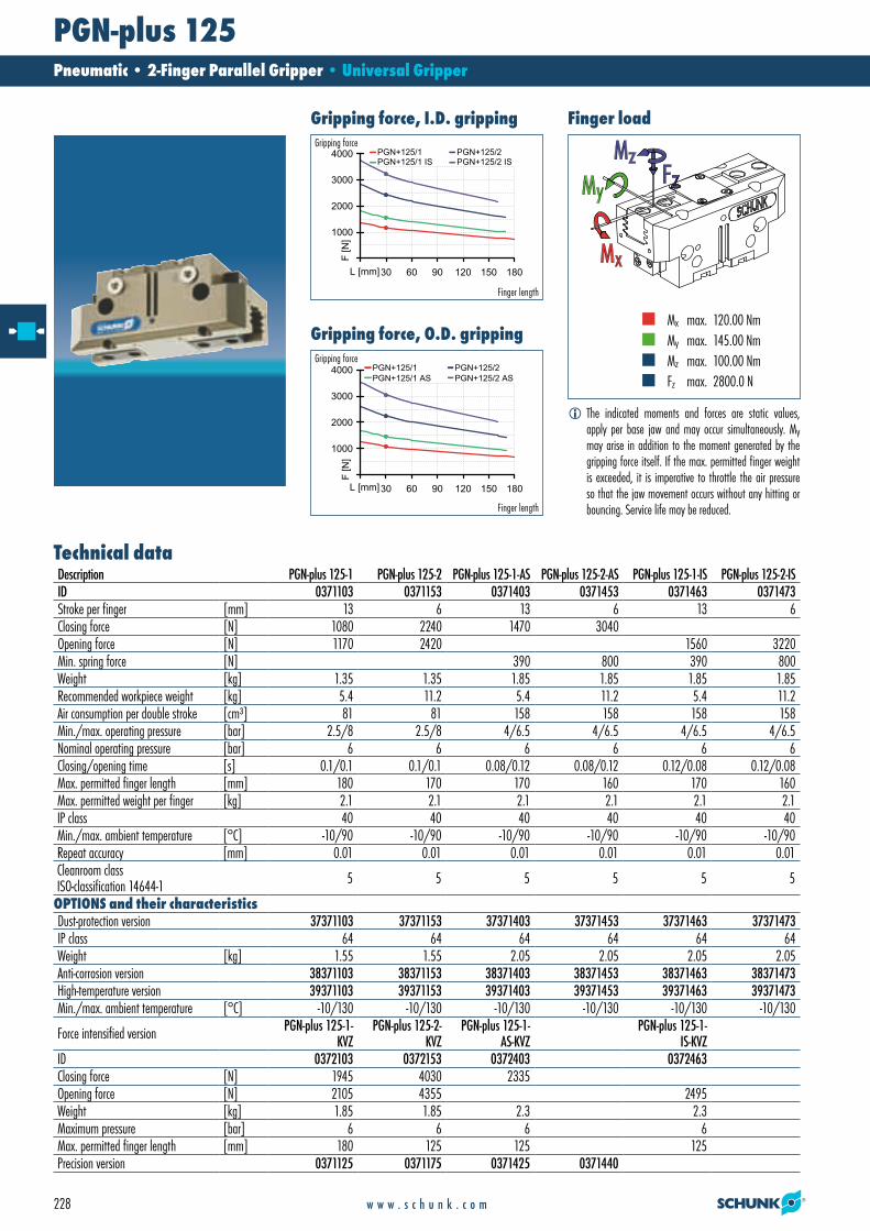
Gripping force, I.D. grippingGripping force
Finger length
Gripping force, O.D. grippingGripping force
Finger length
Finger load
Mx max. 120.00 Nm My max. 145.00 Nm Mz max. 100.00 Nm Fz max. 2800.0 N
iThe indicated moments and forces are static values, apply per base jaw and may occur simultaneously. My may arise in addition to the moment generated by the gripping force itself. If the max. permitted finger weight is exceeded, it is imperative to throttle the air pressure so that the jaw movement occurs without any hitting or bouncing. Service life may be reduced.
Description PGN-plus 125-1 PGN-plus 125-2 PGN-plus 125-1-AS PGN-plus 125-2-AS PGN-plus 125-1-IS PGN-plus 125-2-ISID 0371103 0371153 0371403 0371453 0371463 0371473Stroke per finger [mm] 13 6 13 6 13 6Closing force [N] 1080 2240 1470 3040Opening force [N] 1170 2420 1560 3220Min. spring force [N] 390 800 390 800Weight [kg] 1.35 1.35 1.85 1.85 1.85 1.85Recommended workpiece weight [kg] 5.4 11.2 5.4 11.2 5.4 11.2Air consumption per double stroke [cm³] 81 81 158 158 158 158Min./max. operating pressure [bar] 2.5/8 2.5/8 4/6.5 4/6.5 4/6.5 4/6.5Nominal operating pressure [bar] 6 6 6 6 6 6Closing/opening time [s] 0.1/0.1 0.1/0.1 0.08/0.12 0.08/0.12 0.12/0.08 0.12/0.08Max. permitted finger length [mm] 180 170 170 160 170 160Max. permitted weight per finger [kg] 2.1 2.1 2.1 2.1 2.1 2.1IP class 40 40 40 40 40 40Min./max. ambient temperature [°C] -10/90 -10/90 -10/90 -10/90 -10/90 -10/90Repeat accuracy [mm] 0.01 0.01 0.01 0.01 0.01 0.01Cleanroom class ISO-classification 14644-1 5 5 5 5 5 5
Dust-protection version 37371103 37371153 37371403 37371453 37371463 37371473IP class 64 64 64 64 64 64Weight [kg] 1.55 1.55 2.05 2.05 2.05 2.05Anti-corrosion version 38371103 38371153 38371403 38371453 38371463 38371473High-temperature version 39371103 39371153 39371403 39371453 39371463 39371473Min./max. ambient temperature [°C] -10/130 -10/130 -10/130 -10/130 -10/130 -10/130
Force intensified version PGN-plus 125-1-KVZ
PGN-plus 125-2-KVZ
PGN-plus 125-1-AS-KVZ
PGN-plus 125-1-IS-KVZ
ID 0372103 0372153 0372403 0372463Closing force [N] 1945 4030 2335Opening force [N] 2105 4355 2495Weight [kg] 1.85 1.85 2.3 2.3Maximum pressure [bar] 6 6 6 6Max. permitted finger length [mm] 180 125 125 125Precision version 0371125 0371175 0371425 0371440
Technical data
OPTIONS and their characteristics
01.06_Baureihe PGN_cs4.indd 228 10.06.2010 11:06:16

229w w w . s c h u n k . c o m
PGN-plus 125Pneumatic • 2-Finger Parallel Gripper • Universal Gripper
Main view
The drawing shows the gripper in the basic version with closed jaws, the dimensions do not include the options described below.
A, a Main/direct connection, gripper openingB, b Main/direct connection, gripper closingS Air purge connection, or deaeration bore1 Gripper connection
2 Finger connectionHT Depth of the centering sleeve hole in the
matching partiThe SDV-P pressure maintenance valve can also be used for I.D. or O.D. gripping alter-
natively or in addition to the spring-loaded, mechanical gripping force maintenance device (see “Accessories” catalog section).
Hose-free direct connection
3 Adapter4 Gripper
The direct connection is used for supplying compressed air without hoses. Instead, the pressure medium is fed through bore-holes in the mounting plate.
AS/IS gripping force maintenance device
The mechanical gripping force maintenance device ensures a minimum gripping force even in case of pressure drop. This acts as closing force in the AS version, and as opening force in the IS version. In addition, the gripping force maintenance device can also be used for increasing the gripping force or for single-acting gripping.
01.06_Baureihe PGN_cs4.indd 229 10.06.2010 11:06:19
230
PGN-plus 125 Pneumatic • 2-Finger Parallel Gripper • Universal Gripper
w w w . s c h u n k . c o m
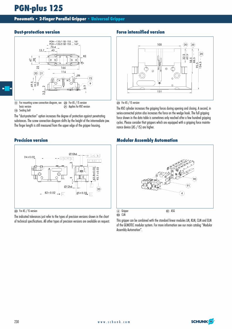
Dust-protection version
9 For mounting screw connection diagram, see basic version
AO Sealing bolt
BT For AS / IS versionBK Applies for KVZ version
The “dust-protection” option increases the degree of protection against penetrating substances. The screw connection diagram shifts by the height of the intermediate jaw. The finger length is still measured from the upper edge of the gripper housing.
Force intensified version
BT For AS / IS version
The KVZ cylinder increases the gripping forces during opening and closing. A second, in series-connected piston also increases the force on the wedge hook. The full gripping force shown in the data table is sometimes only reached after a few hundred gripping cycles. Please consider that grippers which are equipped with a gripping force mainte-nance device (AS / IS) are higher.
Precision version
BT For AS / IS version
The indicated tolerances just refer to the types of precision versions shown in the chart of technical specifications. All other types of precision versions are available on request.
Modular Assembly Automation
4 GripperIT CLM
IK ASG
This gripper can be combined with the standard linear modules LM, KLM, CLM and ELM of the GEMOTEC modular system. For more information see our main catalog “Modular Assembly Automation”.
01.06_Baureihe PGN_cs4.indd 230 10.06.2010 11:06:23

231w w w . s c h u n k . c o m
PGN-plus 125Pneumatic • 2-Finger Parallel Gripper • Universal Gripper
You can find more detailed information and individual parts of the above-mentioned accessories in the “Accessories” catalog section.
y
z
Maximum permitted finger projection
Permitted range Inadmissible range
The curve applies to the basic version (stroke -1). For other versions, the curve will be parallel but offset in line with the max. permitted finger length.
Description ID Cleanroom class ISO-classification 14644-1
Protection coverHUE PGN-plus 125 0371483 2
Protection cover
9 For mounting screw connection diagram, see basic version
The HUE protective cover completely protects the gripper against external influences up to IP65 if an additional sealing of the cover bottom is provided as part of the applica-tion. The mounting diagram shifts by the height of the intermediate jaw.
Description IDQuick-change Jaw System adapterBSWS-A 125 0303028Quick-change Jaw System baseBSWS-B 125 0303029Quick-change Jaw System reversedBSWS-U 125 0303044
Quick-change Jaw System
1 Gripper connection2 Finger connection9 For mounting screw connection diagram, see
basic version
EQ Locking
The BSWS quick-change jaw system enables top jaws to be changed on the gripper manually and rapidly. An adapter (BSWS-A) and a base (BSWS-B) are required for each gripper jaw.For a reverse assembly without height set-up, one adapter (BSWS-A) and a kit (BSWS-U) per gripper jaw are required. Another effect of the BSWS-U is, that there are no disturbing fastening bores in the finger contour.
01.06_Baureihe PGN_cs4.indd 231 10.06.2010 11:06:24
232
PGN-plus 125 Pneumatic • 2-Finger Parallel Gripper • Universal Gripper
w w w . s c h u n k . c o m
You can find more detailed information and individual parts of the above-mentioned accessories in the “Accessories” catalog section.
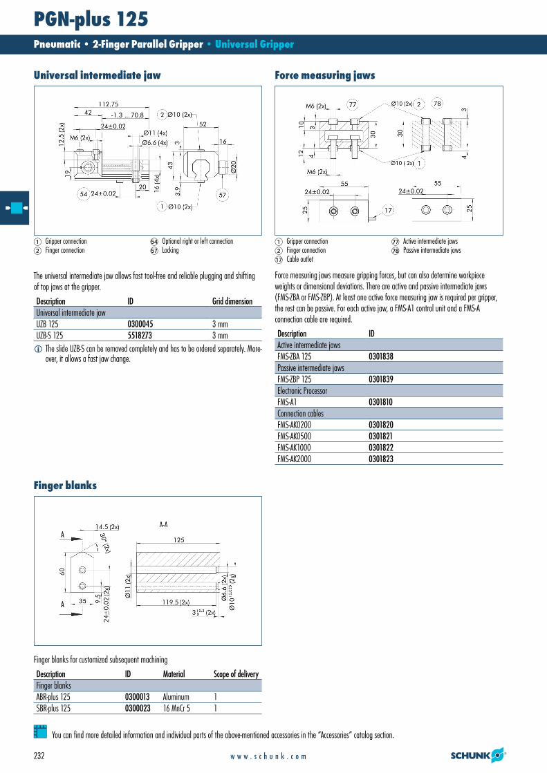
Description ID Grid dimensionUniversal intermediate jawUZB 125 0300045 3 mmUZB-S 125 5518273 3 mm
Universal intermediate jaw
1 Gripper connection2 Finger connection
EN Optional right or left connectionEQ Locking
The universal intermediate jaw allows fast tool-free and reliable plugging and shifting of top jaws at the gripper.
iThe slide UZB-S can be removed completely and has to be ordered separately. More-over, it allows a fast jaw change.
Description IDActive intermediate jawsFMS-ZBA 125 0301838Passive intermediate jawsFMS-ZBP 125 0301839Electronic ProcessorFMS-A1 0301810Connection cablesFMS-AK0200 0301820FMS-AK0500 0301821FMS-AK1000 0301822FMS-AK2000 0301823
Force measuring jaws
1 Gripper connection2 Finger connectionAQ Cable outlet
GQ Active intermediate jawsGR Passive intermediate jaws
Force measuring jaws measure gripping forces, but can also determine workpiece weights or dimensional deviations. There are active and passive intermediate jaws (FMS-ZBA or FMS-ZBP). At least one active force measuring jaw is required per gripper, the rest can be passive. For each active jaw, a FMS-A1 control unit and a FMS-A connection cable are required.
Description ID Material Scope of deliveryFinger blanksABR-plus 125 0300013 Aluminum 1SBR-plus 125 0300023 16 MnCr 5 1
Finger blanks
Finger blanks for customized subsequent machining
01.06_Baureihe PGN_cs4.indd 232 10.06.2010 11:06:27

233w w w . s c h u n k . c o m
PGN-plus 125Pneumatic • 2-Finger Parallel Gripper • Universal Gripper
You can find more detailed information and individual parts of the above-mentioned accessories in the “Accessories” catalog section.
Description ID Locking DeflectionCompensation unitTCU-125-3-MV-P 0324828 Yes ±1.5°/±1°/±1.5°TCU-125-3-OV-P 0324829 No ±1.5°/±1°/±1.5°
Tolerance compensation unit
IT Monitoring of locking
Grippers can be directly mounted without an adapter plate. Tolerance compensation unit and gripper have an identical screw connection diagram. Therefore the tolerance compensation units can be assembled later. Please consider the additional assembly height of the tolerance compensation unit. For details see catalog “Robot Accessories”. Description ID Compensation
travel Reset force
Compensation unitAGE-F-XY-080-1 0324960 ±5 mm 28.3 NAGE-F-XY-080-2 0324961 ±5 mm 42.5 NAGE-F-XY-080-3 0324962 ±5 mm 47.6 N
Compensation unit with spring reset
IT Monitoring
Grippers can be directly mounted without using an adapter plate. For details see our catalog “Robot Accessories”.
Description IDAttachment valvesABV-MV30-G1/8 0303328ABV-MV30-G1/8-V2-M8 0303396ABV-MV30-G1/8-V4-M8 0303366ABV-MV30-G1/8-V8-M8 0303367
Attachment valves
4 GripperAQ Cable outletAS Air connection
DR HoseEP Included in deliveryES Monitoring “gripping”
For each gripper one attachment valve ABV is required, optional with distributor for sensors and valves. Attachment valves increase the efficiency, reduce the installation work and air consumption and simplify air supply. For details please refer to the “Accessories” catalog section.
Description ID Recommended productProgrammable magnetic switchMMS-P 22-S-M8-PNP 0301370 •MMSK-P 22-S-PNP 0301371Connection cablesKA BG08-L 4P-0500 0307767KA BG08-L 4P-1000 0307768KA BW08-L 4P-0500 0307765KA BW08-L 4P-1000 0307766Sensor DistributorV2-M8-4P-2XM8-3P 0301380
Programmable magnetic switch
GN Stop for MMS-P
Position monitoring with two programmable positions per sensor. The end position monitoring is mounted in the C-slot.
iPlease note the minimum permitted bending radii for the sensor cables, which are generally 35 mm.
iPer gripper one sensor (closer/NO) is required, optionally a cable extension.
01.06_Baureihe PGN_cs4.indd 233 10.06.2010 11:06:29
234
PGN-plus 125 Pneumatic • 2-Finger Parallel Gripper • Universal Gripper
w w w . s c h u n k . c o m
You can find more detailed information and individual parts of the above-mentioned accessories in the “Accessories” catalog section.
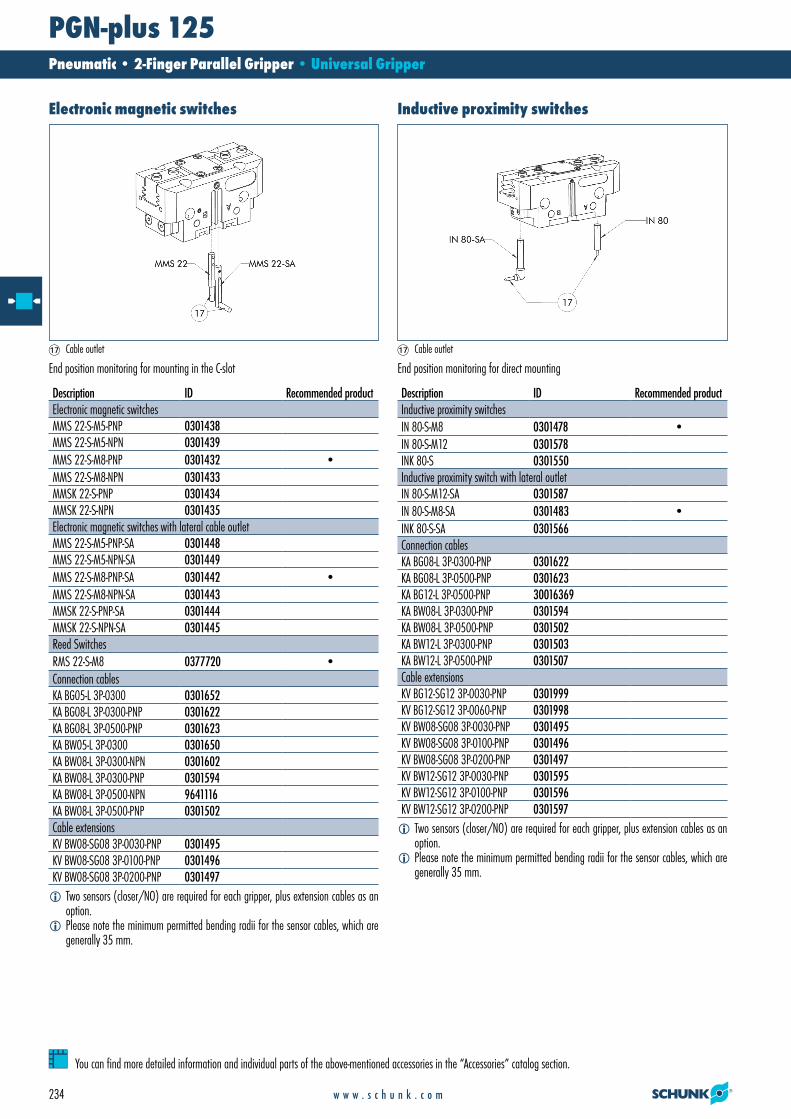
Description ID Recommended productElectronic magnetic switchesMMS 22-S-M5-PNP 0301438MMS 22-S-M5-NPN 0301439MMS 22-S-M8-PNP 0301432 •MMS 22-S-M8-NPN 0301433MMSK 22-S-PNP 0301434MMSK 22-S-NPN 0301435Electronic magnetic switches with lateral cable outletMMS 22-S-M5-PNP-SA 0301448MMS 22-S-M5-NPN-SA 0301449MMS 22-S-M8-PNP-SA 0301442 •MMS 22-S-M8-NPN-SA 0301443MMSK 22-S-PNP-SA 0301444MMSK 22-S-NPN-SA 0301445Reed SwitchesRMS 22-S-M8 0377720 •Connection cablesKA BG05-L 3P-0300 0301652KA BG08-L 3P-0300-PNP 0301622KA BG08-L 3P-0500-PNP 0301623KA BW05-L 3P-0300 0301650KA BW08-L 3P-0300-NPN 0301602KA BW08-L 3P-0300-PNP 0301594KA BW08-L 3P-0500-NPN 9641116KA BW08-L 3P-0500-PNP 0301502Cable extensionsKV BW08-SG08 3P-0030-PNP 0301495KV BW08-SG08 3P-0100-PNP 0301496KV BW08-SG08 3P-0200-PNP 0301497
Electronic magnetic switches
AQ Cable outlet
End position monitoring for mounting in the C-slot
iTwo sensors (closer/NO) are required for each gripper, plus extension cables as an option.
iPlease note the minimum permitted bending radii for the sensor cables, which are generally 35 mm.
Description ID Recommended productInductive proximity switchesIN 80-S-M8 0301478 •IN 80-S-M12 0301578INK 80-S 0301550Inductive proximity switch with lateral outletIN 80-S-M12-SA 0301587IN 80-S-M8-SA 0301483 •INK 80-S-SA 0301566Connection cablesKA BG08-L 3P-0300-PNP 0301622KA BG08-L 3P-0500-PNP 0301623KA BG12-L 3P-0500-PNP 30016369KA BW08-L 3P-0300-PNP 0301594KA BW08-L 3P-0500-PNP 0301502KA BW12-L 3P-0300-PNP 0301503KA BW12-L 3P-0500-PNP 0301507Cable extensionsKV BG12-SG12 3P-0030-PNP 0301999KV BG12-SG12 3P-0060-PNP 0301998KV BW08-SG08 3P-0030-PNP 0301495KV BW08-SG08 3P-0100-PNP 0301496KV BW08-SG08 3P-0200-PNP 0301497KV BW12-SG12 3P-0030-PNP 0301595KV BW12-SG12 3P-0100-PNP 0301596KV BW12-SG12 3P-0200-PNP 0301597
Inductive proximity switches
AQ Cable outlet
End position monitoring for direct mounting
iTwo sensors (closer/NO) are required for each gripper, plus extension cables as an option.
iPlease note the minimum permitted bending radii for the sensor cables, which are generally 35 mm.
01.06_Baureihe PGN_cs4.indd 234 10.06.2010 11:06:31

235w w w . s c h u n k . c o m
PGN-plus 125Pneumatic • 2-Finger Parallel Gripper • Universal Gripper
You can find more detailed information and individual parts of the above-mentioned accessories in the “Accessories” catalog section.
Description IDMounting kit for proximity switchAS-RMS 80 PGN/PZN-plus 100/125 0377726
Reed SwitchesRMS 80-S-M8 0377721
Cylindrical Reed Switches
End position monitoring mounted with mounting kit
iTwo sensors (closer/NO) are required for each gripper, plus extension cables as an option.
iThis mounting kit needs to be ordered optionally as an accessory.iPlease note the minimum permitted bending radii for the sensor cables, which are
generally 35 mm.
Description IDMounting kitAS-APS-M1-125/1 0302081AS-APS-M1-125/2 0302082Connection cablesAPS-K0200 0302066APS-K0700 0302068Electronic ProcessorAPS-M1E 0302064SensorAPS-M1S 0302062
Analog position sensor
Analog multi position monitoring for any desired positions
iWhen using an APS system, for each gripper a mounting kit (AS-APS), an APS sensor (APS-M 1S, incl. 3 m cable) as well as an electronics (APS-M1e) are required.
iAn extension cable (APS-K) can be connected between the sensor and the electronics as an option. The max. cable length between the sensor and the electronics is 10 m, between the electronics and their control unit (PLC) it is max. 1 m.
01.06_Baureihe PGN_cs4.indd 235 10.06.2010 11:06:32
236
PGN-plus 125 Pneumatic • 2-Finger Parallel Gripper • Universal Gripper
w w w . s c h u n k . c o m
You can find more detailed information and individual parts of the above-mentioned accessories in the “Accessories” catalog section.
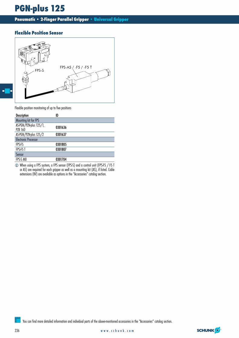
Description IDMounting kit for FPSAS-PGN/PZN-plus 125/1, PZB 160 0301636
AS-PGN/PZN-plus 125/2 0301637Electronic ProcessorFPS-F5 0301805FPS-F5 T 0301807SensorFPS-S M8 0301704
Flexible Position Sensor
Flexible position monitoring of up to five positions
iWhen using a FPS system, a FPS sensor (FPS-S) and a control unit (FPS-F5 / F5 T or A5) are required for each gripper as well as a mounting kit (AS), if listed. Cable extensions (KV) are available as options in the “Accessories” catalog section.
01.06_Baureihe PGN_cs4.indd 236 10.06.2010 11:06:33
Related Documents