PSH Pneumatic · 2-Finger Parallel Gripper · Long-stroke Gripper 426 www.schunk.com Sizes 22 .. 52 Weight 0.77 kg .. 8.05 kg Gripping force 320 N .. 1760 N Stroke per finger 14 mm .. 64 mm Workpiece weight 1.60 kg .. 8.80 kg Application example Rapid loading and unloading unit on a swivel head base. Due to the sturdiness of this unit, it is particularly suitable for use in machine tools. PSH 22-2 2-Finger Parallel Gripper PSK 34 Swivel Head

Welcome message from author
This document is posted to help you gain knowledge. Please leave a comment to let me know what you think about it! Share it to your friends and learn new things together.
Transcript

PSHPneumatic · 2-Finger Parallel Gripper · Long-stroke Gripper
426 w w w . s c h u n k . c o m
Sizes22 .. 52
Weight0.77 kg .. 8.05 kg
Gripping force320 N .. 1760 N
Stroke per finger14 mm .. 64 mm
Workpiece weight1.60 kg .. 8.80 kg
Application example
Rapid loading and unloading unit on aswivel head base. Due to the sturdiness ofthis unit, it is particularly suitable for usein machine tools.
PSH 22-2 2-Finger Parallel Gripper PSK 34 Swivel Head

PSHPneumatic · 2-Finger Parallel Gripper · Long-stroke Gripper
427w w w . s c h u n k . c o m
High maximum load capabilities possiblesuitable for the use of long gripper fingers
Dirt-protected round guidessealed, for long strokes
Attached to two gripper sides with centeringfor universal and flexible gripper mounting
Air supply via hose-free direct connection or screwconnectionsfor the flexible supply of compressed air in all automation systems
Comprehensive sensor accessoriesfor diverse monitoring tasks and stroke position monitoring
2-Finger parallel gripper with long jaw stroke and dirt-resistantround guides
Long-stroke Gripper
Area of applicationfor slightly dirty working environments and a broad range of parts
Your advantages and benefits
General information on the seriesWorking principlePneumatic double piston system synchronized by rack and pinion principle
Housing materialAluminum alloy, hard-anodized
Base jaw materialAluminum alloy, hard-anodized
ActuationPneumatic, with filtered compressed air (10 µm): Dry, lubricated or non-lubricatedPressure medium: Requirements on quality of the compressed air according to DIN ISO 8573-1: 6 4 4.
Warranty24 months
Scope of deliveryCentering sleeves, O-rings for direct connection, assembly and operating manual withmanufacturer’s declaration
Maintenance of gripping forcePossible with SDV-P pressure maintenance valve

PSHPneumatic · 2-Finger Parallel Gripper · Long-stroke Gripper
428 w w w . s c h u n k . c o m
Base jawfor the connection of workpiece-specificgripper fingers
Kinematicsrack and pinion principle for centric gripping
Housingweight-reduced through the use of a hard-anodized, high-strength aluminum alloy
Round guidessealed, for long strokes
The application of pressure on the pistons sets the base jaws, each of which issecured to the piston and the rack, in motion. The jaw stroke is synchronized bymeans of rack and pinion kinematics.
Function descriptionFinger positioncan be monitored by magnetic and/or inductive proximity switches. Unsynchronizedversion available on request as a special design.
Options and special information
Sectional diagram

PSHPneumatic · 2-Finger Parallel Gripper · Long-stroke Gripper
429w w w . s c h u n k . c o m
Gripping forceis the arithmetic total of the gripping force applied to each base jaw at distance P(see illustration), measured from the upper edge of the gripper.
Finger lengthis measured from the upper edge of the gripper housing in the direction of the mainaxis.
Repeat accuracyis defined as the spread of the limit position after 100 consecutive strokes.
Workpiece weightThe recommended workpiece weight is calculated for a force-type connection with acoefficient of friction of 0.1 and a safety factor of 2 against slippage of theworkpiece on acceleration due to gravity g. Considerably heavier workpiece weightsare permitted with form-fit gripping.
Closing and opening timesClosing and opening times are purely the times that the base jaws or fingers are inmotion. Valve switching times, hose filling times or PLC reaction times are notincluded in the above times and must be taken into consideration when determiningcycle times.
General information on the series
Accessories from SCHUNK –the suitable supplement formaximum functionality,reliability and performance ofall automation modules.
Centering sleeves Fittings MMS magnetic switchesIN inductive proximityswitches
Quentes plastic inserts
HKI gripper pads V sensor distributors
SDV-P pressuremaintenance valves
FPS flexible positionsensor
Accessories
KV/KA sensor cables
� For the exact size of the required accessories, availability of this size and the designation and ID, please refer to the additional views at the end of the size in question. You will find more detailed information on our accessory range in the “Accessories” catalog section.

PSH 22Pneumatic · 2-Finger Parallel Gripper · Long-stroke Gripper
430 w w w . s c h u n k . c o m
Technical data
Finger load
� Moments and forces apply per base jaw and may occursimultaneously. My may arise in addition to the momentgenerated by the gripping force itself. If the max.permitted finger weight is exceeded, it is imperative tothrottle the air pressure so that the jaw movement occurswithout any hitting or bouncing. Service life may reduce.
Gripping force, I.D. gripping
Gripping force, O.D. gripping
0
100
200
300
400
500
600
0 20 40 60 80 100 120 140L [mm]
F [
N]
PSH 22 / 4 bar PSH 22 / 6 bar
PSH 22 / 8 bar
0
100
200
300
400
500
600
0 20 40 60 80 100 120 140L [mm]
F [
N]
PSH 22 / 4 bar PSH 22 / 6 bar
PSH 22 / 8 bar
Gripping force
Finger length
Gripping force
Finger length
Mx max. 20.0 NmMy max. 10.0 NmMz max. 10.0 NmFz max. 200.0 N
Description PSH 22-1 PSH 22-2ID 0302122 0302123
Stroke per finger [mm] 28.0 14.0Closing force [N] 320.0 320.0Opening force [N] 320.0 320.0Weight [kg] 0.95 0.77Recommended workpiece weight [kg] 1.6 1.6Air consumption per double stroke [cm3] 36.0 18.0Nominal pressure [bar] 6.0 6.0Minimum pressure [bar] 3.0 3.0Maximum pressure [bar] 8.0 8.0Closing time [s] 0.1 0.08Opening time [s] 0.1 0.08Max. permitted finger length [mm] 140.0 140.0Max. permitted weight per finger [kg] 0.8 0.8IP class 67 67Min. ambient temperature [°C] -10.0 -10.0Max. ambient temperature [°C] 90.0 90.0Repeat accuracy [mm] 0.1 0.1
PSH 22Pneumatic · 2-Finger Parallel Gripper · Long-stroke Gripper
431w w w . s c h u n k . c o m
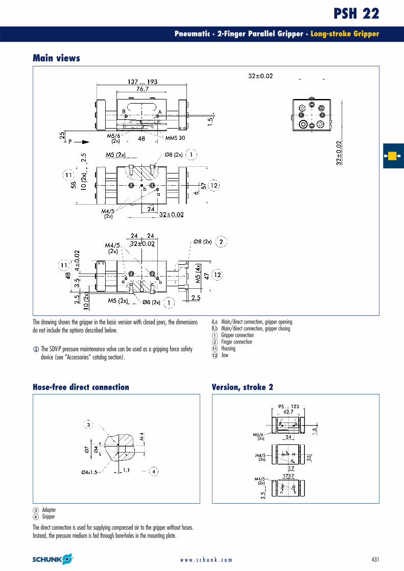
The direct connection is used for supplying compressed air to the gripper without hoses.Instead, the pressure medium is fed through bore-holes in the mounting plate.
� Adapter� Gripper
Main views
The drawing shows the gripper in the basic version with closed jaws, the dimensionsdo not include the options described below.
A,a Main/direct connection, gripper openingB,b Main/direct connection, gripper closing� Gripper connection� Finger connection�� Housing�� Jaw
Version, stroke 2
� The SDV-P pressure maintenance valve can be used as a gripping force safetydevice (see “Accessories” catalog section).
Hose-free direct connection
PSH 22Pneumatic · 2-Finger Parallel Gripper · Long-stroke Gripper
432 w w w . s c h u n k . c o m
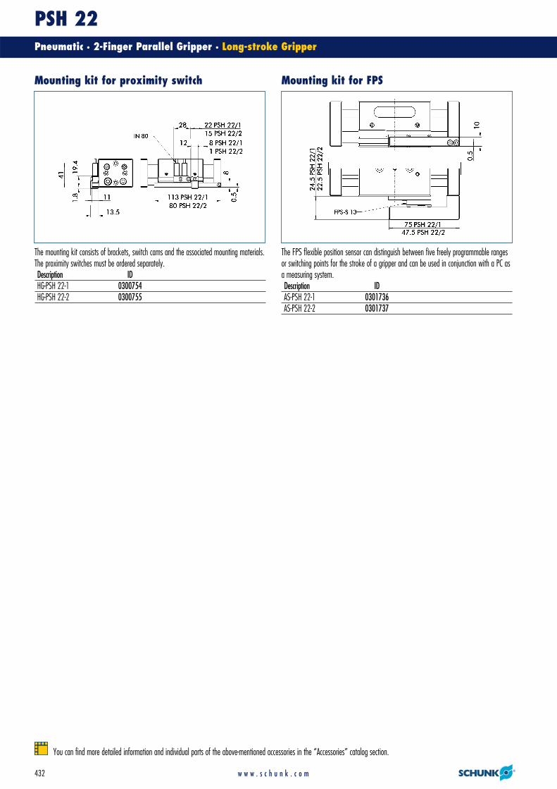
The FPS flexible position sensor can distinguish between five freely programmable rangesor switching points for the stroke of a gripper and can be used in conjunction with a PC asa measuring system.Description IDAS-PSH 22-1 0301736AS-PSH 22-2 0301737
The mounting kit consists of brackets, switch cams and the associated mounting materials.The proximity switches must be ordered separately.Description IDHG-PSH 22-1 0300754HG-PSH 22-2 0300755
Mounting kit for proximity switch Mounting kit for FPS
You can find more detailed information and individual parts of the above-mentioned accessories in the “Accessories” catalog section.

PSH 22Pneumatic · 2-Finger Parallel Gripper · Long-stroke Gripper
433w w w . s c h u n k . c o m
� When using an FPS system, an FPS sensor (FPS-S) and an control unit (FPS-F5 / F5 T or A5) are required for each gripper as well as a mounting kit (AS), if listed.Cable extensions (KV) are available as options in the “Accessories” catalog section.
� Please note the minimum permitted bending radii for the sensor cables, which aregenerally 35 mm.
� Two sensors (NO contacts) are required for each gripper, plus extension cables as anoption.
� Two sensors (NO contacts) are required for each gripper, plus extension cables as anoption.
Measuring system:FPS Flexible position sensorDescription IDAS-PSH 22-1 0301736AS-PSH 22-2 0301737FPS-F5 0301805FPS-F5 T 0301807FPS-S 13 0301705
End position monitoring: Inductive proximity switches, mounted with mounting kitDescription ID Recommended productHG-PSH 22-1 0300754HG-PSH 22-2 0300755IN 80-S-M12 0301578IN 80-S-M8 0301478 •IN-C 80-S-M8 0301475INK 80-S 0301550INK 80-SL 0301579
End position monitoring: Electronic magnetic switches, for mounting in C-slotDescription ID Recommended productMMS 30-S-M12-PNP 0301571MMS 30-S-M8-PNP 0301471 •MMSK 30-S-PNP 0301563
Sensor system
You can find more detailed information and individual parts of the above-mentioned accessories in the “Accessories” catalog section.
Extension cables for proximity switches/magnetic switchesDescription IDKA BG08-L 3P-0300-PNP 0301622KA BW08-L 3P-0300-PNP 0301594KA BW08-L 3P-0500-PNP 0301502KA BW12-L 3P-0300-PNP 0301503KA BW12-L 3P-0500-PNP 0301507KV BW08-SG08 3P-0030-PNP 0301495KV BW08-SG08 3P-0100-PNP 0301496KV BW08-SG08 3P-0200-PNP 0301497KV BW12-SG12 3P-0030-PNP 0301595KV BW12-SG12 3P-0100-PNP 0301596KV BW12-SG12 3P-0200-PNP 0301597

PSH 32Pneumatic · 2-Finger Parallel Gripper · Long-stroke Gripper
434 w w w . s c h u n k . c o m
Technical data
Finger load
� Moments and forces apply per base jaw and may occursimultaneously. My may arise in addition to the momentgenerated by the gripping force itself. If the max.permitted finger weight is exceeded, it is imperative tothrottle the air pressure so that the jaw movement occurswithout any hitting or bouncing. Service life may reduce.
Gripping force, I.D. gripping
Gripping force, O.D. gripping
200
400
600
800
1000
1200
0 25 50 75 100 125 150 175L [mm]
F [
N]
PSH 32 / 4 bar PSH 32 / 6 bar
PSH 32 / 8 bar
200
400
600
800
1000
1200
0 25 50 75 100 125 150 175L [mm]
F [
N]
PSH 32 / 4 bar PSH 32 / 6 bar
PSH 32 / 8 bar
Gripping force
Finger length
Gripping force
Finger length
Mx max. 20.0 NmMy max. 10.0 NmMz max. 10.0 NmFz max. 300.0 N
Description PSH 32-1 PSH 32-2ID 0302132 0302133
Stroke per finger [mm] 35.0 22.5Closing force [N] 750.0 750.0Opening force [N] 750.0 750.0Weight [kg] 2.05 1.8Recommended workpiece weight [kg] 3.75 3.75Air consumption per double stroke [cm3] 101.0 65.0Nominal pressure [bar] 6.0 6.0Minimum pressure [bar] 3.0 3.0Maximum pressure [bar] 8.0 8.0Closing time [s] 0.2 0.12Opening time [s] 0.2 0.12Max. permitted finger length [mm] 170.0 170.0Max. permitted weight per finger [kg] 1.5 1.5IP class 67 67Min. ambient temperature [°C] -10.0 -10.0Max. ambient temperature [°C] 90.0 90.0Repeat accuracy [mm] 0.1 0.1

PSH 32Pneumatic · 2-Finger Parallel Gripper · Long-stroke Gripper
435w w w . s c h u n k . c o m
The direct connection is used for supplying compressed air to the gripper without hoses.Instead, the pressure medium is fed through bore-holes in the mounting plate.
� Adapter� Gripper
Main views
The drawing shows the gripper in the basic version with closed jaws, the dimensionsdo not include the options described below.
A,a Main/direct connection, gripper openingB,b Main/direct connection, gripper closing� Gripper connection� Finger connection�� Housing�� Jaw
Version, stroke 2
� The SDV-P pressure maintenance valve can be used as a gripping force safetydevice (see “Accessories” catalog section).
Hose-free direct connection

PSH 32Pneumatic · 2-Finger Parallel Gripper · Long-stroke Gripper
436 w w w . s c h u n k . c o m
The FPS flexible position sensor can distinguish between five freely programmable rangesor switching points for the stroke of a gripper and can be used in conjunction with a PC asa measuring system.Description IDAS-PSH 32-2 0301738
The mounting kit consists of brackets, switch cams and the associated mounting materials.The proximity switches must be ordered separately.Description IDHG-PSH 32 0300756
Mounting kit for proximity switch Mounting kit for FPS
You can find more detailed information and individual parts of the above-mentioned accessories in the “Accessories” catalog section.

PSH 32Pneumatic · 2-Finger Parallel Gripper · Long-stroke Gripper
437w w w . s c h u n k . c o m
� When using an FPS system, an FPS sensor (FPS-S) and an control unit (FPS-F5 /F5 T or A5) are required for each gripper as well as a mounting kit (AS), if listed.Cable extensions (KV) are available as options in the “Accessories” catalog section.
� Please note the minimum permitted bending radii for the sensor cables, which aregenerally 35 mm.
� Two sensors (NO contacts) are required for each gripper, plus extension cables as anoption.
� Two sensors (NO contacts) are required for each gripper, plus extension cables as anoption.
Measuring system:FPS Flexible position sensorDescription IDAS-PSH 32-2 0301738FPS-F5 0301805FPS-F5 T 0301807FPS-S 13 0301705
End position monitoring: Inductive proximity switches, mounted with mounting kitDescription ID Recommended productHG-PSH 32 0300756IN 80-S-M12 0301578IN 80-S-M8 0301478 •IN-C 80-S-M8 0301475INK 80-S 0301550INK 80-SL 0301579
End position monitoring: Electronic magnetic switches, for mounting in C-slotDescription ID Recommended productMMS 30-S-M12-PNP 0301571MMS 30-S-M8-PNP 0301471 •MMSK 30-S-PNP 0301563
Sensor system
You can find more detailed information and individual parts of the above-mentioned accessories in the “Accessories” catalog section.
Extension cables for proximity switches/magnetic switchesDescription IDKA BG08-L 3P-0300-PNP 0301622KA BW08-L 3P-0300-PNP 0301594KA BW08-L 3P-0500-PNP 0301502KA BW12-L 3P-0300-PNP 0301503KA BW12-L 3P-0500-PNP 0301507KV BW08-SG08 3P-0030-PNP 0301495KV BW08-SG08 3P-0100-PNP 0301496KV BW08-SG08 3P-0200-PNP 0301497KV BW12-SG12 3P-0030-PNP 0301595KV BW12-SG12 3P-0100-PNP 0301596KV BW12-SG12 3P-0200-PNP 0301597

PSH 42Pneumatic · 2-Finger Parallel Gripper · Long-stroke Gripper
438 w w w . s c h u n k . c o m
Technical data
Finger load
� Moments and forces apply per base jaw and may occursimultaneously. My may arise in addition to the momentgenerated by the gripping force itself. If the max.permitted finger weight is exceeded, it is imperative tothrottle the air pressure so that the jaw movement occurswithout any hitting or bouncing. Service life may reduce.
Gripping force, I.D. gripping
Gripping force, O.D. gripping
0
400
800
1200
1600
2000
0 40 80 120 160 200 240L [mm]
PSH 42 / 4 bar PSH 42 / 6 bar
PSH 42 / 8 bar
0
400
800
1200
1600
2000
0 40 80 120 160 200 240L [mm]
PSH 42 / 4 bar PSH 42 / 6 bar
PSH 42 / 8 bar
Gripping force
Finger length
Gripping force
Finger length
Mx max. 25.0 NmMy max. 20.0 NmMz max. 25.0 NmFz max. 500.0 N
Description PSH 42-1 PSH 42-2ID 0302142 0302143
Stroke per finger [mm] 50.0 29.0Closing force [N] 1170.0 1170.0Opening force [N] 1170.0 1170.0Weight [kg] 4.65 3.9Recommended workpiece weight [kg] 4.25 4.25Air consumption per double stroke [cm3] 255.0 148.0Nominal pressure [bar] 6.0 6.0Minimum pressure [bar] 3.0 3.0Maximum pressure [bar] 8.0 8.0Closing time [s] 0.25 0.15Opening time [s] 0.25 0.15Max. permitted finger length [mm] 230.0 230.0Max. permitted weight per finger [kg] 2.5 2.5IP class 67 67Min. ambient temperature [°C] -10.0 -10.0Max. ambient temperature [°C] 90.0 90.0Repeat accuracy [mm] 0.05 0.05

PSH 42Pneumatic · 2-Finger Parallel Gripper · Long-stroke Gripper
439w w w . s c h u n k . c o m
The direct connection is used for supplying compressed air to the gripper without hoses.Instead, the pressure medium is fed through bore-holes in the mounting plate.
� Adapter � Gripper
Main views
The drawing shows the gripper in the basic version with closed jaws, the dimensionsdo not include the options described below.
A,a Main/direct connection, gripper openingB,b Main/direct connection, gripper closing� Gripper connection� Finger connection�� Housing�� Jaw
Version, stroke 2
� The SDV-P pressure maintenance valve can be used as a gripping force safetydevice (see “Accessories” catalog section).
Hose-free direct connection
PSH 42Pneumatic · 2-Finger Parallel Gripper · Long-stroke Gripper
440 w w w . s c h u n k . c o m
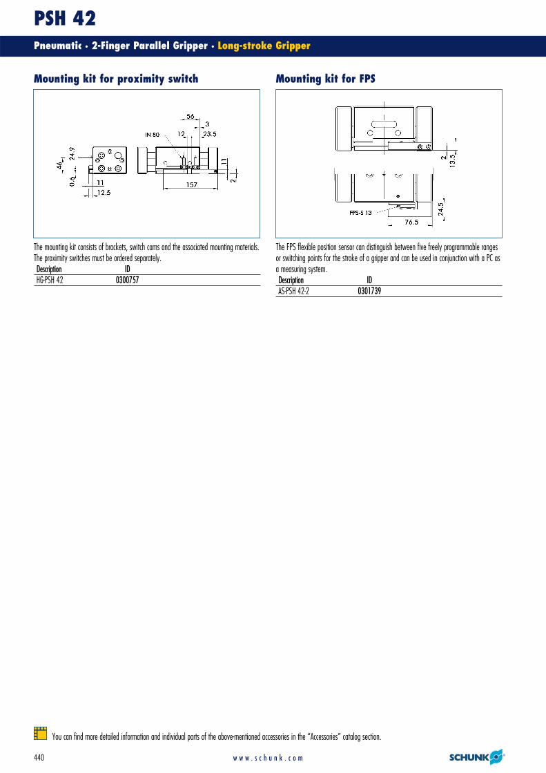
The FPS flexible position sensor can distinguish between five freely programmable rangesor switching points for the stroke of a gripper and can be used in conjunction with a PC asa measuring system.Description IDAS-PSH 42-2 0301739
The mounting kit consists of brackets, switch cams and the associated mounting materials.The proximity switches must be ordered separately.Description IDHG-PSH 42 0300757
Mounting kit for proximity switch Mounting kit for FPS
You can find more detailed information and individual parts of the above-mentioned accessories in the “Accessories” catalog section.

PSH 42Pneumatic · 2-Finger Parallel Gripper · Long-stroke Gripper
441w w w . s c h u n k . c o m
� When using an FPS system, an FPS sensor (FPS-S) and an control unit (FPS-F5 / F5 T or A5) are required for each gripper as well as a mounting kit (AS), if listed.Cable extensions (KV) are available as options in the “Accessories” catalog section.
� Please note the minimum permitted bending radii for the sensor cables, which aregenerally 35 mm.
� Two sensors (NO contacts) are required for each gripper, plus extension cables as anoption.
� Two sensors (NO contacts) are required for each gripper, plus extension cables as anoption.
Measuring system:FPS Flexible position sensorDescription IDAS-PSH 42-2 0301739FPS-F5 0301805FPS-F5 T 0301807FPS-S 13 0301705
End position monitoring: Inductive proximity switches, mounted with mounting kitDescription ID Recommended productHG-PSH 42 0300757IN 80-S-M12 0301578IN 80-S-M8 0301478 •IN-C 80-S-M8 0301475INK 80-S 0301550INK 80-SL 0301579
End position monitoring: Electronic magnetic switches, for mounting in C-slotDescription ID Recommended productMMS 30-S-M12-PNP 0301571MMS 30-S-M8-PNP 0301471 •MMSK 30-S-PNP 0301563
Sensor system
You can find more detailed information and individual parts of the above-mentioned accessories in the “Accessories” catalog section.
Extension cables for proximity switches/magnetic switchesDescription IDKA BG08-L 3P-0300-PNP 0301622KA BW08-L 3P-0300-PNP 0301594KA BW08-L 3P-0500-PNP 0301502KA BW12-L 3P-0300-PNP 0301503KA BW12-L 3P-0500-PNP 0301507KV BW08-SG08 3P-0030-PNP 0301495KV BW08-SG08 3P-0100-PNP 0301496KV BW08-SG08 3P-0200-PNP 0301497KV BW12-SG12 3P-0030-PNP 0301595KV BW12-SG12 3P-0100-PNP 0301596KV BW12-SG12 3P-0200-PNP 0301597
PSH 52Pneumatic · 2-Finger Parallel Gripper · Long-stroke Gripper
442 w w w . s c h u n k . c o m
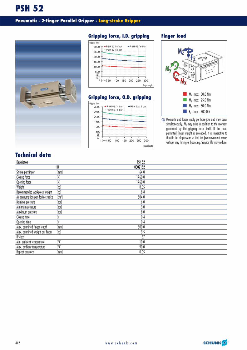
Technical data
Finger load
� Moments and forces apply per base jaw and may occursimultaneously. My may arise in addition to the momentgenerated by the gripping force itself. If the max.permitted finger weight is exceeded, it is imperative tothrottle the air pressure so that the jaw movement occurswithout any hitting or bouncing. Service life may reduce.
Gripping force, I.D. gripping
Gripping force, O.D. gripping
0
500
1000
1500
2000
2500
3000
0 50 100 150 200 250 300L [mm]
F [
N]
PSH 52 / 4 bar PSH 52 / 6 bar
PSH 52 / 8 bar
0
500
1000
1500
2000
2500
3000
0 50 100 150 200 250 300L [mm]
F [
N]
PSH 52 / 4 bar PSH 52 / 6 bar
PSH 52 / 8 bar
Gripping force
Finger length
Gripping force
Finger length
Mx max. 30.0 NmMy max. 25.0 NmMz max. 30.0 NmFz max. 700.0 N
Description PSH 52ID 0302152
Stroke per finger [mm] 64.0Closing force [N] 1760.0Opening force [N] 1760.0Weight [kg] 8.05Recommended workpiece weight [kg] 8.8Air consumption per double stroke [cm3] 504.0Nominal pressure [bar] 6.0Minimum pressure [bar] 3.0Maximum pressure [bar] 8.0Closing time [s] 0.4Opening time [s] 0.4Max. permitted finger length [mm] 300.0Max. permitted weight per finger [kg] 3.5IP class 67Min. ambient temperature [°C] -10.0Max. ambient temperature [°C] 90.0Repeat accuracy [mm] 0.05
PSH 52Pneumatic · 2-Finger Parallel Gripper · Long-stroke Gripper
443w w w . s c h u n k . c o m
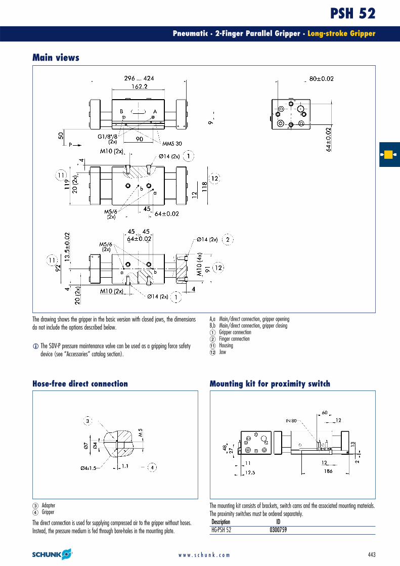
The mounting kit consists of brackets, switch cams and the associated mounting materials.The proximity switches must be ordered separately.Description IDHG-PSH 52 0300759
The direct connection is used for supplying compressed air to the gripper without hoses.Instead, the pressure medium is fed through bore-holes in the mounting plate.
� Adapter� Gripper
Main views
The drawing shows the gripper in the basic version with closed jaws, the dimensionsdo not include the options described below.
A,a Main/direct connection, gripper openingB,b Main/direct connection, gripper closing� Gripper connection� Finger connection�� Housing�� Jaw
Mounting kit for proximity switch
� The SDV-P pressure maintenance valve can be used as a gripping force safetydevice (see “Accessories” catalog section).
Hose-free direct connection

PSH 52Pneumatic · 2-Finger Parallel Gripper · Long-stroke Gripper
444 w w w . s c h u n k . c o m
� Please note the minimum permitted bending radii for the sensor cables, which aregenerally 35 mm.
� Two sensors (NO contacts) are required for each gripper, plus extension cables as anoption.
� Two sensors (NO contacts) are required for each gripper, plus extension cables as anoption.
End position monitoring: Inductive proximity switches, mounted with mounting kitDescription ID Recommended productHG-PSH 52 0300759IN 80-S-M12 0301578IN 80-S-M8 0301478 •IN-C 80-S-M8 0301475INK 80-S 0301550INK 80-SL 0301579
End position monitoring: Electronic magnetic switches, for mounting in C-slotDescription ID Recommended productMMS 30-S-M12-PNP 0301571MMS 30-S-M8-PNP 0301471 •MMSK 30-S-PNP 0301563
Sensor system
You can find more detailed information and individual parts of the above-mentioned accessories in the “Accessories” catalog section.
Extension cables for proximity switches/magnetic switchesDescription IDKA BG08-L 3P-0300-PNP 0301622KA BW08-L 3P-0300-PNP 0301594KA BW08-L 3P-0500-PNP 0301502KA BW12-L 3P-0300-PNP 0301503KA BW12-L 3P-0500-PNP 0301507KV BW08-SG08 3P-0030-PNP 0301495KV BW08-SG08 3P-0100-PNP 0301496KV BW08-SG08 3P-0200-PNP 0301497KV BW12-SG12 3P-0030-PNP 0301595KV BW12-SG12 3P-0100-PNP 0301596KV BW12-SG12 3P-0200-PNP 0301597
Related Documents