Automated Slide Gate Models: FLX-5363 FLX-5364 Operation Manual PNEG-2320 Version 1.0 Date: 10-27-20 PNEG-2320

Welcome message from author
This document is posted to help you gain knowledge. Please leave a comment to let me know what you think about it! Share it to your friends and learn new things together.
Transcript

Automated Slide Gate
Models:FLX-5363FLX-5364
Operation Manual
PNEG-2320Version 1.0
Date: 10-27-20
PNEG-2320

All information, illustrations, photos, and specifications in this manual are based on the latestinformation available at the time of publication. The right is reserved to make changes at anytime without notice.
2 PNEG-2320 Automated Slide Gate Operation

ContentsChapter 1 Safety Precautions ....................................................................................................................5
Safety Guidelines ........................................................................................................................5Cautionary Symbol Definitions......................................................................................................6Safety Cautions...........................................................................................................................7Safety Sign-off Sheet.................................................................................................................10
Chapter 2 General Specifications and Operation..................................................................................... 11General Overview ..................................................................................................................... 11Specifications ........................................................................................................................... 11User Interface ...........................................................................................................................12
Chapter 3 Configuring Settings for each Slide Gate ................................................................................13Adjustable Parameters ..............................................................................................................13Disabling an Actuator Slide ........................................................................................................14Enabling an Actuator Slide .........................................................................................................14Setting the Manual Operation .....................................................................................................15Setting the Auto Operation .........................................................................................................15Setting the Open Position ..........................................................................................................16Calibration ................................................................................................................................16Setting the Sensitivity ................................................................................................................17Setting the Node ID ...................................................................................................................17Clearing an Alarm .....................................................................................................................18
Chapter 4 General Movement/Operation..................................................................................................19Chapter 5 Manual Mode Operation ..........................................................................................................21Chapter 6 Slide Gate Operation using the Site Controller (FLX-5419) ......................................................23Chapter 7 Troubleshooting......................................................................................................................25
Clearing an Obstruction .............................................................................................................25Alarms......................................................................................................................................26Limited Warranty - Protein Products .......................................................................................27
PNEG-2320 Automated Slide Gate Operation 3

NOTES
4 PNEG-2320 Automated Slide Gate Operation

1 Safety PrecautionsTopics Covered in this Chapter
▪ Safety Guidelines▪ Cautionary Symbol Definitions▪ Safety Cautions▪ Safety Sign-off Sheet
Safety GuidelinesSafety guidelines are general-to-specific safety rules that must be followed at all times. This manual iswritten to help you understand safe operating procedures and problems that can be encountered by theoperator and other personnel when using this equipment. Read and save these instructions.
As owner or operator, you are responsible for understanding the requirements, hazards, and precautionsthat exist and to inform others as required. Unqualified persons must stay out of the work area at alltimes.
Alterations must not be made to the equipment. Alterations can produce dangerous situations resulting inSERIOUS INJURYor DEATH.
This equipment must be installed in accordance with the current installation codes and applicable regula-tions, which must be carefully followed in all cases. Authorities having jurisdiction must be consultedbefore installations are made.
When necessary, you must consider the installation location relative to electrical, fuel and water utilities.
Personnel operating or working around equipment must read this manual. This manual must be deliveredwith equipment to its owner. Failure to read this manual and its safety instructions is a misuse of theequipment.
ST-0001–4
PNEG-2320 Automated Slide Gate Operation 5

Chapter 1: Safety Precautions
Cautionary Symbol DefinitionsCautionary symbols appear in this manual and on product decals. The symbols alert the user of potentialsafety hazards, prohibited activities and mandatory actions. To help you recognize this information, weuse the symbols that are defined below.
Table 1-1 Description of the different cautionary symbols
Symbol Description
This symbol indicates an imminently hazardous situation which, ifnot avoided, will result in serious injury or death.
This symbol indicates a potentially hazardous situation which, if notavoided, can result in serious injury or death.
This symbol indicates a potentially hazardous situation which, if notavoided, can result in minor or moderate injury.
This symbol is used to address practices not related to personalinjury.
This symbol indicates a general hazard.
This symbol indicates a prohibited activity.
This symbol indicates a mandatory action.
ST-0005–2
6 PNEG-2320 Automated Slide Gate Operation
Chapter 1: Safety Precautions
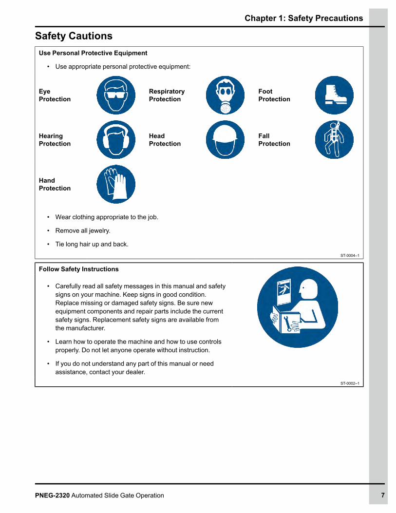
Safety CautionsUse Personal Protective Equipment
• Use appropriate personal protective equipment:
EyeProtection
RespiratoryProtection
FootProtection
HearingProtection
HeadProtection
FallProtection
HandProtection
• Wear clothing appropriate to the job.
• Remove all jewelry.
• Tie long hair up and back.ST-0004–1
Follow Safety Instructions
• Carefully read all safety messages in this manual and safetysigns on your machine. Keep signs in good condition.Replace missing or damaged safety signs. Be sure newequipment components and repair parts include the currentsafety signs. Replacement safety signs are available fromthe manufacturer.
• Learn how to operate the machine and how to use controlsproperly. Do not let anyone operate without instruction.
• If you do not understand any part of this manual or needassistance, contact your dealer.
ST-0002–1
PNEG-2320 Automated Slide Gate Operation 7

Chapter 1: Safety Precautions
Maintain Equipment and Work Area
• Understand service procedures before doing work. Keeparea clean and dry.
• Never service equipment while it is operating. Keep hands,feet, and clothing away from moving parts.
• Keep your equipment in proper working condition. Replaceworn or broken parts immediately.
ST-0003–1
Lifting Hazard
• Single person lift can cause injury.
• Use a mechanical lifting device to lift or move the equipmentduring installation.
ST-0021–2
Install and Operate Electrical Equipment Properly
• Electrical controls must be installed by a qualified electricianand must meet the standards set by applicable local codes(National Electrical Code for the US, Canadian ElectricCode, or EN60204 along with applicable European Direc-tives for Europe).
• Lock-out power source before making adjustments, cleaning,or maintaining equipment.
• Make sure all equipment is properly grounded.ST-0027–4
Sharp Edge Hazard
• This product has sharp edges, which can cause seriousinjury.
• To avoid injury, handle sharp edges with caution and alwaysuse proper protective clothing and equipment.
ST-0036–2
8 PNEG-2320 Automated Slide Gate Operation
Chapter 1: Safety Precautions
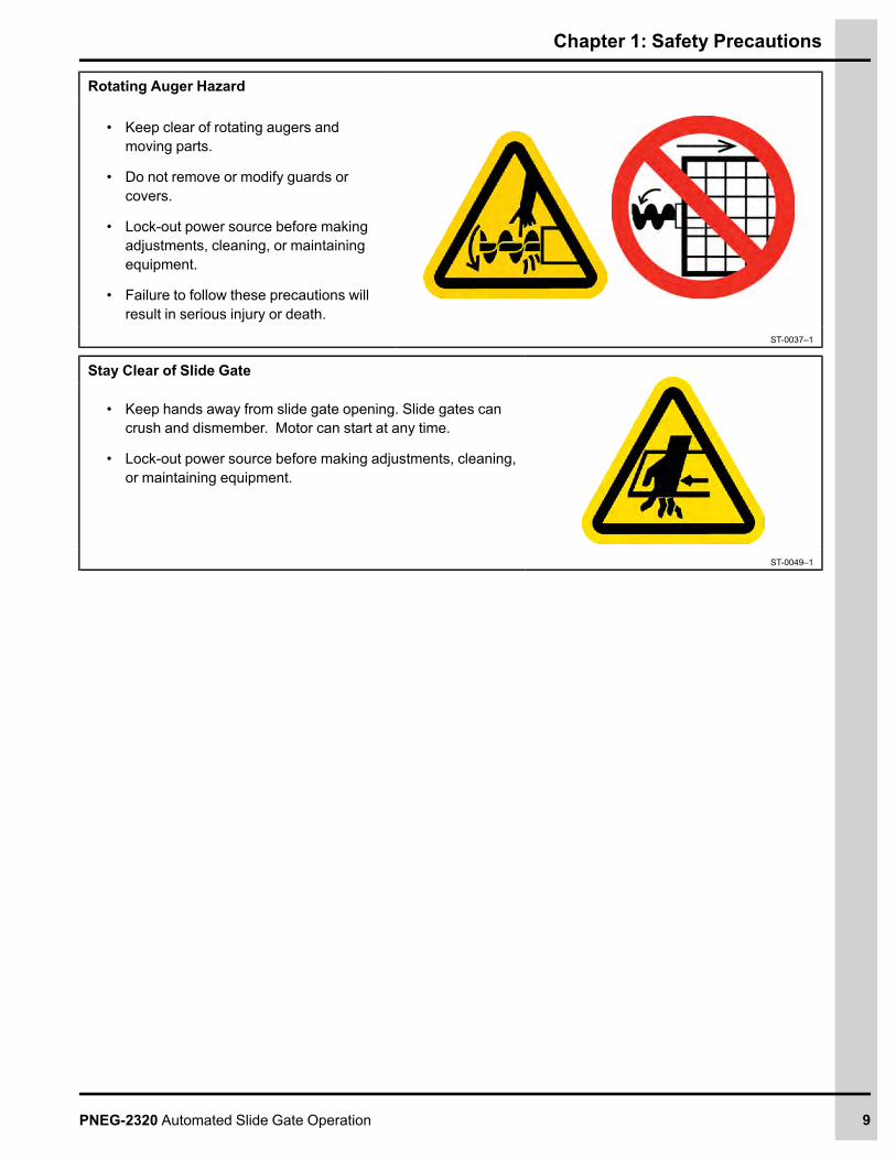
Rotating Auger Hazard
• Keep clear of rotating augers andmoving parts.
• Do not remove or modify guards orcovers.
• Lock-out power source before makingadjustments, cleaning, or maintainingequipment.
• Failure to follow these precautions willresult in serious injury or death.
ST-0037–1
Stay Clear of Slide Gate
• Keep hands away from slide gate opening. Slide gates cancrush and dismember. Motor can start at any time.
• Lock-out power source before making adjustments, cleaning,or maintaining equipment.
ST-0049–1
PNEG-2320 Automated Slide Gate Operation 9
Chapter 1: Safety Precautions
Safety Sign-off SheetBelow is a sign-off sheet that can be used to verify that all personnel have read and understood the safetyinstructions. This sign-off sheet is provided for your convenience and personal record keeping.
Date Employee Name Supervisor Name
ST-0007
10 PNEG-2320 Automated Slide Gate Operation
2 General Specifications andOperationTopics Covered in this Chapter
▪ General Overview▪ Specifications▪ User Interface
General Overview1. At start-up the unit will move the slide gate to the home position (the fully closed position) to
establish a known position.
2. The display will read “Slide 1:nn.n%” or “Slide 2:nn.n%”, depending on which slides are enabled.If no slides are enabled, it will read “No slides”.
3. Each local slide gate controller (FLX-5416) can be configured with a maximum of two slide gates.Each slide gate can be enabled or disabled. The controller is generally mounted to a bin leg. Eachcontroller can be given a node ID number to identify the bin where it is located.
4. Each slide gate site controller (FLX-5419) can control up to eight local slide gate controllers(FLX-5416) with up to sixteen slide gates. The site controller (FLX-5419) allows you to remotelyoperate the slide gates and set some parameters. It does not let you operate the slide gates inmanual mode.
5. The length of travel of the slide gate is a fixed length for all installations. The closed position isdetermined by a physical limit switch. The limit switch is always sending a signal to the controllerindicating whether the switch is active or not active. At the start-up, the controller will attempt toclose the slide until the limit switch is tripped, thus setting the home/closed position. The full openposition will be a fixed length from the closed position.
Specifications1. The local slide gate controller (FLX-5416) runs on 120VAC and each actuator has a FLA of 2.5
Amps. Each local controller (FLX-5416) has a maximum draw of 5 Amps.
2. The slide gate site controller (FLX-5419) runs on 24V DC and has a draw of 50 mA.
PNEG-2320 Automated Slide Gate Operation 11

Chapter 2: General Specifications and Operation
User InterfaceFigure 2-1 User interface
Table 2-1 Controller display and button details
Ref#
Display/Buttons Description
1 Display Displays current status information and parameter settings.
2 Menu Use to advance through the configuration screens.
3 Up Arrow Use to increase the value of a parameter and open the slide gate in manual override mode.
4 Down Arrow Use to decrease the value of a parameter and close the slide gate in manual override mode.
5 Enter Use to accept parameter settings.
12 PNEG-2320 Automated Slide Gate Operation
3 Configuring Settings for eachSlide GateTopics Covered in this Chapter
▪ Adjustable Parameters▪ Disabling an Actuator Slide▪ Enabling an Actuator Slide▪ Setting the Manual Operation▪ Setting the Auto Operation▪ Setting the Open Position▪ Calibration▪ Setting the Sensitivity▪ Setting the Node ID▪ Clearing an Alarm
Adjustable ParametersYou can set the following parameters for each actuated slide gate:
• Enable – Enables the slide gate to operate in auto ormanual mode.
• Disable – Disables the gate from operating.
• Auto – Automode will allow the slide gate to automatically operate to the positions set.
• Manual – Manualmode allows the user to use the up and down arrows to open and close the slidegate, usually used when troubleshooting or clearing a blockage. Control can only be operatedmanually while at the controller. Controlling the slide gate remotely via main controller is not allowedfor safety.
• Open position – The user can set the position of the slide gate using a percentage of 0.0% to100.0% for auto operation. 0.0% is a closed position and 100.0% is a full open position. Thisposition will be retained upon start-up.
• Sensitivity – This sets the sensitivity for the no movement alarm when the motor is active. Thevalue will be 1-9, with each index equivalent to 0.25 ms (1: 0.25; 2: 0.50. etc.)
• Node ID – The node ID is the identification of the unit and can range from 1 to 50.
Tip
If you have two slide gates and want to skip to slide gate 2 settings, press themenu button twice.
PNEG-2320 Automated Slide Gate Operation 13
Chapter 3: Configuring Settings for each Slide Gate
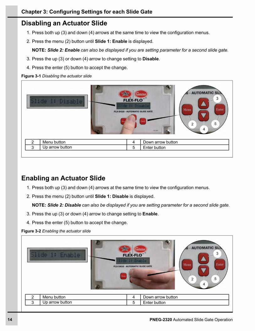
Disabling an Actuator Slide1. Press both up (3) and down (4) arrows at the same time to view the configuration menus.
2. Press the menu (2) button until Slide 1: Enable is displayed.
NOTE: Slide 2: Enable can also be displayed if you are setting parameter for a second slide gate.
3. Press the up (3) or down (4) arrow to change setting to Disable.
4. Press the enter (5) button to accept the change.
Figure 3-1 Disabling the actuator slide
2 Menu button 4 Down arrow button3 Up arrow button 5 Enter button
Enabling an Actuator Slide1. Press both up (3) and down (4) arrows at the same time to view the configuration menus.
2. Press the menu (2) button until Slide 1: Disable is displayed.
NOTE: Slide 2: Disable can also be displayed if you are setting parameter for a second slide gate.
3. Press the up (3) or down (4) arrow to change setting to Enable.
4. Press the enter (5) button to accept the change.
Figure 3-2 Enabling the actuator slide
2 Menu button 4 Down arrow button3 Up arrow button 5 Enter button
14 PNEG-2320 Automated Slide Gate Operation

Chapter 3: Configuring Settings for each Slide Gate
Setting the Manual Operation1. Press both up (3) and down (4) arrows at the same time to view the configuration menus.
2. Press the menu (2) button until Slide 1: Auto is displayed.
NOTE: Slide 2: Auto can also be displayed if you are setting parameter for a second slide gate.
3. Press the up (3) or down (4) arrow to change setting toManual.
4. Press the enter (5) button to accept the change.
Figure 3-3 Setting the manual operation
2 Menu button 4 Down arrow button3 Up arrow button 5 Enter button
Setting the Auto Operation1. Press both up (3) and down (4) arrows at the same time to view the configuration menus.
2. Press the menu (2) button until Slide 1: Manual is displayed.
NOTE: Slide 2: Manual can also be displayed if you are setting parameter for a second slide gate.
3. Press the up (3) or down (4) arrow to change setting to Auto.
4. Press the enter (5) button to accept the change.
5. Set the open position.
NOTE: The open position is a percentage of the full open position and available only in auto mode.
Figure 3-4 Setting the auto operation
2 Menu button 4 Down arrow button3 Up arrow button 5 Enter button
PNEG-2320 Automated Slide Gate Operation 15

Chapter 3: Configuring Settings for each Slide Gate
Setting the Open Position1. After selecting auto mode, the Open Pos 1: 100% will display.
NOTE: The default open position percentage is 100%.
2. Press the up (3) or down (4) arrows to change percentage setting.
3. Press the enter (5) button to accept the change.
Figure 3-5 Setting the open position
2 Menu button 4 Down arrow button3 Up arrow button 5 Enter button
Calibration1. During a calibration, the controller will slide the gate open until it no longer moves (no sensor signals
indicating movement).
2. The controller will then close the gate and count the number of positions until it reaches the closedposition (no sensor signals).
3. It will then report to the user the length of travel of the slide gate.
a. Initiate Calibration
i. A calibration can be started by either of the following methods:
• Switch control from Manual Mode to Auto Mode.
• Explicitly start a calibration from the calibration menu.
ii. Both methods can only be initiated from the local control board so that the user can observeand confirm the operation.
b. Calibration Length
i. When the calibration has completed, the distance traveled in inches will be displayed.
ii. The user must press confirm the distance by pressing a button.
16 PNEG-2320 Automated Slide Gate Operation
Chapter 3: Configuring Settings for each Slide Gate
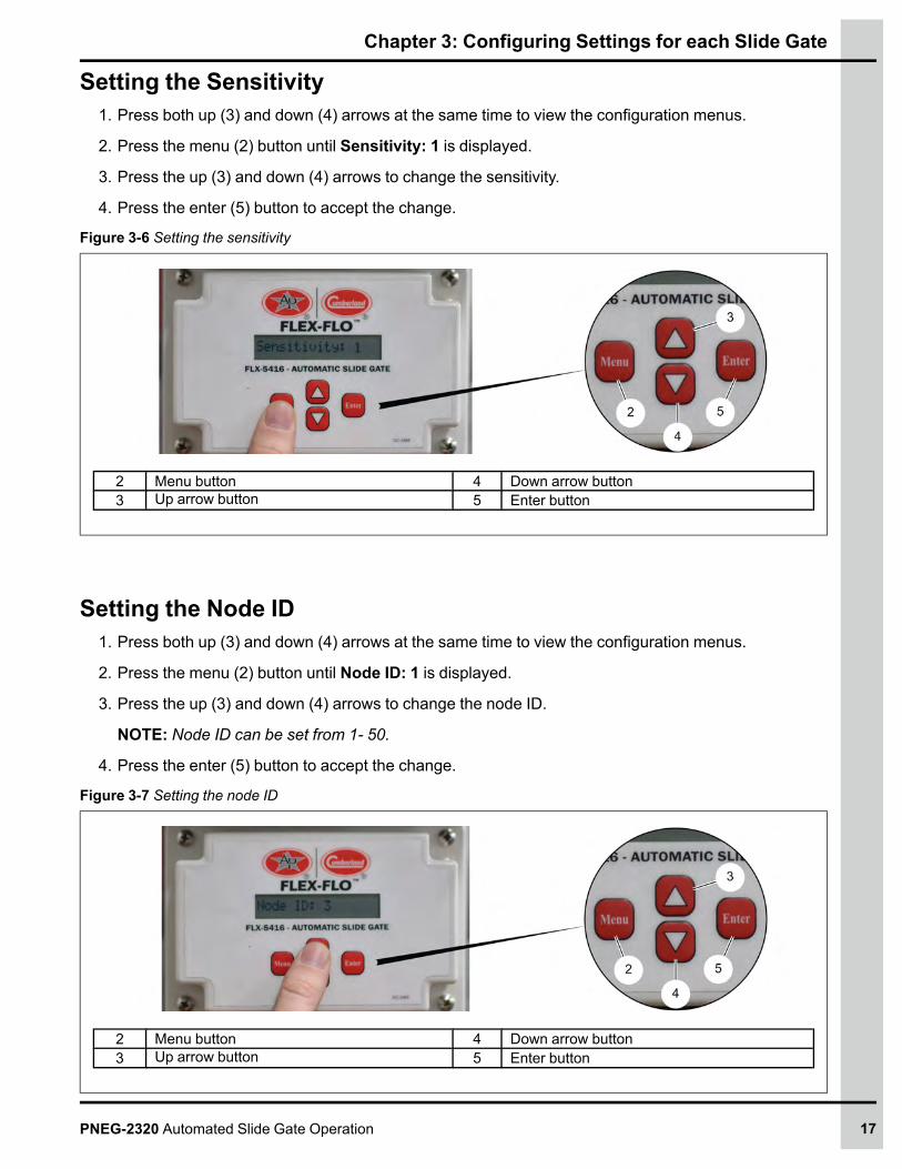
Setting the Sensitivity1. Press both up (3) and down (4) arrows at the same time to view the configuration menus.
2. Press the menu (2) button until Sensitivity: 1 is displayed.
3. Press the up (3) and down (4) arrows to change the sensitivity.
4. Press the enter (5) button to accept the change.
Figure 3-6 Setting the sensitivity
2 Menu button 4 Down arrow button3 Up arrow button 5 Enter button
Setting the Node ID1. Press both up (3) and down (4) arrows at the same time to view the configuration menus.
2. Press the menu (2) button until Node ID: 1 is displayed.
3. Press the up (3) and down (4) arrows to change the node ID.
NOTE: Node ID can be set from 1- 50.
4. Press the enter (5) button to accept the change.
Figure 3-7 Setting the node ID
2 Menu button 4 Down arrow button3 Up arrow button 5 Enter button
PNEG-2320 Automated Slide Gate Operation 17

Chapter 3: Configuring Settings for each Slide Gate
Clearing an AlarmNOTE: This menu appears ONLY if an alarm is present. The display will read “Clear Alarms: Y”.
Press the enter (5) button to clear the alarm.
Figure 3-8 Clearing the alarm
5 Enter button
18 PNEG-2320 Automated Slide Gate Operation
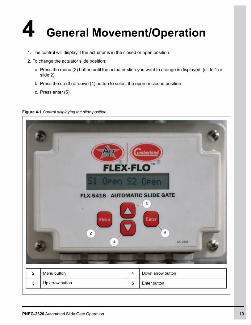
4 General Movement/Operation1. The control will display if the actuator is in the closed or open position.
2. To change the actuator slide position:
a. Press the menu (2) button until the actuator slide you want to change is displayed, (slide 1 orslide 2).
b. Press the up (3) or down (4) button to select the open or closed position.
c. Press enter (5).
Figure 4-1 Control displaying the slide position
2 Menu button 4 Down arrow button
3 Up arrow button 5 Enter button
PNEG-2320 Automated Slide Gate Operation 19

NOTES
20 PNEG-2320 Automated Slide Gate Operation
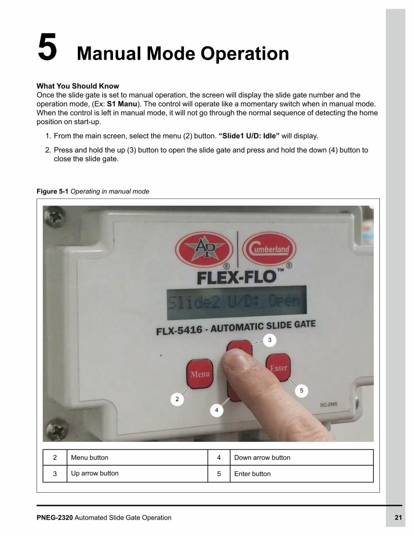
5 Manual Mode OperationWhat You Should KnowOnce the slide gate is set to manual operation, the screen will display the slide gate number and theoperation mode, (Ex: S1 Manu). The control will operate like a momentary switch when in manual mode.When the control is left in manual mode, it will not go through the normal sequence of detecting the homeposition on start-up.
1. From the main screen, select the menu (2) button. “Slide1 U/D: Idle” will display.
2. Press and hold the up (3) button to open the slide gate and press and hold the down (4) button toclose the slide gate.
Figure 5-1 Operating in manual mode
2 Menu button 4 Down arrow button
3 Up arrow button 5 Enter button
PNEG-2320 Automated Slide Gate Operation 21

NOTES
22 PNEG-2320 Automated Slide Gate Operation

6 Slide Gate Operation using theSite Controller (FLX-5419)
1. This control is generally located in a control house and can control up to eight local controllers(FLX-5416) on the bins. The home screen will display all the slides gates that are connected,flashing each one as it rotates through them. The screen will show the node and the slide numberand their positions. For example, “Slide 1.2: Close” would mean slide gate 2 on node 1 is closed.
Figure 6-1 Site controller displaying node and slide numbers
2. To change the position of a slide gate, you can press menu to go to the slide you want to change orwait until it flashes on the display. Then use the arrows to select open or closed and press enter toaccept the changes.
PNEG-2320 Automated Slide Gate Operation 23

Chapter 6: Slide Gate Operation using the Site Controller (FLX-5419)
Configuration Menus1. Asks if you want to scan the network to see if any new nodes have been added. Select Y for yes or
N for no.
Figure 6-2 Site controller requesting network scan
2. You can also set the operation mode (auto or manual) and the open position for the auto mode.
3. If you change the mode to manual, you will not be able to operate it from the main controller. Thedisplay will show the slide gate node ID and “Ovrd”. Manual operation can only take place at theslide gate controller at the bin. The steps for changing the configuration settings are the same as onthe local controller.
Figure 6-3 Setting the operation modes with site controller
24 PNEG-2320 Automated Slide Gate Operation
7 TroubleshootingTopics Covered in this Chapter
▪ Clearing an Obstruction▪ Alarms
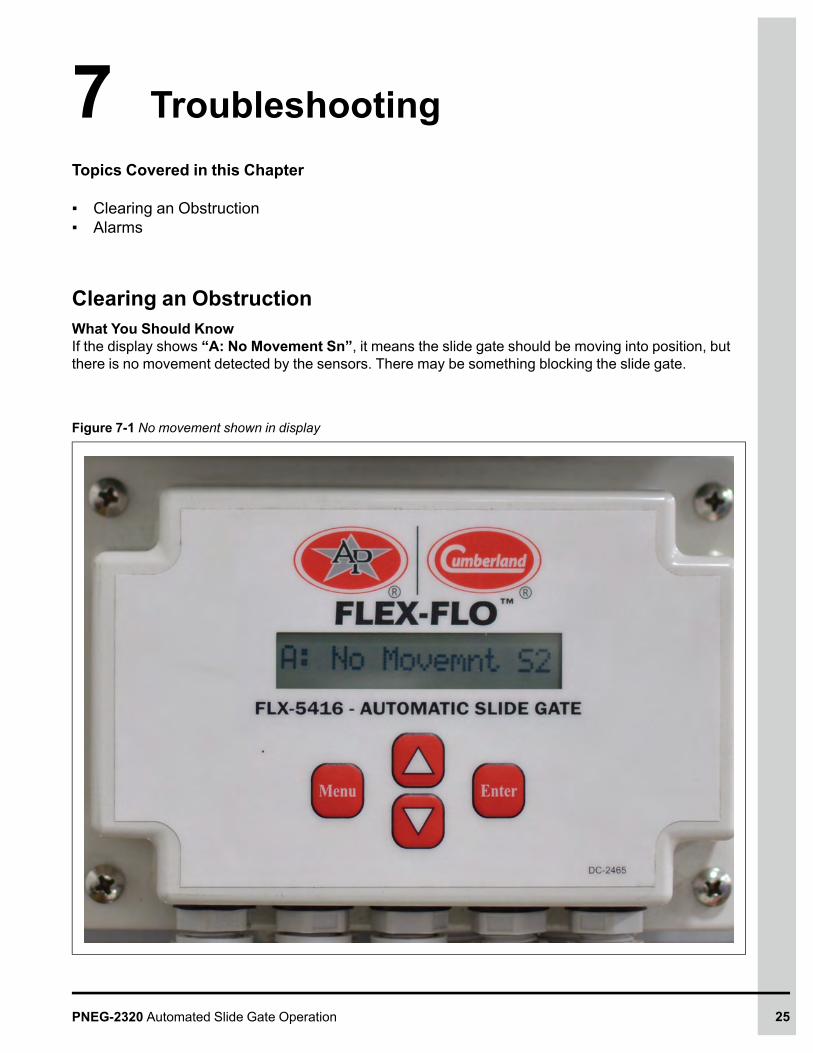
Clearing an ObstructionWhat You Should KnowIf the display shows “A: No Movement Sn”, it means the slide gate should be moving into position, butthere is no movement detected by the sensors. There may be something blocking the slide gate.
Figure 7-1 No movement shown in display
PNEG-2320 Automated Slide Gate Operation 25

Chapter 7: Troubleshooting
To Clear an Obstruction:
1. Physically go to the local controller at the bin.
2. Press both up and down arrows at the same time to view the configuration menus.
3. Press themenu button until the slide that has the error is displayed.
4. Change the operation mode tomanual and press enter.
5. Press and hold the up arrow to open the slide gate to remove the obstruction. This may release theobject that was jammed or you may need to clear the obstruction from the bin hopper or boot.
DANGER
Make sure to follow all safety precautions from the bin manufacturer if thisneeds to be done.
6. Press both up and down arrows at the same time to view the configuration menus.
7. Press themenu button until the slide that has the error is displayed.
8. Change the operation mode to auto and press enter. The control will calibrate the slide gate, whichwill clear the alarm.
Alarms1. Movement not Detected: Occurs when the motor is enabled, but the controller does not detect
movement.
2. Movement Detected: This alarm occurs when the motor is not enabled, but the controller doesdetect movement.
3. Wiring Alarm: This alarm occurs when the motor is enabled, but the slide is moving in the wrongdirection.
4. (Warning) Calibration Required: This warning alarm occurs when the motor is enabled, but thecontroller does not detect any movement. The inside tolerance controller will work normally.
26 PNEG-2320 Automated Slide Gate Operation

Chapter 7: Troubleshooting
Limited Warranty - Protein ProductsThe GSI Group, LLC. (“GSI”) warrants products which it manufactures, to be free of defects in materialsand workmanship under normal usage and conditions for a period of 12 months from the date of purchase(or, if shipped by vessel, 14 months from the date of arrival at the port of discharge). If, in GSI’s solejudgment, a product is found to have a defect in materials and/or workmanship, GSI will, at its own optionand expense, repair or replace the product or refund the purchase price. This Limited Warranty is subjectto extension and other terms as set forth below.Warranty Enhancements: The warranty period for the following products is enhanced as shown below and is inlieu of (and not in addition to) the above stated warranty period.
Product Warranty Period
AP® Fans Performer Series Direct Drive Fan Motor 3 Years
AP® and Cumberland® Flex-Flo/Pan Feeding System Motors 2 Years
Electronic Controls All Protein controls manufactured by GSI 24 Months from datecode on part
Cumberland®Feeding and WateringSystems
Feeder System Pan Assemblies 5 Years, prorated **
Feed Tubes (1.75" and 2.00") 10 Years, prorated *
Centerless Augers 10 Years, prorated *
Watering Nipples 10 Years, prorated *
* Warranty prorated from materiallist price:0 to 3 years - no material cost toend user3 to 5 years - end user pays 25%5 to 7 years - end user pays 50%7 to 10 years - end user pays 75%
** Warranty prorated from materiallist price:0 to 3 years - no material cost toend user3 to 5 years - end user pays 75%
Conditions and Limitations:THERE ARE NOWARRANTIES THAT EXTEND BEYOND THE LIMITED WARRANTY DESCRIPTION SET FORTHHEREIN; SPECIFICALLY, GSI DISCLAIMS ANYAND ALL OTHERWARRANTIES OFANY KIND, EXPRESS ORIMPLIED, INCLUDING, WITHOUT LIMITATION, WARRANTIES OF MERCHANTABILITY OR FITNESS FOR APARTICULAR PURPOSE OR USE IN CONNECTION WITH: (I) ANY PRODUCT MANUFACTURED OR SOLD BY GSI,OR (II) ANYADVICE, INSTRUCTION, RECOMMENDATION OR SUGGESTION PROVIDED BYAN AGENT,REPRESENTATIVE OR EMPLOYEE OF GSI REGARDING OR RELATED TO THE CONFIGURATION, INSTALLATION,LAYOUT, SUITABILITY FOR A PARTICULAR PURPOSE, OR DESIGN OF SUCH PRODUCTS.
The sole and exclusive remedy for any claimant is set forth in this Limited Warranty and shall not exceed the amount paidfor the product purchased. This Warranty only covers the value of the warranted parts and equipment, and does not coverlabor charges for removing or installing defective parts, shipping charges with respect to such parts, any applicable salesor other taxes, or any other charges or expenses not specified in this Warranty. GSI shall not be liable for any other direct,indirect, incidental or consequential damages, including, without limitation, loss of anticipated profits or benefits. Expensesincurred by or on behalf of a claimant without prior written authorization from the GSI warranty department shall not bereimbursed. This warranty is not transferable and applies only to the original end user. GSI shall have no obligation orresponsibility for any representations or warranties made by or on behalf of any dealer, agent or distributor. Prior toinstallation, the end user bears all responsibility to comply with federal, state and local codes which apply to the locationand installation of the products.
This Limited Warranty extends solely to products sold by GSI and does not cover any parts, components or materialsused in conjunction with the product, that are not sold by GSI. GSI assumes no responsibility for claims resulting fromconstruction defects, unauthorized modifications, corrosion or other cosmetic issues caused by storage, application orenvironmental conditions. Modifications to products not specifically delineated in the manual accompanying the product atinitial sale will void all warranties. This Limited Warranty shall not extend to products or parts which have been damagedby negligent use, misuse, alteration, accident or which have been improperly/inadequately maintained.
Service Parts:GSI warrants, subject to all other conditions described in this Warranty, Service Parts which it manufactures for a period of12 months from the date of purchase, unless specified in Enhancements above. Parts not manufactured by GSI will carrythe Manufacturer’s Warranty.(Protein Limited Warranty_REV01_ 06 November 2018)
PNEG-2320 Automated Slide Gate Operation 27
This equipment shall be installed in accordance withthe current installation codes and applicable
regulationswhich should be carefully followed in allcases. Authorities having jurisdiction should be
consulted before installations are made.
1004 E. Illinois St.Assumption, IL 62510-0020Phone: 1-217-226-4421Fax: 1-217-226-4420
www.automatedproduction.com / www.cumberlandpoultry.com
Copyright © 2020 by The GSI Group, LLCPrinted in the USACN #359984
Related Documents