Pseudo noise sequences tor engineers by R.N. Mutagi Pseudo noise (PN) sequences are widely used in digital communications and the theory involved has been treated extensively in the literature. However, a practising engineer is interested in the fundamentals and the applications of Phl sequences, and the methods of generating them with hardware. This paper presents, without the mathematical rigours, some of the interesting characteristics and the use of these characteristics in the generation and acquisition of PN sequences. The aeries-parallel method of generating PN sequences at high speeds with low-speed devices, which is of interest to hardware designers, is discussed. Some applications of PN sequences in communications and instrumentation are discussed. 1 Introduction Pseudo random binary sequences (PRBSs), also known as pseudo noise (F“), linear feedback shift register (LFSR) sequences or maximal length binary sequences (m- sequences), are widely used in digital communications. In a truly random sequence the bit pattern never repeats. However, generation of such a sequence is difficult and, more importantly, such a sequence has little use in practical systems. Applications demand that the data appear random to the channel but be predictable to the user. This is where the PRBS becomes useful. A pseudo random binary sequence is a semi-random sequence in the sense that it appears random within the sequence length, fulfillingthe needs of randomness, but the entire sequence repeats indefinitely. To a casual observer the sequence appears totally random, however to a user who is aware of the way the sequence is generated all its properties are known. PN sequences have several interesting properties, which are exploited in a variety of applications. Because of their good autocorrelation two similar PN sequences can easily be phase synchronised, even when one of them is corrupted by noise. A PN sequence is an ideal test signal, as it simulates the random Characteristics of a digital signal and can be easily generated. An exhaustive mathematical treatment is available in Reference 1. This paper describes some interesting properties, methods of generation, including the series-parallel method for high-speed generation, and some applications of PN sequences. 2 Properties of PN sequences A PN sequence is a bit stream of ‘1’s and ‘0’s occurring randomly, or almost randomly, with some unique properties. These properties are used in digital communications, instrumentation and measurements. The sequence serves as a reference pattern with known random characteristics for the analysis, optimisation and performance measurement of communication channels and systems. Run length In a PN sequence of any length the numbers of ‘1’s and ‘0’s differ only by one, i.e. the number of ‘1’s is just one more than the number of ‘0’s. For example, the PN sequence of length 15 (=[24 - 11) contains eight ‘1’s and seven ‘0’s. Asequence of consecutive ‘l’s, or ‘O’s, is called a ‘run’and the number of ‘1’s and ‘0’s is the run length. A PN sequence of length 2N- 1 contains one run of N‘l’s, and one run of N- 1 ‘0’s. The number of other runs, N- 2 to 1, of ‘1’s and ‘0’s increases as the power of 2, as shown in Table 1. The carrier and clock recovery circuits in a digital communication system have pattern-dependent behaviour and hence their performance can be evaluated using long PN sequences providing long runs of ‘1’s and ‘0’s. Table 1: lengths in a PN sequence of length 2N- 1 Number of runs of ‘1’s and ‘0‘s of various gth ‘1 N 1 0 N-I 0 1 N-2 1 1 N-3 2 2 N-4 4 4 2 1 2N-4 2N -4 2N-3 zN-3 ELECTRONICS & COMMUNICATION ENGINEERING JOURNAL APRIL 1996 79

Welcome message from author
This document is posted to help you gain knowledge. Please leave a comment to let me know what you think about it! Share it to your friends and learn new things together.
Transcript
Pseudo noise sequences tor engineers
by R.N. Mutagi
Pseudo noise (PN) sequences are widely used in digital communications and the theory involved has been treated extensively in the literature. However, a practising engineer is interested in the fundamentals and the applications of
Phl sequences, and the methods of generating them with hardware. This paper presents, without the mathematical rigours, some of the interesting characteristics and the use of these characteristics in the
generation and acquisition of PN sequences. The aeries-parallel method of generating PN sequences a t high speeds with low-speed devices, which is of interest to hardware designers, is discussed. Some applications of PN
sequences in communications and instrumentation are discussed.
1 Introduction
Pseudo random binary sequences (PRBSs), also known as pseudo noise (F“), linear feedback shift register (LFSR) sequences or maximal length binary sequences (m- sequences), are widely used in digital communications. In a truly random sequence the bit pattern never repeats. However, generation of such a sequence is difficult and, more importantly, such a sequence has little use in practical systems. Applications demand that the data appear random to the channel but be predictable to the user. This is where the PRBS becomes useful. A pseudo random binary sequence is a semi-random sequence in the sense that it appears random within the sequence length, fulfilling the needs of randomness, but the entire sequence repeats indefinitely. To a casual observer the sequence appears totally random, however to a user who is aware of the way the sequence is generated all its properties are known. PN sequences have several interesting properties, which are exploited in a variety of applications. Because of their good autocorrelation two similar PN sequences can easily be phase synchronised, even when one of them is corrupted by noise. A PN sequence is an ideal test signal, as it simulates the random Characteristics of a digital signal and can be easily generated. An exhaustive mathematical treatment is available in Reference 1. This paper describes some interesting properties, methods of generation, including the series-parallel method for high-speed generation, and some applications of PN sequences.
2 Properties of PN sequences
A PN sequence is a bit stream of ‘1’s and ‘0’s occurring randomly, or almost randomly, with some unique
properties. These properties are used in digital communications, instrumentation and measurements. The sequence serves as a reference pattern with known random characteristics for the analysis, optimisation and performance measurement of communication channels and systems.
Run length In a PN sequence of any length the numbers of ‘1’s and
‘0’s differ only by one, i.e. the number of ‘1’s is just one more than the number of ‘0’s. For example, the PN sequence of length 15 (=[24 - 11) contains eight ‘1’s and seven ‘0’s. Asequence of consecutive ‘l’s, or ‘O’s, is called a ‘run’ and the number of ‘1’s and ‘0’s is the run length. A PN sequence of length 2N- 1 contains one run of N‘l’s, and one run of N - 1 ‘0’s. The number of other runs, N- 2 to 1, of ‘1’s and ‘0’s increases as the power of 2, as shown in Table 1.
The carrier and clock recovery circuits in a digital communication system have pattern-dependent behaviour and hence their performance can be evaluated using long PN sequences providing long runs of ‘1’s and ‘0’s.
Table 1: lengths in a PN sequence of length 2N- 1
Number of runs of ‘1’s and ‘0‘s of various
gth ‘1
N 1 0 N - I 0 1 N - 2 1 1 N - 3 2 2 N - 4 4 4
2 1
2N-4 2 N - 4
2 N - 3 z N - 3
ELECTRONICS & COMMUNICATION ENGINEERING JOURNAL APRIL 1996 79
R N Mutagi received a BE degree in Tele-com- munications Engineering from Karnatak University in 1971 and a DIISc degi ee in Electronics Design Techno-logy from the Indian Institute of Science, Bangalore in 1976 He joined the Electronics Systems Division of the Indian Space Research Organi- zation at Ahmedabad in 1972 In 1976 he joined the Digital Communi-cation Division of the Space Applications Centre (SAC) where he was involved with the first Indian experi- mental communication satellite, APPLE. He became Head of the Speech Processing Section at SAC in 1985 and developed digital speech interpolation equipment, an echo canceller, a speech pat- tern analyser, an ADPCM transcoder and low-rate speech coders. Since 1991 he has been Head of the Baseband Processing Division at SAC. His current interests are in digital communica- tions, digital video and digital signal processing. He also teaches ‘Satellite communications’ and Digital signal processing’ to undergraduate classes.
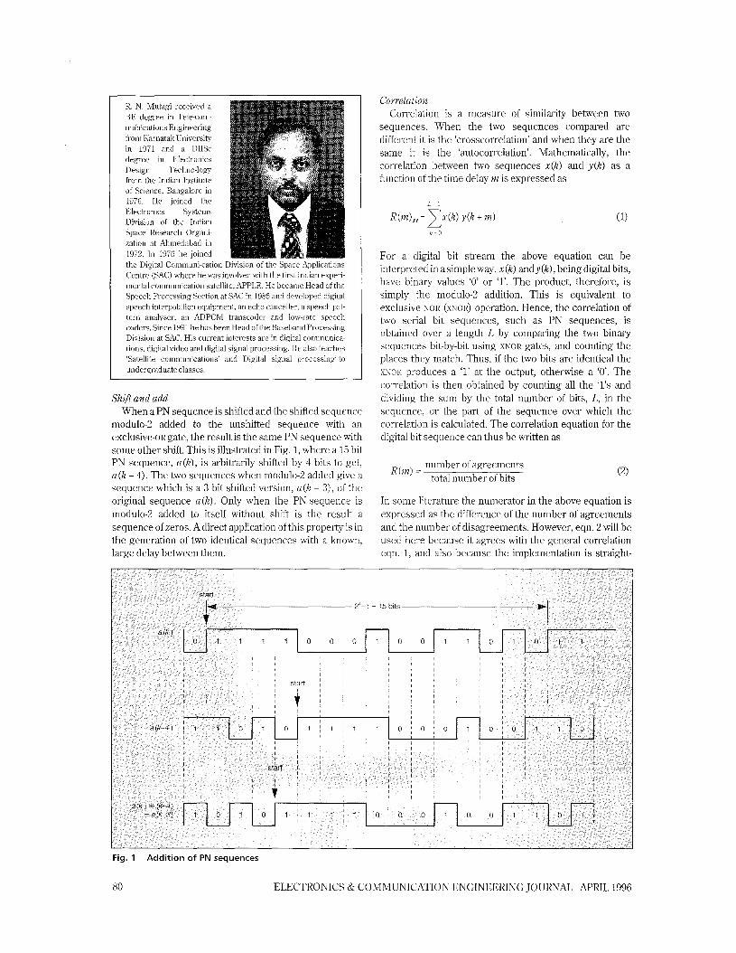
S h f l and add When a PN sequence is shifted and the shifted sequence
modulo-2 added to the unshifted sequence with an exclusive-OR gate, the result is the same PN sequence with some other shift. This is illustrated in Fig. 1, where a 15 bit PN sequence, a@), is arbitrarily shifted by 4 bits to get, a (k - 4). The two sequences when modulo-2 added give a sequence which is a 3 bit shifted version, a (h - 3), of the original sequence a@). Only when the PN sequence is modulo-2 added to itself without shift is the result a sequence of zeros. A direct application of this property is in the generation of two identical sequences with a known, large delay between them.
Correlation Correlation is a measure of similarity between two
sequences. When the two sequences compared are different it is the ‘crosscorrelation’ and when they are the same it is the ‘autocorrelation’. Mathematically, the correlation between two sequences x(k) and y ( k ) as a function of the time delay m is expressed as
For a digital bit stream the above equation can be interpreted in a simple way. x ( k ) andy(k), being digital bits, have binary values ‘0’ or ‘1’. The product, therefore, is simply the modulo-2 addition. This is equivalent to exclusive NOR ( ~ I O R ) operation. Hence, the correlation of two serial bit sequences, such as PN sequences, is obtained over a length L by comparing the two binary sequences bit-by-bit using XNOR gates, and counting the places they match. Thus, if the two bits are identical the XUOR produces a ‘1’ at the output, otherwise a ‘0’. The correlation is then obtained by counting all the ‘1’s and dividing the sum by the total number of bits, L, in the sequence, or the part of the sequence over which the correlation is calculated. The correlation equation for the digital bit sequence can thus be written as
number of agreements total number of bits
R(m) =
In some literature the numerator in the above equation is expressed as the difference of the number of agreements and the number of disagreements. However, eqn. 2 will be used here because it agrees with the general correlation eqn. 1, and also because the implementation is straight-
Fig. 1
80
Addition of PN sequences
ELECTRONICS & COMMUNICATION ENGINEERING JOURNAL APRIL 1996
forward as there is no need to form the difference of two sums. The difference in the results using the two definitions is only in the bias obtained in the correlation for all time lags m, where m + 0.
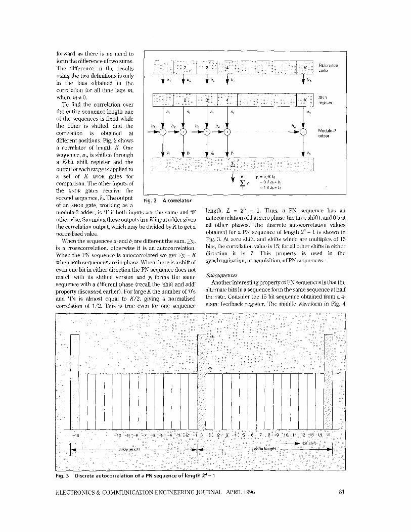
To find the correlation over the entire sequence length one of the sequences is fixed while the other is shifted, and the correlation is obtained at different positions. Fig. 2 shows a correlator of length K. One sequence, a,, is shifted through a K-bit shift register and the output of each stage is applied to a set of K XNOR gates for comparison. The other inputs of the XNOR gates receive the second sequence, b,. The output of an XNOR gate, working as a
Reference code
Shift register
f Yl f Y2 + Y3 + Y4 + Y K
y, = a, 0 b, + y, = 0 if a,# b, 1 = 1 if a, = b,
Fig. 2 A correlator
modulo-2 adder, is ‘1’ if both inputs are the same and ‘0’ otherwise. Summing these outputs in aK-input adder gives the correlation output, which may be divided by K to get a normalised value.
When the sequences a, and b, are different the sum, Zy,, is a crosscorrelation, otherwise it is an autocorrelation. When the PN sequence is autocorrelated we get Zy, = K when both sequences are in-phase. When there is a shift of even one bit in either direction the PN sequence does not match with its shifted version and yc forms the same sequence with a different phase (recall the ‘shift and add’ property discussled earlier). For large K the number of ‘0’s and ‘1’s is almost equal to K/2, giving a normalised correlation of 1/2. This is true even for one sequence
length, L = Z N - 1. Thus, a PN sequence has an autocorrelation of 1 at zero phase (no time shift), and 0.5 at all other phases. The discrete autocorrelation values obtained for a PN sequence of length 24 - 1 is shown in Fig. 3. At zero shift, and shifts which are multiples of 15 bits, the correlation value is 15; for all other shifts in either direction it is 7. This property is used in the synchronisation, or acquisition, of PN sequences.
Subsequences Another interesting property of PN sequences is that the
alternate bits in a sequence form the same sequence at half the rate. Consider the 15 bit sequence obtained from a 4- stage feedback register. The middle waveform in Fig. 4
Fig. 3
ELECTRONICS & COMMUNICATION ENGINEERING JOURNAL APRIL 1996
Discrete autocorrelation of a PN sequence of length z4 - 1
81
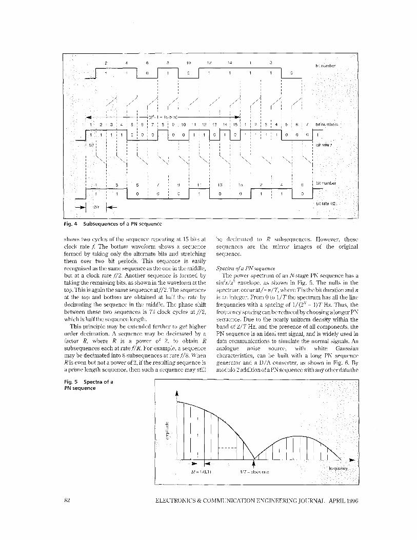
Fig. 4 Subsequences of a PN sequence
shows two cycles of the sequence repeating at 15 bits at clock rate f: The bottom waveform shows a sequence formed by taking only the alternate bits and stretching them over two bit periods. This sequence is easily recognised as the same sequence as the one in the middle, but at a clock rate f / 2 . Another sequence is formed by taking the remaining bits, as shown in the waveform at the top. This is again the same sequence at f / 2 . The sequences at the top and bottom are obtained at half the rate by decimating the sequence in the middle. The phase shdt between these two sequences is 7% clock cycles at f/2, which is half the sequence length.
This principle may be extended further to get higher order decimation. A sequence may be decimated by a factor R, where R is a power of 2, to obtain R subsequences each at rate f /R . For example, a sequence may be decimated into 8 subsequences at rate f / 8 . When R is even but not a power of 2, if the resulting sequence is a prime length sequence, then such a sequence may still
PN sequence
be decimated to R subsequences. However, these sequences are the mirror images of the original sequence.
Spectra ofa PNsequence The power spectrum of an N-stage PN sequence has a
sinf/x" envelope, as shown in Fig. 5. The nulls in the spectrum occur at f = n/T, where Tis the bit duration and n is an integer. From 0 to 1/T the spectrum has all the line frequencies with a spacing of 1/ (aN - 1) T Hz. Thus, the frequency spacing can be reduced by choosing a longer PN sequence. Due to the nearly uniform density within the band of 2/T Hz, and the presence of all components, the PN sequence is an ideal test signal, and is widely used in data communications to simulate the normal signals. An analogue noise source, with white Gaussian characteristics, can be built with a long PN sequence generator and a D/A converter, as shown in Fig. 6. By modulo-2 addition of a PN sequence with any other data the
Fig. 5 Spectra of a
82 ELECTRONICS & COMMUNICATION ENGINEEIUNG JOURNAL APRIL 1996
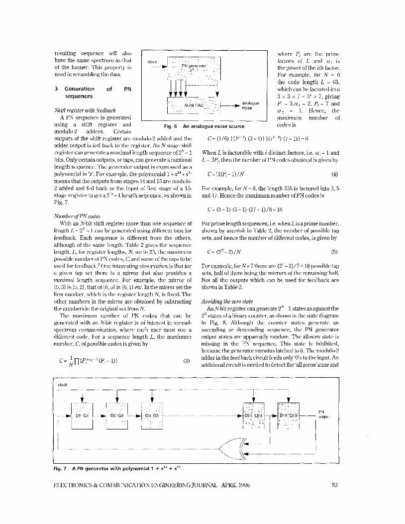
resulting sequence will also have the same spectrum as that of the former. This property is used in scramblin,g the data.
3 Generation of PN sequences
Sh ifi register with ,feedback A PN sequence is generated
using a shift register and modulo-2 adders. Certain
CI
Fig. 6 An analogue noise source
outputs of the shift register are modulo-2 added and the adder output is fed back to the register. An N-stage shift register can generate a maximal length sequence of 2N- 1 bits. Only certain outputs, or taps, can generate amaximal length sequence. The generator output is expressed as a polynomial in 'x'. For example, the polynomial 1 + xI4 + x15
means that the outputs from stages 14 and 15 are modulo- 2 added and fed back to the input of first stage of a 15- stage register to get a 215 - 1 length sequence, as shown in Fig. 7.
NulnberofPN codes With an N-bit shift register more than one sequence of
length L = Z N - 1 can be generated using different taps for feedback. Each sequence is different from the others, although of the same length. Table 2 gives the sequence length, L, for register lengths, N, up to 25, the maximum possible number of PN codes, C, and some of the taps to be used for feedback2 One interesting observation is that for a given tap set there is a mirror that also provides a maximal length sequence. For example, the' mirror of {5,31 is {5,21, that of {6,51 is {6,11 etc. In the mirror set the first number, which is the register length N, is fixed. The other numbers in the mirror are obtained by subtracting the numbers in the original set from N.
The maximum number of PN codes that can be generated with an N-bit register is of interest in spread- spectrum communication, where each user must use a different code. For a sequence length L, the maximum number, C, of possible codes is given by
(3)
where Pi are the prime factors of L and ai is the power of the ith factor. For example, for N = 6 the code length L = 63, which can be factored into 3 x 3 x 7 = 3' x 7, giving Pl = 3,u1 = 2, P2= 7 and a 2 = 1. Hence, the maximum number of codes is
C = (1/6) {(3'-l) (3-1)) ((7l-l) (7-1)1=6
When L is factorable with i distinct factors, i.e. ai = 1 and L = rIPi, then the number of PN codes obtained is given by
For example, for N = 8, the length 255 is factored into 3 , 5 and 17. Hence the maximum number of PN codes is
C=(3-1) (5-1) (17-1)/8=16
For prime length sequences, i.e. when L is aprime number, shown by asterisk in Table 2, the number of possible tap sets, and hence the number of different codes, is given by
C= (2N-2)/N (5)
For example, for N = 7 there are (27 - 2) /7 = 18 possible tap sets, half of them being the mirrors of the remaining half. Not all the outputs which can be used for feedback are shown in Table 2.
Avoiding the zero state An N-bit register can generate 2N- 1 states as against the
2N states of a binary counter, as shown in the state diagram in Fig. 8. Although the counter states generate an ascending or descending sequence, the PN generator output states are apparently random. The all-zero state is missing in the IPN sequence. This state is inhibited, because the generator remains latched to it. The modulo-2 adder in the feedback circuit feeds only '0's to the input. An additional circuit is needed to detect the 'all zeros' state and
Fig. 7 A PN generator with polynomial 1 + x14 + XI'
ELECTRONICS & COMMUNICATION ENGINEERING JOURNAL APRIL 1996 83
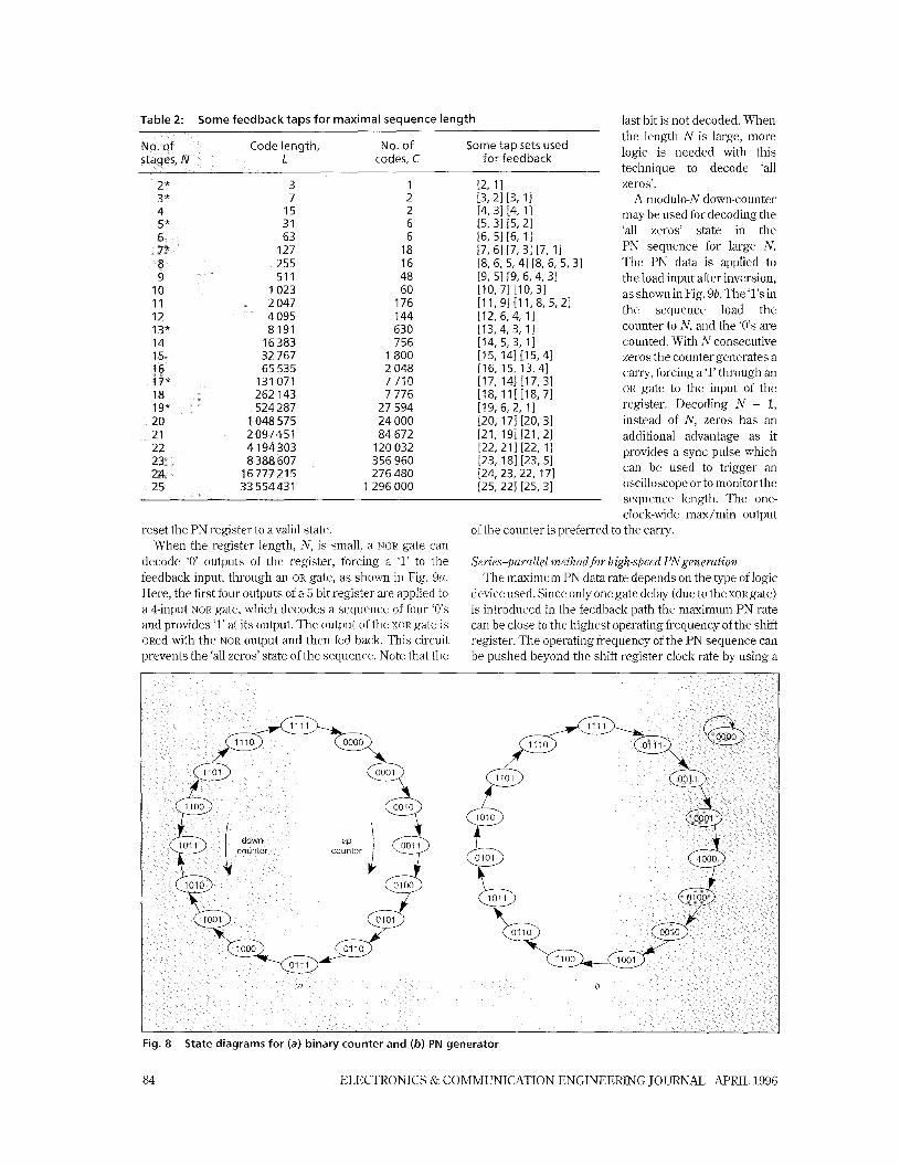
Table 2: Some feedback taps for maximal sequence length
Some tap sets used codes, C for feedback
2* 3 1 [2, 11 3* 7 2 [3,21 [3, 11 4 15 2 14,3114, 11
31 6 I5, 31 [5,21 63 6 [6, 51 [6, 11
127 18 17,61[7,31[7,11 255 16 [8, 6, 5,4l [8,6, 5,31 51 1 48 [9, 51 [9, 6,4,31
10 1023 60 [IO, 71 110, 31 11 2 047 176 [I 1, 91 I1 1,8, 5, 21 12 4 095 144 (12, 6 4 , 11 13” 8 191 630 [13,4, 3, 11 14 16383 756 114, 5, 3, 11
32 767 1800 [15, 141 [15,41 65 535 2 048 116, 15, 13,4]
131 071 7 710 [17, 141 [17,31 262 143 7 776 [18, 11[[18,71
19* 524 287 27 594 [19, 6 2 , 11 20 1 048 575 24 000 120, 171 [20,31 21 84 672 P I , 191 P I , 21
120 032 [22,211 [22, 11 8 388 607 356 960 [23, 181 [23,51
16777215 276 480 [24, 23, 22, 171 33 554431 1296000 125, 221 [25,31
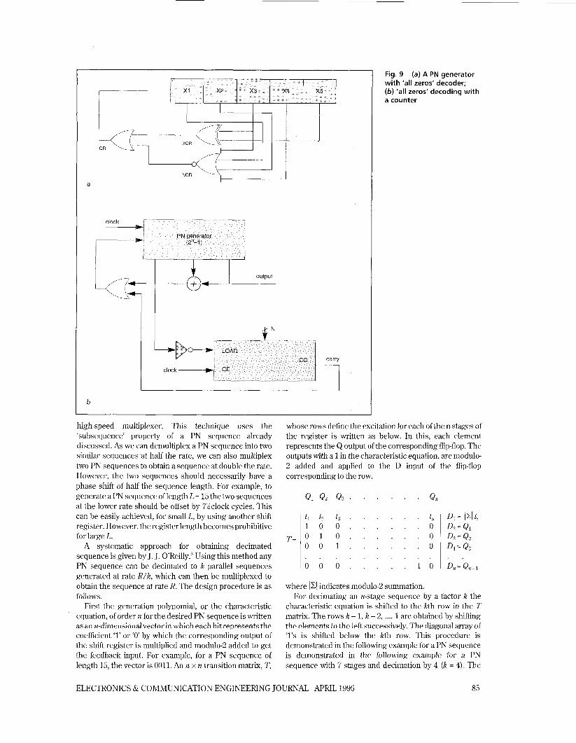
reset the PN register to a valid state. When the register length, N, is small, a NOR gate can
decode ‘0’ outputs of the register, forcing a ‘1’ to the feedback input, through an OR gate, as shown in Fig. 9a. Here, the first four outputs of a 5-bit register are applied to a 4-input NOR gate, which decodes a sequence of four ‘0’s and provides ‘1’ at its output. The output of the XOR gate is ORed with the NOR output and then fed back. This circuit prevents the ‘all zeros’ state of the sequence. Note that the
last bit is not decoded. When the length N is large, more logic is needed with this technique to decode ‘all zeros’.
A modulo-N down-counter may be used for decoding the ‘all zeros’ state in the PN sequence for large N. The PN data is applied to the load input after inversion, as shown in Fig. 9b. The ‘1’s in the sequence load the counter to N, and the ‘0’s are counted. With N consecutive zeros the counter generates a carry, forcing a ‘1’ through an OR gate to the input of the register. Decoding N - 1, instead of N, zeros has an additional advantage as it provides a sync pulse which can be used to trigger an oscilloscope or to monitor the sequence length. The one- clock-wide max/min output
of the counter is preferred to the carry.
Series-parallel method for high-speed PNgeneration The maximum PN data rate depends on the type of logic
device used. Since only one gate delay (due to the XORgate) is introduced in the feedback path the maximum PN rate can be close to the highest operating frequency of the shift register. The operating frequency of the PN sequence can be pushed beyond the shift register clock rate by using a
Fig. 8 State diagrams for (a) binary counter and (b) PN generator
84 ELECTRONICS & COMMUNICATION ENGINEERING JOURNAL APRIL 1996
output (b--J--
Fig. 9 with ‘all zeros’ decoder; (b) ’all zeros‘ decoding with a counter
(a) A PN generator
high-speed multiplexer. This technique uses the ‘subsequence’ property of a PN sequence already discussed. As we can demultiplex a PN sequence into two similar sequences at half the rate, we can also multiplex two PN sequences to obtain a sequence at double the rate. However, the twlo sequences should necessarily have a phase shift of half the sequence length. For example, to generate a PN sequence of length L = 15 the two sequences at the lower rate should be offset by 7Xclock cycles. This can be easily achieved, for small L, by using another shift register. However, the register length becomes prohibitive for large L.
A systematic approach for obtaining decimated sequence is given by J. J. O’Reilly.3 Using this method any PN sequence can be decimated to k parallel sequences generated at rate R/k, which can then be multiplexed to obtain the sequence at rate R. The design procedure is as follows.
First the generation polynomial, or the characteristic equation, of order n for the desired PN sequence is written as an n-dimensional vector in which each bit represents the coefficient ‘1’ or ‘0’ by which the corresponding output of the shift register is multiplied and modulo-2 added to get the feedback input. For example, for a PN sequence of length 15, the vector is 0011. An n x n transition matrix, T,
whose rows define the excitation for each of the n stages of the register is written as below. In this, each element represents the Q output of the corresponding flip-flop. The outputs with a 1 in the characteristic equation, are modulo- 2 added and applied to the D input of the flip-flop corresponding to the row.
. . . . . . . . . . 10 0 0 . . . . . 1 0 ID,=Q,l
where 1x1 indicates modulo-2 summation. For decimating an n-stage sequence by a factor k the
characteristic equation is shifted to the kth row in the T matrix. The rows k - 1, k - 2, .... 1 are obtained by shifting the elements to the left successively. The diagonal array of ‘1’s is shifted below the kth row. This procedure is demonstrated in the following example for a PN sequence is demonstrated in the following example for a PN sequence with 7 stages and decimation by 4 (k = 4). The
ELECTRONICS & COMMUNICATION ENGINEERING JOURNAL APRIL 1996 85
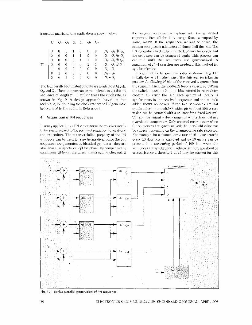
transition matrix for this application is shown below:
0 0 1 1 0 0 0 0 0 0 1 1 0 0 0 0 0 0 1 1 0 0 0 0 0 0 1 1 1 0 0 0 0 0 0 0 1 0 0 0 0 0 0 0 1 0 0 0 0
The four parallel decimated outputs are available at Qi, Q,, Qs, and Qq. These outputs can be multiplexed to get the PN sequence of length 27 - 1 at four times the clock rate, as shown in Fig.10. A design approach, based on this technique, for doubling the clock rate of the PN generator is described by the author in Reference 4.
4 Acquisition of PN sequences
In many applications a PN generator at the receiver needs to be synchronised to the received sequence generated at the transmitter. The autocorrelation property of the PN sequence can be used for synchronisation. Since the two sequences are generated by identical generators they are similar in all respects, except the phase. By comparing the sequences bit-by-bit the phase match can be checked. If
the received sequence is in-phase with the generated sequence, then all the bits, except those corrupted by noise, match. If the sequences are out of phase, the comparison gives a mismatch of almost half the bits. The PN generator can then be inhibited for one clock cycle and the sequence can be compared again. This process can continue until the sequences are synchronised. A maximum of 2”-1 searches are needed in this method for synchronisation.
Afaster method for synchronisation is shown in Fig. ll.5 Initially the switch at the input of the shift register is kept in position A, allowing N bits of the received sequence into the register. Then the feedback loop is closed by putting the switch in position B. If the bits entered in the register contain no error the sequence generated locally is synchronous to the received sequence and the modulo adder shows no errors. If the two sequences are not synchronised the modulo-2 adder gives about 50% errors which can be counted with a counter for a fixed interval. The counter output is then compared with a threshold in a magnitude comparator. Only channel errors occur when the sequences are synchronised; the threshold value can be chosen depending on the channel error rate expected. For example, for a channel error rate of 10- ’, one error in every 10 data bits is expected and so 10 errors can be present in a measuring period of 100 bits when the sequences are synchronised; otherwise there are about 50 errors. Hence a threshold of 25 may be chosen for this
Fig. 10
86
Series-parallel generation of PN sequence
ELECTRONICS & COMMUNICATION ENGINEERING JOURNAL APRIL 1996
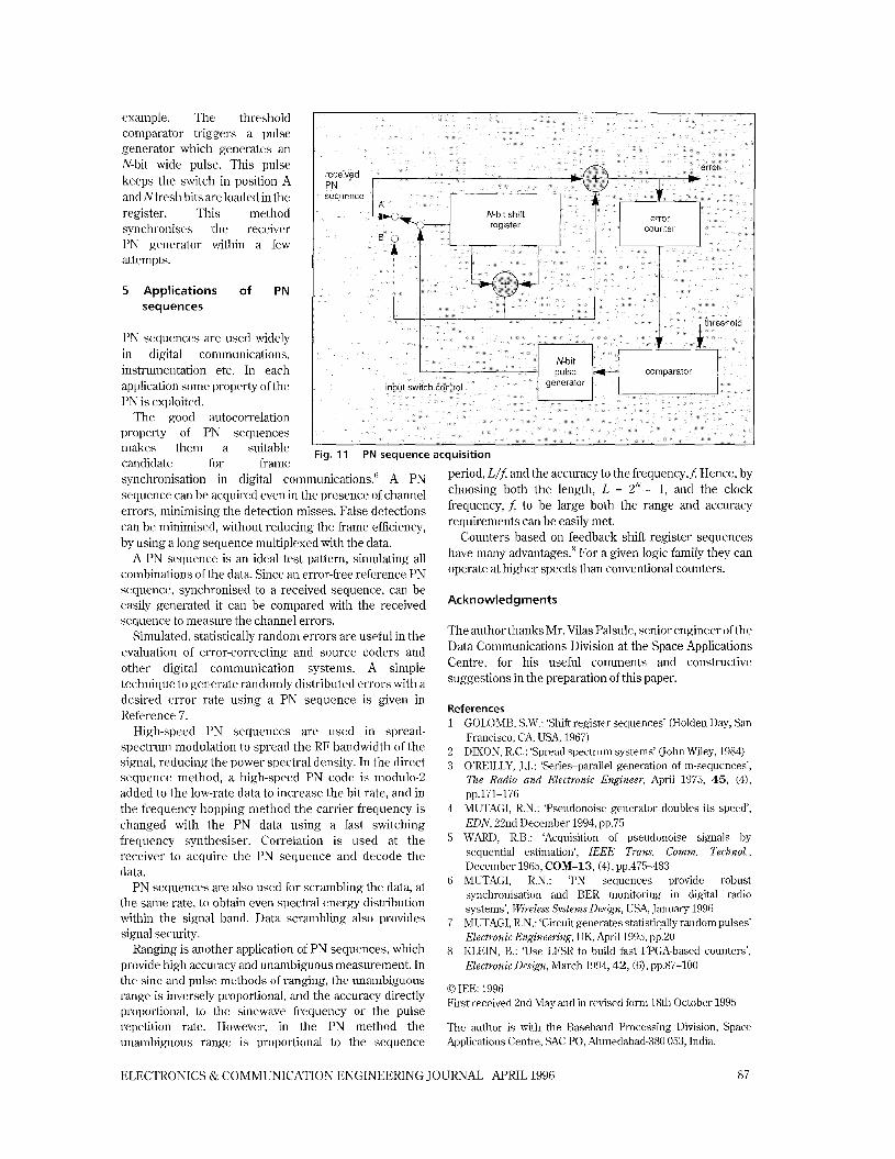
example. The threshold comparator triggers a pulse generator which generates an N-bit wide pulse. This pulse keeps the switch in position A and Nfresh bits are loaded in the register. This method synchronises the receiver PN generator within a few attempts.
5 Applications of PN sequences
PN sequences are used widely in digital communications, instrumentation etc. In each application some property of the PN is exploited.
The good autocorrelation property of PN sequences makes them a suitable candid ate for frame
Fig. 11 PN sequence acquisition
synchronisation in digital communications.6 A PN sequence can be acquired even in the presence of channel errors, minimising the detection misses. False detections can be minimised, without reducing the frame efficiency, by using a long sequence multiplexed with the data.
A PN sequence is an ideal test pattern, simulating all combinations off he data. Since an error-free reference PN sequence, synchronised to a received sequence, can be easily generated it can be compared with the received sequence to measure the channel errors.
Simulated, statistically random errors are useful in the evaluation of error-correcting and source coders and other digital communication systems. A simple technique to generate randomly distributed errors with a desired error rate using a PN sequence is given in Reference 7.
High-speed PN sequences are used in spread- spectrum modulation to spread the RF bandwidth of the signal, reducing the power spectral density. In the direct sequence method, a high-speed PN code is modulo-2 added to the low-rate data to increase the bit rate, and in the frequency-hopping method the carrier frequency is changed with the PN data using a fast switching frequency synthesiser. Correlation is used at the receiver to acquire the PN sequence and decode the data.
PN sequences are also used for scrambling the data, at the same rate, to obtain even spectral energy distribution within the signal band. Data scrambling also provides signal security.
Ranging is another application of PN sequences, which provide high accuracy and unambiguous measurement. In the sine and pulse methods of ranging, the unambiguous range is inversely proportional, and the accuracy directly proportional, to the sinewave frequency or the pulse repetition rate. However, in the PN method the unambiguous range is proportional to the sequence
period, L/f, and the accuracy to the frequencyJ Hence, by choosing both the length, L = ZN - 1, and the clock frequency, f, to be large both the range and accuracy requirements can be easily met.
Counters based on feedback shift register sequences have many advantages.8 For a given logic family they can operate at higher speeds than conventional counters.
Acknowledgments
The author thanks Mr. Vilas Palsule, senior engineer of the Data Communications Division at the Space Applications Centre, for his useful comments and constructive suggestions in the preparation of this paper.
References 1 GOLOME, S.W.: ‘Shift register sequences’ (Holden Day, San
Francisco, CA, USA, 1967) 2 DIXON, R.C.: ‘Spread spectrum systems’ (john Wiley, 1984) 3 O’REILLY, J.J.: ‘Series-parallel generation of m-sequences’,
The Radio and Electronic Engineer, April 1975, 45 , (4),
4 MUTAGI, R.N.: ‘Pseudonoise generator doubles its speed’, EDN, 22nd December 1994, pp.75
5 WARD, R.B.: ‘Acquisition of pseudonoise signals by sequential estimation’, IEEE Trans. Comm. Technol., December 1965, COM-13, (4), pp.475-483
6 MUTAGI, R.N.: ‘PN sequences provide robust synchronisation and BER monitoring in digital radio systems’, Wireless Systems Design, USA, January 1996
7 MUTAGI, R.N.: ‘Circuit generates statistically random pulses’ Electronic Engineering, UK, April 1995, pp.20
8 KLEIN, B.: ‘Use LFSR to build fast FPGA-based counters’, Electronic Design, March 1994,42, (6), pp.87-100
pp.171-176
0 IEE: 1996 First received 2nd May and in revised form 18th October 1995
The author is with the Baseband Processing Division, Space Applications Centre, SAC PO, Ahmedabad-380 053, India.
ELECTRONICS & COMMUNICATION ENGINEERING JOURNAL APRIL 1996 87
Related Documents