Address of Publisher & Editor's Office : GDAÑSK UNIVERSITY OF TECHNOLOGY Faculty of Ocean Engineering & Ship Technology ul. Narutowicza 11/12 80-952 Gdañsk, POLAND tel.: +48 58 347 17 93 fax : +48 58 341 47 12 e-mail : [email protected] Account number : BANK ZACHODNI WBK S.A. I Oddzia³ w Gdañsku 41 1090 1098 0000 0000 0901 5569 Editorial Staff : Witold Kirkor Editor in Chief e-mail : [email protected] Przemys³aw Wierzchowski Scientific Editor e-mail : [email protected] Maciej Paw³owski Editor for review matters e-mail : [email protected] Tadeusz Borzêcki Editor for international relations e-mail : [email protected] Cezary Spigarski Computer Design e-mail : [email protected] Domestic price : single issue : 20 z³ Prices for abroad : single issue : - in Europe US$ 15 - overseas US$ 20 ISSN 1233-2585 NA V AL ARCHITE CTURE 3 DARIUSZ BOROÑSKI , JANUSZ KOZAK Research on deformations of laser -welded joint of a steel sandwich structure model MARI NE ENGINEE RING 9 ANDRZEJ MIS ZCZAK Viscoelastic unsteady lubrication of radial slide journal bearing at imp ulsive motion 23 JANUSZ KOLENDA Fatigue safe-life criterion for metal element s under multiaxial constant and periodic loads UNDERWATER TECHNOLOGY 27 JERZY GARUS Kinematical control of motion of underwater vehicle in horizontal plane POLISH MARITIME RESEARCH in internet www.bg.pg.gda.pl/pmr.html Index and abstracts of the papers 1994 ÷ 2003 PUBLISHER : CONTENTS POLISH MARITIME RESEARCH No 2(40) 2004 Vol 11 The papers published in this issue have been reviewed by : Prof. J. Girtler , Prof. J. Lisowski, Prof. K. Rosochowicz, Prof. K. W ierzcholski, M. Sperski, Ass oc. Prof.

Welcome message from author
This document is posted to help you gain knowledge. Please leave a comment to let me know what you think about it! Share it to your friends and learn new things together.
Transcript

7/30/2019 PMRes_2004_2
http://slidepdf.com/reader/full/pmres20042 1/32
Address of Publisher
& Editor's Office :
GDAÑSK UNIVERSITYOF TECHNOLOGY
Facultyof Ocean Engineering
& Ship Technology
ul. Narutowicza 11/1280-952 Gdañsk, POLAND
tel.: +48 58 347 17 93fax : +48 58 341 47 12
e-mail : [email protected]
Account number :
BANK ZACHODNI WBK S.A.
I Oddzia³ w Gdañsku41 1090 1098 0000 0000 0901 5569
Editorial Staff :
Witold Kirkor Editor in Chief e-mail : [email protected]
Przemys³aw Wierzchowski Scientific Editor e-mail : [email protected]
Maciej Paw³owski Editor for review matterse-mail : [email protected]
Tadeusz Borzêcki Editor for international relationse-mail : [email protected]
Cezary Spigarski Computer Designe-mail : [email protected]
Domestic price :
single issue : 20 z³
Prices for abroad :
single issue :- in Europe US$ 15- overseas US$ 20
ISSN 1233-2585
NAVAL ARCHITECTURE 3 DARIUSZ BOROÑSKI, JANUSZ KOZAK
Research on deformations of laser-welded joint of a steel sandwich structure model
MARINE ENGINEERING
9 ANDRZEJ MISZCZAK Viscoelastic unsteady lubrication of radial slide
journal bearing at impulsive motion
23 JANUSZ KOLENDA Fatigue safe-life criterion for metal elementsunder multiaxial constant and periodic loads
UNDERWATER TECHNOLOGY
27 JERZY GARUS Kinematical control of motionof underwater vehicle in horizontal plane
POLISH
MARITIME
RESEARCH
in internet www.bg.pg.gda.pl/pmr.html
Index and abstractsof the papers1994 ÷ 2003
PUBLISHER :
CONTENTS
POLISH MARITIME RESEARCHNo 2(40) 2004 Vol 11
The papers published in this issue have been reviewed by :
Prof. J. Girtler, Prof. J. Lisowski, Prof. K. Rosochowicz, Prof. K. Wierzcholski, M. Sperski, Assoc. Prof.
7/30/2019 PMRes_2004_2
http://slidepdf.com/reader/full/pmres20042 2/32
2 POLISH MARITIME RESEARCH, No 4/2003
POLISH MARITIME RESEARCH is a scientific journal of worldwide circulation. The journal appears asa quarterly four times a year. The first issue of it was published in September 1994. Its main aim is to present original, innovative scientific ideas and Research & Development achievements in the field of :
Engineering, Computing & Technology, Mechanical Engineering,
which could find applications in the broad domain of maritime economy. Hence there are published paperswhich concern methods of the designing, manufacturing and operating processes of such technical objectsand devices as : ships, port equipment, ocean engineering units, underwater vehicles and equipment as wellas harbour facilities, with accounting for marine environment protection.The Editors of POLISH MARITIME RESEARCH make also efforts to present problems dealing witheducation of engineers and scientific and teaching personnel. As a rule, the basic papers are supplemented by information on conferences , important scientific events as well as cooperation in carrying out interna-tional scientific research projects.
Editorial
Editorial Board
Chairman : Prof. JERZY GIRTLER - Gdañsk University of Technology, Poland
Vice-chairman : Prof. ANTONI
JANKOWSKI
- Institute of Aeronautics, PolandVice-chairman : Prof. K RZYSZTOF K OSOWSKI - Gdañsk University of Technology, Poland
Prof. ANTONI ISKRA
Poznañ University of TechnologyPoland
Prof. YASUHIKO OHTA
Nagoya Institute of TechnologyJapan
Dr POUL ANDERSEN
Technical University of Denmark Denmark
Prof. JAN K ICIÑSKI
Institute of Fluid-Flow Machineryof PASciPoland
Prof. ANTONI K. OPPENHEIM
University of CaliforniaBerkeley, CA
USA
Dr MEHMET ATLAR
Universityof Newcastle
United Kingdom
Prof. K RZYSZTOF R OSOCHOWICZ
Gdañsk Universityof Technology
Poland
Prof. ZYGMUNT K ITOWSKI
Naval UniversityPoland
Prof. GÖRAN BARK
Chalmers Universityof Technology
Sweden
Prof. K LAUS SCHIER
University of Applied SciencesGermany
Prof. WAC£AW K OLLEK
Wroc³aw University of TechnologyPoland
Prof. MUSTAFA BAYHAN
Süleyman Demirel UniversityTurkey
Prof. ODD M. FALTINSEN
Norwegian Universityof Science and Technology
Norway
Prof. FREDERICK STERN
University of Iowa,IA, USA
Prof. NICOS LADOMMATOS
University CollegeLondon
United Kingdom
Prof. PATRICK V. FARRELL
University of WisconsinMadison, WI
USA
Prof. JÓZEF SZALA
Bydgoszcz Universityof Technology and Agriculture
Poland
Prof. JÓZEF LISOWSKI
Gdynia MaritimeUniversity
Poland
Prof. STANIS£AW GUCMA
Maritime Universityof Szczecin
Poland
Prof. JERZY MATUSIAK
Helsinki Universityof Technology
Finland
Prof. JAN SZANTYR
Gdañsk Universityof Technology
Poland
Prof. MIECZYS£AW HANN
Technical University of SzczecinPoland
Prof. EUGEN NEGRUS
University of BucharestRomania
Prof. BORIS A. TIKHOMIROV
State Marine Universityof St. Petersburg
Russia
Prof. DRACOS VASSALOS
University of Glasgow and StrathclydeUnited Kingdom
Prof. K RZYSZTOF WIERZCHOLSKI
Gdañsk University of TechnologyPoland
7/30/2019 PMRes_2004_2
http://slidepdf.com/reader/full/pmres20042 3/32
3POLISH MARITIME RESEARCH, No 2/2004
Research on deformations of laser-welded joint of a steel sandwich structure model
Dariusz Boroñski
Academy of Agriculture & Engineering, Bydgoszcz
Janusz Kozak
Gdañsk University of Technology
INTRODUCTION
Developments in novel joining techniques including laser,hybrid (laser MAG) and friction stir welding have brought
about their broader and broader industrial applications, as wellas they opened new possibilities for designers to create struc-tures not feasible so far.
Higher accuracy of so made welds and their more uniformquality, increased speed of welding, reduced amount of heatintroduced to weld zone, possible automation and use of ro- bots for welding processes these are some advantages deci-ding upon fast application of such techniques in space, aircraft,car or shipbuilding industries [1, 2, 3, 4, 5, 6].
Their special position in the case of the application e.g. inshipbuilding [7] or aircraft industry is associated with, a.o., the possibility of building the sandwich structures which consistof load-carrying shell platings stiffened by cores of various
forms, that leads, a.o., to a significant reduction of mass of designed objects. However application of the novel solutionsusually demands some changes to be introduced to the tradi-tional methods of construction of such objects as aircrafts andships.
One of the example solutions based on the laser weldingtechnique is a steel double-skin structure stiffened by internalwebs joined with the shell platings by using laser welding ap- plied from outside of the object under construction.
The idea of the replacement of the traditional single-skinship hull structure with a new thin double-skin structure whosesystem of basic stiffening members is installed in the space between the shell platings, was born in the 1950s, and then itwas studied by NASA [8, 9, 10]; however its practical applica-
tion was attempted by US Navy at the end of the 1980s [11].Presently Meyer Werft, Germany, applied the solution to thestructural panels which appeared ten times stiffer and weighingless by 35% than their conventional equivalents [12].
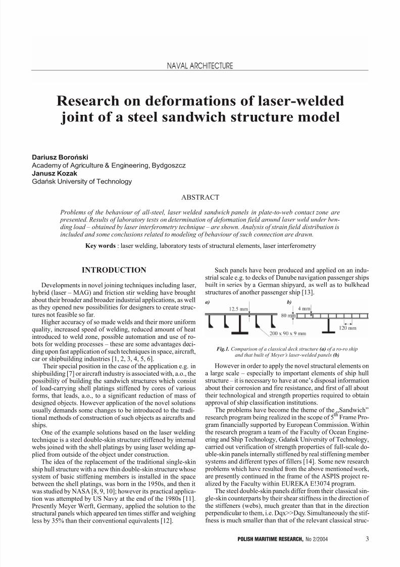
Such panels have been produced and applied on an indu-strial scale e.g. to decks of Danube navigation passenger ships built in series by a German shipyard, as well as to bulkheadstructures of another passenger ship [13].
However in order to apply the novel structural elements ona large scale especially to important elements of ship hullstructure it is necessary to have at ones disposal informationabout their corrosion and fire resistance, and first of all about
their technological and strength properties required to obtainapproval of ship classification institutions.The problems have become the theme of the Sandwich
research program being realized in the scope of 5th
Frame Pro-gram financially supported by European Commission. Withinthe research program a team of the Faculty of Ocean Engine-ering and Ship Technology, Gdañsk University of Technology,carried out verification of strength properties of full-scale do-uble-skin panels internally stiffened by real stiffening member systems and different types of fillers [14]. Some new research problems which have resulted from the above mentioned work,are presently continued in the frame of the ASPIS project re-alized by the Faculty within EUREKA E!3074 program.
The steel double-skin panels differ from their classical sin-
gle-skin counterparts by their shear stiffness in the direction of the stiffeners (webs), much greater than that in the direction perpendicular to them, i.e. Dqx>>Dqy. Simultaneously the stif-fness is much smaller than that of the relevant classical struc-
ABSTRACT
Problems of the behaviour of all-steel, laser welded sandwich panels in plate-to-web contact zone are presented. Results of laboratory tests on determination of deformation field around laser weld under ben-ding load obtained by laser interferometry technique are shown. Analysis of strain field distribution isincluded and some conclusions related to modeling of behaviour of such connection are drawn.
Key words : laser welding, laboratory tests of structural elements, laser interferometry
Fig.1. Comparison of a classical deck structure (a) of a ro-ro shipand that built of Meyers laser-welded panels (b)
a) b)
7/30/2019 PMRes_2004_2
http://slidepdf.com/reader/full/pmres20042 4/32
4 POLISH MARITIME RESEARCH, No 2/2004
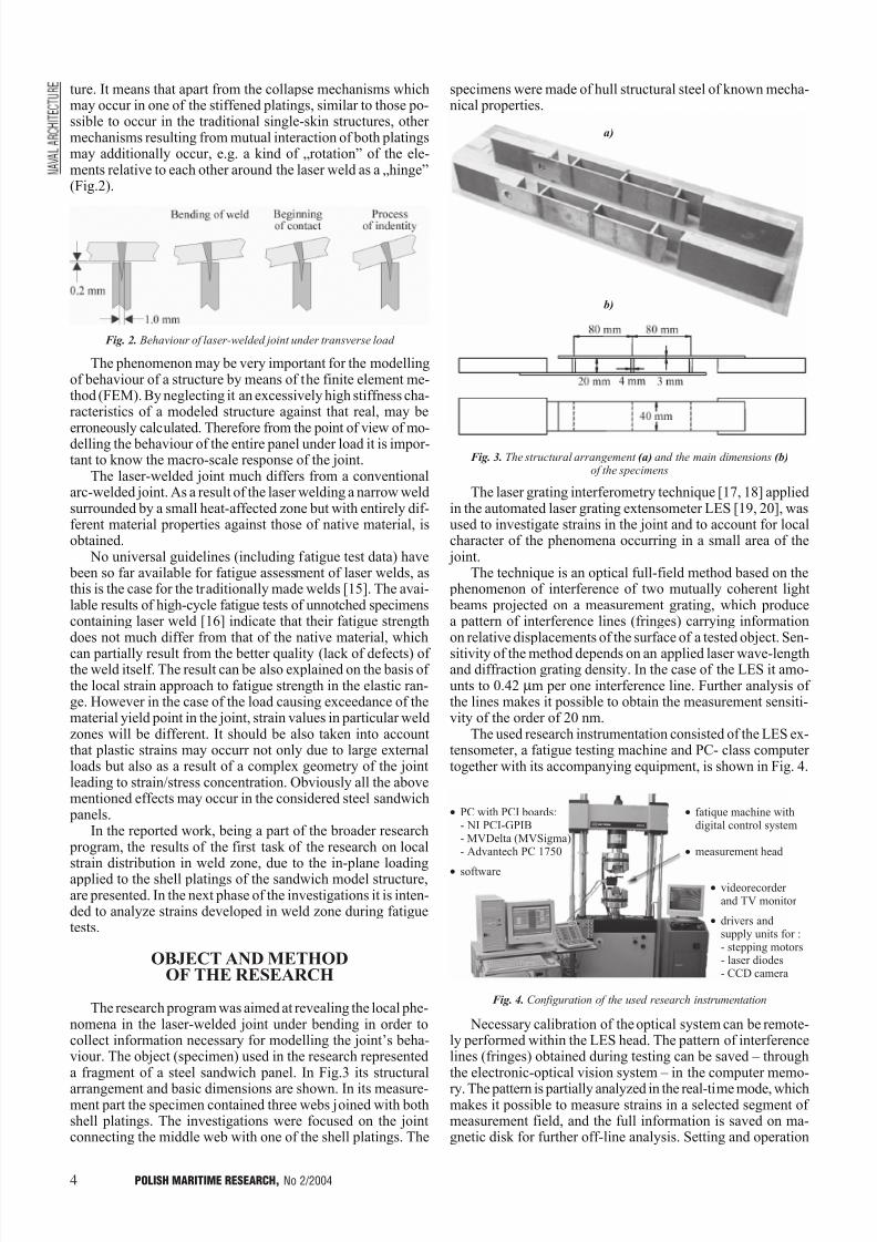
ture. It means that apart from the collapse mechanisms whichmay occur in one of the stiffened platings, similar to those po-ssible to occur in the traditional single-skin structures, other mechanisms resulting from mutual interaction of both platingsmay additionally occur, e.g. a kind of rotation of the ele-ments relative to each other around the laser weld as a hinge(Fig.2).
The phenomenon may be very important for the modellingof behaviour of a structure by means of the finite element me-thod (FEM). By neglecting it an excessively high stiffness cha-racteristics of a modeled structure against that real, may be
erroneously calculated. Therefore from the point of view of mo-delling the behaviour of the entire panel under load it is impor-tant to know the macro-scale response of the joint.
The laser-welded joint much differs from a conventionalarc-welded joint. As a result of the laser welding a narrow weldsurrounded by a small heat-affected zone but with entirely dif-ferent material properties against those of native material, isobtained.
No universal guidelines (including fatigue test data) have been so far available for fatigue assessment of laser welds, asthis is the case for the traditionally made welds [15]. The avai-lable results of high-cycle fatigue tests of unnotched specimenscontaining laser weld [16] indicate that their fatigue strengthdoes not much differ from that of the native material, which
can partially result from the better quality (lack of defects) of the weld itself. The result can be also explained on the basis of the local strain approach to fatigue strength in the elastic ran-ge. However in the case of the load causing exceedance of thematerial yield point in the joint, strain values in particular weldzones will be different. It should be also taken into accountthat plastic strains may occurr not only due to large externalloads but also as a result of a complex geometry of the jointleading to strain/stress concentration. Obviously all the abovementioned effects may occur in the considered steel sandwich panels.
In the reported work, being a part of the broader research program, the results of the first task of the research on local
strain distribution in weld zone, due to the in-plane loadingapplied to the shell platings of the sandwich model structure,are presented. In the next phase of the investigations it is inten-ded to analyze strains developed in weld zone during fatiguetests.
OBJECT AND METHOD
OF THE RESEARCH
The research program was aimed at revealing the local phe-nomena in the laser-welded joint under bending in order tocollect information necessary for modelling the joints beha-viour. The object (specimen) used in the research representeda fragment of a steel sandwich panel. In Fig.3 its structural
arrangement and basic dimensions are shown. In its measure-ment part the specimen contained three webs joined with bothshell platings. The investigations were focused on the jointconnecting the middle web with one of the shell platings. The
specimens were made of hull structural steel of known mecha-nical properties.
The laser grating interferometry technique [17, 18] appliedin the automated laser grating extensometer LES [19, 20], wasused to investigate strains in the joint and to account for localcharacter of the phenomena occurring in a small area of the joint.
The technique is an optical full-field method based on the phenomenon of interference of two mutually coherent light beams projected on a measurement grating, which producea pattern of interference lines (fringes) carrying informationon relative displacements of the surface of a tested object. Sen-
sitivity of the method depends on an applied laser wave-lengthand diffraction grating density. In the case of the LES it amo-unts to 0.42 mm per one interference line. Further analysis of the lines makes it possible to obtain the measurement sensiti-vity of the order of 20 nm.
The used research instrumentation consisted of the LES ex-tensometer, a fatigue testing machine and PC- class computer together with its accompanying equipment, is shown in Fig. 4.
Necessary calibration of the optical system can be remote-ly performed within the LES head. The pattern of interferencelines (fringes) obtained during testing can be saved throughthe electronic-optical vision system in the computer memo-
ry. The pattern is partially analyzed in the real-time mode, whichmakes it possible to measure strains in a selected segment of measurement field, and the full information is saved on ma-gnetic disk for further off-line analysis. Setting and operation
Fig. 2. Behaviour of laser-welded joint under transverse load
Fig. 3. The structural arrangement (a) and the main dimensions (b)of the specimens
Fig. 4. Configuration of the used research instrumentation
· PC with PCI boards:- NI PCI-GPIB- MVDelta (MVSigma)- Advantech PC 1750
· software
· fatique machine withdigital control system
· measurement head
· videorecorder and TV monitor
· drivers andsupply units for :- stepping motors- laser diodes- CCD camera
a)
b)
7/30/2019 PMRes_2004_2
http://slidepdf.com/reader/full/pmres20042 5/32
5POLISH MARITIME RESEARCH, No 2/2004
of the entire research instrumentation can be controlled bymeans of a special software.
The using of the laser interferometry method demands ap- plication of gratings placed onto the specimens surface. In theinvestigations in question the gratings of the density of 1200lines/mm obtained by dusting aluminium onto a matrix prepa-red on 2 x 2 glass plate, were used. During the preparation of the specimens for testing the 8 mm x 8 mm fragments of the
grating were put on the cleaned surface of the joint by glueingthe dusted aluminium layer, and then separating it from thematrix after setting the resin.
TEST RESULTS AND THEIR ANALYSIS
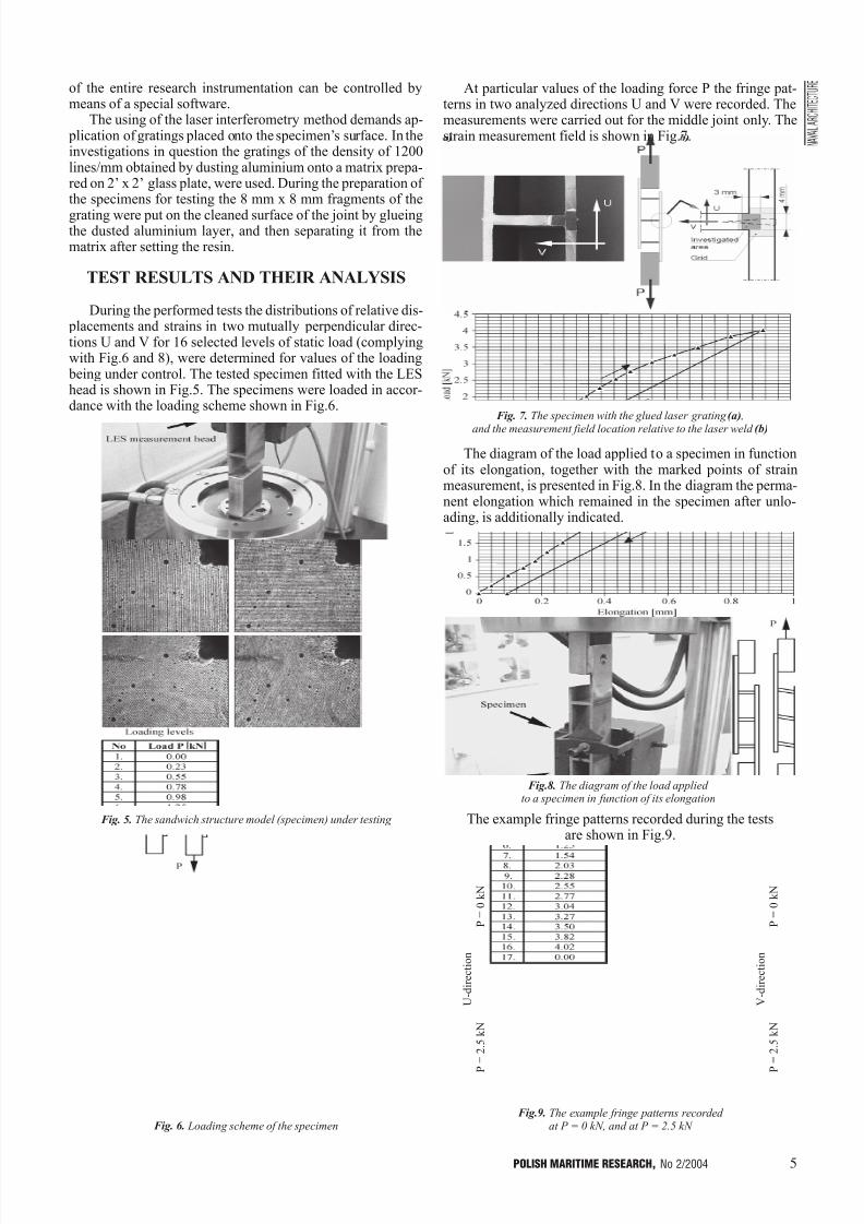
During the performed tests the distributions of relative dis- placements and strains in two mutually perpendicular direc-tions U and V for 16 selected levels of static load (complyingwith Fig.6 and 8), were determined for values of the loading being under control. The tested specimen fitted with the LEShead is shown in Fig.5. The specimens were loaded in accor-dance with the loading scheme shown in Fig.6.
At particular values of the loading force P the fringe pat-terns in two analyzed directions U and V were recorded. Themeasurements were carried out for the middle joint only. Thestrain measurement field is shown in Fig.7.
The diagram of the load applied to a specimen in functionof its elongation, together with the marked points of strainmeasurement, is presented in Fig.8. In the diagram the perma-nent elongation which remained in the specimen after unlo-ading, is additionally indicated.
The example fringe patterns recorded during the testsare shown in Fig.9.
Fig. 5. The sandwich structure model (specimen) under testing
Fig. 6. Loading scheme of the specimen
Fig. 7. The specimen with the glued laser grating (a) ,
and the measurement field location relative to the laser weld (b)
Fig.8. The diagram of the load applied to a specimen in function of its elongation
Fig.9. The example fringe patterns recorded at P = 0 kN, and at P = 2.5 kN
U - d i r e c t i o n
P
= 2 . 5
k N
P = 0 k N
V - d i r e c t i o n
P
= 2 . 5
k N
P = 0 k N

7/30/2019 PMRes_2004_2
http://slidepdf.com/reader/full/pmres20042 6/32
6 POLISH MARITIME RESEARCH, No 2/2004
The strain analysis was generally limited to the values of the force P = 2.5 kN as large strain values occurred in the con-tact zone of the web and shell plate, which exceeded the basicmeasuring range of the applied method (for the mode of auto-matic measuring and data recording), as well as due to the con-centration of fringes resulting from rotation of the specimenselements under loading.
The obtained fringe patterns were analyzed with the use of
numerical procedures making it possible to identify particular fringes and their phases within an analyzed field.
In Fig.10 and 11 are presented the strain distributions de-termined in the directions V and U, respectively, for successi-ve values of the external force P.
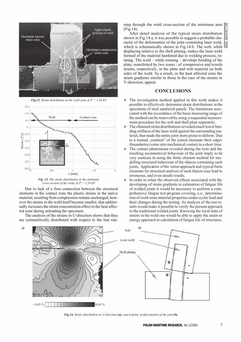
From the analysis of the obtained strain distributions alongV-axis it can be observed that the axial load applied to thespecimen in accordance with the loading scheme (Fig.8), ge-nerated a strain gradient typical for bending, in the surroun-dings of the weld joining the web with the shell plate.Simulta-
neously the edge of the web exerted contact pressure on theshell plate, that produced the compressive strain zones appe-aring both in the web and shell plate in the vicinity of thewebs edge. (Fig.12).
The largest values of tensile strains (along V- axis) in theanalyzed area occurred at the edge of the weld, and thoseof compressive strains in the web-to-plate contact zone(Fig.12).
Along with increasing the load the increasing strain valuesoccurred both in the compression and tension zones, alsoa gradual expansion of the zones into the plate material wasobserved.
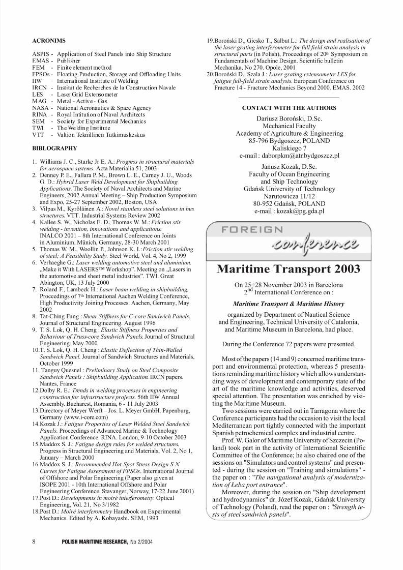
The combined influence of the web bending and the web--to-plate contact on the strain distribution in the minimum cross--section of the weld, is shown in Fig.13.
From the analysis of the presented strain distribution it re-sults that the neutral axis of bending, located close to the middle
of the weld, did not change its location despite the web came incontact with the plate during loading the specimen. As a result,only a deviation from linear distribution in the compressivestrain zone of the weld occurred. Simultaneuously the contact pressure of the web on the shell plate caused large plastic stra-
ins in the contact zone, which exceeded the strains in the welditself. Hence, such development of strains may indirectly indi-cate that the yield points of the weld, heat affected zone andnative material could significantly differ from each other.
Fig.11. Strain distributions in U-direction
Fig.10. Strain distributions in V-direction
7/30/2019 PMRes_2004_2
http://slidepdf.com/reader/full/pmres20042 7/32
7POLISH MARITIME RESEARCH, No 2/2004
Due to lack of a firm connection between the structuralelements in the contact zone the plastic strains in the nativematerial, resulting from compression remain unchanged, how-ever the strains in the weld itself become smaller, that additio-nally increases the strain concentration effect in the heat affec-ted zone during unloading the specimen.
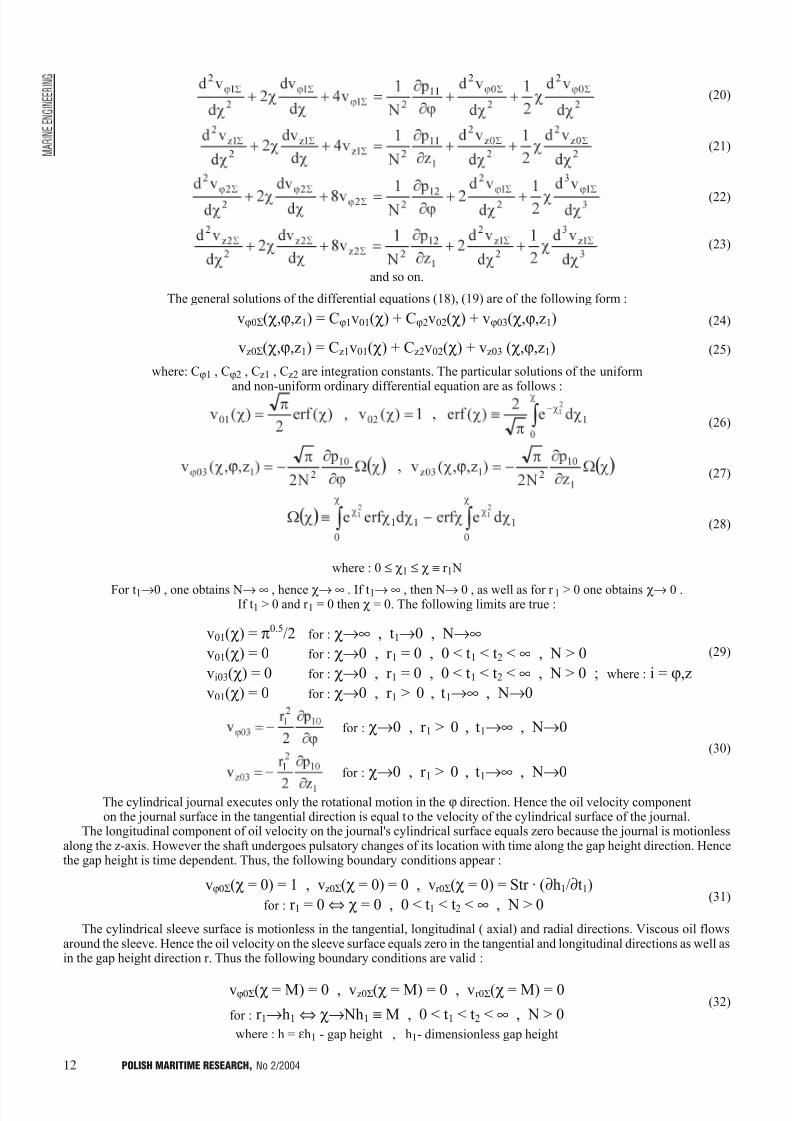
The analysis of the strains in U-direction shows that theyare symmetrically distributed with respect to the line run-
ning through the weld cross-section of the minimum area(Fig.14).
After detail analysis of the typical strain distributionshown in Fig.14.a, it was possible to suggest a probable cha-racter of the deformation of the joint containing laser weld,which is schematically shown in Fig.14.b. The web, whiledisplacing relative to the shell plating, makes the laser weldformed of the material hardened due to welding process, ro-
tating. The weld while rotating develops bending of the plate, manifested by two zones : of compressive and tensilestrains, respectively, in the plate and web material on bothsides of the weld. As a result, in the heat affected zone thestrain gradients similar to those in the case of the strains inV-direction, appear.
CONCLUSIONS
Ø The investigation method applied in this work makes it possible to effectively determine strain distributions in thespecimens of steel sandwich panels. The limitations asso-ciated with the exceedance of the basic measuring range of
the method can be removed by using a sequential measure-ment procedure for the web and shell plate separately.Ø The obtained strain distributions revealed much lower ben-
ding stiffness of the laser weld against the surrounding ma-terial, that made the entire joint more prone to deform. Dueto a mutual rotation of the joined elements their edges(boundaries) come into mechanical contact in a short time.
Ø The contact phenomena revealed during the tests and theresulting asymmetrical behaviour of the joint imply to bevery cautious in using the finite element method for mo-delling structural behaviour of the objects containing such joints. Application of the rutine approach and typical finiteelements for structural analysis of such objects may lead toerroneous, and even unsafe results.
Ø In order to relate the observed effects associated with thedeveloping of strain gradients to estimation of fatigue lifeof welded joints it would be necessary to perform a com- prehensive fatigue test program covering, a.o., determina-tion of weld-zone material properties under cyclic load andtheir changes during the testing. An analysis of the test re-sults would make it possible to verify the present approachto the traditional welded joints. Knowing the local state of strains in the weld one would be able to apply the strain or energy approach to calculation of fatigue life of structures.
Fig.12. Strain distribution in the weld zone at P = 1.54 kN
Fig. 13. The strain distribution in the minimumcross-section of the weld, at P = 1.54 kN
Fig.14. Strain distribution in U-direction (a) , and scheme of deformation of the joint (b)
a) b)
7/30/2019 PMRes_2004_2
http://slidepdf.com/reader/full/pmres20042 8/32
8 POLISH MARITIME RESEARCH, No 2/2004
ACRONIMS
ASPIS - Application of Steel Panels into Ship StructureEMAS - Publisher FEM - Finite element methodFPSOs - Floating Production, Storage and Offloading UnitsIIW - International Institute of WeldingIRCN - Institut de Recherches de la Construction NavaleLES - Laser Grid Extensometer
MAG - Metal - Active - Gas NASA - National Aeronautics & Space AgencyRINA - Royal Intitution of Naval ArchitectsSEM - Society for Experimental MechanicsTWI - The Welding InstituteVTT - Valtion Teknillinen Tutkimuskeskus
BIBLOGRAPHY
1. Williams J. C., Starke Jr E. A.: Progress in structural materials for aerospace systems. Acta Materialia 51, 2003
2. Denney P. E., Fallara P. M., Brown L. E., Carney J. U., WoodsG. D.: Hybrid Laser Weld Development for Shipbuilding Applications. The Society of Naval Architects and MarineEngineers, 2002 Annual Meeting Ship Production Symposiumand Expo, 25-27 September 2002, Boston, USA
3. Vilpas M., Kyröläinen A.: Novel stainless steel solutions in bus structures. VTT. Industrial Systems Review 2002
4. Kallee S. W., Nicholas E. D., Thomas W. M.: Friction stir welding - invention, innovations and applications.INALCO 2001 8th International Conference on Jointsin Aluminium. Mûnich, Germany, 28-30 March 2001
5. Thomas W. M., Woollin P., Johnson K. I.: Friction stir welding of steel; A Feasibility Study. Steel World, Vol. 4, No 2, 1999
6. Verhaeghe G.: Laser welding automotive steel and aluminium.Make it With LASERS Workshop. Meeting on Lasers inthe automotive and sheet metal industries. TWI. GreatAbington, UK, 13 July 2000
7. Roland F., Lambeck H.: Laser beam welding in shipbuilding .Proceedings of 7th International Aachen Welding Conference,High Productivity Joining Processes. Aachen, Germany, May2002
8. Tat-Ching Fung : Shear Stiffness for C-core Sandwich Panels.Journal of Structural Engineering. August 1996
9. T. S. Lok, Q. H. Cheng : Elastic Stiffness Properties and Behaviour of Truss-core Sandwich Panels. Journal of StructuralEngineering. May 2000
10.T. S. Lok, Q. H. Cheng : Elastic Deflection of Thin-Walled Sandwich Panel . Journal of Sandwich Structures and Materials,October 1999
11. Tanguy Quesnel : Preliminary Study on Steel CompositeSandwich Panels : Shipbuilding Application. IRCN papers. Nantes, France
12.Dolby R. E.: Trends in welding processes in engineering
construction for infrastructure projects. 56th IIW AnnualAssembly. Bucharest, Romania, 6 - 11 July 200313.Directory of Meyer Werft Jos. L. Meyer GmbH. Papenburg,
Germany (www.i-core.com)14.Kozak J.: Fatigue Properties of Laser Welded Steel Sandwich
Panels. Proceedings of Advanced Marine & TechnologyApplication Conference. RINA. London, 9-10 October 2003
15.Maddox S. J.: Fatigue design rules for welded structures.Progress in Structural Engineering and Materials, Vol. 2, No 1,January March 2000
16.Maddox S. J.: Recommended Hot-Spot Stress Design S-N Curves for Fatigue Assessment of FPSOs. International Journalof Offshore and Polar Engineering (Paper also given atISOPE 2001 - 10th International Offshore and Polar Engineering Conference. Stavanger, Norway, 17-22 June 2001)
17.Post D.: Developments in moiré interferometry. OpticalEngineering, Vol. 21, No 3/1982
18.Post D.: Moiré interferometry Handbook on ExperimentalMechanics. Edited by A. Kobayashi. SEM, 1993
19.Boroñski D., Giesko T., Sa³but L.: The design and realisation of the laser grating interferometer for full field strain analysis in structural parts (in Polish), Proceedings of 20th Symposium onFundamentals of Machine Design. Scientific bulletinMechanika, No 270. Opole, 2001
20.Boroñski D., Szala J.: Laser grating extensometer LES for fatigue full-field strain analysis. European Conference onFracture 14 - Fracture Mechanics Beyond 2000. EMAS. 2002
CONTACT WITH THE AUTHORS
Dariusz Boroñski, D.Sc.Mechanical Faculty
Academy of Agriculture & Engineering85-796 Bydgoszcz, POLAND
Kaliskiego 7e-mail : [email protected]
Janusz Kozak, D.Sc.Faculty of Ocean Engineering
and Ship TechnologyGdañsk University of Technology
Narutowicza 11/1280-952 Gdañsk, POLANDe-mail : [email protected]
Maritime Transport 2003
On 25÷28 November 2003 in Barcelona2
ndInternational Conference on :
Maritime Transport & Maritime History
organized by Department of Nautical Scienceand Engineering, Technical University of Catalonia,
and Maritime Museum in Barcelona, had place.
During the Conference 72 papers were presented.
Most of the papers (14 and 9) concerned maritime trans- port and environmental protection, whereas 5 presenta-tions reminding maritime history which allows understan-ding ways of development and contemporary state of theart of the maritime knowledge and activities, deservedspecial attention. The presentation was enriched by visi-ting the Maritime Museum.
Two sessions were carried out in Tarragona where theConference participants had the occasion to visit the localMediterranean port tightly connected with the importantSpanish petrochemical complex and industrial centre.
Prof. W. Galor of Maritime University of Szczecin (Po-land) took part in the activity of International ScientificCommittee of the Conference; he also chaired one of thesessions on "Simulators and control systems" and presen-ted - during the session on "Training and simulations" -the paper on : "The navigational analysis of moderniza-tion of £eba port entrance".
Moreover, during the session on "Ship development
and hydrodynamics" dr. Józef Kozak, Gdañsk Universityof Technology (Poland), read the paper on : "Strength te- sts of steel sandwich panels".

7/30/2019 PMRes_2004_2
http://slidepdf.com/reader/full/pmres20042 9/32
9POLISH MARITIME RESEARCH, No 2/2004
INTRODUCTION
Correctness assessment of functioning the machines used for driving systems of various transport means e.g. diesel enginesin which journal friction units are installed, depends to a large extent on assumed computational models, correct estimation of assumed appropriate simplifications, if necessary, and then on an assumed numerical method for the determining of operational
parameters. During maneouvres of sea-going ships as well as when driving cars many frequent changes of engine operational parameters occur, especially of its rotational speed and loading. Similarly it happens during sailing the ship in rough weather when non-stationary loads on its propulsion engine happen.
Both car vehicles and majority of sea-going ships are equipped with a propulsion system of a single self-ignition combustionengine. Seizure of trigological system of such engine is equivalent to depriving the vehicle or ship of its propulsion and therebyof its serviceability [3]. If such an event occurs during storm emergency situations or even a catastrophy may happen [4]. One of the ways to avoid such failures is to apply a lubricating oil of required properties, especially of appropriate viscosity and lubricity.
Therefore the main aim of this work is to present analytical-numerical calculations of distributions of hydrodynamic pressurevalues occurring during non-stationary impulse lubrication of bearing surfaces at viscoelastic oil flow. Viscoelastic properties arecharacteristic for all oils which contain various bettering admixtures or in which some impurities such as lead salts, soot or dust,happen. All such impurities and admixtures are typical for land and sea transport.
Taking into account the above mentioned observations it is necessary to precisely analyze the influence of non-stationaryload impulses which are transferred through a propulsion system to a slide friction unit and result in such characteristic quantityof the bearing as its load-carrying capacity determined on the basis of pressure distributions.
In Fig.1 the structure and loading scheme of a slide journal bearing is presented.
Viscoelastic unsteady lubrication of radial slide journal bearing at impulsive motion
Andrzej Miszczak
Gdynia Maritime University
ABSTRACT
This paper presents an analytical solution of velocity components of unsymmetrical oil flow and pressure distribution in radial journal bearing gap for hydrodynamic unsteadylubrication with viscoelastic oil. Numerical calculations are performed in Mathcad 11
Professional Program, with taking into account the method of finite differences. This me-thod satisfies stability conditions of numerical solutions of partial differential equationsand values of capacity forces occurring in cylindrical bearings. Exact calculations of pres-
sure in journal bearing and its load capacity may be useful to prevent from prematurewear tribological units of self ignition engines, especially those applied in ships.
Key words : viscoelastic unsteady lubrication, analytical and numerical calculation, capacity forces, hydrodynamic pressure
Fig. 1. Structure and loading scheme of a radial slide journal bearing and its characteristic dimensions

7/30/2019 PMRes_2004_2
http://slidepdf.com/reader/full/pmres20042 10/32
10 POLISH MARITIME RESEARCH, No 2/2004
As shown in the scheme the bearing sleeve axis may undergo a skew respective to the journal axis. The quantity is described by the angle g . In such case the oil gap height depends on the tangential variable j and the longitudinal coordinate z. In the caseof non-stationary impulse loads the oil gap height additionally depends on time t.
THEORETICAL MODEL
Oil flow through the cylindrical gap height of radial slide bearing is described by the momentum conservation equations andcontinuity equation [1, 2, 6, 7, 8, 10, 11, 15]. Additionally, Rivlin-Ericksen constitutive relationships were assumed. The equ-
ations in question are of the following form :Div S = rdv/dt , div v = 0 , S = -pI + hoA1 + a(A1)
2+ bA2
where :
The coordinates of A1, A2 tensors are described by the symmetrical matrices defined as follows :
A1 º
L+
LT
A2 º grad a + (grad a)T
+ 2LTL (2)
a º Lv +t∂
∂v
where :
The product of the Deborah and Strouhal numbers, marked DeStr, is assumedof the same order as the productof the Reynold's number, relative radial clearance and Strouhal number, marked ReyStr. Moreover : DeStr >> De º aw/ho .
where : y - relative radial clearence, and w - angular speed of cylindrical bearing journal.
Neglecting the terms for the relative radial clearance y º e/R @ 10-3
in the basic equations defined in the cylindrical coordi-nate frame : j, r, z, as well as taking into account the above mentioned assumptions, one can obtain :
(3)
(4)
(5)
(6)
for : 0 £ j < 2p , -b £ z £ +b , 0 £ r £ h , where : h - characteristic gap height.
The symbols: vj, v
r , v
zrepresent the respective oil velocity vector components : tangentially directed, that along gap height, and
longitudinally directed. The following relationships between the dimensional and dimensionless quantities are assumed [12 , 13] :
r = R(1+yr 1) , z = bz1 , t = tot1 , h = eh1 , vj = Uvj1 , vr º Uy vr1
vz º (U/L1) vz1 , p = po p1 , po º UhoR/e2
, L1 = b/R (7)
The following is additionally assumed :
Ø rotational motion of the journal with the tangential speed U = wR Ø unsymmetrical, non-stationary oil flow through bearing gap heightØ non-stationary viscoelastic properties of oilØ constant oil density rØ the characteristic gap height h(j,z,t), in the cylindrical bearingØ no slip between bearing surfacesØ R - radius of cylindrical journalØ 2b - length of the bearing in question.
L - tensor of oil velocity vector gradient s-1
a - acceleration vector L
T - tensor with matrix transpose s-1
grad a - acceleration vector gradient
S - stress tensor r - oil densityDiv S - stress tensor divergence t - timev - velocity vector p - pressurediv v - velocity vector divergence I - unit tensor
(1)
A1 and A2 - two Rivlin-Ericksen strain tensors of three material constants ho, a, b,where :
ho - dynamic viscosity a, b - pseudo-viscosity constans of oil

7/30/2019 PMRes_2004_2
http://slidepdf.com/reader/full/pmres20042 11/32
11POLISH MARITIME RESEARCH, No 2/2004
Reynolds number, modified Reynolds number, Strouhal and Deborah number are assumed in the following forms :
(8)
hence : DeStr = b/(hoto) º Des , ReyStr = re2/(hoto) º Res (8a)
For the commonly applied inhibitors the coefficient b satisfies the inequality: 0 < b/to < ho. Values of the coefficient b varyfrom 0.000001 Pa·s
2to 0.01 Pa·s
2. The dimensionless symbols are marked with the lower index "1". The equations (3) ÷ (6) take
the dimensionless form :
(9)
(10)
(11)
(12)
for : 0 £ j < 2p , -1 £ z1 £ +1 , 0 £ r 1 £ h1
GENERAL AND PARTICULAR SOLUTIONS
A new variable is now introduced :
(13)
and solutions are assumed to have the form of the following convergent series [5] :
(14)
(15)
(16)
(17)
for : t1 > 0 , 0 < Des << 1 , (Des/t1) < 1
In the equations (9) ÷ (11) the derivatives respective to the variables t1, r 1 are substituted for the derivatives relative to thevariable c, by using the relationships given in App. 1. Therefore the variables t1, r 1 are substituted for the variable c. Now theseries (14) ÷ (17) are introduced to the equation system (9) ÷ (11). Next, the terms multiplied by the parameters of the same power, (Des/t1)
k , are successively compared for k = 0, 1, 2, ... . Hence the following sequence of ordinary differential equations
is obtained:
(18)
(19)
Re º rUe/ho , Rey º rwe2/ho , Str º R/(Uto) , De º bU/(hoR)
7/30/2019 PMRes_2004_2
http://slidepdf.com/reader/full/pmres20042 12/32
12 POLISH MARITIME RESEARCH, No 2/2004
(20)
(21)
(22)
(23)
and so on.
The general solutions of the differential equations (18), (19) are of the following form :
(24)
(25)
where: Cj1 , Cj2 , Cz1 , Cz2 are integration constants. The particular solutions of the uniform
and non-uniform ordinary differential equation are as follows :
(26)
(27)
(28)
where : 0 £ c1 £ c º r 1 N
For t1®0 , one obtains N® ¥ , hence c® ¥ . If t1® ¥ , then N® 0 , as well as for r 1 > 0 one obtains c® 0 .If t1 > 0 and r 1 = 0 then c = 0. The following limits are true :
(29)
(30)
The cylindrical journal executes only the rotational motion in the j direction. Hence the oil velocity componenton the journal surface in the tangential direction is equal to the velocity of the cylindrical surface of the journal.
The longitudinal component of oil velocity on the journal's cylindrical surface equals zero because the journal is motionlessalong the z-axis. However the shaft undergoes pulsatory changes of its location with time along the gap height direction. Hencethe gap height is time dependent. Thus, the following boundary conditions appear :
vj0S(c = 0) = 1 , vz0S(c = 0) = 0 , vr0S(c = 0) = Str · (¶h1/¶t1)
for : r 1 = 0 Û c = 0 , 0 < t1 < t2 < ¥ , N > 0(31)
The cylindrical sleeve surface is motionless in the tangential, longitudinal ( axial) and radial directions. Viscous oil flowsaround the sleeve. Hence the oil velocity on the sleeve surface equals zero in the tangential and longitudinal directions as well asin the gap height direction r. Thus the following boundary conditions are valid :
vj0S(c = M) = 0 , vz0S(c = M) = 0 , vr0S(c = M) = 0(32)
where : h = eh1 - gap height , h1- dimensionless gap height
v01(c) = p0.5/2 for : c®¥ , t1®0 , N®¥
v01(c) = 0 for : c®0 , r 1 = 0 , 0 < t1 < t2 < ¥ , N > 0
vi03(c) = 0 for : c®0 , r 1 = 0 , 0 < t1 < t2 < ¥ , N > 0 ; where : i = j,z
v01(c) = 0 for : c®0 , r 1 > 0 , t1®¥ , N®0
vj0S(c,j,z1) = Cj1v01(c) + Cj2v02(c) + vj03(c,j,z1)
vz0S(c,j,z1) = Cz1v01(c) + Cz2v02(c) + vz03 (c,j,z1)
for : c®0 , r 1 > 0 , t1®¥ , N®0
for : c®0 , r 1 > 0 , t1®¥ , N®0
for : r 1®h1 Û c® Nh1 º M , 0 < t1 < t2 < ¥ , N > 0

7/30/2019 PMRes_2004_2
http://slidepdf.com/reader/full/pmres20042 13/32
13POLISH MARITIME RESEARCH, No 2/2004
Applying the conditions (31), (32) to the solutions (24), (25) one obtains :
If the limits (29), (30) are taken into account the set of equations (33) yields the following solutions :
(34)
Now, to the right hand sides of the equations (20), (21) the solutions (24), (25), (26), (27), (28), (34) are substituted.Hence the general solution of the equations (20), (21) obtains the following form :
(35)
(36)
where : Cj3 , Cj4 , Cz3 , Cz4 - integration constants
The particular solutions are as follows :
(37)
(38)
(39)
for : 0 < d £ c1 £ c
The solutions (35), (36) represent corrections to the components of oil velocity because of its viscoelastic properties.On the basis of the solutions (37) ÷ (39) for c® 0 , r
1® 0 , N > 0 the following limits are achieved :
(40)
The following limits are also true :
The corrections to the oil velocity components cannot have the same boundary conditions as those previously assumed (31),(32) for the cylindrical journal and sleeve in the longitudinal and tangential directions. Therefore the corrections satisfy thefollowing boundary conditions :
Cj1v01(c = 0) + Cj2 + vj03(c = 0) = 1 for : r 1 = 0
Cj1v01(c = M) + Cj2 + vj03(c = M) = 0 for : r 1 = h1
Cz1v01(c = 0) + Cz2 + vz03(c = 0) = 0 for : r 1 = 0
Cz1v01(c = M) + Cz2 + vz03(c = M) = 0 for : r 1 = h1
(33)
(41)v11(c) = 0 for : c®0 , r 1 = 0 , 0 < t1 < t2 < ¥ , N > 0v12(c) = -1 for : c®0 , r 1 = 0 , 0 < t1 < t2 < ¥ , N > 0
vi13(c) = 0 for : c®0 , r 1 = 0 , 0 < t1 < t2 < ¥ , N > 0 ; where i = j, z
(42)vj1S(c = 0) = 0 , vz1S(c = 0) = 0 for : r 1 = 0 Û c = 0 , 0 < t1 < t2 < ¥ , N > 0
vj1S(c = M) = 0 , vz1S(c = M) = 0 for : r 1®h1 Û c® Nh1 º M , 0 < t1 < t2 < ¥ , N > 0
7/30/2019 PMRes_2004_2
http://slidepdf.com/reader/full/pmres20042 14/32
14 POLISH MARITIME RESEARCH, No 2/2004
Applying the conditions (42) to the general solutions (35), (36) one obtains :
Cj3v11(c = 0) + Cj4v12(c = 0) + vj13(c = 0) = 0 for : r 1 = 0
Cj3v11(c = M) + Cj4v12(c = M) + vj13(c = M) = 0 for : r 1 = h1
Cz3v11(c = 0) + Cz4v12(c = 0) + vz13(c = 0) = 0 for : r 1 = 0
Cz3v11(c = M) + Cz4v12(c = M) + vz13(c = M) = 0 for : r 1 = h1
If the limits (41) are accounted for the set of equations (43) yields the following solutions :
(44)
The general solutions of the oil velocity components (15), (14) at making use of the solutions (25), (35), (36),can be presented in the following form :
(45)
(46)
If t1®¥ then N®0 , hence c º r 1 N®0.For further analysis it is worthwhile to find the following limits :
(47)
(48)
for : 0 £ c1 £ h1 N , 0 < t1 < ¥ , 0 £ r 1 £ h1 , -1 £ z1 £ +1 , 0 < j < 2p
VALUES OF OIL VELOCITY AND PRESSURE
AT NON-STATIONARY NEWTONIAN LUBRICATION
If viscoelastic properties of oil are neglected, then on the basis of the solutions (45), (46)the oil velocity components in the j and z directions, at non-stationary flow, are of the following form :
(49)
(50)
for : 0 £ t1 < ¥ , 0 £ r 1 £ h1 , -1 £ z1 £ 1 , 0 < j < 2p , 0 £ c2 £ c1 £ c º r 1 N £ h1 N º M , h1 = h1(j,z1)
The oil velocity components (49), (50) are now inserted to the continuity equation (12)and next the equation is integrated respective to the variable r 1.
The oil velocity component vr0S in the gap height direction is not equal to zero on the cylindrical journal surface due toimpulse displacements of the shaft. Therefore by applying the condition vr0S = Str ¶h1/¶t1 for r 1 = 0, the following form of this oilvelocity component is obtained :
(51)
for : 0 £ t1 < ¥ , 0 £ r 2 £ r 1 £ h1 , -1 £ z1 £ +1 , 0 < j < 2p , 0 £ c2 £ c1 £ c º r 1 N £ h1 N º M
The oil velocity component vr0S equals zero on the sleeve surface. Integrating the continuity equation (12) along the direc-tion r and applying the boundary condition (32) for r 1 = h1 to the oil velocity component in the gap height direction, and making
use of the conditions (29) one obtains the equation :
(52)
(43)

7/30/2019 PMRes_2004_2
http://slidepdf.com/reader/full/pmres20042 15/32
15POLISH MARITIME RESEARCH, No 2/2004
The solutions (49) ÷ (50) are now inserted to the equation (52). One then obtains the following modified Reynolds equation :
(53)
for : 0 £ r 2 £ r 1 £ h1 , 0 £ j < 2p , -1 £ z1 < +1 , 0 £ t1 < ¥ , 0 £ c1 £ c £ h1 N , 0 £ N(t1) = 0.5(Res/t1)0.5
< ¥
The modified Reynolds equation (53) defines an unknown pressure function p10 (j, z1, t1). If the dimensionless time t1approaches infinity, i.e. the coefficient N approaches zero, then the equation (53) approaches the classical Reynolds equation(see App. 2) :
(54)
for : 0 £ j < 2p , -1 £ z1 < +1
The dimensionless time-dependent height of the bearing gap height, at accounting for its periodical disturbances,may be described by the following relationship :
h1 = [1 + l · cosj + s · z · cos(j)] · f(t1) ; f(t1) = [1 + c · exp(-to · t1 · wo)] (55)
where : ( ) γ ψ
= tanL
s - skew coefficient.
The symbol wo stands for an angular velocity given in [s-1
] which describes the disturbances in the gap height direction for unsteady oil flow through the cylindrical bearing gap height, and "c" stands for a coefficient used to control values of gap heightchanges. If c- value is positive the bearing gap height is increased, if negative - the bearing gap height is decreased relative to theclassical gap height. If t1 approaches infinity then the gap height equation (55) approaches the classical gap height equationindependent on time during stationary motion.
PRESSURE CORRECTIONS FOR VISCOELASTIC OIL PROPERTIES
Particular solutions of oil velocity components in the directions j and z1 due to viscoelastic properties in non-stationarymotion are contained in the solutions (14) , (16) multiplied by the term DeStr/t1. By making use of (38), (39), (44) and the boundary conditions (42), the corrections of the oil velocity components (35) , (36) can be transformed to the following forms :
(56)
7/30/2019 PMRes_2004_2
http://slidepdf.com/reader/full/pmres20042 16/32
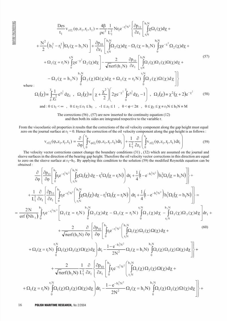
16 POLISH MARITIME RESEARCH, No 2/2004
(57)
where :
(58)
and : 0 £ t1 < ¥ , 0 £ r 2 £ r 1 £ h1 , -1 £ z1 £ 1 , 0 < j < 2p , 0 £ c1 £ c º r 1 N £ h1 N º M
The corrections (56) , (57) are now inserted to the continuity equation (12)and then both its sides are integrated respective to the variable r.
From the viscoelastic oil properties it results that the corrections of the oil velocity component along the gap height must equalzero on the journal surface at r 1 = 0. Hence the correction of the oil velocity component along the gap height is as follows :
(59)
The velocity vector corrections cannot change the boundary conditions (31) , (32) which are assumed on the journal andsleeve surfaces in the direction of the bearing gap height. Therefore the oil velocity vector corrections in this direction are equalto zero on the sleeve surface at r 1=h1. By applying this condition to the solution (59) the modified Reynolds equation can beobtained :
(60)
7/30/2019 PMRes_2004_2
http://slidepdf.com/reader/full/pmres20042 17/32
17POLISH MARITIME RESEARCH, No 2/2004
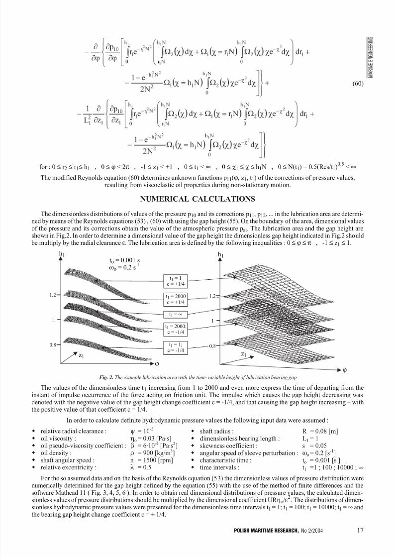
Fig. 2. The example lubrication area with the time-variable height of lubrication bearing gap
(60)
for : 0 £ r 2 £ r 1£ h1 , 0 £ j < 2p , -1 £ z1 < +1 , 0 £ t1 < ¥ , 0 £ c1 £ c £ h1 N , 0 £ N(t1) = 0.5(Res/t1)0.5
< ¥
The modified Reynolds equation (60) determines unknown functions p11(j, z1, t1) of the corrections of pressure values,resulting from viscoelastic oil properties during non-stationary motion.
NUMERICAL CALCULATIONS
The dimensionless distributions of values of the pressure p10 and its corrections p11, p12, ... in the lubrication area are determi-ned by means of the Reynolds equations (53) , (60) with using the gap height (55). On the boundary of the area, dimensional valuesof the pressure and its corrections obtain the value of the atmospheric pressure pat. The lubrication area and the gap height areshown in Fig.2. In order to determine a dimensional value of the gap height the dimensionless gap height indicated in Fig.2 should
be multiply by the radial clearance e. The lubrication area is defined by the following inequalities : 0 £ j £ p , -1 £ z1 £ 1.
The values of the dimensionless time t1 increasing from 1 to 2000 and even more express the time of departing from theinstant of impulse occurrence of the force acting on friction unit. The impulse which causes the gap height decreasing wasdenoted with the negative value of the gap height change coefficient c = -1/4, and that causing the gap height increasing withthe positive value of that coefficient c = 1/4.
In order to calculate definite hydrodynamic pressure values the following input data were assumed :
w relative radial clearance : y = 10-3
w oil viscosity : ho = 0.03 [Pa·s]w oil pseudo-viscosity coefficient : b = 6·10-4 [Pa·s2]w oil density : r = 900 [kg/m3]w shaft angular speed : n = 1500 [rpm]w relative excentricity : l = 0.5
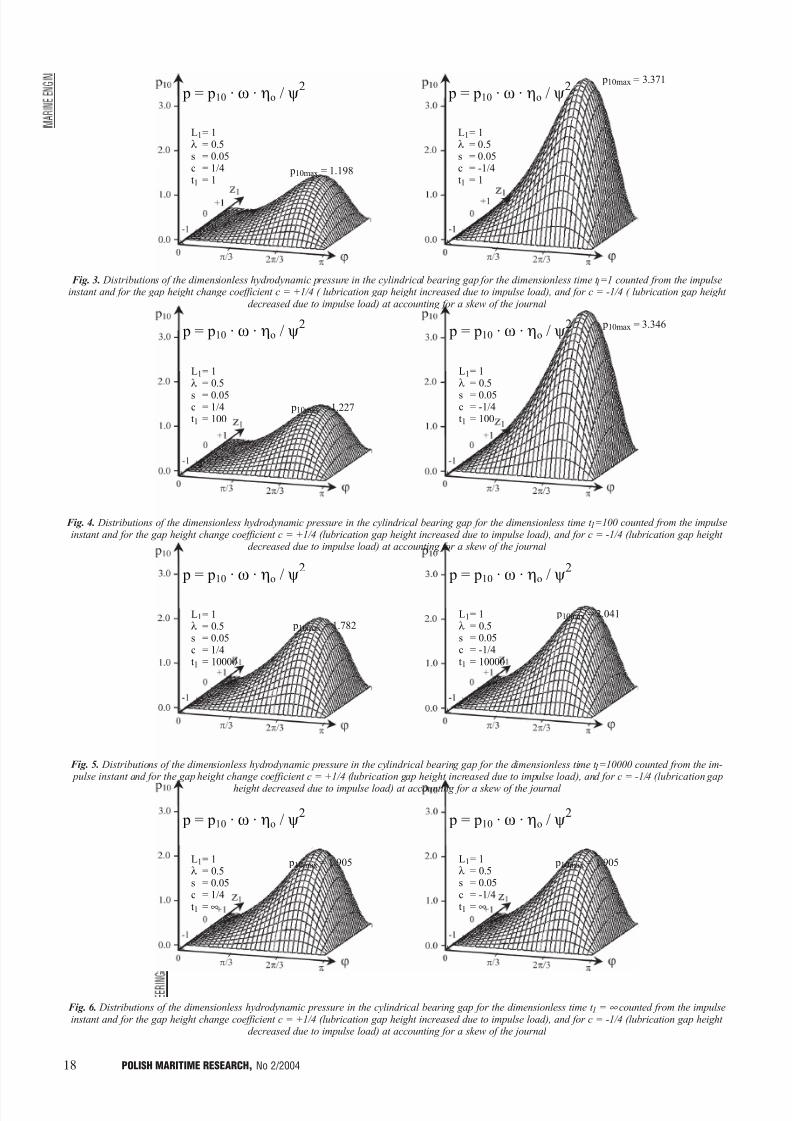
For the so assumed data and on the basis of the Reynolds equation (53) the dimensionless values of pressure distribution werenumerically determined for the gap height defined by the equation (55) with the use of the method of finite differences and thesoftware Mathcad 11 ( Fig. 3, 4, 5, 6 ). In order to obtain real dimensional distributions of pressure values, the calculated dimen-sionless values of pressure distributions should be multiplied by the dimensional coefficient UR ho/e
2. The distributions of dimen-
sionless hydrodynamic pressure values were presented for the dimensionless time intervals t1 = 1; t1 = 100; t1 = 10000; t1 = ¥ andthe bearing gap height change coefficient c = ± 1/4.
w shaft radius : R = 0.08 [m]w dimensionless bearing length : L1 = 1w skewness coefficient : s = 0.05w angular speed of sleeve perturbation : wo = 0.2 [s-1]w characteristic time : to = 0.001 [s ]w time intervals : t1 =1 ; 100 ; 10000 ; ¥
1.2
1
0.8
1.2
1
0.8
to = 0.001 swo = 0.2 s
-1
h1
j
h1
j
z1z1
t1 = 1c = +1/4
t1 = 2000c = +1/4
t1 = ¥
t1 = 2000;c = -1/4
t1 = 1;c = -1/4
7/30/2019 PMRes_2004_2
http://slidepdf.com/reader/full/pmres20042 18/32
18 POLISH MARITIME RESEARCH, No 2/2004
Fig. 5. Distributions of the dimensionless hydrodynamic pressure in the cylindrical bearing gap for the dimensionless time t 1=10000 counted from the im- pulse instant and for the gap height change coefficient c = +1/4 (lubrication gap height increased due to impulse load), and for c = -1/4 (lubrication gap
height decreased due to impulse load) at accounting for a skew of the journal
Fig. 3. Distributions of the dimensionless hydrodynamic pressure in the cylindrical bearing gap for the dimensionless time t 1=1 counted from the impulseinstant and for the gap height change coefficient c = +1/4 ( lubrication gap height increased due to impulse load), and for c = -1/4 ( lubrication gap height
decreased due to impulse load) at accounting for a skew of the journal
Fig. 4. Distributions of the dimensionless hydrodynamic pressure in the cylindrical bearing gap for the dimensionless time t 1=100 counted from the impulseinstant and for the gap height change coefficient c = +1/4 (lubrication gap height increased due to impulse load), and for c = -1/4 (lubrication gap height
decreased due to impulse load) at accounting for a skew of the journal
Fig. 6. Distributions of the dimensionless hydrodynamic pressure in the cylindrical bearing gap for the dimensionless time t 1 = ¥ counted from the impulseinstant and for the gap height change coefficient c = +1/4 (lubrication gap height increased due to impulse load), and for c = -1/4 (lubrication gap height
decreased due to impulse load) at accounting for a skew of the journal
p = p10 · w · ho / y2
L1= 1l = 0.5s = 0.05c = 1/4t1 = 1
p10max = 1.198
p = p10 · w · ho / y2
L1= 1l = 0.5s = 0.05c = -1/4t1 = 1
p10max = 3.371
p = p10 · w · ho / y2
L1= 1l = 0.5
s = 0.05c = -1/4t1 = 100
p10max = 3.346 p = p10 · w · ho / y
2
L1= 1l = 0.5
s = 0.05c = 1/4t1 = 100
p10max = 1.227
p = p10 · w · ho / y2
L1= 1l = 0.5s = 0.05c = -1/4t1 = 10000
p10max = 2.041
p = p10 · w · ho / y2
L1= 1l = 0.5s = 0.05c = 1/4t1 = 10000
p10max = 1.782
p = p10 · w · ho / y2
L1= 1l = 0.5s = 0.05c = -1/4t1 = ¥
p10max = 1.905
p = p10 · w · ho / y2
L1= 1l = 0.5s = 0.05c = 1/4t1 = ¥
p10max = 1.905

7/30/2019 PMRes_2004_2
http://slidepdf.com/reader/full/pmres20042 19/32
19POLISH MARITIME RESEARCH, No 2/2004
Fig.7. Distributions of the dimensionless values of the hydrodynamic pressure corrections resulting from viscoelastic properties of oil in the cylindrical bear-
ing gap for the dimensionless time t 1 = 1 counted from the impulse occurrence instant and for the gap height change coefficient c = +1/4 (lubrication gapheight increased due to impulse load), and for c = -1/4 (lubrication gap height decreased due to impulse load) at accounting for a skew of the journal
Fig.8. Distributions of the dimensionless values of the hydrodynamic pressure corrections resulting from viscoelastic properties of oil in the cylindrical bear-ing gap for the dimensionless time t 1 = 2 counted from the impulse occurrence instant and for the gap height change coefficient c = +1/4 (lubrication gap
height increased due to impulse load), and for c = -1/4 (lubrication gap height decreased due to impulse load) at accounting for a skew of the journal
Fig.9. Distributions of the dimensionless values of the hydrodynamic pressure corrections resulting from viscoelastic properties of oil in the cylindrical bear-ing gap for the dimensionless time t 1 = 10 counted from the impulse occurrence instant and for the gap height change coefficient c = +1/4 (lubrication gap
height increased due to impulse load), and for c = -1/4 (lubrication gap height decreased due to impulse load) at accounting for a skew of the journal
For the same data on the basis of the equation (60) the numerical calculations of the dimensionless values of hydrodynamic pressure corrections which result from oil viscoelastic properties, were performed. Their results are presented in Fig. 7, 8, 9 for the dimensionless time intervals t1 = 1, 2, 10. For t1 = 100, t1 = 10000 and t1 = ¥, the calculations of dimensionless values of thehydrodynamic pressure corrections were also performed, but they have not been attached here as being negligible. To obtaindimensional values of the pressure corrections the dimensionless values shown in Fig. 7, 8, 9, should be multiplied by thedimensional coefficient UR ho/e
2.
In Fig. 6 one can observe that when a load impulse occurs sufficiently far in time from the impulse occurrence instant, i.e.when t1® ¥, then the distributions of pressure values approach the pressure distribution identical as regards its values and shape, both at the impulse increasing the gap height c > 0 and that decreasing the gap height c < 0, which can be also achieved from theclassical Reynolds equation (54).
From the analysis of the pressure corrections (due to viscoelastic oil properties) it results that only in the initial instant t1 = 1
after impulse occurrence (Fig.7) the corrections really influence the total pressure value. At the so assumed time instant t1 = 1 theshare of the corrections of pressure p11 in the value of the basic pressure p10 amounts to about 6% (at the gap height decreaseddue to impulse load, c = -1/4) and to about 18% (at that gap height increased due to impulse load, c = +1/4). The values werecalculated for the relevant maximum values shown in Fig. 3 and 7.
L1= 1l = 0.5s = 0.05c = 1/4t1 = 1
L1= 1l = 0.5s = 0.05c = -1/4t1 = 1
L1= 1l = 0.5s = 0.05c = -1/4t1 = 2
L1= 1l = 0.5s = 0.05c = 1/4t1 = 2
L1= 1l = 0.5s = 0.05c = -1/4t1 = 10
L1= 1l = 0.5s = 0.05c = 1/4t1 = 10
7/30/2019 PMRes_2004_2
http://slidepdf.com/reader/full/pmres20042 20/32
20 POLISH MARITIME RESEARCH, No 2/2004
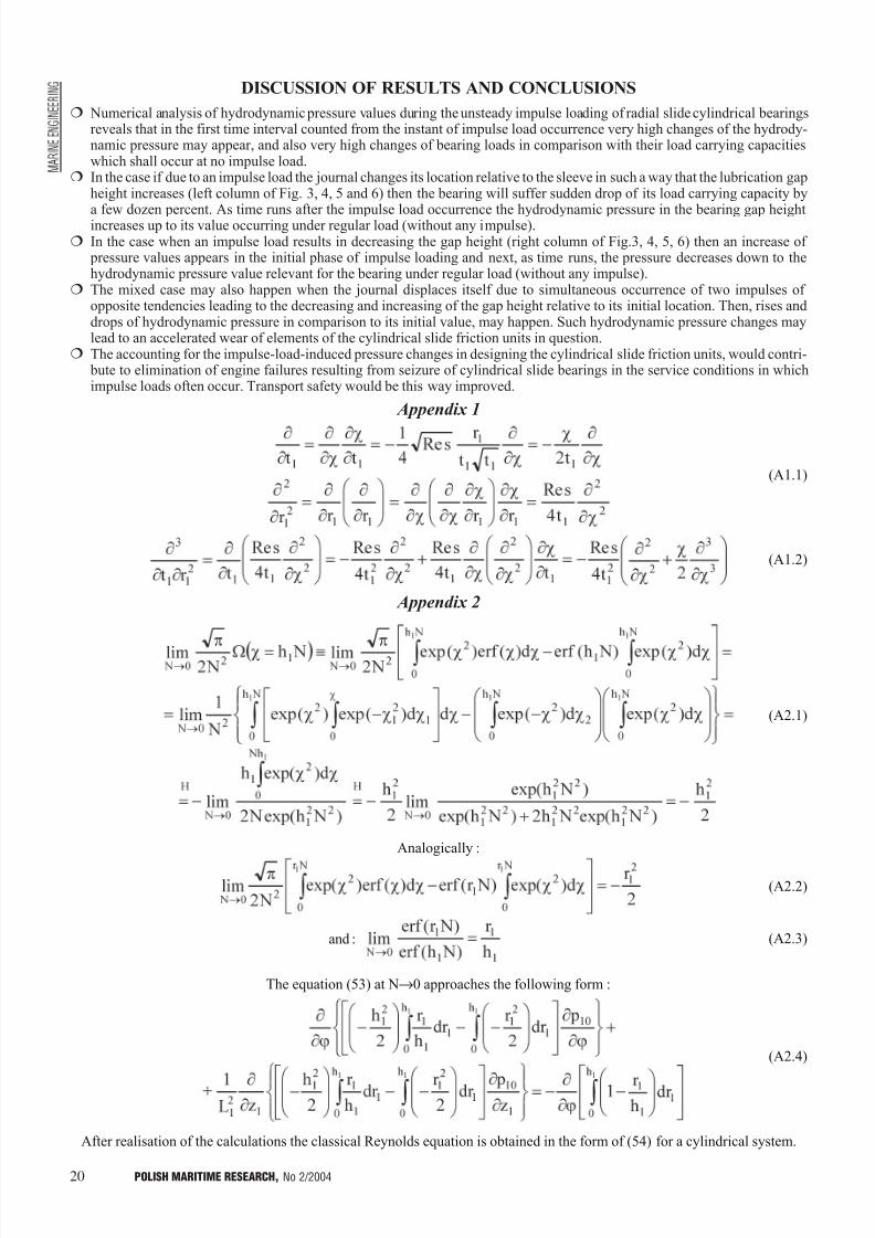
DISCUSSION OF RESULTS AND CONCLUSIONS
¦ Numerical analysis of hydrodynamic pressure values during the unsteady impulse loading of radial slide cylindrical bearingsreveals that in the first time interval counted from the instant of impulse load occurrence very high changes of the hydrody-namic pressure may appear, and also very high changes of bearing loads in comparison with their load carrying capacitieswhich shall occur at no impulse load.
¦ In the case if due to an impulse load the journal changes its location relative to the sleeve in such a way that the lubrication gapheight increases (left column of Fig. 3, 4, 5 and 6) then the bearing will suffer sudden drop of its load carrying capacity by
a few dozen percent. As time runs after the impulse load occurrence the hydrodynamic pressure in the bearing gap heightincreases up to its value occurring under regular load (without any impulse).¦ In the case when an impulse load results in decreasing the gap height (right column of Fig.3, 4, 5, 6) then an increase of
pressure values appears in the initial phase of impulse loading and next, as time runs, the pressure decreases down to thehydrodynamic pressure value relevant for the bearing under regular load (without any impulse).
¦ The mixed case may also happen when the journal displaces itself due to simultaneous occurrence of two impulses of opposite tendencies leading to the decreasing and increasing of the gap height relative to its initial location. Then, rises anddrops of hydrodynamic pressure in comparison to its initial value, may happen. Such hydrodynamic pressure changes maylead to an accelerated wear of elements of the cylindrical slide friction units in question.
¦ The accounting for the impulse-load-induced pressure changes in designing the cylindrical slide friction units, would contri- bute to elimination of engine failures resulting from seizure of cylindrical slide bearings in the service conditions in whichimpulse loads often occur. Transport safety would be this way improved.
Appendix 1
(A1.1)
(A1.2)
Appendix 2
(A2.1)
Analogically :
The equation (53) at N®0 approaches the following form :
(A2.4)
After realisation of the calculations the classical Reynolds equation is obtained in the form of (54) for a cylindrical system.
and : (A2.3)
(A2.2)

7/30/2019 PMRes_2004_2
http://slidepdf.com/reader/full/pmres20042 21/32
21POLISH MARITIME RESEARCH, No 2/2004
Acknowledgement
This scientific work has been financed by Polish State Com-mittee for Scientific Research during the years 2001-2003.
NOMENCLATURE
a - acceleration vector [m/s2]A
1 - Rivlin-Ericksen strain tensors [s-1
]A2 - Rivlin-Ericksen strain tensors [s-2] b - a half of bearing length [m]c - coefficient for controllling gap height changesCz1 , Cz2 , Cz3 , Cz4 , Cj1 , Cj2 , Cj3 , Cj4 - integration constantsDe - Deborah number h - gap height in the cylindrical bearing [m]h1 - dimensionless gap heightI - unit tensor L - tensor of oil velocity vector gradient [s-1]LT - tensor with matrix transpose [s-1]L1 - dimensionless bearing length N - dimensionless number
- estimate of all remaining corrections of velocity
and pressure components p - pressure [Pa] po - characteristic value of hydrodynamic pressure [Pa] p1 - total dimensionless hydrodynamic pressure p10 , p11 , p12 - dimensionless corrections of hydrodynamic
pressureP - load [N]r - radial coordinate [m]r 1 , r 2 - dimensionless radial coordinateR - radius of cylindrical journal [m]Re - Reynold's number s - skew coefficientS - stress tensor [Pa]Str - Strouhal number t - time [s]
to - characteristic time [s]t1 , t2 - dimensionless timeU - tangential journal velocity [m/s]v - velocity vector [m/s]vj , vr , vz - dimensional values of tangential, radial and axial
components of velocity vector, respectively [m/s]vj1 , vr1 , vz1 - dimensionless values of tangential, radial and
axial components of velocity vector, respectivelyvj0S , vr0S , vz0S - dimensionless components of oil velocity vector,
without accounting for changes due to disturbingimpulse
vj1S , vr1S , vz1S , vj2S , vr2S , vz2S - dimensionless corrections of oilvelocity vector components, resulting fromdisturbing impulse impact on a bearing atsufficiently close instant from the impulse
occurrencev10 , v20 - parts of dimensionless velocity vector
components, dependent on shaft rotation, withoutaccounting for disturbing impulse action
v11 , v12 - parts of dimensionless velocity vector components, dependent on shaft rotation, withaccounting for disturbing impulse action
vj03 , vz03 - parts of dimensionless velocity vector components, resulting from pressure gradientinfluence, without accounting for disturbingimpulse action
vj13 , vz13 - parts of dimensionless velocity vector components,resulting from pressure gradient influence, withaccounting for disturbing impulse action
z - longitudinal coordinate [m]
z1 - dimensionless longitudinal coordinatea , b - pseudo-viscosity constants of oil [Pa·s2] g - skew angle
d - a value close zeroe - radial clearanceho - characteristic value of oil dynamic viscosity [Pa·s]l - relative eccentricityr - oil density [kg/m3]j - tangential coordinatec , c1 , c2 - dimensionless coordinatesy - relative radial clearancew - angular journal velocity [s-1]
wo - angular speed of sleeve perturbation [s-1]W , W1 , W2 , W3 - auxiliary functions
BIBLIOGRAPHY
1. Astarita G., Marrucci G.: Principles of non-Newtonian Fluid Mechanics. McGraw Hill Co. London, 1974
2. Böhme G.: On Steady Streaming in Viscoelastic Liquids. Journalof Non-Newtonian Fluid Mechanics, No 44, 1992
3. Girtler J.: Availability of Sea Transport Means. Archives of Transport. Quarterly of Polish Academy of Sciences.Vol.9,iss. 3-4. Warszawa, 1997
4. Girtler J.: Semi-Markov Model of Changes of Safety of Movementsof Sea Ship and Aircrafts. Archives of Transport. Quarterly of Polish Academy of Sciences, Vol.11, iss. 1-2, Warszawa, 1999
5. Knopp K.: Unfinite series (in Polish translated from German)PWN. 1956
6. Miszczak A.: Theoretical study on influence of non-Newtonianoils on operational parameters of stationary loaded radial slidebearings (in Polish). Doctorate thesis. Mining-MetalurgicalAcademy, Kraków, 1998
7. Teipel I., Waterstraat A.: Nichtnewtonische Schmiermittel im Radialgleitlager . Konstruktion, Vol. 32, No 10, 1980
8. Tipei N.: Theory of Lubrication. California, W. A. GrossStanford. University Press. 1962
9. Truesdell. C. A.: First Course in Rational Continuum Mechanics, John Hopkins University/Baltimore, Maryland1972, Piervonaczalnyj Kurs Racionalnoj Mechaniki. MIR.Moskva, 1975
10.Wierzcholski K. Pytko S.: Calculations of cylindrical slidebearings lubricated with oils of non-Newtonian properties (inPolish). Zagadnienia Eksploatacji Maszyn. Quarterly of PolishAcademy of Sciences, Vol. 25, iss. 4 (84), 1990
11.Wierzcholski K.: Mathematical methods in hydrodynamic theoryof lubrication. Technical University of Szczecin, Monography No 511. Szczecin, 1993
12.Wierzcholski K., Krasowski P.: Slide journal bearing lubrication for oil dynamic viscosity changes by pressure and magnetic field . Proc. of II International Scientific TechnicalConference : Explo-Diesel & Gas Turbione 01. Vol. 1. Gdañsk--Miêdzyzdroje-Kopenhaga, 2001
13.Wierzcholski K : Ferromagnetic Turbulent Lubrication for Thermoelasticity Deformations of Bearing Gap. The FifthInternational Congress on Thermal Stresses and Related Topics.
Virginia Polytechnic Institute and State University Blacksburg.2003 Proceedings WA4-3 pp.WA4-3-1-WA4-3-4, Virginia USA14.Zahorski S.: Effect of small amplitude harmonic vibrations on
viscoelastic flows in a plane slider bearing . Arch. Mech,Vol. 34, No 1, 1982
15.Zhang Z., Jiang X.: Analysis of Cylindrical Journal Bearing With Viscoelastic Bush. Transaction of the ASME, Journal of Tribology, Vol. 112, 1990
CONTACT WITH THE AUTHOR
Andrzej Miszczak, D.Sc., M.E.Gdynia Maritime University,
Faculty of Marine Engineering81-225 Gdynia, ul. Morska 81-87e-mail: [email protected]
2
1t
DesO

7/30/2019 PMRes_2004_2
http://slidepdf.com/reader/full/pmres20042 22/32
22 POLISH MARITIME RESEARCH, No 2/2004
A valuable book written by Prof. Karol Grudziñski andDr Eng Wies³aw Jaroszewicz, has been recently published.
The book presents a modern method for the seating of marine and land-based machines and devices on chocks castof EPY resin compound specially developed for this purpo-se. General requirements referring to the seating of machi-nery on foundations (especially those used in shipbuilding)are listed together with relevant evaluation criteria. The pro- perties of resin compounds used for foundation chocks, the background of chocking arrangement design and the techni-
ques used for casting the chocks in place are also outlined.
Many examples of so installed machines and devices aredescribed, illustrating various possible applications of EPYcompound to the seating of new machinery and the repairsof existing one. The results and descriptions of research aimedat finding solutions for many practical problems in this field,constituting a scientific basis of the methods developed for the seating of machines on their foundations, are also given.
The book of 186 pages consistsof the six topical chapters :
1. Characteristics and types of chocking arrangements used
for ship machinery2. The resin compounds used for ship machinery founda-
tion chocks3. Design of machinery chocking arrangements with EPY
compound chocks4. The technology of machinery seating on EPY compo-
und chocks5. Applications of EPY compound chocks for the seating
of machinery - practical examples6. Research on resin compounds used for foundation chocks
(this chapter occupies amost a half of the book and isillustrated with 74 fotoghaphies and drawings)
The attached bibliography contains 83 references. The book is ended with "The chronological list of research re- ports concerning Polish resin compounds used for founda-tion chocks, and their practical application for the seating of machinery"(containing 132 items both published and unpu- blished).
The book is addressed to designers and shipbuildingtechnology specialists as well as the engineers and techni-cians dealing with the design, modernisation and executionof various heavy machinery installations on land. It mayalso be of use for the scientific workers and students of theuniversity faculties engaged in the fields of shipbuildingand offshore technology, machinery design and maintenan-
ce, industrial constructions and the building of roads and bridges.
The first of the authors of the book, Prof. Karol Grudziñ-ski, has worked at the Chair of Mechanics and Principles of Mechanical Design, Faculty of Mechanical Engineering,Technical University of Szczecin. The area of his scientificinterests covers the mechanics of machines, mechanics of contact between real surfaces and tribology, with main fo-cus on experimental research, modelling and calculations of constructional joints. The results of his research has been presented in this book. Prof. Karol Grudziñski is an author and co-author of about 200 scientific papers.
Dr Eng Wies³aw Jaroszewicz, the other author of the book, has been angaged in the machinery seating technolo-gy since the early 1980s. He has owned the Marine ServiceJaroszewicz company since 1990, which has developed theEPY resin compound and carried out machinery seating ope-rations based on its use. He is a co-author of many scientific publications, patents and reports. Over 7500 shipboard andland machines have been installed in the years of 1974 -- 2002 under his supervision and with his cooperation, in-cluding over 1500 main engines of ships. The practical exper-tise gained during this multi-year activity has been compre-hensively presented in the book in question.
This English edition of the book is a translation from the Polish edition of 2002.The book assigned with ISBN 83-87377-94-5 mark, has
been published by ZAPOL Publishing Company, Szczecin.
Seating of machines and devices on foundation
chocks cast of EPY resin compound

7/30/2019 PMRes_2004_2
http://slidepdf.com/reader/full/pmres20042 23/32
23POLISH MARITIME RESEARCH, No 2/2004
INTRODUCTION
Machinery parts and structural elements are frequently sub- jected to simultaneous action of constant and cyclic stresses.In marine floating objects, constant stresses are mainly caused by deadweight and hydrostatic pressure, whereas those enco-untered in machinery systems are produced by torque, thrust,centrifugal force, etc. In the present paper also cyclic stressesinduced by time-varying loads of periodic character are consi-dered.
Each Cartesian component of the cyclic stress can be cha-racterised by its mean value and parameters of its alternating
part. It is important to remember that the total strength of anengineering element is altered if residual stresses are present.Since residual stresses have a similar influence on the fatigue behaviour of materials as that of mechanically imposed con-stant stresses of the same magnitude [1], no distinction will bemade between constant, mean and residual stresses.
In order to ensure a fatigue safe life (theoretically infinite)under bending stress of mean value c b and amplitude a b twoapproaches can be indicated [2]. The first is based on the con-dition :
(1)
where :
(2)
is the amplitude of the equivalent zero mean stress,
Fatigue "safe-life" criterion for metal elementsunder multiaxial constant and periodic loads
Janusz Kolenda
Gdañsk University of Technology
Naval University of Gdynia
ABSTRACT
Periodic stress with Cartesian components given in the form of Fourier series is conside-red. To account for the mean stress effect the generalised Soderberg criterion for ductilematerials is employed. An equivalent stress with synchronous components is defined bymeans of the equivalence conditions based on the average strain energy of distortion. The
fatigue "safe-life" design criterion is formulated which covers the conditions of both static strength and fatigue safety and includes material constants that have simple physical in-terpretation, can be determined by uniaxial tests, are related directly to the applied loadsand can reflect material anisotropy.
Key words : design criteria, multiaxial loading, periodic stress, mean stress effect
Analogous conditions can be applied in the caseof axial force or torsional moment.
In the second approach the effect of mean stress is descri- bed by a "failure diagram" or by one of the empirical equations,such as Goodman's, Gerber's, Soderberg's or Bagci's equation,depending on a given situation [2÷5]. In the following the So-derberg's equation for ductile materials is used in the form :
(3)
where :
B - maximum allowable stress amplitude in fatigue"safe-life" design under asymmetric bending
R e - tensile yield strength.
BACKGROUND
Introducing the safety factor :
(4)
and partial safety factors :
(5)
one obtains from (3) :
(6)
b* b Fa ≤
b b b* b caa ψ+=
−=
e
b b
R
c1FB
ba
Bf =
b
bd
b
es a
Ff
cR
f ==
( )1sd f 1f f −−=y b = 0.1 ¸ 0.2 - the asymmetry sensitivity index at bending
F b - the fatigue limit under fully reversed bending.

7/30/2019 PMRes_2004_2
http://slidepdf.com/reader/full/pmres20042 24/32
24 POLISH MARITIME RESEARCH, No 2/2004
So, the design criterion reads :
(7)
i.e.,
(8)
Here the subscript "s" stands for static
and "d" for dynamic parts of the applied stress.Obviously, the condition (1) concerns exclusively fatigue
endurance of the material subjected to combined constant andcyclic loads, whereas satisfaction of (8) guarantees that not onlythe static strength of the material is not exceeded but also thatthe combination of constant and cyclic loads will not lead tofatigue failure. Another essential point is that the partial safetyfactors in (8) can be analysed and/or influenced separately.Therefore (1) and (2) is not used hereunder.
The explicit forms of (8) read :
(9)
for asymmetric bending,
(10)
for asymmetric push-pull force, and
(11)
for asymmetric torsional moment,where :
(12)
(13)
applicable for steels [4].
Here the subscripts "a", "b" and "t" denote axial, bendingand torsional load cases, respectively, and Fa is the fatigue li-mit under symmetric tension-compression.
The aim of this paper is to extend the use of eqation (8) tomultiaxial non-zero mean periodic stresses. For this purpose itis necessary to determine a reduced stress, equivalent in termsof fatigue performance of the material under the multiaxialstress. For example, in the case of in-phase stress with Carte-sian components :
(14)
such reduced stress can be calculated for ductile metals by means of the average-distortion-energy
strength hypothesis [6] as :
(15)
where its mean value and amplitude are given by :
(16)
(17)
For the sake of brevity the stress components sz(t), syz(t)and szx(t) are dropped. It is noteworthy that in the case of out--of-phase stress components :
(14a)
the average-distortion-energy strength hypothesis yields :
(17a)
According to the aforementioned hypothesis, the reducedstress (15) corresponds to that in an element of the specimenunder uniaxial tension-compression test. Consequently, (10)can be used, which leads to the partial safety factors :
(18)
and to the fatigue "safe-life" criterion :
(19)
With (12), (16) and (18) one gets :
(20)
Since normal stress components can be produced by loadsof different mode (tension, compression, bending), and shear stress components by torsion or shear, and the material mayexhibit certain degree of anisotropy, the following modifica-tion of (20) is suggested [7] :
(21)
Here R x is the yield strength under static load relevant tothe mean stress component cx. The remaining material con-
stants are defined analogously. Equation (21) gives :
(22)
With (13) and (17), the equation (23), similar to (22),can be written for the partial safety factor f d [8] :
(23)
where Fi is the fatigue limit under fully reversed load relevantto the stress amplitude ai. Equations (8), (22) and (23) yield thefollowing criterion of fatigue "safe life" under combined mul-tiaxial constant and in-phase loads [9] :
1f ≥
1f f 1d
1s ≤+ −−
1F
a
R
c
b
b
e
b ≤+
1F
a
R
c
a
a
e
a ≤+
1F
a
R
c
t
t
t
t ≤+
et R 3
1R =
bt F3
1
F =
( ) zx,yz,xy,z,y,xitsinact iii =ω+=σ
( ) tsinact eqeqeq ω+=σ
( )
2/1
2zx
2yz
2xyxz
zyyx2z
2y
2x
eqccc3cc
cccccccc
+++−
+−−++=
( )
2/1
2zx
2yz
2xyxz
zyyx2z
2y
2x
eqaaa3aa
aaaaaaaa
+++−
+−−++=
eq
ad
eq
es a
Ff
cR
f ==
( )
( ) 1a3aaaa
F
1
c3ccccR
1
2/12xyyx
2y
2x
a
2/12xyyx
2y
2x
e
≤+−++
++−+
( )2/1
2xy2
t
yx2y
2x2
e
s cR
1cccc
R
1f
−
+−+=
2/1
2
xy
xy
t
2t
y
y
ex
x
e
2
y
y
e
2
x
x
e
2e
s
cR
R
R
1
cR
R c
R
R
cR R c
R R
R
1
f
−
+
+
−
+
+
=
xy,y,xiR R
cc
R
cf
2/1
i yx
yx
2
i
is =
−
=
−
∑
xy,y,xiFF
aa
F
af
2/1
i yx
yx
2
i
id =
−
=
−
∑

7/30/2019 PMRes_2004_2
http://slidepdf.com/reader/full/pmres20042 25/32
25POLISH MARITIME RESEARCH, No 2/2004
(24)
Equation (24) may be called the generalised Soderberg cri-terion of an infinite fatigue life under non-zero mean in-phasestress.
EQUIVALENT STRESS UNDER MULTIAXIAL CONSTANT
AND PERIODIC LOADS
Let us consider the stress with Cartesian componentsgiven by Fourier series :
(25)
where :ci - mean value of i-th stress componentaip, bip - amplitude and phase angle of p-th term in
Fourier expansion of i-th stress componentw0 = 2p/T0 - fundamental circular frequencyT0 - common period of the stress components.
Guided by the above presented criterion for the stress com- ponents (14), we shall try to model the stress components (25) by the equivalent stress components :
(26)
where :( )eqic - mean value of i-th equivalent stress component
( )i
eqi ,a ϕ - amplitude and phase angle of i-th equivalent
stress component
weq - equivalent circular frequency.
For determination of parameters of the equivalent stresscomponents the theory of energy transformation systems [10]is used. According to this theory, a reduced stress model anda given multiaxial stress can be regarded as equivalent in termsof fatigue life of the material if during the service life the inter-nally and externally dissipated energies per unit volume in the-se two stress states are respectively equal. Under the assump-tion that the externally dissipated energy is proportional to theaverage strain energy of distortion, the following equivalencecondition can be written [11] :
(27)
where :
is the strain energy of distortion per unit volumein the equivalent stress state, and :
is that in the actual stress state, and :
If the condition (27) is fulfilledthen also the following equations are satisfied :
(28)
(29)
When : (30)
where : k - a natural number, is assumedthen (25) through (29) yield :
(31)
(32)
(33)
Of course, in design for an infinite fatigue life
the evaluation of equivalent circular frequency can be avoided.
FATIGUE "SAFE-LIFE" CRITERION
Having determined the parameters of equivalent stress com- ponents, one can make use of the criterion (24) which, in parti-cular, is suitable also for non-zero mean stress with synchrono-us components of the form (26). In this instance one obtains :
(34)
so that the fatigue "safe-life" design criterion for metal ele-ments under multiaxial constant and periodic loads becomes :
(35)
Its extension to three-dimensional cases is straightforward.
1FF
aa
F
a
R R
cc
R
c
2/1
i yx
yx
2
i
i
2/1
i yx
yx
2
i
i
≤
−
+
+
−
∑
∑
( ) ( ) ∫ ∫ φ=φoToT
0o0
eq
o
dttT
1dtt
T
1
( )( )( ) ( )( )( ) ( ) ( )( )
σ+σσ−
+σ+σν+=φ
2eqxy
eqy
eqx
2eqy
2eqx
eq
3E3
1t
( ) ( )2xyyx
2y
2x 3
E3
1t σ+σσ−σ+σ
ν+=φ
( )( )
[ ]( )
∫ ∫ σ=σ
oo T
0
2
io
T
0
2eq
io
dttT
1dtt
T
1
( )( ) ( )( )
( ) ( ) ∫
∫
σσ=
=σσ
o
o
T
0
yx
o
T
0
eqy
eqx
o
dtttT
1
dtttT
1
0eq k ω=ω
( )i
eqi cc =
( )
2/1
1 p
2ip
eqi aa
= ∑
∞
=
( ) ( ) ( )
( )∑∞
=
β−β=
=ϕ−ϕ
1 p
ypxpypxp
yxeq
yeq
x
cosaa
cosaa
E - Young modulusn - Poisson's ratio.
7/30/2019 PMRes_2004_2
http://slidepdf.com/reader/full/pmres20042 26/32
26 POLISH MARITIME RESEARCH, No 2/2004
CONCLUSIONS
¦ The fatigue "safe-life" design criterion covering the condi-tions of both static strength and fatigue safety of metal ele-ments under multiaxial constant and periodic loads, wasformulated.
¦ The presented criterion includes material constants which :have simple physical interpretation, can be determined by
uniaxial tests, are directly related to the applied loads, andcan reflect the material anisotropy.
NOMENCLATURE
aa , a b , at - stress amplitude under asymmetric axial force, bending moment and torsional load, respectively
* ba - amplitude of the equivalent zero mean stress under
asymmetric bendingai , ci - amplitude and mean value of i-th stress component
(i = x, y, z, xy, yz, zx)aeq , ceq - amplitude and mean value of the equivalent stress,
respectively( ) ( )eq
ieq
i c,a - amplitude and mean value of i-th equivalent stresscomponent, respectively
aip - amplitude of p-th harmonic in Fourier expansionof i-th stress component
B - maximum allowable stress amplitude in designfor an infinite fatigue life under asymmetric bending
ca , c b , ct - mean stress value under axial force, bending momentand torsional load, respectively
E - Young modulusf - safety factor f d , f s - partial safety factorsFa , F b , Ft - fatigue limit under fully reversed tension-compression,
bending and torsion, respectivelyFi - fatigue limit under fully reversed load relevant
to the stress amplitude aik - natural number R e - tensile yield strengthR i - yield strength relevant to the mean stress component ciR
t- shear yield strength
t - timeT0 - stress periodbi - phase angle of i-th component of the out-of-phase
stressbip - phase angle of p-th harmonic in Fourier expansion
of i-th stress componentn - Poisson's ratiosi - i-th stress componentseq - equivalent stress
( )eqiσ
- i-th equivalent stress componentji - phase angle of i-th equivalent stress componentf , feq - strain energy of distortion per unit volume in the actual
and equivalent stress states, respectivelyy b - asymmetry sensitivity index in bending
w - circular frequencyw0 - fundamental circular frequency of the actual stressweq - equivalent circular frequency
BIBLIOGRAPHY
1. Osgood C.C.: Fatigue design. Pergamon Press. Oxford, 19822. Kocañda S., Szala J.: Fundamentals of fatigue calculations
(in Polish). PWN, Warszawa, 19973. Almar-Naess A. (Ed.): Fatigue handbook. Offshore steel
structures. Tapir Publishers. Trondheim, 19854. Blake A. (Ed.): Handbook of mechanics, materials and
structures. Wiley & Sons. New York, 19855. Hu Qiao, Xu Hao: Two-parameter nominal stress approach.
Int. J. Fatigue, No 5, 19956. Kolenda J.: Average-distortion-energy strength hypothesis.
Proc. of the 17th Symp. on Fatigue and Fracture Mechanics.Bydgoszcz-Pieczyska, 1998
7. Kolenda J.: Generalised safety factor and reliability index ina multiaxial state of static stress. Marine TechnologyTransactions, Vol. 3, 1992
8. Kolenda J.: Safety factor and reliability index in a general stateof cyclic stress. Marine TechnologyTransactions, Vol. 3, 1992
9. Kolenda J.: A new design criterion of steel elements at multiaxial constant and in-phase loadings. Proc. of the 18thSymp. on Fatigue and Fracture Mechanics. Bydgoszcz--Pieczyska, 2000
10.Cempel C.: Theory of energy transformation systems and their application in diagnostic of operating systems. Applied Math.and Computer Sciences, No 3, 1993
11.Kolenda J.: Application of the theory of energy transformation systems to fatigue assessment of steel elements under multiaxial periodic loading . Marine Technology Transactions, Vol. 12, 2001
CONTACT WITH THE AUTHOR
Janusz Kolenda, Prof.,D.Sc.Faculty of Ocean Engineering
and Ship TechnologyGdañsk University of Technology
Narutowicza 11/1280-952 Gdañsk, POLANDe-mail : [email protected]
Maritime Traffic EngineeringOn 20 and 21 November 2003, 10th International Con-
ference devoted to problems of maritime traffic engine-ering was held in winoujcie on the Baltic sea coast.It was organized by the Institute of Maritime Traffic Engi-neering, Maritime University of Szczecin.
The vast program of the Conference comprised 66 pa- pers 6 of which were presented during the plenary ses-sion, and the remaining during 5 topical sessions.
The following papers were presented
during the plenary session :Ü Extreme parameters of ships intended for entering the
port of winoujcie - by S. Gucma and W. l¹czka(Maritime University of Szczecin)
Ü Mathematical model of ship motion in canals and locks by S. Zaikov, M. Lavrinovsky and V. Zaikov (StateUniversity for Water Communication, St. Petersburg)
Ü Ship as intelligent machine - by R. mierzchalski (Gdy-nia Maritime University)
Ü On necessity of establishing a Polish Institute of Navi- gation following the example of similar institutionsoperating in neighbouring countries - by A. Weintrit(Gdynia Maritime University)
Ü The competences and duties of the officers in thecharge of a navigational watch in the face of coming into operation of the ship's integrated control systems
by Z. Kopacz, W. Morga and J. Urbañski (Naval Uni-versity, Gdynia)
Ü A method for the improving of location accuracy of objects with the use of teledetection data - by J. Sanec-ki, A. Klewski, L. Cwojdziñski, K. Maj and P. Ka-mieñski (Military Engineering Academy, Warsaw)
The authors of the conference papers represented 15scientific research centres including one of Slovakia andone of Russia. The greatest contribution to the conferencematerials (36 papers) was made by the authors of Mariti-
me University of Szczecin. The conference became a com- prehensive review of the interesting research projects con-cerning maritime traffic engineering, carried out in thisuniversity.

7/30/2019 PMRes_2004_2
http://slidepdf.com/reader/full/pmres20042 27/32
27POLISH MARITIME RESEARCH, No 2/2004
INTRODUCTION
An increasing interest has been given to underwater robo-tics in the last years. Currently, it is common to use unmannedunderwater vehicles (UUVs) to accomplish such missions as :inspection of coastal and off-shore structures, cable mainte-nance, as well as hydrographical and biological surveys. In themilitary field they are employed in such tasks as surveillance,intelligence gathering, torpedo recovery and mine counter measures. The main benefits of usage of the UUVs can be the possibility of removing a man from the dangers of the under-sea environment, and of reduction in cost of exploration of underwater space.
There are various categories of the UUVs. The most oftenused are remotely operated vehicles (ROVs). The ROV is usu-ally connected to a surface ship by a tether through which allcommunication is wired. The tethers drag influences motionof the vehicle and may produce significant disturbances andenergy loss. The ROV is equipped with a power transmissionsystem and controlled only by thrusters. Simultaneously thespatial station-keeping or tracking of the underwater vehicle isa difficult task for a human operator, hence a supervisory con-trol has been developed to support its own intelligence andautonomy.
Automatic control of underwater vehicles is a complex pro- blem due to their strongly coupled and highly nonlinear dyna-mic characteristics. Moreover, the dynamic characteristics canchange depending on a chosen vehicles configuration suitable
Jerzy Garus
Naval University, Gdynia
Kinematical control of motionof underwater vehicle
in horizontal plane
ABSTRACT
In the paper presented is a method of designing a fuzzy-logic-based autopilot for control of horizontal motion of an unmanned underwater vehicle. The control systems synthesiswas performed under the assumption that the vehicle can move with variable linear and angular velocities and the quantities possible to be measured are : position and orienta-tion of the vehicle in the inertial reference system. The task of the autopilot was to minimi-
ze the mean squares of deviations from the motion trajectory given in the form of a brokenline defined by the coordinates of successive turning points. To generate control signals
three independent fuzzy PD controllers using the control principles based on the Mac Vicar-Whelans standard base, were applied. For the linguistic variables of each controller appropriate fuzzy sets were selected and linear membership functions of trapezoidal and triangular form were defined. The presented results of the simulation tests performed for the remotely operated underwater vehicle Ukwia³, withand without influence of disturbances resulting from sea current, confirm the proposed approach to becorrect and effective.
Key words : Underwater vehicle, autopilot, fuzzy logic
to its mission. In order to cope with the difficulties the controlsystem should be flexible. An interesting review of classicaland modern techniques adopted to control the dynamic beha-viour of unmanned underwater vehicles was presented in [1,3]. Nowadays fuzzy logic control systems have been successfullyapplied to a wide variety of mechanical systems [2,7,9]. The primary advantage of the fuzzy controllers is the possibility of easy incorporating heuristic knowledge of experts into a con-trol strategy. In this paper a fuzzy autopilot for tracking controlof the ROV is described.
TRACKING CONTROL
The general motion of a marine vehicle of 6 degrees of free-dom (DOF) can be described by the following vectors [3] :
(1)
where :
h - the position and orientation vector in the earth--fixed frame
n - the linear and angular velocity vector in the body-fixed frame
t - the forces and moments acting on the vehicle inthe body-fixed frame.
[ ]
[ ]
[ ]T
T
T
N,M,K ,Z,Y,X
r ,q, p,w,v,u
,,,z,y,x
=
=
ψθφ=
X , Y , Z , K , M , N
h
n
t
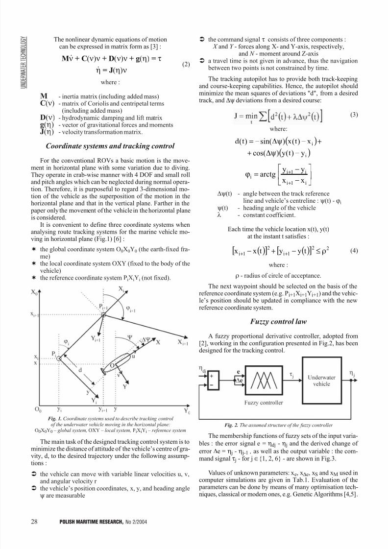
7/30/2019 PMRes_2004_2
http://slidepdf.com/reader/full/pmres20042 28/32
28 POLISH MARITIME RESEARCH, No 2/2004
The nonlinear dynamic equations of motioncan be expressed in matrix form as [3] :
(2)
where :
M - inertia matrix (including added mass)C(n) - matrix of Coriolis and centripetal terms
(including added mass)D(n) - hydrodynamic damping and lift matrixg(h) - vector of gravitational forces and momentsJ(h) - velocity transformation matrix.
Coordinate systems and tracking control
For the conventional ROVs a basic motion is the move-ment in horizontal plane with some variation due to diving.They operate in crab-wise manner with 4 DOF and small rolland pitch angles which can be neglected during normal opera-
tion. Therefore, it is purposeful to regard 3-dimensional mo-tion of the vehicle as the superposition of the motion in thehorizontal plane and that in the vertical plane. Farther in the paper only the movement of the vehicle in the horizontal planeis considered.
It is convenient to define three coordinate systems whenanalysing route tracking systems for the marine vehicle mo-ving in horizontal plane (Fig.1) [6] :
¬ the global coordinate system O0X0Y0 (the earth-fixed fra-me)
¬ the local coordinate system OXY (fixed to the body of thevehicle)
¬ the reference coordinate system PiXiYi (not fixed).
The main task of the designed tracking control system is tominimize the distance of attitude of the vehicles centre of gra-vity, d, to the desired trajectory under the following assump-tions :
Ü the vehicle can move with variable linear velocities u, v,
and angular velocity r Ü the vehicles position coordinates, x, y, and heading angle
y are measurable
Ü the command signal t consists of three components : X and Y - forces along X- and Y-axis, respectively,
and N - moment around Z-axisÜ a travel time is not given in advance, thus the navigation
between two points is not constrained by time.
The tracking autopilot has to provide both track-keepingand course-keeping capabilities. Hence, the autopilot should
minimize the mean squares of deviations "d", from a desiredtrack, and Dy deviations from a desired course:
(3)
where:
( )
( )i
i
y)t(y)cos(
x)t(x)sin()t(d
−ψ∆+
+−ψ∆−=
−
−=ϕ
+
+
i1i
i1ii
xx
yyarctg
Dy(t) - angle between the track referenceline and vehicles centreline : y(t) - ji
y(t) - heading angle of the vehiclel - constant coefficient.
Each time the vehicle location x(t), y(t)at the instant t satisfies :
(4)
where :
r - radius of circle of acceptance.
The next waypoint should be selected on the basis of thereference coordinate system (e.g. Pi+1Xi+1Yi+1) and the vehic-les position should be updated in compliance with the newreference coordinate system.
Fuzzy control law
A fuzzy proportional derivative controller, adopted from[2], working in the configuration presented in Fig.2, has beendesigned for the tracking control.
The membership functions of fuzzy sets of the input varia-
bles : the error signal e = hdj - h j and the derived change of
error De = h j - h j-1 , as well as the output variable : the com-mand signal t j - for j Î{1, 2, 6} - are shown in Fig.3.
Values of unknown parameters: xe, xDe, xS and xM used in
computer simulations are given in Tab.1. Evaluation of the parameters can be done by means of many optimisation tech-niques, classical or modern ones, e.g. Genetic Algorithms [4,5].
( )[ ] ( )[ ] 221i
21i tyytxx ρ≤−+− ++
Fig. 2. The assumed structure of the fuzzy controller
Fig. 1. Coordinate systems used to describe tracking control of the underwater vehicle moving in the horizontal plane:
O0X0Y0 global system, OXY local system, PiXiYi reference system
Mn + C(n)n + D(n)n + g(h) = t
h = J(h)n
·
·

7/30/2019 PMRes_2004_2
http://slidepdf.com/reader/full/pmres20042 29/32
29POLISH MARITIME RESEARCH, No 2/2004
The chosen control rules, taken from the Mac Vicar--Whelans standard base of rules [8], are given in Tab.2.
SIMULATIONS
A simulation study of tracking control has been performedfor an underwater vehicle Ukwia³ designed and built byGdañsk University of Technology for the Polish Navy. TheROV is an open, 1.5 m long frame robot controllable in 4 DOF,fitted with a propulsion system consisted of 6 thrusters.
The vehicle can move in horizontal plane by using four thru-
sters. Every thruster can generate thrust force up to ±250 N.It assures its speed up to u = ±1.2 m/s and v = ±0.6 m/s in X andY direction, respectively. The autopilot in question consists of 3 independent controllers producing the command signals X , Y and N calculated on the basis of the proposed fuzzy law (under the constraints : X £ 500 N, Y £ 150 N and N £ 50 Nm).
The structure of the proposed control systemis presented in Fig.4.
Numerical simulations have been made to confirm validi-ty of the proposed control algorithm under the following as-sumptions:
-the vehicle has to follow the desired route beginning fromthe position and orientation point : (x = 10 m, y = 10 m,y = 0°), passing the target waypoints : (10 m, 90 m, 90°),(30 m, 90 m, 0°), (30 m, 10 m, 270°), (60 m, 10 m, 0°) andending at the point : (60 m, 90 m, 90°)
- the turning point is reached when the vehicle operates wi-thin the 1,5 m radius of circle of acceptance, r
- the initial conditions are the same.
The tracking control simulation results and the courses of command signals for no added environmental disturbances areshown in Fig.5. The real route and position of the vehicle al-most coincides with those desired. Also the quality of course--keeping control is satisfactory (course deviations close to zero).In Fig.6 illustrated is an influence of sea current disturbanceson the vehicles route and course. A clear difference betweenthe desired and real tracking curves is there observed. Altho-ugh the errors of position and course are much bigger than inthe previous case the autopilot is able to cope with the external
disturbances and to reach the turning points with the comman-ded orientation. It should be noted that the last simulations were performed for the sea current speed increased to 0.35 m/s.
Tab. 1. The assumed membership function parameters
Tab. 2. The assumed base of rules
Fig. 3. The assumed membership functions for fuzzy sets of :the error e, derived change of error De, and command signals X,Y,N.
Notation : N - negative, Z - zero, P - positive,S - small, M - medium and B - big
Fig. 4. The block diagram of the track-keeping system Notation : index d - desired value

7/30/2019 PMRes_2004_2
http://slidepdf.com/reader/full/pmres20042 30/32
30 POLISH MARITIME RESEARCH, No 2/2004
Fig. 5. The vehicles tracking curve and course deviations from the desired position and course, for the command signals without interaction of environmental disturbance
Notation : desired real
Fig. 6. The vehicles tracking curve and course deviations from the desired position and course, for the command signals under influence of the sea current of 0.35 m/s speed, and 135°
direction angle
Notation : desired real
y [ m ]
y [ m ]
C o u r s e e r r o r [ d e g ]
C o u r s e [ d e g ]
C o u r s e e r r o r [ d e g ]
C o u r s e [ d e g ]
P o s i t i o n e r r o r [ m ]
P o s i t i o n e r r o r [ m ]
N [ N m ]
Y [ N
]
X [ N ]
N [ N m ]
Y [ N ]
X [ N ]
C o m m a n d
s i g n a l s
C o m m a n d s i g n a l s
· ·
· ·
Time [s]x [m]
Time [s]Time [s]
Time [s]x [m]
Time [s]Time [s]
7/30/2019 PMRes_2004_2
http://slidepdf.com/reader/full/pmres20042 31/32
31POLISH MARITIME RESEARCH, No 2/2004
This is comparable with the average speed of the vehicle. As itwas expected, the guidance was very sensitive to the ratio of thevehicle speed and the current speed. It was observed that thisratio should not be smaller than 2, which is also confirmed in [6].
CONCLUSIONS
v In this paper the waypoint-tracking autopilot using fuzzycontrol, intended for underwater vehicles, has been descri-
bed. The nonlinear model of the ROV Ukwia³ was ap- plied to carry out computer simulations.
v The simulation results obtained by using the control sys-tem design method based on three decoupling fuzzy con-trollers, showed the presented autopilot to be simple anduseful for practical use.
v The main advantage of the proposed solution is its flexibi-lity with regard to the vehicles dynamic model, and its high
performance at relatively large disturbances resulting fromsea current.
NOMENCLATURE
C(v) - matrix of Coriolis and centripetal terms (including addedmass)
d - distance of attitude of the vehicle's centre of gravityfrom the desired trajectory
DOF - degress of freedomD(v) - hydrodynamic damping and lift matrixe - error signalg(h) - vector of gravitational forces and momentsJ - quality indexJ(h) - velocity transformation matrix K - moment around X- axisM - inertia matrix (including added mass) M - moment around Y- axis N - moment around Z- axisOXY - local coordinate system (fixed to the body of the vehicle)O0X0Y0 - global coordinate system (the earth-fixed frame, inertial)
p - angular velocity around X- axisPiXiYi - reference coordinate system (not fixed, connected
with trajectory of motion)q - angular velocity around Y- axisr - angular velocity around Z- axist - timeu - linear velocity along X-axisv - linear velocity along Y- axisw - linear velocity along Z- axisx - vehicle's position coordinate along X0 - axisxe , xDe - coordinates of membership functions of e and De,
respectively, (along axis of abscissae)xS , xM - coordinates of membership functions of t j, (along axis of
abscissae) X - force along X- axisy - vehicle's position coordinate along Y
0- axis
Y - force along Y- axisz - vehicle's position coordinate along Z0 - axis Z - force along Z- axis
De - derived change of error Dy - change of heading angle (deviation from a desired
course)h - vehicle's position and orientation vector in the earth-
-fixed frameq - vehicle's pitch anglel - constant coefficientn - linear and angular velocity vector in the body-fixed
framer - radius of circle of acceptance
t - forces and moments acting on the vehicle in the body--fixed frameji - direction angle of i-th segment of trajectoryf - vehicle's roll angley - vehicle's yaw (heading) angle
BIBLIOGRAPHY
1. Craven P. J., Sutton R., Burns R. S.: Control strategies for unmanned underwater vehicles. Journal of Navigation,
No 51, 19982. Driankov D., Hellendoorn H., Reinfrank M.: An introduction to
fuzzy control. Springer-Verlag. 19933. Fossen T.I.: Guidance and control of ocean vehicles. John Wiley
and Sons. Chichester, 1994
4. Garus J.: Genetic algorithms applied to designing of fuzzycontrollers for underwater vehicle (in Polish). Proc. of 14th
National Conference of Automation. Zielona Góra, 20025. Goldberg D.E.: Genetic algorithms in search, optimisation and
machine learning. Adison-Wesley. 19896. Hansen A.D.: Predictive control and identification: application
to steering dynamic. Ph.D. Dissertation, Technical University of Denmark, Department of Mathematical Modelling. 1996
7. Kacprzyk J.: Multistage fuzzy control. John Wiley and Sons.Chichester. 1997
8. Mac Vicar-Whelan P.J.: Fuzzy sets for man-machineinteractions. International Journal of Man-Machine Studies,
No. 8, 19779. Yager R.R., Zadeh L.A.: An introduction to fuzzy logic
applications in intelligent systems. Kluwer AcademicPublishers, 1991
CONTACT WITH THE AUTHOR
Jerzy GarusDepartment of Mechanicaland Electrical Engineering
Naval Universitymidowicza 69
81-103 Gdynia, POLANDe-mail : [email protected]
A Hundred-Year JubileeOn 7 July of the year 1903 in accordance with the
record in the commemorative book the research establi-shment for water engineering and shipbuilding VWS (Ver-suchanstalt fuer Wasserbau und Schiffbau) officially com-menced its activity in Berlin.
In the course of time it could boast of outstanding - in
the worldwide scale - scientific and technical achievementsin the domain of inland waterways, harbour engineeringand shipbuilding.
On this special occasion the German society of navalarchitects and marine engineers STG (SchiffbautechnischeGesellschaft) held its general assembly on 19 - 22 Novem-
ber 2003 just in Berlin.
Its agenda contained , apart from its organizational partdealing with STG matters, the special session devoted tothe achievements of the VWS, as well as the scientific con-ference carried out within 5 topical sessions.
Scientific workers of the Faculty of Ocean Engineering
and Ship Technology, Gdañsk University of Technologyhave had multi-topical contacts both with the VWS andSTG. Their representative, D.Sc.Eng. Edmund Brzoskatook part in these events.
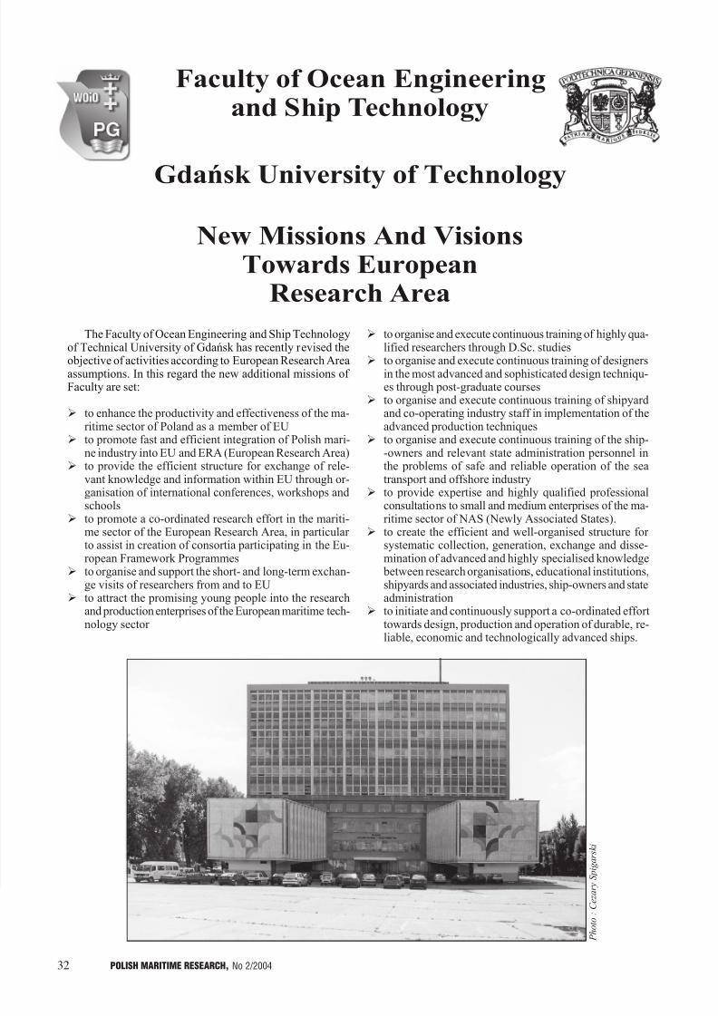
7/30/2019 PMRes_2004_2
http://slidepdf.com/reader/full/pmres20042 32/32
The Faculty of Ocean Engineering and Ship Technologyof Technical University of Gdañsk has recently revised theobjective of activities according to European Research Areaassumptions. In this regard the new additional missions of Faculty are set:
Ø to enhance the productivity and effectiveness of the ma-ritime sector of Poland as a member of EU
Ø to promote fast and efficient integration of Polish mari-ne industry into EU and ERA (European Research Area)
Ø to provide the efficient structure for exchange of rele-vant knowledge and information within EU through or-ganisation of international conferences, workshops andschools
Ø to promote a co-ordinated research effort in the mariti-
me sector of the European Research Area, in particular to assist in creation of consortia participating in the Eu-ropean Framework Programmes
Ø to organise and support the short- and long-term exchan-ge visits of researchers from and to EU
Ø to attract the promising young people into the researchand production enterprises of the European maritime tech-nology sector
Ø to organise and execute continuous training of highly qua-lified researchers through D.Sc. studies
Ø to organise and execute continuous training of designersin the most advanced and sophisticated design techniqu-es through post-graduate courses
Ø to organise and execute continuous training of shipyardand co-operating industry staff in implementation of theadvanced production techniques
Ø to organise and execute continuous training of the ship--owners and relevant state administration personnel inthe problems of safe and reliable operation of the seatransport and offshore industry
Ø to provide expertise and highly qualified professionalconsultations to small and medium enterprises of the ma-ritime sector of NAS (Newly Associated States).
Ø to create the efficient and well-organised structure for systematic collection, generation, exchange and disse-mination of advanced and highly specialised knowledge between research organisations, educational institutions,shipyards and associated industries, ship-owners and stateadministration
Ø to initiate and continuously support a co-ordinated efforttowards design, production and operation of durable, re-liable, economic and technologically advanced ships.
C e z a r
y S p i g a r s k i
Faculty of Ocean Engineeringand Ship Technology
Gdañsk University of Technology
New Missions And VisionsTowards European
Research Area