INSTRUCTION MANUAL PMR446 TRANSCEIVER iF27SR

Welcome message from author
This document is posted to help you gain knowledge. Please leave a comment to let me know what you think about it! Share it to your friends and learn new things together.
Transcript
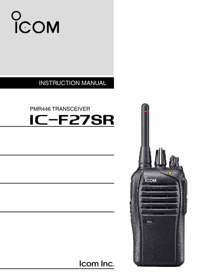
INSTRUCTION MANUAL
PMR446 TRANSCEIVER
iF27SR

i
FOREWORDREAD ALL INSTRUCTIONS carefully and completely before using the transceiver.
SAVE THIS INSTRUCTION MANUAL— This instruction manual contains important operating instructions for the IC-F27SR PMR446 TRANSCEIVER.
This instruction manual includes some functions which are us-able only when they are preprogrammed by your dealer. Ask your dealer for details.
EXPLICIT DEFINITIONSWORD DEFINITION
RDANGER!Personal death, serious injury or an explosion may occur.
RWARNING!Personal injury, fire hazard or electric shock may occur.
CAUTION Equipment damage may occur.
NOTEIf disregarded, inconvenience only. No risk of personal injury, fire or electric shock.
Icom, Icom Inc. and the Icom logo are registered trademarks of Icom Incorpo-rated (Japan) in Japan, the United States, the United Kingdom, Germany, France, Spain, Russia and/or other countries.

ii
COUNTRY CODE LIST• ISO 3166-1
Country Codes Country Codes
1234567891011121314151617
AustriaBelgiumBulgariaCroatiaCzech RepublicCyprusDenmarkEstoniaFinlandFranceGermanyGreeceHungaryIcelandIrelandItalyLatvia
ATBEBGHRCZCYDKEEFIFRDEGRHUISIEITLV
18192021222324252627282930313233
LiechtensteinLithuaniaLuxembourgMaltaNetherlandsNorwayPolandPortugalRomaniaSlovakiaSloveniaSpainSwedenSwitzerlandTurkeyUnited Kingdom
LILTLUMTNLNOPLPTROSKSIESSECHTRGB
iii
PRECAUTIONSR DANGER! NEVER short the terminals of the battery pack.
R DANGER! Use and charge only specified Icom battery packs with Icom radios or Icom chargers. Only Icom battery packs are tested and approved for use with Icom radios or charged with Icom chargers. Using third-party or counterfeit battery packs or chargers may cause smoke, fire, or cause the battery to burst.
R WARNING! NEVER hold the transceiver so that the antenna is very close to, or touching exposed parts of the body, especially the face or eyes, while transmitting. The transceiver will perform best if the microphone is 5 to 10 cm away from the lips and the transceiver is vertical.
R WARNING! NEVER operate the transceiver with a headset or other audio accessories at high volume levels. Hearing experts advise against continuous high volume operation. If you experience a ringing in your ears, reduce the volume level or discontinue use.
R WARNING! NEVER operate the transceiver while driving a vehicle. Safe driving requires your full attention—anything less may result in an accident.
CAUTION: NEVER connect the transceiver to a power source other than the specified battery pack/case. Such a connection will ruin the transceiver.
CAUTION: MAKE SURE the battery pack is securely attached to the transceiver, and that the battery pack is dry before attach-ment. Exposing the inside of the transceiver to water will result in serious damage to the transceiver.
DO NOT push the PTT when not actually desiring to transmit.

iv
DO NOT use or place the transceiver in direct sunlight or in areas with temperatures below –25°C or above +55°C.The basic operations, transmission and reception of the transceiver, are guaranteed within the specified operating temperature range.
DO NOT modify the transceiver. The transceiver warranty does not cover any problems caused by unauthorized modification.
DO NOT use harsh solvents such as benzine or alcohol when cleaning, as they will damage the transceiver surfaces.
BE CAREFUL! The transceiver will become hot when operating it continuously for long periods of time.
KEEP the transceiver away from heavy rain, and never immerse it in water. The transceiver meets IP54* requirements for dust-pro-tection and splash resistance. However, once the transceiver has been dropped, dust-protection and splash resistance cannot be guaranteed because of possible damage to the transceiver’s case or the waterproof seal.* Only when the battery pack/case and jack cover are attached.
MAKE SURE to turn the transceiver power OFF before connect-ing the supplied/optional equipment.
v
TABLE OF CONTENTSFOREWORD ..................................................................................iEXPLICIT DEFINITIONS ................................................................iCOUNTRY CODE LIST ................................................................. iiPRECAUTIONS ............................................................................ iiiTABLE OF CONTENTS .................................................................v
1 ACCESSORIES ....................................................................1–4Supplied accessories ‘ ............................................................1Accessory attachments ‘ .........................................................2
Belt clip ï ..............................................................................2Battery pack/case ï ..............................................................3Jack cover ï ..........................................................................4
2 PANEL DESCRIPTION ........................................................5–9Front, top and side panels ‘ .....................................................5Programmable key functions ‘ .................................................7LED indicator ‘ .........................................................................9
3 OPERATION .....................................................................10–18Turning ON the power ‘ .........................................................10
Battery type selection ï ......................................................10Channel selection ‘ ................................................................11Receiving and transmitting ‘ ..................................................12
ï Preprogrammed frequency and CTCSS tone list (Default) .13Transmitting notes ï ...........................................................14
Setting the microphone gain ‘ ...............................................15Setting the squelch level ‘ .....................................................16Priority A channel selection ‘ .................................................17Auto scan function ‘ ...............................................................17Power save function ‘ ............................................................18

vi
1
2
3
4
5
6
7
8
9
10
11
12
13
14
15
16
17
18
19
20
4 BATTERY CHARGING .....................................................19–29Caution (for the BP-264 ‘ Ni-MH battery) ..............................19Caution (for the BP-265 ‘ Li-ion battery) ...............................21
Battery caution ï ................................................................21Charging caution ï .............................................................23
Battery chargers ‘ ..................................................................24Using the BC-191 to rapid charge the BP-264 ï ................24Using the BC-192 to regular charge the BP-264 ï .............25Using the BC-193 to rapid charge the BP-265 ï ................26 ï Using the BC-197 to rapid charge the BP-264 or BP-265 ..27
5 BATTERY CASE ....................................................................30Optional BP-263 ‘ battery case ...........................................30
6 OPTIONS ..........................................................................31–36BATTERY PACK/CASE ï ....................................................31CHARGERS ï ....................................................................31DC POWER CABLES ï ......................................................32BELT CLIPS ï .....................................................................32OTHER OPTIONS ï ...........................................................33
VOX function ‘ .......................................................................34Optional unit connection ï ..................................................34Turning the VOX function ON or OFF ï ..............................35Setting the VOX gain ï .......................................................36
7 SPECIFICATIONS ............................................................37–38General ï ............................................................................37Transmitter ï .......................................................................37Receiver ï ..........................................................................38Dimensions ï ......................................................................38
8 INDEX ...............................................................................39–40
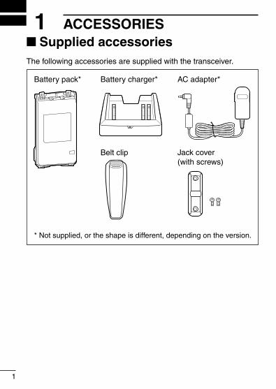
■ Supplied accessoriesThe following accessories are supplied with the transceiver.
Battery pack*
Belt clip Jack cover(with screws)
Battery charger* AC adapter*
* Not supplied, or the shape is different, depending on the version.
1
1 ACCESSORIES

2
1ACCESSORIES
1
2
3
4
5
6
7
8
9
10
11
12
13
14
15
16
17
18
19
20
Accessory attachments ■
D Belt clipTo attach the belt clip:
Slide the belt clip in the direction of the arrow until it locks in ➥
place, and makes a ‘click’ sound.
Battery pack
Belt clip
To detach the belt clip: Remove the battery pack from the transceiver, if it is attached. q
(p. 3) Lift the tab up ( w q), and slide the belt clip in the direction of the arrow (w).
wq
Tab

3
1 ACCESSORIES
Supplied accessories (continued) ■
D Battery pack/caseTo attach the battery pack/case:
Fit the battery pack/case in the direction of the arrow, then q
close.Hook the latch until it makes a ‘click’ sound. w
q
Latch
w
Battery pack/case
To remove the battery pack/case:Unhook the latch (q), and lift up the battery pack/case in the direc-tion of the arrow (w).
q
w
Be careful! The latch is tightly locked, so use caution when re-leasing it. DO NOT use your finger nail. Use the edge of a coin or screwdriver tip to carefully release it.

4
1ACCESSORIES
1
2
3
4
5
6
7
8
9
10
11
12
13
14
15
16
17
18
19
20
NEVER remove or attach the battery pack/case when the trans-ceiver is wet or soiled. This may result in water or dust getting into the transceiver, battery pack/case, and may result in them being damaged.
NOTE: Keep the battery terminals clean. It’s a good idea to reg-ularly clean them.
D Jack coverAttach the jack cover when optional equipment is not used.
To attach the jack cover: Attach the jack cover to the q
[SP MIC] jack.Tighten the screws. w
To detach the jack cover:q Remove the screws with a
Phillips screwdriver.w Detach the jack cover to con-
nect optional equipment.
w
w
w
q
q
q
5
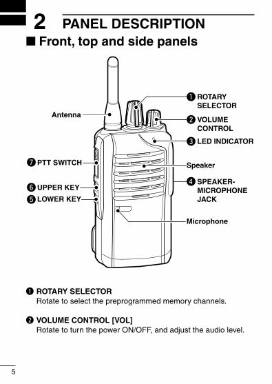
2 PANEL DESCRIPTION ■ Front, top and side panels
Microphone
Speaker
r
w
e
q
y
u
tLOWER KEY
UPPER KEY
PTT SWITCH
Antenna
ROTARYSELECTOR
LED INDICATOR
VOLUMECONTROL
SPEAKER-MICROPHONEJACK
q ROTARY SELECTOR Rotate to select the preprogrammed memory channels.
w VOLUME CONTROL [VOL] Rotate to turn the power ON/OFF, and adjust the audio level.
6
2PANEL DESCRIPTION
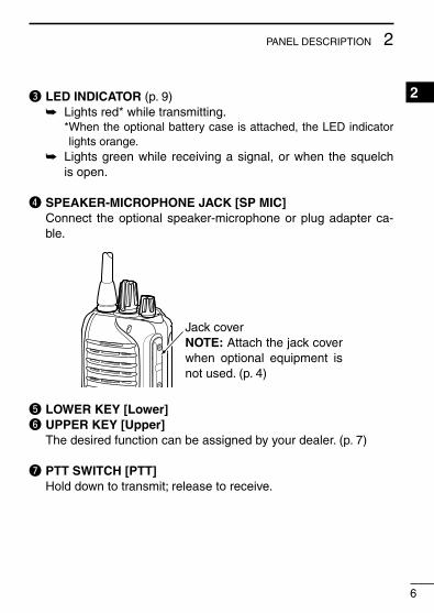
e LED INDICATOR (p. 9)Lights red* while transmitting. ➥
* When the optional battery case is attached, the LED indicator lights orange.
Lights green while receiving a signal, or when the squelch ➥
is open.
r SPEAKER-MICROPHONE JACK [SP MIC] Connect the optional speaker-microphone or plug adapter ca-
ble.
t LOWER KEY [Lower]y UPPER KEY [Upper] The desired function can be assigned by your dealer. (p. 7)
u PTT SWITCH [PTT] Hold down to transmit; release to receive.
1
2
3
4
5
6
7
8
9
10
11
12
13
14
15
16
17
18
19
20
Jack coverNOTE: Attach the jack cover when optional equipment is not used. (p. 4)
7
2 PANEL DESCRIPTION
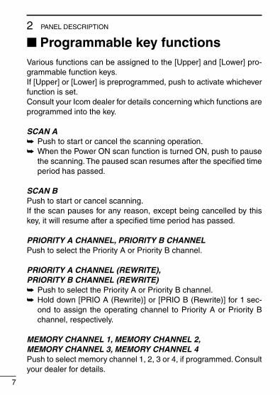
Programmable ■ key functionsVarious functions can be assigned to the [Upper] and [Lower] pro-grammable function keys.If [Upper] or [Lower] is preprogrammed, push to activate whichever function is set.Consult your Icom dealer for details concerning which functions are programmed into the key.
SCAN APush to start or cancel the scanning operation. ➥
When the Power ON scan function is turned ON, push to pause ➥
the scanning. The paused scan resumes after the specified time period has passed.
SCAN BPush to start or cancel scanning.If the scan pauses for any reason, except being cancelled by this key, it will resume after a specified time period has passed.
PRIORITY A CHANNEL, PRIORITY B CHANNELPush to select the Priority A or Priority B channel.
PRIORITY A CHANNEL (REWRITE),PRIORITY B CHANNEL (REWRITE)
Push to select the Priority A or Priority B channel. ➥
Hold down [PRIO A (Rewrite)] or [PRIO B (Rewrite)] for 1 sec- ➥
ond to assign the operating channel to Priority A or Priority B channel, respectively.
MEMORY CHANNEL 1, MEMORY CHANNEL 2,MEMORY CHANNEL 3, MEMORY CHANNEL 4Push to select memory channel 1, 2, 3 or 4, if programmed. Consult your dealer for details.
8
2PANEL DESCRIPTION
1
2
3
4
5
6
7
8
9
10
11
12
13
14
15
16
17
18
19
20
MONITOR Hold down for 1 second to temporarily release the CTCSS* ➥ 1 (or DTCS*2) squelch mute. Push to activate the CTCSS* ➥ 1 (or DTCS*2) squelch mute. Holding down [ ➥ MONI] opens any squelch and deactivates any mute.
*1 Contiuous Tone Coded Squelch System*2 Digital Tone Coded Squelch
LOCKHold down for 1 second to electronically lock all programmable keys except [MONI], [LOCK], [SURVEILLANCE] and [SIREN].
SURVEILLANCEPush to turn the Surveillance function OFF. ➥
Hold down for 1 second to turn the Surveillance function ON. ➥ •WhenthisfunctionisturnedON,thebeepisnotheardandtheLED
does not light, even if a signal is received, or you push a key.
SIRENHold down for 1 second to emit a siren sound.You can use this function for situations other than an emergency alert, such as a security alarm for example.The transceiver will emit the siren sound until you turn OFF the power.

9
2 PANEL DESCRIPTION
■ LED indicatorThe LED indicator indicates the status of various parameters of the transceiver, as follows;(Ref.; R=Red, G=Green, O=Orange)
R* R*
TX Low BATT2 R* R* R* R*
O
O O
G G G G
G G
G G G G G G G G
R G R G R G R G R G R G R G R G
R O R O R O R O R O R O R O R O
G
G G
Clone Err
Clone TX/RX
Low BATT1
Low BATT2
Busy
F/S Scan
Cal l LED Bl ink
Cal l LED ON
TX Low BATT1
R * TX
•TX:LightsRedwhiletransmittingasignal.
•RX:LightsGreenwhilereceivingasignal.
•Fast/Slowscan:BlinkswhentheFast/Slowscanisactivated.
•LowBattery1:Youshouldchargethebattery.(blinksslowly)
•LowBattery2:Youmustchargethebattery.(blinksfast)
•TXlowBattery2:VeryLowBatterywasdetectedduringtransmit.
•ChannelError:Anon-programmedchannelisselected.
* Lights (or blinks) orange when the optional battery case is attached.
•TXlowBattery1:LowBatterywasdetectedduringtransmit.
10
3OPERATION1
2
3
4
5
6
7
8
9
10
11
12
13
14
15
16
17
18
19
20
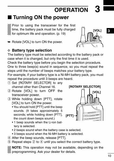
■ Turning ON the powerPrior to using the transceiver for the first time, the battery pack must be fully charged for optimum life and operation. (p. 19)
Rotate [VOL] to turn ON the power. ➥
D Battery type selectionThe battery type must be selected according to the battery pack or case when it is changed, but only the first time it is used. Check the battery type before you begin the selection procedure.One to three beep(s) sound in sequence, so you must repeat the steps until the number of beeps matches your battery type.For example, if your battery type is a Ni-MH battery pack, you must repeat the procedure until 3 beeps are heard.
Set q [ROTARY SELECTOR] to any channel other than Channel 16. Rotate [VOL] to t w urn OFF the transceiver power. While holding down [PTT], rotate e
[VOL] to turn ON the power. •Youshouldhold[PTT]untilthebeep
sounds. (It takes approximately 5 seconds; while holding down [PTT], the count down beeps sound.)
•1beepsoundswhentheLi-ionbat-tery is selected.
•2beepssoundwhenthebatterycaseisselected. •3beepssoundwhentheNi-MHbatteryisselected.
After the beep sounds, release [PTT]. r
Repeat steps t w to r until you select the correct battery type.
NOTE: This operation may not be available, depending on the preprogramming. Ask your dealer for details.
[VOL]
[VOL]
[PTT]
[ROTARY SELECTOR]

■ Channel selectionSeveral types of channel selecting methods are available. They may differ, according to your system set up.
Toselectadesiredoperatingchannel,dooneofthefollowing:•Rotate[ROTARYSELECTOR].•Pushoneofmemorychannelkeys,[MR-CH1]to[MR-CH4].
AUTOMATIC SCAN TYPE:Selecting a channel is not necessary for this type. When turning the power ON, the transceiver automatically starts scanning. Scanning stops when a signal is received, and then the channel is set.
NOTE: If the Move to Priority A channel at Power ON function (p. 17) is turned ON, the transceiver does not start scanning at power ON, and the Priority A channel is automatically selected.
11
3 OPERATION
12
3OPERATION
1
2
3
4
5
6
7
8
9
10
11
12
13
14
15
16
17
18
19
20
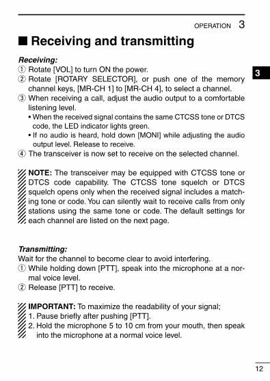
Receiving and transmitting ■
Receiving:Rotate [VOL] to turn ON the power. q
Rotate [ROTARY SELECTOR], or push one of the memory w
channel keys, [MR-CH 1] to [MR-CH 4], to select a channel. When receiving a call, adjust the audio output to a comfortable e
listening level. •WhenthereceivedsignalcontainsthesameCTCSStoneorDTCS
code, the LED indicator lights green. •Ifnoaudioisheard,holddown[MONI]whileadjustingtheaudio
output level. Release to receive. The transceiver is now set to receive on the selected channel. r
NOTE: The transceiver may be equipped with CTCSS tone or DTCS code capability. The CTCSS tone squelch or DTCS squelch opens only when the received signal includes a match-ing tone or code. You can silently wait to receive calls from only stations using the same tone or code. The default settings for each channel are listed on the next page.
Transmitting:Wait for the channel to become clear to avoid interfering.
While holding down [PTT], speak into the microphone at a nor- q
mal voice level.Release [PTT] to receive. w
IMPORTANT: To maximize the readability of your signal;1. Pause briefly after pushing [PTT].2. Hold the microphone 5 to 10 cm from your mouth, then speak
into the microphone at a normal voice level.
13
3 OPERATION
Receiving and transmitting (continued) ■
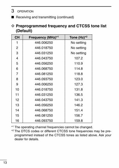
D Preprogrammed frequency and CTCSS tone list (Default)
CH Frequency (MHz)*1 Tone (Hz)*2
1 446.006250 No setting
2 446.018750 No setting
3 446.031250 No setting
4 446.043750 107.2
5 446.056250 110.9
6 446.068750 114.8
7 446.081250 118.8
8 446.093750 123.0
9 446.006250 127.3
10 446.018750 131.8
11 446.031250 136.5
12 446.043750 141.3
13 446.056250 146.2
14 446.068750 151.4
15 446.081250 156.7
16 446.093750 159.8
*1 The operating channel frequencies cannot be changed.*2 The DTCS codes or different CTCSS tone frequencies may be pre-
programmed instead of the CTCSS tones as listed above. Ask your dealer for details.
14
3OPERATION
1
2
3
4
5
6
7
8
9
10
11
12
13
14
15
16
17
18
19
20
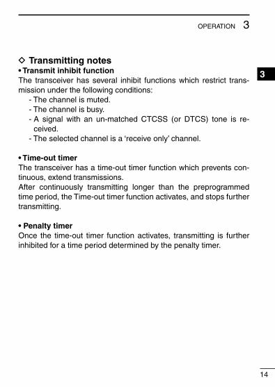
D Transmitting notes• Transmit inhibit functionThe transceiver has several inhibit functions which restrict trans-missionunderthefollowingconditions: - The channel is muted. - The channel is busy. - A signal with an un-matched CTCSS (or DTCS) tone is re-
ceived. - The selected channel is a ‘receive only’ channel.
• Time-out timerThe transceiver has a time-out timer function which prevents con-tinuous, extend transmissions. After continuously transmitting longer than the preprogrammed time period, the Time-out timer function activates, and stops further transmitting.
• Penalty timerOnce the time-out timer function activates, transmitting is further inhibited for a time period determined by the penalty timer.
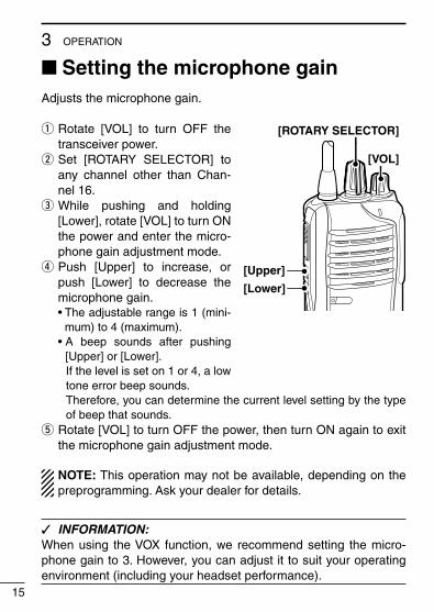
■ Setting the microphone gainAdjusts the microphone gain.
Rotate [VOL] to turn OFF the q
transceiver power. Set [ROTARY SELECTOR] to w
any channel other than Chan-nel 16. While pushing and holding e
[Lower], rotate [VOL] to turn ON the power and enter the micro-phone gain adjustment mode. Push [Upper] to increase, or r
push [Lower] to decrease the microphone gain.
•Theadjustablerangeis1(mini-mum) to 4 (maximum).
•A beep sounds after pushing[Upper] or [Lower].
If the level is set on 1 or 4, a low tone error beep sounds.
Therefore, you can determine the current level setting by the type of beep that sounds.
Rotate [VOL] to turn OFF the power, then turn ON again to exit t
the microphone gain adjustment mode.
NOTE: This operation may not be available, depending on the preprogramming. Ask your dealer for details.
INFORMATION: ✓
When using the VOX function, we recommend setting the micro-phone gain to 3. However, you can adjust it to suit your operating environment (including your headset performance).
15
3 OPERATION
[Upper]
[VOL]
[ROTARY SELECTOR]
[Lower]
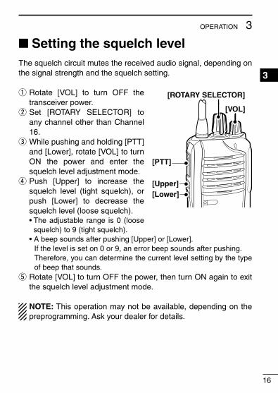
■ Setting the squelch levelThe squelch circuit mutes the received audio signal, depending on the signal strength and the squelch setting.
Rotate [VOL] to turn OFF the q
transceiver power. Set [ROTARY SELECTOR] to w
any channel other than Channel 16. While pushing and holding [PTT] e
and [Lower], rotate [VOL] to turn ON the power and enter the squelch level adjustment mode. Push [Upper] to increase the r
squelch level (tight squelch), or push [Lower] to decrease the squelch level (loose squelch).
•Theadjustable range is0 (loosesquelch) to 9 (tight squelch).
•Abeepsoundsafterpushing[Upper]or[Lower]. If the level is set on 0 or 9, an error beep sounds after pushing. Therefore, you can determine the current level setting by the type
of beep that sounds. Rotate [VOL] to turn OFF the power, then turn ON again to exit t
the squelch level adjustment mode.
NOTE: This operation may not be available, depending on the preprogramming. Ask your dealer for details.
16
3OPERATION
1
2
3
4
5
6
7
8
9
10
11
12
13
14
15
16
17
18
19
20
[VOL]
[Upper]
[ROTARY SELECTOR]
[PTT]
[Lower]
■ Priority A channel selectionDepending on the preprogramming, the Priority A channel is se-lected each time the transceiver power is turned ON.
■ Auto scan functionThe Auto scan function sequentially scans from the selected chan-nel. Scanning automatically searches for signals and makes it eas-ier for you to find stations to contact or to just listen to.
Set [ROTARY SELECTOR] to any channel that the Auto scan q
function is ON.Scan starts automatically. w
•TheLEDindicatorslowlyblinksgreen. •Whenreceivingasignal,scanpausesuntilthesignaldisappears.
17
3 OPERATION

■ Power save functionThe power save function reduces the current drain to conserve bat-tery power.•Depending on the preprogramming, the power save function is au-
tomatically turned ON when no operation is performed or no signal is received for the preprogrammed time period. Ask your dealer for details.
18
3OPERATION
1
2
3
4
5
6
7
8
9
10
11
12
13
14
15
16
17
18
19
20
19
4 BATTERY CHARGING ■ Caution (for the BP-264 ni-mh battery)
R DANGER! NEVER short terminals (or charging terminals) of the battery pack. Also, current may flow into nearby metal objects such as a necklace, so be careful when placing battery packs (or the transceiver) in handbags, etc.Simply carrying with or placing near metal objects such as a neck-lace, etc. may cause shorting. This may damage not only the bat-tery pack, but also the transceiver.
R DANGER! NEVER incinerate used battery packs. Internal bat-tery gas may cause an explosion.
R DANGER! NEVER immerse the battery pack in water. If the bat-tery pack becomes wet, be sure to wipe it dry BEFORE attaching it to the transceiver.
CAUTION: Always use the battery within the specified temperature range for the transceiver (–25˚C to +55˚C) and the battery itself (–5˚C to +65˚C). Using the battery out of its specified temperature range will reduce the battery’s performance and battery life.
CAUTION: Shorter battery life could occur if the battery is left com-pletely discharged, or in an excessive temperature environment (above +55˚C) for an extended period of time. If the battery must be left unused for a long time, it must be detached from the radio after charging. Keep it safely in a cool dry place at the following temperaturerange: –20˚C to +45˚C (up to a month) –20˚C to +35˚C (up to six months) –20˚C to +25˚C (up to a year*)* We recommend charging the battery pack every 6 months.
Clean the battery terminals to avoid rust or misscontact.
Keep the battery terminals clean. It’s a good idea to regularly clean them.

20
4BATTERY CHARGING
1
2
3
4
5
6
7
8
9
10
11
12
13
14
15
16
17
18
19
20
If your Ni-MH battery pack seems to have no capacity, even after being charged, completely discharge it by leaving the power ON overnight. Then, fully charge the battery pack again. If the battery pack still does not retain a charge (or only very little charge), a new battery pack must be purchased. (p. 31)Prior to using the transceiver for the first time, the battery pack must be fully charged for optimum life and operation.•Recommendedtemperaturerangeforcharging: between +10°C
and+40°C(rapidcharge:withBC-191/BC-197)orbetween0°Cand+45°C(regularcharge:withBC-192)
•Use the supplied charger or optional charger (BC-191/BC-197for rapid charging, BC-192 for regular charging) only. NEVER use other manufacturers’ chargers.
The battery pack contains a rechargeable battery.Charge the battery pack before first operating the transceiver, or when the battery pack becomes exhausted.If you want to prolong the battery life, the following points should beobserved:•Avoid over charging. The charging time period by the BC-192
should be less than 48 hours.•Usethebatterypackuntilitbecomesalmostcompletelyexhaust-
ed, under normal conditions.
■ Caution (for the BP-265 li-ion battery)
Misuse of Li-ion batteries may result in the following hazards:smoke, fire, or the battery may rupture. Misuse can also cause damage to the battery or degradation of battery performance.
R DANGER! Use and charge only specified Icom battery packs with Icom radios or Icom chargers. Only Icom battery packs are tested and approved for use with Icom radios or charged with Icom chargers. Using third-party or counterfeit battery packs or chargers may cause smoke, fire, or cause the battery to burst.
Battery caution DR DANGER! DO NOT hammer or otherwise impact the battery. Do not use the battery if it has been severely impacted or dropped, or if the battery has been subjected to heavy pressure. Battery damage may not be visible on the outside of the case. Even if the surface of the battery does not show cracks or any other damage, the cells inside the battery may rupture or catch fire.
R DANGER! NEVER use or leave battery packs in areas with tem-peratures above +60˚C. High temperature buildup in the battery, such as could occur near fires or stoves, inside a sun heated car, or in direct sunlight may cause the battery to rupture or catch fire. Excessive temperatures may also degrade battery performance or shorten battery life.
R DANGER! DO NOT expose the battery to rain, snow, seawater, or any other liquids. Do not charge or use a wet battery. If the bat-tery gets wet, be sure to wipe it dry before using. The battery is not waterproof.
21
4 BATTERY CHARGING
22
4BATTERY CHARGING
1
2
3
4
5
6
7
8
9
10
11
12
13
14
15
16
17
18
19
20
R DANGER! NEVER incinerate used battery packs, since internal battery gas may cause them to rupture, or may cause an explo-sion.
R DANGER! NEVER solder the battery terminals or NEVER mod-ify the battery pack. This may cause heat generation, and the bat-tery may rupture, emit smoke or catch fire.
R DANGER! Use the battery only with the transceiver for which it is specified. Never use a battery with any other equipment, or for any purpose that is not specified in this instruction manual.
R DANGER! If fluid from inside the battery gets in your eyes, blind-ness can result. Rinse your eyes with clean water, without rubbing them, and see a doctor immediately.
R WARNING! Immediately stop using the battery if it emits an ab-normal odor, heats up, or is discolored or deformed. If any of these conditions occur, contact your Icom dealer or distributor.
R WARNING! Immediately wash, using clean water, any part of the body that comes into contact with fluid from inside the battery.
R WARNING! NEVER put the battery in a microwave oven, high-pressure container, or in an induction heating cooker. This could cause a fire, overheating, or cause the battery to rupture.
CAUTION: Always use the battery within the specified temperature range for the transceiver (–25˚C to +55˚C) and the battery itself (–20˚C to +60˚C). Using the battery out of its specified temperature range will reduce the battery’s performance and battery life.

23
4 BATTERY CHARGING
Caution (for the BP-265 ■ Li-ion battery) (continued)
CAUTION: Shorter battery life could occur if the battery is left fully charged, completely discharged, or in an excessive temperature environment (above +50˚C) for an extended period of time. If the battery must be left unused for a long time, it must be detached from the radio after discharging. You may use the battery until the remaining capacity is about half, then keep it safely in a cool dry place within the temperature range asshownbelow: –20˚C to +50˚C (up to a month) –20˚C to +35˚C (up to three months) –20˚C to +20˚C (up to a year)
Charging caution DR DANGER! NEVER charge the battery pack in areas with ex-tremely high temperatures, such as near fires or stoves, inside a sun heated car, or in direct sunlight. In such environments, the safety/protection circuit in the battery will activate, causing the bat-tery to stop charging.
R WARNING! DO NOT charge or leave the battery in the battery charger beyond the specified time for charging. If the battery is not completely charged by the specified time, stop charging and re-move the battery from the battery charger. Continuing to charge the battery beyond the specified time limit may cause a fire, overheat-ing, or the battery may rupture.
R WARNING! NEVER insert the transceiver (battery attached to the transceiver) into the charger if it is wet or soiled. This could corrode the battery charger terminals or damage the charger. The charger is not waterproof.
CAUTION: DO NOT charge the battery outside of the specified temperaturerange:BC-193/BC-197(+10˚Cto+40˚C).Icomrecom-mends charging the battery at +20˚C. The battery may heat up or rupture if charged out of the specified temperature range. Addition-ally, battery performance or battery life may be reduced.
24
4BATTERY CHARGING
1
2
3
4
5
6
7
8
9
10
11
12
13
14
15
16
17
18
19
20
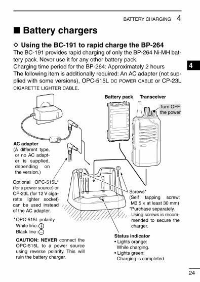
■ Battery chargers D Using the BC-191 to rapid charge the BP-264
The BC-191 provides rapid charging of only the BP-264 Ni-MH bat-tery pack. Never use it for any other battery pack.ChargingtimeperiodfortheBP-264:Approximately2hoursThefollowingitemisadditionallyrequired:AnACadapter(notsup-plied with some versions), OPC-515L dc power cable or CP-23L cigarette lighter cable.
Status indicator• Lights orange: While charging.• Lights green: Charging is completed.
AC adapter(A different type, or no AC adapt-er is supplied, depending on the version.)
OPC-515L polarityWhite line:Black line :
CAUTION: NEVER connect the OPC-515L to a power source using reverse polarity. This will ruin the battery charger.
*
Battery pack Transceiver
Turn OFFthe power
Optional OPC-515L* (for a power source) or CP-23L (for 12 V ciga-rette lighter socket) can be used instead of the AC adapter.
Screws*(Self tapping screw:M3.5 × at least 30 mm)
*Purchase separately. Using screws is recom-mended to secure the charger.

25
4 BATTERY CHARGING
Battery chargers (continued) ■
D Using the BC-192 to regular charge the BP-264The BC-192 provides regular charging of only the BP-264 Ni-MH battery pack. Never use it for any other battery pack.Charging time period for the BP-264 (with BC-147S) :Approximately16hours(at16V)Thefollowingitemisadditionallyrequired:AnACadapter(notsup-plied with some versions) or OPC-515L dc power cable.
AC adapter(A different type, or no AC adapt-er is supplied, depending on the version.)
Charging time period differs depending on the input voltage.12 V13.8 V16 V
: Approx. 36 hours: Approx. 21 hours: Approx. 16 hours
OPC-515L polarityWhite line:Black line :
CAUTION: NEVER connect the OPC-515L to a power source using reverse polarity. This will ruin the battery charger.
*
Battery pack Transceiver
Turn OFFthe power
Optional OPC-515L* (for a power source) can be used instead of the AC adapter. Screws*
(Self tapping screw:M3.5 × at least 30 mm)
*Purchase separately. Using screws is recom-mended to secure the charger.
Status indicatorLights green while charging.
NOTE:The charge indicator will not go out even after a battery pack is fully charged.

26
4BATTERY CHARGING
1
2
3
4
5
6
7
8
9
10
11
12
13
14
15
16
17
18
19
20
D Using the BC-193 to rapid charge the BP-265The BC-193 provides rapid charging of only the BP-265 Li-ion bat-tery pack. Never use it for any other battery pack.ChargingtimeperiodfortheBP-265:Approximately2.5hours
Thefollowingitemisadditionallyrequired:AnACadapter(notsup-plied with some versions), OPC-515L dc power cable or CP-23L cigarette lighter cable.
Status indicator• Lights orange: While charging.• Lights green: Charging is completed.
AC adapter(A different type, or no AC adapt-er is supplied, depending on the version.)
OPC-515L polarityWhite line:Black line :
CAUTION: NEVER connect the OPC-515L to a power source using reverse polarity. This will ruin the battery charger.
*
Battery pack Transceiver
Turn OFFthe power
Optional OPC-515L* (for a power source) or CP-23L (for 12 V ciga-rette lighter socket) can be used instead of the AC adapter.
Screws*(Selftappingscrew:M3.5× at least 30 mm)
*Purchase separately. Using screws is recom-mended to secure the charger.

27
4 BATTERY CHARGING
Battery chargers (continued) ■
D Using the BC-197 to rapid charge the BP-264 or BP-265
The BC-197 rapidly charges up to six battery packs.ChargingtimefortheBP-264:Approximately2hoursChargingtimefortheBP-265:Approximately2.5hours
Thefollowingadditionalitemisrequired:•AnACadapter(notsuppliedwithsomeversions)ortheOPC-656dc
power cable
(An AC adapter isnot supplied withsome versions.)
AC adapter
(Connect to a DC power supply; 12 to 16 V/at least 7 A)Red line : + Black line : _
TransceiverBattery pack
Turn OFF the power
Status indicator(each indicator independently functions)
OPC-656 (DC power cable)
The charger adapters are in-stalled in each slot. The shape of charger adapter depends on the version of the BC-197.
28
4BATTERY CHARGING
1
2
3
4
5
6
7
8
9
10
11
12
13
14
15
16
17
18
19
20
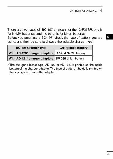
There are two types of BC-197 chargers for the IC-F27SR; one is for Ni-MH batteries, and the other is for Li-ion batteries.Before you purchase a BC-197, check the type of battery you are using, and then be sure to choose the suitable charger type.
BC-197 Charger Type Chargeable Battery
With AD-120* charger adapters BP-264 Ni-MH battery
With AD-121* charger adapters BP-265 Li-ion battery
* The charger adapter type, AD-120 or AD-121, is printed on the inside bottom of the charger adapter. The type of battery it holds is printed on the top right corner of the adapter.
29
4 BATTERY CHARGING
Battery chargers (continued) ■
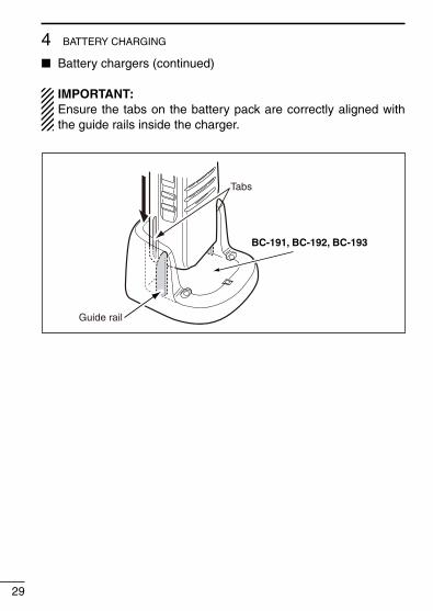
IMPORTANT: Ensure the tabs on the battery pack are correctly aligned with the guide rails inside the charger.
Guide rail
Tabs
BC-191, BC-192, BC-193

■ Optional BP-263 battery case
When using the optional battery case, install 6 × AA (LR6) size alkaline batteries, as illustrated below.
Remove the battery case if it is attached. (p. 3) q
Install 6 w × AA (LR6) size alkaline batteries, as shown below. •Installonlyalkalinebatteries. •Besuretoobservethecorrectpolarity.
Reattach the battery case. (p. 3) e
CAUTION:•When installing batteries, make sure they are all the same
brand, type and capacity. Also, do not mix new and old batter-ies together.
•Keepthebatteryterminalsclean.It’sagoodideatoregularlyclean them.
•Neverincinerateusedbatterycellssinceinternalbatterygasmay cause them to rupture.
•Neverexposeadetachedbatterycasetowater.Ifthebatterycase gets wet, be sure to wipe it dry before using it.
•Neverusebatterieswhoseinsulatedcoverisdamaged.
NOTE: When the optional battery case is attached, the battery type must be selected as “Battery case operation” when turning the transceiver ON. See page 10 for details.
30
5BATTERY CASE1
2
3
4
5
6
7
8
9
10
11
12
13
14
15
16
17
18
19
20
Be careful! The negative terminals of the battery case protrude from the body, so pay attention not to injure your fingers when inserting the batteries.

BATTERY PACK/CASE DBattery
pack/caseVoltage Capacity Battery life*1
BP-263Battery case for
AA (LR6) × 6 alkaline—*2
BP-264 7.2 V 1400 mAh (typ.) 24.8 hrs.
BP-265 7.4 V1900 mAh (min.)2000 mAh (typ.)
35.3 hrs.
*1 When the power save function is turned ON, and the operating time is calculated under the following conditions;
TX:RX:standby=5:5:90*2 The average operating time depends on the alkaline cells used.
CHARGERS D• BC-191 desktop charger + BC-123SE ac adapter
For rapid charging of the Ni-MH battery pack. An AC adapter may be supplied with the charger, depending on the version.
ChargingtimeperiodfortheBP-264:Approximately2hours.
• BC-192 desktop charger + BC-147SE ac adapter
For regular charging of the Ni-MH battery pack. An AC adapter may be supplied with the charger, depending on the version.
ChargingtimeperiodfortheBP-264:Approximately16hours. (at 16 V)
• BC-193 desktop charger + BC-123SE ac adapter
For rapid charging of the Li-ion battery pack. An AC adapter may be supplied with the charger, depending on the version.
ChargingtimeperiodfortheBP-265:Approximately2.5hours.
31
6 OPTIONS

32
6OPTIONS
1
2
3
4
5
6
7
8
9
10
11
12
13
14
15
16
17
18
19
20
• BC-197 multi-charger + BC-157SE ac adapter
For rapid simultaneously charging of up to six battery packs. An AC adapter may be supplied with the charger, depending on the version. There are two types of BC-197 chargers for the IC-F27SR.
BC-197 Charger Type Chargeable Battery Charging time
With AD-120* BP-264 Ni-MH battery Approx. 2 hrs.
With AD-121* BP-265 Li-ion battery Approx. 2.5 hrs.
* Either AD-120 or AD-121 charger adapters are installed in the BC-197, depending on the chargeable battery pack.
DC POWER CABLES D• CP-23L cigarette lighter cable
Allows charging of the battery pack through a 12 V cigarette light-er socket. (For BC-191/BC-193)
• OPC-515L/OPC-656 dc power cable
For charging of the battery packs using a 12 V DC power source instead of the AC adapter.
OPC-515L:BC-191/BC-192/BC-193 OPC-656 :BC-197
BELT CLIPS D• MB-124 belt clip
Exclusive alligator-type belt clip.

33
6 OPTIONS
OTHER OPTIONS D• HM-158L/HM-159L speaker-microphone
Combination speaker-microphone that provides convenient op-eration while hanging the transceiver on your belt.
• HS-94/HS-95/HS-97 headset + OPC-2004 plug adapter cable
HS-94 :Earhooktype HS-95 :Neck-armtype HS-97 :Throatmicrophone OPC-2004:Allowsyou to connect theHS-94,HS-95orHS-97
to the transceiver. After connection, the VOX function can be used.
Approved Icom optional equipment is designed for optimal performance when used with an Icom transceiver.Icom is not responsible for the destruction or damage to an Icom trans-ceiver in the event the Icom transceiver is used with equipment that is not manufactured or approved by Icom.
Some options may not be available in some countries. Please ask your dealer for details.

34
6OPTIONS
1
2
3
4
5
6
7
8
9
10
11
12
13
14
15
16
17
18
19
20
■ VOX functionThe transceiver has a VOX (voice operated transmission) function, which allows you hands-free operation.In addition, an HS-94, HS-95 or HS-97 headset and an OPC-2004 plug adapter cable are required.•TheVOXfunctionstartstransmissionwhenyouspeakintothemicro-
phone, then automatically returns to receive when you stop speaking without needing to push or release the PTT switch.
D Optional unit connectionRotate [VOL] to turn OFF the transceiver power. q
Remove the jack cover. (p. 4) w
Connect an optional HS-94, HS-95 or HS-97 headset and OPC- e
2004, as illustrated below.
HS-94
OPC-2004
q
w
e
[VOL]

35
6 OPTIONS
VOX function (continued) ■
D Turning the VOX function ON or OFFThe VOX function can be turned ON or OFF when turning the trans-ceiver power ON.
Rotate [VOL] to turn OFF the q
transceiver power. Set [ROTARY SELECTOR] to w
any channel other than Chan-nel 16. While holding down [Upper], e
turn ON the transceiver power to switch the VOX function ON or OFF.
•1 beep sounds when the VOXfunction is turned OFF.
•2 beeps sound when the VOXfunction is turned ON.
NOTE: This operation may not be available, depending on the preprogramming. Ask your dealer for details.
[VOL]
[Upper]
[PTT]
[ROTARY SELECTOR]
36
6OPTIONS
1
2
3
4
5
6
7
8
9
10
11
12
13
14
15
16
17
18
19
20
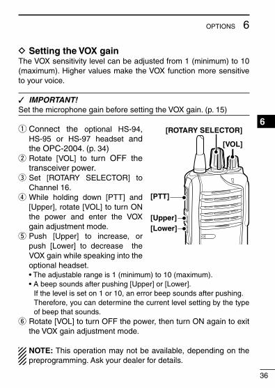
D Setting the VOX gainThe VOX sensitivity level can be adjusted from 1 (minimum) to 10 (maximum). Higher values make the VOX function more sensitive to your voice.
IMPORTANT! ✓
Set the microphone gain before setting the VOX gain. (p. 15)
Connect the q optional HS-94, HS-95 or HS-97 headset and the OPC-2004. (p. 34) Rotate [VOL] to t w urn OFF the transceiver power. Set [ROTARY SELECTOR] to e
Channel 16. While holding down [PTT] and r
[Upper], rotate [VOL] to turn ON the power and enter the VOX gain adjustment mode. Push [Upper] to increase, or t
push [Lower] to decrease the VOX gain while speaking into the optional headset.
•Theadjustablerangeis1(minimum)to10(maximum). •Abeepsoundsafterpushing[Upper]or[Lower]. If the level is set on 1 or 10, an error beep sounds after pushing. Therefore, you can determine the current level setting by the type
of beep that sounds.y Rotate [VOL] to turn OFF the power, then turn ON again to exit
the VOX gain adjustment mode.
NOTE: This operation may not be available, depending on the preprogramming. Ask your dealer for details.
[VOL]
[Upper]
[ROTARY SELECTOR]
[PTT]
[Lower]
37
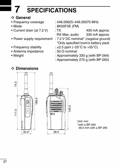
7 SPECIFICATIONSGeneral D
•Frequencycoverage :446.00625–446.09375MHz•Mode :8K50F3E(FM)•Currentdrain(at7.2V) :TX 400mAapprox.
RX Max. audio 330 mA approx.•Powersupplyrequirement :7.2VDCnominal*(negative ground)
*Only specified Icom’s battery pack•Frequencystability :±2.5ppm(–25°Cto+55°C)•Antennaimpedance :50˘ nominal•Weight :Approximately330g(withBP-264) :Approximately270g(withBP-265)
Dimensions D
58.0
135.
5
32.0*
111.
574
.5
Unit: mm
186.
0
*with a BP-26436.5 mm with a BP-265

38
7SPECIFICATIONS
1
2
3
4
5
6
7
8
9
10
11
12
13
14
15
16
17
18
19
20
Transmitter D•Outputpower :0.5WERP•Modulationsystem :Variablereactancefrequency
modulation•Max.frequencydeviation :±2.5kHz•Spuriousemissions :0.25µW(1GHzorbelow)
1.00µW(above1GHz)•Adjacentchannelpower :60dB•Externalmic.connector :3conductor2.5(d)mm/2.2k˘
Receiver D•Receivesystem :Doubleconversion
superheterodyne•Sensitivity(20dBSINAD) :–4dBµV(EMF)(typical)•Squelchsensitivity :26.5dBµV/m(Threshold)•Intermodulationrejectionratio :86.29dBµV/m•Spurious response rejection ratio:91.29dBµV/m•Adjacentchannelselectivity :81.29dBµV/m•Audiooutputpower :0.8W(typical)at5%distortion
with a 12 ˘ load 0.4W(typical)at5%distortion
with an 8 ˘ load•Externalspeakerconnector :2conductor3.5(d)mm/8˘
All stated specifications are subject to change without notice or obligation.

39
8 INDEXA
Auto scan function ............ 11, 17
BBattery Case .............................. 3, 30 Caution (Li-ion) .................. 21 Caution (Ni-MH) ................ 19 Chargers ............................ 24 Charging ............................ 19 Life ..................................... 31 Pack ..................................... 3 Type selection .................... 10Belt clip ..................................... 2
CChannel selection ................... 11Country code list ........................ iiCTCSS tone ........................... 12
DDefinitions ...................................iDTCS code ............................. 12
FFront panel................................ 5
JJack cover ............................. 4, 6
KKey functions ............................ 7 Lock key .............................. 8 Memory channel select keys . 7 Monitor key .......................... 8 Priority channel rewrite keys . 7 Priority channel select keys . 7 Scan keys ............................ 7 Siren key .............................. 8 Surveillance key .................. 8
LLED indicator ........................ 6, 9Lower key [Lower] ..................... 6
MMicrophone gain setting ......... 15
OOptions ................................... 31
PPenalty timer ........................... 14Power ON ............................... 10Power save function ................ 18Preprogrammed frequency and CTCSS tone list (Default) ....... 13Priority A channel selection .... 17PTT Switch [PTT] ..................... 6

40
8INDEX
1
2
3
4
5
6
7
8
9
10
11
12
13
14
15
16
17
18
19
20
RRapid charge Using the BC-191 to charge
the BP-264 ........................ 24 Using the BC-193 to charge
the BP-265 ........................ 26 Using the BC-197 to charge
the BP-264 or BP-265 ....... 27Receiving ................................ 12Regular charge Using the BC-192 to charge
the BP-264 ........................ 25Rotary selector ......................... 5
SSquelch level setting ............... 16Side panel ................................. 5Speaker-microphone jack [SP MIC] ................................... 6Specifications ......................... 37Supplied accessories................ 1
TTime-out timer ........................ 14Top panel .................................. 5Transmitting ............................ 12 Inhibit function ................... 14 Notes ................................. 14
UUpper key [Upper]..................... 6
VVolume control [VOL] ................ 5VOX function ........................... 34 Turning ON or OFF ............ 35 Unit connection .................. 34 VOX gain setting ................ 36
1-1-32 Kamiminami, Hirano-ku, Osaka 547-0003, Japan
< Intended Country of Use >ATFIITPLGBRO
BEFRLVPTISTR
CYDELTSKLIHR
CZGRLUSINO
DKHUMTESCH
EEIENLSEBG
A-6954D-1EUPrinted in Japan© 2011 Icom Inc.
Printed on recycled paper with soy ink.
#91 EUR-22, #92 EUR-23
< Intended Country of Use >ATFIITPLGBRO
BEFRLVPTISTR
CYDELTSKLIHR
CZGRLUSINO
DKHUMTESCH
EEIENLSEBG
#93 UK-02, #94 UK-03

ABOUT CE
DECLARATIONOF CONFORMITY
We Icom Inc. Japan1-1-32, Kamiminami, Hirano-kuOsaka 547-0003, Japan
Kind of equipment:
Type-designation:
Signature
Authorized representative name
Place and date of issue
Version (where applicable):Y. FurukawaGeneral Manager
Icom (Europe) GmbHCommunication EquipmentAuf der Krautweide 24,65812 Bad Soden am Taunus,Germany
PMR446 TRANSCEIVER
iC- f27sr
4th Jul. 2011Bad Soden
Declare on our sole responsibility that this equipment complies with the essential requirements of the Radio and Telecommunications Terminal Equipment Directive, 1999/5/EC, and that any applicable Essential Test Suite measurements have been performed.
This compliance is based on conformity with the following harmonised standards, specifications or documents:
EN 60950-1:2006/A1:2010EN 300 296-2 V1.3.1 (2010-07)EN 301 489-1 V1.8.1 (2008-04)EN 301 489-5 V1.3.1 (2002-08)
i)ii)iii) iv)v) vi)
JUN.2011
The IC-F27SR complies with the essential require-ments of the European Radio and Telecommuni-cation Terminal Directive 1999/5/EC.
A-6954D-2EU
Related Documents