PMO–FLOOD CONTROL and SABO ENGINEERING CENTER Department of Public Works and Highways FCSEC TECHNICAL REPORT Experiment on the Effective Arrangement of Spur Dikes as Countermeasure Against Bank Erosion in Agos River and St. Bernard, Southern Leyte Landslide Field Report Volume 2 (2 nd Edition) 2007.1 JAPAN INTERNATIONAL COOPERATION AGENCY

Welcome message from author
This document is posted to help you gain knowledge. Please leave a comment to let me know what you think about it! Share it to your friends and learn new things together.
Transcript

PMO–FLOOD CONTROL and SABO ENGINEERING CENTER Department of Public Works and Highways
FCSEC TECHNICAL REPORT
Experiment on the Effective Arrangement of Spur
Dikes as Countermeasure Against Bank Erosion in Agos River
and
St. Bernard, Southern Leyte Landslide Field Report
Volume 2 (2nd Edition) 2007.1
JAPAN INTERNATIONAL COOPERATION AGENCY

MESSAGE The Philippine environmental setting is prone to geological and hydro-meteorological
hazards. Recent disaster in the province of Quezon, Aurora and Southern Leyte
were triggered by extreme weather conditions on geologically weak localities.
Part of the response of the Flood Control and Sabo Engineering Center (FCSEC) is
to investigate the disaster sites to recommend, plan, and design appropriate
countermeasure. The reports on this volume include the “Experiment on the Effective
Arrangement of Spur Dikes as Countermeasure Against Bank Erosion in Agos River”
and “The St. Bernard, Southern Leyte Landslide Field Report” as our contribution to
disaster mitigations.
Together with the JICA experts, the staff of FCSEC investigated the site in
Guinsaguon, St. Bernard Southern Leyte and planned the appropriate
countermeasures for Agos River through hydraulic model experiment to come up
with these reports.
It is our hopes that these undertakings will help the engineers expose them to
landslide mechanism and will further their understanding in planning and design of
flood and erosion mitigation countermeasures.
RESITO V. DAVID, MNSA
Project Director

Table of Contents
Message
Experiment on the Effective Arrangement of Spur Dikes as Countermeasure Against Bank Erosion in Agos River
Abstract
Introduction Background Information Objectives of the Experiment Underlying Principles Spur Dikes Principles Methodology Experiment Conditions Experiment Results and Analysis Conclusion Recommendation Acknowledgement
St. Bernard, Southern Leyte Field Report
Background
Physiography and Geology Climate Landslide Observation Analysis Recommendation Acknowledgement

Abstract:Prolonged extreme rainfall events have often devastating effect especiallyin a meandering channel eroding and destroying banks and riverstructures, lives, livelihood and investments. Structural approach is oneof the measures to reduce vulnerability to disaster. As a way of probingthe appropriateness of chosen structures, scaled down modeling of spurdikes and cut off channel in an erodible bank were simulated in thehydraulic laboratory. Through satellite images and GIS software, theinsufficient data required in making river model were supplementd. Thealignment and width of the target river segment were laid out on theflume and overlaid with sediment samples which would have the samehydraulic effect with the actual river. The bedform of the actual targetriver segment was replicated on the flume after introducing waterdischarge. The impermeable spur dikes with foot protection proved tohave the best results. Arranging the spur dikes according to the flowlines of the river, thus necessitating variations in the length of spur dikesand orientation, has controlled the scouring and deposition of thesediments and deflected the flow away from the bank.
Key Words : Spurdikes, length, alignment, flow line, scour
IntroductionFour successive storms on November 2004 hit the towns of Real, Infanta, General Nakarin Quezon and Dinggalan in Aurora Province. Rainfall intensity on November 29, 2004 inInfanta, Quezon reached 342 mm for nine hours per PAGASA record. Consequent dis-charge of 6 meter in the Agos River damaged the bridge and breached the 300 m rightbank retaining wall downstream, which aggravated the inundation in the town proper. Theoverwhelming damages require concerted efforts to rehabilitate and to prevent future ca-tastrophe.
With the request of technical assistance of the municipality of Infanta, Quezon, the PMO-Flood Control and Sabo Engineering Center (PMO-FCSEC), Department of Public Worksand Highways provided experimental river modeling. Although not the ultimate solution,the perceived feasible urgent countermeasures on the eroding bank were spur dikes toinduce deposition and push the main flow away from the bank. The experiment focused onthis type of structure which was carried out from November to December 2005.
Experiment on the Effective Arrangement ofExperiment on the Effective Arrangement ofExperiment on the Effective Arrangement ofExperiment on the Effective Arrangement ofExperiment on the Effective Arrangement ofSpur Dikes as Countermeasures AgainstSpur Dikes as Countermeasures AgainstSpur Dikes as Countermeasures AgainstSpur Dikes as Countermeasures AgainstSpur Dikes as Countermeasures Against
Bank Erosion in Agos RiverBank Erosion in Agos RiverBank Erosion in Agos RiverBank Erosion in Agos RiverBank Erosion in Agos River
1
Background InformationInfanta lies on the alluvial plain highly vulnerable to flood and sediment disaster. It wasformed over many years by the discharges emanating from the mountain ranges of theSierra Madre to Agos river and by the sediment depositions on the alluvial fan.
Agos River has drainage area of approximately 1,000 km2.The banks are highly suscep-tible to erosion due to the high energy gradient during flood time affecting the adjacentcommunity. From the Sierra Madre mountain range, it flows out to the Pacific Ocean. It isprone to frequent changeable river course due to heavy sedimentation and sharp changesin slope as manifested by the existence of the old in the present river course. The currentcourse is temporal subject to alteraton if significant flood occurs due to sediment loadtransport. The river course meanders to the southeast downstream from the Agos Bridge,whcih connects Infanta and Gen Nakar . Farther downstream, sandbar develops on theleft bank while erosion occurs at the right bank.
The 2004 rainfall events caused many slope movements in the Sierra Madre mountains inQuezon and Aurora. Gullies were filled with sediments causing barriers and natural damsfor water flow. Their collapses and outbursts brought devastating sediments, logs anduprooted trees down from the hills. The hill slopes still have unaccounted volume ofunstable sediments at present.
At the height of the storm, the high water stage and velocity breached the river wall anddirected part of river flow to the town proper, which exacerbated the flood situation. Thereis an urgent need to counter the effect of the river flow. Spur dike, revetment or combina-tion of both and sabo projects are essential to reduce the damage wrought by the uncon-trolled hydraulic river conditions. Initially, experiment was conceived to determine the hy-draulic conditions in the scaled down model of spur dikes and re-channeling as counter-measures.
Objectives of the experimentThe objective of the experiment is to determine the effective arrangement of spur dikesand the effect of re-channeling to prevent bank erosion by controlling flow pattern in ameandering river channel using movable bed experi-ment and to prepare implementing method despite limi-tations on the river information.
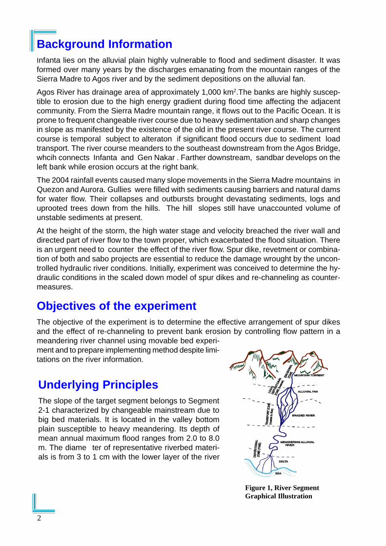
Underlying PrinciplesThe slope of the target segment belongs to Segment2-1 characterized by changeable mainstream due tobig bed materials. It is located in the valley bottomplain susceptible to heavy meandering. Its depth ofmean annual maximum flood ranges from 2.0 to 8.0m. The diame ter of representative riverbed materi-als is from 3 to 1 cm with the lower layer of the river
Figure 1, River Segment Graphical Illustration
2

Spur Dike PrinciplesSpur dikes are indirect structures laid on the river channel oriented perpendicularly orinclined upward or downward from the bank to dissipate the velocity, deflect the directionand induce depositions in between structures.
There are two types of spur dikes, the permeable and the impermeable types. The formerallow passage of flow while the latter are rigid. Orientation of the spur dikes varies depend-ing on the flow direction of the river; more often they are perpendicular to the bank.
MethodologyPlanning of proper countermeasures requires sufficient information. NAMRIA 1:50,000map, site photos, river channel gradient equivalent to 1/600, sediment size ranging from 1mm to 15 mm sand and gravel, flood level and unosat satellite images were the informa-tion on hand. The depth of the water was reckoned from the past maximum flood. Value ofmanning’s n is equivalent to 0.035, river width of 200 m and the depth of the river atbankful capacity is approximately 3 m. The estimated velocity was 2.4 m/s while the dis-charge was 1,500m3/s.
Estimation of plan shape of the river
UNOSAT images from http://www.unosat.com where the picture of the alignment and ex-tent of the river system were extracted compensated the deficiency of detailed informationof the river. Images were geo-referenced and viewed by Manifold and Map Info GIS soft-ware to get the river extent. Its resolution is sufficient enough to delineate the river banklines. From the GIS, the x-y coordinates of the bank lines were calculated and exported toMS Excel and laid out on the flume according to the planned scale.
Proposed Countermeasures
The Type II Boulder Spurdikes, the permeable spur dikes using pile model, and the cutoff channel on the deposited inner bend of the target area were proposed.
The typical specifications of Type II Boulder spur dikes are as follows :o Dimensions: Length =20m (10% of average width of the river), Crest=2m,
Height=1m (33%of flood level)o Spacing: Spacing=30m (1.5 x Length)
Conditions are derived from the Technical Standards and Guidelines for Flood Control,under Project ENCA.
Figure 2, Boulder “Type II”Source: Typical Standard Drawing, Project ENCA
3

Laboratory Model
The lahar flume consists of two flumes; the 1 m x 10 m and the 4 m x 10 m correspondingto the upper and lower sections, respectively, Figure 6. The flume size constrained thescale to 1/350 and 1/200 for horizontal and vertical, respectively.
The galvanized sheet plates 20 cm fixed to the 10 x 10 cm timber studs confined theshape and alignment of the river model as laid out on the flume. The lahar sample fromPasig Potrero River, Pampanga served as materials for the scaled down model which hasmean diameter of 0.45 mm with specific gravity of 2.5. The channel was uniformly filledwith 10 cm lahar.
The spur dike models of impermeable type were made of concrete blocks molded withdifferent length for flexibility in varied cases. On the other hand, the permeable type modelconsists of 3mm diameter sticks, resembling piles, arranged in arrays of two to threedepending on the case and spaced at 2 – 3 mm from center to center of the sticks. Pleaserefer to Figure 8. The column was spaced at 5 cm. Embedment on the bed was two thirdsof the stick height with the exposed part as high as the exposed impermeable spur dike.
The third countermeasure was re-channeling at the bend to replicate the actual works onsite.
Figure 3, Spur dike Model
Figure 4, Agos River UNOSAT Image Figure 5, Channel Model Coordinatesfrom Excel
4
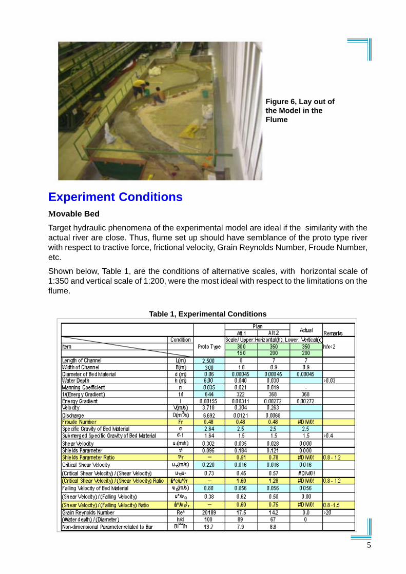
Figure 6, Lay out ofthe Model in theFlume
Experiment ConditionsMovable BedTarget hydraulic phenomena of the experimental model are ideal if the similarity with theactual river are close. Thus, flume set up should have semblance of the proto type riverwith respect to tractive force, frictional velocity, Grain Reynolds Number, Froude Number,etc.
Shown below, Table 1, are the conditions of alternative scales, with horizontal scale of1:350 and vertical scale of 1:200, were the most ideal with respect to the limitations on theflume.
Table 1, Experimental Conditions
5

Stationing
The target area for measurement was within the station limit from 6 +500 to 1+000, start-ing from the lower tip of the flume with one meter interval along the center alignment of thechannel. Critical points were from stations 2+500 to 4+ 000. Please refer to Figure 10.
Case DescriptionCase 1, Preliminary Run
The preliminary case was designed to verify if the model could reproduce the scouring anderosion pattern, which occurred in a proto type river; and to observe the flow condition,which would serve as the basis for the necessary countermeasures to be introduced in theflume.
To form the likness of prototype river bed, discharge was first introduced at maximum of408 lit/min and reduced to 204 -210 liter/min after an hour. The discharges were equiva-lent to 6 m, the flood discharge at the height of the typhoon, November 29, 2004 and 3 m,representing the ordinary flood discharge in the actual river.
Case 2, Arrangement of Spur dikes Per Standard
Case 2 was based from the perceived best set up of spur dikes in the target bend alongthe breached retaining wall with maximum standard length of 10% of the river width. Themaximum length measured 10 cm, spaced at twice the length (S=2L). From sta 1+000 tosta 4+500, the number of spur dikes installed were 17 pieces,
Case 3
The number of spur dikes was reduced at the upstream portion, taking out the shorterones, which were observed previously to divert the flow and induced sediment depositionnegligibly. The spur dike length gradually increased starting from sta 4+000 to downstreamof sta 2+000, according to the assumed flow line placing the longer one on the severelyscoured sections. Spacing was at twice the length. 11 pieces of spur dikes were laid outfrom sta 1+200 to 3+800.
Discharge was at 204 lit/min for 60 minutes duration.
Figure 7, Location and Arrangement of Spur DikesCase 4
The arrangement and conditions were the same as case 3 except that the base of thespurdikes was fortified with garvel on the severely scoured sections, from S5 to S9.
6

Table 2 Spur dike Location forCase 3 – Case 6
Case 5
Impermeable type spur dikes in lines of pilemodels, measuring 2 mm in diameter, werearranged on the same spots as the previouscase. One spur dike comprised two lines wherespacing between each pile were 3 mm per rowand 6 mm per column. Spacing between spurdikes were at twice the length where the maxi-mum length was 20 cm. (L=0.2 of river width).
The discharge was 204 lit/min at 45 minutes.
Case 6
The arrangement of spur dikes for Case 6 wasthe same as that of case 5. Spur dikes S6 and S7 have three lines with the same spacingbetween each pile. The bases of the spur dikes on deeply scoured sections were providedwith gravel as protection.
Figure 8, Permeable Type SpurDike Model
Figure 9, Cut-OffChannel Model
Spur Dike Length (cm) LocationS-1 5 3+830S-2 6.25 3+730S-3 7.5 3+600S-4 11.25 3+400S-5 15 3+200S-6 20 2+800S-7 20 2+400S-8 20 2+000S-9 15 1+700S-10 10 1+500S-11 6.25 1+350
Case 7
Cut off channel on the meandering segmentof the river was excavated to divert the flowaway from the scoured bank. The width of thecut-off was 10 cm. Case 7 was intended toshow the effect of cut off channel in the ac-tual river currently being undertaken.
Cut offChannel
7
6 mm
2-3 mm2-3 mm dia pile model
Length var.
2 Columns for Case 5
3 Columns for Case 6 for S6 & S7
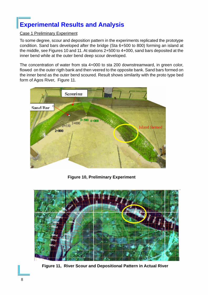
Experimental Results and AnalysisCase 1 Preliminary Experiment
To some degree, scour and deposition pattern in the experiments replicated the prototypecondition. Sand bars developed after the bridge (Sta 6+500 to 800) forming an island atthe middle, see Figures 10 and 11. At stations 2+500 to 4+000, sand bars deposited at theinner bend while at the outer bend deep scour developed.
The concentration of water from sta 4+000 to sta 200 downstreamward, in green color,flowed on the outer rigth bank and then veered to the opposite bank. Sand bars formed onthe inner bend as the outer bend scoured. Result shows similarity with the proto type bedform of Agos River, Figure 11.
Figure 11, River Scour and Depositional Pattern in Actual River
Figure 10, Preliminary Experiment
Island formed
8

Case 2
Six spur dikes downstream of 2+500 were disarrayed and knocked off due to deep scouralong the right bank after 30 minutes of discharge.
In between stations 1+500 to 2+500 was the converging point of deflected water flow byspur dikes and the main flow from the upstream. This flow incised deep scour on the bedalong its longitudinal path. The six spur dikes on this section were not able to minimizebank erosion.
On the other hand, the 5 spur dikes from Sta. 3+700 to 3+000 induced sediment deposi-tion in between them. Those upstream of sta. 4+000 were not on the high velocity flow;thus, sediment depositions were induced.
Comparing the result with case 1, the scoured portion was transferred farther downstreamand the bank erosion prevention was minimal.
Figure 12, Spur DikeArrangement Per
Standard
Figure 13, Condition of Spur Dikeat Sta. 2+500
Figure 14, Depositionand Scouring PatternAround Spur Dikes,
Case 2
9

Case 3
Two minutes after the discharge, the tip end materials of spur dikes S7 and S8 began toscour. Seven minutes later, S7 was disarrayed, while S6 deflected the flow away from thebank.
With progressive tip end scouring of spur dikes, S7 to S9 tilted to upstream orientation.Heavy scour around all theses spur dikes disarrayed S7, which was the most severelydeformed. Figure 15 shows concentration of flow at S8, while the section was constricteddue to the deposition of sediments on the opposite bend.
The blocks of S8 skewed upstream wise as the front bed materials around the spur dikescoured. For S9, only the tip end block fell and leaned facing the stream, where the deep-est scour was 7 cm. For S8, the widest scour was 7 to 8 cm on both upstream and down-stream sides of spur dikes. At S9, the scoured depth was approximately 5 cm.
Scour at the ends of S2 to S5 were within the range of 3 to 4 cm while S6 and S10 have 5to 6 cm. S11 remained almost unchanged.
From S7 to S9, there was heavy scour around spur dikes; however, compared to case 2,this was relatively smaller. Near the boundaries of spur dikes, heavy scour was observedbut longitudinal bed incission due to series of spur dikes was reduced significantly.
Relatively, the scour was transferred from the riverbank farther over the tip of the spurdikes, Figure 16(b); thereby, reducing the degree of erosion along the riverbank.
Although, S8 was disarrayed and toppled, sediments were still deposited on the upstreamof spur dike. This suggests that spur dikes have significant beneficial effects to preventriverbank erosion.
Figure 15, Overview of Flow Pattern of
Figure 16 (a)
Figure 16 (b)
Scour and Deposition Pattern for Case 3
10

Figure 17(a)
Effect on S7 to S9 Case 3Figure 17(b)
Case 4
Figure 18, Flow Pattern, Case 4
As mentioned earlier, spur dikeswere protected by gravel at the footor base. The protection gave betterfunctional results and stability of thespur dikes.
S8 was effective to deflect the wateraway from the bank; however, with-out added protection it was easilytoppled.
The effect of spur dike deviated thewater effectively especially from S6to S8. Pleas refer to the green coloron the opposite figures showingconsiderable distance from the riverbank of the main flow.
Figure 19, Effect on S8, Case 4 Figure 20, Flow Direction andDepositional Pattern at S6 andS8
11

Figure 21, Effect on S7 and S8, SpurDike with Foot Protection
Comparing the without and with coun-termeasures, specifically cases 2 and 3,the scour changed drastically as the spurdikes were installed. The scour aroundspur dikes and near riverbank was miti-gated as the foot and the base were pro-tected. Generally, the flow deflected nearthe ends of spur dikes causing longitu-dinally incission along the river channelforming thalweg, the deepest portion ofthe river bed. This case was the mosteffective among all the cases in this ex-periment. S8 captured sedimenteffectively.Also in case 2, where therewas no foot protection, the upstream anddownstream of spur dikes scoured. This isnot evident in case 3, where there were footor base protections.
Case 5
The lines of piles served as permeable spur dike which allowed the water to passthrough in between spaces which dissipated the velocity, diverted the flow, reducedscouring and induced deposition.
Among all the permeable spur dikes set up for this case, S6 was located on the highvelocity flow zone blocking the main stream from upstream; thus, exposed to heavyscour. Spur dikes upstream of S6 resisted the flow towards their tip ends. The conver-gence of flow moved to S6; hence, subjected to high velocity after 2 minutes of dis-charge. This made S6 destabilized more easily as compared to other spur dikes.
Comparatively based on this case, the rigid spur dikes performed better than the perme-able pile type.
Referring to Figure 22, in between S7 and S8, bed scour was caused by gradual removalof pile model at S7as carried by the current. Water passed through the bigger spaces andcarried the bed particles.
As discussed earlier, the mainstream was towards to S6, hit S7, then bounced from thebank and diverted to the center by S8. Although directly hit, S6 was not as severe as S7due to the following reasons:
The piles of S6 where the main flow hit directly were swayed down away becauseof scouring, allowing the discharge to pass through with less interruption.The main course flowed from S6 to S7 to the riverbank and carried away somepiles; then, the flow moved to the riverbank side of S7.The riverbed scoured along riverbank just downstream of S7.The deep scoured portion extended longitudinally and was formed between S6
12
Under normal condition, deep scours occur at the tip of spur dikes forming longitudinalscour at the ends of series of spur dikes as the flow is deflected from the river bank. Theprotection at the tip end may be another subject of interest for the next research to havemore ostensible effect of spur dikes.
This case shows the significance of foot protection around spur dike to reinforce, stabilizeand enhance its effect.

· and S8 along riverbank side.
Given the above conditions, S8 deflected the waterflow and induced sediment deposition effectively.However, the outermost piles from the bank of S8were carried away by the flow as the bed scouredgradually until it could no longer reduce the velocityand deflect the flow. Hence ,the run was terminatedafter 45 min.
Considering this result, the impermeable and morerigid spur dikes are ideal to ensure that the flow canbe diverted in a meandering and high velocity sec-tions of the channel, such as in the location of S6.
Permeable pile spur dikes when partially damagedcan lead to the damaged of the succeeding spur dikesdownstream, in some cases more serious.
Figure 22, Effect on S6 andS7, Permeable Type Spur
dike
Case 6
Similar to Case 5, after the the main flow passed di-rectly by S6, the velocity was slightly reduced down-stream. Then when the flow reached S7, the flow deflected away from the bank. Pleaserefer to Figure 22.
Longitudinal scouring along the channel was over the tip of S6 to S8, which have sameresult as that of case 4.
The depth of scour near the bank at spur dikes S6 to S7, S7 to S8 and S5 to S6 were-1 cm , 5 cm , and 1 cm, respectively.
The pile spur dikes protected by foot protection exhibited similar efficiency as case 4.Although in between each spur dikes and riverbank, especially in the most affected area,scour could not be eliminated.
The fortified permeable pile type spur dikes kept the scouring away form the riverbank,which eventually prevent erosion.
Figure 23, Depositional
Pattern at S6 and S7
Figure 24,Flow Direction
and DepositionalPattern
From S1 to S5
13

Case 7
Ten minutes after the discharge, the opening or the intake of the cut off channel started toerode especially on the right side while the sediment deposited on the immediate down-stream bed. Please refer to Figure 25, sluggish movement of the sediment came withmarginal inflow (A direction), to the channel while the main flow (B direction), veered to-ward the outer bank. Progressive erosion took place as discharge continued until theoriginal cut off channel was filled with sediment deposits. The bed accretion reduced theinflow and its discharge capacity. After the run, the deposition was measured at 1 cm,Figure 26.
With this condition, bank erosion at the target section at the main river course could not beprevented, since volume of discharge at the cut-off channel was negligible.
The run lasted only for 40 minutes since the cut off channel became ineffective as deposi-tion have accumulated on the bed.
Figure 25, Flow Distributionat the Junction of Cut-off
ChannelFigure 26, Depth ofScour
Water Velocity and Bed Elevation
Water velocities at different points were measured during high water stage at the stationsshown on the graphs. Velocity measurement was up to case 4 only, presuming similaritywith succeeding cases, since the position of the spur dikes was on the same location fromcase 4 to case 6. Correspondingly, the bed elevations were obtained on the same spotsafter draining the water from the bed for every runs in each case.
Near the vicinity of stations 2 +700 and 2 + 200, severe scouring was expected to occursince this was the attacked zone and at the high velocity flow zone. Comparatively shownonthe next page are the results of all the cases.
From the velocity distribution at station 2+500, Figure 27, case 4 dissipated velocity sig-nificantly and diverted the flow farthest from the bank. Although, cases 2 and 3 reducedthe velocity at the bank most part, the control of scour was not as great as that of case 4.
The lowest bed elevation at case 4 tended to move to the center, while in cases 2 and 3 itwas near the bank, and in case 1 without countermeasure, it was at the rightmost.
14

Case 5 has somewhat big scour near the bank since most pile members of the spurdike models were carried by the water flow. Case 6, permeable type spur dikes with footprotection starting from 2+500, has good results comparably at par with case 4.
Figure 33, Velocity at Sta 4+000 Figure 34, Bed Elevation at Sta 4+000
Figure 31, Velocity at Sta. 3+500 Figure 32, Bed Elevation at Station 3+500
Figure 29, Velocity at 3+000 Figure 31, Bed Elevation at 3+000
Figure 27, Velocity at 2+500 Figure 28, Bed Elevation at 2+500
15

Case 7 did not exhibit mitigating effect, on the other hand, deposition was seen on the cutoff section. Prolonged discharge and accumulated depositions will cause the cut-off chan-nel ineffective.
For Cases 4 and 6, Figure 29, sta 3+000 had no foot protections. Case1 exhibited highvelocity at the right bank. Cases 2, 3 and 4 have low velocities at the far right. Farther 10cm from right bank, case2 and 4 have slight differences. Case 3 still has low velocity andalmost equal beyond 20 cm to 20 cm from the bank.
Referring to Figure 30, among all the cases, case 2 is the most effective at this section.Bed elevation was highest among all the cases.
Velocity distributions among the cases depicted in Figure 31 show similar trends exceptfor without countermeasures. Decreasing velocity could be observed towards the rightbank whereas in the without countermeasure velocity increased
The section shows, case 6 has the best result, where the bed profile gently descendedfrom right bank to 30 cm away; then, from thereon the bed rose gradually to the left bank.
Sta 4+000 was located at the beginning of the series of spur dikes. It can be noted fromfigure 33, that the velocity of case 1, no countermeasures case, is highest while its bedelevation is lowest at 20 cm from the right bank. The velocity from case 2 to case 4 showsimilar pattern, which gradually increase from 20 cm to 50 cm from the right bank.
The bed elevation in case 7 did not change significantly from the original setup due to theshorter duration of run compared with other cases, especially on the right bank. Corre-spondingly, it can be seen the elevation of the bed is high on this portion.
When water velocity is high, scouring is expected to be great. The progress of the mitigat-ing effect of the spur dikes can be ascribed to the decrease in the water velocity and thescouring as modification of the countermeasures are applied after determining the resultsof each case.
The graph shows that velocity is higher in the case where there is no countermeasure,becomes moderate with insufficient countermeasures and reduces greatly with sufficientspur dikes with foot protection and with arrangement following the flow line. Conversely,the bed elevation shows the effect of the hydraulic conditions where the degree of scour-ing is directly proportional to the velocity.
Near the boundaries and in between spur dikes, velocity dissipated greatly as comparedto the flow near the center. High velocity is concentrated away from the bank starting fromthe tip end towards the center of the channel. In effect, the reduced velocity has lowertractive force to transport sediment downstream which in turn kept the bank protected.
ConclusionThe results of the experiment can draw some important conclusions in the planning anddesign of spur dikes.
The proposed channel excavation along the bend of the Agos River to divert and straightenthe flow from the critical bank have a positive effect for a moment but overtime its effeciencywill be reduced due to the sediment flows from the upstream per experiment result. Inactual river, the excavated channel will be filled by sediments soon since the channel iswithin the depositional zone of the meandering segment. Regular maintenance is neces-sary to sustain the flow capacity.
16

On the other hand, spur dikes have longer effective use. Maintenance is optional andcheaper. Improvement is flexible to suit the hydraulic characteristics of the channel. Be-fore making plans and design of the spur dike, the river hydraulics should be understoodby predicting and observing the flow pattern on the case to case basis. The variations inthe length, spacing and alignment of spur dikes should follow the flow line.
To have more effective result, determination of the most affected or directly hit portion bythe water flow is necessary. Length should be sufficient to deflect the flow effectively. Inactual river the length is proposed to be 50 to 70 m or 20 % of the river width. The lengthfollows the flow line to avoid abrupt deflection and damage the spur dikes. The arrange-ment of spur dikes is from smaller in the beginning and gradually elongated following theflow pattern, then decreases slowly up to the end of the series. Its objective is to keep theflow away while maintaining the stability of the spur dikes.
The spacing is less than or equal to twice the length of the spur dike in placed or theadjacent one. Shortening the space lesser than the required (lesser than twice the length)may be considered if scouring is still inevitable.
The impermeable or rigid spur dikes are necessary in the most severe portion of the riversegment.
Type II spur dike, most commonly used in the Philippines, is recommended for Agos River.The permeable and impermeable types can be combined to get more economical results,with the latter at the severest scoured portion. In case of boulder or rock foundation, piletype can not be applied.
Further, foot protection around and on the tip of spur dikes is indispensable for its stabilityto ensure its effect.
RecommendationSpur dikes are constructed phase by phase according to plan in a river segment in a fiscalbasis governed by the following.o Construction of spur dikes can be started from the upstream in the section where
scouring is not most severe. This will ensure that during heavy floods, the spur dike willsustain and not be washed away by the high velocity. Then, gradually, the spur dikeconstruction progresses from the low to high severe scoured zones.
o In the high priority area prone to heavy scouring and erosion, the spur dikes may beconstructed initially shorter than proposed and then gradually lengthen according toplan in the succeeding budget years to provide emergency or immediate protection.
If revetment is used as countermeasure, it needs enough depth of foundation, at least, 1mdeeper than deepest riverbed. The combination of shorter spur dike and revetment maybe functionally and cost effective and recommended to be tested in the actual field.
AcknowledgementThe experiment was undertaken under the Project ENCA on October 21 to December 03,2005 at the DPWH Hydraulic Laboratory Building. We appreciate the moral support of Mr.Resito V. David, PMO-FCSEC Director, Ms. Dolores M. Hipolito, Project Manager II andMr.Tokunaga, JICA Chief Advisor.Deep appreciation is extended to the officials of Infanta, Quezon for their full support; HonFilipina Amerika, the mayor; Mr. Eduardo Espiritu, municipal engineer and other officialsinvolved in the Agos River.
17

Mr. Alfredo M. Peñamante, OIC District Engineer of 1st Quezon, and his office providedassistance with the logistics.
ReferencesDepartment of Public Works and Highways and Japan International Cooperation
Agency, Volume 1, Flood Control, Technical Standards and Guidelines, Project forthe Enhancement of Capabilities in Flood Control and Sabo Engineering of theDPWH, March 2002
Department of Public Works and Highways and Japan International CooperationAgency, Typical Standard Drawings, Flood Control Structures, Project for theEnhancement of Capabilities in Flood Control and Sabo Engineering of theDPWH, March 2003
AuthorsJesse C. Felizardo, Engineer IV, PMO-Flood Control and Sabo Engineering Center,DPWH
Harold Uyap, Engineer III, PMO-Flood Control and Sabo Engineering Center, DPWH
Wataru Sakurai, JICA Sabo Expert, Project ENCA, DPWH
18
St. Bernard Landslide, Southern Leyte, Field Report Jesse C. Felizardo, Engineer, FCSEC, DPWH, Philippines
Yoshio Tokunaga, JICA Chief Adviser Watatu Sakurai, JICA Sabo Expert
1. Background
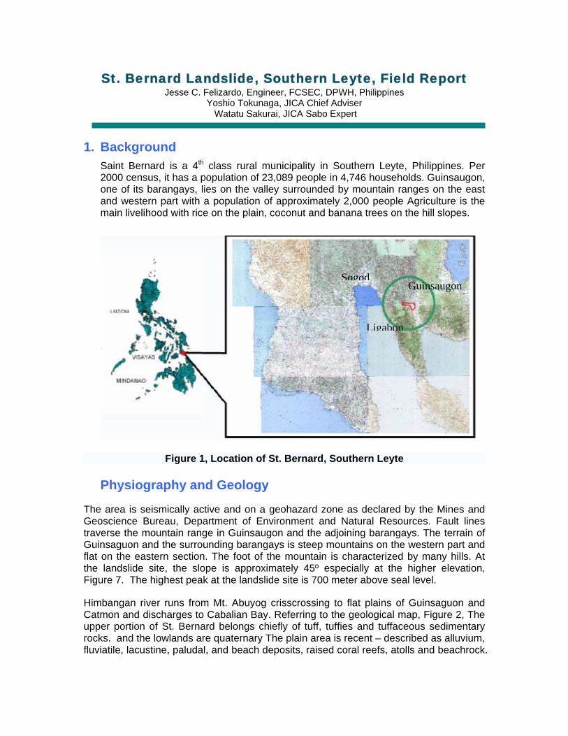
Saint Bernard is a 4 class rural municipality in Southern Leyte, Philippines. Per 2000 census, it has a population of 23,089 people in 4,746 households
th
. Guinsaugon, one of its barangays, lies on the valley surrounded by mountain ranges on the east and western part with a population of approximately 2,000 people Agriculture is the main livelihood with rice on the plain, coconut and banana trees on the hill slopes.
Guinsaugon
n
Figure 1, Location of St. Bernard, Southe
Physiography and Geology
The area is seismically active and on a geohazard zone as Geoscience Bureau, Department of Environment and Natutraverse the mountain range in Guinsaugon and the adjoiningGuinsaguon and the surrounding barangays is steep mountaiflat on the eastern section. The foot of the mountain is charthe landslide site, the slope is approximately 45º especialFigure 7. The highest peak at the landslide site is 700 meter a
Himbangan river runs from Mt. Abuyog crisscrossing to flat Catmon and discharges to Cabalian Bay. Referring to the geoupper portion of St. Bernard belongs chiefly of tuff, tuffies arocks. and the lowlands are quaternary The plain area is recefluviatile, lacustine, paludal, and beach deposits, raised coral
Ligabo
Sogod
rn Leyte
declared by the Mines and ral Resources. Fault lines barangays. The terrain of
ns on the western part and acterized by many hills. At ly at the higher elevation, bove seal level.
plains of Guinsaguon and logical map, Figure 2, The
nd tuffaceous sedimentary nt – described as alluvium, reefs, atolls and beachrock.
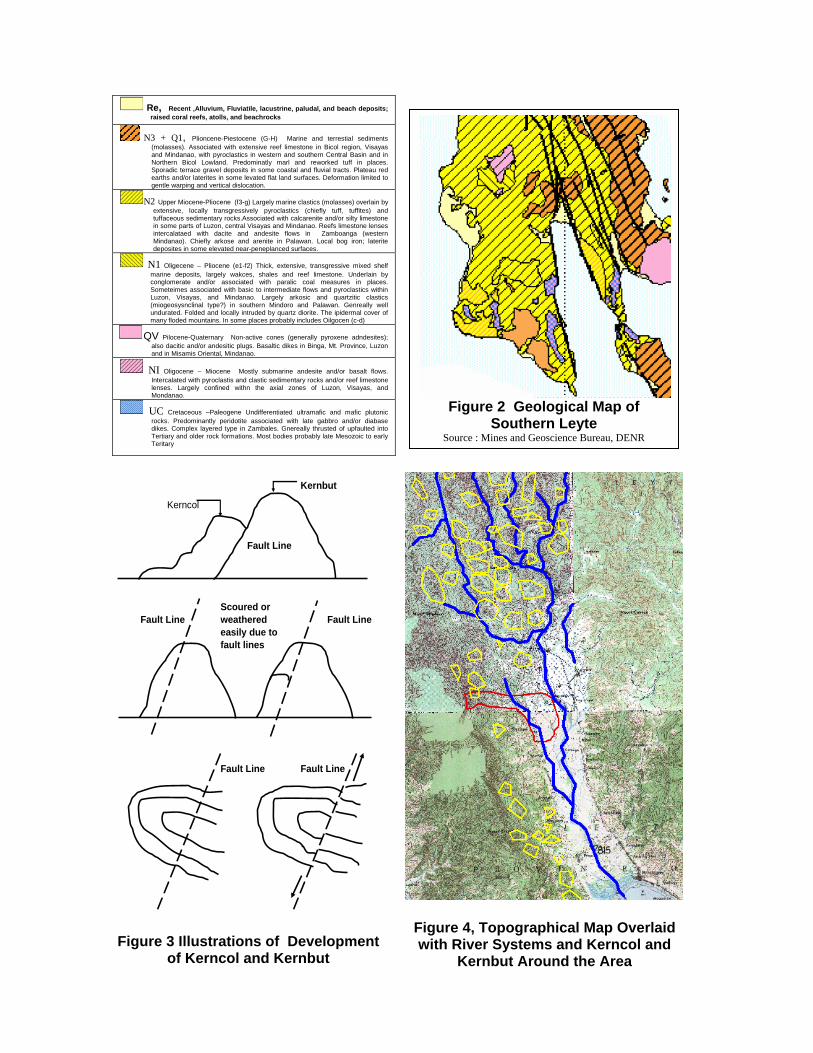
Re, Recent ,Alluvium, Fluviatile, lacustrine, paludal, and beach deposits; raised coral reefs, atolls, and beachrocks
N3 + Q1, Plioncene-Piestocene (G-H) Marine and terrestial sediments (molasses). Associated with extensive reef limestone in Bicol region, Visayas and Mindanao, with pyroclastics in western and southern Central Basin and in Northern Bicol Lowland. Predominatly marl and reworked tuff in places. Sporadic terrace gravel deposits in some coastal and fluvial tracts. Plateau red earths and/or laterites in some levated flat land surfaces. Deformation limited to gentle warping and vertical dislocation.
N2 Upper Miocene-Pliocene (f3-g) Largely marine clastics (molasses) overlain by extensive, locally transgressively pyroclastics (chiefly tuff, tuffites) and tuffaceous sedimentary rocks.Associated with calcarenite and/or silty limestone in some parts of Luzon, central Visayas and Mindanao. Reefs limestone lenses intercalataed with dacite and andesite flows in Zamboanga (western Mindanao). Chiefly arkose and arenite in Palawan. Local bog iron; laterite deposites in some elevated near-peneplanced surfaces.
N1 Oligecene – Pliocene (e1-f2) Thick, extensive, transgressive mixed shelf marine deposits, largely wakces, shales and reef limestone. Underlain by conglomerate and/or associated with paralic coal measures in places. Someteimes associated with basic to intermediate flows and pyroclastics within Luzon, Visayas, and Mindanao. Largely arkosic and quartzitic clastics (miogeosysnclinal type?) in southern Mindoro and Palawan. Genreally well undurated. Folded and locally intruded by quartz diorite. The ipidermal cover of many floded mountains. In some places probably includes Oilgocen (c-d)
QV Pilocene-Quaternary Non-active cones (generally pyroxene adndesites); also dacitic and/or andesitic plugs. Basaltic dikes in Binga, Mt. Province, Luzon and in Misamis Oriental, Mindanao.
NI Oligocene – Miocene Mostly submarine andesite and/or basalt flows. Intercalated with pyroclastis and clastic sedimentary rocks and/or reef limestone lenses. Largely confined withn the axial zones of Luzon, Visayas, and Mondanao.
UC Cretaceous –Paleogene Undifferentiated ultramafic and mafic plutonic rocks. Predominantly peridotite associated with late gabbro and/or diabase dikes. Complex layered type in Zambales. Gnereally thrusted of upfaulted into Tertiary and older rock formations. Most bodies probably late Mesozoic to early Teritary
Kernbut
Kerncol
Fault Line
Scoured or Fault Line weathered Fault Line
easily due to fault lines
Fault Line Fault Line
Figure 3 Illustrations of Development
of Kerncol and Kernbut
Figure 2 Geological Map of Southern Leyte
Source : Mines and Geoscience Bureau, DENR
Figure 4, Topographical Map Overlaid with River Systems and Kerncol and
Kernbut Around the Area
The major fault lines traverse the municipalities of Sogod, Libagon, St. Bernard and San Juan to Panaon Island. Fault lines run along the middle most stretch of the island of Leyte passing Guinsaguon at the lower tip. Please refer to Figure 4, the topographical map shows the river runs along the fault lines from north to south and the typical terrain has many kerncol and kernbut, enclosed with yellow polygons, which suggests that the area has been affected by existing active fault
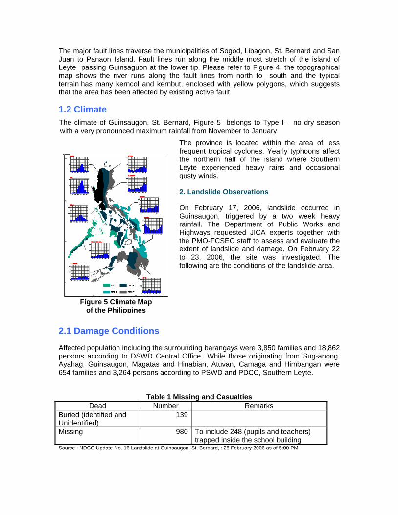
1.2 Climate The climate of Guinsaugon, St. Bernard, Figure 5 belongs to Type I – no dry season with a very pronounced maximum rainfall from November to January
The province is located within the area of less frequent tropical cyclones. Yearly typhoons affect the northern half of the island where Southern Leyte experienced heavy rains and occasional gusty winds.
Figure 5 Climate Map of the Philippines
2. Landslide Observations
On February 17, 2006, landslide occurred in Guinsaugon, triggered by a two week heavy rainfall. The Department of Public Works and Highways requested JICA experts together with the PMO-FCSEC staff to assess and evaluate the extent of landslide and damage. On February 22 to 23, 2006, the site was investigated. The following are the conditions of the landslide area.
2.1 Damage Conditions
Affected population including the surrounding barangays were 3,850 families and 18,862 persons according to DSWD Central Office While those originating from Sug-anong, Ayahag, Guinsaugon, Magatas and Hinabian, Atuvan, Camaga and Himbangan were 654 families and 3,264 persons according to PSWD and PDCC, Southern Leyte.
Table 1 Missing and Casualties
Dead Number Remarks Buried (identified and Unidentified)
139
Missing 980 To include 248 (pupils and teachers) trapped inside the school building
Source : NDCC Update No. 16 Landslide at Guinsaugon, St. Bernard, : 28 February 2006 as of 5:00 PM
2.2 Rainfall Condition
Libagon
55.2 56.8
157.2
131.0
171.0
30.6 23.410.0
32.4
2.6 9.4 4.00.0
20.0
40.060.080.0
100.0120.0140.0
160.0180.0
8 9 10 11 12 13 14 15 16 17 18 19 20
February 2006
Rain
fall
(mm
)
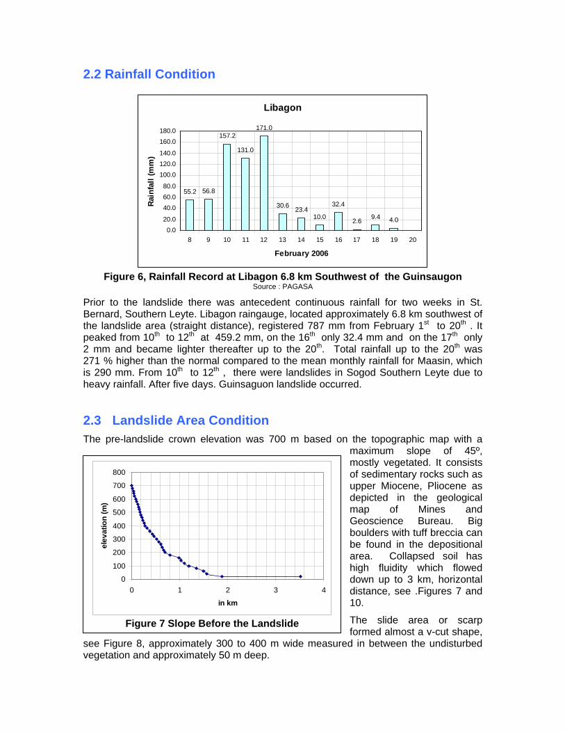
Figure 6, Rainfall Record at Libagon 6.8 km Southwest of the Guinsaugon
Source : PAGASA
Prior to the landslide there was antecedent continuous rainfall for two weeks in St. Bernard, Southern Leyte. Libagon raingauge, located approximately 6.8 km southwest of the landslide area (straight distance), registered 787 mm from February 1st to 20th . It peaked from 10th to 12th at 459.2 mm, on the 16th only 32.4 mm and on the 17th only 2 mm and became lighter thereafter up to the 20th. Total rainfall up to the 20th was 271 % higher than the normal compared to the mean monthly rainfall for Maasin, which is 290 mm. From 10th to 12th , there were landslides in Sogod Southern Leyte due to heavy rainfall. After five days. Guinsaguon landslide occurred.
2.3 Landslide Area Condition The pre-landslide crown elevation was 700 m based on the topographic map with a
maximum slope of 45º, mostly vegetated. It consists of sedimentary rocks such as upper Miocene, Pliocene as depicted in the geological map of Mines and Geoscience Bureau. Big boulders with tuff breccia can be found in the depositional area. Collapsed soil has high fluidity which flowed down up to 3 km, horizontal distance, see .Figures 7 and 10.
The slide area or scarp
sv
0
100
200
300
400
500
600
700
800
0 1 2 3
in km
elev
atio
n (m
)
4
Figure 7 Slope Before the Landslide
formed almost a v-cut shape,ee Figure 8, approximately 300 to 400 m wide measured in between the undisturbed egetation and approximately 50 m deep.
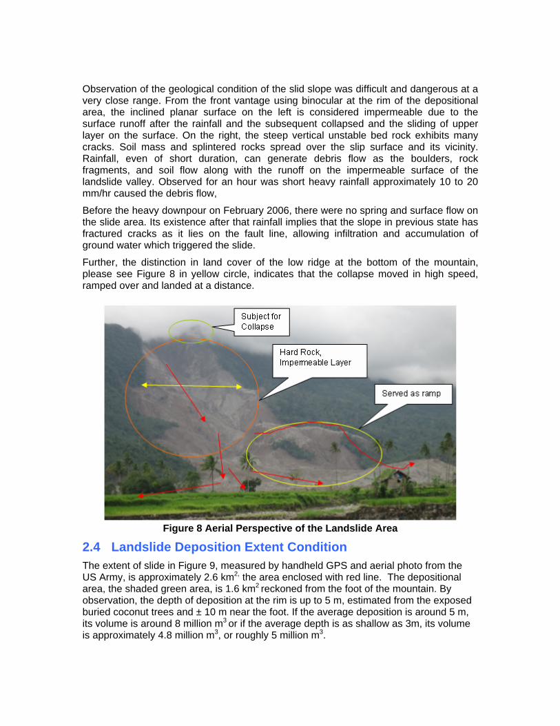
Observation of the geological condition of the slid slope was difficult and dangerous at a very close range. From the front vantage using binocular at the rim of the depositional area, the inclined planar surface on the left is considered impermeable due to the surface runoff after the rainfall and the subsequent collapsed and the sliding of upper layer on the surface. On the right, the steep vertical unstable bed rock exhibits many cracks. Soil mass and splintered rocks spread over the slip surface and its vicinity. Rainfall, even of short duration, can generate debris flow as the boulders, rock fragments, and soil flow along with the runoff on the impermeable surface of the landslide valley. Observed for an hour was short heavy rainfall approximately 10 to 20 mm/hr caused the debris flow,
Before the heavy downpour on February 2006, there were no spring and surface flow on the slide area. Its existence after that rainfall implies that the slope in previous state has fractured cracks as it lies on the fault line, allowing infiltration and accumulation of ground water which triggered the slide.
Further, the distinction in land cover of the low ridge at the bottom of the mountain, please see Figure 8 in yellow circle, indicates that the collapse moved in high speed, ramped over and landed at a distance.
Figure 8 Aerial Perspective of the Landslide Area
2.4 Landslide Deposition Extent Condition The extent of slide in Figure 9, measured by handheld GPS and aerial photo from the US Army, is approximately 2.6 km2, the area enclosed with red line. The depositional area, the shaded green area, is 1.6 km2 reckoned from the foot of the mountain. By observation, the depth of deposition at the rim is up to 5 m, estimated from the exposed buried coconut trees and ± 10 m near the foot. If the average deposition is around 5 m, its volume is around 8 million m3 or if the average depth is as shallow as 3m, its volume is approximately 4.8 million m3, or roughly 5 million m3.

Figure 9 Overview of Sediment Deposition
The typical condition of the deposits was that the collapsed soil flowed down for more than a kilometer. Beyond 2 km and farther from the foot of the mountain, the slope is almost flat exhibiting high water content and high fluidity, which makes it difficult to proceed from the rim to the mid-depositional area.
Deposits are composed of fine sediment, big boulders containing gravel and tuff breccia. Near the river, materials are fractured rocks which differ from other locations.
Debris Flow
Figure 10 Surface Flow
3.0 Analysis On the mechanism of landslide. The area is a steep terrain on an active fault line. The landslide is categorized as block glide or translational slide, which moved in relatively planar surface. It was geological in nature triggered by heavy rainfall, not illegal logging as some people believed.
Prolonged and heavy rainfall penetrated through many cracks and concentrated on the impermeable layer on the left upper slide area. The underground water weakened the strength of the fractured rock and the colluvial soil on the impermeable layer due to water pressure until the mass collapsed.
Engr Jun Sacro, of DPWH Southern Leyte District Engineering Office, mentioned of a pond on top of the ridge before the slide. Pond is one of the features of landslide terrain formed by concentration of rainwater on the concave or crack due to landslide. Based on this, prior to the17th incident the area was becoming predisposed to slide.
These reports suggested the slope was potentially landslide prone as it is on an active fault line susceptible to cracks. Formation of cracks occurred before the peak rainfall on February 10-12, 2006 and then water penetrated the cracks until landslide occurred on February 17.
4. Recommendations Entry to the disaster area is strongly discouraged during heavy rainfall due to unstable soil, rocks, strata and consequent debris flow. Monitoring of the overall conditions is essential to warn and safeguard the people.
The mechanism of the slide, the geological and topographical features inherent with the hazards should be surveyed in detail for verification and updating of the geological conditions so that areas requiring immediate attention in Southern Leyte can be identified.
As a priority consideration, the extent of the cracks mentioned in Bgy Catmon should be examined to prevent loss of lives and damages to agricultural lands in the event of impending slide.
There are still some residents at the foot of the mountains in Barangays Magatas and Catmon, just adjacent to Guinsaugon. Monitoring of rainfall, landslide and slope failure for warning system and evacuation should be set up. Residents should be trained to monitor traces and signs of impending slides through the use of gauges and conventional methods. As recommended by geologists, evacuation centers should be identified and the residents should be well aware of the procedures by engaging community participation and responsibility. Although it requires considerable resources, when feasible, relocation should be considered in the future.
Observed also was the emergency rehabilitation of road damaged by landslide. The emergency measure by the District Engineering Office to restore the traffic was cutting the foot of the slope for detour. However, this can weaken the base which holds the upper soil and rock layer.
To ensure its stability, its topography and geological structures must be scrutinized. If landslide is likely to occur, embankment of the road should be done instead of cutting new slope.
5. Acknowledgement We wish to extend our deepest appreciation to the Katahira Engineers for assisting us in our site investigations and providing valuable inputs and materials.

LOCATION MAP
Project Management Office Flood Control and Sabo Engineering Center
NHCS Compound, Lopez Jaena cor. E. Santos Sts., Brgy. Sta. Rosa
Pasig City, Metro Manila, Philippines
Phone: +63 (02) 628-1227 / +63 (02) 640-0160 Fax: +63 (02) 643-7566
Email: [email protected]
Related Documents