PMI Unicode String Specification Examples and Mapping Strategies for Dimensioning and Tolerancing, GD&T, Surface Texture Symbol, and Welding Symbol PMI Annotation Entities Revision J May 25, 2011 Technical Contact Bryan Fischer Advanced Dimensional Management LLC 16004 SW Tualatin-Sherwood Road #163 Sherwood, Oregon, 97140 USA [email protected] CAx- IF Contacts Jochen Boy PROSTEP AG Dolivostraße 11 64293 Darmstadt / Germany [email protected] Phil Rosché ACCR LLC. 125 King Charles Circle Summerville, SC 29485 USA [email protected] © CAx Implementor Forum

Welcome message from author
This document is posted to help you gain knowledge. Please leave a comment to let me know what you think about it! Share it to your friends and learn new things together.
Transcript

PMI Unicode String Specification
Examples and Mapping Strategies
for Dimensioning and Tolerancing, GD&T, Surface Texture Symbol,
and Welding Symbol PMI Annotation Entities
Revision J
May 25, 2011
Technical Contact
Bryan Fischer
Advanced Dimensional Management LLC
16004 SW Tualatin-Sherwood Road #163
Sherwood, Oregon, 97140 USA
CAx- IF Contacts
Jochen Boy
PROSTEP AG
Dolivostraße 11
64293 Darmstadt / Germany
Phil Rosché
ACCR LLC.
125 King Charles Circle
Summerville, SC 29485 USA
© CAx Implementor Forum
PMI Unicode String Specification Examples and Mapping Strategies Revision J, May 25, 2011
© CAx Implementor Forum http://www.cax-if.de/ 2
http://www.cax-if.org/
Table of Contents
1 Scope, Introduction and Definitions ...................................................................... 3
1.1 Scope ............................................................................................................................. 3
1.2 Introduction ..................................................................................................................... 3
2 Dimensioning and Tolerancing Examples ............................................................. 5
3 GD&T Examples ..................................................................................................... 10
4 Mapping Examples: Dimensions and Tolerancing and GD&T ........................... 18
5 Mapping Examples: Surface Texture and Welding Symbols ............................. 30
Annex A Legend for Unicode String Specification ................................................... 37
Annex B Text Encoding .............................................................................................. 39
Comments for Discussion
General:
There are some outstanding issues that we need to discuss about the UCS material.
Description:
Page Comment:
28 In my opinion, I do not think we should have mapped the All Around symbol as a UC string. It should be polylines, as it is on the leader, not part of the note or feature control framec.
This would also apply to the All Over symbol.
If accepted, changes would be required in the mapping section and Annex A.
Annex B We need to address the concerns outlined in “STEP PMI Symbol Unicode Map-ping ejp brf.xls”
I added sequential figure numbers to all figures in Sections 1-5.

PMI Unicode String Specification Examples and Mapping Strategies Revision J, May 25, 2011
© CAx Implementor Forum http://www.cax-if.de/ 3
http://www.cax-if.org/
1 Scope, Introduction and Definitions
1.1 Scope
This document contains examples of and Unicode string mapping strategies for Product and Manufacturing Information (PMI) annotation entities that may be encountered on annotated models. These entities are formatted in accordance with the applicable ASME and ISO stand-ards as described herein. This document includes examples of and mapping strategies for standard Dimensioning and Tolerancing and GD&T annotation entities, and mapping strategies for Surface Texture and Welding Symbols. This document was prepared at the request of LO-TAR International. It is not intended as a standardization document; it is intended to capture and convey recommended practices information to LOTAR member companies, the CAx Implement-or Forum, and participating CAD software vendors.
1.2 Introduction
This report was developed at the request of LOTAR International in July 2009, with work con-tinuing into September 2009. The goal was to build upon previous efforts by LOTAR member companies and suppliers, with the primary intent of developing an extensive list of GD&T and Dimensioning and Tolerancing PMI entities that may be encountered in annotated models and within data sets, and subsequently translated into STEP.
This report includes examples of the Dimensioning and Tolerancing and GD&T symbols and techniques defined in ASME and ISO standards. No preference was given to either standardiza-tion body. Again, the initial goal was to create an exhaustive list or superset of Dimensioning and Tolerancing annotation entity types, symbols, configurations, and representative examples of PMI that may be encountered in an annotated model data set.
The report also includes examples and mapping strategies for Surface Texture and Welding Symbols. The Surface Texture and Welding Symbol examples are included without the exten-sive example set provided for Dimensioning and Tolerancing and GD&T, as these were devel-oped primarily in the Seattle workshop, and not as part of the original effort by Advanced Di-mensional Management LLC.
The report is structured as follows:
Sections
1. Scope, Introductions, and Definitions
2. Dimensioning and Tolerancing Examples
3. GD&T Examples
4. Mapping Examples: Dimensioning and Tolerancing and GD&T
5. Mapping Examples: Surface Texture and Welding Symbols
Annexes
A. Legend for LOTAR Unicode String Standard
B. Annex B Text Encoding
This report classifies annotation entities by type, using keywords such as DIM, TGT, DTM, TXT, SRF, WLD, etc. See Annex A for a more detailed explanation.
This revision of the report includes the comments and directives from the UCS Workshop help in Seattle from July 29-31, 2009, feedback from several LOTAR WebEx meetings, and the contin-ued work of the LOTAR UCS Working Group

PMI Unicode String Specification Examples and Mapping Strategies Revision J, May 25, 2011
© CAx Implementor Forum http://www.cax-if.de/ 4
http://www.cax-if.org/
For annotation entities consisting of multiple data elements (compartmentalized data), the Work-shop chose to use variable compartment mapping. Each data compartment is numbered se-quentially, even if one or more compartments may intentionally be empty or missing. For exam-ple, in ASME Y14.5M-1994, reading from left-to-right, a Feature Control Frame may have up to six compartments:
1. Tolerance Type
2. Tolerance Zone
3. Maximum Tolerance Value
4. Primary Datum Feature
5. Secondary Datum Feature
6. Tertiary Datum Feature
Even though Feature Control Frames may have up to six compartments, all do not, so a string for a Feature Control Frame may also contain less than six compartments. Rather than include an empty field for a compartment that is empty or missing, that compartment would not be mapped, and the data in the next compartment would be the next field in the string. For entities that have empty or missing fields at the end there will be no trailing empty compartments. Thus each string of a particular type may have a different number of compartments.
1.3 Definitions
Compartment: A distinct and/or segregated area within an annotation entity that contains anno-tation with a discrete purpose or meaning. Certain symbolic GD&T entities are sub-divided into distinct areas or compartments. The data entered into each area of these symbolic entities has a particular meaning. Examples are Datum Target Symbols, Datum Feature Symbols, Feature Control Frames (ASME) or Tolerance Frames (ISO). Each of these annotation entity types are defined symbolically, with their alphanumeric and Unicode data inside a circular or rec-tangular frame or outline. Thus the data elements in these symbols are sub-divided and mapped into fields that correspond to the separate compartments. The same approach was used in mapping welding symbols and surface texture symbols. Although these symbols are not contained within a circular or rectan-gular frame, they do have a defined set of potential components or compart-ments, and thus are conducive to compartmentalization.
Concatenation: (From Wikipedia) “In computer programming, string concatenation is the opera-tion of joining two character strings end to end. For example, the strings ‘snow’ and ‘ball’ may be concatenated to give ‘snowball’.”
In this document, each separate annotation entity that contains text or Unicode characters is defined as a separate string. However, as many of these strings are specified in a set and are related to one another, the strings may be con-catenated into a larger superstring. Each string that makes up the superstring is readily identifiable as a separate string by its leading keyword, which will aid software queries intending to extract or understand a particular string, and also represents a level of the semantic relationship between the constituent strings.
Mapping: Isolating and writing individual characters or groups of characters in an annota-tion entity into distinct compartments or fields within a Unicode string. Some strings only contain a single field, such as Dimension and Text strings, and some contain multiple fields or compartments, such as Feature Control Frame and Datum Target strings. Each field within a string may be composed of mul-tiple characters, including codes that explain formatting and placement (e.g. stacked upper and lower limits, stacked + and - tolerances, fractional values, etc.)

PMI Unicode String Specification Examples and Mapping Strategies Revision J, May 25, 2011
© CAx Implementor Forum http://www.cax-if.de/ 5
http://www.cax-if.org/
2 Dimensioning and Tolerancing Examples
Dimensioning and Tolerancing Examples - ASME Y14.5M-1994
Dimensioning and Tolerancing Examples - 1
Notes:
ASME Y14.5M-1994 and Y14.5-2009 have examples of similar dimensioning and tolerancing methods
as shown in items 1 - 4.
1
2
3
4
Dimension with Equal-Bilateral Tolerance
Dimension with Unequal-Bilateral Tolerance
Dimension with Unilateral Tolerance
Limit Dimension - Vertical Format
5
6
7
Ø1.000 ±.005
Ø1.000 +.005-.002
Ø1.000 +.000-.005
Ø1.005.995
Ø.995 - 1.005Limit Dimension - Horizontal Format
Ø.995 - 1.005Arc Length Symbol, Limit Dimension - Horizontal Format
Ø1.000 ±.005 STDimension with Equal-Bilateral Tolerance, Statistical Tolerance
Symbol
8 1.005 MAXSingle Limit Dimension
9 (Ø1.000 ±.005) (Reference Dimension with Tolerance)
10 Ø1.000Basic Dimension - Theoretically Exact Dimension in ISO
Advanced Dimensional Management LLC
Figure 1
PMI Unicode String Specification Examples and Mapping Strategies Revision J, May 25, 2011
© CAx Implementor Forum http://www.cax-if.de/ 6
http://www.cax-if.org/
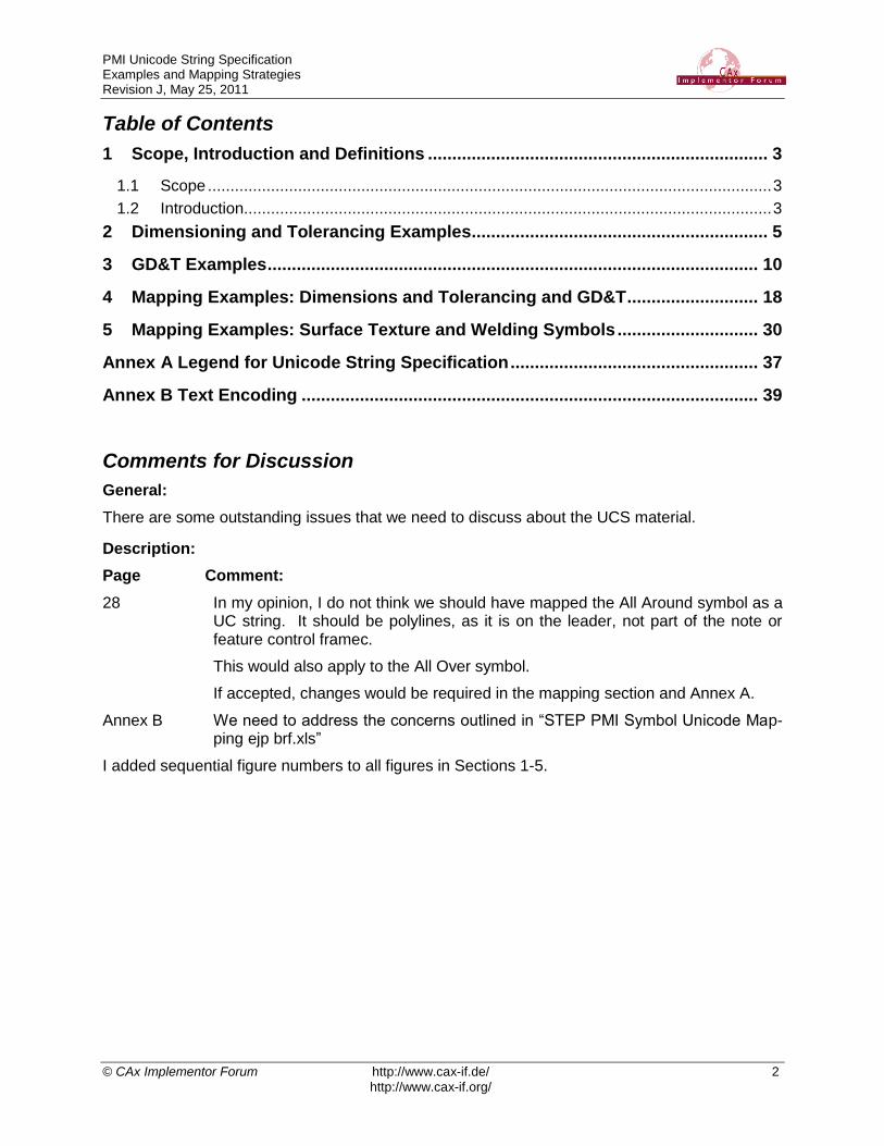
Dimensioning and Tolerancing and Screw Threads Examples - ASME Y14.5-2009
New Dimensioning and Tolerancing Symbols: Screw Threads - 2
Notes:
ASME Y14.5M-1994 and Y14.5-2009 have examples of similar dimensioning and tolerancing methods
as shown in items 1 - 4.
Inch screw thread specifications from ASME B1.1 - 2003.
Metric screw thread designations from ASME B1.13M - 2005.
These screw thread specifications are very simple examples, and do not represent an exhaustive set of
screw thread specifications.
1
2
3
4
Dimension and Tolerance with Independency Symbol
5
6
7
Ø1.000 ±.005
8
I
.025 A B C All-Over Symbol (with Profile Tolerance)
Ø1.000 ±.005
Ø1.50 ±.03SFSpotface Symbol (with Dimensions and Tolerances)
3X Ø1.000 ±.005 CF Continuous Feature Symbol (with Dimension and Tolerance)
3X .250-20 UNC-2B
Screw Thread - Inch - Unified National Series: Fractional
3X .250-28 UNF-3A
3X 1/4-20 UNC-2B
Screw Thread - Inch - Unified National Series
Decimal Designation
Coated Thread
Before and After Thread Size Designations
AFTER COATING:
MAX MAJOR DIAMETER .2500
MAX PITCH DIAMETER .2268
BEFORE COATING:
MAJOR DIAMETER .2494 - .2431 SPL
PITCH DIAMETER .2256 - .2235 SPL
5 3X M6 x 1 – 4g6g (22) Screw Thread - Metric - M Profile - External
with Gaging System
3X M6 x 1 - 5H6H Screw Thread - Metric - M Profile - Internal
Screw Thread - Inch - Unified National Series: Decimal
Advanced Dimensional Management LLC
Figure 2

PMI Unicode String Specification Examples and Mapping Strategies Revision J, May 25, 2011
© CAx Implementor Forum http://www.cax-if.de/ 7
http://www.cax-if.org/
Dimensioning and Tolerancing Examples - ISO 129-1:2006 & ISO 406:1987
Dimensioning and Tolerancing Examples - 3
Notes:
ASME Y14.5M-1994 and Y14.5-2009 include examples of similar dimensioning and tolerancing methods
as shown in items 1 - 4.
30 f7
30 f7-0,020
-0,041
30 f729,980
29,959
+ 0,01
- 0,1129,97
1
2
3
4
Basic Size Dimension, Tolerance Symbol
Basic Size Dimension, Tolerance Symbol, Deviations
(Tolerances)
(in parentheses)
Basic Size Dimension, Tolerance Symbol, Limits of Size (in
parentheses)
Basic Size Dimension, Deviations (Tolerances)
5
Basic Size Dimension, Deviations (Tolerances)
Example of Dimensioning of Mating Features on an Assembly
hole Ø30 F7+0,041
+0,020shaft Ø30 h6
0
-0,013
6
Basic Size Dimension, Tolerance Symbol, Deviations
(Tolerances), Envelope Requirement
30 f7-0,020
-0,041E
7Projected Tolerance Zone Symbol, Projection Distance30,75P
t = 1,28
Thickness dimension of thin part, where thickness of part was
not modeled (from ISO 16792:2006)
9
Arc Length Symbol, Dimension Value30,75
Advanced Dimensional Management LLC
Figure 3

PMI Unicode String Specification Examples and Mapping Strategies Revision J, May 25, 2011
© CAx Implementor Forum http://www.cax-if.de/ 8
http://www.cax-if.org/
Dimensioning and Tolerancing Examples - ASME Y14.5M-1994
Complex Dimensioning and Tolerancing Examples - 4
1
2X Ø1.000 ±.005 BEFORE PLATING Ø1.0015 ±.0065 AFTER PLATING -001 ONLYST ST
3
2X Ø1.000 +.005-.003
1.50 +.04-.02
BEFORE PLATINGST ST
2X Ø 1.005.997
1.04.98
BEFORE PLATINGST ST
2X Ø .997 - 1.005 .98 - 1.04 BEFORE PLATINGST ST
2X Ø .997 - 1.005 1.04 MAX BEFORE PLATINGST ST
2X Ø30 f7 (29.98029.959
) 50 - 55.5 BEFORE PLATINGST ST
2
2X Ø1.000 ±.005 1.50 ±.03 BEFORE PLATINGST ST
2X Ø1.000 ±.005 BEFORE PLATING -001 ONLY
Ø1.0015 ±.0065 AFTER PLATING -001 ONLY
ST
ST
2X Ø1.000 ±.005 BEFORE PLATING
1.50 ±.03 BEFORE PLATING
ST
ST
2X Ø1.000 +.005-.003
BEFORE PLATING
1.50 +.04-.02
BEFORE PLATING
ST
ST
2X Ø 1.005.997
BEFORE PLATING
1.04.98
BEFORE PLATING
ST
ST
2X Ø .997 - 1.005 BEFORE PLATING
.98 - 1.04 BEFORE PLATINGST
ST
2X Ø .997 - 1.005 BEFORE PLATING
1.04 MAX BEFORE PLATINGST
ST
2X Ø30 f7 (29.98029.959
) BEFORE PLATING
50 - 55.5 BEFORE PLATING
ST
ST
4
5
6
7
Notes:
From these examples it is apparent that we cannot be sure which symbols and fields will be in which
position, as there are many, many variations of how a dimension and tolerance PMI may be formatted.
On a Single-Line
Vertically-Stacked
On a Single-Line
Vertically-Stacked
On a Single-Line
Vertically-Stacked
On a Single-Line
Vertically-Stacked
On a Single-Line
Vertically-Stacked
On a Single-Line
Vertically-Stacked
On a Single-Line
Vertically-Stacked
Advanced Dimensional Management LLC
Figure 4

PMI Unicode String Specification Examples and Mapping Strategies Revision J, May 25, 2011
© CAx Implementor Forum http://www.cax-if.de/ 9
http://www.cax-if.org/
Dimensioning and Tolerancing Examples - ISO 129-1:2006 & ISO 406:1987
Complex Dimensioning and Tolerancing Examples - 5
12x Ø30,5 ±0,12 BEFORE PLATING Ø30,6 ±0,14 AFTER PLATING -001 ONLY
3
2x Ø30 f7 (29,98029,959
) BEFORE PLATING Ø30,04029,999
AFTER PLATING
2
2x Ø30,5 ±0,12 BEFORE PLATING -001 ONLY
Ø30.6 ±0,14 AFTER PLATING -001 ONLY
Notes:
ISO dimensions and tolerances lack some of the potential complexity and variety possible when using
ASME Y14.5. However, there are still many possible variations within ISO dimensions and tolerances,
particularly in the use of tolerance symbols and the allowable reference values for tolerances or limits.
As with ASME dimensioning and tolerancing, there are many, many variations of how a dimension and
tolerance PMI may be formatted.
Items 3 & 4 are examples of dimensioning and tolerancing features on mating parts in an assembly.
On a Single-Line
Vertically-Stacked
Vertically-Stacked
EE
E
E
E E
On a Single-Line
2x Ø30 f7 (29,98029,959
) BEFORE PLATING
Ø30,04029,999
AFTER PLATING
E
E
hole Ø30 F7+0,041
+0,020shaft Ø30 h6
0
-0,013E E -001 ONLY
hole Ø30 F7+0,041
+0,020
shaft Ø30 h60
-0,013
E
E -001 ONLY
-001 ONLY Vertically-Stacked
On a Single-Line
4
hole Ø30 F7+0,041
+0,020shaft Ø30 h6
0
-0,013AFTER HEAT TREATING
hole Ø30 F7+0,041
+0,020
shaft Ø30 h60
-0,013
Vertically-Stacked
On a Single-Line
AFTER HEAT TREATING
AFTER HEAT TREATING
Advanced Dimensional Management LLC
Figure 5

PMI Unicode String Specification Examples and Mapping Strategies Revision J, May 25, 2011
© CAx Implementor Forum http://www.cax-if.de/ 10
http://www.cax-if.org/
3 GD&T Examples
2.75 A B C
Sample Feature Control Frames - ASME Y14.5M-1994
2.75 A B C
2.75 A B C
2.75 A B C
2.75 A
2.75
2.75 A B C
2.75 A B C
2.75 A
2.75
SØ2.75
SØ2.75 A
SØ2.75 A B C
SØ2.75 M A B C
SØ2.75 M A B CM M
Positional Tolerance RFS,
No DF References
Positional Tolerance RFS,
Primary DF RFS
Positional Tolerance RFS,
Primary DF RFS, Secondary DF RFS, Tertiary DF RFS
Positional Tolerance MMC,
Primary DF RFS, Secondary DF RFS, Tertiary DF RFS
Positional Tolerance MMC,
Primary DF RFS, Secondary DF MMC, Tertiary DF MMC
Positional Tolerance Ø, RFS,
No DF References
Positional Tolerance Ø, RFS,
Primary DF RFS
Positional Tolerance Ø, RFS,
Primary DF RFS, Secondary DF RFS, Tertiary DF RFS
Positional Tolerance Ø, MMC,
Primary DF RFS, Secondary DF RFS, Tertiary DF RFS
Positional Tolerance Ø, MMC,
Primary DF RFS, Secondary DF MMC, Tertiary DF MMC
Positional Tolerance SØ, RFS,
No DF References
Positional Tolerance SØ, RFS,
Primary DF RFS
Positional Tolerance SØ, RFS,
Primary DF RFS, Secondary DF RFS, Tertiary DF RFS
Positional Tolerance SØ, MMC,
Primary DF RFS, Secondary DF RFS, Tertiary DF RFS
Positional Tolerance SØ, MMC,
Primary DF RFS, Secondary DF MMC, Tertiary DF MMC
Positional Tolerance - 1: Single Segment
2
3
4
5
6
7
8
9
1
11
12
13
14
15
2.75 A B C Positional Tolerance Ø, LMC,
Primary DF RFS, Secondary DF LMC, Tertiary DF LMC16
2.75 A B C Positional Tolerance Ø, LMC,
Primary DF RFS, Secondary DF MMC, Tertiary DF MMC17
10
2.75 A B C Positional Tolerance Ø, LMC,
Primary DF RFS, Secondary DF RFS, Tertiary DF RFS18
2.75 A B C Positional Tolerance Ø, RFS,
Primary DF RFS, Secondary DF LMC, Tertiary DF MMC19
DF = Datum Feature
Advanced Dimensional Management LLC
Figure 6
PMI Unicode String Specification Examples and Mapping Strategies Revision J, May 25, 2011
© CAx Implementor Forum http://www.cax-if.de/ 11
http://www.cax-if.org/
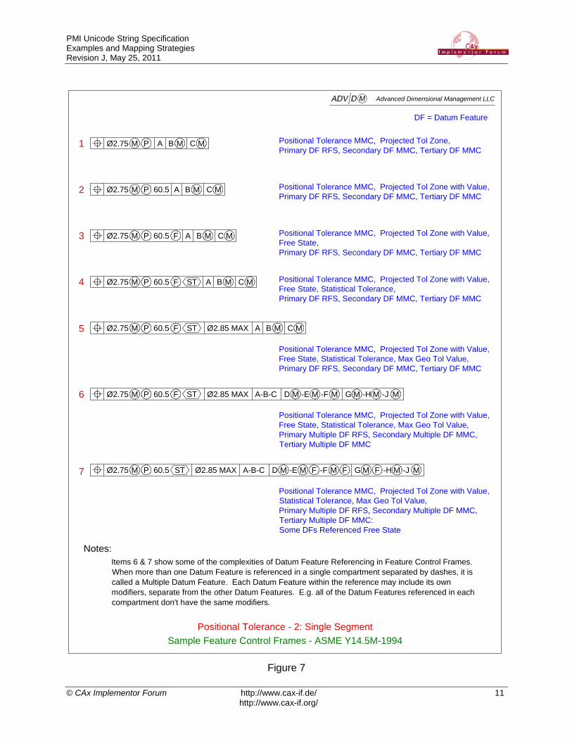
Sample Feature Control Frames - ASME Y14.5M-1994
Positional Tolerance - 2: Single Segment
Positional Tolerance MMC, Projected Tol Zone,
Primary DF RFS, Secondary DF MMC, Tertiary DF MMCØ2.75 M A B CM MP
Positional Tolerance MMC, Projected Tol Zone with Value,
Primary DF RFS, Secondary DF MMC, Tertiary DF MMCØ2.75 M A B CM MP 60.5
Ø2.75 M A B CM MP 60.5 F Positional Tolerance MMC, Projected Tol Zone with Value,
Free State,
Primary DF RFS, Secondary DF MMC, Tertiary DF MMC
Ø2.75 M A B CM MP 60.5 F Positional Tolerance MMC, Projected Tol Zone with Value,
Free State, Statistical Tolerance,
Primary DF RFS, Secondary DF MMC, Tertiary DF MMC
ST
Ø2.75 M A B CM MP 60.5 F ST Ø2.85 MAX
Positional Tolerance MMC, Projected Tol Zone with Value,
Free State, Statistical Tolerance, Max Geo Tol Value,
Primary DF RFS, Secondary DF MMC, Tertiary DF MMC
Ø2.75 M A-B-C D GM MP 60.5 F ST Ø2.85 MAX
Positional Tolerance MMC, Projected Tol Zone with Value,
Free State, Statistical Tolerance, Max Geo Tol Value,
Primary Multiple DF RFS, Secondary Multiple DF MMC,
Tertiary Multiple DF MMC
-E M -F M -H M -J M
Ø2.75 M A-B-C D GM MP 60.5 ST Ø2.85 MAX
Positional Tolerance MMC, Projected Tol Zone with Value,
Statistical Tolerance, Max Geo Tol Value,
Primary Multiple DF RFS, Secondary Multiple DF MMC,
Tertiary Multiple DF MMC:
Some DFs Referenced Free State
-E M -F M -H M -J MFF F
2
3
4
5
6
7
1
Notes:
Items 6 & 7 show some of the complexities of Datum Feature Referencing in Feature Control Frames.
When more than one Datum Feature is referenced in a single compartment separated by dashes, it is
called a Multiple Datum Feature. Each Datum Feature within the reference may include its own
modifiers, separate from the other Datum Features. E.g. all of the Datum Features referenced in each
compartment don't have the same modifiers.
DF = Datum Feature
Advanced Dimensional Management LLC
Figure 7

PMI Unicode String Specification Examples and Mapping Strategies Revision J, May 25, 2011
© CAx Implementor Forum http://www.cax-if.de/ 12
http://www.cax-if.org/
Sample Feature Control Frames - ASME Y14.5M-1994
Positional Tolerance - 3: Composite
Ø2.75 M A B CM M
Ø0.5
Ø2.75 M A B CM M
Ø0.5
Ø2.75 M A B C
Ø0.5 M A
Ø2.75 M A B CM M
Ø0.5 A
Ø2.75 M A B CM M
Ø0.5 A B CM M
Ø2.75 M A B CM M
Ø0.5 A B CM MM
Ø2.75 M A B CM M
Ø0.5 A B CM ML
Ø2.75 M A B CM M
Ø0.5 A B CM MM
P
P
Ø2.75 M A B CM M
Ø0.5 A B CM ML
P 60.5
F ST
Ø2.75 M A B CM M
Ø0.5 A B CM MM
P 60.5
P 60.5
Lower Compartment(s) Not-Aligned with Top
Upper Segment MMC, Lower Segment RFS,
No DF References in Lower Segment
Lower Compartment(s) Aligned with Top
Upper Segment MMC, Lower Segment RFS,
No DF References in Lower Segment
Lower Compartment(s) Aligned with Top
Upper Segment MMC, Lower Segment RFS,
Primary DF Reference in Lower Segment
Lower Compartment(s) Aligned with Top
Upper Segment MMC, Lower Segment RFS,
Primary, Secondary, Tertiary DF References in Lower Segment
Lower Compartment(s) Aligned with Top
Upper Segment MMC, Lower Segment MMC,
Primary DF Reference in Lower Segment
Lower Compartment(s) Aligned
Upper Segment MMC, Lower Segment MMC,
Primary, Secondary, Tertiary DF References in Lower Segment
Lower Compartment(s) Aligned
Upper Segment MMC, Lower Segment LMC,
Primary, Secondary, Tertiary DF References in Lower Segment
Lower Compartment(s) Aligned
Upper & Lower Segment MMC with Projected Tol Zone
Primary, Secondary, Tertiary DF References in Lower Segment
Lower Compartment(s) Aligned
Upper & Lower Segment MMC with Projected Tol Zone & Value
Primary, Secondary, Tertiary DF References in Lower Segment
Lower Compartment(s) Aligned
Upper Segment MMC with Projected Tol Zone & Value
Lower Segment LMC, Free State, Statistical Tolerance
Primary, Secondary, Tertiary DF References in Lower Segment
Ø2.75 M A B C
Ø0.5 M A
Lower Compartment(s) Aligned with Top
Upper Segment MMC, Lower Segment MMC,
Primary, Secondary DF References in Lower SegmentB
2
3
4
5
6
7
8
9
10
1
10
DF = Datum Feature
Advanced Dimensional Management LLC
Figure 8

PMI Unicode String Specification Examples and Mapping Strategies Revision J, May 25, 2011
© CAx Implementor Forum http://www.cax-if.de/ 13
http://www.cax-if.org/
Sample Feature Control Frames - ASME Y14.5M-1994
Positional Tolerance - 4: Composite
Ø2.75 M A B CM M
Ø0.85 A B CM MM
Ø0.25 AM
Ø2.75 M A B CM M
Ø0.8 A B CM MM
Ø0.25 AM
Ø0.1 M
Ø2.75 M A B C M
Ø0.8 A BL
Ø0.25 A
Ø0.1
P 60.5
F
Ø1.2 MAX
ST
Two Segments
Single DF Reference in Upper Segment,
No DF References in Lower Segment
Ø2.75 M A B C
Ø0.85 A BM
Ø0.25 AM
Ø2.75 M A B C
Ø0.85 A BM
Ø0.25 M
Ø2.75 M A B C
Ø0.85 AM
Ø0.25 M
Ø2.75 M A B
Ø0.85 AM
Ø0.25 M
Ø2.75 M A
Ø0.85 M
Three Segments
Three DF References in First Segment,
Two DF References in Second Segment,
One DF Reference in Third Segment
Three Segments
Three DF References in First Segment,
Two DF References in Second Segment,
No DF References in Third Segment
Three Segments
Three DF References in First Segment,
One DF Reference in Second Segment,
No DF References in Third Segment
Three Segments
Two DF References in First Segment,
One DF Reference in Second Segment,
No DF References in Third Segment
Three Segments
Three DF References in First Segment,
Three DF References in Second Segment,
One DF Reference in Third Segment
Four Segments
Three DF References in First Segment,
Three DF References in Second Segment,
One DF Reference in Third Segment
No DF References in Fourth Segment
Four Segments (Run and Hide)
First Segment: MMC, Projected, Three DF References,
Second Segment: LMC, Maximum Tol, Two DF References,
Third Segment: Free State, Statistical Tol, One DF Reference,
Fourth Segment: No DF References
2
3
4
5
6
7
8
1
DF = Datum Feature
Advanced Dimensional Management LLC
Figure 9

PMI Unicode String Specification Examples and Mapping Strategies Revision J, May 25, 2011
© CAx Implementor Forum http://www.cax-if.de/ 14
http://www.cax-if.org/
Sample Feature Control Frames - ASME Y14.5M-1994
Profile Tolerance - 1: Single-Segment and Composite
4.75 A B C
2 A B
0.8 A
2.75 / A-B-C FF D MST25
4.5 A B C
2.2 A B
2.75 / 25 X 25 A B C
2.75 / Ø25 A B C
2.75 / 25 A B C
2.75 / 25 A B CST
2.75 / A B C
4.5 A B
2.2 A B
CM M
M
2.75 / 25 X 25 A B CM M
4.75 A B C
2 A B
0.8 F A
ST
Single Segment
Unit-Basis w Extents,
Primary, Secondary, Tertiary DF References RFS
Single Segment
Unit-Basis w Extents,
Primary RFS, Secondary MMC, Tertiary MMC DF References
Single Segment
Unit-Basis w Ø Extents,
Primary, Secondary, Tertiary DF References RFS
Single Segment
Unit-Basis w Extents,
Primary, Secondary, Tertiary DF References RFS
Single Segment
Unit-Basis w Extents, Statistical Tol,
Primary, Secondary, Tertiary DF References RFS
Single Segment
Unit-Basis w Extents, Free State, Statistical Tol,
Primary, Secondary, Tertiary DF References RFS
F ST25
Single Segment
Unit-Basis w Extents, Free State, Statistical Tol,
Complex Multiple Primary, Secondary, Tertiary DF References
Two Segment Composite
Primary, Secondary, Tertiary DF References in Upper Segment
Primary, Secondary, DF References in Lower Segment
Two Segment Composite
3 DF References in Upper Segment, 2 referenced at MMC
2 DF References in Lower Segment. 1 referenced at MMC
Three Segment Composite
3 DF References in First Segment
2, DF References in Second Segment
1 DF Reference in Third Segment
Three Segment Composite
3 DF References in First Segment
Statistical Tol, 2 DF References in Second Segment
Free State, 1 DF Reference in Third Segment
-E M
2.75 / A-B FF C MST25Single Segment
Unit-Basis w Extents, Free State, Statistical Tol,
Complex Multiple Primary, Secondary, Tertiary DF References
-D-EM
1
2
3
4
5
6
7
8
9
10
11
12
Advanced Dimensional Management LLC
Figure 10

PMI Unicode String Specification Examples and Mapping Strategies Revision J, May 25, 2011
© CAx Implementor Forum http://www.cax-if.de/ 15
http://www.cax-if.org/
Sample Feature Control Frames - ASME Y14.5-2009
Profile Tolerance - 2: Single-Segment
2
3
4
5
6
7
8
9
10
4.5 AU 1.5
2.75 A-B-C G-H-JF D-E-F MSTU 0.75 / 25 x 25 [z,u,v] [x] [y,w][BASIC] [Ø12.1]
1
B CL L
NON-UNIFORM D E FM M
4.5 AU 1.5 F B CM
4.5 AU 1.5 F B [BASIC] C
4.5 AU 1.5 F B [BSC] C
4.5 U 1.5 F B [Ø10.505] CA
Single Segment
Unequally-Disposed,
Primary, Secondary, Tertiary DF References RMB, MMB, MMB
Single Segment
Unequally-Disposed,
Primary, Secondary, Tertiary DF References RMB, LMB, LMB
4.5 AU 1.5 B CM M
Single Segment
Unequally-Disposed, Free State,
Primary, Secondary, Tertiary DF References RMB, MMB, RMB
Single Segment
Unequally-Disposed, Free State,
Primary, Secondary, Tertiary DF References RMB, @ BASIC, RMB
Single Segment
Unequally-Disposed, Free State,
Primary, Secondary, Tertiary DF References RMB, @ BSC, RMB
Single Segment
Unequally-Disposed, Free State,
Primary, Secondary, Tertiary DF References RMB, @ Ø10.505, RMB
Single Segment
NON-UNIFORM Tol Zone,
Primary, Secondary, Tertiary DF References RMB, MMB, MMB
Single Segment [Run and Hide]
Unequally-Disposed, Unit Basis with Extents, Free State, Statistical Tol Zone,
Primary Multiple DF Reference A-B RMB & C BASIC with Translation Modifier, Secondary Multiple DF
Reference D-E RMB & F @ Ø12.1 , Tertiary Multiple DF Reference G-H RMB & J MMB: All three DF
References with Degree of Freedom Constraint Modifiers
3.75 D E FM MSingle Segment
Primary DF Reference RMB, Secondary DF Reference MMB with
Translation Modifier, Tertiary DF Reference MMB
3.75 D [z, u, v] E F [y, w]M [x]
Single Segment
Primary DF Reference RMB, Secondary DF Reference MMB, Tertiary
DF Reference RMB: All three DF References with Degree of Freedom
Constraint Modifiers
*
*
*
**
*** *** ***
Notes:
This page includes all of the new Feature Control Frame content defined in ASME Y14.5-2009.
[BASIC], [BSC], and [value] are new methods to override the default size/boundary for Datum Feature
Simulators. [BSC] is an abbreviation for [BASIC], which means the basic size / shape.
is the Datum Feature Simulator Translation Modifier. This is used to indicate that a Datum Feature
Simulator moves (translates) until it contacts the as-produced part.
[x,y,z,u,v,w] are Degree of Freedom Constraint Modifiers. These are used to indicate which Degrees of
Freedom are eliminated by the Datum Feature Simulator, potentially overriding the default conditions.***
**
*
DF = Datum Feature
*** *** **** ***
Advanced Dimensional Management LLC
Figure 11

PMI Unicode String Specification Examples and Mapping Strategies Revision J, May 25, 2011
© CAx Implementor Forum http://www.cax-if.de/ 16
http://www.cax-if.org/
2,75 A B C
Sample Tolerance Frames - ISO 1101:2004
2,75 A B C
2,75 A B C
2,75 A B C
2,75 A
2,75
2,75 A B C
2,75 A B C
2,75 A
2,75
SØ2,75
SØ2,75 A
SØ2,75 A B C
SØ2,75 M A B C
SØ2,75 M A B CM M
Position Tolerance RFS,
No DF References
Position Tolerance RFS,
Primary DF RFS
Position Tolerance RFS,
Primary DF RFS, Secondary DF RFS, Tertiary DF RFS
Position Tolerance MMC,
Primary DF RFS, Secondary DF RFS, Tertiary DF RFS
Position Tolerance MMC,
Primary DF RFS, Secondary DF MMR, Tertiary DF MMR
Position Tolerance Ø, RFS,
No DF References
Position Tolerance Ø, RFS,
Primary DF RFS
Position Tolerance Ø, RFS,
Primary DF RFS, Secondary DF RFS, Tertiary DF RFS
Position Tolerance Ø, MMC,
Primary DF RFS, Secondary DF RFS, Tertiary DF RFS
Position Tolerance Ø, MMC,
Primary DF RFS, Secondary DF MMR, Tertiary DF MMR
Position Tolerance SØ, RFS,
No DF References
Position Tolerance SØ, RFS,
Primary DF RFS
Position Tolerance SØ, RFS,
Primary DF RFS, Secondary DF RFS, Tertiary DF RFS
Position Tolerance SØ, MMC,
Primary DF RFS, Secondary DF RFS, Tertiary DF RFS
Position Tolerance SØ, MMC,
Primary DF RFS, Secondary DF MMR, Tertiary DF MMR
Position Tolerance Examples - 1
2
3
4
5
6
7
8
9
1
11
12
13
14
15
2,75 A B C Position Tolerance Ø, LMC,
Primary DF RFS, Secondary DF LMR, Tertiary DF LMR16
2,75 A B C Position Tolerance Ø, LMC,
Primary DF RFS, Secondary DF MMR, Tertiary DF MMR17
10
2,75 A B C Position Tolerance Ø, LMC,
Primary DF RFS, Secondary DF RFS, Tertiary DF RFS18
2,75 A B C Position Tolerance Ø, RFS,
Primary DF RFS, Secondary DF LMR, Tertiary DF MMR19
DF = Datum Feature
Advanced Dimensional Management LLC
Figure 12
PMI Unicode String Specification Examples and Mapping Strategies Revision J, May 25, 2011
© CAx Implementor Forum http://www.cax-if.de/ 17
http://www.cax-if.org/
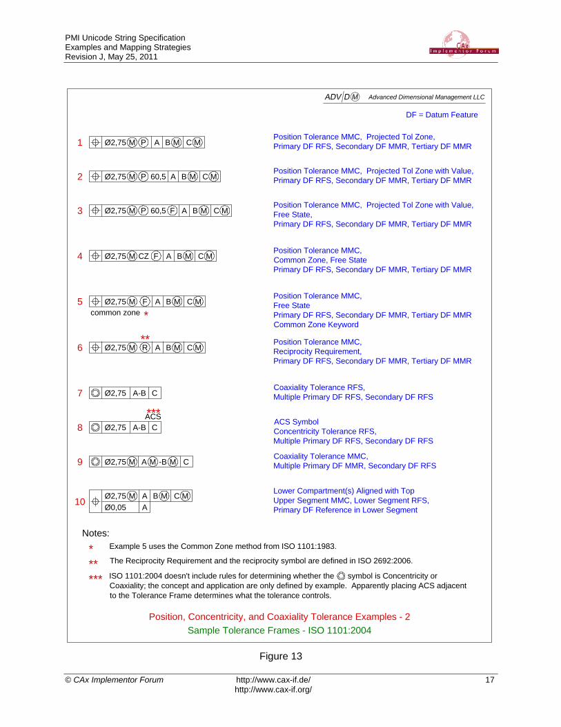
Sample Tolerance Frames - ISO 1101:2004
Position, Concentricity, and Coaxiality Tolerance Examples - 2
Position Tolerance MMC, Projected Tol Zone,
Primary DF RFS, Secondary DF MMR, Tertiary DF MMRØ2,75 M A B CM MP
Position Tolerance MMC, Projected Tol Zone with Value,
Primary DF RFS, Secondary DF MMR, Tertiary DF MMRØ2,75 M A B CM MP 60,5
Ø2,75 M A B CM MP 60,5 FPosition Tolerance MMC, Projected Tol Zone with Value,
Free State,
Primary DF RFS, Secondary DF MMR, Tertiary DF MMR
Ø2,75 A B CM MCZ FPosition Tolerance MMC,
Common Zone, Free State
Primary DF RFS, Secondary DF MMR, Tertiary DF MMR
2
3
4
7
8
10
1
Notes:
Example 5 uses the Common Zone method from ISO 1101:1983.
The Reciprocity Requirement and the reciprocity symbol are defined in ISO 2692:2006.
ISO 1101:2004 doesn't include rules for determining whether the symbol is Concentricity or
Coaxiality; the concept and application are only defined by example. Apparently placing ACS adjacent
to the Tolerance Frame determines what the tolerance controls.
M
Ø2,75 A-B CCoaxiality Tolerance RFS,
Multiple Primary DF RFS, Secondary DF RFS
Ø2,75 A-B CACS Symbol
Concentricity Tolerance RFS,
Multiple Primary DF RFS, Secondary DF RFS
Ø2,75 A B CM MFPosition Tolerance MMC,
Free State
Primary DF RFS, Secondary DF MMR, Tertiary DF MMR
Common Zone Keyword
5 M
common zone
ACS
*
*
***
**
Ø2,75 M A B CM M
Ø0,05 A
Lower Compartment(s) Aligned with Top
Upper Segment MMC, Lower Segment RFS,
Primary DF Reference in Lower Segment
6
9
Ø2,75 A B CM MRPosition Tolerance MMC,
Reciprocity Requirement,
Primary DF RFS, Secondary DF MMR, Tertiary DF MMR
M**
***
Ø2,75 A CCoaxiality Tolerance MMC,
Multiple Primary DF MMR, Secondary DF RFS-BM MM
DF = Datum Feature
Advanced Dimensional Management LLC
Figure 13

PMI Unicode String Specification Examples and Mapping Strategies Revision J, May 25, 2011
© CAx Implementor Forum http://www.cax-if.de/ 18
http://www.cax-if.org/
4 Mapping Examples: Dimensions and Tolerancing and GD&T
Dimensioning and Tolerancing Examples - ASME Y14.5M-1994
Mapping - 3: Treating Content as a Single String
DIM\wØ1.000 ±.005Ø1.000 ±.005
Ø1.000 +.005-.002
1
2
1
Dimension with Equal-Bilateral Tolerance
Unicode String:
DIM\wØ1.000 \u+.005\n-.002\u
1
Dimension with Unequal-Bilateral Tolerance
Unicode String:
Ø1.005 .995
3
4
6
DIM\wØ\u1.005\n.995\u
Limit Dimension with Ø Symbol
Unicode String:
Limit Dimension
1.005 .995
DIM\w\u1.005\n.995\u
Unicode String:
Ø.995 - 1.005
1
DIM\wØ.995 - 1.005
Limit Dimension Horizontal Format
Unicode String:
5N/A
1
1
Note:
I recommend that we treat the entire dimension string as a single entity. Thus, Ø.505 ±.010 would be a single entity,
rather than 3 entities. For example:
Preferred Ø.505 ±.010 Not-Preferred Ø.505 ±.010
Unicode String: DIM\wØ.505±.010 Unicode String: DIM\wØ\w.505\w±.010
Items 5 & 6 illustrated optional approaches of how to map a horizontal limit dimension. Item 6 was the preferable
method, and is the method shown here. Item 5 is not needed.
1 21 3
Advanced Dimensional Management LLC
Figure 14

PMI Unicode String Specification Examples and Mapping Strategies Revision J, May 25, 2011
© CAx Implementor Forum http://www.cax-if.de/ 19
http://www.cax-if.org/
Dimensioning and Tolerancing Examples - ASME Y14.5M-1994
Mapping - 4: Treating Content as a Single String
DIM\wØ.995 - 1.005
1.005 MAX
(Ø1.000 ±.005)
1
2
Dimension with Arc Length Symbol: Option 1
Unicode String:
3
4
5, 6
Reference Dimension with Tolerance
Single Limit Dimension
DIM\w1.005 MAX
Unicode String:
7
Ø.995 - 1.005
1
1
1
DIM\w(Ø1.000±.005)
Unicode String:
Ø1.000
Basic Dimension
DIM\wØ1.000
Unicode String:1
N/A
Note:
I recommend that we treat the entire dimension string as a single entity. Thus, Ø.505 ±.010 would be a single entity,
rather than 3 entities. For example:
Preferred Ø.505 ±.010 Not-Preferred Ø.505 ±.010
Unicode String: DIM\wØ.505±.010 Unicode String: DIM\wØ\w.505\w±.010
Items 5 & 6 are not needed.
1 21 3
N/A
Selected Method:
Arc is mapped
as a polyline
Advanced Dimensional Management LLC
Figure 15
PMI Unicode String Specification Examples and Mapping Strategies Revision J, May 25, 2011
© CAx Implementor Forum http://www.cax-if.de/ 20
http://www.cax-if.org/
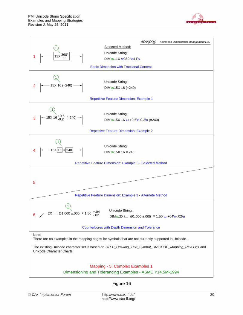
Dimensioning and Tolerancing Examples - ASME Y14.5M-1994
Mapping - 5: Complex Examples 1
1
2
3
4
6
Repetitive Feature Dimension: Example 1
5
11X 360°11 DIM\w11X \v360°\n11\v
Unicode String:
1
Basic Dimension with Fractional Content
15X 16 (=240)
1
Repetitive Feature Dimension: Example 2
15X 16 = 240
15X 16 +0.5-0.2
(=240)
1
DIM\w15X 16 (=240)
Unicode String:
DIM\w15X 16 = 240
Unicode String:
DIM\w15X 16 \u +0.5\n-0.2\u (=240)
Unicode String:
Repetitive Feature Dimension: Example 3 - Selected Method
Repetitive Feature Dimension: Example 3 - Alternate Method
2X Ø1.000 ±.005 1.50 +.04-.02
Counterbores with Depth Dimension and Tolerance
DIM\w2X Ø1.000 ±.005 1.50 \u.+04\n-.02\u
Unicode String:
Note:
There are no examples in the mapping pages for symbols that are not currently supported in Unicode.
The existing Unicode character set is based on STEP_Drawing_Text_Symbol_UNICODE_Mapping_RevG.xls and
Unicode Character Charts.
1
1
Selected Method:
Advanced Dimensional Management LLC
Figure 16
PMI Unicode String Specification Examples and Mapping Strategies Revision J, May 25, 2011
© CAx Implementor Forum http://www.cax-if.de/ 21
http://www.cax-if.org/
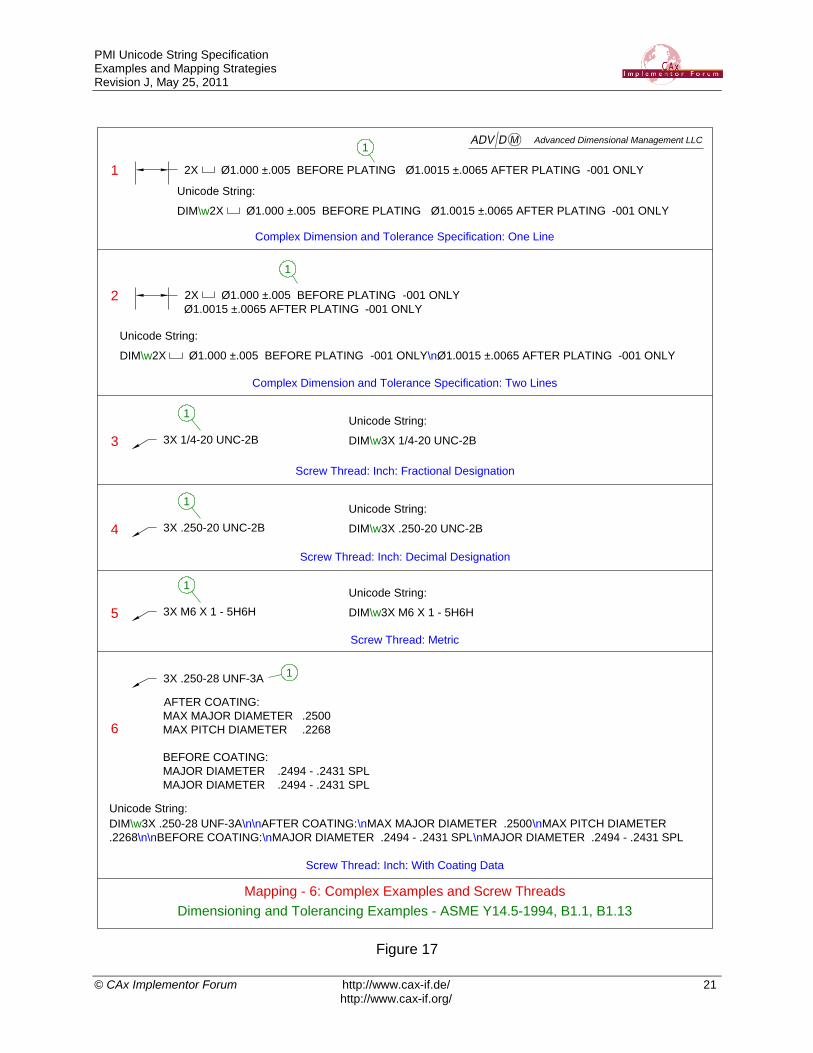
Dimensioning and Tolerancing Examples - ASME Y14.5-1994, B1.1, B1.13
Mapping - 6: Complex Examples and Screw Threads
1
2
3
4
6
DIM\w2X Ø1.000 ±.005 BEFORE PLATING Ø1.0015 ±.0065 AFTER PLATING -001 ONLY
Unicode String:
1
Complex Dimension and Tolerance Specification: One Line
Screw Thread: Inch: Fractional Designation
1
DIM\w3X 1/4-20 UNC-2B
Unicode String:
3X .250-20 UNC-2B
3X .250-28 UNF-3A
3X 1/4-20 UNC-2B
AFTER COATING:
MAX MAJOR DIAMETER .2500
MAX PITCH DIAMETER .2268
BEFORE COATING:
MAJOR DIAMETER .2494 - .2431 SPL
MAJOR DIAMETER .2494 - .2431 SPL
2X Ø1.000 ±.005 BEFORE PLATING Ø1.0015 ±.0065 AFTER PLATING -001 ONLY
DIM\w2X Ø1.000 ±.005 BEFORE PLATING -001 ONLY\nØ1.0015 ±.0065 AFTER PLATING -001 ONLY
1
2X Ø1.000 ±.005 BEFORE PLATING -001 ONLY
Ø1.0015 ±.0065 AFTER PLATING -001 ONLY
Unicode String:
Complex Dimension and Tolerance Specification: Two Lines
Screw Thread: Inch: Decimal Designation
1
DIM\w3X .250-20 UNC-2B
Unicode String:
5 3X M6 X 1 - 5H6H
Screw Thread: Metric
1
DIM\w3X M6 X 1 - 5H6H
Unicode String:
1
DIM\w3X .250-28 UNF-3A\n\nAFTER COATING:\nMAX MAJOR DIAMETER .2500\nMAX PITCH DIAMETER
.2268\n\nBEFORE COATING:\nMAJOR DIAMETER .2494 - .2431 SPL\nMAJOR DIAMETER .2494 - .2431 SPL
Unicode String:
Screw Thread: Inch: With Coating Data
Advanced Dimensional Management LLC
Figure 17

PMI Unicode String Specification Examples and Mapping Strategies Revision J, May 25, 2011
© CAx Implementor Forum http://www.cax-if.de/ 22
http://www.cax-if.org/
Dimensioning and Tolerancing Examples - ISO 129-1:2006 & ISO 406:1987
Mapping - 7: Complex Examples
1
2
Unicode String:
1
Basic Size with Deviations
30 f7-0,020
-0,041
30 f729,980
29,959
DIM\w30 f7 (\u-0,020\n-0,041\u)
Unicode String:
DIM\w30 f7 (\u29,980\n29,959\u)
1
30 f7-0,020
-0,041E
3Unicode String:
DIM\w30 f7 (\u-0,020\n-0,041\u)
Basic Size with Limits of Size
Basic Size with Deviations and Envelope Requirement
hole Ø30 F7+0,041
+0,020shaft Ø30 h6
0
-0,0134
Unicode String:
DIM\w30 F7 (\u+0,041\n+0,020\u) shaft Ø30 h6 (\u0\n-0,013\u)
Basic Size with Deviations for Hole and Shaft in Assembly
1
1
30,75P5 Unicode String:
DIM\w 30,75
Projected Tolerance Zone Dimension
t = 1,2
5 Unicode String:
DIM\wt = 1,2
Thickness Dimension (where thickness of part was not modeled)
1
1
E
Advanced Dimensional Management LLC
Figure 18
PMI Unicode String Specification Examples and Mapping Strategies Revision J, May 25, 2011
© CAx Implementor Forum http://www.cax-if.de/ 23
http://www.cax-if.org/
Dimensioning and Tolerancing Examples - ASME Y14.5M-1994
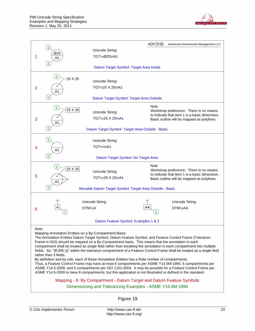
Mapping - 8: By Compartment - Datum Target and Datum Feature Symbols
TGT\wØ25\nA11
2
Datum Target Symbol: Target Area Inside
Unicode String:
3
Note:
Mapping Annotation Entities on a By-Compartment Basis:
The Annotation Entities Datum Target Symbol, Datum Feature Symbol, and Feature Control Frame (Tolerance
Frame in ISO) should be mapped on a By-Compartment basis. This means that the annotation in each
compartment shall be treated as single field rather than breaking the annotation in each compartment into multiple
fields. So, "Ø.005 " within the tolerance compartment of a Feature Control Frame shall be treated as a single field
rather than 3 fields.
By definition and by rule, each of these Annotation Entities has a finite number of compartments.
Thus, a Feature Control Frame may have at most 6 compartments per ASME Y14.5M-1994, 5 compartments per
ASME Y14.5-2009, and 5 compartments per ISO 1101:2004. It may be possible for a Feature Control Frame per
ASME Y14.5-2009 to have 8 compartments, but this application is not illustrated or defined in the standard.
A1
Ø25
1
2
TGTw25 X 25\nA1
Datum Target Symbol: Target Area Outside
Unicode String:
A1
1
2
25 X 25
TGT\w25 X 25\nA1
Datum Target Symbol: Target Area Outside - Basic
Unicode String:
A1
1
2
25 X 25
TGT\w25 X 25\nA1
Movable Datum Target Symbol: Target Area Outside - Basic
Unicode String:
A1
1
2
25 X 25
4
A DTM\wA
Datum Feature Symbol: Examples 1 & 2
Unicode String:
5
1
Datum Target Symbol: No Target Area
6AA DTM\wAA
Unicode String:
1
A1
2
1
TGT\w\nA1
Unicode String:
Note
Workshop preference. There is no means
to indicate that item 1 is a basic dimension.
Basic outline will be mapped as polylines.
Note
Workshop preference. There is no means
to indicate that item 1 is a basic dimension.
Basic outline will be mapped as polylines.
Advanced Dimensional Management LLC
Figure 19

PMI Unicode String Specification Examples and Mapping Strategies Revision J, May 25, 2011
© CAx Implementor Forum http://www.cax-if.de/ 24
http://www.cax-if.org/
Dimensioning and Tolerancing Examples - ASME Y14.5M-1994
Mapping - 9: Feature Control Frames
FCF\w \wØ2.75 \wØ2.85 MAX\wA\wB \wC1
2
Feature Control Frame: Single Segment: With Maximum Number of Compartments
Unicode String:
3
Note:
We need to decide if we want to number the compartment fields for Feature Control Frames using Fixed or Variable
Numbering as shown above.
1
4
5
2 3 5 6
Feature Control Frame: Single Segment: Option 1 - Variable Compartment Numbering
FCF\w \wØ2.75 \wA\wB \wC
Unicode String:1
2.75 A B C
2 3 4 5
FCF\w \wØ2.75 \w\wA\wB \wC
Unicode String:1
2.75 A B C
2 4 5 6
Feature Control Frame: Single Segment: Option 2 - Fixed Compartment Numbering
Ø2.75 M AØ2.85 MAX B M C M
4
Note
Compartments numbered
consecutively, even though
one possible compartment
was not used.
Note
Compartments numbered to
correspond to the 6 possible
compartments.
(Compartment 3 is missing.)
Feature Control Frame: Single Segment: Option 1 - Variable Compartment Numbering
FCF\w \w.010\wA
Unicode String:1
.010 A
2
Unicode String:
Feature Control Frame: Single Segment: Option 2 - Fixed Compartment Numbering
3
1
.010 A
2 4
FCF\w \w.010\w\wA\w\w
6
7
Feature Control Frame: Single Segment: Option 1 - Variable Compartment Numbering
FCF\w \w.015
Unicode String:1
.015
2
Unicode String:
Feature Control Frame: Single Segment: Option 2 - Fixed Compartment Numbering
1
.015
2
FCF\w \w.015\w\w\w\w
Advanced Dimensional Management LLC
Figure 20

PMI Unicode String Specification Examples and Mapping Strategies Revision J, May 25, 2011
© CAx Implementor Forum http://www.cax-if.de/ 25
http://www.cax-if.org/
Dimensioning and Tolerancing Examples - ASME Y14.5M-1994
Mapping - 10: Complex and Other Feature Control Frames
FCF\w \wØ2.75 60.5 \w2.85 MAX\wA\wB \wC
1
2
Feature Control Frame: Single Segment: Complex Content
Unicode String:
3
Note:
The examples on this page use variable compartment Numbering for Feature Control Frames.
1
4
5
2 3 5 64
Feature Control Frame: Single Segment: Straightness - Unit-Basis
FCF\w \wØ.010 / 1.25
Unicode String:
6
Feature Control Frame: Single Segment: Profile of a Surface
Ø2.75 M A B CM MP 60.5 F Ø2.85 MAX
F
FCF\w \wØ2.75 60.5\w2.85 MAX\wA-B-C\wD -E -F \wG -H -J
Feature Control Frame: Single Segment: Complex Content
Unicode String:
Ø2.75 M A-B-C D GM MP 60.5 Ø2.85 MAX -E M -F M -H M -J MFF F
1 2 3 5 64
F F F
FCF\w \wØ.015 \wA
Unicode String:
Feature Control Frame: Single Segment: Perpendicularity
.015 A
1 2 3
.010 / 1.25
1 2
FCF\w \w.008\wA-B\wC
Unicode String:
Feature Control Frame: Single Segment: Total Runout
.008 A-B C
2 31 4
FCF\w \w.020\wA\wB \wC
Unicode String:
.020 A B C
2 31 4 5
Advanced Dimensional Management LLC
Figure 21

PMI Unicode String Specification Examples and Mapping Strategies Revision J, May 25, 2011
© CAx Implementor Forum http://www.cax-if.de/ 26
http://www.cax-if.org/
Dimensioning and Tolerancing Examples - ASME Y14.5M-1994
Mapping - 11: Composite Feature Control Frames
FCF\w \wØ2.75 60.5\w2.85 MAX\wA\wB \wC \nØ0.75 60.5\w0.85 MAX\wA\wB \wC
1
Composite Feature Control Frame: Complex - All Compartments Populated
Unicode String:
Note:
I propose to use the Mapping Scheme for Composite Feature Control Frames as shown above. The examples on
this page use Fixed compartment Numbering for Feature Control Frames.
Ø2.75 M A B CM M
Ø0.75 A
P 60.5
M
1 2 4 5 6
P 60.5
Ø2.85 MAX
Ø0.85 MAX
3
7 9 10 118
B CM M
FCF\w \wØ2.75 60.5\w2.85 MAX\wA\wB \wC \nØ0.75 60.5\wA
2
Unicode String:
Ø2.75 M A B CM M
Ø0.75 A
P 60.5
M
1 2 4 5 6
P 60.5
Ø2.85 MAX
3
7 8
Composite Feature Control Frame: Complex - All Compartments Not Populated
4.5 A B C
2.2 A BFCF\w \w4.5\wA\wB\wC\n2.2\wA\wB
3 Unicode String:
1 2 4 5
Composite Feature Control Frame: Profile of a Surface
7 86
4.5 A B C
0.2 / Ø25 AFCF\w \w4.5\wA\wB\wC\n0.2 / Ø25\wA
4 Unicode String:
1 2 3 4 5
Composite Feature Control Frame: Profile of a Surface with Unit-Basis
76
FCF\w \w.020\n.002 / .50 X .50
5 Unicode String:
1 2
Composite Feature Control Frame: Flatness with Unit Basis
3
.020
.002 / .50 X .50
3
Advanced Dimensional Management LLC
Figure 22

PMI Unicode String Specification Examples and Mapping Strategies Revision J, May 25, 2011
© CAx Implementor Forum http://www.cax-if.de/ 27
http://www.cax-if.org/
Dimensioning and Tolerancing Examples - ASME Y14.5M-1994
Mapping - 12: Composite Feature Control Frames: Complex
FCF\w \wØ2.75 60.5\w2.85 MAX\wA\wB \wC \nØ0.75 60.5\w0.85 MAX\wA\wB \wC
\nØ0.25\w0.35 MAX\wA
1
Composite Feature Control Frame: Complex: Position - Three Segments
Unicode String:
Note:
The examples on this page use variable compartment numbering for Feature Control Frames.
Ø2.75 M A B CM M
Ø0.75 A
P 60.5
M
1 2 4 5 6
P 60.5
Ø2.85 MAX
Ø0.85 MAX
3
7 9 10 118
B CM M
AØ0.25 Ø0.35 MAX
12 13 14
Second Segment
Third Segment
FCF\w \wØ2.75 \wA\wB \wC \nØ0.75 \wA\nØ0.25
2
Composite Feature Control Frame: Complex: Position - Three Segments
Unicode String:
Ø2.75 M A B CM M
Ø0.75 AM
1 2 3 4 5
6 7
Ø0.25
8
First Segment
Second Segment
Third Segment
FCF\w \w4.75\wA\wB\wC\n1.85\wA\wB\n0.35\wA
3
Composite Feature Control Frame: Complex: Position - Three Segments
Unicode String:
1 2 3 4 5
9
First Segment
Second Segment
Third Segment
4.75 A B C
1.85 A B
0.35 A
6 7 8
10
Advanced Dimensional Management LLC
First Segment
Figure 23

PMI Unicode String Specification Examples and Mapping Strategies Revision J, May 25, 2011
© CAx Implementor Forum http://www.cax-if.de/ 28
http://www.cax-if.org/
Dimensioning and Tolerancing Examples - ASME Y14.5M-1994 & ISO 1101
Mapping - 13: Annotation Sets: Related Entities as Individual Strings
FCF\w \w.025\wA\wB\wC
1
Feature Control Frame: Profile of a Surface - All Around
Note:
I propose that each separate line in a related set of Annotation Entities be mapped as a separate Unicode String as
shown above. The examples on this page use Variable compartment Numbering for Feature Control Frames.
.025 A B CAAS\w
All Around Symbol
Unicode Strings:
FCF\w \wØ.025 \wA\wB\wC
2
Size Dimension, Feature Control Frame and SIM REQT Keyword
.025 A B C
Unicode Strings:10X Ø.281
+.006-.001
2.25 ±.03
SIM REQT 1
DIM\w10X Ø.281 \u+.006\n-.001\u
TXT\wSIM REQT 1
DIM\w 2.25 ±.03
ASME
ASME
FCF\w \wØ.020 \wA\wB \wC
3
Pre- and Post-Finishing Size Dimensions and Feature Control Frame
Unicode Strings:
DIM\w3X Ø.502 - .504 BEFORE PLATING
DIM\w3X Ø.5035 - .5055 AFTER PLATING
ASME
3X Ø.502 - .504 BEFORE PLATING
3X Ø.5035 - .5055 AFTER PLATING
.020 A B C
Ø2,75 M A B CM MCZR
8x Ø30f7
4
Size Dimension and Feature Control Frame
Unicode Strings:
DIM\w8x Ø30f7
ISO 1101: 2004
FCF\w \wØ2,75 CZ\wA\wB \wCR
Size Dimension, Feature Control Frame and COMMON ZONE Keyword
Ø2,75 M A B CM MR
8x Ø30f7
5
Unicode Strings:
DIM\w8x Ø30f7
ISO 1101:1983
FCF\w \wØ2,75 \wA\wB \wCCOMMON ZONE
TXT\wCOMMON ZONE
R
1 3 4 5
1
1
1
2
1
1 3 4 52
1 1
1 3 4 52
1
1 3 4 52
1
1 3 4 52
1
Advanced Dimensional Management LLC
Figure 24
PMI Unicode String Specification Examples and Mapping Strategies Revision J, May 25, 2011
© CAx Implementor Forum http://www.cax-if.de/ 29
http://www.cax-if.org/
Dimensioning and Tolerancing Examples - ASME Y14.5M-1994 & ISO 1101
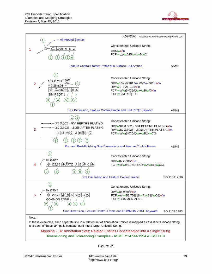
Mapping - 14: Annotation Sets: Related Entities Concatenated into a Single String
1
Feature Control Frame: Profile of a Surface - All Around
Note:
In these examples, each separate line in a related set of Annotation Entities is mapped as a distinct Unicode String,
and each of these strings is concatenated into a larger Unicode String.
.025 A B CAAS\w\x\n
FCF\w \w.025\wA\wB\wC
All Around Symbol
Concatenated Unicode String:
2
Size Dimension, Feature Control Frame and SIM REQT Keyword
.025 A B C
10X Ø.281 +.006-.001
2.25 ±.03
SIM REQT 1
DIM\w10X Ø.281 \u+.006\n-.001\u\x\n
DIM\w 2.25 ±.03\x\n
FCF\w \wØ.025 \wA\wB\wC\x\n
TXT\wSIM REQT 1
ASME
ASME
3
Pre- and Post-Finishing Size Dimensions and Feature Control Frame
DIM\w3X Ø.502 - .504 BEFORE PLATING\x\n
DIM\w3X Ø.5035 - .5055 AFTER PLATING\x\n
FCF\w \wØ.020 \wA\wB \wC
ASME
3X Ø.502 - .504 BEFORE PLATING
3X Ø.5035 - .5055 AFTER PLATING
.020 A B C
Ø2,75 M A B CM MCZR
8x Ø30f7
4
Size Dimension and Feature Control Frame
DIM\w8x Ø30f7\x\n
FCF\w \wØ2,75 CZ\wA\wB \wC
ISO 1101: 2004
R
Size Dimension, Feature Control Frame and COMMON ZONE Keyword
Ø2,75 M A B CM MR
8x Ø30f7
5DIM\w8x Ø30f7\x\n
FCF\w \wØ2,75 \wA\wB \wC \x\n
TXT\wCOMMON ZONE
ISO 1101:1983
COMMON ZONE
3 5 6 7
2
8
1
4
1
2 4 5 63
1 2
3 5 6 74
1
2 4 5 63
1
2 4 5 63
7
Concatenated Unicode String:
Concatenated Unicode String:
Concatenated Unicode String:
Concatenated Unicode String:
R
Advanced Dimensional Management LLC
Figure 25

PMI Unicode String Specification Examples and Mapping Strategies Revision J, May 25, 2011
© CAx Implementor Forum http://www.cax-if.de/ 30
http://www.cax-if.org/
5 Mapping Examples: Surface Texture and Welding Symbols
Unicode String Workshop 07/29 – 07/31 2009: Unicode String (UCS) Mapping Solutions for Surface Texture Symbols and Welding Symbols
Unicode String mapping solutions for Surface Texture Symbols and Welding Symbols were de-veloped at the UCS Workshop in Seattle July 29–31, 2009. ISO and ASME standards were consulted and solutions developed that work for both systems. These solutions follow.
Surface Texture Symbol Mapping:
Figure 26: Surface Texture Symbol Mapping Regions
Locations for Data entered into a Surface Texture Symbol are separated into distinct regions as shown above in Figure 26 Solutions are intended to work when mapping Surface Texture Sym-bols per ISO1302-2002 and ASME 14.36M – 1996 (R2008).
Keyword Names for Surface Texture Symbols:
Refer to Figure 27 for a graphical representation of UCS Surface Texture Symbol mapping.
SRFXXXY
Keyword
Material Removal Designation
All-Around
Figure 27: UCS Mapping for Surface Texture Symbols
General Mapping: Symbol Name + Suffix_1 (Optional) + Suffix_2 (Optional)

PMI Unicode String Specification Examples and Mapping Strategies Revision J, May 25, 2011
© CAx Implementor Forum http://www.cax-if.de/ 31
http://www.cax-if.org/
Symbol Name: SRF
Suffix_1: Material Removal Designation
APA Any Process Allowed
MRR Material Removal Required
NMR No Material Removed
Suffix_2: All-Around or Not All-Around
A All-Around
N Not All-Around
Keyword Examples Including Suffixes:
SRFAPAA Any Process Allowed, All-Around
SRFAPAN Any Process Allowed, Not All-Around
SRFMRRA Material Removal Required, All-Around
SRFMRRN Material Removal Required, Not All-Around
SRFNMRA No Material Removed, All-Around
SRFNMRN No Material Removed, Not All-Around
Refer to Figure 5 on page 6 of ASME 14.36M – 1996 (R2008) Surface Texture Symbols for the specifications that correspond to the following Unicode Strings.
Mapped Examples:
SRFAPA\w\w1.6\w\w\w0.8
SRFAPA\w\w1.6\r0.8\w\w\w0.8
SRFNMR\w\w1.6\w\w\w0.8
SRFAPA\w\w0.8\w\w\w2.5
SRFAPA\w\w0.2\w\w\w0.8\r2.5/R\u\rz\u0.8\r=
SRFAPA\w\w\w\w2.5/R\u\rz\u0.4
SRFAPA\w\w\w\w2.5/R\u\rz\u0.8
SRFAPA\w_\w0.8\w\w\w0.8\r_
SRFAPA\w\w0.8\w\w0.8/S\u\rM\u0.5\r_
SRFMRR\w\w1.6\w6\wNOTE X\w0.8
SRF\w1.6\r6\w0.8\wNOTE X

PMI Unicode String Specification Examples and Mapping Strategies Revision J, May 25, 2011
© CAx Implementor Forum http://www.cax-if.de/ 32
http://www.cax-if.org/
Surface Texture Symbol and Mapping Examples
1 Unicode String:
1
2
3
1.60.8 0.8
SRFAPA\w1.6\n0.8\w\w\w0.8
4
Surface Texture - All Around
2
Unicode String:
1
2
3
NOTE X1.6 0.8 SRFMRR\w1.6\w6\wNOTE X\w0.8
4
Surface Texture - Material Removal Prohibited
6
3
Unicode String:
1
2
3
0.8 SRFAPA\w0.8\w\w\w0.8/S\u\nM\u0.5\n
4
Surface Texture - Roughness Spacing & Perpendicular Lay
0.8/SM0.5
4a1 3
1.60.8
Surface Texture - Standard Orientation and Inverted
1.60.8
4b
Unicode String:
SRFAPA\w\u1.6\n0.8\u\w\w\w\u0.8\n2.5/RZ0.8\u
0.8
2.5/RZ0.8
2.5/RZ0.8
0.8
2 4
2 4
1 3
Unicode String:
SRFAPA\w\u0.8\n1.6\u\w\w\w\u2.5/RZ0.8\n0.8\u
Inverted Symbol,
Text Inverted
Inverted Symbol,
Text Not Inverted
Standard
Orientation
4c
0.81.6
0.8
2.5/RZ0.8
2 4
1 3
Unicode String:
SRFAPA\w\u1.6\n0.8\u\w\w\w\u0.8\n2.5/RZ0.8\u
Advanced Dimensional Management LLC
Figure 28

PMI Unicode String Specification Examples and Mapping Strategies Revision J, May 25, 2011
© CAx Implementor Forum http://www.cax-if.de/ 33
http://www.cax-if.org/
Welding Symbol Mapping:
Figure 29: Welding Symbol Mapping Regions
Locations for data entered into a Welding Symbol are separated into distinct regions as shown above in Figure 29 Solutions are intended to work when mapping Welding Symbols per ISO 2553 and AWS A2.4 standards for Welding Symbols.
Keyword Names for Surface Texture Symbols:
WLDXYZ
Keyword
Flag
All-Around
Reversed
Figure 30: UCS Mapping for Welding Symbols
General Mapping:
Symbol Name + Suffix_1 + Suffix_2 + Suffix_3
Symbol Name: WLD
Suffix_1: Flag, No Flag
F Flag N No Flag
Suffix_2: All Around, Not All Around
A All Around N Not All Around
Suffix 3: Reversed:
R Reversed

PMI Unicode String Specification Examples and Mapping Strategies Revision J, May 25, 2011
© CAx Implementor Forum http://www.cax-if.de/ 34
http://www.cax-if.org/
Figure 31: Welding Symbol Example
Keyword Examples Including Suffixes:
WLDFAR Flag, All-Around, Reversed
WLDNAR No Flag, All-Around, Reversed
WLDFNR Flag, Not All-Around, Reversed
WLDNNR No Flag, Not All-Around, Reversed
WLDFAN Flag, All-Around, (Not Reversed)
WLDNAN No Flag, All-Around, (Not Reversed)
WLDFNN Flag, Not All-Around, (Not Reversed)
WLDNNN No Flag, Not All-Around, (Not Reversed)
Mapped Examples:
UCS Mapping for welding specification in Figure 31.
WLDFAN\w\w.25\uF\n�\n�\u1.00-2.00\w.50\u�\n�\nH\u2.00-3.00\w10

PMI Unicode String Specification Examples and Mapping Strategies Revision J, May 25, 2011
© CAx Implementor Forum http://www.cax-if.de/ 35
http://www.cax-if.org/
Welding Symbol and Mapping Examples
1Unicode String:
WLDNNN\w\w\u20°\n\u\w\u\n10°\u
Welding Symbol - 6.3.3
Welding Symbol - 6.7.4.2
Welding Symbol - 7.3.1
20°
10°
1
2
3
4
2Unicode String:
WLDNNN\w\w\w\u\n\nR\u\w\uBACKING\nWELD\u
R1
2
3
4
BACKING
WELD
4Unicode String:
WLDNNN\w\w10\w1010
1
2
3
10
4
Welding Symbol - 6.7.4.2 - Reversed
3
Unicode String:
R 4
2
3
1
BACKING
WELDWLDNNR\w\uBACKING\nWELD\u\w\w\u\n\nR\u\w
Advanced Dimensional Management LLC
Figure 32

PMI Unicode String Specification Examples and Mapping Strategies Revision J, May 25, 2011
© CAx Implementor Forum http://www.cax-if.de/ 36
http://www.cax-if.org/
Welding Symbol and Mapping Examples
Welding Symbols - 10.6.2
6a Unicode String:
421
G
3
WLDNNR\w\w\w\u\n\nG\u
5aUnicode String:
WLDNNN\w\w\wØ2\u\n45°\u6
5bUnicode String:
WLDNNR\w\wØ25\u30°\n\n10\u10010
4
2
3
Welding Symbols - 8.1.3
6bUnicode String:
1 3
4C
2
WLDNNN\w\w\uC\n\n\u
6cUnicode String:4
1
WLDNNR\w\uMACHINE\nFLAT\u\w
3
2
MACHINE
FLAT
Ø25 100
30°1
12
3
Ø2 6
45°
4
Advanced Dimensional Management LLC
Figure 33

PMI Unicode String Specification Examples and Mapping Strategies Revision J, May 25, 2011
© CAx Implementor Forum http://www.cax-if.de/ 37
http://www.cax-if.org/
Annex A Legend for Unicode String Specification
Keyword Definitions:
Sample:
All-Around Symbol AAS All Over Symbol AOS
Datum Feature Symbol DTM Datum Target Symbol TGT Dimension DIM Feature Control Frame (ASME) FCF (Same as Tolerance Frame in ISO) Flag Note FLG Surface Texture Symbol SRF Tolerance Frame (ISO) FCF (Same as Feature Control Frame in ASME) Text TXT Welding Symbol WLD
Surface Texture Symbols: Standard Surface Finish: SRF e.g. SRF\w1.6\n6\w0.8\wNOTE X Any Process Allowed: SRFAPA e.g. SRFAPA\w\w1.6\w\w\w0.8 Material Removal Required: SRFMRR e.g. SRFMRR\w\w1.6\w6\wNOTE X\w0.8 No Material Removed: SRFNMR e.g. SRFNMR\w\w1.6\w\w\w0.8 A = All around N = Not all around SRFAPAA SRFAPAN SRFMRRA SRFMRRN SRFNMRA SRFNMRN
Welding:
Standard: WLD e.g. WLD\w⨡ ◯ \w.25\uF\n◠ \n⩗ \u1.00-2.00\w.50\uY\n◠ \nH\u2.00-3.00\w10
Reversed: WLDR

PMI Unicode String Specification Examples and Mapping Strategies Revision J, May 25, 2011
© CAx Implementor Forum http://www.cax-if.de/ 38
http://www.cax-if.org/
Unicode String Operator Definitions
\n New Line, Hard Return, Wrapping, or Soft Return
Use a hard carriage return to denote the following text occurs on a separate line. This is a literal carriage return because a new line of characters begins below the previous line, within the same string.
\n is also used as a separator between strings in a concatenated superstring. See page Mapping - 14: Annotation Sets: Related Entities Concatenated into a Single String in the Mapping Section of the report.
Use a soft return prior to text to denote a semantic separation. This would include texts and symbols that belong to a single string of text, and are on the same line, but are sym-bolically distinct. For example, the datum identifiers in a feature control frame. This sup-ports the top down left right rule that we have designated for this specification.
Example: FCF\w⌖ \w⌀ 2.75Ⓜ\wA\wBwC\n⌀ 0.50Ⓜ\wA\wB
\u Stack or upper/lower limits
This character set denotes a bilateral tolerance condition. Place the \u prior to the text appearing on the top to denote the end of the upper level text and at the end of the bot-tom end of the tolerance string to close.
Example: DIM\wØ1.000\u+.005\n-.002\u
\v Fraction
This character set is similar to the stack or upper and lower limits (\u) except it has a hor-izontal line between the limits. The example shown is on a Theoretically Exact Dimen-sional string.
Example: DIM\w11X \v360°\n11\v
\w Field or compartment separator
Unicode text strings are structured in several fields that are separated by \w character set. For annotation entities with compartmentalized data, the fields are mapped to corre-spond to the appropriate compartment in the annotation entity.
11X 360 11
Ø1.000 +.005 -.002
⌖
Ø2.75 Ⓜ B C A
B A Ø0.50 Ⓜ

PMI Unicode String Specification Examples and Mapping Strategies Revision J, May 25, 2011
© CAx Implementor Forum http://www.cax-if.de/ 39
http://www.cax-if.org/
Annex B Text Encoding
B.1 Placeholder for unspecified symbols
It may happen that when calculating the Unicode string for a given annotation, that annotation contains symbols which are not handled in this document. This may be the case e.g. when com-pany-specific guidelines are used to create the original PMI in the 3D model, or when product definition standards are used in this process which are out of scope for this document.
In this case, the unspecified symbols shall be replaced by a Unicode placeholder character, namely:
Unicode (X2 encoding, see 0): FFFD Shown as: �
B.2 \S\ characters
Within STEP Part 21, only printable characters are allowed as a part of a string. Within a string, \S\ denotes that the immediately following character represents a character with the binary value
128 higher. For example, \S\1 represents the plus-minus symbol. The character 1 in ASCII has
the binary representation equal to 49. The plus-minus symbol has the binary representation equal to 177.
The following are common characters which might be used by GD&T data.
Name Symbol Unicode
Copyright © \S\)
Degree ° \S\0
Diameter ⌀ \S\X
Plus-Minus ± \S\1
Pound Sterling £ \S\#
¬ \S\,
B.3 Unicode Symbols
Within STEP Part 21, Unicode characters can be defined within a string by an X2 encoding. If the characters ‘\X2\’ are found, they should be followed by one or more sets of 4 hexadecimal characters (0, 1, 2, 3, 4, 5, 6, 7, 8, 9, A, B, C, D, E, F). Each set of 4 hexadecimal characters represents a character or symbol defined by the Unicode tables (see www.unicode.org).
The following symbols might be used by GD&T data.

PMI Unicode String Specification Examples and Mapping Strategies Revision J, May 25, 2011
© CAx Implementor Forum http://www.cax-if.de/ 40
http://www.cax-if.org/
Name Symbol Unicode
Angularity ∠ 2220
Arc length ⌢ 2330
Between ↔ 2194
Cap Omega Ω 03A9
Center Line ℄ 2104
Circular Runout ↗ 2197
Circularity ○ 25CB
Concentricity ◎ 25CE
Conical Taper ⌲ 2332
Continuous Feature
Not yet in Unicode
Controlled Radius CR No Unicode (plain text)
Counterbore ⌴ 2334
Countersink ⌵ 2335
Cylindricity ⌭ 232D
Degree ° 00B0
Diameter ⌀ 2300
Depth ↧ 21A7
Envelope Requirement Ⓔ 24BA
Flatness
23E5
Free State Ⓕ 24BB
Independency Ⓘ 24BE
Least Material Condition Ⓛ 24C1
Max Material Condition Ⓜ 24C2
Parallelism // 2AFD
Perpendicularity
23CA
Plus/Minus ± 00B1
Position ⌖ 2316
Profile of a Line ⌒ 2312
Profile of a Surface ⌓ 2313
PMI Unicode String Specification Examples and Mapping Strategies Revision J, May 25, 2011
© CAx Implementor Forum http://www.cax-if.de/ 41
http://www.cax-if.org/
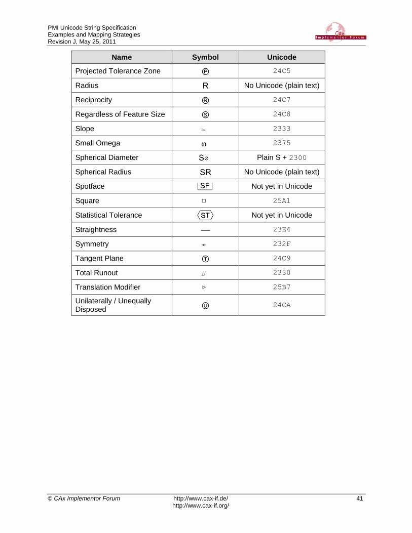
Name Symbol Unicode
Projected Tolerance Zone Ⓟ 24C5
Radius R No Unicode (plain text)
Reciprocity Ⓡ 24C7
Regardless of Feature Size Ⓢ 24C8
Slope ⌳ 2333
Small Omega ⍵ 2375
Spherical Diameter S⌀ Plain S + 2300
Spherical Radius SR No Unicode (plain text)
Spotface
Not yet in Unicode
Square □ 25A1
Statistical Tolerance
Not yet in Unicode
Straightness
23E4
Symmetry ⌯ 232F
Tangent Plane Ⓣ 24C9
Total Runout ⌰ 2330
Translation Modifier ▷ 25B7
Unilaterally / Unequally Disposed
Ⓤ 24CA
Related Documents
![UAX #15: Unicode Normalization Forms · 2008-01-29 · Chapter 2, General Structure, and . Chapter 3, Conformance, of . The Unicode Standard. in [Unicode]. In addition, the Unicode](https://static.cupdf.com/doc/110x72/5fae8045c121413ca15978cb/uax-15-unicode-normalization-2008-01-29-chapter-2-general-structure-and-.jpg)