Production Engineering 2/15/2015 Dept. of Mechanical Engineeering 1 PRODUCTION ENGINEERING 1. Module 1 – Theory of Metal Cutting 2. Module 2 – Thermal aspects of machining, Tool materials, Tool wear, Tool life, Economics of machining & Cutting fluids 3. Module 3 – Powder Metallurgy, Micromachining 4. Module 4 – Ceramics & Composites 5. Module 5 – Nontraditional machining & Material addition processes TEXTS • PRODUCTION ENGINEERING – Dr. P.C Sharma • PRODUCTION TECHNOLOGY – HMT • PRODUCTION TECHNOLOGY – R.K Jain • METAL CUTTING : THOERY AND PRACTICE – A Bhattacharyya Dept. of Mechanical Engineering 2 Dept. of Mechanical Engineering 3 • Introduction: – Manufacturing processes can be broadly classified in four major groups as follows: (a) Shaping or forming Manufacturing a solid product of definite size and shape from a given material taken in three possible states: in solid state – e.g., forging rolling, extrusion, drawing etc. in liquid or semi-liquid state – e.g., casting, injection moulding etc. in powder form – e.g., powder metallurgical process. (b) Joining process Welding, brazing, soldering etc. (c) Removal process Machining (Traditional or Non-traditional), Grinding etc. • Regenerative manufacturing Production of solid products in layer by layer from raw materials in different form: liquid – e.g., stereo lithography powder – e.g., selective sintering sheet – e.g., LOM (laminated object manufacturing) wire – e.g., FDM. (Fused Deposition Modelling) Dept. of Mechanical Engineering 4

PM- Module 1 Handout.pdf
Dec 25, 2015
INGHH
Welcome message from author
This document is posted to help you gain knowledge. Please leave a comment to let me know what you think about it! Share it to your friends and learn new things together.
Transcript
Production Engineering 2/15/2015
Dept. of Mechanical Engineeering 1
PRODUCTION ENGINEERING
1. Module 1 – Theory of Metal Cutting
2. Module 2 – Thermal aspects of machining, Tool materials, Tool
wear, Tool life, Economics of machining & Cutting
fluids
3. Module 3 – Powder Metallurgy, Micromachining
4. Module 4 – Ceramics & Composites
5. Module 5 – Nontraditional machining & Material addition processes
TEXTS
• PRODUCTION ENGINEERING – Dr. P.C
Sharma
• PRODUCTION TECHNOLOGY – HMT
• PRODUCTION TECHNOLOGY – R.K Jain
• METAL CUTTING : THOERY AND
PRACTICE – A Bhattacharyya
Dept. of Mechanical Engineering 2
Dept. of Mechanical Engineering 3
• Introduction:
– Manufacturing processes can be broadly classified in
four major groups as follows: (a) Shaping or forming Manufacturing a solid product of definite size and shape
from a given material taken in three possible states:
in solid state – e.g., forging rolling, extrusion, drawing etc.
in liquid or semi-liquid state – e.g., casting, injection moulding etc.
in powder form – e.g., powder metallurgical process.
(b) Joining process
Welding, brazing, soldering etc.
(c) Removal process
Machining (Traditional or Non-traditional), Grinding etc.
• Regenerative manufacturing Production of solid products in layer by layer
from raw materials in different form:
liquid – e.g., stereo lithography
powder – e.g., selective sintering
sheet – e.g., LOM (laminated object manufacturing)
wire – e.g., FDM. (Fused Deposition Modelling)
Dept. of Mechanical Engineering 4
Production Engineering 2/15/2015
Dept. of Mechanical Engineeering 2
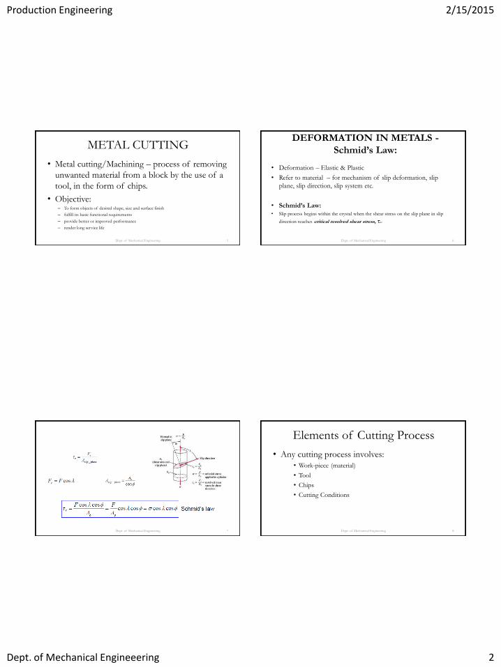
METAL CUTTING
Dept. of Mechanical Engineering 5
• Metal cutting/Machining – process of removing
unwanted material from a block by the use of a
tool, in the form of chips.
• Objective: – To form objects of desired shape, size and surface finish
– fulfill its basic functional requirements
– provide better or improved performance
– render long service life
DEFORMATION IN METALS -
Schmid’s Law:
• Deformation – Elastic & Plastic
• Refer to material – for mechanism of slip deformation, slip
plane, slip direction, slip system etc.
• Schmid’s Law:
• Slip process begins within the crystal when the shear stress on the slip plane in slip
direction reaches critical resolved shear stress, τC.
Dept. of Mechanical Engineering 6
Dept. of Mechanical Engineering 7
Elements of Cutting Process
• Any cutting process involves:
• Work-piece (material)
• Tool
• Chips
• Cutting Conditions
Dept. of Mechanical Engineering 8
Production Engineering 2/15/2015
Dept. of Mechanical Engineeering 3
Dept. of Mechanical Engineering 9
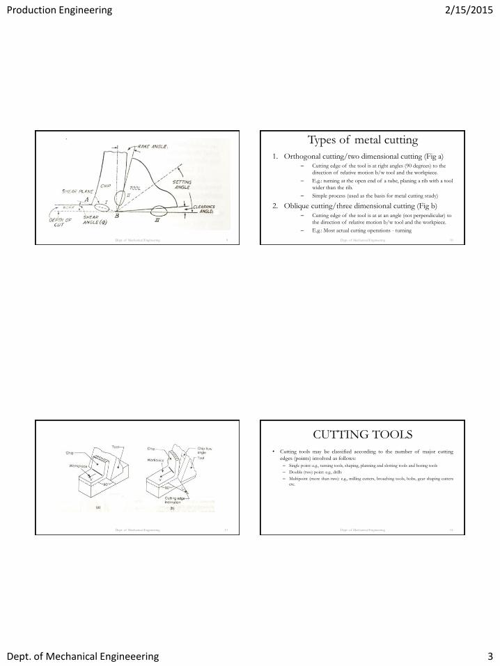
Types of metal cutting
1. Orthogonal cutting/two dimensional cutting (Fig a) – Cutting edge of the tool is at right angles (90 degrees) to the
direction of relative motion b/w tool and the workpiece.
– E.g.: turning at the open end of a tube, planing a rib with a tool
wider than the rib.
– Simple process (used as the basis for metal cutting study)
2. Oblique cutting/three dimensional cutting (Fig b) – Cutting edge of the tool is at at an angle (not perpendicular) to
the direction of relative motion b/w tool and the workpiece.
– E.g.: Most actual cutting operations - turning
Dept. of Mechanical Engineering 10
Dept. of Mechanical Engineering 11
CUTTING TOOLS
• Cutting tools may be classified according to the number of major cutting
edges (points) involved as follows:
– Single point: e.g., turning tools, shaping, planning and slotting tools and boring tools
– Double (two) point: e.g., drills
– Multipoint (more than two): e.g., milling cutters, broaching tools, hobs, gear shaping cutters
etc.
Dept. of Mechanical Engineering 12

Production Engineering 2/15/2015
Dept. of Mechanical Engineeering 4
Concepts of Rake and Relief Angles
Dept. of Mechanical Engineering 13
Rake and Clearance/Relief angle
• Rake angle (γ): Angle of inclination of rake surface from reference plane
• Relative advantages of such rake angles are:
– Positive rake – helps reduce cutting force and thus cutting power requirement.
– Negative rake – to increase edge-strength and life of the tool
– Zero rake – to simplify design and manufacture of the form tools.
• Clearance angle (α): Angle of inclination of clearance or flank surface from
the finished surface
– Clearance angle is essentially provided to avoid rubbing of the tool (flank) with the
machined surface which causes loss of energy and damages of both the tool and the job
surface. Hence, clearance angle is a must and must be positive (3o ~ 15o depending upon
tool-work materials and type of the machining operations like turning, drilling, boring etc.)
Dept. of Mechanical Engineering 14
Dept. of Mechanical Engineering 15
Systems of description of tool geometry
• Tool-in-Hand System
• Machine Reference System – ASA system
• Tool Reference Systems
∗ Orthogonal Rake System – ORS (ASSIGNMENT)
∗ Normal Rake System – NRS
• Work Reference System – WRS
Dept. of Mechanical Engineering 16
Production Engineering 2/15/2015
Dept. of Mechanical Engineeering 5
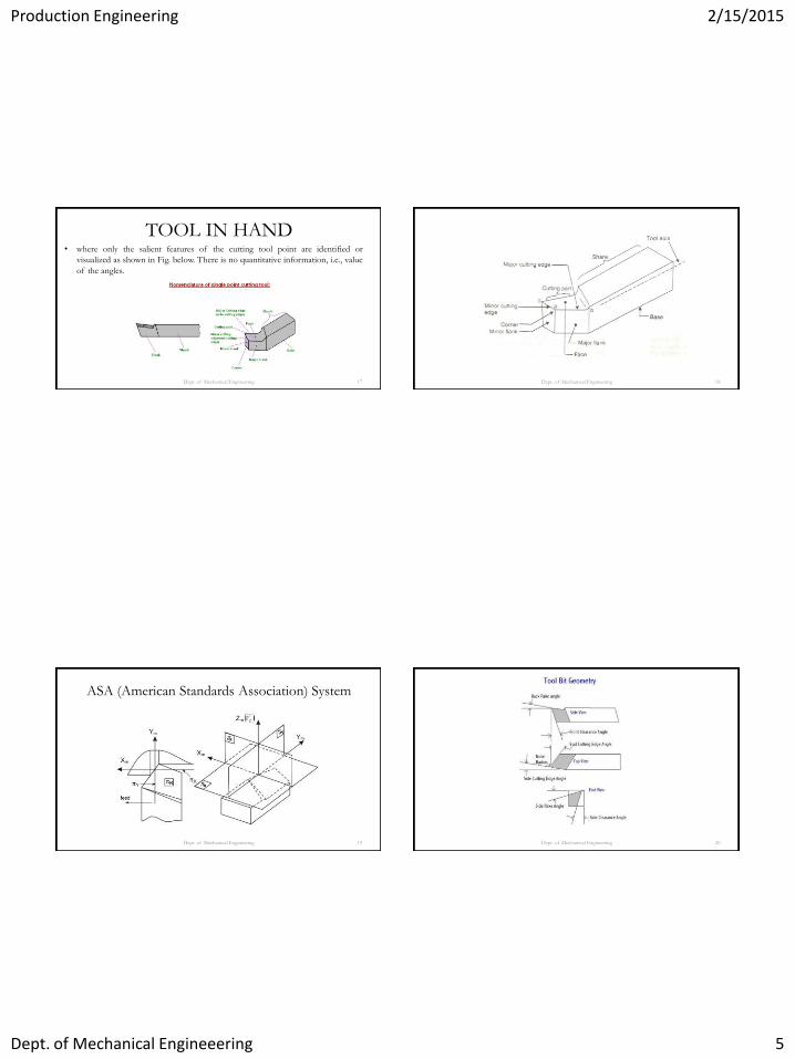
TOOL IN HAND • where only the salient features of the cutting tool point are identified or
visualized as shown in Fig. below. There is no quantitative information, i.e., value
of the angles.
Dept. of Mechanical Engineering 17 Dept. of Mechanical Engineering 18
ASA (American Standards Association) System
Dept. of Mechanical Engineering 19 Dept. of Mechanical Engineering 20

Production Engineering 2/15/2015
Dept. of Mechanical Engineeering 6
ASA System – Tool Angles
• Side cutting edge angle (SCEA) • Angle b/w the side cutting edge and the side of the tool shank
• Also called lead angle
• Protects the tip of the tool at the start of the cut
• Vary from 0-90 degrees
• Increased values – gives good tool life, but large values causes tool chatter
• Typical values- 15-30 degrees
• To produce a shoulder, 90 degree SCEA used.
Dept. of Mechanical Engineering 21
• End Cutting Edge Angle (ECEA) • Provides relief to the trailing edge to prevent rubbing or drag b/w the machined
surface and the non cutting part of the cutting edge.
• Too large an angle takes away material supporting the tool tip and conducting the heat,
making it fragile.
• May be from 8-15 degrees
• End cutting tools like necking tools have no ECEA
• Side relief and End relief angles (SRA & ERA) • Provided so that the flank of the tool clears the workpiece and no rubbing occurs
• Range from 5-15 degrees
• Small relief angles necessary to give strength to cutting edge to cut hard materials
• makes it easier to penetrate and cut the workpiece more efficiently, thus reducing the
cutting forces and power required.
• Too large – weakens the cutting edge, and results in poor heat conduction away.
Dept. of Mechanical Engineering 22
• Back Rake and Side Rake Angles – Affects the cutting angle and the shear angle.
– Large rake angle:
» Smaller the cutting angle (larger the shear angle); lower
cutting force and power
– Small rake angles ensures tool strength
– Practically is a compromise b/w the two.
– Generally,
• Hard materials – small rake angles
• Soft ductile materials – large rake angles (exception is
brass- small angles used to prevent digging)
Dept. of Mechanical Engineering 23
– Negative rake angles used for carbide inserts (brittle). Positive
rake angle directs the cutting force on the tool to the cutting
edge.
• Nose radius: – Required for long tool life and good surface finish
– Sharp edge – high stress, short life and leaves grooves in the
path of cut.
– Too large – result in tool chatter.
Dept. of Mechanical Engineering 24
Production Engineering 2/15/2015
Dept. of Mechanical Engineeering 7
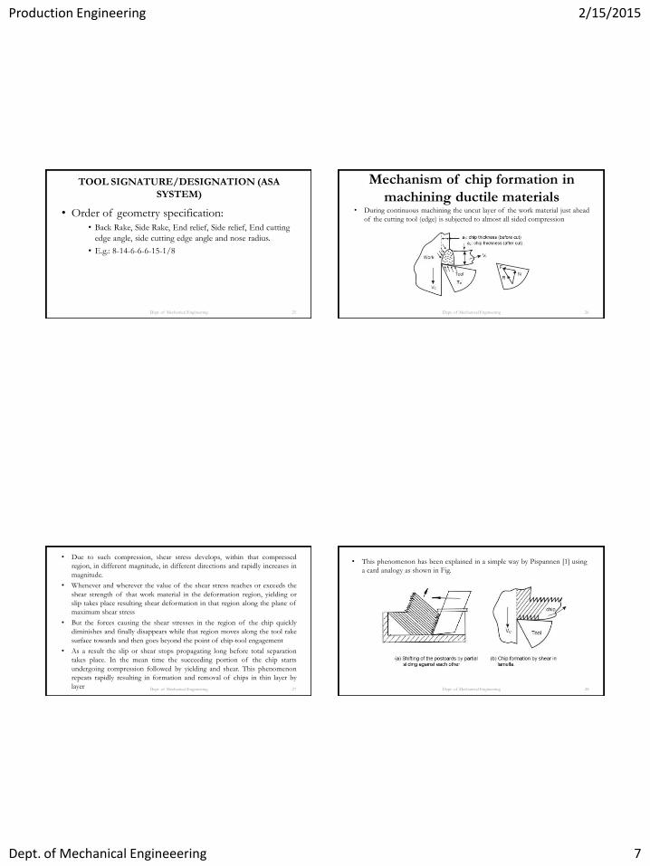
TOOL SIGNATURE/DESIGNATION (ASA
SYSTEM)
• Order of geometry specification:
• Back Rake, Side Rake, End relief, Side relief, End cutting
edge angle, side cutting edge angle and nose radius.
• E.g.: 8-14-6-6-6-15-1/8
Dept. of Mechanical Engineering 25
Mechanism of chip formation in
machining ductile materials
• During continuous machining the uncut layer of the work material just ahead
of the cutting tool (edge) is subjected to almost all sided compression
Dept. of Mechanical Engineering 26
• Due to such compression, shear stress develops, within that compressed
region, in different magnitude, in different directions and rapidly increases in
magnitude.
• Whenever and wherever the value of the shear stress reaches or exceeds the
shear strength of that work material in the deformation region, yielding or
slip takes place resulting shear deformation in that region along the plane of
maximum shear stress
• But the forces causing the shear stresses in the region of the chip quickly
diminishes and finally disappears while that region moves along the tool rake
surface towards and then goes beyond the point of chip-tool engagement
• As a result the slip or shear stops propagating long before total separation
takes place. In the mean time the succeeding portion of the chip starts
undergoing compression followed by yielding and shear. This phenomenon
repeats rapidly resulting in formation and removal of chips in thin layer by
layer Dept. of Mechanical Engineering 27
• This phenomenon has been explained in a simple way by Pispannen [1] using
a card analogy as shown in Fig.
Dept. of Mechanical Engineering 28
Production Engineering 2/15/2015
Dept. of Mechanical Engineeering 8
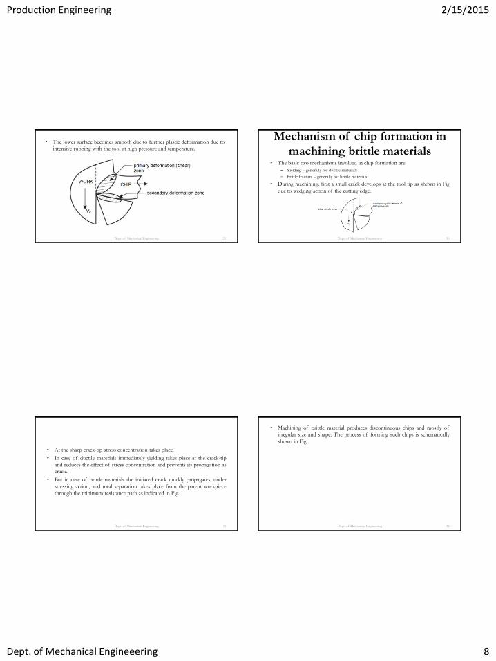
• The lower surface becomes smooth due to further plastic deformation due to
intensive rubbing with the tool at high pressure and temperature.
Dept. of Mechanical Engineering 29
Mechanism of chip formation in
machining brittle materials
• The basic two mechanisms involved in chip formation are
– Yielding – generally for ductile materials
– Brittle fracture – generally for brittle materials
• During machining, first a small crack develops at the tool tip as shown in Fig
due to wedging action of the cutting edge.
Dept. of Mechanical Engineering 30
• At the sharp crack-tip stress concentration takes place.
• In case of ductile materials immediately yielding takes place at the crack-tip
and reduces the effect of stress concentration and prevents its propagation as
crack.
• But in case of brittle materials the initiated crack quickly propagates, under
stressing action, and total separation takes place from the parent workpiece
through the minimum resistance path as indicated in Fig.
Dept. of Mechanical Engineering 31
• Machining of brittle material produces discontinuous chips and mostly of
irregular size and shape. The process of forming such chips is schematically
shown in Fig
Dept. of Mechanical Engineering 32

Production Engineering 2/15/2015
Dept. of Mechanical Engineeering 9
Types of Chips
• 4 types: 1. Discontinuous/Segmental chips
2. Continuous chips
3. Continuous chips with BUE (Built up Edge)
4. Non-homogeneous chips
Dept. of Mechanical Engineering 33
• Discontinuous/Segmental chips – Consists of separate plastically deformed segments
• Produced during machining of brittle materials like cast iron, bronze etc.
• Adv:
– Easy to handle
– Low power consumption
– Reasonable tool life
– Fair surface finish
• Produced in machining ductile materials under the following conditions:
» High depth of cut
» Low speed
» Small rake angle
– NOT DESIRABLE FOR DUCTILE MATERIALS (poor surface finish and
tool life)
Dept. of Mechanical Engineering 34
• Continuous chips – Metal continuously deforms without fracture and flows over the rake face in
the form of a ribbon
• Produced in machining ductile materials under the normal cutting speeds.
• Produced under:
– Small depth of cuts
– Normal to high cutting speeds
– Large rake angles
– Reduced friction along chip tool interface.
• Most desirable chip – indicates stable cutting, results in generally good surface
finish
• Disadv:
– Difficult to handle and dispose off..
– Chips coil in a helix (CHIP CURL), around the work and tool and may cause injury to the
operator when it breaks loose.
– Chip breakers are necessary
– More frictional heat is generated due to longer durations of chip contact with rake face.
Dept. of Mechanical Engineering 35
• Continuous chips with BUE
• Produced in machining ductile materials under conditions of:
– High local temperature and extreme pressures in the cutting zone
– High friction in the tool-chip interface
– Low cutting speed.
• Causes work material to adhere/weld to the cutting edge of the tool, forming the BUE
(further increasing friction)
• Successive layers of work material are added onto the BUE, till it becomes unstable and
breaks off. (some deposited on the work piece; some carried by the chip)
• Causes:
– Vibration - Larger power consumption
– Poor Surface Finish - Higher tool wear
• Can be avoided by:
– Increasing the cutting speed
– Increasing the rake angle
– Use of cutting fluids
Dept. of Mechanical Engineering 36

Production Engineering 2/15/2015
Dept. of Mechanical Engineeering 10
• Non-homogeneous chips
• Characterized by notches on the free side of the chip.
• Observed in:
– materials in which yield strength decreases with temperature.
– Materials having poor thermal conductivity.
• E.g. : Some steels and Ti Alloys at medium cutting speed.
• During the chip formation by slip along the shear plane, the
temperature also rise. This results in lowering of yield strength and
causes further strain.
• As the cutting is continued, a new shear plane will develop at some
distance and the deformation shifts to this point.
Dept. of Mechanical Engineering 37 Dept. of Mechanical Engineering 38
CHIP CURL
• Chips will develop a curvature (chip curl) as they leave the workpiece surface.
• Factors affecting the chip curl conditions are:
1. Distribution of stresses in the primary and secondary shear zones.
2. Thermal effects.
3. Work-hardening characteristics of the workpiece material
4. Gometry of the cutting tool
5. Cutting fluids
Dept. of Mechanical Engineering 39
Cutting Ratio/Chip Thickness Ratio (r)
• Denoted as ‘r’
• Also called chip compression factor
Considering an ideal 2D cutting operation
r = t/tc
where,
t = uncut of undeformed chip thickness
tc = chip thickness after metal is cut
Dept. of Mechanical Engineering 40
Production Engineering 2/15/2015
Dept. of Mechanical Engineeering 11
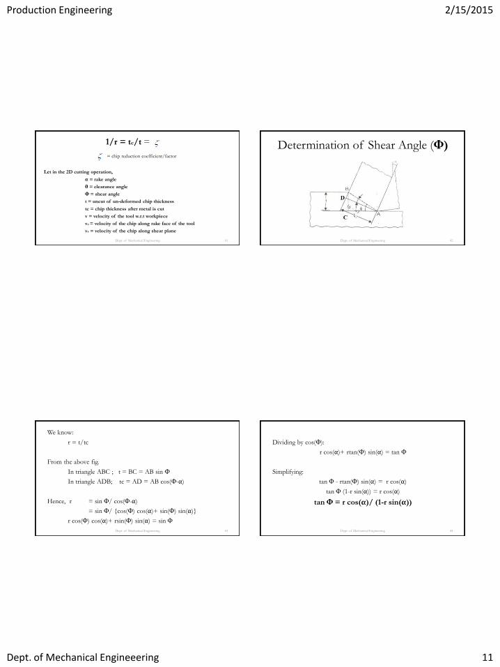
1/r = tc/t =
= chip reduction coefficient/factor
Let in the 2D cutting operation,
α = rake angle
θ = clearance angle
Φ = shear angle
t = uncut of un-deformed chip thickness
tc = chip thickness after metal is cut
v = velocity of the tool w.r.t workpiece
vc = velocity of the chip along rake face of the tool
vs = velocity of the chip along shear plane
Dept. of Mechanical Engineering 41
Determination of Shear Angle (Φ)
Dept. of Mechanical Engineering 42
We know:
r = t/tc
From the above fig.
In triangle ABC ; t = BC = AB sin Φ
In triangle ADB; tc = AD = AB cos(Φ-α)
Hence, r = sin Φ/ cos(Φ-α)
= sin Φ/ {cos(Φ) cos(α)+ sin(Φ) sin(α)}
r cos(Φ) cos(α)+ rsin(Φ) sin(α) = sin Φ
Dept. of Mechanical Engineering 43
Dividing by cos(Φ):
r cos(α)+ rtan(Φ) sin(α) = tan Φ
Simplifying:
tan Φ - rtan(Φ) sin(α) = r cos(α)
tan Φ (1-r sin(α)) = r cos(α)
tan Φ = r cos(α)/ (1-r sin(α))
Dept. of Mechanical Engineering 44
Production Engineering 2/15/2015
Dept. of Mechanical Engineeering 12
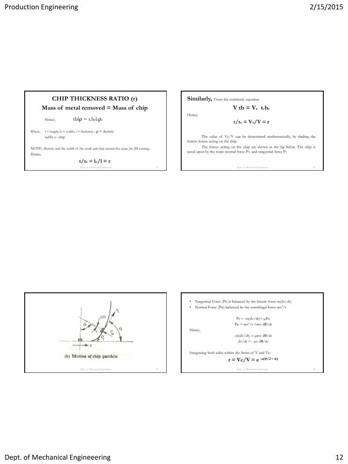
CHIP THICKNESS RATIO (r)
Mass of metal removed = Mass of chip
Hence, tblρ = tcbclcρc
Where, l = length; b = width; t = thickness ; ρ = density
suffix c- chip
NOTE: Density and the width of the work and chip remain the same (in 2D cutting).
Hence,
t/tc = lc/l = r
Dept. of Mechanical Engineering 45
Similarly, From the continuity equation
V tb = Vc tcbc
Hence,
t/tc = Vc/V = r
The value of Vc/V can be determined mathematically, by finding the
kinetic forces acting on the chip.
The forces acting on the chip are shown in the fig below. The chip is
acted upon by the static normal force PN and tangential force PT
Dept. of Mechanical Engineering 46
Dept. of Mechanical Engineering 47
• Tangential Force (Pt) is balanced by the kinetic force m(dv/dt)
• Normal Force (Pn) balanced by the centrifugal force mv2/r
Pt = -m(dv/dt)= µPn
Pn = mv2/r =mv dθ/dt
Hence,
-m(dv/dt) = µmv dθ/dt
dv/dt = - µv dθ/dt
Integrating both sides within the limits of V and Vc:
r = Vc/V = e -µ(π/2 – α)
Dept. of Mechanical Engineering 48
Production Engineering 2/15/2015
Dept. of Mechanical Engineeering 13
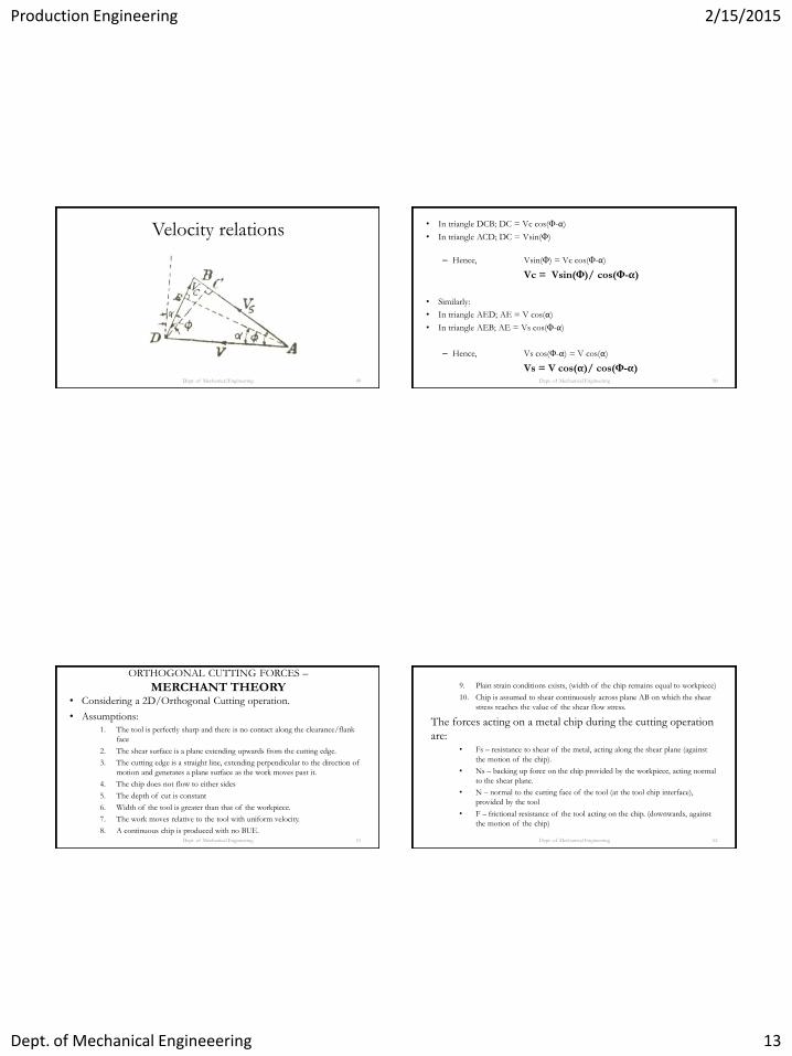
Velocity relations
Dept. of Mechanical Engineering 49
• In triangle DCB; DC = Vc cos(Φ-α)
• In triangle ACD; DC = Vsin(Φ)
– Hence, Vsin(Φ) = Vc cos(Φ-α)
Vc = Vsin(Φ)/ cos(Φ-α)
• Similarly:
• In triangle AED; AE = V cos(α)
• In triangle AEB; AE = Vs cos(Φ-α)
– Hence, Vs cos(Φ-α) = V cos(α)
Vs = V cos(α)/ cos(Φ-α)
Dept. of Mechanical Engineering 50
ORTHOGONAL CUTTING FORCES –
MERCHANT THEORY • Considering a 2D/Orthogonal Cutting operation.
• Assumptions:
1. The tool is perfectly sharp and there is no contact along the clearance/flank
face
2. The shear surface is a plane extending upwards from the cutting edge.
3. The cutting edge is a straight line, extending perpendicular to the direction of
motion and generates a plane surface as the work moves past it.
4. The chip does not flow to either sides
5. The depth of cut is constant
6. Width of the tool is greater than that of the workpiece.
7. The work moves relative to the tool with uniform velocity.
8. A continuous chip is produced with no BUE.
Dept. of Mechanical Engineering 51
9. Plain strain conditions exists, (width of the chip remains equal to workpiece)
10. Chip is assumed to shear continuously across plane AB on which the shear
stress reaches the value of the shear flow stress.
The forces acting on a metal chip during the cutting operation
are: • Fs – resistance to shear of the metal, acting along the shear plane (against
the motion of the chip).
• Ns – backing up force on the chip provided by the workpiece, acting normal
to the shear plane.
• N – normal to the cutting face of the tool (at the tool chip interface),
provided by the tool
• F – frictional resistance of the tool acting on the chip. (downwards, against
the motion of the chip)
Dept. of Mechanical Engineering 52
Production Engineering 2/15/2015
Dept. of Mechanical Engineeering 14
Dept. of Mechanical Engineering 53
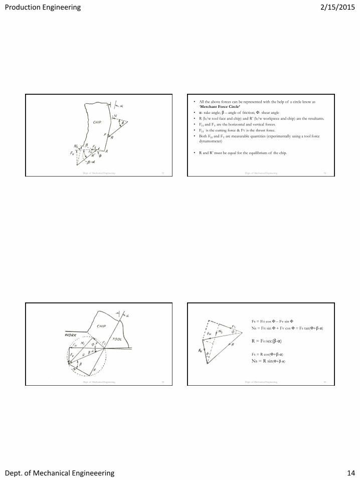
• All the above forces can be represented with the help of a circle know as
‘Merchant Force Circle’
• α- rake angle; β – angle of friction; Φ- shear angle
• R (b/w tool face and chip) and R’ (b/w workpiece and chip) are the resultants.
• FH and FV are the horizontal and vertical forces.
• FH is the cutting force & FV is the thrust force.
• Both FH and FV are measurable quantities (experimentally using a tool force
dynamometer)
• R and R’ must be equal for the equilibrium of the chip.
Dept. of Mechanical Engineering 54
Dept. of Mechanical Engineering 55
Fs = FH cos Φ – Fv sin Φ
Ns = FH sin Φ + Fv cos Φ = Fs tan(Φ+β-α)
R = FH sec(β-α)
Fs = R cos(Φ+β-α)
Ns = R sin(Φ+β-α)
Dept. of Mechanical Engineering 56

Production Engineering 2/15/2015
Dept. of Mechanical Engineeering 15
F = FH sin α + Fv cos α
N = FH cos α - Fv sin α
Dept. of Mechanical Engineering 57
Coefficient of friction (µ) µ = tan β [ β = tan-1 µ]
= F/N
= (FH sin α + Fv cos α)
FH cos α - Fv sin α
Dividing by cos α:
µ = (FH tan α + Fv)
FH - Fv tan α
OR
µ = log(1/r)
π/2 - α Dept. of Mechanical Engineering 58
Stresses & Strains • The two stresses acting on the shear plane are:
• Shear Stress τs = Shear force/Shear plane area
• Normal stress ςs = Normal force/Shear plane area
• Shear Plane area:
• As = b (t/sinΦ)
• Hence:
τs = Fs/As
ςs = Fn/As
Dept. of Mechanical Engineering 59
• Shear strain = distance sheared/thickness of the zone
From the Pispannens Card Model/Analogy:
Shear strain (s) = AB/OC
= (OA+OB)/OC
= (OA/OC) + (OB/OC)
= cot Φ + tan (Φ-α)
Dept. of Mechanical Engineering 60
Production Engineering 2/15/2015
Dept. of Mechanical Engineeering 16
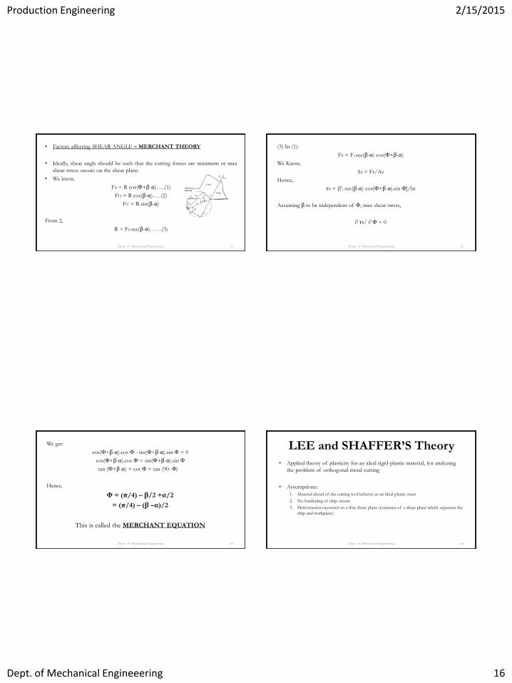
• Factors affecting SHEAR ANGLE – MERCHANT THEORY
• Ideally, shear angle should be such that the cutting forces are minimum or max
shear stress occurs on the shear plane.
• We know,
Fs = R cos(Φ+β-α)…..(1)
FH = R cos(β-α)…..(2)
FV = R sin(β-α)
From 2,
R = FH sec(β-α)……(3)
Dept. of Mechanical Engineering 61
(3) In (1):
Fs = FH sec(β-α) cos(Φ+β-α)
We Know,
τs = Fs/As
Hence,
τs = [FH sec(β-α) cos(Φ+β-α).sin Φ]/bt
Assuming β to be independent of Φ, max shear stress,
∂ τs/ ∂ Φ = 0
Dept. of Mechanical Engineering 62
We get:
cos(Φ+β-α).cos Φ - sin(Φ+β-α).sin Φ = 0
cos(Φ+β-α).cos Φ = sin(Φ+β-α).sin Φ
tan (Φ+β-α) = cot Φ = tan (90- Φ)
Hence,
Φ = (π/4) – β/2 +α/2
= (π/4) – (β –α)/2
This is called the MERCHANT EQUATION
Dept. of Mechanical Engineering 63
LEE and SHAFFER’S Theory
• Applied theory of plasticity for an ideal rigid-plastic material, for analyzing
the problem of orthogonal metal cutting
• Assumptions:
1. Material ahead of the cutting tool behaves as an ideal plastic mass
2. No hardening of chip occurs
3. Deformation occurred on a thin shear plane (existence of a shear plane which separates the
chip and workpiece)
Dept. of Mechanical Engineering 64

Production Engineering 2/15/2015
Dept. of Mechanical Engineeering 17
• Accordingly,
– Metal bounded by triangle ABC is assumed to be rigid plastic, and have been stressed
throughout to its yield point.
– Chip above BC is assumed to be stress free
– Shearing occurs along the slip line BA
– Since chip is assumed to be stress free, the normal stress at BC along the stress free interface
is zero.
• For these conditions, it can be shown that
Φ = (π/4) – (β –α)
Not accurate for most metals.
Dept. of Mechanical Engineering 65
METAL CUTTING PROCESS/PERFORMANCE
PARAMETERS
• The different factors that affect the metal cutting operation are:
1. Velocity (speed rate, feed rate): Affects temp at tool point.
2. Size/Depth of cut
3. Tool geometry
4. Tool material
5. Nature of work-material: Ductile or Brittle
6. Cutting fluids
Dept. of Mechanical Engineering 66
CUTTING POWER (Pc)
• It is the rate at which energy is consumed
Pc = FH. V
Where,
FH = cutting force/horizontal force
V = cutting velocity (tool vel. w.r.t. workpiece)
Dept. of Mechanical Engineering 67
V = [πDN/(60 x 1000)] m/s
Where,
D = diameter of the job/tool in mm
N = Velocity of the job/tool in rpm
If FH is in N and V in m/sec
Pc = FH.V/ 1000 kW
Dept. of Mechanical Engineering 68
Production Engineering 2/15/2015
Dept. of Mechanical Engineeering 18
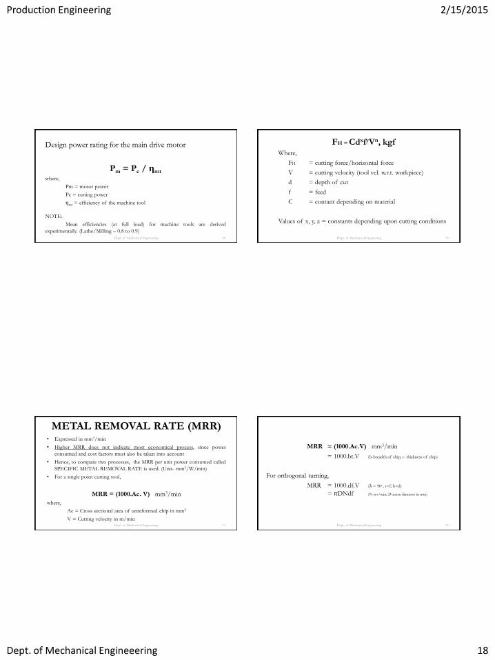
Design power rating for the main drive motor
Pm = Pc / ηmt where,
Pm = motor power
Pc = cutting power
ηmt = efficiency of the machine tool
NOTE:
Mean efficiencies (at full load) for machine tools are derived
experimentally. (Lathe/Milling – 0.8 to 0.9)
Dept. of Mechanical Engineering 69
FH = CdxfyVn, kgf
Where,
FH = cutting force/horizontal force
V = cutting velocity (tool vel. w.r.t. workpiece)
d = depth of cut
f = feed
C = contant depending on material
Values of x, y, z = constants depending upon cutting conditions
Dept. of Mechanical Engineering 70
METAL REMOVAL RATE (MRR) • Expressed in mm3/min
• Higher MRR does not indicate most economical process, since power
consumed and cost factors must also be taken into account
• Hence, to compare two processes, the MRR per unit power consumed called
SPECIFIC METAL REMOVAL RATE is used. (Unit- mm3/W/min)
• For a single point cutting tool,
MRR = (1000.Ac. V) mm3/min
where,
Ac = Cross sectional area of unreformed chip in mm2
V = Cutting velocity in m/min
Dept. of Mechanical Engineering 71
MRR = (1000.Ac.V) mm3/min
= 1000.bt.V (b-breadth of chip, t- thickness of chip)
For orthogonal turning,
MRR = 1000.df.V (λ = 90o, t=f; b=d)
= πDNdf (N-rev/min; D-mean diameter in mm)
Dept. of Mechanical Engineering 72
Production Engineering 2/15/2015
Dept. of Mechanical Engineeering 19
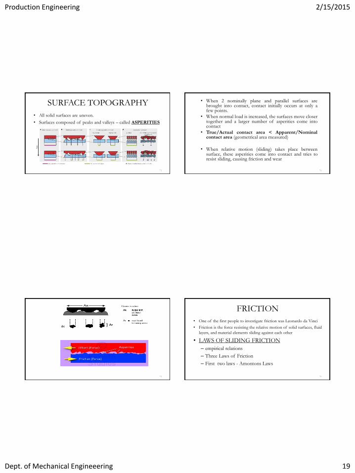
SURFACE TOPOGRAPHY
• All solid surfaces are uneven.
• Surfaces composed of peaks and valleys – called ASPERITIES
73
• When 2 nominally plane and parallel surfaces are brought into contact, contact initially occurs at only a few points.
• When normal load is increased, the surfaces move closer together and a larger number of asperities come into contact
• True/Actual contact area < Apparent/Nominal contact area (geometrical area measured)
• When relative motion (sliding) takes place between surface, these asperities come into contact and tries to resist sliding, causing friction and wear
74
75
FRICTION
• One of the first people to investigate friction was Leonardo da Vinci
• Friction is the force resisting the relative motion of solid surfaces, fluid
layers, and material elements sliding against each other
• LAWS OF SLIDING FRICTION
– empirical relations
– Three Laws of Friction
– First two laws - Amontons Laws
76

Production Engineering 2/15/2015
Dept. of Mechanical Engineeering 20
First Law:
• The frictional force (Ff) is proportional to the normal load (N)
• µ is independent of normal load N
• Mathematically,
• Where,
– Ff – frictional force
– N – total normal reaction/load at contact interface
– µ - coefficient of friction
77 78
• Value of µ varies from 0.001 (lightly loaded rolling
bearing) to greater than 10 (clean metals sliding against
themselves in vacuum)
• Most common materials, µ ranges from 0.1 to 1.
• NOTE: Polymers do not usually obey first law.
79
• Second Law
– Frictional force is independent of the apparent area of
contact
– Experiment – Normal load, held constant, apparent
area of contact increased
– µ is independent of apparent are of contact
– NOTE: Second law – not obeyed by POLYMERS
80
Production Engineering 2/15/2015
Dept. of Mechanical Engineeering 21
• Third Law (Coulomb’s Law)
• Found by Coulomb
– Friction is independent of sliding velocity
– Friction Force to initiate sliding more than that
necessary to maintain it.
– Hence,
• µs (coefficient of static friction) > µd (coefficient of dynamic friction)
• µd is nearly independent of sliding velocity
• At very high speeds (tens or hundreds of m/s), µd falls with
increasing velocity
81
Coefficient of Friction (µ)
• Independent of:
– Normal Force
– Apparent Area of contact
– Nearly independent of sliding velocity
• Depends solely on the materials of the surfaces in
contact.
82
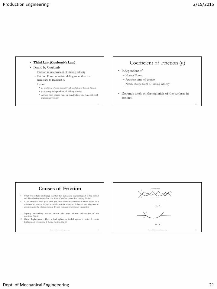
Causes of Friction
• When two surfaces are loaded together they can adhere over some part of the contact
and this adhesion is therefore one form of surface interaction causing friction.
• If no adhesion takes place then the only alternative interaction which results in a
resistance to motion is one in which material must be deformed and displaced to
accommodate the relative motion. We can consider two types of interaction
1. Asperity interlocking: motion cannot take place without deformation of the
asperities (fig A)
2. Macro displacement : Here a hard sphere A loaded against a softer B causes
displacement of material B during motion. (fig B)
Dept. of Mechanical Engineering 83 Dept. of Mechanical Engineering 84
FIG A
FIG B
Production Engineering 2/15/2015
Dept. of Mechanical Engineeering 22
ADHESION THEORY OF FRICTION • Bowden and Tabor explained the adhesion theory of friction when metal surfaces are loaded
against each other, they make contact only at the tips of the asperities.
• Because the real contact area is small the pressure over the contacting asperities is assumed high
enough to cause them to deform plastically.
• This plastic flow of the contacts causes an increase in the area of contact until the real area of
contact is just sufficient to support the load. Under these conditions for on ideal elastic-plastic
material
W = A . Po
• Where A is the real area of contact and Po is the yield pressure of the metal and W is the normal
load.
• When the metals are in contact, cold welding takes place due to adhesion. So a force S per unit
area of contact necessary to shear the junction
Dept. of Mechanical Engineering 85
F = A.S + Pe
• Where Pe is the force required to plough hard asperities through a softer surface. For most
situations involving un-lubricated metals Pe is small compared to AS and may be neglected.
• Therefore, F = AS
F = (W/ Po) . S
F/W = S/ Po
• Therefore µ = F/W = S/ Po
• Thus this theory explains two laws of friction
Dept. of Mechanical Engineering 86
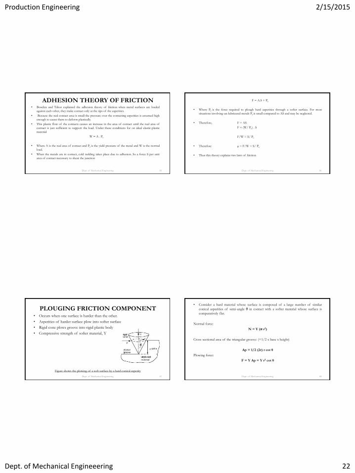
PLOUGING FRICTION COMPONENT • Occurs when one surface is harder than the other.
• Asperities of harder surface plow into softer surface
• Rigid cone plows groove into rigid plastic body
• Compressive strength of softer material, Y
Figure shows the plowing of a soft surface by a hard conical asperity
Dept. of Mechanical Engineering 87
• Consider a hard material whose surface is composed of a large number of similar
conical asperities of semi-angle θ in contact with a softer material whose surface is
comparatively flat.
Normal force:
N = Y (π r2)
Cross sectional area of the triangular groove: (=1/2 x base x height)
Ap = 1/2 (2r) r cot θ
Plowing force:
F = Y Ap = Y r2 cot θ
Dept. of Mechanical Engineering 88
Production Engineering 2/15/2015
Dept. of Mechanical Engineeering 23
Coefficient of friction, plowing:
μp = F/N= cot θ/π
Dept. of Mechanical Engineering 89
Related Documents