PLX3x Series Multi-Protocol Gateways July 28, 2021 USER MANUAL

Welcome message from author
This document is posted to help you gain knowledge. Please leave a comment to let me know what you think about it! Share it to your friends and learn new things together.
Transcript
PLX3x Series Multi-Protocol Gateways
July 28, 2021
USER MANUAL

Your Feedback Please
We always want you to feel that you made the right decision to use our products. If you have suggestions, comments, compliments or complaints about our products, documentation, or support, please write or call us.
How to Contact Us
ProSoft Technology, Inc.
+1 (661) 716-5100 +1 (661) 716-5101 (Fax) www.prosoft-technology.com [email protected]
PLX3x Series User Manual
July 28, 2021
ProSoft Technology®, is a registered copyright of ProSoft Technology, Inc. All other brand or product names are or may be trademarks of, and are used to identify products and services of, their respective owners.
In an effort to conserve paper, ProSoft Technology no longer includes printed manuals with our product shipments. User Manuals, Datasheets, Sample Ladder Files, and Configuration Files are provided at our website: http://www.prosoft-technology.com
Content Disclaimer
This documentation is not intended as a substitute for and is not to be used for determining suitability or reliability of these products for specific user applications. It is the duty of any such user or integrator to perform the appropriate and complete risk analysis, evaluation and testing of the products with respect to the relevant specific application or use thereof. Neither ProSoft Technology nor any of its affiliates or subsidiaries shall be responsible or liable for misuse of the information contained herein. Information in this document including illustrations, specifications and dimensions may contain technical inaccuracies or typographical errors. ProSoft Technology makes no warranty or representation as to its accuracy and assumes no liability for and reserves the right to correct such inaccuracies or errors at any time without notice. If you have any suggestions for improvements or amendments or have found errors in this publication, please notify us.
No part of this document may be reproduced in any form or by any means, electronic or mechanical, including photocopying, without express written permission of ProSoft Technology. All pertinent state, regional, and local safety regulations must be observed when installing and using this product. For reasons of safety and to help ensure compliance with documented system data, only the manufacturer should perform repairs to components. When devices are used for applications with technical safety requirements, the relevant instructions must be followed. Failure to use ProSoft Technology software or approved software with our hardware products may result in injury, harm, or improper operating results. Failure to observe this information can result in injury or equipment damage.
Copyright © 2021 ProSoft Technology, Inc. All Rights Reserved.
Printed documentation is available for purchase. Contact ProSoft Technology for pricing and availability.
North America: +1 (661) 716-5100 Asia Pacific: +603.7724.2080 Europe, Middle East, Africa: +33 (0) 5.3436.87.20 Latin America: +1.281.298.9109

Open Source Information
Open Source Software used in the product
The product contains, among other things, Open Source Software files, as defined below, developed by third parties and licensed under an Open Source Software license. These Open Source Software files are protected by copyright. Your right to use the Open Source Software is governed by the relevant applicable Open Source Software license conditions. Your compliance with those license conditions will entitle you to use the Open Source Software as foreseen in the relevant license. In the event of conflicts between other ProSoft Technology, Inc. license conditions applicable to the product and the Open Source Software license conditions, the Open Source Software conditions shall prevail. The Open Source Software is provided royalty-free (i.e. no fees are charged for exercising the licensed rights). Open Source Software contained in this product and the respective Open Source Software licenses are stated in the module webpage, in the link Open Source.
If Open Source Software contained in this product is licensed under GNU General Public License (GPL), GNU Lesser General Public License (LGPL), Mozilla Public License (MPL) or any other Open Source Software license, which requires that source code is to be made available and such source code is not already delivered together with the product, you can order the corresponding source code of the Open Source Software from ProSoft Technology, Inc. - against payment of the shipping and handling charges - for a period of at least 3 years since purchase of the product. Please send your specific request, within 3 years of the purchase date of this product, together with the name and serial number of the product found on the product label to:
ProSoft Technology, Inc. Director of Engineering 9201 Camino Media, Suite 200 Bakersfield, CA 93311 USA
Warranty regarding further use of the Open Source Software
ProSoft Technology, Inc. provides no warranty for the Open Source Software contained in this product, if such Open Source Software is used in any manner other than intended by ProSoft Technology, Inc. The licenses listed below define the warranty, if any, from the authors or licensors of the Open Source Software. ProSoft Technology, Inc. specifically disclaims any warranty for defects caused by altering any Open Source Software or the product’s configuration. Any warranty claims against ProSoft Technology, Inc. in the event that the Open Source Software contained in this product infringes the intellectual property rights of a third party are excluded. The following disclaimer applies to the GPL and LGPL components in relation to the rights holders:
“This program is distributed in the hope that it will be useful, but WITHOUT ANY WARRANTY; without even the implied warranty of MERCHANTABILITY or FITNESS FOR A PARTICULAR PURPOSE. See the GNU General Public License and the GNU Lesser General Public License for more details.”
For the remaining open source components, the liability exclusions of the rights holders in the respective license texts apply. Technical support, if any, will only be provided for unmodified software.
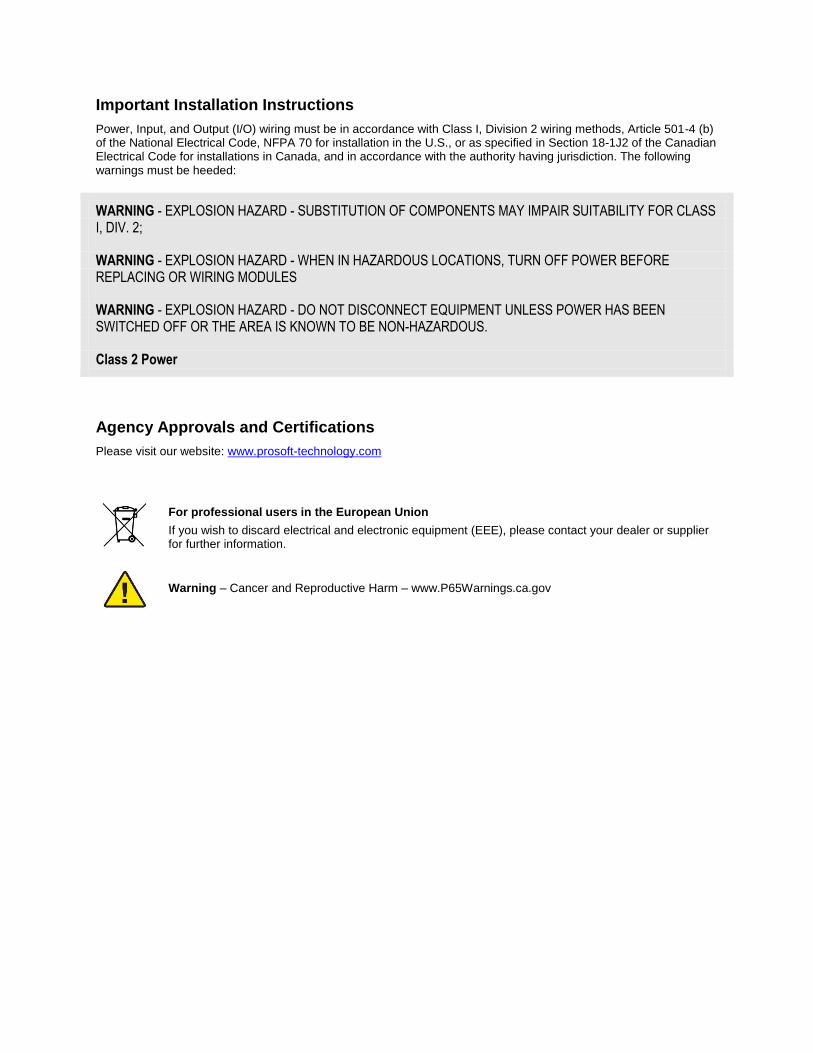
Important Installation Instructions
Power, Input, and Output (I/O) wiring must be in accordance with Class I, Division 2 wiring methods, Article 501-4 (b) of the National Electrical Code, NFPA 70 for installation in the U.S., or as specified in Section 18-1J2 of the Canadian Electrical Code for installations in Canada, and in accordance with the authority having jurisdiction. The following warnings must be heeded:
WARNING - EXPLOSION HAZARD - SUBSTITUTION OF COMPONENTS MAY IMPAIR SUITABILITY FOR CLASS I, DIV. 2;
WARNING - EXPLOSION HAZARD - WHEN IN HAZARDOUS LOCATIONS, TURN OFF POWER BEFORE REPLACING OR WIRING MODULES
WARNING - EXPLOSION HAZARD - DO NOT DISCONNECT EQUIPMENT UNLESS POWER HAS BEEN SWITCHED OFF OR THE AREA IS KNOWN TO BE NON-HAZARDOUS.
Class 2 Power
Agency Approvals and Certifications
Please visit our website: www.prosoft-technology.com
For professional users in the European Union
If you wish to discard electrical and electronic equipment (EEE), please contact your dealer or supplier for further information.
Warning – Cancer and Reproductive Harm – www.P65Warnings.ca.gov
PLX3x Series ♦ Multi-Protocol Gateways Contents User Manual
ProSoft Technology, Inc. Page 5 of 198
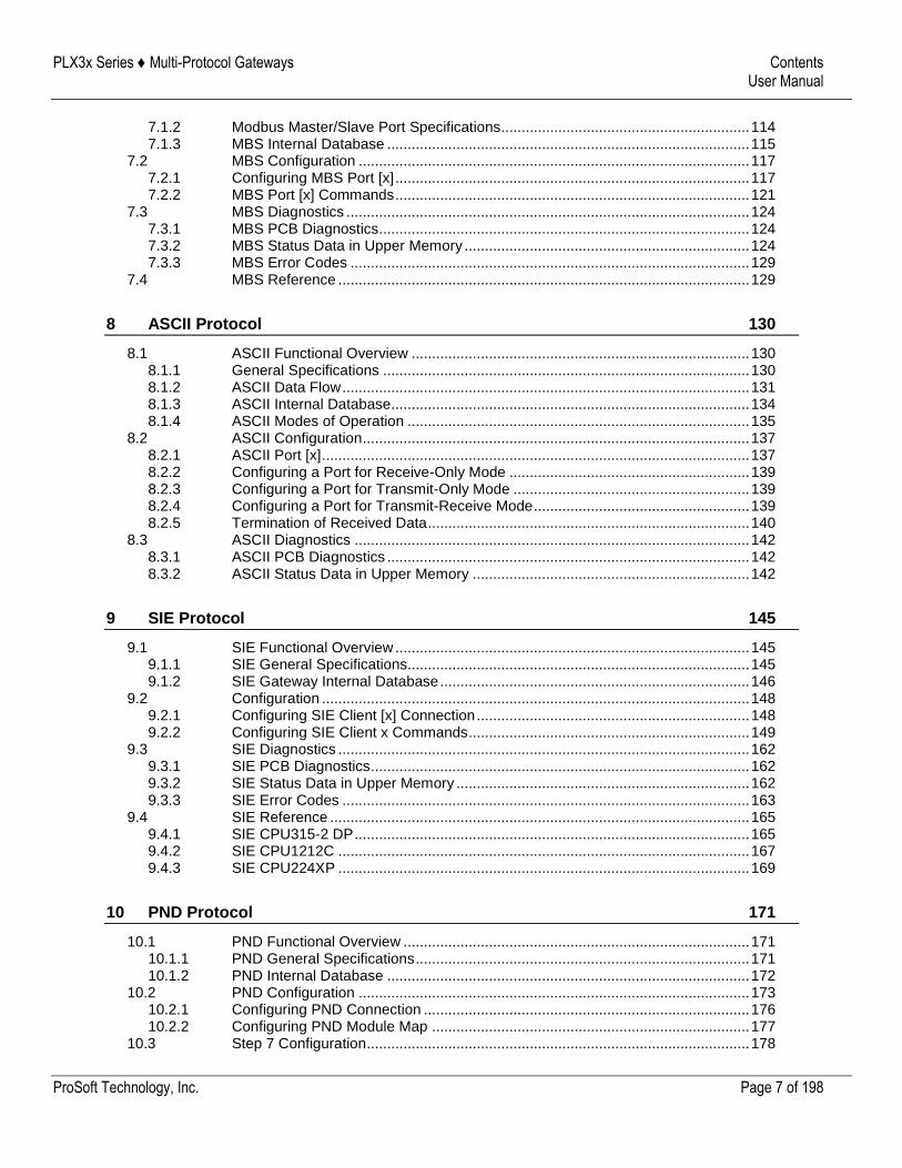
Contents
Your Feedback Please ........................................................................................................................ 2 How to Contact Us .............................................................................................................................. 2 Content Disclaimer .............................................................................................................................. 2 Open Source Information .................................................................................................................... 3 Important Installation Instructions ....................................................................................................... 4 Agency Approvals and Certifications .................................................................................................. 4
1 Start Here 9
1.1 Overview.................................................................................................................... 9 1.2 System Requirements ............................................................................................... 9 1.3 Package Contents ................................................................................................... 10 1.4 Mounting the Gateway on a DIN-rail ....................................................................... 11 1.5 Jumper Settings ...................................................................................................... 12 1.6 SD Card ................................................................................................................... 13 1.7 Connecting Power to the Unit ................................................................................. 13 1.8 Installing ProSoft Configuration Builder Software ................................................... 14
2 Using ProSoft Configuration Builder 15
2.1 Connecting the PC to the Gateway ......................................................................... 15 2.2 Setting a Temporary IP Address in the Gateway .................................................... 15 2.3 Setting Up the Project ............................................................................................. 18 2.4 Disabling Gateway Ports ......................................................................................... 20 2.5 Configuring Gateway Parameters ........................................................................... 23
2.5.1 Renaming PCB Objects .......................................................................................... 23 2.5.2 Printing a Configuration File .................................................................................... 23
2.6 Configuring the Ethernet Port .................................................................................. 24 2.7 Mapping Data in Module Memory ........................................................................... 25
2.7.1 From Address .......................................................................................................... 26 2.7.2 To Address .............................................................................................................. 26 2.7.3 Register Count ........................................................................................................ 26 2.7.4 Swap Code .............................................................................................................. 27 2.7.5 Delay Preset ............................................................................................................ 27
2.8 Downloading the Project to the Gateway ................................................................ 28 2.9 Uploading the Project from the Gateway ................................................................ 30
3 Diagnostics and Troubleshooting 32
3.1 LED Indicators ......................................................................................................... 32 3.1.1 Main Gateway LEDs ................................................................................................ 33 3.1.2 Ethernet Port LEDs ................................................................................................. 34 3.1.3 Serial Port LEDs (for Gateways with Serial Ports) .................................................. 34
3.2 Using Diagnostics in ProSoft Configuration Builder ................................................ 35 3.2.1 Diagnostics Menu .................................................................................................... 37 3.2.2 Capturing a Diagnostic Session to a Log File ......................................................... 38 3.2.3 Using the Data Analyzer (Serial Protocols Only) .................................................... 39 3.2.4 Warm Boot / Cold Boot ............................................................................................ 40
3.3 Gateway Status Data in Upper Memory .................................................................. 41 3.3.1 General Gateway Status Data in Upper Memory .................................................... 41
PLX3x Series ♦ Multi-Protocol Gateways Contents User Manual
ProSoft Technology, Inc. Page 6 of 198
3.3.2 Protocol-Specific Status Data in Upper Memory ..................................................... 42
4 Hardware Information 43
4.1 Hardware Specifications.......................................................................................... 43 4.1.1 Serial Port Specifications ........................................................................................ 44
4.2 Serial Port Cables (for Gateways with Serial Ports) ............................................... 44 4.2.1 DB9 to RJ45 Adaptor (Cable 14) ............................................................................ 45 4.2.2 Serial Port Specifications ........................................................................................ 45 4.2.3 RS-232 - Null Modem (DTE without Hardware Handshaking) ................................ 46 4.2.4 RS-232 - DTE to DCE Modem Connection ............................................................. 46 4.2.5 RS-422 Interface Connections ................................................................................ 47 4.2.6 RS-485 Interface Connection .................................................................................. 47
5 EIP Protocol 48
5.1 EIP Functional Overview ......................................................................................... 48 5.1.1 EtherNet/IP General Specifications ......................................................................... 48 5.1.2 EIP Internal Database ............................................................................................. 49
5.2 EIP Configuration .................................................................................................... 51 5.2.1 Configuring EIP Class 3 Server .............................................................................. 51 5.2.2 Configuring EIP Class 1 Connection ....................................................................... 54 5.2.3 Configuring EIP Class 3 Client[x]/UClient Connection ............................................ 59
5.3 Network Diagnostics ................................................................................................ 69 5.3.1 EIP PCB Diagnostics ............................................................................................... 69 5.3.2 EIP Status Data in Upper Memory .......................................................................... 70 5.3.3 EIP Error Codes ...................................................................................................... 72
5.4 EIP Reference ......................................................................................................... 76 5.4.1 SLC and MicroLogix Specifics ................................................................................ 76 5.4.2 PLC5 Processor Specifics ....................................................................................... 80 5.4.3 ControlLogix and CompactLogix Processor Specifics ............................................ 85
6 MBTCP Protocol 94
6.1 MBTCP Functional Overview .................................................................................. 94 6.1.1 MBTCP General Specifications ............................................................................... 95 6.1.2 MBTCP Internal Database ...................................................................................... 96
6.2 MBTCP Configuration ............................................................................................. 99 6.2.1 Configuring MBTCP Servers ................................................................................... 99 6.2.2 Pass Through Feature ........................................................................................... 101 6.2.3 Configuring MBTCP Client [x] ............................................................................... 102 6.2.4 Configuring MBTCP Client [x] Commands ............................................................ 104
6.3 Network Diagnostics .............................................................................................. 107 6.3.1 MBTCP PCB Diagnostics ...................................................................................... 107 6.3.2 MBTCP Status Data in Upper Memory ................................................................. 108 6.3.3 MBTCP Error Codes ............................................................................................. 111
6.4 MBTCP Reference ................................................................................................ 112 6.4.1 About the Modbus Protocol ................................................................................... 112
7 MBS Protocol 113
7.1 MBS Functional Overview ..................................................................................... 113 7.1.1 Modbus Serial Specifications ................................................................................ 113
PLX3x Series ♦ Multi-Protocol Gateways Contents User Manual
ProSoft Technology, Inc. Page 7 of 198
7.1.2 Modbus Master/Slave Port Specifications ............................................................. 114 7.1.3 MBS Internal Database ......................................................................................... 115
7.2 MBS Configuration ................................................................................................ 117 7.2.1 Configuring MBS Port [x] ....................................................................................... 117 7.2.2 MBS Port [x] Commands ....................................................................................... 121
7.3 MBS Diagnostics ................................................................................................... 124 7.3.1 MBS PCB Diagnostics ........................................................................................... 124 7.3.2 MBS Status Data in Upper Memory ...................................................................... 124 7.3.3 MBS Error Codes .................................................................................................. 129
7.4 MBS Reference ..................................................................................................... 129
8 ASCII Protocol 130
8.1 ASCII Functional Overview ................................................................................... 130 8.1.1 General Specifications .......................................................................................... 130 8.1.2 ASCII Data Flow .................................................................................................... 131 8.1.3 ASCII Internal Database........................................................................................ 134 8.1.4 ASCII Modes of Operation .................................................................................... 135
8.2 ASCII Configuration ............................................................................................... 137 8.2.1 ASCII Port [x] ......................................................................................................... 137 8.2.2 Configuring a Port for Receive-Only Mode ........................................................... 139 8.2.3 Configuring a Port for Transmit-Only Mode .......................................................... 139 8.2.4 Configuring a Port for Transmit-Receive Mode ..................................................... 139 8.2.5 Termination of Received Data ............................................................................... 140
8.3 ASCII Diagnostics ................................................................................................. 142 8.3.1 ASCII PCB Diagnostics ......................................................................................... 142 8.3.2 ASCII Status Data in Upper Memory .................................................................... 142
9 SIE Protocol 145
9.1 SIE Functional Overview ....................................................................................... 145 9.1.1 SIE General Specifications.................................................................................... 145 9.1.2 SIE Gateway Internal Database ............................................................................ 146
9.2 Configuration ......................................................................................................... 148 9.2.1 Configuring SIE Client [x] Connection ................................................................... 148 9.2.2 Configuring SIE Client x Commands ..................................................................... 149
9.3 SIE Diagnostics ..................................................................................................... 162 9.3.1 SIE PCB Diagnostics ............................................................................................. 162 9.3.2 SIE Status Data in Upper Memory ........................................................................ 162 9.3.3 SIE Error Codes .................................................................................................... 163
9.4 SIE Reference ....................................................................................................... 165 9.4.1 SIE CPU315-2 DP ................................................................................................. 165 9.4.2 SIE CPU1212C ..................................................................................................... 167 9.4.3 SIE CPU224XP ..................................................................................................... 169
10 PND Protocol 171
10.1 PND Functional Overview ..................................................................................... 171 10.1.1 PND General Specifications .................................................................................. 171 10.1.2 PND Internal Database ......................................................................................... 172
10.2 PND Configuration ................................................................................................ 173 10.2.1 Configuring PND Connection ................................................................................ 176 10.2.2 Configuring PND Module Map .............................................................................. 177
10.3 Step 7 Configuration .............................................................................................. 178
PLX3x Series ♦ Multi-Protocol Gateways Contents User Manual
ProSoft Technology, Inc. Page 8 of 198
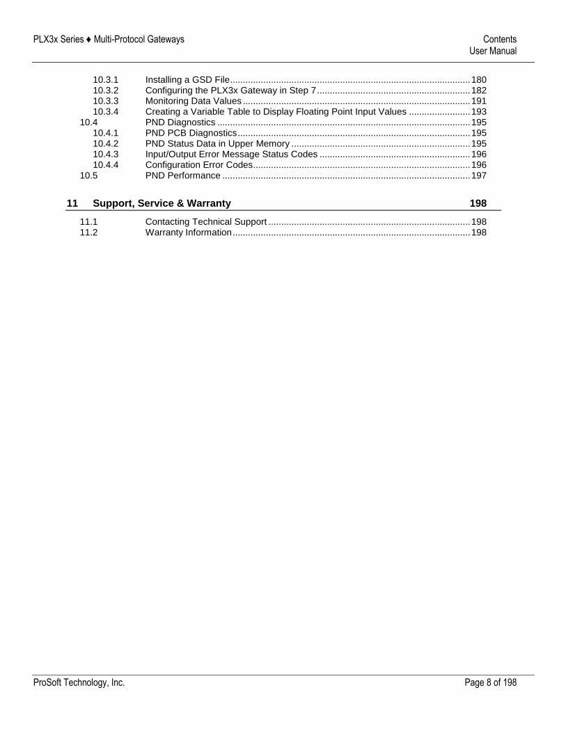
10.3.1 Installing a GSD File .............................................................................................. 180 10.3.2 Configuring the PLX3x Gateway in Step 7 ............................................................ 182 10.3.3 Monitoring Data Values ......................................................................................... 191 10.3.4 Creating a Variable Table to Display Floating Point Input Values ........................ 193
10.4 PND Diagnostics ................................................................................................... 195 10.4.1 PND PCB Diagnostics ........................................................................................... 195 10.4.2 PND Status Data in Upper Memory ...................................................................... 195 10.4.3 Input/Output Error Message Status Codes ........................................................... 196 10.4.4 Configuration Error Codes..................................................................................... 196
10.5 PND Performance ................................................................................................. 197
11 Support, Service & Warranty 198
11.1 Contacting Technical Support ............................................................................... 198 11.2 Warranty Information ............................................................................................. 198
PLX3x Series ♦ Multi-Protocol Gateways Start Here User Manual
ProSoft Technology, Inc. Page 9 of 198
1 Start Here
To get the most benefit from this User Manual, you should have the following skills:
PLC or PAC configuration software: Launch the program and use it to configure the processor if required
Microsoft Windows®: Install and launch programs, execute menu commands, navigate dialog boxes, and enter data
Hardware installation and wiring: Install the module, and safely connect devices to a power source and to the PLX3x gateway port(s)
1.1 Overview
This document explains the features of the PLX3x gateway. It guides you through configuration, showing how to map data between a device or network, through the gateway, to a PLC or PAC. The ProSoft Configuration Builder software creates files to import into the PLC or PAC programming software, integrating the gateway into your system. You can also map data between areas in the gateway's internal database. This allows you to copy data to different addresses within the gateway database in order to create easier data requests and control.
The PLX3x gateways are stand-alone DIN-rail mounted units that provide one Ethernet port for communications, remote configuration, and diagnostics. Your specific gateway may include additional ports depending on the supported protocols. The module has an SD Card slot (SD card optional) that allows you to store configuration files that you can use for recovery, transferring the configuration to another gateway, or general configuration backup.
1.2 System Requirements
The ProSoft Configuration Builder configuration software for the PLX3x gateway requires the following minimum hardware and software components:
Pentium® II 450 MHz minimum. Pentium III 733 MHz (or better) recommended
128 Mbytes of RAM minimum, 256 Mbytes of RAM recommended
100 Mbytes of free hard disk space (or more based on application requirements)
256-color VGA graphics adapter, 800 x 600 minimum resolution (True Color 1024 768 recommended)
Supported operating systems:
Microsoft Windows 10 (64 bit)
Microsoft Windows 7 (32/64 bit)
Microsoft Windows XP Professional with Service Pack 1 or 2
Microsoft Windows 2000 Professional with Service Pack 1, 2, or 3 (not tested)
Microsoft Windows Server 2003 (not tested)
PLX3x Series ♦ Multi-Protocol Gateways Start Here User Manual
ProSoft Technology, Inc. Page 10 of 198
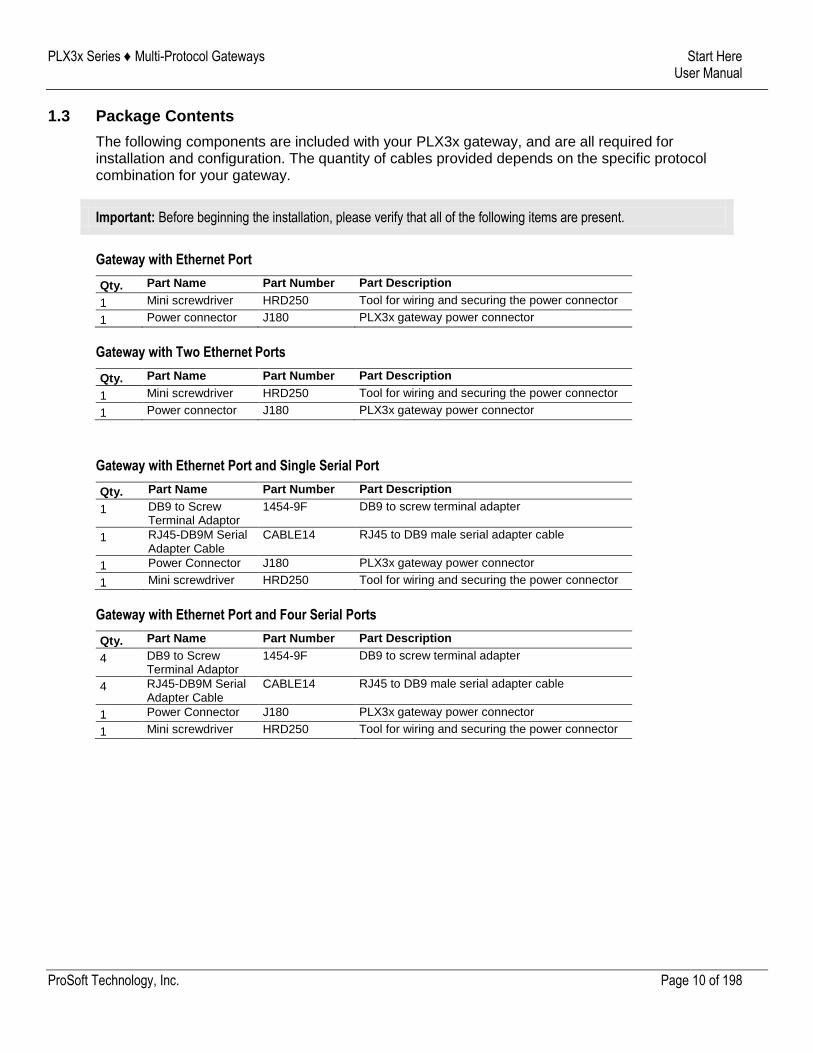
1.3 Package Contents
The following components are included with your PLX3x gateway, and are all required for installation and configuration. The quantity of cables provided depends on the specific protocol combination for your gateway.
Important: Before beginning the installation, please verify that all of the following items are present.
Gateway with Ethernet Port
Qty. Part Name Part Number Part Description
1 Mini screwdriver HRD250 Tool for wiring and securing the power connector
1 Power connector J180 PLX3x gateway power connector
Gateway with Two Ethernet Ports
Qty. Part Name Part Number Part Description
1 Mini screwdriver HRD250 Tool for wiring and securing the power connector
1 Power connector J180 PLX3x gateway power connector
Gateway with Ethernet Port and Single Serial Port
Qty. Part Name Part Number Part Description
1 DB9 to Screw Terminal Adaptor
1454-9F DB9 to screw terminal adapter
1 RJ45-DB9M Serial Adapter Cable
CABLE14 RJ45 to DB9 male serial adapter cable
1 Power Connector J180 PLX3x gateway power connector
1 Mini screwdriver HRD250 Tool for wiring and securing the power connector
Gateway with Ethernet Port and Four Serial Ports
Qty. Part Name Part Number Part Description
4 DB9 to Screw Terminal Adaptor
1454-9F DB9 to screw terminal adapter
4 RJ45-DB9M Serial Adapter Cable
CABLE14 RJ45 to DB9 male serial adapter cable
1 Power Connector J180 PLX3x gateway power connector
1 Mini screwdriver HRD250 Tool for wiring and securing the power connector
PLX3x Series ♦ Multi-Protocol Gateways Start Here User Manual
ProSoft Technology, Inc. Page 11 of 198
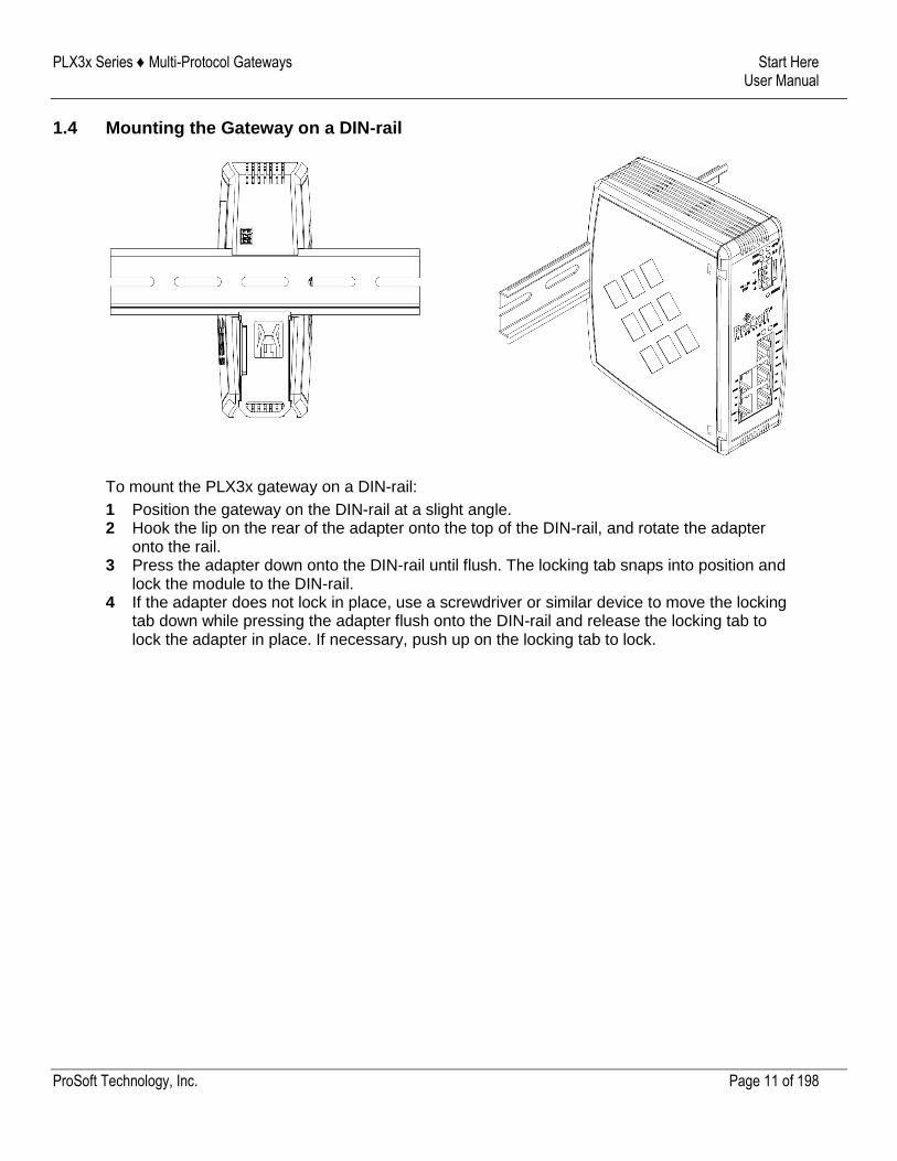
1.4 Mounting the Gateway on a DIN-rail
To mount the PLX3x gateway on a DIN-rail:
1 Position the gateway on the DIN-rail at a slight angle. 2 Hook the lip on the rear of the adapter onto the top of the DIN-rail, and rotate the adapter
onto the rail. 3 Press the adapter down onto the DIN-rail until flush. The locking tab snaps into position and
lock the module to the DIN-rail. 4 If the adapter does not lock in place, use a screwdriver or similar device to move the locking
tab down while pressing the adapter flush onto the DIN-rail and release the locking tab to lock the adapter in place. If necessary, push up on the locking tab to lock.
PLX3x Series ♦ Multi-Protocol Gateways Start Here User Manual
ProSoft Technology, Inc. Page 12 of 198
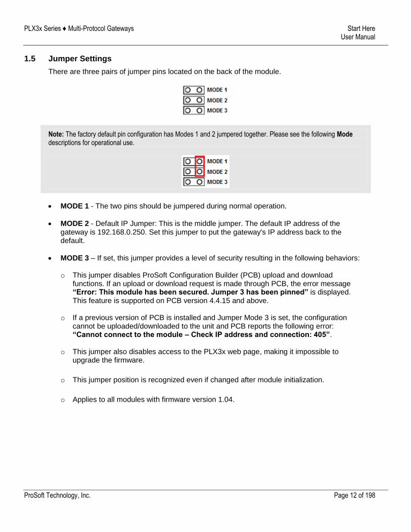
1.5 Jumper Settings
There are three pairs of jumper pins located on the back of the module.
Note: The factory default pin configuration has Modes 1 and 2 jumpered together. Please see the following Mode descriptions for operational use.
MODE 1 - The two pins should be jumpered during normal operation.
MODE 2 - Default IP Jumper: This is the middle jumper. The default IP address of the gateway is 192.168.0.250. Set this jumper to put the gateway's IP address back to the default.
MODE 3 – If set, this jumper provides a level of security resulting in the following behaviors: o This jumper disables ProSoft Configuration Builder (PCB) upload and download
functions. If an upload or download request is made through PCB, the error message “Error: This module has been secured. Jumper 3 has been pinned” is displayed. This feature is supported on PCB version 4.4.15 and above.
o If a previous version of PCB is installed and Jumper Mode 3 is set, the configuration cannot be uploaded/downloaded to the unit and PCB reports the following error: “Cannot connect to the module – Check IP address and connection: 405”.
o This jumper also disables access to the PLX3x web page, making it impossible to upgrade the firmware.
o This jumper position is recognized even if changed after module initialization.
o Applies to all modules with firmware version 1.04.
PLX3x Series ♦ Multi-Protocol Gateways Start Here User Manual
ProSoft Technology, Inc. Page 13 of 198
1.6 SD Card
You can order a PLX3x gateway with an optional SD card (Part Number SDI-1G). In the event of a module failure, you can move the SD card from one module to the next and resume operation.
In general, if the SD card is present when you power up or reboot the module, the module uses the configuration on the SC card.
With an SD Card
PCB downloads the configuration to the SD Card in the module.
The module does not transfer the configuration data from the SD card to internal memory. If you remove the SD card and reboot to the module, the module loads the configuration data from the module’s memory. If there is no configuration data in the module’s memory, the module uses the factory default configuration.
Without an SD Card
PCB downloads the configuration to the module’s internal memory.
If you insert a blank SD Card into the module after the module has been configured, the module does not use the configuration on the SD card unless you reboot the module. If you want to copy the configuration to the SD card, you must download the configuration while the SD card is in the module.
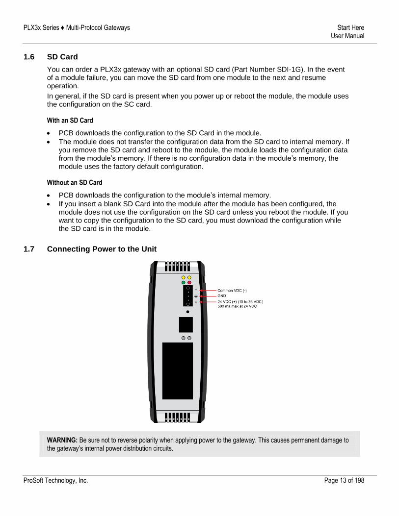
1.7 Connecting Power to the Unit
WARNING: Be sure not to reverse polarity when applying power to the gateway. This causes permanent damage to the gateway’s internal power distribution circuits.
PLX3x Series ♦ Multi-Protocol Gateways Start Here User Manual
ProSoft Technology, Inc. Page 14 of 198
1.8 Installing ProSoft Configuration Builder Software
You must install the ProSoft Configuration Builder (PCB) software to configure the gateway. You can download the newest version of ProSoft Configuration Builder from: www.prosoft-technology.com.
To install ProSoft Configuration Builder from the ProSoft Technology website
1 Open your web browser and navigate to www.prosoft-technology.com. 2 Search for 'PCB' or 'ProSoft Configuration Builder'. 3 Click on the ProSoft Configuration Builder search result link. 4 From the Downloads link, download the latest version of ProSoft Configuration Builder. 5 Choose SAVE or SAVE FILE, if prompted. 6 Save the file to your Windows Desktop, so that you can find it easily when you have finished
downloading. 7 When the download is complete, locate and open the file, and then follow the instructions on
your screen to install the program.
Note: To use the ProSoft Configuration Builder under the Windows 7 OS, you must be sure to install it using the Run as Administrator option. To find this option, right-click the Setup.exe program icon, and then click RUN AS
ADMINISTRATOR on the context menu. You must install using this option even if you are already logged in as an Administrator on your network or personal computer (PC). Using the Run as Administrator option allows the installation program to create folders and files on your PC with proper permissions and security.
If you do not use the Run as Administrator option, the ProSoft Configuration Builder may appear to install correctly, but you will receive multiple file access errors whenever the ProSoft Configuration Builder is running, especially when changing configuration screens. If this happens, you must completely uninstall the ProSoft Configuration Builder and then re-install using the Run as Administrator option to eliminate the errors.
PLX3x Series ♦ Multi-Protocol Gateways Using ProSoft Configuration Builder User Manual
ProSoft Technology, Inc. Page 15 of 198
2 Using ProSoft Configuration Builder
ProSoft Configuration Builder (PCB) provides a quick and easy way to manage gateway configuration files customized to meet your application needs. PCB is not only a powerful solution for new configuration files, but also allows you to import information from previously installed (known working) configurations to new projects.
2.1 Connecting the PC to the Gateway
With the module securely mounted, connect one end of the Ethernet cable to the ETH 1 Port, and the other end to an Ethernet hub or switch accessible from the same network as the PC. Or, connect directly from the Ethernet Port on the PC to the ETH 1 Port on the module.
2.2 Setting a Temporary IP Address in the Gateway
Important: ProSoft Discovery Service (PDS) locates the gateway through UDP broadcast messages. PDS is an application that is built into PCB. These messages may be blocked by routers or layer 3 switches. In that case, PDS is unable to locate the gateways. To use PDS, arrange the Ethernet connection so that there is no router or layer 3 switch between the computer and the gateway OR reconfigure the router or layer 3 switch to allow the routing of the UDP broadcast messages.
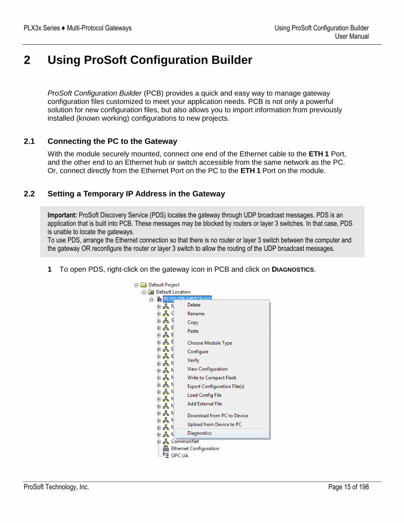
1 To open PDS, right-click on the gateway icon in PCB and click on DIAGNOSTICS.
PLX3x Series ♦ Multi-Protocol Gateways Using ProSoft Configuration Builder User Manual
ProSoft Technology, Inc. Page 16 of 198
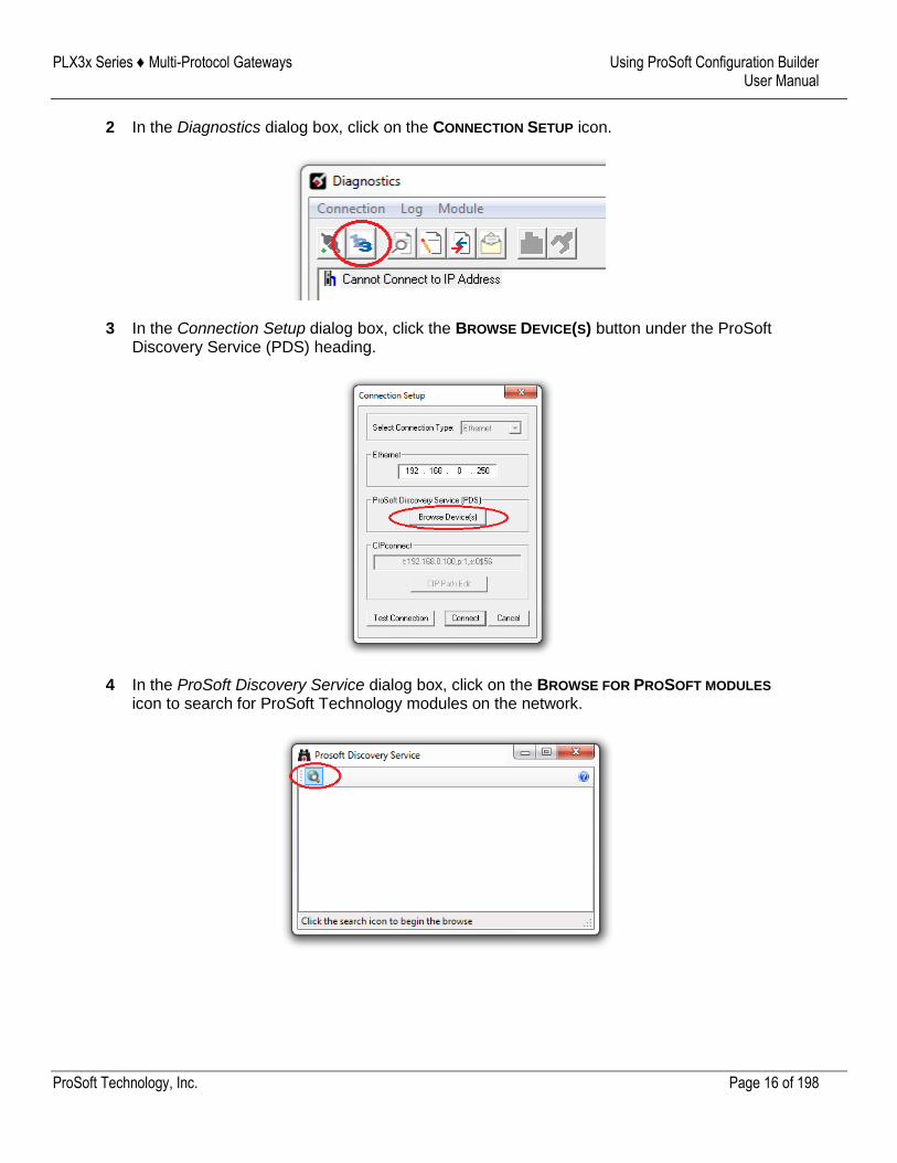
2 In the Diagnostics dialog box, click on the CONNECTION SETUP icon.
3 In the Connection Setup dialog box, click the BROWSE DEVICE(S) button under the ProSoft
Discovery Service (PDS) heading.
4 In the ProSoft Discovery Service dialog box, click on the BROWSE FOR PROSOFT MODULES
icon to search for ProSoft Technology modules on the network.
PLX3x Series ♦ Multi-Protocol Gateways Using ProSoft Configuration Builder User Manual
ProSoft Technology, Inc. Page 17 of 198
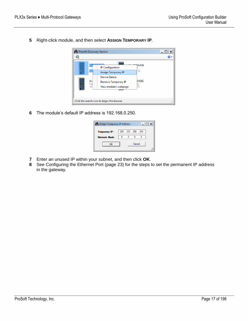
5 Right-click module, and then select ASSIGN TEMPORARY IP.
6 The module’s default IP address is 192.168.0.250.
7 Enter an unused IP within your subnet, and then click OK. 8 See Configuring the Ethernet Port (page 23) for the steps to set the permanent IP address
in the gateway.
PLX3x Series ♦ Multi-Protocol Gateways Using ProSoft Configuration Builder User Manual
ProSoft Technology, Inc. Page 18 of 198
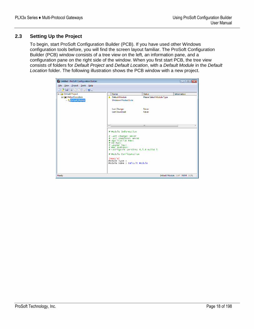
2.3 Setting Up the Project
To begin, start ProSoft Configuration Builder (PCB). If you have used other Windows configuration tools before, you will find the screen layout familiar. The ProSoft Configuration Builder (PCB) window consists of a tree view on the left, an information pane, and a configuration pane on the right side of the window. When you first start PCB, the tree view consists of folders for Default Project and Default Location, with a Default Module in the Default Location folder. The following illustration shows the PCB window with a new project.
PLX3x Series ♦ Multi-Protocol Gateways Using ProSoft Configuration Builder User Manual
ProSoft Technology, Inc. Page 19 of 198
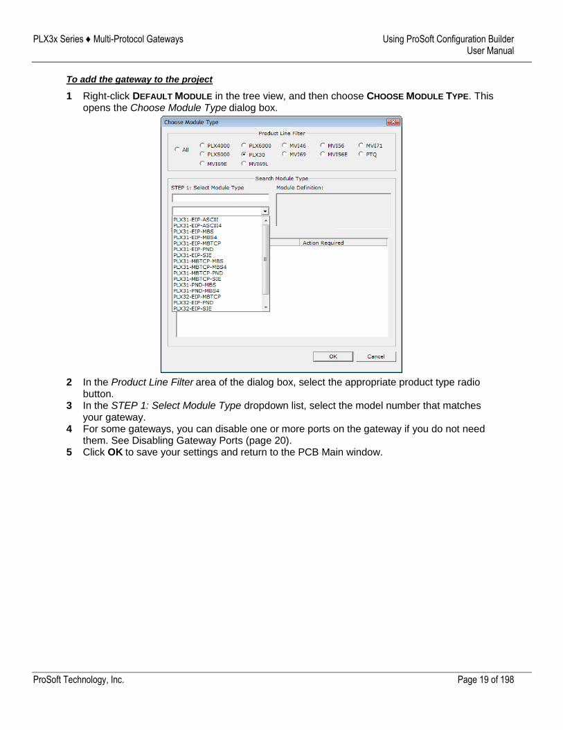
To add the gateway to the project
1 Right-click DEFAULT MODULE in the tree view, and then choose CHOOSE MODULE TYPE. This opens the Choose Module Type dialog box.
2 In the Product Line Filter area of the dialog box, select the appropriate product type radio button.
3 In the STEP 1: Select Module Type dropdown list, select the model number that matches your gateway.
4 For some gateways, you can disable one or more ports on the gateway if you do not need them. See Disabling Gateway Ports (page 20).
5 Click OK to save your settings and return to the PCB Main window.
PLX3x Series ♦ Multi-Protocol Gateways Using ProSoft Configuration Builder User Manual
ProSoft Technology, Inc. Page 20 of 198
2.4 Disabling Gateway Ports
For some gateways, ProSoft Configuration Builder (PCB) gives you the option to disable one or more ports if you do not need them. Disabling ports can simplify the number of configuration options, making it easier to set up the gateway.
It is easiest to disable ports when you add the gateway to the project in PCB; however, you can enable and disable ports after you have added it to the project. Both methods are described in this topic.
Note: Disabling ports does not affect the performance of the gateway and is not required.
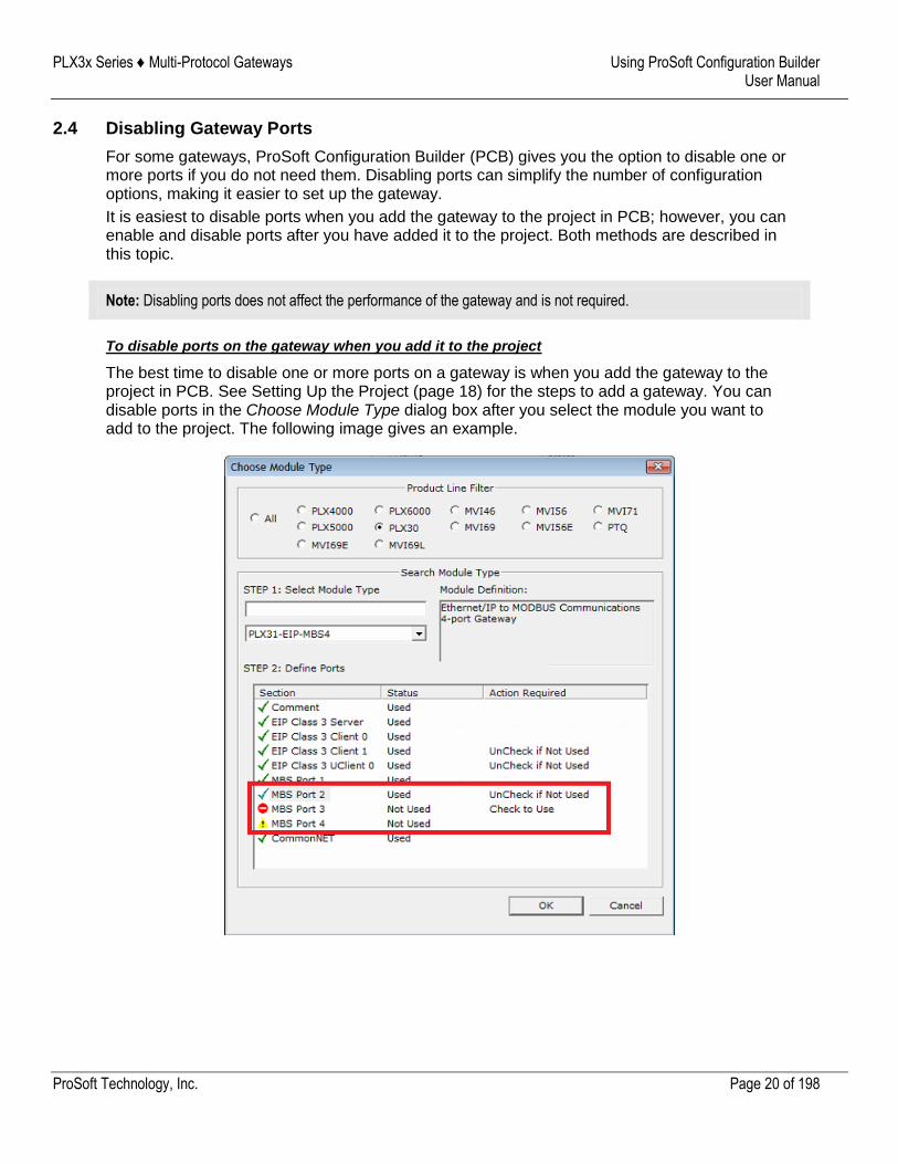
To disable ports on the gateway when you add it to the project
The best time to disable one or more ports on a gateway is when you add the gateway to the project in PCB. See Setting Up the Project (page 18) for the steps to add a gateway. You can disable ports in the Choose Module Type dialog box after you select the module you want to add to the project. The following image gives an example.
PLX3x Series ♦ Multi-Protocol Gateways Using ProSoft Configuration Builder User Manual
ProSoft Technology, Inc. Page 21 of 198
There are two ports disabled. Please note the following:
Ports that you can disable have UNCHECK IF NOT USED in the ACTION REQUIRED column.
Click the port name to disable the port. When you disable a port, a red circle replaces the green checkmark (MBS Port 3 in this example).
If there are multiple ports of the same type, only the last one has the UnCheck if not Used message (MBS Port 2). You can disable and enable ports only in reverse order. In this example, MBS Port 4 was disabled before MBS Port 3.
If you disable multiple ports of the same type, a yellow triangle replaces the red circle for the port(s) that you disabled first (MBS Port 4).
Finally, if you want to enable a disabled port in this dialog box, click the port name again. Remember that you can enable ports only in order. In this example, you must enable MBS Port 3 before you can enable MBS Port 4.
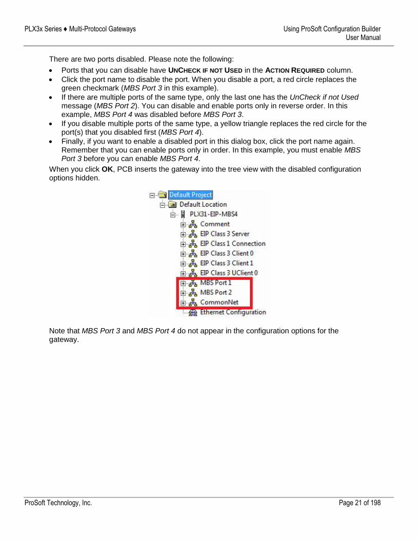
When you click OK, PCB inserts the gateway into the tree view with the disabled configuration options hidden.
Note that MBS Port 3 and MBS Port 4 do not appear in the configuration options for the gateway.
PLX3x Series ♦ Multi-Protocol Gateways Using ProSoft Configuration Builder User Manual
ProSoft Technology, Inc. Page 22 of 198
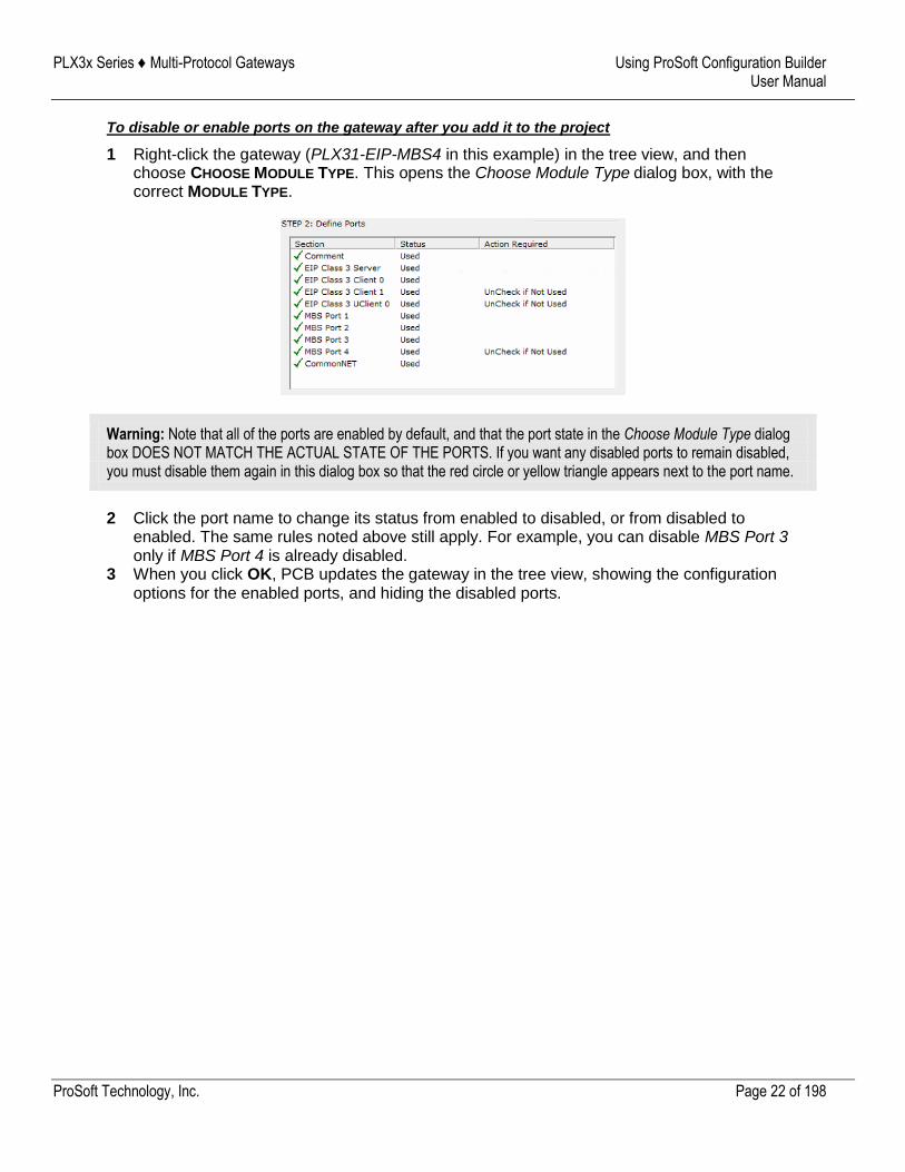
To disable or enable ports on the gateway after you add it to the project
1 Right-click the gateway (PLX31-EIP-MBS4 in this example) in the tree view, and then choose CHOOSE MODULE TYPE. This opens the Choose Module Type dialog box, with the correct MODULE TYPE.
Warning: Note that all of the ports are enabled by default, and that the port state in the Choose Module Type dialog box DOES NOT MATCH THE ACTUAL STATE OF THE PORTS. If you want any disabled ports to remain disabled, you must disable them again in this dialog box so that the red circle or yellow triangle appears next to the port name.
2 Click the port name to change its status from enabled to disabled, or from disabled to enabled. The same rules noted above still apply. For example, you can disable MBS Port 3 only if MBS Port 4 is already disabled.
3 When you click OK, PCB updates the gateway in the tree view, showing the configuration options for the enabled ports, and hiding the disabled ports.
PLX3x Series ♦ Multi-Protocol Gateways Using ProSoft Configuration Builder User Manual
ProSoft Technology, Inc. Page 23 of 198
2.5 Configuring Gateway Parameters
1 Click the [+] sign next to the module icon to expand gateway information.
2 Click the [+] sign next to any icon to view gateway information and configuration options.
3 Double-click any icon to open an Edit dialog box. 4 To edit a parameter, select the parameter in the left pane and make your changes in the
right pane. 5 Click OK to save your changes.
2.5.1 Renaming PCB Objects
You can rename objects such as the Default Project and Default Location folders in the tree view. You can also rename the MODULE icon to customize the project.
1 Right-click the object you want to rename and then choose RENAME. 2 Type the new name for the object and press Enter.
2.5.2 Printing a Configuration File
1 In the main PCB window, right-click the PLX3X GATEWAY icon and then choose VIEW
CONFIGURATION. 2 In the View Configuration dialog box, click the FILE menu and click PRINT. 3 In the Print dialog box, choose the printer to use from the drop-down list, select the printing
options, and click OK.
PLX3x Series ♦ Multi-Protocol Gateways Using ProSoft Configuration Builder User Manual
ProSoft Technology, Inc. Page 24 of 198
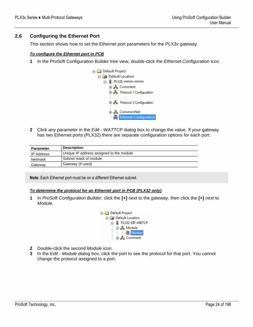
2.6 Configuring the Ethernet Port
This section shows how to set the Ethernet port parameters for the PLX3x gateway.
To configure the Ethernet port in PCB
1 In the ProSoft Configuration Builder tree view, double-click the Ethernet Configuration icon.
2 Click any parameter in the Edit - WATTCP dialog box to change the value. If your gateway has two Ethernet ports (PLX32) there are separate configuration options for each port.
Parameter Description
IP Address Unique IP address assigned to the module
Netmask Subnet mask of module
Gateway Gateway (if used)
Note: Each Ethernet port must be on a different Ethernet subnet.
To determine the protocol for an Ethernet port in PCB (PLX32 only)
1 In ProSoft Configuration Builder, click the [+] next to the gateway, then click the [+] next to Module.
2 Double-click the second Module icon. 3 In the Edit - Module dialog box, click the port to see the protocol for that port. You cannot
change the protocol assigned to a port.
PLX3x Series ♦ Multi-Protocol Gateways Using ProSoft Configuration Builder User Manual
ProSoft Technology, Inc. Page 25 of 198
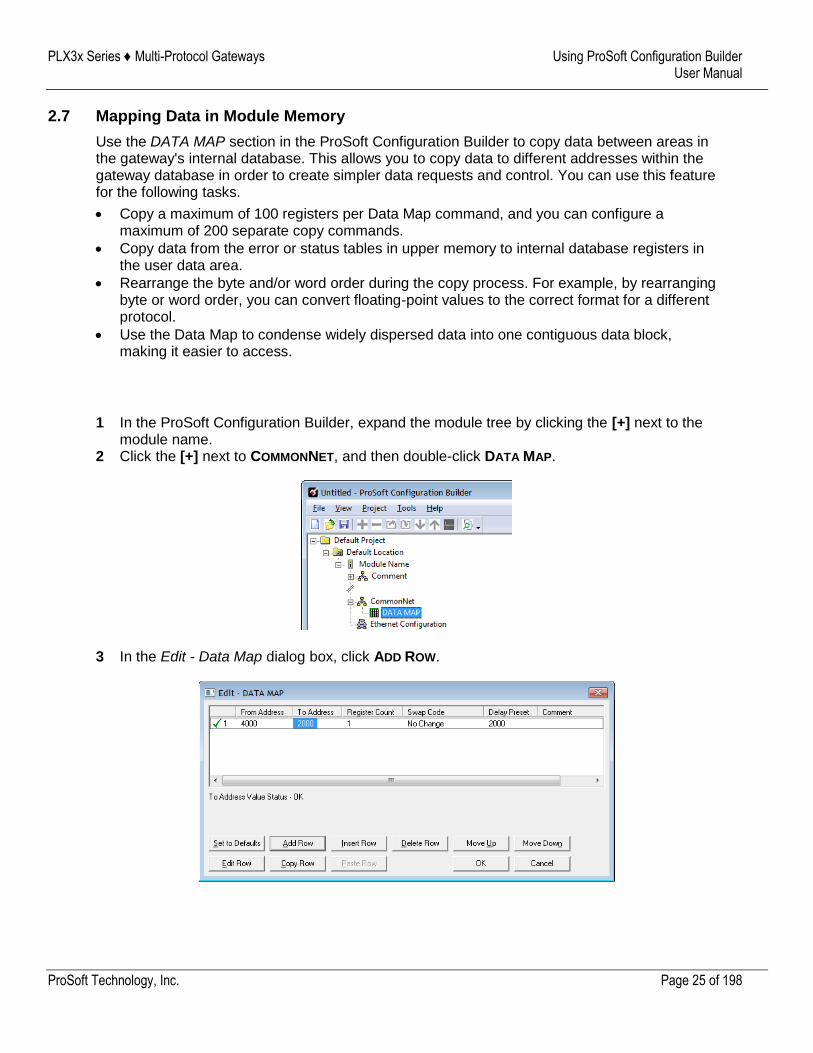
2.7 Mapping Data in Module Memory
Use the DATA MAP section in the ProSoft Configuration Builder to copy data between areas in the gateway's internal database. This allows you to copy data to different addresses within the gateway database in order to create simpler data requests and control. You can use this feature for the following tasks.
Copy a maximum of 100 registers per Data Map command, and you can configure a maximum of 200 separate copy commands.
Copy data from the error or status tables in upper memory to internal database registers in the user data area.
Rearrange the byte and/or word order during the copy process. For example, by rearranging byte or word order, you can convert floating-point values to the correct format for a different protocol.
Use the Data Map to condense widely dispersed data into one contiguous data block, making it easier to access.
1 In the ProSoft Configuration Builder, expand the module tree by clicking the [+] next to the module name.
2 Click the [+] next to COMMONNET, and then double-click DATA MAP.
3 In the Edit - Data Map dialog box, click ADD ROW.
PLX3x Series ♦ Multi-Protocol Gateways Using ProSoft Configuration Builder User Manual
ProSoft Technology, Inc. Page 26 of 198
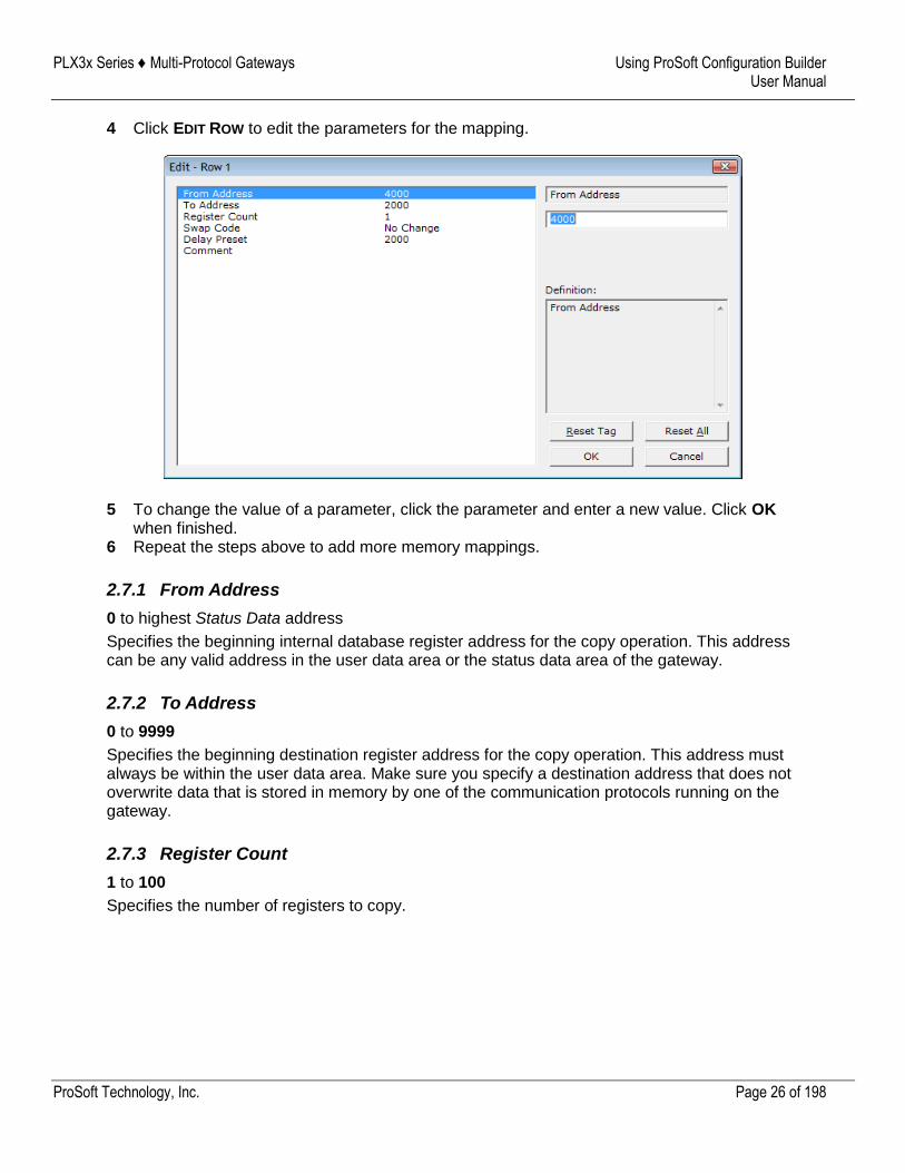
4 Click EDIT ROW to edit the parameters for the mapping.
5 To change the value of a parameter, click the parameter and enter a new value. Click OK when finished.
6 Repeat the steps above to add more memory mappings.
2.7.1 From Address
0 to highest Status Data address
Specifies the beginning internal database register address for the copy operation. This address can be any valid address in the user data area or the status data area of the gateway.
2.7.2 To Address
0 to 9999
Specifies the beginning destination register address for the copy operation. This address must always be within the user data area. Make sure you specify a destination address that does not overwrite data that is stored in memory by one of the communication protocols running on the gateway.
2.7.3 Register Count
1 to 100
Specifies the number of registers to copy.
PLX3x Series ♦ Multi-Protocol Gateways Using ProSoft Configuration Builder User Manual
ProSoft Technology, Inc. Page 27 of 198
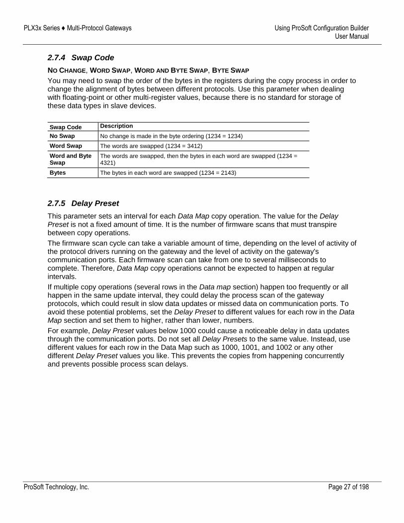
2.7.4 Swap Code
NO CHANGE, WORD SWAP, WORD AND BYTE SWAP, BYTE SWAP
You may need to swap the order of the bytes in the registers during the copy process in order to change the alignment of bytes between different protocols. Use this parameter when dealing with floating-point or other multi-register values, because there is no standard for storage of these data types in slave devices.
Swap Code Description
No Swap No change is made in the byte ordering (1234 = 1234)
Word Swap The words are swapped (1234 = 3412)
Word and Byte Swap
The words are swapped, then the bytes in each word are swapped (1234 = 4321)
Bytes The bytes in each word are swapped (1234 = 2143)
2.7.5 Delay Preset
This parameter sets an interval for each Data Map copy operation. The value for the Delay Preset is not a fixed amount of time. It is the number of firmware scans that must transpire between copy operations.
The firmware scan cycle can take a variable amount of time, depending on the level of activity of the protocol drivers running on the gateway and the level of activity on the gateway's communication ports. Each firmware scan can take from one to several milliseconds to complete. Therefore, Data Map copy operations cannot be expected to happen at regular intervals.
If multiple copy operations (several rows in the Data map section) happen too frequently or all happen in the same update interval, they could delay the process scan of the gateway protocols, which could result in slow data updates or missed data on communication ports. To avoid these potential problems, set the Delay Preset to different values for each row in the Data Map section and set them to higher, rather than lower, numbers.
For example, Delay Preset values below 1000 could cause a noticeable delay in data updates through the communication ports. Do not set all Delay Presets to the same value. Instead, use different values for each row in the Data Map such as 1000, 1001, and 1002 or any other different Delay Preset values you like. This prevents the copies from happening concurrently and prevents possible process scan delays.
PLX3x Series ♦ Multi-Protocol Gateways Using ProSoft Configuration Builder User Manual
ProSoft Technology, Inc. Page 28 of 198
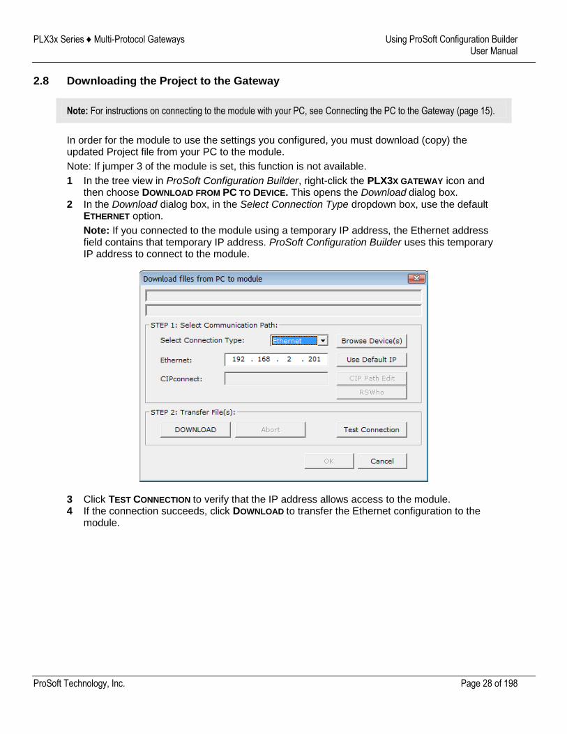
2.8 Downloading the Project to the Gateway
Note: For instructions on connecting to the module with your PC, see Connecting the PC to the Gateway (page 15).
In order for the module to use the settings you configured, you must download (copy) the updated Project file from your PC to the module.
Note: If jumper 3 of the module is set, this function is not available.
1 In the tree view in ProSoft Configuration Builder, right-click the PLX3X GATEWAY icon and then choose DOWNLOAD FROM PC TO DEVICE. This opens the Download dialog box.
2 In the Download dialog box, in the Select Connection Type dropdown box, use the default ETHERNET option.
Note: If you connected to the module using a temporary IP address, the Ethernet address field contains that temporary IP address. ProSoft Configuration Builder uses this temporary IP address to connect to the module.
3 Click TEST CONNECTION to verify that the IP address allows access to the module. 4 If the connection succeeds, click DOWNLOAD to transfer the Ethernet configuration to the
module.
PLX3x Series ♦ Multi-Protocol Gateways Using ProSoft Configuration Builder User Manual
ProSoft Technology, Inc. Page 29 of 198
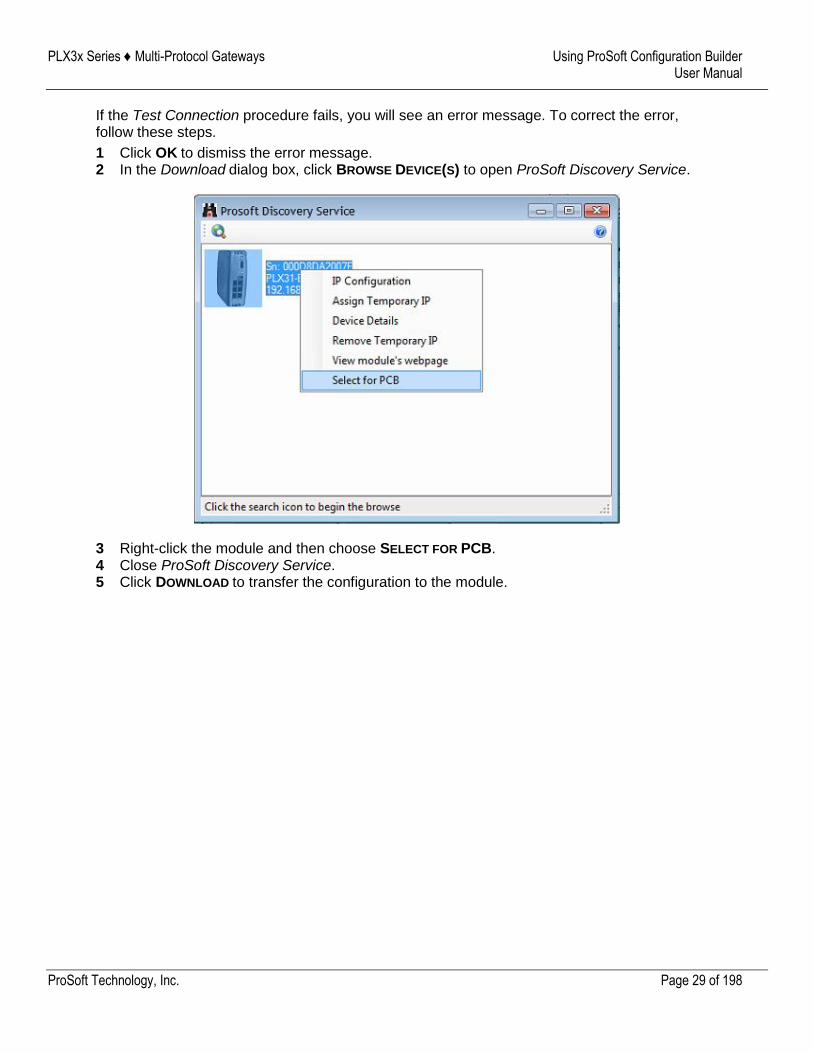
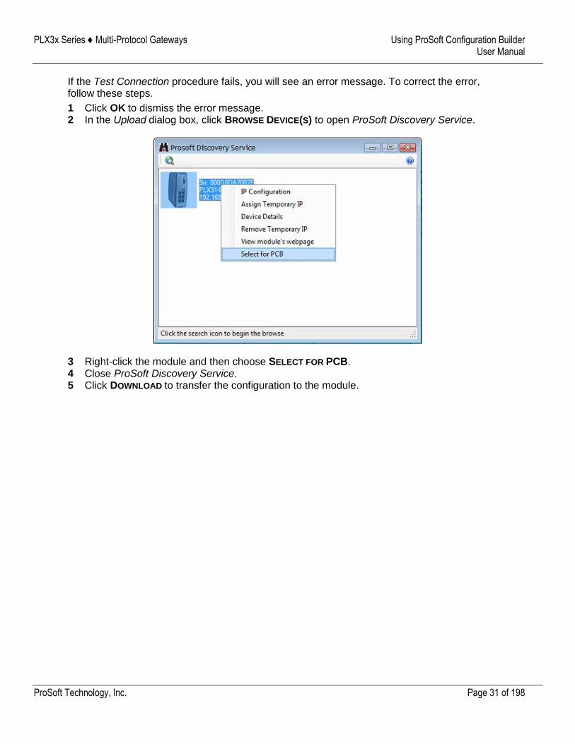
If the Test Connection procedure fails, you will see an error message. To correct the error, follow these steps.
1 Click OK to dismiss the error message. 2 In the Download dialog box, click BROWSE DEVICE(S) to open ProSoft Discovery Service.
3 Right-click the module and then choose SELECT FOR PCB. 4 Close ProSoft Discovery Service. 5 Click DOWNLOAD to transfer the configuration to the module.
PLX3x Series ♦ Multi-Protocol Gateways Using ProSoft Configuration Builder User Manual
ProSoft Technology, Inc. Page 30 of 198
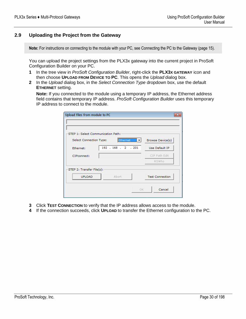
2.9 Uploading the Project from the Gateway
Note: For instructions on connecting to the module with your PC, see Connecting the PC to the Gateway (page 15).
You can upload the project settings from the PLX3x gateway into the current project in ProSoft Configuration Builder on your PC.
1 In the tree view in ProSoft Configuration Builder, right-click the PLX3X GATEWAY icon and then choose UPLOAD FROM DEVICE TO PC. This opens the Upload dialog box.
2 In the Upload dialog box, in the Select Connection Type dropdown box, use the default ETHERNET setting.
Note: If you connected to the module using a temporary IP address, the Ethernet address field contains that temporary IP address. ProSoft Configuration Builder uses this temporary IP address to connect to the module.
3 Click TEST CONNECTION to verify that the IP address allows access to the module. 4 If the connection succeeds, click UPLOAD to transfer the Ethernet configuration to the PC.
PLX3x Series ♦ Multi-Protocol Gateways Using ProSoft Configuration Builder User Manual
ProSoft Technology, Inc. Page 31 of 198
If the Test Connection procedure fails, you will see an error message. To correct the error, follow these steps.
1 Click OK to dismiss the error message. 2 In the Upload dialog box, click BROWSE DEVICE(S) to open ProSoft Discovery Service.
3 Right-click the module and then choose SELECT FOR PCB. 4 Close ProSoft Discovery Service. 5 Click DOWNLOAD to transfer the configuration to the module.
PLX3x Series ♦ Multi-Protocol Gateways Diagnostics and Troubleshooting User Manual
ProSoft Technology, Inc. Page 32 of 198
3 Diagnostics and Troubleshooting
You can troubleshoot the module using several methods:
Monitor the LED indicators on the gateway.
Use the Diagnostics functions in ProSoft Configuration Builder (PCB).
Examine the data in the status data area (upper memory) of the gateway internal memory.
3.1 LED Indicators
The first and quickest is to scan the LEDs on the gateway to determine the existence and possible cause of a problem. The LEDs provide valuable information such as:
The state of each port
System configuration errors
Application errors
Fault indications
PLX3x Series ♦ Multi-Protocol Gateways Diagnostics and Troubleshooting User Manual
ProSoft Technology, Inc. Page 33 of 198
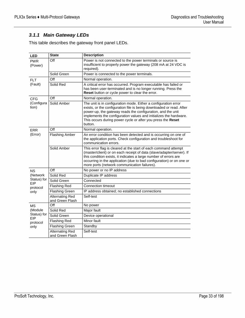
3.1.1 Main Gateway LEDs
This table describes the gateway front panel LEDs.
LED State Description
PWR (Power)
Off Power is not connected to the power terminals or source is insufficient to properly power the gateway (208 mA at 24 VDC is required).
Solid Green Power is connected to the power terminals.
FLT (Fault)
Off Normal operation.
Solid Red A critical error has occurred. Program executable has failed or has been user-terminated and is no longer running. Press the Reset button or cycle power to clear the error.
CFG (Configuration)
Off Normal operation.
Solid Amber The unit is in configuration mode. Either a configuration error exists, or the configuration file is being downloaded or read. After power-up, the gateway reads the configuration, and the unit implements the configuration values and initializes the hardware. This occurs during power cycle or after you press the Reset button.
ERR (Error)
Off Normal operation.
Flashing Amber An error condition has been detected and is occurring on one of the application ports. Check configuration and troubleshoot for communication errors.
Solid Amber This error flag is cleared at the start of each command attempt (master/client) or on each receipt of data (slave/adapter/server). If this condition exists, it indicates a large number of errors are occurring in the application (due to bad configuration) or on one or more ports (network communication failures).
NS (Network Status) for EIP protocol only
Off No power or no IP address
Solid Red Duplicate IP address
Solid Green Connected
Flashing Red Connection timeout
Flashing Green IP address obtained; no established connections
Alternating Red and Green Flash
Self-test
MS (Module Status) for EIP protocol only
Off No power
Solid Red Major fault
Solid Green Device operational
Flashing Red Minor fault
Flashing Green Standby
Alternating Red and Green Flash
Self-test
PLX3x Series ♦ Multi-Protocol Gateways Diagnostics and Troubleshooting User Manual
ProSoft Technology, Inc. Page 34 of 198
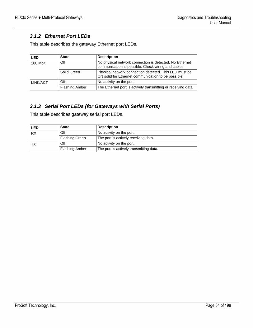
3.1.2 Ethernet Port LEDs
This table describes the gateway Ethernet port LEDs.
LED State Description
100 Mbit Off No physical network connection is detected. No Ethernet communication is possible. Check wiring and cables.
Solid Green Physical network connection detected. This LED must be ON solid for Ethernet communication to be possible.
LINK/ACT Off No activity on the port.
Flashing Amber The Ethernet port is actively transmitting or receiving data.
3.1.3 Serial Port LEDs (for Gateways with Serial Ports)
This table describes gateway serial port LEDs.
LED State Description
RX Off No activity on the port.
Flashing Green The port is actively receiving data.
TX Off No activity on the port.
Flashing Amber The port is actively transmitting data.
PLX3x Series ♦ Multi-Protocol Gateways Diagnostics and Troubleshooting User Manual
ProSoft Technology, Inc. Page 35 of 198
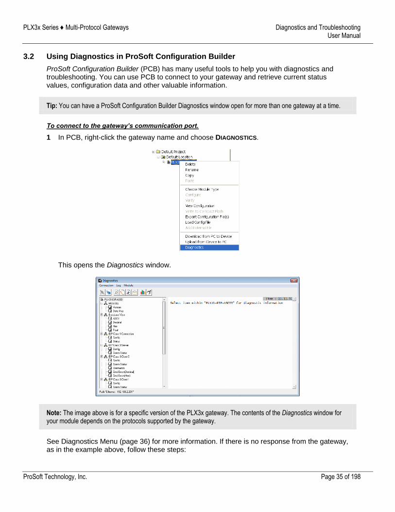
3.2 Using Diagnostics in ProSoft Configuration Builder
ProSoft Configuration Builder (PCB) has many useful tools to help you with diagnostics and troubleshooting. You can use PCB to connect to your gateway and retrieve current status values, configuration data and other valuable information.
Tip: You can have a ProSoft Configuration Builder Diagnostics window open for more than one gateway at a time.
To connect to the gateway’s communication port.
1 In PCB, right-click the gateway name and choose DIAGNOSTICS.
This opens the Diagnostics window.
Note: The image above is for a specific version of the PLX3x gateway. The contents of the Diagnostics window for your module depends on the protocols supported by the gateway.
See Diagnostics Menu (page 36) for more information. If there is no response from the gateway, as in the example above, follow these steps:
PLX3x Series ♦ Multi-Protocol Gateways Diagnostics and Troubleshooting User Manual
ProSoft Technology, Inc. Page 36 of 198
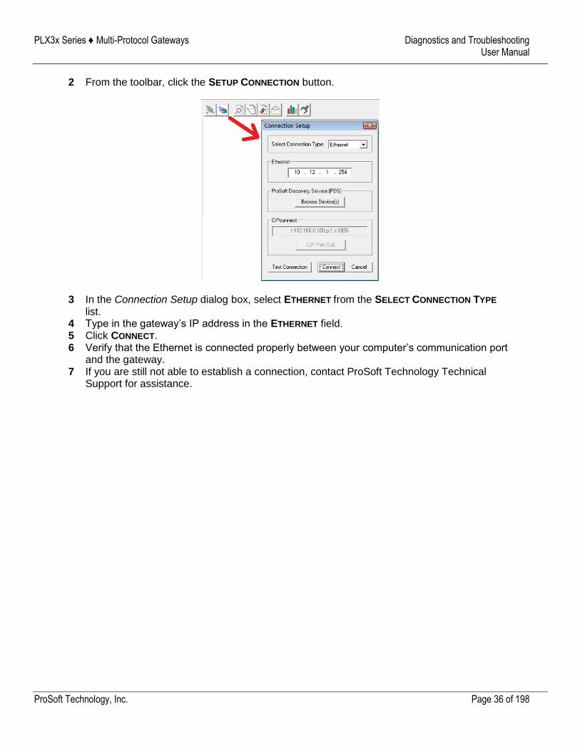
2 From the toolbar, click the SETUP CONNECTION button.
3 In the Connection Setup dialog box, select ETHERNET from the SELECT CONNECTION TYPE list.
4 Type in the gateway’s IP address in the ETHERNET field. 5 Click CONNECT. 6 Verify that the Ethernet is connected properly between your computer’s communication port
and the gateway. 7 If you are still not able to establish a connection, contact ProSoft Technology Technical
Support for assistance.
PLX3x Series ♦ Multi-Protocol Gateways Diagnostics and Troubleshooting User Manual
ProSoft Technology, Inc. Page 37 of 198
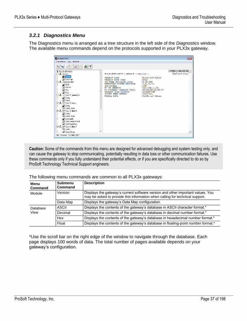
3.2.1 Diagnostics Menu
The Diagnostics menu is arranged as a tree structure in the left side of the Diagnostics window. The available menu commands depend on the protocols supported in your PLX3x gateway.
Caution: Some of the commands from this menu are designed for advanced debugging and system testing only, and can cause the gateway to stop communicating, potentially resulting in data loss or other communication failures. Use these commands only if you fully understand their potential effects, or if you are specifically directed to do so by ProSoft Technology Technical Support engineers.
The following menu commands are common to all PLX3x gateways:
Menu Command
Submenu Command
Description
Module Version Displays the gateway’s current software version and other important values. You may be asked to provide this information when calling for technical support.
Data Map Displays the gateway’s Data Map configuration.
Database View
ASCII Displays the contents of the gateway’s database in ASCII character format.*
Decimal Displays the contents of the gateway’s database in decimal number format.*
Hex Displays the contents of the gateway’s database in hexadecimal number format.*
Float Displays the contents of the gateway’s database in floating-point number format.*
*Use the scroll bar on the right edge of the window to navigate through the database. Each page displays 100 words of data. The total number of pages available depends on your gateway’s configuration.
PLX3x Series ♦ Multi-Protocol Gateways Diagnostics and Troubleshooting User Manual
ProSoft Technology, Inc. Page 38 of 198
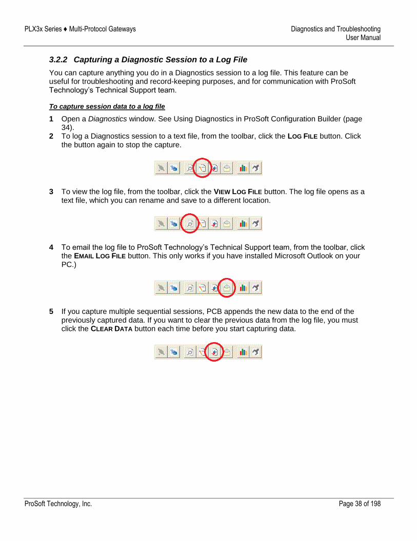
3.2.2 Capturing a Diagnostic Session to a Log File
You can capture anything you do in a Diagnostics session to a log file. This feature can be useful for troubleshooting and record-keeping purposes, and for communication with ProSoft Technology’s Technical Support team.
To capture session data to a log file
1 Open a Diagnostics window. See Using Diagnostics in ProSoft Configuration Builder (page 34).
2 To log a Diagnostics session to a text file, from the toolbar, click the LOG FILE button. Click the button again to stop the capture.
3 To view the log file, from the toolbar, click the VIEW LOG FILE button. The log file opens as a text file, which you can rename and save to a different location.
4 To email the log file to ProSoft Technology’s Technical Support team, from the toolbar, click the EMAIL LOG FILE button. This only works if you have installed Microsoft Outlook on your PC.)
5 If you capture multiple sequential sessions, PCB appends the new data to the end of the previously captured data. If you want to clear the previous data from the log file, you must click the CLEAR DATA button each time before you start capturing data.
PLX3x Series ♦ Multi-Protocol Gateways Diagnostics and Troubleshooting User Manual
ProSoft Technology, Inc. Page 39 of 198
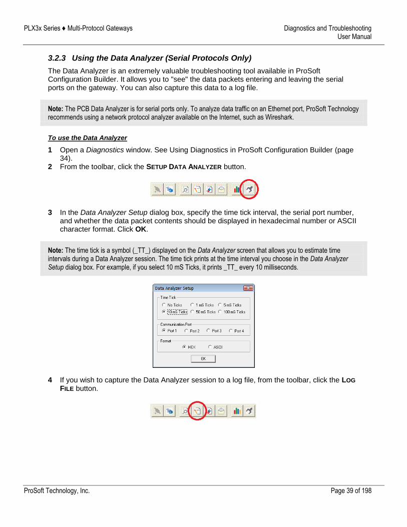
3.2.3 Using the Data Analyzer (Serial Protocols Only)
The Data Analyzer is an extremely valuable troubleshooting tool available in ProSoft Configuration Builder. It allows you to "see" the data packets entering and leaving the serial ports on the gateway. You can also capture this data to a log file.
Note: The PCB Data Analyzer is for serial ports only. To analyze data traffic on an Ethernet port, ProSoft Technology recommends using a network protocol analyzer available on the Internet, such as Wireshark.
To use the Data Analyzer
1 Open a Diagnostics window. See Using Diagnostics in ProSoft Configuration Builder (page 34).
2 From the toolbar, click the SETUP DATA ANALYZER button.
3 In the Data Analyzer Setup dialog box, specify the time tick interval, the serial port number, and whether the data packet contents should be displayed in hexadecimal number or ASCII character format. Click OK.
Note: The time tick is a symbol (_TT_) displayed on the Data Analyzer screen that allows you to estimate time intervals during a Data Analyzer session. The time tick prints at the time interval you choose in the Data Analyzer Setup dialog box. For example, if you select 10 mS Ticks, it prints _TT_ every 10 milliseconds.
4 If you wish to capture the Data Analyzer session to a log file, from the toolbar, click the LOG
FILE button.
PLX3x Series ♦ Multi-Protocol Gateways Diagnostics and Troubleshooting User Manual
ProSoft Technology, Inc. Page 40 of 198
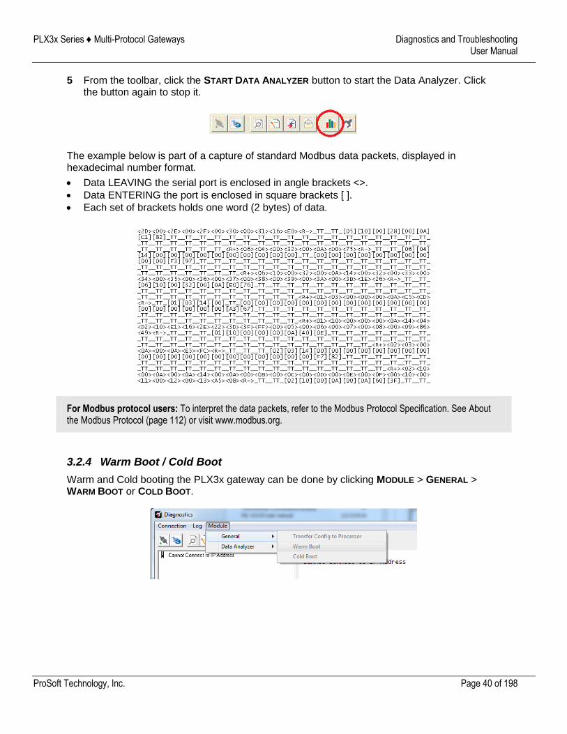
5 From the toolbar, click the START DATA ANALYZER button to start the Data Analyzer. Click the button again to stop it.
The example below is part of a capture of standard Modbus data packets, displayed in hexadecimal number format.
Data LEAVING the serial port is enclosed in angle brackets <>.
Data ENTERING the port is enclosed in square brackets [ ].
Each set of brackets holds one word (2 bytes) of data.
For Modbus protocol users: To interpret the data packets, refer to the Modbus Protocol Specification. See About the Modbus Protocol (page 112) or visit www.modbus.org.
3.2.4 Warm Boot / Cold Boot
Warm and Cold booting the PLX3x gateway can be done by clicking MODULE > GENERAL > WARM BOOT or COLD BOOT.

PLX3x Series ♦ Multi-Protocol Gateways Diagnostics and Troubleshooting User Manual
ProSoft Technology, Inc. Page 41 of 198
3.3 Gateway Status Data in Upper Memory
The gateway writes useful module status data in dedicated upper memory locations in its internal database. The location of this status data area depends on the protocols supported by your gateway. You can use the Data Map function in Prosoft Configuration Builder to map this data into the user data area of the gateway’s database (registers 0 through 9999). Remote devices, such as HMIs or processors can then access the status data. See Mapping Data in Module Memory (page 25).
3.3.1 General Gateway Status Data in Upper Memory
The following table describes the contents of the gateway’s general status data area.
Register Address Description
14000 through 14001 Program Cycle Counter
14002 through 14004 Product Code (ASCII)
14005 through 14009 Product Revision (ASCII)
14010 through 14014 Operating System Revision (ASCII)
14015 through 14019 OS Run Number (ASCII)
PLX3x Series ♦ Multi-Protocol Gateways Diagnostics and Troubleshooting User Manual
ProSoft Technology, Inc. Page 42 of 198
3.3.2 Protocol-Specific Status Data in Upper Memory
The PLX3x gateway also has upper memory locations for protocol-specific status data. The location of the status data area for the gateway protocol drivers depend on the protocols. For more information, see:
EIP Status Data in Upper Memory (page 70)
MBTCP Status Data in Upper Memory (page 107)
MBS Status Data in Upper Memory (page 124)
ASCII Status Data in Upper Memory (page 142)
SIE Status Data in Upper Memory (page 162)
PND Status Data in Upper Memory (page 195)
PLX3x Series ♦ Multi-Protocol Gateways Hardware Information User Manual
ProSoft Technology, Inc. Page 43 of 198
4 Hardware Information
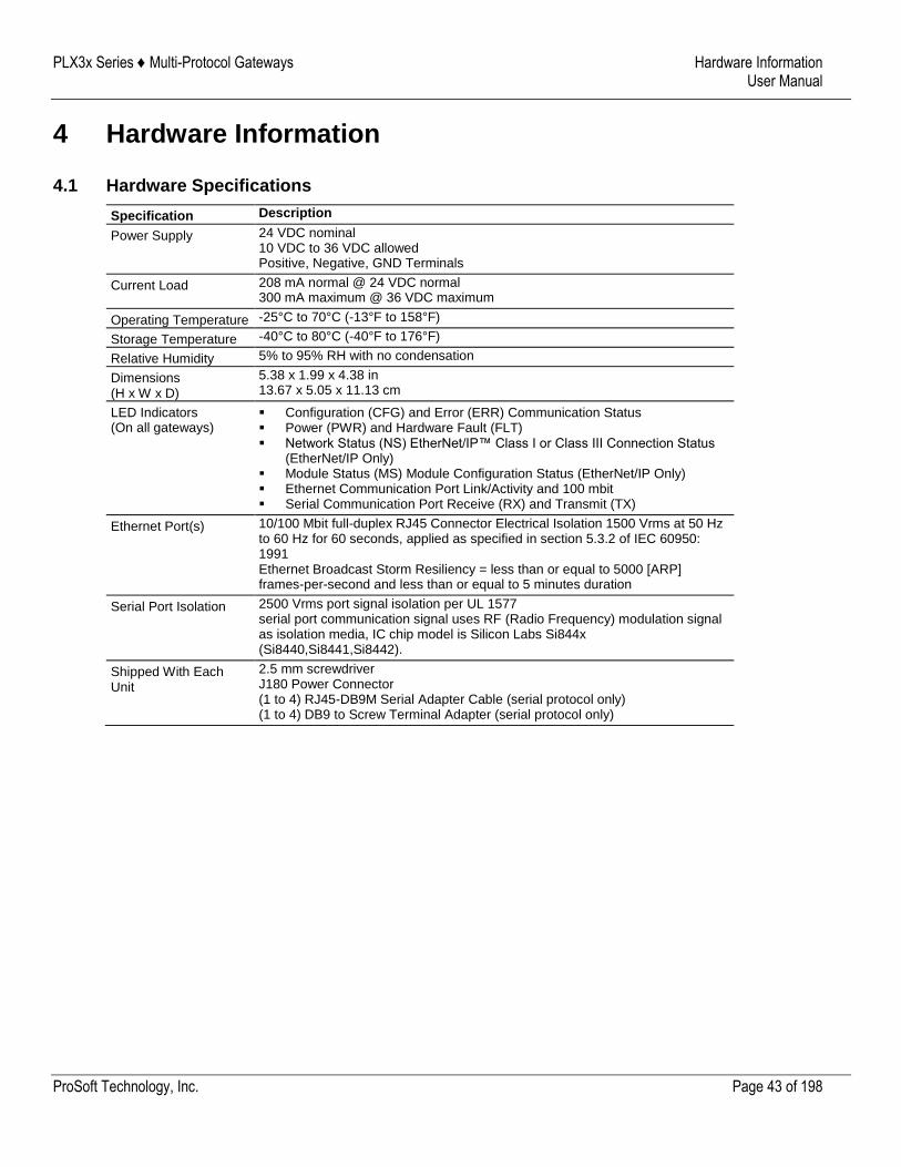
4.1 Hardware Specifications
Specification Description
Power Supply 24 VDC nominal 10 VDC to 36 VDC allowed Positive, Negative, GND Terminals
Current Load 208 mA normal @ 24 VDC normal 300 mA maximum @ 36 VDC maximum
Operating Temperature -25°C to 70°C (-13°F to 158°F)
Storage Temperature -40°C to 80°C (-40°F to 176°F)
Relative Humidity 5% to 95% RH with no condensation
Dimensions (H x W x D)
5.38 x 1.99 x 4.38 in 13.67 x 5.05 x 11.13 cm
LED Indicators (On all gateways)
Configuration (CFG) and Error (ERR) Communication Status Power (PWR) and Hardware Fault (FLT) Network Status (NS) EtherNet/IP™ Class I or Class III Connection Status
(EtherNet/IP Only) Module Status (MS) Module Configuration Status (EtherNet/IP Only) Ethernet Communication Port Link/Activity and 100 mbit Serial Communication Port Receive (RX) and Transmit (TX)
Ethernet Port(s)
10/100 Mbit full-duplex RJ45 Connector Electrical Isolation 1500 Vrms at 50 Hz to 60 Hz for 60 seconds, applied as specified in section 5.3.2 of IEC 60950: 1991 Ethernet Broadcast Storm Resiliency = less than or equal to 5000 [ARP] frames-per-second and less than or equal to 5 minutes duration
Serial Port Isolation 2500 Vrms port signal isolation per UL 1577 serial port communication signal uses RF (Radio Frequency) modulation signal as isolation media, IC chip model is Silicon Labs Si844x (Si8440,Si8441,Si8442).
Shipped With Each Unit
2.5 mm screwdriver J180 Power Connector (1 to 4) RJ45-DB9M Serial Adapter Cable (serial protocol only) (1 to 4) DB9 to Screw Terminal Adapter (serial protocol only)
PLX3x Series ♦ Multi-Protocol Gateways Hardware Information User Manual
ProSoft Technology, Inc. Page 44 of 198
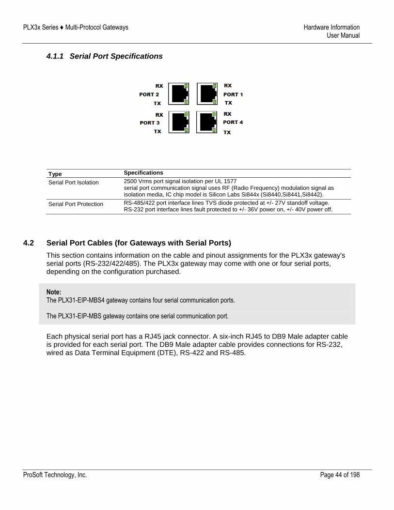
4.1.1 Serial Port Specifications
Type Specifications
Serial Port Isolation 2500 Vrms port signal isolation per UL 1577 serial port communication signal uses RF (Radio Frequency) modulation signal as isolation media, IC chip model is Silicon Labs Si844x (Si8440,Si8441,Si8442).
Serial Port Protection RS-485/422 port interface lines TVS diode protected at +/- 27V standoff voltage. RS-232 port interface lines fault protected to +/- 36V power on, +/- 40V power off.
4.2 Serial Port Cables (for Gateways with Serial Ports)
This section contains information on the cable and pinout assignments for the PLX3x gateway's serial ports (RS-232/422/485). The PLX3x gateway may come with one or four serial ports, depending on the configuration purchased.
Note: The PLX31-EIP-MBS4 gateway contains four serial communication ports.
The PLX31-EIP-MBS gateway contains one serial communication port.
Each physical serial port has a RJ45 jack connector. A six-inch RJ45 to DB9 Male adapter cable is provided for each serial port. The DB9 Male adapter cable provides connections for RS-232, wired as Data Terminal Equipment (DTE), RS-422 and RS-485.
PLX3x Series ♦ Multi-Protocol Gateways Hardware Information User Manual
ProSoft Technology, Inc. Page 45 of 198
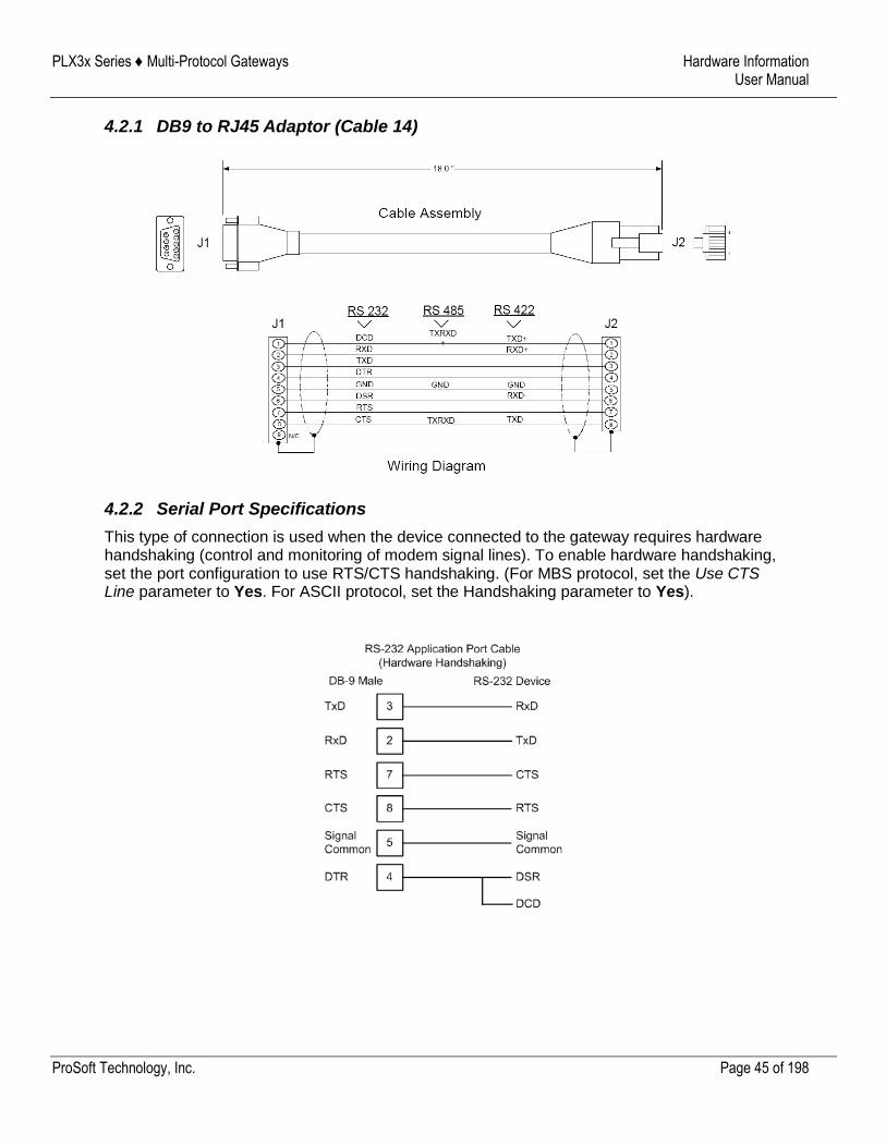
4.2.1 DB9 to RJ45 Adaptor (Cable 14)
4.2.2 Serial Port Specifications
This type of connection is used when the device connected to the gateway requires hardware handshaking (control and monitoring of modem signal lines). To enable hardware handshaking, set the port configuration to use RTS/CTS handshaking. (For MBS protocol, set the Use CTS Line parameter to Yes. For ASCII protocol, set the Handshaking parameter to Yes).
PLX3x Series ♦ Multi-Protocol Gateways Hardware Information User Manual
ProSoft Technology, Inc. Page 46 of 198
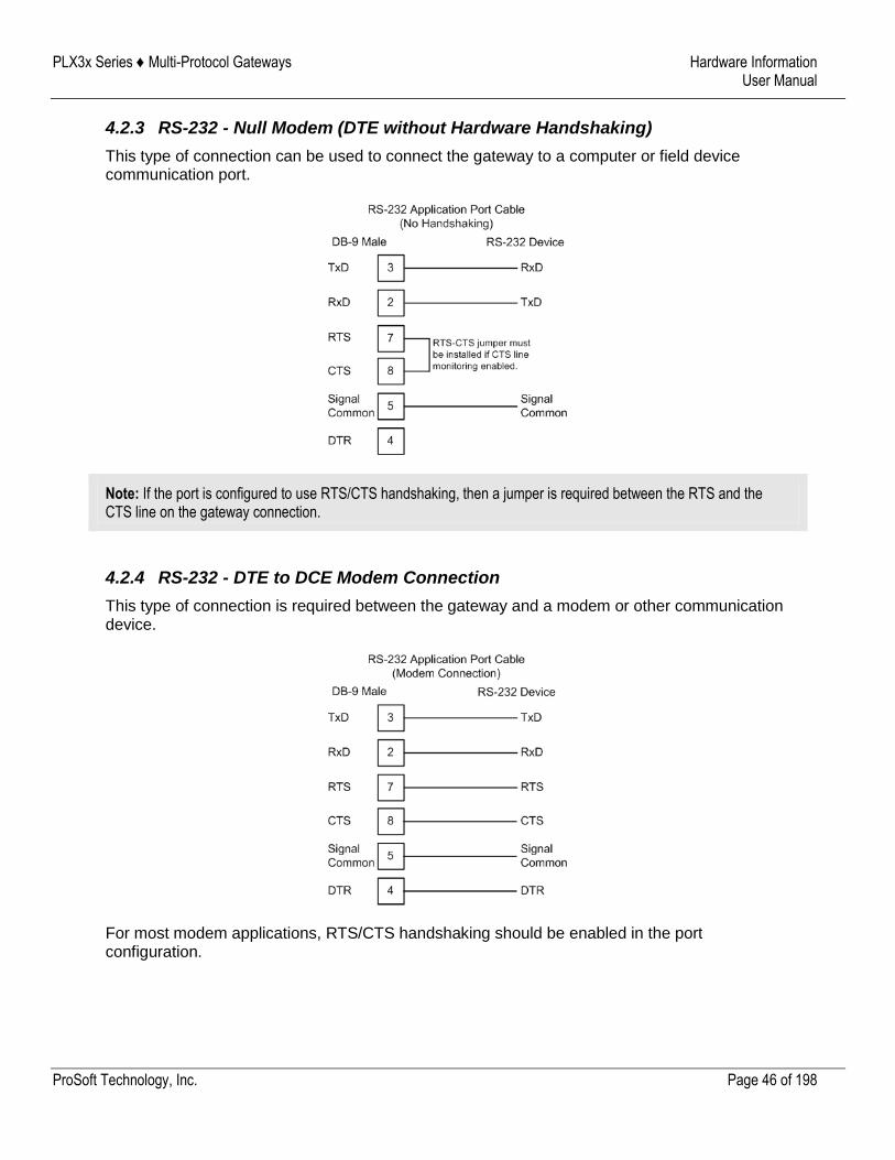
4.2.3 RS-232 - Null Modem (DTE without Hardware Handshaking)
This type of connection can be used to connect the gateway to a computer or field device communication port.
Note: If the port is configured to use RTS/CTS handshaking, then a jumper is required between the RTS and the CTS line on the gateway connection.
4.2.4 RS-232 - DTE to DCE Modem Connection
This type of connection is required between the gateway and a modem or other communication device.
For most modem applications, RTS/CTS handshaking should be enabled in the port configuration.
PLX3x Series ♦ Multi-Protocol Gateways Hardware Information User Manual
ProSoft Technology, Inc. Page 47 of 198
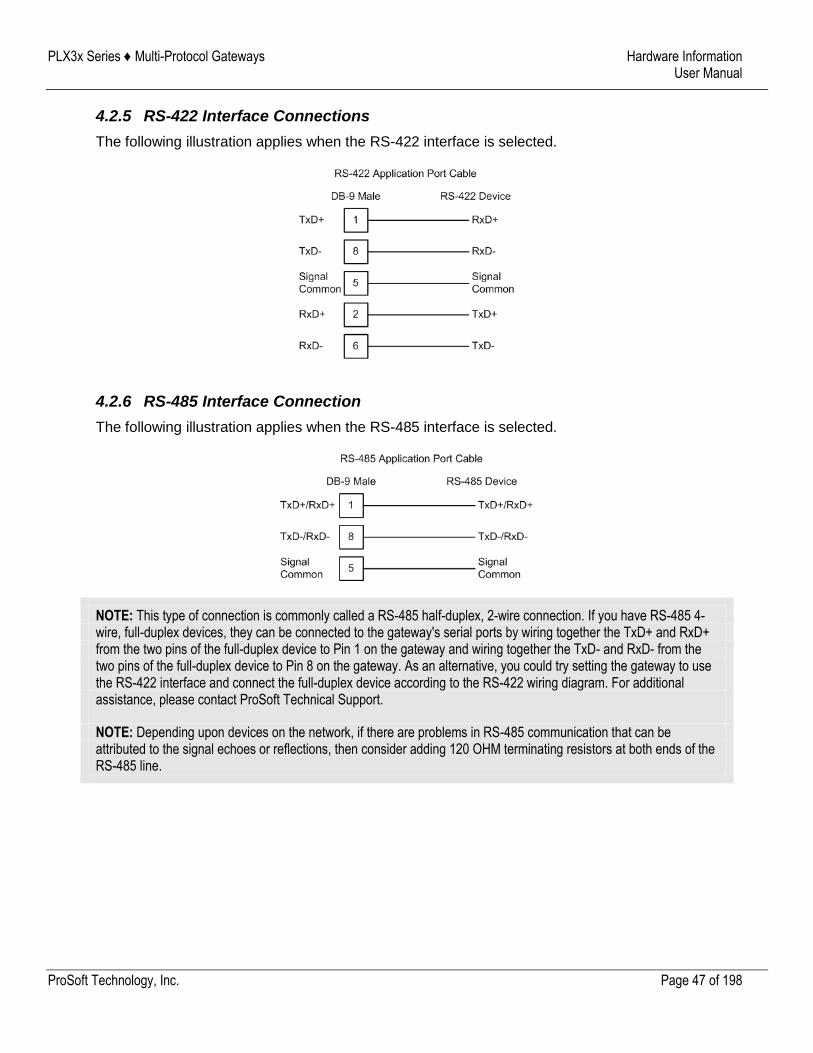
4.2.5 RS-422 Interface Connections
The following illustration applies when the RS-422 interface is selected.
4.2.6 RS-485 Interface Connection
The following illustration applies when the RS-485 interface is selected.
NOTE: This type of connection is commonly called a RS-485 half-duplex, 2-wire connection. If you have RS-485 4-wire, full-duplex devices, they can be connected to the gateway's serial ports by wiring together the TxD+ and RxD+ from the two pins of the full-duplex device to Pin 1 on the gateway and wiring together the TxD- and RxD- from the two pins of the full-duplex device to Pin 8 on the gateway. As an alternative, you could try setting the gateway to use the RS-422 interface and connect the full-duplex device according to the RS-422 wiring diagram. For additional assistance, please contact ProSoft Technical Support.
NOTE: Depending upon devices on the network, if there are problems in RS-485 communication that can be attributed to the signal echoes or reflections, then consider adding 120 OHM terminating resistors at both ends of the RS-485 line.
PLX3x Series ♦ Multi-Protocol Gateways EIP Protocol User Manual
ProSoft Technology, Inc. Page 48 of 198
5 EIP Protocol
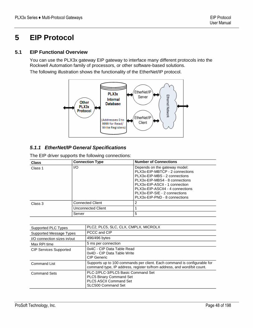
5.1 EIP Functional Overview
You can use the PLX3x gateway EIP gateway to interface many different protocols into the Rockwell Automation family of processors, or other software-based solutions.
The following illustration shows the functionality of the EtherNet/IP protocol.
5.1.1 EtherNet/IP General Specifications
The EIP driver supports the following connections:
Class Connection Type Number of Connections
Class 1 I/O Depends on the gateway model: PLX3x-EIP-MBTCP - 2 connections PLX3x-EIP-MBS - 2 connections PLX3x-EIP-MBS4 - 8 connections PLX3x-EIP-ASCII - 1 connection PLX3x-EIP-ASCII4 - 4 connections PLX3x-EIP-SIE - 2 connections PLX3x-EIP-PND - 8 connections
Class 3 Connected Client 2
Unconnected Client 1
Server 5
Supported PLC Types PLC2, PLC5, SLC, CLX, CMPLX, MICROLX
Supported Message Types PCCC and CIP
I/O connection sizes in/out 496/496 bytes
Max RPI time 5 ms per connection
CIP Services Supported 0x4C - CIP Data Table Read 0x4D - CIP Data Table Write CIP Generic
Command List Supports up to 100 commands per client. Each command is configurable for command type, IP address, register to/from address, and word/bit count.
Command Sets PLC-2/PLC-3/PLC5 Basic Command Set PLC5 Binary Command Set PLC5 ASCII Command Set SLC500 Command Set
PLX3x Series ♦ Multi-Protocol Gateways EIP Protocol User Manual
ProSoft Technology, Inc. Page 49 of 198
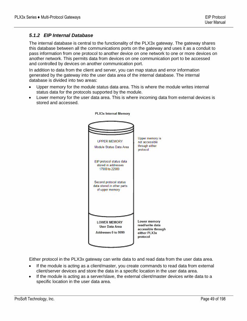
5.1.2 EIP Internal Database
The internal database is central to the functionality of the PLX3x gateway. The gateway shares this database between all the communications ports on the gateway and uses it as a conduit to pass information from one protocol to another device on one network to one or more devices on another network. This permits data from devices on one communication port to be accessed and controlled by devices on another communication port.
In addition to data from the client and server, you can map status and error information generated by the gateway into the user data area of the internal database. The internal database is divided into two areas:
Upper memory for the module status data area. This is where the module writes internal status data for the protocols supported by the module.
Lower memory for the user data area. This is where incoming data from external devices is stored and accessed.
Either protocol in the PLX3x gateway can write data to and read data from the user data area.
If the module is acting as a client/master, you create commands to read data from external client/server devices and store the data in a specific location in the user data area.
If the module is acting as a server/slave, the external client/master devices write data to a specific location in the user data area.
PLX3x Series ♦ Multi-Protocol Gateways EIP Protocol User Manual
ProSoft Technology, Inc. Page 50 of 198
Note: If you want to access module status data in the upper memory, you can use the data mapping feature in the gateway to copy data from the module status data area to the user data area. See Mapping Data in Module Memory (page 25). Otherwise, you can use the diagnostic functions in ProSoft Configuration Builder to view module status data. For more information on the module status data, see Network Diagnostics (page 69).
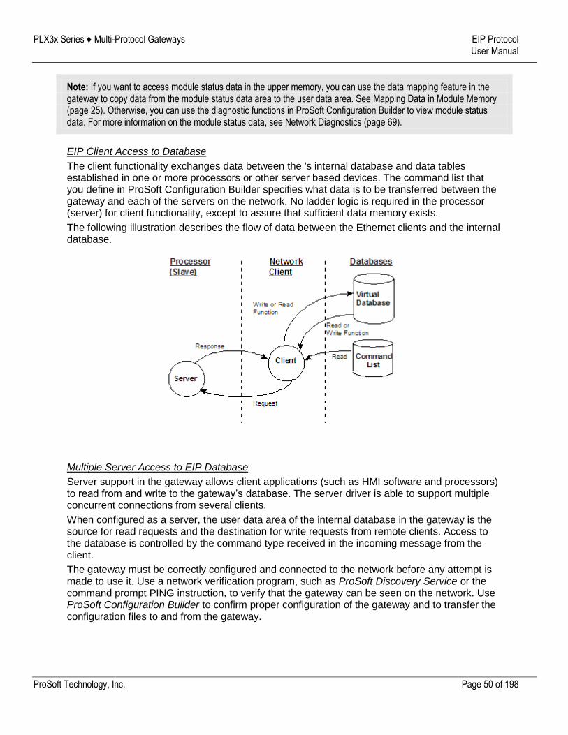
EIP Client Access to Database
The client functionality exchanges data between the 's internal database and data tables established in one or more processors or other server based devices. The command list that you define in ProSoft Configuration Builder specifies what data is to be transferred between the gateway and each of the servers on the network. No ladder logic is required in the processor (server) for client functionality, except to assure that sufficient data memory exists.
The following illustration describes the flow of data between the Ethernet clients and the internal database.
Multiple Server Access to EIP Database
Server support in the gateway allows client applications (such as HMI software and processors) to read from and write to the gateway’s database. The server driver is able to support multiple concurrent connections from several clients.
When configured as a server, the user data area of the internal database in the gateway is the source for read requests and the destination for write requests from remote clients. Access to the database is controlled by the command type received in the incoming message from the client.
The gateway must be correctly configured and connected to the network before any attempt is made to use it. Use a network verification program, such as ProSoft Discovery Service or the command prompt PING instruction, to verify that the gateway can be seen on the network. Use ProSoft Configuration Builder to confirm proper configuration of the gateway and to transfer the configuration files to and from the gateway.
PLX3x Series ♦ Multi-Protocol Gateways EIP Protocol User Manual
ProSoft Technology, Inc. Page 51 of 198
5.2 EIP Configuration
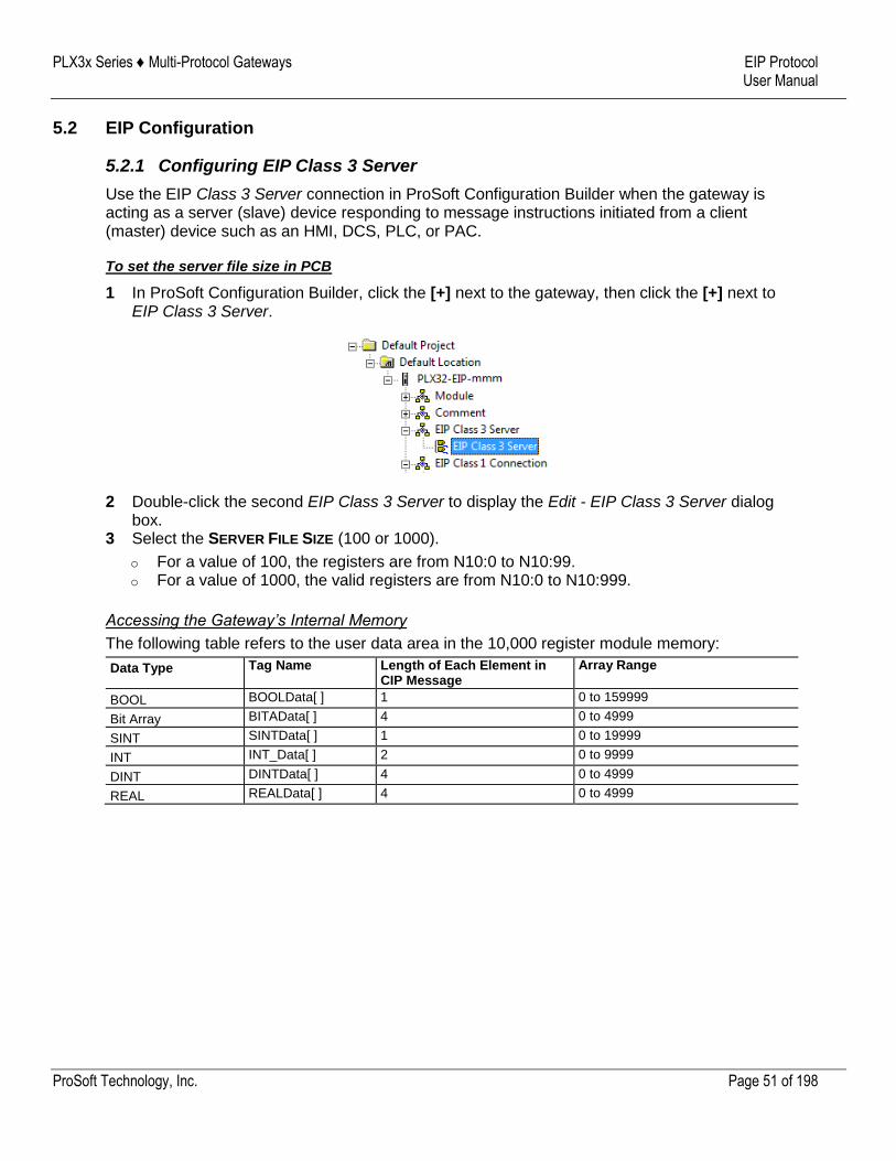
5.2.1 Configuring EIP Class 3 Server
Use the EIP Class 3 Server connection in ProSoft Configuration Builder when the gateway is acting as a server (slave) device responding to message instructions initiated from a client (master) device such as an HMI, DCS, PLC, or PAC.
To set the server file size in PCB
1 In ProSoft Configuration Builder, click the [+] next to the gateway, then click the [+] next to EIP Class 3 Server.
2 Double-click the second EIP Class 3 Server to display the Edit - EIP Class 3 Server dialog box.
3 Select the SERVER FILE SIZE (100 or 1000).
o For a value of 100, the registers are from N10:0 to N10:99. o For a value of 1000, the valid registers are from N10:0 to N10:999.
Accessing the Gateway’s Internal Memory
The following table refers to the user data area in the 10,000 register module memory:
Data Type Tag Name Length of Each Element in CIP Message
Array Range
BOOL BOOLData[ ] 1 0 to 159999
Bit Array BITAData[ ] 4 0 to 4999
SINT SINTData[ ] 1 0 to 19999
INT INT_Data[ ] 2 0 to 9999
DINT DINTData[ ] 4 0 to 4999
REAL REALData[ ] 4 0 to 4999
PLX3x Series ♦ Multi-Protocol Gateways EIP Protocol User Manual
ProSoft Technology, Inc. Page 52 of 198
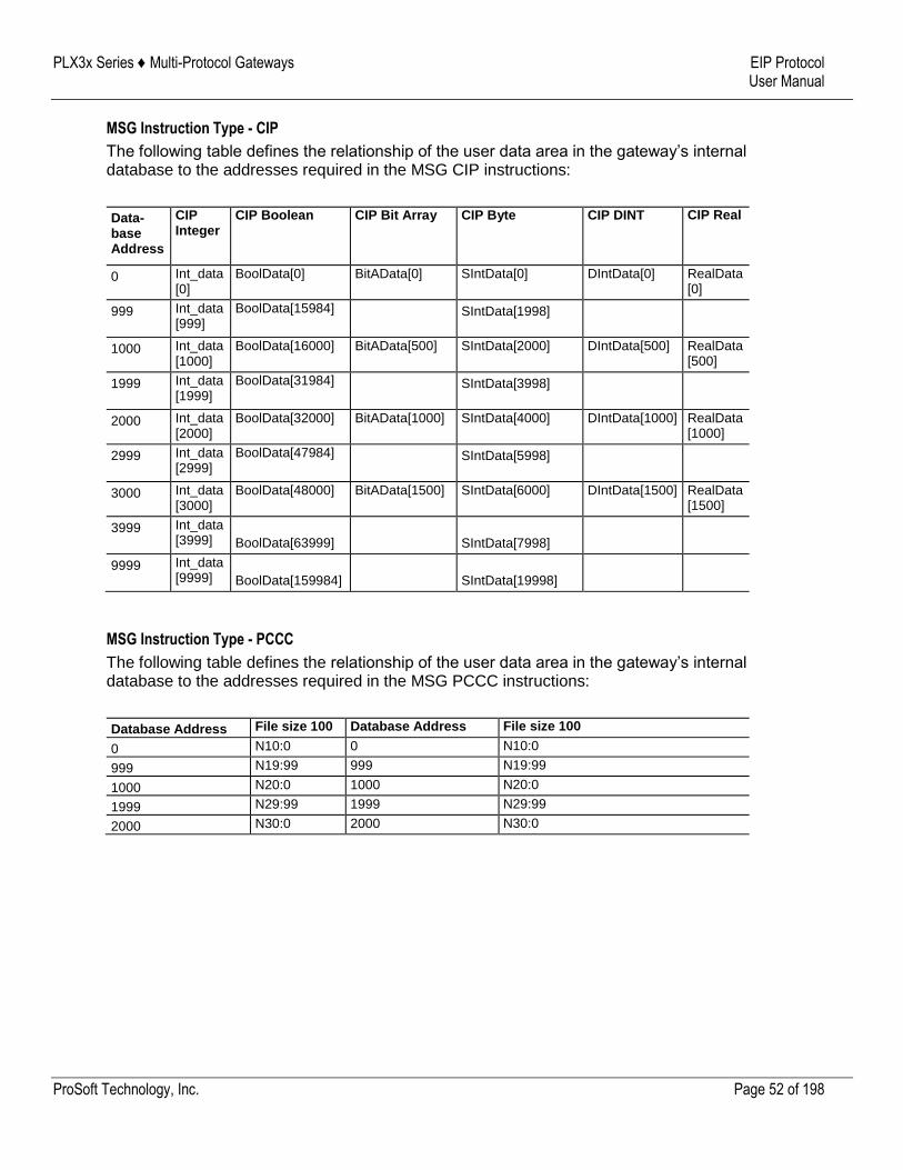
MSG Instruction Type - CIP
The following table defines the relationship of the user data area in the gateway’s internal database to the addresses required in the MSG CIP instructions:
Data- base Address
CIP Integer
CIP Boolean CIP Bit Array CIP Byte CIP DINT CIP Real
0 Int_data[0]
BoolData[0] BitAData[0] SIntData[0] DIntData[0] RealData [0]
999 Int_data[999]
BoolData[15984] SIntData[1998]
1000 Int_data[1000]
BoolData[16000] BitAData[500] SIntData[2000] DIntData[500] RealData [500]
1999 Int_data[1999]
BoolData[31984] SIntData[3998]
2000 Int_data[2000]
BoolData[32000] BitAData[1000] SIntData[4000] DIntData[1000] RealData [1000]
2999 Int_data[2999]
BoolData[47984] SIntData[5998]
3000 Int_data[3000]
BoolData[48000] BitAData[1500] SIntData[6000] DIntData[1500] RealData [1500]
3999 Int_data[3999] BoolData[63999] SIntData[7998]
9999 Int_data[9999] BoolData[159984] SIntData[19998]
MSG Instruction Type - PCCC
The following table defines the relationship of the user data area in the gateway’s internal database to the addresses required in the MSG PCCC instructions:
Database Address File size 100 Database Address File size 100
0 N10:0 0 N10:0
999 N19:99 999 N19:99
1000 N20:0 1000 N20:0
1999 N29:99 1999 N29:99
2000 N30:0 2000 N30:0
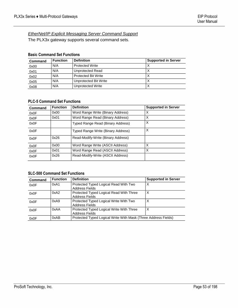
PLX3x Series ♦ Multi-Protocol Gateways EIP Protocol User Manual
ProSoft Technology, Inc. Page 53 of 198
EtherNet/IP Explicit Messaging Server Command Support
The PLX3x gateway supports several command sets.
Basic Command Set Functions
Command Function Definition Supported in Server
0x00 N/A Protected Write X
0x01 N/A Unprotected Read X
0x02 N/A Protected Bit Write X
0x05 N/A Unprotected Bit Write X
0x08 N/A Unprotected Write X
PLC-5 Command Set Functions
Command Function Definition Supported in Server
0x0F 0x00 Word Range Write (Binary Address) X
0x0F 0x01 Word Range Read (Binary Address) X
0x0F Typed Range Read (Binary Address) X
0x0F Typed Range Write (Binary Address) X
0x0F 0x26 Read-Modify-Write (Binary Address)
0x0F 0x00 Word Range Write (ASCII Address) X
0x0F 0x01 Word Range Read (ASCII Address) X
0x0F 0x26 Read-Modify-Write (ASCII Address)
SLC-500 Command Set Functions
Command Function Definition Supported in Server
0x0F 0xA1 Protected Typed Logical Read With Two Address Fields
X
0x0F 0xA2 Protected Typed Logical Read With Three Address Fields
X
0x0F 0xA9 Protected Typed Logical Write With Two Address Fields
X
0x0F 0xAA Protected Typed Logical Write With Three Address Fields
X
0x0F 0xAB Protected Typed Logical Write With Mask (Three Address Fields)
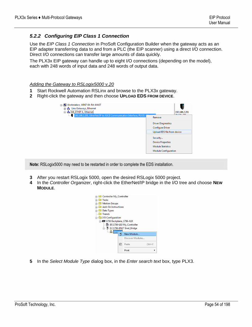
PLX3x Series ♦ Multi-Protocol Gateways EIP Protocol User Manual
ProSoft Technology, Inc. Page 54 of 198
5.2.2 Configuring EIP Class 1 Connection
Use the EIP Class 1 Connection in ProSoft Configuration Builder when the gateway acts as an EIP adapter transferring data to and from a PLC (the EIP scanner) using a direct I/O connection. Direct I/O connections can transfer large amounts of data quickly.
The PLX3x EIP gateway can handle up to eight I/O connections (depending on the model), each with 248 words of input data and 248 words of output data.
Adding the Gateway to RSLogix5000 v.20
1 Start Rockwell Automation RSLinx and browse to the PLX3x gateway. 2 Right-click the gateway and then choose UPLOAD EDS FROM DEVICE.
Note: RSLogix5000 may need to be restarted in order to complete the EDS installation.
3 After you restart RSLogix 5000, open the desired RSLogix 5000 project. 4 In the Controller Organizer, right-click the EtherNet/IP bridge in the I/O tree and choose NEW
MODULE.
5 In the Select Module Type dialog box, in the Enter search text box, type PLX3.
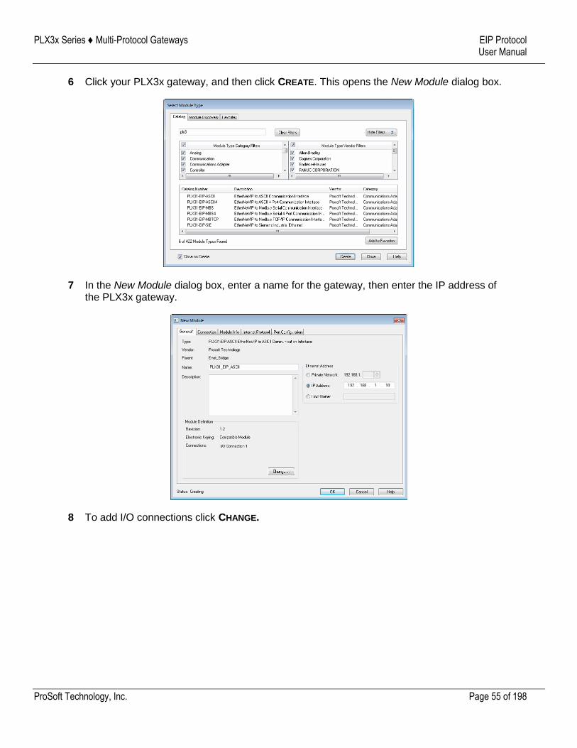
PLX3x Series ♦ Multi-Protocol Gateways EIP Protocol User Manual
ProSoft Technology, Inc. Page 55 of 198
6 Click your PLX3x gateway, and then click CREATE. This opens the New Module dialog box.
7 In the New Module dialog box, enter a name for the gateway, then enter the IP address of the PLX3x gateway.
8 To add I/O connections click CHANGE.
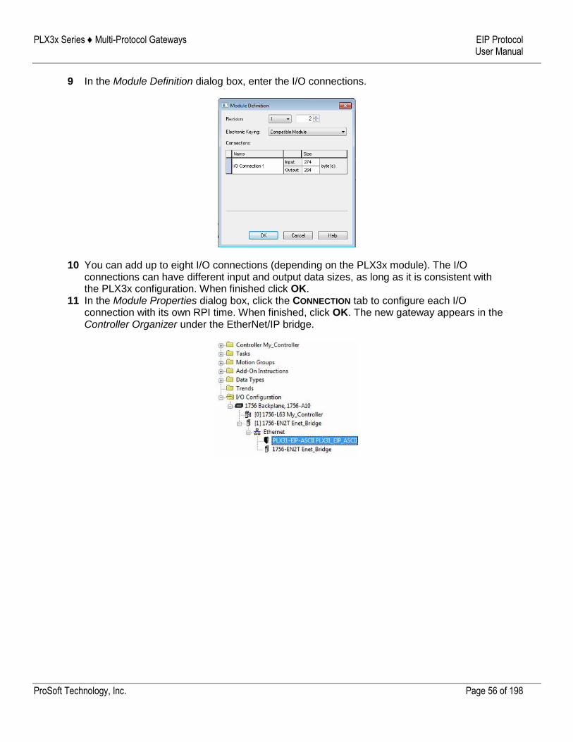
PLX3x Series ♦ Multi-Protocol Gateways EIP Protocol User Manual
ProSoft Technology, Inc. Page 56 of 198
9 In the Module Definition dialog box, enter the I/O connections.
10 You can add up to eight I/O connections (depending on the PLX3x module). The I/O connections can have different input and output data sizes, as long as it is consistent with the PLX3x configuration. When finished click OK.
11 In the Module Properties dialog box, click the CONNECTION tab to configure each I/O connection with its own RPI time. When finished, click OK. The new gateway appears in the Controller Organizer under the EtherNet/IP bridge.
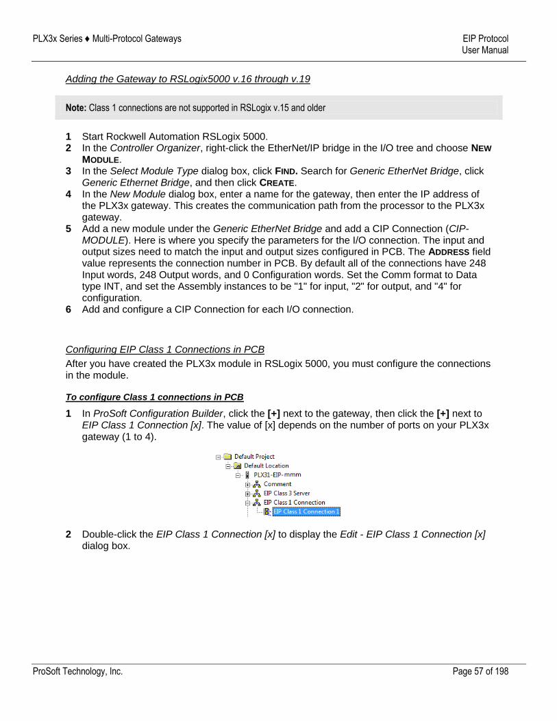
PLX3x Series ♦ Multi-Protocol Gateways EIP Protocol User Manual
ProSoft Technology, Inc. Page 57 of 198
Adding the Gateway to RSLogix5000 v.16 through v.19
Note: Class 1 connections are not supported in RSLogix v.15 and older
1 Start Rockwell Automation RSLogix 5000. 2 In the Controller Organizer, right-click the EtherNet/IP bridge in the I/O tree and choose NEW
MODULE. 3 In the Select Module Type dialog box, click FIND. Search for Generic EtherNet Bridge, click
Generic Ethernet Bridge, and then click CREATE. 4 In the New Module dialog box, enter a name for the gateway, then enter the IP address of
the PLX3x gateway. This creates the communication path from the processor to the PLX3x gateway.
5 Add a new module under the Generic EtherNet Bridge and add a CIP Connection (CIP-MODULE). Here is where you specify the parameters for the I/O connection. The input and output sizes need to match the input and output sizes configured in PCB. The ADDRESS field value represents the connection number in PCB. By default all of the connections have 248 Input words, 248 Output words, and 0 Configuration words. Set the Comm format to Data type INT, and set the Assembly instances to be "1" for input, "2" for output, and "4" for configuration.
6 Add and configure a CIP Connection for each I/O connection.
Configuring EIP Class 1 Connections in PCB
After you have created the PLX3x module in RSLogix 5000, you must configure the connections in the module.
To configure Class 1 connections in PCB
1 In ProSoft Configuration Builder, click the [+] next to the gateway, then click the [+] next to EIP Class 1 Connection [x]. The value of [x] depends on the number of ports on your PLX3x gateway (1 to 4).
2 Double-click the EIP Class 1 Connection [x] to display the Edit - EIP Class 1 Connection [x] dialog box.
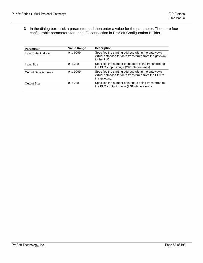
PLX3x Series ♦ Multi-Protocol Gateways EIP Protocol User Manual
ProSoft Technology, Inc. Page 58 of 198
3 In the dialog box, click a parameter and then enter a value for the parameter. There are four configurable parameters for each I/O connection in ProSoft Configuration Builder:
Parameter Value Range Description
Input Data Address 0 to 9999 Specifies the starting address within the gateway’s virtual database for data transferred from the gateway to the PLC.
Input Size 0 to 248 Specifies the number of Integers being transferred to the PLC's input image (248 integers max).
Output Data Address 0 to 9999 Specifies the starting address within the gateway’s virtual database for data transferred from the PLC to the gateway.
Output Size 0 to 248 Specifies the number of integers being transferred to the PLC's output image (248 integers max).
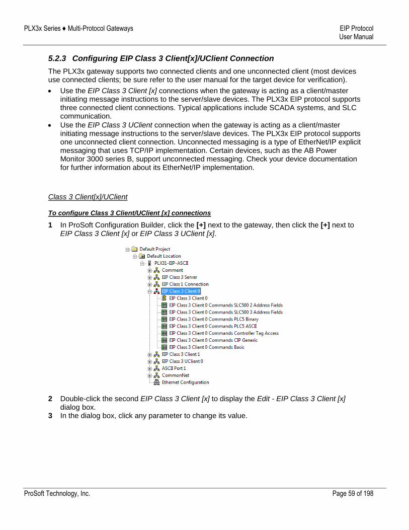
PLX3x Series ♦ Multi-Protocol Gateways EIP Protocol User Manual
ProSoft Technology, Inc. Page 59 of 198
5.2.3 Configuring EIP Class 3 Client[x]/UClient Connection
The PLX3x gateway supports two connected clients and one unconnected client (most devices use connected clients; be sure refer to the user manual for the target device for verification).
Use the EIP Class 3 Client [x] connections when the gateway is acting as a client/master initiating message instructions to the server/slave devices. The PLX3x EIP protocol supports three connected client connections. Typical applications include SCADA systems, and SLC communication.
Use the EIP Class 3 UClient connection when the gateway is acting as a client/master initiating message instructions to the server/slave devices. The PLX3x EIP protocol supports one unconnected client connection. Unconnected messaging is a type of EtherNet/IP explicit messaging that uses TCP/IP implementation. Certain devices, such as the AB Power Monitor 3000 series B, support unconnected messaging. Check your device documentation for further information about its EtherNet/IP implementation.
Class 3 Client[x]/UClient
To configure Class 3 Client/UClient [x] connections
1 In ProSoft Configuration Builder, click the [+] next to the gateway, then click the [+] next to EIP Class 3 Client [x] or EIP Class 3 UClient [x].
2 Double-click the second EIP Class 3 Client [x] to display the Edit - EIP Class 3 Client [x] dialog box.
3 In the dialog box, click any parameter to change its value.
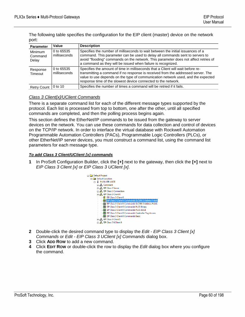
PLX3x Series ♦ Multi-Protocol Gateways EIP Protocol User Manual
ProSoft Technology, Inc. Page 60 of 198
The following table specifies the configuration for the EIP client (master) device on the network port:
Parameter Value Description
Minimum Command Delay
0 to 65535 milliseconds
Specifies the number of milliseconds to wait between the initial issuances of a command. This parameter can be used to delay all commands sent to servers to avoid "flooding" commands on the network. This parameter does not affect retries of a command as they will be issued when failure is recognized.
Response Timeout
0 to 65535 milliseconds
Specifies the amount of time in milliseconds that a Client will wait before re-transmitting a command if no response is received from the addressed server. The value to use depends on the type of communication network used, and the expected response time of the slowest device connected to the network.
Retry Count 0 to 10 Specifies the number of times a command will be retried if it fails.
Class 3 Client[x]/UClient Commands
There is a separate command list for each of the different message types supported by the protocol. Each list is processed from top to bottom, one after the other, until all specified commands are completed, and then the polling process begins again.
This section defines the EtherNet/IP commands to be issued from the gateway to server devices on the network. You can use these commands for data collection and control of devices on the TCP/IP network. In order to interface the virtual database with Rockwell Automation Programmable Automation Controllers (PACs), Programmable Logic Controllers (PLCs), or other EtherNet/IP server devices, you must construct a command list, using the command list parameters for each message type.
To add Class 3 Client/UClient [x] commands
1 In ProSoft Configuration Builder, click the [+] next to the gateway, then click the [+] next to EIP Class 3 Client [x] or EIP Class 3 UClient [x].
2 Double-click the desired command type to display the Edit - EIP Class 3 Client [x] Commands or Edit - EIP Class 3 UClient [x] Commands dialog box.
3 Click ADD ROW to add a new command. 4 Click EDIT ROW or double-click the row to display the Edit dialog box where you configure
the command.
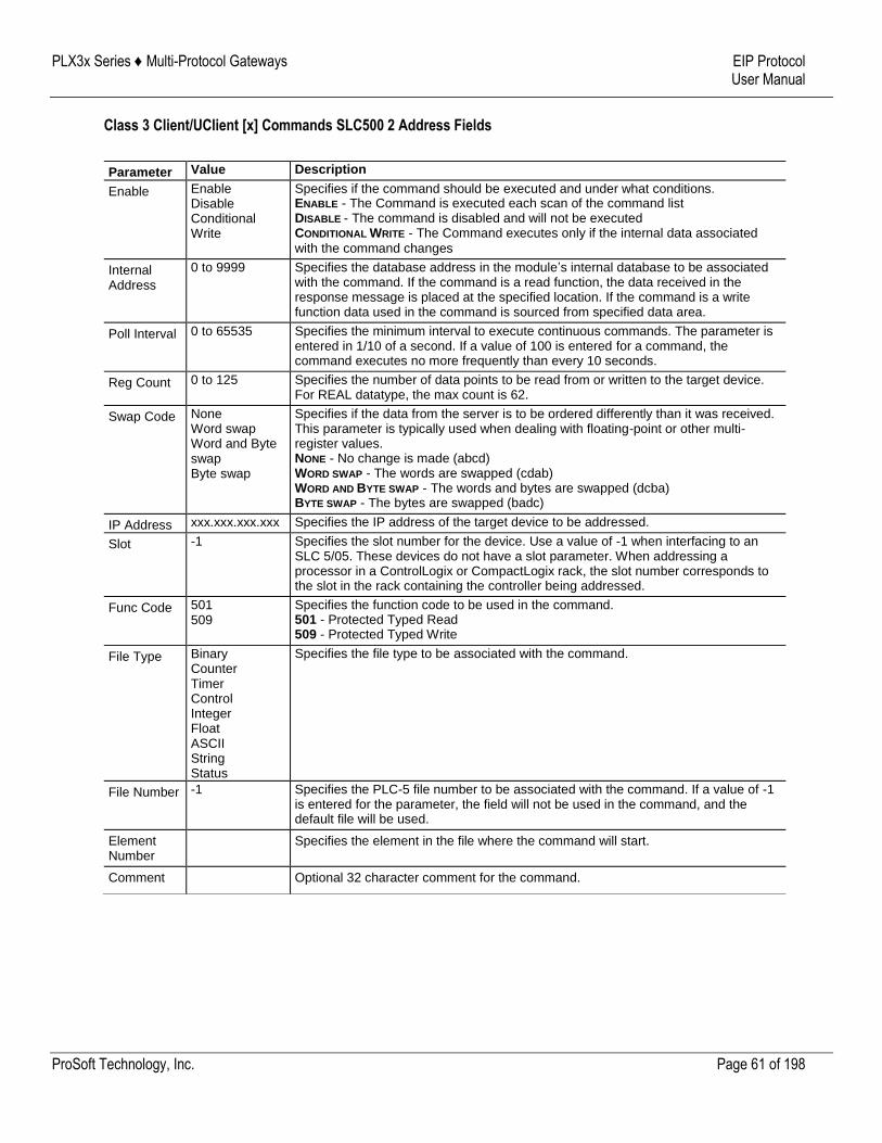
PLX3x Series ♦ Multi-Protocol Gateways EIP Protocol User Manual
ProSoft Technology, Inc. Page 61 of 198
Class 3 Client/UClient [x] Commands SLC500 2 Address Fields
Parameter Value Description
Enable Enable Disable Conditional Write
Specifies if the command should be executed and under what conditions. ENABLE - The Command is executed each scan of the command list DISABLE - The command is disabled and will not be executed CONDITIONAL WRITE - The Command executes only if the internal data associated
with the command changes
Internal Address
0 to 9999 Specifies the database address in the module’s internal database to be associated with the command. If the command is a read function, the data received in the response message is placed at the specified location. If the command is a write function data used in the command is sourced from specified data area.
Poll Interval 0 to 65535 Specifies the minimum interval to execute continuous commands. The parameter is entered in 1/10 of a second. If a value of 100 is entered for a command, the command executes no more frequently than every 10 seconds.
Reg Count 0 to 125 Specifies the number of data points to be read from or written to the target device. For REAL datatype, the max count is 62.
Swap Code None Word swap Word and Byte swap Byte swap
Specifies if the data from the server is to be ordered differently than it was received. This parameter is typically used when dealing with floating-point or other multi-register values. NONE - No change is made (abcd) WORD SWAP - The words are swapped (cdab) WORD AND BYTE SWAP - The words and bytes are swapped (dcba) BYTE SWAP - The bytes are swapped (badc)
IP Address xxx.xxx.xxx.xxx Specifies the IP address of the target device to be addressed.
Slot -1 Specifies the slot number for the device. Use a value of -1 when interfacing to an SLC 5/05. These devices do not have a slot parameter. When addressing a processor in a ControlLogix or CompactLogix rack, the slot number corresponds to the slot in the rack containing the controller being addressed.
Func Code 501 509
Specifies the function code to be used in the command. 501 - Protected Typed Read 509 - Protected Typed Write
File Type Binary Counter Timer Control Integer Float ASCII String Status
Specifies the file type to be associated with the command.
File Number -1 Specifies the PLC-5 file number to be associated with the command. If a value of -1 is entered for the parameter, the field will not be used in the command, and the default file will be used.
Element Number
Specifies the element in the file where the command will start.
Comment Optional 32 character comment for the command.
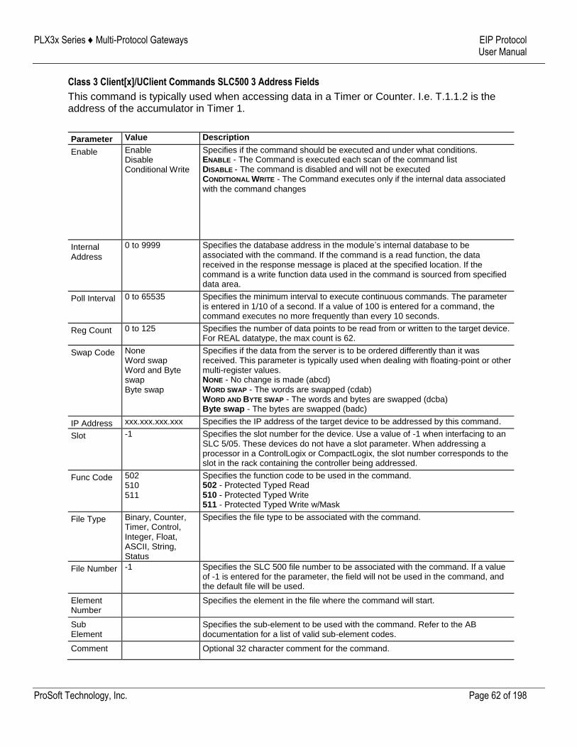
PLX3x Series ♦ Multi-Protocol Gateways EIP Protocol User Manual
ProSoft Technology, Inc. Page 62 of 198
Class 3 Client[x]/UClient Commands SLC500 3 Address Fields
This command is typically used when accessing data in a Timer or Counter. I.e. T.1.1.2 is the address of the accumulator in Timer 1.
Parameter Value Description
Enable Enable Disable Conditional Write
Specifies if the command should be executed and under what conditions. ENABLE - The Command is executed each scan of the command list DISABLE - The command is disabled and will not be executed CONDITIONAL WRITE - The Command executes only if the internal data associated
with the command changes
Internal Address
0 to 9999 Specifies the database address in the module’s internal database to be associated with the command. If the command is a read function, the data received in the response message is placed at the specified location. If the command is a write function data used in the command is sourced from specified data area.
Poll Interval 0 to 65535 Specifies the minimum interval to execute continuous commands. The parameter is entered in 1/10 of a second. If a value of 100 is entered for a command, the command executes no more frequently than every 10 seconds.
Reg Count 0 to 125 Specifies the number of data points to be read from or written to the target device. For REAL datatype, the max count is 62.
Swap Code None Word swap Word and Byte swap Byte swap
Specifies if the data from the server is to be ordered differently than it was received. This parameter is typically used when dealing with floating-point or other multi-register values. NONE - No change is made (abcd) WORD SWAP - The words are swapped (cdab) WORD AND BYTE SWAP - The words and bytes are swapped (dcba) Byte swap - The bytes are swapped (badc)
IP Address xxx.xxx.xxx.xxx Specifies the IP address of the target device to be addressed by this command.
Slot -1 Specifies the slot number for the device. Use a value of -1 when interfacing to an SLC 5/05. These devices do not have a slot parameter. When addressing a processor in a ControlLogix or CompactLogix, the slot number corresponds to the slot in the rack containing the controller being addressed.
Func Code 502 510 511
Specifies the function code to be used in the command. 502 - Protected Typed Read 510 - Protected Typed Write 511 - Protected Typed Write w/Mask
File Type Binary, Counter, Timer, Control, Integer, Float, ASCII, String, Status
Specifies the file type to be associated with the command.
File Number -1 Specifies the SLC 500 file number to be associated with the command. If a value of -1 is entered for the parameter, the field will not be used in the command, and the default file will be used.
Element Number
Specifies the element in the file where the command will start.
Sub Element
Specifies the sub-element to be used with the command. Refer to the AB documentation for a list of valid sub-element codes.
Comment Optional 32 character comment for the command.
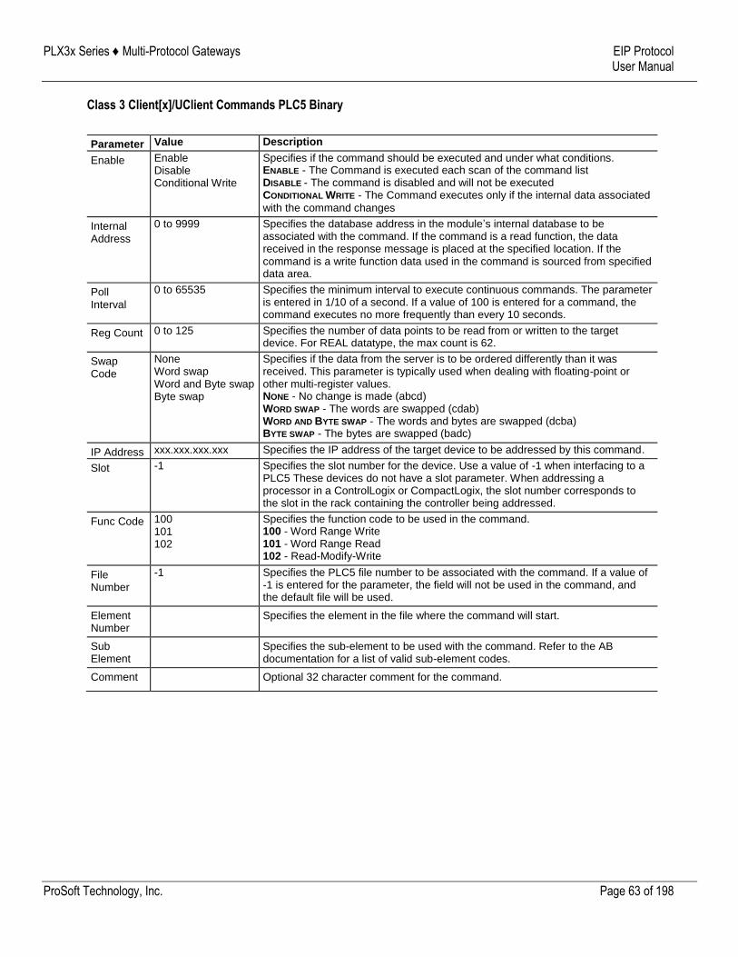
PLX3x Series ♦ Multi-Protocol Gateways EIP Protocol User Manual
ProSoft Technology, Inc. Page 63 of 198
Class 3 Client[x]/UClient Commands PLC5 Binary
Parameter Value Description
Enable Enable Disable Conditional Write
Specifies if the command should be executed and under what conditions. ENABLE - The Command is executed each scan of the command list DISABLE - The command is disabled and will not be executed CONDITIONAL WRITE - The Command executes only if the internal data associated
with the command changes
Internal Address
0 to 9999 Specifies the database address in the module’s internal database to be associated with the command. If the command is a read function, the data received in the response message is placed at the specified location. If the command is a write function data used in the command is sourced from specified data area.
Poll Interval
0 to 65535 Specifies the minimum interval to execute continuous commands. The parameter is entered in 1/10 of a second. If a value of 100 is entered for a command, the command executes no more frequently than every 10 seconds.
Reg Count 0 to 125 Specifies the number of data points to be read from or written to the target device. For REAL datatype, the max count is 62.
Swap Code
None Word swap Word and Byte swap Byte swap
Specifies if the data from the server is to be ordered differently than it was received. This parameter is typically used when dealing with floating-point or other multi-register values. NONE - No change is made (abcd) WORD SWAP - The words are swapped (cdab) WORD AND BYTE SWAP - The words and bytes are swapped (dcba) BYTE SWAP - The bytes are swapped (badc)
IP Address xxx.xxx.xxx.xxx Specifies the IP address of the target device to be addressed by this command.
Slot -1 Specifies the slot number for the device. Use a value of -1 when interfacing to a PLC5 These devices do not have a slot parameter. When addressing a processor in a ControlLogix or CompactLogix, the slot number corresponds to the slot in the rack containing the controller being addressed.
Func Code 100 101 102
Specifies the function code to be used in the command. 100 - Word Range Write 101 - Word Range Read 102 - Read-Modify-Write
File Number
-1 Specifies the PLC5 file number to be associated with the command. If a value of -1 is entered for the parameter, the field will not be used in the command, and the default file will be used.
Element Number
Specifies the element in the file where the command will start.
Sub Element
Specifies the sub-element to be used with the command. Refer to the AB documentation for a list of valid sub-element codes.
Comment Optional 32 character comment for the command.
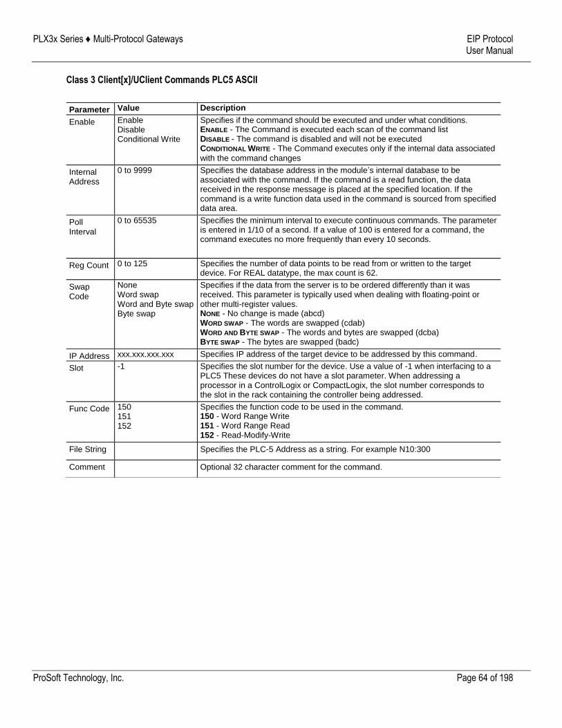
PLX3x Series ♦ Multi-Protocol Gateways EIP Protocol User Manual
ProSoft Technology, Inc. Page 64 of 198
Class 3 Client[x]/UClient Commands PLC5 ASCII
Parameter Value Description
Enable Enable Disable Conditional Write
Specifies if the command should be executed and under what conditions. ENABLE - The Command is executed each scan of the command list DISABLE - The command is disabled and will not be executed CONDITIONAL WRITE - The Command executes only if the internal data associated
with the command changes
Internal Address
0 to 9999 Specifies the database address in the module’s internal database to be associated with the command. If the command is a read function, the data received in the response message is placed at the specified location. If the command is a write function data used in the command is sourced from specified data area.
Poll Interval
0 to 65535 Specifies the minimum interval to execute continuous commands. The parameter is entered in 1/10 of a second. If a value of 100 is entered for a command, the command executes no more frequently than every 10 seconds.
Reg Count 0 to 125 Specifies the number of data points to be read from or written to the target device. For REAL datatype, the max count is 62.
Swap Code
None Word swap Word and Byte swap Byte swap
Specifies if the data from the server is to be ordered differently than it was received. This parameter is typically used when dealing with floating-point or other multi-register values. NONE - No change is made (abcd) WORD SWAP - The words are swapped (cdab) WORD AND BYTE SWAP - The words and bytes are swapped (dcba) BYTE SWAP - The bytes are swapped (badc)
IP Address xxx.xxx.xxx.xxx Specifies IP address of the target device to be addressed by this command.
Slot -1 Specifies the slot number for the device. Use a value of -1 when interfacing to a PLC5 These devices do not have a slot parameter. When addressing a processor in a ControlLogix or CompactLogix, the slot number corresponds to the slot in the rack containing the controller being addressed.
Func Code 150 151 152
Specifies the function code to be used in the command. 150 - Word Range Write 151 - Word Range Read 152 - Read-Modify-Write
File String Specifies the PLC-5 Address as a string. For example N10:300
Comment Optional 32 character comment for the command.
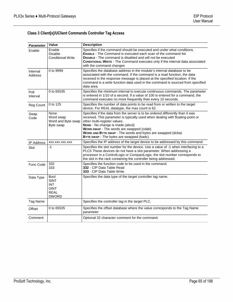
PLX3x Series ♦ Multi-Protocol Gateways EIP Protocol User Manual
ProSoft Technology, Inc. Page 65 of 198
Class 3 Client[x]/UClient Commands Controller Tag Access
Parameter Value Description
Enable Enable Disable Conditional Write
Specifies if the command should be executed and under what conditions. ENABLE - The Command is executed each scan of the command list DISABLE - The command is disabled and will not be executed CONDITIONAL WRITE - The Command executes only if the internal data associated
with the command changes
Internal Address
0 to 9999 Specifies the database address in the module’s internal database to be associated with the command. If the command is a read function, the data received in the response message is placed at the specified location. If the command is a write function data used in the command is sourced from specified data area.
Poll Interval
0 to 65535 Specifies the minimum interval to execute continuous commands. The parameter is entered in 1/10 of a second. If a value of 100 is entered for a command, the command executes no more frequently than every 10 seconds.
Reg Count 0 to 125 Specifies the number of data points to be read from or written to the target device. For REAL datatype, the max count is 62.
Swap Code
None Word swap Word and Byte swap Byte swap
Specifies if the data from the server is to be ordered differently than it was received. This parameter is typically used when dealing with floating-point or other multi-register values. NONE - No change is made (abcd) WORD SWAP - The words are swapped (cdab) WORD AND BYTE SWAP - The words and bytes are swapped (dcba) BYTE SWAP - The bytes are swapped (badc)
IP Address xxx.xxx.xxx.xxx Specifies the IP address of the target device to be addressed by this command.
Slot -1 Specifies the slot number for the device. Use a value of -1 when interfacing to a PLC5 These devices do not have a slot parameter. When addressing a processor in a ControlLogix or CompactLogix, the slot number corresponds to the slot in the rack containing the controller being addressed.
Func Code 332 333
Specifies the function code to be used in the command. 332 - CIP Data Table Read 333 - CIP Data Table Write
Data Type Bool SINT INT DINT REAL DWORD
Specifies the data type of the target controller tag name.
Tag Name Specifies the controller tag in the target PLC.
Offset 0 to 65535 Specifies the offset database where the value corresponds to the Tag Name parameter
Comment Optional 32 character comment for the command.
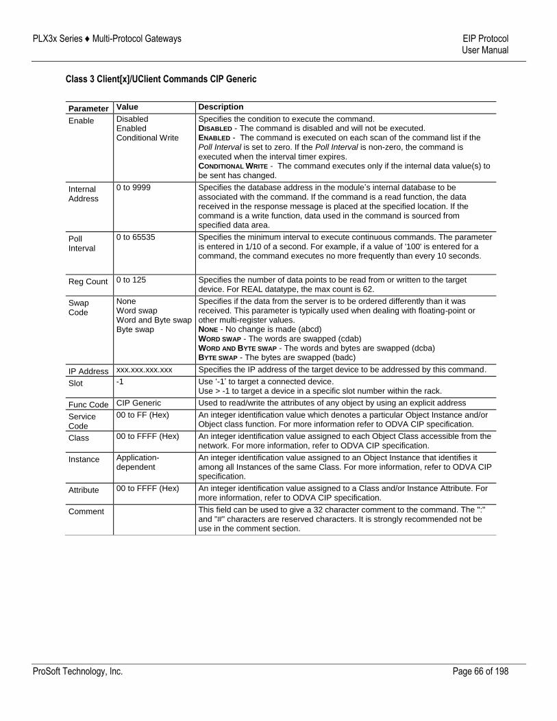
PLX3x Series ♦ Multi-Protocol Gateways EIP Protocol User Manual
ProSoft Technology, Inc. Page 66 of 198
Class 3 Client[x]/UClient Commands CIP Generic
Parameter Value Description
Enable Disabled Enabled Conditional Write
Specifies the condition to execute the command. DISABLED - The command is disabled and will not be executed. ENABLED - The command is executed on each scan of the command list if the Poll Interval is set to zero. If the Poll Interval is non-zero, the command is
executed when the interval timer expires. CONDITIONAL WRITE - The command executes only if the internal data value(s) to be sent has changed.
Internal Address
0 to 9999 Specifies the database address in the module’s internal database to be associated with the command. If the command is a read function, the data received in the response message is placed at the specified location. If the command is a write function, data used in the command is sourced from specified data area.
Poll Interval
0 to 65535 Specifies the minimum interval to execute continuous commands. The parameter is entered in 1/10 of a second. For example, if a value of '100' is entered for a command, the command executes no more frequently than every 10 seconds.
Reg Count 0 to 125 Specifies the number of data points to be read from or written to the target device. For REAL datatype, the max count is 62.
Swap Code
None Word swap Word and Byte swap Byte swap
Specifies if the data from the server is to be ordered differently than it was received. This parameter is typically used when dealing with floating-point or other multi-register values. NONE - No change is made (abcd) WORD SWAP - The words are swapped (cdab) WORD AND BYTE SWAP - The words and bytes are swapped (dcba) BYTE SWAP - The bytes are swapped (badc)
IP Address xxx.xxx.xxx.xxx Specifies the IP address of the target device to be addressed by this command.
Slot -1 Use ‘-1’ to target a connected device. Use > -1 to target a device in a specific slot number within the rack.
Func Code CIP Generic Used to read/write the attributes of any object by using an explicit address
Service Code
00 to FF (Hex) An integer identification value which denotes a particular Object Instance and/or Object class function. For more information refer to ODVA CIP specification.
Class 00 to FFFF (Hex) An integer identification value assigned to each Object Class accessible from the network. For more information, refer to ODVA CIP specification.
Instance Application-dependent
An integer identification value assigned to an Object Instance that identifies it among all Instances of the same Class. For more information, refer to ODVA CIP specification.
Attribute 00 to FFFF (Hex) An integer identification value assigned to a Class and/or Instance Attribute. For more information, refer to ODVA CIP specification.
Comment This field can be used to give a 32 character comment to the command. The ":" and "#" characters are reserved characters. It is strongly recommended not be use in the comment section.

PLX3x Series ♦ Multi-Protocol Gateways EIP Protocol User Manual
ProSoft Technology, Inc. Page 67 of 198
Note: Due to the behavior of Connected Clients, please note the following:
- You cannot configure multiple commands with different Class objects to the same device. - You cannot configure multiple commands with different Class objects to different devices.
- You can configure multiple commands using the Get_Attribute_Single of the same Class and address different Attributes. - If you have commands in any of the other command types (i.e. Controller Tag Access) and configure a CIP Generic command to the same device, it will not work due to the Connected Client having an active connection to a device. However, you can use both Controller Tag Access and CIP Generic if the target devices are different. - To avoid any or all these scenarios, it is recommended to use the Unconnected Client if you wish to send commands to different devices, since these connections are reset/closed after each command is executed.
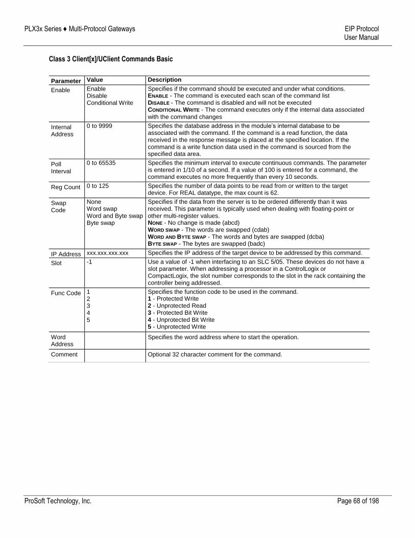
PLX3x Series ♦ Multi-Protocol Gateways EIP Protocol User Manual
ProSoft Technology, Inc. Page 68 of 198
Class 3 Client[x]/UClient Commands Basic
Parameter Value Description
Enable Enable Disable Conditional Write
Specifies if the command should be executed and under what conditions. ENABLE - The command is executed each scan of the command list DISABLE - The command is disabled and will not be executed CONDITIONAL WRITE - The command executes only if the internal data associated
with the command changes
Internal Address
0 to 9999 Specifies the database address in the module’s internal database to be associated with the command. If the command is a read function, the data received in the response message is placed at the specified location. If the command is a write function data used in the command is sourced from the specified data area.
Poll Interval
0 to 65535 Specifies the minimum interval to execute continuous commands. The parameter is entered in 1/10 of a second. If a value of 100 is entered for a command, the command executes no more frequently than every 10 seconds.
Reg Count 0 to 125 Specifies the number of data points to be read from or written to the target device. For REAL datatype, the max count is 62.
Swap Code
None Word swap Word and Byte swap Byte swap
Specifies if the data from the server is to be ordered differently than it was received. This parameter is typically used when dealing with floating-point or other multi-register values. NONE - No change is made (abcd) WORD SWAP - The words are swapped (cdab) WORD AND BYTE SWAP - The words and bytes are swapped (dcba) BYTE SWAP - The bytes are swapped (badc)
IP Address xxx.xxx.xxx.xxx Specifies the IP address of the target device to be addressed by this command.
Slot -1 Use a value of -1 when interfacing to an SLC 5/05. These devices do not have a slot parameter. When addressing a processor in a ControlLogix or CompactLogix, the slot number corresponds to the slot in the rack containing the controller being addressed.
Func Code 1 2 3 4 5
Specifies the function code to be used in the command. 1 - Protected Write 2 - Unprotected Read 3 - Protected Bit Write 4 - Unprotected Bit Write 5 - Unprotected Write
Word Address
Specifies the word address where to start the operation.
Comment Optional 32 character comment for the command.
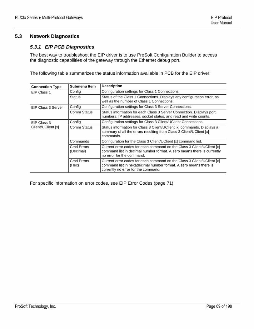
PLX3x Series ♦ Multi-Protocol Gateways EIP Protocol User Manual
ProSoft Technology, Inc. Page 69 of 198
5.3 Network Diagnostics
5.3.1 EIP PCB Diagnostics
The best way to troubleshoot the EIP driver is to use ProSoft Configuration Builder to access the diagnostic capabilities of the gateway through the Ethernet debug port.
The following table summarizes the status information available in PCB for the EIP driver:
Connection Type Submenu Item Description
EIP Class 1 Config Configuration settings for Class 1 Connections.
Status Status of the Class 1 Connections. Displays any configuration error, as well as the number of Class 1 Connections.
EIP Class 3 Server Config Configuration settings for Class 3 Server Connections.
Comm Status Status information for each Class 3 Server Connection. Displays port numbers, IP addresses, socket status, and read and write counts.
EIP Class 3 Client/UClient [x]
Config Configuration settings for Class 3 Client/UClient Connections.
Comm Status Status information for Class 3 Client/UClient [x] commands. Displays a summary of all the errors resulting from Class 3 Client/UClient [x] commands.
Commands Configuration for the Class 3 Client/UClient [x] command list.
Cmd Errors (Decimal)
Current error codes for each command on the Class 3 Client/UClient [x] command list in decimal number format. A zero means there is currently no error for the command.
Cmd Errors (Hex)
Current error codes for each command on the Class 3 Client/UClient [x] command list in hexadecimal number format. A zero means there is currently no error for the command.
For specific information on error codes, see EIP Error Codes (page 71).
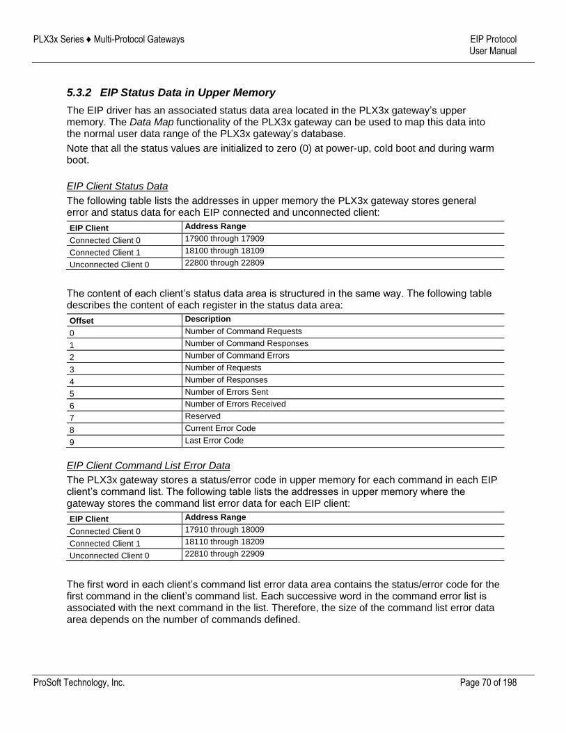
PLX3x Series ♦ Multi-Protocol Gateways EIP Protocol User Manual
ProSoft Technology, Inc. Page 70 of 198
5.3.2 EIP Status Data in Upper Memory
The EIP driver has an associated status data area located in the PLX3x gateway’s upper memory. The Data Map functionality of the PLX3x gateway can be used to map this data into the normal user data range of the PLX3x gateway’s database.
Note that all the status values are initialized to zero (0) at power-up, cold boot and during warm boot.
EIP Client Status Data
The following table lists the addresses in upper memory the PLX3x gateway stores general error and status data for each EIP connected and unconnected client:
EIP Client Address Range
Connected Client 0 17900 through 17909
Connected Client 1 18100 through 18109
Unconnected Client 0 22800 through 22809
The content of each client’s status data area is structured in the same way. The following table describes the content of each register in the status data area:
Offset Description
0 Number of Command Requests
1 Number of Command Responses
2 Number of Command Errors
3 Number of Requests
4 Number of Responses
5 Number of Errors Sent
6 Number of Errors Received
7 Reserved
8 Current Error Code
9 Last Error Code
EIP Client Command List Error Data
The PLX3x gateway stores a status/error code in upper memory for each command in each EIP client’s command list. The following table lists the addresses in upper memory where the gateway stores the command list error data for each EIP client:
EIP Client Address Range
Connected Client 0 17910 through 18009
Connected Client 1 18110 through 18209
Unconnected Client 0 22810 through 22909
The first word in each client’s command list error data area contains the status/error code for the first command in the client’s command list. Each successive word in the command error list is associated with the next command in the list. Therefore, the size of the command list error data area depends on the number of commands defined.
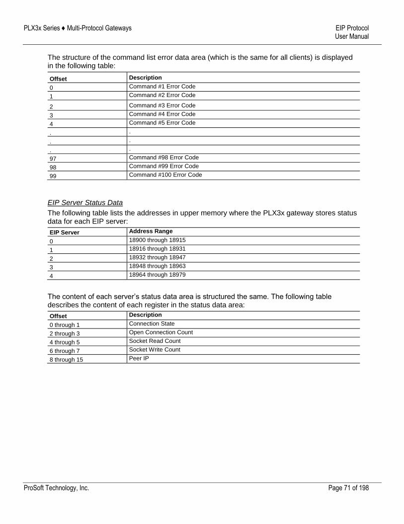
PLX3x Series ♦ Multi-Protocol Gateways EIP Protocol User Manual
ProSoft Technology, Inc. Page 71 of 198
The structure of the command list error data area (which is the same for all clients) is displayed in the following table:
Offset Description
0 Command #1 Error Code
1 Command #2 Error Code
2 Command #3 Error Code
3 Command #4 Error Code
4 Command #5 Error Code
. .
. .
. .
97 Command #98 Error Code
98 Command #99 Error Code
99 Command #100 Error Code
EIP Server Status Data
The following table lists the addresses in upper memory where the PLX3x gateway stores status data for each EIP server:
EIP Server Address Range
0 18900 through 18915
1 18916 through 18931
2 18932 through 18947
3 18948 through 18963
4 18964 through 18979
The content of each server’s status data area is structured the same. The following table describes the content of each register in the status data area:
Offset Description
0 through 1 Connection State
2 through 3 Open Connection Count
4 through 5 Socket Read Count
6 through 7 Socket Write Count
8 through 15 Peer IP
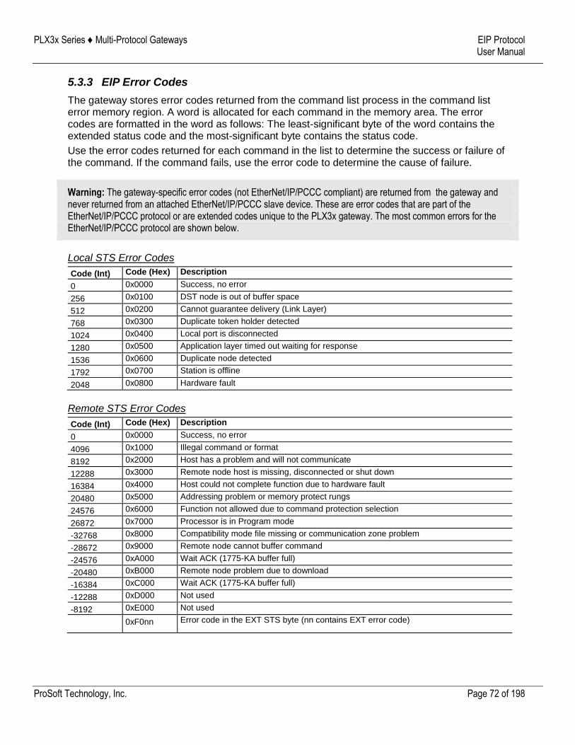
PLX3x Series ♦ Multi-Protocol Gateways EIP Protocol User Manual
ProSoft Technology, Inc. Page 72 of 198
5.3.3 EIP Error Codes
The gateway stores error codes returned from the command list process in the command list error memory region. A word is allocated for each command in the memory area. The error codes are formatted in the word as follows: The least-significant byte of the word contains the extended status code and the most-significant byte contains the status code.
Use the error codes returned for each command in the list to determine the success or failure of the command. If the command fails, use the error code to determine the cause of failure.
Warning: The gateway-specific error codes (not EtherNet/IP/PCCC compliant) are returned from the gateway and never returned from an attached EtherNet/IP/PCCC slave device. These are error codes that are part of the EtherNet/IP/PCCC protocol or are extended codes unique to the PLX3x gateway. The most common errors for the EtherNet/IP/PCCC protocol are shown below.
Local STS Error Codes
Code (Int) Code (Hex) Description
0 0x0000 Success, no error
256 0x0100 DST node is out of buffer space
512 0x0200 Cannot guarantee delivery (Link Layer)
768 0x0300 Duplicate token holder detected
1024 0x0400 Local port is disconnected
1280 0x0500 Application layer timed out waiting for response
1536 0x0600 Duplicate node detected
1792 0x0700 Station is offline
2048 0x0800 Hardware fault
Remote STS Error Codes
Code (Int) Code (Hex) Description
0 0x0000 Success, no error
4096 0x1000 Illegal command or format
8192 0x2000 Host has a problem and will not communicate
12288 0x3000 Remote node host is missing, disconnected or shut down
16384 0x4000 Host could not complete function due to hardware fault
20480 0x5000 Addressing problem or memory protect rungs
24576 0x6000 Function not allowed due to command protection selection
26872 0x7000 Processor is in Program mode
-32768 0x8000 Compatibility mode file missing or communication zone problem
-28672 0x9000 Remote node cannot buffer command
-24576 0xA000 Wait ACK (1775-KA buffer full)
-20480 0xB000 Remote node problem due to download
-16384 0xC000 Wait ACK (1775-KA buffer full)
-12288 0xD000 Not used
-8192 0xE000 Not used
0xF0nn Error code in the EXT STS byte (nn contains EXT error code)
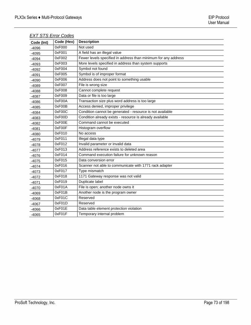
PLX3x Series ♦ Multi-Protocol Gateways EIP Protocol User Manual
ProSoft Technology, Inc. Page 73 of 198
EXT STS Error Codes
Code (Int) Code (Hex) Description
-4096 0xF000 Not used
-4095 0xF001 A field has an illegal value
-4094 0xF002 Fewer levels specified in address than minimum for any address
-4093 0xF003 More levels specified in address than system supports
-4092 0xF004 Symbol not found
-4091 0xF005 Symbol is of improper format
-4090 0xF006 Address does not point to something usable
-4089 0xF007 File is wrong size
-4088 0xF008 Cannot complete request
-4087 0xF009 Data or file is too large
-4086 0xF00A Transaction size plus word address is too large
-4085 0xF00B Access denied, improper privilege
-4084 0xF00C Condition cannot be generated - resource is not available
-4083 0xF00D Condition already exists - resource is already available
-4082 0xF00E Command cannot be executed
-4081 0xF00F Histogram overflow
-4080 0xF010 No access
-4079 0xF011 Illegal data type
-4078 0xF012 Invalid parameter or invalid data
-4077 0xF013 Address reference exists to deleted area
-4076 0xF014 Command execution failure for unknown reason
-4075 0xF015 Data conversion error
-4074 0xF016 Scanner not able to communicate with 1771 rack adapter
-4073 0xF017 Type mismatch
-4072 0xF018 1171 Gateway response was not valid
-4071 0xF019 Duplicate label
-4070 0xF01A File is open; another node owns it
-4069 0xF01B Another node is the program owner
-4068 0xF01C Reserved
-4067 0xF01D Reserved
-4066 0xF01E Data table element protection violation
-4065 0xF01F Temporary internal problem
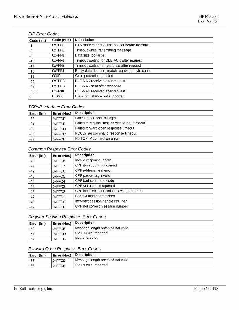
PLX3x Series ♦ Multi-Protocol Gateways EIP Protocol User Manual
ProSoft Technology, Inc. Page 74 of 198
EIP Error Codes
Code (Int) Code (Hex) Description
-1 0xFFFF CTS modem control line not set before transmit
-2 0xFFFE Timeout while transmitting message
-8 0xFFF8 Data size too large
-10 0xFFF6 Timeout waiting for DLE-ACK after request
-11 0xFFF5 Timeout waiting for response after request
-12 0xFFF4 Reply data does not match requested byte count
-15 000F Write protection enabled
-20 0xFFEC DLE-NAK received after request
-21 0xFFEB DLE-NAK sent after response
-200 0xFF38 DLE-NAK received after request
5 0x0005 Class or instance not supported
TCP/IP Interface Error Codes
Error (Int) Error (Hex) Description
-33 0xFFDF Failed to connect to target
-34 0xFFDE Failed to register session with target (timeout)
-35 0xFFDD Failed forward open response timeout
-36 0xFFDC PCCC/Tag command response timeout
-37 0xFFDB No TCP/IP connection error
Common Response Error Codes
Error (Int) Error (Hex) Description
-40 0xFFD8 Invalid response length
-41 0xFFD7 CPF item count not correct
-42 0xFFD6 CPF address field error
-43 0xFFD5 CPF packet tag invalid
-44 0xFFD4 CPF bad command code
-45 0xFFD3 CPF status error reported
-46 0xFFD2 CPF incorrect connection ID value returned
-47 0xFFD1 Context field not matched
-48 0xFFD0 Incorrect session handle returned
-49 0xFFCF CPF not correct message number
Register Session Response Error Codes
Error (Int) Error (Hex) Description
-50 0xFFCE Message length received not valid
-51 0xFFCD Status error reported
-52 0xFFCC Invalid version
Forward Open Response Error Codes
Error (Int) Error (Hex) Description
-55 0xFFC9 Message length received not valid
-56 0xFFC8 Status error reported
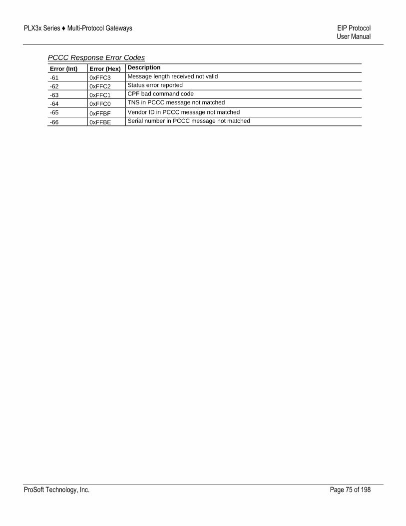
PLX3x Series ♦ Multi-Protocol Gateways EIP Protocol User Manual
ProSoft Technology, Inc. Page 75 of 198
PCCC Response Error Codes
Error (Int) Error (Hex) Description
-61 0xFFC3 Message length received not valid
-62 0xFFC2 Status error reported
-63 0xFFC1 CPF bad command code
-64 0xFFC0 TNS in PCCC message not matched
-65 0xFFBF Vendor ID in PCCC message not matched
-66 0xFFBE Serial number in PCCC message not matched
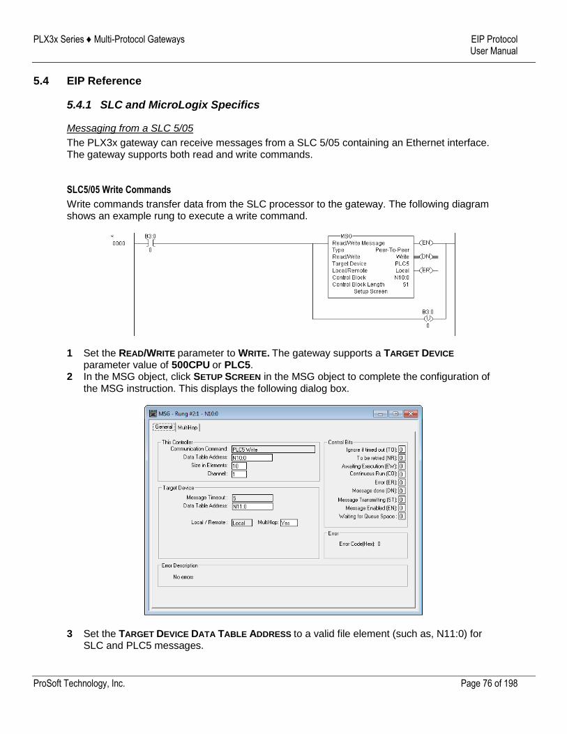
PLX3x Series ♦ Multi-Protocol Gateways EIP Protocol User Manual
ProSoft Technology, Inc. Page 76 of 198
5.4 EIP Reference
5.4.1 SLC and MicroLogix Specifics
Messaging from a SLC 5/05
The PLX3x gateway can receive messages from a SLC 5/05 containing an Ethernet interface. The gateway supports both read and write commands.
SLC5/05 Write Commands
Write commands transfer data from the SLC processor to the gateway. The following diagram shows an example rung to execute a write command.
1 Set the READ/WRITE parameter to WRITE. The gateway supports a TARGET DEVICE parameter value of 500CPU or PLC5.
2 In the MSG object, click SETUP SCREEN in the MSG object to complete the configuration of the MSG instruction. This displays the following dialog box.
3 Set the TARGET DEVICE DATA TABLE ADDRESS to a valid file element (such as, N11:0) for SLC and PLC5 messages.
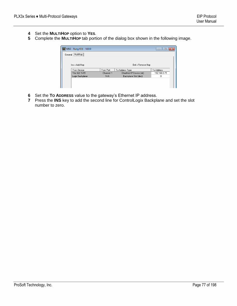
PLX3x Series ♦ Multi-Protocol Gateways EIP Protocol User Manual
ProSoft Technology, Inc. Page 77 of 198
4 Set the MULTIHOP option to YES. 5 Complete the MULTIHOP tab portion of the dialog box shown in the following image.
6 Set the TO ADDRESS value to the gateway’s Ethernet IP address. 7 Press the INS key to add the second line for ControlLogix Backplane and set the slot
number to zero.

PLX3x Series ♦ Multi-Protocol Gateways EIP Protocol User Manual
ProSoft Technology, Inc. Page 78 of 198
SLC5/05 Read Commands
Read commands transfer data to the SLC processor from the gateway. The following diagram shows an example rung to execute a read command.
1 Set the READ/WRITE parameter to READ. The gateway supports a TARGET DEVICE parameter value of 500CPU or PLC5.
2 In the MSG object, click SETUP SCREEN in the MSG object to complete the configuration of the MSG instruction. This displays the following dialog box.
3 Set the TARGET DEVICE DATA TABLE ADDRESS to a valid file element (such as, N11:0) for SLC and PLC5 messages.
4 Set the MULTIHOP option to YES.
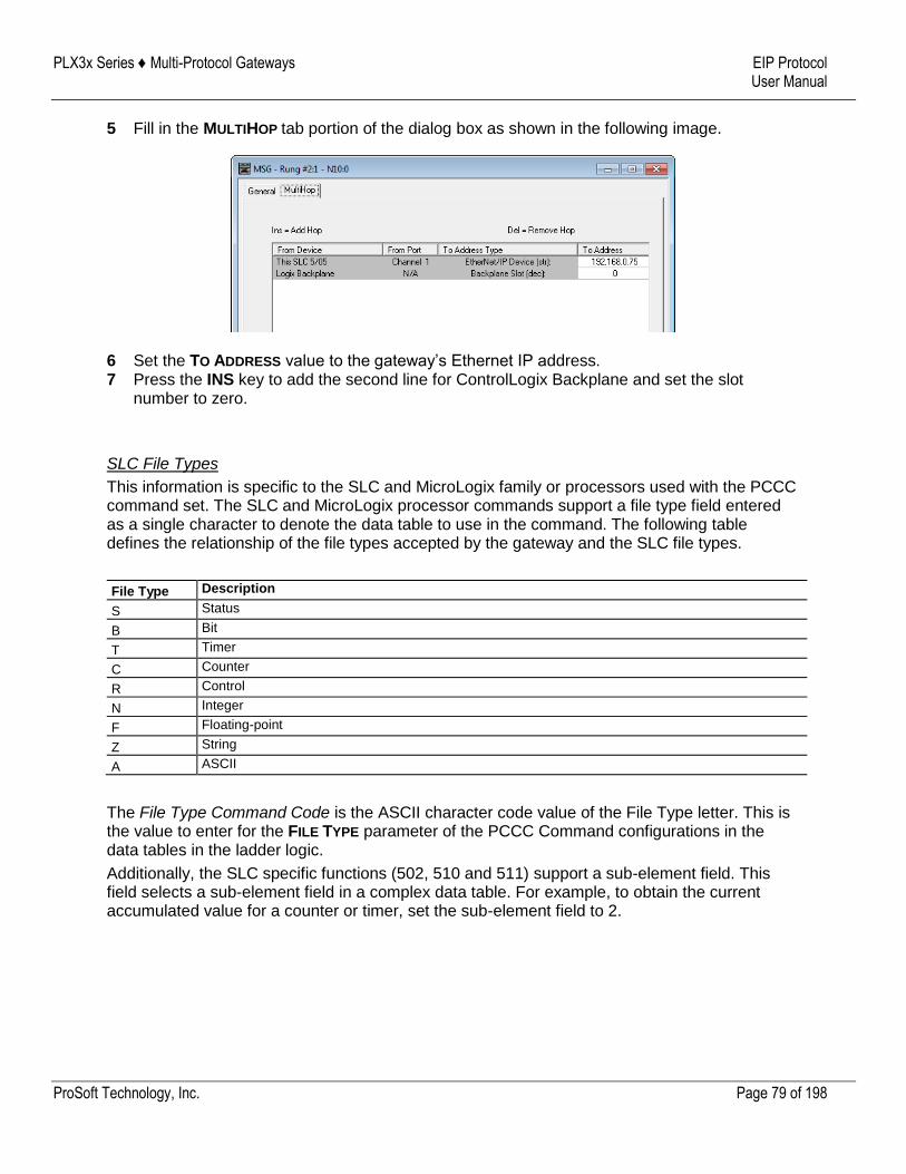
PLX3x Series ♦ Multi-Protocol Gateways EIP Protocol User Manual
ProSoft Technology, Inc. Page 79 of 198
5 Fill in the MULTIHOP tab portion of the dialog box as shown in the following image.
6 Set the TO ADDRESS value to the gateway’s Ethernet IP address. 7 Press the INS key to add the second line for ControlLogix Backplane and set the slot
number to zero.
SLC File Types
This information is specific to the SLC and MicroLogix family or processors used with the PCCC command set. The SLC and MicroLogix processor commands support a file type field entered as a single character to denote the data table to use in the command. The following table defines the relationship of the file types accepted by the gateway and the SLC file types.
File Type Description
S Status
B Bit
T Timer
C Counter
R Control
N Integer
F Floating-point
Z String
A ASCII
The File Type Command Code is the ASCII character code value of the File Type letter. This is the value to enter for the FILE TYPE parameter of the PCCC Command configurations in the data tables in the ladder logic.
Additionally, the SLC specific functions (502, 510 and 511) support a sub-element field. This field selects a sub-element field in a complex data table. For example, to obtain the current accumulated value for a counter or timer, set the sub-element field to 2.
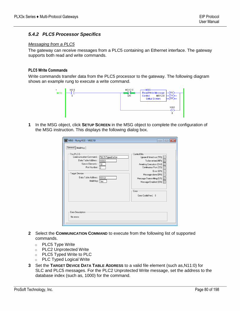
PLX3x Series ♦ Multi-Protocol Gateways EIP Protocol User Manual
ProSoft Technology, Inc. Page 80 of 198
5.4.2 PLC5 Processor Specifics
Messaging from a PLC5
The gateway can receive messages from a PLC5 containing an Ethernet interface. The gateway supports both read and write commands.
PLC5 Write Commands
Write commands transfer data from the PLC5 processor to the gateway. The following diagram shows an example rung to execute a write command.
1 In the MSG object, click SETUP SCREEN in the MSG object to complete the configuration of the MSG instruction. This displays the following dialog box.
2 Select the COMMUNICATION COMMAND to execute from the following list of supported commands.
o PLC5 Type Write o PLC2 Unprotected Write o PLC5 Typed Write to PLC o PLC Typed Logical Write
3 Set the TARGET DEVICE DATA TABLE ADDRESS to a valid file element (such as,N11:0) for SLC and PLC5 messages. For the PLC2 Unprotected Write message, set the address to the database index (such as, 1000) for the command.
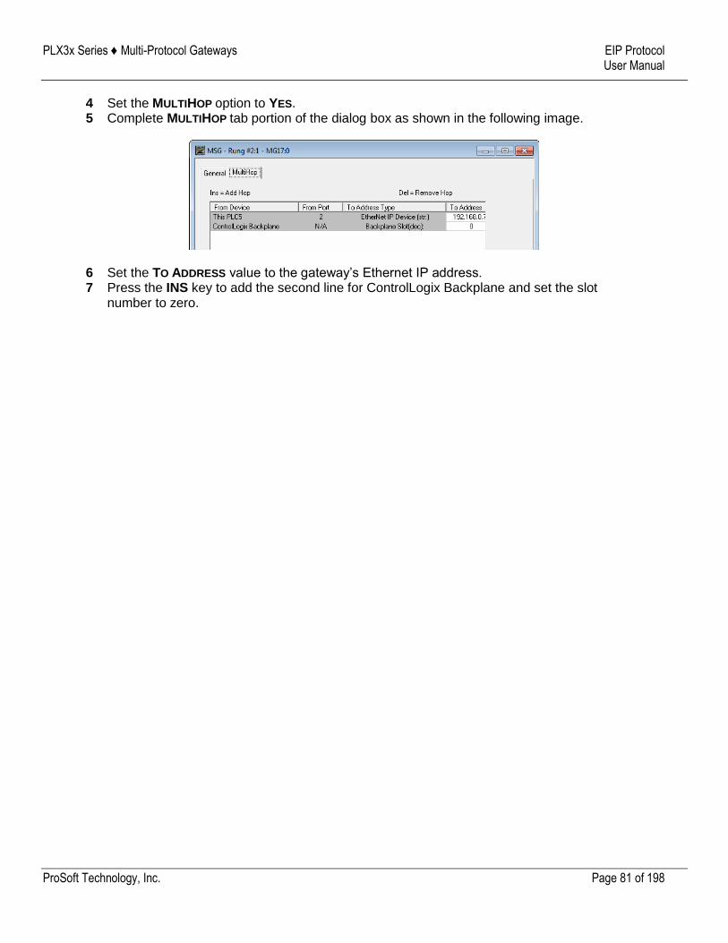
PLX3x Series ♦ Multi-Protocol Gateways EIP Protocol User Manual
ProSoft Technology, Inc. Page 81 of 198
4 Set the MULTIHOP option to YES. 5 Complete MULTIHOP tab portion of the dialog box as shown in the following image.
6 Set the TO ADDRESS value to the gateway’s Ethernet IP address. 7 Press the INS key to add the second line for ControlLogix Backplane and set the slot
number to zero.
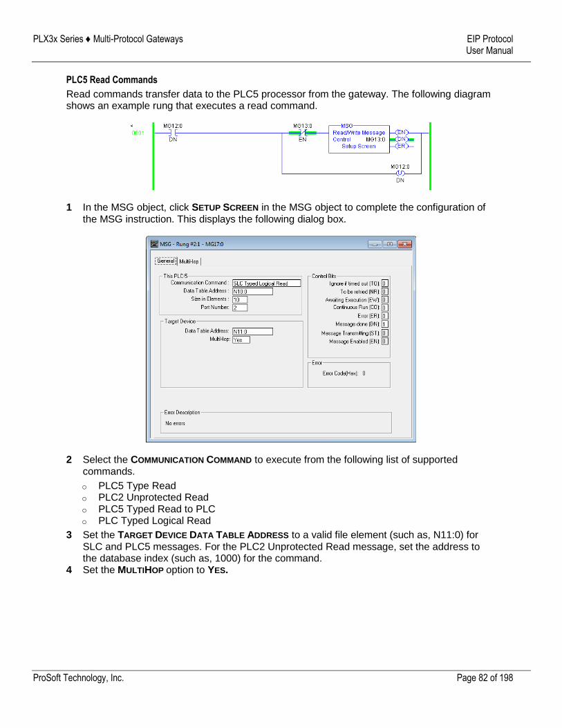
PLX3x Series ♦ Multi-Protocol Gateways EIP Protocol User Manual
ProSoft Technology, Inc. Page 82 of 198
PLC5 Read Commands
Read commands transfer data to the PLC5 processor from the gateway. The following diagram shows an example rung that executes a read command.
1 In the MSG object, click SETUP SCREEN in the MSG object to complete the configuration of the MSG instruction. This displays the following dialog box.
2 Select the COMMUNICATION COMMAND to execute from the following list of supported commands.
o PLC5 Type Read o PLC2 Unprotected Read o PLC5 Typed Read to PLC o PLC Typed Logical Read
3 Set the TARGET DEVICE DATA TABLE ADDRESS to a valid file element (such as, N11:0) for SLC and PLC5 messages. For the PLC2 Unprotected Read message, set the address to the database index (such as, 1000) for the command.
4 Set the MULTIHOP option to YES.
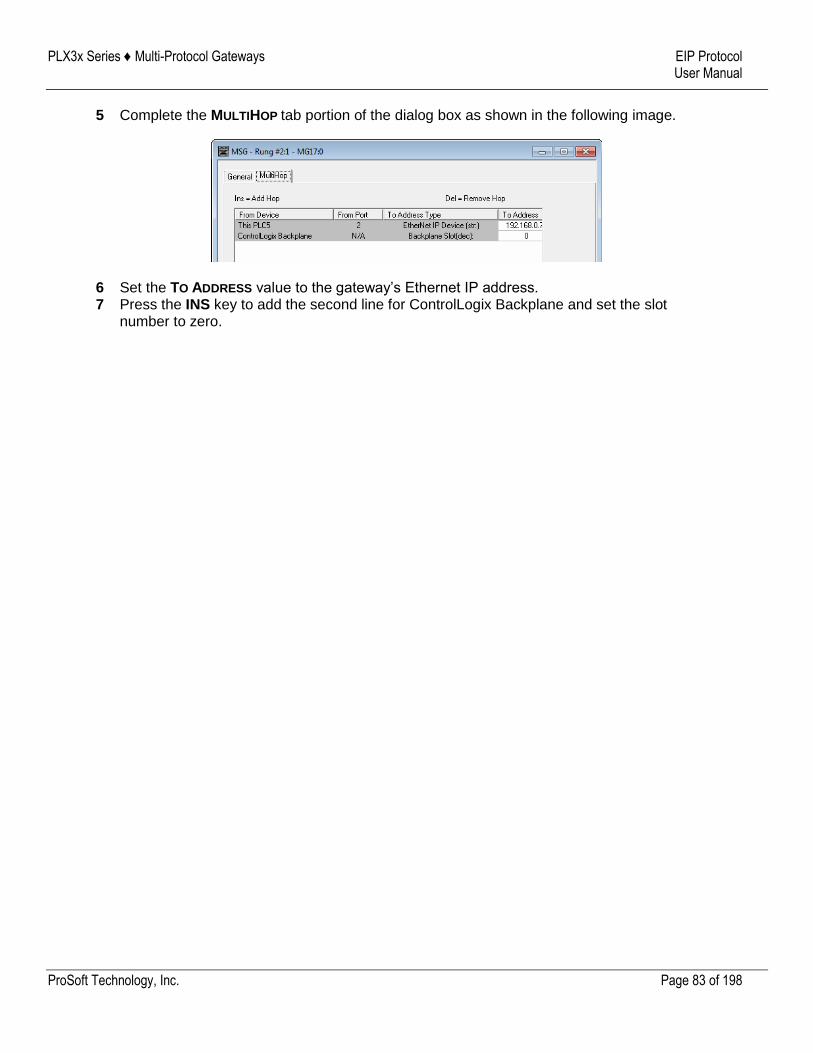
PLX3x Series ♦ Multi-Protocol Gateways EIP Protocol User Manual
ProSoft Technology, Inc. Page 83 of 198
5 Complete the MULTIHOP tab portion of the dialog box as shown in the following image.
6 Set the TO ADDRESS value to the gateway’s Ethernet IP address. 7 Press the INS key to add the second line for ControlLogix Backplane and set the slot
number to zero.

PLX3x Series ♦ Multi-Protocol Gateways EIP Protocol User Manual
ProSoft Technology, Inc. Page 84 of 198
PLC-5 Sub-Element Fields
This section contains information specific to the PLC-5 processor when using the PCCC command set. The commands specific to the PLC-5 processor contain a sub-element code field. This field selects a sub-element field in a complex data table. For example, to obtain the current accumulated value for a counter or timer, set the sub-element field to 2. The following tables show the sub-element codes for PLC-5 complex data tables.
Timer / Counter
Code Description
0 Control
1 Preset
2 Accumulated
Control
Code Description
0 Control
1 Length
2 Position
PD
All PD values are floating point values, they are two words long.
Code Description
0 Control
2 SP
4 Kp
6 Ki
8 Kd
26 PV
BT
Code Description
0 Control
1 RLEN
2 DLEN
3 Data file #
4 Element #
5 Rack/Grp/Slot
MG
Code Description
0 Control
1 Error
2 RLEN
3 DLEN
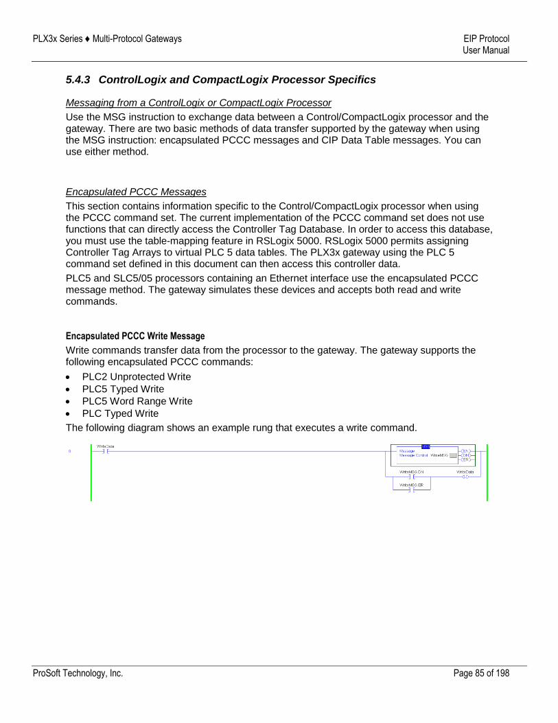
PLX3x Series ♦ Multi-Protocol Gateways EIP Protocol User Manual
ProSoft Technology, Inc. Page 85 of 198
5.4.3 ControlLogix and CompactLogix Processor Specifics
Messaging from a ControlLogix or CompactLogix Processor
Use the MSG instruction to exchange data between a Control/CompactLogix processor and the gateway. There are two basic methods of data transfer supported by the gateway when using the MSG instruction: encapsulated PCCC messages and CIP Data Table messages. You can use either method.
Encapsulated PCCC Messages
This section contains information specific to the Control/CompactLogix processor when using the PCCC command set. The current implementation of the PCCC command set does not use functions that can directly access the Controller Tag Database. In order to access this database, you must use the table-mapping feature in RSLogix 5000. RSLogix 5000 permits assigning Controller Tag Arrays to virtual PLC 5 data tables. The PLX3x gateway using the PLC 5 command set defined in this document can then access this controller data.
PLC5 and SLC5/05 processors containing an Ethernet interface use the encapsulated PCCC message method. The gateway simulates these devices and accepts both read and write commands.
Encapsulated PCCC Write Message
Write commands transfer data from the processor to the gateway. The gateway supports the following encapsulated PCCC commands:
PLC2 Unprotected Write
PLC5 Typed Write
PLC5 Word Range Write
PLC Typed Write
The following diagram shows an example rung that executes a write command.
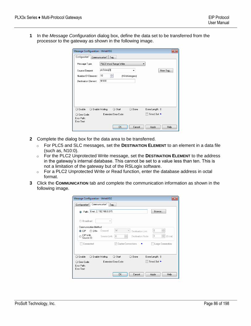
PLX3x Series ♦ Multi-Protocol Gateways EIP Protocol User Manual
ProSoft Technology, Inc. Page 86 of 198
1 In the Message Configuration dialog box, define the data set to be transferred from the processor to the gateway as shown in the following image.
2 Complete the dialog box for the data area to be transferred.
o For PLC5 and SLC messages, set the DESTINATION ELEMENT to an element in a data file (such as, N10:0).
o For the PLC2 Unprotected Write message, set the DESTINATION ELEMENT to the address in the gateway’s internal database. This cannot be set to a value less than ten. This is not a limitation of the gateway but of the RSLogix software.
o For a PLC2 Unprotected Write or Read function, enter the database address in octal format.
3 Click the COMMUNICATION tab and complete the communication information as shown in the following image.
PLX3x Series ♦ Multi-Protocol Gateways EIP Protocol User Manual
ProSoft Technology, Inc. Page 87 of 198
4 Make sure you select CIP as the COMMUNICATION METHOD. The PATH specifies the message route from the processor to the EIP gateway. Path elements are separated by commas. In the example path shown:
o The first element is "Enet", which is the user-defined name given to the 1756-ENET gateway in the chassis (you can substitute the slot number of the ENET gateway for the name)
o The second element, "2", represents the Ethernet port on the 1756-ENET gateway. o The last element of the path, "192.168.0.75" is the IP address of the gateway, which is
the target for the message.
More complex paths are possible if routing to other networks using multiple 1756-ENET gateways and racks. Refer to the ProSoft Technology Technical Support Knowledgebase for more information on Ethernet routing and path definitions (www.prosoft-technology.com/support).
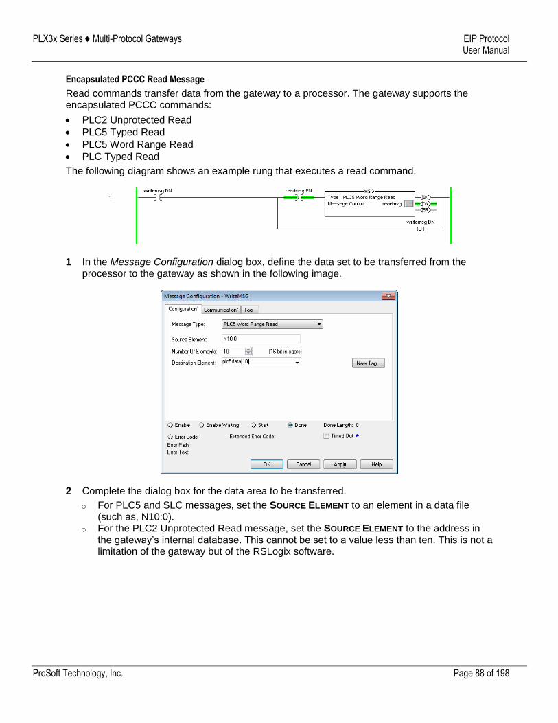
PLX3x Series ♦ Multi-Protocol Gateways EIP Protocol User Manual
ProSoft Technology, Inc. Page 88 of 198
Encapsulated PCCC Read Message
Read commands transfer data from the gateway to a processor. The gateway supports the encapsulated PCCC commands:
PLC2 Unprotected Read
PLC5 Typed Read
PLC5 Word Range Read
PLC Typed Read
The following diagram shows an example rung that executes a read command.
1 In the Message Configuration dialog box, define the data set to be transferred from the processor to the gateway as shown in the following image.
2 Complete the dialog box for the data area to be transferred.
o For PLC5 and SLC messages, set the SOURCE ELEMENT to an element in a data file (such as, N10:0).
o For the PLC2 Unprotected Read message, set the SOURCE ELEMENT to the address in the gateway’s internal database. This cannot be set to a value less than ten. This is not a limitation of the gateway but of the RSLogix software.
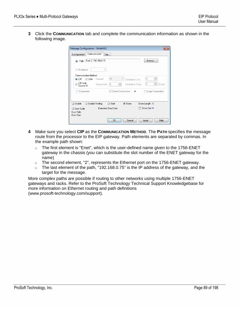
PLX3x Series ♦ Multi-Protocol Gateways EIP Protocol User Manual
ProSoft Technology, Inc. Page 89 of 198
3 Click the COMMUNICATION tab and complete the communication information as shown in the following image.
4 Make sure you select CIP as the COMMUNICATION METHOD. The PATH specifies the message route from the processor to the EIP gateway. Path elements are separated by commas. In the example path shown:
o The first element is "Enet", which is the user-defined name given to the 1756-ENET gateway in the chassis (you can substitute the slot number of the ENET gateway for the name)
o The second element, "2", represents the Ethernet port on the 1756-ENET gateway. o The last element of the path, "192.168.0.75" is the IP address of the gateway, and the
target for the message.
More complex paths are possible if routing to other networks using multiple 1756-ENET gateways and racks. Refer to the ProSoft Technology Technical Support Knowledgebase for more information on Ethernet routing and path definitions (www.prosoft-technology.com/support).
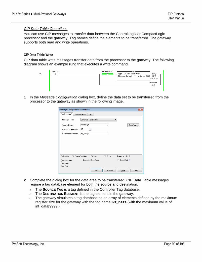
PLX3x Series ♦ Multi-Protocol Gateways EIP Protocol User Manual
ProSoft Technology, Inc. Page 90 of 198
CIP Data Table Operations
You can use CIP messages to transfer data between the ControlLogix or CompactLogix processor and the gateway. Tag names define the elements to be transferred. The gateway supports both read and write operations.
CIP Data Table Write
CIP data table write messages transfer data from the processor to the gateway. The following diagram shows an example rung that executes a write command.
1 In the Message Configuration dialog box, define the data set to be transferred from the processor to the gateway as shown in the following image.
2 Complete the dialog box for the data area to be transferred. CIP Data Table messages require a tag database element for both the source and destination.
o The SOURCE TAG is a tag defined in the Controller Tag database. o The DESTINATION ELEMENT is the tag element in the gateway. o The gateway simulates a tag database as an array of elements defined by the maximum
register size for the gateway with the tag name INT_DATA (with the maximum value of int_data[9999]).
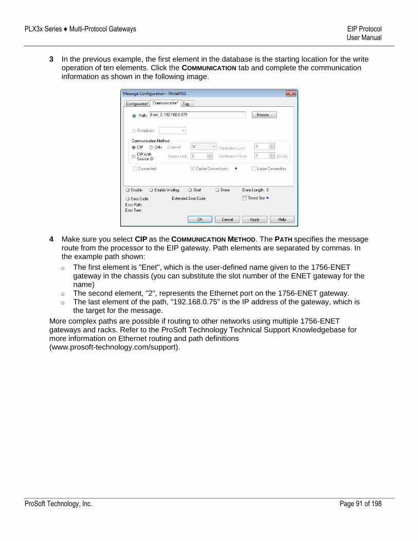
PLX3x Series ♦ Multi-Protocol Gateways EIP Protocol User Manual
ProSoft Technology, Inc. Page 91 of 198
3 In the previous example, the first element in the database is the starting location for the write operation of ten elements. Click the COMMUNICATION tab and complete the communication information as shown in the following image.
4 Make sure you select CIP as the COMMUNICATION METHOD. The PATH specifies the message route from the processor to the EIP gateway. Path elements are separated by commas. In the example path shown:
o The first element is "Enet", which is the user-defined name given to the 1756-ENET gateway in the chassis (you can substitute the slot number of the ENET gateway for the name)
o The second element, "2", represents the Ethernet port on the 1756-ENET gateway. o The last element of the path, "192.168.0.75" is the IP address of the gateway, which is
the target for the message.
More complex paths are possible if routing to other networks using multiple 1756-ENET gateways and racks. Refer to the ProSoft Technology Technical Support Knowledgebase for more information on Ethernet routing and path definitions (www.prosoft-technology.com/support).
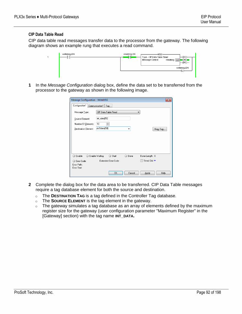
PLX3x Series ♦ Multi-Protocol Gateways EIP Protocol User Manual
ProSoft Technology, Inc. Page 92 of 198
CIP Data Table Read
CIP data table read messages transfer data to the processor from the gateway. The following diagram shows an example rung that executes a read command.
1 In the Message Configuration dialog box, define the data set to be transferred from the processor to the gateway as shown in the following image.
2 Complete the dialog box for the data area to be transferred. CIP Data Table messages require a tag database element for both the source and destination.
o The DESTINATION TAG is a tag defined in the Controller Tag database. o The SOURCE ELEMENT is the tag element in the gateway. o The gateway simulates a tag database as an array of elements defined by the maximum
register size for the gateway (user configuration parameter "Maximum Register" in the [Gateway] section) with the tag name INT_DATA.

PLX3x Series ♦ Multi-Protocol Gateways EIP Protocol User Manual
ProSoft Technology, Inc. Page 93 of 198
3 In the previous example, the first element in the database is the starting location for the read operation of ten elements. Click the COMMUNICATION tab and complete the communication information as shown in the following image.
4 Make sure you select CIP as the COMMUNICATION METHOD. The PATH specifies the message route from the processor to the EIP gateway. Path elements are separated by commas. In the example path shown:
o The first element is "Enet", which is the user-defined name given to the 1756-ENET gateway in the chassis (you can substitute the slot number of the ENET gateway for the name)
o The second element, "2", represents the Ethernet port on the 1756-ENET gateway. o The last element of the path, "192.168.0.75" is the IP address of the gateway, which is
the target for the message.
More complex paths are possible if routing to other networks using multiple 1756-ENET gateways and racks. Refer to the ProSoft Technology Technical Support Knowledgebase for more information on Ethernet routing and path definitions (www.prosoft-technology.com/support).
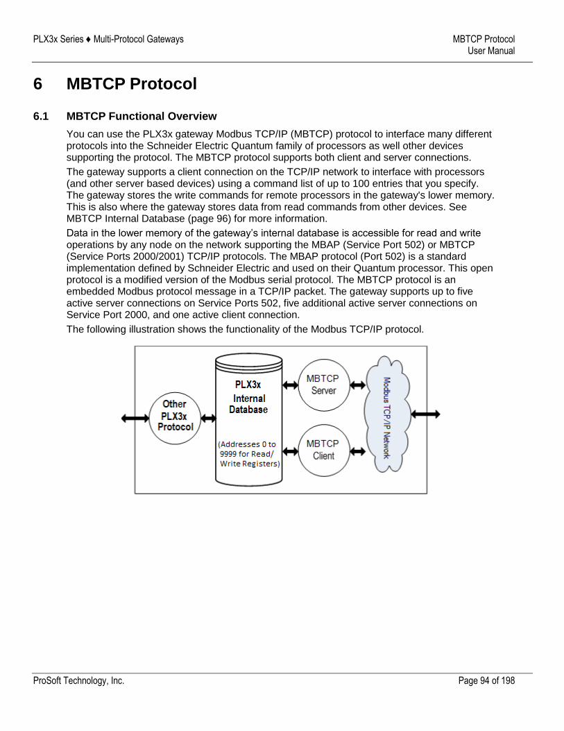
PLX3x Series ♦ Multi-Protocol Gateways MBTCP Protocol User Manual
ProSoft Technology, Inc. Page 94 of 198
6 MBTCP Protocol
6.1 MBTCP Functional Overview
You can use the PLX3x gateway Modbus TCP/IP (MBTCP) protocol to interface many different protocols into the Schneider Electric Quantum family of processors as well other devices supporting the protocol. The MBTCP protocol supports both client and server connections.
The gateway supports a client connection on the TCP/IP network to interface with processors (and other server based devices) using a command list of up to 100 entries that you specify. The gateway stores the write commands for remote processors in the gateway's lower memory. This is also where the gateway stores data from read commands from other devices. See MBTCP Internal Database (page 96) for more information.
Data in the lower memory of the gateway’s internal database is accessible for read and write operations by any node on the network supporting the MBAP (Service Port 502) or MBTCP (Service Ports 2000/2001) TCP/IP protocols. The MBAP protocol (Port 502) is a standard implementation defined by Schneider Electric and used on their Quantum processor. This open protocol is a modified version of the Modbus serial protocol. The MBTCP protocol is an embedded Modbus protocol message in a TCP/IP packet. The gateway supports up to five active server connections on Service Ports 502, five additional active server connections on Service Port 2000, and one active client connection.
The following illustration shows the functionality of the Modbus TCP/IP protocol.
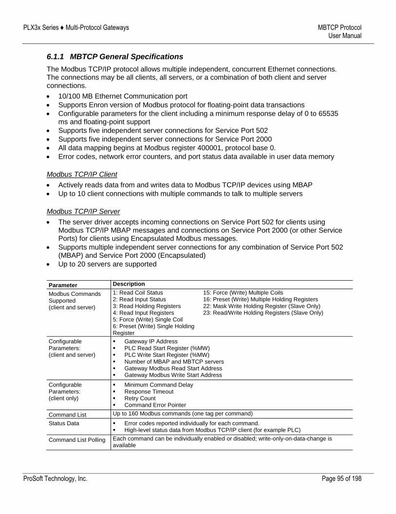
PLX3x Series ♦ Multi-Protocol Gateways MBTCP Protocol User Manual
ProSoft Technology, Inc. Page 95 of 198
6.1.1 MBTCP General Specifications
The Modbus TCP/IP protocol allows multiple independent, concurrent Ethernet connections. The connections may be all clients, all servers, or a combination of both client and server connections.
10/100 MB Ethernet Communication port
Supports Enron version of Modbus protocol for floating-point data transactions
Configurable parameters for the client including a minimum response delay of 0 to 65535 ms and floating-point support
Supports five independent server connections for Service Port 502
Supports five independent server connections for Service Port 2000
All data mapping begins at Modbus register 400001, protocol base 0.
Error codes, network error counters, and port status data available in user data memory
Modbus TCP/IP Client
Actively reads data from and writes data to Modbus TCP/IP devices using MBAP
Up to 10 client connections with multiple commands to talk to multiple servers
Modbus TCP/IP Server
The server driver accepts incoming connections on Service Port 502 for clients using Modbus TCP/IP MBAP messages and connections on Service Port 2000 (or other Service Ports) for clients using Encapsulated Modbus messages.
Supports multiple independent server connections for any combination of Service Port 502 (MBAP) and Service Port 2000 (Encapsulated)
Up to 20 servers are supported
Parameter Description
Modbus Commands Supported (client and server)
1: Read Coil Status 2: Read Input Status 3: Read Holding Registers 4: Read Input Registers 5: Force (Write) Single Coil 6: Preset (Write) Single Holding Register
15: Force (Write) Multiple Coils 16: Preset (Write) Multiple Holding Registers 22: Mask Write Holding Register (Slave Only) 23: Read/Write Holding Registers (Slave Only)
Configurable Parameters: (client and server)
Gateway IP Address PLC Read Start Register (%MW) PLC Write Start Register (%MW) Number of MBAP and MBTCP servers Gateway Modbus Read Start Address Gateway Modbus Write Start Address
Configurable Parameters: (client only)
Minimum Command Delay Response Timeout Retry Count Command Error Pointer
Command List Up to 160 Modbus commands (one tag per command)
Status Data Error codes reported individually for each command. High-level status data from Modbus TCP/IP client (for example PLC)
Command List Polling Each command can be individually enabled or disabled; write-only-on-data-change is available
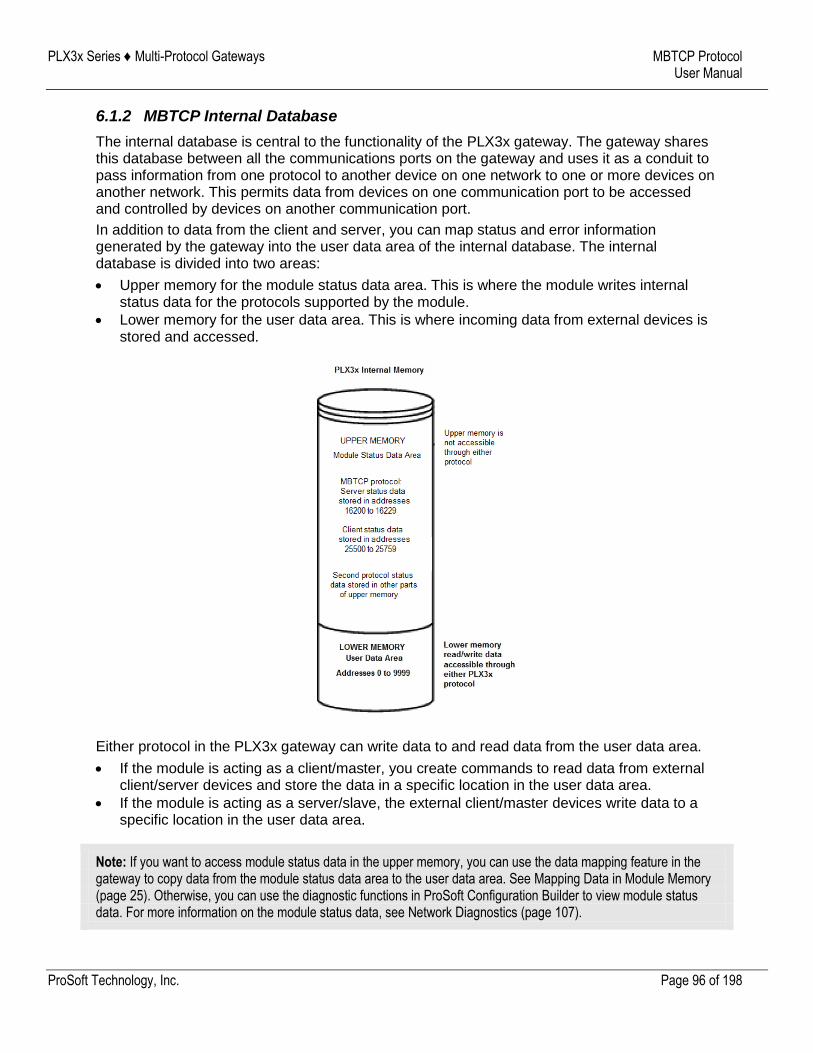
PLX3x Series ♦ Multi-Protocol Gateways MBTCP Protocol User Manual
ProSoft Technology, Inc. Page 96 of 198
6.1.2 MBTCP Internal Database
The internal database is central to the functionality of the PLX3x gateway. The gateway shares this database between all the communications ports on the gateway and uses it as a conduit to pass information from one protocol to another device on one network to one or more devices on another network. This permits data from devices on one communication port to be accessed and controlled by devices on another communication port.
In addition to data from the client and server, you can map status and error information generated by the gateway into the user data area of the internal database. The internal database is divided into two areas:
Upper memory for the module status data area. This is where the module writes internal status data for the protocols supported by the module.
Lower memory for the user data area. This is where incoming data from external devices is stored and accessed.
Either protocol in the PLX3x gateway can write data to and read data from the user data area.
If the module is acting as a client/master, you create commands to read data from external client/server devices and store the data in a specific location in the user data area.
If the module is acting as a server/slave, the external client/master devices write data to a specific location in the user data area.
Note: If you want to access module status data in the upper memory, you can use the data mapping feature in the gateway to copy data from the module status data area to the user data area. See Mapping Data in Module Memory (page 25). Otherwise, you can use the diagnostic functions in ProSoft Configuration Builder to view module status data. For more information on the module status data, see Network Diagnostics (page 107).
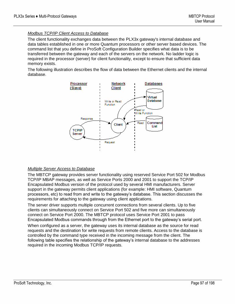
PLX3x Series ♦ Multi-Protocol Gateways MBTCP Protocol User Manual
ProSoft Technology, Inc. Page 97 of 198
Modbus TCP/IP Client Access to Database
The client functionality exchanges data between the PLX3x gateway's internal database and data tables established in one or more Quantum processors or other server based devices. The command list that you define in ProSoft Configuration Builder specifies what data is to be transferred between the gateway and each of the servers on the network. No ladder logic is required in the processor (server) for client functionality, except to ensure that sufficient data memory exists.
The following illustration describes the flow of data between the Ethernet clients and the internal database.
Multiple Server Access to Database
The MBTCP gateway provides server functionality using reserved Service Port 502 for Modbus TCP/IP MBAP messages, as well as Service Ports 2000 and 2001 to support the TCP/IP Encapsulated Modbus version of the protocol used by several HMI manufacturers. Server support in the gateway permits client applications (for example: HMI software, Quantum processors, etc) to read from and write to the gateway’s database. This section discusses the requirements for attaching to the gateway using client applications.
The server driver supports multiple concurrent connections from several clients. Up to five clients can simultaneously connect on Service Port 502 and five more can simultaneously connect on Service Port 2000. The MBTCP protocol uses Service Port 2001 to pass Encapsulated Modbus commands through from the Ethernet port to the gateway’s serial port.
When configured as a server, the gateway uses its internal database as the source for read requests and the destination for write requests from remote clients. Access to the database is controlled by the command type received in the incoming message from the client. The following table specifies the relationship of the gateway’s internal database to the addresses required in the incoming Modbus TCP/IP requests.
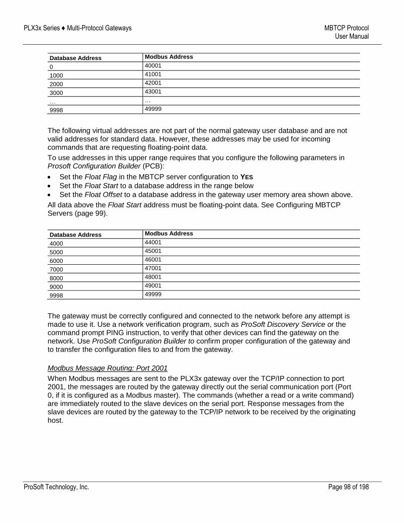
PLX3x Series ♦ Multi-Protocol Gateways MBTCP Protocol User Manual
ProSoft Technology, Inc. Page 98 of 198
Database Address Modbus Address
0 40001
1000 41001
2000 42001
3000 43001
… …
9998 49999
The following virtual addresses are not part of the normal gateway user database and are not valid addresses for standard data. However, these addresses may be used for incoming commands that are requesting floating-point data.
To use addresses in this upper range requires that you configure the following parameters in Prosoft Configuration Builder (PCB):
Set the Float Flag in the MBTCP server configuration to YES
Set the Float Start to a database address in the range below
Set the Float Offset to a database address in the gateway user memory area shown above.
All data above the Float Start address must be floating-point data. See Configuring MBTCP Servers (page 99).
Database Address Modbus Address
4000 44001
5000 45001
6000 46001
7000 47001
8000 48001
9000 49001
9998 49999
The gateway must be correctly configured and connected to the network before any attempt is made to use it. Use a network verification program, such as ProSoft Discovery Service or the command prompt PING instruction, to verify that other devices can find the gateway on the network. Use ProSoft Configuration Builder to confirm proper configuration of the gateway and to transfer the configuration files to and from the gateway.
Modbus Message Routing: Port 2001
When Modbus messages are sent to the PLX3x gateway over the TCP/IP connection to port 2001, the messages are routed by the gateway directly out the serial communication port (Port 0, if it is configured as a Modbus master). The commands (whether a read or a write command) are immediately routed to the slave devices on the serial port. Response messages from the slave devices are routed by the gateway to the TCP/IP network to be received by the originating host.
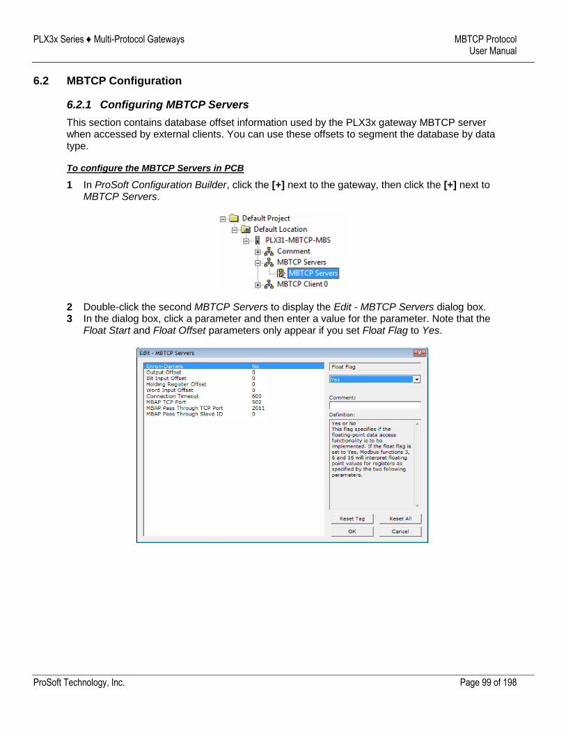
PLX3x Series ♦ Multi-Protocol Gateways MBTCP Protocol User Manual
ProSoft Technology, Inc. Page 99 of 198
6.2 MBTCP Configuration
6.2.1 Configuring MBTCP Servers
This section contains database offset information used by the PLX3x gateway MBTCP server when accessed by external clients. You can use these offsets to segment the database by data type.
To configure the MBTCP Servers in PCB
1 In ProSoft Configuration Builder, click the [+] next to the gateway, then click the [+] next to MBTCP Servers.
2 Double-click the second MBTCP Servers to display the Edit - MBTCP Servers dialog box. 3 In the dialog box, click a parameter and then enter a value for the parameter. Note that the
Float Start and Float Offset parameters only appear if you set Float Flag to Yes.
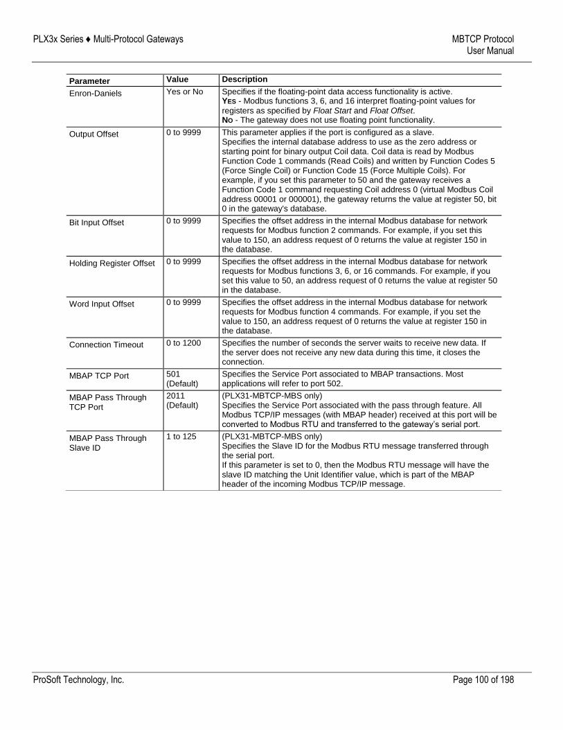
PLX3x Series ♦ Multi-Protocol Gateways MBTCP Protocol User Manual
ProSoft Technology, Inc. Page 100 of 198
Parameter Value Description
Enron-Daniels Yes or No Specifies if the floating-point data access functionality is active. YES - Modbus functions 3, 6, and 16 interpret floating-point values for
registers as specified by Float Start and Float Offset. NO - The gateway does not use floating point functionality.
Output Offset 0 to 9999 This parameter applies if the port is configured as a slave. Specifies the internal database address to use as the zero address or starting point for binary output Coil data. Coil data is read by Modbus Function Code 1 commands (Read Coils) and written by Function Codes 5 (Force Single Coil) or Function Code 15 (Force Multiple Coils). For example, if you set this parameter to 50 and the gateway receives a Function Code 1 command requesting Coil address 0 (virtual Modbus Coil address 00001 or 000001), the gateway returns the value at register 50, bit 0 in the gateway's database.
Bit Input Offset 0 to 9999 Specifies the offset address in the internal Modbus database for network requests for Modbus function 2 commands. For example, if you set this value to 150, an address request of 0 returns the value at register 150 in the database.
Holding Register Offset 0 to 9999 Specifies the offset address in the internal Modbus database for network requests for Modbus functions 3, 6, or 16 commands. For example, if you set this value to 50, an address request of 0 returns the value at register 50 in the database.
Word Input Offset 0 to 9999 Specifies the offset address in the internal Modbus database for network requests for Modbus function 4 commands. For example, if you set the value to 150, an address request of 0 returns the value at register 150 in the database.
Connection Timeout 0 to 1200 Specifies the number of seconds the server waits to receive new data. If the server does not receive any new data during this time, it closes the connection.
MBAP TCP Port 501 (Default)
Specifies the Service Port associated to MBAP transactions. Most applications will refer to port 502.
MBAP Pass Through TCP Port
2011 (Default)
(PLX31-MBTCP-MBS only) Specifies the Service Port associated with the pass through feature. All Modbus TCP/IP messages (with MBAP header) received at this port will be converted to Modbus RTU and transferred to the gateway’s serial port.
MBAP Pass Through Slave ID
1 to 125 (PLX31-MBTCP-MBS only) Specifies the Slave ID for the Modbus RTU message transferred through the serial port. If this parameter is set to 0, then the Modbus RTU message will have the slave ID matching the Unit Identifier value, which is part of the MBAP header of the incoming Modbus TCP/IP message.
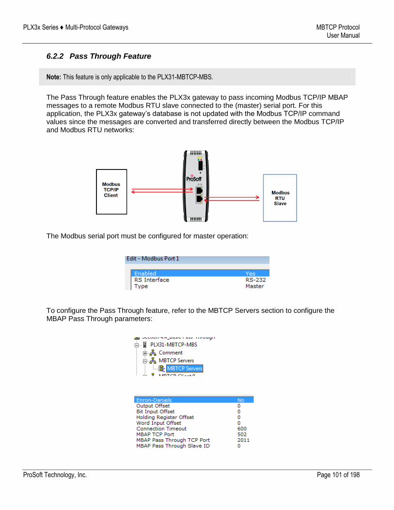
PLX3x Series ♦ Multi-Protocol Gateways MBTCP Protocol User Manual
ProSoft Technology, Inc. Page 101 of 198
6.2.2 Pass Through Feature
Note: This feature is only applicable to the PLX31-MBTCP-MBS.
The Pass Through feature enables the PLX3x gateway to pass incoming Modbus TCP/IP MBAP messages to a remote Modbus RTU slave connected to the (master) serial port. For this application, the PLX3x gateway’s database is not updated with the Modbus TCP/IP command values since the messages are converted and transferred directly between the Modbus TCP/IP and Modbus RTU networks:
The Modbus serial port must be configured for master operation:
To configure the Pass Through feature, refer to the MBTCP Servers section to configure the MBAP Pass Through parameters:
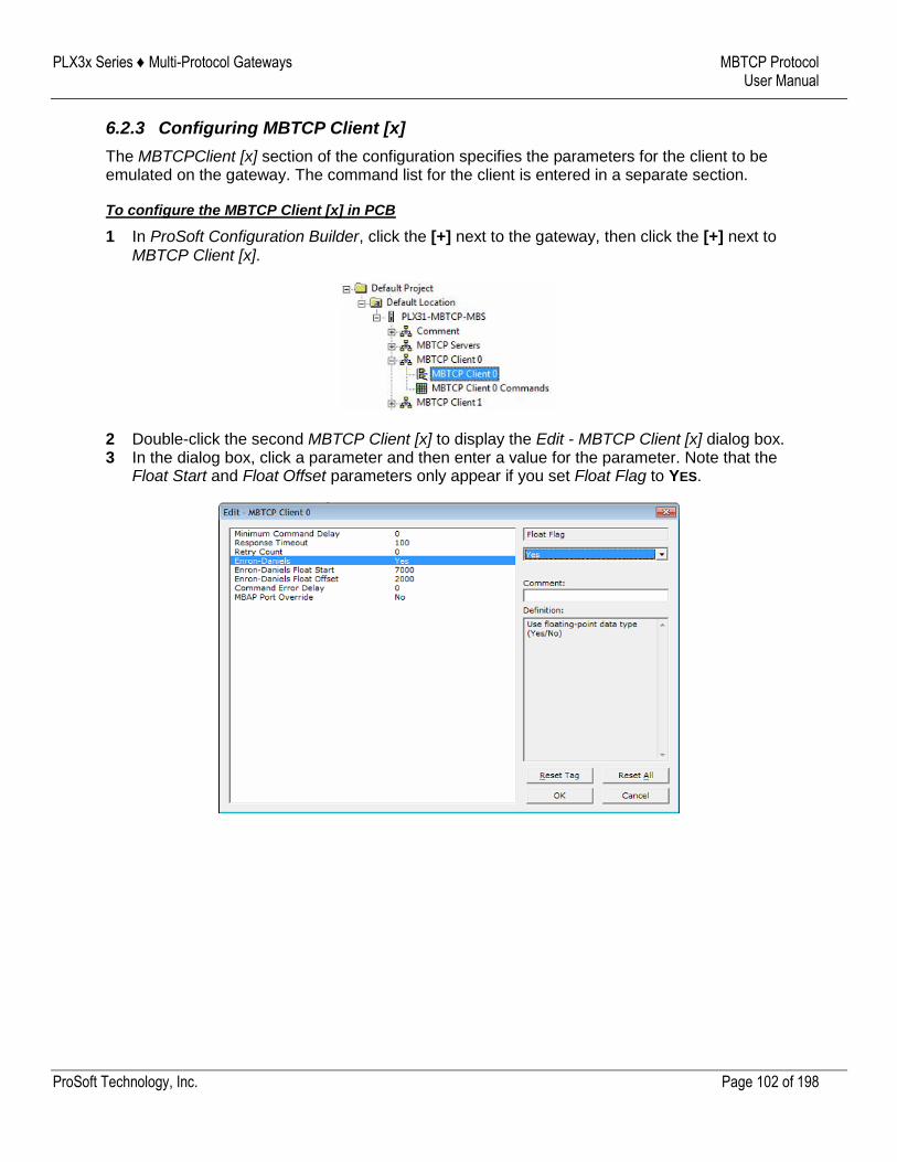
PLX3x Series ♦ Multi-Protocol Gateways MBTCP Protocol User Manual
ProSoft Technology, Inc. Page 102 of 198
6.2.3 Configuring MBTCP Client [x]
The MBTCPClient [x] section of the configuration specifies the parameters for the client to be emulated on the gateway. The command list for the client is entered in a separate section.
To configure the MBTCP Client [x] in PCB
1 In ProSoft Configuration Builder, click the [+] next to the gateway, then click the [+] next to MBTCP Client [x].
2 Double-click the second MBTCP Client [x] to display the Edit - MBTCP Client [x] dialog box. 3 In the dialog box, click a parameter and then enter a value for the parameter. Note that the
Float Start and Float Offset parameters only appear if you set Float Flag to YES.
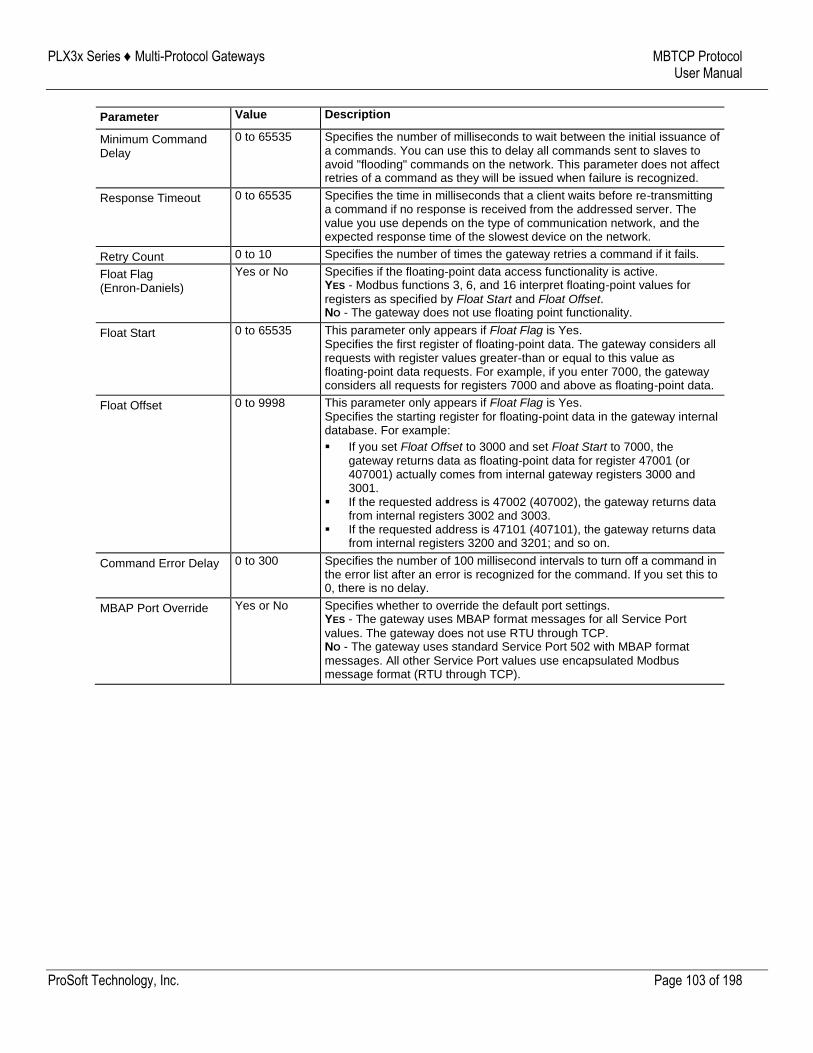
PLX3x Series ♦ Multi-Protocol Gateways MBTCP Protocol User Manual
ProSoft Technology, Inc. Page 103 of 198
Parameter Value Description
Minimum Command Delay
0 to 65535 Specifies the number of milliseconds to wait between the initial issuance of a commands. You can use this to delay all commands sent to slaves to avoid "flooding" commands on the network. This parameter does not affect retries of a command as they will be issued when failure is recognized.
Response Timeout 0 to 65535 Specifies the time in milliseconds that a client waits before re-transmitting a command if no response is received from the addressed server. The value you use depends on the type of communication network, and the expected response time of the slowest device on the network.
Retry Count 0 to 10 Specifies the number of times the gateway retries a command if it fails.
Float Flag (Enron-Daniels)
Yes or No Specifies if the floating-point data access functionality is active. YES - Modbus functions 3, 6, and 16 interpret floating-point values for
registers as specified by Float Start and Float Offset. NO - The gateway does not use floating point functionality.
Float Start 0 to 65535 This parameter only appears if Float Flag is Yes. Specifies the first register of floating-point data. The gateway considers all requests with register values greater-than or equal to this value as floating-point data requests. For example, if you enter 7000, the gateway considers all requests for registers 7000 and above as floating-point data.
Float Offset 0 to 9998 This parameter only appears if Float Flag is Yes. Specifies the starting register for floating-point data in the gateway internal database. For example:
If you set Float Offset to 3000 and set Float Start to 7000, the gateway returns data as floating-point data for register 47001 (or 407001) actually comes from internal gateway registers 3000 and 3001.
If the requested address is 47002 (407002), the gateway returns data from internal registers 3002 and 3003.
If the requested address is 47101 (407101), the gateway returns data from internal registers 3200 and 3201; and so on.
Command Error Delay 0 to 300 Specifies the number of 100 millisecond intervals to turn off a command in the error list after an error is recognized for the command. If you set this to 0, there is no delay.
MBAP Port Override Yes or No Specifies whether to override the default port settings. YES - The gateway uses MBAP format messages for all Service Port
values. The gateway does not use RTU through TCP. NO - The gateway uses standard Service Port 502 with MBAP format
messages. All other Service Port values use encapsulated Modbus message format (RTU through TCP).
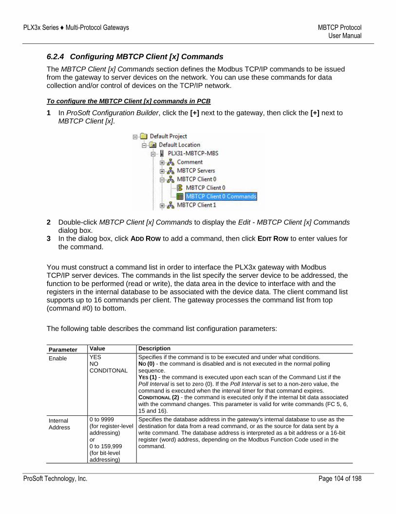
PLX3x Series ♦ Multi-Protocol Gateways MBTCP Protocol User Manual
ProSoft Technology, Inc. Page 104 of 198
6.2.4 Configuring MBTCP Client [x] Commands
The MBTCP Client [x] Commands section defines the Modbus TCP/IP commands to be issued from the gateway to server devices on the network. You can use these commands for data collection and/or control of devices on the TCP/IP network.
To configure the MBTCP Client [x] commands in PCB
1 In ProSoft Configuration Builder, click the [+] next to the gateway, then click the [+] next to MBTCP Client [x].
2 Double-click MBTCP Client [x] Commands to display the Edit - MBTCP Client [x] Commands dialog box.
3 In the dialog box, click ADD ROW to add a command, then click EDIT ROW to enter values for the command.
You must construct a command list in order to interface the PLX3x gateway with Modbus TCP/IP server devices. The commands in the list specify the server device to be addressed, the function to be performed (read or write), the data area in the device to interface with and the registers in the internal database to be associated with the device data. The client command list supports up to 16 commands per client. The gateway processes the command list from top (command #0) to bottom.
The following table describes the command list configuration parameters:
Parameter Value Description
Enable YES NO CONDITONAL
Specifies if the command is to be executed and under what conditions. NO (0) - the command is disabled and is not executed in the normal polling
sequence. YES (1) - the command is executed upon each scan of the Command List if the Poll Interval is set to zero (0). If the Poll Interval is set to a non-zero value, the command is executed when the interval timer for that command expires. CONDITIONAL (2) - the command is executed only if the internal bit data associated
with the command changes. This parameter is valid for write commands (FC 5, 6, 15 and 16).
Internal Address
0 to 9999 (for register-level addressing) or 0 to 159,999 (for bit-level addressing)
Specifies the database address in the gateway's internal database to use as the destination for data from a read command, or as the source for data sent by a write command. The database address is interpreted as a bit address or a 16-bit register (word) address, depending on the Modbus Function Code used in the command.
PLX3x Series ♦ Multi-Protocol Gateways MBTCP Protocol User Manual
ProSoft Technology, Inc. Page 105 of 198
Parameter Value Description
For Modbus functions 1, 2, 5, and 15, this parameter is interpreted as a bit-level address. The allowable range is 0 to 159,999. Note: This bit address range is available with ProSoft Configuration Builder
(PCB) v4.6 or later. Previous versions have a range of 0 to 65535. For Modbus functions 3, 4, 6, and 16, this parameter is interpreted as a
register-level address.
Poll Interval 0 to 65535 Specifies the minimum interval between executions of continuous commands. The value is in tenths of a second. If you enter a value of 100, the command executes no more frequently than once every 10 seconds.
Reg Count 1 to 125 (for registers) or 1 to 800 (for coils)
Specifies the number of 16-bit registers or binary bits to be transferred by the command.
Modbus functions 5 and 6 ignore this field as they apply only to a single data point.
For Modbus functions 1, 2, and 15, this parameter sets the number of bits (inputs or coils) transferred by the command.
For Modbus functions 3, 4, and 16, this parameter sets the number of registers transferred by the command.
Swap Code No Change Word Swap Word and Byte Swap Byte Swap
Specifies if and how the order of bytes in data received or sent is to be rearranged. Different manufacturers store and transmit multi-byte data in different combinations. You can use this parameter when dealing with floating-point or other multi-byte values, as there is no standard method of storing these data types. You can set this parameter to rearrange the byte order of data received or sent into an order more useful or convenient for other applications. NO CHANGE (0) - No change is made in the byte ordering (1234 = 1234). WORD SWAP (1) -The words are swapped (1234=3412). WORD AND BYTE SWAP (2) - The words are swapped, then the bytes in each word
are swapped (1234=4321). BYTE SWAP (3) - The bytes in each word are swapped (1234=2143).
These swap operations affect 4-byte (2-word) groups of data. Therefore, data swapping using Swap Codes should be done only when using an even number of words, such as 32-bit integer or floating-point data.
Node IP Address
xxx.xxx.xxx.xxx IP address of the device being addressed by the command.
Serv Port 502 or other supported port on server
Service Port on which communication will occur. Use a value of 502 when addressing Modbus TCP/IP servers that are compatible with the Schneider Electric MBAP specifications (this will be most devices). If the server device supports another Service Port, enter the Service Port value for this parameter.
Slave Address
1 to 255 (0 is a broadcast)
Specifies the node address of a remote Modbus Serial device through a Modbus Ethernet to Serial converter. Note: Most Modbus devices only accept addresses in the range of 1 to 247, so
check with the slave device manufacturer to see if the slave device can use addresses 248 to 255. If the value is set to zero, the command will be a broadcast message on the network. The Modbus protocol permits broadcast commands for write operations. Do not use node address 0 for read operations.
Modbus Function
1, 2, 3, 4, 5, 6, 15, or 16
Specifies the Modbus Function Code to be executed by the command. These function codes are defined in the Modbus protocol. More information on the protocol is available from www.modbus.org (http://www.modbus.org) or see About the Modbus Protocol (page 112). The following function codes are supported by the gateway. 1 - Read Coil Status 2 - Read Input Status 3 - Read Holding Registers 4 - Read Input Registers 5 - Force (Write) Single Coil 6 - Preset (Write) Single Register 15 - Force Multiple Coils
PLX3x Series ♦ Multi-Protocol Gateways MBTCP Protocol User Manual
ProSoft Technology, Inc. Page 106 of 198
Parameter Value Description
16 - Preset Multiple Registers
MB Address in Device
Varies Specifies the starting Modbus register or bit address in the server to be used by the command. Refer to the documentation of each Modbus server device for the register and bit address assignments valid for that device. The Modbus Function Code determines whether the address is a register-level or bit-level OFFSET address into a given data type range. The offset is the target data address in the server minus the base address for that data type. Base addresses for the different data types are:
00001 or 000001 (0x0001) for bit-level Coil data (Function Codes 1, 5, and 15).
10001 or 100001 (1x0001) for bit-level Input Status data (Function Code 2) 30001 or 300001 (3x0001) for Input Register data (Function Code 4) 40001 or 400001 (4x0001) for Holding Register data (Function Codes 3, 6,
and 16). Address calculation examples: For bit-level Coil commands (FC 1, 5, or 15) to read or write a Coil 0X
address 00001, specify a value of 0 (00001 - 00001 = 0). For Coil address 00115, specify 114
(00115 - 00001 = 114) For register read or write commands (FC 3, 6, or 16) 4X range, for 40001,
specify a value of 0 (40001 - 40001 = 0).
For 01101, 11101, 31101 or 41101, specify a value of 1100. (01101 - 00001 = 1100) (11101 -10001 = 1100) (31101 - 30001 = 1100) (41101 - 40001 = 1100)
Note: If the documentation for a particular Modbus server device lists data
addresses in hexadecimal (base16) notation, you must convert the hexadecimal value to a decimal value for this parameter. In such cases, it is not usually necessary to subtract 1 from the converted decimal number, as this addressing scheme typically uses the exact offset address expressed as a hexadecimal number.
Comment Optional 32 character comment for the command.
PLX3x Series ♦ Multi-Protocol Gateways MBTCP Protocol User Manual
ProSoft Technology, Inc. Page 107 of 198
6.3 Network Diagnostics
6.3.1 MBTCP PCB Diagnostics
The best way to troubleshoot the MBTCP driver is to use ProSoft Configuration Builder to access the diagnostic capabilities of the gateway through the Ethernet debug port. For instructions on how to access the diagnostics, see Diagnostics and Troubleshooting (page 32).
The following table summarizes the status information available in PCB for the MBTCP driver:
Connection Type Submenu Item Description
MBTCP Server Config Configuration settings for Server Connections.
Comm Status Status of the Server Connections. Displays a summary of the requests, responses, and errors.
MBTCP Client [x] Config Configuration settings for Client [x] Connections.
Comm Status Status information for Client [x] commands. Displays a summary of all the errors resulting from Client [x] commands.
Modbus Commands
Configuration for the Client [x] Modbus command list.
Modbus Cmd Errors (Decimal)
Current error codes for each command on the Client [x] command list in decimal number format. A zero means there is currently no error for the command.
Modbus Cmd Errors (Hex)
Current error codes for each command on the Client [x] command list in hexadecimal number format. A zero means there is currently no error for the command.
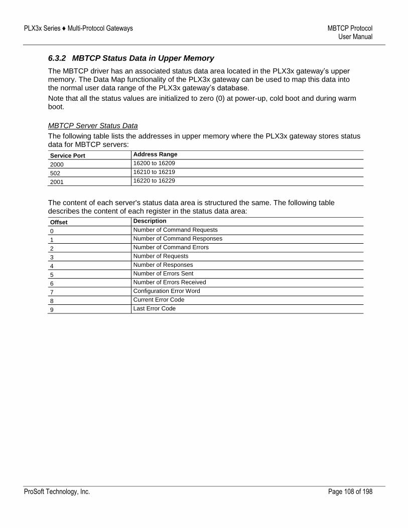
PLX3x Series ♦ Multi-Protocol Gateways MBTCP Protocol User Manual
ProSoft Technology, Inc. Page 108 of 198
6.3.2 MBTCP Status Data in Upper Memory
The MBTCP driver has an associated status data area located in the PLX3x gateway’s upper memory. The Data Map functionality of the PLX3x gateway can be used to map this data into the normal user data range of the PLX3x gateway’s database.
Note that all the status values are initialized to zero (0) at power-up, cold boot and during warm boot.
MBTCP Server Status Data
The following table lists the addresses in upper memory where the PLX3x gateway stores status data for MBTCP servers:
Service Port Address Range
2000 16200 to 16209
502 16210 to 16219
2001 16220 to 16229
The content of each server's status data area is structured the same. The following table describes the content of each register in the status data area:
Offset Description
0 Number of Command Requests
1 Number of Command Responses
2 Number of Command Errors
3 Number of Requests
4 Number of Responses
5 Number of Errors Sent
6 Number of Errors Received
7 Configuration Error Word
8 Current Error Code
9 Last Error Code
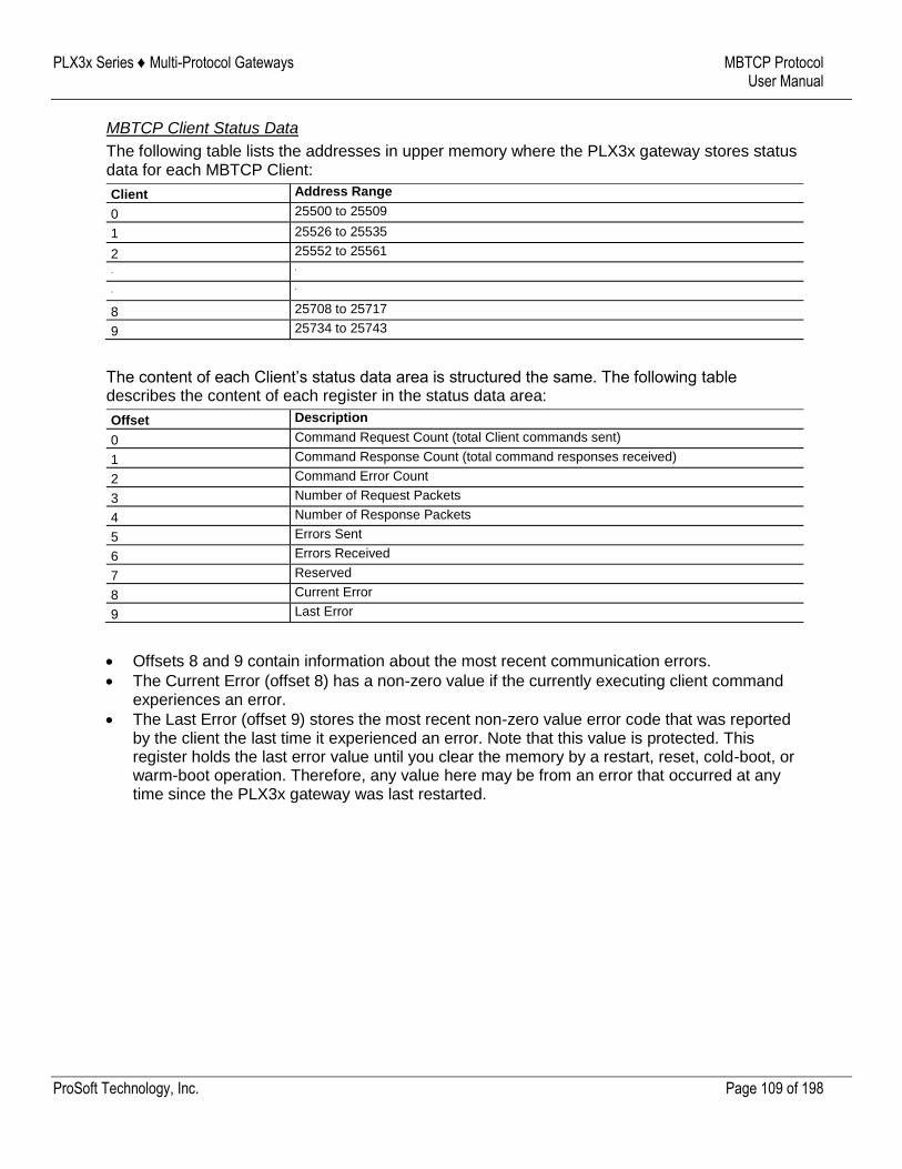
PLX3x Series ♦ Multi-Protocol Gateways MBTCP Protocol User Manual
ProSoft Technology, Inc. Page 109 of 198
MBTCP Client Status Data
The following table lists the addresses in upper memory where the PLX3x gateway stores status data for each MBTCP Client:
Client Address Range
0 25500 to 25509
1 25526 to 25535
2 25552 to 25561
. .
. .
8 25708 to 25717
9 25734 to 25743
The content of each Client’s status data area is structured the same. The following table describes the content of each register in the status data area:
Offset Description
0 Command Request Count (total Client commands sent)
1 Command Response Count (total command responses received)
2 Command Error Count
3 Number of Request Packets
4 Number of Response Packets
5 Errors Sent
6 Errors Received
7 Reserved
8 Current Error
9 Last Error
Offsets 8 and 9 contain information about the most recent communication errors.
The Current Error (offset 8) has a non-zero value if the currently executing client command experiences an error.
The Last Error (offset 9) stores the most recent non-zero value error code that was reported by the client the last time it experienced an error. Note that this value is protected. This register holds the last error value until you clear the memory by a restart, reset, cold-boot, or warm-boot operation. Therefore, any value here may be from an error that occurred at any time since the PLX3x gateway was last restarted.
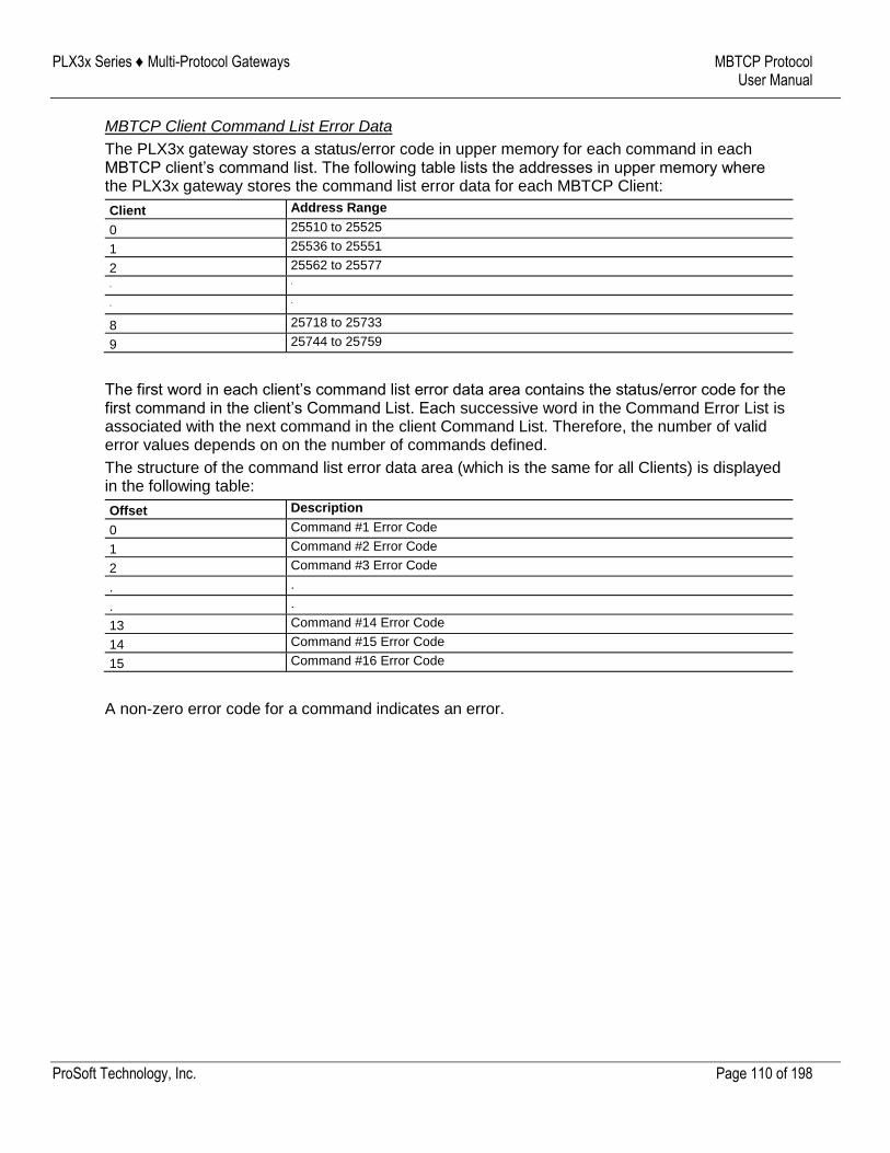
PLX3x Series ♦ Multi-Protocol Gateways MBTCP Protocol User Manual
ProSoft Technology, Inc. Page 110 of 198
MBTCP Client Command List Error Data
The PLX3x gateway stores a status/error code in upper memory for each command in each MBTCP client’s command list. The following table lists the addresses in upper memory where the PLX3x gateway stores the command list error data for each MBTCP Client:
Client Address Range
0 25510 to 25525
1 25536 to 25551
2 25562 to 25577
. .
. .
8 25718 to 25733
9 25744 to 25759
The first word in each client’s command list error data area contains the status/error code for the first command in the client’s Command List. Each successive word in the Command Error List is associated with the next command in the client Command List. Therefore, the number of valid error values depends on on the number of commands defined.
The structure of the command list error data area (which is the same for all Clients) is displayed in the following table:
Offset Description
0 Command #1 Error Code
1 Command #2 Error Code
2 Command #3 Error Code
. .
. .
13 Command #14 Error Code
14 Command #15 Error Code
15 Command #16 Error Code
A non-zero error code for a command indicates an error.
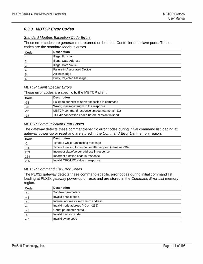
PLX3x Series ♦ Multi-Protocol Gateways MBTCP Protocol User Manual
ProSoft Technology, Inc. Page 111 of 198
6.3.3 MBTCP Error Codes
Standard Modbus Exception Code Errors
These error codes are generated or returned on both the Controller and slave ports. These codes are the standard Modbus errors.
Code Description
1 Illegal Function
2 Illegal Data Address
3 Illegal Data Value
4 Failure in Associated Device
5 Acknowledge
6 Busy, Rejected Message
MBTCP Client Specific Errors
These error codes are specific to the MBTCP client.
Code Description
-33 Failed to connect to server specified in command
-35 Wrong message length in the response
-36 MBTCP command response timeout (same as -11)
-37 TCP/IP connection ended before session finished
MBTCP Communication Error Codes
The gateway detects these command-specific error codes during initial command list loading at gateway power-up or reset and are stored in the Command Error List memory region.
Code Description
-2 Timeout while transmitting message
-11 Timeout waiting for response after request (same as -36)
253 Incorrect slave/server address in response
254 Incorrect function code in response
255 Invalid CRC/LRC value in response
MBTCP Command List Error Codes
The PLX3x gateway detects these command-specific error codes during initial command list loading at PLX3x gateway power-up or reset and are stored in the Command Error List memory region.
Code Description
-40 Too few parameters
-41 Invalid enable code
-42 Internal address > maximum address
-43 Invalid node address (<0 or >255)
-44 Count parameter set to 0
-45 Invalid function code
-46 Invalid swap code
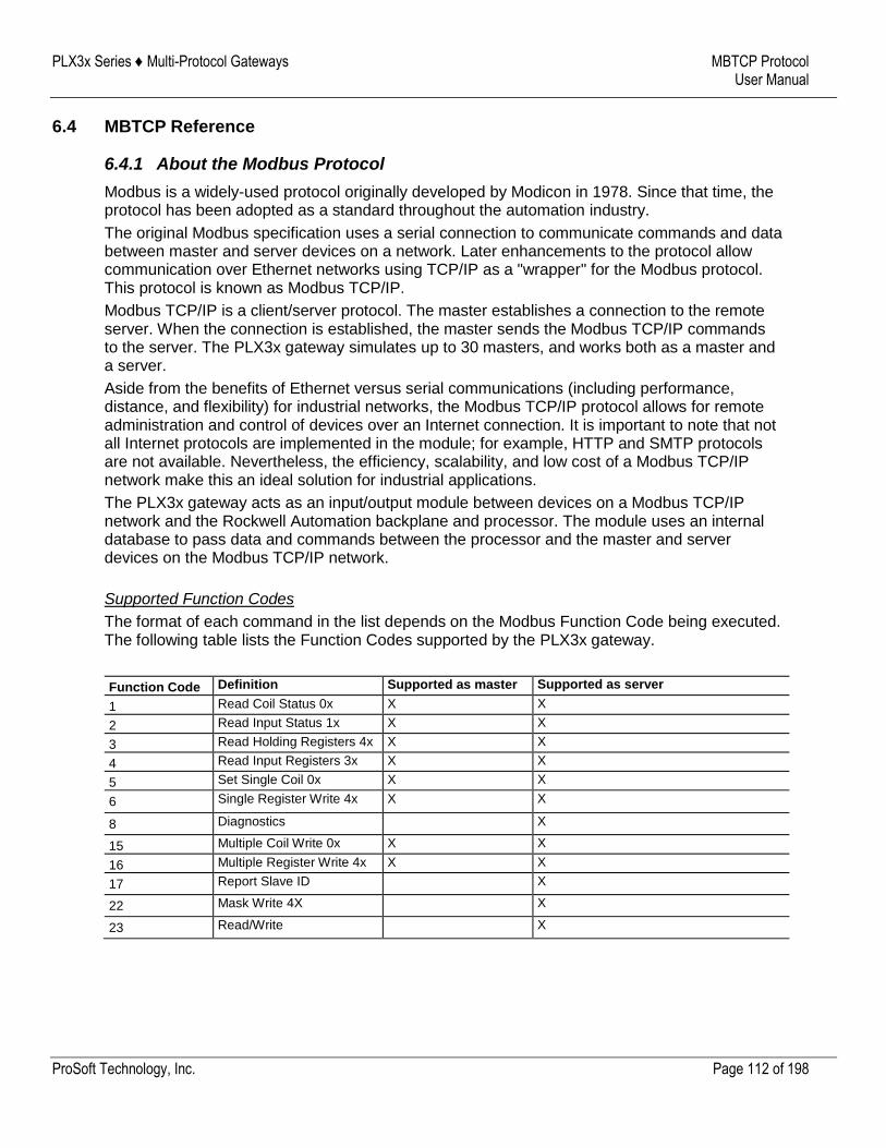
PLX3x Series ♦ Multi-Protocol Gateways MBTCP Protocol User Manual
ProSoft Technology, Inc. Page 112 of 198
6.4 MBTCP Reference
6.4.1 About the Modbus Protocol
Modbus is a widely-used protocol originally developed by Modicon in 1978. Since that time, the protocol has been adopted as a standard throughout the automation industry.
The original Modbus specification uses a serial connection to communicate commands and data between master and server devices on a network. Later enhancements to the protocol allow communication over Ethernet networks using TCP/IP as a "wrapper" for the Modbus protocol. This protocol is known as Modbus TCP/IP.
Modbus TCP/IP is a client/server protocol. The master establishes a connection to the remote server. When the connection is established, the master sends the Modbus TCP/IP commands to the server. The PLX3x gateway simulates up to 30 masters, and works both as a master and a server.
Aside from the benefits of Ethernet versus serial communications (including performance, distance, and flexibility) for industrial networks, the Modbus TCP/IP protocol allows for remote administration and control of devices over an Internet connection. It is important to note that not all Internet protocols are implemented in the module; for example, HTTP and SMTP protocols are not available. Nevertheless, the efficiency, scalability, and low cost of a Modbus TCP/IP network make this an ideal solution for industrial applications.
The PLX3x gateway acts as an input/output module between devices on a Modbus TCP/IP network and the Rockwell Automation backplane and processor. The module uses an internal database to pass data and commands between the processor and the master and server devices on the Modbus TCP/IP network.
Supported Function Codes
The format of each command in the list depends on the Modbus Function Code being executed. The following table lists the Function Codes supported by the PLX3x gateway.
Function Code Definition Supported as master Supported as server
1 Read Coil Status 0x X X
2 Read Input Status 1x X X
3 Read Holding Registers 4x X X
4 Read Input Registers 3x X X
5 Set Single Coil 0x X X
6 Single Register Write 4x X X
8 Diagnostics X
15 Multiple Coil Write 0x X X
16 Multiple Register Write 4x X X
17 Report Slave ID X
22 Mask Write 4X X
23 Read/Write X
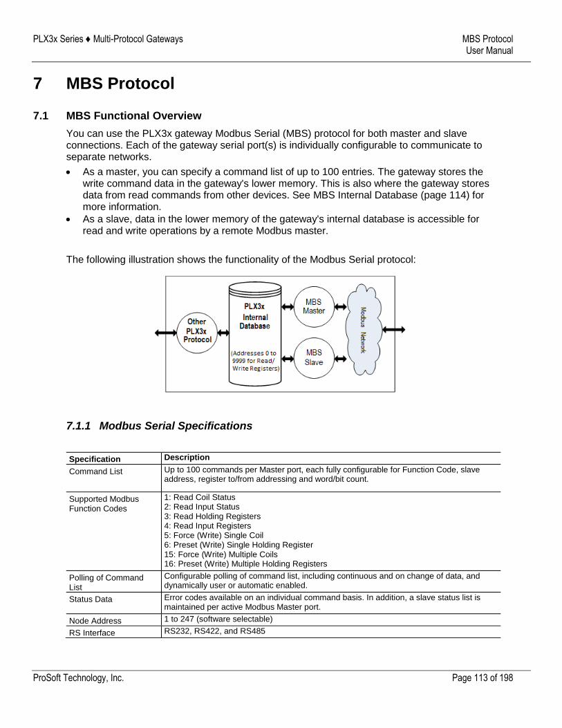
PLX3x Series ♦ Multi-Protocol Gateways MBS Protocol User Manual
ProSoft Technology, Inc. Page 113 of 198
7 MBS Protocol
7.1 MBS Functional Overview
You can use the PLX3x gateway Modbus Serial (MBS) protocol for both master and slave connections. Each of the gateway serial port(s) is individually configurable to communicate to separate networks.
As a master, you can specify a command list of up to 100 entries. The gateway stores the write command data in the gateway's lower memory. This is also where the gateway stores data from read commands from other devices. See MBS Internal Database (page 114) for more information.
As a slave, data in the lower memory of the gateway's internal database is accessible for read and write operations by a remote Modbus master.
The following illustration shows the functionality of the Modbus Serial protocol:
7.1.1 Modbus Serial Specifications
Specification Description
Command List Up to 100 commands per Master port, each fully configurable for Function Code, slave address, register to/from addressing and word/bit count.
Supported Modbus Function Codes
1: Read Coil Status 2: Read Input Status 3: Read Holding Registers 4: Read Input Registers 5: Force (Write) Single Coil 6: Preset (Write) Single Holding Register 15: Force (Write) Multiple Coils 16: Preset (Write) Multiple Holding Registers
Polling of Command List
Configurable polling of command list, including continuous and on change of data, and dynamically user or automatic enabled.
Status Data Error codes available on an individual command basis. In addition, a slave status list is maintained per active Modbus Master port.
Node Address 1 to 247 (software selectable)
RS Interface RS232, RS422, and RS485
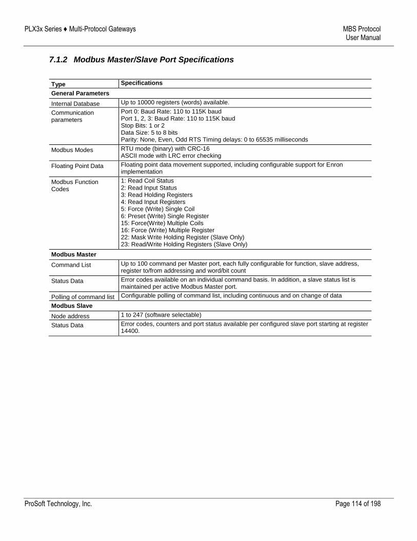
PLX3x Series ♦ Multi-Protocol Gateways MBS Protocol User Manual
ProSoft Technology, Inc. Page 114 of 198
7.1.2 Modbus Master/Slave Port Specifications
Type Specifications
General Parameters
Internal Database Up to 10000 registers (words) available.
Communication parameters
Port 0: Baud Rate: 110 to 115K baud Port 1, 2, 3: Baud Rate: 110 to 115K baud Stop Bits: 1 or 2 Data Size: 5 to 8 bits Parity: None, Even, Odd RTS Timing delays: 0 to 65535 milliseconds
Modbus Modes RTU mode (binary) with CRC-16 ASCII mode with LRC error checking
Floating Point Data Floating point data movement supported, including configurable support for Enron implementation
Modbus Function Codes
1: Read Coil Status 2: Read Input Status 3: Read Holding Registers 4: Read Input Registers 5: Force (Write) Single Coil 6: Preset (Write) Single Register 15: Force(Write) Multiple Coils 16: Force (Write) Multiple Register 22: Mask Write Holding Register (Slave Only) 23: Read/Write Holding Registers (Slave Only)
Modbus Master
Command List Up to 100 command per Master port, each fully configurable for function, slave address, register to/from addressing and word/bit count
Status Data Error codes available on an individual command basis. In addition, a slave status list is maintained per active Modbus Master port.
Polling of command list Configurable polling of command list, including continuous and on change of data
Modbus Slave
Node address 1 to 247 (software selectable)
Status Data Error codes, counters and port status available per configured slave port starting at register 14400.
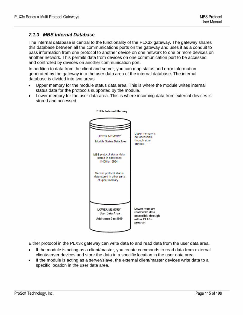
PLX3x Series ♦ Multi-Protocol Gateways MBS Protocol User Manual
ProSoft Technology, Inc. Page 115 of 198
7.1.3 MBS Internal Database
The internal database is central to the functionality of the PLX3x gateway. The gateway shares this database between all the communications ports on the gateway and uses it as a conduit to pass information from one protocol to another device on one network to one or more devices on another network. This permits data from devices on one communication port to be accessed and controlled by devices on another communication port.
In addition to data from the client and server, you can map status and error information generated by the gateway into the user data area of the internal database. The internal database is divided into two areas:
Upper memory for the module status data area. This is where the module writes internal status data for the protocols supported by the module.
Lower memory for the user data area. This is where incoming data from external devices is stored and accessed.
Either protocol in the PLX3x gateway can write data to and read data from the user data area.
If the module is acting as a client/master, you create commands to read data from external client/server devices and store the data in a specific location in the user data area.
If the module is acting as a server/slave, the external client/master devices write data to a specific location in the user data area.
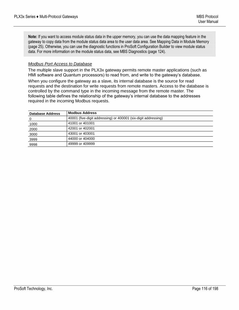
PLX3x Series ♦ Multi-Protocol Gateways MBS Protocol User Manual
ProSoft Technology, Inc. Page 116 of 198
Note: If you want to access module status data in the upper memory, you can use the data mapping feature in the gateway to copy data from the module status data area to the user data area. See Mapping Data in Module Memory (page 25). Otherwise, you can use the diagnostic functions in ProSoft Configuration Builder to view module status data. For more information on the module status data, see MBS Diagnostics (page 124).
Modbus Port Access to Database
The multiple slave support in the PLX3x gateway permits remote master applications (such as HMI software and Quantum processors) to read from, and write to the gateway’s database.
When you configure the gateway as a slave, its internal database is the source for read requests and the destination for write requests from remote masters. Access to the database is controlled by the command type in the incoming message from the remote master. The following table defines the relationship of the gateway’s internal database to the addresses required in the incoming Modbus requests.
Database Address Modbus Address
0 40001 (five-digit addressing) or 400001 (six-digit addressing)
1000 41001 or 401001
2000 42001 or 402001
3000 43001 or 403001
3999 44000 or 404000
9998 49999 or 409999
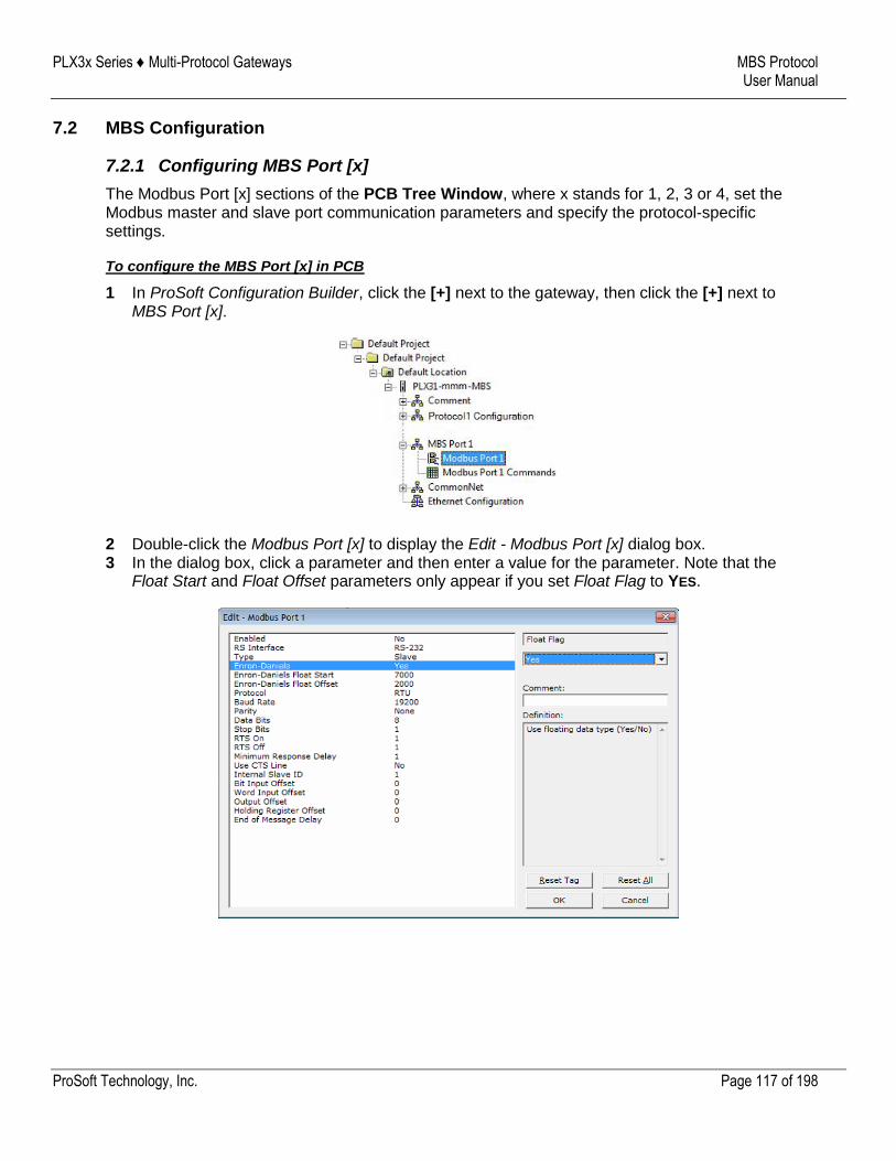
PLX3x Series ♦ Multi-Protocol Gateways MBS Protocol User Manual
ProSoft Technology, Inc. Page 117 of 198
7.2 MBS Configuration
7.2.1 Configuring MBS Port [x]
The Modbus Port [x] sections of the PCB Tree Window, where x stands for 1, 2, 3 or 4, set the Modbus master and slave port communication parameters and specify the protocol-specific settings.
To configure the MBS Port [x] in PCB
1 In ProSoft Configuration Builder, click the [+] next to the gateway, then click the [+] next to MBS Port [x].
2 Double-click the Modbus Port [x] to display the Edit - Modbus Port [x] dialog box. 3 In the dialog box, click a parameter and then enter a value for the parameter. Note that the
Float Start and Float Offset parameters only appear if you set Float Flag to YES.
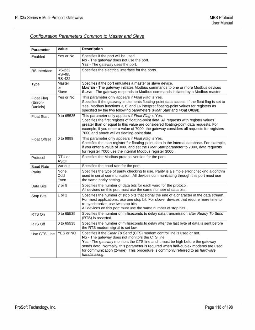
PLX3x Series ♦ Multi-Protocol Gateways MBS Protocol User Manual
ProSoft Technology, Inc. Page 118 of 198
Configuration Parameters Common to Master and Slave
Parameter Value Description
Enabled Yes or No Specifies if the port will be used. NO - The gateway does not use the port. YES - The gateway uses the port.
RS Interface RS-232 RS-485 RS-422
Specifies the electrical interface for the ports.
Type Master or Slave
Specifies if the port emulates a master or slave device. MASTER - The gateway initiates Modbus commands to one or more Modbus devices SLAVE - The gateway responds to Modbus commands initiated by a Modbus master
Float Flag (Enron-Daniels)
Yes or No This parameter only appears if Float Flag is Yes.
Specifies if the gateway implements floating-point data access. If the float flag is set to Yes, Modbus functions 3, 6, and 16 interpret floating-point values for registers as specified by the two following parameters (Float Start and Float Offset).
Float Start 0 to 65535 This parameter only appears if Float Flag is Yes.
Specifies the first register of floating-point data. All requests with register values greater than or equal to this value are considered floating-point data requests. For example, if you enter a value of 7000, the gateway considers all requests for registers 7000 and above will as floating-point data.
Float Offset 0 to 9998 This parameter only appears if Float Flag is Yes.
Specifies the start register for floating-point data in the internal database. For example, if you enter a value of 3000 and set the Float Start parameter to 7000, data requests for register 7000 use the internal Modbus register 3000.
Protocol RTU or ASCII
Specifies the Modbus protocol version for the port.
Baud Rate Various Specifies the baud rate for the port.
Parity None Odd Even
Specifies the type of parity checking to use. Parity is a simple error checking algorithm used in serial communication. All devices communicating through this port must use the same parity setting.
Data Bits 7 or 8 Specifies the number of data bits for each word for the protocol. All devices on this port must use the same number of data bits.
Stop Bits 1 or 2 Specifies the number of stop bits that signal the end of a character in the data stream. For most applications, use one stop bit. For slower devices that require more time to re-synchronize, use two stop bits. All devices on this port must use the same number of stop bits.
RTS On 0 to 65535 Specifies the number of milliseconds to delay data transmission after Ready To Send (RTS) is asserted.
RTS Off 0 to 65535 Specifies the number of milliseconds to delay after the last byte of data is sent before the RTS modem signal is set low.
Use CTS Line YES or NO Specifies if the Clear To Send (CTS) modem control line is used or not. NO - The gateway does not monitors the CTS line. YES - The gateway monitors the CTS line and it must be high before the gateway
sends data. Normally, this parameter is required when half-duplex modems are used for communication (2-wire). This procedure is commonly referred to as hardware handshaking.
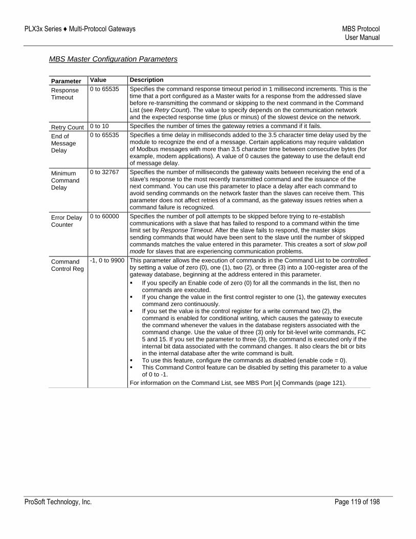
PLX3x Series ♦ Multi-Protocol Gateways MBS Protocol User Manual
ProSoft Technology, Inc. Page 119 of 198
MBS Master Configuration Parameters
Parameter Value Description
Response Timeout
0 to 65535 Specifies the command response timeout period in 1 millisecond increments. This is the time that a port configured as a Master waits for a response from the addressed slave before re-transmitting the command or skipping to the next command in the Command List (see Retry Count). The value to specify depends on the communication network and the expected response time (plus or minus) of the slowest device on the network.
Retry Count 0 to 10 Specifies the number of times the gateway retries a command if it fails.
End of Message Delay
0 to 65535 Specifies a time delay in milliseconds added to the 3.5 character time delay used by the module to recognize the end of a message. Certain applications may require validation of Modbus messages with more than 3.5 character time between consecutive bytes (for example, modem applications). A value of 0 causes the gateway to use the default end of message delay.
Minimum Command Delay
0 to 32767 Specifies the number of milliseconds the gateway waits between receiving the end of a slave's response to the most recently transmitted command and the issuance of the next command. You can use this parameter to place a delay after each command to avoid sending commands on the network faster than the slaves can receive them. This parameter does not affect retries of a command, as the gateway issues retries when a command failure is recognized.
Error Delay Counter
0 to 60000 Specifies the number of poll attempts to be skipped before trying to re-establish communications with a slave that has failed to respond to a command within the time limit set by Response Timeout. After the slave fails to respond, the master skips sending commands that would have been sent to the slave until the number of skipped commands matches the value entered in this parameter. This creates a sort of slow poll mode for slaves that are experiencing communication problems.
Command Control Reg
-1, 0 to 9900 This parameter allows the execution of commands in the Command List to be controlled by setting a value of zero (0), one (1), two (2), or three (3) into a 100-register area of the gateway database, beginning at the address entered in this parameter.
If you specify an Enable code of zero (0) for all the commands in the list, then no commands are executed.
If you change the value in the first control register to one (1), the gateway executes command zero continuously.
If you set the value is the control register for a write command two (2), the command is enabled for conditional writing, which causes the gateway to execute the command whenever the values in the database registers associated with the command change. Use the value of three (3) only for bit-level write commands, FC 5 and 15. If you set the parameter to three (3), the command is executed only if the internal bit data associated with the command changes. It also clears the bit or bits in the internal database after the write command is built.
To use this feature, configure the commands as disabled (enable code = 0). This Command Control feature can be disabled by setting this parameter to a value
of 0 to -1.
For information on the Command List, see MBS Port [x] Commands (page 121).
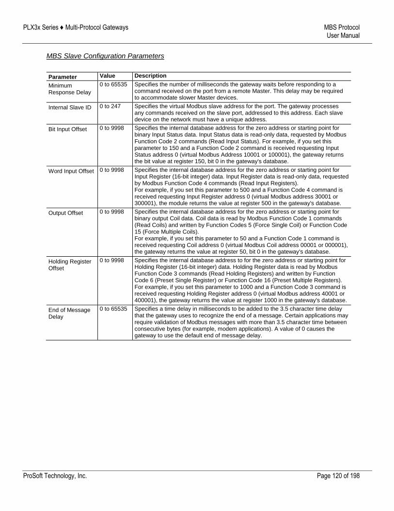
PLX3x Series ♦ Multi-Protocol Gateways MBS Protocol User Manual
ProSoft Technology, Inc. Page 120 of 198
MBS Slave Configuration Parameters
Parameter Value Description
Minimum Response Delay
0 to 65535 Specifies the number of milliseconds the gateway waits before responding to a command received on the port from a remote Master. This delay may be required to accommodate slower Master devices.
Internal Slave ID 0 to 247 Specifies the virtual Modbus slave address for the port. The gateway processes any commands received on the slave port, addressed to this address. Each slave device on the network must have a unique address.
Bit Input Offset 0 to 9998 Specifies the internal database address for the zero address or starting point for binary Input Status data. Input Status data is read-only data, requested by Modbus Function Code 2 commands (Read Input Status). For example, if you set this parameter to 150 and a Function Code 2 command is received requesting Input Status address 0 (virtual Modbus Address 10001 or 100001), the gateway returns the bit value at register 150, bit 0 in the gateway's database.
Word Input Offset 0 to 9998 Specifies the internal database address for the zero address or starting point for Input Register (16-bit integer) data. Input Register data is read-only data, requested by Modbus Function Code 4 commands (Read Input Registers). For example, if you set this parameter to 500 and a Function Code 4 command is received requesting Input Register address 0 (virtual Modbus address 30001 or 300001), the module returns the value at register 500 in the gateway's database.
Output Offset 0 to 9998 Specifies the internal database address for the zero address or starting point for binary output Coil data. Coil data is read by Modbus Function Code 1 commands (Read Coils) and written by Function Codes 5 (Force Single Coil) or Function Code 15 (Force Multiple Coils). For example, if you set this parameter to 50 and a Function Code 1 command is received requesting Coil address 0 (virtual Modbus Coil address 00001 or 000001), the gateway returns the value at register 50, bit 0 in the gateway's database.
Holding Register Offset
0 to 9998 Specifies the internal database address to for the zero address or starting point for Holding Register (16-bit integer) data. Holding Register data is read by Modbus Function Code 3 commands (Read Holding Registers) and written by Function Code 6 (Preset Single Register) or Function Code 16 (Preset Multiple Registers). For example, if you set this parameter to 1000 and a Function Code 3 command is received requesting Holding Register address 0 (virtual Modbus address 40001 or 400001), the gateway returns the value at register 1000 in the gateway's database.
End of Message Delay
0 to 65535 Specifies a time delay in milliseconds to be added to the 3.5 character time delay that the gateway uses to recognize the end of a message. Certain applications may require validation of Modbus messages with more than 3.5 character time between consecutive bytes (for example, modem applications). A value of 0 causes the gateway to use the default end of message delay.
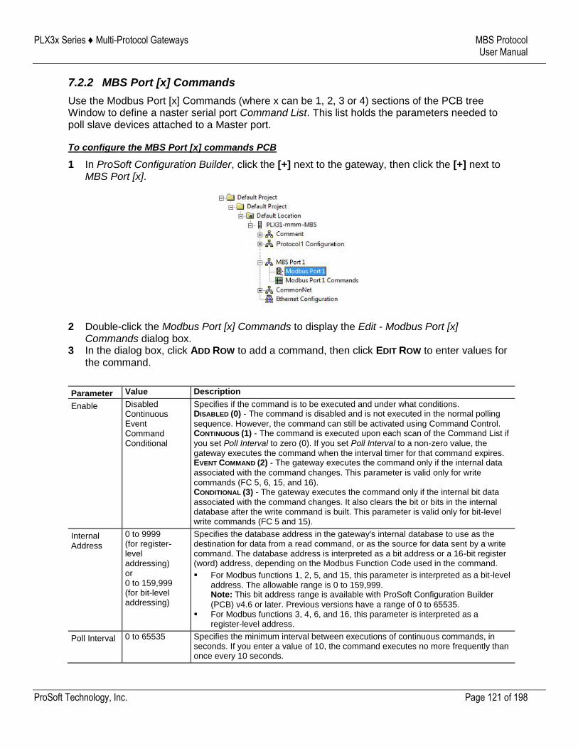
PLX3x Series ♦ Multi-Protocol Gateways MBS Protocol User Manual
ProSoft Technology, Inc. Page 121 of 198
7.2.2 MBS Port [x] Commands
Use the Modbus Port [x] Commands (where x can be 1, 2, 3 or 4) sections of the PCB tree Window to define a naster serial port Command List. This list holds the parameters needed to poll slave devices attached to a Master port.
To configure the MBS Port [x] commands PCB
1 In ProSoft Configuration Builder, click the [+] next to the gateway, then click the [+] next to MBS Port [x].
2 Double-click the Modbus Port [x] Commands to display the Edit - Modbus Port [x] Commands dialog box.
3 In the dialog box, click ADD ROW to add a command, then click EDIT ROW to enter values for the command.
Parameter Value Description
Enable Disabled Continuous Event Command Conditional
Specifies if the command is to be executed and under what conditions. DISABLED (0) - The command is disabled and is not executed in the normal polling
sequence. However, the command can still be activated using Command Control. CONTINUOUS (1) - The command is executed upon each scan of the Command List if
you set Poll Interval to zero (0). If you set Poll Interval to a non-zero value, the gateway executes the command when the interval timer for that command expires. EVENT COMMAND (2) - The gateway executes the command only if the internal data
associated with the command changes. This parameter is valid only for write commands (FC 5, 6, 15, and 16). CONDITIONAL (3) - The gateway executes the command only if the internal bit data
associated with the command changes. It also clears the bit or bits in the internal database after the write command is built. This parameter is valid only for bit-level write commands (FC 5 and 15).
Internal Address
0 to 9999 (for register-level addressing) or 0 to 159,999 (for bit-level addressing)
Specifies the database address in the gateway's internal database to use as the destination for data from a read command, or as the source for data sent by a write command. The database address is interpreted as a bit address or a 16-bit register (word) address, depending on the Modbus Function Code used in the command.
For Modbus functions 1, 2, 5, and 15, this parameter is interpreted as a bit-level address. The allowable range is 0 to 159,999. Note: This bit address range is available with ProSoft Configuration Builder
(PCB) v4.6 or later. Previous versions have a range of 0 to 65535. For Modbus functions 3, 4, 6, and 16, this parameter is interpreted as a
register-level address.
Poll Interval 0 to 65535 Specifies the minimum interval between executions of continuous commands, in seconds. If you enter a value of 10, the command executes no more frequently than once every 10 seconds.
PLX3x Series ♦ Multi-Protocol Gateways MBS Protocol User Manual
ProSoft Technology, Inc. Page 122 of 198
Parameter Value Description
Reg Count 1 to 125 (for registers) or 1 to 800 (for coils)
Specifies the number of 16-bit registers or binary bits to be transferred by the command.
Modbus functions 5 and 6 ignore this field as they apply only to a single data point.
For Modbus functions 1, 2, and 15, this parameter sets the number of bits (inputs or coils) to be transferred by the command.
For Modbus functions 3, 4, and 16, this parameter sets the number of registers to be transferred by the command.
Swap Code No Change Word Swap Word and Byte Swap Byte Swap
Specifies if and how the order of bytes in data received or sent is rearranged. This option allows for the fact that different manufacturers store and transmit multi-byte data in different combinations. This parameter is helpful when dealing with floating-point or other multi-byte values, as there is no one standard method of storing these data types. You can set Swap Code to rearrange the byte order of data received or sent into an order more useful or convenient for other applications. NO CHANGE (0) - No change is made in the byte ordering (1234 = 1234) WORD SWAP (1) -The words are swapped (1234=3412) WORD AND BYTE SWAP (2) - The words are swapped, then the bytes in each word are
swapped (1234=4321) BYTE SWAP (3) - The bytes in each word are swapped (1234=2143)
These swap operations affect 4-byte (or 2-word) groups of data. Therefore, you should use data swapping only when using an even number of words, such as when 32-bit integer or floating-point data.
Node Address
1 to 255 (0 is a broadcast)
Specifies the node address of the Modbus slave device. Note: Most Modbus devices only accept addresses in the range of 1 to 247, so
check with the slave device manufacturer to see if a particular slave can use addresses 248 to 255. If you set the value to zero (0), the gateway broadcasts the command on the network. The Modbus protocol permits broadcast commands for write operations. Do not use node address 0 for read operations.
Modbus Function
1, 2, 3, 4, 5, 6, 15, or 16
Specifies the Modbus Function Code executed by the command. These function codes are defined in the Modbus protocol. More information on the protocol is available from www.modbus.org (http://www.modbus.org) or see About the Modbus Protocol (page 112).) The following function codes are supported by the gateway. 1 - Read Coil Status 2 - Read Input Status 3 - Read Holding Registers 4 - Read Input Registers 5 - Force (Write) Single Coil 6 - Preset (Write) Single Register 15 - Force Multiple Coils 16 - Preset Multiple Registers
PLX3x Series ♦ Multi-Protocol Gateways MBS Protocol User Manual
ProSoft Technology, Inc. Page 123 of 198
Parameter Value Description
MB Address in Device
Varies Specifies the starting Modbus register or bit address in the server for the command. Refer to the documentation of each Modbus server device for the register and bit address assignments valid for that device. The Modbus Function code determines whether the address is a register-level or bit-level OFFSET address into a given data type range. The offset is the target data address in the server minus the base address for that data type. Base addresses for the different data types are:
00001 or 000001 (0x0001) for bit-level Coil data (Function Codes 1, 5, and 15). 10001 or 100001 (1x0001) for bit-level Input Status data (Function Code 2) 30001 or 300001 (3x0001) for Input Register data (Function Code 4) 40001 or 400001 (4x0001) for Holding Register data (Function Codes 3, 6, and
16).
Address calculation examples:
For bit-level Coil commands (FC 1, 5, or 15) to read or write a Coil 0X address 00001, specify a value of 0 (00001 - 00001 = 0).
For Coil address 00115, specify 114 (00115 - 00001 = 114) For register read or write commands (FC 3, 6, or 16) 4X range, for 40001,
specify a value of 0 (40001 - 40001 = 0).
For 01101, 11101, 31101 or 41101, specify a value of 1100. (01101 - 00001 = 1100) (11101 -10001 = 1100) (31101 - 30001 = 1100) (41101 - 40001 = 1100)
Note: If the documentation for a particular Modbus server device lists data
addresses in hexadecimal (base16) notation, you must convert the hexadecimal value to a decimal value for this parameter. In such cases, you usually do not have to subtract 1 from the converted decimal number, as this addressing scheme typically uses the exact offset address expressed as a hexadecimal number.
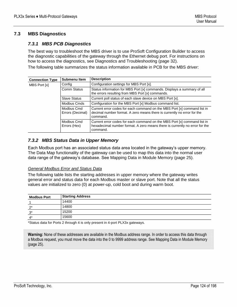
PLX3x Series ♦ Multi-Protocol Gateways MBS Protocol User Manual
ProSoft Technology, Inc. Page 124 of 198
7.3 MBS Diagnostics
7.3.1 MBS PCB Diagnostics
The best way to troubleshoot the MBS driver is to use ProSoft Configuration Builder to access the diagnostic capabilities of the gateway through the Ethernet debug port. For instructions on how to access the diagnostics, see Diagnostics and Troubleshooting (page 32).
The following table summarizes the status information available in PCB for the MBS driver:
Connection Type Submenu Item Description
MBS Port [x] Config Configuration settings for MBS Port [x].
Comm Status Status information for MBS Port [x] commands. Displays a summary of all the errors resulting from MBS Port [x] commands.
Slave Status Current poll status of each slave device on MBS Port [x].
Modbus Cmds Configuration for the MBS Port [x] Modbus command list.
Modbus Cmd Errors (Decimal)
Current error codes for each command on the MBS Port [x] command list in decimal number format. A zero means there is currently no error for the command.
Modbus Cmd Errors (Hex)
Current error codes for each command on the MBS Port [x] command list in hexadecimal number format. A zero means there is currently no error for the command.
7.3.2 MBS Status Data in Upper Memory
Each Modbus port has an associated status data area located in the gateway’s upper memory. The Data Map functionality of the gateway can be used to map this data into the normal user data range of the gateway’s database. See Mapping Data in Module Memory (page 25).
General Modbus Error and Status Data
The following table lists the starting addresses in upper memory where the gateway writes general error and status data for each Modbus master or slave port. Note that all the status values are initialized to zero (0) at power-up, cold boot and during warm boot.
Modbus Port Starting Address
1 14400
2* 14800
3* 15200
4* 15600
*Status data for Ports 2 through 4 is only present in 4-port PLX3x gateways.
Warning: None of these addresses are available in the Modbus address range. In order to access this data through a Modbus request, you must move the data into the 0 to 9999 address range. See Mapping Data in Module Memory (page 25).
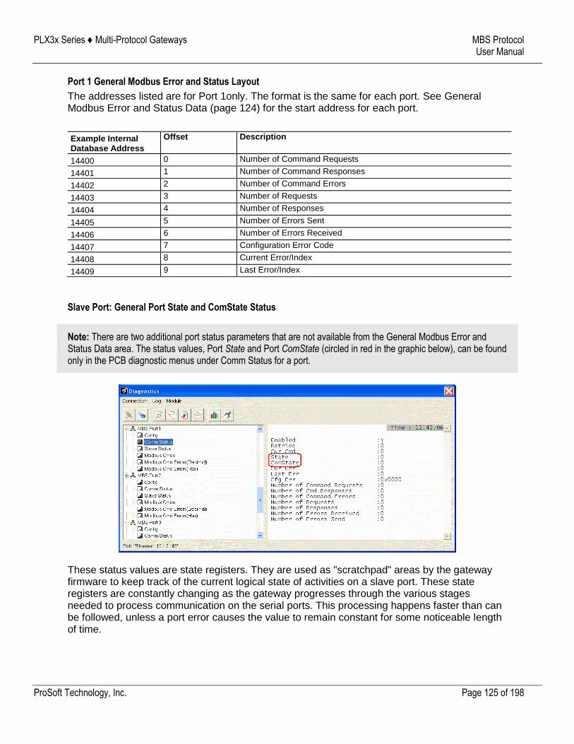
PLX3x Series ♦ Multi-Protocol Gateways MBS Protocol User Manual
ProSoft Technology, Inc. Page 125 of 198
Port 1 General Modbus Error and Status Layout
The addresses listed are for Port 1only. The format is the same for each port. See General Modbus Error and Status Data (page 124) for the start address for each port.
Example Internal Database Address
Offset Description
14400 0 Number of Command Requests
14401 1 Number of Command Responses
14402 2 Number of Command Errors
14403 3 Number of Requests
14404 4 Number of Responses
14405 5 Number of Errors Sent
14406 6 Number of Errors Received
14407 7 Configuration Error Code
14408 8 Current Error/Index
14409 9 Last Error/Index
Slave Port: General Port State and ComState Status
Note: There are two additional port status parameters that are not available from the General Modbus Error and Status Data area. The status values, Port State and Port ComState (circled in red in the graphic below), can be found only in the PCB diagnostic menus under Comm Status for a port.
These status values are state registers. They are used as "scratchpad" areas by the gateway firmware to keep track of the current logical state of activities on a slave port. These state registers are constantly changing as the gateway progresses through the various stages needed to process communication on the serial ports. This processing happens faster than can be followed, unless a port error causes the value to remain constant for some noticeable length of time.
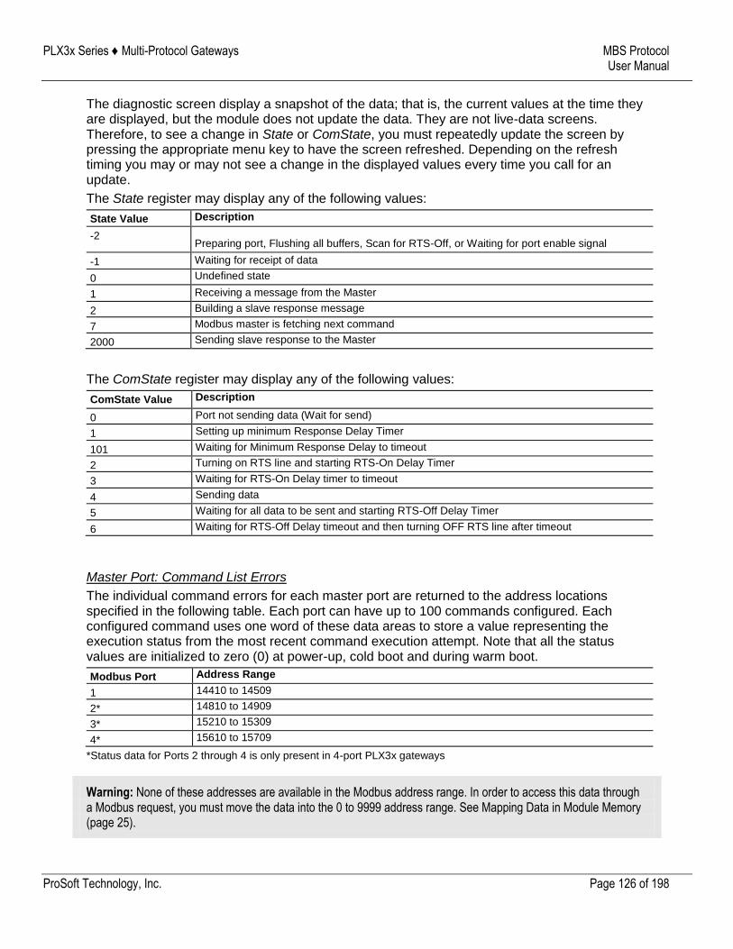
PLX3x Series ♦ Multi-Protocol Gateways MBS Protocol User Manual
ProSoft Technology, Inc. Page 126 of 198
The diagnostic screen display a snapshot of the data; that is, the current values at the time they are displayed, but the module does not update the data. They are not live-data screens. Therefore, to see a change in State or ComState, you must repeatedly update the screen by pressing the appropriate menu key to have the screen refreshed. Depending on the refresh timing you may or may not see a change in the displayed values every time you call for an update.
The State register may display any of the following values:
State Value Description
-2 Preparing port, Flushing all buffers, Scan for RTS-Off, or Waiting for port enable signal
-1 Waiting for receipt of data
0 Undefined state
1 Receiving a message from the Master
2 Building a slave response message
7 Modbus master is fetching next command
2000 Sending slave response to the Master
The ComState register may display any of the following values:
ComState Value Description
0 Port not sending data (Wait for send)
1 Setting up minimum Response Delay Timer
101 Waiting for Minimum Response Delay to timeout
2 Turning on RTS line and starting RTS-On Delay Timer
3 Waiting for RTS-On Delay timer to timeout
4 Sending data
5 Waiting for all data to be sent and starting RTS-Off Delay Timer
6 Waiting for RTS-Off Delay timeout and then turning OFF RTS line after timeout
Master Port: Command List Errors
The individual command errors for each master port are returned to the address locations specified in the following table. Each port can have up to 100 commands configured. Each configured command uses one word of these data areas to store a value representing the execution status from the most recent command execution attempt. Note that all the status values are initialized to zero (0) at power-up, cold boot and during warm boot.
Modbus Port Address Range
1 14410 to 14509
2* 14810 to 14909
3* 15210 to 15309
4* 15610 to 15709
*Status data for Ports 2 through 4 is only present in 4-port PLX3x gateways
Warning: None of these addresses are available in the Modbus address range. In order to access this data through a Modbus request, you must move the data into the 0 to 9999 address range. See Mapping Data in Module Memory (page 25).

PLX3x Series ♦ Multi-Protocol Gateways MBS Protocol User Manual
ProSoft Technology, Inc. Page 127 of 198
Port 1 Command Error List Layout
The first word in the specified register location contains the status/error code for the first command in the port's Command List. Successive words in the Command Error List are associated with corresponding commands in the list.
The addresses listed are for Port 1 only; but the format is the same for each port. See Master Port: Command List Errors (page 126) for the start address for each port.
Internal Database Address (Example)
Offset Description
14410 0 Command #1 Error Code
14411 1 Command #2 Error Code
14412 2 Command #3 Error Code
14413 3 Command #4 Error Code
14414 4 Command #5 Error Code
... ... ...
14507 97 Command #98 Error Code
14508 98 Command #99 Error Code
14509 99 Command #100 Error Code
Note that the gateway initializes the Command Error List tables to zero (0) at power-up, cold boot, and warm boot. If a command executes successfully, the value in the associated register remains at zero (0), indicating no command error was detected. Any non-zero value in this table indicates the corresponding command experienced an error.
The data in this table is dynamic and is updated each time a command is executed. Therefore, if the command fails once and succeeds on the next attempt, the error code from the previously failed attempt is overwritten with zero and be lost. Error codes are not archived in the gateway's database. To see if the port has experienced an error since the most recent restart and what the most recently occurring error was, if any, you can check the Last Error/Index.
Master Port: Modbus Slave List Status
The gateway stores Slave List Status values for each Master port in the address locations specified in the following table. Note that all the status values are initialized to zero (0) at power-up, cold boot and during warm boot.
Modbus Port Address Range
1 14510 to 14764
2* 14910 to 15164
3* 15310 to 15564
4* 15710 to 15964
*Status data for Ports 2 through 4 is only present in 4-port MBS gateways.
Warning: None of these addresses are available in the Modbus address range. In order to access this data through a Modbus request, you must move the data into the 0 to 9999 address range. See Mapping Data in Module Memory (page 25).
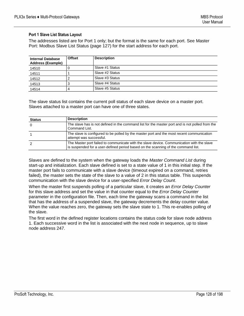
PLX3x Series ♦ Multi-Protocol Gateways MBS Protocol User Manual
ProSoft Technology, Inc. Page 128 of 198
Port 1 Slave List Status Layout
The addresses listed are for Port 1 only; but the format is the same for each port. See Master Port: Modbus Slave List Status (page 127) for the start address for each port.
Internal Database Address (Example)
Offset Description
14510 0 Slave #1 Status
14511 1 Slave #2 Status
14512 2 Slave #3 Status
14513 3 Slave #4 Status
14514 4 Slave #5 Status
The slave status list contains the current poll status of each slave device on a master port. Slaves attached to a master port can have one of three states.
Status Description
0 The slave has is not defined in the command list for the master port and is not polled from the Command List.
1 The slave is configured to be polled by the master port and the most recent communication attempt was successful.
2 The Master port failed to communicate with the slave device. Communication with the slave is suspended for a user-defined period based on the scanning of the command list.
Slaves are defined to the system when the gateway loads the Master Command List during start-up and initialization. Each slave defined is set to a state value of 1 in this initial step. If the master port fails to communicate with a slave device (timeout expired on a command, retries failed), the master sets the state of the slave to a value of 2 in this status table. This suspends communication with the slave device for a user-specified Error Delay Count.
When the master first suspends polling of a particular slave, it creates an Error Delay Counter for this slave address and set the value in that counter equal to the Error Delay Counter parameter in the configuration file. Then, each time the gateway scans a command in the list that has the address of a suspended slave, the gateway decrements the delay counter value. When the value reaches zero, the gateway sets the slave state to 1. This re-enables polling of the slave.
The first word in the defined register locations contains the status code for slave node address 1. Each successive word in the list is associated with the next node in sequence, up to slave node address 247.
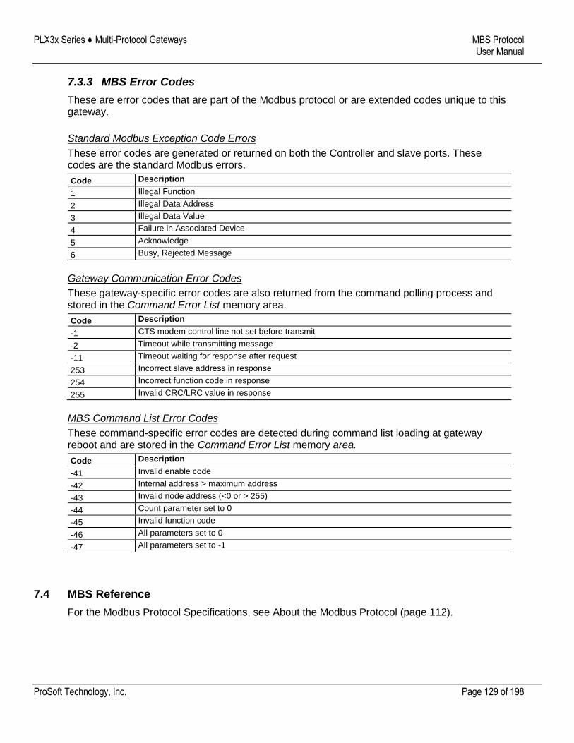
PLX3x Series ♦ Multi-Protocol Gateways MBS Protocol User Manual
ProSoft Technology, Inc. Page 129 of 198
7.3.3 MBS Error Codes
These are error codes that are part of the Modbus protocol or are extended codes unique to this gateway.
Standard Modbus Exception Code Errors
These error codes are generated or returned on both the Controller and slave ports. These codes are the standard Modbus errors.
Code Description
1 Illegal Function
2 Illegal Data Address
3 Illegal Data Value
4 Failure in Associated Device
5 Acknowledge
6 Busy, Rejected Message
Gateway Communication Error Codes
These gateway-specific error codes are also returned from the command polling process and stored in the Command Error List memory area.
Code Description
-1 CTS modem control line not set before transmit
-2 Timeout while transmitting message
-11 Timeout waiting for response after request
253 Incorrect slave address in response
254 Incorrect function code in response
255 Invalid CRC/LRC value in response
MBS Command List Error Codes
These command-specific error codes are detected during command list loading at gateway reboot and are stored in the Command Error List memory area.
Code Description
-41 Invalid enable code
-42 Internal address > maximum address
-43 Invalid node address (<0 or > 255)
-44 Count parameter set to 0
-45 Invalid function code
-46 All parameters set to 0
-47 All parameters set to -1
7.4 MBS Reference
For the Modbus Protocol Specifications, see About the Modbus Protocol (page 112).
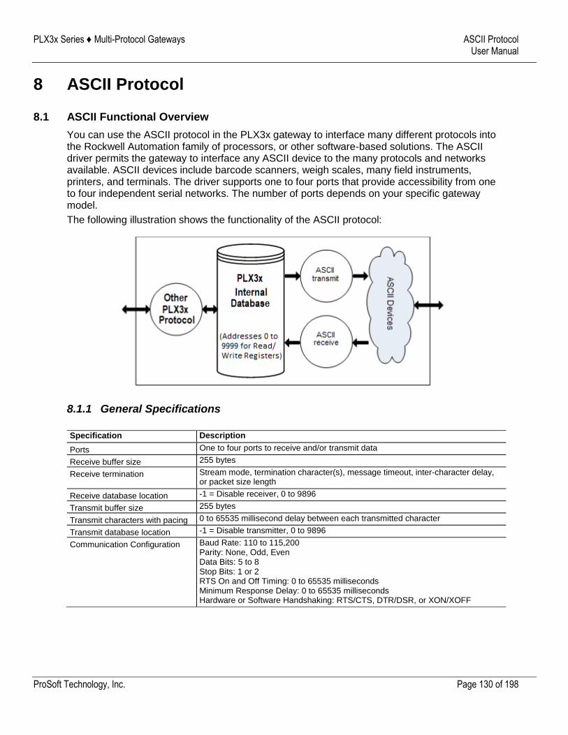
PLX3x Series ♦ Multi-Protocol Gateways ASCII Protocol User Manual
ProSoft Technology, Inc. Page 130 of 198
8 ASCII Protocol
8.1 ASCII Functional Overview
You can use the ASCII protocol in the PLX3x gateway to interface many different protocols into the Rockwell Automation family of processors, or other software-based solutions. The ASCII driver permits the gateway to interface any ASCII device to the many protocols and networks available. ASCII devices include barcode scanners, weigh scales, many field instruments, printers, and terminals. The driver supports one to four ports that provide accessibility from one to four independent serial networks. The number of ports depends on your specific gateway model.
The following illustration shows the functionality of the ASCII protocol:
8.1.1 General Specifications
Specification Description
Ports One to four ports to receive and/or transmit data
Receive buffer size 255 bytes
Receive termination Stream mode, termination character(s), message timeout, inter-character delay, or packet size length
Receive database location -1 = Disable receiver, 0 to 9896
Transmit buffer size 255 bytes
Transmit characters with pacing 0 to 65535 millisecond delay between each transmitted character
Transmit database location -1 = Disable transmitter, 0 to 9896
Communication Configuration Baud Rate: 110 to 115,200 Parity: None, Odd, Even Data Bits: 5 to 8 Stop Bits: 1 or 2 RTS On and Off Timing: 0 to 65535 milliseconds Minimum Response Delay: 0 to 65535 milliseconds Hardware or Software Handshaking: RTS/CTS, DTR/DSR, or XON/XOFF
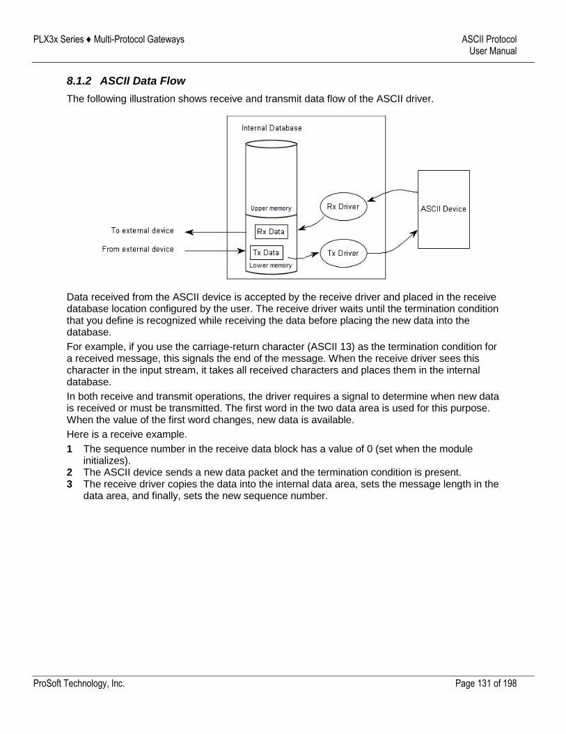
PLX3x Series ♦ Multi-Protocol Gateways ASCII Protocol User Manual
ProSoft Technology, Inc. Page 131 of 198
8.1.2 ASCII Data Flow
The following illustration shows receive and transmit data flow of the ASCII driver.
Data received from the ASCII device is accepted by the receive driver and placed in the receive database location configured by the user. The receive driver waits until the termination condition that you define is recognized while receiving the data before placing the new data into the database.
For example, if you use the carriage-return character (ASCII 13) as the termination condition for a received message, this signals the end of the message. When the receive driver sees this character in the input stream, it takes all received characters and places them in the internal database.
In both receive and transmit operations, the driver requires a signal to determine when new data is received or must be transmitted. The first word in the two data area is used for this purpose. When the value of the first word changes, new data is available.
Here is a receive example.
1 The sequence number in the receive data block has a value of 0 (set when the module initializes).
2 The ASCII device sends a new data packet and the termination condition is present. 3 The receive driver copies the data into the internal data area, sets the message length in the
data area, and finally, sets the new sequence number.
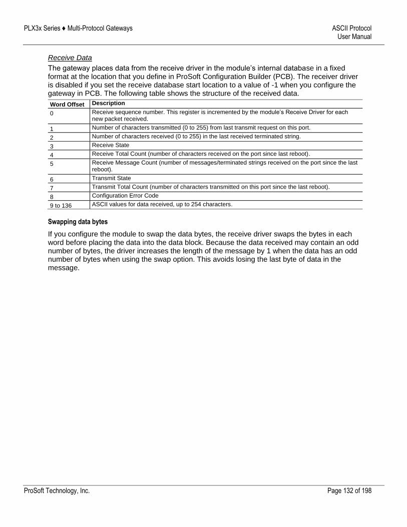
PLX3x Series ♦ Multi-Protocol Gateways ASCII Protocol User Manual
ProSoft Technology, Inc. Page 132 of 198
Receive Data
The gateway places data from the receive driver in the module’s internal database in a fixed format at the location that you define in ProSoft Configuration Builder (PCB). The receiver driver is disabled if you set the receive database start location to a value of -1 when you configure the gateway in PCB. The following table shows the structure of the received data.
Word Offset Description
0 Receive sequence number. This register is incremented by the module’s Receive Driver for each new packet received.
1 Number of characters transmitted (0 to 255) from last transmit request on this port.
2 Number of characters received (0 to 255) in the last received terminated string.
3 Receive State
4 Receive Total Count (number of characters received on the port since last reboot).
5 Receive Message Count (number of messages/terminated strings received on the port since the last reboot).
6 Transmit State
7 Transmit Total Count (number of characters transmitted on this port since the last reboot).
8 Configuration Error Code
9 to 136 ASCII values for data received, up to 254 characters.
Swapping data bytes
If you configure the module to swap the data bytes, the receive driver swaps the bytes in each word before placing the data into the data block. Because the data received may contain an odd number of bytes, the driver increases the length of the message by 1 when the data has an odd number of bytes when using the swap option. This avoids losing the last byte of data in the message.
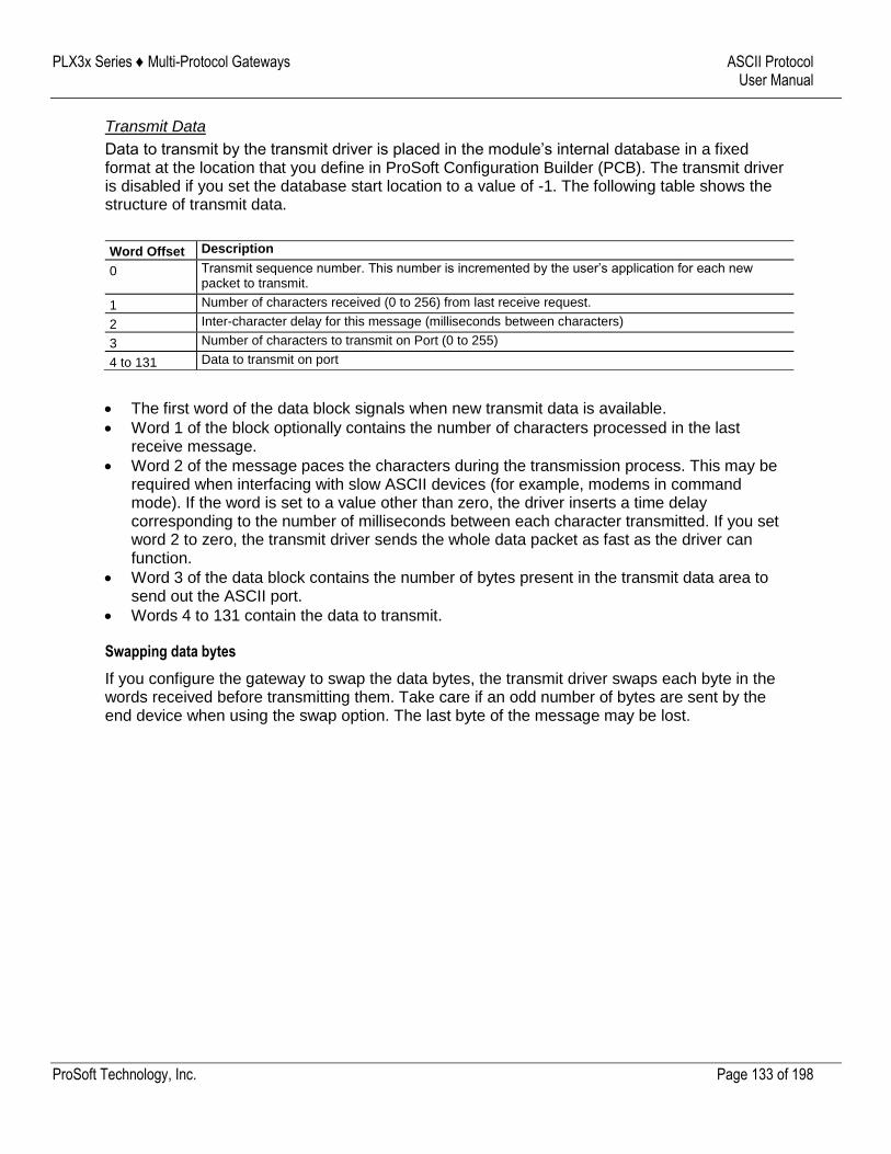
PLX3x Series ♦ Multi-Protocol Gateways ASCII Protocol User Manual
ProSoft Technology, Inc. Page 133 of 198
Transmit Data
Data to transmit by the transmit driver is placed in the module’s internal database in a fixed format at the location that you define in ProSoft Configuration Builder (PCB). The transmit driver is disabled if you set the database start location to a value of -1. The following table shows the structure of transmit data.
Word Offset Description
0 Transmit sequence number. This number is incremented by the user’s application for each new packet to transmit.
1 Number of characters received (0 to 256) from last receive request.
2 Inter-character delay for this message (milliseconds between characters)
3 Number of characters to transmit on Port (0 to 255)
4 to 131 Data to transmit on port
The first word of the data block signals when new transmit data is available.
Word 1 of the block optionally contains the number of characters processed in the last receive message.
Word 2 of the message paces the characters during the transmission process. This may be required when interfacing with slow ASCII devices (for example, modems in command mode). If the word is set to a value other than zero, the driver inserts a time delay corresponding to the number of milliseconds between each character transmitted. If you set word 2 to zero, the transmit driver sends the whole data packet as fast as the driver can function.
Word 3 of the data block contains the number of bytes present in the transmit data area to send out the ASCII port.
Words 4 to 131 contain the data to transmit.
Swapping data bytes
If you configure the gateway to swap the data bytes, the transmit driver swaps each byte in the words received before transmitting them. Take care if an odd number of bytes are sent by the end device when using the swap option. The last byte of the message may be lost.
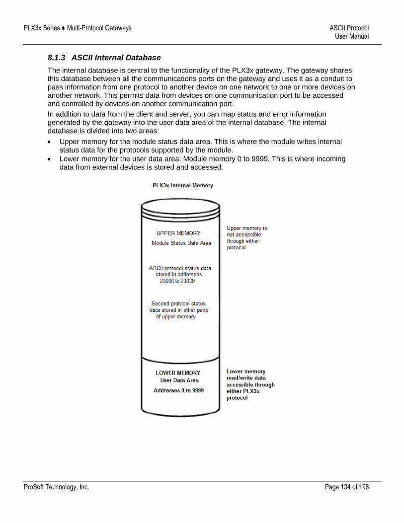
PLX3x Series ♦ Multi-Protocol Gateways ASCII Protocol User Manual
ProSoft Technology, Inc. Page 134 of 198
8.1.3 ASCII Internal Database
The internal database is central to the functionality of the PLX3x gateway. The gateway shares this database between all the communications ports on the gateway and uses it as a conduit to pass information from one protocol to another device on one network to one or more devices on another network. This permits data from devices on one communication port to be accessed and controlled by devices on another communication port.
In addition to data from the client and server, you can map status and error information generated by the gateway into the user data area of the internal database. The internal database is divided into two areas:
Upper memory for the module status data area. This is where the module writes internal status data for the protocols supported by the module.
Lower memory for the user data area: Module memory 0 to 9999. This is where incoming data from external devices is stored and accessed.
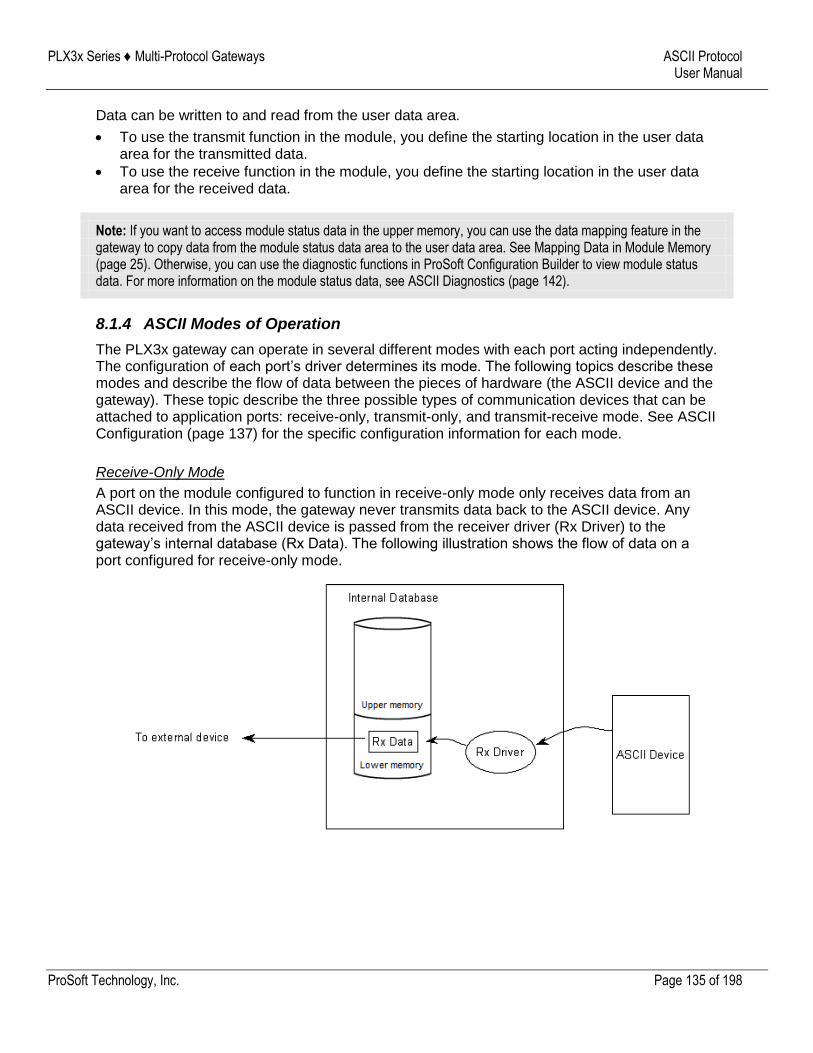
PLX3x Series ♦ Multi-Protocol Gateways ASCII Protocol User Manual
ProSoft Technology, Inc. Page 135 of 198
Data can be written to and read from the user data area.
To use the transmit function in the module, you define the starting location in the user data area for the transmitted data.
To use the receive function in the module, you define the starting location in the user data area for the received data.
Note: If you want to access module status data in the upper memory, you can use the data mapping feature in the gateway to copy data from the module status data area to the user data area. See Mapping Data in Module Memory (page 25). Otherwise, you can use the diagnostic functions in ProSoft Configuration Builder to view module status data. For more information on the module status data, see ASCII Diagnostics (page 142).
8.1.4 ASCII Modes of Operation
The PLX3x gateway can operate in several different modes with each port acting independently. The configuration of each port’s driver determines its mode. The following topics describe these modes and describe the flow of data between the pieces of hardware (the ASCII device and the gateway). These topic describe the three possible types of communication devices that can be attached to application ports: receive-only, transmit-only, and transmit-receive mode. See ASCII Configuration (page 137) for the specific configuration information for each mode.
Receive-Only Mode
A port on the module configured to function in receive-only mode only receives data from an ASCII device. In this mode, the gateway never transmits data back to the ASCII device. Any data received from the ASCII device is passed from the receiver driver (Rx Driver) to the gateway’s internal database (Rx Data). The following illustration shows the flow of data on a port configured for receive-only mode.
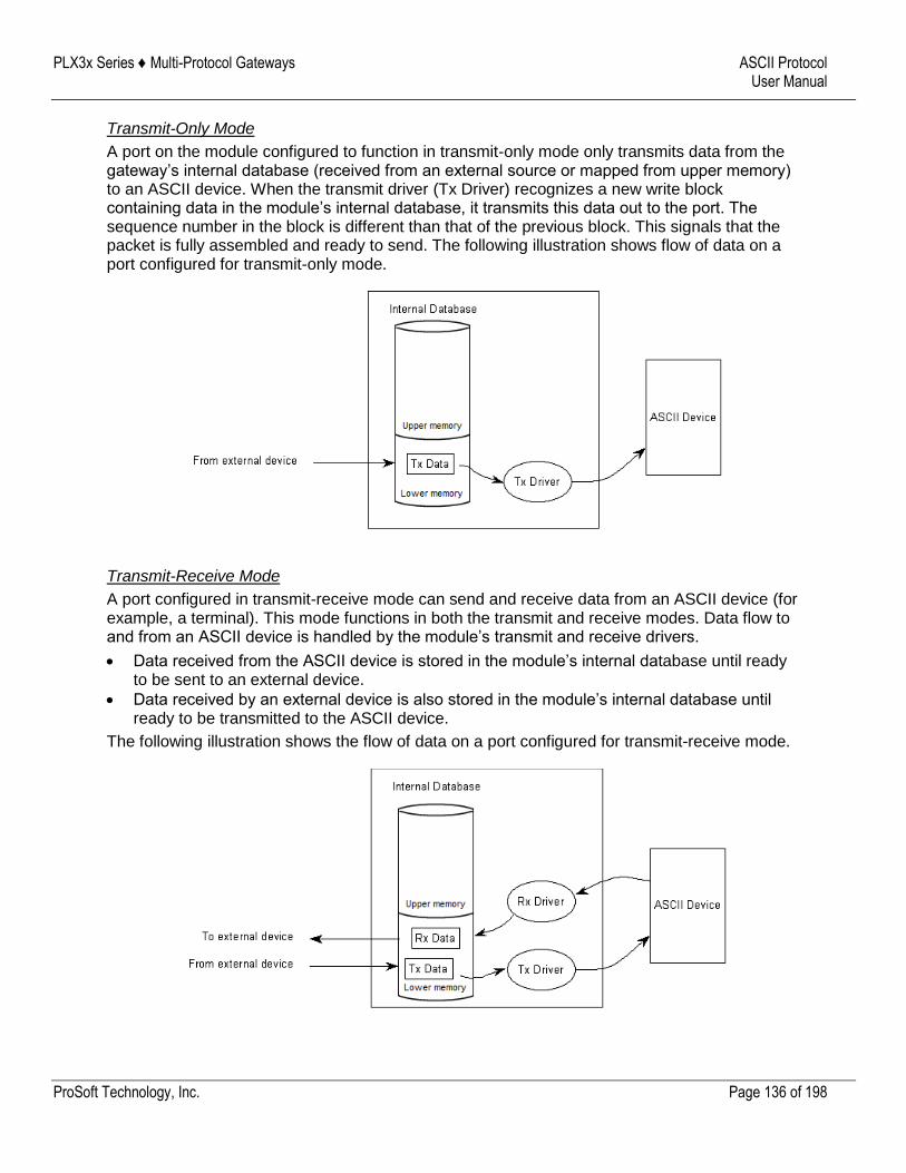
PLX3x Series ♦ Multi-Protocol Gateways ASCII Protocol User Manual
ProSoft Technology, Inc. Page 136 of 198
Transmit-Only Mode
A port on the module configured to function in transmit-only mode only transmits data from the gateway’s internal database (received from an external source or mapped from upper memory) to an ASCII device. When the transmit driver (Tx Driver) recognizes a new write block containing data in the module’s internal database, it transmits this data out to the port. The sequence number in the block is different than that of the previous block. This signals that the packet is fully assembled and ready to send. The following illustration shows flow of data on a port configured for transmit-only mode.
Transmit-Receive Mode
A port configured in transmit-receive mode can send and receive data from an ASCII device (for example, a terminal). This mode functions in both the transmit and receive modes. Data flow to and from an ASCII device is handled by the module’s transmit and receive drivers.
Data received from the ASCII device is stored in the module’s internal database until ready to be sent to an external device.
Data received by an external device is also stored in the module’s internal database until ready to be transmitted to the ASCII device.
The following illustration shows the flow of data on a port configured for transmit-receive mode.
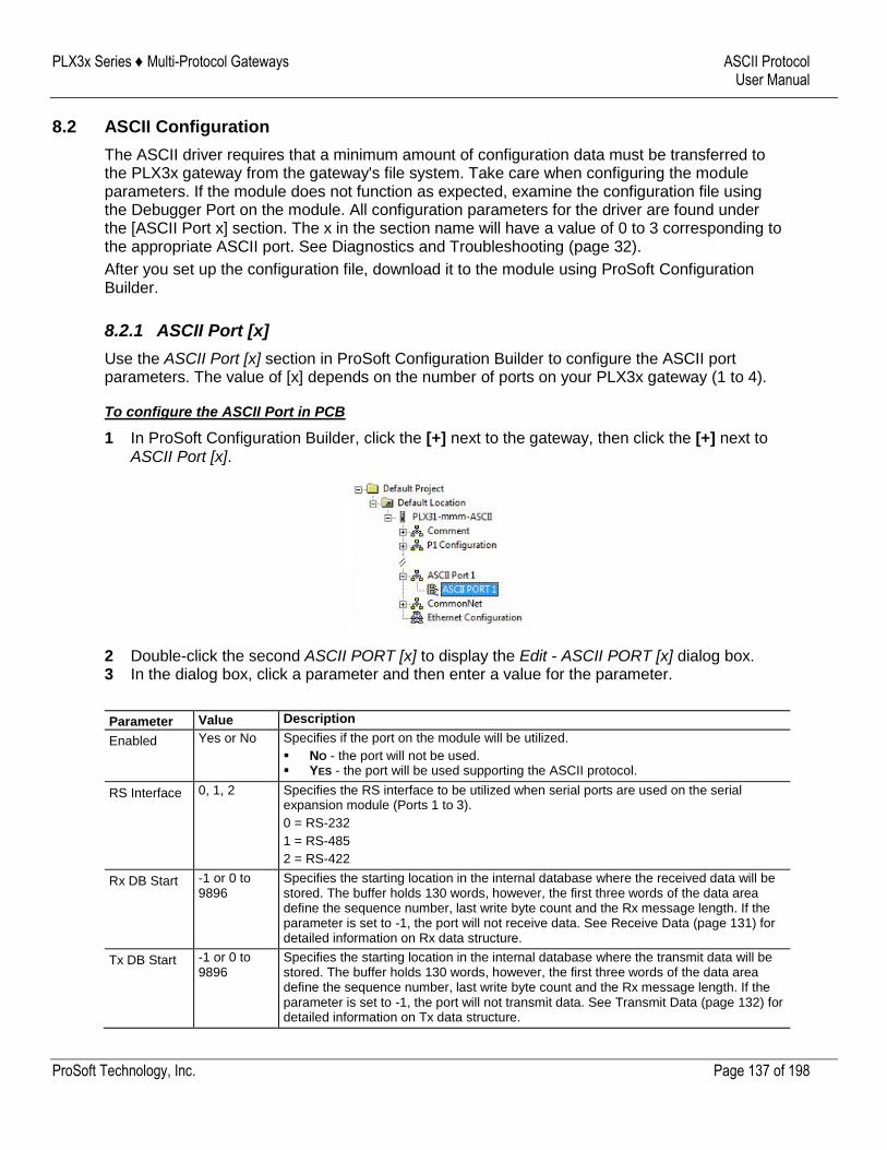
PLX3x Series ♦ Multi-Protocol Gateways ASCII Protocol User Manual
ProSoft Technology, Inc. Page 137 of 198
8.2 ASCII Configuration
The ASCII driver requires that a minimum amount of configuration data must be transferred to the PLX3x gateway from the gateway's file system. Take care when configuring the module parameters. If the module does not function as expected, examine the configuration file using the Debugger Port on the module. All configuration parameters for the driver are found under the [ASCII Port x] section. The x in the section name will have a value of 0 to 3 corresponding to the appropriate ASCII port. See Diagnostics and Troubleshooting (page 32).
After you set up the configuration file, download it to the module using ProSoft Configuration Builder.
8.2.1 ASCII Port [x]
Use the ASCII Port [x] section in ProSoft Configuration Builder to configure the ASCII port parameters. The value of [x] depends on the number of ports on your PLX3x gateway (1 to 4).
To configure the ASCII Port in PCB
1 In ProSoft Configuration Builder, click the [+] next to the gateway, then click the [+] next to ASCII Port [x].
2 Double-click the second ASCII PORT [x] to display the Edit - ASCII PORT [x] dialog box. 3 In the dialog box, click a parameter and then enter a value for the parameter.
Parameter Value Description
Enabled Yes or No Specifies if the port on the module will be utilized.
NO - the port will not be used. YES - the port will be used supporting the ASCII protocol.
RS Interface 0, 1, 2 Specifies the RS interface to be utilized when serial ports are used on the serial expansion module (Ports 1 to 3).
0 = RS-232
1 = RS-485
2 = RS-422
Rx DB Start -1 or 0 to 9896
Specifies the starting location in the internal database where the received data will be stored. The buffer holds 130 words, however, the first three words of the data area define the sequence number, last write byte count and the Rx message length. If the parameter is set to -1, the port will not receive data. See Receive Data (page 131) for detailed information on Rx data structure.
Tx DB Start -1 or 0 to 9896
Specifies the starting location in the internal database where the transmit data will be stored. The buffer holds 130 words, however, the first three words of the data area define the sequence number, last write byte count and the Rx message length. If the parameter is set to -1, the port will not transmit data. See Transmit Data (page 132) for detailed information on Tx data structure.
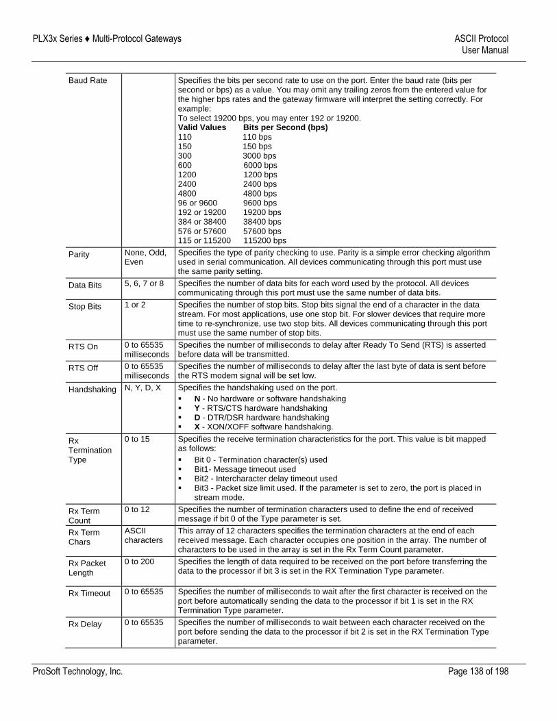
PLX3x Series ♦ Multi-Protocol Gateways ASCII Protocol User Manual
ProSoft Technology, Inc. Page 138 of 198
Baud Rate Specifies the bits per second rate to use on the port. Enter the baud rate (bits per second or bps) as a value. You may omit any trailing zeros from the entered value for the higher bps rates and the gateway firmware will interpret the setting correctly. For example: To select 19200 bps, you may enter 192 or 19200. Valid Values Bits per Second (bps)
110 110 bps 150 150 bps 300 3000 bps 600 6000 bps 1200 1200 bps 2400 2400 bps 4800 4800 bps 96 or 9600 9600 bps 192 or 19200 19200 bps 384 or 38400 38400 bps 576 or 57600 57600 bps 115 or 115200 115200 bps
Parity None, Odd, Even
Specifies the type of parity checking to use. Parity is a simple error checking algorithm used in serial communication. All devices communicating through this port must use the same parity setting.
Data Bits 5, 6, 7 or 8 Specifies the number of data bits for each word used by the protocol. All devices communicating through this port must use the same number of data bits.
Stop Bits 1 or 2 Specifies the number of stop bits. Stop bits signal the end of a character in the data stream. For most applications, use one stop bit. For slower devices that require more time to re-synchronize, use two stop bits. All devices communicating through this port must use the same number of stop bits.
RTS On 0 to 65535 milliseconds
Specifies the number of milliseconds to delay after Ready To Send (RTS) is asserted before data will be transmitted.
RTS Off 0 to 65535 milliseconds
Specifies the number of milliseconds to delay after the last byte of data is sent before the RTS modem signal will be set low.
Handshaking N, Y, D, X Specifies the handshaking used on the port.
N - No hardware or software handshaking Y - RTS/CTS hardware handshaking D - DTR/DSR hardware handshaking X - XON/XOFF software handshaking.
Rx Termination Type
0 to 15 Specifies the receive termination characteristics for the port. This value is bit mapped as follows:
Bit 0 - Termination character(s) used Bit1- Message timeout used Bit2 - Intercharacter delay timeout used Bit3 - Packet size limit used. If the parameter is set to zero, the port is placed in
stream mode.
Rx Term Count
0 to 12 Specifies the number of termination characters used to define the end of received message if bit 0 of the Type parameter is set.
Rx Term Chars
ASCII characters
This array of 12 characters specifies the termination characters at the end of each received message. Each character occupies one position in the array. The number of characters to be used in the array is set in the Rx Term Count parameter.
Rx Packet Length
0 to 200 Specifies the length of data required to be received on the port before transferring the data to the processor if bit 3 is set in the RX Termination Type parameter.
Rx Timeout 0 to 65535 Specifies the number of milliseconds to wait after the first character is received on the port before automatically sending the data to the processor if bit 1 is set in the RX Termination Type parameter.
Rx Delay 0 to 65535 Specifies the number of milliseconds to wait between each character received on the port before sending the data to the processor if bit 2 is set in the RX Termination Type parameter.
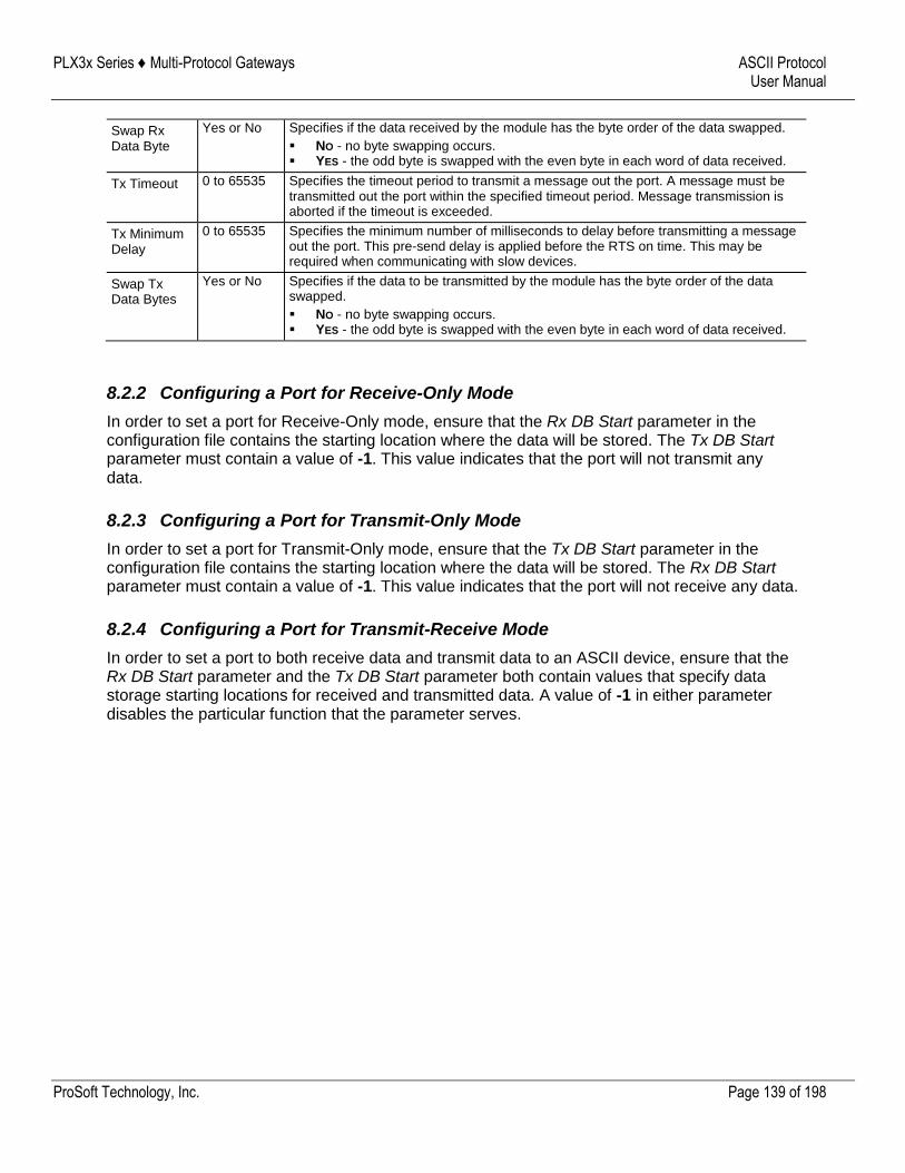
PLX3x Series ♦ Multi-Protocol Gateways ASCII Protocol User Manual
ProSoft Technology, Inc. Page 139 of 198
Swap Rx Data Byte
Yes or No Specifies if the data received by the module has the byte order of the data swapped.
NO - no byte swapping occurs. YES - the odd byte is swapped with the even byte in each word of data received.
Tx Timeout 0 to 65535 Specifies the timeout period to transmit a message out the port. A message must be transmitted out the port within the specified timeout period. Message transmission is aborted if the timeout is exceeded.
Tx Minimum Delay
0 to 65535 Specifies the minimum number of milliseconds to delay before transmitting a message out the port. This pre-send delay is applied before the RTS on time. This may be required when communicating with slow devices.
Swap Tx Data Bytes
Yes or No Specifies if the data to be transmitted by the module has the byte order of the data swapped.
NO - no byte swapping occurs. YES - the odd byte is swapped with the even byte in each word of data received.
8.2.2 Configuring a Port for Receive-Only Mode
In order to set a port for Receive-Only mode, ensure that the Rx DB Start parameter in the configuration file contains the starting location where the data will be stored. The Tx DB Start parameter must contain a value of -1. This value indicates that the port will not transmit any data.
8.2.3 Configuring a Port for Transmit-Only Mode
In order to set a port for Transmit-Only mode, ensure that the Tx DB Start parameter in the configuration file contains the starting location where the data will be stored. The Rx DB Start parameter must contain a value of -1. This value indicates that the port will not receive any data.
8.2.4 Configuring a Port for Transmit-Receive Mode
In order to set a port to both receive data and transmit data to an ASCII device, ensure that the Rx DB Start parameter and the Tx DB Start parameter both contain values that specify data storage starting locations for received and transmitted data. A value of -1 in either parameter disables the particular function that the parameter serves.
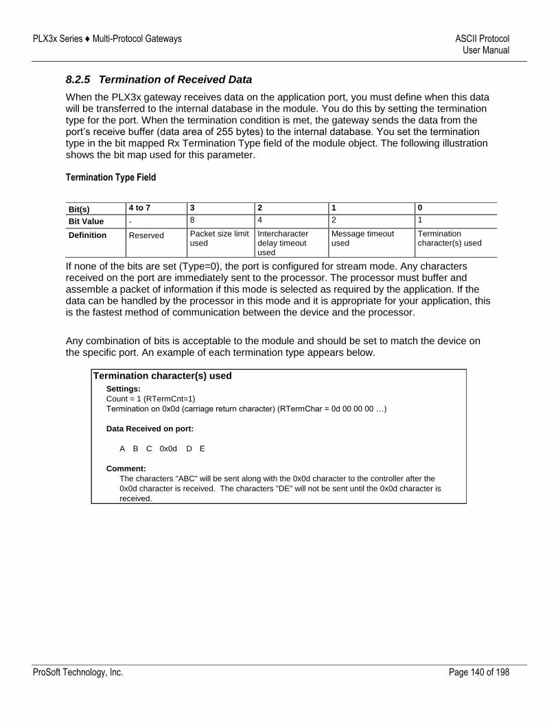
PLX3x Series ♦ Multi-Protocol Gateways ASCII Protocol User Manual
ProSoft Technology, Inc. Page 140 of 198
8.2.5 Termination of Received Data
When the PLX3x gateway receives data on the application port, you must define when this data will be transferred to the internal database in the module. You do this by setting the termination type for the port. When the termination condition is met, the gateway sends the data from the port’s receive buffer (data area of 255 bytes) to the internal database. You set the termination type in the bit mapped Rx Termination Type field of the module object. The following illustration shows the bit map used for this parameter.
Termination Type Field
Bit(s) 4 to 7 3 2 1 0
Bit Value - 8 4 2 1
Definition Reserved Packet size limit used
Intercharacter delay timeout used
Message timeout used
Termination character(s) used
If none of the bits are set (Type=0), the port is configured for stream mode. Any characters received on the port are immediately sent to the processor. The processor must buffer and assemble a packet of information if this mode is selected as required by the application. If the data can be handled by the processor in this mode and it is appropriate for your application, this is the fastest method of communication between the device and the processor.
Any combination of bits is acceptable to the module and should be set to match the device on the specific port. An example of each termination type appears below.
Termination character(s) used
Settings:
Count = 1 (RTermCnt=1)
Termination on 0x0d (carriage return character) (RTermChar = 0d 00 00 00 …)
Data Received on port:
A B C 0x0d D E
Comment:
The characters "ABC" will be sent along with the 0x0d character to the controller after the
0x0d character is received. The characters "DE" will not be sent until the 0x0d character is
received.
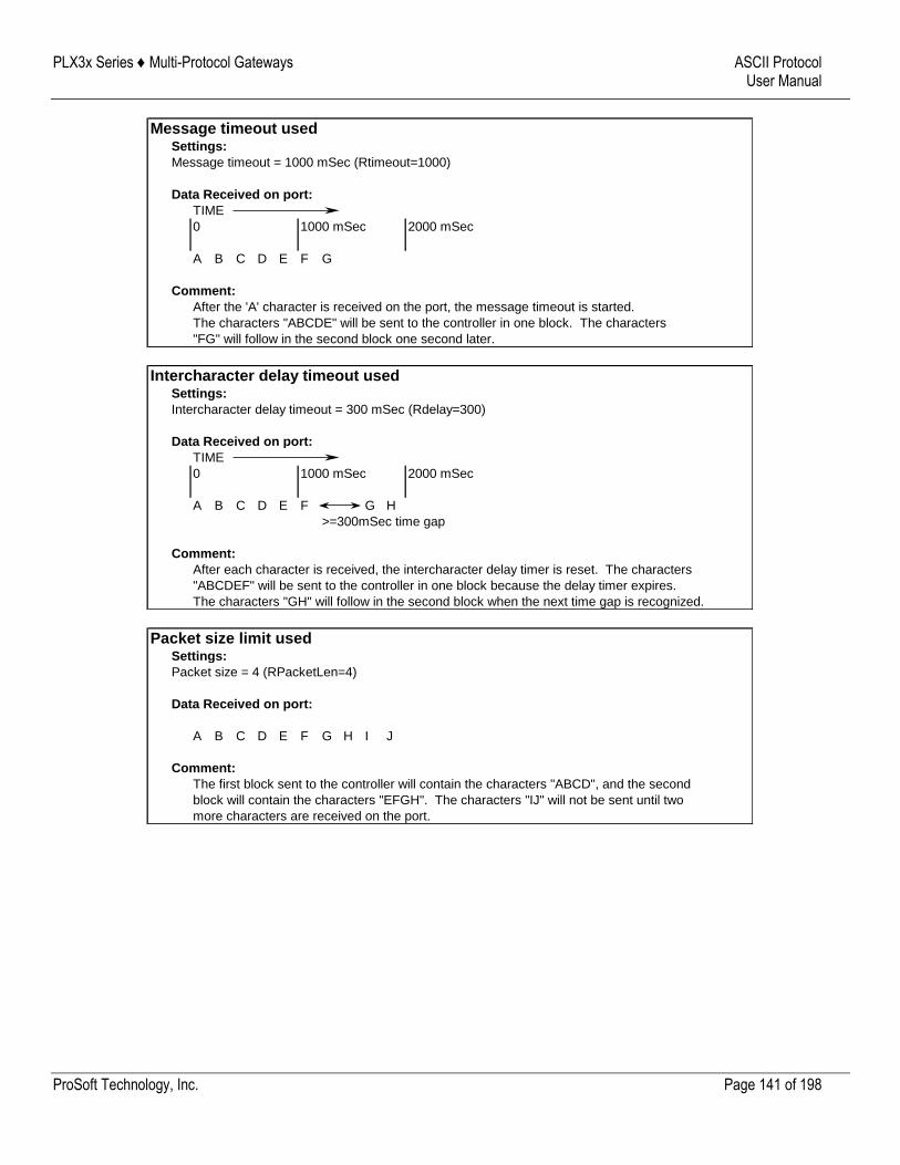
PLX3x Series ♦ Multi-Protocol Gateways ASCII Protocol User Manual
ProSoft Technology, Inc. Page 141 of 198
Message timeout usedSettings:
Message timeout = 1000 mSec (Rtimeout=1000)
Data Received on port:
TIME
0 1000 mSec 2000 mSec
A B C D E F G
Comment:
After the 'A' character is received on the port, the message timeout is started.
The characters "ABCDE" will be sent to the controller in one block. The characters
"FG" will follow in the second block one second later.
Intercharacter delay timeout usedSettings:
Intercharacter delay timeout = 300 mSec (Rdelay=300)
Data Received on port:
TIME
0 1000 mSec 2000 mSec
A B C D E F G H
>=300mSec time gap
Comment:
After each character is received, the intercharacter delay timer is reset. The characters
"ABCDEF" will be sent to the controller in one block because the delay timer expires.
The characters "GH" will follow in the second block when the next time gap is recognized.
Packet size limit usedSettings:
Packet size = 4 (RPacketLen=4)
Data Received on port:
A B C D E F G H I J
Comment:
The first block sent to the controller will contain the characters "ABCD", and the second
block will contain the characters "EFGH". The characters "IJ" will not be sent until two
more characters are received on the port.
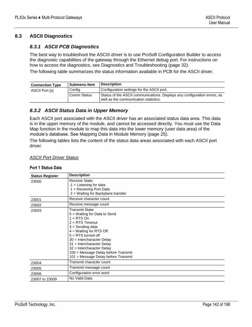
PLX3x Series ♦ Multi-Protocol Gateways ASCII Protocol User Manual
ProSoft Technology, Inc. Page 142 of 198
8.3 ASCII Diagnostics
8.3.1 ASCII PCB Diagnostics
The best way to troubleshoot the ASCIII driver is to use ProSoft Configuration Builder to access the diagnostic capabilities of the gateway through the Ethernet debug port. For instructions on how to access the diagnostics, see Diagnostics and Troubleshooting (page 32).
The following table summarizes the status information available in PCB for the ASCII driver.
Connection Type Submenu Item Description
ASCII Port [x] Config Configuration settings for the ASCII port.
Comm Status Status of the ASCII communications. Displays any configuration errors, as well as the communication statistics.
8.3.2 ASCII Status Data in Upper Memory
Each ASCII port associated with the ASCII driver has an associated status data area. This data is in the upper memory of the module, and cannot be accessed directly. You must use the Data Map function in the module to map this data into the lower memory (user data area) of the module’s database. See Mapping Data in Module Memory (page 25).
The following tables lists the content of the status data areas associated with each ASCII port driver.
ASCII Port Driver Status
Port 1 Status Data
Status Register Description
23000 Receive State: -1 = Listening for data 1 = Receiving Port Data 2 = Waiting for Backplane transfer
23001 Receive character count
23002 Receive message count
23003 Transmit State: 0 = Waiting for Data to Send 1 = RTS On 2 = RTS Timeout 3 = Sending data 4 = Waiting for RTS Off 5 = RTS turned off 30 = Intercharacter Delay 31 = Intercharacter Delay 32 = Intercharacter Delay 100 = Message Delay before Transmit 101 = Message Delay before Transmit
23004 Transmit character count
23005 Transmit message count
23006 Configuration error word
23007 to 23009 No Valid Data
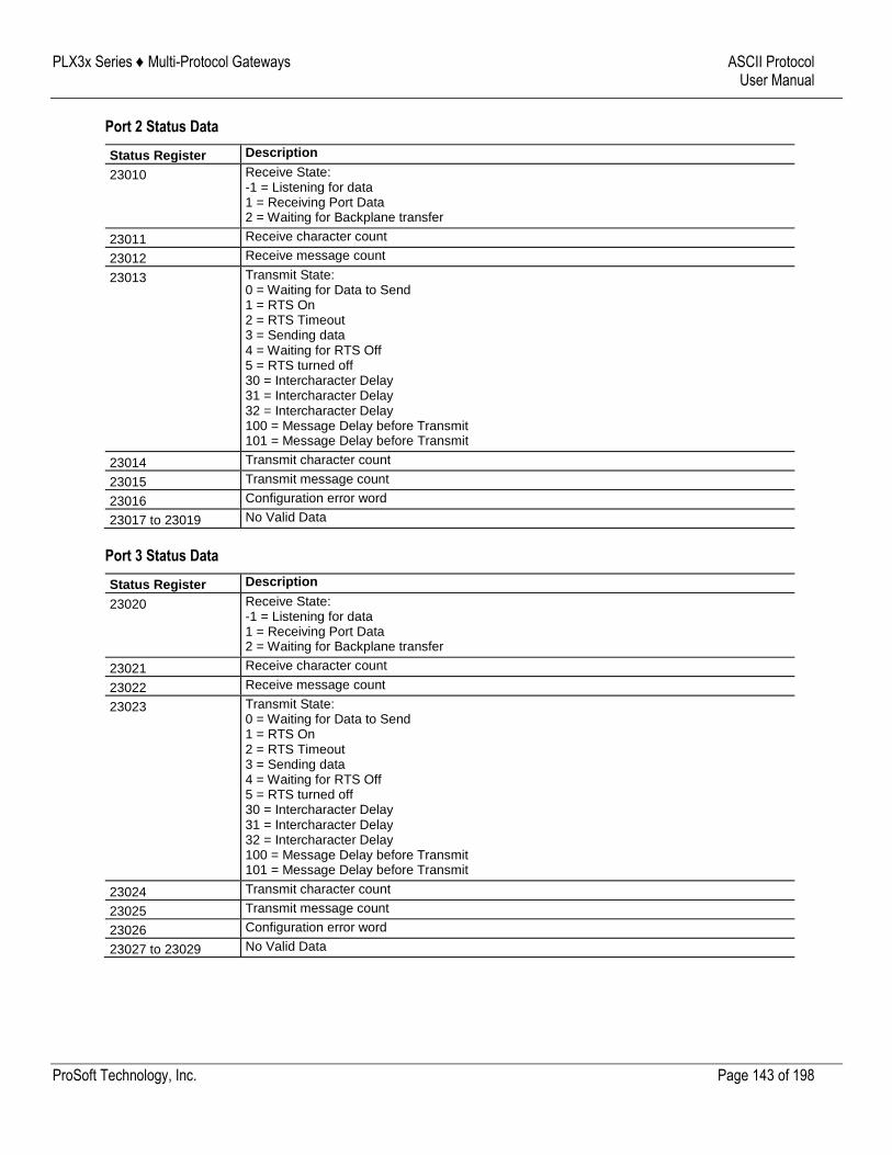
PLX3x Series ♦ Multi-Protocol Gateways ASCII Protocol User Manual
ProSoft Technology, Inc. Page 143 of 198
Port 2 Status Data
Status Register Description
23010 Receive State: -1 = Listening for data 1 = Receiving Port Data 2 = Waiting for Backplane transfer
23011 Receive character count
23012 Receive message count
23013 Transmit State: 0 = Waiting for Data to Send 1 = RTS On 2 = RTS Timeout 3 = Sending data 4 = Waiting for RTS Off 5 = RTS turned off 30 = Intercharacter Delay 31 = Intercharacter Delay 32 = Intercharacter Delay 100 = Message Delay before Transmit 101 = Message Delay before Transmit
23014 Transmit character count
23015 Transmit message count
23016 Configuration error word
23017 to 23019 No Valid Data
Port 3 Status Data
Status Register Description
23020 Receive State: -1 = Listening for data 1 = Receiving Port Data 2 = Waiting for Backplane transfer
23021 Receive character count
23022 Receive message count
23023 Transmit State: 0 = Waiting for Data to Send 1 = RTS On 2 = RTS Timeout 3 = Sending data 4 = Waiting for RTS Off 5 = RTS turned off 30 = Intercharacter Delay 31 = Intercharacter Delay 32 = Intercharacter Delay 100 = Message Delay before Transmit 101 = Message Delay before Transmit
23024 Transmit character count
23025 Transmit message count
23026 Configuration error word
23027 to 23029 No Valid Data
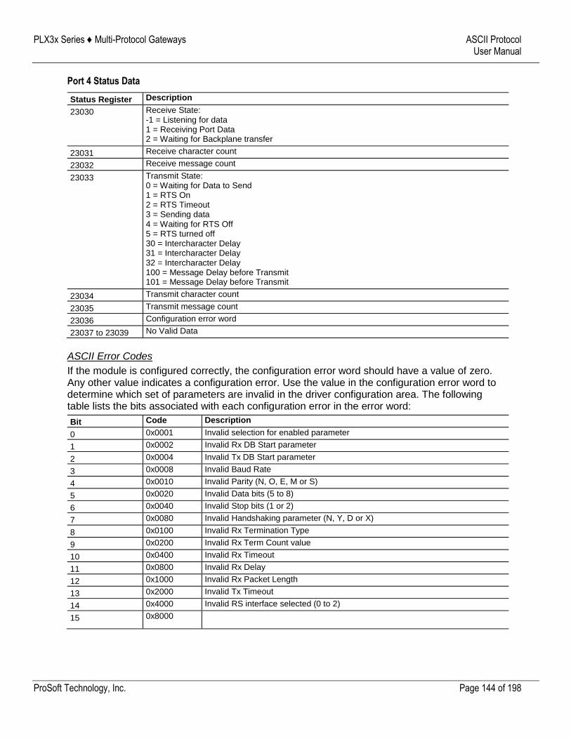
PLX3x Series ♦ Multi-Protocol Gateways ASCII Protocol User Manual
ProSoft Technology, Inc. Page 144 of 198
Port 4 Status Data
Status Register Description
23030 Receive State: -1 = Listening for data 1 = Receiving Port Data 2 = Waiting for Backplane transfer
23031 Receive character count
23032 Receive message count
23033 Transmit State: 0 = Waiting for Data to Send 1 = RTS On 2 = RTS Timeout 3 = Sending data 4 = Waiting for RTS Off 5 = RTS turned off 30 = Intercharacter Delay 31 = Intercharacter Delay 32 = Intercharacter Delay 100 = Message Delay before Transmit 101 = Message Delay before Transmit
23034 Transmit character count
23035 Transmit message count
23036 Configuration error word
23037 to 23039 No Valid Data
ASCII Error Codes
If the module is configured correctly, the configuration error word should have a value of zero. Any other value indicates a configuration error. Use the value in the configuration error word to determine which set of parameters are invalid in the driver configuration area. The following table lists the bits associated with each configuration error in the error word:
Bit Code Description
0 0x0001 Invalid selection for enabled parameter
1 0x0002 Invalid Rx DB Start parameter
2 0x0004 Invalid Tx DB Start parameter
3 0x0008 Invalid Baud Rate
4 0x0010 Invalid Parity (N, O, E, M or S)
5 0x0020 Invalid Data bits (5 to 8)
6 0x0040 Invalid Stop bits (1 or 2)
7 0x0080 Invalid Handshaking parameter (N, Y, D or X)
8 0x0100 Invalid Rx Termination Type
9 0x0200 Invalid Rx Term Count value
10 0x0400 Invalid Rx Timeout
11 0x0800 Invalid Rx Delay
12 0x1000 Invalid Rx Packet Length
13 0x2000 Invalid Tx Timeout
14 0x4000 Invalid RS interface selected (0 to 2)
15 0x8000
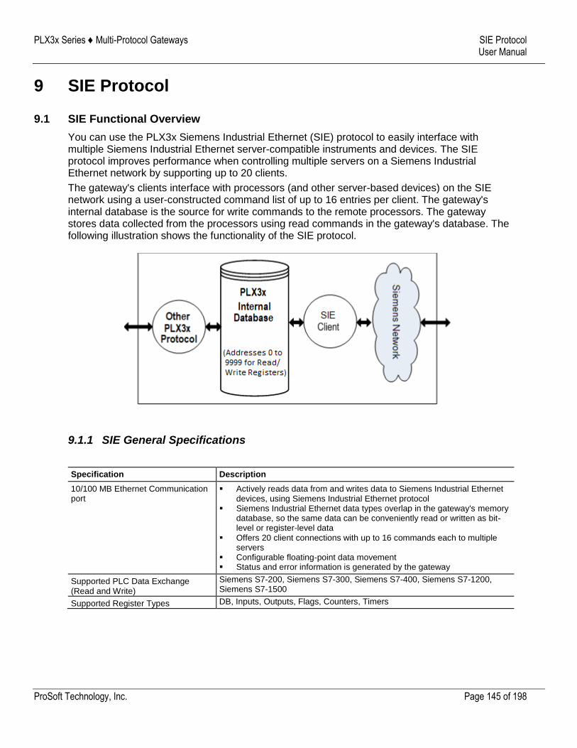
PLX3x Series ♦ Multi-Protocol Gateways SIE Protocol User Manual
ProSoft Technology, Inc. Page 145 of 198
9 SIE Protocol
9.1 SIE Functional Overview
You can use the PLX3x Siemens Industrial Ethernet (SIE) protocol to easily interface with multiple Siemens Industrial Ethernet server-compatible instruments and devices. The SIE protocol improves performance when controlling multiple servers on a Siemens Industrial Ethernet network by supporting up to 20 clients.
The gateway's clients interface with processors (and other server-based devices) on the SIE network using a user-constructed command list of up to 16 entries per client. The gateway's internal database is the source for write commands to the remote processors. The gateway stores data collected from the processors using read commands in the gateway's database. The following illustration shows the functionality of the SIE protocol.
9.1.1 SIE General Specifications
Specification Description
10/100 MB Ethernet Communication port
Actively reads data from and writes data to Siemens Industrial Ethernet devices, using Siemens Industrial Ethernet protocol
Siemens Industrial Ethernet data types overlap in the gateway's memory database, so the same data can be conveniently read or written as bit-level or register-level data
Offers 20 client connections with up to 16 commands each to multiple servers
Configurable floating-point data movement Status and error information is generated by the gateway
Supported PLC Data Exchange (Read and Write)
Siemens S7-200, Siemens S7-300, Siemens S7-400, Siemens S7-1200, Siemens S7-1500
Supported Register Types DB, Inputs, Outputs, Flags, Counters, Timers
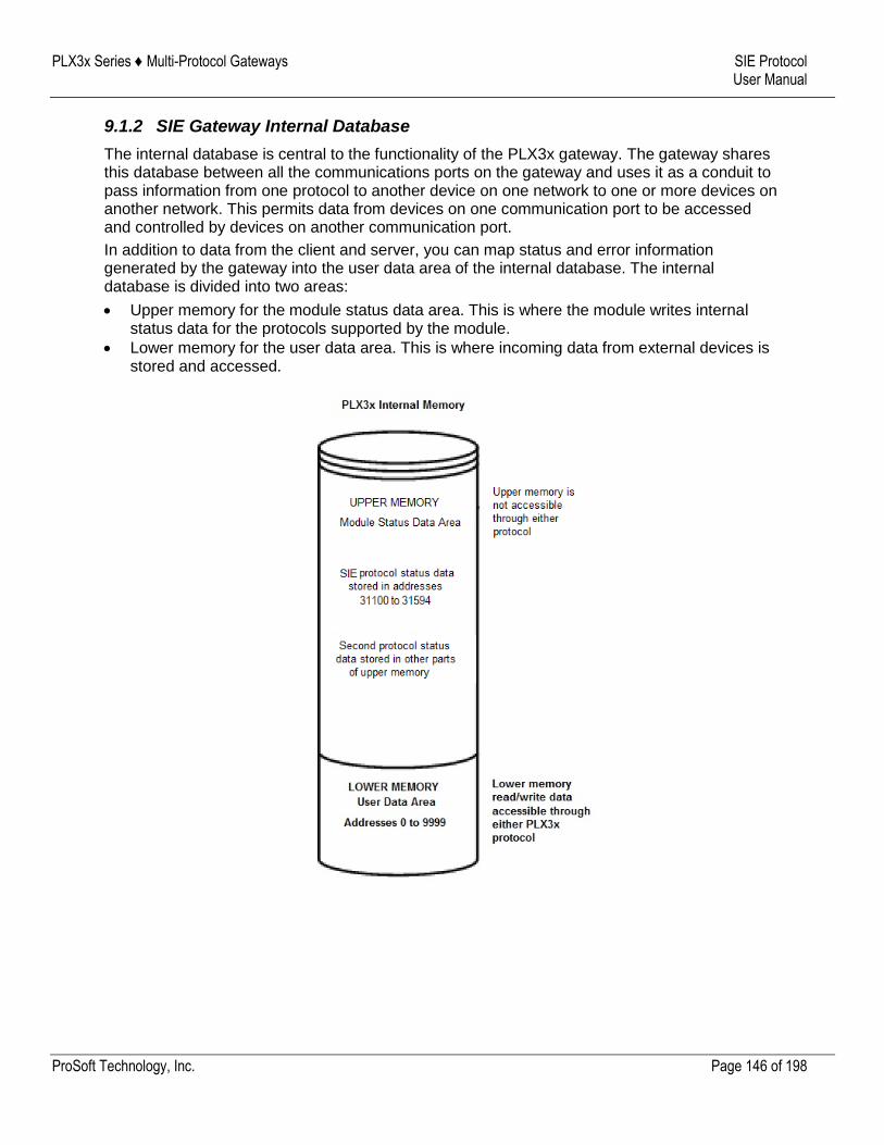
PLX3x Series ♦ Multi-Protocol Gateways SIE Protocol User Manual
ProSoft Technology, Inc. Page 146 of 198
9.1.2 SIE Gateway Internal Database
The internal database is central to the functionality of the PLX3x gateway. The gateway shares this database between all the communications ports on the gateway and uses it as a conduit to pass information from one protocol to another device on one network to one or more devices on another network. This permits data from devices on one communication port to be accessed and controlled by devices on another communication port.
In addition to data from the client and server, you can map status and error information generated by the gateway into the user data area of the internal database. The internal database is divided into two areas:
Upper memory for the module status data area. This is where the module writes internal status data for the protocols supported by the module.
Lower memory for the user data area. This is where incoming data from external devices is stored and accessed.
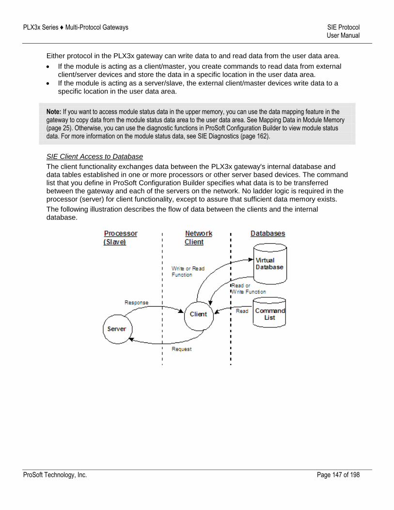
PLX3x Series ♦ Multi-Protocol Gateways SIE Protocol User Manual
ProSoft Technology, Inc. Page 147 of 198
Either protocol in the PLX3x gateway can write data to and read data from the user data area.
If the module is acting as a client/master, you create commands to read data from external client/server devices and store the data in a specific location in the user data area.
If the module is acting as a server/slave, the external client/master devices write data to a specific location in the user data area.
Note: If you want to access module status data in the upper memory, you can use the data mapping feature in the gateway to copy data from the module status data area to the user data area. See Mapping Data in Module Memory (page 25). Otherwise, you can use the diagnostic functions in ProSoft Configuration Builder to view module status data. For more information on the module status data, see SIE Diagnostics (page 162).
SIE Client Access to Database
The client functionality exchanges data between the PLX3x gateway's internal database and data tables established in one or more processors or other server based devices. The command list that you define in ProSoft Configuration Builder specifies what data is to be transferred between the gateway and each of the servers on the network. No ladder logic is required in the processor (server) for client functionality, except to assure that sufficient data memory exists.
The following illustration describes the flow of data between the clients and the internal database.

PLX3x Series ♦ Multi-Protocol Gateways SIE Protocol User Manual
ProSoft Technology, Inc. Page 148 of 198
9.2 Configuration
9.2.1 Configuring SIE Client [x] Connection
Use the SIE Client [x] section in ProSoft Configuration Builder to configure the SIE Client [x] parameters. The value of [x] depends on the number of ports on your PLX3x gateway (1 to 4).
To configure the ASCII Port in PCB
1 In ProSoft Configuration Builder, click the [+] next to the gateway, then click the [+] next to SIE Client [x].
2 Double-click the second SIE Client [x] to display the Edit - SIE Client [x] dialog box. 3 In the dialog box, click a parameter and then enter a value for the parameter. The following
table defines the configuration parameters for the SIE client (master):
Parameter Value Description
Minimum Command Delay
0 to 65535 Specifies the number of milliseconds to wait between the initial issuances of a command. This parameter can be used to delay all commands sent to servers to avoid "flooding" commands on the network. This parameter does not affect retries of a command as they will be issued when failure is recognized.
Response Timeout 0 to 65535 Specifies the time in milliseconds that a Client will wait before re-transmitting a command if no response is received from the addressed server. The value to use depends on the type of communication network used, and the expected response time of the slowest device on the network.
Retry Count 0 to 65535 Specifies the number of times a command will be retried if it fails.
Command Error Delay
0 to 300 Number of intervals to wait after command error (in seconds).
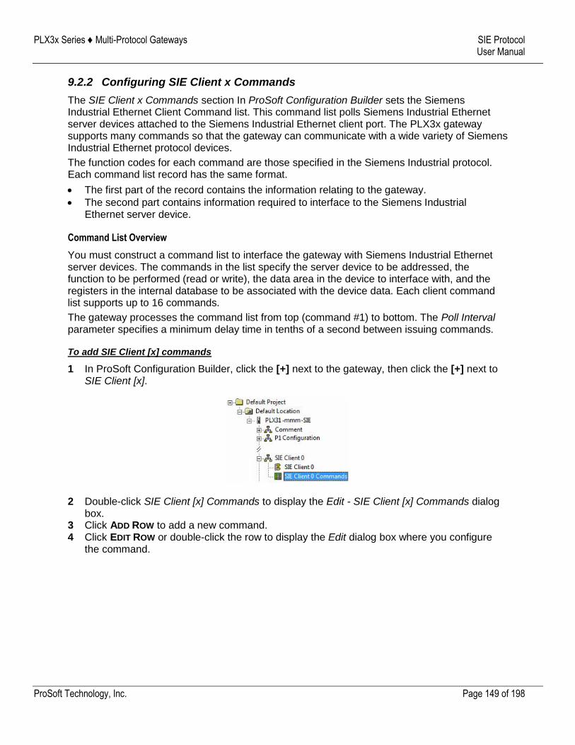
PLX3x Series ♦ Multi-Protocol Gateways SIE Protocol User Manual
ProSoft Technology, Inc. Page 149 of 198
9.2.2 Configuring SIE Client x Commands
The SIE Client x Commands section In ProSoft Configuration Builder sets the Siemens Industrial Ethernet Client Command list. This command list polls Siemens Industrial Ethernet server devices attached to the Siemens Industrial Ethernet client port. The PLX3x gateway supports many commands so that the gateway can communicate with a wide variety of Siemens Industrial Ethernet protocol devices.
The function codes for each command are those specified in the Siemens Industrial protocol. Each command list record has the same format.
The first part of the record contains the information relating to the gateway.
The second part contains information required to interface to the Siemens Industrial Ethernet server device.
Command List Overview
You must construct a command list to interface the gateway with Siemens Industrial Ethernet server devices. The commands in the list specify the server device to be addressed, the function to be performed (read or write), the data area in the device to interface with, and the registers in the internal database to be associated with the device data. Each client command list supports up to 16 commands.
The gateway processes the command list from top (command #1) to bottom. The Poll Interval parameter specifies a minimum delay time in tenths of a second between issuing commands.
To add SIE Client [x] commands
1 In ProSoft Configuration Builder, click the [+] next to the gateway, then click the [+] next to SIE Client [x].
2 Double-click SIE Client [x] Commands to display the Edit - SIE Client [x] Commands dialog box.
3 Click ADD ROW to add a new command. 4 Click EDIT ROW or double-click the row to display the Edit dialog box where you configure
the command.
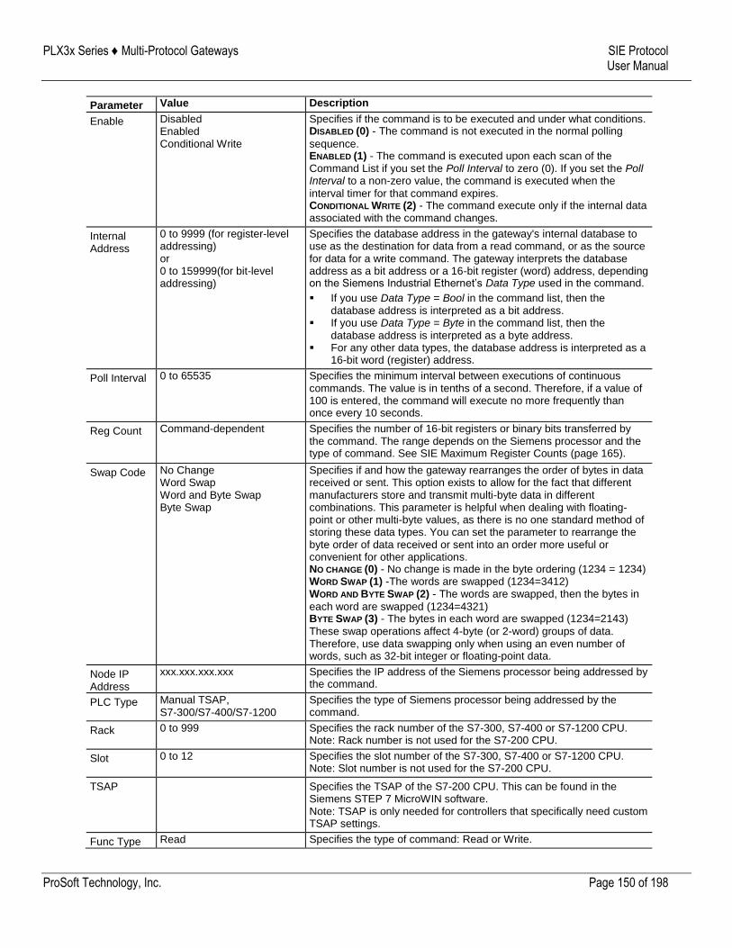
PLX3x Series ♦ Multi-Protocol Gateways SIE Protocol User Manual
ProSoft Technology, Inc. Page 150 of 198
Parameter Value Description
Enable Disabled Enabled Conditional Write
Specifies if the command is to be executed and under what conditions. DISABLED (0) - The command is not executed in the normal polling
sequence. ENABLED (1) - The command is executed upon each scan of the Command List if you set the Poll Interval to zero (0). If you set the Poll Interval to a non-zero value, the command is executed when the
interval timer for that command expires. CONDITIONAL WRITE (2) - The command execute only if the internal data associated with the command changes.
Internal Address
0 to 9999 (for register-level addressing) or 0 to 159999(for bit-level addressing)
Specifies the database address in the gateway's internal database to use as the destination for data from a read command, or as the source for data for a write command. The gateway interprets the database address as a bit address or a 16-bit register (word) address, depending on the Siemens Industrial Ethernet’s Data Type used in the command.
If you use Data Type = Bool in the command list, then the database address is interpreted as a bit address.
If you use Data Type = Byte in the command list, then the database address is interpreted as a byte address.
For any other data types, the database address is interpreted as a 16-bit word (register) address.
Poll Interval 0 to 65535 Specifies the minimum interval between executions of continuous commands. The value is in tenths of a second. Therefore, if a value of 100 is entered, the command will execute no more frequently than once every 10 seconds.
Reg Count Command-dependent Specifies the number of 16-bit registers or binary bits transferred by the command. The range depends on the Siemens processor and the type of command. See SIE Maximum Register Counts (page 165).
Swap Code No Change Word Swap Word and Byte Swap Byte Swap
Specifies if and how the gateway rearranges the order of bytes in data received or sent. This option exists to allow for the fact that different manufacturers store and transmit multi-byte data in different combinations. This parameter is helpful when dealing with floating-point or other multi-byte values, as there is no one standard method of storing these data types. You can set the parameter to rearrange the byte order of data received or sent into an order more useful or convenient for other applications. NO CHANGE (0) - No change is made in the byte ordering (1234 = 1234) WORD SWAP (1) -The words are swapped (1234=3412) WORD AND BYTE SWAP (2) - The words are swapped, then the bytes in
each word are swapped (1234=4321) BYTE SWAP (3) - The bytes in each word are swapped (1234=2143)
These swap operations affect 4-byte (or 2-word) groups of data. Therefore, use data swapping only when using an even number of words, such as 32-bit integer or floating-point data.
Node IP Address
xxx.xxx.xxx.xxx Specifies the IP address of the Siemens processor being addressed by the command.
PLC Type Manual TSAP, S7-300/S7-400/S7-1200
Specifies the type of Siemens processor being addressed by the command.
Rack 0 to 999 Specifies the rack number of the S7-300, S7-400 or S7-1200 CPU. Note: Rack number is not used for the S7-200 CPU.
Slot 0 to 12 Specifies the slot number of the S7-300, S7-400 or S7-1200 CPU. Note: Slot number is not used for the S7-200 CPU.
TSAP Specifies the TSAP of the S7-200 CPU. This can be found in the Siemens STEP 7 MicroWIN software. Note: TSAP is only needed for controllers that specifically need custom TSAP settings.
Func Type Read Specifies the type of command: Read or Write.
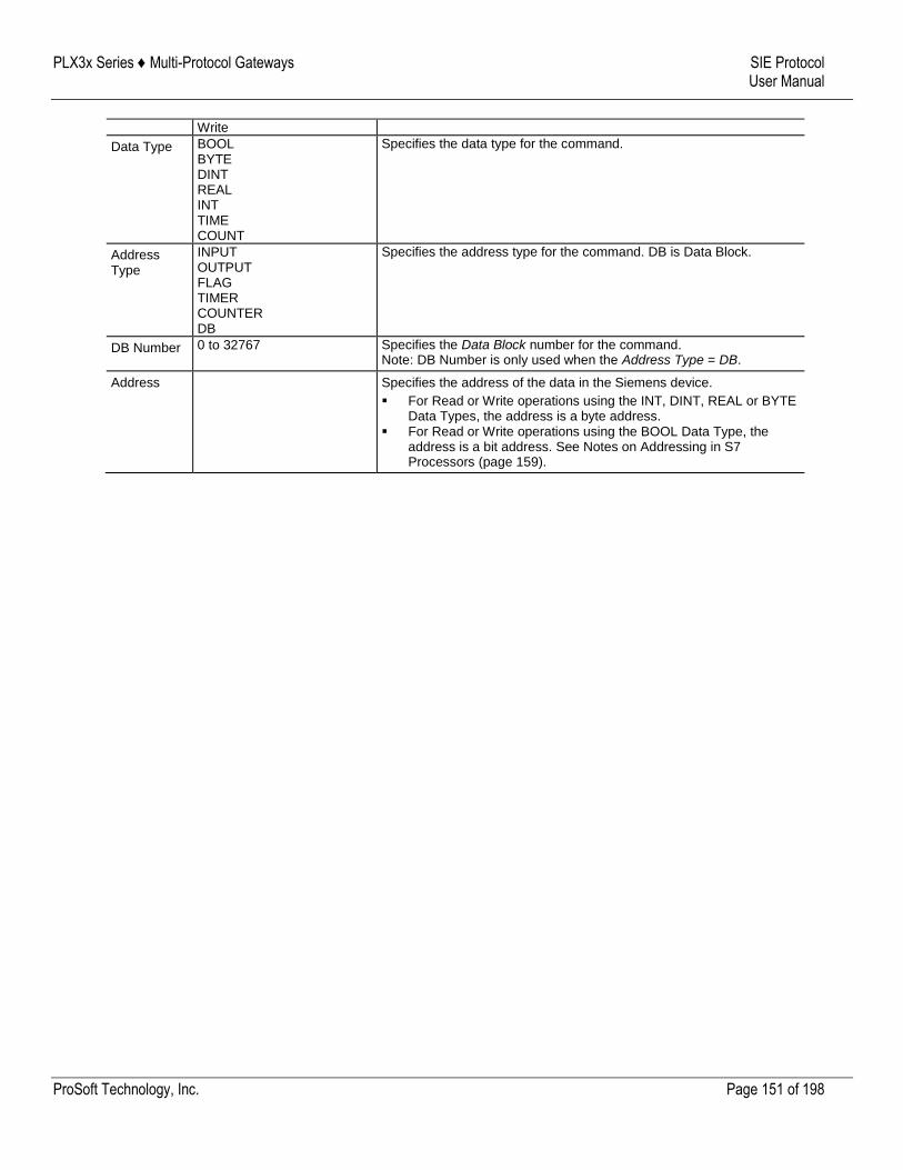
PLX3x Series ♦ Multi-Protocol Gateways SIE Protocol User Manual
ProSoft Technology, Inc. Page 151 of 198
Write
Data Type BOOL BYTE DINT REAL INT TIME COUNT
Specifies the data type for the command.
Address Type
INPUT OUTPUT FLAG TIMER COUNTER DB
Specifies the address type for the command. DB is Data Block.
DB Number 0 to 32767 Specifies the Data Block number for the command. Note: DB Number is only used when the Address Type = DB.
Address Specifies the address of the data in the Siemens device.
For Read or Write operations using the INT, DINT, REAL or BYTE Data Types, the address is a byte address.
For Read or Write operations using the BOOL Data Type, the address is a bit address. See Notes on Addressing in S7 Processors (page 159).
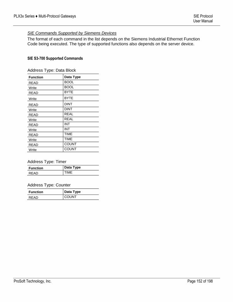
PLX3x Series ♦ Multi-Protocol Gateways SIE Protocol User Manual
ProSoft Technology, Inc. Page 152 of 198
SIE Commands Supported by Siemens Devices
The format of each command in the list depends on the Siemens Industrial Ethernet Function Code being executed. The type of supported functions also depends on the server device.
SIE S3-700 Supported Commands
Address Type: Data Block
Function Data Type
READ BOOL
Write BOOL
READ BYTE
Write BYTE
READ DINT
Write DINT
READ REAL
Write REAL
READ INT
Write INT
READ TIME
Write TIME
READ COUNT
Write COUNT
Address Type: Timer
Function Data Type
READ TIME
Address Type: Counter
Function Data Type
READ COUNT
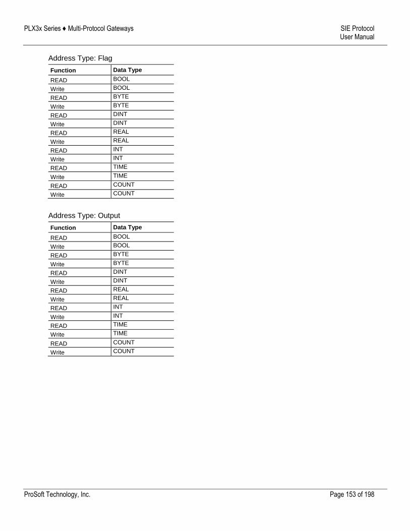
PLX3x Series ♦ Multi-Protocol Gateways SIE Protocol User Manual
ProSoft Technology, Inc. Page 153 of 198
Address Type: Flag
Function Data Type
READ BOOL
Write BOOL
READ BYTE
Write BYTE
READ DINT
Write DINT
READ REAL
Write REAL
READ INT
Write INT
READ TIME
Write TIME
READ COUNT
Write COUNT
Address Type: Output
Function Data Type
READ BOOL
Write BOOL
READ BYTE
Write BYTE
READ DINT
Write DINT
READ REAL
Write REAL
READ INT
Write INT
READ TIME
Write TIME
READ COUNT
Write COUNT
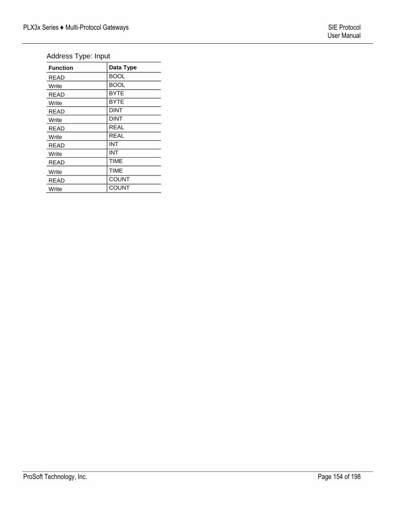
PLX3x Series ♦ Multi-Protocol Gateways SIE Protocol User Manual
ProSoft Technology, Inc. Page 154 of 198
Address Type: Input
Function Data Type
READ BOOL
Write BOOL
READ BYTE
Write BYTE
READ DINT
Write DINT
READ REAL
Write REAL
READ INT
Write INT
READ TIME
Write TIME
READ COUNT
Write COUNT
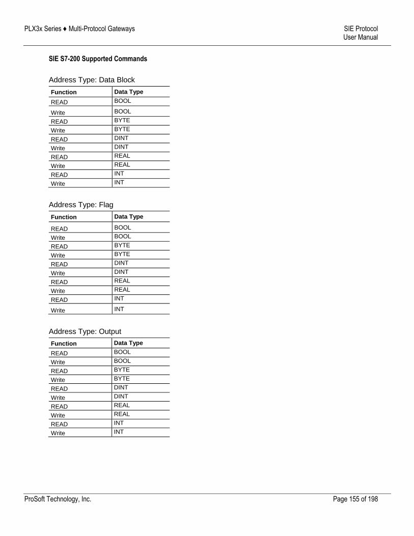
PLX3x Series ♦ Multi-Protocol Gateways SIE Protocol User Manual
ProSoft Technology, Inc. Page 155 of 198
SIE S7-200 Supported Commands
Address Type: Data Block
Function Data Type
READ BOOL
Write BOOL
READ BYTE
Write BYTE
READ DINT
Write DINT
READ REAL
Write REAL
READ INT
Write INT
Address Type: Flag
Function Data Type
READ BOOL
Write BOOL
READ BYTE
Write BYTE
READ DINT
Write DINT
READ REAL
Write REAL
READ INT
Write INT
Address Type: Output
Function Data Type
READ BOOL
Write BOOL
READ BYTE
Write BYTE
READ DINT
Write DINT
READ REAL
Write REAL
READ INT
Write INT
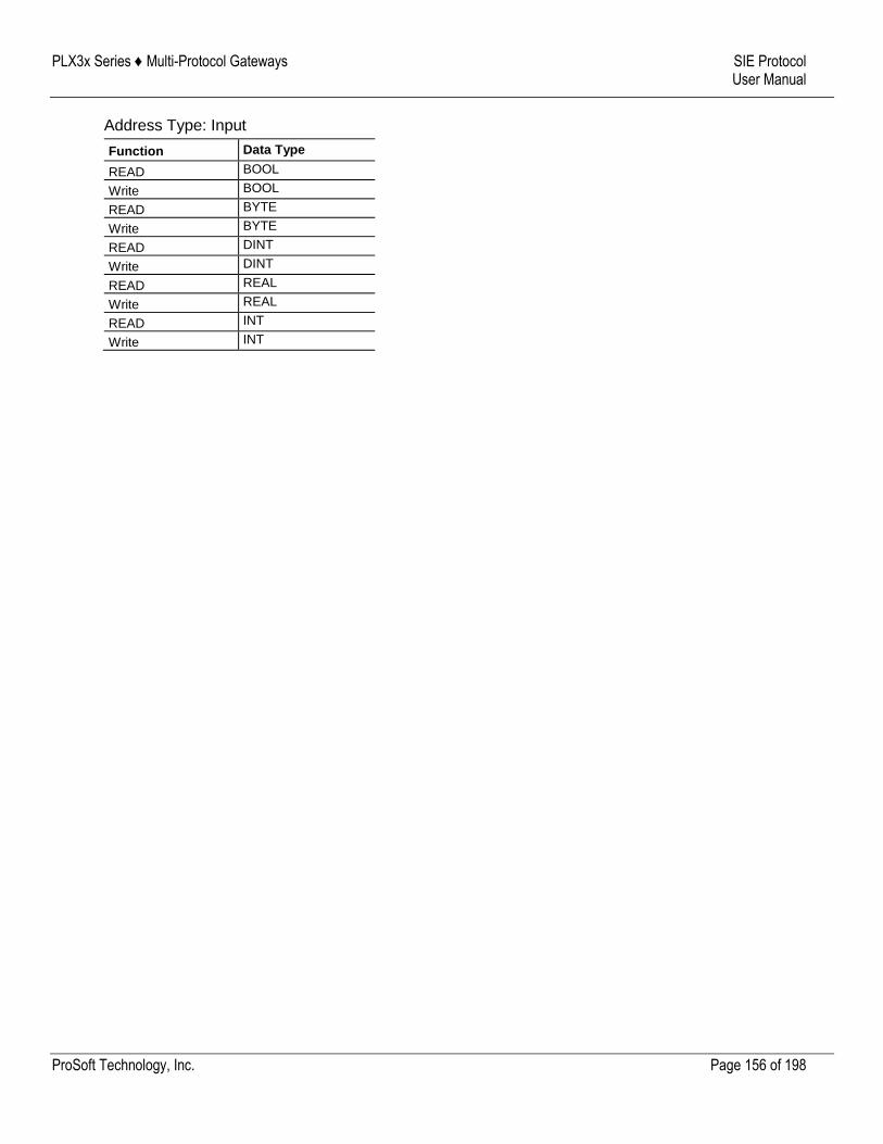
PLX3x Series ♦ Multi-Protocol Gateways SIE Protocol User Manual
ProSoft Technology, Inc. Page 156 of 198
Address Type: Input
Function Data Type
READ BOOL
Write BOOL
READ BYTE
Write BYTE
READ DINT
Write DINT
READ REAL
Write REAL
READ INT
Write INT

PLX3x Series ♦ Multi-Protocol Gateways SIE Protocol User Manual
ProSoft Technology, Inc. Page 157 of 198
SIE S7-1200 Supported Commands
Address Type: Data Block
Function Data Type
READ BOOL
Write BOOL
READ BYTE
Write BYTE
READ DINT
Write DINT
READ REAL
Write REAL
READ INT
Write INT
READ TIME
Write TIME
READ COUNT
Write COUNT
Address Type: Flag
Function Data Type
READ BOOL
Write BOOL
READ BYTE
Write BYTE
READ DINT
Write DINT
READ REAL
Write REAL
READ INT
Write INT
READ TIME
Write TIME
READ COUNT
Write COUNT
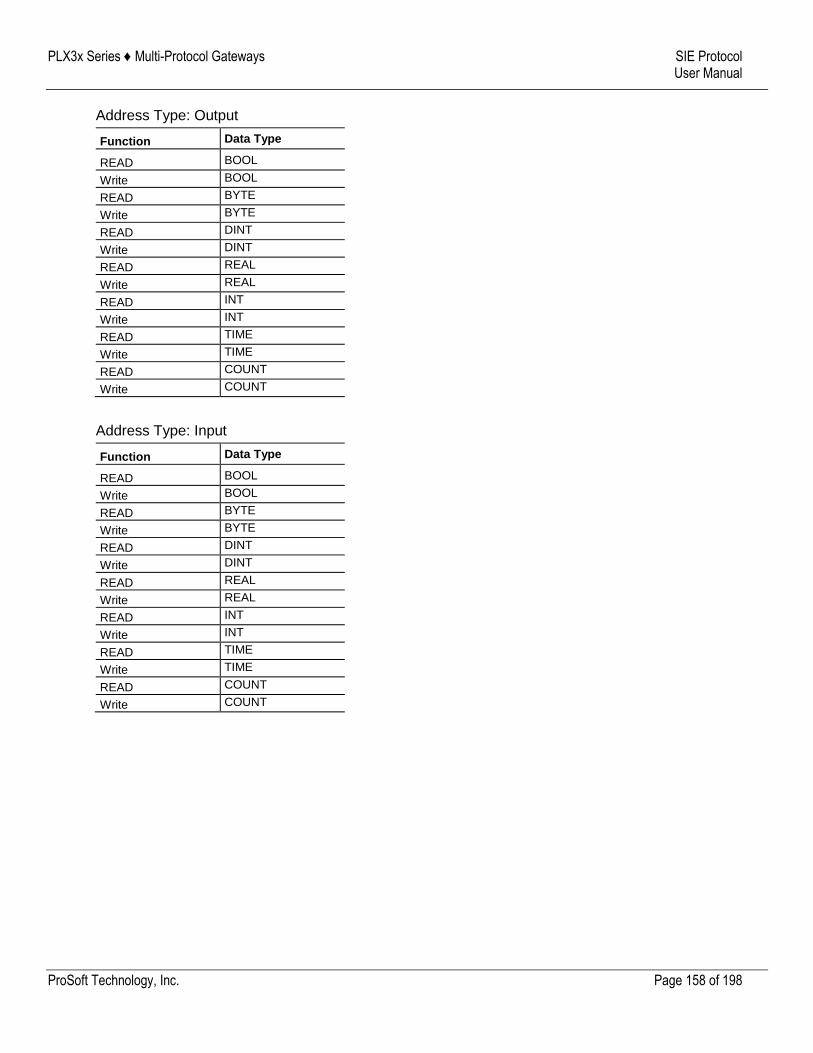
PLX3x Series ♦ Multi-Protocol Gateways SIE Protocol User Manual
ProSoft Technology, Inc. Page 158 of 198
Address Type: Output
Function Data Type
READ BOOL
Write BOOL
READ BYTE
Write BYTE
READ DINT
Write DINT
READ REAL
Write REAL
READ INT
Write INT
READ TIME
Write TIME
READ COUNT
Write COUNT
Address Type: Input
Function Data Type
READ BOOL
Write BOOL
READ BYTE
Write BYTE
READ DINT
Write DINT
READ REAL
Write REAL
READ INT
Write INT
READ TIME
Write TIME
READ COUNT
Write COUNT
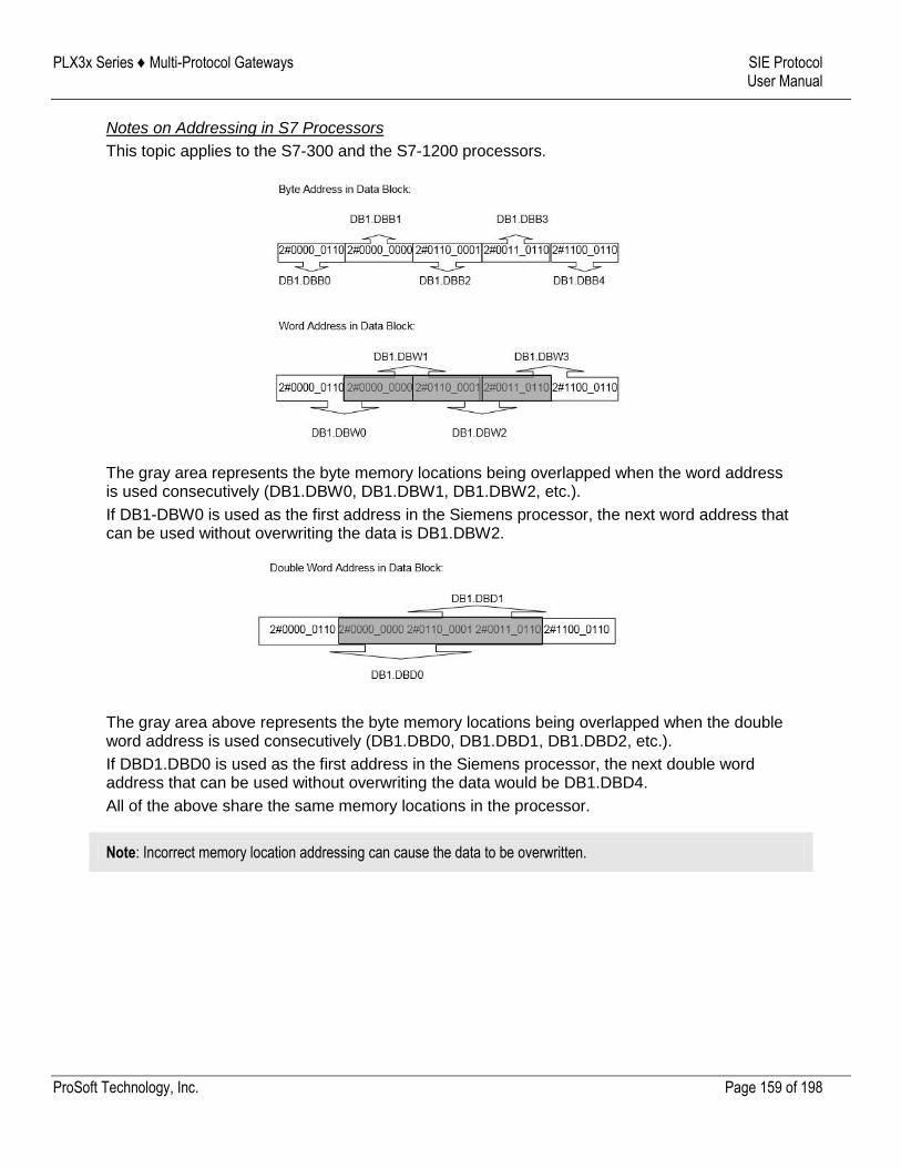
PLX3x Series ♦ Multi-Protocol Gateways SIE Protocol User Manual
ProSoft Technology, Inc. Page 159 of 198
Notes on Addressing in S7 Processors
This topic applies to the S7-300 and the S7-1200 processors.
The gray area represents the byte memory locations being overlapped when the word address is used consecutively (DB1.DBW0, DB1.DBW1, DB1.DBW2, etc.).
If DB1-DBW0 is used as the first address in the Siemens processor, the next word address that can be used without overwriting the data is DB1.DBW2.
The gray area above represents the byte memory locations being overlapped when the double word address is used consecutively (DB1.DBD0, DB1.DBD1, DB1.DBD2, etc.).
If DBD1.DBD0 is used as the first address in the Siemens processor, the next double word address that can be used without overwriting the data would be DB1.DBD4.
All of the above share the same memory locations in the processor.
Note: Incorrect memory location addressing can cause the data to be overwritten.
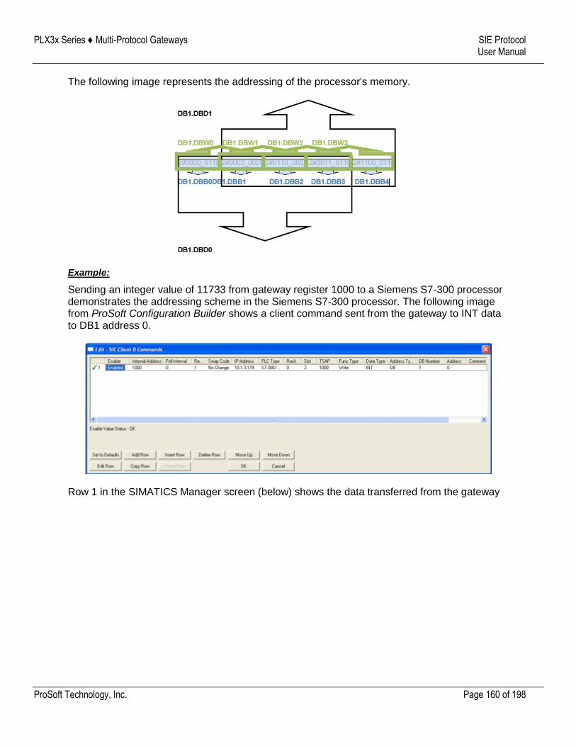
PLX3x Series ♦ Multi-Protocol Gateways SIE Protocol User Manual
ProSoft Technology, Inc. Page 160 of 198
The following image represents the addressing of the processor's memory.
Example:
Sending an integer value of 11733 from gateway register 1000 to a Siemens S7-300 processor demonstrates the addressing scheme in the Siemens S7-300 processor. The following image from ProSoft Configuration Builder shows a client command sent from the gateway to INT data to DB1 address 0.
Row 1 in the SIMATICS Manager screen (below) shows the data transferred from the gateway
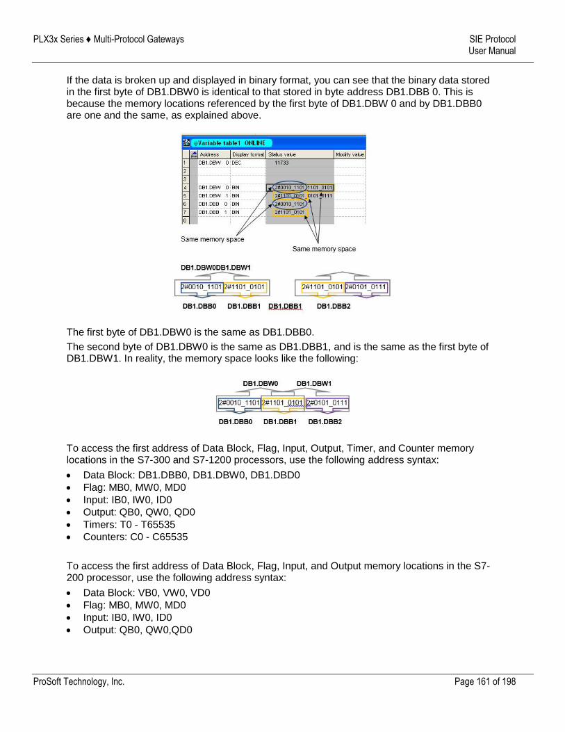
PLX3x Series ♦ Multi-Protocol Gateways SIE Protocol User Manual
ProSoft Technology, Inc. Page 161 of 198
If the data is broken up and displayed in binary format, you can see that the binary data stored in the first byte of DB1.DBW0 is identical to that stored in byte address DB1.DBB 0. This is because the memory locations referenced by the first byte of DB1.DBW 0 and by DB1.DBB0 are one and the same, as explained above.
The first byte of DB1.DBW0 is the same as DB1.DBB0.
The second byte of DB1.DBW0 is the same as DB1.DBB1, and is the same as the first byte of DB1.DBW1. In reality, the memory space looks like the following:
To access the first address of Data Block, Flag, Input, Output, Timer, and Counter memory locations in the S7-300 and S7-1200 processors, use the following address syntax:
Data Block: DB1.DBB0, DB1.DBW0, DB1.DBD0
Flag: MB0, MW0, MD0
Input: IB0, IW0, ID0
Output: QB0, QW0, QD0
Timers: T0 - T65535
Counters: C0 - C65535
To access the first address of Data Block, Flag, Input, and Output memory locations in the S7-200 processor, use the following address syntax:
Data Block: VB0, VW0, VD0
Flag: MB0, MW0, MD0
Input: IB0, IW0, ID0
Output: QB0, QW0,QD0
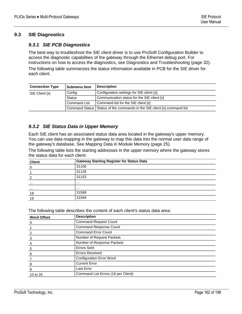
PLX3x Series ♦ Multi-Protocol Gateways SIE Protocol User Manual
ProSoft Technology, Inc. Page 162 of 198
9.3 SIE Diagnostics
9.3.1 SIE PCB Diagnostics
The best way to troubleshoot the SIE client driver is to use ProSoft Configuration Builder to access the diagnostic capabilities of the gateway through the Ethernet debug port. For instructions on how to access the diagnostics, see Diagnostics and Troubleshooting (page 32).
The following table summarizes the status information available in PCB for the SIE driver for each client.
Connection Type Submenu Item Description
SIE Client [x] Config Configuration settings for SIE client [x].
Status Communication status for the SIE client [x]
Command List Command list for the SIE client [x]
Command Status Status of the commands in the SIE client [x] command list
9.3.2 SIE Status Data in Upper Memory
Each SIE client has an associated status data area located in the gateway's upper memory. You can use data mapping in the gateway to map this data into the normal user data range of the gateway's database. See Mapping Data in Module Memory (page 25).
The following table lists the starting addresses in the upper memory where the gateway stores the status data for each client:
Client Gateway Starting Register for Status Data
0 31100
1 31126
2 31152
… …
… …
18 31568
19 31594
The following table describes the content of each client's status data area:
Word Offset Description
0 Command Request Count
1 Command Response Count
2 Command Error Count
3 Number of Request Packets
4 Number of Response Packets
5 Errors Sent
6 Errors Received
7 Configuration Error Word
8 Current Error
9 Last Error
10 to 25 Command List Errors (16 per Client)
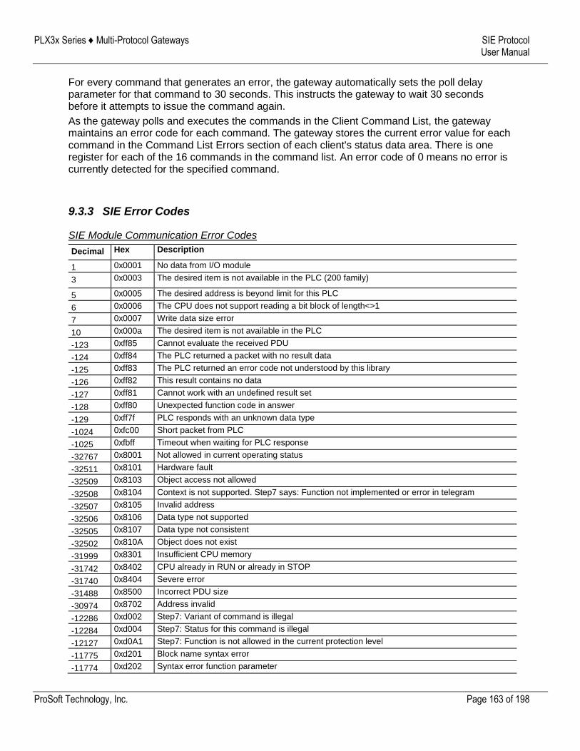
PLX3x Series ♦ Multi-Protocol Gateways SIE Protocol User Manual
ProSoft Technology, Inc. Page 163 of 198
For every command that generates an error, the gateway automatically sets the poll delay parameter for that command to 30 seconds. This instructs the gateway to wait 30 seconds before it attempts to issue the command again.
As the gateway polls and executes the commands in the Client Command List, the gateway maintains an error code for each command. The gateway stores the current error value for each command in the Command List Errors section of each client's status data area. There is one register for each of the 16 commands in the command list. An error code of 0 means no error is currently detected for the specified command.
9.3.3 SIE Error Codes
SIE Module Communication Error Codes
Decimal Hex Description
1 0x0001 No data from I/O module
3 0x0003 The desired item is not available in the PLC (200 family)
5 0x0005 The desired address is beyond limit for this PLC
6 0x0006 The CPU does not support reading a bit block of length<>1
7 0x0007 Write data size error
10 0x000a The desired item is not available in the PLC
-123 0xff85 Cannot evaluate the received PDU
-124 0xff84 The PLC returned a packet with no result data
-125 0xff83 The PLC returned an error code not understood by this library
-126 0xff82 This result contains no data
-127 0xff81 Cannot work with an undefined result set
-128 0xff80 Unexpected function code in answer
-129 0xff7f PLC responds with an unknown data type
-1024 0xfc00 Short packet from PLC
-1025 0xfbff Timeout when waiting for PLC response
-32767 0x8001 Not allowed in current operating status
-32511 0x8101 Hardware fault
-32509 0x8103 Object access not allowed
-32508 0x8104 Context is not supported. Step7 says: Function not implemented or error in telegram
-32507 0x8105 Invalid address
-32506 0x8106 Data type not supported
-32505 0x8107 Data type not consistent
-32502 0x810A Object does not exist
-31999 0x8301 Insufficient CPU memory
-31742 0x8402 CPU already in RUN or already in STOP
-31740 0x8404 Severe error
-31488 0x8500 Incorrect PDU size
-30974 0x8702 Address invalid
-12286 0xd002 Step7: Variant of command is illegal
-12284 0xd004 Step7: Status for this command is illegal
-12127 0xd0A1 Step7: Function is not allowed in the current protection level
-11775 0xd201 Block name syntax error
-11774 0xd202 Syntax error function parameter
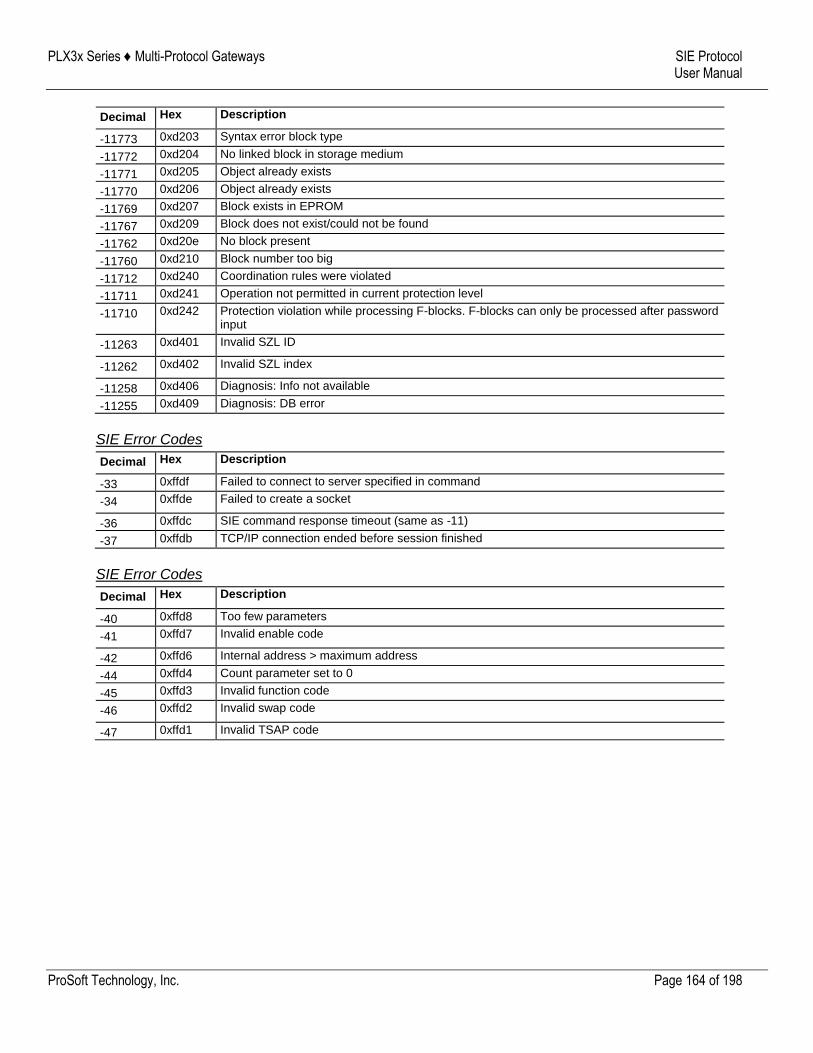
PLX3x Series ♦ Multi-Protocol Gateways SIE Protocol User Manual
ProSoft Technology, Inc. Page 164 of 198
Decimal Hex Description
-11773 0xd203 Syntax error block type
-11772 0xd204 No linked block in storage medium
-11771 0xd205 Object already exists
-11770 0xd206 Object already exists
-11769 0xd207 Block exists in EPROM
-11767 0xd209 Block does not exist/could not be found
-11762 0xd20e No block present
-11760 0xd210 Block number too big
-11712 0xd240 Coordination rules were violated
-11711 0xd241 Operation not permitted in current protection level
-11710 0xd242 Protection violation while processing F-blocks. F-blocks can only be processed after password input
-11263 0xd401 Invalid SZL ID
-11262 0xd402 Invalid SZL index
-11258 0xd406 Diagnosis: Info not available
-11255 0xd409 Diagnosis: DB error
SIE Error Codes
Decimal Hex Description
-33 0xffdf Failed to connect to server specified in command
-34 0xffde Failed to create a socket
-36 0xffdc SIE command response timeout (same as -11)
-37 0xffdb TCP/IP connection ended before session finished
SIE Error Codes
Decimal Hex Description
-40 0xffd8 Too few parameters
-41 0xffd7 Invalid enable code
-42 0xffd6 Internal address > maximum address
-44 0xffd4 Count parameter set to 0
-45 0xffd3 Invalid function code
-46 0xffd2 Invalid swap code
-47 0xffd1 Invalid TSAP code
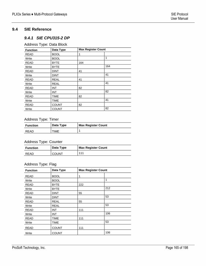
PLX3x Series ♦ Multi-Protocol Gateways SIE Protocol User Manual
ProSoft Technology, Inc. Page 165 of 198
9.4 SIE Reference
9.4.1 SIE CPU315-2 DP
Address Type: Data Block
Function Data Type Max Register Count
READ BOOL 1
Write BOOL 1
READ BYTE 164
Write BYTE 164
READ DINT 41
Write DINT 41
READ REAL 41
Write REAL 41
READ INT 82
Write INT 82
READ TIME 82
Write TIME 41
READ COUNT 82
Write COUNT 82
Address Type: Timer
Function Data Type Max Register Count
READ TIME 1
Address Type: Counter
Function Data Type Max Register Count
READ COUNT 111
Address Type: Flag
Function Data Type Max Register Count
READ BOOL 1
Write BOOL 1
READ BYTE 222
Write BYTE 212
READ DINT 55
Write DINT 53
READ REAL 55
Write REAL 53
READ INT 111
Write INT 106
READ TIME 111
Write TIME 53
READ COUNT 111
Write COUNT 106
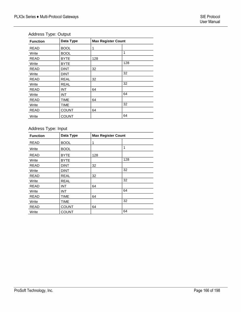
PLX3x Series ♦ Multi-Protocol Gateways SIE Protocol User Manual
ProSoft Technology, Inc. Page 166 of 198
Address Type: Output
Function Data Type Max Register Count
READ BOOL 1
Write BOOL 1
READ BYTE 128
Write BYTE 128
READ DINT 32
Write DINT 32
READ REAL 32
Write REAL 32
READ INT 64
Write INT 64
READ TIME 64
Write TIME 32
READ COUNT 64
Write COUNT 64
Address Type: Input
Function Data Type Max Register Count
READ BOOL 1
Write BOOL 1
READ BYTE 128
Write BYTE 128
READ DINT 32
Write DINT 32
READ REAL 32
Write REAL 32
READ INT 64
Write INT 64
READ TIME 64
Write TIME 32
READ COUNT 64
Write COUNT 64
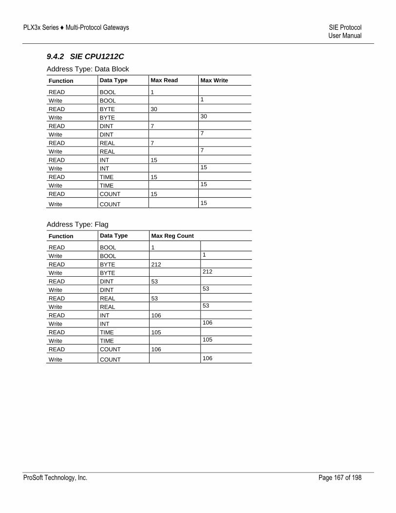
PLX3x Series ♦ Multi-Protocol Gateways SIE Protocol User Manual
ProSoft Technology, Inc. Page 167 of 198
9.4.2 SIE CPU1212C
Address Type: Data Block
Function Data Type Max Read Max Write
READ BOOL 1
Write BOOL 1
READ BYTE 30
Write BYTE 30
READ DINT 7
Write DINT 7
READ REAL 7
Write REAL 7
READ INT 15
Write INT 15
READ TIME 15
Write TIME 15
READ COUNT 15
Write COUNT 15
Address Type: Flag
Function Data Type Max Reg Count
READ BOOL 1
Write BOOL 1
READ BYTE 212
Write BYTE 212
READ DINT 53
Write DINT 53
READ REAL 53
Write REAL 53
READ INT 106
Write INT 106
READ TIME 105
Write TIME 105
READ COUNT 106
Write COUNT 106
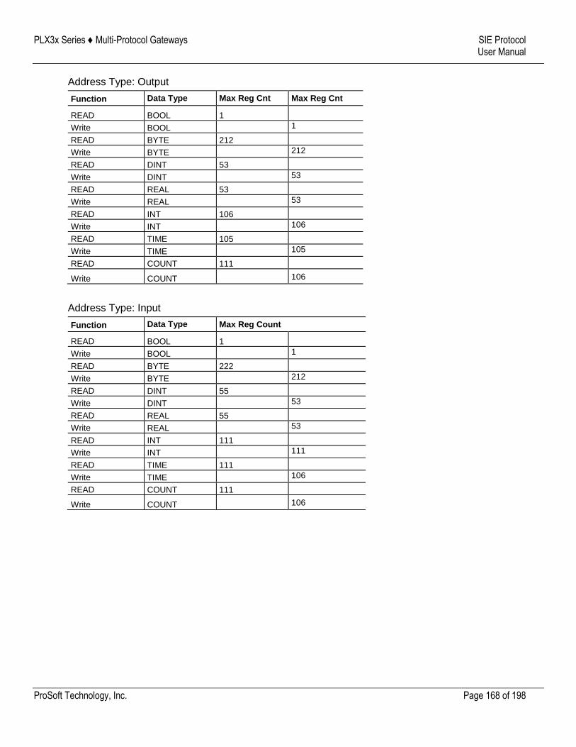
PLX3x Series ♦ Multi-Protocol Gateways SIE Protocol User Manual
ProSoft Technology, Inc. Page 168 of 198
Address Type: Output
Function Data Type Max Reg Cnt Max Reg Cnt
READ BOOL 1
Write BOOL 1
READ BYTE 212
Write BYTE 212
READ DINT 53
Write DINT 53
READ REAL 53
Write REAL 53
READ INT 106
Write INT 106
READ TIME 105
Write TIME 105
READ COUNT 111
Write COUNT 106
Address Type: Input
Function Data Type Max Reg Count
READ BOOL 1
Write BOOL 1
READ BYTE 222
Write BYTE 212
READ DINT 55
Write DINT 53
READ REAL 55
Write REAL 53
READ INT 111
Write INT 111
READ TIME 111
Write TIME 106
READ COUNT 111
Write COUNT 106
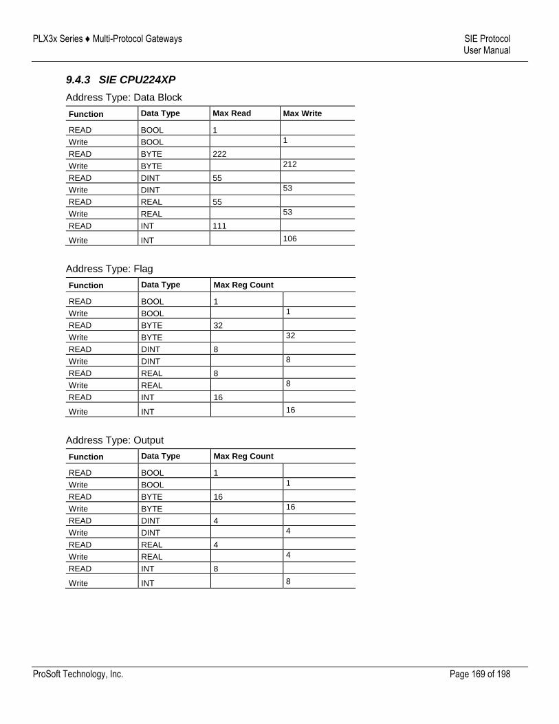
PLX3x Series ♦ Multi-Protocol Gateways SIE Protocol User Manual
ProSoft Technology, Inc. Page 169 of 198
9.4.3 SIE CPU224XP
Address Type: Data Block
Function Data Type Max Read Max Write
READ BOOL 1
Write BOOL 1
READ BYTE 222
Write BYTE 212
READ DINT 55
Write DINT 53
READ REAL 55
Write REAL 53
READ INT 111
Write INT 106
Address Type: Flag
Function Data Type Max Reg Count
READ BOOL 1
Write BOOL 1
READ BYTE 32
Write BYTE 32
READ DINT 8
Write DINT 8
READ REAL 8
Write REAL 8
READ INT 16
Write INT 16
Address Type: Output
Function Data Type Max Reg Count
READ BOOL 1
Write BOOL 1
READ BYTE 16
Write BYTE 16
READ DINT 4
Write DINT 4
READ REAL 4
Write REAL 4
READ INT 8
Write INT 8
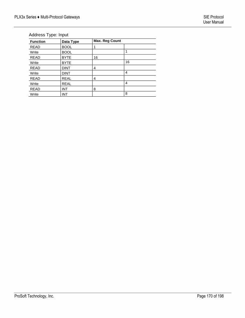
PLX3x Series ♦ Multi-Protocol Gateways SIE Protocol User Manual
ProSoft Technology, Inc. Page 170 of 198
Address Type: Input
Function Data Type Max. Reg Count
READ BOOL 1
Write BOOL 1
READ BYTE 16
Write BYTE 16
READ DINT 4
Write DINT 4
READ REAL 4
Write REAL 4
READ INT 8
Write INT 8
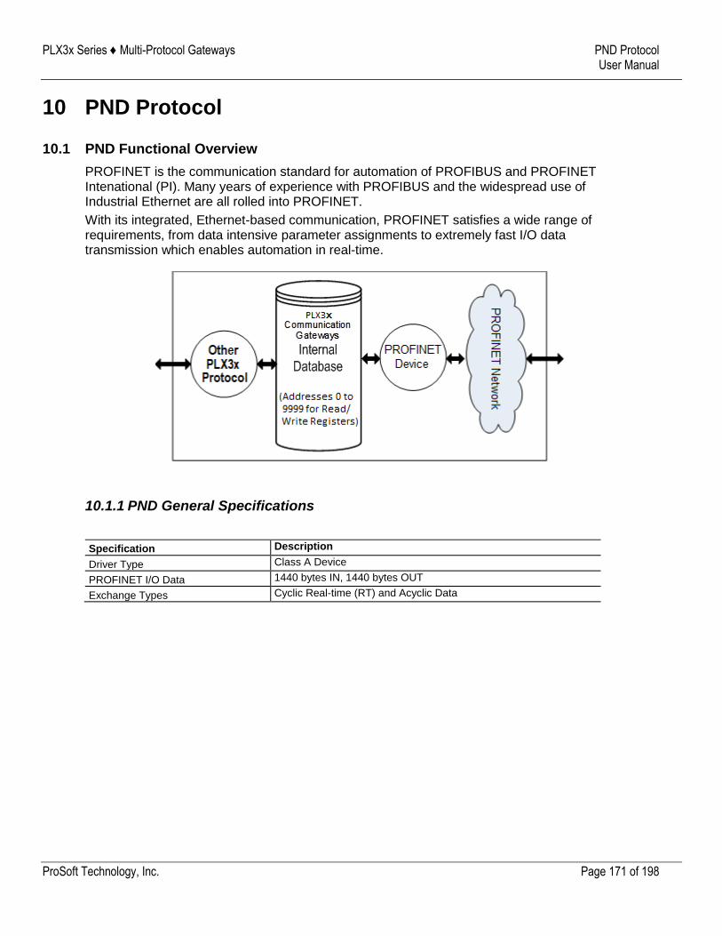
PLX3x Series ♦ Multi-Protocol Gateways PND Protocol User Manual
ProSoft Technology, Inc. Page 171 of 198
10 PND Protocol
10.1 PND Functional Overview
PROFINET is the communication standard for automation of PROFIBUS and PROFINET Intenational (PI). Many years of experience with PROFIBUS and the widespread use of Industrial Ethernet are all rolled into PROFINET.
With its integrated, Ethernet-based communication, PROFINET satisfies a wide range of requirements, from data intensive parameter assignments to extremely fast I/O data transmission which enables automation in real-time.
10.1.1 PND General Specifications
Specification Description
Driver Type Class A Device
PROFINET I/O Data 1440 bytes IN, 1440 bytes OUT
Exchange Types Cyclic Real-time (RT) and Acyclic Data
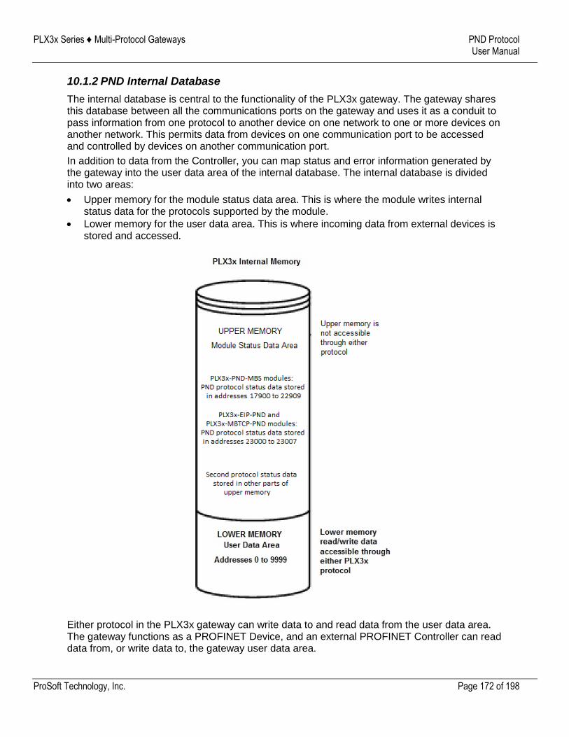
PLX3x Series ♦ Multi-Protocol Gateways PND Protocol User Manual
ProSoft Technology, Inc. Page 172 of 198
10.1.2 PND Internal Database
The internal database is central to the functionality of the PLX3x gateway. The gateway shares this database between all the communications ports on the gateway and uses it as a conduit to pass information from one protocol to another device on one network to one or more devices on another network. This permits data from devices on one communication port to be accessed and controlled by devices on another communication port.
In addition to data from the Controller, you can map status and error information generated by the gateway into the user data area of the internal database. The internal database is divided into two areas:
Upper memory for the module status data area. This is where the module writes internal status data for the protocols supported by the module.
Lower memory for the user data area. This is where incoming data from external devices is stored and accessed.
Either protocol in the PLX3x gateway can write data to and read data from the user data area. The gateway functions as a PROFINET Device, and an external PROFINET Controller can read data from, or write data to, the gateway user data area.
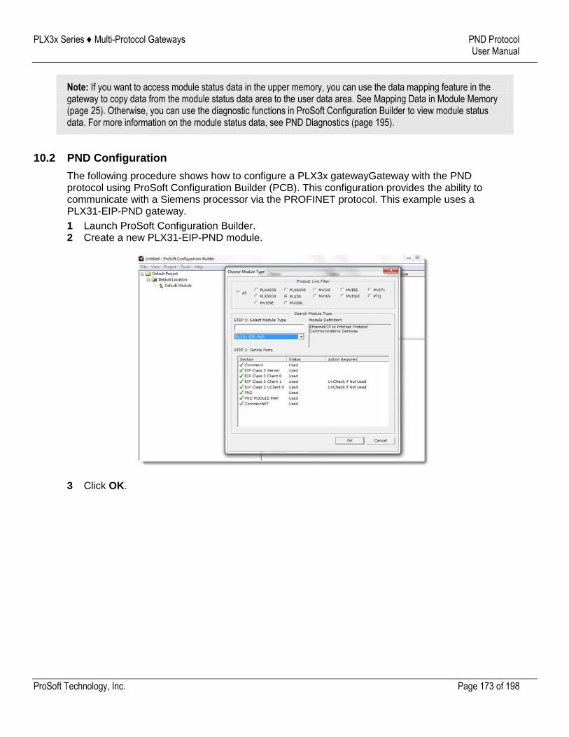
PLX3x Series ♦ Multi-Protocol Gateways PND Protocol User Manual
ProSoft Technology, Inc. Page 173 of 198
Note: If you want to access module status data in the upper memory, you can use the data mapping feature in the gateway to copy data from the module status data area to the user data area. See Mapping Data in Module Memory (page 25). Otherwise, you can use the diagnostic functions in ProSoft Configuration Builder to view module status data. For more information on the module status data, see PND Diagnostics (page 195).
10.2 PND Configuration
The following procedure shows how to configure a PLX3x gatewayGateway with the PND protocol using ProSoft Configuration Builder (PCB). This configuration provides the ability to communicate with a Siemens processor via the PROFINET protocol. This example uses a PLX31-EIP-PND gateway.
1 Launch ProSoft Configuration Builder. 2 Create a new PLX31-EIP-PND module.
3 Click OK.
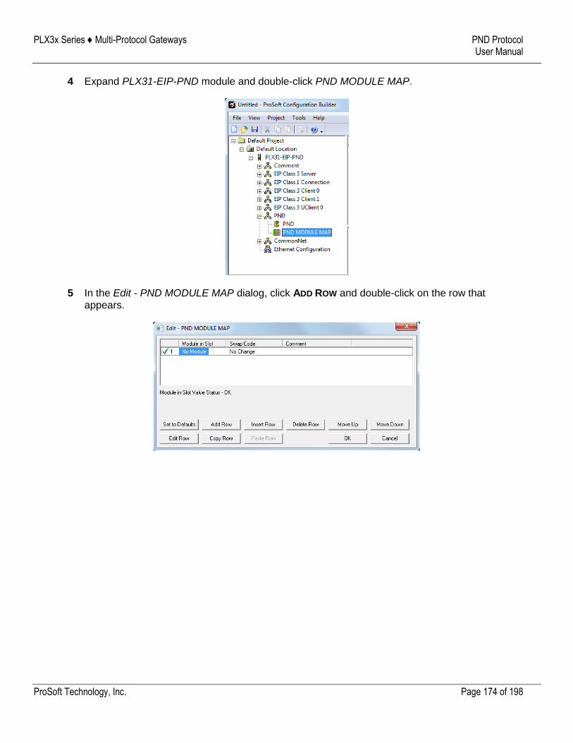
PLX3x Series ♦ Multi-Protocol Gateways PND Protocol User Manual
ProSoft Technology, Inc. Page 174 of 198
4 Expand PLX31-EIP-PND module and double-click PND MODULE MAP.
5 In the Edit - PND MODULE MAP dialog, click ADD ROW and double-click on the row that appears.
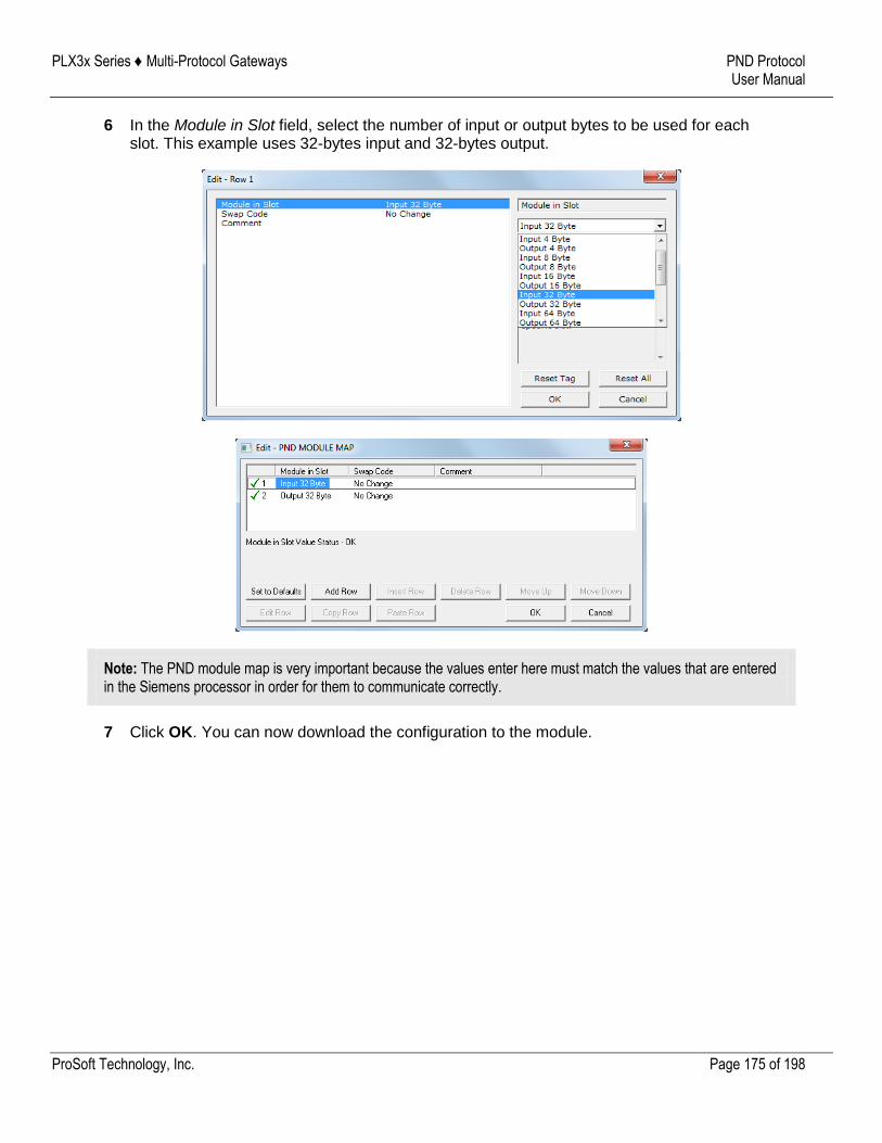
PLX3x Series ♦ Multi-Protocol Gateways PND Protocol User Manual
ProSoft Technology, Inc. Page 175 of 198
6 In the Module in Slot field, select the number of input or output bytes to be used for each slot. This example uses 32-bytes input and 32-bytes output.
Note: The PND module map is very important because the values enter here must match the values that are entered in the Siemens processor in order for them to communicate correctly.
7 Click OK. You can now download the configuration to the module.
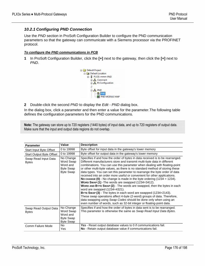
PLX3x Series ♦ Multi-Protocol Gateways PND Protocol User Manual
ProSoft Technology, Inc. Page 176 of 198
10.2.1 Configuring PND Connection
Use the PND section in ProSoft Configuration Builder to configure the PND communication parameters so that the gateway can communicate with a Siemens processor via the PROFINET protocol.
To configure the PND communications in PCB
1 In ProSoft Configuration Builder, click the [+] next to the gateway, then click the [+] next to PND.
2 Double-click the second PND to display the Edit - PND dialog box.
In the dialog box, click a parameter and then enter a value for the parameter.The following table defines the configuration parameters for the PND communications.
Note: The gateway can store up to 720 registers (1440 bytes) of input data, and up to 720 registers of output data. Make sure that the input and output data regions do not overlap.
Parameter Value Description
Start Input Byte Offset 0 to 19998 Byte offset for input data in the gateway's lower memory
Start Output Byte Offset 0 to 19998 Byte offset for output data in the gateway's lower memory
Swap Read Input Data Bytes
No Change Word Swap Word and Byte Swap Byte Swap
Specifies if and how the order of bytes in data received is to be rearranged. Different manufacturers store and transmit multi-byte data in different combinations. You can use this parameter when dealing with floating-point or other multi-byte values, as there is no standard method of storing these data types. You can set this parameter to rearrange the byte order of data received into an order more useful or convenient for other applications. NO CHANGE (0) - No change is made in the byte ordering (1234 = 1234). WORD SWAP (1) -The words are swapped (1234=3412). WORD AND BYTE SWAP (2) - The words are swapped, then the bytes in each
word are swapped (1234=4321). BYTE SWAP (3) - The bytes in each word are swapped (1234=2143).
These swap operations affect 4-byte (2-word) groups of data. Therefore, data swapping using Swap Codes should be done only when using an even number of words, such as 32-bit integer or floating-point data.
Swap Read Output Data Bytes
No Change Word Swap Word and Byte Swap Byte Swap
Specifies if and how the order of bytes in data sent is to be rearranged. This parameter is otherwise the same as Swap Read Input Data Bytes.
Comm Failure Mode No Yes
YES - Reset output database values to 0 if communications fail. NO - Retain output database value if communications fail.
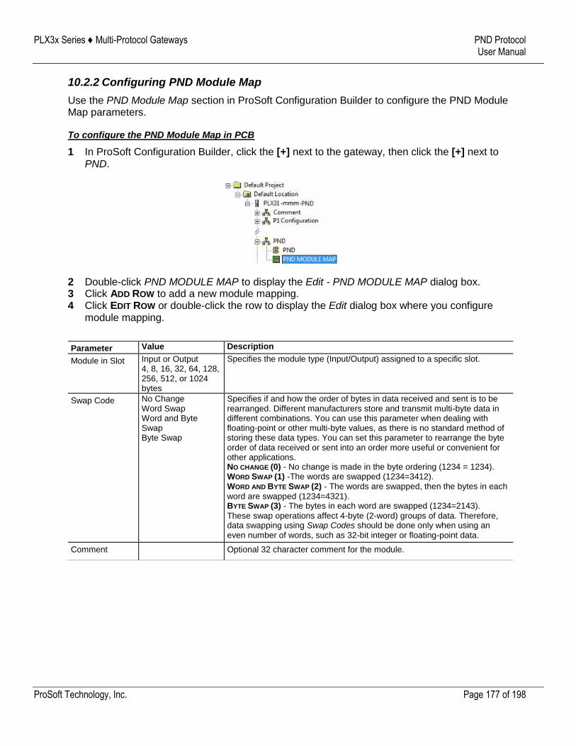
PLX3x Series ♦ Multi-Protocol Gateways PND Protocol User Manual
ProSoft Technology, Inc. Page 177 of 198
10.2.2 Configuring PND Module Map
Use the PND Module Map section in ProSoft Configuration Builder to configure the PND Module Map parameters.
To configure the PND Module Map in PCB
1 In ProSoft Configuration Builder, click the [+] next to the gateway, then click the [+] next to PND.
2 Double-click PND MODULE MAP to display the Edit - PND MODULE MAP dialog box. 3 Click ADD ROW to add a new module mapping. 4 Click EDIT ROW or double-click the row to display the Edit dialog box where you configure
module mapping.
Parameter Value Description
Module in Slot Input or Output 4, 8, 16, 32, 64, 128, 256, 512, or 1024 bytes
Specifies the module type (Input/Output) assigned to a specific slot.
Swap Code No Change Word Swap Word and Byte Swap Byte Swap
Specifies if and how the order of bytes in data received and sent is to be rearranged. Different manufacturers store and transmit multi-byte data in different combinations. You can use this parameter when dealing with floating-point or other multi-byte values, as there is no standard method of storing these data types. You can set this parameter to rearrange the byte order of data received or sent into an order more useful or convenient for other applications. NO CHANGE (0) - No change is made in the byte ordering (1234 = 1234). WORD SWAP (1) -The words are swapped (1234=3412). WORD AND BYTE SWAP (2) - The words are swapped, then the bytes in each
word are swapped (1234=4321). BYTE SWAP (3) - The bytes in each word are swapped (1234=2143).
These swap operations affect 4-byte (2-word) groups of data. Therefore, data swapping using Swap Codes should be done only when using an even number of words, such as 32-bit integer or floating-point data.
Comment Optional 32 character comment for the module.
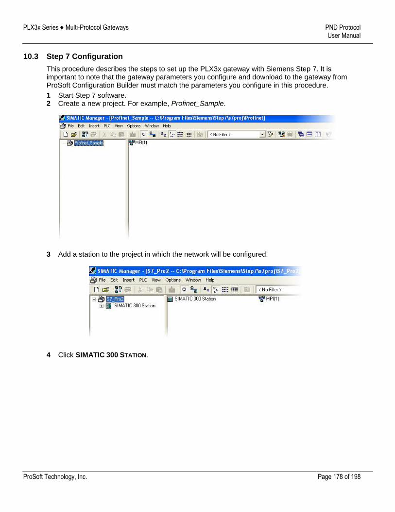
PLX3x Series ♦ Multi-Protocol Gateways PND Protocol User Manual
ProSoft Technology, Inc. Page 178 of 198
10.3 Step 7 Configuration
This procedure describes the steps to set up the PLX3x gateway with Siemens Step 7. It is important to note that the gateway parameters you configure and download to the gateway from ProSoft Configuration Builder must match the parameters you configure in this procedure.
1 Start Step 7 software. 2 Create a new project. For example, Profinet_Sample.
3 Add a station to the project in which the network will be configured.
4 Click SIMATIC 300 STATION.
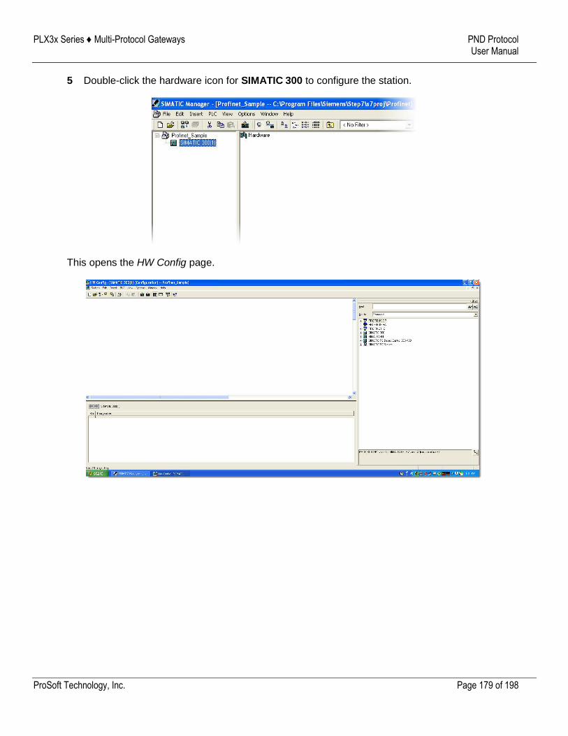
PLX3x Series ♦ Multi-Protocol Gateways PND Protocol User Manual
ProSoft Technology, Inc. Page 179 of 198
5 Double-click the hardware icon for SIMATIC 300 to configure the station.
This opens the HW Config page.
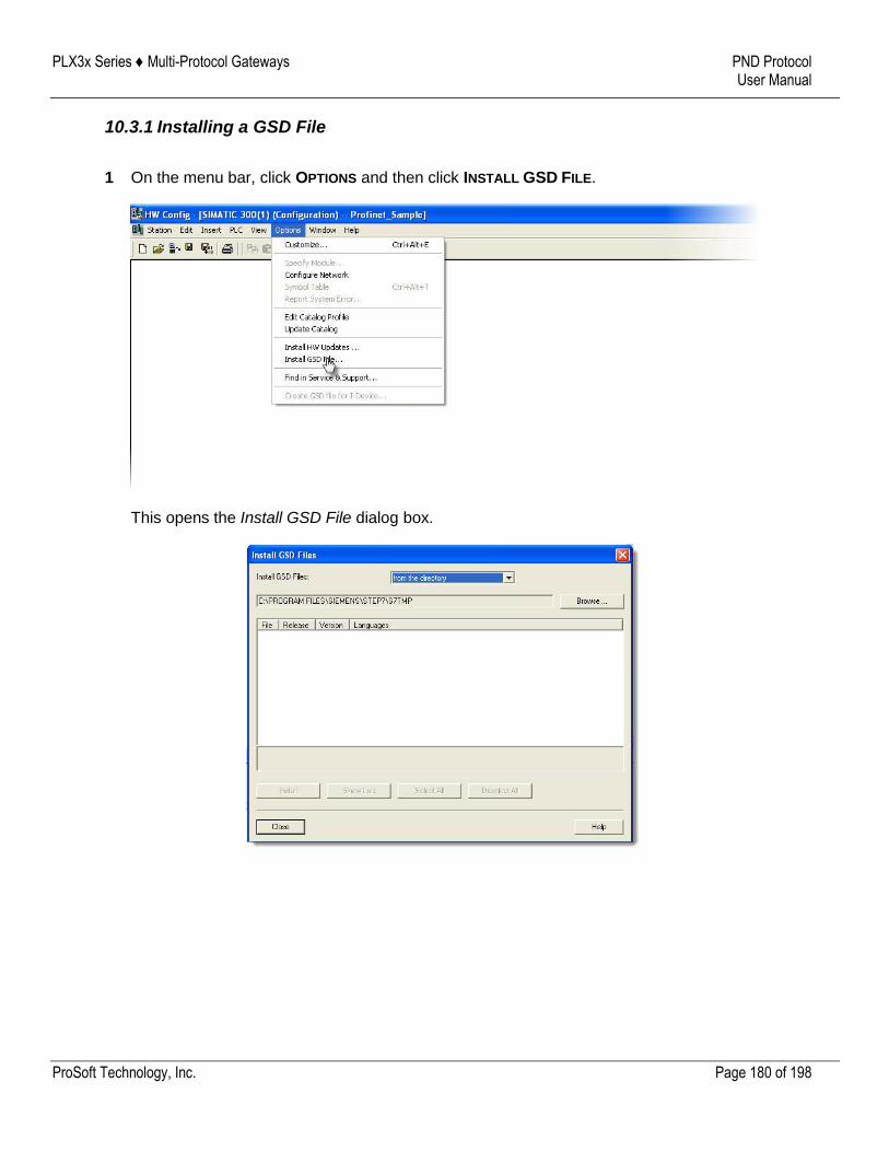
PLX3x Series ♦ Multi-Protocol Gateways PND Protocol User Manual
ProSoft Technology, Inc. Page 180 of 198
10.3.1 Installing a GSD File
1 On the menu bar, click OPTIONS and then click INSTALL GSD FILE.
This opens the Install GSD File dialog box.
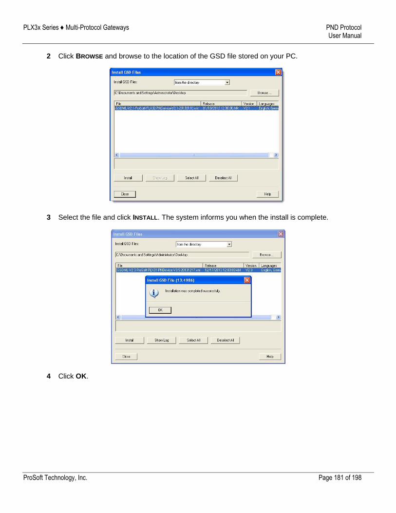
PLX3x Series ♦ Multi-Protocol Gateways PND Protocol User Manual
ProSoft Technology, Inc. Page 181 of 198
2 Click BROWSE and browse to the location of the GSD file stored on your PC.
3 Select the file and click INSTALL. The system informs you when the install is complete.
4 Click OK.
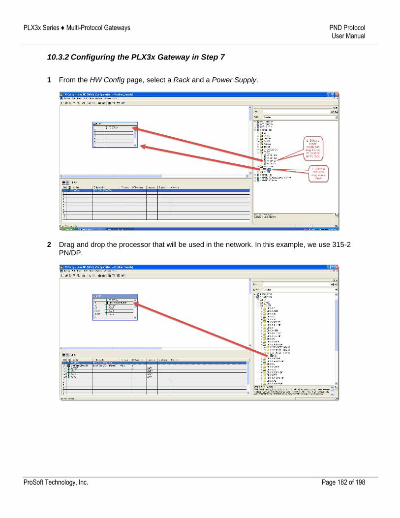
PLX3x Series ♦ Multi-Protocol Gateways PND Protocol User Manual
ProSoft Technology, Inc. Page 182 of 198
10.3.2 Configuring the PLX3x Gateway in Step 7
1 From the HW Config page, select a Rack and a Power Supply.
2 Drag and drop the processor that will be used in the network. In this example, we use 315-2 PN/DP.
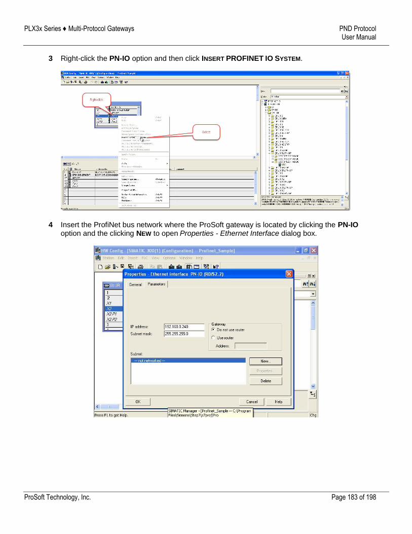
PLX3x Series ♦ Multi-Protocol Gateways PND Protocol User Manual
ProSoft Technology, Inc. Page 183 of 198
3 Right-click the PN-IO option and then click INSERT PROFINET IO SYSTEM.
4 Insert the ProfiNet bus network where the ProSoft gateway is located by clicking the PN-IO option and the clicking NEW to open Properties - Ethernet Interface dialog box.
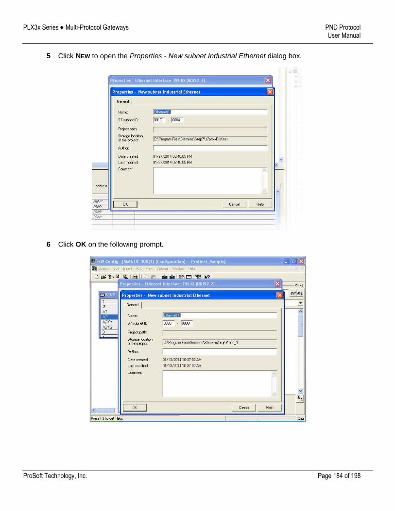
PLX3x Series ♦ Multi-Protocol Gateways PND Protocol User Manual
ProSoft Technology, Inc. Page 184 of 198
5 Click NEW to open the Properties - New subnet Industrial Ethernet dialog box.
6 Click OK on the following prompt.
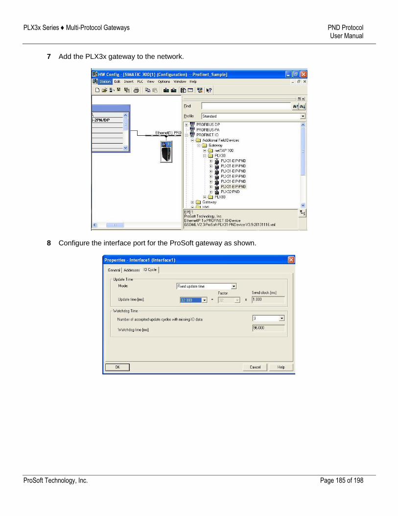
PLX3x Series ♦ Multi-Protocol Gateways PND Protocol User Manual
ProSoft Technology, Inc. Page 185 of 198
7 Add the PLX3x gateway to the network.
8 Configure the interface port for the ProSoft gateway as shown.
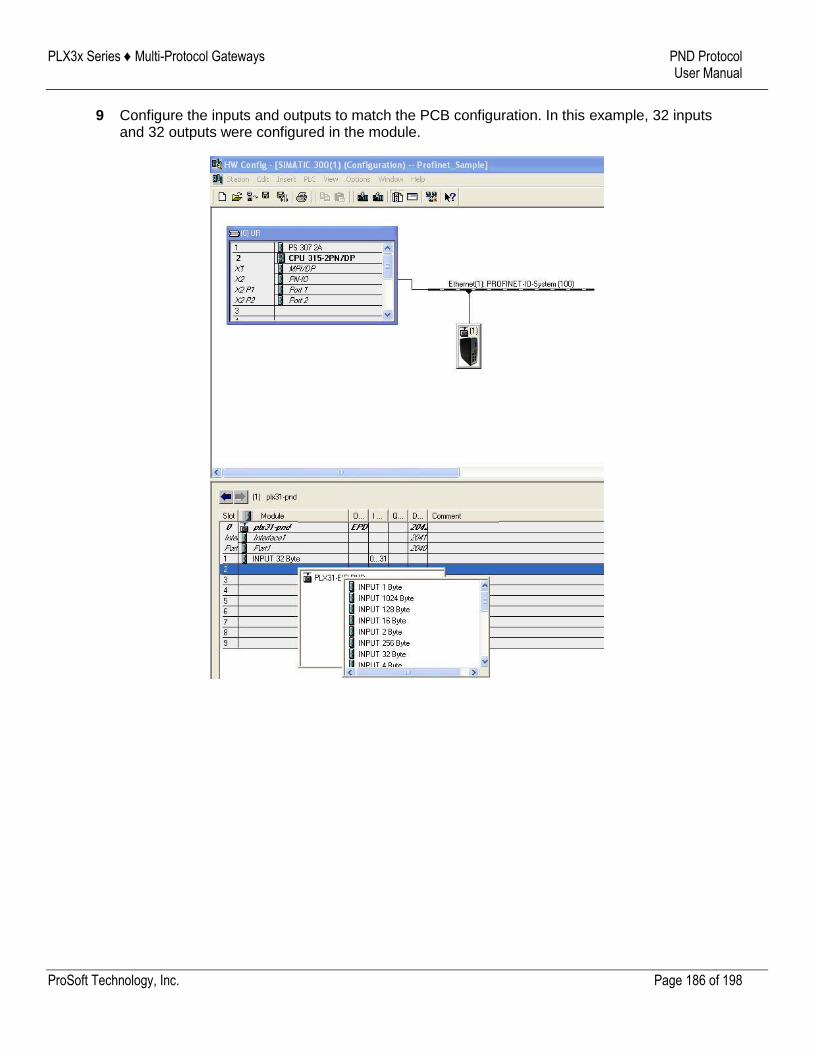
PLX3x Series ♦ Multi-Protocol Gateways PND Protocol User Manual
ProSoft Technology, Inc. Page 186 of 198
9 Configure the inputs and outputs to match the PCB configuration. In this example, 32 inputs and 32 outputs were configured in the module.
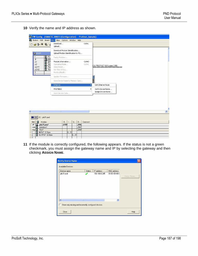
PLX3x Series ♦ Multi-Protocol Gateways PND Protocol User Manual
ProSoft Technology, Inc. Page 187 of 198
10 Verify the name and IP address as shown.
11 If the module is correctly configured, the following appears. If the status is not a green checkmark, you must assign the gateway name and IP by selecting the gateway and then clicking ASSIGN NAME.
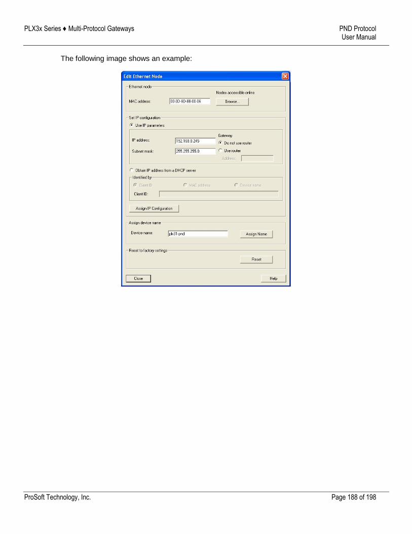
PLX3x Series ♦ Multi-Protocol Gateways PND Protocol User Manual
ProSoft Technology, Inc. Page 188 of 198
The following image shows an example:
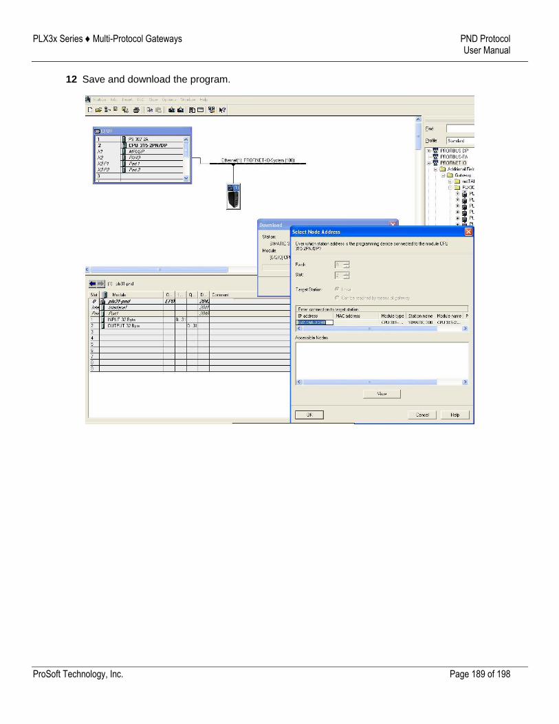
PLX3x Series ♦ Multi-Protocol Gateways PND Protocol User Manual
ProSoft Technology, Inc. Page 189 of 198
12 Save and download the program.
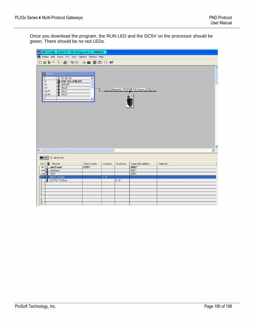
PLX3x Series ♦ Multi-Protocol Gateways PND Protocol User Manual
ProSoft Technology, Inc. Page 190 of 198
Once you download the program, the RUN LED and the DC5V on the processor should be green. There should be no red LEDs.
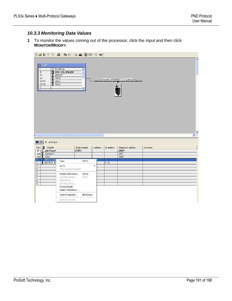
PLX3x Series ♦ Multi-Protocol Gateways PND Protocol User Manual
ProSoft Technology, Inc. Page 191 of 198
10.3.3 Monitoring Data Values
1 To monitor the values coming out of the processor, click the Input and then click MONITOR/MODIFY.
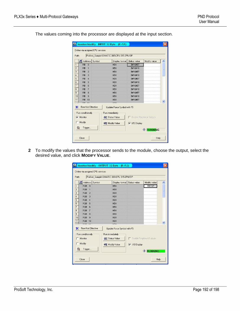
PLX3x Series ♦ Multi-Protocol Gateways PND Protocol User Manual
ProSoft Technology, Inc. Page 192 of 198
The values coming into the processor are displayed at the input section.
2 To modify the values that the processor sends to the module, choose the output, select the desired value, and click MODIFY VALUE.
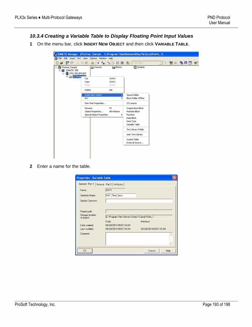
PLX3x Series ♦ Multi-Protocol Gateways PND Protocol User Manual
ProSoft Technology, Inc. Page 193 of 198
10.3.4 Creating a Variable Table to Display Floating Point Input Values
1 On the menu bar, click INSERT NEW OBJECT and then click VARIABLE TABLE.
2 Enter a name for the table.
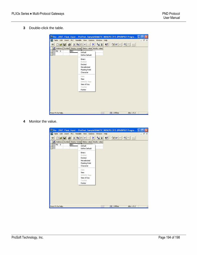
PLX3x Series ♦ Multi-Protocol Gateways PND Protocol User Manual
ProSoft Technology, Inc. Page 194 of 198
3 Double-click the table.
4 Monitor the value.
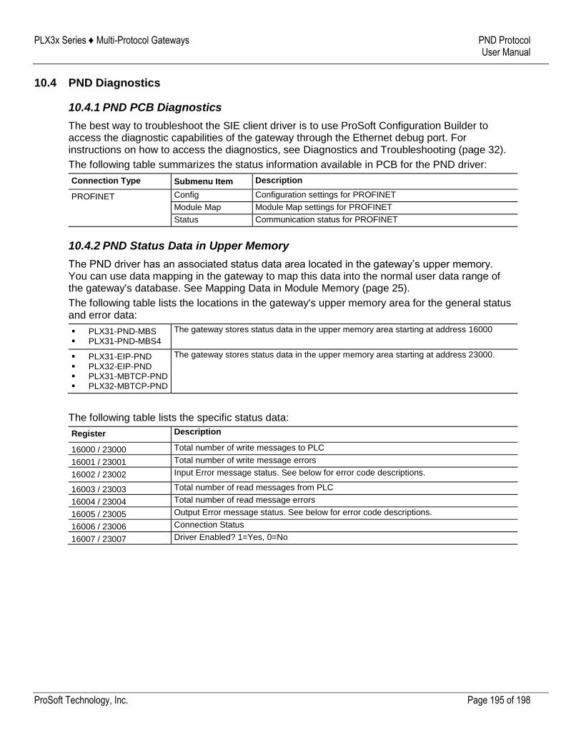
PLX3x Series ♦ Multi-Protocol Gateways PND Protocol User Manual
ProSoft Technology, Inc. Page 195 of 198
10.4 PND Diagnostics
10.4.1 PND PCB Diagnostics
The best way to troubleshoot the SIE client driver is to use ProSoft Configuration Builder to access the diagnostic capabilities of the gateway through the Ethernet debug port. For instructions on how to access the diagnostics, see Diagnostics and Troubleshooting (page 32).
The following table summarizes the status information available in PCB for the PND driver:
Connection Type Submenu Item Description
PROFINET Config Configuration settings for PROFINET
Module Map Module Map settings for PROFINET
Status Communication status for PROFINET
10.4.2 PND Status Data in Upper Memory
The PND driver has an associated status data area located in the gateway’s upper memory. You can use data mapping in the gateway to map this data into the normal user data range of the gateway's database. See Mapping Data in Module Memory (page 25).
The following table lists the locations in the gateway's upper memory area for the general status and error data:
PLX31-PND-MBS PLX31-PND-MBS4
The gateway stores status data in the upper memory area starting at address 16000
PLX31-EIP-PND PLX32-EIP-PND PLX31-MBTCP-PND PLX32-MBTCP-PND
The gateway stores status data in the upper memory area starting at address 23000.
The following table lists the specific status data:
Register Description
16000 / 23000 Total number of write messages to PLC
16001 / 23001 Total number of write message errors
16002 / 23002 Input Error message status. See below for error code descriptions.
16003 / 23003 Total number of read messages from PLC
16004 / 23004 Total number of read message errors
16005 / 23005 Output Error message status. See below for error code descriptions.
16006 / 23006 Connection Status
16007 / 23007 Driver Enabled? 1=Yes, 0=No
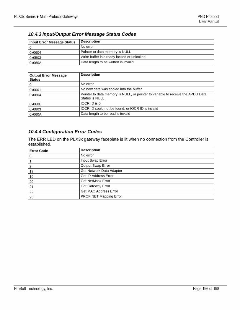
PLX3x Series ♦ Multi-Protocol Gateways PND Protocol User Manual
ProSoft Technology, Inc. Page 196 of 198
10.4.3 Input/Output Error Message Status Codes
Input Error Message Status Description
0 No error
0x0604 Pointer to data memory is NULL
0x0503 Write buffer is already locked or unlocked
0x060A Data length to be written is invalid
Output Error Message Status
Description
0 No error
0x0001 No new data was copied into the buffer
0x0604 Pointer to data memory is NULL, or pointer to variable to receive the APDU Data Status is NULL
0x060B IOCR ID is 0
0x0803 IOCR ID could not be found, or IOCR ID is invalid
0x060A Data length to be read is invalid
10.4.4 Configuration Error Codes
The ERR LED on the PLX3x gateway faceplate is lit when no connection from the Controller is established.
Error Code Description
0 No error
1 Input Swap Error
2 Output Swap Error
18 Get Network Data Adapter
19 Get IP Address Error
20 Get NetMask Error
21 Get Gateway Error
22 Get MAC Address Error
23 PROFINET Mapping Error
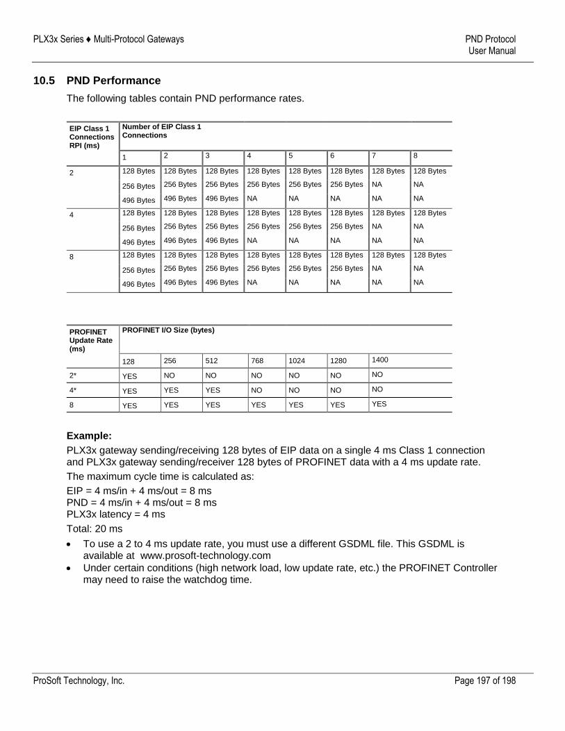
PLX3x Series ♦ Multi-Protocol Gateways PND Protocol User Manual
ProSoft Technology, Inc. Page 197 of 198
10.5 PND Performance
The following tables contain PND performance rates.
EIP Class 1 Connections RPI (ms)
Number of EIP Class 1 Connections
1 2 3 4 5 6 7 8
2 128 Bytes 128 Bytes 128 Bytes 128 Bytes 128 Bytes 128 Bytes 128 Bytes 128 Bytes
256 Bytes 256 Bytes 256 Bytes 256 Bytes 256 Bytes 256 Bytes NA NA
496 Bytes 496 Bytes 496 Bytes NA NA NA NA NA
4 128 Bytes 128 Bytes 128 Bytes 128 Bytes 128 Bytes 128 Bytes 128 Bytes 128 Bytes
256 Bytes 256 Bytes 256 Bytes 256 Bytes 256 Bytes 256 Bytes NA NA
496 Bytes 496 Bytes 496 Bytes NA NA NA NA NA
8 128 Bytes 128 Bytes 128 Bytes 128 Bytes 128 Bytes 128 Bytes 128 Bytes 128 Bytes
256 Bytes 256 Bytes 256 Bytes 256 Bytes 256 Bytes 256 Bytes NA NA
496 Bytes 496 Bytes 496 Bytes NA NA NA NA NA
PROFINET Update Rate (ms)
PROFINET I/O Size (bytes)
128 256 512 768 1024 1280 1400
2* YES NO NO NO NO NO NO
4* YES YES YES NO NO NO NO
8 YES YES YES YES YES YES YES
Example:
PLX3x gateway sending/receiving 128 bytes of EIP data on a single 4 ms Class 1 connection and PLX3x gateway sending/receiver 128 bytes of PROFINET data with a 4 ms update rate.
The maximum cycle time is calculated as:
EIP = 4 ms/in + 4 ms/out = 8 ms PND = 4 ms/in + 4 ms/out = 8 ms PLX3x latency = 4 ms
Total: 20 ms
To use a 2 to 4 ms update rate, you must use a different GSDML file. This GSDML is available at www.prosoft-technology.com
Under certain conditions (high network load, low update rate, etc.) the PROFINET Controller may need to raise the watchdog time.
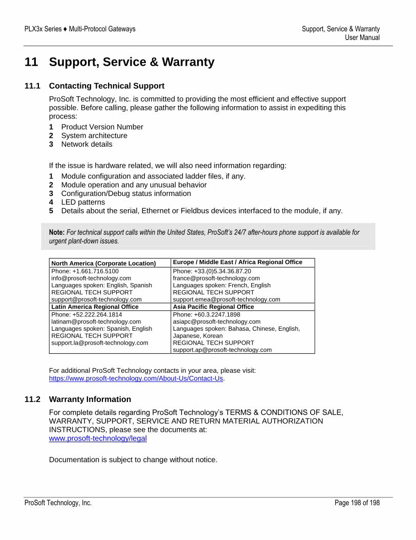
PLX3x Series ♦ Multi-Protocol Gateways Support, Service & Warranty User Manual
ProSoft Technology, Inc. Page 198 of 198
11 Support, Service & Warranty
11.1 Contacting Technical Support
ProSoft Technology, Inc. is committed to providing the most efficient and effective support possible. Before calling, please gather the following information to assist in expediting this process:
1 Product Version Number 2 System architecture 3 Network details
If the issue is hardware related, we will also need information regarding:
1 Module configuration and associated ladder files, if any. 2 Module operation and any unusual behavior 3 Configuration/Debug status information 4 LED patterns 5 Details about the serial, Ethernet or Fieldbus devices interfaced to the module, if any.
Note: For technical support calls within the United States, ProSoft’s 24/7 after-hours phone support is available for urgent plant-down issues.
North America (Corporate Location) Europe / Middle East / Africa Regional Office
Phone: +1.661.716.5100 [email protected] Languages spoken: English, Spanish REGIONAL TECH SUPPORT [email protected]
Phone: +33.(0)5.34.36.87.20 [email protected] Languages spoken: French, English REGIONAL TECH SUPPORT [email protected]
Latin America Regional Office Asia Pacific Regional Office
Phone: +52.222.264.1814 [email protected] Languages spoken: Spanish, English REGIONAL TECH SUPPORT [email protected]
Phone: +60.3.2247.1898 [email protected] Languages spoken: Bahasa, Chinese, English, Japanese, Korean REGIONAL TECH SUPPORT [email protected]
For additional ProSoft Technology contacts in your area, please visit: https://www.prosoft-technology.com/About-Us/Contact-Us.
11.2 Warranty Information
For complete details regarding ProSoft Technology’s TERMS & CONDITIONS OF SALE, WARRANTY, SUPPORT, SERVICE AND RETURN MATERIAL AUTHORIZATION INSTRUCTIONS, please see the documents at: www.prosoft-technology/legal
Documentation is subject to change without notice.
Related Documents