Installation Guide Update Alert: Firmware updates are posted the web on a regular basis. We recommend on that you check for firmware and/or install guide updates prior to installing this product. Vehicle Application Guide ....... .................. .... ................................. ............................... ...................................................... Installation s s (Wiring Diagram & Vehicle Wiring Reference Chart ) Type 1.............. ..... .......................................... .......................................................................... .......................................... Type .............. ..... .......................................... 2 .......................................................................... .......................................... Type .............. ..... .......................................... 3 .......................................................................... .......................................... Type 4................................................................................................................................................................................. Type 5.............. ..... .......................................... .......................................................................... .......................................... Type 6................................................................................................................................................................................ Programming Module Programming ...................... ....... ....................................................................... .......... ........................................... Module Reset.. ................................................................................................................................................................ ... Hard ... .... Reset.. ................................................................................................................................................................ Feature & Option List.......................................................................................................................................................... Feature Programming......................................................................................................................................................... LED Diagnostics & Troubleshooting................................................................................................................................... Limited One-Year Consumer ........ Warranty ....................................................................................................................... Quick Reference Guide...................................................................................................................................................... 02 03 05 07 09 11 13 15 16 16 17 17 18 20 21 Index ® Hyundai and Kia their respective companies are registered trademarks and property of . The HYUNDAI1 firmware for 2 is an all-in-one door lock and override module compatible with DBALL specific Hyundai and Kia vehicles. This module can only be flashed and configured using Xpress at www.directechs.com or VIP using the Directechs Mobile application for smartphones. Refer to the Module Programming section 15 on page for more information. Takeover feature is on the Kia Optima. The engine will stop when a door is opened. not available Rev.: 20170818 Platform: DBALL2 Firmware: HYUNDAI1 © 2017 Directed. All rights reserved.

Welcome message from author
This document is posted to help you gain knowledge. Please leave a comment to let me know what you think about it! Share it to your friends and learn new things together.
Transcript

Installation Guide
Update Alert: Firmware updates are posted the web on a regular basis. We recommendon
that you check for firmware and/or install guide updates prior to installing this product.
Vehicle Application Guide ....... .................. ..................................... ............................... ......................................................
Installation s s(Wiring Diagram & Vehicle Wiring Reference Chart )Type 1.............. ..... .................................................................................................................... ..........................................Type .............. ..... ..........................................2 .......................................................................... ..........................................Type .............. ..... ..........................................3 .......................................................................... ..........................................Type 4.................................................................................................................................................................................Type 5.............. ..... .................................................................................................................... ..........................................Type 6................................................................................................................................................................................
ProgrammingModule Programming ...................... .............................................................................. .......... ...........................................Module Reset.. ...................................................................................................................................................................Hard ... ....Reset.. ................................................................................................................................................................Feature & Option List..........................................................................................................................................................Feature Programming.........................................................................................................................................................
LED Diagnostics & Troubleshooting...................................................................................................................................
Limited One-Year Consumer ........Warranty.......................................................................................................................
Quick Reference Guide......................................................................................................................................................
02
030507091113
1516161717
18
20
21
Index
® Hyundai and Kia their respective companiesare registered trademarks and property of .
The HYUNDAI1 firmware for 2 is an all-in-one door lock and override module compatible withDBALLspecific Hyundai and Kia vehicles.
This module can only be flashed and configured using Xpress at www.directechs.com orVIPusing the Directechs Mobile application for smartphones. Refer to the Module Programmingsection 15on page for more information.
Takeover feature is on the Kia Optima. The engine will stop when a door is opened.not available
Rev.: 20170818
Platform: DBALL2
Firmware: HYUNDAI1
© 2017 Directed. All rights reserved.

Vehicle Application GuidePage 2
The following table lists the vehicles and features which are compatible with this product. The number assigned to eachyear allows you to determine which installation type should be used for your vehicle.
Vehicles
2015
2014
2013
2012
2011
2010
2009
PK
-Im
mobili
zer
Bypass-D
ata
No
Key
Req'd
AV
-Panic
Mode
Activation
DL-A
rmF
acto
ryS
ecurity
DL-D
isarm
Facto
ryS
ecurity
DL-D
oor
Lock
Contr
ol
DL-D
oor
Unlo
ck
DL-D
river
Priority
Unlo
ck
DL-T
runk
/H
atc
hR
ele
ase
FO
B-C
ontr
olof
aft
erm
ark
et
ala
rmw
ith
OE
Mre
mote
RS
-RA
PS
hut
Dow
n(R
eta
ined
AC
CP
ow
er)
RS
-Tach
/R
PM
Outp
ut
SS
-Entr
yM
onitoring
ALL
Door
Pin
s
SS
-Entr
yM
onitoring
Hood
Pin
SS
-Entr
yM
onitoring
Tru
nk/H
atc
hP
in
ST
-Bra
ke
Sta
tus
(foot
bra
ke)
ST
-E-B
rake
Sta
tus
ST
-Ignitio
nS
tatu
s
Hyundai
Genesis (Smart Key) 1 1 1 1 1 • • • • • • • • D • • • • • • • D
Genesis Coupe (Smart Key) 6 6 6 2 2 2 • • • • • • • • D • • • • • • • D
Sonata (Smart Key) 3 3 3 3 • • • • • • • • D • • • • • • • D
Sonata Hybrid 3 3 3 3 • • • • • • • • D • • • • • • • D
Kia 15 14 13 12 11 10 09
Magentis (Smart Key) 4 • • • • • • • • D • • • • • • • D
Optima (Smart Key) 4 • • • • • • • • D • • • • • • • D
Sorento (Smart Key) 5 5 5 • • • • • • • • D • • • • • • • D
Legend: PK: Transponder & Immobilizer Override
D: Data-to-Data (D2D) only AV: Horn & Lights Controls
•: D2D and W2W CC: Comfort & Convenience Controls
DL: OE Door Lock & Alarm Controls
FOB: Sync CAN Interface w / FOB Remote
RS: Remote Start & Engine Controls
SS: Integrated Security & Monitoring
ST: Function/Feature Status
Rev.: 20170818
Platform: DBALL2
Firmware: HYUNDAI1
© 2017 Directed. All rights reserved.
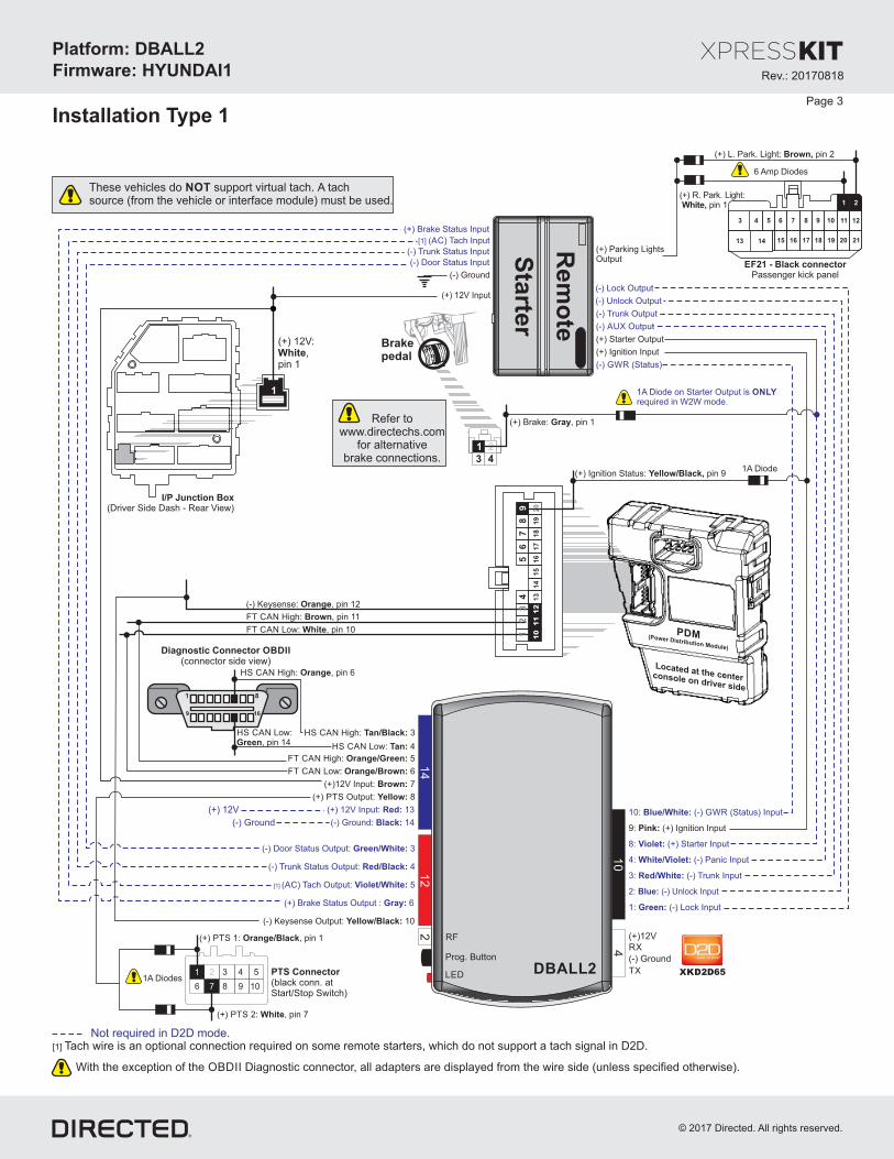
Page 3
Installation Type 1
PDM(Power Distribution Module)
[1] ( ) Tach InputAC
(-) Trunk Status Input
(-) Door Status Input
Rem
ote
Sta
rter
(-) (Status)GWR
(-) OutputLock
(-) OutputUnlock
(-) OutputAUX
(+) Starter Output
(-) OutputTrunk
( ) Parking ights+ LOutput
(+) R. Park. Light:pin 1White,
(+) L. Park. Light: pin 2Brown,
EF21 - Black connectorPassenger kick panel
(+) Ignition Input
(+) 12V Input
(-) Ground
1: (-) Lock InputGreen:
2: (-) Unlock InputBlue:
3: (-) Trunk InputRed/White:
4: (-) Panic InputWhite/Violet:
9: (+) Ignition InputPink:
8 Starter: (+) InputViolet:
10: (-) (Status) InputBlue/White: GWR
[1] ( ) Tach Output: 5AC Violet/White:
(-) Keysense Output: Yellow/Black: 10
(-) Door Status Output: 3Green/White:
(-) Trunk Status Output: 4Red/Black:
HS CAN High: , pin 6Orange
HS CAN Low:Green, pin 14
HS CAN High: 3Tan/Black:
FT CAN High: 5Orange/Green:
HS CAN Low: 4Tan:
FT CAN Low: 6Orange/Brown:
1 8
169
FT CAN High: , pin 11Brown
(-) Keysense: , pin 12Orange
(+) Ignition Status: pin 9Yellow/Black,
FT CAN Low: , pin 10White
(+) 12V:,White
pin 1
Located at the centerconsol on driver sidee
212017 18 1916151413
3 4 5 6 7 8 9 10 11 12
21
I/P Junction Box(Driver Side Dash - )Rear View
1
Brakepedal
2
4
1
3
(+) Brake: , pin 1Gray
Not required in D2D mode.
1A Diode Output ison Starter ONLYrequired in W2W mode.
12
34
67
8
13
9
17
20
12
16
19
11
15
18
10
14
5
(+) 12 : 13V Input Red:(+) 12V
(-) Ground: 14Black:(-) Ground
Diagnostic onnectorC OBDII(connector side view)
These vehicles do support virtual tach.NOT A tachsource (from the vehicle or module) must be usedinterface .
( ) :+ Brake Status Output 6Gr :ay
(+) Brake Status Input
Refer towww.directechs.com
for alternativebrake connections.
6 Amp Diodes
[1] Tach wire is an optional connection required on some remote starters, which do not support a tach signal in D2D.
With the exception of the Diag connector, all adapters are displayed from the wire side (unless specified otherwise).OB IID nostic
10
DBALL2
RF
Prog utton. B
LED
4
14
12
2
TX
(-) Ground
RX
(+)12V
XKD2D65
1A Diode
(+)12V Input 7: Brown:
(+) PTS Output 8: Yellow:
1A DiodesPTS Connector(black conn. atStart/Stop Switch)
(+) PTS 2: , pin 7White
(+) PTS 1: , pin 1Orange/Black
5
6 10987
1 432
Rev.: 20170818
Platform: DBALL2
Firmware: HYUNDAI1
© 2017 Directed. All rights reserved.

Rev.: 20170818
Platform: DBALL2
Firmware: HYUNDAI1
© 2017 Directed. All rights reserved.
Page 4
Type 1 - Vehicle Wiring Reference Chart
Function Color Pin Polarity Location Color Pins
Hyundai Genesis (Smart Key) 2009-2013
HS CAN High Orange 6 Data OBDll. Black 16
HS CAN Low Green 14 Data OBDll. Black 16
FT CAN High Brown 11 Data Power distribution module in center console on driver side. White 20
FT CAN Low White 10 Data Power distribution module in center console on driver side. White 20
Keysense Orange 12 (-) Power distribution module in center console on driver side. White 20
Ignition Yellow/Black 9 (+) Power distribution module in center console on driver side. White 20
Brake Gray 1 (+) Brake switch. White 4
Parking Lights (Left) Brown 2 (+) Passenger kick. Black 21
Parking Lights (Right) White 1 (+) Passenger kick. Black 21
12 Volts White 1 (+) Drivers dash fuse box. White 1
PTS 1 Orange/Black 1 (+) Start/stop switch. Black 10
PTS 2 White 7 (+) Start/stop switch. Black 10
Wire Information Connector Information

Rev.: 20170818
Platform: DBALL2
Firmware: HYUNDAI1
© 2017 Directed. All rights reserved.
Brakepedal
15
37
26
48
9
10
14
12
16
11
15
13
17
18
87
65
43
21
20
19
18
17
16
13
12
11
10
91
51
4
76
54
32
11
81
71
6
11
14
13
12
11
10
98
15
65
43
21
16
14
15
13
12
11
10
97
8
Not required in D2D mode.
87
86 85
30
87A
[2] (-) Clutch:, pin 1Green
21
Clutch Pedal
(-) KeySense : pin 12Red,
[1] ( ) Tach InputAC
(-) Trunk Status Input(-) Door Status Input
Rem
ote
Sta
rter
(-) Parking Lights Output
(+) 12V Input
(-) rake StatusE-B Input
(+) 12V
(-) Ground
(-) Ground
(-) Hood Status Input
[1] ( ) Tach Output: 5AC Violet/White:
(-) Keysense Output: Yellow/Black: 10
[2]( ) Clutch Relay Output+ : 7Gray/Black:
(-) Door Status Output: 3Green/White:
(-) Trunk Status Output: 4Red/Black:
High: pin 6HS CAN Red,
HS CAN Low:Blue, pin 14
(+) 12 : 13V Input Red:
(-) Ground: 14Black:
HS CAN High: 3Tan/Black:
FT CAN High: 5Orange/Green:
HS CAN Low: 4Tan:
FT CAN Low: 6Orange/Brown:
1 8
169
(-)
Park
ing L
ights
:pin
8B
row
n/B
lack,
(+) Ignition
Status: Blue,
pin 15
(+) 12V:Red,
pin 14
(-)
E-B
rake S
tatu
s:
Bro
wn
/Ora
ng
e4
, p
in
FT CAN Low:pin 10Blue,
FT CAN High:pin 11Red,
(-) Hood Status: pin 31Yellow,
1 11
15 25
29 39
2 12
16 26
30 40
3 13 144 86 105 97
18 2220 2419 2321
32 3634 3833 3735
17 27 28
31 41 42
Driver SideKick Panel
Blue Connector
I/ - Driver Side Fuse BoxP(see back of I/P)
1: (-) Lock InputGreen:
2: (-) Unlock InputBlue:
3: (-) Trunk InputRed/White:
4: (-) Panic InputWhite/Violet:
9: (+) Ignition InputPink:
8 Starter: (+) InputViolet:
10: (-) (Status) InputBlue/White: GWR
(-) (Status)GWR
(-) OutputLock
(-) OutputUnlock
(-) OutputAUX
(+) Starter Output
(-) OutputTrunk
(+) Ignition Input( ) E-B wire is- rake
inconnected onlyvehicles equippedwith manualatransmission.
(+) Starter wire isconnected to theBrake Pedal connectorfor vehicles equippedwith an automatictransmission .only
A B
C C
D
D
G
A
1A Diode ison Starter wire ONLYrequired in W2W mode.
1 2 3 4
These vehicles do support virtual tach.NOT A tachsource (from the vehicle or module) must be usedinterface .
Diagnostic onnectorC OBDII(connector side view)
Ground
( ) :+ Brake Status Output 6Gr :ay
(+) Brake Status Input
12
34
67
8
13
9
17
20
12
16
19
11
15
18
10
14
5
PDM(Power Distribution Module)
Located at the centerconsol on driver sidee
(+) Brake:pin 1Green,
[1] Tach wire is an optional connection required on some remote starters, which do not support a tach signal in D2D.
Installation Type 2
With the exception of the Diag connector, all adapters are displayed from the wire side (unless specified otherwise).OB IID nostic
[2] ( ) wire is connected to connector s equipped a+ Clutch Relay Clutch Pedal for vehicle with manual transmission .only
10
DBALL2
RF
LED
4
14
12
2
XKD2D65TX
(-) Ground
RX
(+)12V
Prog utton. B
G
(+)12V Input 7: Brown:
(+) PTS Output 8: Yellow:
1A Diode
1A Diodes
PTS Connector( )black conn. at Start/Stop Switch
(+) PTS 2:Pink, pin 7
(+) PTS 1:Blue, pin 1
5
6 10987
1 432
Page 5

Rev.: 20170818
Platform: DBALL2
Firmware: HYUNDAI1
© 2017 Directed. All rights reserved.
Type 2 - Vehicle Wiring Reference Chart
Function Color Pin Polarity Location Color Pins
Hyundai Genesis Coupe (Smart Key) 2010-2012
HS CAN High Red 6 Data OBDll. Black 16
HS CAN Low Blue 14 Data OBDll. Black 16
FT CAN High Red 11 Data Power distribution module in center console on driver side. White 20
FT CAN Low Blue 10 Data Power distribution module in center console on driver side. White 20
Keysense Red 12 (-) Power distribution module in center console on driver side. White 20
Ignition Blue 15 (+) Drivers dash fuse box. White 18
Brake Green 1 (+) Brake switch. White 4
Parking Lights Brown/Black 8 (-) Drivers dash fuse box. White 16
12 Volts Red 14 (+) Drivers dash fuse box. White 20
E-Brake Brown/Orange 4 (-) Drivers dash fuse box. Blue 14
Hood pin Yellow 31 (-) Drivers kick. Blue 42
Clutch Green 1 (-) Clutch pedal. White 2
PTS 1 Blue 1 (+) Start/stop switch. Black 10
PTS 2 Pink 7 (+) Start/stop switch. Black 10
Wire Information Connector Information
Page 6

Rev.: 20170818
Platform: DBALL2
Firmware: HYUNDAI1
© 2017 Directed. All rights reserved.
39
50 23
54 26
51 24
55 27
52 25
53 17
56 28
41 14
45 18
42 15
46 19
43 16
44 6
47 20
31 3
34 7
32 4
35 8
33 5
36 9
48
12
21
40
49
13
22
29
37
1
10
30
38
2
11
[1] ( ) Tach InputAC
(-) Trunk Status Input(-) Door Status Input
Rem
ote
Sta
rter
( ) Park ghts- .Li Ouput
(-) Ground
(+) 12V Input
HS CAN High: , pin 6White
(-) Keysense:Yellow orOrange/Black,pin 41
OR
(-) KeysenseYellow(Hybrid),pin 47
FT CAN High:White/Orange or
Blue (Hybrid), pin 12
FT CAN Low:Yellow/Orange or
Orange (Hybrid), pin 11
HS CAN Low:Yellow or
Brown (Hybrid),pin 14
(+) 12V (+) 12 13V Red:
(-) Ground (-) Ground: 14Black:
HS CAN High: 3Tan/Black:
FT CAN High: 5Orange/Green:
HS CAN Low: 4Tan:
FT CAN Low: 6Orange/Brown:
1 8
169
I/ - Driver SideP Junction Box Dash( )front view
White/Gray Connector(Passenger Kick Panel or in
Driver Kick Panel for the Hybrid)
27
28 15 2
32 19 6
30 17 4
34 21 8
37 24 11
29 16 3
33 20 7
36 23 10
31 18 5
35 22 9
38 25 12
39
14
26
1
13
(+)1
2V
:pin
13
Red
,
21
22 12 2
26 16 6
34 14 4
28 18 8
23 13 3
27 17 7
25 15 5
29 19 9
30
11
20
1
13
I/P Junction Box -Driver Side Dash
( /P )see back of I Junction Box
(-) (Status)GWR
(-) OutputLock
(-) OutputUnlock
(-) OutputAUX
(+) Starter Output
(-) OutputTrunk
(+) Ignition Input
13
17
21
15
19
23
14
18
22
16
20
24
1
5
9
3
7
11
2
6
10
4
8
12
Brakepedal
2
4
1
3
1A Diode on Starteriswire ONLY
required inW2W mode.
Not required in D2D mode.
These vehicles do support virtualNOTA tach source (from the vehicletach.
or module) must be usedinterface .
(+) Ignition Status:, pin 11Pink
(-) Parking Lights:pin 22Pink,
BCM Above Gas Pedal-
1218 1319 1420 1521 1622 172324
1234567891011
1: (-) Lock InputGreen:
2: (-) Unlock InputBlue:
3: (-) Trunk InputRed/White:
4: (-) Panic InputWhite/Violet:
9: (+) Ignition InputPink:
8 Starter: (+) InputViolet:
10: (-) (Status) InputBlue/White: GWR
Diagnostic onnectorC OBDII(connector side view)
(+) Brake:Green orGreen/Orange(Hybrid),pin 1
(+) Brake Status Input
Installation Type 3
[1] Tach wire is an optional connection required on some remote starters, which do not support a tach signal in D2D.
With the exception of the Diag connector, all adapters are displayed from the wire side (unless specified otherwise).OB IID nostic
10
DBALL2
RF
LED
4
14
12
2
TX
(-) Ground
RX
(+)12V
XKD2D65Prog utton. B
[1] ( ) Tach Output: 5AC Violet/White:
(-) Keysense Output: Yellow/Black: 10
(-) Door Status Output: 3Green/White:
(-) Trunk Status Output: 4Red/Black:
( ) :+ Brake Status Output 6Gr :ay
(+)12V Input 7: Brown:
(+) PTS Output 8: Yellow:
1A Diodes
PTS Connector(black conn. at
Start/Stop Switch)
(+) PTS 2:Yellow/Orange,pin 7
(+) PTS 1:Yellow/Black,
pin 1
5
6 10987
1 432
1A Diode
Page 7
Rev.: 20170818
Platform: DBALL2
Firmware: HYUNDAI1
© 2017 Directed. All rights reserved.
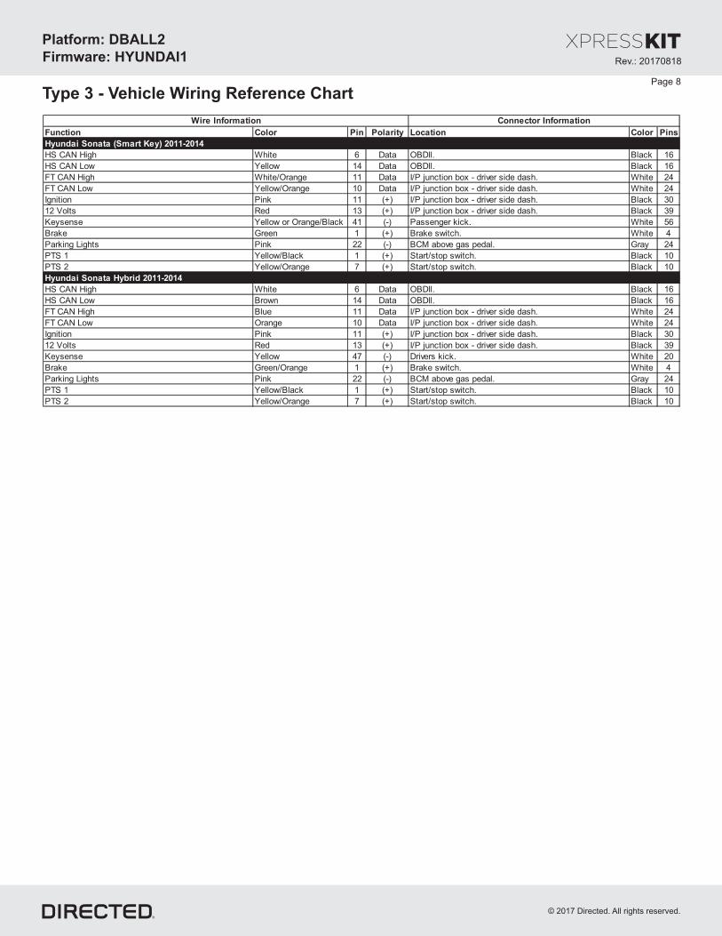
Type 3 - Vehicle Wiring Reference Chart
Function Color Pin Polarity Location Color Pins
Hyundai Sonata (Smart Key) 2011-2014
HS CAN High White 6 Data OBDll. Black 16
HS CAN Low Yellow 14 Data OBDll. Black 16
FT CAN High White/Orange 11 Data I/P junction box - driver side dash. White 24
FT CAN Low Yellow/Orange 10 Data I/P junction box - driver side dash. White 24
Ignition Pink 11 (+) I/P junction box - driver side dash. Black 30
12 Volts Red 13 (+) I/P junction box - driver side dash. Black 39
Keysense Yellow or Orange/Black 41 (-) Passenger kick. White 56
Brake Green 1 (+) Brake switch. White 4
Parking Lights Pink 22 (-) BCM above gas pedal. Gray 24
PTS 1 Yellow/Black 1 (+) Start/stop switch. Black 10
PTS 2 Yellow/Orange 7 (+) Start/stop switch. Black 10
Hyundai Sonata Hybrid 2011-2014
HS CAN High White 6 Data OBDll. Black 16
HS CAN Low Brown 14 Data OBDll. Black 16
FT CAN High Blue 11 Data I/P junction box - driver side dash. White 24
FT CAN Low Orange 10 Data I/P junction box - driver side dash. White 24
Ignition Pink 11 (+) I/P junction box - driver side dash. Black 30
12 Volts Red 13 (+) I/P junction box - driver side dash. Black 39
Keysense Yellow 47 (-) Drivers kick. White 20
Brake Green/Orange 1 (+) Brake switch. White 4
Parking Lights Pink 22 (-) BCM above gas pedal. Gray 24
PTS 1 Yellow/Black 1 (+) Start/stop switch. Black 10
PTS 2 Yellow/Orange 7 (+) Start/stop switch. Black 10
Wire Information Connector Information
Page 8

Rev.: 20170818
Platform: DBALL2
Firmware: HYUNDAI1
© 2017 Directed. All rights reserved.
Brakepedal
(+) Brake: ,Brownpin 1
[1] ( ) Tach InputAC
(-) Trunk Status Input(-) Door Status Input
Rem
ote
Sta
rter
( ) Parking ights- L Output
(+) 12V
(-) Ground
(-) Ground
(-) Hood Status Input
[1] ( ) Tach Output: 5AC Violet/White:
(-) Output: 12Autolight Off Blue/Red:
(-) Output:Keysense 10Yellow/Black:
(-) Door Status Output: 3Green/White:
(-) Trunk Status Output: 4Red/Black:
(+) 12V Input
HS CAN High:White, pin 6
HS CAN Low:pin 14Black,
(+) 12 : 13V Red:
(-) Ground: 14Black:
HS CAN High: 3Tan/Black:
FT CAN High: 5Orange/Green:
HS CAN Low: 4Tan:
FT CAN Low: 6Orange/Brown:
1 8
169
1: (-) Lock InputGreen:
2: (-) Unlock InputBlue:
3: (-) Trunk InputRed/White:
4: (-) Panic InputWhite/Violet:
9: (+) Ignition InputPink:
8 Starter: (+) InputViolet:
10: (-) (Status) InputBlue/White: GWR
(-) (Status)GWR
(-) OutputLock
(-) OutputUnlock
(-) OutputAUX
(+) Starter Output
(-) OutputTrunk
(+) Ignition Input
FT CAN High:White, pin 5
FT CAN Low:Black, pin 15
7
17159 10 11 12
1 2 3 4 5
13
6 8
16 1814
C
(-) Driver Door Trigger:Blue/Black,
pin 20
(+) Ignition Status: ,Yellow/Black pin 2
11
24
10
23
9
22
8
21
7
201812 13 14 15
1 2 3 4 5
16
6
1917
A
(+) 12V:Red, pin 1
I/P Box(Above Driver
Kick Panel)Connector G
4321
G
(-) Keysense:9Orange, pin
Key Port - UnderCenter Arm Rest
(-) Hood Status:Yellow/Black,pin 13 (-) Parking Lights
,Yellow/Blackpin 4
7 9
18 201610 11 12 13
1 2 3 4 5
14
6 8
17 1915
B
1A Diode is required inon Starter wire ONLYW2W mode.
2
4
1
3
BCM(Above Brake Pedal)
A
B
C
1
6 87 9 10
5
Not required in D2D mode.
These vehicles do support virtualNOTA tach source (from the vehicletach.
or module) must be usedinterface .
Diagnostic onnectorC OBDII(connector side view)
( ) :+ Brake Status Output 6Gr :ay
(+) Brake Status Input
32 4
(+)12V Input 7: Brown:
(+) PTS Output 8: Yellow:
Installation Type 4
[1] Tach wire is an optional connection required on some remote starters, which do not support a tach signal in D2D.
With the exception of the Diag connector, all adapters are displayed from the wire side (unless specified otherwise).OB IID nostic
10
2DBALL
RF
LED
4
14
12
2
TX
(-) Ground
RX
(+)12V
XKD2D65
Prog utton. B
1A Diode
1A Diodes
(+) PTS 2:Whit/Orange,pin 7
(+) PTS 1:Orange/Black,
pin 15
6 10987
1 432
PTS Connector(black conn. atStart/Stop Switch)
Page 9

Rev.: 20170818
Platform: DBALL2
Firmware: HYUNDAI1
© 2017 Directed. All rights reserved.
Type 4 - Vehicle Wiring Reference Chart
Function Color Pin Polarity Location Color Pins
Kia Magentis (Smart Key) 2010
HS CAN High White 6 Data OBDll. Black 16
HS CAN Low Black 14 Data OBDll. Black 16
FT CAN High White 5 Data BCM above Brake pedal. Gray 18
FT CAN Low Black 15 Data BCM above Brake pedal. Gray 18
Ignition Yellow/Black 2 (+) BCM above Brake pedal. White 24
Driver Door Trigger Blue/Black 20 (-) BCM above Brake pedal. White 24
Parking Lights Yellow/Black 4 (-) BCM above Brake pedal. White 20
Hood Pin Yellow/Black 13 (-) BCM above Brake pedal. White 20
12 Volts Red 1 (+) I/P Junction box above driver kick. White 4
Keysense Orange 9 (-) Key port in center console. White 10
Brake Brown 1 (+) Brake switch. White 4
PTS 1 Orange/Black 1 (+) Start/stop switch. Black 10
PTS 2 White/Orange 7 (+) Start/stop switch. Black 10
Kia Optima (Smart Key) 2010
HS CAN High White 6 Data OBDll. Black 16
HS CAN Low Black 14 Data OBDll. Black 16
FT CAN High White 5 Data BCM above Brake pedal. Gray 18
FT CAN Low Black 15 Data BCM above Brake pedal. Gray 18
Ignition Yellow/Black 2 (+) BCM above Brake pedal. White 24
Driver Door Trigger Blue/Black 20 (-) BMC above Brake pedal. White 24
Parking Lights Yellow/Black 4 (-) BCM above Brake pedal. White 20
Hood Pin Yellow/Black 13 (-) BCM above Brake pedal. White 20
12 Volts Red 1 (+) I/P Junction box above driver kick. White 4
Keysense Orange 9 (-) Key Port - IN Center Console White 10
Brake Brown 1 (+) Brake switch. White 4
PTS 1 Orange/Black 1 (+) Start/stop switch. Black 10
PTS 2 White/Orange 7 (+) Start/stop switch. Black 10
Wire Information Connector Information
Page 10

Rev.: 20170818
Platform: DBALL2
Firmware: HYUNDAI1
© 2017 Directed. All rights reserved.
(+) Brake:Yellow or
Green/Black,pin 1
26 1624
11
21
813 3
25 1523
10
20
7
18
5
1422
9
19
6
17
412 2 1
15
7
11
3
13
5
9
1
16
8
12
4
14
6
10
2
[1] ( ) Tach InputAC
(-) Trunk Status Input(-) Door Status Input
Rem
ote
Sta
rter
( ) Parking ights- L Output
(-) Hood Status Input
(+) 12V Input
HS CAN High: , pin 6White
(-) Keysense:Red orRed/Orange, pin 8
FT CAN High:Blue, pin 5
(-) Driver Door Trigger: pin 10Green/Orange,
(-) Hood Status:Red/Black,pin 16
FT CAN Low:Red, pin 6
1 8
169
(-) Pk Lights: , pin 2Blue
IPM Dash- Driver Side( )front view
(+)
12
V:
pin
4R
ed
,
1 2
6 7 8 9 10
3
5
4
11
1 4
17
7
20
12
14 25
2 5
18
8
21
10
23
13
15 26
3 6
19
9
22
11
2416
1
11
3
13
5
15
7
17
9
19
2
12
4
14
6
16
8
18
10
20
(+) Ignition Status:pin 17Green,
WhiteConnector
1
11
5
15
3
13
7
17
9
19
2
12
6
16
4
14
8
18
10
20
White Connector
IPM - Driver Side Dash(White connectorback of IPM)
WhiteConnector
RedConnector
IPM - Driver Side DashYellow (see back of )IPM
White Connector
(-) (Status)GWR
(-) OutputLock
(-) OutputUnlock
(-) OutputAUX
(+) Starter Output
(-) OutputTrunk
(+) Ignition Input
Brakepedal
2
4
1
3
Not required in D2D mode.
These vehicles do support virtualNOTA tach source (from the vehicletach.
or module) must be usedinterface .
(+) 12V (+) 12 : 13V Red:
(-) Ground (-) Ground: 14Black:
HS CAN High: 3Tan/Black:
FT CAN High: 5Orange/Green:
HS CAN Low: 4Tan:
FT CAN Low: 6Orange/Brown:
[1] ( ) Tach Output: 5AC Violet/White:
(-) Output: 12Autolight Off Blue/Red:
(-) Keysense Output: Yellow/Black: 10
(-) Door Status Output: 3Green/White:
(-) Trunk Status Output: 4Red/Black:
(-) Ground
1: (-) Lock InputGreen:
2: (-) Unlock InputBlue:
3: (-) Trunk InputRed/White:
4: (-) Panic InputWhite/Violet:
9: (+) Ignition InputPink:
8 Starter: (+) InputViolet:
10: (-) (Status) InputBlue/White: GWR
Diagnostic onnectorC OBDII(connector side view)
HS CAN Low:Red, pin 14
( ) :+ Brake Status Output 6Gr :ay
(+) Brake Status Input
Refer towww.directechs.com
for alternativebrake connections.
1A Diode onisStarter wire
ONLYrequired inW2W mode.
Installation Type 5
[1] Tach wire is an optional connection required on some remote starters, which do not support a tach signal in D2D.
With the exception of the Diag connector all adapters are displayed from the wire side (unless specified otherwise).OB IID nostic
10
2DBALL
RF
LED
4
14
12
2
TX
(-) Ground
RX
(+)12V
XKD2D65
Prog utton. B
1A Diode
(+)12V Input 7: Brown:
(+) PTS Output 8: Yellow:
1A DiodesPTS Connector(black conn. atStart/Stop Switch)
(+) PTS 2: , pin 7White/Orange
(+) PTS 1: , pin 1Orange/Black
5
6 10987
1 432
Page 11
Rev.: 20170818
Platform: DBALL2
Firmware: HYUNDAI1
© 2017 Directed. All rights reserved.
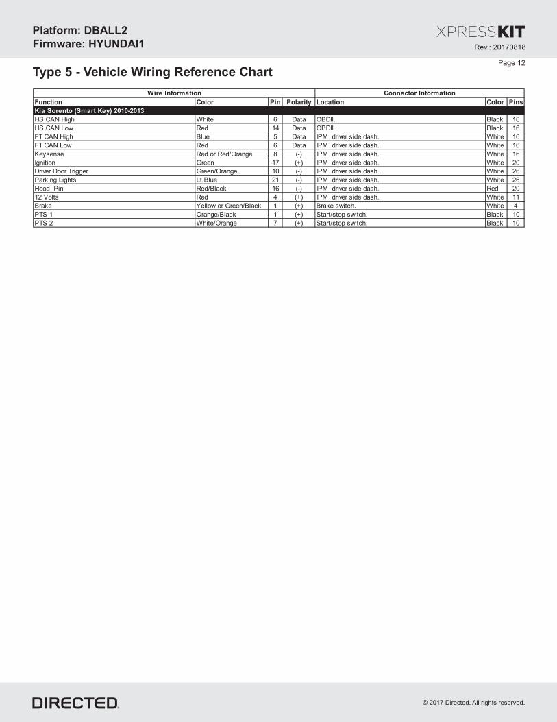
Type 5 - Vehicle Wiring Reference Chart
Function Color Pin Polarity Location Color Pins
Kia Sorento (Smart Key) 2010-2013
HS CAN High White 6 Data OBDll. Black 16
HS CAN Low Red 14 Data OBDll. Black 16
FT CAN High Blue 5 Data IPM driver side dash. White 16
FT CAN Low Red 6 Data IPM driver side dash. White 16
Keysense Red or Red/Orange 8 (-) IPM driver side dash. White 16
Ignition Green 17 (+) IPM driver side dash. White 20
Driver Door Trigger Green/Orange 10 (-) IPM driver side dash. White 26
Parking Lights Lt.Blue 21 (-) IPM driver side dash. White 26
Hood Pin Red/Black 16 (-) IPM driver side dash. Red 20
12 Volts Red 4 (+) IPM driver side dash. White 11
Brake Yellow or Green/Black 1 (+) Brake switch. White 4
PTS 1 Orange/Black 1 (+) Start/stop switch. Black 10
PTS 2 White/Orange 7 (+) Start/stop switch. Black 10
Wire Information Connector Information
Page 12

Rev.: 20170818
Platform: DBALL2
Firmware: HYUNDAI1
© 2017 Directed. All rights reserved.
2
4
1
3
36
17
18
28
38
27
37
10
26
89
35
1625
7
34
1524
6
33
1423
5
32
1322
4
31
12
11
19
29
21
32
1
30
20
151614131211109876542 31
32313029282726252423222120191817
10987654321
11 12 13 161514
Brakepedal
Not required in D2D mode.
85
87
86
30
87A [2] (-) Clutch:pin 1Green,
21
Clutch Pedal
(-) Keysense:pin 12Pink,
FT CAN Low:pin 16Blue,
FT CAN High:pin 15Red,
[1] ( ) Tach InputAC
(-) Trunk Status Input(-) Door Status Input
Rem
ote
Sta
rter
(-) Parking ightL Output
(+) 12V Input
(-) rake StatusE-B Input
(-) Ground
HS CAN High: pin 6Red,
HS CAN Low:Blue, pin 14
1 8
169
(-)
Park
ing L
ights
:pin
1Y
ello
w,
(+) Ignition Status: pin 4Green,
(+)
12V
:pin
29
Gre
en
,
(-)
E-B
rake:B
row
n/O
ran
ge,
pin
22
I/ - DP
(-) (Status)GWR
(-) OutputLock
(-) OutputUnlock
(-) OutputAUX
(+) Starter Output
(-) OutputTrunk
(+) Ignition Input
( ) E-B wire is- rakeinconnected only
vehicles equippedwith manualatransmission.
These vehicles do support virtual tach.NOT A tachsource (from the vehicle or module) must be usedinterface .
(-) Hood Status Input
PDM - Above Gas PedalWhite Connector
I/P-E I/P-G
I/P-D
14
13
12
11
10
98
76
54
32
1
28
27
26
25
24
23
22
21
20
19
18
17
16
15
I/ -P G
10
11
12
13
98
76
54
32
1
M48 - LParking Light
Connector
I/ -P EI/ -P A
I/P Junction Box,(Driver Side Dash - )Rear View
1: (-) Lock InputGreen:
2: (-) Unlock InputBlue:
3: (-) Trunk InputRed/White:
4: (-) Panic InputWhite/Violet:
9: (+) Ignition InputPink:
8 Starter: (+) InputViolet:
10: (-) (Status) InputBlue/White: GWR(+) 12V (+) 12 : 13V Red:
(-) Ground (-) Ground: 14Black:
HS CAN High: 3Tan/Black:
FT CAN High: 5Orange/Green:
HS CAN Low: 4Tan:
FT CAN Low: 6Orange/Brown:
97
2016 181411
865
191512 171310
2 3 41
[1] ( ) Tach Output: 5AC Violet/White:
(-) Keysense Output: Yellow/Black: 10
[2]( ) Clutch Relay Output+ : 7Gray/Black:
(-) Door Status Output: 3Green/White:
(-) Trunk Status Output: 4Red/Black:
Diagnostic onnectorC OBDII(connector side view)
1A Diode on Starteriswire ONLY
required inW2W mode.
Ground
( ) :+ Brake Status Output 6Gr :ay
Refer to www.directechs.comfor alternative brake connections.
(+) Starter wire is connected to the BrakePedal connector for vehicles equipped withan automatic transmission .only
I/P-A
(+)Brake:Red/Black,pin 1
(+)12V Input 7: Brown:
(+) PTS Output 8: Yellow:
1A Diode
PTS Connector(black conn. at
Start/Stop Switch)
(+) PTS 2:White/Orange,pin 7
(+) PTS 1:Orange/Black,
pin 1
5
6 10987
1 432
1ADiodes
Page 13
Installation Type 6
10
2DBALL
RF
LED
4
14
12
2
TX
(-) Ground
RX
(+)12V
XKD2D65
Prog utton. B
[1] Tach wire is an optional connection required on some remote starters, which do not support a tach signal in D2D.
With the exception of the Diag connector, all adapters are displayed from the wire side (unless specified otherwise).OB IID nostic
[2] ( ) wire is connected to connector s equipped a+ Clutch Relay Clutch Pedal for vehicle with manual transmission .only
Rev.: 20170818
Platform: DBALL2
Firmware: HYUNDAI1
© 2017 Directed. All rights reserved.
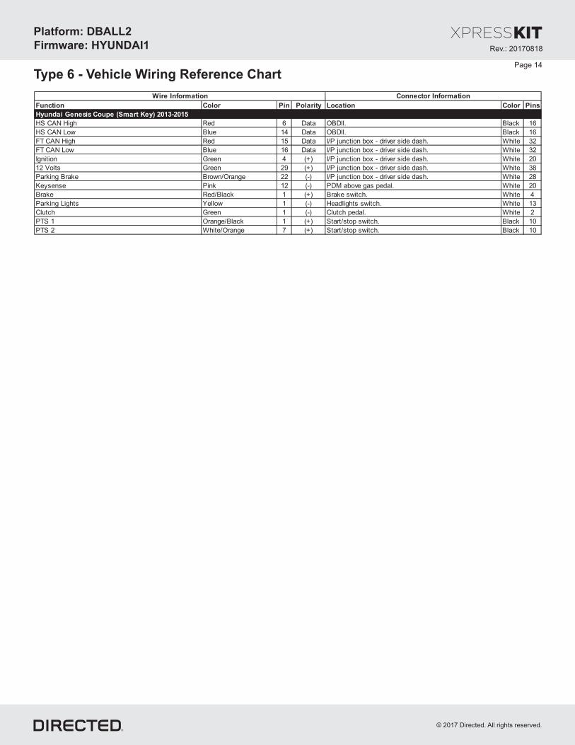
Type 6 - Vehicle Wiring Reference Chart
Function Color Pin Polarity Location Color Pins
Hyundai Genesis Coupe (Smart Key) 2013-2015
HS CAN High Red 6 Data OBDll. Black 16
HS CAN Low Blue 14 Data OBDll. Black 16
FT CAN High Red 15 Data I/P junction box - driver side dash. White 32
FT CAN Low Blue 16 Data I/P junction box - driver side dash. White 32
Ignition Green 4 (+) I/P junction box - driver side dash. White 20
12 Volts Green 29 (+) I/P junction box - driver side dash. White 38
Parking Brake Brown/Orange 22 (-) I/P junction box - driver side dash. White 28
Keysense Pink 12 (-) PDM above gas pedal. White 20
Brake Red/Black 1 (+) Brake switch. White 4
Parking Lights Yellow 1 (-) Headlights switch. White 13
Clutch Green 1 (-) Clutch pedal. White 2
PTS 1 Orange/Black 1 (+) Start/stop switch. Black 10
PTS 2 White/Orange 7 (+) Start/stop switch. Black 10
Wire Information Connector Information
Page 14
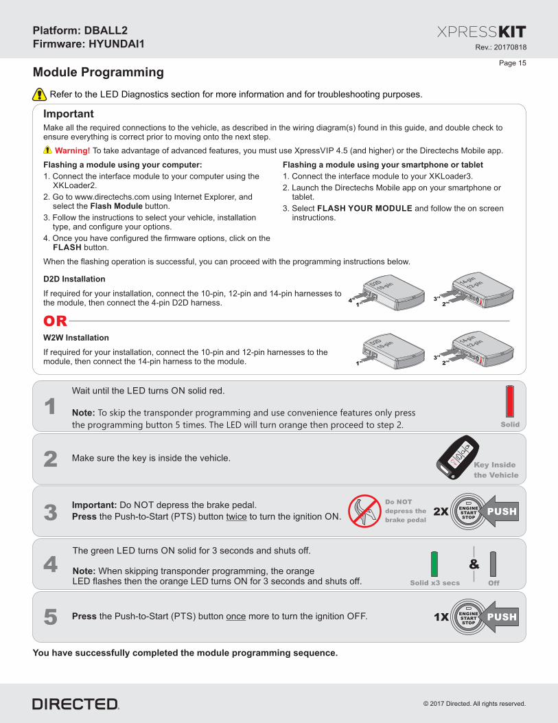
Module ProgrammingPage 15
Important
Make all the required connections to the vehicle, as described in the wiring diagram(s) found in this guide, and double check toensure everything is correct prior to moving onto the next step.
Warning! To take advantage of advanced features, you must use Xpress 4.5 (and higher) or the Directechs Mobile app.VIP
When the flashing operation is successful, you can proceed with the programming instructions below.
Refer to the Diagnostics section for more information and for troubleshooting purposes.LED
OR
If required for your installation, connect the 10-pin, 12-pin and 14-pin harnesses tothe module, then connect the 4-pin D2D harness.
D2D Installation
W W Installation2
If required for your installation, connect the 10-pin and 12-pin harnesses to themodule, then connect the 14-pin harness to the module.
10-pinD2D
1st
12-pin14-pin
2nd
3rd
10-pinD2D
1st
4th
12-pin14-pin
2nd
3rd
Flashing a module using your computer:
1. Connect the interface module to your computer using theXKLoader2.
2. Go to www.directechs.com using Internet Explorer, andselect the button.Flash Module
3. Follow the instructions to select your vehicle, installationtype, and configure your options.
4. Once you have configured the firmware options, click on theFLASH button.
Flashing a module using your smartphone or tablet
1. Connect the interface module to your oader3.XKL
2. Launch the Directechs Mobile app on your smartphone ortablet.
3. Select and follow the on screenFLASH YOUR MODULEinstructions.
1Solid
Wait until the LED turns solid red.ON
Note: To skip the transponder programming and use convenience features only press
the programming button 5 times. The LED will turn orange then proceed to step 2.
4
2XENGINESTARTSTOP
PUSH
2
1XENGINESTARTSTOP
PUSHPress the Push-to-Start ( ) button more to turn the ignition .PTS OFFonce5
The green turns solid for 3 seconds and shuts off.LED ON
When skipping transponder programming, the orangeNote:LED flashes then the orange LED turns ON for 3 seconds and shuts off.
3
Make sure the key is inside the vehicle.Key Inside
the Vehicle
HO
LD
&
Press the Push-to-Start ( ) button to turn the ignition .PTS ONtwice
Important: Do press the brake pedal.NOT de
OffSolid x3 secs
Do NOT
press thede
brake pedal
You have successfully completed the module programming sequence.
Rev.: 20170818
Platform: DBALL2
Firmware: HYUNDAI1
© 2017 Directed. All rights reserved.

2
Solid
&
Solid Flashes
&
Release
3
Wait 3 seconds until the orange aitLED turns solid , and w 10 more secondsONuntil the andLED starts to flash orange red.
Release the programming button. The turns solid red.LED ON
Warning gainst xecuting a Hard Reset!A EA hard reset will revert the flashed firmware back to its default settings. Depending on the installation, some settings (suchas and D2D options) may have to be reconfigured. See the section of this guide.RFTD Feature & Option List
1 OR
If required for your installation, c , &onnect the 10-pin 12-pin14-pin harnesses to the module Press hold the. andp , then connect the 4-pin D2D harness.rogramming button
D2D Installation
If required for your installation, connect the 10-pin & 12-pinharnesses to the module Press hold the rogramming. and pbutton, then connect the 14-pin harness to the module.
W2W Installation
10-pinD2D
1st
12-pin14-pin
2nd
4th
3rd
10-pinD2D
1st
5th
12-pin14-pin
2nd
3rd
4th
Module Reset
Hard Reset
2 & &Solid SolidRelease
Wait 3 seconds until the orange then release theLED turns solidONp The then turns solid red.rogramming button. LED ON
A module reset will only erase programming performed in the previous steps. All settings (firmware) and settings flashedto the module using the web config tool will not be affected.
Page 16
1 OR
If required for your installation, c , &onnect the 10-pin 12-pin14-pin harnesses to the module Press hold the. andp , then connect the 4-pin D2D harness.rogramming button
D2D Installation
If required for your installation, connect the 10-pin & 12-pinharnesses to the module Press hold the rogramming. and pbutton, then connect the 14-pin harness to the module.
W2W Installation
10-pinD2D
1st
12-pin14-pin
2nd
4th
3rd
10-pinD2D
1st
5th
12-pin14-pin
2nd
3rd
4th
Rev.: 20170818
Platform: DBALL2
Firmware: HYUNDAI1
© 2017 Directed. All rights reserved.

Page 17
To enter feature programming routine- Turn t , thenhe ignition .ON OFF- Within 5 seconds, press and the rogramming button turns after 3 seconds . Release theHOLD LED ONp until the orange ( )
Programming button.- The to indicate the feature number is 1. After a short delay, the flashes rapidly to indicateLED LEDwill flash green once slowly red
the current option of feature 1 . repeat(i.e. 1x green followed by 1x red indicates feature 1 is set to option 1) The flashing sequence willuntil .a new command is entered
Changing feature options- Press the arm or disarm button on aftermarket transmitter to change the option of the selected feature.lock/ unlock/- The flashes rapidly the number of times equal to the current option number. After a short delay, the flashes green slowlyLED LEDred
the number of times to indicate the current feature. repeat until .The flashing sequence will a new command is entered
Accessing another feature- Press and release the programming button a number of times to advance from the current feature to the next desired feature.- The flashes green slowly the number of times equal to the feature number. After a short delay, the flashes red rapidly toLED LED
indicate the current option of the current feature. repeat until .The flashing sequence will a new command is entered
When the maximum number of features or options is reached, the will start flashing again from the first feature or option.LED
Once a feature is programmed- Other features can be programmed.- The feature programming can be exited.
Exiting feature programming- No activity for 30 seconds; after 30 seconds, the will turn orange for 2 seconds to confirm the end of the programmingLED ON
sequence.OR
- Press and the programming button for 3 seconds. After 3 seconds, the will turn orange for 2 seconds to confirm theHOLD LED ONend of the programming sequence.
Feature ProgrammingProgramming
Button
Feature & Option List
It is recommended to configure all features and options listed below thethe using configuration tool found on the moduleflashing page on www.directechs.com. The web offers more options; however, manual configuration of the features ispossible using the information on this page.
* Default option
Feature Operation Flashes / Option Description
1. Disabled* Module is connected to a remote starter using a standard installation.
2. RFTD Output Module is connected to an XL202 using an RSR or RXT installation (when available).
3. SmartStart Module is connected to SmartStart using an RSR or RXT installation (when available).
1. Driver Priority*Unlocks only the driver door when the button is first pressed, and unlocks all doors when it is pressed
a second time within 5 seconds.
2. All Unlocks all doors when the button is first pressed.
1. Disabled* The vehicle doors will not lock automatically.
2. Ignition The vehicle doors will lock when ignition is turned ON and unlock when ignition is OFF.
3. Brake The vehicle doors will lock when the brake pedal is applied and unlock when ignition is OFF.
1. DisabledThe OEM alarm will not be controlled by the interface upon remote start. No disarm or arm command
will be executed at the beginning or end of the sequence; it must be controlled by the Remote Starter.
2. SafelockSmart OEM Alarm Control will behave like a standard Safelock feature on a remote starter. It will
unlock at the beginning of the sequence, and relock after start and shutdown.
3. Enabled*
Smart OEM Alarm Control will synchronize with the OEM alarm so that it will disarm and rearm the
vehicle in the remote start sequence, only when required. Smart OEM Alarm Control will monitor the
alarm and door lock status to detect if the disarm or rearm is required. If the vehicle is unlocked or is
not equipped with factory alarm, the disarm/rearm will not be executed.
3
Automatic
Controlled
Door Lock
4Smart OEM
Alarm Control
Unlock Driver
Priority2
1RF Output
Type
Rev.: 20170818
Platform: DBALL2
Firmware: HYUNDAI1
© 2017 Directed. All rights reserved.
Rev.: 20170818
Platform: DBALL2
Firmware: HYUNDAI1
© 2017 Directed. All rights reserved.
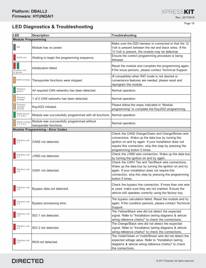
LED Description Troubleshooting
Module has no power.
Make sure the D2D harness is connected or that the 12
Volt is present between the red and black wires. If the
12 Volt is present, the module may be defective.
Waiting to begin the programming sequence.Ensure the correct programming procedure is being
followed.
Initialization failed.Reset the module and complete the programming again.
If the issue persists, please contact Technical Support.
Transponder functions were skipped.
(If compatible) when RXT mode is not desired or
convenience features are needed, please reset and
reprogram the module.
All required CAN networks has been detected. Normal operation.
1 of 2 CAN networks has been detected. Normal operation
Key2GO initiated.Please follow the steps indicated in “Module
programming” to complete the Key2GO programming.
Module was successfully programmed with all functions. Normal operation
Module was successfully programmed without
transponder functions.Normal operation.
CAN2 not detected.
Check the CAN2 Orange/Green and Orange/Brown wire
connections. Wake up the data bus by turning the
ignition on and try again. If your installation does not
require this connection, skip this step by pressing the
programming button 5 times.
J1850 not detected.Check the J1850 wire connection. Wake up the data bus
by turning the ignition on and try again.
CAN1 not detected.
Check the CAN1 Tan and Tan/Black wire connections.
Wake up the data bus by turning the ignition on and try
again. If your installation does not require this
connection, skip this step by pressing the programming
button 5 times.
Bypass data not detected.
Check the bypass line connection. If more than one wire
is used, make sure they are not inverted. Ensure the
vehicle still operates correctly using the factory key.
Bypass processing error.
The bypass calculation failed. Reset the module and try
again. If the condition persists, please contact Technical
Support.
ISO 1 not detected.
The Yellow/Black wire did not detect the expected
signal. Refer to "Installation (wiring diagrams & vehicle
wiring reference charts)" to check the connections.
ISO 2 not detected.
The Orange/Black wire did not detect the expected
signal. Refer to "Installation (wiring diagrams & vehicle
wiring reference charts)" to check the connections.
MUX not detected.
The Violet/Green or Violet/Brown wire did not detect the
expected voltage value. Refer to "Installation (wiring
diagrams & vehicle wiring reference charts)" to check
the connections.
Module Programming
Module Programming - Error Codes
Solid red
Flashes redx 1
Flashes redx 1
Flashes redx 2
Flashes redx 3
Flashes redx 4
Flashes redx 5
Flashes redx 6
Flashes redx 7
Solid greenx 3 secs
Flashesgreen
Solid orange
Flashes red& green
Off
Flashesorange
Flashesorangeslowly
Solid orangex 3 secs
Page 18
LED Diagnostics & Troubleshooting

Rev.: 20170818
Platform: DBALL2
Firmware: HYUNDAI1
© 2017 Directed. All rights reserved.
LED Description Troubleshooting
OBDII feature is not supported.The diagnostic data bus was not detected, therefore the
SmartStart features will be limited.
Ground When Running (Status) command received. The module has initialized the remote start sequence.
Ignition ON command received.The module has received the Ignition ON command and
is processing the remote start sequence.
Start ON command received.The module has received the Start ON command and is
processing the remote start sequence.
PTS shutdown error.The PTS output from the module was not activated due
to safety protection.
CAN bus incorrectly detected.
Verify the CAN1 and CAN2 connections. Refer to
“Installation (wiring diagrams & vehicle wiring reference
charts)” to check the connections.
LOCK command received.
UNLOCK command received.
TRUNK command received.
AUX1 command received.
AUX2 command received.
AUX3 command received.
Takeover successful. Normal operation.
Runsafe was not disabled.No UNLOCK command was received prior to opening the
door, or the 45 second timer expired in takeover mode.
Brake was not detected.The brakes were not detected, which prevents the
system from shutting down the vehicle.
Smart key was not detected.The smart key was not detected, which prevents the
system from shutting down the vehicle.
Speed was detected.The vehicle was detected as moving, which prevents the
system from shutting it down.
External module synchronization
Commands
Activation Ground When Running (Status)
If the bypass module fails to flash, it did not receive the
signal. Commands can come from RF or D2D.
Shutdown codes
(Flashes red,red thenorange) x 10
Flashes red& orange
Flashes redx 21
Flashes redx 2
Flashes redx 4
Flashes redx 10
Flashes redx 1
Flashes redx 3
Flashesgreen
Flashesgreenquickly
Flashesgreen x 1
Flashesorange x 1
Flashesorange x 2
Flashesorange x 3
Flashesorange x 5
Flashesorange x 4
Flashesorange x 6
Page 19

For a period of from the date of purchase of a Directed Electronics remote start or security product, DirectedONE YEARElectronics. (“ ”) promises to the original purchaser, to repair or replace with a comparable reconditioned piece, theDIRECTEDsecurity or remote start accessory piece (hereinafter the “Part”), which proves to be defective in workmanship or materialunder normal use, provided the following conditions are met: the Part was purchased from an authorized dealer;DIRECTEDand the Part is returned to , postage prepaid, along with a clear, legible copy of the receipt or bill of sale bearing theDIRECTEDfollowing information: consumer’s name, address, telephone number, the authorized licensed dealer’s name and completeproduct and Part description.
This warranty is nontransferable and is automatically void if the Part has been modified or used in a manner contrary to itsintended purpose or the Part has been damaged by accident, unreasonable use, neglect, improper service, installation orother causes not arising out of defect in materials or construction.
TO THE MAXIMUM EXTENT ALLOWED BY LAW EXCEPT AS STATED ABOVE ALL WARRANTIES INCLUDING, , ,BUT NOT LIMITED TO EXPRESS WARRANTY IMPLIED WARRANTY WARRANTY OF MERCHANTABILITY, , ,FITNESS FOR PARTICULAR PURPOSE AND WARRANTY OF NONINFRINGEMENT OF INTELLECTUALPROPERTY ARE EXPRESSLY EXCLUDED AND DIRECTED NEITHER ASSUMES NOR AUTHORIZES ANY, ;PERSON OR ENTITY TO ASSUME FOR IT ANY DUTY OBLIGATION OR LIABILITY IN CONNECTION WITH ITS,PRODUCTS DIRECTED HEREBY DISCLAIMS AND HAS ABSOLUTELY NO LIABILITY FOR ANY AND ALLACTS OF.THIRD PARTIES INCLUDING DEALERS OR INSTALLERS DIRECTED IS NOT OFFERING GUARANTEE OR. AINSURANCE AGAINST VANDALISM DAMAGE OR THEFT OF THE AUTOMOBILE ITS PARTS OR CONTENTS, , , ,AND DIRECTED HEREBY DISCLAIMS ANY LIABILITY WHATSOEVER INCLUDING WITHOUT LIMITATION, ,LIABILITY FOR THEFT DAMAGE OR VANDALISM IN THE EVENT OF CLAIM OR DISPUTE INVOLVING, , . A ADIRECTED OR ITS SUBSIDIARY THE PROPER VENUE SHALL BE SAN DIEGO COUNTY IN THE STATE OF,CALIFORNIA CALIFORNIA STATE LAWS AND APPLICABLE FEDERAL LAWS SHALL APPLY AND GOVERN THE.DISPUTE THE MAXIMUM RECOVERY UNDER ANY CLAIM AGAINST DIRECTED SHALL BE STRICTLY LIMITED.TO THE AUTHORIZED DIRECTED DEALER PURCHASE PRICE OF THE PART DIRECTED SHALL NOT BE’S .RESPONSIBLE FOR ANY DAMAGES WHATSOEVER INCLUDING BUT NOT LIMITED TO ANY CONSEQUENTIAL, ,DAMAGES INCIDENTAL DAMAGES DAMAGES FOR THE LOSS OF TIME LOSS OF EARNINGS COMMERCIAL, , , ,LOSS LOSS OF ECONOMIC OPPORTUNITY AND THE LIKE NOTWITHSTANDING THE ABOVE THE, . ,MANUFACTURER DOES OFFER LIMITED WARRANTY TO REPLACE OR REPAIR AT DIRECTED OPTION THEA ’SPARTAS DESCRIBED ABOVE.
This warranty only covers Parts sold within the United States ofAmerica and Canada. Parts sold outside of the United States ofAmerica or Canada are sold “ - ” and shall have , express or implied. Some states do not allow limitationsAS IS NO WARRANTYon how long an implied warranty will last or the exclusion or limitation of incidental or consequential damages. This warrantygives you specific legal rights and you may also have other rights that vary from State to State. does not and hasDIRECTEDnot authorized any person or entity to create for it any other obligation, promise, duty or obligation in connection with this Part.For further details relating to warranty information of Directed products, please visit the support section of ’sDIRECTEDwebsite at: www.directed.com
920-10012-01 2013-07
This Interface kit / Data Bus Interface part has been tested on the listed vehicles. Other vehicles will be added to the selectvehicle list upon completion of compatibility testing. Visit website for latest vehicle application guide. : Under noDISCLAIMERcircumstances shall the manufacturer or the distributors of the bypass kit / data bus interface part(s) be held liable for anyconsequential damages sustained in connection with the part(s) installation. The manufacturer and it’s distributors will not, norwill they authorize any representative or any other individual to assume obligation or liability in relation to the interface kit / databus interface part(s) other than its replacement. N.B.: Under no circumstances shall the manufacturer and distributors of thisproduct be liable for consequential damages sustained in connection with this product and neither assumes nor authorizesany representative or other person to assume for it any obligation or liability other than the replacement of this product only.
Protected by U.S. Patents: 5,719,551; 6,011,460 B1 *; 6,243,004 B1; 6,249,216 B1; 6,275,147 B1; 6,297,731 B1; 6,346,876B1; 6,392,534 B1; 6,529,124 B2; 6,696,927 B2; 6,756,885 B1; 6,756,886 B2; 6,771,167 B1; 6,812,829 B1; 6,924,750 B1;7,010,402 B1; 7,015,830 B1; 7,031,826 B1; 7,046,126 B1; 7,061,137 B1; 7,068,153 B1; 7,205,679 B1; Cdn. Patent:2,320,248; 2,414,991; 2,415,011; 2,415,023; 2,415,027; 2,415,038; 2,415,041; 2,420,947; 2,426,670; 2,454,089; EuropeanPatent: 1,053,128; Pat. Pending: 2,291,306. Made in Canada.
Limited Consumer WarrantyOne YearPage 20
Rev.: 20170818
Platform: DBALL2
Firmware: HYUNDAI1
© 2017 Directed. All rights reserved.

4
3
1 1
2
3
Press the remote start button on the transmitter to start the vehicle.*
Stop the vehicle in a safe parking spot and put the gear in Park (P).
2
Press the brake pedal, put the car in gear and drive off.
Enter the vehicle, while making sure the key is inside with you.**
Press the Unlock button on the aftermarket remote.*
Ready to drive off
Press remote start
button*
Press Unlock button*
Stop & put vehicle in Park (P)
P&
HOLD
Exit vehicle with Smart Key
Quick Reference GuideDBALL2-HYUNDAI1
© 2017 Directed. All rights reserved.
Press remote start
button*
Enter vehicle with Smart Key
HOLD
Pit Stop Mode
The Pit Stop Mode feature is practical when you need to stop and run an errand, but wish to keep the engine running.
Note: We recommend that you always lock the doors of your vehicle when leaving it unattended.
It is now safe to leave the engine running and exit the vehicle with the Smart Key in hand.
Press the button to remote start the vehicle.*
Vehicle Takeover with Get In and Go GG
* Your aftermarket remote may differ from the model shown in the illustrations.
* Your aftermarket remote may differ from the model shown in the illustrations.
** The vehicle will shutdown if the key is not in the vehicle.
Get In and Go
Get In and Go is designed to provide users with easy takeover when entering their Push-to-Start (PTS) equipped vehicle, once it has been remote started.
Typically, users would have to remote start their vehicle, then get inside and press the vehicle start button to perform a takeover. There is therefore a physical action required to drive away. With Get In and Go technology, you simply remote start the vehicle, unlock the doors, get in and go... Nothing to do but put the gear in drive and enjoy your vehicle.
This unique feature monitors a variety of parameters such as the key fob, vehicle speed sensor and door sensor, in order to perform takeover securily.
GG
Note: Takeover feature is not available on the Kia Optima. The engine will stopwhen a door is opened.

Quick Reference GuideDBALL2-HYUNDAI1
© 2017 Directed. All rights reserved.
Button(s) Actions
Press & hold for 1 second to lock.
Press & hold for 1 second to unlock.
Press & hold for 1 second to remote
start.
Press & hold for 5 seconds to activate
the trunk release (optional).
Press once, then to activate the
panic mode.
Press once, then to reset the
remote starter runtime.
List of Available Commands
x1 +
x1 +
Note that the information below is for Viper, Clifford and Python models. Icons and commands may differ depending on the remote brand and model purchased. Refer to your authorized installation center for more information.
Notes
Related Documents


