Plate Heat Exchangers for General Refinery Services API Standard 662, Second Edition April 2002 ISO 15547: 2000, Petroleum and Natural Gas Industries—Plate Heat Exchangers Copyright American Petroleum Institute Reproduced by IHS under license with API Document provided by IHS Licensee=Shell Services International B.V./5924979112, 11/04/2004 00:48:23 MST Questions or comments about this message: please call --``,,`,,,,`,,,````,,`,,,``,,-`-`,,`,,`,`,,`---

Welcome message from author
This document is posted to help you gain knowledge. Please leave a comment to let me know what you think about it! Share it to your friends and learn new things together.
Transcript

Plate Heat Exchangers for General Refinery Services
API Standard 662, Second EditionApril 2002
ISO 15547: 2000, Petroleum and Natural GasIndustries—Plate Heat Exchangers
Copyright American Petroleum Institute Reproduced by IHS under license with API
Document provided by IHS Licensee=Shell Services International B.V./5924979112, 11/04/2004 00:48:23 MST Questions or comments about this message: please callthe Document Policy Group at 303-397-2295.
--``,,`,,,,`,,,````,,`,,,``,,-`-`,,`,,`,`,,`---

American Petroleum Institute API Standard 662/ISO 15547:2000
i
SPECIAL NOTES
API publications necessarily address problems of a general nature. With respect to particular circumstances,local, state, and federal laws and regulations should be reviewed.
API is not undertaking to meet the duties of employers, manufacturers, or suppliers to warn and properlytrain and equip their employees, and others exposed, concerning health and safety risks and precautions,nor undertaking their obligations under local, state, or federal laws.
Information concerning safety and health risks and proper precautions with respect to particular materialsand conditions should be obtained from the employer, the manufacturer or supplier of that material, or thematerial safety data sheet.
Nothing contained in any API publication is to be construed as granting any right, by implication orotherwise, for the manufacture, sale, or use of any method, apparatus, or product covered by letters patent.Neither should anything contained in the publication be construed as insuring anyone against liability forinfringement of letters patent.
Generally, API standards are reviewed and revised, reaffirmed, or withdrawn at least every five years.Sometimes a one-time extension of up to two years will be added to this review cycle. This publication willno longer be in effect five years after its publication date as an operative API standard or, where anextension has been granted, upon republication. Status of the publication can be ascertained from the APIStandards Department [telephone (202) 682-8000]. A catalog of API publications and materials is publishedannually and updated quarterly by API, 1220 L Street, N.W., Washington, D.C. 20005.
This document was produced under API standardization procedures that ensure appropriate notification andparticipation in the developmental process and is designated as an API standard. Questions concerning theinterpretation of the content of this standard or comments and questions concerning the procedures underwhich this standard was developed should be directed in writing to the director/general manager of theStandards Department, American Petroleum Institute, 1220 L Street, N.W., Washington, D.C. 20005.Requests for permission to reproduce or translate all or any part of the material published herein should alsobe addressed to the director.
API standards are published to facilitate the broad availability of proven, sound engineering and operatingpractices. These standards are not intended to obviate the need for applying sound engineering judgmentregarding when and where these standards should be utilized. The formulation and publication of APIstandards is not intended in any way to inhibit anyone from using any other practices.
Any manufacturer marking equipment or materials in conformance with the marking requirements of an APIstandard is solely responsible for complying with all the applicable requirements of that standard. API doesnot represent, warrant, or guarantee that such products do in fact conform to the applicable API standard.
Copyright American Petroleum Institute Reproduced by IHS under license with API
Document provided by IHS Licensee=Shell Services International B.V./5924979112, 11/04/2004 00:48:23 MST Questions or comments about this message: please callthe Document Policy Group at 303-397-2295.
--``,,`,,,,`,,,````,,`,,,``,,-`-`,,`,,`,`,,`---

API Standard 662/ISO 15547:2000 American Petroleum Institute
ii
API FOREWORD
This standard is under the jurisdiction of the API Committee on Refinery Equipment, Subcommittee on HeatTransfer Equipment. This API standard is identical with the English version of ISO 15547. ISO 15547 wasprepared by Technical Committee ISO/TC TCÊ67, Materials, equipment and offshore structures for petroleum and
natural gas industries, Subcommittee SC 6, Processing equipment and systems.
This standard shall become effective on the date printed on the cover but may be used voluntarily from thedate of distribution.
API publications may be used by anyone desiring to do so. Every effort has been made by the Institute toassure the accuracy and reliability of the data contained in them; however, the Institute makes norepresentation, warranty, or guarantee in connection with this publication and hereby expressly disclaimsany liability or responsibility for loss or damage resulting from its use or for the violation of any federal, state,or municipal regulation with which this publication may conflict.
Suggested revisions are invited and should be submitted to Standards Department, API, 1220 L Street, NW,Washington, DC 20005.
Copyright American Petroleum Institute Reproduced by IHS under license with API
Document provided by IHS Licensee=Shell Services International B.V./5924979112, 11/04/2004 00:48:23 MST Questions or comments about this message: please callthe Document Policy Group at 303-397-2295.
--``,,`,,,,`,,,````,,`,,,``,,-`-`,,`,,`,`,,`---

American Petroleum Institute API Standard 662/ISO 15547:2000
iii
ISO FOREWORD
ISO (the International Organization for Standardization) is a worldwide federation of national standards bodies (ISOmember bodies). The work of preparing International Standards is normally carried out through ISO technicalcommittees. Each member body interested in a subject for which a technical committee has been established has theright to be represented on that committee. International organizations, governmental and non-governmental, in liaisonwith ISO, also take part in the work. ISO collaborates closely with the International Electrotechnical Commission (IEC)on all matters of electrotechnical standardization.
International Standards are drafted in accordance with the rules given in the ISO/IEC Directives, PartÊ3.
Draft International Standards adopted by the technical committees are circulated to the member bodies for voting.Publication as an International Standard requires approval by at least 75Ê% of the member bodies casting a vote.
Attention is drawn to the possibility that some of the elements of this International Standard may be the subject ofpatent rights. ISO shall not be held responsible for identifying any or all such patent rights.
International Standard ISOÊ15547 was prepared by Technical Committee ISO/TCÊ67, Materials, equipment andoffshore structures for petroleum and natural gas industries, Subcommittee SCÊ6, Processing equipment and systems.
Annexes A, B and C of this Standard are for information only.
Copyright American Petroleum Institute Reproduced by IHS under license with API
Document provided by IHS Licensee=Shell Services International B.V./5924979112, 11/04/2004 00:48:23 MST Questions or comments about this message: please callthe Document Policy Group at 303-397-2295.
--``,,`,,,,`,,,````,,`,,,``,,-`-`,,`,,`,`,,`---

API Standard 662/ISO 15547:2000 American Petroleum Institute
iv
Contents Page
API Foreword ...................................................................................................................................................................... ii
ISO Foreword..................................................................................................................................................................... iii
Introduction.........................................................................................................................................................................v
1 Scope .....................................................................................................................................................................1
2 Normative references...........................................................................................................................................1
3 Terms, definitions and abbreviated terms........................................................................................................13.1 Terms and definitions..........................................................................................................................................13.2 Abbreviated terms................................................................................................................................................4
4 General...................................................................................................................................................................4
5 Conflicting requirements.....................................................................................................................................4
6 Proposal information required ...........................................................................................................................4
7 Drawings and other data requirements ............................................................................................................57.1 Drawings................................................................................................................................................................57.2 Final records .........................................................................................................................................................6
8 Design ....................................................................................................................................................................68.1 General...................................................................................................................................................................68.2 Design temperature..............................................................................................................................................68.3 Design pressure ...................................................................................................................................................68.4 Fouling margin......................................................................................................................................................68.5 Corrosion allowance............................................................................................................................................68.6 Components..........................................................................................................................................................78.7 Connections ..........................................................................................................................................................88.8 Plate gaskets.......................................................................................................................................................118.9 Handling devices................................................................................................................................................12
9 Materials ..............................................................................................................................................................12
10 Fabrication...........................................................................................................................................................1310.1 Welding ................................................................................................................................................................1310.2 Plate gasket installation ....................................................................................................................................1310.3 Surface finish......................................................................................................................................................1310.4 Assembly .............................................................................................................................................................13
11 Inspection and testing .......................................................................................................................................1311.1 Quality control ....................................................................................................................................................1311.2 Hydrostatic testing.............................................................................................................................................1311.3 Nameplates and stampings ..............................................................................................................................14
12 Preparation for shipment ..................................................................................................................................14
Annex A (informative) Recommended practice ...........................................................................................................15
Annex B (informative) Plate heat exchanger checklist ...............................................................................................18
Annex C (informative) Plate heat exchanger data sheets ..........................................................................................19
Bibliography .....................................................................................................................................................................26
Copyright American Petroleum Institute Reproduced by IHS under license with API
Document provided by IHS Licensee=Shell Services International B.V./5924979112, 11/04/2004 00:48:23 MST Questions or comments about this message: please callthe Document Policy Group at 303-397-2295.
--``,,`,,,,`,,,````,,`,,,``,,-`-`,,`,,`,`,,`---
American Petroleum Institute API Standard 662/ISO 15547:2000
v
Introduction
This International Standard is based on API standard 662, December 1995 edition.
Users of this International Standard should be aware that further or differing requirements may be needed for individualapplications. This International Standard is not intended to inhibit a vendor from offering, or the purchaser fromaccepting, alternative equipment or engineering solutions for the individual application. This may be particularlyapplicable where there is an innovative or developing technology. Where an alternative is offered, the vendor shouldidentify any variations from this International Standard and provide details.
This International Standard requires the purchaser to specify certain details and features.
A round bullet (l) at the beginning of a clause or subclause indicates that either a decision is required or furtherinformation is to be provided by the purchaser. This information should be indicated on the plate heat exchangerchecklist (see annexÊB).
A triangular bullet (s) at the beginning of a clause or subclause indicates an item appearing on the plate heatexchanger data sheet (see annexÊC).
Copyright American Petroleum Institute Reproduced by IHS under license with API
Document provided by IHS Licensee=Shell Services International B.V./5924979112, 11/04/2004 00:48:23 MST Questions or comments about this message: please callthe Document Policy Group at 303-397-2295.
--``,,`,,,,`,,,````,,`,,,``,,-`-`,,`,,`,`,,`---

American Petroleum Institute
1
Petroleum and natural gas industriesÊÑ Plate heatexchangers
1 Scope
This International Standard gives requirements and recommendations for the mechanical design, materialsselection, fabrication, inspection, testing, and preparation for shipment of plate heat exchangers, sometimesreferred to as plate-and-frame heat exchangers, for use in petroleum and natural gas industries.
This International Standard covers gasketed, semi-welded and welded plate heat exchangers constrained within aframe.
As used in this International Standard, the term heat exchangers, or exchangers, includes coolers, heaters,condensers, evaporators and reboilers.
2 Normative reference
The following normative document contains provisions which, through reference in this text, constitute provisions ofthis International Standard. For dated references, subsequent amendments to, or revisions of, any of thesepublications do not apply. However, parties to agreements based on this International Standard are encouraged toinvestigate the possibility of applying the most recent edition of the normative document indicated below. Forundated references, the latest edition of the normative document referred to applies. Members of ISO and IECmaintain registers of currently valid International Standards.
ISOÊ8501-1, Preparation of steel substrates before application of paints and related products Ñ Visual assessmentof surface cleanliness Ñ PartÊ1: Rust grades and preparation grades of uncoated steel substrates and of steelsubstrates after overall removal of previous coatings.
3 Terms, definitions and abbreviated terms
3.1 Terms and definitions
For the purposes of this International Standard, the following terms and definitions apply.
3.1.1connector plateplate used to separate two or more services in one plate heat exchanger
3.1.2drip traytray that is able to collect droplets from an entire heat exchanger plate pack
3.1.3end platestwo plates, one at each end, that prevent the fluids in a plate heat exchanger from contacting the frame
Copyright American Petroleum Institute Reproduced by IHS under license with API
Document provided by IHS Licensee=Shell Services International B.V./5924979112, 11/04/2004 00:48:23 MST Questions or comments about this message: please callthe Document Policy Group at 303-397-2295.
--``,,`,,,,`,,,````,,`,,,``,,-`-`,,`,,`,`,,`---

API Standard 662/ISO 15547:2000 American Petroleum Institute
2
3.1.4exchanger serviceone or more plate heat exchangers for a total specified heat-transfer duty
3.1.5frameassembly that provides the structural support and pressure containment of a plate heat exchanger
3.1.6fully welded plate packplate pack where all the gaskets have been replaced by welds
3.1.7heat transfer areasum of the surface areas of one side of all plates in contact with both heat-transfer fluids
NOTE Areas of end plates are not included.
3.1.8item numberpurchaserÕs identification number for a plate heat exchanger
3.1.9nominal plate gapforming depth of an individual plate
3.1.10pass plateplate used to change the direction of flow of a stream in a multi-pass plate heat exchanger
3.1.11platesheet of material precision-pressed or -formed into a corrugated pattern
3.1.12plate chevron angleangle formed between the corrugated plate pattern and the horizontal
3.1.13plate heat exchangerPHEassembly of a gasketed, semi-welded or welded plate pack and its supporting frame
NOTE Figure 1 shows typical components of a plate heat exchanger.
3.1.14plate packgrouping of all plates contained within a frame
3.1.15portinlet or outlet opening in the plate
3.1.16pressure design coderecognized pressure vessel standard specified or agreed by the purchaser
EXAMPLE ASME VIII.
Copyright American Petroleum Institute Reproduced by IHS under license with API
Document provided by IHS Licensee=Shell Services International B.V./5924979112, 11/04/2004 00:48:23 MST Questions or comments about this message: please callthe Document Policy Group at 303-397-2295.
--``,,`,,,,`,,,````,,`,,,``,,-`-`,,`,,`,`,,`---

American Petroleum Institute API Standard 662/ISO 15547:2000
3
3.1.17semi-welded plate pairtwo adjacent plates welded together where the weld replaces the function of a gasket
3.1.18shroudremovable covering for the top and sides of the plate pack of the plate heat exchanger, which provides protectionin the event of a spray leak or fire
3.1.19structural welding coderecognized structural welding code specified or agreed by the purchaser
EXAMPLE AWS D1.1 for steel.
Key
1 Mounting feet 6 Tie bolts
2 Plate pack 7 Guide bar (bottom)
3 Fixed cover 8 Carrying bar (top)
4 Movable cover 9 Connections, studded or flanged
5 Support column 10 Tie nuts
FigureÊ1ÊÑ Typical single-pass plate heat exchanger
Copyright American Petroleum Institute Reproduced by IHS under license with API
Document provided by IHS Licensee=Shell Services International B.V./5924979112, 11/04/2004 00:48:23 MST Questions or comments about this message: please callthe Document Policy Group at 303-397-2295.
--``,,`,,,,`,,,````,,`,,,``,,-`-`,,`,,`,`,,`---

API Standard 662/ISO 15547:2000 American Petroleum Institute
4
3.2 Abbreviated terms
ASME American Society of Mechanical Engineers
AWS American Welding Society
IRHD International rubber hardness degree
MDMT Minimum design metal temperature
MRB Manufacturing record book
NDE Non-destructive examination
PHE Plate heat exchanger
4 General
l▲ 4.1 The pressure design code shall be specified or agreed by the purchaser. Pressure components shall complywith the pressure design code and the supplemental requirements in this International Standard.
The structural welding code shall be specified or agreed by the purchaser.
AnnexÊA provides some recommended mechanical and design details for information. AnnexÊA also includes someprecautions for consideration when specifying fouling margin, fireproof shrouds and plate gaskets.
l▲ 4.2 The vendor shall comply with the applicable local regulations specified by the purchaser.
l▲ 4.3 If specified by the purchaser, or if required by national, state or local codes, the vendor shall register eachexchanger.
In this International Standard, where practical, US Customary units are included in parentheses for information.
5 Conflicting requirements
The vendor shall obtain written approval from the purchaser before proceeding with work affected by a conflictbetween the proposal and the purchase order.
6 Proposal information required
6.1 The vendor shall complete all information requested on the data sheet.
6.2 For components that are not fully identified by the terms and definitions in 3.1 of this International Standard,the vendor shall describe the details of construction and assembly.
6.3 The vendor shall include a detailed description of any exception to the specified requirements.
6.4 The first-time use of a PHE design, component or material by the vendor for the purchaserÕs intendedservice shall be clearly indicated by the vendor.
6.5 The vendor shall state anticipated life in the specified service and in storage of the gaskets proposed.Special requirements for gasket storage to maintain gasket shelf-life shall be specified.
6.6 The vendor shall state the method of support used for the movable cover.
Copyright American Petroleum Institute Reproduced by IHS under license with API
Document provided by IHS Licensee=Shell Services International B.V./5924979112, 11/04/2004 00:48:23 MST Questions or comments about this message: please callthe Document Policy Group at 303-397-2295.
--``,,`,,,,`,,,````,,`,,,``,,-`-`,,`,,`,`,,`---

American Petroleum Institute API Standard 662/ISO 15547:2000
5
6.7 The vendor shall supply a recommended spare parts list and unit spare-part prices for each plate heatexchanger.
6.8 The vendor shall state recommended plate-cleaning method(s).
▲ 6.9 If a fireproof shroud is specified, the PHE vendor shall submit proof that the proposed design has passedsuitable type testing.
7 Drawings and other data requirements
7.1 Drawings
7.1.1 The vendor shall submit general configuration drawings for each PHE for review. The drawings shallinclude the following information:
a) service, item number, project name and location, vendorÕs shop order number and purchaserÕs order number;
b) maximum allowable working pressure, design pressure, test pressure, design temperature, minimum designmetal temperature and any restrictions regarding testing or operation of the PHE;
c) dimensions and location of supports;
d) overall exchanger dimensions;
e) maximum and minimum compressed plate pack length;
f) side clearance required for plate removal;
g) mass of the PHE, both empty and full of water;
h) centre of gravity of the exchanger for empty and operating conditions;
i) corrosion allowance;
j) material specifications for all components;
k) allowable forces and moments on connections;
l) size, flange rating and facing, location, orientation, and flow identification of all connections;
m) applicable design codes;
n) number of plates installed and maximum number of plates for specified frame;
o) gasket materials and adhesives required.
7.1.2 The vendor shall recommend the tools needed for the assembly and maintenance of the PHE. If torquingof bolts is required, the vendor shall provide torquing procedures.
7.1.3 The review of general configuration drawings by the purchaser shall not relieve the vendor of theresponsibility of meeting the requirements of the purchase order.
7.1.4 After receipt of the purchaserÕs general configuration drawing review comments, the vendor shall furnishthe certified general configuration drawings and the detail drawings.
l 7.1.5 If specified by the purchaser, the vendor shall furnish copies of applicable welding procedure specificationsand weld maps for review or record.
l 7.1.6 If specified by the purchaser, the vendor shall furnish copies of applicable calculations for review or record.
Copyright American Petroleum Institute Reproduced by IHS under license with API
Document provided by IHS Licensee=Shell Services International B.V./5924979112, 11/04/2004 00:48:23 MST Questions or comments about this message: please callthe Document Policy Group at 303-397-2295.
--``,,`,,,,`,,,````,,`,,,``,,-`-`,,`,,`,`,,`---

API Standard 662/ISO 15547:2000 American Petroleum Institute
6
7.2 Final records
7.2.1 The vendor shall furnish the purchaser with a user's manual which shall contain the following:
a) technical description,
b) assembly instructions,
c) operating instructions,
d) maintenance instructions,
e) spare parts list,
f) data sheets and drawings (as-built).
7.2.2 The vendor shall maintain records to confirm compliance of the material and fabrication with therequirements of this International Standard for at least five years.
8 Design
8.1 General
8.1.1 The frame and tie bolts of the gasketed or semi-welded PHE shall be designed to permit future installationof a minimum of 20Ê% additional plates.
8.1.2 Gasketed plates shall be replaceable individually, and semi-welded plates in pairs, without having toremove any other plate.
8.1.3 The plate pack shall incorporate means for positive alignment of the plates and gaskets.
8.2 Design temperature
▲ 8.2.1 All PHEs shall have two design temperatures, a maximum design temperature and a minimum designmetal temperature (MDMT), specified by the purchaser.
8.2.2 The design temperatures shall be used for the design of all pressure-retaining components.
8.3 Design pressure
The plate heat exchanger design shall not be based on differential pressure.
8.4 Fouling margin
l The purchaser shall specify a percentage fouling margin where:
Fouling margin = (Uclean/Uservice Ð 1) × 100 (1)
where
U is the thermal transmittance (overall heat transfer coefficient).
8.5 Corrosion allowance
▲ 8.5.1 Corrosion allowance, if specified, shall apply to connections only.
8.5.2 Plate material shall be selected based on an assumed zero corrosion allowance.
Copyright American Petroleum Institute Reproduced by IHS under license with API
Document provided by IHS Licensee=Shell Services International B.V./5924979112, 11/04/2004 00:48:23 MST Questions or comments about this message: please callthe Document Policy Group at 303-397-2295.
--``,,`,,,,`,,,````,,`,,,``,,-`-`,,`,,`,`,,`---

American Petroleum Institute API Standard 662/ISO 15547:2000
7
8.6 Components
8.6.1 Plates shall conform to the following.
a) The nominal thickness of gasketed plates before being pressed shall be sufficient to meet design conditionsbut shall not be less than 0,5Êmm (0,02Êinch).
b) The plates shall be fully supported by the carrying bar.
c) The plates shall be designed to meet the design conditions without the need of additional stiffeners attached tothe plate, unless otherwise approved by the purchaser.
d) The thickness of pass plates shall be sufficient to withstand the total stream pressure drop across the portarea.
e) The wetted areas of fabricated pass support plates shall be constructed of similar material to the plates.
f) All gasketed and semi-welded plates shall have permanently stamped identification for proper assembly.
g) End plates shall be furnished at the fixed and movable covers.
8.6.2 Fixed and movable covers shall conform to the following.
a) Covers designed with the use of stiffeners shall require approval of the purchaser.
b) Covers shall be furnished with slotted holes for tie bolts. The design shall mechanically restrain the tie bolts ornuts from turning.
8.6.3 Tie bolts and nuts for gasketed and semi-welded plate packs shall conform to the following.
a) Tie bolts shall not be less than 16Êmm (5/8Êinch) nominal diameter, in accordance with the pressure designcode.
b) Each tie bolt shall have one captive nut and at least one running nut. The length of each nut shall be equal toor greater than a heavy hexagonal type, in accordance with the pressure design code.
c) Hardened steel washers shall be provided under all rotating nuts.
d) Each tie bolt shall be supplied greased and with a plastic sleeve to protect it from the environment.
8.6.4 The carrying bar for gasketed and semi-welded PHEs shall conform to the following.
a) The bearing surface shall permit easy sliding of the plates and movable cover along the entire length of thecarrying bar.
b) The carrying bar shall be designed to support at least 1,5Êtimes the total mass of the movable cover and platepack with the maximum number of plates filled with water (or the process fluid if its density is greater than thatof water).
▲ 8.6.5 Gasketed and semi-welded PHEs shall have a support column with a mounting foot located at the movablecover end. A minimum of two mounting feet shall be provided at the fixed cover. The supplier shall design thesupports for the external loads specified in the equipment data sheet or requisition documents.
l 8.6.6 If specified by the purchaser, the supplier shall provide details of the reaction at the support points.
l 8.6.7 If specified by the purchaser, PHEs shall be equipped with a shroud to protect against spray leaks.
l▲ 8.6.8 If specified by the purchaser, a suitable fire protection shroud shall be provided. The level of protectionshall be specified by the purchaser. For further information seeÊA.6.
Copyright American Petroleum Institute Reproduced by IHS under license with API
Document provided by IHS Licensee=Shell Services International B.V./5924979112, 11/04/2004 00:48:23 MST Questions or comments about this message: please callthe Document Policy Group at 303-397-2295.
--``,,`,,,,`,,,````,,`,,,``,,-`-`,,`,,`,`,,`---

API Standard 662/ISO 15547:2000 American Petroleum Institute
8
l▲ 8.6.9 If specified by the purchaser, PHEs shall be equipped with a drip tray.
8.6.10 All units shall have two earthing lugs, one connected at each end of the frame.
8.7 Connections
▲ 8.7.1 Connections shall be bolted and shall be of either studded or flanged design.
▲ 8.7.2 The use of studded and/or flanged connections and facings shall be specified on the data sheet.
8.7.3 Drilled and tapped holes for studded connection bolts shall not pass completely through the cover plate.The hole shall be threaded for a minimum length of one times the stud diameter.
8.7.4 The plate heat exchanger shall be self-draining and self-venting through the connections for all passarrangements.
8.7.5 For alloy-lined connections, the minimum thickness of the lining shall not be less than the plate thickness.
8.7.6 The projection of flanged connections shall be of sufficient length to allow installation and removal of theflange bolts from either side of the flange.
8.7.7 All bolt holes for flanged or studded connections shall straddle centrelines.
8.7.8 Connection sizes of DNÊ32 (NPSÊ1-1/4), DNÊ65 (NPSÊ2-1/2), DNÊ90 (NPSÊ3-1/2) or DNÊ125 (NPSÊ5) shallnot be used.
l 8.7.9 For alloy nozzles, the purchaser shall define requirements for either solid or lined connections, includingany connections fitted into the nozzle necks.
▲ 8.7.10 Connections shall be designed to withstand suitable loads and moments induced by the piping. TablesÊ1and 2 indicate a suitable initial estimate of loadings for connections either in standard or severe service. Unlessspecified by the purchaser, Standard Nozzle Loadings as shown in TableÊ1 shall be used. Directions of forces andmoments shall be as shown in FigureÊ2.
Copyright American Petroleum Institute Reproduced by IHS under license with API
Document provided by IHS Licensee=Shell Services International B.V./5924979112, 11/04/2004 00:48:23 MST Questions or comments about this message: please callthe Document Policy Group at 303-397-2295.
--``,,`,,,,`,,,````,,`,,,``,,-`-`,,`,,`,`,,`---

American Petroleum Institute API Standard 662/ISO 15547:2000
9
TableÊ1ÊÑ Standard-service nozzle loading
Nom. sizePNÊ20
(ASME rating 150)PNÊ50
(ASME rating 300)PNÊ110
(ASME rating 600)
DN F M F M F M
mm (in) N (lb) N⋅m (lb⋅ft) N (lb) N⋅m (lb⋅ft) N (lb) N⋅m (lb⋅ft)
25 (1) 90 (20) 0 (0) 119 (27) 1 (1) 167 (37) 2 (2)
40 (1,5) 159 (36) 37 (27) 209 (47) 40 (29) 293 (66) 44 (32)
50 (2) 208 (47) 76 (56) 273 (61) 80 (59) 383 (86) 88 (65)
80 (3) 365 (82) 230 (169) 480 (108) 246 (181) 673 (151) 274 (202)
100 (4) 477 (107) 358 (264) 628 (141) 388 (286) 879 (198) 438 (323)
150 (6) 776 (175) 750 (553) 1 022 (230) 840 (620) 1 430 (322) 990 (730)
200 (8) 1 096 (246) 1 236 (911) 1 443 (324) 1 431 (1 056) 2 020 (454) 1 758 (1 297)
250 (10) 1 433 (322) 1 809 (1 335) 1 886 (424) 2 167 (1 598) 2 640 (593) 2 763 (2 038)
300 (12) 1 784 (401) 2 471 (1 822) 2 347 (528) 3 056 (2 254) 3 286 (739) 4 032 (2 974)
350 (14) 2 146 (482) 3 220 (2 375) 2 824 (635) 4 108 (3 030) 3 953 (889) 5 587 (4 121)
400 (16) 2 519 (566) 4 060 (2 995) 3 314 (745) 5 333 (3 933) 4 640 (1 043) 7 454 (5 498)
450 (18) 2 901 (652) 4 993 (3 683) 3 818 (858) 6 742 (4 973) 5 345 (1 202) 9 658 (7 123)
500 (20) 3 292 (740) 6 021 (4 441) 4 332 (974) 8 346 (6 156) 6 065 (1 363) 12 221 (9 014)
NOTE The data above are based on the following equations:
F = (7,5 DN1,2
+ 0,1 PN ¥ DN1,2
) 5
M = [4(DN Ð 25)1,4
+ (2 x 10⁻⁵
) PN ¥ DN2,7
] 5
where
F = Fx = Fy = FzM = Mx = My = Mz
Copyright American Petroleum Institute Reproduced by IHS under license with API
Document provided by IHS Licensee=Shell Services International B.V./5924979112, 11/04/2004 00:48:23 MST Questions or comments about this message: please callthe Document Policy Group at 303-397-2295.
--``,,`,,,,`,,,````,,`,,,``,,-`-`,,`,,`,`,,`---

API Standard 662/ISO 15547:2000 American Petroleum Institute
10
TableÊ2ÊÑ Severe-service nozzle loading
Nom. sizePNÊ20
(ASME rating 150)PNÊ50
(ASME rating 300)PNÊ110
(ASME rating 600)
DN F M F M F M
mm (in) N (lb) N⋅m (lb⋅ft) N (lb) N⋅m (lb⋅ft) N (lb) N⋅m (lb⋅ft)
25 (1) 452 (102) 2 (2) 595 (134) 6 (4) 833 (187) 12 (9)
40 (1,5) 795 (179) 186 (137) 1 046 (235) 198 (146) 1 464 (329) 220 (162)
50 (2) 1 039 (234) 378 (279) 1 367 (307) 401 (296) 1 913 (430) 440 (324)
80 (3) 1 826 (410) 1 148 (847) 2 402 (540) 1 230 (907) 3 363 (756) 1 368 (1 009)
100 (4) 2 386 (536) 1 788 (1 318) 3 140 (706) 1 938 (1 430) 4 396 (988) 2 189 (1 615)
150 (6) 3 882 (873) 3 750 (2 766) 5 108 (1 148) 4 200 (3 098) 7 151 (1 608) 4 951 (3 651)
200 (8) 5 482 (1 232) 6 178 (4 556) 7 213 (1 622) 7 157 (5 279) 10 099 (2 270) 8 789 (6 483)
250 (10) 7 166 (1 611) 9 047 (6 673) 9 428 (2 120) 10 836 (7 992) 13 200 (2 967) 13 817 (10 191)
300 (12) 8 918 (2 005) 12 353 (9 111) 11 734 (2 638) 15 280 (11 270) 16 428 (3 693) 20 158 (14 868)
350 (14) 10 730 (2 412) 16 101 (11 876) 14 119 (3 174) 20 539 (15 149) 19 766 (4 444) 27 935 (20 604)
400 (16) 12 595 (2 831) 20 301 (14 973) 16 572 (3 726) 26 665 (19 667) 23 201 (5 216) 37 271 (27 490)
450 (18) 14 507 (3 261) 24 965 (18 413) 19 088 (4 291) 33 711 (24 864) 26 723 (6 008) 48 288 (35 616)
500 (20) 16 462 (3 701) 30 107 (22 206) 21 661 (4 870) 41 732 (30 780) 30 325 (6 817) 61 106 (45 069)
NOTE The data above are based on the following equations:
F = 7,5 DN1,2
+ 0,1 PN ¥ DN1,2
M = [4(DN Ð 25)1,4
+ (2 x 10⁻⁵
) PN ¥ DN2,7
]
where
F = Fx = Fy = FzM = Mx = My = Mz
Copyright American Petroleum Institute Reproduced by IHS under license with API
Document provided by IHS Licensee=Shell Services International B.V./5924979112, 11/04/2004 00:48:23 MST Questions or comments about this message: please callthe Document Policy Group at 303-397-2295.
--``,,`,,,,`,,,````,,`,,,``,,-`-`,,`,,`,`,,`---

American Petroleum Institute API Standard 662/ISO 15547:2000
11
FigureÊ2ÊÑ Directions of forces on connections
8.8 Plate gaskets
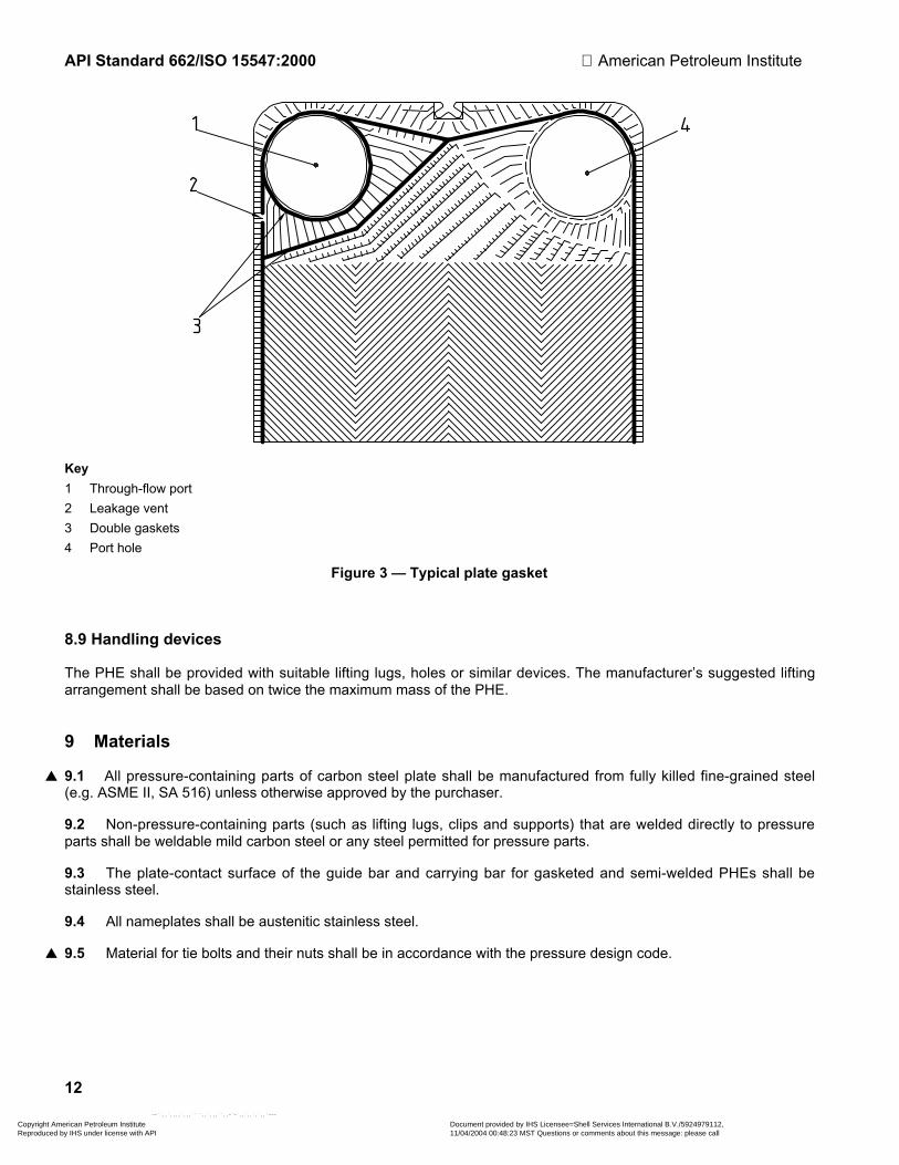
8.8.1 Gaskets shall be positioned in a groove around the heat transfer surface and around the port holes of theplate as indicated in FigureÊ3. Gaskets shall be secured to the plate by glue or by mechanical means.
8.8.2 Gaskets shall be compressed to achieve metal contact between plates.
8.8.3 Each sealing gasket shall be one integral piece.
8.8.4 Through-flow port areas of the plates shall be double-gasketed and vented to the atmosphere in such amanner that cross-contamination of fluids cannot occur without readily detectable external evidence.
8.8.5 The vendor shall verify the compatibility of the gasket material and glue with the specified fluids, includingany specified for chemical cleaning. For further information see A.8.
Copyright American Petroleum Institute Reproduced by IHS under license with API
Document provided by IHS Licensee=Shell Services International B.V./5924979112, 11/04/2004 00:48:23 MST Questions or comments about this message: please callthe Document Policy Group at 303-397-2295.
--``,,`,,,,`,,,````,,`,,,``,,-`-`,,`,,`,`,,`---
API Standard 662/ISO 15547:2000 American Petroleum Institute
12
Key
1 Through-flow port
2 Leakage vent
3 Double gaskets
4 Port hole
FigureÊ3ÊÑ Typical plate gasket
8.9 Handling devices
The PHE shall be provided with suitable lifting lugs, holes or similar devices. The manufacturerÕs suggested liftingarrangement shall be based on twice the maximum mass of the PHE.
9 Materials
▲ 9.1 All pressure-containing parts of carbon steel plate shall be manufactured from fully killed fine-grained steel(e.g. ASMEÊII, SAÊ516) unless otherwise approved by the purchaser.
9.2 Non-pressure-containing parts (such as lifting lugs, clips and supports) that are welded directly to pressureparts shall be weldable mild carbon steel or any steel permitted for pressure parts.
9.3 The plate-contact surface of the guide bar and carrying bar for gasketed and semi-welded PHEs shall bestainless steel.
9.4 All nameplates shall be austenitic stainless steel.
▲ 9.5 Material for tie bolts and their nuts shall be in accordance with the pressure design code.
Copyright American Petroleum Institute Reproduced by IHS under license with API
Document provided by IHS Licensee=Shell Services International B.V./5924979112, 11/04/2004 00:48:23 MST Questions or comments about this message: please callthe Document Policy Group at 303-397-2295.
--``,,`,,,,`,,,````,,`,,,``,,-`-`,,`,,`,`,,`---

American Petroleum Institute API Standard 662/ISO 15547:2000
13
10 Fabrication
10.1 Welding
▲ All pressure-containing welding shall be in accordance with the pressure design code, and structural welding shallbe in accordance with the structural welding code, unless otherwise specified by the purchaser.
10.2 Plate gasket installation
10.2.1 Gasket plate surfaces shall be thoroughly cleaned and dried with solvent or detergent solution, beforegasketing.
10.2.2 All gaskets shall be checked for adhesion and deformation after curing. All deformed or loose gaskets shallbe replaced and cured again.
10.3 Surface finish
10.3.1 Surfaces to be painted shall be degreased and cleaned by wire brushing or a similar means to removeloose scale, dirt and other foreign materials.
▲ 10.3.2 Unless otherwise specified, carbon steel covers shall be blast-cleaned in accordance with ISOÊ8501-1,gradeÊSaÊ2Ê1/2, and then coated with an inorganic zinc-rich primer to a dry-film thickness of at least 50ʵm (2Êmils).
10.4 Assembly
Each component shall be clearly and permanently identified for proper assembly in accordance with the detailedassembly instructions.
11 Inspection and testing
11.1 Quality control
l 11.1.1 Vendor shall supply information on its quality control system and a quality control plan upon purchaserÕsrequest.
l 11.1.2 Any requirement and extent of non-destructive testing of the heat transfer plates in addition to hydrostatictesting, such as a light box, liquid penetrant testing, helium leakage testing or equivalent, shall be specified by thepurchaser.
l 11.1.3 Where set-on connections are used on covers fabricated from plate, the purchaser should specify themethod of non-destructive testing to be used to detect laminations in the edge zone of the hole cut in the coverplate.
11.2 Hydrostatic testing
11.2.1 The hydrostatic test shall be separately applied to the hot side and to the cold side with no pressure to theother side.
11.2.2 The hydrostatic test pressure for each test shall be held for a sufficient time to permit a thorough inspectionand detection of small seepage leaks, or for not less than 30Êmin. After completion of the test, the PHE shall bedrained.
11.2.3 For each hydrostatic test, two indicating gauges (or one indicating gauge and one recording gauge) shallbe attached to the PHE.
Copyright American Petroleum Institute Reproduced by IHS under license with API
Document provided by IHS Licensee=Shell Services International B.V./5924979112, 11/04/2004 00:48:23 MST Questions or comments about this message: please callthe Document Policy Group at 303-397-2295.
--``,,`,,,,`,,,````,,`,,,``,,-`-`,,`,,`,`,,`---

API Standard 662/ISO 15547:2000 American Petroleum Institute
14
11.2.4 The minimum water temperature for hydrostatic testing shall be 17Ê°C (30Ê°F) above MDMT to avoid risk ofbrittle fracture, but shall not exceed 49Ê°C (120Ê°F).
11.2.5 The chloride content of water used for hydrostatic testing of pressure parts of solid austenitic stainlesssteel materials or austenitic stainless steel-lined parts shall not exceed 30Êmg/kg (30Êppm by mass).
11.3 Nameplates and stampings
11.3.1 A nameplate shall be permanently attached to the PHE.
11.3.2 Standard nameplate data shall include:
a) manufacturerÕs name and plate heat exchanger serial number;
b) userÕs item number;
c) userÕs order number;
d) year built;
e) pressure design code and if required, code stamping;
f) design temperature and minimum design metal temperature;
g) maximum allowable working pressure, and vacuum if applicable;
h) hydrostatic test pressure;
i) mass (empty);
j) inspectorÕs number, if specified;
k) postweld heat treatment, if performed.
11.3.3 Any limitations on lifting shall be clearly marked on the PHE.
11.3.4 Purchaser shall ensure that warning plates are fixed to the PHE which describe any special cases, e.g.low-temperature operation.
12 Preparation for shipment
l 12.1 The PHE shall be cleaned and all openings sealed before shipment. Any specific requirements for drying willbe specified by the purchaser.
12.2 Tie bolt threads shall be coated with an anti-seizing lubricant.
12.3 Exposed machined carbon steel surfaces, including threads extending beyond the nuts, shall be protectedwith an easily removable rust-preventive coating.
12.4 Exposed flanged connections shall be protected by either of the following:
a) gasketed steel covers fastened by the greater of the following:
1) 50Ê% of the required flange bolting;
2) four bolts;
b) commercially available plastic covers specifically designed for flange protection.
Copyright American Petroleum Institute Reproduced by IHS under license with API
Document provided by IHS Licensee=Shell Services International B.V./5924979112, 11/04/2004 00:48:23 MST Questions or comments about this message: please callthe Document Policy Group at 303-397-2295.
--``,,`,,,,`,,,````,,`,,,``,,-`-`,,`,,`,`,,`---

American Petroleum Institute API Standard 662/ISO 15547:2000
15
Annex A (informative)
Recommended practice
A.1 Scope
This annex has been prepared to give advice to the designer in areas outside the scope of this InternationalStandard. The advice is not mandatory and is offered for guidance only.
The descriptions and the numbers following are those of subclauses of the main body of this International Standardbut are prefixed by the letters RP.
A.2 Reports and records RPÊ7.2.2
In some cases it might be necessary to ask the vendor to provide and/or maintain a detailed Manufacturing RecordBook (MRB) to confirm compliance of materials and fabrication with the requirements of this International Standardfor at least 5Êyears. A suggested contents list for the MRB is given:
1) Certificate of conformance
2) Non-conformance report
3) Manufacturer's data report, as specified by the design code
4) Code calculations
5) Material traceability, certified mill test reports for all pressure parts including plates
6) Weld and NDE documentation
7) Hydrotest report/certificate or chart
8) Nameplate rubbings or photocopy
9) Third-party verification and certification.
A.3 Design Ñ General RPÊ8.1
A.3.1 For cyclic service, the fatigue design should conform to ASME, SectionÊVIII Div.Ê2 or an equivalent codespecified by the purchaser.
A.3.2 For services containing particles larger than 50Ê% of the nominal plate gap, strainers should be provided.
A.3.3 The vendor should specify the required clearance around the PHE for maintenance.
A.4 Design Ñ Fouling margin RPÊ8.4
Conventional fouling-resistance values used with shell-and-tube heat exchangers should not be used in thethermal design of PHEs. Actual fouling resistances, if known, should be given. In the absence of applicable data, aminimum of 10Ê% fouling margin should be included. For crude oil service this may need to be increased to 25Ê%. It
Copyright American Petroleum Institute Reproduced by IHS under license with API
Document provided by IHS Licensee=Shell Services International B.V./5924979112, 11/04/2004 00:48:23 MST Questions or comments about this message: please callthe Document Policy Group at 303-397-2295.
--``,,`,,,,`,,,````,,`,,,``,,-`-`,,`,,`,`,,`---

API Standard 662/ISO 15547:2000 American Petroleum Institute
16
is important to ensure that the addition of the extra margin is taken into account when checking the thermal designof the unit. Wall shear-stress provides a good indication of fouling tendency in a PHE. A minimum wall shear-stressof 50ÊPa is recommended.
A.5 Design Ñ Components RPÊ8.6.2
Single-pass PHEs should have all connections located in the fixed cover in order to ease maintenance and allowthe unit to have additional plates added.
If nozzles are located on the movable cover, the design should use piping spools which allow for the retraction ofthe movable cover for maintenance and future addition of new plates.
A.6 Design Ñ Components RPÊ8.6.8
A.6.1 A fireproof shroud should
a) be readily removable and replaceable for maintenance;
b) provide convenient access for observation;
c) be fitted with a suitable vent connection.
A.6.2 If a fireproofing shroud is required, a satisfactory type test should conform to the following:
a) type-tested on a PHE which contains kerosene under pressure with no flow;
b) type-tested at a commercial size and possesses a minimum of 100Êplates;
c) demonstrate by test the ability to limit the leakage to no more than 4Êl/m (1Êgpm) at design pressure or10ÊbarÊ(ga) (150Êpsig) minimum, whilst exposed to a hydrocarbon-spill fire. The test duration should be at least1Êh. The fire should envelop the unit on all sides, with flame temperatures sustained above 760Ê °C (1Ê400Ê°F).Temperature readings at the plate pack should be taken for information.
A.7 Design Ñ Connections RPÊ8.7.10
A.7.1 The nozzle loads from attached piping are seldom defined at the time of order placement for a PHE. Inaddition, the allowable nozzle loads for PHEs are generally lower than the calculated loads for pipe or pipingflanges. It is desirable in the design stage that the PHE manufacturer and piping designers work on agreed levelsof nozzle loadings that can be taken by the PHE. When actual piping nozzle loads become available, these shouldbe submitted to the manufacturer to confirm their acceptability.
A.7.2 Nozzle loads affect nozzle attachment design, size of the PHE's anchor bolts, and the design of the coversand carrier rails; consequently, excessive loads should not be specified. PHEs located in offshore structures or pre-assembled modules are usually required to withstand higher nozzle loadings than other facilities in which moreflexible piping layouts are economical.
A.7.3 It is intended that the standard nozzle loads and moments given in this International Standard (8.7.10) besuitable for normal applications. The 'Severe' levels are intended where space is limited as discussed in RPÊA.7.2.Designs such as studded connections or those in which nozzle necks are welded directly to the cover so as totransmit forces and moments directly to the cover are recommended in these conditions.
Copyright American Petroleum Institute Reproduced by IHS under license with API
Document provided by IHS Licensee=Shell Services International B.V./5924979112, 11/04/2004 00:48:23 MST Questions or comments about this message: please callthe Document Policy Group at 303-397-2295.
--``,,`,,,,`,,,````,,`,,,``,,-`-`,,`,,`,`,,`---

American Petroleum Institute API Standard 662/ISO 15547:2000
17
A.8 Design Ñ Plate gaskets RPÊ8.8
A.8.1 The gasket should be selected for the process application and the supplier should provide details of thegasket material and operating limitations, including anticipated gasket life. The purchaser should inform the vendorof any operating, upset or maintenance conditions that could influence the selection of the gaskets.
A.8.2 For services where swelling of the gasket can be expected, e.g. hydrocarbon service, glued gaskets arepreferred for maintenance considerations.
A.8.3 If the vendor lacks experience in the use of the proposed gaskets for an application, the gasket should besubjected to an immersion test to measure gasket swelling, hardness and susceptibility to chemical attack. The testshould be conducted at the operating temperature with a piece of the specified gasket material with a maximumthickness of 8Êmm. The minimum duration of the test is 15Êdays. The gasket hardness change should not exceed15ÊIRHD (International Rubber Hardness Degree) for fluoropolymers and 10ÊIRHD for others. The volume changeshould not be more than 15Ê%.
A.8.4 If the vendor lacks experience in the use of the proposed glue for an application, the glue should besubjected to an immersion test to measure the glue strength and susceptibility to chemical attack. The test shouldbe conducted using a 100Êmm long piece of the specified gasket at the operating temperature for a duration of15Êdays. Half (50Êmm) of the gasket should be glued to a surface which is equivalent to the gasket-groove surfaceof the proposed plate, i.e. a smooth surface should be used if the proposed plate's gasket-groove surface issmooth and a corrugated surface if the proposed plate's gasket-groove surface is corrugated. The final peelstrength, in newtons, should be five times the gasket width, in millimetres (or, in pounds force, 28Êtimes the gasketwidth in inches).
A.9 Handling devices RPÊ8.9
Tools should be provided to facilitate efficient assembly and tensioning of the plate pack. This may consist of apneumatic spanner with winch attached to the top carrying bar.
A.10 Nameplates and stampings RPÊ11.3.4
A.10.1 Any PHE that has a lining (e.g. in the nozzles) such as lead, rubber, glass, epoxy, etc. should havewarnings printed on the outside of the unit saying ÒNo welding permittedÓ.
Copyright American Petroleum Institute Reproduced by IHS under license with API
Document provided by IHS Licensee=Shell Services International B.V./5924979112, 11/04/2004 00:48:23 MST Questions or comments about this message: please callthe Document Policy Group at 303-397-2295.
--``,,`,,,,`,,,````,,`,,,``,,-`-`,,`,,`,`,,`---

API Standard 662/ISO 15547:2000 American Petroleum Institute
18
Annex B (informative)
Plate heat exchanger checklist
The following checklist and data sheets are provided to assist the designer, manufacturer, and user to specify thedata necessary for the design of a PHE for petroleum and natural gas services.
Completion of the checklist is the responsibility of the purchaser.
This checklist is used for listing the purchaserÕs specific requirements for which the clauses or subclauses withinthis International Standard include a choice or which designate, by use of a bullet (l) in the margin, that a decisionis required.
Subclause Requirement Item
4.1 Specify (or agree) pressure design code Complete on data sheet
4.1 Specify (or agree) structural welding code Complete on data sheet
4.2 Compliance with applicable local regulations Complete on data sheet
4.3 Registration of the PHE Complete on data sheet
7.1.5 Copies of applicable welding procedure specifications and weldmaps for review
Yes No
7.1.6 Copies of applicable calculations for review or record Yes No
8.4 Specify fouling margin Complete on data sheet
8.6.6 Details of reactions at the support points Yes No
8.6.7 Specify if shroud required to protect against spray leaks Complete on data sheet
8.6.8 Specify if a fire-protection shroud is required and, if so, level ofprotection required
Complete on data sheet
8.6.9 Specify if drip tray required Complete on data sheet
8.7.9 For alloy nozzles requirements for solid or lined connections Complete on data sheet
11.1.1 VendorÕs information on quality control system and copies ofquality control plan
Yes No
11.1.2 Requirements and extent of non-destructive testing of the heattransfer plates
Complete on data sheet
11.1.3 Requirements for non-destructive testing where set-onconnections are used on covers fabricated from plate
Complete on data sheet
12.1 Specific drying requirements Complete on data sheet
Copyright American Petroleum Institute Reproduced by IHS under license with API
Document provided by IHS Licensee=Shell Services International B.V./5924979112, 11/04/2004 00:48:23 MST Questions or comments about this message: please callthe Document Policy Group at 303-397-2295.
--``,,`,,,,`,,,````,,`,,,``,,-`-`,,`,,`,`,,`---

American Petroleum Institute API Standard 662/ISO 15547:2000
19
Annex C (informative)
Plate heat exchanger data sheets
The following data sheets are provided to assist the designer, manufacturer and user to specify the data necessaryfor the design of a PHE for petroleum and natural gas services.
Completion of the data sheets is a joint responsibility of the purchaser and the vendor. The purchaser (owner orcontractor) is responsible for the process data, which define the purchaserÕs explicit requirements.
After the exchanger has been fabricated, the vendor should complete the data sheets to make a permanent recordthat accurately describes the equipment Òas-builtÓ.
Copyright American Petroleum Institute Reproduced by IHS under license with API
Document provided by IHS Licensee=Shell Services International B.V./5924979112, 11/04/2004 00:48:23 MST Questions or comments about this message: please callthe Document Policy Group at 303-397-2295.
--``,,`,,,,`,,,````,,`,,,``,,-`-`,,`,,`,`,,`---

API Standard 662/ISO 15547:2000 American Petroleum Institute
20
Company PLATE HEAT EXCHANGERDATA SHEET
PROCESS
Engineering contractor
PO No.: Doc. No.: Page 1 of
Customer: Manufacturer:
Project: Order/enq. No.:
Location: Model:
Item No.: Serial No.:
Service:
01 CASE HOT SIDE COLD SIDE
02 Fluid
03 Total flow (kg/s)
04 Flow per PHE (kg/s)
05 Design temperature (°C)
06 Minimum design metal temp. (°C)
07 Design pressure [bar (ga)]
08 Pressure drop allow/calc- (bar) / /
09 Wall temperature min./max. (°C) / /
10 Fouling margin a (%)
11 OPERATING DATA INLET OUTLET INLET OUTLET
12 Liquid flow (kg/s)
13 Vapour flow (kg/s)
14 Non condensables flow (kg/s)
15 Operating temperature (°C)
16 Operating pressure [bar (ga)]
17 LIQUID PROPERTIES
18 Density (kg/m3)
19 Specific heat (kJ/kgáK)
20 Viscosity (mPaás)
21 Thermal conductivity (W/máK)
22 Surface tension (N/m)
23 VAPOUR PROPERTIES
24 Density (kg/m3)
25 Specific heat (kJ/kgáK)
26 Viscosity (mPaás)
27 Thermal conductivity (W/máK)
28 Relative molecular mass (kg/kmol)
29 Relative molecular mass, noncond. (kg/kmol)
30 Dew point/bubble point (°C)
31 Solids maximum size (mm)
32 Solids concentration (% volume)
33 Latent heat (kJ/kg)
34 Critical pressure [bar (abs)]
35 Critical temperature (°C)
36
37 Total heat exchanged (kW)
38 Ua (W/m2áK) Clean condition: Service:
39 LMTD (°C) /
40 Heat transfer area (m2)
41 Stream heat transfer coeff. (W/m2áK)aÊÊÊFouling margin = (Uclean / Uservice Ð 1) × 100Ê% where U = Thermal transmittance (overall heat transfer coefficient).
1
Rev. No. Revision Date Prepared by Reviewed by
Copyright American Petroleum Institute Reproduced by IHS under license with API
Document provided by IHS Licensee=Shell Services International B.V./5924979112, 11/04/2004 00:48:23 MST Questions or comments about this message: please callthe Document Policy Group at 303-397-2295.
--``,,`,,,,`,,,````,,`,,,``,,-`-`,,`,,`,`,,`---

American Petroleum Institute API Standard 662/ISO 15547:2000
21
Company PLATE HEAT EXCHANGERDATA SHEETMECHANICAL
Engineering contractor
PO No.: Doc. No.: Page 2 of
01 CONFIGURATION FOR EXCHANGER AND PLATE DETAILS
02 Number of PHE in parallel Heat transfer area/PHE (m2)03 Number of PHE in series Heat transfer area/plate (m2)
04 Number of passes, hot side Number of plates per PHE
05 Number of passes, cold side Max. number of plates per PHE
06 Rel. directions of fluids Cocurrent/countercurrent Plate chevron angle(s)
07 Nominal plate gap (mm) Nominal plate thickness (mm)
08 DESIGN DATA
09 Pressure vessel code10 Material certificate type
11 Code stamp Yes ( ) No ( )
12 Applicable specifications
13 Local rules and regulations
14 Local register of exchanger
15 HOT SIDE COLD SIDE
16 Test pressure [bar (ga)]17 MAWP [bar (ga)]
18 Velocity between plates (m/s)
19 Wall shear stress (Pa)
20 Volume liquid per PHE (m3)
21 Length/width/height (mm)
22 Mass empty/full of water (kg) /
23
24 CONNECTIONS IN OUT IN OUT
25 Nozzle size (Nominal)26 Flange rating/type / / / /
27 COMPONENT MATERIALS
28 PHE type Gasketed ( ) Semi-welded ( ) Welded ( )29 Plates
30 PHE gasket fixing Glued ( ) Not glued ( )
31 PHE gaskets hot side/cold side /
32 Cover fixed/movable /
33 Tie bolts/nuts /
34 Connection design Studded ( ) Flanged nozzle ( )
35 Nozzle pipes/flanges
36 Corrosion allow on conn. (mm)
37 Stud bolts/nuts
38 Shroud None ( ) Spray ( ) Fire ( )39 Drip tray Yes ( ) No ( ) By others ( )
40 Painting specification Mfg. std. ( ) Purchaser spec. ( )
41 Insulation Yes ( ) No ( ) By others ( )
42
43 LOADING
44 Connection loads/moments Standard ( ) Severe duty ( ) Purchaser spec. ( )45 Wind loading
46 Explosion blast pressure
47 Earthquake loading
48 Transport loading at sea
49
50 TESTING AND INSPECTION
51 Specific drying procedure Yes ( ) No ( )52 Dried by blowing air Yes ( ) No ( )
53 Non-destructive testing in addition to the code
54 Inspection required Purchaser ( ) Third party ( )55
Copyright American Petroleum Institute Reproduced by IHS under license with API
Document provided by IHS Licensee=Shell Services International B.V./5924979112, 11/04/2004 00:48:23 MST Questions or comments about this message: please callthe Document Policy Group at 303-397-2295.
--``,,`,,,,`,,,````,,`,,,``,,-`-`,,`,,`,`,,`---

API Standard 662/ISO 15547:2000 American Petroleum Institute
22
Company PLATE HEAT EXCHANGERDATA SHEET
PROCESS
Engineering contractor
PO No.: Doc. No.: Page 3 of
PHYSICAL PROPERTIES
(INCLUDING WATER IF PRESENT)
CASE Temperature (°C)
Pressure [bar (abs)]
Heat released (kW)
Mass fraction vapour
Mass fraction H2O in liquid
Density (kg/m3)
LIQUID Specific heat (kJ/kgáK)
PHASE Viscosity (mPaás)
Thermal conductivity (W/máK)
Surface tension (N/m)
Vapour pressure [bar (abs)]
Density (kg/m3)
VAPOUR Specific heat (kJ/kgáK)
PHASE Viscosity (mPaás)
Thermal conductivity (W/máK)
Vapour pressure [bar (abs)]
Relative molecular mass (kg/kmol)
Latent heat (kJ/kg)
Critical pressure [bar (abs)]
Critical temperature (°C)
NOTES:
1
Rev. No. Revision Date Prepared by Reviewed by
Copyright American Petroleum Institute Reproduced by IHS under license with API
Document provided by IHS Licensee=Shell Services International B.V./5924979112, 11/04/2004 00:48:23 MST Questions or comments about this message: please callthe Document Policy Group at 303-397-2295.
--``,,`,,,,`,,,````,,`,,,``,,-`-`,,`,,`,`,,`---

American Petroleum Institute API Standard 662/ISO 15547:2000
23
Company PLATE HEAT EXCHANGERDATA SHEET (US CUSTOMARY UNITS)
PROCESS
Engineering contractor
PO No.: Doc. No.: Page 1 of
Customer: Manufacturer:
Project: Order/enq. No.:
Location: Model:
Item No.: Serial No.:
Service:
01 CASE HOT SIDE COLD SIDE
02 Fluid
03 Total flow (lb/h)
04 Flow per PHE (lb/h)
05 Design temperature (°F)
06 Minimum design metal temp. (°F)
07 Design pressure (psig)
08 Pressure drop allow./calc. (psi) / /
09 Wall temperature min./max. (°F) / /
10 Fouling margin a (%)
11 OPERATING DATA INLET OUTLET INLET OUTLET
12 Liquid flow (lb/h)
13 Vapour flow (lb/h)
14 Non condensables flow (lb/h)
15 Operating temperature (°F)
16 Operating pressure (psig)
17 LIQUID PROPERTIES
18 Density (lb/ft3)
19 Specific heat (BTU/lb °F)
20 Viscosity (cP)
21 Thermal conductivity (BTU/ftáh á°F)
22 Surface tension (Dynes/cm)
23 VAPOUR PROPERTIES
24 Density (lb/ft3)
25 Specific heat (BTU/lbá°F)
26 Viscosity (cP)
27 Thermal conductivity (BTU/ftáh á°F)
28 Relative molecular mass (lb/lbámol)
29 Relative molecular mass, noncond. (lb/lbámol)
30 Dew point/bubble point (°F)
31 Solids maximum size (in)
32 Solids concentration (% volume)
33 Latent heat (BTU/lb)
34 Critical pressure (psia)
35 Critical temperature (°F)
36
37 Total heat exchanged (BTU/h)
38 Ua (BTU/h áft2á°F) Clean condition: Service:
39 LMTD (°F) /
40 Heat transfer area (ft2)
41 Stream heat transfer coeff. (BTU/h áft2á°F)aÊÊÊFouling margin = (Uclean / Uservice Ð 1) × 100Ê% where U = Thermal transmittance (overall heat transfer coefficient).
1
Rev. No. Revision Date Prepared by Reviewed by
Copyright American Petroleum Institute Reproduced by IHS under license with API
Document provided by IHS Licensee=Shell Services International B.V./5924979112, 11/04/2004 00:48:23 MST Questions or comments about this message: please callthe Document Policy Group at 303-397-2295.
--``,,`,,,,`,,,````,,`,,,``,,-`-`,,`,,`,`,,`---

API Standard 662/ISO 15547:2000 American Petroleum Institute
24
Company PLATE HEAT EXCHANGERDATA SHEET (US CUSTOMARY UNITS)
MECHANICAL
Engineering contractor
PO No.: Doc. No.: Page 2 of
01 CONFIGURATION FOR EXCHANGER AND PLATE DETAILS
02 Number of PHE in parallel Heat transfer area/PHE (ft2)03 Number of PHE in series Heat transfer area/plate (ft2)
04 Number of passes, hot side Number of plates per PHE
05 Number of passes, cold side Max. number of plates per PHE
06 Rel. directions of fluids Cocurrent/countercurrent Plate chevron angle(s)
07 Nominal plate gap (in) Nominal plate thickness (in)
08 DESIGN DATA
09 Pressure vessel code10 Material certificate type
11 Code stamp Yes ( ) No ( )
12 Applicable specifications
13 Local rules and regulations
14 Local register of exchanger
15 HOT SIDE COLD SIDE
16 Test pressure (psig)17 MAWP (psig)
18 Velocity between plates (ft/s)
19 Wall shear stress (psi)
20 Volume liquid per PHE (ft3)
21 Length / width / height (in)
22 Mass empty/full of water (lb) /
23
24 CONNECTIONS IN OUT IN OUT
25 Nozzle size (Nominal)26 Flange rating/type / / / /
27 COMPONENT MATERIALS
28 PHE type Gasketed ( ) Semi-welded ( ) Welded ( )29 Plates
30 PHE gasket fixing Glued ( ) Not glued ( )
31 PHE gaskets hot side/cold side /
32 Cover fixed/movable /
33 Tie bolts/nuts /
34 Connection design Studded ( ) Flanged nozzle ( )
35 Nozzle pipes/flanges
36 Corrosion allow. on conn. (in)
37 Stud bolts/nuts
38 Shroud None ( ) Spray ( ) Fire ( )39 Drip tray Yes ( ) No ( ) By others ( )
40 Painting specification Mfg. std. ( ) Purchaser spec. ( )
41 Insulation Yes ( ) No ( ) By others ( )
42
43 LOADING
44 Connection loads/moments Standard ( ) Severe duty ( ) Purchaser spec. ( )45 Wind loading
46 Explosion blast pressure
47 Earthquake loading
48 Transport loading at sea
49
50 TESTING AND INSPECTION
51 Specific drying procedure Yes ( ) No ( )52 Dried by blowing air Yes ( ) No ( )
53 Non-destructive testing in addition to the code
54 Inspection required Purchaser ( ) Third party ( )55
Copyright American Petroleum Institute Reproduced by IHS under license with API
Document provided by IHS Licensee=Shell Services International B.V./5924979112, 11/04/2004 00:48:23 MST Questions or comments about this message: please callthe Document Policy Group at 303-397-2295.
--``,,`,,,,`,,,````,,`,,,``,,-`-`,,`,,`,`,,`---

American Petroleum Institute API Standard 662/ISO 15547:2000
25
Company PLATE HEAT EXCHANGERDATA SHEET (US CUSTOMARY UNITS)
PROCESS
Engineering contractor
PO No.: Doc. No.: Page 3 of
PHYSICAL PROPERTIES
(INCLUDING WATER IF PRESENT)
CASE Temperature (°F)
Pressure (psia)
Heat released (BTU/h)
Mass fraction vapour
Mass fraction H2O in liquid
Density (lb/ft3)
LIQUID Specific heat (BTU/lbá°F)
PHASE Viscosity (cP)
Thermal conductivity (BTU/háftá°F)
Surface tension (Dynes/cm)
Vapour pressure (psia)
Density (lb/ft3)
VAPOUR Specific heat (BTU/lbá°F)
PHASE Viscosity (cP)
Thermal conductivity (BTU/háftá°F)
Vapour pressure (psia)
Relative molecular mass (lb/lbámol)
Latent heat (BTU/lb)
Critical pressure (psia)
Critical temperature (°F)
NOTES:
1
Rev. No. Revision Date Prepared by Reviewed by
Copyright American Petroleum Institute Reproduced by IHS under license with API
Document provided by IHS Licensee=Shell Services International B.V./5924979112, 11/04/2004 00:48:23 MST Questions or comments about this message: please callthe Document Policy Group at 303-397-2295.
--``,,`,,,,`,,,````,,`,,,``,,-`-`,,`,,`,`,,`---
API Standard 662/ISO 15547:2000 American Petroleum Institute
26
Bibliography
[1] ASME 1)ÊII, ASME Boiler and Pressure Vessel Code, SectionÊII, Materials.
[2] ASMEÊVIII, ASME Boiler and Pressure Vessel Code, SectionÊVIII, Rules for construction of pressurevessels.
[3] ASMEÊVIII Div.Ê2, ASME Boiler and Pressure Vessel Code, SectionÊVIII, Rules for construction of pressurevessels, DivisionÊ2, Alternative Rules.
[4] AWS 2)ÊD1.1, Structural welding code Ñ Steel.
[5] ISOÊ261, ISO general-purpose metric screw threadsÊÑ General plan.
[6] ISOÊ262, ISO general-purpose metric screw threadsÊÑ Selected sizes for screws, bolts and nuts.
1) American Society of Mechanical Engineers, 3ÊPark Ave., New York, NYÊ10017, USA.
2) American Welding Society, 550ÊNW Le Jeune Rd., Miami, FLÊ3316, USA.
Copyright American Petroleum Institute Reproduced by IHS under license with API
Document provided by IHS Licensee=Shell Services International B.V./5924979112, 11/04/2004 00:48:23 MST Questions or comments about this message: please callthe Document Policy Group at 303-397-2295.
--``,,`,,,,`,,,````,,`,,,``,,-`-`,,`,,`,`,,`---

04/02
Copyright American Petroleum Institute Reproduced by IHS under license with API
Document provided by IHS Licensee=Shell Services International B.V./5924979112, 11/04/2004 00:48:23 MST Questions or comments about this message: please callthe Document Policy Group at 303-397-2295.
--``,,`,,,,`,,,````,,`,,,``,,-`-`,,`,,`,`,,`---

Additional copies are available through Global EngineeringDocuments at (800) 854-7179 or (303) 397-7956
Information about API Publications, Programs and Services isavailable on the World Wide Web at: http://www.api.org
Product No. C66202
Copyright American Petroleum Institute Reproduced by IHS under license with API
Document provided by IHS Licensee=Shell Services International B.V./5924979112, 11/04/2004 00:48:23 MST Questions or comments about this message: please callthe Document Policy Group at 303-397-2295.
--``,,`,,,,`,,,````,,`,,,``,,-`-`,,`,,`,`,,`---
Related Documents