PLASTIC SHRINKAGE CRACKING IN CONCRETE Mitigation and Modelling Faez Sayahi Structural Engineering DOCTORAL THESIS

Welcome message from author
This document is posted to help you gain knowledge. Please leave a comment to let me know what you think about it! Share it to your friends and learn new things together.
Transcript
PLASTIC SHRINKAGE CRACKING IN CONCRETEMitigation and Modelling
Faez Sayahi
Structural Engineering
Department of Civil, Environmental and Natural Resources EngineeringDivision of Structural and Fire Engineering
ISSN 1402-1544ISBN 978-91-7790-344-4 (print)ISBN 978-91-7790-345-1 (pdf)
Luleå University of Technology 2019
DOCTORA L T H E S I S
Faez Sayahi Plastic Shrinkage Cracking in C
oncrete
DOCTORAL THESIS
PLASTIC SHRINKAGE CRACKING IN CONCRETE
Mitigation and Modelling
Faez Sayahi
Luleå 2019
Division of Structural and Fire Engineering Department of Civil, Environmental and Natural Resources Engineering
Luleå University of Technology SE-97187 Luleå, Sweden
The cover picture shows a plastic shrinkage crack at 18 hours after casing, in a self-compacting concrete (SCC) with w/c of 0.5, placed in an ASTM C 1579 mould. The picture was taken from the reference specimen in the steel fibre experiments, performed in the current research.
Printed by Luleå University of Technology, Graphic Production 2019
ISSN 1402-1544 ISBN 978-91-7790-344-4 (print)ISBN 978-91-7790-345-1 (pdf)
Luleå 2019
www.ltu.se
Academic thesis
For the Degree of Doctor of Philosophy in structural engineering, which by due of the Technical Faculty Board at Luleå University of Technology will be publicly defended in:
Room F1031, Luleå University of Technology
Friday, May 10th, 2019, 13:00
Faculty opponent: Prof. Pietro Lura EMPA/ETH Zurich
Examining commettee: Prof. Lizabeth M. Ottosen Depertment of Civil Engineering, Technical University of Denmark (DTU) Adj. Prof. Ingemar Löfgren Department of Architecture and Civil Engineering Chalmers University of Technology Dr. Magnus Åhs Division of Building Materials Lund University
Chairman/Principal supervisor:
Prof. Mats Emborg Department of Civil, Environmental and Natural Resources Engineering Luleå University of Technology (LTU)
Assistant supervisors: Prof. Andrzej Cwirzen Department of Civil, Environmental and Natural Resources Engineering Luleå University of Technology (LTU) Adj. Prof. Hans Hedlund Department of Civil, Environmental and Natural Resources Engineering Luleå University of Technology (LTU)

I
PREFACE This PhD project, started on September 2013 at the Division of Structural and Fire Engineering of Luleå University of Technology (LTU), aims at investigating the plastic shrinkage cracking phenomenon in fresh concrete. The project was financially supported by the Development Fund of the Swedish Construction Industry (SBUF), to whom I am sincerely grateful. This PhD thesis was not to be written without the support and motivations I have received from so many people. In particular, it is a genuine pleasure to acknowledge the efforts of my main supervisor Prof. Mats Emborg, who guided me through this journey by his fruitful advices. His dedication, commitment and overwhelming attitude was the main driving force in this work. Also, special thanks are due to my assistant supervisors Adj. Prof. Hans Hedlund, and Prof. Andrzej Cwirzen for their support and valuable comments. I would like to extend my gratitude also to Prof. Jan-Erik Jonasson, who co-supervised the project in the first three years. I would like to express my deep sense of gratitude to Prof. Volker Slowik, from Leipzig University of Applied Sciences, for his technical support and productive discussions. Furthermore, I thank profusely all the technicians of the MCE and Thysell lab at Luleå University of Technology for their unlimited help. Also, I would like to thank all my friends and colleagues at the Division of Structural and Fire Engineering for the fantastic working environment and all the enjoyable moments. Moreover, no matter how hard I try, I cannot thank my parents enough for all their unconditional love and support during my lifetime. Their sacrifices, dedication and suffer are the main reasons behind any task I accomplish in my life, for which I will always be in their debt. Last but not least, I would like to express my deepest indebtedness and appreciation to my beloved wife Sally and my two precious little princesses Nicole and Anabelle, for their love, patience and motivations during my doctoral studies. I undoubtedly, could not have done this without you. I sincerely hope that the outcomes of this PhD project will be shared with the research community, by which the ambiguous aspects of plastic shrinkage cracking in concrete can be explained.
Faez Sayahi Luleå, March 2019

III
ABSTRACT Early-age (up to 24 hours after casting) cracking may become problematic in concrete. It can have a negative influence on the aesthetics of the structure, as well as decreasing the durability and serviceability, by facilitating the ingress of harmful materials into the concrete bulk. Moreover, these cracks may expand gradually during the member's service-life due to long-term shrinkage and/or loading. Early-age cracking is caused by two driving forces: 1) plastic shrinkage cracking which is a physical phenomenon and occurs due to rapid and excessive loss of moisture, mainly in form of evaporation, 2) chemical reactions between cement and water which causes autogenous shrinkage. In this PhD project only the former is investigated. Rapid evaporation from the surface of fresh concrete causes negative pressure, known as capillary pressure, in the pore system. This pressure pulls the solid particles together and decreases the inter-particle distances, causing the whole concrete element to shrink. If this contraction is hindered in any way, the induced tensile stresses may exceed the low tensile strength of the concrete, leading to cracking. The phenomenon, which occurs shortly after casting while the concrete is still in the plastic stage, is mainly observed in elements with high surface to volume ratio such as slabs and pavements. Many parameters may affect the probability of plastic shrinkage cracking. Among others, effect of water/cement ratio (w/c), fines, admixtures, geometry of the element, ambient conditions (i.e. temperature, relative humidity, wind velocity and solar radiation), etc. has been investigated previously. In the presented research, in addition to studying the influence of various parameters, i.e. w/c, cement type, coarse aggregate content, superplasticizer dosage, admixtures, and steel fibres, effort is made to reach a better and more comprehensive understanding about the cracking governing mechanism. Evaporation, capillary pressure evolution and hydration rate are particularly investigated in order to identify their relationship. This project started with extensive literature study which is summarized in Paper I. Then, the main objective was set, upon which series of experiments were defined. The utilized methods, material, investigated parameters, and results are presented in Papers II-IV. A model was, then, proposed in Paper V, to estimate the cracking severity of the plastic concrete. It has been observed that evaporation is the driving force behind the cracking in concrete. However, a correlation between evaporation, rate of capillary pressure development, and the duration of dormant period governs the severity of the phenomenon. Among others, the results show that rapid capillary pressure development in the pore network accompanied by slower hydration significantly increases the cracking risk. Key words: plastic shrinkage cracking, evaporation, capillary pressure, hydration rate, admixture, fibre, modelling.

V
SAMMANFATTNING Tidig sprickbildning (upp till 24 timmar efter gjutning) kan bli problematiskt i betongelement. Den kan skada de estetiska egenskaperna hos betongelementet och minska hållbarheten och servicevänlighet genom att underlätta inträngning av skadliga material. Dessutom kan dessa sprickor expandera successivt under betongens livslängd på grund av långsiktig krympning och/eller lastning. Tidig sprickbildning orsakas av två drivkrafter: 1) plastisk krympsprickbildning som är ett fysikaliskt fenomen och uppstår på grund av en snabb och stor förlust av fukt, främst i form av avdunstning, 2) kemiska reaktioner mellan cement och vatten som orsakar autogen krympning. I detta doktorandprojekt undersöks endast den förstnämnda. Snabb avdunstning från ytan av färsk betong förorsakar undertryck i porsystemet. Detta tryck, känt som kapillära undertrycket, drar de fasta partiklarna tillsammans och minskar avståndet mellan dem, vilket gör att hela betongelementet krymper. Om denna krympning hindras på något sätt, påbörjar sprickbildning. Detta fenomen som inträffar kort efter gjutning av betongen, medan den fortfarande är i plastiskt skede (upp till ca 8 timmar efter gjutning), är i huvudsak observerat i betongkonstruktioner med hög yta till volymförhållande såsom plattor, industrigolv, beläggningar och brobanor. Många parametrar kan påverka sannolikheten för plastisk krympsprickbildning. Bland annat har effekten av vatten/cement-tal (vct), finmaterial, tillsatsmedel, geometri av elementet, omgivningsförhållanden (dvs. temperatur, relativ fuktighet, vindhastighet och solinstrålning), etc. undersökts i tidigare studier. Under detta doktorandprojekt vid LTU, förutom att studera inverkan av olika parametrar, har ansträngningar gjorts för att nå en bättre och mer omfattande förståelse om sprickbildning styrande mekanism. Avdunstning, utveckling kapillära undertryck och hydratiseringshastigheten har särskilt undersökts för att definiera deras inbördes förhållande att påverka sprickbildningen. Projektet började med en intensiv litteraturstudie som sammanfattas i artiklar I och II. Därefter definierades det huvudsakliga målet och experimentupplägg. De använda metoderna, material, undersökta parametrar och resultaten presenteras i artiklar II - IV. Det har observerats i studien att avdunstningen är den drivkraften bakom plastisk krympsprickbildning. Dock, styrs fenomenets stränghet genom en korrelation mellan avdunstning, hastigheten för kapillära undertryck utveckling och hydratiseringshastigheten. Enligt resultaten ökar risken för plastisk krympsprickbildning betydligt om snabb kapillär tryckutveckling i porsystemet sker samtidigt med långsam hydratation, Nyckelord: plastisk krympsprickbildning, avdunstning, kapillärt undertryck, hydratationshastighet, tillsatsmedel, fiber, modellering.

VII
TABLE OF CONTENTS
PREFACE ................................................................................................................................................ I
ABSTRACT ........................................................................................................................................... III
SAMMANFATTNING ........................................................................................................................... V
NOTATIONS .......................................................................................................................................... X
1. INTRODUCTION ........................................................................................................................... 1
1.1 Background ............................................................................................................................. 1
1.2 Hypothesis, aim and research questions .................................................................................. 4
1.3 Scientific approach .................................................................................................................. 5
1.4 Limitations............................................................................................................................... 5
1.5 Disposition of the thesis .......................................................................................................... 5
1.6 Appended papers ..................................................................................................................... 6
1.7 Additional publications ........................................................................................................... 7
1.7.1 Conference papers .................................................................................................................. 7
1.7.2 Technical reports .................................................................................................................... 7
1.7.3 Licentiate thesis ...................................................................................................................... 7
2. PLASTIC SHRINKAGE IN CEMENTITIOUS MATERIALS ..................................................... 9
2.1 Introduction ............................................................................................................................. 9
2.2 Mechanism of plastic shrinkage ............................................................................................ 10
2.3 Evaporation ........................................................................................................................... 13
2.4 Bleeding ................................................................................................................................ 16
2.5 Capillary pressure .................................................................................................................. 17
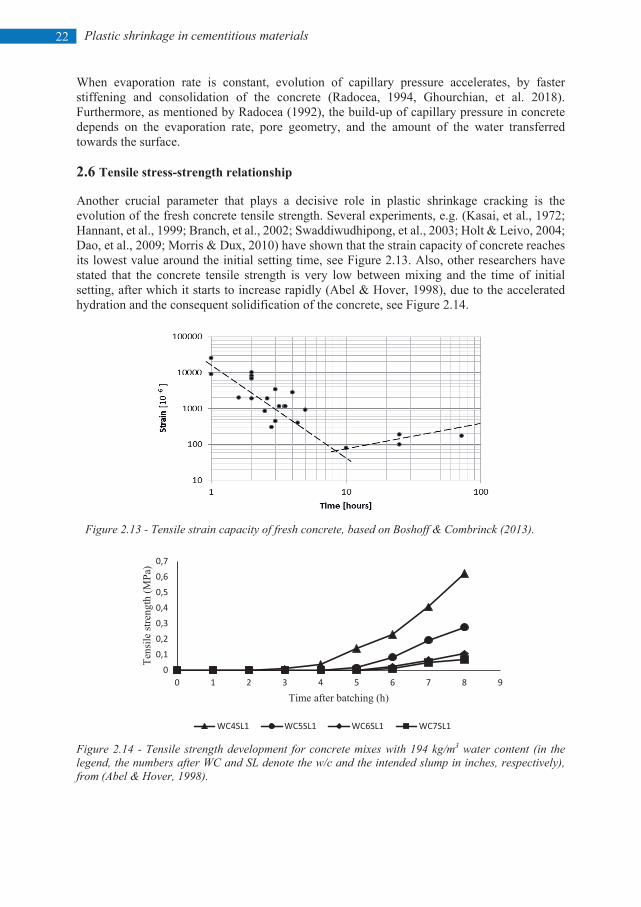
2.6 Tensile stress-strength relationship ....................................................................................... 22
2.7 Concluding remarks .................................................................................................................... 23
3. TEST METHODS AND MEASURING TECHNIQUES ............................................................. 25
3.1 Test methods.......................................................................................................................... 25
3.1.1 Restrained specimens .................................................................................................... 25
3.1.2 Unrestrained specimens ................................................................................................. 30
3.2 Measuring techniques ............................................................................................................ 30
3.2.1 Evaporation ................................................................................................................... 30
3.2.2 Bleeding......................................................................................................................... 30
3.2.3 Hydration heat ............................................................................................................... 30
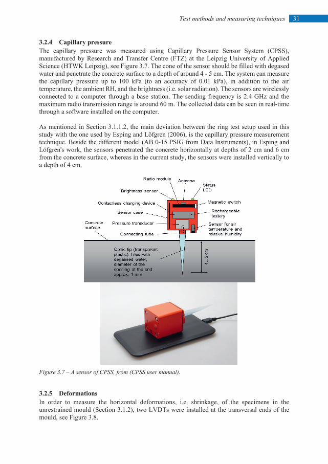
3.2.4 Capillary pressure .......................................................................................................... 31
VIII
3.2.5 Deformations ................................................................................................................. 31
3.2.6 Crack measurements ...................................................................................................... 32
3.3 Half-scale test ........................................................................................................................ 34
3.3 Concluding remarks .................................................................................................................... 36
4. EXPERIMENTAL RESULTS ...................................................................................................... 37
4.1 General .................................................................................................................................. 37
4.2 Effect of admixtures .................................................................................................................... 39
4.2.1 Retarder ................................................................................................................................ 42
4.2.2 Accelerator ........................................................................................................................... 42
4.2.3 Stabilizer ............................................................................................................................... 42
4.2.4 Air-entraining agent ............................................................................................................. 42
4.2.5 SRA ...................................................................................................................................... 42
4.3 Effect of steel fibres .............................................................................................................. 42
4.4 Effect of w/c .......................................................................................................................... 45
4.5 Effect of cement type .................................................................................................................. 46
4.6 Effect of coarse aggregate content .............................................................................................. 48
4.7 Effect of polycarboxylate ether based SP .................................................................................... 49
4.8 Half-scale test .............................................................................................................................. 50
4.9 Concluding remarks .................................................................................................................... 52
5 CRACKING SEVERITY MODEL ............................................................................................... 53
5.1 Introduction ........................................................................................................................... 53
5.2 Model formulation ................................................................................................................. 54
5.3 Limitations............................................................................................................................. 59
5.4 Concluding remarks .............................................................................................................. 59
6 DISCUSSION AND GENERAL CONCLUSIONS ..................................................................... 61
6.1 Discussion ............................................................................................................................. 61
6.2 Conclusions ........................................................................................................................... 65
6.3 Future work ........................................................................................................................... 66
REFERENCES ...................................................................................................................................... 67
DOCTORAL AND LICENTIATE THESES ........................................................................................ 75
Paper I-V
IX
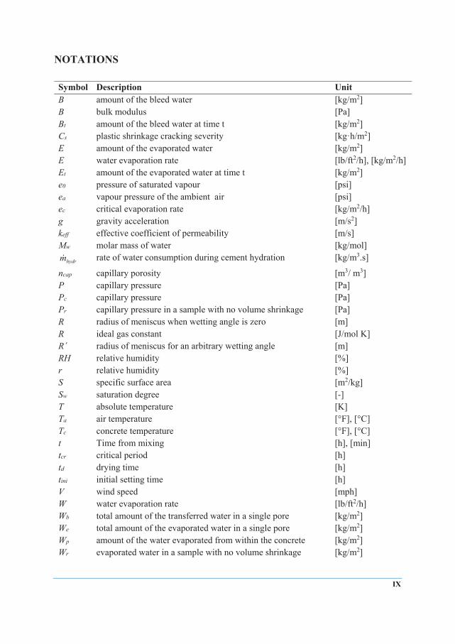
NOTATIONS Symbol Description Unit B amount of the bleed water [kg/m2] B bulk modulus [Pa] Bt amount of the bleed water at time t [kg/m2] Cs plastic shrinkage cracking severity [kg·h/m2] E amount of the evaporated water [kg/m2] E water evaporation rate [lb/ft2/h], [kg/m2/h] Et amount of the evaporated water at time t [kg/m2] e0 pressure of saturated vapour [psi] ea vapour pressure of the ambient air [psi] ec critical evaporation rate [kg/m2/h] g gravity acceleration [m/s2] keff effective coefficient of permeability [m/s] Mw molar mass of water [kg/mol]
hydrm rate of water consumption during cement hydration [kg/m3.s]
ncap capillary porosity [m3/ m3] P capillary pressure [Pa] Pc capillary pressure [Pa] Pr capillary pressure in a sample with no volume shrinkage [Pa] R radius of meniscus when wetting angle is zero [m] R ideal gas constant [J/mol K] R´ radius of meniscus for an arbitrary wetting angle [m] RH relative humidity [%] r relative humidity [%] S specific surface area [m2/kg] Sw saturation degree [-] T absolute temperature [K] Ta air temperature [°F], [°C] Tc concrete temperature [°F], [°C] t Time from mixing [h], [min] tcr critical period [h] td drying time [h] tini initial setting time [h] V wind speed [mph] W water evaporation rate [lb/ft2/h] Wb total amount of the transferred water in a single pore [kg/m2] We total amount of the evaporated water in a single pore [kg/m2] Wp amount of the water evaporated from within the concrete [kg/m2] Wr evaporated water in a sample with no volume shrinkage [kg/m2]
X
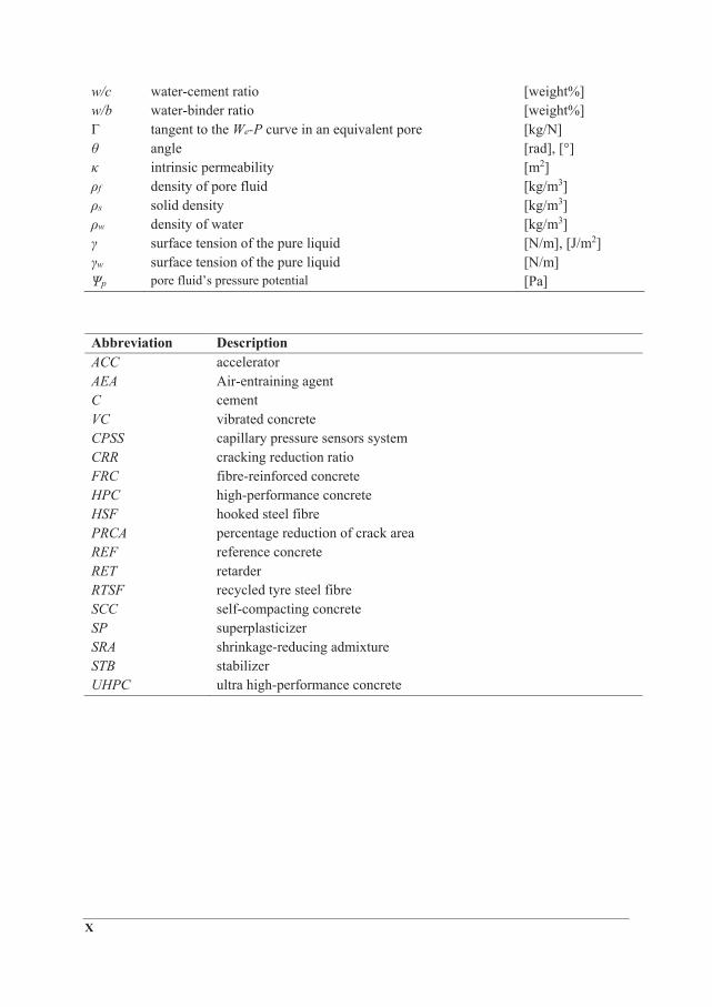
w/c water-cement ratio [weight%] w/b water-binder ratio [weight%] Γ tangent to the We-P curve in an equivalent pore [kg/N] θ angle [rad], [°] κ intrinsic permeability [m2] ρf density of pore fluid [kg/m3] ρs solid density [kg/m3] ρw density of water [kg/m3] γ surface tension of the pure liquid [N/m], [J/m2] γw surface tension of the pure liquid [N/m] Ѱp pore fluid’s pressure potential [Pa]
Abbreviation Description ACC accelerator AEA Air-entraining agent C cement VC vibrated concrete CPSS capillary pressure sensors system CRR cracking reduction ratio FRC fibre-reinforced concrete HPC high-performance concrete HSF hooked steel fibre PRCA percentage reduction of crack area REF reference concrete RET retarder RTSF recycled tyre steel fibre SCC self-compacting concrete SP superplasticizer SRA shrinkage-reducing admixture STB stabilizer UHPC ultra high-performance concrete

Part I

1 Introduction
1. INTRODUCTION 1.1 Background Durability and functionality of concrete structures are closely related to whether they are crack free during their life-span or not. However, if the concrete member is subjected to high levels of shrinkage, cracks may form, which impair the durability and sustainability of the structure, by providing passages for harmful materials, to ingress into the concrete bulk (Larch, 1957; Tutti, 1982: Jonasson, 1994; Hedlund, 2000; Carlswärd, 2006; Carlswärd & Emborg, 2014).
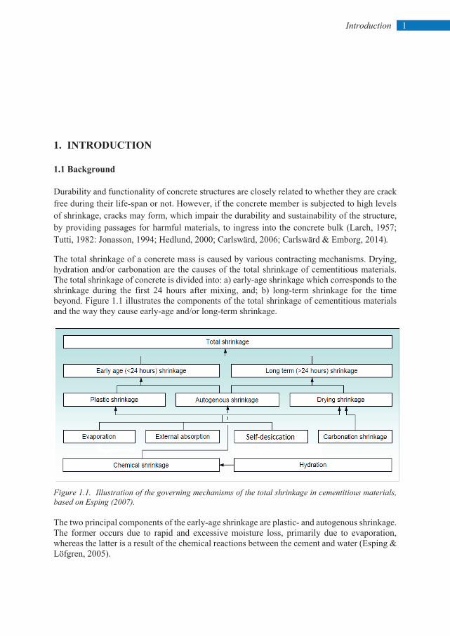
The total shrinkage of a concrete mass is caused by various contracting mechanisms. Drying, hydration and/or carbonation are the causes of the total shrinkage of cementitious materials. The total shrinkage of concrete is divided into: a) early-age shrinkage which corresponds to the shrinkage during the first 24 hours after mixing, and; b) long-term shrinkage for the time beyond. Figure 1.1 illustrates the components of the total shrinkage of cementitious materials and the way they cause early-age and/or long-term shrinkage.
Figure 1.1. Illustration of the governing mechanisms of the total shrinkage in cementitious materials, based on Esping (2007). The two principal components of the early-age shrinkage are plastic- and autogenous shrinkage. The former occurs due to rapid and excessive moisture loss, primarily due to evaporation, whereas the latter is a result of the chemical reactions between the cement and water (Esping & Löfgren, 2005).
2 Introduction
Plastic shrinkage, the subject of this research, occurs between the time of the concrete placement and the final set, while the mixture has not yet gained enough tensile strength (Revina & Shalon, 1964; Powers, 1968). ACI 305R (1999) defines the plastic shrinkage cracking as a phenomenon which, "is frequently associated with hot weather concreting in arid climates. It occurs in exposed concrete, primarily in flat work but also in beams and footings and may develop in other climates whenever the evaporation rate is greater than the rate at which the water rises to the surface of recently placed concrete by bleeding".
Experienced site managers have thus, gained the knowledge of how to avoid this type of cracking by taking immediate measures, if the weather condition at and shortly after casting was not suitable, e.g. high temperature, low relative humidity, strong winds, and sunshine. Otherwise, repairing the cracked structures due to plastic shrinkage may be expensive, where it has been estimated to cost around 3M € annually, only in Sweden. This can be extrapolated to around 150M € for the whole EU region, based on a 4.5M m3 of ready mixed concrete (RMC) in Sweden, compared to 245M m3 in EU, according to the European ready mixed concrete association (ERMCO Statistics, 2017). Once the concrete is placed, its solid particles tend to settle due to gravity, draining the water in the pore system to the surface. The accumulated water (if bleeding rate is higher than evaporation rate), gradually evaporates until the concrete surface is completely dry. In such case, a negative hydraulic pressure, also known as capillary pressure, builds-up in the pore system (Radocea, 1992; Qi, et al., 2003; Josserand, et al. 2006; Schmidt & Slowik, 2013), which in turn generates tensile stresses in the concrete mass (if the concrete member is restrained internally and/or externally). Plastic shrinkage cracking happens when the internal tensile stresses surpass the relatively low tensile strength of the fresh concrete (Boshoff & Combrinck, 2013).
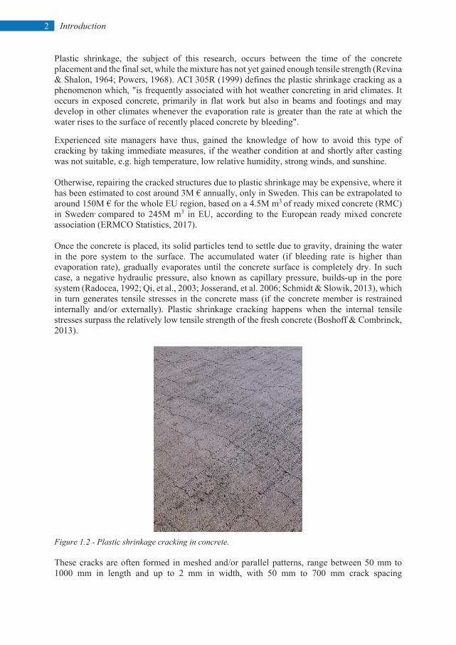
Figure 1.2 - Plastic shrinkage cracking in concrete. These cracks are often formed in meshed and/or parallel patterns, range between 50 mm to 1000 mm in length and up to 2 mm in width, with 50 mm to 700 mm crack spacing
3 Introduction
(Kosmatka, et al., 2002). Horizontal concrete elements with high surface-volume ratio, such as slabs and pavements, are more susceptible to plastic shrinkage cracking (Powers, 1968). A broad collection of variables, such as, w/b, cement type, fibres, admixture, member size, fines content, and the ambient conditions (i.e. relative humidity, air temperature, and wind velocity) may affect the cracking severity of a fresh concrete (Uno 1998; Boshoff & Combrinck, 2013; Lura, et al. 2007). Many researchers have performed a significant number of experiments and studies in order to mitigate the risk plastic shrinkage cracking in concrete. For instance, among others, the impact of water-cement ratio (w/c), coarse aggregate content, and dosage of superplasticizer has been investigated by Esping and Löfgren (2005). They reported that the cracking decreased by higher coarse aggregate content and lower SP dosage. Furthermore, they concluded that w/c of 0.55 is optimum for having the least cracking tendency. Lura et al. (2007), Mora-Ruacho et al. (2009), and Saliba et al. (2011) studied the effect of shrinkage-reducing admixture (SRA) on shrinkage of plastic mortar and concrete, where all found out that SRA notably reduces the cracking tendency. The influence of admixtures on plastic shrinkage cracking of self-compacting concrete (SCC) was studied by Leeman et al. (2014), and Combrick et al. (2019). The role and the mechanism of capillary pressure was extensively investigated by Slowik and Schmidt (2008, 2010). The research performed in Scandinavia on plastic shrinkage can be traced back to mid-1980s, where researchers such as Hedin (1985), Radocea (1992), Johansen & Dahl (1993), Lund et al. (1997), Hammer (1999), Esping and Löfgren (2005), and Bertelsen (2018) studied different aspects of the phenomenon and prepared a strong basis for further investigations. In studying early-age cracking in concrete, it is important to distinguish between the cracks caused by plastic shrinkage, and those induced by autogenous shrinkage. Once the cracking mechanism is identified, the proper measure can be applied in order to reduce the cracking risk. For instance if the concrete is considered susceptible to plastic shrinkage, reducing the amount of the evaporated water by covering or fogging the concrete surface, or using wind breaker, can be effective in mitigating the cracking risk (Slowik & Schmidt, 2008). Otherwise, the autogenous shrinkage can be reduced by adding, for example, SRA to the mixture. During this research, it has been noted that cracking in plastic concrete is a result of a complex relationship between interconnected parameters such as evaporation, capillary pressure, and hydration rate. Also, it has been observed that, relating the cracking severity, solely to the evaporation rate, is ambiguous and sometimes wrong, as concretes may possess different evaporation rates with disproportionate cracking. Furthermore, based on experience from building sites, it was also noted that the occurrence of plastic shrinkage cracking has increased during the past decades. Nowadays, in commonly used concretes such as SCC and other high performance concrete, plastic shrinkage can be highly problematic (Gram & Piiparinen, 1999; Esping & Löfgren, 2005), due to their relatively low w/b, in addition to high content of stabilizing filler and water-reducing admixtures, i.e. superplasticizer. Thus, this type of cracking is not limited only to hot and arid countries, but also has become a challenge even in the cold Scandinavia. The significance of plastic shrinkage cracking in the Scandinavian countries, may be comprehended from Kompen's (1994) final remarks in his internal report about a bridge construction project in Norway (Hammer, 2007):
4 Introduction
“The plastic cracking phenomenon is regarded the most serious problem met in using low w/b-ratio concrete. There are serious worries that this phenomenon will jeopardise the quality improvements intended by the use of low w/b concretes. By observation in the field and full-scale trials a lot of experience has been gained on how to reduce cracking to a more acceptable level. Understanding of the mechanisms involved has, however, not reached such a level that this cracking can be completely avoided in every construction work. Consequently, it is strongly recommended that research should continue on introduction of early age cracking problem, to develop both basic understanding and practical use”.
During the literature study, it has been noted that the rate at which capillary pressure increases has been neglected in contrast to its absolute value. As it will be explained later, the rate of the capillary pressure is directly proportional to the tensile stress level in the concrete mass. Thus, a knowledge gap regarding the role of the capillary pressure build-up rate (not the absolute value) in plastic shrinkage has been identified and extensively addressed in this research. 1.2 Hypothesis, aim and research questions Hypothesis: A complex correlation between evaporation, capillary pressure, and hydration rate, is the driving force behind plastic shrinkage cracking in cementitious materials. Aim: Gaining more knowledge about the mechanism of plastic shrinkage of concrete and modelling the phenomenon. In this regard, the role of capillary pressure build-up rate and the hydration process has been specially investigated in this research. The final outcomes are a number of pre- and post-casting measures which form a general guideline to mitigate the cracking risk in plastic concrete. Research questions: The research was adapted and formulated in order to answer the following questions: RQ1 – Is water evaporation really the main reason behind plastic shrinkage cracking of young
concrete? RQ2 – What is the role of capillary pressure and hydration rate in the cracking process? RQ3 – In which way are vertical and horizontal deformations involved in plastic shrinkage
cracking? RQ4 – Can the effects of parameters related to mix design be graded and quantified
individually? RQ5 – Is it possible to model the phenomenon in a proper way based on the experimental results
and the research hypothesis?
5 Introduction
1.3 Scientific approach This study started by an intensive literature review on topics that are related to the early-age behaviour of concrete. This broad collection of references included papers from 1941 and onwards, based on which, the knowledge gap and the neglected aspects were identified. Accordingly, the research was focused on the role of capillary pressure, since the results reported in the literature did not look logical, due to, according to the author's opinion, some misinterpretation. The fundamental scientific approach of this project, thus, is based on identifying the relationship between the evaporation, capillary pressure, and the hydration rate. The hypothesis was tested to address the research questions, by performing series of laboratory tests, utilizing four experimental setups. Each test setup was partly modified in order to include more measurements and increase the accuracy, compared to the standard version. Influence of cement type, w/c, SP dosage, accelerators, retarders, SRA, air-entraining agents, stabilizers, and steel fibres on the plastic shrinkage cracking of the specimens were studied. To check the validity of the experimental results, they were compared with the outcomes of five half-scale tests. Recommendations were then made in order to decrease the cracking risk. Eventually, a model was proposed to predict the cracking severity of plastic concrete, which can be used prior to casting. 1.4 Limitations The large number of variables that may affect the shrinkage and cracking of plastic cement based materials, makes it difficult to examine and identify the effect of all. Thus, only variables which were considered the most important, were included in this research. In addition, due to the interconnected nature of these variables, it is almost impossible to modify the amount of one constituent, without substituting, adding and/or adjusting the amount of others, which makes it difficult to study them independently. Furthermore, in studying cementitious materials, the high dependency of the results, on the experimental setups and the measuring techniques, must be taken into the account, especially when compared to results reported by others. This is most critical in modelling the phenomenon. 1.5 Disposition of the thesis This PhD thesis consists of 6 chapters which are briefly described below: Chapter 1 generally describes the conducted research by presenting background, hypothesis, aims, and the scientific approach of the project. Chapter 2 explains the mechanism of the plastic shrinkage cracking in concrete and the main affecting factors. Chapter 3 describes the utilized experimental methods, test setups and the measuring techniques.
6 Introduction
Chapter 4 presents the results of the laboratory work and the half-scale tests. Chapter 5 explains and discusses the proposed model to predict the severity of plastic shrinkage cracking. Chapter 6 concludes the thesis based on the research findings, highlighting the most important ones, and presents suggestions for future research. 1.6 Appended papers Paper I
”Plastic Shrinkage Cracking in Concrete: State of the Art”, Sayahi, F., Emborg, M. and Hedlund, H., published in Nordic Concrete Research, Vol. 51, No. 3, December 2014, pp. 95 – 110.
Paper I presents a state of the art, in which previous studies are summarized. Mechanism of plastic shrinkage cracking is explained and the role of various parameters is described. In addition, the effect of several variables is briefly discussed. Paper II
”Effect of admixtures on the mechanism of plastic shrinkage cracking in self-compacting concrete”, Sayahi, F., Emborg, M. and Hedlund, H., Cwirzen, A., Submitted.
In Paper II, Influence of admixtures, such as accelerators, retarders, SRA, air-entraining agent, and stabilizers on plastic shrinkage cracking in SCC is investigated. It was observed that the specific types of accelerator and retarder increase the cracking tendency of the plastic concrete, while stabilizer, air-entraining agent, and SRA decrease the cracking potential. Moreover, the vertical and horizontal deformations of the cracked specimens were indirectly proportional. Paper III
”Effect of Steel Fibres Extracted from Recycled Tyres on Plastic Shrinkage Cracking of Self-Compacting Concrete”, Sayahi, F., Emborg, M., Hedlund, H., Cwirzen, A., Submitted.
Paper III discusses the effect of steel fibres, obtained from recycled tires on plastic shrinkage cracking in concrete. The results are compared with another type of commercially available steel fibre. It was observed that the fibres significantly decreased the volumetric shrinkage, evaporation, and the crack area of the plain concrete. Paper IV
”Plastic Shrinkage Cracking of Self-compacting Concrete: Influence of Capillary Pressure and Dormant Period”, Sayahi, F., Emborg, M., Hedlund, H., Cwirzen, A., Submitted.
The paper reports experimental results performed to study the effect of w/c ratio, cement type, and SP on the plastic shrinkage cracking of SCC. The results are then used to explain the role of the capillary pressure and length of the hydration dormant period in the cracking process. The findings of paper IV form the basis of the model presented in Paper V.
7 Introduction
Paper V ”The Severity of Plastic Shrinkage Cracking in Concrete: A New Model”, Sayahi, F., Emborg, M., Hedlund, H., Cwirzen, A., Stelmarczyk, M., Submitted.
In this paper a model is proposed for estimating the severity of plastic shrinkage cracking in concrete. The model is based on the effect of the capillary pressure build-up rate and the concrete initial set on cracking. Accordingly, by calculating the amount of the evaporated water from within the concrete and knowing the initial setting time, the cracking severity can be estimated, prior to casting. 1.7 Additional publications Other publication by the author which are not appended in this PhD thesis are listed below. 1.7.1 Conference papers ”Plastic Shrinkage Cracking in Concrete: Research in Scandinavia”, Sayahi, F., Emborg, M. and Hedlund, H., published in proceeding of the XXII Nordic Concrete Research symposium, Reykjavik, Iceland, August 13 – 15, 2014, pp. 351 – 354. ”Plastic Shrinkage Cracking in Self-Compacting Concrete: a Parametric Study”, Sayahi, F., Emborg, M. and Hedlund, H. Löfgren, I., published in proceeding of the international RILEM conference on Materials, Systems and Structures in Civil Engineering, MSSCE 2016, Lyngby, Denmark, August 22 – 24, 2016, pp. 609 – 619. “Effect of Water-Cement Ratio on Plastic Shrinkage Cracking in Self-Compacting Concrete” Sayahi, F., Emborg, M. and Hedlund, H., published in proceeding of the XXIII Nordic Concrete Research symposium, Aalborg, Denmark, August 21 – 23, 2017, pp. 339 – 342. “Plastic Shrinkage Cracking in Concrete – Influence of Test Methods” Sayahi, F., Emborg, M. and Hedlund, H., Proceeding of the Early Age Cracking and Serviceability in Cement-Bases Materials and Structures, EAC02, Brussels, Belgium, September 12 – 14, 2017, pp. 773 – 778. 1.7.2 Technical reports "Application of ILD2300-10 Laser Sensor on Measuring the Vertical Displacement of Fresh Concrete Surface". Sayahi, F., Luleå University of Technology, 2017.
1.7.3 Licentiate thesis “Plastic shrinkage cracking in concrete”. Sayahi, F., Department of Civil, Environmental and Natural Resources Engineering, Luleå University of Technology, 2016, p. 142.

9 Plastic shrinkage in cementitious materials
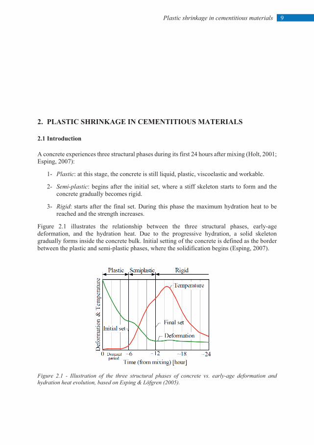
2. PLASTIC SHRINKAGE IN CEMENTITIOUS MATERIALS 2.1 Introduction A concrete experiences three structural phases during its first 24 hours after mixing (Holt, 2001; Esping, 2007):
1- Plastic: at this stage, the concrete is still liquid, plastic, viscoelastic and workable.
2- Semi-plastic: begins after the initial set, where a stiff skeleton starts to form and the concrete gradually becomes rigid.
3- Rigid: starts after the final set. During this phase the maximum hydration heat to be reached and the strength increases.
Figure 2.1 illustrates the relationship between the three structural phases, early-age deformation, and the hydration heat. Due to the progressive hydration, a solid skeleton gradually forms inside the concrete bulk. Initial setting of the concrete is defined as the border between the plastic and semi-plastic phases, where the solidification begins (Esping, 2007).
Figure 2.1 - Illustration of the three structural phases of concrete vs. early-age deformation and hydration heat evolution, based on Esping & Löfgren (2005).
Plastic shrinkage in cementitious materials
10
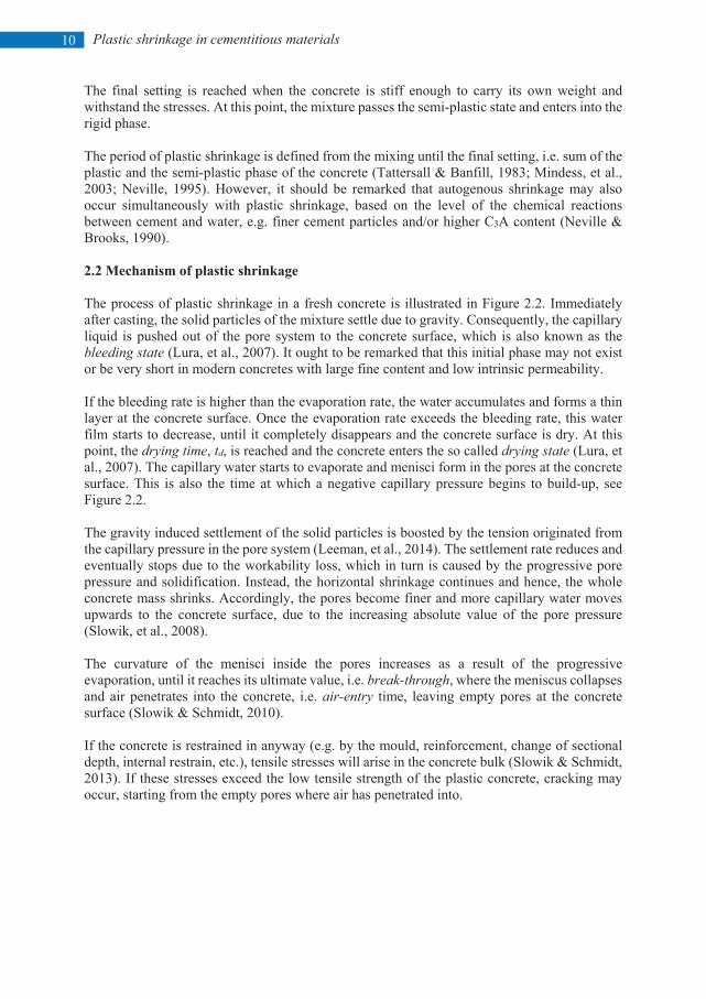
The final setting is reached when the concrete is stiff enough to carry its own weight and withstand the stresses. At this point, the mixture passes the semi-plastic state and enters into the rigid phase. The period of plastic shrinkage is defined from the mixing until the final setting, i.e. sum of the plastic and the semi-plastic phase of the concrete (Tattersall & Banfill, 1983; Mindess, et al., 2003; Neville, 1995). However, it should be remarked that autogenous shrinkage may also occur simultaneously with plastic shrinkage, based on the level of the chemical reactions between cement and water, e.g. finer cement particles and/or higher C3A content (Neville & Brooks, 1990). 2.2 Mechanism of plastic shrinkage The process of plastic shrinkage in a fresh concrete is illustrated in Figure 2.2. Immediately after casting, the solid particles of the mixture settle due to gravity. Consequently, the capillary liquid is pushed out of the pore system to the concrete surface, which is also known as the bleeding state (Lura, et al., 2007). It ought to be remarked that this initial phase may not exist or be very short in modern concretes with large fine content and low intrinsic permeability. If the bleeding rate is higher than the evaporation rate, the water accumulates and forms a thin layer at the concrete surface. Once the evaporation rate exceeds the bleeding rate, this water film starts to decrease, until it completely disappears and the concrete surface is dry. At this point, the drying time, td, is reached and the concrete enters the so called drying state (Lura, et al., 2007). The capillary water starts to evaporate and menisci form in the pores at the concrete surface. This is also the time at which a negative capillary pressure begins to build-up, see Figure 2.2. The gravity induced settlement of the solid particles is boosted by the tension originated from the capillary pressure in the pore system (Leeman, et al., 2014). The settlement rate reduces and eventually stops due to the workability loss, which in turn is caused by the progressive pore pressure and solidification. Instead, the horizontal shrinkage continues and hence, the whole concrete mass shrinks. Accordingly, the pores become finer and more capillary water moves upwards to the concrete surface, due to the increasing absolute value of the pore pressure (Slowik, et al., 2008). The curvature of the menisci inside the pores increases as a result of the progressive evaporation, until it reaches its ultimate value, i.e. break-through, where the meniscus collapses and air penetrates into the concrete, i.e. air-entry time, leaving empty pores at the concrete surface (Slowik & Schmidt, 2010). If the concrete is restrained in anyway (e.g. by the mould, reinforcement, change of sectional depth, internal restrain, etc.), tensile stresses will arise in the concrete bulk (Slowik & Schmidt, 2013). If these stresses exceed the low tensile strength of the plastic concrete, cracking may occur, starting from the empty pores where air has penetrated into.
11 Plastic shrinkage in cementitious materials
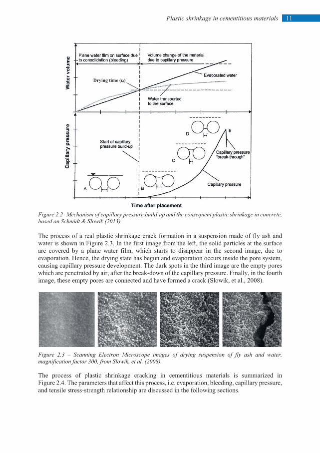
Figure 2.2- Mechanism of capillary pressure build-up and the consequent plastic shrinkage in concrete, based on Schmidt & Slowik (2013) The process of a real plastic shrinkage crack formation in a suspension made of fly ash and water is shown in Figure 2.3. In the first image from the left, the solid particles at the surface are covered by a plane water film, which starts to disappear in the second image, due to evaporation. Hence, the drying state has begun and evaporation occurs inside the pore system, causing capillary pressure development. The dark spots in the third image are the empty pores which are penetrated by air, after the break-down of the capillary pressure. Finally, in the fourth image, these empty pores are connected and have formed a crack (Slowik, et al., 2008).
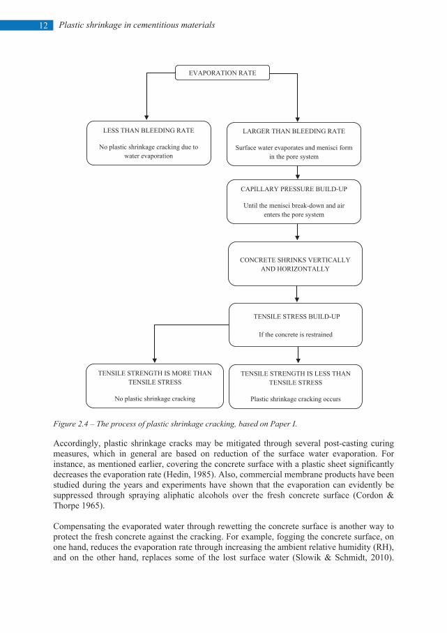
Figure 2.3 – Scanning Electron Microscope images of drying suspension of fly ash and water, magnification factor 300, from Slowik, et al. (2008). The process of plastic shrinkage cracking in cementitious materials is summarized in Figure 2.4. The parameters that affect this process, i.e. evaporation, bleeding, capillary pressure, and tensile stress-strength relationship are discussed in the following sections.
Drying time (td)
Plastic shrinkage in cementitious materials
12
Figure 2.4 – The process of plastic shrinkage cracking, based on Paper I. Accordingly, plastic shrinkage cracks may be mitigated through several post-casting curing measures, which in general are based on reduction of the surface water evaporation. For instance, as mentioned earlier, covering the concrete surface with a plastic sheet significantly decreases the evaporation rate (Hedin, 1985). Also, commercial membrane products have been studied during the years and experiments have shown that the evaporation can evidently be suppressed through spraying aliphatic alcohols over the fresh concrete surface (Cordon & Thorpe 1965). Compensating the evaporated water through rewetting the concrete surface is another way to protect the fresh concrete against the cracking. For example, fogging the concrete surface, on one hand, reduces the evaporation rate through increasing the ambient relative humidity (RH), and on the other hand, replaces some of the lost surface water (Slowik & Schmidt, 2010).
EVAPORATION RATE
LESS THAN BLEEDING RATE
No plastic shrinkage cracking due to water evaporation
LARGER THAN BLEEDING RATE
Surface water evaporates and menisci form in the pore system
CAPILLARY PRESSURE BUILD-UP
Until the menisci break-down and air enters the pore system
TENSILE STRESS BUILD-UP
If the concrete is restrained
TENSILE STRENGTH IS MORE THAN TENSILE STRESS
No plastic shrinkage cracking
TENSILE STRENGTH IS LESS THAN TENSILE STRESS
Plastic shrinkage cracking occurs
CONCRETE SHRINKS VERTICALLY
AND HORIZONTALLY
13 Plastic shrinkage in cementitious materials
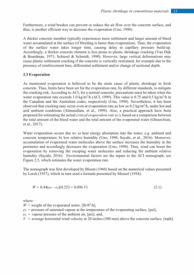
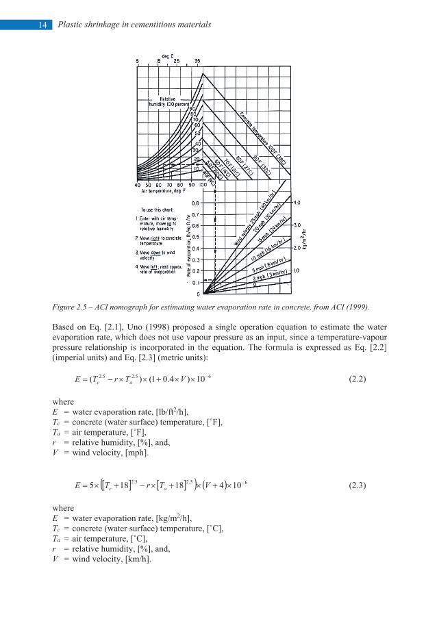
Furthermore, a wind breaker can prevent or reduce the air flow over the concrete surface, and thus, is another efficient way to decrease the evaporation (Uno, 1998). A thicker concrete member typically experiences more settlement and larger amount of bleed water accumulated at the surface (if bleeding is faster than evaporation). Thus, the evaporation of the surface water takes longer time, causing delay in capillary pressure build-up. Accordingly, a thicker concrete element is less prone to plastic shrinkage cracking (Van Dijk & Boardman, 1971; Schiessl & Schmidt, 1990). However, large vertical deformations may cause plastic settlement cracking if the concrete is vertically restrained, for example due to the presence of reinforcement bars, differential settlement and/or change of sectional depth. 2.3 Evaporation As mentioned evaporation is believed to be the main cause of plastic shrinkage in fresh concrete. Thus, limits have been set for the evaporation rate, by different standards, to mitigate the cracking risk. According to ACI, for a normal concrete, precautions must be taken when the water evaporation rate exceeds 1.0 kg/m2/h (ACI, 1999). This value is 0.75 and 0.5 kg/m2/h in the Canadian and the Australian codes, respectively (Uno, 1998). Nevertheless, it has been observed that cracking may occur even at evaporation rate as low as 0.2 kg/m2/h, under hot and arid ambient conditions (Almusallam, et al., 1999). Also, a practical approach have been proposed for estimating the actual critical evaporation rate (ec), based on a comparison between the total amount of the bleed water and the total amount of the evaporated water (Ghourchian, et al., 2017). Water evaporation occurs due to: a) heat energy absorption into the water, e.g. ambient and concrete temperature; b) low relative humidity (Uno, 1998; Sayahi, et al., 2016). Moreover, accumulation of evaporated water molecules above the surface increases the humidity in the perimeter and accordingly decreases the evaporation (Uno, 1998). Thus, wind can boost the evaporation by removing the escaping water molecules and reducing the ambient relative humidity (Sayahi, 2016). Environmental factors are the inputs to the ACI nomograph, see Figure 2.5, which estimates the water evaporation rate. The nomograph was first developed by Bloem (1960) based on the numerical values presented by Lerch (1957), which in turn used a formula presented by Menzel (1954):
W = 0.44(e0 – ea)(0.253 + 0.096 V) (2.1)
where: W = weight of the evaporated water, [lb/ft2/h], e0 = pressure of saturated vapour at the temperature of the evaporating surface, [psi], ea = vapour pressure of the ambient air, [psi], and, V = average horizontal wind velocity at 20 inches (500 mm) above the concrete surface, [mph].
Plastic shrinkage in cementitious materials
14
Figure 2.5 – ACI nomograph for estimating water evaporation rate in concrete, from ACI (1999). Based on Eq. [2.1], Uno (1998) proposed a single operation equation to estimate the water evaporation rate, which does not use vapour pressure as an input, since a temperature-vapour pressure relationship is incorporated in the equation. The formula is expressed as Eq. [2.2] (imperial units) and Eq. [2.3] (metric units):
65.25.2 10)4.01()( −××+××−= VTrTE ac (2.2) where E = water evaporation rate, [lb/ft2/h], Tc = concrete (water surface) temperature, [˚F], Ta = air temperature, [˚F], r = relative humidity, [%], and, V = wind velocity, [mph].
][ ][( ) ( ) 65.25.2 10418185 −×+×+×−+×= VTrTE ac (2.3) where E = water evaporation rate, [kg/m2/h], Tc = concrete (water surface) temperature, [˚C], Ta = air temperature, [˚C], r = relative humidity, [%], and, V = wind velocity, [km/h].
15 Plastic shrinkage in cementitious materials
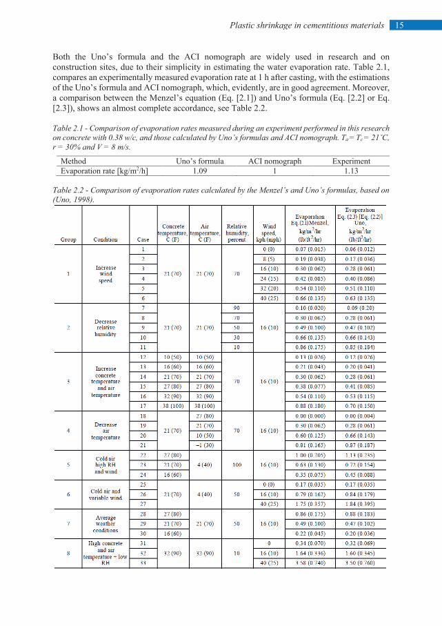
Both the Uno’s formula and the ACI nomograph are widely used in research and on construction sites, due to their simplicity in estimating the water evaporation rate. Table 2.1, compares an experimentally measured evaporation rate at 1 h after casting, with the estimations of the Uno’s formula and ACI nomograph, which, evidently, are in good agreement. Moreover, a comparison between the Menzel’s equation (Eq. [2.1]) and Uno’s formula (Eq. [2.2] or Eq. [2.3]), shows an almost complete accordance, see Table 2.2. Table 2.1 - Comparison of evaporation rates measured during an experiment performed in this research on concrete with 0.38 w/c, and those calculated by Uno’s formulas and ACI nomograph. Ta = Tc = 21˚C, r = 30% and V = 8 m/s.
Method Uno’s formula ACI nomograph Experiment Evaporation rate [kg/m2/h] 1.09 1 1.13
Table 2.2 - Comparison of evaporation rates calculated by the Menzel’s and Uno’s formulas, based on (Uno, 1998).
Plastic shrinkage in cementitious materials
16
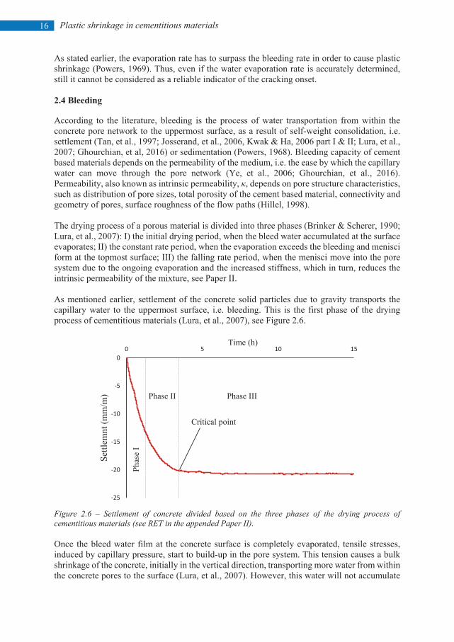
As stated earlier, the evaporation rate has to surpass the bleeding rate in order to cause plastic shrinkage (Powers, 1969). Thus, even if the water evaporation rate is accurately determined, still it cannot be considered as a reliable indicator of the cracking onset. 2.4 Bleeding According to the literature, bleeding is the process of water transportation from within the concrete pore network to the uppermost surface, as a result of self-weight consolidation, i.e. settlement (Tan, et al., 1997; Josserand, et al., 2006, Kwak & Ha, 2006 part I & II; Lura, et al., 2007; Ghourchian, et al, 2016) or sedimentation (Powers, 1968). Bleeding capacity of cement based materials depends on the permeability of the medium, i.e. the ease by which the capillary water can move through the pore network (Ye, et al., 2006; Ghourchian, et al., 2016). Permeability, also known as intrinsic permeability, κ, depends on pore structure characteristics, such as distribution of pore sizes, total porosity of the cement based material, connectivity and geometry of pores, surface roughness of the flow paths (Hillel, 1998). The drying process of a porous material is divided into three phases (Brinker & Scherer, 1990; Lura, et al., 2007): I) the initial drying period, when the bleed water accumulated at the surface evaporates; II) the constant rate period, when the evaporation exceeds the bleeding and menisci form at the topmost surface; III) the falling rate period, when the menisci move into the pore system due to the ongoing evaporation and the increased stiffness, which in turn, reduces the intrinsic permeability of the mixture, see Paper II. As mentioned earlier, settlement of the concrete solid particles due to gravity transports the capillary water to the uppermost surface, i.e. bleeding. This is the first phase of the drying process of cementitious materials (Lura, et al., 2007), see Figure 2.6.
Figure 2.6 – Settlement of concrete divided based on the three phases of the drying process of cementitious materials (see RET in the appended Paper II). Once the bleed water film at the concrete surface is completely evaporated, tensile stresses, induced by capillary pressure, start to build-up in the pore system. This tension causes a bulk shrinkage of the concrete, initially in the vertical direction, transporting more water from within the concrete pores to the surface (Lura, et al., 2007). However, this water will not accumulate
-25
-20
-15
-10
-5
00 5 10 15
Settl
emnt
(mm
/m)
Time (h)
Critical point
Phas
e I
Phase II Phase III
17 Plastic shrinkage in cementitious materials
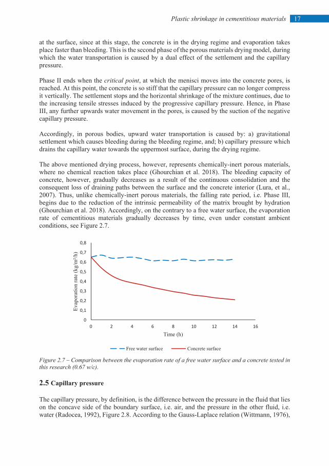
at the surface, since at this stage, the concrete is in the drying regime and evaporation takes place faster than bleeding. This is the second phase of the porous materials drying model, during which the water transportation is caused by a dual effect of the settlement and the capillary pressure. Phase II ends when the critical point, at which the menisci moves into the concrete pores, is reached. At this point, the concrete is so stiff that the capillary pressure can no longer compress it vertically. The settlement stops and the horizontal shrinkage of the mixture continues, due to the increasing tensile stresses induced by the progressive capillary pressure. Hence, in Phase III, any further upwards water movement in the pores, is caused by the suction of the negative capillary pressure. Accordingly, in porous bodies, upward water transportation is caused by: a) gravitational settlement which causes bleeding during the bleeding regime, and; b) capillary pressure which drains the capillary water towards the uppermost surface, during the drying regime. The above mentioned drying process, however, represents chemically-inert porous materials, where no chemical reaction takes place (Ghourchian et al. 2018). The bleeding capacity of concrete, however, gradually decreases as a result of the continuous consolidation and the consequent loss of draining paths between the surface and the concrete interior (Lura, et al., 2007). Thus, unlike chemically-inert porous materials, the falling rate period, i.e. Phase III, begins due to the reduction of the intrinsic permeability of the matrix brought by hydration (Ghourchian et al. 2018). Accordingly, on the contrary to a free water surface, the evaporation rate of cementitious materials gradually decreases by time, even under constant ambient conditions, see Figure 2.7.
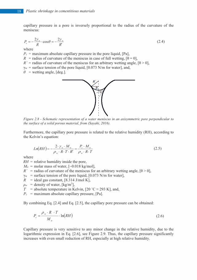
Figure 2.7 – Comparison between the evaporation rate of a free water surface and a concrete tested in this research (0.67 w/c). 2.5 Capillary pressure The capillary pressure, by definition, is the difference between the pressure in the fluid that lies on the concave side of the boundary surface, i.e. air, and the pressure in the other fluid, i.e. water (Radocea, 1992), Figure 2.8. According to the Gauss-Laplace relation (Wittmann, 1976),
0
0,1
0,2
0,3
0,4
0,5
0,6
0,7
0,8
0 2 4 6 8 10 12 14 16
Evap
orat
ion
rate
(kg/
m²/h
)
Time (h)
Free water surface Concrete surface
Plastic shrinkage in cementitious materials
18
capillary pressure in a pore is inversely proportional to the radius of the curvature of the meniscus:
RRP ww
c ′−=⋅−=
γθγ 2cos2 (2.4)
where Pc = maximum absolute capillary pressure in the pore liquid, [Pa], R = radius of curvature of the meniscus in case of full wetting, [θ = 0], R´ = radius of curvature of the meniscus for an arbitrary wetting angle, [θ > 0], γw = surface tension of the pore liquid, [0.073 N/m for water], and, θ = wetting angle, [deg.].
Figure 2.8 - Schematic representation of a water meniscus in an axisymmetric pore perpendicular to the surface of a solid porous material, from (Sayahi, 2016). Furthermore, the capillary pore pressure is related to the relative humidity (RH), according to the Kelvin’s equation:
( )TR
MPRTR
MRHLnw
wc
w
ww
⋅⋅⋅
=′⋅⋅⋅
⋅⋅−=
ρργ2 (2.5)
where RH = relative humidity inside the pore, Mw = molar mass of water, [~0.018 kg/mol], R´ = radius of curvature of the meniscus for an arbitrary wetting angle, [θ > 0], γw = surface tension of the pore liquid, [0.073 N/m for water], R = ideal gas constant, [8.314 J/mol K], ρw = density of water, [kg/m3], T = absolute temperature in Kelvin, [20 ˚C ≈ 293 K], and, Pc = maximum absolute capillary pressure, [Pa]. By combining Eq. [2.4] and Eq. [2.5], the capillary pore pressure can be obtained:
( )RHM
TRP
w
wc ln⋅
⋅⋅=ρ
(2.6)
Capillary pressure is very sensitive to any minor change in the relative humidity, due to the logarithmic expression in Eq. [2.6], see Figure 2.9. Thus, the capillary pressure significantly increases with even small reduction of RH, especially at high relative humidity.
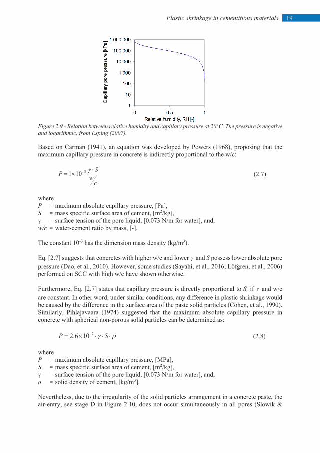
19 Plastic shrinkage in cementitious materials
Figure 2.9 - Relation between relative humidity and capillary pressure at 20°C. The pressure is negative and logarithmic, from Esping (2007). Based on Carman (1941), an equation was developed by Powers (1968), proposing that the maximum capillary pressure in concrete is indirectly proportional to the w/c:
cw
SP ⋅×= − γ3101 (2.7)
where P = maximum absolute capillary pressure, [Pa], S = mass specific surface area of cement, [m2/kg], γ = surface tension of the pore liquid, [0.073 N/m for water], and, w/c = water-cement ratio by mass, [-]. The constant 10-3 has the dimension mass density (kg/m3). Eq. [2.7] suggests that concretes with higher w/c and lower γ and S possess lower absolute pore pressure (Dao, et al., 2010). However, some studies (Sayahi, et al., 2016; Löfgren, et al., 2006) performed on SCC with high w/c have shown otherwise. Furthermore, Eq. [2.7] states that capillary pressure is directly proportional to S, if γ and w/c are constant. In other word, under similar conditions, any difference in plastic shrinkage would be caused by the difference in the surface area of the paste solid particles (Cohen, et al., 1990). Similarly, Pihlajavaara (1974) suggested that the maximum absolute capillary pressure in concrete with spherical non-porous solid particles can be determined as:
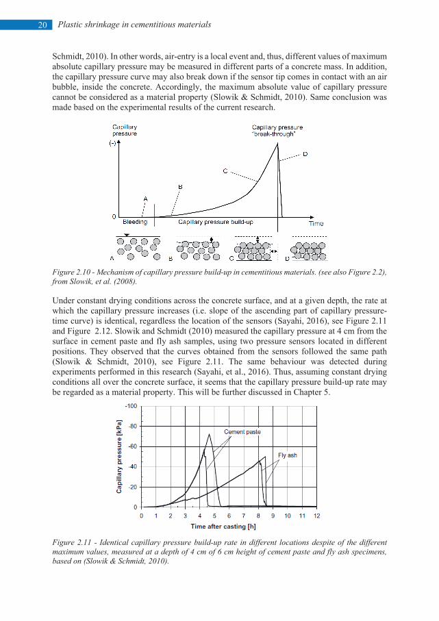
ργ ⋅⋅⋅×= − SP 7106.2 (2.8) where P = maximum absolute capillary pressure, [MPa], S = mass specific surface area of cement, [m2/kg], γ = surface tension of the pore liquid, [0.073 N/m for water], and, ρ = solid density of cement, [kg/m3]. Nevertheless, due to the irregularity of the solid particles arrangement in a concrete paste, the air-entry, see stage D in Figure 2.10, does not occur simultaneously in all pores (Slowik &
Plastic shrinkage in cementitious materials
20
Schmidt, 2010). In other words, air-entry is a local event and, thus, different values of maximum absolute capillary pressure may be measured in different parts of a concrete mass. In addition, the capillary pressure curve may also break down if the sensor tip comes in contact with an air bubble, inside the concrete. Accordingly, the maximum absolute value of capillary pressure cannot be considered as a material property (Slowik & Schmidt, 2010). Same conclusion was made based on the experimental results of the current research.
Figure 2.10 - Mechanism of capillary pressure build-up in cementitious materials. (see also Figure 2.2), from Slowik, et al. (2008). Under constant drying conditions across the concrete surface, and at a given depth, the rate at which the capillary pressure increases (i.e. slope of the ascending part of capillary pressure-time curve) is identical, regardless the location of the sensors (Sayahi, 2016), see Figure 2.11 and Figure 2.12. Slowik and Schmidt (2010) measured the capillary pressure at 4 cm from the surface in cement paste and fly ash samples, using two pressure sensors located in different positions. They observed that the curves obtained from the sensors followed the same path (Slowik & Schmidt, 2010), see Figure 2.11. The same behaviour was detected during experiments performed in this research (Sayahi, et al., 2016). Thus, assuming constant drying conditions all over the concrete surface, it seems that the capillary pressure build-up rate may be regarded as a material property. This will be further discussed in Chapter 5.
Figure 2.11 - Identical capillary pressure build-up rate in different locations despite of the different maximum values, measured at a depth of 4 cm of 6 cm height of cement paste and fly ash specimens, based on (Slowik & Schmidt, 2010).
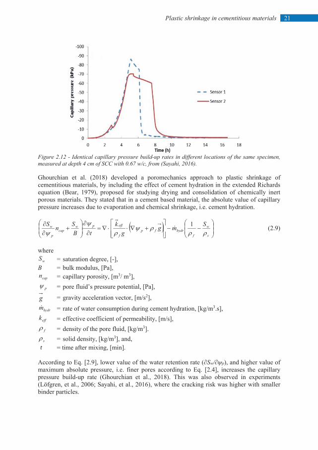
21 Plastic shrinkage in cementitious materials
Figure 2.12 - Identical capillary pressure build-up rates in different locations of the same specimen, measured at depth 4 cm of SCC with 0.67 w/c, from (Sayahi, 2016). Ghourchian et al. (2018) developed a poromechanics approach to plastic shrinkage of cementitious materials, by including the effect of cement hydration in the extended Richards equation (Bear, 1979), proposed for studying drying and consolidation of chemically inert porous materials. They stated that in a cement based material, the absolute value of capillary pressure increases due to evaporation and chemical shrinkage, i.e. cement hydration.
( )
−−
+∇⋅⋅∇=
∂∂
+
∂∂
s
w
fhydrfp
f
effpwcap
p
w Smgg
ktB
SnSρρ
ρψρ
ψψ
1 (2.9)
where
wS = saturation degree, [-], B = bulk modulus, [Pa],
capn = capillary porosity, [m3/ m3], pψ = pore fluid’s pressure potential, [Pa],
g = gravity acceleration vector, [m/s2],
hydrm = rate of water consumption during cement hydration, [kg/m3.s],
effk = effective coefficient of permeability, [m/s],
fρ = density of the pore fluid, [kg/m3].
sρ = solid density, [kg/m3], and, t = time after mixing, [min]. According to Eq. [2.9], lower value of the water retention rate (∂Sw/∂ѱp), and higher value of maximum absolute pressure, i.e. finer pores according to Eq. [2.4], increases the capillary pressure build-up rate (Ghourchian et al., 2018). This was also observed in experiments (Löfgren, et al., 2006; Sayahi, et al., 2016), where the cracking risk was higher with smaller binder particles.
Plastic shrinkage in cementitious materials
22
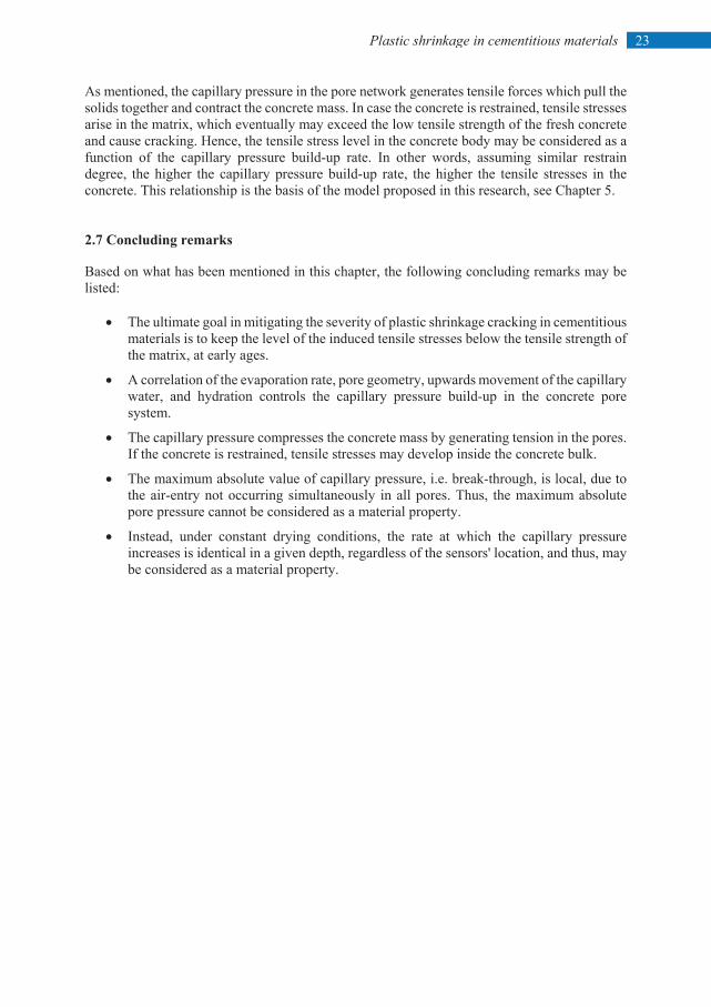
When evaporation rate is constant, evolution of capillary pressure accelerates, by faster stiffening and consolidation of the concrete (Radocea, 1994, Ghourchian, et al. 2018). Furthermore, as mentioned by Radocea (1992), the build-up of capillary pressure in concrete depends on the evaporation rate, pore geometry, and the amount of the water transferred towards the surface. 2.6 Tensile stress-strength relationship Another crucial parameter that plays a decisive role in plastic shrinkage cracking is the evolution of the fresh concrete tensile strength. Several experiments, e.g. (Kasai, et al., 1972; Hannant, et al., 1999; Branch, et al., 2002; Swaddiwudhipong, et al., 2003; Holt & Leivo, 2004; Dao, et al., 2009; Morris & Dux, 2010) have shown that the strain capacity of concrete reaches its lowest value around the initial setting time, see Figure 2.13. Also, other researchers have stated that the concrete tensile strength is very low between mixing and the time of initial setting, after which it starts to increase rapidly (Abel & Hover, 1998), due to the accelerated hydration and the consequent solidification of the concrete, see Figure 2.14.
Figure 2.13 - Tensile strain capacity of fresh concrete, based on Boshoff & Combrinck (2013).
Figure 2.14 - Tensile strength development for concrete mixes with 194 kg/m3 water content (in the legend, the numbers after WC and SL denote the w/c and the intended slump in inches, respectively), from (Abel & Hover, 1998).
0
0,1
0,2
0,3
0,4
0,5
0,6
0,7
0 1 2 3 4 5 6 7 8 9
Tens
ile st
reng
th (M
Pa)
Time after batching (h)
WC4SL1 WC5SL1 WC6SL1 WC7SL1
23 Plastic shrinkage in cementitious materials
As mentioned, the capillary pressure in the pore network generates tensile forces which pull the solids together and contract the concrete mass. In case the concrete is restrained, tensile stresses arise in the matrix, which eventually may exceed the low tensile strength of the fresh concrete and cause cracking. Hence, the tensile stress level in the concrete body may be considered as a function of the capillary pressure build-up rate. In other words, assuming similar restrain degree, the higher the capillary pressure build-up rate, the higher the tensile stresses in the concrete. This relationship is the basis of the model proposed in this research, see Chapter 5. 2.7 Concluding remarks Based on what has been mentioned in this chapter, the following concluding remarks may be listed:
• The ultimate goal in mitigating the severity of plastic shrinkage cracking in cementitious materials is to keep the level of the induced tensile stresses below the tensile strength of the matrix, at early ages.
• A correlation of the evaporation rate, pore geometry, upwards movement of the capillary water, and hydration controls the capillary pressure build-up in the concrete pore system.
• The capillary pressure compresses the concrete mass by generating tension in the pores. If the concrete is restrained, tensile stresses may develop inside the concrete bulk.
• The maximum absolute value of capillary pressure, i.e. break-through, is local, due to the air-entry not occurring simultaneously in all pores. Thus, the maximum absolute pore pressure cannot be considered as a material property.
• Instead, under constant drying conditions, the rate at which the capillary pressure increases is identical in a given depth, regardless of the sensors' location, and thus, may be considered as a material property.

25 Test methods and measuring techniques
3. TEST METHODS AND MEASURING TECHNIQUES This chapter presents complementary information about the test methods and the measuring techniques, used in this research. Also, comparison is made between the used test setups, where the pros and cons of each are highlighted. During the experiments in which measurement of the volumetric deformation was included, i.e. Papers II and III, a restrained specimen was cast alongside an unrestrained one, from the same patch, to ensure free deformation of the concrete, where the mass variation, capillary pressure, internal temperature development, and the volumetric shrinkage were measured. 3.1 Test methods 3.1.1 Restrained specimens In this particular research, the impact of the tested parameters on cracking was investigated using two different test setups, i.e. ASTM C 1579 (ASTM, 2006), and ring test method, also known as NORDTEST-method NT BUILD 433 (Johansen & Dahl, 1993). In addition another test setup, known as the rectangular mould, was utilized at the beginning of this PhD work. The results of the experiments performed using this setup, however, are not included in the appended papers. The mould will be briefly described in Section 3.1.1.3. The concretes in all moulds were restrained, and thus cracking was anticipated.
3.1.1.1 ASTM C1579 ASTM C 1579, see Figure 3.1 and Appendix A, is a test method developed mainly in order to compare the plastic shrinkage cracking behaviour of different concrete mixtures containing fibre reinforcement under "prescribed conditions of restraint and moisture loss that are severe enough to produce cracking before final setting of the concrete", according to (ASTM, 2006). Nevertheless, its application is not limited to only fibre reinforced concrete (FRC), and can be extended to include other parameters as well. This mould was used in Papers II and III, for studying the effect of admixtures and steel fibres on the cracking of plastic concrete. The mould was made of stainless steel. The stress riser in the middle acted as a crack initiation point, while the other two smaller metal inserts on the sides internally restrained the specimen. The interior sidewalls were coated with a thin layer of oil, in order to reduce the bond between the concrete and the mould. The experiments took place in a climate chamber to ensure constant ambient conditions (T = 20 ± 1˚C and RH = 30 ± 3%). A fan was located next to the mould to generate wind velocity of 8 ± 0.5 m/s across the concrete surface.
Test methods and measuring techniques
26
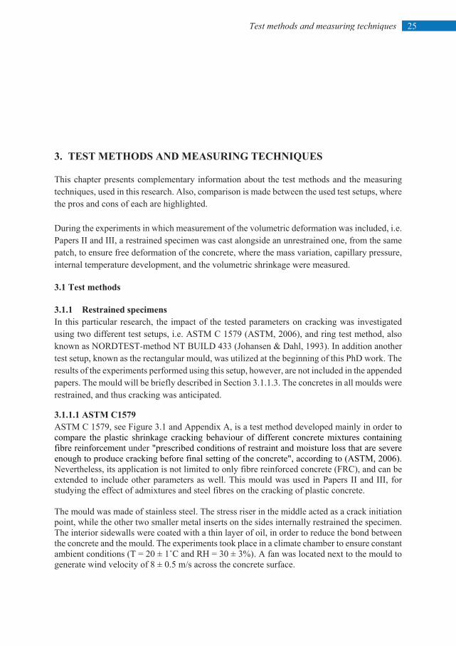
The cracking reduction ratio (CRR), which defines the percentage of reduction in the crack width in the FRC (ASTM, 2006), was calculated as follows:
1001 ×
−=
mixtureconcretecontrolofwidthcrackAverageFRCofwidthcrackAverageCRR (3.1)
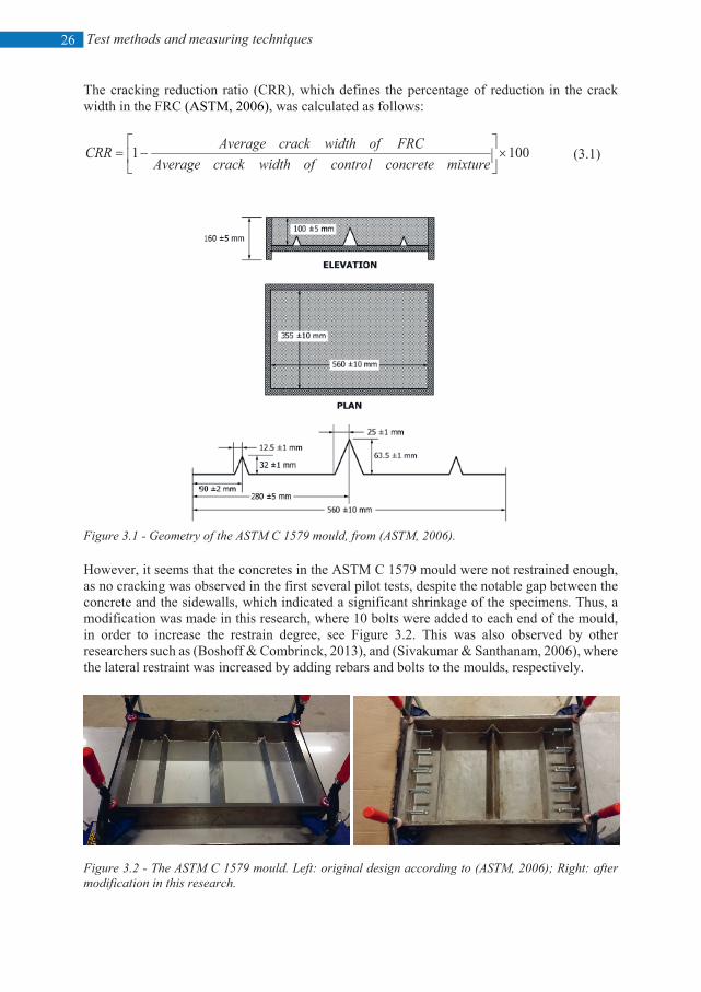
Figure 3.1 - Geometry of the ASTM C 1579 mould, from (ASTM, 2006). However, it seems that the concretes in the ASTM C 1579 mould were not restrained enough, as no cracking was observed in the first several pilot tests, despite the notable gap between the concrete and the sidewalls, which indicated a significant shrinkage of the specimens. Thus, a modification was made in this research, where 10 bolts were added to each end of the mould, in order to increase the restrain degree, see Figure 3.2. This was also observed by other researchers such as (Boshoff & Combrinck, 2013), and (Sivakumar & Santhanam, 2006), where the lateral restraint was increased by adding rebars and bolts to the moulds, respectively.
Figure 3.2 - The ASTM C 1579 mould. Left: original design according to (ASTM, 2006); Right: after modification in this research.
27 Test methods and measuring techniques
During the experiments, a heterogeneous airflow was detected across the concrete surfaces in the ASTM C 1579 mould, where the wind velocity close to the fan differed by around 0.5 m/s to 1.0 m/s from that on the other end. Another issue with the ASTM C 1579 mould is the CRR determining method, which according to Eq. [3.1], is based on the variation of the crack width, solely. However, it was observed that sometimes the crack length was also affected by the variables. Thus, in this research, both the crack width and the crack length were measured and the crack area was used in calculating the CRR. The crack location in the ASTM C 1579 mould is anticipated over the stress raiser in the middle, which makes the crack detection process easy.
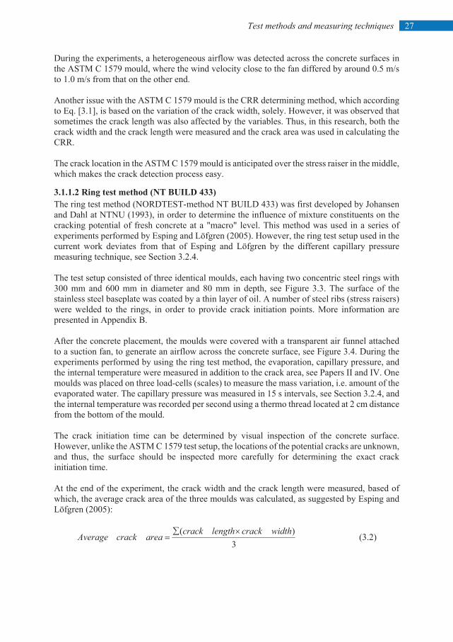
3.1.1.2 Ring test method (NT BUILD 433) The ring test method (NORDTEST-method NT BUILD 433) was first developed by Johansen and Dahl at NTNU (1993), in order to determine the influence of mixture constituents on the cracking potential of fresh concrete at a "macro" level. This method was used in a series of experiments performed by Esping and Löfgren (2005). However, the ring test setup used in the current work deviates from that of Esping and Löfgren by the different capillary pressure measuring technique, see Section 3.2.4. The test setup consisted of three identical moulds, each having two concentric steel rings with 300 mm and 600 mm in diameter and 80 mm in depth, see Figure 3.3. The surface of the stainless steel baseplate was coated by a thin layer of oil. A number of steel ribs (stress raisers) were welded to the rings, in order to provide crack initiation points. More information are presented in Appendix B. After the concrete placement, the moulds were covered with a transparent air funnel attached to a suction fan, to generate an airflow across the concrete surface, see Figure 3.4. During the experiments performed by using the ring test method, the evaporation, capillary pressure, and the internal temperature were measured in addition to the crack area, see Papers II and IV. One moulds was placed on three load-cells (scales) to measure the mass variation, i.e. amount of the evaporated water. The capillary pressure was measured in 15 s intervals, see Section 3.2.4, and the internal temperature was recorded per second using a thermo thread located at 2 cm distance from the bottom of the mould. The crack initiation time can be determined by visual inspection of the concrete surface. However, unlike the ASTM C 1579 test setup, the locations of the potential cracks are unknown, and thus, the surface should be inspected more carefully for determining the exact crack initiation time. At the end of the experiment, the crack width and the crack length were measured, based of which, the average crack area of the three moulds was calculated, as suggested by Esping and Löfgren (2005):
3)( widthcracklengthcrack
areacrackAverage×∑
= (3.2)
Test methods and measuring techniques
28
Figure 3.3 - Ring test setup for plastic shrinkage cracking tendency determination, based on Löfgren, et al. (2006) (dimensions in mm).
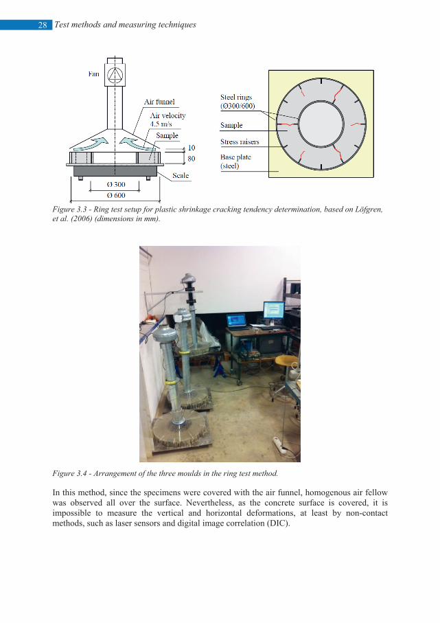
Figure 3.4 - Arrangement of the three moulds in the ring test method. In this method, since the specimens were covered with the air funnel, homogenous air fellow was observed all over the surface. Nevertheless, as the concrete surface is covered, it is impossible to measure the vertical and horizontal deformations, at least by non-contact methods, such as laser sensors and digital image correlation (DIC).
29 Test methods and measuring techniques
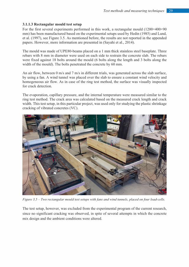
3.1.1.3 Rectangular mould test setup For the first several experiments performed in this work, a rectangular mould (1200×400×90 mm) has been manufactured based on the experimental setups used by Hedin (1985) and Lund, et al. (1997), see Figure 3.5. As mentioned before, the results are not reported in the appended papers. However, more information are presented in (Sayahi et al., 2014). The mould was made of UPE80-beams placed on a 1 mm thick stainless steel baseplate. Three rebars with 8 mm in diameter were used on each side to restrain the concrete slab. The rebars were fixed against 18 bolts around the mould (6 bolts along the length and 3 bolts along the width of the mould). The bolts penetrated the concrete by 60 mm. An air flow, between 0 m/s and 7 m/s in different trials, was generated across the slab surface, by using a fan. A wind tunnel was placed over the slab to ensure a constant wind velocity and homogeneous air flow. As in case of the ring test method, the surface was visually inspected for crack detection. The evaporation, capillary pressure, and the internal temperature were measured similar to the ring test method. The crack area was calculated based on the measured crack length and crack width. This test setup, in this particular project, was used only for studying the plastic shrinkage cracking of vibrated concretes (VC).
Figure 3.5 – Two rectangular mould test setups with fans and wind tunnels, placed on four load-cells. The test setup, however, was excluded from the experimental program of the current research, since no significant cracking was observed, in spite of several attempts in which the concrete mix design and the ambient conditions were altered.
Test methods and measuring techniques
30
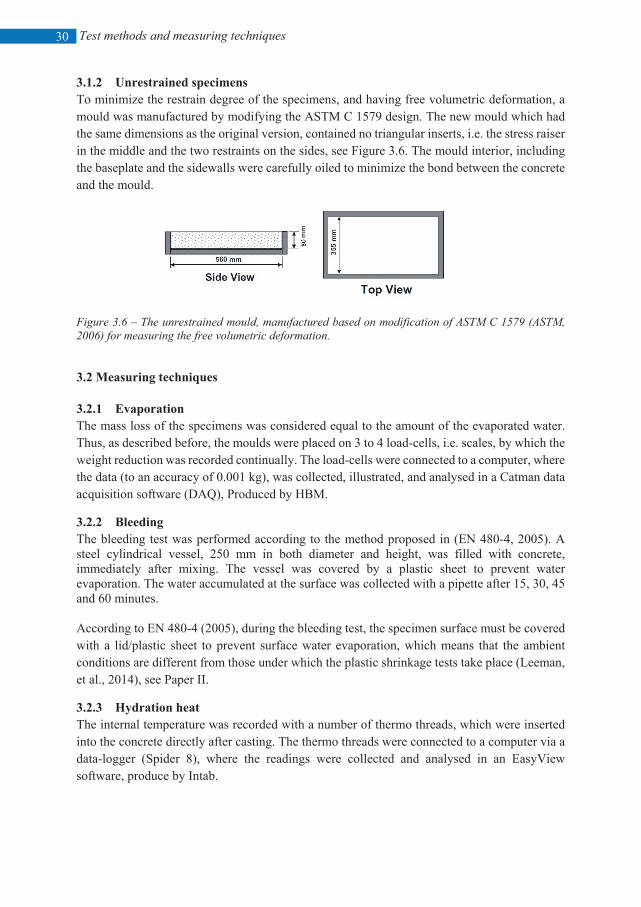
3.1.2 Unrestrained specimens To minimize the restrain degree of the specimens, and having free volumetric deformation, a mould was manufactured by modifying the ASTM C 1579 design. The new mould which had the same dimensions as the original version, contained no triangular inserts, i.e. the stress raiser in the middle and the two restraints on the sides, see Figure 3.6. The mould interior, including the baseplate and the sidewalls were carefully oiled to minimize the bond between the concrete and the mould.
Figure 3.6 – The unrestrained mould, manufactured based on modification of ASTM C 1579 (ASTM, 2006) for measuring the free volumetric deformation. 3.2 Measuring techniques 3.2.1 Evaporation The mass loss of the specimens was considered equal to the amount of the evaporated water. Thus, as described before, the moulds were placed on 3 to 4 load-cells, i.e. scales, by which the weight reduction was recorded continually. The load-cells were connected to a computer, where the data (to an accuracy of 0.001 kg), was collected, illustrated, and analysed in a Catman data acquisition software (DAQ), Produced by HBM.
3.2.2 Bleeding The bleeding test was performed according to the method proposed in (EN 480-4, 2005). A steel cylindrical vessel, 250 mm in both diameter and height, was filled with concrete, immediately after mixing. The vessel was covered by a plastic sheet to prevent water evaporation. The water accumulated at the surface was collected with a pipette after 15, 30, 45 and 60 minutes. According to EN 480-4 (2005), during the bleeding test, the specimen surface must be covered with a lid/plastic sheet to prevent surface water evaporation, which means that the ambient conditions are different from those under which the plastic shrinkage tests take place (Leeman, et al., 2014), see Paper II.
3.2.3 Hydration heat The internal temperature was recorded with a number of thermo threads, which were inserted into the concrete directly after casting. The thermo threads were connected to a computer via a data-logger (Spider 8), where the readings were collected and analysed in an EasyView software, produce by Intab.
31 Test methods and measuring techniques
3.2.4 Capillary pressure The capillary pressure was measured using Capillary Pressure Sensor System (CPSS), manufactured by Research and Transfer Centre (FTZ) at the Leipzig University of Applied Science (HTWK Leipzig), see Figure 3.7. The cone of the sensor should be filled with degased water and penetrate the concrete surface to a depth of around 4 - 5 cm. The system can measure the capillary pressure up to 100 kPa (to an accuracy of 0.01 kPa), in addition to the air temperature, the ambient RH, and the brightness (i.e. solar radiation). The sensors are wirelessly connected to a computer through a base station. The sending frequency is 2.4 GHz and the maximum radio transmission range is around 60 m. The collected data can be seen in real-time through a software installed on the computer. As mentioned in Section 3.1.1.2, the main deviation between the ring test setup used in this study with the one used by Esping and Löfgren (2006), is the capillary pressure measurement technique. Beside the different model (AB 0-15 PSIG from Data Instruments), in Esping and Löfgren's work, the sensors penetrated the concrete horizontally at depths of 2 cm and 6 cm from the concrete surface, whereas in the current study, the sensors were installed vertically to a depth of 4 cm.
Figure 3.7 – A sensor of CPSS, from (CPSS user manual). 3.2.5 Deformations In order to measure the horizontal deformations, i.e. shrinkage, of the specimens in the unrestrained mould (Section 3.1.2), two LVDTs were installed at the transversal ends of the mould, see Figure 3.8.
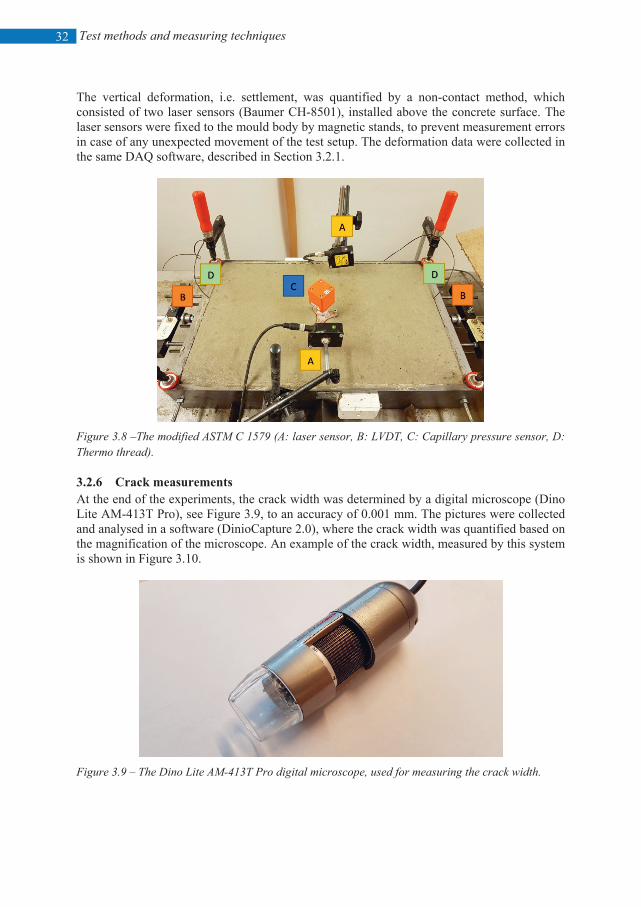
Test methods and measuring techniques
32
The vertical deformation, i.e. settlement, was quantified by a non-contact method, which consisted of two laser sensors (Baumer CH-8501), installed above the concrete surface. The laser sensors were fixed to the mould body by magnetic stands, to prevent measurement errors in case of any unexpected movement of the test setup. The deformation data were collected in the same DAQ software, described in Section 3.2.1.
Figure 3.8 –The modified ASTM C 1579 (A: laser sensor, B: LVDT, C: Capillary pressure sensor, D: Thermo thread). 3.2.6 Crack measurements At the end of the experiments, the crack width was determined by a digital microscope (Dino Lite AM-413T Pro), see Figure 3.9, to an accuracy of 0.001 mm. The pictures were collected and analysed in a software (DinioCapture 2.0), where the crack width was quantified based on the magnification of the microscope. An example of the crack width, measured by this system is shown in Figure 3.10.
Figure 3.9 – The Dino Lite AM-413T Pro digital microscope, used for measuring the crack width.
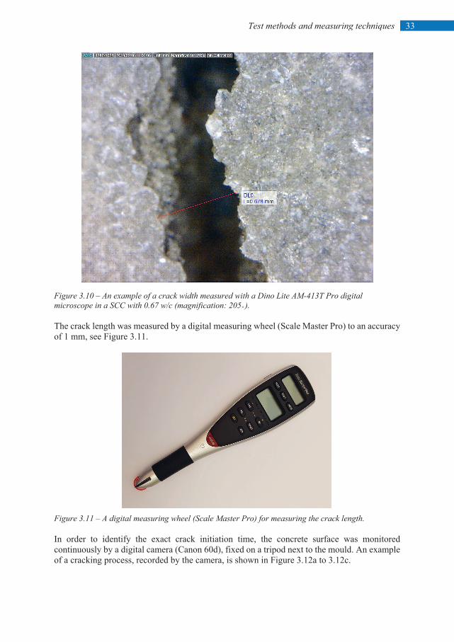
33 Test methods and measuring techniques
Figure 3.10 – An example of a crack width measured with a Dino Lite AM-413T Pro digital microscope in a SCC with 0.67 w/c (magnification: 205×). The crack length was measured by a digital measuring wheel (Scale Master Pro) to an accuracy of 1 mm, see Figure 3.11.
Figure 3.11 – A digital measuring wheel (Scale Master Pro) for measuring the crack length. In order to identify the exact crack initiation time, the concrete surface was monitored continuously by a digital camera (Canon 60d), fixed on a tripod next to the mould. An example of a cracking process, recorded by the camera, is shown in Figure 3.12a to 3.12c.
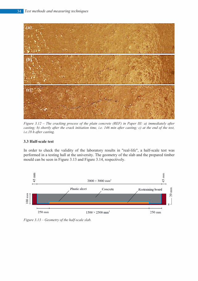
Test methods and measuring techniques
34
Figure 3.12 – The cracking process of the plain concrete (REF) in Paper III: a) immediately after casting; b) shortly after the crack initiation time, i.e. 146 min after casting; c) at the end of the test, i.e.18 h after casting. 3.3 Half-scale test In order to check the validity of the laboratory results in "real-life", a half-scale test was performed in a testing hall at the university. The geometry of the slab and the prepared timber mould can be seen in Figure 3.13 and Figure 3.14, respectively.
Figure 3.13 – Geometry of the half-scale slab.
(a)
(c)
(b)
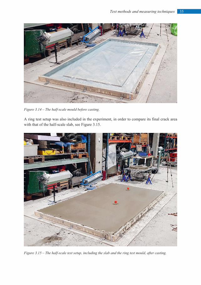
35 Test methods and measuring techniques
Figure 3.14 – The half-scale mould before casting. A ring test setup was also included in the experiment, in order to compare its final crack area with that of the half-scale slab, see Figure 3.15.
Figure 3.15 – The half-scale test setup, including the slab and the ring test mould, after casting.
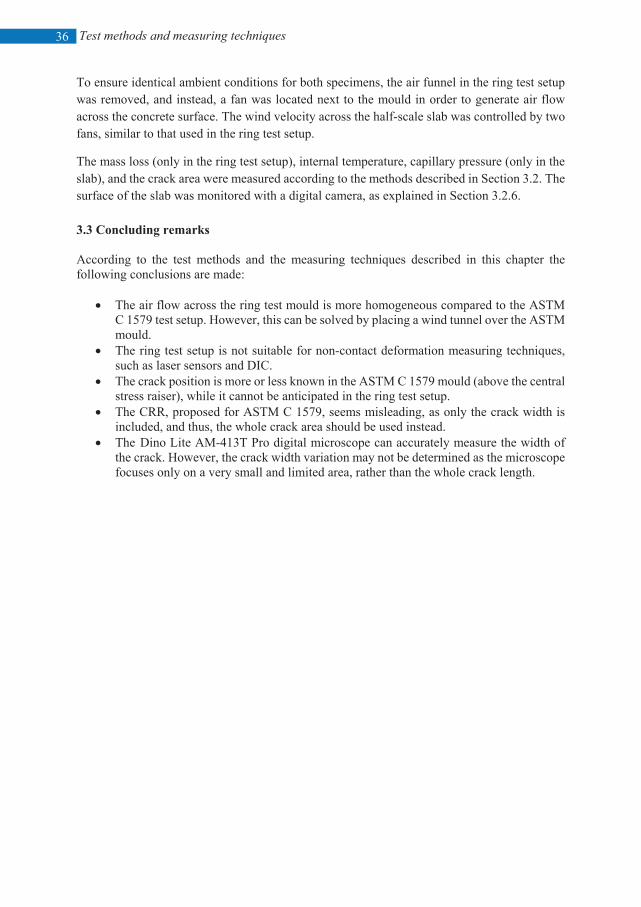
Test methods and measuring techniques
36
To ensure identical ambient conditions for both specimens, the air funnel in the ring test setup was removed, and instead, a fan was located next to the mould in order to generate air flow across the concrete surface. The wind velocity across the half-scale slab was controlled by two fans, similar to that used in the ring test setup.
The mass loss (only in the ring test setup), internal temperature, capillary pressure (only in the slab), and the crack area were measured according to the methods described in Section 3.2. The surface of the slab was monitored with a digital camera, as explained in Section 3.2.6. 3.3 Concluding remarks According to the test methods and the measuring techniques described in this chapter the following conclusions are made:
• The air flow across the ring test mould is more homogeneous compared to the ASTM C 1579 test setup. However, this can be solved by placing a wind tunnel over the ASTM mould.
• The ring test setup is not suitable for non-contact deformation measuring techniques, such as laser sensors and DIC.
• The crack position is more or less known in the ASTM C 1579 mould (above the central stress raiser), while it cannot be anticipated in the ring test setup.
• The CRR, proposed for ASTM C 1579, seems misleading, as only the crack width is included, and thus, the whole crack area should be used instead.
• The Dino Lite AM-413T Pro digital microscope can accurately measure the width of the crack. However, the crack width variation may not be determined as the microscope focuses only on a very small and limited area, rather than the whole crack length.
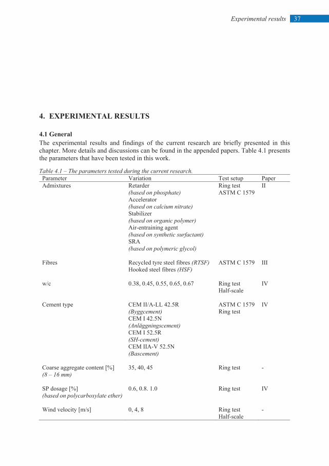
37 Experimental results
4. EXPERIMENTAL RESULTS 4.1 General The experimental results and findings of the current research are briefly presented in this chapter. More details and discussions can be found in the appended papers. Table 4.1 presents the parameters that have been tested in this work.
Table 4.1 – The parameters tested during the current research. Parameter Variation Test setup Paper Admixtures Retarder
(based on phosphate) Accelerator (based on calcium nitrate) Stabilizer (based on organic polymer) Air-entraining agent (based on synthetic surfactant) SRA (based on polymeric glycol)
Ring test ASTM C 1579
II
Fibres Recycled tyre steel fibres (RTSF) Hooked steel fibres (HSF)
ASTM C 1579 III
w/c 0.38, 0.45, 0.55, 0.65, 0.67
Ring test Half-scale
IV
Cement type CEM II/A-LL 42.5R (Byggcement) CEM I 42.5N (Anläggningscement) CEM I 52.5R (SH-cement) CEM IIA-V 52.5N (Bascement)
ASTM C 1579 Ring test
IV
Coarse aggregate content [%] (8 – 16 mm)
35, 40, 45
Ring test -
SP dosage [%] (based on polycarboxylate ether)
0.6, 0.8. 1.0
Ring test
IV
Wind velocity [m/s] 0, 4, 8 Ring test Half-scale
-
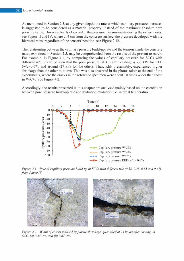
Experimental results
38
As mentioned in Section 2.5, at any given depth, the rate at which capillary pressure increases is suggested to be considered as a material property, instead of the maximum absolute pore pressure value. This was clearly observed in the pressure measurements during the experiments, see Papers II and IV, where at 4 cm from the concrete surface, the pressure developed with the identical rates, regardless of the sensors' position, see Figure 2.12. The relationship between the capillary pressure build-up rate and the tension inside the concrete mass, explained in Section 2.5, may be comprehended from the results of the present research. For example, in Figure 4.1, by comparing the values of capillary pressure for SCCs with different w/c, it can be seen that the pore pressure, at 4 h after casting, is -38 kPa for REF (w/c=0.67), and around -27 kPa for the others. Thus, REF presumably, experienced higher shrinkage than the other mixtures. This was also observed in the photos taken at the end of the experiments, where the cracks in the reference specimen were about 10 times wider than those in W/C45, see Figure 4.2. Accordingly, the results presented in this chapter are analysed mainly based on the correlation between pore pressure build-up rate and hydration evolution, i.e. internal temperature.
Figure 4.1 – Rete of capillary pressure build-up in SCCs with different w/c (0.38, 0.45, 0.55 and 0.67), from Paper IV.
Figure 4.2 – Width of cracks induced by plastic shrinkage, quantified at 24 hours after casting, in SCC, (a) 0.45 w/c, and (b) 0.67 w/c.
-100-90-80-70-60-50-40-30-20-10
00 2 4 6 8 10 12 14 16 18
Cap
illar
y pr
essu
re (k
Pa)
Time (h)
Capillary pressure W/C38Capillary pressure W/C45Capillary pressure W/C55Capillary pressure REF (w/c = 0.67)
(a) (b)
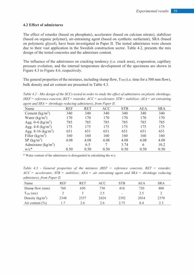
39 Experimental results
4.2 Effect of admixtures The effect of retarder (based on phosphate), accelerator (based on calcium nitrate), stabilizer (based on organic polymer), air-entraining agent (based on synthetic surfactant), SRA (based on polymeric glycol), have been investigated in Paper II. The tested admixtures were chosen due to their vast application in the Swedish construction sector. Table 4.2, presents the mix design of the tested concretes and the admixture content. The influence of the admixtures on cracking tendency (i.e. crack area), evaporation, capillary pressure evolution, and the internal temperature development of the specimens are shown in Figure 4.3 to Figure 4.6, respectively. The general properties of the mixtures, including slump flow, T500 (i.e. time for a 500 mm flow), bulk density and air content are presented in Table 4.3. Table 4.2 - Mix design of the SCCs tested in order to study the effect of admixtures on plastic shrinkage, (REF = reference concrete, RET = retarder, ACC = accelerator, STB = stabilizer, AEA = air entraining agent and SRA = shrinkage reducing admixture), from Paper II. Name REF RET ACC STB AEA SRA Cement (kg/m3) 340 340 340 340 340 340 Water (kg/m3) 170 170 170 170 170 170 Agg. 0-4 (kg/m3) 785 785 785 785 785 785 Agg. 4-8 (kg/m3) 175 175 175 175 175 175 Agg. 8-16 (kg/m3) 651 651 651 651 651 651 Filler (kg/m3) 160 160 160 160 160 160 SP (kg/m3) 4.08 4.08 4.08 4.08 4.08 4.08 Admixture (kg/m3) - 6.5 7 3.74 6 10.2 w/c* 0.50 0.50 0.50 0.50 0.50 0.50
* Water content of the admixtures is disregarded in calculating the w/c. Table 4.3 - General properties of the mixtures (REF = reference concrete, RET = retarder, ACC = accelerator, STB = stabilizer, AEA = air entraining agent and SRA = shrinkage reducing admixture), from Paper II. Name REF RET ACC STB AEA SRA Slump flow (mm) 760 650 730 410 720 800 T500 (sec) 2 3 2.5 - 2.5 2 Density (kg/m3) 2348 2357 2424 2392 2034 2370 Air content (%) 1.7 2.6 2.6 2.75 8.4 2.3
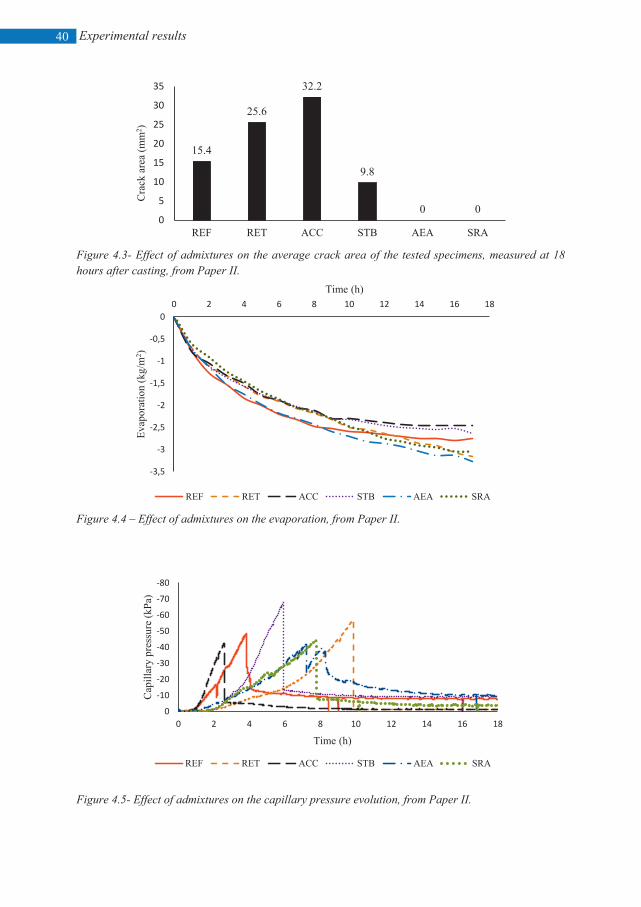
Experimental results
40
Figure 4.3- Effect of admixtures on the average crack area of the tested specimens, measured at 18 hours after casting, from Paper II.
Figure 4.4 – Effect of admixtures on the evaporation, from Paper II.
Figure 4.5- Effect of admixtures on the capillary pressure evolution, from Paper II.
15.4
25.6
32.2
9.8
0 00
5
10
15
20
25
30
35
REF RET ACC STB AEA SRA
Cra
ck a
rea
(mm
2 )
-3,5
-3
-2,5
-2
-1,5
-1
-0,5
00 2 4 6 8 10 12 14 16 18
Evap
orat
ion
(kg/
m2 )
Time (h)
REF RET ACC STB AEA SRA
-80
-70
-60
-50
-40
-30
-20
-10
00 2 4 6 8 10 12 14 16 18
Cap
illar
y pr
essu
re (k
Pa)
Time (h)
REF RET ACC STB AEA SRA
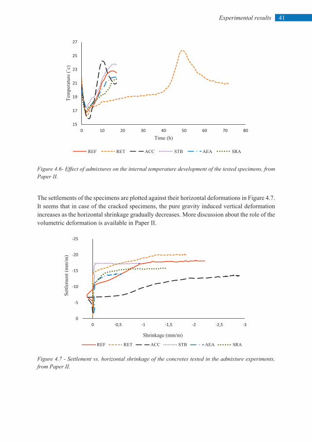
41 Experimental results
Figure 4.6- Effect of admixtures on the internal temperature development of the tested specimens, from Paper II.
The settlements of the specimens are plotted against their horizontal deformations in Figure 4.7. It seems that in case of the cracked specimens, the pure gravity induced vertical deformation increases as the horizontal shrinkage gradually decreases. More discussion about the role of the volumetric deformation is available in Paper II.
Figure 4.7 - Settlement vs. horizontal shrinkage of the concretes tested in the admixture experiments, from Paper II.
15
17
19
21
23
25
27
0 10 20 30 40 50 60 70 80
Tem
pera
ture
(˚c)
Time (h)
REF RET ACC STB AEA SRA
-25
-20
-15
-10
-5
0-3-2,5-2-1,5-1-0,50
Settl
emen
t (m
m/m
)
Shrinkage (mm/m)
REF RET ACC STB AEA SRA
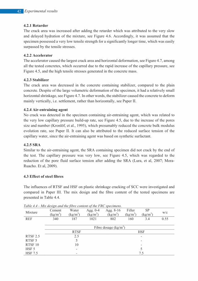
Experimental results
42
4.2.1 Retarder The crack area was increased after adding the retarder which was attributed to the very slow and delayed hydration of the mixture, see Figure 4.6. Accordingly, it was assumed that the specimen possessed a very low tensile strength for a significantly longer time, which was easily surpassed by the tensile stresses.
4.2.2 Accelerator The accelerator caused the largest crack area and horizontal deformation, see Figure 4.7, among all the tested concretes, which occurred due to the rapid increase of the capillary pressure, see Figure 4.5, and the high tensile stresses generated in the concrete mass.
4.2.3 Stabilizer The crack area was decreased in the concrete containing stabilizer, compared to the plain concrete. Despite of the large volumetric deformation of the specimen, it had a relatively small horizontal shrinkage, see Figure 4.7. In other words, the stabilizer caused the concrete to deform mainly vertically, i.e. settlement, rather than horizontally, see Paper II.
4.2.4 Air-entraining agent No crack was detected in the specimen containing air-entraining agent, which was related to the very low capillary pressure build-up rate, see Figure 4.5, due to the increase of the pores size and number (Kronlöf, et al., 1995), which presumably reduced the concrete bulk modulus evolution rate, see Paper II. It can also be attributed to the reduced surface tension of the capillary water, since the air-entraining agent was based on synthetic surfactant.
4.2.5 SRA Similar to the air-entraining agent, the SRA containing specimen did not crack by the end of the test. The capillary pressure was very low, see Figure 4.5, which was regarded to the reduction of the pore fluid surface tension after adding the SRA (Lura, et al, 2007; Mora-Ruacho. Et al, 2009). 4.3 Effect of steel fibres The influences of RTSF and HSF on plastic shrinkage cracking of SCC were investigated and compared in Paper III. The mix design and the fibre content of the tested specimens are presented in Table 4.4.
Table 4.4 - Mix design and the fibre content of the FRC specimens.
Mixture Cement (kg/m3)
Water (kg/m3)
Agg. 0-4 (kg/m3)
Agg. 8-16 (kg/m3)
Filler (kg/m3)
SP (kg/m3) w/c
REF 340 187 1021 802 160 3.4 0.55 Fibre dosage (kg/m3) RTSF HSF
RTSF 2.5 2.5 - RTSF 5 5 - RTSF 10 10 - HSF 5 - 5 HSF 7.5 - 7.5
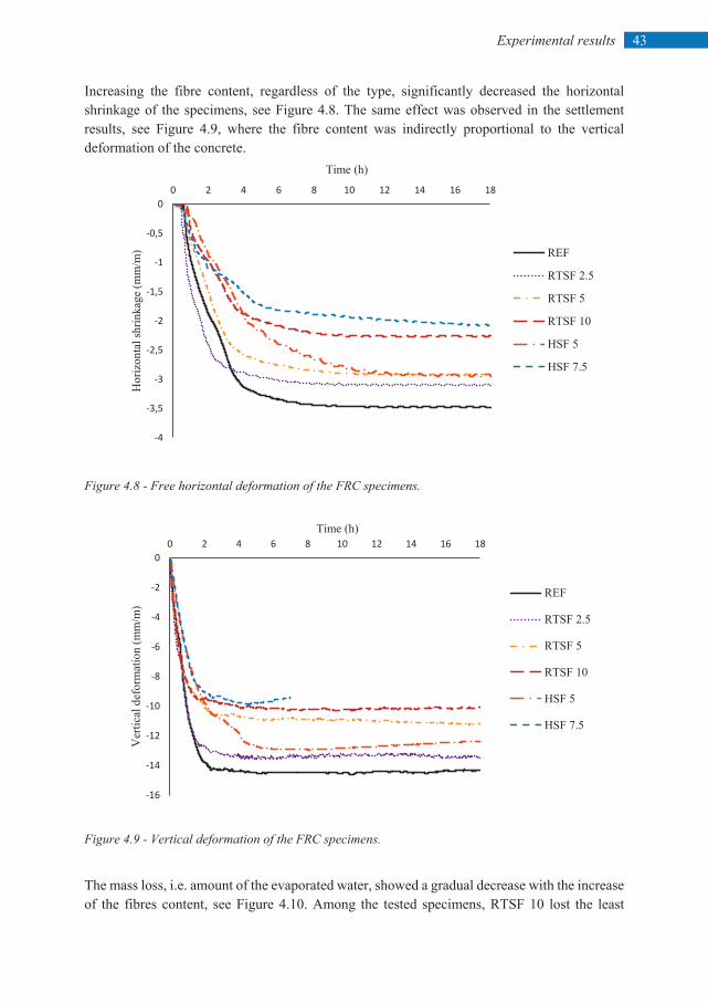
43 Experimental results
Increasing the fibre content, regardless of the type, significantly decreased the horizontal shrinkage of the specimens, see Figure 4.8. The same effect was observed in the settlement results, see Figure 4.9, where the fibre content was indirectly proportional to the vertical deformation of the concrete.
Figure 4.8 - Free horizontal deformation of the FRC specimens.
Figure 4.9 - Vertical deformation of the FRC specimens.
The mass loss, i.e. amount of the evaporated water, showed a gradual decrease with the increase of the fibres content, see Figure 4.10. Among the tested specimens, RTSF 10 lost the least
-4
-3,5
-3
-2,5
-2
-1,5
-1
-0,5
00 2 4 6 8 10 12 14 16 18
Hor
izon
tal s
hrin
kage
(mm
/m)
Time (h)
REF
RTSF 2.5
RTSF 5
RTSF 10
HSF 5
HSF 7.5
-16
-14
-12
-10
-8
-6
-4
-2
00 2 4 6 8 10 12 14 16 18
Ver
tical
def
orm
atio
n (m
m/m
)
Time (h)
REF
RTSF 2.5
RTSF 5
RTSF 10
HSF 5
HSF 7.5
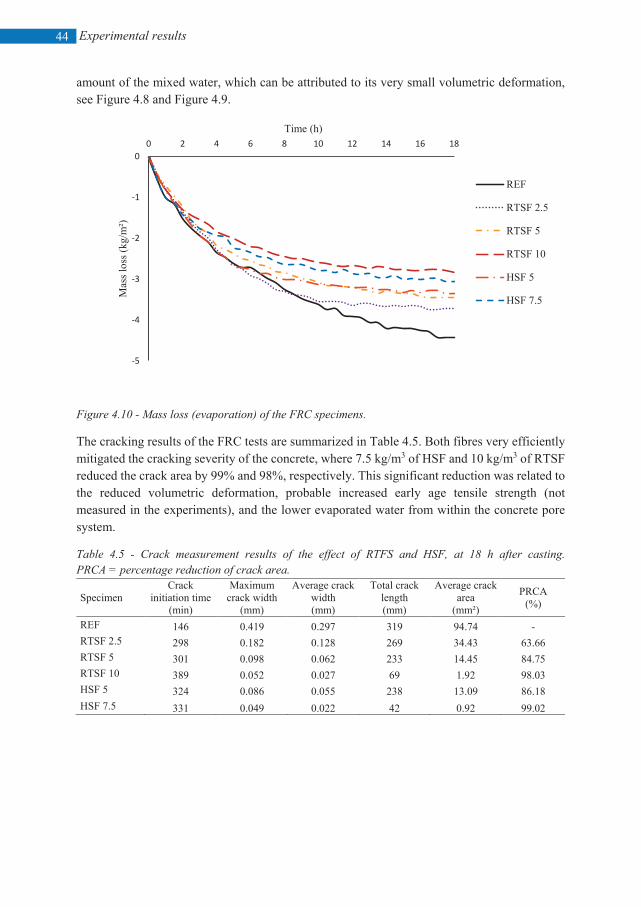
Experimental results
44
amount of the mixed water, which can be attributed to its very small volumetric deformation, see Figure 4.8 and Figure 4.9.
Figure 4.10 - Mass loss (evaporation) of the FRC specimens.
The cracking results of the FRC tests are summarized in Table 4.5. Both fibres very efficiently mitigated the cracking severity of the concrete, where 7.5 kg/m3 of HSF and 10 kg/m3 of RTSF reduced the crack area by 99% and 98%, respectively. This significant reduction was related to the reduced volumetric deformation, probable increased early age tensile strength (not measured in the experiments), and the lower evaporated water from within the concrete pore system.
Table 4.5 - Crack measurement results of the effect of RTFS and HSF, at 18 h after casting. PRCA = percentage reduction of crack area.
Specimen Crack
initiation time (min)
Maximum crack width
(mm)
Average crack width (mm)
Total crack length (mm)
Average crack area
(mm²)
PRCA (%)
REF 146 0.419 0.297 319 94.74 - RTSF 2.5 298 0.182 0.128 269 34.43 63.66 RTSF 5 301 0.098 0.062 233 14.45 84.75 RTSF 10 389 0.052 0.027 69 1.92 98.03 HSF 5 324 0.086 0.055 238 13.09 86.18 HSF 7.5 331 0.049 0.022 42 0.92 99.02
-5
-4
-3
-2
-1
00 2 4 6 8 10 12 14 16 18
Mas
s los
s (kg
/m²)
Time (h)
REF
RTSF 2.5
RTSF 5
RTSF 10
HSF 5
HSF 7.5
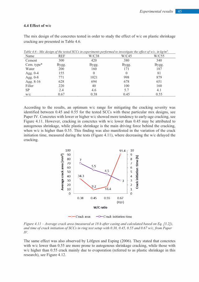
45 Experimental results
4.4 Effect of w/c The mix design of the concretes tested in order to study the effect of w/c on plastic shrinkage cracking are presented in Table 4.6. Table 4.6 - Mix design of the tested SCCs in experiments performed to investigate the effect of w/c, in kg/m3. Name REF W/C38 W/C45 W/C55 Cement 300 420 380 340 Cem. type* Bygg. Bygg. Bygg. Bygg. Water 200 160 171 187 Agg. 0-4 155 0 0 81 Agg. 0-8 771 1021 998 879 Agg. 8-16 628 694 678 651 Filler 220 40 100 160 SP 2.4 4.6 5.7 4.1 w/c 0.67 0.38 0.45 0.55
According to the results, an optimum w/c range for mitigating the cracking severity was identified between 0.45 and 0.55 for the tested SCCs with these particular mix designs, see Paper IV. Concretes with lower or higher w/c showed more tendency to early-age cracking, see Figure 4.11. However, cracking in concretes with w/c lower than 0.45 may be attributed to autogenous shrinkage, while plastic shrinkage is the main driving force behind the cracking, when w/c is higher than 0.55. This finding was also manifested in the variation of the crack initiation time, measured during the tests (Figure 4.11), where decreasing the w/c delayed the cracking.
Figure 4.11 – Average crack area (measured at 18 h after casing and calculated based on Eq. [3.2]), and time of crack initiation of SCCs in ring test setup with 0.38, 0.45, 0.55 and 0.67 w/c, from Paper IV. The same effect was also observed by Löfgren and Esping (2006). They stated that concretes with w/c lower than 0.55 are more prone to autogenous shrinkage cracking, while those with w/c higher than 0.55 crack mainly due to evaporation (referred to as plastic shrinkage in this research), see Figure 4.12.
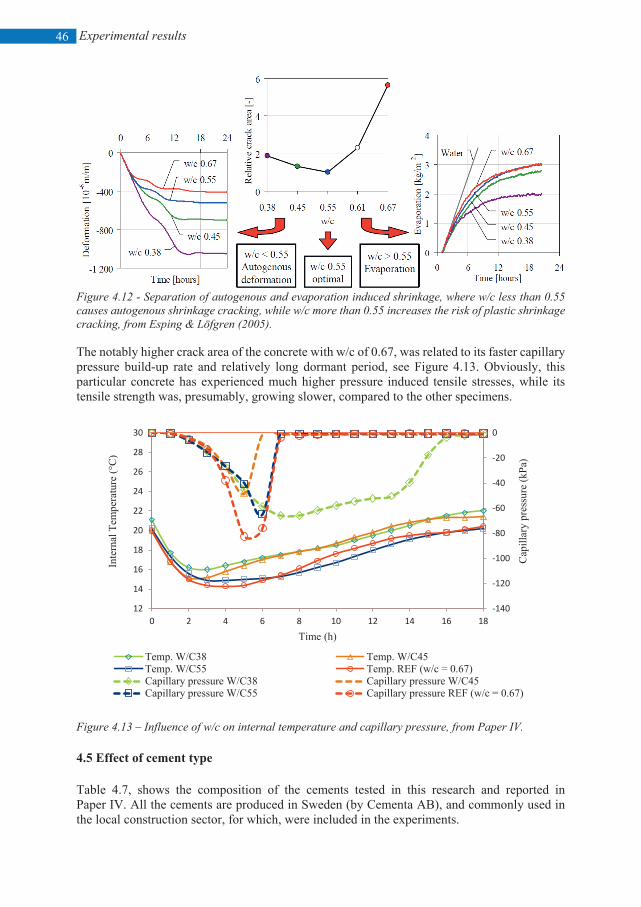
Experimental results
46
Figure 4.12 - Separation of autogenous and evaporation induced shrinkage, where w/c less than 0.55 causes autogenous shrinkage cracking, while w/c more than 0.55 increases the risk of plastic shrinkage cracking, from Esping & Löfgren (2005). The notably higher crack area of the concrete with w/c of 0.67, was related to its faster capillary pressure build-up rate and relatively long dormant period, see Figure 4.13. Obviously, this particular concrete has experienced much higher pressure induced tensile stresses, while its tensile strength was, presumably, growing slower, compared to the other specimens.
Figure 4.13 – Influence of w/c on internal temperature and capillary pressure, from Paper IV. 4.5 Effect of cement type Table 4.7, shows the composition of the cements tested in this research and reported in Paper IV. All the cements are produced in Sweden (by Cementa AB), and commonly used in the local construction sector, for which, were included in the experiments.
-140
-120
-100
-80
-60
-40
-20
0
12
14
16
18
20
22
24
26
28
30
0 2 4 6 8 10 12 14 16 18
Cap
illar
y pr
essu
re (k
Pa)
Inte
rnal
Tem
pera
ture
(°C
)
Time (h)
Temp. W/C38 Temp. W/C45Temp. W/C55 Temp. REF (w/c = 0.67)Capillary pressure W/C38 Capillary pressure W/C45Capillary pressure W/C55 Capillary pressure REF (w/c = 0.67)
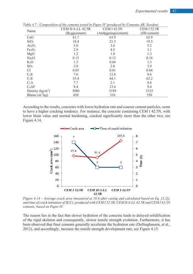
47 Experimental results
Table 4.7 - Composition of the cements tested in Paper IV (produced by Cementa AB, Sweden). Name CEM II/A-LL 42.5R
(Byggcement) CEM I 42.5N
(Anläggningscement) CEM I 52.5R (SH-cement)
CaO 61.7 63.9 62.9 SiO2 18.4 21.3 19.3 Al2O3 5.0 3.6 5.2 Fe2O3 2.9 4.5 3.1 MgO 1.2 1.0 1.3 Na2O 0.15 0.12 0.16 K2O 1.3 0.66 1.3 SO3 3.8 2.8 3.9 CI 0.03 0.01 0.04 C2S 7.6 12.8 8.6 C3S 55.4 64.1 62.2 C3A 7.7 2.1 8.6 C4AF 8.4 13.6 9.4 Density (kg/m3) 3080 3189 3125 Blaine (m2/kg) 430 310 550
According to the results, concretes with lower hydration rate and coarser cement particles, seem to have a higher cracking tendency. For instance, the concrete containing CEM I 42.5N, with lower blain value and normal hardening, cracked significantly more than the other two, see Figure 4.14.
Figure 4.14 – Average crack area (measured at 18 h after casing and calculated based on Eq. [3.2]), and time of crack initiation of SCCs, produced with CEM I 52.5R, CEM II/A-LL 42.5R and CEM I 42.5N cements, based on Paper IV.
The reason lies in the fact that slower hydration of the concrete leads to delayed solidification of the rigid skeleton and consequently, slower tensile strength evolution. Furthermore, it has been observed that finer cements generally accelerate the hydration rate (Dellinghausen, et al., 2012), and accordingly, increase the tensile strength development rate, see Figure 4.15.
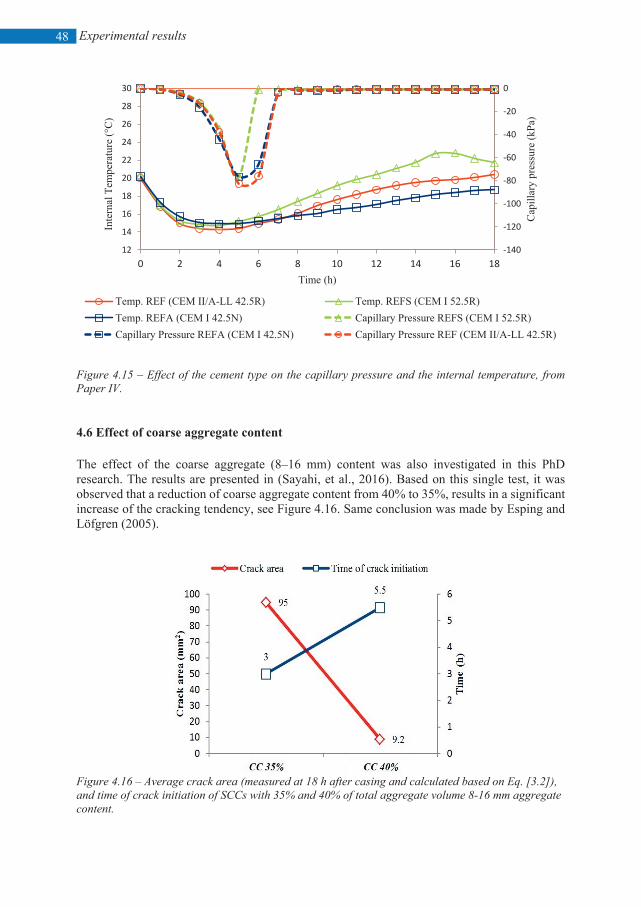
Experimental results
48
Figure 4.15 – Effect of the cement type on the capillary pressure and the internal temperature, from Paper IV. 4.6 Effect of coarse aggregate content The effect of the coarse aggregate (8–16 mm) content was also investigated in this PhD research. The results are presented in (Sayahi, et al., 2016). Based on this single test, it was observed that a reduction of coarse aggregate content from 40% to 35%, results in a significant increase of the cracking tendency, see Figure 4.16. Same conclusion was made by Esping and Löfgren (2005).
Figure 4.16 – Average crack area (measured at 18 h after casing and calculated based on Eq. [3.2]), and time of crack initiation of SCCs with 35% and 40% of total aggregate volume 8-16 mm aggregate content.
-140
-120
-100
-80
-60
-40
-20
0
12
14
16
18
20
22
24
26
28
30
0 2 4 6 8 10 12 14 16 18
Cap
illar
y pr
essu
re (k
Pa)
Inte
rnal
Tem
pera
ture
(°C
)
Time (h)
Temp. REF (CEM II/A-LL 42.5R) Temp. REFS (CEM I 52.5R)Temp. REFA (CEM I 42.5N) Capillary Pressure REFS (CEM I 52.5R)Capillary Pressure REFA (CEM I 42.5N) Capillary Pressure REF (CEM II/A-LL 42.5R)
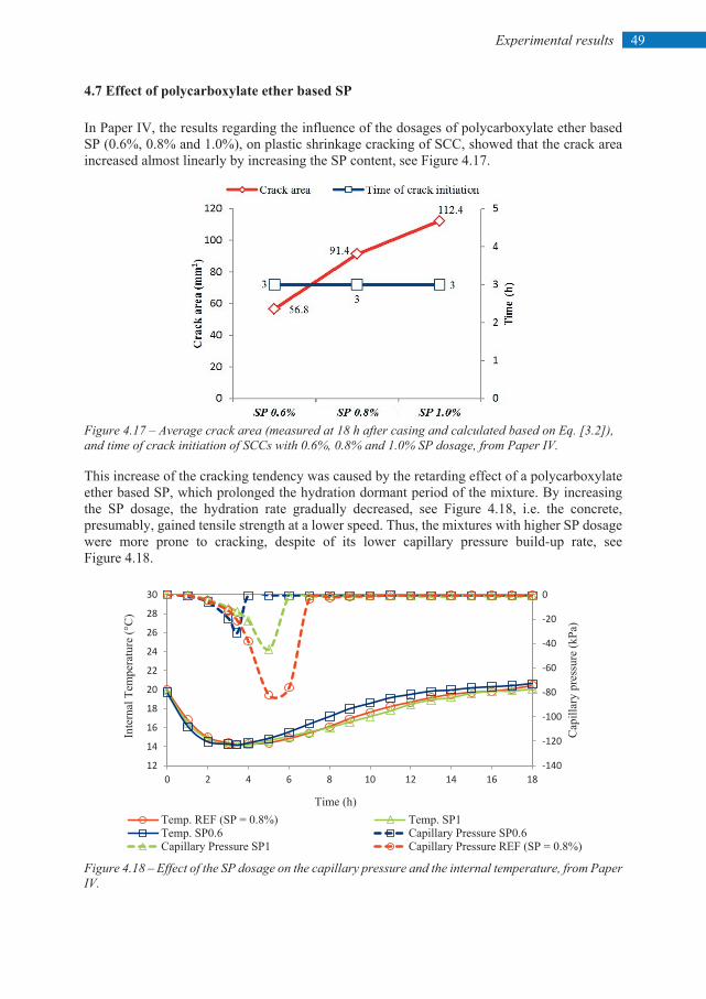
49 Experimental results
4.7 Effect of polycarboxylate ether based SP In Paper IV, the results regarding the influence of the dosages of polycarboxylate ether based SP (0.6%, 0.8% and 1.0%), on plastic shrinkage cracking of SCC, showed that the crack area increased almost linearly by increasing the SP content, see Figure 4.17.
Figure 4.17 – Average crack area (measured at 18 h after casing and calculated based on Eq. [3.2]), and time of crack initiation of SCCs with 0.6%, 0.8% and 1.0% SP dosage, from Paper IV. This increase of the cracking tendency was caused by the retarding effect of a polycarboxylate ether based SP, which prolonged the hydration dormant period of the mixture. By increasing the SP dosage, the hydration rate gradually decreased, see Figure 4.18, i.e. the concrete, presumably, gained tensile strength at a lower speed. Thus, the mixtures with higher SP dosage were more prone to cracking, despite of its lower capillary pressure build-up rate, see Figure 4.18.
Figure 4.18 – Effect of the SP dosage on the capillary pressure and the internal temperature, from Paper IV.
-140
-120
-100
-80
-60
-40
-20
0
12
14
16
18
20
22
24
26
28
30
0 2 4 6 8 10 12 14 16 18
Cap
illar
y pr
essu
re (k
Pa)
Inte
rnal
Tem
pera
ture
(°C
)
Time (h)Temp. REF (SP = 0.8%) Temp. SP1Temp. SP0.6 Capillary Pressure SP0.6Capillary Pressure SP1 Capillary Pressure REF (SP = 0.8%)
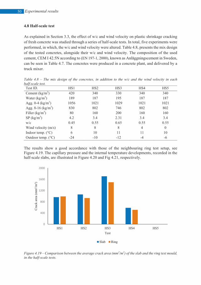
Experimental results
50
4.8 Half-scale test As explained in Section 3.3, the effect of w/c and wind velocity on plastic shrinkage cracking of fresh concrete was studied through a series of half-scale tests. In total, five experiments were performed, in which, the w/c and wind velocity were altered. Table 4.8, presents the mix design of the tested concretes, alongside their w/c and wind velocity. The composition of the used cement, CEM I 42.5N according to (EN 197-1, 2000), known as Anläggningscement in Sweden, can be seen in Table 4.7. The concretes were produced in a concrete plant, and delivered by a truck mixer. Table 4.8 – The mix design of the concretes, in addition to the w/c and the wind velocity in each half-scale test. Test ID. HS1 HS2 HS3 HS4 HS5 Cement (kg/m3) 420 340 330 340 340 Water (kg/m3) 189 187 195 187 187 Agg. 0-4 (kg/m3) 1056 1021 1029 1021 1021 Agg. 8-16 (kg/m3) 830 802 746 802 802 Filler (kg/m3) 80 160 200 160 160 SP (kg/m3) 4.2 3.4 2.31 3.4 3.4 w/c 0.45 0.55 0.65 0.55 0.55 Wind velocity (m/s) 8 8 8 4 0 Indoor temp. (°C) 6 10 11 11 10 Outdoor temp. (°C) -24 -10 -12 -4 -6
The results show a good accordance with those of the neighbouring ring test setup, see Figure 4.19. The capillary pressure and the internal temperature developments, recorded in the half-scale slabs, are illustrated in Figure 4.20 and Fig 4.21, respectively.
Figure 4.19 – Comparison between the average crack area (mm2/m2) of the slab and the ring test mould, in the half-scale tests.
0
400
800
1200
1600
2000
HS1 HS2 HS3 HS4 HS5
Cra
ck a
rea
(mm
²/m²)
Test
Slab Ring
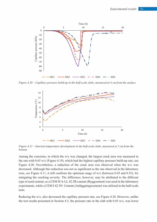
51 Experimental results
Figure 4.20 – Capillary pressure build-up in the half-scale slabs, measured at 4 cm from the surface.
Figure 4.21 – Internal temperature development in the half-scale slabs, measured at 2 cm from the bottom.
Among the concretes, in which the w/c was changed, the largest crack area was measured in the one with 0.65 w/c (Figure 4.19), which had the highest capillary pressure build-up rate, see Figure 4.20. Nevertheless, a reduction of the crack area was observed when the w/c was decreased. Although this reduction was not as significant as the one observed in the laboratory tests, see Figure 4.11, it still confirms the optimum range of w/c (between 0.45 and 0.55), for mitigating the cracking severity. The difference, however, may be attributed to the different type of used cement, as a CEM II/A-LL 42.5R cement (Byggcement) was used in the laboratory experiments, while a CEM I 42.5N Cement (Anläggningscement) was utilized in the half-scale tests.
Reducing the w/c, also decreased the capillary pressure rate, see Figure 4.20. However, unlike the test results presented in Section 4.5, the pressure rate in the slab with 0.45 w/c, was lower
-90
-80
-70
-60
-50
-40
-30
-20
-10
00 5 10 15 20
Cap
illar
y pr
essu
re (k
Pa)
Time (h)
HS1 HS2 HS3 HS4 HS5
0
2
4
6
8
10
12
14
0 5 10 15 20
Tem
pera
ture
(°C
)
Time (h)
HS1 HS2 HS3 HS4 HS5
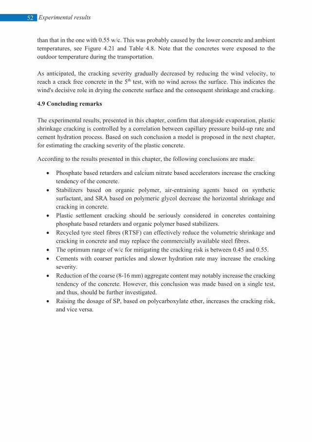
Experimental results
52
than that in the one with 0.55 w/c. This was probably caused by the lower concrete and ambient temperatures, see Figure 4.21 and Table 4.8. Note that the concretes were exposed to the outdoor temperature during the transportation. As anticipated, the cracking severity gradually decreased by reducing the wind velocity, to reach a crack free concrete in the 5th test, with no wind across the surface. This indicates the wind's decisive role in drying the concrete surface and the consequent shrinkage and cracking.
4.9 Concluding remarks The experimental results, presented in this chapter, confirm that alongside evaporation, plastic shrinkage cracking is controlled by a correlation between capillary pressure build-up rate and cement hydration process. Based on such conclusion a model is proposed in the next chapter, for estimating the cracking severity of the plastic concrete.
According to the results presented in this chapter, the following conclusions are made:
• Phosphate based retarders and calcium nitrate based accelerators increase the cracking tendency of the concrete.
• Stabilizers based on organic polymer, air-entraining agents based on synthetic surfactant, and SRA based on polymeric glycol decrease the horizontal shrinkage and cracking in concrete.
• Plastic settlement cracking should be seriously considered in concretes containing phosphate based retarders and organic polymer based stabilizers.
• Recycled tyre steel fibres (RTSF) can effectively reduce the volumetric shrinkage and cracking in concrete and may replace the commercially available steel fibres.
• The optimum range of w/c for mitigating the cracking risk is between 0.45 and 0.55. • Cements with coarser particles and slower hydration rate may increase the cracking
severity. • Reduction of the coarse (8-16 mm) aggregate content may notably increase the cracking
tendency of the concrete. However, this conclusion was made based on a single test, and thus, should be further investigated.
• Raising the dosage of SP, based on polycarboxylate ether, increases the cracking risk, and vice versa.
53 Cracking severity model
5 CRACKING SEVERITY MODEL 5.1 Introduction This chapter briefly describes a model proposed based on the findings of the current research, to estimate the severity of plastic shrinkage cracking in cementations materials. As mentioned earlier, cracking occurs when the tensile stresses, induced by the capillary pressure, exceed the tensile strength of the mixture. The proposed model is thus, based on the tensile stress-strength relationship of the fresh concrete. The tensile stresses in a concrete member, if restrained, are directly proportional to the level of the capillary pressure. However, since the maximum absolute pressure value in a single point cannot be generalized to the whole concrete bulk, it may not be used for determination of the tensile stresses level in the concrete. Instead, as suggested before, under constant drying conditions, the capillary pressure build-up rate may be considered as a material property, and hence, can indicate the level of tensile stresses in the concrete mass, see Sections 2.5 and 4.1. Further discussion is available in Papers IV and V. It must be remarked that the last sentence is true only if the restrain degree is constant. It is known that the capillary pressure generates tensile stresses, only if the concrete is restrained (internally and/or externally). Otherwise, if the member can deform freely, no stresses will develop inside the concrete mass, and thus, no cracking will occur. It means that in case of difference in the restrain degree, a partly restrained concrete elements with even a high capillary pressure build-up rate may show less cracking tendency, compared to a fully restrained one with a lower pressure rate. The autogenous shrinkage is neglected in the proposed model, and it is assumed that the concrete cracks due to plastic shrinkage, solely. However, the effect of hydration is incorporated in the bleeding reduction due to loss of intrinsic permeability brought by the chemical reactions between cement and water. Accordingly the assumptions of the new model are: a) the concretes are equally restrained, and b) the autogenous shrinkage is not part of the cracking process. The new model relates the cracking severity of plastic cementitious materials to the capillary pressure build-up rate (not the absolute value), drying time, and the initial setting time. For simplification, the pore pressure evolution rate is replaced by the rate at which water evaporates from within the concrete. The model may be used as a tool for estimating/comparing the
Cracking severity model
54
cracking risk of concretes prior to casting, in order to identify the one with the least cracking tendency. Thus, several assumptions were made in order to simplify the model that led to the current version. Nevertheless, a more detailed and sophisticated version may be developed in future. 5.2 Model formulation The tensile strain capacity of the concrete reaches its lowest value at around the initial setting time (around the end of the hydration dormant period), see Section 2.6. Also, as mentioned earlier, development of early-age tensile strength of the concrete is consistent with the degree of hydration. Hence, it can be assumed that the initial setting time is equal to the length of the period during which the concrete is highly prone to tensile stresses. The drying time of concrete is reached when all the bleed water, accumulated at the surface, has dried out. In such case, the concrete enters the drying phase, where water menisci form at the uppermost surface, and the pore liquid starts to evaporate. This point is the beginning of the capillary pressure build-up in the pores, which in turn generates tensile stresses in the restrained concrete. The drying time may be used as an indication of the cracking risk based on the tensile stress-strength ratio. The period between the drying time and the initial set of the concrete is referred to as critical period, tcr, in this research, see Figure 5.1. It is assumed that the longer the critical period, the higher the cracking risk and vice versa. The critical period can be determined as: tcr = tini – td (5.1) and t = td when 1=
BE (5.2)
where tcr = critical period, [h], t = time from mixing, [h], tini = initial setting time, [h], td = drying time, [h], E = amount of the evaporated water, [kg/m2], and, B = amount of the bleed water, [kg/m2]. It is known that the period between the drying time and the final set, provides the time needed for crack initiation and propagation (Ghourchian, et al., 2017). However, since the hydration rate after the initial set (i.e. the rate of tensile strength evolution), differs based on the mix design and the ambient conditions, in this model, tini is set as the upper limit of the critical period, where the tensile strength is meagre, regardless of the concrete type. The following similarity is then proposed under the assumption that the cracking severity increases with a faster capillary pressure build-up, in addition to longer critical period and delayed initial set.
)(~ diniinis ttdtdPtC −×× (5.3)
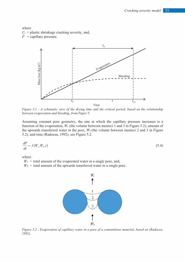
55 Cracking severity model
where Cs = plastic shrinkage cracking severity, and, P = capillary pressure.
Figure 5.1 - A schematic view of the drying time and the critical period, based on the relationship between evaporation and bleeding, from Paper V. Assuming constant pore geometry, the rate at which the capillary pressure increases is a function of the evaporation, We (the volume between menisci 1 and 3 in Figure 5.2), amount of the upwards transferred water in the pore, Wb (the volume between menisci 2 and 3 in Figure 5.2), and time (Radocea, 1992), see Figure 5.2.
),,( tWWfdtdP
be= (5.4)
where We = total amount of the evaporated water in a single pore, and, Wb = total amount of the upwards transferred water in a single pore.
Figure 5.2 - Evaporation of capillary water in a pore of a cementitious material, based on (Radocea, 1992).
Mas
s los
s (kg
/m2 )
Time
Bleeding
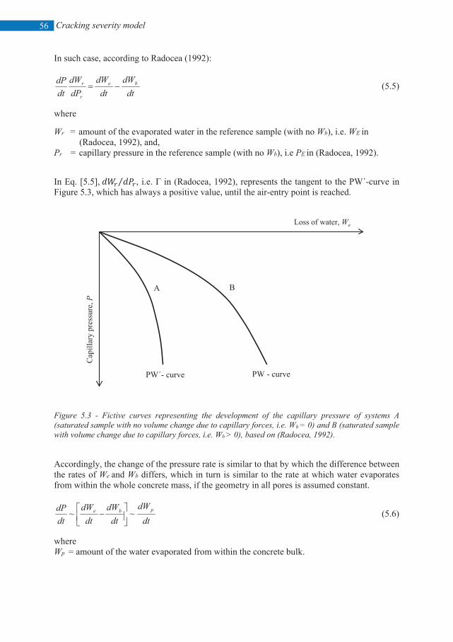
Cracking severity model
56
In such case, according to Radocea (1992):
dtdW
dtdW
dPdW
dtdP be
r
r −= (5.5)
where
Wr = amount of the evaporated water in the reference sample (with no Wb), i.e. WE in (Radocea, 1992), and,
Pr = capillary pressure in the reference sample (with no Wb), i.e PE in (Radocea, 1992).
In Eq. [5.5], 𝑑𝑑𝑑𝑑𝑟𝑟 𝑑𝑑𝑑𝑑𝑟𝑟⁄ , i.e. Γ in (Radocea, 1992), represents the tangent to the PW΄-curve in Figure 5.3, which has always a positive value, until the air-entry point is reached.
Figure 5.3 - Fictive curves representing the development of the capillary pressure of systems A (saturated sample with no volume change due to capillary forces, i.e. Wb = 0) and B (saturated sample with volume change due to capillary forces, i.e. Wb > 0), based on (Radocea, 1992). Accordingly, the change of the pressure rate is similar to that by which the difference between the rates of We and Wb differs, which in turn is similar to the rate at which water evaporates from within the whole concrete mass, if the geometry in all pores is assumed constant.
dtdW
dtdW
dtdW
dtdP pbe ~~
− (5.6)
where Wp = amount of the water evaporated from within the concrete bulk.
Cap
illar
y pr
essu
re, P
Loss of water, We
PW΄- curve PW - curve
A B
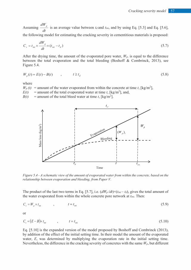
57 Cracking severity model
Assuming dt
dWp is an average value between td and tini, and by using Eq. [5.3] and Eq. [5.6],
the following model for estimating the cracking severity in cementitious materials is proposed:
)( dinip
inis ttdt
dWtC −××= (5.7)
After the drying time, the amount of the evaporated pore water, Wp, is equal to the difference between the total evaporation and the total bleeding (Boshoff & Combrinck, 2013), see Figure 5.4.
)()()( tBtEtWp −= , dtt ≥ (5.8)
where Wp (t) = amount of the water evaporated from within the concrete at time t, [kg/m2], E(t) = amount of the total evaporated water at time t, [kg/m2], and, B(t) = amount of the total bleed water at time t, [kg/m2].
Figure 5.4 - A schematic view of the amount of evaporated water from within the concrete, based on the relationship between evaporation and bleeding, from Paper V. The product of the last two terms in Eq. [5.7], i.e. (dWp /dt)×(tini – td), gives the total amount of the water evaporated from within the whole concrete pore network at tini. Then:
inips tWC ×= , initt = (5.9)
or
( ) inis tBEC ×−= , initt = (5.10)
Eq. [5.10] is the expanded version of the model proposed by Boshoff and Combrinck (2013), by addition of the effect of the initial setting time. In their model the amount of the evaporated water, E, was determined by multiplying the evaporation rate in the initial setting time. Nevertheless, the difference in the cracking severity of concretes with the same Wp, but different
Mas
s los
s (kg
/m2 )
Time
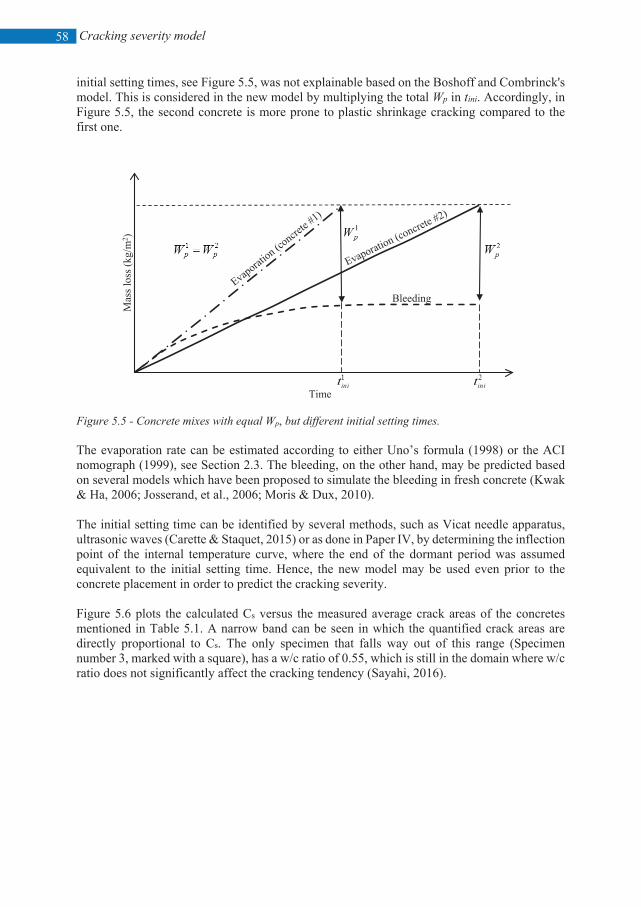
Cracking severity model
58
initial setting times, see Figure 5.5, was not explainable based on the Boshoff and Combrinck's model. This is considered in the new model by multiplying the total Wp in tini. Accordingly, in Figure 5.5, the second concrete is more prone to plastic shrinkage cracking compared to the first one.
Figure 5.5 - Concrete mixes with equal Wp, but different initial setting times.
The evaporation rate can be estimated according to either Uno’s formula (1998) or the ACI nomograph (1999), see Section 2.3. The bleeding, on the other hand, may be predicted based on several models which have been proposed to simulate the bleeding in fresh concrete (Kwak & Ha, 2006; Josserand, et al., 2006; Moris & Dux, 2010). The initial setting time can be identified by several methods, such as Vicat needle apparatus, ultrasonic waves (Carette & Staquet, 2015) or as done in Paper IV, by determining the inflection point of the internal temperature curve, where the end of the dormant period was assumed equivalent to the initial setting time. Hence, the new model may be used even prior to the concrete placement in order to predict the cracking severity. Figure 5.6 plots the calculated Cs versus the measured average crack areas of the concretes mentioned in Table 5.1. A narrow band can be seen in which the quantified crack areas are directly proportional to Cs. The only specimen that falls way out of this range (Specimen number 3, marked with a square), has a w/c ratio of 0.55, which is still in the domain where w/c ratio does not significantly affect the cracking tendency (Sayahi, 2016).
Mas
s los
s (kg
/m2 )
Time
Bleeding
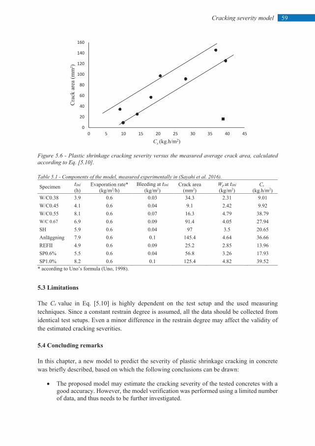
59 Cracking severity model
Figure 5.6 - Plastic shrinkage cracking severity versus the measured average crack area, calculated according to Eq. [5.10]. Table 5.1 - Components of the model, measured experimentally in (Sayahi et al. 2016).
Specimen tini (h)
Evaporation rate* (kg/m2/h)
Bleeding at tini (kg/m2)
Crack area (mm2)
Wp at tini (kg/m2)
Cs (kg.h/m2)
W/C0.38 3.9 0.6 0.03 34.3 2.31 9.01 W/C0.45 4.1 0.6 0.04 9.1 2.42 9.92 W/C0.55 8.1 0.6 0.07 16.3 4.79 38.79 W/C 0.67 6.9 0.6 0.09 91.4 4.05 27.94 SH 5.9 0.6 0.04 97 3.5 20.65 Anläggning 7.9 0.6 0.1 145.4 4.64 36.66 REFII 4.9 0.6 0.09 25.2 2.85 13.96 SP0.6% 5.5 0.6 0.04 56.8 3.26 17.93 SP1.0% 8.2 0.6 0.1 125.4 4.82 39.52
* according to Uno’s formula (Uno, 1998). 5.3 Limitations The Cs value in Eq. [5.10] is highly dependent on the test setup and the used measuring techniques. Since a constant restrain degree is assumed, all the data should be collected from identical test setups. Even a minor difference in the restrain degree may affect the validity of the estimated cracking severities. 5.4 Concluding remarks In this chapter, a new model to predict the severity of plastic shrinkage cracking in concrete was briefly described, based on which the following conclusions can be drawn:
• The proposed model may estimate the cracking severity of the tested concretes with a good accuracy. However, the model verification was performed using a limited number of data, and thus needs to be further investigated.
0
20
40
60
80
100
120
140
160
0 5 10 15 20 25 30 35 40 45
Cra
ck a
rea
(mm
²)
Cs (kg.h/m2)

Cracking severity model
60
• The model is applicable regardless the concrete type, e.g. SCC and VC. • The model should be utilized for estimating the cracking severity of equally restrained
concretes. • The cracking severity may be reduced by decreasing the evaporation rate, increasing the
bleeding capacity and accelerating the initial setting of the concrete.

61 Discussion and general conclusion
6 DISCUSSION AND GENERAL CONCLUSIONS 6.1 Discussion As stated, the hypothesis of this research was that a complex correlation between evaporation, capillary pressure, and cement hydration, is the driving force behind plastic shrinkage in cementitious materials. During the literature study, it was noted that there are many cracking events that may not be fully explained, only based on the evaporation. For instance, sometimes, heavily cracked concretes show an evaporation close to those with much lower cracking tendency, see for example the effect of w/c in (Esping & Löfgren, 2005) and Paper IV. Accordingly, the first idea was that there must be another way to explain the cracking severity in cementitious materials, which eventually, was found to be a correlation between capillary pressure and hydration rates. Although the effect of the pore pressure on the tensile strength in the concrete bulk, and the accordance of the tensile strength development with the cement hydration, has been known to the research community for a long time, it was noted that the focus is mainly on the pressure value, rather than its rate. Despite the fact that the air-entry value is completely local in a concrete mass, it was found that the rate at which the pressure increases at any given depth is identical. This was observed in all experiments performed in the present study, without exception. Hence, assuming constant restrain degree, the capillary pressure build-up rate may reveal the level of tensile stresses experienced by the concrete element. Accordingly, in this research, the absolute value of capillary pressure was considered of less importance, and instead, the role of its build-up rate was investigated. Assuming similar drying conditions, the pressure rate was suggested to be regarded as a material property, and has been used in formulation the model proposed in Paper V. The similarity between the pressure rates measured at the same depth of one specimen was also observed by Slowik and Schmidt (2010). The rate of pore pressure evolution, still cannot explain the cracking severity, if the cement hydration is disregarded, see for example (Leeman et al., 2014), where the concrete with lower pressure rate cracked more than the reference, and vice versa. More examples can be found in the experimental results of the present study, see effect of RET and SP in Papers II and IV, respectively. As the tensile strength of the concrete is meagre between mixing and the initial set (Abel & Hover, 1998), it was found that the cracking severity of plastic cement based materials, is directly proportional to the rate at which capillary pressure increases (representing the tensile stress development), and the initial setting time (representing the time-span during which the
Discussion and general conclusion
62
tensile strength is very low). This statement agrees with the alleged relationship between evaporation, capillary pressure, and hydration, which formed the research hypothesis. The validity of this relationship was confirmed through results of several laboratory and half-scale tests, performed by author. For instance, ACC which had the largest crack area, also had the fastest capillary pressure increase, see Figure 4.5, among the other specimens. The high pressure rate, presumably, increased the tensile stresses in the concrete bulk to a level, far beyond the low early-age tensile strength of the concrete. Hence, the concrete experienced the most intensive cracking, which could be more, if the hydration of the mixture was slower, see Figure 4.6.
In case of the influence of the SP dosage, the concrete containing the highest amount of SP showed the highest cracking tendency, see Figure 4.17, despite of its lowest pressure and hydration rates among the other specimens, see Figure 4.18, which indicates that the cracking severity of the concrete is affected by the pressure rate and the hydration process combined, and not individually. Another example is the effect of cements on plastic shrinkage cracking, where they had minor impact on the capillary pressure rate, see Figure 4.15. In such case it is assumed that the cracking was mainly controlled by the hydration rate, where REFA (CEM I 42.5N), possessing the longest dormant period, see Figure 4.15, cracked notably more than the other two concretes, see Figure 4.14. The slightly increased crack area in the REFS, compared to the reference mixture, was regarded partly to autogenous shrinkage, due to its fast hydration. Based on the defined correlation between the pressure and the hydration rates, it is expected to have higher cracking severity in a concrete with rapid pressure increase compared to one with lower rate, if the initial set is constant. This was observed in the results of the experiments performed in order to investigate the impact of w/c on cracking, where two specimens (i.e. REF and W/C55), had more or less equal dormant period, i.e. initial setting time. However, the reference concrete with the w/c of 0.67, possessed faster pressure development, see Figure 4.13, and consequently, significantly higher crack area, see Figure 4.11. The same effect of w/c on cracking was also observed by other researchers (Esping & Löfgren, 2005). Accordingly, it seems that the research hypothesis is confirmed by the discussed pressure-hydration relationship, based on which a new model for estimating the severity of plastic shrinkage cracking was proposed. The model was checked and validated, using experimental data reported by the author and other researchers (Ghourchian et al., 2018; Maritz, 2012), see Paper V. The role of vertical and horizontal deformations was also investigated in this research. The process of volumetric shrinkage was explained based on the drying process of porous materials (Brinker & Scherer, 1990; Lura, et al., 2007). By studying the influence of the tested admixtures on the volumetric deformation of concrete, it was noticed that the settlement and horizontal shrinkage of the cracked specimens are indirectly proportional. In other words, some admixtures, such as phosphate based retarders and organic polymer based stabilizers, caused significant vertical deformation and small horizontal shrinkage, and thus, should be protected against plastic settlement cracking, if vertically restrained.
63 Discussion and general conclusion
On the other hand, settlement probably is not the main cracking reason in concretes with calcium nitrate based accelerators, where a notable horizontal shrinkage occurred. Thus, in this research, the settlement-shrinkage ratio was defined, by which the dominant cracking mechanism in concrete may be identified, see Paper II. It should be mentioned that in Paper III, the impact of the steel fibres on the cracking was not discussed based on the pressure-hydration relationship, since an external factor (i.e. fibre) has probably boosted the tensile strength of the fresh concrete (Banthia, Yan, 2000; Ramakrishnan, 2001). Accordingly, it was not possible to estimate the early-age tensile strength of the specimens based on the hydration rate, solely. Thus, the effect of fibres on the concrete tensile strength at such an early-age needs to be more investigated. Considering the outcomes of this research, general recommendations for mitigating the risk of plastic shrinkage cracking in concrete, which may provide guidelines for the construction industry, are listed below:
• If it is possible, concrete should not be cast under warm, arid, and windy ambient conditions.
• The evaporation should remain as low as possible through, for example, covering the concrete surface by a plastic sheet, using wind breaker, and/or protecting the concrete surface from strong sunshine.
• The amount of the evaporated water should be compensated by re-wetting the surface, e.g. fogging.
• Vertically restrained concretes may crack due to plastic settlement, e.g. above rebars, which may further develop and widen due to horizontal shrinkage. Thus, large vertical deformations of the concrete may be controlled by, for instance, adding admixtures, such as SRA.
• Fibres (steel fibres in this case) may be added to the mixture, in order to reduce the cracking risk.
• It is recommended to have a w/c between 0.45 and 0.55. • Compared to VC, extra precautions should be taken in regard to SCC, and high
performance concretes containing a large amount of fines. Based to the results and findings of the current study, the research questions may be answered: RQ1 – Is water evaporation really the main reason behind plastic shrinkage cracking of young
concrete? Answer:
Yes, moisture loss primary in form of water evaporation is the main cause of plastic shrinkage in cement based materials. It is true that mixtures with higher evaporation probably crack more than those with lower amount of evaporated water. However, the cracking severity may not be explained only based on the evaporation. Instead the rate of capillary pressure build-up and the hydration process (i.e. initial setting time) should be considered.
Discussion and general conclusion
64
RQ2 – What is the role of capillary pressure and hydration rates in the cracking process? Answer:
Instead of the maximum absolute capillary pressure value, which is a local event, its build-up rate may be assumed as a material property, under constant drying conditions. Thus, in a restrained member, the pressure rate is directly proportional to the level of the tensile stresses in the mixture. On the other hand, the tensile strength of cementitious materials is meagre during the period between mixing and the initial set, after which it increases rapidly. Accordingly, the hydration process of a mixture may reveal its tensile strength development. Hence, a combination of the pore pressure build-up rate and the hydration speed may explain the cracking severity of the plastic cement based materials.
RQ3 – In which way are vertical and horizontal deformations involved in plastic shrinkage
cracking? Answer:
Vertical deformation due to gravitational acceleration is the cause of the water accumulation at the concrete surface, i.e. bleeding. Horizontal shrinkage on the other hand, starts when capillary pressure begins to increase in the pore system, i.e. drying regime. The pore water still moves upward in this period, but never reaches the surface. Thus, as long as the pores are saturated, the volumetric deformation of concrete is in a good agreement with the amount of the evaporated water. Vertical deformation may cause settlement cracking (if the element is vertically restrained, e.g. above rebars), which may develop further by the horizontal shrinkage. Hence, knowing the volumetric shrinkage of the concrete is crucial in choosing the proper crack mitigating method.
RQ4 – Can the effects of parameters related to mix design be graded and quantified individually.
Answer:
Concrete is a complex of interconnected constituents that need to be quantified in a way to ensure the integrity of the mixture and avoid segregation. Thus, it is very difficult to change the amount of a component of the mix design individually, without modifying the others. This is more pronounced in regard to for example, w/c, fine content, etc. Even changing the material type, e.g. using different admixtures, by maintaining constant portion in the mix design, may not give the actual effect of that particular parameter, since for example, the water content of the admixtures may alter the total w/c of the mixture.
RQ5 – Is it possible to model the phenomenon in a proper way based on the results and the
research hypothesis?
65 Discussion and general conclusion
Answer: The model proposed here, estimates the severity of plastic shrinkage cracking in cementitious materials based on a correlation between capillary pressure and the hydration rates, which was the hypothesis of this research. However, the model has limitations, as mentioned earlier, and thus needs to be further tested and developed.
6.2 Conclusions Early-age cracking in concrete is a result of a complex correlation between physical and chemical phenomena, on which the cracking inducing mechanisms are based. While the rapid and excessive moisture loss, i.e. evaporation, is believed to be the main driving force behind the physically induced shrinkage, referred to as plastic shrinkage in the current research, chemical reactions between the cement and water generate autogenous shrinkage. Accordingly, different crack preventing measures must be chosen based on the origin of the early-age cracks, which emphasises the importance of a correct identification of the cracking mechanisms. In this PhD project, plastic shrinkage of concrete, especially SCC, has been extensively investigated. Influence of several variables (summarized in Table 4.1), has been studied and effort was made to expand the knowledge regarding the plastic shrinkage of fresh concrete. Thus, the role of water evaporation, alongside the effect of capillary pressure and hydration rates were especially studied, individually and combined. Based on the findings of the current research the following general concluding remarks can be listed:
• To prevent plastic shrinkage cracking, the induced tensile stresses must be kept below the
tensile strength of the fresh concrete. This can be done by reducing the capillary pressure build-up rate, through delaying the drying time and/or decreasing the evaporation inside the concrete pore system.
• In addition to the evaporation, the capillary pressure evolution rate and the hydration process should be considered in studying the plastic shrinkage phenomenon. It has been observed that a rapid pressure increase inside the pores and a longer hydration dormant period, i.e. delayed initial set, increases the cracking tendency of the concrete.
• The severity of plastic shrinkage cracking in concrete may be estimated based on the amount of the evaporated water from within the concrete and the initial setting time.
• Assuming constant drying conditions across the concrete element, in a given depth, the rate at which the pore pressure increases is identical, regardless the position of the sensor, and thus may be considered as a material property.
• The capillary pressure build-up rate can indicate the level of the tensile stresses in the concrete bulk, assuming similar restrain degree.
• The admixtures tested in this research, may change the cracking mechanism by altering the vertical and/or horizontal deformations of the concrete. Thus, the settlement-shrinkage ratio of the admixture containing concretes should be considered in choosing the crack preventing measures.
• Steel fibres reduce the cracking tendency by decreasing the volumetric deformation, presumably increasing the early-age tensile strength, and reducing the amount of the evaporated water from within the concrete pores. The effect of the tested steel fibres on early age tensile strength, however, needs to be further investigated.
Discussion and general conclusion
66
6.3 Future work Despite of the extensive research regarding plastic shrinkage cracking of cementitious materials, there are still some unexplained aspects of the phenomenon, which need to be further investigated. This PhD thesis and the appended papers aimed at expanding the boundaries of the current knowledge in this field, through studying the effect of different parameters, and the way they influence the cracking mechanism. Nevertheless, the effect of many other parameters is still unknown, which demands more research and experiments. The future research, however, should not be limited only to studying the effect of different variable, but needs to include development of new test and measuring methods, in addition to guidelines and standards. For example, providing the contractors with a simple crack risk estimating system which can be used on site, such as a cell phone application, may be very time- and cost saving. In order to explain the unknown aspects of the plastic shrinkage cracking phenomenon, and based on the findings of this research, the following points are recommended to be considered in any future research:
• More tests should be performed, in order to determine the effect of the variables which have not been studied yet. The necessity of such experiments is more pronounced for newly developed materials. This requires an interdisciplinary cooperation with experts in martial science and chemistry. Nowadays, the usage of new materials in the concrete industry is progressively increasing. However, their effect on plastic shrinkage is often neglected. In addition, recycled materials, such as fibres, may also decrease the cracking severity of the concrete, and thus, should be considered in future.
• Plastic shrinkage in modern concretes, such as ultra-high performance concrete (UHPC), and/or alkali activated concretes, have been poorly investigated. The different mix design and hydration process of these concretes, may significantly affect their moisture loss and plastic shrinkage. Furthermore, the high amount of fine materials used in production of the modern concretes provides a suitable environment for development of tensile forces in the concrete mass, which may lead to notable early-age shrinkage. Thus, it is strongly recommended to investigate the plastic shrinkage of the mentioned concretes.
• The water absorption of the aggregates and fines in the concrete mix should be evaluated, in order to distinguish between the amount of the evaporated water and that lost by self-desiccation. So far, in research performed on plastic shrinkage, the moisture loss of concrete has been related mainly to evaporation, which means that the role of self-desiccation in the drying process has been neglected.
• As mentioned before, the current capillary pressure formulas can only determine the absolute pressure value, and not its build-up rate. Since the pressure rate is very significant in evaluating the plastic shrinkage of cementitious materials, effort should be made in order to model the capillary pressure development, by which its evolution rate may be theoretically determined prior to casting. In such case, Eq. [5.1] can be used to estimate the cracking severity, instead of Eq. [5.10].
67 References
REFERENCES
Abel, J. and K. Hover, "Effect of water/cement ration the early age tensile strength of concrete", Transportation Research Record: Journal of the Transportation research Board, 1610, 1998, pp. 33-38.
ACI 305R, "Hot Weather Concreting", ACI Manual of Construction Practice, Part 2, Farmington Hills: American Concrete Institute International, 1999.
Almusallam, A., Abdul-Waris, M., Maslehuddin, M. and Al-Ghahtani, A., "Placing and shrinkage at extreme temperatures". Concrete International, Vol.21(1), 1999, pp. 75-79.
ASTM C 1579, "Standard test method for evaluating plastic shrinkage cracking of restrained fiber reinforced concrete (using a steel form insert)". American Society for Testing and Materials, USA, 2006.
Bear, J., "Hydraulics of Groundwater", McGraw-Hill, 1979.
Bertelsen I.M.G., Ottosen, L.M., Fischer G., "Quantitative analysis of the influence of synthetic fibres on plastic shrinkage cracking using digital image correlation" Construction and Building Materials, 199, 2019, pp. 124–137.
Bloem, D., 1960. "Plastic cracking of concrete". Engineering Information, National Ready Mixed Concrete Association/National Sand and Gravel Association, July 1960, 2 p.
Boshoff, W.P. and Combrinck, R., "Modelling the severity of plastic shrinkage cracking in concrete". Journal of Cement and Concrete Researchl, Vol. 48, 2013, pp. 34-39.
Branch, J., Rawling, A., Hannant, D. and Mulheron, M., "The effects of fibres on the plastic shrinkage cracking of high strength concrete". Journal of Materials and Structures, Vol. 35(3), 2002, pp. 189-194.
Brinker, C. J., Scherer, G. W., "Sol-Gel Science", Academic Press, New York, 1990, pp. 407-513.
Cabrera, J., Cusens, A. and Brookes-Wang, Y., "Effect of superplasticizers on the plastic shrinkage of concrete". Magazine of Concrete Research, Vol. 44(160), 1992, pp. 149-155.
Carlswärd, J., "Shrinkage cracking of steel fibre reinforced self-compacting concrete overlays: test methods and theoretical modelling". Luleå University of Technology, Doctoral Thesis 2006:55.
References
68
Carlswärd, J., Emborg, M., "Shrinkage cracking of thin concrete overlays", Nordic Concrete Research, Vol. 2014/1, No 49.
Carman, P., "Capillary rise and capillary movement of moisture in fine sands". Journal of Soil Science, Vol. 52(1), 1941, pp. 1-14.
Cohen, M.D., Olek, J. and Dolch, W.L., "Mechanism of plastic shrinkage cracking in portland cement and portland cement-silica fume paste and mortar". Journal of Cement and Concrete Research, Vol. 20(1), 1990, pp. 103-119.
Combrinck, R., Kayondo, M., le Roux, B.D., de Villiers, W.I., Boshoff, W.P., "Effect of various liquid admixtures on cracking of plastic concrete". Construction and Building Materials, 202 (2019) 139–153.
Combrinck, R. and Boshoff, W.P., "Typical plastic shrinkage cracking behaviour of concrete". Magazine of Concrete Research, Vol. 65(8), 2013, pp. 486-493.
Cordon, W.A. and THORPE, J.D., "Control of Rapid Drying of Fresh Concrete by Evaporation Control", ACI Journal, Proceedings, Aug. 1965, pp. 977-984.
CPSS - User Manual, manufactured by Research and Transfer Centre (FTZ) at the Leipzig University of Applied Science (HTWK Leipzig).
Dao, V.T., Dux, P.F. and Morris, P.H., "Tensile Properties of Early-Age Concrete". ACI Materials Journal, Vol. 106(6), 2009, pp. 483-489
Dao, V., Dux, P., Morris, P. and O'Moore, L., "Plastic shrinkage cracking of concrete". Australian Journal of Structural Engineering. Vol.10, No.3, 2010, pp. 207-214.
De Haas, G., Kreijger, P., Niël, E., Slagter, J., Stein, H., Theissing, E. and Van Wallendael, M., "The shrinkage of hardening cement paste and mortar". Journal of Cement and Concrete Research,Vol. 5(4), 1975, pp. 295-319.
Dellinghausen, L.m., Gastaldini, A.L.G., "Total shrinkage, oxygen permability, and Chloride ion penetration in concrete made with white Portland cement and blast-furnace slag" Construction and building materials, Vol. 37, 2012, pp. 652-659.
Emborg, M., Carlsson, C.A., Jonasson, J.E., "Tidig egenskapstillväxt och hårdnande betong". Ch 9 in Swedish Concrete Handbook - Material, part1, Svensk Byggtjänst, pp 329 - 390 (in Swedish).
EN 197-1, "Cement: Composition, Specifications and Conformity Criteria for Common Cements", Br. Stand. Inst. London. 2000.
Esping, O., "Early age properties of self-compacting concrete. Effects of fine aggregate and limestone filler" Ph.D. Thesis, Chalmers University of Technology, Sweden, 2007.
Esping, O. and Löfgren, I., "Cracking due to plastic and autogenous shrinkage-Investigation of early age deformation of self-compacting concrete-Experimental study", Technical report, Chalmers University of Technology, Sweden, 2005.
69 References
Esping, O., Löfgren, I., Marchand, J., Bissonnette, B., Gagné, R. and Jolin, M., "Investigation of early age deformation in self-compacting concrete", Proceedings of the 2nd International Symposium on Advances in Concrete Science, Quebec. 2006.
Gram, H.E. and Piiparinen, P., "Properties of SCC: Especially early age and long term shrinkage and salt frost resistance". In: Skarendahl, Å., Petersson, Ö. (eds.) Proceedings of the 1st In-ternational RILEM Symposium on Self-compacting Concrete, Stockholm, RILEM Publications S.A.R.L., Bagneux, 2019, pp. 211-225.
Ghourchian, S., Wyrzykowski, and M., Lura, P., "The bleeding test: a simple method for obtaining the permeability and bulk modulus of fresh concrete", Cement and Concrete Research. 89 (2016) 249–256.
Ghourchian, S., Wyrzykowski, M., Lura, P., "A Practical Approach for Reducing the Risk of Plastic Shrinkage Cracking of Concrete", RILEM technical letter, 2, 2017, pp. 40-44.
Ghourchian S, Wyrzykowski M, Baquerizo L, Lura P. Susceptibility of Portland cement and blended cement concretes to plastic shrinkage cracking. Cement and Concrete Composites. 2018, 1;85:44-55.
Ghourchian S, Wyrzykowski M, Lura P. "A poromechanics model for plastic shrinkage of fresh cementitious materials". Cement and Concrete Research. 2018, 31;109:120-32.
Hammer, T., "Test methods for linear measurement of autogenous shrinkage before setting". Autogenous Shrinkage of Concrete, (Ed. Tazawa) E & FN Spon, London, 1999, pp. 143-154.
Hammer, T.A., 2007. "Deformations, strain capacity and cracking of concrete in plastic and early hardening phases". Ph.D. Thesis, Norwegian University of Science and Technology Faculty of Engineering Science and Technology Department of Structural Engineering, Trondheim, Norway, November 2007 .
Hannant, D., Branch, J. and Mulheron, M., 1999. "Equipment for tensile testing of fresh concrete". Magazine of Concrete Research, Vol. 51(4), 1999, pp. 263-267.
Hedin, C., 1985. "Plastiska Krympsprickor–Motåtgärder". Internal technical report, Central Laboratory of Betongindustri , pp. 85-83.
Hedlund, H., "Hardening Concrete: Measurements and Evaluation of Non-Elastic Deformation and Associated Restraint Stresses". PhD Thesis. LTU, Luleå, Sweden, 2000.
D. Hillel, Environmental Soil Physics: Fundamentals, Applications, and Environmental Considerations, Academic Press, 1998.
Holt, E. and Leivo, M., "Cracking risks associated with early age shrinkage". Journal of Cement and Concrete Composites, Vol. 26(5), 2004, pp. 521-530.
Holt, E.E., 2001. "Early age autogenous shrinkage of concrete". Technical Research Centre of Finland.
References
70
Johansen, R. and Dahl, P., "Control of plastic shrinkage of cement", Proceedings of the 18th Conference on Our World in Concrete and Structures, Singapore 1993.
Jonasson J-E. "Modelling of Temperature, Moisture ans Stresses in Young Concrete". Luleå, 1994. Luleå University of Technology, Div. of Structural Engineering, Doctoral Thesis. (1994)
Josserand, L., Coussy, O. and De Larrard, F., "Bleeding of concrete as an ageing consolidation process". Journal of Cement and Concrete Research, Vol. 36(9), 2006, pp. 1603-1608.
Kasai, Y., Vokoyama, K. and Matsui, I., "Tensile properties of early-age concrete", Proceedings of Conference on Mechanical Behaviour of Materials. Japan, Vol. 4, 1972, pp. 288-299.
Kompen, R., "High performance concrete: Field observations of cracking tendency at early ages", Proceedings of the International Rilem Symposium: Thermal Cracking in Concrete at Early Ages, Munich, Rilem Proceedings 25, Oct. 1995, pp. 449-456.
Kosmatka, S.H., Panarese, W.C. and Kerkhoff, B., "Design and control of concrete mixtures", Engineering Bulletin 001, 14th edition, 2002.
Kronlöf, A., Leivo, M. and Sipari, P., "Experimental study on the basic phenomena of shrinkage and cracking of fresh mortar". Journal of Cement and Concrete Research, Vol. 25(8), 1995, pp. 1747-1754.
H.-G. Kwak, S.-J. Ha, Plastic shrinkage cracking in concrete slabs. Part I: a numerical model, Mag. Concr. Res. 58 (2006) 505–516.
H.-G. Kwak, S. Ha, W.J. Weiss, Experimental and numerical quantification of plastic settlement in fresh cementitious systems, J. Mater. Civ. Eng. 22 (2010) 951–966.
Leemann, A., Nygaard, P. and Lura, P., "Impact of admixtures on the plastic shrinkage cracking of self-compacting concrete". Journal of Cement and Concrete Composites, Vol. 46, 2014, pp. 1-7.
Lerch, W., "Plastic Shrinkage" ACI Journal, Vol. 53(8), Feb. 1957, pp. 797-802.
Lin, S. and Huang, R., "Effect of viscosity modifying agent on plastic shrinkage cracking of cementitious composites". Journal of Materials and Structures, Vol. 43(5), 2010, pp. 651-664.
Löfgren, I., Esping, O., "Early age cracking of self-compacting concrete", International RILEM Conference on Volume Changes of Hardening Concrete: Testing and Mitigation, Lyngby 2006, pp. 251-260.
Lund, A., Skoog, M. and Thorstensson, R., "Plastiska Krympsprickor i Betong", Department of Structural Mechanics and Engineering, Royal Institute of Technology, Stockholm, Sweden, 1997
71 References
Lura, P., Pease, B., Mazzotta, G.B., Rajabipour, F. and Weiss, J., "Influence of shrinkage-reducing admixtures on development of plastic shrinkage cracks". ACI Materials Journal, Vol. 104(2), 2007.
Menzel, C.A., "Causes and prevention of crack development in plastic concrete". Proceedings of the Portland Cement Association, Vol. 130, 1954, pp. 136.
Mindess, S., Young, J.F. and Darwin, D., "Concrete", 2nd Edition, Prentice Hall, New Jersey, 2003.
Mora-Ruacho, J., Gettu, R., Aguado, A., "Influence of shrinkage-reducing admixtures on the reduction of plastic shrinkage cracking in concrete" Cement and Concrete Research, 39, 2009, pp. 141–146
Morris, P. and Dux, P., "Analytical solutions for bleeding of concrete due to consolidation". Journal of Cement and Concrete Research, Vol 40(10), 2010, pp. 1531-1540.
Neville, A.M., "Properties of concrete", 4th Edition, Prentice Hall, London, 2000.
Neville, A.M, Brooks, J.J., "Concrete Technology". Longman, London. 1990.
Pihlajavaara, S., "A review of some of the main results of a research on the ageing phenomena of concrete: Effect of moisture conditions on strength, shrinkage and creep of mature concrete". Journal of Cement and Concrete Research, Vol. 4(5), 1974, pp. 761-771.
Powers, T.C., "The properties of fresh concrete", 301, John Wiley and Sons, Inc, N. Y., 1968.
Qi, C., Weiss, J. and Olek, J., "Characterization of plastic shrinkage cracking in fiber reinforced concrete using image analysis and a modified Weibull function". Journal of Materials and Structures, Vol. 36(6), 2003, pp. 386-395.
Radocea, A., "A study on the mechanism of plastic shrinkage of cement-based materials". Chalmers University of Technology, Sweden, 1992.
Radocea, A., "A model of plastic shrinkage". Magazine of Concrete Research, Vol. 46(167), 1994, pp. 125-132.
Ravina, D. and Shalon, R., "Plastic shrinkage cracking", ACI Journal, Proceeding April 1968, pp. 282-291.
ERMCO Statistics 2017, "Ready mixed concrete industry statistics - year 2017". European ready mixed concrete organization, June 2018.
Reinhardt, H., Grosse, C. and Herb, A., "Ultrasonic monitoring of setting and hardening of cement mortar—a new device". Journal of Materials and Structures, Vol. 33(9), 2000, pp. 581-583.
Saliba, J., Rozière, E., Grondin, F., Loukili, A., "Influence of shrinkage-reducing admixtures on plastic and long-term shrinkage" Cement and Concrete Composites 33, 2011, pp. 209–217
References
72
Samman, T.A., Mirza, W.H. and Wafa, F.F., "Plastic shrinkage cracking of normal and high-strength concrete: a comparative study". ACI Materials Journal, Vol. 93(1), 1996.
Sayahi, F., Emborg, M. and Hedlund, H., "Plastic Shrinkage Cracking in Concrete: Research in Scandinavia", Proceedings of Nordic Concrete Research Conference, Reykjavik, Iceland, Vol. 50, 2014, pp. 351-354.
Sayahi, F., Emborg, M. and Hedlund, H., "Plastic Shrinkage Cracking in Concrete: State of the Art". Journal of Nordic Concrete Research, Vol. 51(3), 2014, pp. 95-16, (Note: attached paper I in this thesis).
Sayahi, F., Emborg, M., Hedlund, H. and Löfgren, L., " Plastic Shrinkage Cracking in Self-Compacting Concrete: A Parametric Study", International RILEM conference on Materials, Systems and Structures in Civil Engineering, MSSCE 2016, 22-24 August 2016, Lyngby, Denmark, pp. 609-619.
Sayahi, F., "Plastic Shrinkage Cracking in Concrete", Licentiate thesis, Luleå University of Technology, 2016.
Sayahi, F., Emborg, M., Hedlund, H. and Löfgren, L., " Plastic Shrinkage Cracking in Concrete - Influence of Test Methods ", Proceedings of the 2nd International RILEM/COST conference on Early Age Cracking and Serviceability in Cement-based Materials and Structures, EAC02, 12-14 September 2017, Brussels, Belgium, pp. 773-778.
Sayahi, F., Emborg, M., Hedlund, H. and Löfgren, L., "Effect of water-cement ratio on Plastic Shrinkage Cracking in Self-Compacting Concrete ", Proceedings of the XXII Nordic concrete research symposium, 21-23 August 2017, Aalborg, Denmark, pp. 339-342.
Schiessl, P. and SchmidT, R., "Bleeding of concrete", RILEM Proceedings of the Colloquium 1990, pp. 24-32.
Schmidt, M. and Slowik, V., "Instrumentation for Optimizing Concrete Curing". Concrete International, Vol. 35(8), 2013.
Sivakumar, A. and Santhanam, M., "Experimental methodology to study plastic shrinkage cracks in high strength concrete". Proceedings of the conference Measuring, Monitoring and Modeling Concrete Properties. Springer, 2006, pp. 291-296.
Slowik, V. and Schmidt, M., 2010. "Early age cracking and capillary pressure controlled concrete curing". Advance in Cement-Based Material. 2010.
Slowik, V., Schmidt, M. and Fritzsch, R., "Capillary pressure in fresh cement-based materials and identification of the air entry value". Journal of Cement and Concrete composites, Vol. 30(7), 2008, pp. 557-565.
Soroka, I., "Concrete in hot environments" CRC Press, 2003, pp. 251.
Swaddiwudhipong, S., Lu, H. and Wee, T., "Direct tension test and tensile strain capacity of concrete at early age". Journal of Cement and Concrete Research, Vol. 33(12), 2003, pp. 2077-2084.
73 References
T.-S. Tan, C.-K. Loh, K.-Y. Yong, T.-H.Wee,Modelling of bleeding of cement paste and mortar, Adv. Cem. Res. 9 (1997) 75–91.
Tattersall, G.H. and Banfill, P., "The rheology of fresh concrete". Pitman London, 1983.
Tuutti, K. (1982). "Corrosion of steel in concrete". Stockholm, Sweden: Swedish Cement and Concrete Institute, PhD thesis, Report Fo 4.82, 468 p.p.
Uno, P.J., "Plastic shrinkage cracking and evaporation formulas". ACI Materials Journal, Vol. 95, 1998, pp. 365-375.
Van Dijk, J. and Boardman, V., "Plastic shrinkage cracking of concrete", Proceeding of RILEM International Symposium of Concrete and Reinforced Concrete in Hot Countries 1971, pp. 225-239.


75 Doctoral and licentiate theses
DOCTORAL AND LICENTIATE THESES
Division of Structural Engineering
Luleå University of Technology
Doctoral theses
1980 Ulf Arne Girhammar: Dynamic fail-safe behaviour of steel structures. Doctoral Thesis 1980:060D. 309 pp.
1983 Kent Gylltoft: Fracture mechanics models for fatigue in concrete structures. Doctoral Thesis 1983:25D. 210 pp.
1985 Thomas Olofsson: Mathematical modelling of jointed rock masses. Doctoral Thesis 1985:42D. 143 pp. (In collaboration with the Division of Rock Mechanics).
1988 Lennart Fransson: Thermal ice pressure on structures in ice covers. Doctoral Thesis 1988:67D. 161 pp.
1989 Mats Emborg: Thermal stresses in concrete structures at early ages. Doctoral Thesis 1989:73D. 285 pp.
1993 Lars Stehn: Tensile fracture of ice. Test methods and fracture mechanics analysis. Doctoral Thesis 1993:129D, September 1993. 136 pp.
1994 Björn Täljsten: Plate bonding. Strengthening of existing concrete structures with epoxy bonded plates of steel or fibre reinforced plastics. Doctoral Thesis 1994:152D, August 1994. 283 pp.
1994 Jan-Erik Jonasson: Modelling of temperature, moisture and stresses in young concrete. Doctoral Thesis 1994:153D, August 1994. 227 pp.
1995 Ulf Ohlsson: Fracture mechanics analysis of concrete structures. Doctoral Thesis 1995:179D, December 1995. 98 pp.
1998 Keivan Noghabai: Effect of tension softening on the performance of concrete structures. Doctoral Thesis 1998:21, August 1998. 150 pp.
Doctoral and licentiate theses
76
1999 Gustaf Westman: Concrete creep and thermal stresses. New creep models and their effects on stress development. Doctoral Thesis 1999:10, May 1999. 301 pp.
1999 Henrik Gabrielsson: Ductility in high performance concrete structures. An experimental investigation and a theoretical study of prestressed hollow core slabs and prestressed cylindrical pole elements. Doctoral Thesis 1999:15, May 1999. 283 pp.
2000 Patrik Groth: Fibre reinforced concrete – Fracture mechanics methods applied on self-compacting concrete and energetically modified binders. Doctoral Thesis 2000:04, January 2000. 214 pp. ISBN 978-91-85685-00-4.
2000 Hans Hedlund: Hardening concrete. Measurements and evaluation of non-elastic deformation and associated restraint stresses. Doctoral Thesis 2000:25, December 2000. 394 pp. ISBN 91-89580-00-1.
2003 Anders Carolin: Carbon fibre reinforced polymers for strengthening of structural members. Doctoral Thesis 2003:18, June 2003. 190 pp. ISBN 91-89580-04-4.
2003 Martin Nilsson: Restraint factors and partial coefficients for crack risk analyses of early age concrete structures. Doctoral Thesis 2003:19, June 2003. 170 pp. ISBN: 91-89580-05-2.
2003 Mårten Larson: Thermal crack estimation in early age concrete – Models and methods for practical application. Doctoral Thesis 2003:20, June 2003. 190 pp. ISBN 91-86580-06-0.
2005 Erik Nordström: Durability of sprayed concrete. Steel fibre corrosion in cracks. Doctoral Thesis 2005:02, January 2005. 151 pp. ISBN 978-91-85685-01-1.
2006 Rogier Jongeling: A process model for work-flow management in construction. Combined use of location-based scheduling and 4D CAD. Doctoral Thesis 2006:47, October 2006. 191 pp. ISBN 978-91-85685-02-8.
2006 Jonas Carlswärd: Shrinkage cracking of steel fibre reinforced self compacting concrete overlays – Test methods and theoretical modelling. Doctoral Thesis 2006:55, December 2006. 250 pp. ISBN 978-91-85685-04-2.
2006 Håkan Thun: Assessment of fatigue resistance and strength in existing concrete structures. Doctoral Thesis 2006:65, December 2006. 169 pp. ISBN 978-91-85685-03-5.
2007 Lundqvist Joakim: Numerical analysis of concrete elements strengthened with carbon fiber reinforced polymers. Doctoral Thesis 2007:07, March 2007. 50 pp. ISBN 978-91-85685-06-6.
2007 Arvid Hejll: Civil structural health monitoring – Strategies, methods and applications. Doctoral Thesis 2007:10, March 2007. 189 pp. ISBN 978-91-85685-08-0.
77 Doctoral and licentiate theses
2007 Stefan Woksepp: Virtual reality in construction: Tools, methods and processes. Doctoral Thesis 2007:49, November 2007. 191 pp. ISBN 978-91-85685-09-7.
2007 Romuald Rwamamara: Planning the healthy construction workplace through risk assessment and design methods. Doctoral Thesis 2007:74, November 2007. 179 pp. ISBN 978-91-85685-11-0.
2008 Björnar Sand: Nonlinear finite element simulations of ice forces on offshore structures. Doctoral Thesis 2008:39, September 2008. 241 pp.
2008 Bengt Toolanen: Lean contracting: relational contracting influenced by lean thinking. Doctoral Thesis 2008:41, October 2008. 190 pp.
2008 Sofia Utsi: Performance based concrete mix-design: Aggregate and micro mortar optimization applied on self-compacting concrete containing fly ash. Doctoral Thesis 2008:49, November 2008. 190 pp.
2009 Markus Bergström: Assessment of existing concrete bridges: Bending stiffness as a performance indicator. Doctoral Thesis, March 2009. 241 pp. ISBN 978-91-86233-11-2.
2009 Tobias Larsson: Fatigue assessment of riveted bridges. Doctoral Thesis, March 2009. 165 pp. ISBN 978-91-86233-13-6.
2009 Thomas Blanksvärd: Strengthening of concrete structures by the use of mineral based composites: System and design models for flexure and shear. Doctoral Thesis, April 2009. 156 pp. ISBN 978-91-86233-23-5.
2011 Anders Bennitz: Externally unbonded post-tensioned CFRP tendons – A system solution. Doctoral Thesis, February 2011. 68 pp. ISBN 978-91-7439-206-7.
2011 Gabriel Sas: FRP shear strengthening of reinforced concrete beams. Doctoral Thesis, April 2011. 97 pp. ISBN 978-91-7439-239-5.
2011 Peter Simonsson: Buildability of concrete structures: processes, methods and material. Doctoral Thesis, April 2011. 64 pp. ISBN 978-91-7439-243-2.
2011 Stig Bernander: Progressive landslides in long natural slopes. Formation, potential extension and configuration of finished slides in strain-softening soils. Doctoral Thesis, May 2011, rev. August 2011 and April 2012. 250 pp. ISBN 978-91-7439-238-8. (In collaboration with the Division of Soil Mechanics and Foundation Engineering).
2012 Arto Puurula: Load carrying capacity of a strengthened reinforced concrete bridge: non-linear finite element modeling of a test to failure. Assessment of train load capacity of a two span railway trough bridge in Örnsköldsvik strengthened with bars of carbon fibre reinforced polymers (CFRP). Doctoral Thesis, May 2012. 100 pp. ISBN 978-91-7439-433-7.
Doctoral and licentiate theses
78
2015 Mohammed Salih Mohammed Mahal: Fatigue behaviour of RC beams strengthened with CFRP, Analytical and experimental investigations. Doctoral Thesis, March 2015. 138 pp. ISBN 978-91-7583-234-0.
2015 Jonny Nilimaa: Concrete bridges: Improved load capacity. Doctoral Thesis, June 2015. 180 pp. ISBN 978-91-7583-344-6.
2015 Tarek Edrees Saaed: Structural control and identification of civil engineering structures. Doctoral Thesis, June 2015. 314 pp. ISBN 978-91-7583-241-8.
2015 Majid Al-Gburi: Restraint effect in early age concrete structures. Doctoral Thesis, September 2015. 190 pp. ISBN 978-91-7583-374-3.
2017 Cosmin Popescu: CFRP strengthening of cut-out openings in concrete walls – Analysis and laboratory tests. Doctoral Thesis, February 2017. 159 pp. ISBN 978- 91-7583-794-9.
2017 Katalin Orosz: Early age autogenous deformation and cracking of cementitious
materials – Implications on strengthening of concrete. Doctoral Thesis, June 2017, 226 pp. ISBN 978-91-7583-908-0.
2017 Niklas Bagge: Structural assessment procedures for existing concrete bridges:
Experiences from failure tests of the Kiruna Bridge. Doctoral Thesis, June 2017, 310 pp. ISBN 978-91-7583-878-6.
2017 Rasoul Nilforoush: Anchorage in Concrete Structures: Numerical and Experimental
Evaluations of Load-Carrying Capacity of Cast-in-Place Headed Anchors and PostInstalled Adhesive Anchors. Doctoral Thesis, November 2017, 352 pp. ISBN 978-91-7790-002-3.
2018 Robert Hällmark: Composite bridges, Innovative ways of achieving composite action.
Doctoral Thesis, November 2018, 84 pp. ISBN 978-91-7790-201-0. 2019 Yahya Ghasemi: Flowability and proportioning of cementitious mixtures. Doctoral
Thesis, May 2019, 111 pp. ISBN 978-91-7790-329-1.
Licentiate theses
1984 Lennart Fransson: Bärförmåga hos ett flytande istäcke. Beräkningsmodeller och experimentella studier av naturlig is och av is förstärkt med armering. Licentiate Thesis 1984:012L. 137 pp. (In Swedish).
1985 Mats Emborg: Temperature stresses in massive concrete structures. Viscoelastic models and laboratory tests. Licentiate Thesis 1985:011L, May 1985. rev. November 1985. 163 pp.
79 Doctoral and licentiate theses
1987 Christer Hjalmarsson: Effektbehov i bostadshus. Experimentell bestämning av effektbehov i små- och flerbostadshus. Licentiate Thesis 1987:009L, October 1987. 72 pp. (In Swedish).
1990 Björn Täljsten: Förstärkning av betongkonstruktioner genom pålimning av stålplåtar. Licentiate Thesis 1990:06L, May 1990. 205 pp. (In Swedish).
1990 Ulf Ohlsson: Fracture mechanics studies of concrete structures. Licentiate Thesis 1990:07L, May 1990. 66 pp.
1990 Lars Stehn: Fracture toughness of sea ice. Development of a test system based on chevron notched specimens. Licentiate Thesis 1990:11L, September 1990. 88 pp.
1992 Per Anders Daerga: Some experimental fracture mechanics studies in mode I of concrete and wood. Licentiate Thesis 1992:12L, April 1992, rev. June 1992. 81 pp.
1993 Henrik Gabrielsson: Shear capacity of beams of reinforced high performance concrete. Licentiate Thesis 1993:21L, May 1993. 109 pp.
1995 Keivan Noghabai: Splitting of concrete in the anchoring zone of deformed bars. A fracture mechanics approach to bond. Licentiate Thesis 1995:26L, May 1995. 123 pp.
1995 Gustaf Westman: Thermal cracking in high performance concrete. Viscoelastic models and laboratory tests. Licentiate Thesis 1995:27L, May 1995. 125 pp.
1995 Katarina Ekerfors: Mognadsutveckling i ung betong. Temperaturkänslighet, hållfasthet och värmeutveckling. Licentiate Thesis 1995:34L, October 1995. 137 pp. (In Swedish).
1996 Patrik Groth: Cracking in concrete. Crack prevention with air-cooling and crack distribution with steel fibre reinforcement. Licentiate Thesis 1996:37L, October 1996. 128 pp.
1996 Hans Hedlund: Stresses in high performance concrete due to temperature and moisture variations at early ages. Licentiate Thesis 1996:38L, October 1996. 240 pp.
2000 Mårten Larson: Estimation of crack risk in early age concrete. Simplified methods for practical use. Licentiate Thesis 2000:10, April 2000. 170 pp.
2000 Stig Bernander: Progressive landslides in long natural slopes. Formation, potential extension and configuration of finished slides in strain-softening soils.. Licentiate Thesis 2000:16, May 2000. 137 pp. (In collaboration with the Division of Soil Mechanics and Foundation Engineering).
2000 Martin Nilsson: Thermal cracking of young concrete. Partial coefficients, restraint effects and influences of casting joints. Licentiate Thesis 2000:27, October 2000. 267 pp.
Doctoral and licentiate theses
80
2000 Erik Nordström: Steel fibre corrosion in cracks. Durability of sprayed concrete. Licentiate Thesis 2000:49, December 2000. 103 pp.
2001 Anders Carolin: Strengthening of concrete structures with CFRP – Shear strengthening and half-scale applications. Licentiate thesis 2001:01, June 2001. 120 pp. ISBN 91-89580-01-X.
2001 Håkan Thun: Evaluation of concrete structures. Strength development and fatigue capacity. Licentiate Thesis 2001:25, June 2001. 164 pp. ISBN 91-89580-08-2.
2002 Patrice Godonue: Preliminary design and analysis of pedestrian FRP bridge deck. Licentiate Thesis 2002:18. 203 pp.
2002 Jonas Carlswärd: Steel fibre reinforced concrete toppings exposed to shrinkage and temperature deformations. Licentiate Thesis 2002:33, August 2002. 112 pp.
2003 Sofia Utsi: Self-compacting concrete – Properties of fresh and hardening concrete for civil engineering applications. Licentiate Thesis 2003:19, June 2003. 185 pp.
2003 Anders Rönneblad: Product models for concrete structures – Standards, applications and implementations. Licentiate Thesis 2003:22, June 2003. 104 pp.
2003 Håkan Nordin: Strengthening of concrete structures with pre-stressed CFRP. Licentiate Thesis 2003:25, June 2003. 125 pp.
2004 Arto Puurula: Assessment of prestressed concrete bridges loaded in combined shear, torsion and bending. Licentiate Thesis 2004:43, November 2004. 212 pp.
2004 Arvid Hejll: Structural health monitoring of bridges. Monitor, assess and retrofit. Licentiate Thesis 2004:46, November 2004. 128 pp.
2005 Ola Enochsson: CFRP strengthening of concrete slabs, with and without openings. Experiment, analysis, design and field application. Licentiate Thesis 2005:87, November 2005. 154 pp.
2006 Markus Bergström: Life cycle behaviour of concrete structures – Laboratory test and probabilistic evaluation. Licentiate Thesis 2006:59, December 2006. 173 pp. ISBN 978-91-85685-05-9.
2007 Thomas Blanksvärd: Strengthening of concrete structures by mineral based composites. Licentiate Thesis 2007:15, March 2007. 300 pp. ISBN 978-91-85685-07-3.
2008 Peter Simonsson: Industrial bridge construction with cast in place concrete: New production methods and lean construction philosophies. Licentiate Thesis 2008:17, May 2008. 164 pp. ISBN 978-91-85685-12-7.
2008 Anders Stenlund: Load carrying capacity of bridges: Three case studies of bridges in northern Sweden where probabilistic methods have been used to study effects of
81 Doctoral and licentiate theses
monitoring and strengthening. Licentiate Thesis 2008:18, May 2008. 306 pp. ISBN 978-91-85685-13-4.
2008 Anders Bennitz: Mechanical anchorage of prestressed CFRP tendons – Theory and tests. Licentiate Thesis 2008:32, November 2008. 319 pp.
2008 Gabriel Sas: FRP shear strengthening of RC beams and walls. Licentiate Thesis 2008:39, December 2008. 107 pp.
2010 Tomas Sandström: Durability of concrete hydropower structures when repaired with concrete overlays. Licentiate Thesis, February 2010. 179 pp. ISBN 978-91-7439-074-2.
2013 Johan Larsson: Mapping the concept of industrialized bridge construction: Potentials and obstacles. Licentiate Thesis, January 2013. 66 pp. ISBN 978-91-7439-543-3.
2013 Jonny Nilimaa: Upgrading concrete bridges: Post-tensioning for higher loads. Licentiate Thesis, January 2013. 300 pp. ISBN 978-91-7439-546-4.
2013 Katalin Orosz: Tensile behaviour of mineral-based composites. Licentiate Thesis, May 2013. 92 pp. ISBN 978-91-7439-663-8.
2013 Peter Fjellström: Measurement and modelling of young concrete properties. Licentiate Thesis, May 2013. 121 pp. ISBN 978-91-7439-644-7.
2014 Majid Al-Gburi: Restraint in structures with young concrete: Tools and estimations for practical use. Licentiate Thesis, September 2014. 106 pp. ISBN 978-91-7439-977-6.
2014 Niklas Bagge: Assessment of Concrete Bridges Models and Tests for Refined Capacity Estimates. Licentiate Thesis, November 2014. 132 pp. ISBN 978-91-7583-163-3.
2014 Tarek Edrees Saaed: Structural identification of civil engineering structures. Licentiate Thesis, November 2014. 135 pp. ISBN 978-91-7583-053-7.
2015 Cosmin Popescu: FRP strengthening of concrete walls with openings. Licentiate Thesis, December 2015. 134 pp. ISBN 978-91-7583-453-5.
2016 Faez Sayahi: Plastic shrinkage cracking in concrete. Licentiate Thesis, October 2016. 146 pp.
2016 Jens Häggström: Evaluation of the load carrying capacity of a steel truss railway bridge: testing, theory and evaluation. Licentiate Thesis, December 2016. 139 pp. ISBN: 978-91-7583-739-0.
2017 Yahya Ghasemi: Aggregates in concrete mix design. Licentiate Thesis, March 2017. 60 pp. ISBN: 978-91-7583-801-4.

Doctoral and licentiate theses
82
2017 Anders Hösthagen: Thermal Crack Risk Estimation and Material Properties of Young Concrete. Licentiate Thesis, October 2017. 85 pp. ISBN: 978-91-7583-951-6.
Part II

APPENDIX A:
ASTM C 1579
Standard Test Method for Evaluating Plastic Shrinkage Cracking of
Restrained Fibre Reinforced Concrete (Using a Steel Form Insert).
This section is not available in the online version of the PhD thesis, due to copyright protection.
APPENDIX B:
CONCRETE CRACKING RING TEST
Cracking Tendency Measurement due to Drying Deformation the First
24 Hours

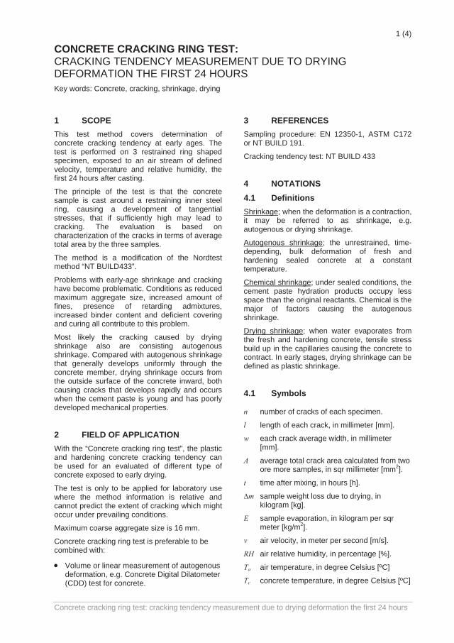
1 (4)
CONCRETE CRACKING RING TEST: CRACKING TENDENCY MEASUREMENT DUE TO DRYING DEFORMATION THE FIRST 24 HOURS Key words: Concrete, cracking, shrinkage, drying
1 SCOPE This test method covers determination of concrete cracking tendency at early ages. The test is performed on 3 restrained ring shaped specimen, exposed to an air stream of defined velocity, temperature and relative humidity, the first 24 hours after casting.
The principle of the test is that the concrete sample is cast around a restraining inner steel ring, causing a development of tangential stresses, that if sufficiently high may lead to cracking. The evaluation is based on characterization of the cracks in terms of average total area by the three samples.
The method is a modification of the Nordtest method “NT BUILD433”.
Problems with early-age shrinkage and cracking have become problematic. Conditions as reduced maximum aggregate size, increased amount of fines, presence of retarding admixtures, increased binder content and deficient covering and curing all contribute to this problem.
Most likely the cracking caused by drying shrinkage also are consisting autogenous shrinkage. Compared with autogenous shrinkage that generally develops uniformly through the concrete member, drying shrinkage occurs from the outside surface of the concrete inward, both causing cracks that develops rapidly and occurs when the cement paste is young and has poorly developed mechanical properties.
2 FIELD OF APPLICATION With the “Concrete cracking ring test”, the plastic and hardening concrete cracking tendency can be used for an evaluated of different type of concrete exposed to early drying.
The test is only to be applied for laboratory use where the method information is relative and cannot predict the extent of cracking which might occur under prevailing conditions.
Maximum coarse aggregate size is 16 mm.
Concrete cracking ring test is preferable to be combined with:
• Volume or linear measurement of autogenous deformation, e.g. Concrete Digital Dilatometer (CDD) test for concrete.
3 REFERENCES
Sampling procedure: EN 12350-1, ASTM C172 or NT BUILD 191.
Cracking tendency test: NT BUILD 433
4 NOTATIONS 4.1 Definitions Shrinkage; when the deformation is a contraction, it may be referred to as shrinkage, e.g. autogenous or drying shrinkage.
Autogenous shrinkage; the unrestrained, time-depending, bulk deformation of fresh and hardening sealed concrete at a constant temperature.
Chemical shrinkage; under sealed conditions, the cement paste hydration products occupy less space than the original reactants. Chemical is the major of factors causing the autogenous shrinkage.
Drying shrinkage; when water evaporates from the fresh and hardening concrete, tensile stress build up in the capillaries causing the concrete to contract. In early stages, drying shrinkage can be defined as plastic shrinkage.
4.1 Symbols
n number of cracks of each specimen.
l length of each crack, in millimeter [mm].
w each crack average width, in millimeter [mm].
A average total crack area calculated from twoore more samples, in sqr millimeter [mm2].
t time after mixing, in hours [h].
∆m sample weight loss due to drying, in kilogram [kg].
E sample evaporation, in kilogram per sqr meter [kg/m2].
v air velocity, in meter per second [m/s].
RH air relative humidity, in percentage [%].
Ta air temperature, in degree Celsius [ºC]
Tc concrete temperature, in degree Celsius [ºC]
Concrete cracking ring test: cracking tendency measurement due to drying deformation the first 24 hours
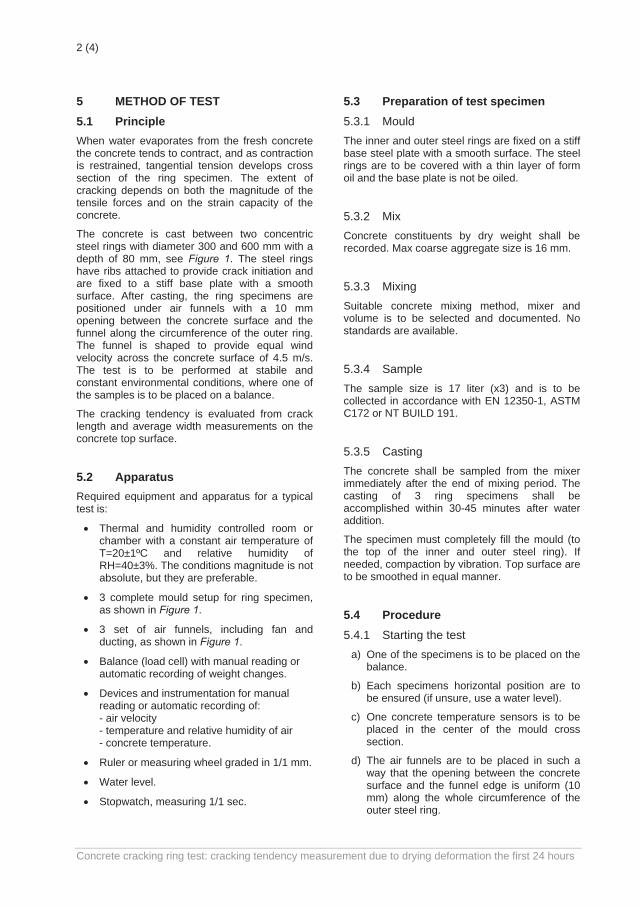
2 (4)
5 METHOD OF TEST 5.1 Principle When water evaporates from the fresh concrete the concrete tends to contract, and as contraction is restrained, tangential tension develops cross section of the ring specimen. The extent of cracking depends on both the magnitude of the tensile forces and on the strain capacity of the concrete.
The concrete is cast between two concentric steel rings with diameter 300 and 600 mm with a depth of 80 mm, see Figure 1. The steel rings have ribs attached to provide crack initiation and are fixed to a stiff base plate with a smooth surface. After casting, the ring specimens are positioned under air funnels with a 10 mm opening between the concrete surface and the funnel along the circumference of the outer ring. The funnel is shaped to provide equal wind velocity across the concrete surface of 4.5 m/s. The test is to be performed at stabile and constant environmental conditions, where one of the samples is to be placed on a balance.
The cracking tendency is evaluated from crack length and average width measurements on the concrete top surface.
5.2 Apparatus Required equipment and apparatus for a typical test is:
• Thermal and humidity controlled room or chamber with a constant air temperature of T=20±1ºC and relative humidity of RH=40±3%. The conditions magnitude is not absolute, but they are preferable.
• 3 complete mould setup for ring specimen, as shown in Figure 1.
• 3 set of air funnels, including fan and ducting, as shown in Figure 1.
• Balance (load cell) with manual reading or automatic recording of weight changes.
• Devices and instrumentation for manual reading or automatic recording of: - air velocity - temperature and relative humidity of air - concrete temperature.
• Ruler or measuring wheel graded in 1/1 mm.
• Water level.
• Stopwatch, measuring 1/1 sec.
5.3 Preparation of test specimen 5.3.1 Mould The inner and outer steel rings are fixed on a stiff base steel plate with a smooth surface. The steel rings are to be covered with a thin layer of form oil and the base plate is not be oiled.
5.3.2 Mix Concrete constituents by dry weight shall be recorded. Max coarse aggregate size is 16 mm.
5.3.3 Mixing Suitable concrete mixing method, mixer and volume is to be selected and documented. No standards are available.
5.3.4 Sample The sample size is 17 liter (x3) and is to be collected in accordance with EN 12350-1, ASTM C172 or NT BUILD 191.
5.3.5 Casting The concrete shall be sampled from the mixer immediately after the end of mixing period. The casting of 3 ring specimens shall be accomplished within 30-45 minutes after water addition.
The specimen must completely fill the mould (to the top of the inner and outer steel ring). If needed, compaction by vibration. Top surface are to be smoothed in equal manner.
5.4 Procedure 5.4.1 Starting the test
a) One of the specimens is to be placed on the balance.
b) Each specimens horizontal position are to be ensured (if unsure, use a water level).
c) One concrete temperature sensors is to be placed in the center of the mould cross section.
d) The air funnels are to be placed in such a way that the opening between the concrete surface and the funnel edge is uniform (10 mm) along the whole circumference of the outer steel ring.
Concrete cracking ring test: cracking tendency measurement due to drying deformation the first 24 hours
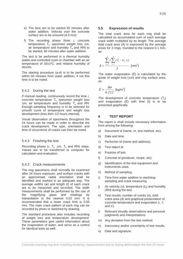
3 (4)
e) The fans are to be started 55 minutes after water addition. Velocity over the concrete surface are to be ensured (4.5 m/s)
f) The recording phase (time t, concrete temperature Tc, specimen weight loss ∆m, air temperature and humidity Ta and RH) to be started, 60 minutes after water addition.
The test is be performed in a thermal humidity stable and controlled room or chamber with an air temperature of 20±1ºC. and relative humidity of 40±3%
The starting procedure (a-d) is to be performed within 60 minutes from water addition, if not this time is to be noted.
5.4.2 During the test If manual reading, continuously record the time t, concrete temperature Tc, specimen weight loss ∆m, air temperature and humidity Ta and RH. Enough sampling frequency is to be selected for smooth curve of temperature and weight loss development (less then 1/2 hours interval).
Visual observation of specimens throughout the 24 hours can be made in order to describe the crack development. The type, orientation and time of occurrence of cracks can then be noted.
5.4.3 Finishing the test Recording phase (t, Tc, ∆m, Ta and RH) stops. Values are to be transferred to computer for calculation and evaluation.
5.4.3 Crack measurements The ring specimens shall normally be examined after 24 hours exposure, and surface cracks with an approximate radial orientation shall be identified and marked in an adequate way. The average widths (w) and length (l) of each crack are to be measured and recorded. The width measurements shall be performed by the use of the magnifying glass and readings by interpolation to the nearest 0.02 mm. It is recommended that a lower crack limit is 0.05 mm. The main crack pattern of each ring can be recorded by photo or sketched by drawing.
The standard procedure also includes recording of weight loss and temperature development. These parameters give useful information about the evaporation of water, and serve as a control for identical tests as well.
5.5 Expression of results The total crack area for each ring shall be calculated as accumulated sum of each average crack width multiplied by its length. The average total crack area (A) is expressed by the average areas for 3 rings, rounded to the nearest 0.1 mm, as:
3
))wl((A
3
1j
n
1iii∑ ∑
= =
⋅= [mm2]
The water evaporation (E) is calculated by the quote of weight loss (∆m) and ring surface area, as:
212.0mE ∆
= [kg/m2]
The development of concrete temperature (Tc) and evaporation (E) with time (t) is to be presented graphically. 6 TEST REPORT The report is shall include necessary information from among the following:
a) Document id (name, nr, test method, etc).
b) Date and time.
c) Performer id (name and address).
d) Test object id.
e) Purpose of test.
f) Concrete id (producer, recipe, etc).
g) Identification of the test equipment and instruments used.
h) Method of sampling.
i) Time from water addition to start/stop sampling and crack measuring.
j) Air velocity (v), temperature (ta) and humidity (RH) during the test.
k) Test results: number of cracks (n), total crack area (A) and graphical presentation of concrete temperature and evaporation (t, Tc and E).
l) Relevant visually observations and personal judgments and interpretations.
m) Any deviation from the test method.
n) Inaccuracy and/or uncertainty of test results.
o) Date and signature.
Concrete cracking ring test: cracking tendency measurement due to drying deformation the first 24 hours
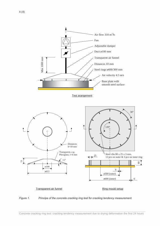
4 (4)
Duct ø100 mm
Min
100
0 m
m
Adjustable damper
Fan
Base plate with smooth steel surface
Transparent air funnel
Distances 10 mm
Steel rings ø600/300 mm
Air flow 310 m3/h
Air velocity 4.5 m/s
Test arangement
51
Transparent, e.g. Plexiglass, t=4 mm
ø100
ø612
11°
Distances h=10 mm
80
ø600 (inner)
120°
30°
ø300 (outer)
6
6
25 Steel ribs 80 x 25 x 3 mm, 12 pcs on outer & 3 pcs on inner ring
Transparent air funnel Ring mould setup
Figure 1. Principe of the concrete cracking ring test for cracking tendency measurement.
Concrete cracking ring test: cracking tendency measurement due to drying deformation the first 24 hours
APPENDED PAPERS

PAPER I: Plastic Shrinkage Cracking in Concrete: State of the Art Sayahi, F., Emborg, M. and Hedlund, H. (2014), published in Nordic Concrete Research, Vol. 51, No. 3, December 2014, pp. 95 – 110.

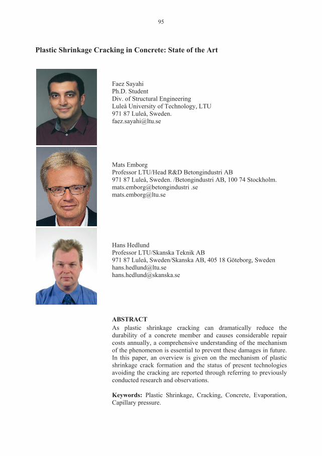
95
Plastic Shrinkage Cracking in Concrete: State of the Art
Faez Sayahi Ph.D. Student Div. of Structural Engineering Luleå University of Technology, LTU 971 87 Luleå, Sweden. [email protected] Mats Emborg Professor LTU/Head R&D Betongindustri AB 971 87 Luleå, Sweden. /Betongindustri AB, 100 74 Stockholm. mats.emborg@betongindustri .se [email protected] Hans Hedlund Professor LTU/Skanska Teknik AB 971 87 Luleå, Sweden/Skanska AB, 405 18 Göteborg, Sweden [email protected] [email protected] ABSTRACT As plastic shrinkage cracking can dramatically reduce the durability of a concrete member and causes considerable repair costs annually, a comprehensive understanding of the mechanism of the phenomenon is essential to prevent these damages in future. In this paper, an overview is given on the mechanism of plastic shrinkage crack formation and the status of present technologies avoiding the cracking are reported through referring to previously conducted research and observations. Keywords: Plastic Shrinkage, Cracking, Concrete, Evaporation, Capillary pressure.
96
1. INTRODUCTION Crack-free concrete structures are needed in order to ensure high level of durability and functionality, since cracks accelerate the ingress of harmful materials that might cause damage in future, e.g. corrosion of the reinforcement [1]. Plastic shrinkage cracking of concrete is often the first type of cracks occurring shortly (within the first few hours) after placing the concrete, even before initial setting [1-4]. As known also settlement cracks can occur very early. According to ACI 305R [5]: “Plastic shrinkage cracking is frequently associated with hot weather concreting in arid climates. It occurs in exposed concrete, primarily in flat work but also in beams and footings and may develop in other climates whenever the evaporation rate is greater than the rate at which the water rises to the surface of recently placed concrete by bleeding”. It is thus understood that this type of cracking, mainly occurring on horizontal concrete elements with large surface to volume ratio (such as slabs, pavements, beams, etc.), can dramatically affect the aesthetics, durability and serviceability of the structure [6, 7]. The main reason behind plastic shrinkage cracking is considered to be rapid and excessive surface water evaporation of the concrete element in the plastic stage (freshly cast concrete) which in turn leads to the so-called plastic or capillary shrinkage [2-5, 8-17]. Consequently, many factors affect the likelihood of plastic shrinkage crack formation such as water-cement ratio, admixture, member size, fines content, concrete surface temperature and ambient conditions (i.e. relative humidity, air temperature and wind velocity). All these factors influence the water evaporation rate of the concrete which is considered, among others, as an indication of the possible beginning of the plastic shrinkage cracking [18]. As long as the evaporation rate is less than the bleeding rate, a thin water film covers the surface of the concrete. Soon after the disappearance of this thin water layer, capillary pressure inside the concrete increases, which results in the so called plastic shrinkage. It should be mentioned here that the bleeding can be very small or not existing at all for concretes of low water/cement ratio, e. g. those designed for fast drying through self-desiccation. If the concrete member is restrained in any way (e.g. due to reinforcement, change of sectional depth, difference in shrinkage in different parts of the concrete, friction of the mould, etc.) , the developed shrinkage can cause tensile strain accumulation, starting from the concrete surface. When the tensile strain exceeds the tensile strain capacity of the concrete, which at early ages is very low, cracks start to form [19]. In many cases, plastic shrinkage cracks are so thin (sometimes invisible to an unaided eye) which can be overlooked or covered by the surface finishing [2]. However, later on phenomena such as external loading, thermal strain, or drying shrinkage can widen the crack which as mentioned earlier negatively influences the serviceability of the concrete structure. Plastic shrinkage cracking, in general, is a complex combination of interdependent variables which can facilitate or prevent the phenomenon under different circumstances. Thus, studying plastic shrinkage cracking requires a high level of persistence and intense theoretical and experimental investigation. In this paper, the phenomenon of plastic shrinkage cracking in concrete is investigated and an attempt is made to reach a comprehensive perspective of the formation process and mechanism. In addition several variables such as water/cement ratio, thickness of the concrete section, fines content, additives, and fibres are briefly described. This research is based on the achievements reported by several researchers around the world and aims to present a state of the art in order to
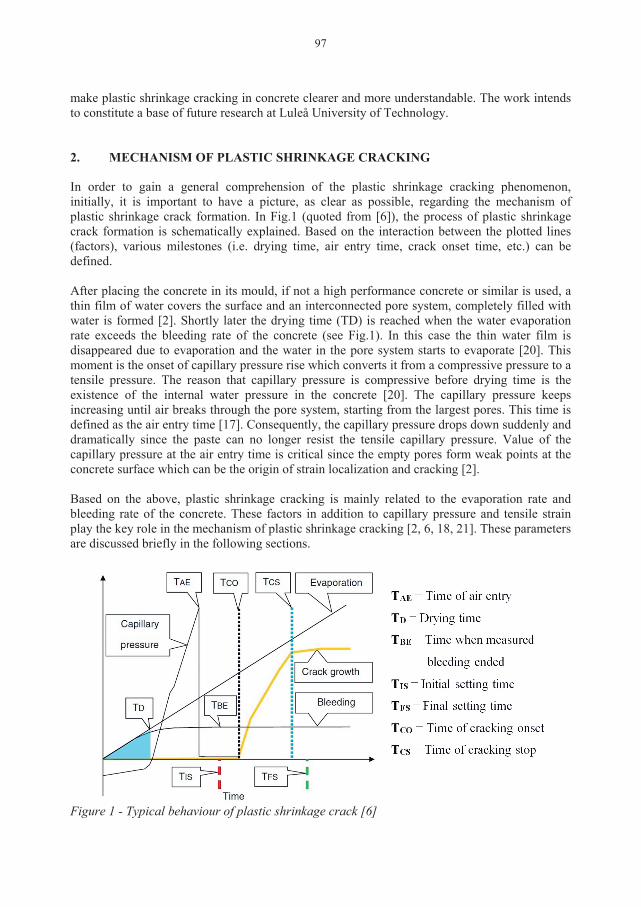
97
make plastic shrinkage cracking in concrete clearer and more understandable. The work intends to constitute a base of future research at Luleå University of Technology. 2. MECHANISM OF PLASTIC SHRINKAGE CRACKING In order to gain a general comprehension of the plastic shrinkage cracking phenomenon, initially, it is important to have a picture, as clear as possible, regarding the mechanism of plastic shrinkage crack formation. In Fig.1 (quoted from [6]), the process of plastic shrinkage crack formation is schematically explained. Based on the interaction between the plotted lines (factors), various milestones (i.e. drying time, air entry time, crack onset time, etc.) can be defined. After placing the concrete in its mould, if not a high performance concrete or similar is used, a thin film of water covers the surface and an interconnected pore system, completely filled with water is formed [2]. Shortly later the drying time (TD) is reached when the water evaporation rate exceeds the bleeding rate of the concrete (see Fig.1). In this case the thin water film is disappeared due to evaporation and the water in the pore system starts to evaporate [20]. This moment is the onset of capillary pressure rise which converts it from a compressive pressure to a tensile pressure. The reason that capillary pressure is compressive before drying time is the existence of the internal water pressure in the concrete [20]. The capillary pressure keeps increasing until air breaks through the pore system, starting from the largest pores. This time is defined as the air entry time [17]. Consequently, the capillary pressure drops down suddenly and dramatically since the paste can no longer resist the tensile capillary pressure. Value of the capillary pressure at the air entry time is critical since the empty pores form weak points at the concrete surface which can be the origin of strain localization and cracking [2]. Based on the above, plastic shrinkage cracking is mainly related to the evaporation rate and bleeding rate of the concrete. These factors in addition to capillary pressure and tensile strain play the key role in the mechanism of plastic shrinkage cracking [2, 6, 18, 21]. These parameters are discussed briefly in the following sections.
Figure 1 - Typical behaviour of plastic shrinkage crack [6]
98
3. EVAPORATION The evaporation is considered as an indicator for the probability of plastic shrinkage cracking onset in freshly placed concrete. For instance, according to ACI, precautions must be taken when the water evaporation rate is equal to or more than 1.0 kg/m2/h [5]. Nevertheless, some experimental results show that this value may be too high for some modern concrete compositions, i.e. plastic shrinkage cracking may occur at evaporation rate of 0.2 kg/m2/h under hot weather conditions [12]. Water evaporation in concrete occurs due to a) heat energy absorption into the water, e.g. air temperature, concrete temperature, solar radiation; b) low humidity, i.e. the ambient pressure is less than that in the water [18]. Accumulation of escaping water molecules above the water surface increases the humidity and consequently decreases the evaporation, especially when the concrete perimeter is closed. Thus, wind can accelerate the process as it removes the escaping water molecules. As can be comprehended from the above, the environmental factors that can highly influence the water evaporation rate are air temperature, concrete (water surface) temperature, wind and humidity. These factors are used in the ACI nomograph for estimating rate of surface water evaporation in concrete (see Fig.2). The outcome of this nomograph is a value for the evaporation rate of the concrete, in which provides an indication of the possible onset of plastic shrinkage cracking [18]. This nomograph was first developed by Bloem in 1960 [22] who in turn used the numerical values presented in a table by Lerch in 1957 [3]. The values in the table were derived using a formula presented by Menzel in 1954, expressed as Eq.1 (only available in imperial unit system)[23]:
W = 0.44(e0 – ea)(0.253 + 0.096 V) (1) where: W = weight (lb) of water evaporated per square foot of surface per hour (lb/ft2/h), e0 = pressure of saturated vapour at the temperature of the evaporating surface, (psi) ea = vapour pressure of the ambient air, (psi) V = Average horizontal air and wind speed measured at about 20 inches (500 mm) above the concrete surface, (mph). In 1998, based on Menzel’s formula, Uno [18] proposed a single operation equation to predict the water evaporation rate. The new formula does not use vapour pressure as input since a temperature-vapour pressure relationship has already been incorporated in the formula. The correlation coefficient of this relationship is 0.99 for the temperature range 15 to 35 ̊ C [18]. The formula is expressed as:
E = 5([Tc + 18]2.5 – r . [Ta + 18]2.5)(V + 4) ×10-6 (2) where E = water evaporation rate, (kg/m2/h) Tc = Concrete (water surface) temperature, (˚C) Ta = air temperature, (˚C) R = relative humidity, (%) V = wind velocity, (km/h).
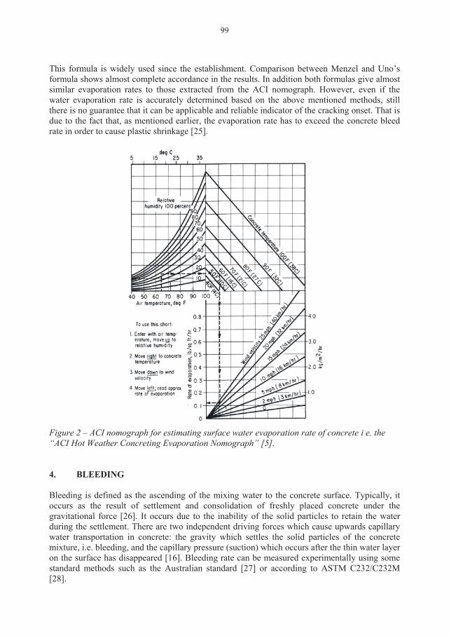
99
This formula is widely used since the establishment. Comparison between Menzel and Uno’s formula shows almost complete accordance in the results. In addition both formulas give almost similar evaporation rates to those extracted from the ACI nomograph. However, even if the water evaporation rate is accurately determined based on the above mentioned methods, still there is no guarantee that it can be applicable and reliable indicator of the cracking onset. That is due to the fact that, as mentioned earlier, the evaporation rate has to exceed the concrete bleed rate in order to cause plastic shrinkage [25].
Figure 2 – ACI nomograph for estimating surface water evaporation rate of concrete i e. the “ACI Hot Weather Concreting Evaporation Nomograph” [5]. 4. BLEEDING Bleeding is defined as the ascending of the mixing water to the concrete surface. Typically, it occurs as the result of settlement and consolidation of freshly placed concrete under the gravitational force [26]. It occurs due to the inability of the solid particles to retain the water during the settlement. There are two independent driving forces which cause upwards capillary water transportation in concrete: the gravity which settles the solid particles of the concrete mixture, i.e. bleeding, and the capillary pressure (suction) which occurs after the thin water layer on the surface has disappeared [16]. Bleeding rate can be measured experimentally using some standard methods such as the Australian standard [27] or according to ASTM C232/C232M [28].
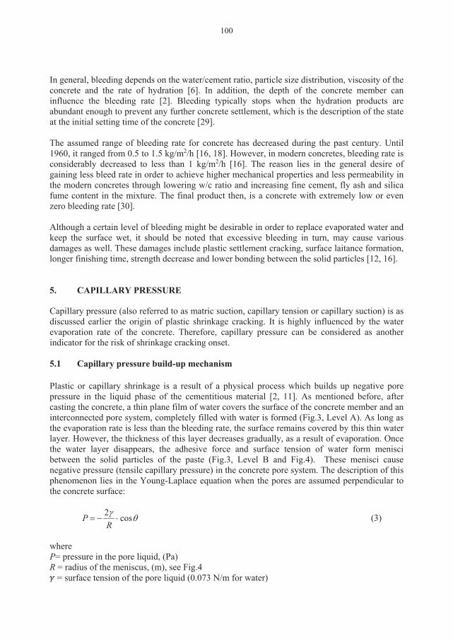
100
In general, bleeding depends on the water/cement ratio, particle size distribution, viscosity of the concrete and the rate of hydration [6]. In addition, the depth of the concrete member can influence the bleeding rate [2]. Bleeding typically stops when the hydration products are abundant enough to prevent any further concrete settlement, which is the description of the state at the initial setting time of the concrete [29]. The assumed range of bleeding rate for concrete has decreased during the past century. Until 1960, it ranged from 0.5 to 1.5 kg/m2/h [16, 18]. However, in modern concretes, bleeding rate is considerably decreased to less than 1 kg/m2/h [16]. The reason lies in the general desire of gaining less bleed rate in order to achieve higher mechanical properties and less permeability in the modern concretes through lowering w/c ratio and increasing fine cement, fly ash and silica fume content in the mixture. The final product then, is a concrete with extremely low or even zero bleeding rate [30]. Although a certain level of bleeding might be desirable in order to replace evaporated water and keep the surface wet, it should be noted that excessive bleeding in turn, may cause various damages as well. These damages include plastic settlement cracking, surface laitance formation, longer finishing time, strength decrease and lower bonding between the solid particles [12, 16]. 5. CAPILLARY PRESSURE Capillary pressure (also referred to as matric suction, capillary tension or capillary suction) is as discussed earlier the origin of plastic shrinkage cracking. It is highly influenced by the water evaporation rate of the concrete. Therefore, capillary pressure can be considered as another indicator for the risk of shrinkage cracking onset. 5.1 Capillary pressure build-up mechanism Plastic or capillary shrinkage is a result of a physical process which builds up negative pore pressure in the liquid phase of the cementitious material [2, 11]. As mentioned before, after casting the concrete, a thin plane film of water covers the surface of the concrete member and an interconnected pore system, completely filled with water is formed (Fig.3, Level A). As long as the evaporation rate is less than the bleeding rate, the surface remains covered by this thin water layer. However, the thickness of this layer decreases gradually, as a result of evaporation. Once the water layer disappears, the adhesive force and surface tension of water form menisci between the solid particles of the paste (Fig.3, Level B and Fig.4). These menisci cause negative pressure (tensile capillary pressure) in the concrete pore system. The description of this phenomenon lies in the Young-Laplace equation when the pores are assumed perpendicular to the concrete surface:
θγ cos2⋅−=
RP (3)
where P= pressure in the pore liquid, (Pa) R = radius of the meniscus, (m), see Fig.4
= surface tension of the pore liquid (0.073 N/m for water)
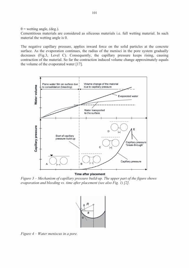
101
θ = wetting angle, (deg.). Cementitious materials are considered as siliceous materials i.e. full wetting material. In such material the wetting angle is 0. The negative capillary pressure, applies inward force on the solid particles at the concrete surface. As the evaporation continues, the radius of the menisci in the pore system gradually decreases (Fig.3, Level C). Consequently, the capillary pressure keeps rising, causing contraction of the material. So far the contraction induced volume change approximately equals the volume of the evaporated water [17].
Figure 3 – Mechanism of capillary pressure build-up. The upper part of the figure shows evaporation and bleeding vs. time after placement (see also Fig. 1) [2].
Figure 4 – Water meniscus in a pore.
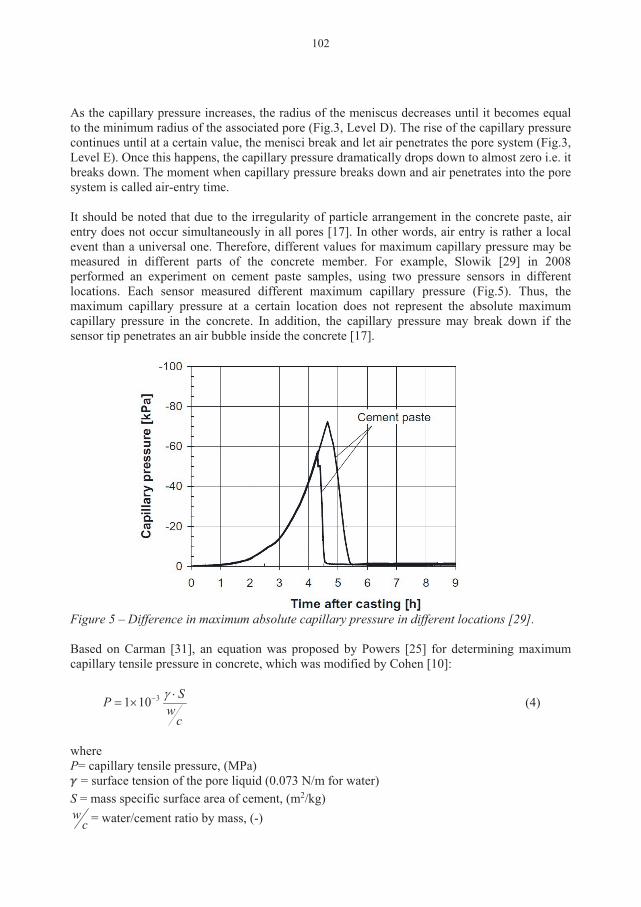
102
As the capillary pressure increases, the radius of the meniscus decreases until it becomes equal to the minimum radius of the associated pore (Fig.3, Level D). The rise of the capillary pressure continues until at a certain value, the menisci break and let air penetrates the pore system (Fig.3, Level E). Once this happens, the capillary pressure dramatically drops down to almost zero i.e. it breaks down. The moment when capillary pressure breaks down and air penetrates into the pore system is called air-entry time. It should be noted that due to the irregularity of particle arrangement in the concrete paste, air entry does not occur simultaneously in all pores [17]. In other words, air entry is rather a local event than a universal one. Therefore, different values for maximum capillary pressure may be measured in different parts of the concrete member. For example, Slowik [29] in 2008 performed an experiment on cement paste samples, using two pressure sensors in different locations. Each sensor measured different maximum capillary pressure (Fig.5). Thus, the maximum capillary pressure at a certain location does not represent the absolute maximum capillary pressure in the concrete. In addition, the capillary pressure may break down if the sensor tip penetrates an air bubble inside the concrete [17].
Figure 5 – Difference in maximum absolute capillary pressure in different locations [29]. Based on Carman [31], an equation was proposed by Powers [25] for determining maximum capillary tensile pressure in concrete, which was modified by Cohen [10]:
cw
SP ⋅×= − γ3101 (4)
where P= capillary tensile pressure, (MPa)
= surface tension of the pore liquid (0.073 N/m for water) S = mass specific surface area of cement, (m2/kg)
cw = water/cement ratio by mass, (-)
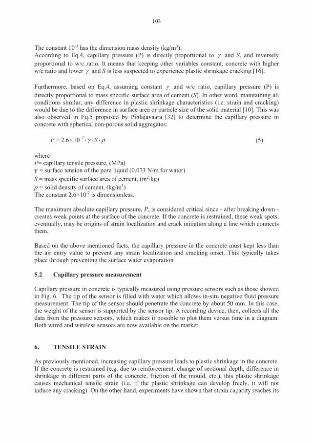
103
The constant 10-3 has the dimension mass density (kg/m3). According to Eq.4, capillary pressure (P) is directly proportional to γ and S, and inversely proportional to w/c ratio. It means that keeping other variables constant, concrete with higher w/c ratio and lower γ and S is less suspected to experience plastic shrinkage cracking [16]. Furthermore, based on Eq.4, assuming constant γ and w/c ratio, capillary pressure (P) is directly proportional to mass specific surface area of cement (S). In other word, maintaining all conditions similar, any difference in plastic shrinkage characteristics (i.e. strain and cracking) would be due to the difference in surface area or particle size of the solid material [10]. This was also observed in Eq.5 proposed by Pihlajavaara [32] to determine the capillary pressure in concrete with spherical non-porous solid aggregates:
ργ ⋅⋅⋅×= − SP 7106.2 (5) where P= capillary tensile pressure, (MPa)
= surface tension of the pore liquid (0.073 N/m for water) S = mass specific surface area of cement, (m2/kg) ρ = solid density of cement, (kg/m3) The constant 2.6×10⁻⁷ is dimensionless. The maximum absolute capillary pressure, P, is considered critical since - after breaking down - creates weak points at the surface of the concrete. If the concrete is restrained, these weak spots, eventually, may be origins of strain localization and crack initiation along a line which connects them. Based on the above mentioned facts, the capillary pressure in the concrete must kept less than the air entry value to prevent any strain localization and cracking onset. This typically takes place through preventing the surface water evaporation 5.2 Capillary pressure measurement Capillary pressure in concrete is typically measured using pressure sensors such as those showed in Fig. 6. The tip of the sensor is filled with water which allows in-situ negative fluid pressure measurement. The tip of the sensor should penetrate the concrete by about 50 mm. In this case, the weight of the sensor is supported by the sensor tip. A recording device, then, collects all the data from the pressure sensors, which makes it possible to plot them versus time in a diagram. Both wired and wireless sensors are now available on the market.
6. TENSILE STRAIN As previously mentioned, increasing capillary pressure leads to plastic shrinkage in the concrete. If the concrete is restrained (e.g. due to reinforcement, change of sectional depth, difference in shrinkage in different parts of the concrete, friction of the mould, etc.), this plastic shrinkage causes mechanical tensile strain (i.e. if the plastic shrinkage can develop freely, it will not induce any cracking). On the other hand, experiments have shown that strain capacity reaches its
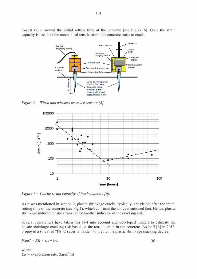
104
lowest value around the initial setting time of the concrete (see Fig.7) [6]. Once the strain capacity is less than the mechanical tensile strain, the concrete starts to crack.
Figure 6 – Wired and wireless pressure sensors [2]
Figure 7 – Tensile strain capacity of fresh concrete [6]. As it was mentioned in section 2, plastic shrinkage cracks, typically, are visible after the initial setting time of the concrete (see Fig.1), which confirms the above mentioned fact. Hence, plastic shrinkage induced tensile strain can be another indicator of the cracking risk. Several researchers have taken this fact into account and developed models to estimate the plastic shrinkage cracking risk based on the tensile strain in the concrete. Boshoff [6] in 2013, proposed a so-called “PShC severity model” to predict the plastic shrinkage cracking degree: PShC = ER × tset ̶ Wbl (6) where ER = evaporation rate, (kg/m2/h)
105
tset = the time between casting and the initial setting time, (hr) Wbl = the total bleed water, (kg/m2). According to this model, the severity of plastic shrinkage cracking is dependent on the plastic shrinkage strain which is directly related to the rate of water evaporation, hardening time of the concrete (initial setting time) and bleeding characteristics [6]. In other word, it relates the severity of plastic shrinkage cracking to the amount of the evaporated water (total amount of evaporated water, minus the bleed water) from within the concrete, between the casting and initial setting time [6]. 7. MAIN FACTORS AFFECTING PLASTIC SHRINKAGE CRACKING So far, the main parameters in the mechanism of plastic shrinkage formation, (i.e. evaporation rate, bleeding rate, capillary pressure and tensile strain) and the relation between them have been briefly described. Fig. 8 is an attempt so summarize the parameters mentioned and the way they are linked together. Nevertheless, there are many factors which can affect plastic shrinkage cracking. A deep comprehension of the way these factors influence the whole cracking process can lead to invention of new crack prevention methods. Some of these factors are briefly described in the following , including water/cement ratio, depth of the concrete section, additives, fines content, fibres and curing measures. 7.1 Water/cement Ratio Water/cement ratio plays a key role in plastic shrinkage cracks formation. Higher w/c ratio means more bleeding water and vice versa. Thus, in case of high w/c ratio, it takes longer time for the surface water layer to disappear due to evaporation and consequently delays the capillary pressure build-up in the pore system. It is known that a lower w/c ratio causes less bleeding water and thus increases the risk of cracking [33]. On the other hand w/c ratio has an inverse relation with the concrete strength as higher w/c ratio causes lower concrete strength and vice versa. Research has shown that high-strength concrete mixtures (containing more cement) have low bleeding rate and subsequently higher risk of plastic shrinkage cracking [34]. Thus, optimizing the w/c ratio can be a method to avoid plastic shrinkage crack formation. If high-strength concrete is not necessary, it may be a good idea to use higher w/c ratio. However, it should be noted that very high w/c ratio can dramatically reduce the durability and serviceability of the concrete member. 7.2 Depth of the concrete section A deeper concrete member typically experiences more settlement, since it contains more settling solid particles. Correspondingly, for higher w/c ratios, the bleeding capacity of the member is higher resulting in more bleed water accumulation on the surface. This means that the surface water layer evaporation takes longer time in comparison, causing delay in capillary pressure build-up. Consequently, it can be concluded that a deeper concrete section is less prone to plastic shrinkage cracking [8, 35]. However, due to the high degree of settlement, the concrete may be vulnerable to settlement cracking typically formed above the reinforcement bars, which may facilitate the ingress of chlorides and other harmful materials.
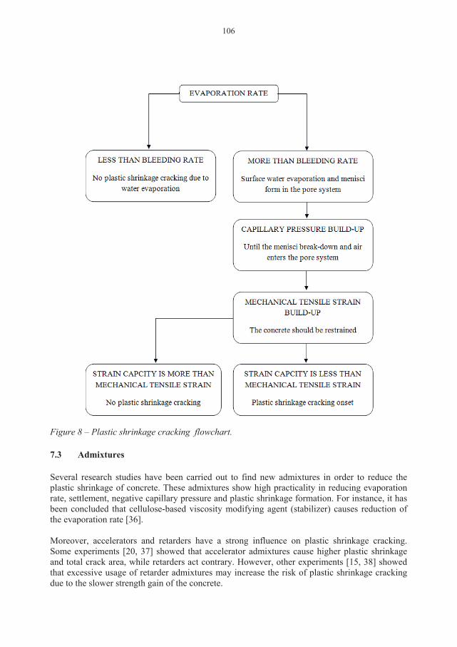
106
Figure 8 – Plastic shrinkage cracking flowchart. 7.3 Admixtures Several research studies have been carried out to find new admixtures in order to reduce the plastic shrinkage of concrete. These admixtures show high practicality in reducing evaporation rate, settlement, negative capillary pressure and plastic shrinkage formation. For instance, it has been concluded that cellulose-based viscosity modifying agent (stabilizer) causes reduction of the evaporation rate [36]. Moreover, accelerators and retarders have a strong influence on plastic shrinkage cracking. Some experiments [20, 37] showed that accelerator admixtures cause higher plastic shrinkage and total crack area, while retarders act contrary. However, other experiments [15, 38] showed that excessive usage of retarder admixtures may increase the risk of plastic shrinkage cracking due to the slower strength gain of the concrete.
107
On the other hand, superplasticizers reduce the need for water in the concrete mixtures (less bleed water at the surface). This reduction of surface water may however not increase the risk of cracking, as the superplasticizer modifies the surface tension and prevent or delays the onset of plastic shrinkage crack formation [39]. 7.4 Fibres Fibres (steel and/or polypropylene) have often been recently used in concrete mixtures aiming at lowering the risk of plastic shrinkage cracking, through stitching the concrete surface particles together. For instance experimental results presented by Sivakumar and Santhanam [7] show that a combination of steel and polypropylene fibres (hybrid fibres), can reduce the width of the plastic shrinkage crack up to 55% in comparison to concrete mixture without fibres usage. However, the only problem is that although the crack width was lower, parallel cracks were formed in the main crack’s surroundings. This phenomenon can be due to the transfer of the shrinkage stresses, through the fibres, to the surrounding areas. The number of these parallel cracks could be reduced in case of steel fibre usage. The reason lies in more fibre availability in case of hybrid usage compared to the steel fibre system (due to the lower density of polypropylene fibre in comparison to steel fibres), which facilitates the shrinkage stress transfer. Nevertheless, hybrid fibres show a great enhancement in relation to reducing plastic shrinkage cracks [7]. 7.5 Fines content Fines (such as fly ash, silica fume, slag, etc.) induce greater surface area to adsorb water. Consequently, the water that is supposed to be transported to the concrete surface will be adsorbed on the fine particles, resulting in lower bleeding rate. Cohen et al. [10] concluded that higher surface area of the particles leads to higher tensile capillary pressure and eventually higher probability of plastic shrinkage crack formation. Moreover, experiments performed by Esping et al. [15] showed that silica fume increases the crack tendency in the concrete. Thus, using high proportion of fine material in the concrete mixture is not favourable in relation to plastic shrinkage cracking. 7.6 Curing measures Plastic shrinkage cracks can be avoided through several curing measures applied on the concrete after casting. Since the main reason behind this phenomenon is water evaporation, curing measures in general aim to eliminate or reduce the evaporation of the surface water. For example covering the concrete with plastic sheet, decreases the evaporation rate and consequently leads to a crack-free concrete [40]. In another case, experiments have shown that evaporation of the surface water can be suppressed through spraying aliphatic alcohols over the fresh concrete surface [41]. Moreover, in some cases curing the concrete takes place through replacing the evaporated surface water (rewetting). For example, fogging the freshly cast concrete surface, on one hand, reduces the evaporation rate through increasing the ambient relative humidity, and on the other hand, replaces some lost surface water due to evaporation [17].
108
In addition to the above, using a wind breaker to prevent or reduce the air flow over the concrete surface can be another way to reduce the evaporation of the surface water [18]. 8. CONCLUSION Plastic shrinkage cracking is a complex interaction of several variables that may change in different circumstances. These variables have direct influence on the evaporation and bleed rate of the concrete which subsequently affect the capillary pressure and tensile strain at the early age. The explanations offered in this paper for the plastic shrinkage cracking mechanism and the role of each variable in the process may facilitate gaining a comprehensive understanding of the phenomenon. Moreover, knowing the influence of each variable can lead to innovation of new crack preventive measures. Despite of the general consensus on the major role of water evaporation in the plastic shrinkage crack formation, not all the cracking incidents are explainable based on that. This illustrates the incompletely understood aspects of the whole process. The inter-connection and complexity of the different variables need to be explored. Thus, in the future, emphasis should be on documenting the various factors through laboratory tests under controlled conditions. ACKNOWLEDGMENT The authors would like to gratefully appreciate the financial support they received from the Development Fund of the Swedish Construction Industry, SBUF. REFERENCES 1. Leemann A, Nygaard P, Lura P. "Impact of admixtures on the plastic shrinkage cracking of
self-compacting concrete". Cement and Concrete Composites. Vol.46, 2014, pp.1-7. 2. Schmidt M, Slowik V. "Instrumentation for optimizing concrete curing". Concrete
International. 2013;35(8). 3. Lerch W. "Plastic shrinkage". ACI journal proceedings; ACI; 1957. 4. Ravina D, Shalon R. "Plastic shrinkage cracking". ACI journal proceedings; ACI; 1968. 5. "ACI D. 305R-hot weather concreting". American Concrete Institute International, 1999. 6. Boshoff WP, Combrinck R. "Modelling the severity of plastic shrinkage cracking in
concrete". Cement and Concrete Research. Vol.48, 2013 JUN, pp.34-39. 7. Sivakumar A, Santhanam M. "Experimental methodology to study plastic shrinkage cracks in
high strength concrete. In: Measuring, Monitoring and Modelling Concrete Properties. Springer, 2006. pp. 291-296.
8. Van Dijk J, Boardman V. "Plastic shrinkage cracking of concrete". RILEM international symposium of concrete and reinforced concrete in hot countries, Technion, Israel institute of technology, Haifa, 1971, pp. 225-239.
9. Kasai Y, Vokoyama K, Matsui I. "Tensile properties of early-age concrete. Proceedings of conference on mechanical behaviour of materials". 1972, pp.288-299.
109
10. Cohen MD, Olek J, Dolch WL. "Mechanism of plastic shrinkage cracking in Portland cement and Portland cement-silica fume paste and mortar". Cement and Concrete Research, Vol.20, No.1, 1990, pp.103-119.
11. Radocea A. "A study on the mechanism of plastic shrinkage of cement-based materials". Chalmers University of Technology,; 1992.
12. Almusallam A, Abdul-Waris M, Maslehuddin M, Al-Gahtani A. "Placing and shrinkage at extreme temperatures". Concrete International, Vol.21, 1999, pp.75-79.
13. Qi C, Weiss J, Olek J. "Characterization of plastic shrinkage cracking in fiber reinforced concrete using image analysis and a modified weibull function". Materials and Structures. Vol.36, No.6, 2003, pp.386-395.
14. Josserand L, Coussy O, de Larrard F. "Bleeding of concrete as an ageing consolidation process". Cement and Concrete Research,Vol.36, No.9, 2006, pp.1603-1608.
15. Esping O, Löfgren I, Marchand J, Bissonnette B, Gagné R, Jolin M, et al. "Investigation of early age deformation in self-compacting concrete". 2nd International Symposium on Advances in Concrete through Science and Engineering, 11-13 September 2006, Quebec City, Canada,
16. Dao V, Dux P, Morris P, O'Moore L. "Plastic shrinkage cracking of concrete". Australian Journal of Structural Engineering. Vol.10, No.3, 2010, pp.207-214.
17. Slowik V, Schmidt M. "Early age cracking and capillary pressure controlled concrete curing". Advance in Cement-Based Material. 2010.
18. Uno PJ. "Plastic shrinkage cracking and evaporation formulas". ACI Mater Journal. Vol.95, 1998, pp.365-375.
19. Ghoddousi P, Javid AAS. "Effect of reinforcement on plastic shrinkage and settlement of self-consolidating concrete as repair material". Materials and Structures, Vol.45, No.1-2, 2012, pp.41-52.
20. Combrinck R, Boshoff WP. "Typical plastic shrinkage cracking behaviour of concrete". Magazine of Concrete Research, Vol.65, No.8, 2013, pp.486-493.
21. Radocea A. "A model of plastic shrinkage". Magazine of Concrete Research,Vol.46, No.167, 1994, pp.125-132.
22. Bloem D. "Plastic cracking of concrete". Engineering Information. 1960. 23. Menzel CA. "Causes and prevention of crack development in plastic concrete". Proceedings
of the Portland Cement Association. 1954, pp.130-136. 24. Goff JA, Gratch S. "Low-pressure properties of water from-160 to 212 F". Transaction of
the American Society Heating and Ventilating Engineers, Vol.51, 1946, pp.125-164. 25. Powers TC. "The properties of fresh concrete". John Wiley and sons, 1969. 26. Kwak H, Ha S, Weiss WJ. "Experimental and numerical quantification of plastic settlement
in fresh cementitious systems". Journal of Material of Civil Engineering, Vol.22, No.10, 2010, pp.951-966.
27. Standards Australia 1999. "Method for the determination of bleeding of concrete". 1999. Report No.: AS1012.6-1999.
28. ASTM C232/C232M. "Standard test method for bleeding of concrete". American Society of Testing and Material, 2013.
29. Slowik V, Schmidt M, Fritzsch R. "Capillary pressure in fresh cement-based materials and identification of the air entry value," Cement and Concrete composites, Vol.30, No.7, 2008, pp.557-565.
30. Khayat KH. "Workability, testing, and performance of self-consolidating concrete". ACI Material Journal, Vol.96, No.3, 1999.
31. Carman P. "Capillary rise and capillary movement of moisture in fine sands," Soil Science, Vol.52, No.1, 1941, pp.1-14.
110
32. Pihlajavaara S. "A review of some of the main results of a research on the ageing phenomena of concrete: Effect of moisture conditions on strength, shrinkage and creep of mature concrete," Cement and Concrete Research,Vol.4, No.5, 1974, pp.761-771.
33. Lund A, Skoog M, Thorstensson R. ”Plastiska krympsprickor i betong”,. Dept. of Structural Mechanics and Engineering, Royal Institute of Technology, Stockholm, Sweden, 1997. (in swedish)
34. Samman TA, Mirza WH, Wafa FF. "Plastic shrinkage cracking of normal and high-strength concrete: A comparative study," ACI Material Journal, Vol.93, No.1, 1996, pp.36-40.
35. Schiessl P, Schmidt R. "Bleeding of concrete," RILEM proceedings of the colloquium, Hanover, 1990, pp.24-32.
36. Lin S, Huang R. "Effect of viscosity modifying agent on plastic shrinkage cracking of cementitious composites," Material and Structure. Vol.43, No.5, 2010, pp.651-664.
37. Kronlöf A, Leivo M, Sipari P. "Experimental study on the basic phenomena of shrinkage and cracking of fresh mortar," Cement and Concrete Research,Vol.25, No.8, 1995, pp.1747-1754.
38. Soroka I. "Concrete in hot environments," CRC Press, 2003, 251 pp. 39. Cabrera J, Cusens A, Brookes-Wang Y. "Effect of superplasticizers on the plastic shrinkage
of concrete," Magazine of Concrete Research, Vol.44, No.160, 1992, pp.149-155. 40. Hedin, C., "Plastiska Krympsprickor – Motåtgärder", Internal technical report 85-3. Central
laboratory of Betongindustri AB, 1985, (in Swedish). 41. Cordon, W. A., Thorpe, J. D., "Control of Rapid Drying of Fresh Concrete by Evaporation
Control", ACI Journal, Proceedings Aug. 1965, pp. 977-984.
PAPER II: Effect of admixtures on the mechanism of plastic shrinkage cracking in self-compacting concrete
Sayahi, F., Emborg, M., Hedlund, H., and Cwirzen, A., Submitted.


Effect of admixtures on the mechanism of plastic shrinkage cracking in self-compacting concrete Faez Sayahia,*, Mats Emborga,b, Hans Hedlunda,c, Andrzej Cwirzena
a Department of Civil, Environmental and Natural Resources Engineering, Luleå University of Technology, 971 87 Luleå, Sweden b Betongindustri AB, 100 74 Stockholm, Sweden. c Skanska Sverige AB, Gothenburg, Sweden *Corresponding author: Faez Sayahia, e-mail: [email protected], telephone number: +46 76 409 1933. ABSTRACT The main reason for plastic shrinkage cracking is believed to be excessive moisture loss, mainly due to evaporation. This research studies the effect of retarder, accelerator, stabilizer, air-entraining agent (AEA) and shrinkage reducing admixture (SRA) on plastic shrinkage cracking in self-compacting concrete (SCC). The main objective is to fill the knowledge gap regarding the effect of admixtures on the volumetric shrinkage of SCC. During the research, a modified ASTM C 1579 mould and a ring test set-up was used to measure the effect of the admixtures on the early age cracking. The results show that AEA and SRA were highly effective in reducing the cracking tendency, while accelerator and retarder increased it. The impact of admixtures on the cracking mechanism is identified, by comparing the respective vertical and horizontal deformations. It was observed that crack-free concretes had moderate settlement and horizontal shrinkage, while the cracked specimens exhibited significant deformation either vertically or horizontally. Keywords: Self-compacting concrete, Cracking, Plastic shrinkage, Admixtures, Settlement, Horizontal deformation. 1. INTRODUCTION Plastic shrinkage cracking in concrete occurs between the time of placement and the final set, when the concrete has not yet gained enough tensile strain capacity [1-3]. Besides the negative aesthetic effect, cracks facilitate the ingress of aggressive materials that might cause damage and durability problems in future, e.g. corrosion of the reinforcement. Horizontal concrete elements with large surface to volume ratio, such as slabs and pavements, are more prone to the phenomenon. Moreover, self-compacting concrete (SCC) or concretes with low water-binder ratio have a greater risk of plastic shrinkage cracking due to their significant early-age deformation [4]. Immediately after casting, settlement of the solid particles will cause bleeding – that is, upward movement of the pore water to the surface. As the concrete is still in its plastic stage, rapid and excessive moisture loss mainly due to evaporation leads to menisci formation in the concrete pore system. Consequently, negative capillary pressure builds up, which in turn causes contraction [5-12]. The progressive consolidation, eventually lead to loss of workability, at which stage, settlement stops and the concrete continues to shrink horizontally. Many parameters may affect the risk of plastic shrinkage cracking, including the water/cement ratio (w/c), admixtures, member size, fine content, temperature of the concrete surface and ambient conditions (such as relative humidity, air temperature and wind velocity) [13]. It seems that the phenomenon is also closely related to the duration of the dormant period [14].
Admixtures in particular can significantly affect the severity of plastic shrinkage of fresh concrete. Studies have revealed that the use of shrinkage-reducing admixture (SRA) leads to less water evaporation, reduction of settlement, lower capillary pressure and lower tendency for plastic shrinkage cracking [14, 15, 16]. Lura et al. [14] studied the development of plastic shrinkage cracks in mortars containing 0, 1, 2 and 5% SRA by mass of water. They concluded that the reduction of the surface tension of the pore fluid due to the addition of SRA results in less evaporation, decreased settlement, reduced capillary tension, and lower crack-inducing stresses. Ruacho et al. [15] investigated the effect of SRA on conventional and high strength concretes. They measured the capillary pressure, settlement, internal temperature and water evaporation and reached the same conclusions as Lura et al. [14]. Saliba et al. [16] observed that SRA did not affect the plastic shrinkage of the mix with w/c of 0.65, whereas the cracking tendency of the concrete with w/c of 0.43 was reduced by 25% [16]. Leeman et al. [17] studied the impact of several admixtures, including modified starch-based stabilizers on plastic shrinkage cracking of SCC. They observed that adding stabilizer to the mixture led to wider cracks, decreased capillary pressure build-up rate, retarded hydration and more bleeding and settlement. Lin and Huang [18], on the other hand, noticed that cellulose-based stabilizers reduce the evaporation rate and the intensity of plastic shrinkage cracking. According to Combrinck and Boshoff [19], accelerators increase the horizontal shrinkage and the cracking, while retarders have the opposite effect. However, other researchers reported that accelerators and retarders respectively decrease and increase the cracking tendency [17, 20, 21]. Furthermore, Esping and Löfgren [4] studied the effect of synthetic surfactant-based air-entraining agent (AEA) on SCC with w/c of 0.67. They observed that by adding AEA to the concrete, its early-age cracking tendency is reduced by half. The same conclusion was made by Kronlöf et al. [22], where the concrete exhibited smaller horizontal shrinkage after the addition of AEA based on polyglycol ether sulphonate. Combrinck et al. [23], studied the influence of a minimum and maximum dosage of a glucose-based retarder, calcium chloride-based accelerator, chloride free air entraining agent, lignosulphonate plasticizer, SRA, poly carboxylate ether (PCE) based superplasticizer, and a sulphonated melamine formaldehyde (SMF) based superplasticizer, on plastic shrinkage of conventional and high-flow concrete. It was observed that the respective admixtures reduced
the crack area, capillary pressure, amount of the evaporated water and the evaporation rate, as well as the settlement-shrinkage behaviour in both types of concrete [23]. They attributed this behaviour to the mixed water surface tension-reducing effect of the tested admixtures and the consequent alteration of bleeding, evaporation and capillary pressure. So far, few papers have been published about the influence of admixtures on plastic shrinkage cracking, out of which only some have focused on SCC. However, despite the fact that almost all of them measured settlement, evaporation, internal heat evolution, capillary pressure and the impact on cracking tendency, the influence of admixtures on the mechanism of plastic shrinkage appears to remain poorly understood. In other words, the role of volumetric deformation in plastic shrinkage cracking of concretes containing admixtures is very seldom studied, in contrast to one-dimensional deformation (settlement). Even though some researchers measured both vertical and horizontal deformation [19, 22, 23], a solid conclusion regarding the role of each deformation in the process of plastic shrinkage cracking is still missing. Thus, this paper identifies the impact of admixtures on the cracking mechanism of SCC in the plastic state, based on the concrete vertical and horizontal deformations.
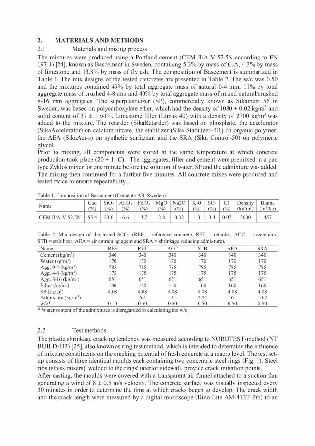
2. MATERIALS AND METHODS 2.1 Materials and mixing process The mixtures were produced using a Portland cement (CEM II/A-V 52.5N according to EN 197-1) [24], known as Bascement in Sweden, containing 5.3% by mass of C3A, 4.3% by mass of limestone and 13.8% by mass of fly ash. The composition of Bascement is summarized in Table 1. The mix designs of the tested concretes are presented in Table 2. The w/c was 0.50 and the mixtures contained 49% by total aggregate mass of natural 0-4 mm, 11% by total aggregate mass of crushed 4-8 mm and 40% by total aggregate mass of mixed natural/crushed 8-16 mm aggregates. The superplasticizer (SP), commercially known as Sikament 56 in Sweden, was based on polycarboxylate ether, which had the density of 1080 ± 0.02 kg/m3 and solid content of 37 ± 1 wt%. Limestone filler (Limus 40) with a density of 2700 kg/m3 was added to the mixture. The retarder (SikaRetarder) was based on phosphate, the accelerator (SikaAccelerator) on calcium nitrate, the stabilizer (Sika Stabilizer–4R) on organic polymer, the AEA (SikaAer-s) on synthetic surfactant and the SRA (Sika Control-50) on polymeric glycol. Prior to mixing, all components were stored at the same temperature at which concrete production took place (20 ± 1 ˚C). The aggregates, filler and cement were premixed in a pan type Zyklos mixer for one minute before the solution of water, SP and the admixture was added. The mixing then continued for a further five minutes. All concrete mixes were produced and tested twice to ensure repeatability. Table 1, Composition of Bascement (Cementa AB, Sweden).
Name Cao (%)
SiO2 (%)
Al2O3 (%)
Fe2O3 (%)
MgO (%)
Na2O (%)
K2O (%)
SO3 (%)
CI-
(%) Density (kg/m3)
Blaine (m2/kg)
CEM II/A-V 52.5N 55.4 23.6 6.6 3.7 2.8 0.32 1.3 3.4 0.07 3000 457
Table 2, Mix design of the tested SCCs (REF = reference concrete, RET = retarder, ACC = accelerator, STB = stabilizer, AEA = air entraining agent and SRA = shrinkage reducing admixture).
Name REF RET ACC STB AEA SRA Cement (kg/m3) 340 340 340 340 340 340 Water (kg/m3) 170 170 170 170 170 170 Agg. 0-4 (kg/m3) 785 785 785 785 785 785 Agg. 4-8 (kg/m3) 175 175 175 175 175 175 Agg. 8-16 (kg/m3) 651 651 651 651 651 651 Filler (kg/m3) 160 160 160 160 160 160 SP (kg/m3) 4.08 4.08 4.08 4.08 4.08 4.08 Admixture (kg/m3) - 6.5 7 3.74 6 10.2 w/c* 0.50 0.50 0.50 0.50 0.50 0.50
* Water content of the admixtures is disregarded in calculating the w/c.
2.2 Test methods The plastic shrinkage cracking tendency was measured according to NORDTEST-method (NT BUILD 433) [25], also known as ring test method, which is intended to determine the influence of mixture constituents on the cracking potential of fresh concrete at a macro level. The test set-up consists of three identical moulds each containing two concentric steel rings (Fig. 1). Steel ribs (stress raisers), welded to the rings' interior sidewall, provide crack initiation points. After casting, the moulds were covered with a transparent air funnel attached to a suction fan, generating a wind of 8 ± 0.5 m/s velocity. The concrete surface was visually inspected every 30 minutes in order to determine the time at which cracks began to develop. The crack width and the crack length were measured by a digital microscope (Dino Lite AM-413T Pro) to an
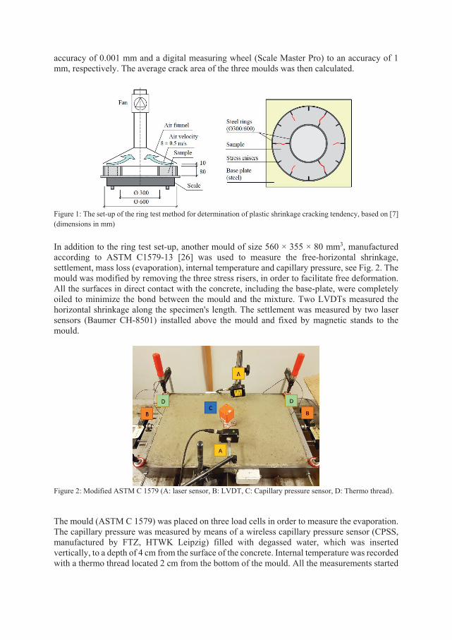
accuracy of 0.001 mm and a digital measuring wheel (Scale Master Pro) to an accuracy of 1 mm, respectively. The average crack area of the three moulds was then calculated.
Figure 1: The set-up of the ring test method for determination of plastic shrinkage cracking tendency, based on [7] (dimensions in mm) In addition to the ring test set-up, another mould of size 560 × 355 × 80 mm3, manufactured according to ASTM C1579-13 [26] was used to measure the free-horizontal shrinkage, settlement, mass loss (evaporation), internal temperature and capillary pressure, see Fig. 2. The mould was modified by removing the three stress risers, in order to facilitate free deformation. All the surfaces in direct contact with the concrete, including the base-plate, were completely oiled to minimize the bond between the mould and the mixture. Two LVDTs measured the horizontal shrinkage along the specimen's length. The settlement was measured by two laser sensors (Baumer CH-8501) installed above the mould and fixed by magnetic stands to the mould.
Figure 2: Modified ASTM C 1579 (A: laser sensor, B: LVDT, C: Capillary pressure sensor, D: Thermo thread).
The mould (ASTM C 1579) was placed on three load cells in order to measure the evaporation. The capillary pressure was measured by means of a wireless capillary pressure sensor (CPSS, manufactured by FTZ, HTWK Leipzig) filled with degassed water, which was inserted vertically, to a depth of 4 cm from the surface of the concrete. Internal temperature was recorded with a thermo thread located 2 cm from the bottom of the mould. All the measurements started
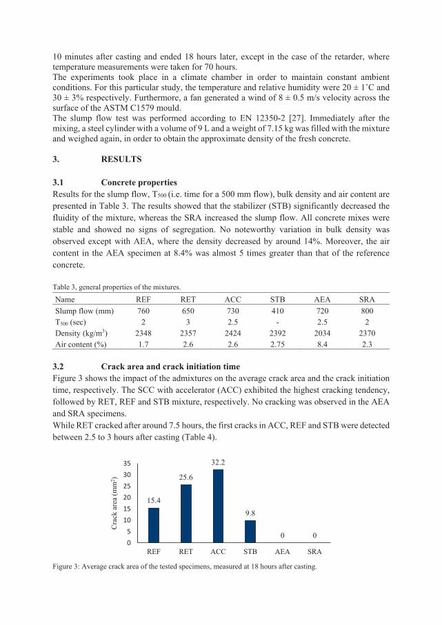
10 minutes after casting and ended 18 hours later, except in the case of the retarder, where temperature measurements were taken for 70 hours. The experiments took place in a climate chamber in order to maintain constant ambient conditions. For this particular study, the temperature and relative humidity were 20 ± 1˚C and 30 ± 3% respectively. Furthermore, a fan generated a wind of 8 ± 0.5 m/s velocity across the surface of the ASTM C1579 mould. The slump flow test was performed according to EN 12350-2 [27]. Immediately after the mixing, a steel cylinder with a volume of 9 L and a weight of 7.15 kg was filled with the mixture and weighed again, in order to obtain the approximate density of the fresh concrete. 3. RESULTS 3.1 Concrete properties Results for the slump flow, T500 (i.e. time for a 500 mm flow), bulk density and air content are presented in Table 3. The results showed that the stabilizer (STB) significantly decreased the fluidity of the mixture, whereas the SRA increased the slump flow. All concrete mixes were stable and showed no signs of segregation. No noteworthy variation in bulk density was observed except with AEA, where the density decreased by around 14%. Moreover, the air content in the AEA specimen at 8.4% was almost 5 times greater than that of the reference concrete. Table 3, general properties of the mixtures.
Name REF RET ACC STB AEA SRA Slump flow (mm) 760 650 730 410 720 800 T500 (sec) 2 3 2.5 - 2.5 2 Density (kg/m3) 2348 2357 2424 2392 2034 2370 Air content (%) 1.7 2.6 2.6 2.75 8.4 2.3
3.2 Crack area and crack initiation time Figure 3 shows the impact of the admixtures on the average crack area and the crack initiation time, respectively. The SCC with accelerator (ACC) exhibited the highest cracking tendency, followed by RET, REF and STB mixture, respectively. No cracking was observed in the AEA and SRA specimens. While RET cracked after around 7.5 hours, the first cracks in ACC, REF and STB were detected between 2.5 to 3 hours after casting (Table 4).
Figure 3: Average crack area of the tested specimens, measured at 18 hours after casting.
15.4
25.6
32.2
9.8
0 005
101520253035
REF RET ACC STB AEA SRA
Cra
ck a
rea
(mm
2 )
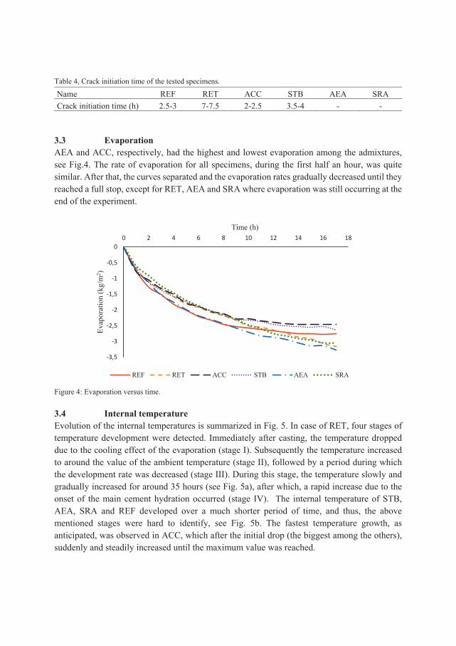
Table 4, Crack initiation time of the tested specimens.
Name REF RET ACC STB AEA SRA Crack initiation time (h) 2.5-3 7-7.5 2-2.5 3.5-4 - -
3.3 Evaporation AEA and ACC, respectively, had the highest and lowest evaporation among the admixtures, see Fig.4. The rate of evaporation for all specimens, during the first half an hour, was quite similar. After that, the curves separated and the evaporation rates gradually decreased until they reached a full stop, except for RET, AEA and SRA where evaporation was still occurring at the end of the experiment.
Figure 4: Evaporation versus time.
3.4 Internal temperature Evolution of the internal temperatures is summarized in Fig. 5. In case of RET, four stages of temperature development were detected. Immediately after casting, the temperature dropped due to the cooling effect of the evaporation (stage I). Subsequently the temperature increased to around the value of the ambient temperature (stage II), followed by a period during which the development rate was decreased (stage III). During this stage, the temperature slowly and gradually increased for around 35 hours (see Fig. 5a), after which, a rapid increase due to the onset of the main cement hydration occurred (stage IV). The internal temperature of STB, AEA, SRA and REF developed over a much shorter period of time, and thus, the above mentioned stages were hard to identify, see Fig. 5b. The fastest temperature growth, as anticipated, was observed in ACC, which after the initial drop (the biggest among the others), suddenly and steadily increased until the maximum value was reached.
-3,5
-3
-2,5
-2
-1,5
-1
-0,5
00 2 4 6 8 10 12 14 16 18
Evap
orat
ion
(kg/
m2 )
Time (h)
REF RET ACC STB AEA SRA
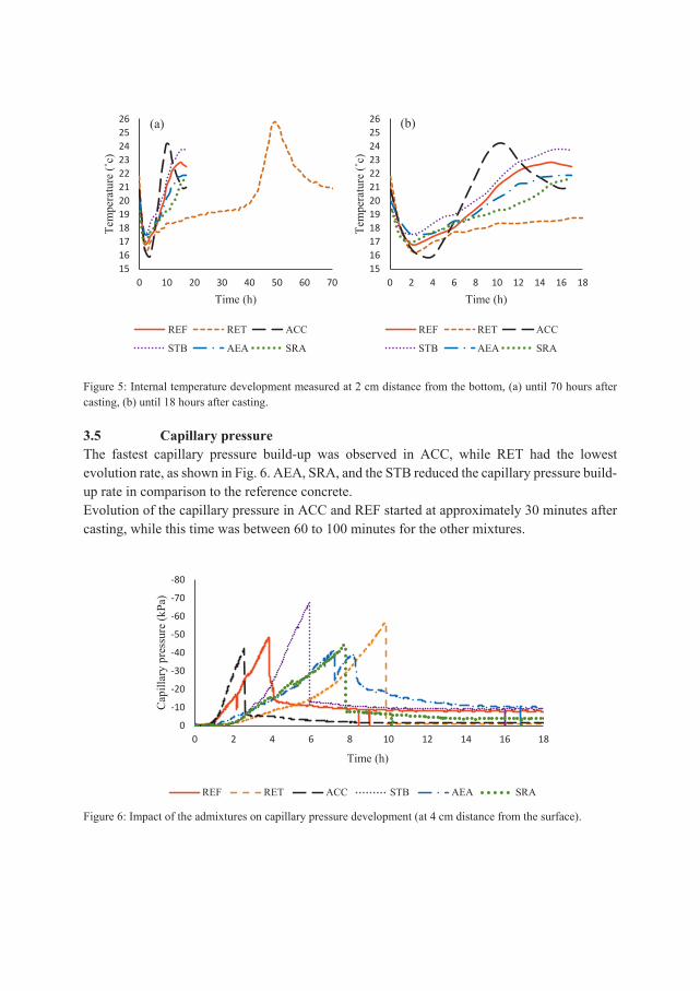
Figure 5: Internal temperature development measured at 2 cm distance from the bottom, (a) until 70 hours after casting, (b) until 18 hours after casting.
3.5 Capillary pressure The fastest capillary pressure build-up was observed in ACC, while RET had the lowest evolution rate, as shown in Fig. 6. AEA, SRA, and the STB reduced the capillary pressure build-up rate in comparison to the reference concrete. Evolution of the capillary pressure in ACC and REF started at approximately 30 minutes after casting, while this time was between 60 to 100 minutes for the other mixtures.
Figure 6: Impact of the admixtures on capillary pressure development (at 4 cm distance from the surface).
-80
-70
-60
-50
-40
-30
-20
-10
00 2 4 6 8 10 12 14 16 18
Cap
illar
y pr
essu
re (k
Pa)
Time (h)
REF RET ACC STB AEA SRA
151617181920212223242526
0 10 20 30 40 50 60 70
Tem
pera
ture
(˚c)
Time (h)
REF RET ACC
STB AEA SRA
(a)
151617181920212223242526
0 2 4 6 8 10 12 14 16 18
Tem
pera
ture
(˚c)
Time (h)
REF RET ACC
STB AEA SRA
(b)
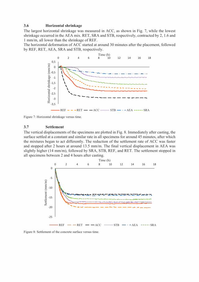
3.6 Horizontal shrinkage The largest horizontal shrinkage was measured in ACC, as shown in Fig. 7, while the lowest shrinkage occurred in the AEA mix. RET, SRA and STB, respectively, contracted by 2, 1.6 and 1 mm/m, all lower than the shrinkage of REF. The horizontal deformation of ACC started at around 30 minutes after the placement, followed by REF, RET, AEA, SRA and STB, respectively.
Figure 7: Horizontal shrinkage versus time. 3.7 Settlement The vertical displacements of the specimens are plotted in Fig. 8. Immediately after casting, the surface settled at a constant and similar rate in all specimens for around 45 minutes, after which the mixtures began to act differently. The reduction of the settlement rate of ACC was faster and stopped after 2 hours at around 13.5 mm/m. The final vertical displacement in AEA was slightly higher (14 mm/m), followed by SRA, STB, REF, and RET. The settlement stopped in all specimens between 2 and 4 hours after casting.
Figure 8: Settlement of the concrete surface versus time.
-3,5
-3
-2,5
-2
-1,5
-1
-0,5
0
0,50 2 4 6 8 10 12 14 16 18
Hor
izon
tal s
hrin
kage
(mm
/m)
Time (h)
REF RET ACC STB AEA SRA
-25
-20
-15
-10
-5
00 2 4 6 8 10 12 14 16 18
Settl
emen
t (m
m/m
)
Time (h)
REF RET ACC STB AEA SRA
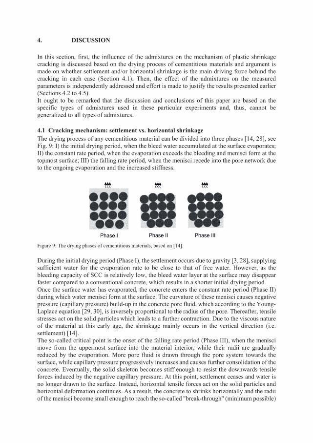
4. DISCUSSION In this section, first, the influence of the admixtures on the mechanism of plastic shrinkage cracking is discussed based on the drying process of cementitious materials and argument is made on whether settlement and/or horizontal shrinkage is the main driving force behind the cracking in each case (Section 4.1). Then, the effect of the admixtures on the measured parameters is independently addressed and effort is made to justify the results presented earlier (Sections 4.2 to 4.5). It ought to be remarked that the discussion and conclusions of this paper are based on the specific types of admixtures used in these particular experiments and, thus, cannot be generalized to all types of admixtures. 4.1 Cracking mechanism: settlement vs. horizontal shrinkage The drying process of any cementitious material can be divided into three phases [14, 28], see Fig. 9: I) the initial drying period, when the bleed water accumulated at the surface evaporates; II) the constant rate period, when the evaporation exceeds the bleeding and menisci form at the topmost surface; III) the falling rate period, when the menisci recede into the pore network due to the ongoing evaporation and the increased stiffness.
Figure 9: The drying phases of cementitious materials, based on [14].
During the initial drying period (Phase I), the settlement occurs due to gravity [3, 28], supplying sufficient water for the evaporation rate to be close to that of free water. However, as the bleeding capacity of SCC is relatively low, the bleed water layer at the surface may disappear faster compared to a conventional concrete, which results in a shorter initial drying period. Once the surface water has evaporated, the concrete enters the constant rate period (Phase II) during which water menisci form at the surface. The curvature of these menisci causes negative pressure (capillary pressure) build-up in the concrete pore fluid, which according to the Young-Laplace equation [29, 30], is inversely proportional to the radius of the pore. Thereafter, tensile stresses act on the solid particles which leads to a further contraction. Due to the viscous nature of the material at this early age, the shrinkage mainly occurs in the vertical direction (i.e. settlement) [14]. The so-called critical point is the onset of the falling rate period (Phase III), when the menisci move from the uppermost surface into the material interior, while their radii are gradually reduced by the evaporation. More pore fluid is drawn through the pore system towards the surface, while capillary pressure progressively increases and causes further consolidation of the concrete. Eventually, the solid skeleton becomes stiff enough to resist the downwards tensile forces induced by the negative capillary pressure. At this point, settlement ceases and water is no longer drawn to the surface. Instead, horizontal tensile forces act on the solid particles and horizontal deformation continues. As a result, the concrete to shrinks horizontally and the radii of the menisci become small enough to reach the so-called "break-through" (minimum possible)
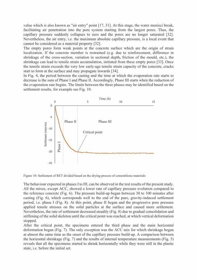
value which is also known as "air entry" point [17, 31]. At this stage, the water menisci break, facilitating air penetration into the pore system starting from the largest pores. Thus, the capillary pressure suddenly collapses to zero and the pores are no longer saturated [32]. Nevertheless, the air entry, i.e. the maximum absolute capillary pressure, is a local event that cannot be considered as a material property [32]. The empty pores form weak points at the concrete surface which are the origin of strain localization. If the concrete member is restrained (e.g. due to reinforcement, difference in shrinkage of the cross-section, variation in sectional depth, friction of the mould, etc.), the shrinkage can lead to tensile strain accumulation, initiated from these empty pores [33]. Once the tensile strain exceeds the very low early-age tensile strain capacity of the concrete, cracks start to form at the surface and may propagate inwards [34]. In Fig. 4, the period between the casting and the time at which the evaporation rate starts to decrease is the sum of Phase I and Phase II. Accordingly, Phase III starts when the reduction of the evaporation rate begins. The limits between the three phases may be identified based on the settlement results, for example see Fig. 10.
Figure 10: Settlement of RET divided based on the drying process of cementitious materials The behaviour expected in phases I to III, can be observed in the test results of the present study. All the mixes, except ACC, showed a lower rate of capillary pressure evolution compared to the reference concrete (Fig. 6). The pressure build-up began between 30 to 100 minutes after casting (Fig. 6), which corresponds well to the end of the pure, gravity-induced settlement period, i.e. phase I (Fig. 8). At this point, phase II began and the progressive pore pressure applied tensile stresses on the solid particles at the surface and caused more settlement. Nevertheless, the rate of settlement decreased steadily (Fig. 8) due to gradual consolidation and stiffening of the solid skeleton until the critical point was reached, at which vertical deformation stopped. After the critical point, the specimens entered the third phase and the main horizontal deformation began (Fig. 7). The only exception was the ACC mix for which shrinkage began at almost the same time as the onset of the capillary pressure build-up. A comparison between the horizontal shrinkage (Fig. 7) and the results of internal temperature measurements (Fig. 5) reveals that all the specimens started to shrink horizontally while they were still in the plastic state, i.e. before the initial set.
-25
-20
-15
-10
-5
00 5 10 15
Settl
emnt
(mm
/m)
Time (h)
Critical point
Phas
e I
Phase II Phase III
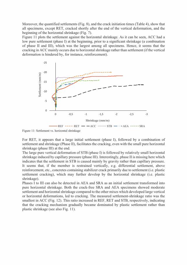
Moreover, the quantified settlements (Fig. 8), and the crack initiation times (Table 4), show that all specimens, except RET, cracked shortly after the end of the vertical deformation, and the beginning of the horizontal shrinkage (Fig. 7). Figure 11 plots the settlement against the horizontal shrinkage. As it can be seen, ACC had a low pure settlement (phase I) at the beginning, prior to a significant shrinkage (a combination of phase II and III), which was the largest among all specimens. Hence, it seems that the cracking in ACC mainly occurs due to horizontal shrinkage rather than settlement (if the vertical deformation is hindered by, for instance, reinforcement).
Figure 11: Settlement vs. horizontal shrinkage For RET, it appears that a large initial settlement (phase I), followed by a combination of settlement and shrinkage (Phase II), facilitates the cracking, even with the small pure horizontal shrinkage (phase III) at the end. The large pure vertical deformation of STB (phase I) is followed by relatively small horizontal shrinkage induced by capillary pressure (phase III). Interestingly, phase II is missing here which indicates that the settlement in STB is caused mainly by gravity rather than capillary pressure. It seems that, if the member is restrained vertically, e.g. differential settlement, above reinforcement, etc., concretes containing stabilizer crack primarily due to settlement (i.e. plastic settlement cracking), which may further develop by the horizontal shrinkage (i.e. plastic shrinkage). Phases I to III can also be detected in AEA and SRA as an initial settlement transformed into pure horizontal shrinkage. Both the crack-free SRA and AEA specimens showed moderate settlement and horizontal shrinkage compared to the other mixes which developed large vertical or horizontal deformations, led to cracking. The measured settlement-shrinkage ratio was the smallest in ACC (Fig. 12). This ratio increased in REF, RET and STB, respectively, indicating that the cracking mechanism gradually became dominated by plastic settlement rather than plastic shrinkage (see also Fig. 11).
-25
-20
-15
-10
-5
0-3-2,5-2-1,5-1-0,50
Settl
emen
t (m
m/m
)
Shrinkage (mm/m)
REF RET ACC STB AEA SRA
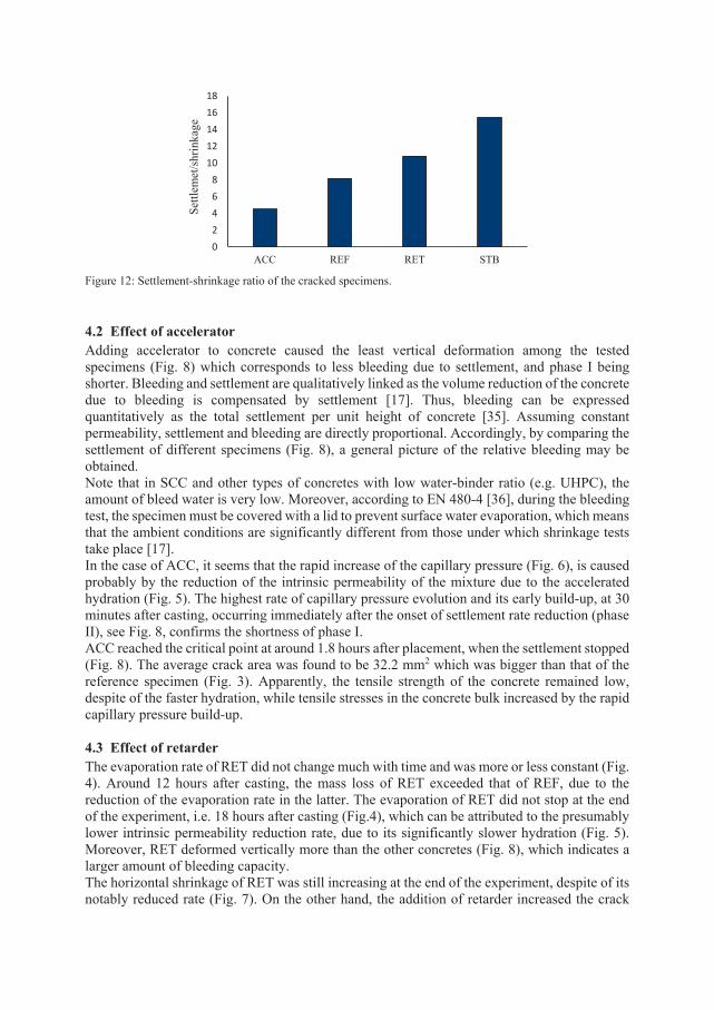
Figure 12: Settlement-shrinkage ratio of the cracked specimens. 4.2 Effect of accelerator Adding accelerator to concrete caused the least vertical deformation among the tested specimens (Fig. 8) which corresponds to less bleeding due to settlement, and phase I being shorter. Bleeding and settlement are qualitatively linked as the volume reduction of the concrete due to bleeding is compensated by settlement [17]. Thus, bleeding can be expressed quantitatively as the total settlement per unit height of concrete [35]. Assuming constant permeability, settlement and bleeding are directly proportional. Accordingly, by comparing the settlement of different specimens (Fig. 8), a general picture of the relative bleeding may be obtained. Note that in SCC and other types of concretes with low water-binder ratio (e.g. UHPC), the amount of bleed water is very low. Moreover, according to EN 480-4 [36], during the bleeding test, the specimen must be covered with a lid to prevent surface water evaporation, which means that the ambient conditions are significantly different from those under which shrinkage tests take place [17]. In the case of ACC, it seems that the rapid increase of the capillary pressure (Fig. 6), is caused probably by the reduction of the intrinsic permeability of the mixture due to the accelerated hydration (Fig. 5). The highest rate of capillary pressure evolution and its early build-up, at 30 minutes after casting, occurring immediately after the onset of settlement rate reduction (phase II), see Fig. 8, confirms the shortness of phase I. ACC reached the critical point at around 1.8 hours after placement, when the settlement stopped (Fig. 8). The average crack area was found to be 32.2 mm2 which was bigger than that of the reference specimen (Fig. 3). Apparently, the tensile strength of the concrete remained low, despite of the faster hydration, while tensile stresses in the concrete bulk increased by the rapid capillary pressure build-up.
4.3 Effect of retarder The evaporation rate of RET did not change much with time and was more or less constant (Fig. 4). Around 12 hours after casting, the mass loss of RET exceeded that of REF, due to the reduction of the evaporation rate in the latter. The evaporation of RET did not stop at the end of the experiment, i.e. 18 hours after casting (Fig.4), which can be attributed to the presumably lower intrinsic permeability reduction rate, due to its significantly slower hydration (Fig. 5). Moreover, RET deformed vertically more than the other concretes (Fig. 8), which indicates a larger amount of bleeding capacity. The horizontal shrinkage of RET was still increasing at the end of the experiment, despite of its notably reduced rate (Fig. 7). On the other hand, the addition of retarder increased the crack
02468
1012141618
ACC REF RET STB
Settl
emet
/shr
inka
ge
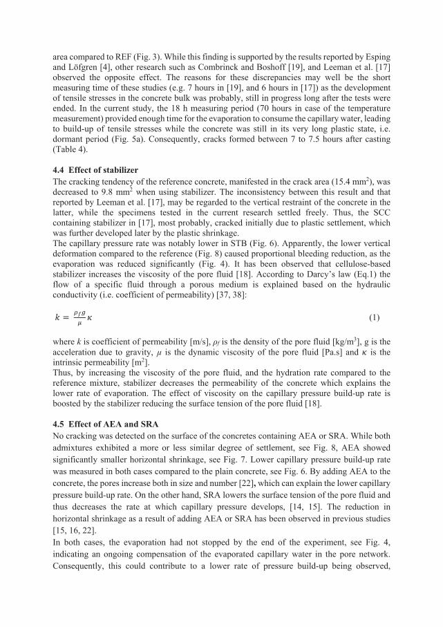
area compared to REF (Fig. 3). While this finding is supported by the results reported by Esping and Löfgren [4], other research such as Combrinck and Boshoff [19], and Leeman et al. [17] observed the opposite effect. The reasons for these discrepancies may well be the short measuring time of these studies (e.g. 7 hours in [19], and 6 hours in [17]) as the development of tensile stresses in the concrete bulk was probably, still in progress long after the tests were ended. In the current study, the 18 h measuring period (70 hours in case of the temperature measurement) provided enough time for the evaporation to consume the capillary water, leading to build-up of tensile stresses while the concrete was still in its very long plastic state, i.e. dormant period (Fig. 5a). Consequently, cracks formed between 7 to 7.5 hours after casting (Table 4). 4.4 Effect of stabilizer The cracking tendency of the reference concrete, manifested in the crack area (15.4 mm2), was decreased to 9.8 mm2 when using stabilizer. The inconsistency between this result and that reported by Leeman et al. [17], may be regarded to the vertical restraint of the concrete in the latter, while the specimens tested in the current research settled freely. Thus, the SCC containing stabilizer in [17], most probably, cracked initially due to plastic settlement, which was further developed later by the plastic shrinkage. The capillary pressure rate was notably lower in STB (Fig. 6). Apparently, the lower vertical deformation compared to the reference (Fig. 8) caused proportional bleeding reduction, as the evaporation was reduced significantly (Fig. 4). It has been observed that cellulose-based stabilizer increases the viscosity of the pore fluid [18]. According to Darcy’s law (Eq.1) the flow of a specific fluid through a porous medium is explained based on the hydraulic conductivity (i.e. coefficient of permeability) [37, 38]: 𝑘𝑘 = 𝜌𝜌𝑓𝑓𝑔𝑔
𝜇𝜇𝜅𝜅 (1)
where k is coefficient of permeability [m/s], ρf is the density of the pore fluid [kg/m3], g is the acceleration due to gravity, µ is the dynamic viscosity of the pore fluid [Pa.s] and 𝜅𝜅 is the intrinsic permeability [m2]. Thus, by increasing the viscosity of the pore fluid, and the hydration rate compared to the reference mixture, stabilizer decreases the permeability of the concrete which explains the lower rate of evaporation. The effect of viscosity on the capillary pressure build-up rate is boosted by the stabilizer reducing the surface tension of the pore fluid [18]. 4.5 Effect of AEA and SRA No cracking was detected on the surface of the concretes containing AEA or SRA. While both admixtures exhibited a more or less similar degree of settlement, see Fig. 8, AEA showed significantly smaller horizontal shrinkage, see Fig. 7. Lower capillary pressure build-up rate was measured in both cases compared to the plain concrete, see Fig. 6. By adding AEA to the concrete, the pores increase both in size and number [22], which can explain the lower capillary pressure build-up rate. On the other hand, SRA lowers the surface tension of the pore fluid and thus decreases the rate at which capillary pressure develops, [14, 15]. The reduction in horizontal shrinkage as a result of adding AEA or SRA has been observed in previous studies [15, 16, 22]. In both cases, the evaporation had not stopped by the end of the experiment, see Fig. 4, indicating an ongoing compensation of the evaporated capillary water in the pore network. Consequently, this could contribute to a lower rate of pressure build-up being observed,
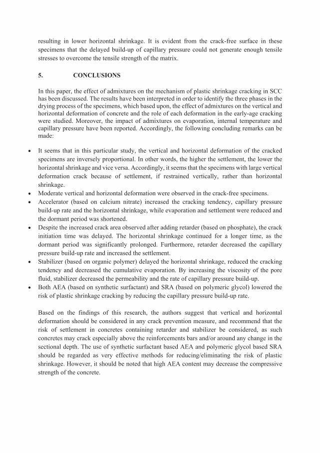
resulting in lower horizontal shrinkage. It is evident from the crack-free surface in these specimens that the delayed build-up of capillary pressure could not generate enough tensile stresses to overcome the tensile strength of the matrix. 5. CONCLUSIONS In this paper, the effect of admixtures on the mechanism of plastic shrinkage cracking in SCC has been discussed. The results have been interpreted in order to identify the three phases in the drying process of the specimens, which based upon, the effect of admixtures on the vertical and horizontal deformation of concrete and the role of each deformation in the early-age cracking were studied. Moreover, the impact of admixtures on evaporation, internal temperature and capillary pressure have been reported. Accordingly, the following concluding remarks can be made:
• It seems that in this particular study, the vertical and horizontal deformation of the cracked specimens are inversely proportional. In other words, the higher the settlement, the lower the horizontal shrinkage and vice versa. Accordingly, it seems that the specimens with large vertical deformation crack because of settlement, if restrained vertically, rather than horizontal shrinkage.
• Moderate vertical and horizontal deformation were observed in the crack-free specimens. • Accelerator (based on calcium nitrate) increased the cracking tendency, capillary pressure
build-up rate and the horizontal shrinkage, while evaporation and settlement were reduced and the dormant period was shortened.
• Despite the increased crack area observed after adding retarder (based on phosphate), the crack initiation time was delayed. The horizontal shrinkage continued for a longer time, as the dormant period was significantly prolonged. Furthermore, retarder decreased the capillary pressure build-up rate and increased the settlement.
• Stabilizer (based on organic polymer) delayed the horizontal shrinkage, reduced the cracking tendency and decreased the cumulative evaporation. By increasing the viscosity of the pore fluid, stabilizer decreased the permeability and the rate of capillary pressure build-up.
• Both AEA (based on synthetic surfactant) and SRA (based on polymeric glycol) lowered the risk of plastic shrinkage cracking by reducing the capillary pressure build-up rate. Based on the findings of this research, the authors suggest that vertical and horizontal deformation should be considered in any crack prevention measure, and recommend that the risk of settlement in concretes containing retarder and stabilizer be considered, as such concretes may crack especially above the reinforcements bars and/or around any change in the sectional depth. The use of synthetic surfactant based AEA and polymeric glycol based SRA should be regarded as very effective methods for reducing/eliminating the risk of plastic shrinkage. However, it should be noted that high AEA content may decrease the compressive strength of the concrete.
ACKNOWLEDGMENT The authors gratefully acknowledge the financial support received from the Development Fund of the Swedish Construction Industry, SBUF. Special thanks are also due to the staff of the MCE and Thysell at Luleå University of Technology in general and Mats Petersson in particular for their technical support. Funding: This study was funded by the Development Fund of the Swedish Construction Industry (case number 13401). REFERENCES [1] W. Lerch, Plastic Shrinkage. ACI J. 53 (1957) 797-802.
[2] D. Ravina, R. Shalon, Plastic shrinkage cracking. ACI Mater J. 65 (1968) 282-291.
[3] T.C. Powers, The Properties of Fresh Concrete, John Wiley & Sons, New York, 1968.
[4] O. Esping, I. Löfgren, Cracking due to plastic and autogenous shrinkage-investigation of early age
deformation of self-compacting concrete-experimental study, Technical report, Chalmers University of
Technology, Sweden, 2005.
[5] W.P. Boshoff, R. Combrinck, Modelling the severity of plastic shrinkage cracking in concrete. Cem Concr
Res 48 (2013) 34-39.
[6] A. Sivakumar, M. Santhanam, Experimental methodology to study plastic shrinkage cracks in high strength
concrete. Proceedings of the Conference Measuring, Monitoring and Modeling Concrete Properties.
Springer (2006) 291-296.
[7] I. Löfgren, O. Esping, O. Jensen, P. Lura, K. Kovler, Early age cracking of self-compacting concrete.
International RILEM Conference on Volume Changes of Hardening Concrete: Testing and Mitigation,
Lyngby, (2006) 251-260.
[8] J. Van Dijk, V. Boardman, Plastic shrinkage cracking of concrete. Proceeding of RILEM International
Symposium of Concrete and Reinforced Concrete in Hot Countries (1971) 225-239.
[9] Y. Kasai, K. Vokoyama, I. Matsui, Tensile properties of early-age concrete. Proceedings of Conference on
Mechanical Behaviour of Materials. Japan, (1972) 288-299.
[10] M.D. Cohen, J. Olek, W.T. Dolch, Mechanism of plastic shrinkage cracking in portland cement and
portland cement-silica fume paste and mortar. Cem Concr Res. 20 (1990)103-119.
[11] A. Radocea, A study on the mechanism of plastic shrinkage of cement-based materials. Chalmers
University of Technology, Gothenburg, (1992).
[12] A. Almusallam, M. Abdul-Waris, M. Maslehuddin, A. Al-Gahtani, Placing and shrinkage at extreme
temperatures. Concr Int. 21(1999):75-79.
[13] P.J. Uno, Plastic shrinkage cracking and evaporation formulas. ACI Mater J. 95 (1998) 365-375
[14] P. Lura, B. Pease, G.B. Mazzotta, F. Rajabipour, J. Weiss, Influence of shrinkage-reducing admixtures on
development of plastic shrinkage cracks. ACI Mater J. 104 (2007) 187.
[15] J. Mora-Ruacho, R. Gettu, A. Aguado, Influence of shrinkage-reducing admixtures on the reduction of
plastic shrinkage cracking in concrete. Cem Concr Res. 39 (2009) 141–146
[16] J. Saliba, E. Rozière, F. Grondin, A. Loukili, Influence of shrinkage-reducing admixtures on plastic and
long-term shrinkage. Cem Concr Compos. 33 (2011) 209–217
[17] A. Leemann, P. Nygaard, P. Lura, Impact of admixtures on the plastic shrinkage cracking of self-
compacting concrete. Cem Concr Compos. 46 (2014)1-7.
[18] S.T. Lin, R. Haung, Effect of viscosity modifying agent on plastic shrinkage cracking of cementitious
composites, Mater Struct. 43 (2010) 651–664
[19] R. Combrinck, W.P. Boshoff, Typical plastic shrinkage cracking behaviour of concrete. Mag Concr Res.
65(2013) 486-493.
[20] S. Ghourchian, M. Wyrzykowski, L. Baquerizo, P. Lura, Performance of passive methods in plastic shrinkage cracking mitigation. Cement and Concrete Composites. 1(2018)148-55.
[21] O. Esping, I. Löfgren, J. Marchand, B. Bissonnette, R. Gagné, M. Jolin, Investigation of early age
deformation in self-compacting concrete. Proceedings of the 2nd International Symposium on Advances in
Concrete Science, Quebec, (2006).
[22] A. Kronlöf, M. Leivo, P. Sipari, Experimental study on the basic phenomena of shrinkage and cracking of
fresh mortar. Cem Concr Res. 25(1995) 1747-1754.
[23] R. Combrinck, M. Kayondo, B.D. le Roux, W.I. de Villiers, W.P. Boshoff, Effect of various liquid
admixtures on cracking of plastic concrete. Cons Build Mater, 202 (2019) 139–153.
[24] EN 197-1, Cement: Composition, Specifications and Conformity Criteria for Common Cements, Br. Stand.
Inst. London. 2000.
[25] R. Johansen, P. Dahl, Control of plastic shrinkage of cement. Proceedings of the 18th Conference on Our
World in Concrete and Structures, Singapore. (1993).
[26] ASTM C1579-13, Standard Test Method for Evaluating Plastic Shrinkage Cracking of Restrained Fiber
Reinforced Concrete (Using a Steel Form Insert), ASTM Int. West Conshohocken, PA, 2013.
[27] EN 12350e12352, Testing Fresh Concrete: Slump Test, Br. Stand. Inst, London. 2000. [28] C.J. Brinker, G.W. Scherer, Sol-Gel Science, Academic Press, New York, 1990, pp. 407-513.
[29] F. Sayahi, Plastic Shrinkage Cracking in Concrete, Licentiate thesis, Luleå University of Technology, 2016.
[30] F.H. Wittmann, On the action of capillary pressure on fresh concrete, Cem Concr Res. 6 (1976) 49-56. [31] F. Sayahi, M. Emborg, H. Hedlund, Plastic shrinkage cracking in concrete: State of the art. J Nord Concr
Res, 51(2014) 95-16. [32] V. Slowik, M. Schmidt, R. Fritzsch, Capillary pressure in fresh cement-based materials and identification
of the air entry value. Cem Concr Compos. 30(2008) 557-565.
[33] V. Slowik, M. Schmidt, Early age cracking and capillary pressure controlled concrete curing. Adv Cem-
Based Mater (2009) 229-234.
[34] F. Sayahi, M. Emborg, H. Hedlund, L. Löfgren, Plastic shrinkage cracking in self-compacting concrete: A
parametric study, International RILEM conference on Materials, Systems and Structures in Civil
Engineering, MSSCE (2016) 609-619.
[35] A.M Neville, J.J. Brooks. Concrete Technology. Longman, London. 1990.
[36] BS EN 480-4, Determination of concrete bleeding, Br. Stand. Inst. London. 1997. [37] D.G. Fredlund, H. Rahardjo, Soil Mechanics for Unsaturated Soils, John Wiley & Sons, 1993.
[38] R. Lal, M.K. Shukla, Principles of Soil Physics, CRC Press, 2004.
PAPER III: Effect of Steel Fibres Extracted from Recycled Tyres on Plastic Shrinkage Cracking of Self-Compacting Concrete Sayahi, F., Emborg, M., Hedlund, H., and Cwirzen, A., Submitted.

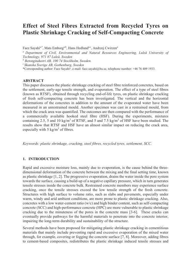
Effect of Steel Fibres Extracted from Recycled Tyres on Plastic Shrinkage Cracking of Self-Compacting Concrete Faez Sayahia,*, Mats Emborga,b, Hans Hedlunda,c, Andrzej Cwirzena
a Department of Civil, Environmental and Natural Resources Engineering, Luleå University of Technology, 971 87 Luleå, Sweden b Betongindustri AB, 100 74 Stockholm, Sweden. c Skanska Sverige AB, Gothenburg, Sweden *Corresponding author: Faez Sayahia, e-mail: [email protected], telephone number: +46 76 409 1933. ABSTRACT This paper discusses the plastic shrinkage cracking of steel fibre reinforced concretes, based on the settlement, early-age tensile strength, and evaporation. The effect of a type of steel fibres (known as RTSF), obtained through recycling end-of-life tyres, on plastic shrinkage cracking of fresh self-compacting concrete has been investigated. The vertical and the horizontal deformations of the concretes in addition to the amount of the evaporated water have been measured in an unrestrained mould. Another specimen was cast in a restrained mould, from which the crack area was quantified. The outcomes are then compared with the performance of a commercially available hooked steel fibre (HSF). During the experiments, mixtures containing 2.5, 5 and 10 kg/m3 of RTSF, and 5 and 7.5 kg/m3 of HSF have been studied. The results show that RTSF and HSF have an almost similar impact on reducing the crack area, especially with 5 kg/m3 of fibres.
Keywords: plastic shrinkage, cracking, steel fibres, recycled tyres, settlement, SCC.
1. INTRODUCTION Rapid and excessive moisture loss, mainly due to evaporation, is the cause behind the three-dimensional deformation of the concrete between the mixing and the final setting time, known as plastic shrinkage [1, 2]. The progressive evaporation, drains the water inside the pore system towards the surface, causing a build-up of a negative capillary pressure, which in turn generates tensile stresses inside the concrete bulk. Restrained concrete members may experience surface cracking, once the tensile stresses exceed the low tensile strength of the fresh concrete. Structures with high surface to volume ratio, such as slabs and pavements, especially under warm, windy and arid ambient conditions, are more prone to plastic shrinkage cracking. Also, concretes with a low water-cement ratio (w/c) and high binder content, such as self-compacting concrete (SCC) and high-performance concrete (HPC) are more vulnerable to plastic shrinkage cracking due to the minuteness of the pores in the concrete mass [3-6]. These cracks can eventually provide pathways for the harmful materials to penetrate into the concrete interior, impairing the long-term durability and sustainability of the structure.
Several methods have been proposed for mitigating plastic shrinkage cracking in cementitious materials that mainly include preventing rapid and excessive evaporation of the mixed water through, for example, covering or fogging the concrete surface [7, 8]. Moreover, adding fibres to cement-based composites, redistributes the plastic shrinkage induced tensile stresses and
leads to more but narrower cracks [9]. Fibre reinforced concrete (FRC) is characterized by higher tensile and flexural strength and lower cracking tendency [10, 11]. Recent research has shown that the efficiency of fibres in reducing the shrinkage induced cracks highly depends on the fibre content [11], material [3, 12], mechanical properties [11, 13] and geometry [14-16].
Plastic shrinkage cracking of FRC has been widely investigated. For instance, Sivakumar and Santhanam [10] quantitatively studied the impact of steel and hybrid fibres (combination of steel and non-metallic fibres such as polyester, polypropylene, and glass) on plastic shrinkage cracking of HPC containing silica fume. They concluded that the hybrid fibres were more effective in mitigating the cracks, among which, the combination of steel and polyester fibres showed the best result [10]. Mangat and Azari [17] investigated the plastic shrinkage of steel fibre reinforced concrete (SFRC). They evaluated the effect of melt extract, hooked, and crimped steel fibres on the cracking of plastic concretes with cement content ranging between 370 kg/m3 to 468 kg/m3. The results showed that the crimped fibres performed more effectively than the melt extract and hooked fibres in restraining the shrinkage, due to their better anchorage characteristics [17].
In addition to commercially available fibres, some studies have shown that various types of recycled fibres can also mitigate plastic shrinkage cracking of cementitious materials [11, 15, 16, 18, 19]. For instance, Bertelsen et al. [11] investigated the effect of recycled polyethylene (R-PE) fibres obtained from discarded fishing nets on plastic shrinkage cracking of restrained mortar overlays on a concrete substrate. It was observed that the addition of 2.0 % of the total volume of R-PE fibres, decreased the total crack area by around 85 %, compared to the reference specimen [11]. Borg et al. [16] studied the performance of a concrete reinforced with fibres produced from waste non-biodegradable plastic, polyethylene terephthalate (PET), directly shredded from collected waste plastic bottles. They concluded that utilizing this type of fibres as reinforcement can improve the concrete resistance against cracking [16]. Considering the eco-friendly aspect of using recycled fibres, in addition to their low price and broad availability, the usage of this type of fibres in the construction sector is gradually increasing [11, 20, 21]. One of the most common and broadly available waste materials that can be recycled to fibres are tyres. Serdar et al. [22] compared the performance of recycled polymer fibres obtained from end-of-life tyres, known as RTPF, with that of commercially available polypropylene fibres, in controlling autogenous shrinkage of concrete. They observed that similar shrinkage behaviour could be achieved if the polypropylene fibres are replaced by a higher amount of recycled tyre polymer fibres [22]. However, the RTPF used in this study was not totally clean from rubber and that is probably the reason of the reduced effectiveness reported. Research [23-32] show that using recycled tyres steel fibres (RTSF), mechanically recovered by shredding waste tyres [24], as reinforcement increases strength, ductility and toughness of the concrete. However, the effect of this type of fibres on plastic shrinkage cracking in concrete has never been investigated. Thus, in the present paper, an effort is made to fill this knowledge gap by studying this aspect of RTSF. The results are then compared with a type of a commercially available hooked steel fibre (HSF).
The significance of this research is that the cracking process is discussed, not only based on the tensile strength of FRC and the measured deformations, but also based on the concrete bleeding capacity and mass loss. The cracking behaviour of the specimens are, thus, justified based on the available cracking severity models.
Moreover, the positive effect of the waste management of end-of-life tyres on the environment has become seriously noticed, especially by the European Union (EU), where it is estimated that more than 500,000 tonnes of high-quality steel fibres can be extracted annually [24]. Hence, the present research may expand the applications of RTSF in the construction sector (already in use by the concrete industry in the slab on grade construction for shrinkage control), which eventually can lead to the replacement of the currently available fibres. 2. EXPERIMENTAL PROGRAMME 2.1 Materials and mixing process The mix designs of the tested concretes and the composition of the cement are presented, respectively, in Table 1 and Table 2. The mix design of the fibre reinforced mixtures was the same as that of the reference concrete. The only difference was the amount of the added fibres. The mixtures were produced using a Portland cement (CEM I 42.5N – SR 3 MH/LA according to EN 197-1) [33], known as Anläggningscement Degerhamn in Sweden. The w/c ratio was set to 0.55, and the mixtures contained 56% by total aggregate mass of crushed 0-4 mm and 44% by total aggregate mass of mixed natural/crushed 8-16 mm aggregates. The superplasticizer (SP), based on polycarboxylate ether and commercially known as Sikament 56 in Sweden, had a density of 1080 ± 0.02 kg/m3 and a solid content of 37 ± 1 wt%. The added limestone filler (Limus 40) had a density of 2700 kg/m3. Table 1, Mix design and the fibre content of the concretes.
Mixture Cement (kg/m3)
Water (kg/m3)
Agg. 0-4 (kg/m3)
Agg. 8-16 (kg/m3)
Filler (kg/m3)
SP (kg/m3) w/c
REF 340 187 1021 802 160 3.4 0.55 Fibre dosage (kg/m3) RTSF HSF
RTSF 2.5 2.5 - RTSF 5 5 - RTSF 10 10 - HSF 5 - 5 HSF 7.5 - 7.5
Table 2. Composition of the used cement (produced by Cementa AB, Sweden).
Name CEM I 42.5N – SR 3 MH/LA (Anläggningscement) Unit
CaO 63.9 % SiO2 21.3 % Al2O3 3.6 % Fe2O3 4.5 % MgO 1.0 % Na2O 0.12 % K2O 0.66 % SO3 2.8 % CI 0.01 % C2S 12.8 % C3S 64.1 % C3A 2.1 % C4AF 13.6 % Density 3189 (kg/m3) Blaine 310 (m2/kg)
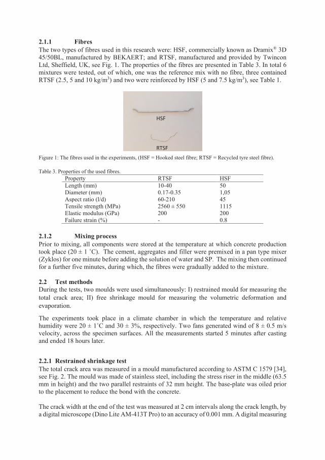
2.1.1 Fibres The two types of fibres used in this research were: HSF, commercially known as Dramix® 3D 45/50BL, manufactured by BEKAERT; and RTSF, manufactured and provided by Twincon Ltd, Sheffield, UK, see Fig. 1. The properties of the fibres are presented in Table 3. In total 6 mixtures were tested, out of which, one was the reference mix with no fibre, three contained RTSF (2.5, 5 and 10 kg/m3) and two were reinforced by HSF (5 and 7.5 kg/m3), see Table 1.
Figure 1: The fibres used in the experiments, (HSF = Hooked steel fibre; RTSF = Recycled tyre steel fibre).
Table 3. Properties of the used fibres.
Property RTSF HSF Length (mm) 10-40 50 Diameter (mm) 0.17-0.35 1,05 Aspect ratio (l/d) 60-210 45 Tensile strength (MPa) 2560 ± 550 1115 Elastic modulus (GPa) 200 200 Failure strain (%) - 0.8
2.1.2 Mixing process Prior to mixing, all components were stored at the temperature at which concrete production took place (20 ± 1 ˚C). The cement, aggregates and filler were premixed in a pan type mixer (Zyklos) for one minute before adding the solution of water and SP. The mixing then continued for a further five minutes, during which, the fibres were gradually added to the mixture. 2.2 Test methods During the tests, two moulds were used simultaneously: I) restrained mould for measuring the total crack area; II) free shrinkage mould for measuring the volumetric deformation and evaporation.
The experiments took place in a climate chamber in which the temperature and relative humidity were 20 ± 1˚C and 30 ± 3%, respectively. Two fans generated wind of 8 ± 0.5 m/s velocity, across the specimen surfaces. All the measurements started 5 minutes after casting and ended 18 hours later.
2.2.1 Restrained shrinkage test The total crack area was measured in a mould manufactured according to ASTM C 1579 [34], see Fig. 2. The mould was made of stainless steel, including the stress riser in the middle (63.5 mm in height) and the two parallel restraints of 32 mm height. The base-plate was oiled prior to the placement to reduce the bond with the concrete. The crack width at the end of the test was measured at 2 cm intervals along the crack length, by a digital microscope (Dino Lite AM-413T Pro) to an accuracy of 0.001 mm. A digital measuring
HSF
RTSF
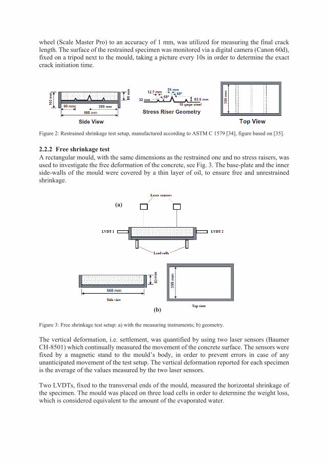
wheel (Scale Master Pro) to an accuracy of 1 mm, was utilized for measuring the final crack length. The surface of the restrained specimen was monitored via a digital camera (Canon 60d), fixed on a tripod next to the mould, taking a picture every 10s in order to determine the exact crack initiation time.
Figure 2: Restrained shrinkage test setup, manufactured according to ASTM C 1579 [34], figure based on [35]. 2.2.2 Free shrinkage test A rectangular mould, with the same dimensions as the restrained one and no stress raisers, was used to investigate the free deformation of the concrete, see Fig. 3. The base-plate and the inner side-walls of the mould were covered by a thin layer of oil, to ensure free and unrestrained shrinkage.
Figure 3: Free shrinkage test setup: a) with the measuring instruments; b) geometry. The vertical deformation, i.e. settlement, was quantified by using two laser sensors (Baumer CH-8501) which continually measured the movement of the concrete surface. The sensors were fixed by a magnetic stand to the mould’s body, in order to prevent errors in case of any unanticipated movement of the test setup. The vertical deformation reported for each specimen is the average of the values measured by the two laser sensors. Two LVDTs, fixed to the transversal ends of the mould, measured the horizontal shrinkage of the specimen. The mould was placed on three load cells in order to determine the weight loss, which is considered equivalent to the amount of the evaporated water.
(a)
(b)
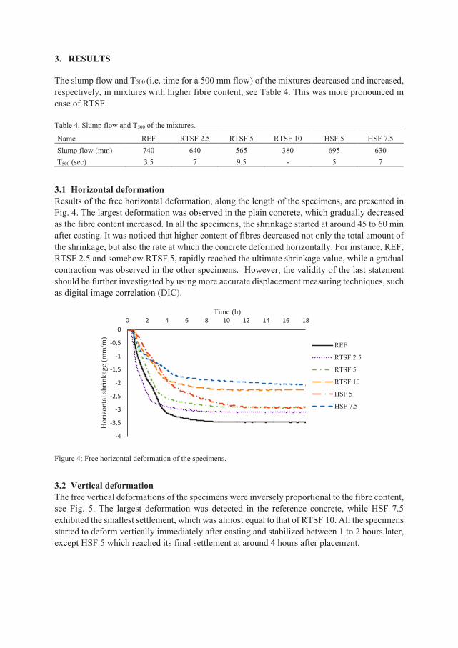
3. RESULTS The slump flow and T500 (i.e. time for a 500 mm flow) of the mixtures decreased and increased, respectively, in mixtures with higher fibre content, see Table 4. This was more pronounced in case of RTSF. Table 4, Slump flow and T500 of the mixtures.
Name REF RTSF 2.5 RTSF 5 RTSF 10 HSF 5 HSF 7.5 Slump flow (mm) 740 640 565 380 695 630 T500 (sec) 3.5 7 9.5 - 5 7
3.1 Horizontal deformation Results of the free horizontal deformation, along the length of the specimens, are presented in Fig. 4. The largest deformation was observed in the plain concrete, which gradually decreased as the fibre content increased. In all the specimens, the shrinkage started at around 45 to 60 min after casting. It was noticed that higher content of fibres decreased not only the total amount of the shrinkage, but also the rate at which the concrete deformed horizontally. For instance, REF, RTSF 2.5 and somehow RTSF 5, rapidly reached the ultimate shrinkage value, while a gradual contraction was observed in the other specimens. However, the validity of the last statement should be further investigated by using more accurate displacement measuring techniques, such as digital image correlation (DIC).
Figure 4: Free horizontal deformation of the specimens.
3.2 Vertical deformation The free vertical deformations of the specimens were inversely proportional to the fibre content, see Fig. 5. The largest deformation was detected in the reference concrete, while HSF 7.5 exhibited the smallest settlement, which was almost equal to that of RTSF 10. All the specimens started to deform vertically immediately after casting and stabilized between 1 to 2 hours later, except HSF 5 which reached its final settlement at around 4 hours after placement.
-4
-3,5
-3
-2,5
-2
-1,5
-1
-0,5
00 2 4 6 8 10 12 14 16 18
Hor
izon
tal s
hrin
kage
(mm
/m)
Time (h)
REF
RTSF 2.5
RTSF 5
RTSF 10
HSF 5
HSF 7.5
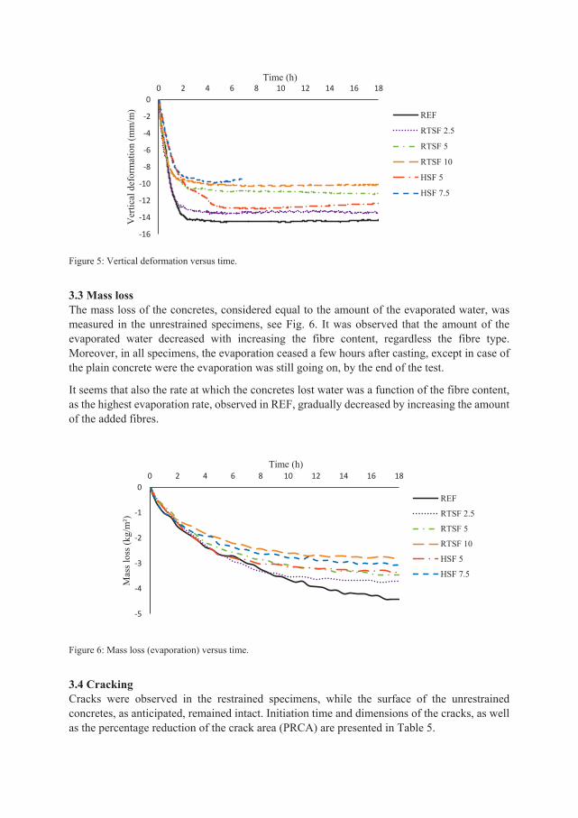
Figure 5: Vertical deformation versus time.
3.3 Mass loss The mass loss of the concretes, considered equal to the amount of the evaporated water, was measured in the unrestrained specimens, see Fig. 6. It was observed that the amount of the evaporated water decreased with increasing the fibre content, regardless the fibre type. Moreover, in all specimens, the evaporation ceased a few hours after casting, except in case of the plain concrete were the evaporation was still going on, by the end of the test.
It seems that also the rate at which the concretes lost water was a function of the fibre content, as the highest evaporation rate, observed in REF, gradually decreased by increasing the amount of the added fibres.
Figure 6: Mass loss (evaporation) versus time.
3.4 Cracking Cracks were observed in the restrained specimens, while the surface of the unrestrained concretes, as anticipated, remained intact. Initiation time and dimensions of the cracks, as well as the percentage reduction of the crack area (PRCA) are presented in Table 5.
-16
-14
-12
-10
-8
-6
-4
-2
00 2 4 6 8 10 12 14 16 18
Ver
tical
def
orm
atio
n (m
m/m
)
Time (h)
REF
RTSF 2.5
RTSF 5
RTSF 10
HSF 5
HSF 7.5
-5
-4
-3
-2
-1
00 2 4 6 8 10 12 14 16 18
Mas
s los
s (kg
/m²)
Time (h)
REF
RTSF 2.5
RTSF 5
RTSF 10
HSF 5
HSF 7.5
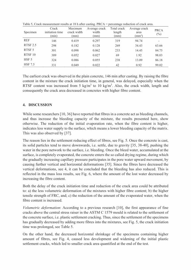
Table 5, Crack measurement results at 18 h after casting. PRCA = percentage reduction of crack area.
Specimen Crack
initiation time (min)
Maximum crack width
(mm)
Average crack width (mm)
Total crack length (mm)
Average crack area
(mm²)
PRCA (%)
REF 146 0.419 0.297 319 94.74 - RTSF 2.5 298 0.182 0.128 269 34.43 63.66 RTSF 5 301 0.098 0.062 233 14.45 84.75 RTSF 10 389 0.052 0.027 69 1.92 98.03 HSF 5 324 0.086 0.055 238 13.09 86.18 HSF 7.5 331 0.049 0.022 42 0.92 99.02
The earliest crack was observed in the plain concrete, 146 min after casting. By raising the fibre content in the mixture the crack initiation time, in general, was delayed, especially when the RTSF content was increased from 5 kg/m3 to 10 kg/m3. Also, the crack width, length and consequently the crack area decreased in concretes with higher fibre content. 4. DISCUSSION While some researchers [10, 36] have reported that fibres in a concrete act as bleeding channels, and thus increase the bleeding capacity of the mixture, the results presented here, show otherwise. The reduction of the initial evaporation rate, when the fibre content is higher, indicates less water supply to the surface, which means a lower bleeding capacity of the matrix. This was also observed by [37].
The reason lies in the settlement reducing effect of fibres, see Fig. 5. Once the concrete is cast, its solid particles tend to move downwards, i.e. settle, due to gravity [35, 38-40], pushing the water in the pore network to the surface, i.e. bleeding. Once the bleed water, accumulated at the surface, is completely evaporated, the concrete enters the so called drying regime, during which the gradually increasing capillary pressure participates in the pore water upward movement, by causing further vertical and horizontal deformations [35]. Since the fibres have decreased the vertical deformations, see 4, it can be concluded that the bleeding has also reduced. This is reflected in the mass loss results, see Fig. 6, where the amount of the lost water decreased by increasing the fibre content.
Both the delay of the crack initiation time and reduction of the crack area could be attributed to: a) the less volumetric deformation of the mixtures with higher fibre content; b) the higher tensile strength of FRC, and; c) the reduction of the amount of the evaporated water, when the fibre content is increased.
Volumetric deformation: According to a previous research [10], the first appearance of fine cracks above the central stress raiser in the ASTM C 1579 mould is related to the settlement of the concrete surface, i.e. plastic settlement cracking. Thus, since the settlement of the specimens has gradually decreased by adding more fibres into the mixtures, see Fig. 5, the crack initiation time was prolonged, see Table 5.
On the other hand, the decreased horizontal shrinkage of the specimens containing higher amount of fibres, see Fig. 4, caused less development and widening of the initial plastic settlement cracks, which led to smaller crack area quantified at the end of the test.
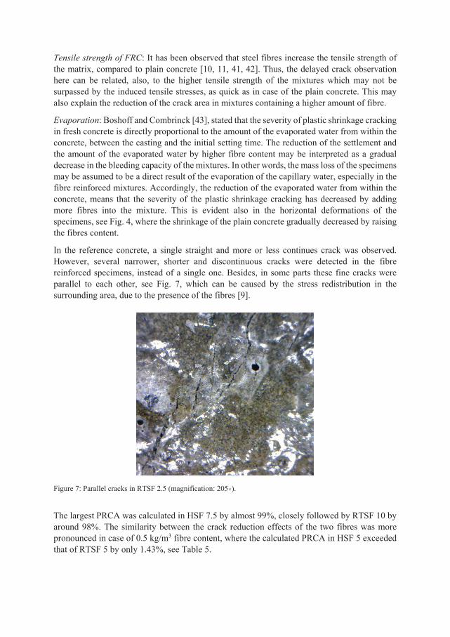
Tensile strength of FRC: It has been observed that steel fibres increase the tensile strength of the matrix, compared to plain concrete [10, 11, 41, 42]. Thus, the delayed crack observation here can be related, also, to the higher tensile strength of the mixtures which may not be surpassed by the induced tensile stresses, as quick as in case of the plain concrete. This may also explain the reduction of the crack area in mixtures containing a higher amount of fibre.
Evaporation: Boshoff and Combrinck [43], stated that the severity of plastic shrinkage cracking in fresh concrete is directly proportional to the amount of the evaporated water from within the concrete, between the casting and the initial setting time. The reduction of the settlement and the amount of the evaporated water by higher fibre content may be interpreted as a gradual decrease in the bleeding capacity of the mixtures. In other words, the mass loss of the specimens may be assumed to be a direct result of the evaporation of the capillary water, especially in the fibre reinforced mixtures. Accordingly, the reduction of the evaporated water from within the concrete, means that the severity of the plastic shrinkage cracking has decreased by adding more fibres into the mixture. This is evident also in the horizontal deformations of the specimens, see Fig. 4, where the shrinkage of the plain concrete gradually decreased by raising the fibres content.
In the reference concrete, a single straight and more or less continues crack was observed. However, several narrower, shorter and discontinuous cracks were detected in the fibre reinforced specimens, instead of a single one. Besides, in some parts these fine cracks were parallel to each other, see Fig. 7, which can be caused by the stress redistribution in the surrounding area, due to the presence of the fibres [9].
Figure 7: Parallel cracks in RTSF 2.5 (magnification: 205×).
The largest PRCA was calculated in HSF 7.5 by almost 99%, closely followed by RTSF 10 by around 98%. The similarity between the crack reduction effects of the two fibres was more pronounced in case of 0.5 kg/m3 fibre content, where the calculated PRCA in HSF 5 exceeded that of RTSF 5 by only 1.43%, see Table 5.
The price of RTSF lies in the same range as fibres of similar characteristics. Moreover, the production of RTSF consumes only 5% of the energy needed for manufacturing same amount of other fibres. Hence, considering the environmentally friendly aspect of RTSF, it seems that it can be a highly efficient and economically justified alternative for the currently available steel fibres in the market.
It ought to be remarked that, RTSF significantly reduces the slump flow of the concrete compared to HSF, see Table 4, which can be a disadvantage when concrete fluidity is desired. However, this can be compensated by increasing the SP dosage in the mixture. 5. CONCLUSIONS In this study, the effect of steel fibres obtained from recycled tyres (RTSF) on plastic shrinkage cracking in fresh concrete, was compared to that of a commercially available hooked steel fibre (HSF). The mixtures were cast in two restrained and unrestrained moulds, in which the former was used to investigate the cracking, while the latter was utilized to measure the amount of the evaporated water, vertical and horizontal deformations of the concrete.
Based on the outcomes of the research the following conclusions can be drawn:
• The crack initiation time and PRCA were, respectively, delayed and increased in the mixtures containing a higher amount of fibres, in comparison to the plain concrete, which can be attributed to the smaller volumetric shrinkage, higher tensile strength of the FRC, and lower amount of evaporated water from within the concrete.
• The settlement was reduced, as the fibre content increased, which can be interpreted as a reduction of the bleeding capacity of the concretes.
• RTSF showed an almost equivalent reduction of the crack area, compared to HSF. The effect was almost identical when the fibre content was 5 kg/m3. However, 10 kg/m3 of RTSF was needed to reach the same PRCA of HSF 7.5.
• Both RTSF and HSF reduced the slump flow of the concrete. Nevertheless, the fluidity reduction, caused by RTSF, was more notable compared to HSF.
• Increasing the fibre content, decreased both the settlement and horizontal shrinkage of the mixtures, regardless of the fibre type.
ACKNOWLEDGMENT
The authors would like to gratefully appreciate the financial support they received from the Development Fund of the Swedish Construction Industry, SBUF. Special thanks are also due to Prof. Kypros Pilakoutas and Dr. Harris Angelakopoulos for their technical support. RTSF was kindly provided by Twincon Ltd, Sheffield, UK. The help, the authors received from the personnel of the MCE and Thysell lab at Luleå University of Technology is sincerely acknowledged.
Funding: This study was funded by the Development Fund of the Swedish Construction Industry (case number 13401).
REFERENCES
1. Lerch. W. (1957) Plastic Shrinkage. ACI Journal 53(8):797-802. 2. Ravina. D. Shalon R (1968) Plastic shrinkage cracking. ACI Journal 65(4):282-291. 3. Balaguru P. Contribution of fibers to crack reduction of cement composites during the
initial and final setting period. ACI Mat J 1994:280–8. 4. Esping, O. and Löfgren, I., "Cracking due to plastic and autogenous shrinkage-
Investigation of early age deformation of self-compacting concrete-Experimental study", Technical report, Chalmers University of Technology, Sweden, 2005.
5. Persson, B.: Plastic shrinkage of self-compacting concrete. In: Jensen, O.M., Geiker, M., Stang, H. (eds.) Proceedings of the Knud Hojgaard Conference, Lyngby, Report R-155 DTU, pp. 43-57 (2005).
6. Gram, H.E., Pentti, P.: Properties of SCC: Especially early age and long term shrinkage and salt frost resistance. In: Skarendahl, Å., Petersson, Ö. (eds.) Proceedings of the 1st In-ternational RILEM Symposium on Self-compacting Concrete, Stockholm, pp. 211-225. RILEM Publications S.A.R.L., Bagneux (1999).
7. Slowik V. Schmidt M (2009) Early age cracking and capillary pressure controlled concrete curing. Advance in Cement-Based Material 229-234.
8. Schmidt M, Slowik V. Instrumentation for optimizing concrete curing. Concrete International. 2013;35(8).
9. Sivakumar A, Santhanam M. Experimental methodology to study plastic shrinkage cracks in high strength concrete. In: Measuring, Monitoring and Modelling Concrete Properties. Springer, 2006. pp. 291-296.
10. Sivakumar A., Santhanam M. A quantitative study on the plastic shrinkage cracking in high strength hybrid fibre reinforced concrete. Cement & Concrete Composites 29 (2007) 575–581.
11. Bertelsen I.M.G., Ottosen, L.M., Fischer G. Quantitative analysis of the influence of synthetic fibres on plastic shrinkage cracking using digital image correlation. Construction and Building Materials 199 (2019) 124–137.
12. A. Mazzoli, S. Monosi, E.S. Plescia, Evaluation of the early-age-shrinkage of Fiber Reinforced Concrete (FRC) using image analysis methods, Constr. Build. Mater. 101 (1) (2015) 596–601.
13. A.E. Naaman, T. Wongtanakitcharoen, G. Hauser, Influence of different fibers on plastic shrinkage cracking of concrete, ACI Mater. J. 102 (1) (2005) 49–58.
14. E. Boghossian, L.D. Wegner, Use of flax fibres to reduce plastic shrinkage cracking in concrete, Cem. Concr. Compos. 30 (10) (2008) 929–937,
15. N. Pešic´, S. Zˇivanovic´ , R. Garcia, P. Papastergiou, Mechanical properties of concrete reinforced with recycled HDPE plastic fibres, Constr. Build. Mater. 115 (2016) 362–370,
16. R.P. Borg, O. Baldacchino, L. Ferrara, Early age performance and mechanical characteristics of recycled PET fibre reinforced concrete, Constr. Build. Mater. 108 (2016) 29–47
17. Mangat P.S., Azari M. M., Plastic shrinkage of steel fibre reinforced concrete. Materials and structures, 23 (1190) 186-195.
18. B.S. Al-Tulaian, M.J. Al-Shannag, A.R. Al-Hozaimy, Recycled plastic waste fibers for reinforcing Portland cement mortar, Constr. Build. Mater. 127 (2016) 102– 110.
19. F.L. Auchey, The use of recycled polymer fibers as secondary reinforcement in concrete structures, J. Constr. Educ. 3 (2) (1998) 131–140.
20. R. Siddique, J. Khatib, I. Kaur, Use of recycled plastic in concrete: a review, Waste Manage. 28 (10) (2008) 1835–1852.
21. L. Gu, T. Ozbakkaloglu, Use of recycled plastics in concrete: a critical review, Waste Manage. 51 (2016) 19–42.
22. M. Serdar, A. Baricˇevic´ , M. Jelcˇic´ Rukavina, M. Pezer, D. Bjegovic´ , N. Štirmer, Shrinkage behaviour of fibre reinforced concrete with recycled tyre polymer fibres, Int. J. Polym. Sci. 2015.3 (2015) 1–9.
23. Jafarifar N., Shrinkage behaviour of steel-fibre-reinforced-concrete pavements. PhD thesis. Department of civil and structural engineering. The University of Sheffield, UK, 2012.
24. Pilakoutas, K., Neocleous, K., Tlemat, H. (2004) Reuse of tyre steel fibres as concrete reinforcement, Proceedings of the ICE: Engineering Sustainability, 157 (3), pp. 131-138.
25. Pilakoutas K., Strube R. (2001), “Reuse of Tyre Fibres in Concrete”, Procs International Symposium Recycling and Re-use of Used Tyres, Dundee, 225-236.
26. Tlemat, H., Pilakoutas, K. & Neocleous, K. (2003a), “Flexural Toughness of SFRC Made with Fibres Extracted from Tyres”, Recycling and Reuse of Waste Materials: Proceedings of International Symposium on Advances in Waste Management and Recycling, Dundee (Thomas Telford Ltd, London), 365–374.
27. Tlemat, H., Pilakoutas, K. & Neocleous, K. (2003b), “Pull-out Behaviour of Steel Fibres Recycled from Used Tyres”, Role of Concrete in Sustainable Development, Proceedings of International Symposia on Celebrating Concrete: People and Practice, Dundee (Thomas Telford Ltd, London), 175–184.
28. Tlemat H. (2004), “Steel Fibres from Waste Tyres to Concrete: Testing, Modelling and Design”, Ph.D. Thesis, Department of Civil and Structural Engineering, University of Sheffield, UK.
29. Tlemat, H., Pilakoutas, K & Neocleous, K. (2006), “Stress-Strain Characteristic of SFRC Using Recycled Fibres”, Materials and Structures 39(3): 365-377.
30. Neocleous K., Tlemat H., Pilakoutas K. (2006), “Design Issues for Concrete Reinforced with Steel Fibres, Including Fibres Recovered from Used Tires”, Journal of Materials in Civil Engineering, ASCE 18(5): 677-685.
31. Graeff A. (2011), “Long-Term Performance of Recycled Steel Fibre Reinforced Concrete for Pavement Applications”, PhD Thesis, University of Sheffield, UK.
32. Graeff A.G., Pilakoutas K., Neocleous K., Peres M.V. (2012), “Fatigue Resistance and Cracking Mechanism of Concrete Pavements Reinforced with Recycled Steel Fibres Recovered from Post-Consumer Tyres”, Engineering Structures 45: 385-395.
33. EN 197-1 (2000), Cement: Composition, Specifications and Conformity Criteria for Common Cements, Br. Stand. Inst. Lond., 2000.
34. ASTM C1579-13, Standard Test Method for Evaluating Plastic Shrinkage Cracking of Restrained Fiber Reinforced Concrete (Using a Steel Form Insert), ASTM Int. West Conshohocken, PA, 2013.
35. P. Lura, B. Pease, G.B. Mazzotta, F. Rajabipour, J. Weiss, Influence of shrinkage-reducing admixtures on development of plastic shrinkage cracks. ACI Mater J. 104 (2007) 187.
36. Zollo RF, Alter J, Bouchacourt B. Plastic and drying shrinkage in concrete containing collated fibrillated polypropylene fibers. In: Proceedings of RILEm third international symposium on development in fiber reinforced cement and concrete 1986, England.
37. Chandramouli K., Srinivasa Rao P., Pannirselvam N., Seshadri Sekhar T., Sravana P.,
Strength properties of glass fibre concrete. Journal of Engineering and Applied Sciences 5 (2010) 1-6.
38. Slowik. V. Schmidt M. Fritzsch R (2008) Capillary pressure in fresh cement-based materials and identification of the air entry value. Journal of Cement and Concrete composites 30(7):557-565.
39. Slowik V. Schmidt M (2009) Early age cracking and capillary pressure controlled concrete curing. Advance in Cement-Based Material 229-234.
40. Sayahi. F. “Plastic Shrinkage Cracking in Concrete”. Licentiate thesis. Luleå University of Technology. 2016.
41. Banthia N, Yan C. Shrinkage cracking in polyolefin fiber-reinforced concrete. ACI Mat J 2000:432–7.
42. Ramakrishnan V. Concrete plastic shrinkage reduction potential of synergy fibers, In: Symposium of the eightieth annual transportation research board meeting, Washington, DC, 2001.
43. Boshoff, W.P., Combrinck, R., Modelling the severity of plastic shrinkage cracking in concrete. Cem Concr Res 48 (2013) 34-39.

PAPER IV: Plastic Shrinkage Cracking of Self-compacting Concrete: Influence of Capillary Pressure and Dormant Period Sayahi, F., Emborg, M., Hedlund, H., and Cwirzen, A., Submitted.

1
Plastic Shrinkage Cracking of Self-compacting Concrete: Influence of Capillary Pressure and Dormant Period
Faez Sayahia, Mats Emborga,b, Hans Hedlunda,c, Andrzej Cwirzena
a Department of Civil, Environmental and Natural Resources Engineering, Luleå University of Technology, 971 87 Luleå, Sweden b Betongindustri AB, 100 74 Stockholm, Sweden. c Skanska AB, 405 18 Gothenburg, Sweden.
Corresponding author: Faez Sayahia, e-mail: [email protected], Tel. number: +46 76 409 1933.
ABSTRACT This research investigates the effect of capillary pressure and the length of the hydration dormant period on the plastic shrinkage cracking tendency of SCC by studying specimens produced with different w/c ratios, cement types and SP dosages. A relationship between the capillary pressure rate and the length of the hydration dormant period is defined, which can explain the cracking severity of the concrete when the volumetric deformation is unknown. The results show, that the cracking tendency of SCC was the lowest in case of w/c ratio between 0.45 and 0.55, finer rapid hardening cement and lower dosage of SP. The dormant period was prolonged by increasing the w/c ratio, using coarser cement and higher SP dosage. It was concluded that the cracking tendency of concrete is a function of the capillary pressure build-up rate and the length of the dormant period. Keywords: plastic shrinkage, cracking, evaporation, capillary pressure, dormant period, self-compacting concrete.
1. INTRODUCTION Plastic shrinkage cracks in concrete may form at the surface shortly after casting and before the concrete gain enough tensile strain capacity [1, 2]. The aesthetics, durability and serviceability of a structure may be dramatically impaired, as cracks facilitate ingress of harmful materials into the concrete that may cause damage in a long term. The physical aspect of plastic shrinkage is manifested in evaporation of the capillary water and the consequent build-up of a hydraulic pressure, i.e. capillary pressure, in the liquid phase of the material [3]. Autogenous shrinkage, during which the pore liquid is consumed by self-desiccation, does not play a decisive role in plastic shrinkage cracking, when water/cement ratio (w/c) is more than 0.5 [4, 5]. However, for concretes with low w/c ratio and/or high cement content, the effect of autogenous shrinkage in early-age cracking should be considered [6]. In this paper, the term "plastic shrinkage" refers to the contraction induced by drying, i.e. evaporation. After placing the concrete in the mould, its solid particles settle due to gravity, forcing the pore water to move upwards to the surface, i.e. bleeding regime [7]. This surface water eventually evaporates, after which menisci start to form inside the pores, i.e. drying regime [7]. At this point, a negative capillary pressure begins to build-up in the pore network, which in turn creates tensile forces applying on the solid particles. If the accumulated tensile stresses exceed the tensile strength of the young concrete, cracks will form [3].
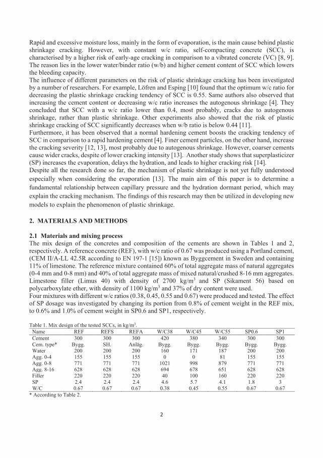
2
Rapid and excessive moisture loss, mainly in the form of evaporation, is the main cause behind plastic shrinkage cracking. However, with constant w/c ratio, self-compacting concrete (SCC), is characterised by a higher risk of early-age cracking in comparison to a vibrated concrete (VC) [8, 9]. The reason lies in the lower water/binder ratio (w/b) and higher cement content of SCC which lowers the bleeding capacity. The influence of different parameters on the risk of plastic shrinkage cracking has been investigated by a number of researchers. For example, Löfren and Esping [10] found that the optimum w/c ratio for decreasing the plastic shrinkage cracking tendency of SCC is 0.55. Same authors also observed that increasing the cement content or decreasing w/c ratio increases the autogenous shrinkage [4]. They concluded that SCC with a w/c ratio lower than 0.4, most probably, cracks due to autogenous shrinkage, rather than plastic shrinkage. Other experiments also showed that the risk of plastic shrinkage cracking of SCC significantly decreases when w/b ratio is below 0.44 [11]. Furthermore, it has been observed that a normal hardening cement boosts the cracking tendency of SCC in comparison to a rapid hardening cement [4]. Finer cement particles, on the other hand, increase the cracking severity [12, 13], most probably due to autogenous shrinkage. However, coarser cements cause wider cracks, despite of lower cracking intensity [13]. Another study shows that superplasticizer (SP) increases the evaporation, delays the hydration, and leads to higher cracking risk [14]. Despite all the research done so far, the mechanism of plastic shrinkage is not yet fully understood especially when considering the evaporation [13]. The main aim of this paper is to determine a fundamental relationship between capillary pressure and the hydration dormant period, which may explain the cracking mechanism. The findings of this research may then be utilized in developing new models to explain the phenomenon of plastic shrinkage. 2. MATERIALS AND METHODS 2.1 Materials and mixing process The mix design of the concretes and composition of the cements are shown in Tables 1 and 2, respectively. A reference concrete (REF), with w/c ratio of 0.67 was produced using a Portland cement, (CEM II/A-LL 42.5R according to EN 197-1 [15]) known as Byggcement in Sweden and containing 11% of limestone. The reference mixture contained 60% of total aggregate mass of natural aggregates (0-4 mm and 0-8 mm) and 40% of total aggregate mass of mixed natural/crushed 8-16 mm aggregates. Limestone filler (Limus 40) with density of 2700 kg/m3 and SP (Sikament 56) based on polycarboxylate ether, with density of 1100 kg/m3 and 37% of dry content were used. Four mixtures with different w/c ratios (0.38, 0.45, 0.55 and 0.67) were produced and tested. The effect of SP dosage was investigated by changing its portion from 0.8% of cement weight in the REF mix, to 0.6% and 1.0% of cement weight in SP0.6 and SP1, respectively. Table 1. Mix design of the tested SCCs, in kg/m3.
Name REF REFS REFA W/C38 W/C45 W/C55 SP0.6 SP1 Cement 300 300 300 420 380 340 300 300 Cem. type* Bygg. SH. Anläg. Bygg. Bygg. Bygg. Bygg. Bygg. Water 200 200 200 160 171 187 200 200 Agg. 0-4 155 155 155 0 0 81 155 155 Agg. 0-8 771 771 771 1021 998 879 771 771 Agg. 8-16 628 628 628 694 678 651 628 628 Filler 220 220 220 40 100 160 220 220 SP 2.4 2.4 2.4 4.6 5.7 4.1 1.8 3 W/C 0.67 0.67 0.67 0.38 0.45 0.55 0.67 0.67
* According to Table 2.
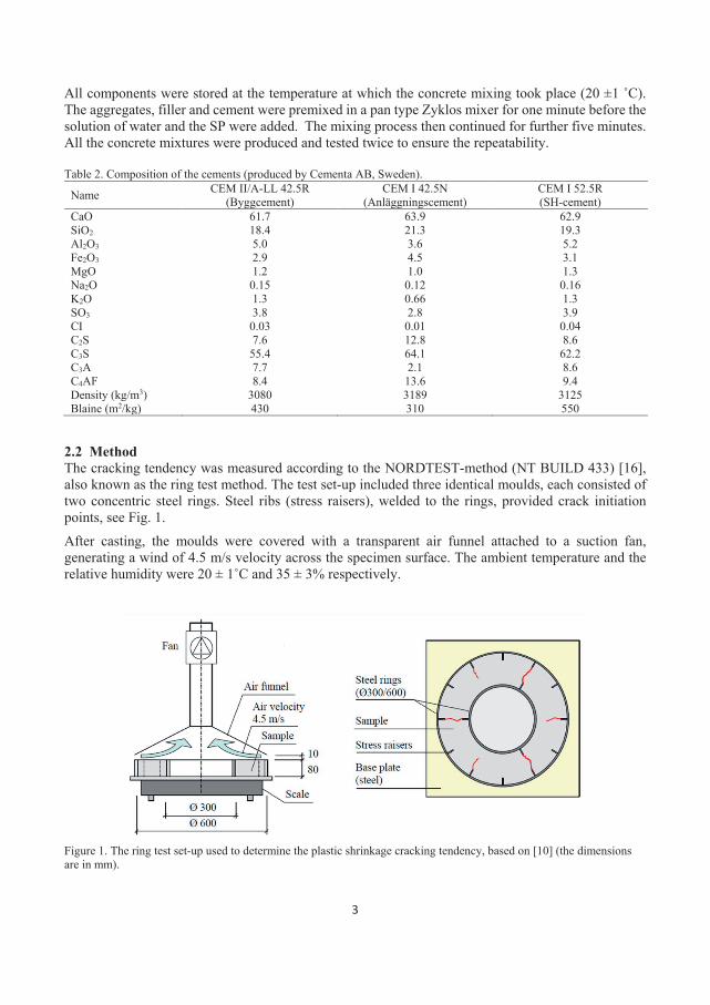
3
All components were stored at the temperature at which the concrete mixing took place (20 ±1 ˚C). The aggregates, filler and cement were premixed in a pan type Zyklos mixer for one minute before the solution of water and the SP were added. The mixing process then continued for further five minutes. All the concrete mixtures were produced and tested twice to ensure the repeatability. Table 2. Composition of the cements (produced by Cementa AB, Sweden).
Name CEM II/A-LL 42.5R (Byggcement)
CEM I 42.5N (Anläggningscement)
CEM I 52.5R (SH-cement)
CaO 61.7 63.9 62.9 SiO2 18.4 21.3 19.3 Al2O3 5.0 3.6 5.2 Fe2O3 2.9 4.5 3.1 MgO 1.2 1.0 1.3 Na2O 0.15 0.12 0.16 K2O 1.3 0.66 1.3 SO3 3.8 2.8 3.9 CI 0.03 0.01 0.04 C2S 7.6 12.8 8.6 C3S 55.4 64.1 62.2 C3A 7.7 2.1 8.6 C4AF 8.4 13.6 9.4 Density (kg/m3) 3080 3189 3125 Blaine (m2/kg) 430 310 550
2.2 Method The cracking tendency was measured according to the NORDTEST-method (NT BUILD 433) [16], also known as the ring test method. The test set-up included three identical moulds, each consisted of two concentric steel rings. Steel ribs (stress raisers), welded to the rings, provided crack initiation points, see Fig. 1. After casting, the moulds were covered with a transparent air funnel attached to a suction fan, generating a wind of 4.5 m/s velocity across the specimen surface. The ambient temperature and the relative humidity were 20 ± 1˚C and 35 ± 3% respectively.
Figure 1. The ring test set-up used to determine the plastic shrinkage cracking tendency, based on [10] (the dimensions are in mm).
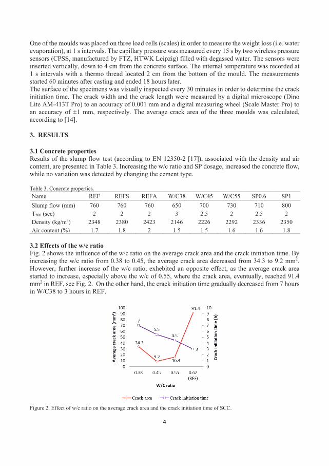
4
One of the moulds was placed on three load cells (scales) in order to measure the weight loss (i.e. water evaporation), at 1 s intervals. The capillary pressure was measured every 15 s by two wireless pressure sensors (CPSS, manufactured by FTZ, HTWK Leipzig) filled with degassed water. The sensors were inserted vertically, down to 4 cm from the concrete surface. The internal temperature was recorded at 1 s intervals with a thermo thread located 2 cm from the bottom of the mould. The measurements started 60 minutes after casting and ended 18 hours later. The surface of the specimens was visually inspected every 30 minutes in order to determine the crack initiation time. The crack width and the crack length were measured by a digital microscope (Dino Lite AM-413T Pro) to an accuracy of 0.001 mm and a digital measuring wheel (Scale Master Pro) to an accuracy of ±1 mm, respectively. The average crack area of the three moulds was calculated, according to [14]. 3. RESULTS 3.1 Concrete properties Results of the slump flow test (according to EN 12350-2 [17]), associated with the density and air content, are presented in Table 3. Increasing the w/c ratio and SP dosage, increased the concrete flow, while no variation was detected by changing the cement type. Table 3. Concrete properties. Name REF REFS REFA W/C38 W/C45 W/C55 SP0.6 SP1 Slump flow (mm) 760 760 760 650 700 730 710 800 T500 (sec) 2 2 2 3 2.5 2 2.5 2 Density (kg/m3) 2348 2380 2423 2146 2226 2292 2336 2350 Air content (%) 1.7 1.8 2 1.5 1.5 1.6 1.6 1.8
3.2 Effects of the w/c ratio Fig. 2 shows the influence of the w/c ratio on the average crack area and the crack initiation time. By increasing the w/c ratio from 0.38 to 0.45, the average crack area decreased from 34.3 to 9.2 mm2. However, further increase of the w/c ratio, exhebited an opposite effect, as the average crack area started to increase, especially above the w/c of 0.55, where the crack area, eventually, reached 91.4 mm2 in REF, see Fig. 2. On the other hand, the crack initiation time gradually decreased from 7 hours in W/C38 to 3 hours in REF.
Figure 2. Effect of w/c ratio on the average crack area and the crack initiation time of SCC.
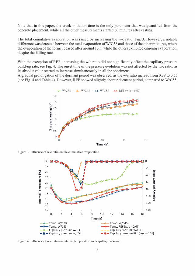
5
Note that in this paper, the crack initiation time is the only parameter that was quantified from the concrete placement, while all the other measurements started 60 minutes after casting. The total cumulative evaporation was raised by increasing the w/c ratio, Fig. 3. However, a notable difference was detected between the total evaporation of W/C38 and those of the other mixtures, where the evaporation of the former ceased after around 13 h, while the others exhibited ongoing evaporation, despite the falling rate. With the exception of REF, increasing the w/c ratio did not significantly affect the capillary pressure build-up rate, see Fig. 4. The onset time of the pressure evolution was not affected by the w/c ratio, as its absolut value started to increase simultaneously in all the specimens. A gradual prolongation of the dormant period was observed, as the w/c ratio incread from 0.38 to 0.55 (see Fig. 4 and Table 4). However, REF showed slightly shorter dormant period, compared to W/C55.
Figure 3. Influence of w/c ratio on the cumulative evaporation.
Figure 4. Influence of w/c ratio on internal temperature and capillary pressure.
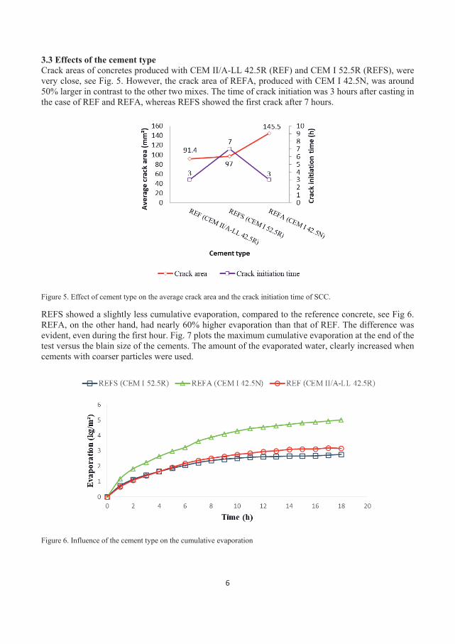
6
3.3 Effects of the cement type Crack areas of concretes produced with CEM II/A-LL 42.5R (REF) and CEM I 52.5R (REFS), were very close, see Fig. 5. However, the crack area of REFA, produced with CEM I 42.5N, was around 50% larger in contrast to the other two mixes. The time of crack initiation was 3 hours after casting in the case of REF and REFA, whereas REFS showed the first crack after 7 hours.
Figure 5. Effect of cement type on the average crack area and the crack initiation time of SCC.
REFS showed a slightly less cumulative evaporation, compared to the reference concrete, see Fig 6. REFA, on the other hand, had nearly 60% higher evaporation than that of REF. The difference was evident, even during the first hour. Fig. 7 plots the maximum cumulative evaporation at the end of the test versus the blain size of the cements. The amount of the evaporated water, clearly increased when cements with coarser particles were used.
Figure 6. Influence of the cement type on the cumulative evaporation
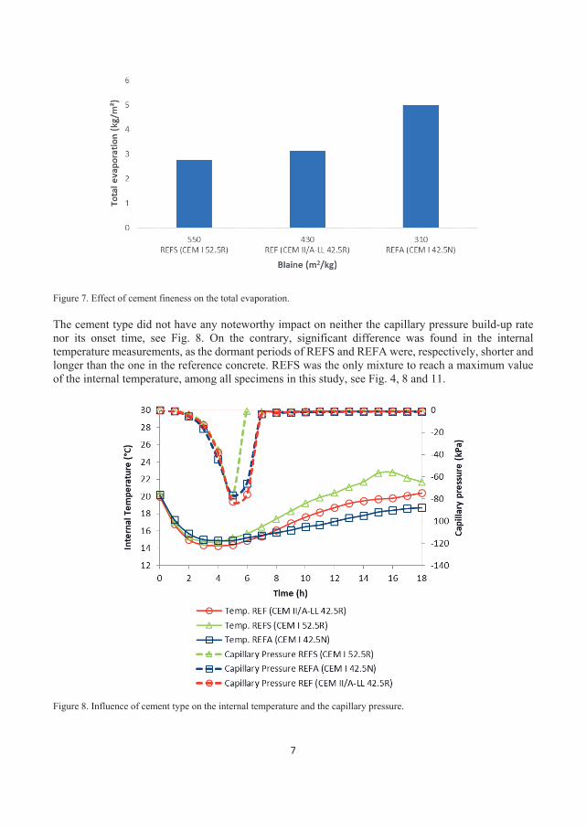
7
Figure 7. Effect of cement fineness on the total evaporation. The cement type did not have any noteworthy impact on neither the capillary pressure build-up rate nor its onset time, see Fig. 8. On the contrary, significant difference was found in the internal temperature measurements, as the dormant periods of REFS and REFA were, respectively, shorter and longer than the one in the reference concrete. REFS was the only mixture to reach a maximum value of the internal temperature, among all specimens in this study, see Fig. 4, 8 and 11.
Figure 8. Influence of cement type on the internal temperature and the capillary pressure.
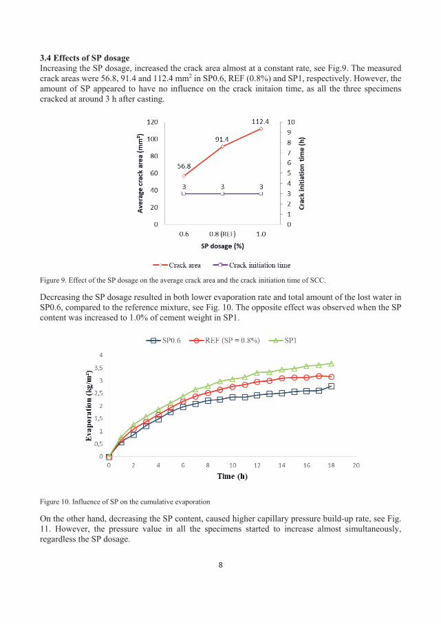
8
3.4 Effects of SP dosage Increasing the SP dosage, increased the crack area almost at a constant rate, see Fig.9. The measured crack areas were 56.8, 91.4 and 112.4 mm2 in SP0.6, REF (0.8%) and SP1, respectively. However, the amount of SP appeared to have no influence on the crack initaion time, as all the three specimens cracked at around 3 h after casting.
Figure 9. Effect of the SP dosage on the average crack area and the crack initiation time of SCC.
Decreasing the SP dosage resulted in both lower evaporation rate and total amount of the lost water in SP0.6, compared to the reference mixture, see Fig. 10. The opposite effect was observed when the SP content was increased to 1.0% of cement weight in SP1.
Figure 10. Influence of SP on the cumulative evaporation
On the other hand, decreasing the SP content, caused higher capillary pressure build-up rate, see Fig. 11. However, the pressure value in all the specimens started to increase almost simultaneously, regardless the SP dosage.
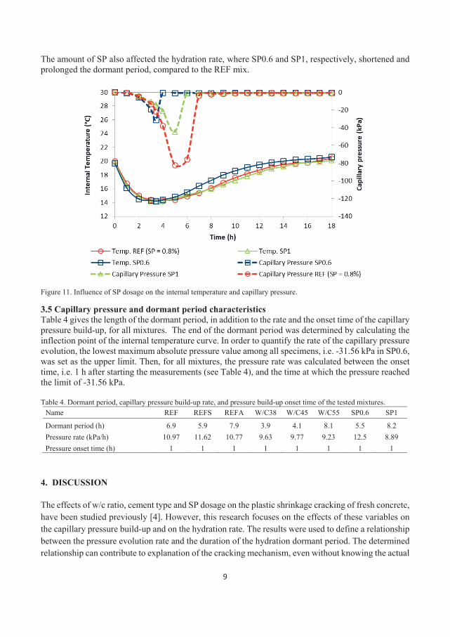
9
The amount of SP also affected the hydration rate, where SP0.6 and SP1, respectively, shortened and prolonged the dormant period, compared to the REF mix.
Figure 11. Influence of SP dosage on the internal temperature and capillary pressure.
3.5 Capillary pressure and dormant period characteristics Table 4 gives the length of the dormant period, in addition to the rate and the onset time of the capillary pressure build-up, for all mixtures. The end of the dormant period was determined by calculating the inflection point of the internal temperature curve. In order to quantify the rate of the capillary pressure evolution, the lowest maximum absolute pressure value among all specimens, i.e. -31.56 kPa in SP0.6, was set as the upper limit. Then, for all mixtures, the pressure rate was calculated between the onset time, i.e. 1 h after starting the measurements (see Table 4), and the time at which the pressure reached the limit of -31.56 kPa. Table 4. Dormant period, capillary pressure build-up rate, and pressure build-up onset time of the tested mixtures.
Name REF REFS REFA W/C38 W/C45 W/C55 SP0.6 SP1
Dormant period (h) 6.9 5.9 7.9 3.9 4.1 8.1 5.5 8.2 Pressure rate (kPa/h) 10.97 11.62 10.77 9.63 9.77 9.23 12.5 8.89 Pressure onset time (h) 1 1 1 1 1 1 1 1
4. DISCUSSION The effects of w/c ratio, cement type and SP dosage on the plastic shrinkage cracking of fresh concrete, have been studied previously [4]. However, this research focuses on the effects of these variables on the capillary pressure build-up and on the hydration rate. The results were used to define a relationship between the pressure evolution rate and the duration of the hydration dormant period. The determined relationship can contribute to explanation of the cracking mechanism, even without knowing the actual
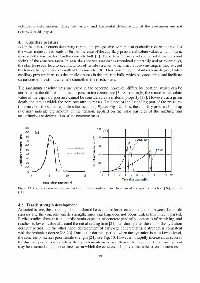
10
volumetric deformation. Thus, the vertical and horizontal deformations of the specimens are not reported in this paper. 4.1 Capillary pressure After the concrete enters the drying regime, the progressive evaporation gradually reduces the radii of the water menisci, and leads to further increase of the capillary pressure absolute value, which in turn, increases the tension level in the concrete bulk [3]. These tensile forces act on the solid particles and shrink of the concrete mass. In case the concrete member is restrained (internally and/or externally), the shrinkage can lead to accumulation of tensile stresses, which may cause cracking, if they exceed the low early age tensile strength of the concrete [18]. Thus, assuming constant restrain degree, higher capillary pressure increases the tensile stresses in the concrete bulk, which may accelerate and facilitate surpassing of the still low tensile strength in the plastic state.
The maximum absolute pressure value in the concrete, however, differs by location, which can be attributed to the difference in the air penetration occurrence [3]. Accordingly, the maximum absolute value of the capillary pressure cannot be considered as a material property [18]. However, at a given depth, the rate at which the pore pressure increases (i.e. slope of the ascending part of the pressure-time curve) is the same, regardless the location [19], see Fig. 12. Thus, the capillary pressure build-up rate may indicate the amount of the tension, applied on the solid particles of the mixture, and accordingly, the deformation of the concrete mass.
Figure 12: Capillary pressure measured at 4 cm from the surface in two locations of one specimen: a) from [20]; b) from [18]. 4.2 Tensile strength development As stated before, the cracking potential should be evaluated based on a comparison between the tensile stresses and the concrete tensile strength, since cracking does not occur, unless this limit is passed. Earlier studies show that the tensile strain capacity of concrete gradually decreases after mixing, and reaches its lowest value at around the initial setting time [21], i.e. shortly after the end of the hydration dormant period. On the other hand, development of early-age concrete tensile strength is consistent with the hydration degree [22, 23]. During the dormant period, when the hydration is at its lowest level, the concrete possesses poor tensile strength [24], see Fig. 13. However, it rapidly increases, as soon as the dormant period is over, where the hydration rate increases. Hence, the length of the dormant period may be assumed equal to the timespan at which the concrete is highly vulnerable to tensile stresses.
-100-90-80-70-60-50-40-30-20-10
00 5 10 15
Capi
llary
pre
ssur
e (k
Pa)
Time after casting (h)
Sensor 1
Sensor 2
(a) (b)
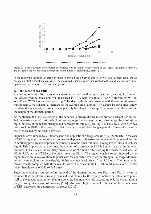
11
Figure 13: Tensile strength development of concretes with 194 kg/m3 water content (in the legend, the numbers after WC and SL denote the w/c ratio and the intended slump in inches, respectively), from [24]. In the following sections, an effort is made to explain the observed effects of w/c ratio, cement type, and SP dosage on plastic shrinkage cracking. The measured crack areas are then related to the capillary pressure build-up rate and the duration of the dormant period. 4.3 Influence of w/c ratio According to the results, the total evaporation increased with a higher w/c ratio, see Fig 3. However, the largest average crack area was measured in REF, with w/c ratio of 0.67, followed by W/C38, W/C55 and W/C45, respectively, see Fig. 2. Evidently, this is not consistent with the evaporation trend. Subsequently, the substantial increase of the average crack area in REF cannot be explained, solely, based on the evaporation. Instead, it can possibly be related to the capillary pressure build-up rate and the length of the dormant period. As mentioned, the tensile strength of the concrete is meagre during the hydration dormant period [22-24]. Increasing the w/c ratio, which in turn prolongs the dormant period, also delays the onset of the rapid increase of the tensile strength and decreases its rate [24], see Fig. 13. Thus, SCC with high w/c ratio, such as REF in this case, has lower tensile strength for a longer period of time which can be easily exceeded by the tensile stresses. Higher filler volume in SCC increases the risk of plastic shrinkage cracking [12]. Similarly, in the case of REF, a higher evaporation rate combined with presumably narrower pores rapidly increased the rate of capillary pressure development in comparison to the other mixtures, having lower fines content, see Fig. 4. This implies that at any time, the amount of shrinkage in REF is higher than that in the other mixtures. For instance, the capillary pressure value at 4 hours after starting the measurement was -38 kPa in REF, versus -27 kPa in the other three, see Fig. 4. The higher tensile stresses, induced by the higher faster pressure evolution, together with the concrete's lower tensile strength (i.e. longer dormant period), can explain the considerably higher average crack area of the REF mix. The crack width measurements complied with these results, where the cracks in REF (0.402 mm) were about 10 times wider than those in W/C45 (0.045 mm). Since the cracking occurred before the end of the dormant period, see Fig. 4 and Fig. 2, it can be assumed that the plastic shrinkage was induced mainly by the drying contraction. This corresponds well to the general assumption that in a concrete having a w/c ratio exceeding 0.5, the evaporation is the governing mechanism of cracking [5, 6]. Moreover, higher amount of limestone filler, as in case of REF, decreases the autogenous shrinkage [25-27].
00,10,20,30,40,50,60,7
0 2 4 6 8 10
Tens
ile st
reng
th (M
Pa)
Time after batching (h)
WC4SL1 WC5SL1 WC6SL1 WC7SL1
12
The lower evaporation measured in the W/C38 mix, presumably caused slower decrease of the radii of the menisci in the pores, which led to a somewhat lower capillary pressure build-up rate. However, the shorter dormant period was an indication of a faster hydration, which in turn reduced the intrinsic permeability of the mixture and blocked the pathways through which water was transported to the surface. Consequently, the menisci curvature decreased faster, and increased the capillary pressure build-up rate to be almost the same as W/C45 and W/C55. Moreover, taking the late crack initiation time of W/C38 into account, it seems that the shrinkage and cracking of the SCCs with low w/c ratios was mostly related to the autogenous deformation, which agrees well with the conclusions made by other researchers [5, 28, 29]. Note that in order to maintain the integrity of the mixture and avoiding any segregation, in addition to the w/c ratio, the mix design of the specimens tested here was modified by changing the cement, filler, aggregate, and SP content, see Table 1. This was made due to the broad range of the tested w/c ratios, i.e. 0.38 to 0.67. Thus, the reported results cannot be attributed to the effect of w/c ratio solely, and therefore, should be further investigated in future. 4.4 Influence of cement type Evaporation rate decreases by increasing the specific surface area of the cement particles [13]. A finer cement makes the pore structure denser, which in turn, reduces the permeability [30], and impedes the transportation of the capillary water to the surface. Cement composition, is another important factor that may explain the evaporation results. It has been observed that higher amount of C3A in cement, reduces the bleeding of the concrete [31], due to the accelerated hydration and the consequent reduction of the intrinsic permeability of the matrix [32]. Hence, the significant increase in the evaporation of REFA, compared to REF (Fig. 6), can be attributed to its presumably higher permeability due to the lower C3A content and coarser particles, see Table 2. Same argument can be used to explain the lower evaporation of REFS, as its finer particles and higher portion of C3A decrease the permeability. Finer pores, according to the Laplace equation [33, 34], may increase the absolute pore pressure value. However, in these particular tests, changing the cement type had a minor effect on the capillary pressure build-up rate, see Fig. 8 and Table 4. Hence, it seems that all mixtures should develop more or less equal ultimate shrinkage, assuming constant dormant period. However, this is not the case here, as REFS had a faster hydration and shorter dormant period, compared to REF, while REFA hydrated considerably slower. Higher specific area of the cement particles, i.e. finer cement, helps the dispersion of the particles which increases both the hydration rate and the hydration degree [13]. In addition, the presence of the higher amount of C3A, which liberates a significant amount of heat when it comes into contact with water, is another reason behind the faster hydration of REFS [31]. Thus, the difference in the length of the dormant period is the key parameter here, as it reveals the lower tensile strength of REFA. The cracking in REFA occurs before the end of the dormant period, compare Fig. 5 and Table 4. The relatively longer dormant period in REFA, means that the rate at which the concrete gains stiffness is lower. In other words, the specimen will be subjected to higher tension, induced by the capillary pressure, while at the same time the tensile strength develops at a lower rate. This indicates that, in REFA, the concrete cracks mainly due to plastic, rather than autogenous shrinkage. REFS cracked around the end of the dormant period. It has been observed that the accelerated hydration rate of finer cements leads to larger chemical shrinkage at early ages [34]. Moreover, the higher C3A content of CEM I 52.5R also facilitates a more rapid early age chemical shrinkage. Therefore, the cracks in the REFS seem to be partly autogenous, which complies well with the results of Esping and Löfgren [10].
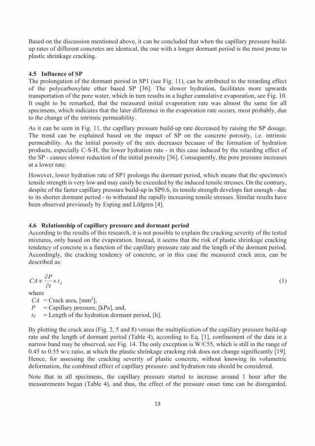
13
Based on the discussion mentioned above, it can be concluded that when the capillary pressure build-up rates of different concretes are identical, the one with a longer dormant period is the most prone to plastic shrinkage cracking.
4.5 Influence of SP The prolongation of the dormant period in SP1 (see Fig. 11), can be attributed to the retarding effect of the polycarboxylate ether based SP [36]. The slower hydration, facilitates more upwards transportation of the pore water, which in turn results in a higher cumulative evaporation, see Fig. 10. It ought to be remarked, that the measured initial evaporation rate was almost the same for all specimens, which indicates that the later difference in the evaporation rate occurs, most probably, due to the change of the intrinsic permeability. As it can be seen in Fig. 11, the capillary pressure build-up rate decreased by raising the SP dosage. The trend can be explained based on the impact of SP on the concrete porosity, i.e. intrinsic permeability. As the initial porosity of the mix decreases because of the formation of hydration products, especially C-S-H, the lower hydration rate - in this case induced by the retarding effect of the SP - causes slower reduction of the initial porosity [36]. Consequently, the pore pressure increases at a lower rate. However, lower hydration rate of SP1 prolongs the dormant period, which means that the specimen's tensile strength is very low and may easily be exceeded by the induced tensile stresses. On the contrary, despite of the faster capillary pressure build-up in SP0.6, its tensile strength develops fast enough - due to its shorter dormant period - to withstand the rapidly increasing tensile stresses. Similar results have been observed previously by Esping and Löfgren [4].
4.6 Relationship of capillary pressure and dormant period According to the results of this research, it is not possible to explain the cracking severity of the tested mixtures, only based on the evaporation. Instead, it seems that the risk of plastic shrinkage cracking tendency of concrete is a function of the capillary pressure rate and the length of the dormant period. Accordingly, the cracking tendency of concrete, or in this case the measured crack area, can be described as:
dttPCA ×∂∂
∝ (1)
where CA = Crack area, [mm2], P = Capillary pressure, [kPa], and, td = Length of the hydration dormant period, [h].
By plotting the crack area (Fig. 2, 5 and 8) versus the multiplication of the capillary pressure build-up rate and the length of dormant period (Table 4), according to Eq. [1], confinement of the data in a narrow band may be observed, see Fig. 14. The only exception is W/C55, which is still in the range of 0.45 to 0.55 w/c ratio, at which the plastic shrinkage cracking risk does not change significantly [19]. Hence, for assessing the cracking severity of plastic concrete, without knowing its volumetric deformation, the combined effect of capillary pressure- and hydration rate should be considered. Note that in all specimens, the capillary pressure started to increase around 1 hour after the measurements began (Table 4), and thus, the effect of the pressure onset time can be disregarded.
14
Otherwise, assuming constant capillary pressure build-up rate, the sooner the pressure starts to increase, the higher the cracking tendency, as the period between the tensile stress accumulation and the rapid tensile strength development - once the dormant period is ended – will be prolonged.
Fig 14. Crack area versus capillary pressure build-up rate multiplied by the length of the dormant period. 5. CONCLUSIONS Plastic shrinkage cracking is a complex interaction of several variables that may change under different circumstances and conditions at early ages. These variables may influence the evaporation, in addition to the capillary pressure- and hydration rate. According to the findings of this research, the severity of plastic shrinkage cracking in concrete is a function of the capillary pressure build-up rate and the length of the dormant period. Based on the results of this study, the following concluding remarks can be listed:
• Plastic shrinkage cracking tendency of concrete is directly proportional to the multiplication of the capillary pressure build-up rate and the length of the dormant period.
• SCC with high w/c ratio (higher than 0.55), cracks mainly due to plastic shrinkage, while autogenous shrinkage is the main cause of cracking in SCCs with low w/c ratio (lower than 0.45).
• Cracks in SCC, produced by using fine rapid hardening cements are caused by plastic and partly autogenous shrinkage. On the other hand, coarser normal hardening cements result in cracking, induced mainly by plastic shrinkage.
• Higher SP dosage decreases the capillary pressure build-up rate, delays the hydration and increases the evaporation. Concretes with higher SP dosage are more prone to plastic shrinkage cracking, despite the slower capillary pressure development.
• Assuming constant length of the hydration dormant period, the rate of capillary pressure evolution must be reduced by decreasing the evaporation. This can be done, among others, by fogging and/or covering the concrete surface.
15
6. FUTURE WORK The findings of this research gives a clearer picture about the role of capillary pressure and hydration rate in plastic shrinkage cracking. In future, the relationship discussed here can be used to develop new models to explain the phenomenon. ACKNOWLEDGMENT The authors would like to gratefully appreciate the financial support they received from the Development Fund of the Swedish Construction Industry, SBUF. Special thanks are also due to M.Sc. students and staff of the MCE and Thysell lab at Luleå University of Technology.
Funding: This study was funded by the Development Fund of the Swedish Construction Industry (case number 13401). REFERENCES
[1] W. Lerch, Plastic Shrinkage. ACI J. 53 (1957) 797-802.
[2] D. Ravina, R. Shalon, Plastic shrinkage cracking. ACI Mater J. 65 (1968) 282-291.
[3] V. Slowik, M. Schmidt, R. Fritzsch, Capillary pressure in fresh cement-based materials and identification of the air entry value. Cem Concr compos. 30(2008) 557-565.
[4] O. Esping, I. Löfgren, Cracking due to plastic and autogenous shrinkage-investigation of early age deformation of self-compacting concrete-experimental study, Technical report, Chalmers University of Technology, Sweden, 2005.
[5] P. Turcry, A. Loukili, Evaluation of plastic shrinkage cracking of self-consolidating concrete. ACI. Mat. J. 10 (2006) 272-279.
[6] O. Esping, Early age properties of self-compacting concrete- Effects of fine aggregate and limestone filler, doctoral thesis, Chalmers University of Technology, Göteborg, Sweden, 2007.
[7] P. Lura, B. Pease, G.B. Mazzotta, F. Rajabipour, J. Weiss, Influence of shrinkage-reducing admixtures on development of plastic shrinkage cracks. ACI Materials Journal 104(2007) 187.
[8] B. Persson, Plastic shrinkage of self-compacting concrete. In: Jensen, O.M., Geiker, M., Stang, H. (eds.) Proceedings of the Knud Hojgaard Conference, Lyngby, Report R-155 DTU, (2005) 43-57.
[9] H.E. Gram, P. Pentti, Properties of SCC: Especially early age and long term shrinkage and salt frost resistance. In: Skarendahl, Å., Petersson, Ö. (eds.) Proceedings of the 1st In-ternational RILEM Symposium on Self-compacting Concrete, Stockholm, RILEM Publications S.A.R.L., Bagneux, (1999) 211-225.
[10] I. Löfgren, O. Esping, O. Jensen, P. Lura, K. Kovler, Early age cracking of self-compacting concrete. International RILEM Conference on Volume Changes of Hardening Concrete: Testing and Mitigation, Lyngby, (2006) 251-260.
[11] A. Leemann, P. Lura, Creep and Shrinkage of SCC. In Mechanical Properties of Self-Compacting Concrete, edited by K. H. Khayat and G. DeSchutter, New York, 2014, pp. 73– 94
[12] T.A Hammer, Cracking susceptibility due to volume changes of self-compacting concrete (SCC). In: Wallevik, O., Nielsson, I. (eds.) Proceedings of the 3rd International RILEM Symposium on SCC, Reykjavik,. RILEM Publications S.A.R.L., Bagneux, (2003) 553-557
[13] K. Yang, M. Zhong, B. Magee, C. Yang, C. Wang, X. Zhu, Z. Zhang, Investigation of effects of Portland cement fineness and alkali content on concrete plastic shrinkage cracking, Constr. Build. Mater 144 (2017) 279-290.
[14] O. Esping, I. Löfgren, J. Marchand, B. Bissonnette, R. Gagné, M. Jolin, Investigation of early age deformation in self-compacting concrete. Proceedings of the 2nd International Symposium on Advances in Concrete Science, Quebec, (2006).
16
[15] EN 197-1, Cement: Composition, Specifications and Conformity Criteria for Common Cements, Br. Stand. Inst. London. 2000.
[16] R. Johansen, P. Dahl, Control of plastic shrinkage of cement. Proceedings of the 18th Conference on Our World in Concrete and Structures, Singapore. (1993).
[17] EN 12350e12352, Testing Fresh Concrete: Slump Test, Br. Stand. Inst, London. 2000. [18] V. Slowik, M. Schmidt, Early age cracking and capillary pressure controlled concrete curing. Adv Cem-Based Mater
(2009) 229-234.
[19] F. Sayahi, Plastic Shrinkage Cracking in Concrete, Licentiate thesis, Luleå University of Technology, 2016. [20] Sayahi, F., Emborg, M., Hedlund, H. and Löfgren, L., 2016. Plastic Shrinkage Cracking in Self-Compacting
Concrete: A Parametric Study, International RILEM conference on Materials, Systems and Structures in Civil Engineering, MSSCE 2016 2016, pp. 609-619
[21] Boshoff WP, Combrinck R. "Modelling the severity of plastic shrinkage cracking in concrete". Cement and Concrete Research. Vol.48, 2013 JUN, pp.34-39.
[22] V.T.N Dao, P.F. Dux, P.H. Horris, Tensile properties of early-age concrete. ACI Mater J. 106 (2009) 483–92.
[23] T.A. Hammer, K. T. Fosså, Cracking tendency of HSE: Tensile strength and self-generated stress in the period of setting and early hardening, Materi Struct. 40 (2007) 319-324.
[24] J. Abel, K. Hover, Effect of water/cement ration the early age tensile strength of concrete, Transportation Research Record: Transport Research Board. 1610 (1998) 33-38.
[25] A.M. Poppe, G. De Schutter, Creep and shrinkage of self-compacting concrete. In: Yu, Z, Shi C, Khayat KH, Xie Y (eds) Proceedings of the 1st International RILEM Symposium on SCC. RILEM Publications S.A.R.L, Bagneux (2005) 329-336
[26] E. Rozière, S. Granger, P. Turcry, A. Loukili, Influence of paste volume on shrinkage cracking and fracture properties of self-compacting concrete. Cem. Conc. Comp. 29 (2007), 626-636.
[27] G. Pons, E. Proust, S. Assié, Creep and shrinkage of self-compacting concrete: a differ-ent behaviour compared with vibrated concrete. In: Wallevik, Ó., Nielsson, I. (eds) Pro-ceedings of the 3rd International RILEM Symposium on SCC, Reykjavik. RILEM Publications S.A.R.L., Bagneux (2003) 645-654
[28] Darquennes, M.I.A Khokhar, E. Rozière, A. Loukili, F. Grondin, S. Staquet, Early age deformations of concrete with high content of mineral additions. Constr Build Mater 25 (2011)1836–47.
[29] J. Mora-Ruacho, R. Gettu, A. Aguado, Influence of shrinkage-reducing admixtures on the reduction of plastic shrinkage cracking in concrete. Cem Concr Res. 39 (2009) 141–146
[30] S. Ghourchian, M. Wyrzykowski, L. Baquerizo, P. Lura, Susceptibility of Portland cement and blended cement concretes to plastic shrinkage cracking. Cem Concr Com. 85 (2018) 44-55.
[31] A.M Neville, J.J. Brooks. Concrete Technology. Longman, London. 1990. [32] S. Ghourchian, M. Wyrzykowski, L. Baquerizo, P. Lura, A poromechanics model for plastic shrinkage of fresh
cementitious materials. Cement and Concrete Research. 31 (2018) 120-32. [33] F.H. Wittmann, On the action of capillary pressure on fresh concrete, Cem Concr Res. 6 (1976) 49-56. [34] F. Sayahi, M. Emborg, H. Hedlund, Plastic shrinkage cracking in concrete: State of the art. J Nord Concr Res,
51(2014) 95-16.
[35] L.M. Dellinghausen, A.L.G. Gastaldini, F.J. Vanzin, K.K. Veiga, Total shrinkage, oxygen permeability, and chloride ion penetration in concrete made with white Portland cement and blast-furnace slag, Constr Build Mater. 37 (2012) 652–659.
[36] Gu, Ping, Xie. Ping, J.J. Beaudoin, C. Jolicoeur, Investigation of the Retarding Effect of Superplasticizers on Cement Hydration by Impedence Spectroscopy and Other Methods. Cem Concr Res. 24 (1994) 433-442.

PAPER V: The Severity of Plastic Shrinkage Cracking in Concrete: A New Model Sayahi, F., Emborg, M., Hedlund, H., and Cwirzen, A., Stelmarczyk, M., Submitted.

The Severity of Plastic Shrinkage Cracking in Concrete: A New Model Faez Sayahia, Mats Emborga,b, Hans Hedlunda,c, Andrzej Cwirzena, Marcin Stelmarczyka,d
a Department of Civil, Environmental and Natural Resources Engineering, Luleå University of Technology, 971 87 Luleå, Sweden
b Betongindustri AB, 100 74 Stockholm, Sweden. c Skanska Sverige AB, Gothenburg, Sweden d Green Dragon Magic, Stockholm, Sweden Corresponding author: Faez Sayahia, e-mail: [email protected], Tel: +46 76 409 1933. ABSTRACT
Plastic shrinkage cracking in concrete is mainly a physical process in which chemical reactions between cement and water do not play a decisive role. It is commonly believed that rapid and excessive moisture loss in form of evaporation is the primary cause of the phenomenon. This paper presents a new model to estimate the severity of plastic shrinkage cracking in concrete based on the initial setting time and the amount of the evaporated water from within the concrete. A number of experiments were performed under controlled ambient conditions, during which water-cement ratio, cement type and dosage of superplasticizer were altered. Results reported by other researchers were utilized, to check the validity of the proposed model. According to the outcomes, the model could predict the cracking severity of the tested concretes with relative precision.
Keywords: plastic shrinkage, cracking, initial setting, evaporation, bleeding, modelling.
1. INTRODUCTION Plastic shrinkage cracking mainly occurs in fresh concrete elements with a high surface to volume ratio, e.g. slabs. The principal driving force behind the phenomenon is rapid and excessive moisture loss due to evaporation, which leads to a negative capillary pressure build-up in the pore system. Consequently, the solid particles are subjected to tensile stresses, while the concrete is still in the plastic state and have not gained a sufficient tensile strength [1, 2].
Once the concrete is cast, its solid particles settle due to gravity, causing an upward water-flow from inside of the concrete and through its pore system to the surface, i.e. bleeding regime [3]. When the amount of the evaporated water exceeds the amount of the water accumulated at the concrete surface, i.e. bleed water, concrete enters the drying regime during which water menisci are formed inside the pores causing a build-up of a negative capillary pressure [4].
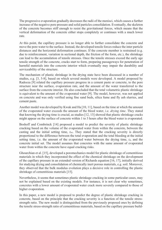
The progressive evaporation gradually decreases the radii of the menisci, which causes a further increase of the negative pore pressure and solid particles consolidation. Eventually, the skeleton of the concrete becomes stiff enough to resist the gravitational forces, which means that the vertical deformation of the concrete either stops completely or continues with a much lower rate.
At this point, the capillary pressure is no longer able to further consolidate the concrete and move the pore water to the surface. Instead, the developed tensile forces reduce the inter particle distances and the horizontal deformation continues. If the concrete member is restrained (e.g. due to reinforcement, variation in sectional depth, the friction of the form, etc.), the shrinkage can lead to the accumulation of tensile stresses. Once the tensile stresses exceed the early age tensile strength of the concrete, cracks start to form, preparing passageways for penetration of harmful materials into the concrete interior which eventually may impair the durability and serviceability of the structure. The mechanism of plastic shrinkage in the drying state have been discussed in a number of studies, e.g. [3, 5-8], based on which several models were developed. A model proposed by Radocea [9] related the capillary pressure progress in a cement paste or concrete, to the pore structure near the surface, evaporation rate, and the amount of the water transferred to the surface from the concrete interior. He also concluded that the total volumetric plastic shrinkage is equivalent to the amount of the evaporated water [9]. The model, however, was not applied on concrete and was only verified using fine sand beds, silica fume and fly ash slurries, and cement paste.
Another model was developed by Kwak and Ha [10, 11], based on the time at which the amount of the evaporated water exceeds the amount of the bleed water, i.e. drying time. They stated that knowing the drying time is crucial, as studies [12, 13] showed that plastic shrinkage cracks might appear on the surface of concrete within 1 to 3 hours after the bleed water is evaporated.
Boshoff and Combrinck [14] proposed a model to predict the severity of plastic shrinkage cracking based on the volume of the evaporated water from within the concrete, between the casting and the initial setting time, tini. They stated that the cracking severity is directly proportional to the difference between the total evaporation and the total bleeding at the initial setting time, i.e. the amount of the evaporated water between the drying time, td, and the concrete initial set. The model assumes that concretes with the same amount of evaporated water from within the concrete have equal cracking risks.
Ghourchian et al. [15], developed a poromechanics model for plastic shrinkage of cementitious materials in which they incorporated the effect of the chemical shrinkage on the development of the capillary pressure in an extended version of Richards equation [16, 17], initially derived for studying drying and consolidation of chemically inert porous materials, e.g. soil. Moreover, they observed that the bulk modulus evolution plays a decisive role in controlling the plastic shrinkage of cementitious materials [15].
Nevertheless, it seems that sometimes plastic shrinkage cracking in some particular cases, may not be explained based on the existing models. For instance, it is not clear why sometimes, concretes with a lower amount of evaporated water crack more severely compared to those of higher evaporation.
In this paper, a new model is proposed to predict the degree of plastic shrinkage cracking in concrete, based on the principle that the cracking severity is a function of the tensile stress-strength ratio. The new model is distinguished from the previously proposed ones by defining the tensile stress-strength ratio of cementitious materials, based on the capillary pressure build-
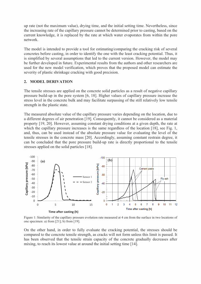
up rate (not the maximum value), drying time, and the initial setting time. Nevertheless, since the increasing rate of the capillary pressure cannot be determined prior to casting, based on the current knowledge, it is replaced by the rate at which water evaporates from within the pore network. The model is intended to provide a tool for estimating/comparing the cracking risk of several concretes before casting, in order to identify the one with the least cracking potential. Thus, it is simplified by several assumptions that led to the current version. However, the model may be further developed in future. Experimental results from the authors and other researchers are used for the new model verification, which proves that the proposed model can estimate the severity of plastic shrinkage cracking with good precision. 2. MODEL DERIVATION The tensile stresses are applied on the concrete solid particles as a result of negative capillary pressure build-up in the pore system [6, 18]. Higher values of capillary pressure increase the stress level in the concrete bulk and may facilitate surpassing of the still relatively low tensile strength in the plastic state. The measured absolute value of the capillary pressure varies depending on the location, due to a different degrees of air penetration [19]. Consequently, it cannot be considered as a material property [19, 20]. However, assuming constant drying conditions at a given depth, the rate at which the capillary pressure increases is the same regardless of the location [18], see Fig. 1, and, thus, can be used instead of the absolute pressure value for evaluating the level of the tensile stresses in the concrete mass [20]. Accordingly, assuming constant restrain degree, it can be concluded that the pore pressure build-up rate is directly proportional to the tensile stresses applied on the solid particles [18].
Figure 1: Similarity of the capillary pressure evolution rate measured at 4 cm from the surface in two locations of one specimen: a) from [21]; b) from [19]. On the other hand, in order to fully evaluate the cracking potential, the stresses should be compared to the concrete tensile strength, as cracks will not form unless this limit is passed. It has been observed that the tensile strain capacity of the concrete gradually decreases after mixing, to reach its lowest value at around the initial setting time [14].
-100-90-80-70-60-50-40-30-20-10
00 5 10 15
Capi
llary
pre
ssur
e (k
Pa)
Time after casting (h)
Sensor 1
Sensor 2
(a) (b)
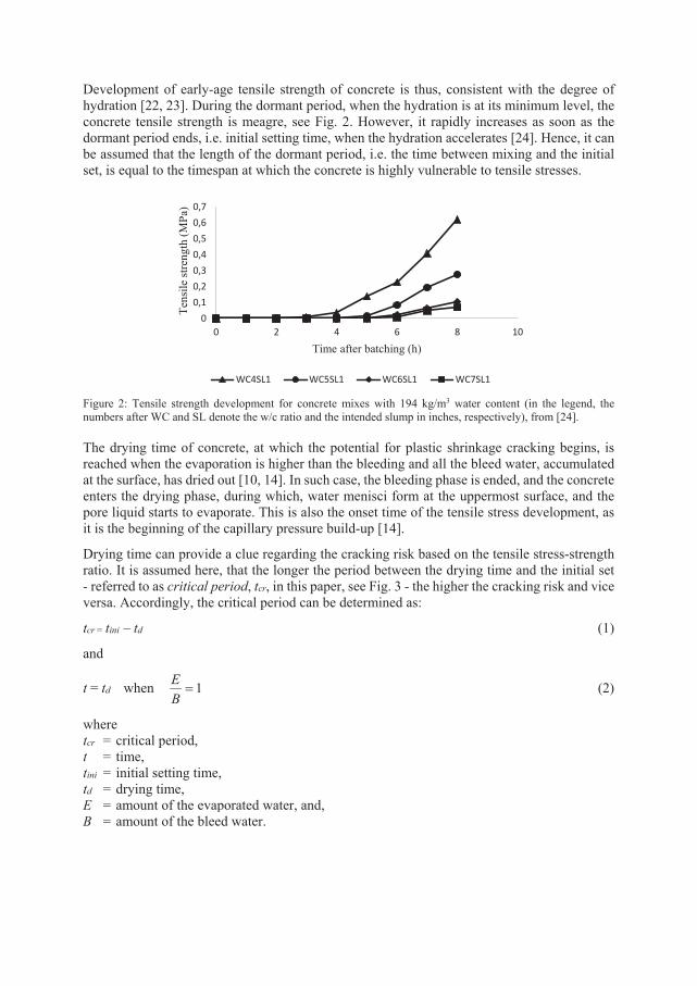
Development of early-age tensile strength of concrete is thus, consistent with the degree of hydration [22, 23]. During the dormant period, when the hydration is at its minimum level, the concrete tensile strength is meagre, see Fig. 2. However, it rapidly increases as soon as the dormant period ends, i.e. initial setting time, when the hydration accelerates [24]. Hence, it can be assumed that the length of the dormant period, i.e. the time between mixing and the initial set, is equal to the timespan at which the concrete is highly vulnerable to tensile stresses.
Figure 2: Tensile strength development for concrete mixes with 194 kg/m3 water content (in the legend, the numbers after WC and SL denote the w/c ratio and the intended slump in inches, respectively), from [24]. The drying time of concrete, at which the potential for plastic shrinkage cracking begins, is reached when the evaporation is higher than the bleeding and all the bleed water, accumulated at the surface, has dried out [10, 14]. In such case, the bleeding phase is ended, and the concrete enters the drying phase, during which, water menisci form at the uppermost surface, and the pore liquid starts to evaporate. This is also the onset time of the tensile stress development, as it is the beginning of the capillary pressure build-up [14].
Drying time can provide a clue regarding the cracking risk based on the tensile stress-strength ratio. It is assumed here, that the longer the period between the drying time and the initial set - referred to as critical period, tcr, in this paper, see Fig. 3 - the higher the cracking risk and vice versa. Accordingly, the critical period can be determined as:
tcr = tini – td (1)
and
t = td when 1=BE (2)
where tcr = critical period, t = time, tini = initial setting time, td = drying time, E = amount of the evaporated water, and, B = amount of the bleed water.
00,10,20,30,40,50,60,7
0 2 4 6 8 10
Tens
ile st
reng
th (M
Pa)
Time after batching (h)
WC4SL1 WC5SL1 WC6SL1 WC7SL1
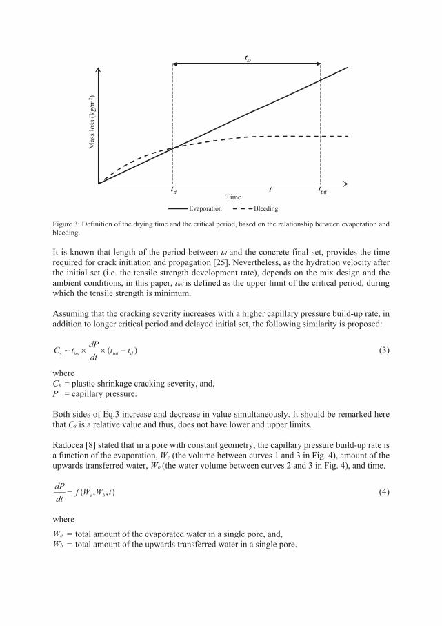
Figure 3: Definition of the drying time and the critical period, based on the relationship between evaporation and bleeding.
It is known that length of the period between td and the concrete final set, provides the time required for crack initiation and propagation [25]. Nevertheless, as the hydration velocity after the initial set (i.e. the tensile strength development rate), depends on the mix design and the ambient conditions, in this paper, tini is defined as the upper limit of the critical period, during which the tensile strength is minimum. Assuming that the cracking severity increases with a higher capillary pressure build-up rate, in addition to longer critical period and delayed initial set, the following similarity is proposed:
)(~ diniinis ttdtdPtC −×× (3)
where Cs = plastic shrinkage cracking severity, and, P = capillary pressure. Both sides of Eq.3 increase and decrease in value simultaneously. It should be remarked here that Cs is a relative value and thus, does not have lower and upper limits. Radocea [8] stated that in a pore with constant geometry, the capillary pressure build-up rate is a function of the evaporation, We (the volume between curves 1 and 3 in Fig. 4), amount of the upwards transferred water, Wb (the water volume between curves 2 and 3 in Fig. 4), and time.
),,( tWWfdtdP
be= (4)
where We = total amount of the evaporated water in a single pore, and, Wb = total amount of the upwards transferred water in a single pore.
Mas
s los
s (kg
/m2 )
TimeEvaporation Bleeding
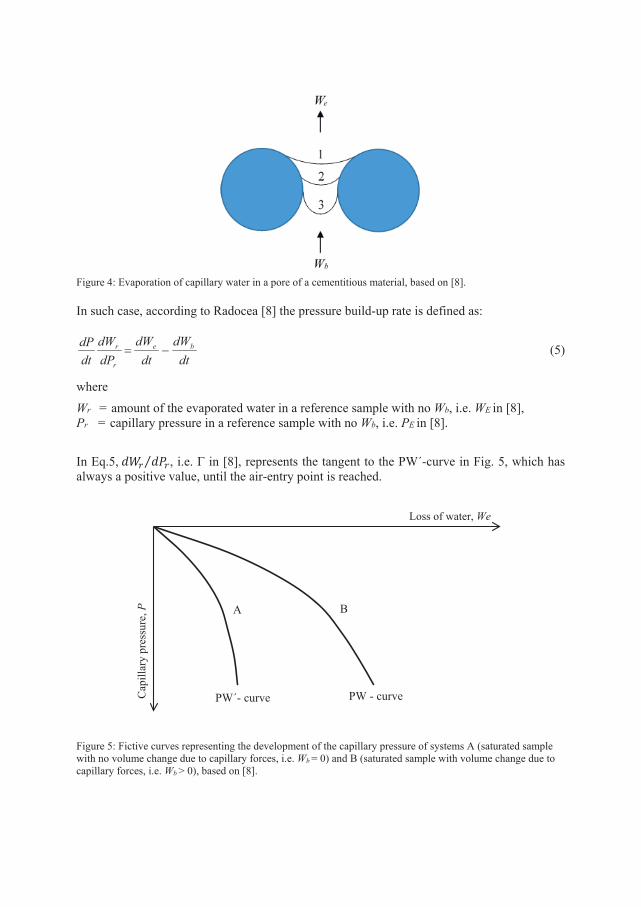
Figure 4: Evaporation of capillary water in a pore of a cementitious material, based on [8].
In such case, according to Radocea [8] the pressure build-up rate is defined as:
dtdW
dtdW
dPdW
dtdP be
r
r −= (5)
where Wr = amount of the evaporated water in a reference sample with no Wb, i.e. WE in [8], Pr = capillary pressure in a reference sample with no Wb, i.e. PE in [8].
In Eq.5, 𝑑𝑑𝑑𝑑𝑟𝑟 𝑑𝑑𝑑𝑑𝑟𝑟⁄ , i.e. Γ in [8], represents the tangent to the PW΄-curve in Fig. 5, which has always a positive value, until the air-entry point is reached.
Figure 5: Fictive curves representing the development of the capillary pressure of systems A (saturated sample with no volume change due to capillary forces, i.e. Wb = 0) and B (saturated sample with volume change due to capillary forces, i.e. Wb > 0), based on [8].
Cap
illar
y pr
essu
re, P
Loss of water, We
PW΄- curve PW - curve
A B
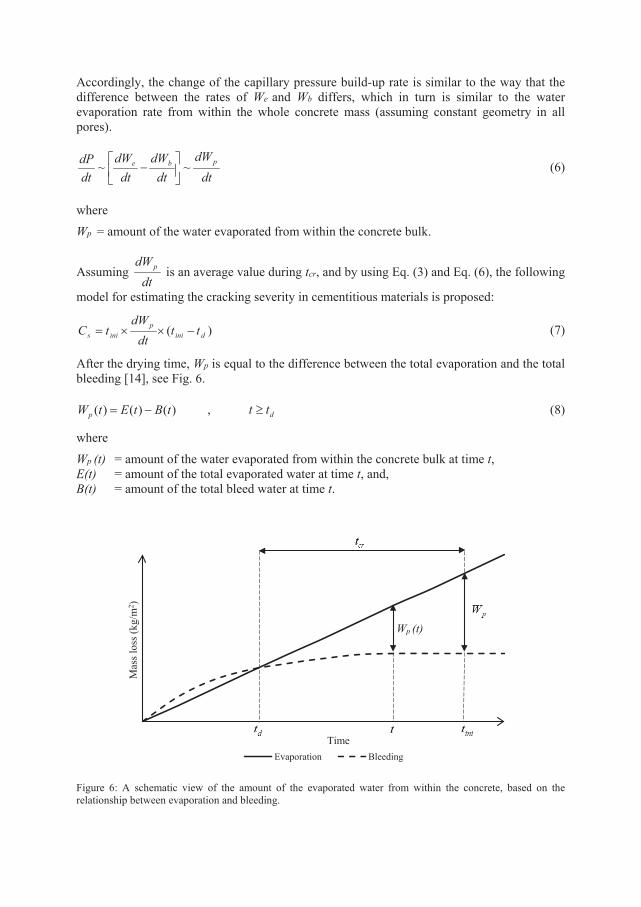
Accordingly, the change of the capillary pressure build-up rate is similar to the way that the difference between the rates of We and Wb differs, which in turn is similar to the water evaporation rate from within the whole concrete mass (assuming constant geometry in all pores).
dtdW
dtdW
dtdW
dtdP pbe ~~
− (6)
where Wp = amount of the water evaporated from within the concrete bulk.
Assuming dt
dWp is an average value during tcr, and by using Eq. (3) and Eq. (6), the following
model for estimating the cracking severity in cementitious materials is proposed:
)( dinip
inis ttdt
dWtC −××= (7)
After the drying time, Wp is equal to the difference between the total evaporation and the total bleeding [14], see Fig. 6.
)()()( tBtEtWp −= , dtt ≥ (8)
where Wp (t) = amount of the water evaporated from within the concrete bulk at time t, E(t) = amount of the total evaporated water at time t, and, B(t) = amount of the total bleed water at time t.
Figure 6: A schematic view of the amount of the evaporated water from within the concrete, based on the relationship between evaporation and bleeding.
Mas
s los
s (kg
/m2 )
TimeEvaporation Bleeding
Wp (t)
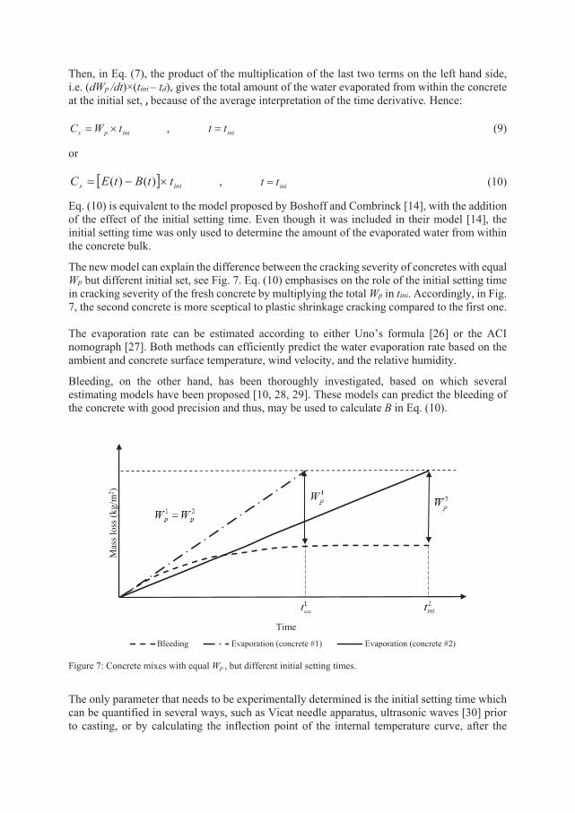
Then, in Eq. (7), the product of the multiplication of the last two terms on the left hand side, i.e. (dWp /dt)×(tini – td), gives the total amount of the water evaporated from within the concrete at the initial set, , because of the average interpretation of the time derivative. Hence:
inips tWC ×= , initt = (9)
or
[ ] inis ttBtEC ×−= )()( , initt = (10)
Eq. (10) is equivalent to the model proposed by Boshoff and Combrinck [14], with the addition of the effect of the initial setting time. Even though it was included in their model [14], the initial setting time was only used to determine the amount of the evaporated water from within the concrete bulk.
The new model can explain the difference between the cracking severity of concretes with equal Wp but different initial set, see Fig. 7. Eq. (10) emphasises on the role of the initial setting time in cracking severity of the fresh concrete by multiplying the total Wp in tini. Accordingly, in Fig. 7, the second concrete is more sceptical to plastic shrinkage cracking compared to the first one. The evaporation rate can be estimated according to either Uno’s formula [26] or the ACI nomograph [27]. Both methods can efficiently predict the water evaporation rate based on the ambient and concrete surface temperature, wind velocity, and the relative humidity.
Bleeding, on the other hand, has been thoroughly investigated, based on which several estimating models have been proposed [10, 28, 29]. These models can predict the bleeding of the concrete with good precision and thus, may be used to calculate B in Eq. (10).
Figure 7: Concrete mixes with equal Wp , but different initial setting times.
The only parameter that needs to be experimentally determined is the initial setting time which can be quantified in several ways, such as Vicat needle apparatus, ultrasonic waves [30] prior to casting, or by calculating the inflection point of the internal temperature curve, after the
Mas
s los
s (kg
/m2 )
Time
Bleeding Evaporation (concrete #1) Evaporation (concrete #2)
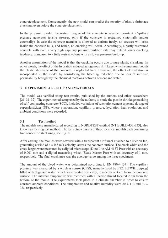
concrete placement. Consequently, the new model can predict the severity of plastic shrinkage cracking, even before the concrete placement. In the proposed model, the restrain degree of the concrete is assumed constant. Capillary pressure generates tensile stresses, only if the concrete is restrained (internally and/or externally). In case the concrete member is allowed to deform freely, no stresses will arise inside the concrete bulk, and hence, no cracking will occur. Accordingly, a partly restrained concrete with even a very high capillary pressure build-up rate may exhibit lower cracking tendency, compared to a fully restrained one with a slower pressure build-up. Another assumption of the model is that the cracking occurs due to pure plastic shrinkage. In other words, the effect of the hydration induced autogenous shrinkage, which sometimes boosts the plastic shrinkage of the concrete is neglected here. However, the effect of hydration is incorporated in the model by considering the bleeding reduction due to loss of intrinsic permeability brought by the chemical reactions between cement and water.
3. EXPERIMENTAL SETUP AND MATERIALS The model was verified using test results, published by the authors and other researchers [21, 31, 32]. The experimental setup used by the authors, to study the plastic shrinkage cracking of self-compacting concrete (SCC), included variations of w/c ratio, cement type and dosage of superplasticizer (SP), where evaporation, capillary pressure, hydration heat evolution, and ambient conditions were recorded.
3.1 Test method The moulds were manufactured according to NORDTEST-method (NT BUILD 433) [33], also known as the ring test method. The test setup consists of three identical moulds each containing two concentric steel rings, see Fig. 8. After casting, the moulds were covered with a transparent air funnel attached to a suction fan, generating a wind of 4 ± 0.5 m/s velocity, across the concrete surface. The crack width and the crack length were measured by a digital microscope (Dino Lite AM-413T Pro) with an accuracy of 0.001 mm and a digital measuring wheel (Scale Master Pro) with an accuracy of 1 mm, respectively. The final crack area was the average value among the three specimens. The amount of the bleed water was determined according to EN 480-4 [34]. The capillary pressure was measured by a wireless sensor (CPSS, manufactured by FTZ, HTWK Leipzig) filled with degassed water, which was inserted vertically, to a depth of 4 cm from the concrete surface. The internal temperature was recorded with a thermo thread located 2 cm from the bottom of the mould. The experiments took place in a climate chamber in order to ensure constant ambient conditions. The temperature and relative humidity were 20 ± 1˚C and 30 ± 3%, respectively.
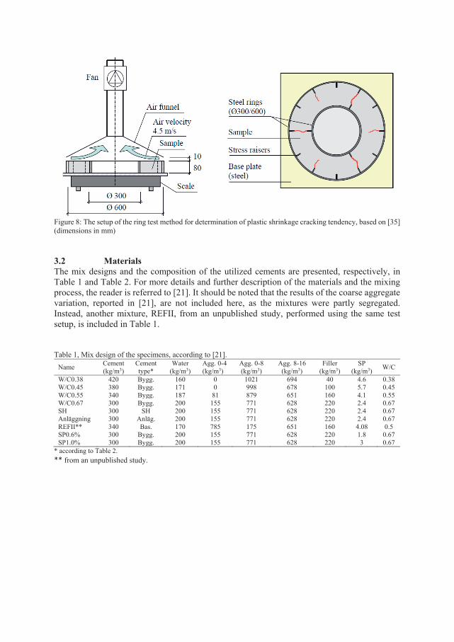
Figure 8: The setup of the ring test method for determination of plastic shrinkage cracking tendency, based on [35] (dimensions in mm) 3.2 Materials The mix designs and the composition of the utilized cements are presented, respectively, in Table 1 and Table 2. For more details and further description of the materials and the mixing process, the reader is referred to [21]. It should be noted that the results of the coarse aggregate variation, reported in [21], are not included here, as the mixtures were partly segregated. Instead, another mixture, REFII, from an unpublished study, performed using the same test setup, is included in Table 1. Table 1, Mix design of the specimens, according to [21].
Name Cement (kg/m3)
Cement type*
Water (kg/m3)
Agg. 0-4 (kg/m3)
Agg. 0-8 (kg/m3)
Agg. 8-16 (kg/m3)
Filler (kg/m3)
SP (kg/m3) W/C
W/C0.38 420 Bygg. 160 0 1021 694 40 4.6 0.38 W/C0.45 380 Bygg. 171 0 998 678 100 5.7 0.45 W/C0.55 340 Bygg. 187 81 879 651 160 4.1 0.55 W/C0.67 300 Bygg. 200 155 771 628 220 2.4 0.67 SH 300 SH 200 155 771 628 220 2.4 0.67 Anläggning 300 Anläg. 200 155 771 628 220 2.4 0.67 REFII** 340 Bas. 170 785 175 651 160 4.08 0.5 SP0.6% 300 Bygg. 200 155 771 628 220 1.8 0.67 SP1.0% 300 Bygg. 200 155 771 628 220 3 0.67
* according to Table 2. ** from an unpublished study.
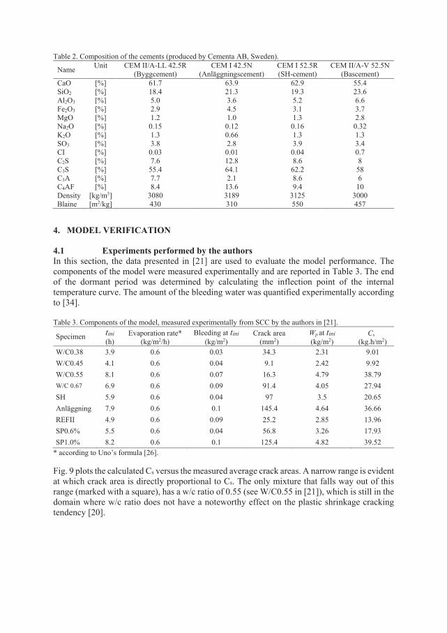
Table 2. Composition of the cements (produced by Cementa AB, Sweden). Name Unit CEM II/A-LL 42.5R
(Byggcement) CEM I 42.5N
(Anläggningscement) CEM I 52.5R (SH-cement)
CEM II/A-V 52.5N (Bascement)
CaO [%] 61.7 63.9 62.9 55.4 SiO2 [%] 18.4 21.3 19.3 23.6 Al2O3 [%] 5.0 3.6 5.2 6.6 Fe2O3
[%] 2.9 4.5 3.1 3.7 MgO [%] 1.2 1.0 1.3 2.8 Na2O [%] 0.15 0.12 0.16 0.32 K2O [%] 1.3 0.66 1.3 1.3 SO3 [%] 3.8 2.8 3.9 3.4 CI [%] 0.03 0.01 0.04 0.7 C2S [%] 7.6 12.8 8.6 8 C3S [%] 55.4 64.1 62.2 58 C3A [%] 7.7 2.1 8.6 6 C4AF [%] 8.4 13.6 9.4 10 Density [kg/m3] 3080 3189 3125 3000 Blaine [m2/kg] 430 310 550 457
4. MODEL VERIFICATION
4.1 Experiments performed by the authors In this section, the data presented in [21] are used to evaluate the model performance. The components of the model were measured experimentally and are reported in Table 3. The end of the dormant period was determined by calculating the inflection point of the internal temperature curve. The amount of the bleeding water was quantified experimentally according to [34]. Table 3. Components of the model, measured experimentally from SCC by the authors in [21].
Specimen tini (h)
Evaporation rate* (kg/m2/h)
Bleeding at tini (kg/m2)
Crack area (mm2)
Wp at tini (kg/m2)
Cs (kg.h/m2)
W/C0.38 3.9 0.6 0.03 34.3 2.31 9.01 W/C0.45 4.1 0.6 0.04 9.1 2.42 9.92 W/C0.55 8.1 0.6 0.07 16.3 4.79 38.79 W/C 0.67 6.9 0.6 0.09 91.4 4.05 27.94 SH 5.9 0.6 0.04 97 3.5 20.65 Anläggning 7.9 0.6 0.1 145.4 4.64 36.66 REFII 4.9 0.6 0.09 25.2 2.85 13.96 SP0.6% 5.5 0.6 0.04 56.8 3.26 17.93 SP1.0% 8.2 0.6 0.1 125.4 4.82 39.52
* according to Uno’s formula [26]. Fig. 9 plots the calculated Cs versus the measured average crack areas. A narrow range is evident at which crack area is directly proportional to Cs. The only mixture that falls way out of this range (marked with a square), has a w/c ratio of 0.55 (see W/C0.55 in [21]), which is still in the domain where w/c ratio does not have a noteworthy effect on the plastic shrinkage cracking tendency [20].
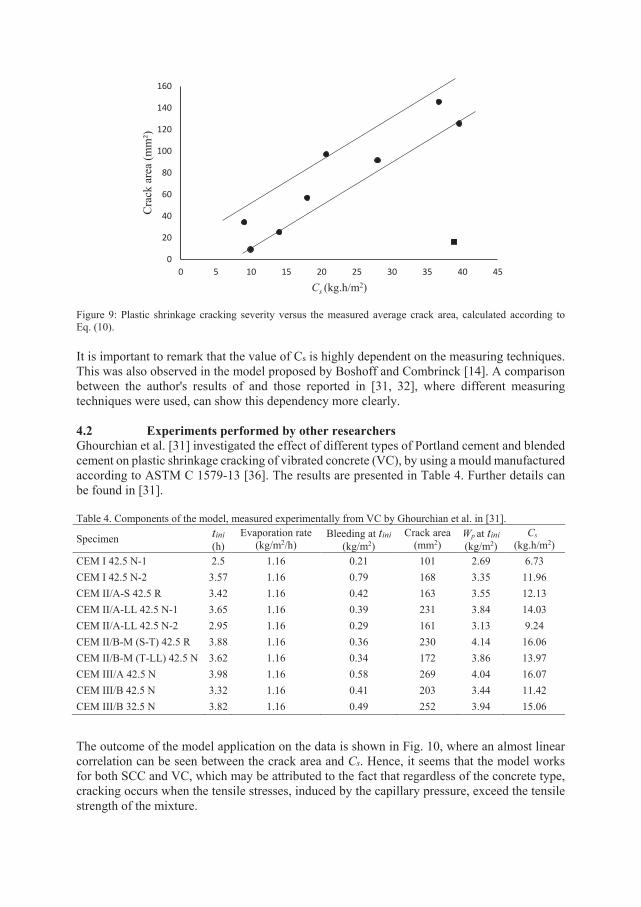
Figure 9: Plastic shrinkage cracking severity versus the measured average crack area, calculated according to Eq. (10).
It is important to remark that the value of Cs is highly dependent on the measuring techniques. This was also observed in the model proposed by Boshoff and Combrinck [14]. A comparison between the author's results of and those reported in [31, 32], where different measuring techniques were used, can show this dependency more clearly. 4.2 Experiments performed by other researchers Ghourchian et al. [31] investigated the effect of different types of Portland cement and blended cement on plastic shrinkage cracking of vibrated concrete (VC), by using a mould manufactured according to ASTM C 1579-13 [36]. The results are presented in Table 4. Further details can be found in [31]. Table 4. Components of the model, measured experimentally from VC by Ghourchian et al. in [31].
Specimen tini (h)
Evaporation rate (kg/m2/h)
Bleeding at tini (kg/m2)
Crack area (mm2)
Wp at tini (kg/m2)
Cs (kg.h/m2)
CEM I 42.5 N-1 2.5 1.16 0.21 101 2.69 6.73 CEM I 42.5 N-2 3.57 1.16 0.79 168 3.35 11.96 CEM II/A-S 42.5 R 3.42 1.16 0.42 163 3.55 12.13 CEM II/A-LL 42.5 N-1 3.65 1.16 0.39 231 3.84 14.03 CEM II/A-LL 42.5 N-2 2.95 1.16 0.29 161 3.13 9.24 CEM II/B-M (S-T) 42.5 R 3.88 1.16 0.36 230 4.14 16.06 CEM II/B-M (T-LL) 42.5 N 3.62 1.16 0.34 172 3.86 13.97 CEM III/A 42.5 N 3.98 1.16 0.58 269 4.04 16.07 CEM III/B 42.5 N 3.32 1.16 0.41 203 3.44 11.42 CEM III/B 32.5 N 3.82 1.16 0.49 252 3.94 15.06
The outcome of the model application on the data is shown in Fig. 10, where an almost linear correlation can be seen between the crack area and Cs. Hence, it seems that the model works for both SCC and VC, which may be attributed to the fact that regardless of the concrete type, cracking occurs when the tensile stresses, induced by the capillary pressure, exceed the tensile strength of the mixture.
0
20
40
60
80
100
120
140
160
0 5 10 15 20 25 30 35 40 45
Cra
ck a
rea
(mm
²)
Cs (kg.h/m2)
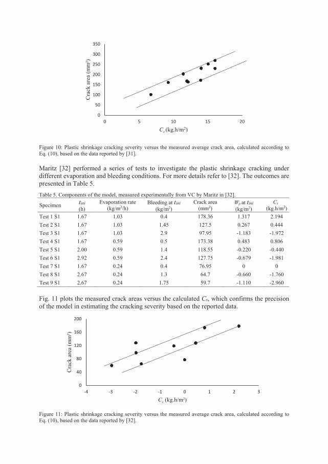
Figure 10: Plastic shrinkage cracking severity versus the measured average crack area, calculated according to Eq. (10), based on the data reported by [31].
Maritz [32] performed a series of tests to investigate the plastic shrinkage cracking under different evaporation and bleeding conditions. For more details refer to [32]. The outcomes are presented in Table 5.
Table 5. Components of the model, measured experimentally from VC by Maritz in [32].
Specimen tini (h)
Evaporation rate (kg/m2/h)
Bleeding at tini (kg/m2)
Crack area (mm2)
Wp at tini (kg/m2)
Cs (kg.h/m2)
Test 1 S1 1.67 1.03 0.4 178.36 1.317 2.194 Test 2 S1 1.67 1.03 1.45 127.5 0.267 0.444 Test 3 S1 1.67 1.03 2.9 97.95 -1.183 -1.972 Test 4 S1 1.67 0.59 0.5 173.38 0.483 0.806 Test 5 S1 2.00 0.59 1.4 118.55 -0.220 -0.440 Test 6 S1 2.92 0.59 2.4 127.75 -0.679 -1.981 Test 7 S1 1.67 0.24 0.4 76.95 0 0 Test 8 S1 2.67 0.24 1.3 64.7 -0.660 -1.760 Test 9 S1 2.67 0.24 1.75 59.7 -1.110 -2.960 Fig. 11 plots the measured crack areas versus the calculated Cs, which confirms the precision of the model in estimating the cracking severity based on the reported data.
Figure 11: Plastic shrinkage cracking severity versus the measured average crack area, calculated according to Eq. (10), based on the data reported by [32].
0
50
100
150
200
250
300
350
0 5 10 15 20
Cra
ck a
rea
(mm
²)
Cs (kg.h/m2)
0
40
80
120
160
200
-4 -3 -2 -1 0 1 2 3
Cra
ck a
rea
(mm
²)
Cs (kg.h/m²)
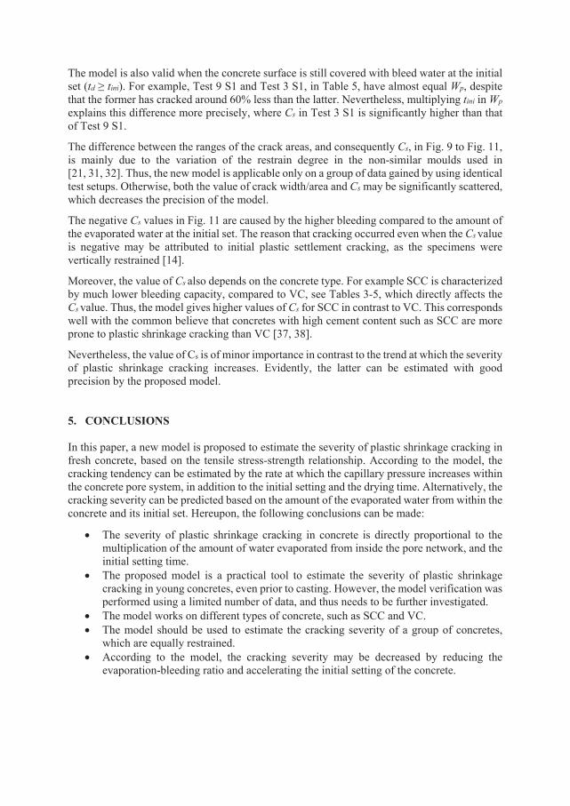
The model is also valid when the concrete surface is still covered with bleed water at the initial set (td ≥ tini). For example, Test 9 S1 and Test 3 S1, in Table 5, have almost equal Wp, despite that the former has cracked around 60% less than the latter. Nevertheless, multiplying tini in Wp explains this difference more precisely, where Cs in Test 3 S1 is significantly higher than that of Test 9 S1.
The difference between the ranges of the crack areas, and consequently Cs, in Fig. 9 to Fig. 11, is mainly due to the variation of the restrain degree in the non-similar moulds used in [21, 31, 32]. Thus, the new model is applicable only on a group of data gained by using identical test setups. Otherwise, both the value of crack width/area and Cs may be significantly scattered, which decreases the precision of the model.
The negative Cs values in Fig. 11 are caused by the higher bleeding compared to the amount of the evaporated water at the initial set. The reason that cracking occurred even when the Cs value is negative may be attributed to initial plastic settlement cracking, as the specimens were vertically restrained [14].
Moreover, the value of Cs also depends on the concrete type. For example SCC is characterized by much lower bleeding capacity, compared to VC, see Tables 3-5, which directly affects the Cs value. Thus, the model gives higher values of Cs for SCC in contrast to VC. This corresponds well with the common believe that concretes with high cement content such as SCC are more prone to plastic shrinkage cracking than VC [37, 38].
Nevertheless, the value of Cs is of minor importance in contrast to the trend at which the severity of plastic shrinkage cracking increases. Evidently, the latter can be estimated with good precision by the proposed model. 5. CONCLUSIONS In this paper, a new model is proposed to estimate the severity of plastic shrinkage cracking in fresh concrete, based on the tensile stress-strength relationship. According to the model, the cracking tendency can be estimated by the rate at which the capillary pressure increases within the concrete pore system, in addition to the initial setting and the drying time. Alternatively, the cracking severity can be predicted based on the amount of the evaporated water from within the concrete and its initial set. Hereupon, the following conclusions can be made:
• The severity of plastic shrinkage cracking in concrete is directly proportional to the multiplication of the amount of water evaporated from inside the pore network, and the initial setting time.
• The proposed model is a practical tool to estimate the severity of plastic shrinkage cracking in young concretes, even prior to casting. However, the model verification was performed using a limited number of data, and thus needs to be further investigated.
• The model works on different types of concrete, such as SCC and VC. • The model should be used to estimate the cracking severity of a group of concretes,
which are equally restrained. • According to the model, the cracking severity may be decreased by reducing the
evaporation-bleeding ratio and accelerating the initial setting of the concrete.
CONFLICT OF INTEREST
There is no conflict of interest.
ACKNOWLEDGMENT The authors would like to gratefully appreciate the financial support they received from the Development Fund of the Swedish Construction Industry, SBUF. Special thanks are also due to the staff of the Thysell lab at Luleå University of Technology.
REFERENCES
1. Lerch, W. (1957) Plastic Shrinkage. ACI Journal 53(8):797-802. 2. Ravina, D. Shalon R (1968) Plastic shrinkage cracking. ACI Journal 65(4):282-291. 3. Powers, T.C. (1968) Properties of Fresh Concrete, John Wiley and Sons, Inc. N. Y., p.
301 4. Slowik, V, Schmidt M, Fritzsch R (2008) Capillary pressure in fresh cement-based
materials and identification of the air entry value. Journal of Cement and Concrete composites 30(7):557-565.
5. Dao V, Dux P, Morris P, O'Moore L. (2010) Plastic shrinkage cracking of concrete. Australian Journal of Structural Engineering. Vol.10, No.3, pp.207-214.
6. Wittmann, F.H., (1976) On the action of capillary pressure in fresh concrete, Cem. Concr. Res. 6, 49–56.
7. Lura, P., Pease, B., Mazzotta, G.B., Rajabipour, F. and Weiss, J., (2007) Influence of shrinkage-reducing admixtures on development of plastic shrinkage cracks. ACI Materials Journal, Vol. 104(2).
8. Radocea, A. (1992) A study on the mechanism of plastic shrinkage of cement-based materials. Chalmers University of Technology.
9. Radocea, A. (1994) A model of plastic shrinkage, Mag. Concr. Res. 46, 125–132. 10. Kwak, H.G., Ha, S.J., (2006) Plastic shrinkage cracking in concrete slabs. Part I: a
numerical model, Mag. Concr. Res. 58, 505–516. 11. Kwak, H.G., Ha, S.J., (2006) Plastic shrinkage cracking in concrete slabs. Part II:
numerical experiment and prediction of occurance, Mag. Concr. Res. 58, 517–532. 12. Cohen, M.D., Olek, J., Dolch, W.L., (1990) Mechanism of plastic shrinkage cracking in
portland cement and portland cement-silica fume paste and mortar, Cem. Concr. Res. 20, 103–119.
13. Ravina, D. and Shalon, R., (1968) Plastic shrinkage cracking, ACI J. 65, 282-292. 14. Boshoff WP, Combrinck R. (2013) Modelling the severity of plastic shrinkage cracking
in concrete. Cement and Concrete Research. 48, pp.34-39. 15. S. Ghourchian, M. Wyrzykowski, P. Lura, (2018) A poromechanics model for plastic
shrinkage of fresh cementitious materials, Cement and Concrete Research 109 120-132. 16. J. Bear, Hydraulics of Groundwater, McGraw-Hill, 1979. 17. Introduction to the Subsurface Flow Module, Comsol AB, Stockholm, 2013. 18. Slowik V, Schmidt M, Fritzsch R (2008) Capillary pressure in fresh cement-based
materials and identification of the air entry value. Journal of Cement and Concrete composites 30(7):557-565.
19. Slowik V, Schmidt M (2010) Early age cracking and capillary pressure controlled concrete curing. Advance in Cement-Based Material 229-234.
20. Sayahi, F. “Plastic Shrinkage Cracking in Concrete”, Licentiate thesis, Luleå University of Technology, 2016.
21. Sayahi, F., Emborg, M., Hedlund, H. and Löfgren, L., (2016) Plastic Shrinkage Cracking in Self-Compacting Concrete: A Parametric Study, International RILEM conference on Materials, Systems and Structures in Civil Engineering, MSSCE 2016, pp. 609-619
22. Dao VTN, Dux PF, Horris PH. (2009) Tensile properties of early-age concrete. ACI Mater J, 106(6):483–92.
23. Hammer, T.A., K. T. Fosså, (2007) Cracking tendency of HSE: Tensile strength and self-generated stress in the period of setting and early hardening, Mater Struct, , 40(3): p. 319-324.
24. J. Abel, K. Hover, (1998) Effect of water/cement ration the early age tensile strength of concrete, Transportation Research Record: Journal of the Transportation research Board, 1610(1): p. 33-38.
25. Ghourchian, S., Wyrzykowski, M., Lura, P., (2017) A Practical Approach for Reducing the Risk of Plastic Shrinkage Cracking of Concrete, RILEM technical letter, 2, , pp. 40-44.
26. Uno PJ. (1998) Plastic shrinkage cracking and evaporation formulas". ACI Mater Journal. Vol.95, pp.365-375.
27. ACI D (1999). 305R-hot weather concreting. American Concrete Institute International,. 28. Josserand, L., Coussy, O., de Larrard, F., (2006) Bleeding of concrete as an ageing
consolidation process, Cem. Concr. Res. 36 1603–1608. 29. Morris, P.H., Dux, P.F., (2010) Analytical solutions for bleeding of concrete due to
consolidation, Cem. Concr. Res. 40, 1531–1540. 30. Carette, J., Staquet, S., (2015) Monitoring the setting process of mortars by ultrasonic P
and S-wave transmission velocity measurement, Const. Build. Mater. 94, 196-208. 31. Ghourchian, S., Wyrzykowski, M., Baquerizo, L., Lura, P., (2018) Susceptibility of Portland
cement and blended cement concretes to plastic shrinkage cracking, Cem. Concr. Compos. 85, 44–55.
32. Maritz, J., (2012) An investigation on the use of low volume—fibre reinforced concrete for controlling plastic shrinkage cracking, MSc Thesis, Stellenbosch University.
33. Johansen, R., Dahl, P., (1993) Control of plastic shrinkage of cement. Proceedings of the 18th Conference on Our World in Concrete and Structures, Singapore.
34. EN 480-4:2005, Admixtures for Concrete, Mortar and Grout. Test Methods, Determination of bleeding of concrete, BSI.
35. Löfgren, I., Esping, O., (2006) Early age cracking of self-compacting concrete. International RILEM Conference on Volume Changes of Hardening Concrete: Testing and Mitigation, Lyngby, 251-260.
36. ASTM C1579-13, (2013) Standard Test Method for Evaluating Plastic Shrinkage Cracking of Restrained Fiber Reinforced Concrete (Using a Steel Form Insert), ASTM International, West Conshohocken, PA.
37. Persson, B., (2005) Plastic shrinkage of self-compacting concrete. In: Jensen, O.M., Geiker, M., Stang, H. (eds.) Proceedings of the Knud Hojgaard Conference, Lyngby, Report R-155 DTU, 43-57.
38. Gram, H.E., Piiparinen, P., (1999) Properties of SCC: Especially early age and long term shrinkage and salt frost resistance. In: Skarendahl, Å., Petersson, Ö. (eds.) Proceedings of the 1st In-ternational RILEM Symposium on Self-compacting Concrete, Stockholm, RILEM Publications S.A.R.L., Bagneux, 211-225.
PLASTIC SHRINKAGE CRACKING IN CONCRETEMitigation and Modelling
Faez Sayahi
Structural Engineering
Department of Civil, Environmental and Natural Resources EngineeringDivision of Structural and Fire Engineering
ISSN 1402-1544ISBN 978-91-7790-344-4 (print)ISBN 978-91-7790-345-1 (pdf)
Luleå University of Technology 2019
DOCTORA L T H E S I S
Faez Sayahi Plastic Shrinkage Cracking in C
oncrete
Related Documents