PLAST IC DESIGN OF BRACED MULTISTORY STEEL FRAMES Published by Committee of Structural St eel Producers Committee of Steel Plate Producers AMERICAN IRON AND STEEL INSTITUTE In cooperation with and editorial collaboration by AMERICAN INSTITUTE OF STEEL CONSTRUCTION

Welcome message from author
This document is posted to help you gain knowledge. Please leave a comment to let me know what you think about it! Share it to your friends and learn new things together.
Transcript

PLASTIC DESIGN OF BRACED MULTISTORY STEEL FRAMES
Published by Committee of Structural Steel Producers
Committee of Steel Plate Producers AMERICAN IRON AND STEEL INSTITUTE
In cooperation with and editorial collaboration by AMERICAN INSTITUTE OF STEEL CONSTRUCTION
It is suggested that inquiries for further informat ion on plastic design be directed to: American Institute of Steel Construction, 101 Park Avenue, New York, New York .10017.
Printed in U.S.A.
Copyright 1968
AMERICAN IRON AND STEEL INSTITUTE 150 East 42nd Street, New York, New York 10017
All rights reserved, including the right of translation and publication in foreign countries.
, 0000 5/68

Foreword
The basic knowledge for the preparation of this design Manual stemmed from the
comprehensive presentation on new developments in t he application of plastic design
principles to the design of multistory steel building frames at the August, 1965 Summer
Conference at Lehigh University. Th is design concept wi ll provide engineers with a greater
insigh t into the actual behavior of multistory frames and will give them an effective too l for
obtaining more econom ica l steel designs.
For the preparation of the Manual, the Committee of Structural Steel Producers and
the Committee of Steel Plate Producers of American I ron and Steel I nstitute retained John
L. Ru mpf, Professor and Head, Civil Engineeri ng and Mechanics, Drexel I nstitute of
Tech nology, as principa l author and Ira M. Hooper and Professor Joseph A. Yura as
co-au thors. For their skillful handling of the assignment, t he Committees grateful ly
acknowledge their appreciation.
The Commit tees also w ish to acknowledge the important and valuable contri bu tion
made by representatives f rom the member stee l producing companies in writing and
reviewing the material for th is Manual.
The material contained in the Manual is presented in two parts, basic design
informat ion and design examples.
Chapters 1 through 3 present the basic design informat ion and background on the
plasti c design method for braced frames. Chapters 4 through 8 describe the design of a
24-story, t hree-bay, braced steel apartment house frame.
Chapter 8 includes all design calcu lations, arranged in a tabular format, with an
explanat ion for each entry. Chapters 4 and 5 describe the subrout ines used to select
members, either for strength or drift cri ter ia. Chapter 6 gives design checks, and Chapter 7
discusses connections.
T he Append ix presents three design aids, and provides a rapid method f.o r checking
lateral-torsional buckling of co lumns.
The concept of plastic design has been documented through a ser ies of research
projects which have been conducted for more than two decades and st ill continue. These
projects have been under the sponsorship of American Iron and Steel Institute, American
Institute of Steel Construction, the Navy Department, the Office of Nava l Research and the
Weldi ng Research Counci l.
Practica l procedu res for the plastic design of continuous beams and one and two-story
rigid frames are described in the American I nst itute of Steel Construction Manual, Plastic Design in Steel_

The American I nstitute of Steel Construction is the non-profit service organization for
the fabricated structural steel industry in the United States and is dedicated to presenting
the most advanced information ava ilable to the technical professions. It is suggested that
inquiries for further information on plastic design be directed to that Institute.
The authors and American I ron and Steel I nstitute wish to express their apprec iation
to all those who assisted in the preparation of the Manual, reviewed the manuscript and
contributed suggestions. In particular, it wishes to thank T. R. Higgins and Professors
George C. Driscoll, Jr., Theodore V. Galambos and Le-Wu Lu.
Committee of Structural Steel Producers
Committee of Steel Plate Producers
American I ron and Steel Institute
Table of Contents
FOREWORD
NOMENCLATURE
CHAPTER 1
1.1
1.2
1.3
1.4
1.5 1.6
1.7
CHAPTER 2
2.1
2.2 2.3
2.4
CHAPTER 3 3.1
3.2 3.3 3.4
INTRODUCTION
Object ive
Contents The Future of Multistory Frames
The Design Team
New Structural Concepts Allowable Stress Design
Plast ic Design
D IMENSIONS AND LOADING
Choice of D imensions Bracing Methods
Gravity Loads
Horizonta l Loads
FUNDAMENTALS OF PLASTIC DESIGN Material Properties. I deal ized Concepts for Beams
Modifying Factors for Beams. Columns
CHAPTER 4 DESIGN OF BRACED BENTS FOR GRAVITY LOADS
4.1
4.2 4.3
4.4
4.5 4.6
4.7
4.8
4.9
Introduction
Descript ion of Bui lding . Wind Bracing
Scope of Design Example
Design of Girders in Bent A
Column Gravity Loads and Moments - Bent A Column Design Assumptions
Design of Columns in Bent A .
Rev iew of Column Design
CHAPTER 5 DESIGN OF BRACED BENTS FOR GRAVITY AND
COMBINED LOADS .
5.1
5.2
Introduction
Design of Braced Floor Girders for Grav ity Loads
Page
1
1 2 2 2
3
3 3 4 4
5 5 5 6 9
13
13 13
13
14 14
15
16
17 20
29 29 30
CHAPTER 5
5.3 5.4 5.5 5.6 5.7 5.8 5.9 5.10 5.11
CHAPT ER 6
6.1 6.2 6.3 6.4 6.5 6.6 6.7 6.8
CHAPTER 7 7.1 7.2 7.3 7.4 7.5 7.6 7.7
CHAPTER 8
REFERENCES
DESIGN AIDS I II I II
TABLE OF CONTENTS (Continued)
(Continued)
Column Gravity Loads Drift Considerations Combined Load Stat ics Calcu lations Drift Equations Behavior of Braced Bents Chord D rift Control Web Dr ift Contro l Design of K-Bracing Story Rotation and Drift
DESIGN CHECKS AND SECONDARY CONSIDERAT IONS Introduction Design Checks, Bent B Checkerboard Loading Deflections at Working Load Sidesway under Gravity Load Spacing of Lateral Bracing . Effect of Shear on Bending Capacity Uplift at Footings, Bent B
CONNECTIONS Introduction Types of Connections Girder-to-Column Connections. Welded Connections Bol ted Connections Column Spli ces .. Bracing Connections .
DESIGN EXAMPLE
Properties of Beam-Columns Beam-Column Moment-Rotation Graphs Beam-Column Interact ion Graphs ... Lateral-Torsional Buckling and In-Plane Bending
Page
32 33 34 36 39 42 44 45 46
49 49 49 50 52 52 54 55 55
57 57 57 58 60 60 60 61
63
97
98 100 106
Nomenclature
A Cross-sectional area. Subscripts b, e, g denote bracing, column and gi rder respectively
Ab Area of bracing member
Abm Minimum K-bracing area (Eq. 68)
Af Area of one flange of girder
As Required area of two st iffeners
B
D
Distance between exterior columns of a bent
Column slenderness ratio at transition from inelastic to elastic buckling
Equivalent moment coefficient
Spacing of braced bents, or distance between the braced bents of a building
E Modulus of elasticity
F Load factor Stress
Axial compressive stress permitted in the absence of bending stress
Fb Bending stress permitted in the absence of ax ial stress
Fer Critical stress for axia lly loaded compression members
Euler buck l ing stress div ided by factor of safety
Specified minimum yie ld point for type of steel being used. Subscripts e, g, S
denote column, girder and stiffener respect ive ly.
FEM Fixed end moment
H
J
Wind load per story
Moment of inertia
Moment of inertia of vertica l bracing truss chords
K Effective length factor
Kb Ratio of actual K-bracing area to minimum K-bracing area
L Distance between centerlines of vertical bracing truss chords
Length of bracing member
Length of clear girder span
LTB Lateral -Torsional Buckling
M Bending moment
Moment at the ends of girder under facto red dead load
Moment at the ends of a girder under factored gravity load
Plastic moment required for mechanism in the absence of an axial load
Uniform moment about major axis causing lateral-to rsional buckling of the member in the absence of a co ncentric load
Plastic moment (Fy Z)
Mpc Plastic moment modified to include the effect of ax ial compression
Moment about the center of a joint. Subscri pts A . B. U and L denote left end of gi rder. right end of gi rder. upper end of column. and lower end of co lumn. respectively
Moment about center of jOint caused by eccentr ica lly f ramed members
Moment at f irst y ield (FyS)
M I .M 2 Peak beam-co lumn moment capacity from M-O curves
M " Moment caused by PIl effect
N
P
Number of braced bays
Axia l load
T ota I shear ina story
Axial f orce in bracing members. Subscripts H and V denote horizonta l and vert ical components of force
A xial load in co lumns due to w ind and PIl effect
Critica l concentric buckl ing load
Major axis co ncent ric Euler buckl ing load
Axia l force in gi rder
Pox Major ax is concent r ic buck ling load
Minor ax is concentr ic buck li ng load
L imit ing load
Tota l working gravity load above a story
Plast ic ax ial load. AFy
Q"
R
S
T
V
w
z
b
d
e
Iv
h
Shear caused by PIl effect
Tota l rotation in a story (sum of chord and web rotat ion) = !l/h Live load reduction factor.
Rotation in a story due to brac ing length changes
Chord rotat ion in a story due to column length changes
Rotation in a story due to gi rder length changes
Web rotat ion in a story due to girder and bracing length changes
Elast ic section modulus
Tensile f lange fo rce
Shear fo rce
Shear f orce t hat causes the web to yield in shear
Worki ng wind shear at a st ory
Plast ic section modulus
Widt h of f lange
Width of st iffener
Depth of sect ion. Subscript s c and g
denote co lumn and girder depth. respectively
Axial change in length. Subscript b denotes change of length of brac ing
Computed shear stress
Story height
Total height of braced bent
k
I
Distance from outer face of flange to toe of web fillet Proportionality factor for drift calculation
Length of member Length of unbraced beam segment
Icr Critical unbraced length
n Number of level or story (Roof = 1)
q Ratio of column end moments
r Radius of gyrat ion. Subscripts x and y
refer to major and minor axis, respectively
t Flange or plate thickness. Subscripts c, g and s denote column, girder and stiffener, respectively
W Working gravity load (dead plus live load) Web thickness
Total equ iva lent factored horizontal load, w ind plusPC. effects (Eq. 5.15)
Column web th ickness
Wd Working dead load
Average working gravity load over the entire bu ild ing
WI Work ing I ive load
Uniformly distributed unit load corresponding to formation of a plastic mechanism in a fixed end beam
Working wind load
Equivalent factored horizonta l load, Pc. effects (Eq . 5 16)
Chord angle change in a story
O! a Chord angle change above a story
Drift. Subscripts b, C, g refer to bracing, column and girder respectively
C.c Chord drift in a story
Total drift at top of bent
C.W Web drift in a story
E
e
Maximum deflect ion of a simp ly supported beam
Strain
Strain at onset of hardening
Strain at yield po int
End slope Slope of d iagonal stiffeners
l;6P Total factored gravity load increment appl ied at each level
¢ Curvature
¢b'se Curvature at bottom story
Curvature corresponding to moment at first yielding

CHAPTER 1
Introduction
1.1 OBJECTIVE
The objective of this publicat io n is to acquaint practicing engineers with the present state of the theory for the plastic design of braced mu It istory steel frames. I t is hoped that the inf ormation presented wil l stimulate the use of plastic design methods for frames of t his type, and that this in turn will produce an input of useful ideas contributing to the fu ll development of the concept.
1.2 CONTENTS
The information contained herein is main ly a digest of the research material presented to eng ineering educators at the Lehigh University Conference on Plastic Design of Mu ltistory Frames l in August 1965. An effort has been made to include enough theory for the eng ineer to understand the behavior of t he structure but to concentrate principally on design aspects. The engineer who wishes to delve into the background of research should study the references listed. The design example of a braced mu Itistory frame will serve as a guide to the efforts of the practicing engineer as he applies the principles of plastic design to his own work. The grades of steel used in the design example are A36 w ith Fy ~ 36 ksi and A441 or A572 with Fy ~ 50 ksi. Design aids for these values are included. A listing of the notation used is given for ready reference. Sign conventions are discussed as they are developed.
1.3 THE FUTURE OF MU LTISTORY FRAMES
Multistory and high-rise bui ldings have been common in some of our nation's large cities, but
recent sociolog ical t rends have forced the use of such structures in more numerous locations and have pushed them to even greater heights. As the population increases and tends to concentrate in urban areas, and as land costs skyrocket, the multistory building becomes t he economica l solu ti on to housing people for living and working. The tall build ing w ill be the common structure of the future and economy of the structura l frame is of increasing importance. Structural steel frames proportioned by plastic design methods may offer savings over frames of other materials and over stee l f rames designed by al lowable stress methods.
14 THE DESIGN TEAM
Regardless of the design method, the bu ild ing process today demands an integrated team of architects, and electrical, mechanical and struct ural engineers. Each must understand the other's requirements, for rising costs and increased demand for excellence in construct ion require the integration of all building components into a compact structure with a minimum of wasted volume. The structural engineer must understand the architect's desire to have t he structural frame complement the function and t he motif of the building. He must be appreciative of the space needed for the conduits and ducts required by the electrical and mechanical engineers as they attempt to regulate the in terna l environment of the modern building. With in such constraints he must produce a safe and economical structural f rame. The frame must safely support the gravity and wind loads withou t undue deflection or sway affect ing the operation of other building components or producing unpleasant sensations to the occupants.
2
1.5 NEW STRUCTU RA L CONCEPTS
Fortunately, the structural engineer is assisted in fulfilling these requirements by new knowledge of how structures behave, and by t he advent of new mater ials, products and construction techn iques. Research on the behavior of stee l structures du ri ng the last twenty years has led to the development of the plastic design philosophy as contrasted to the more established methods of elast ic design, more correctly known as allowable stress design. Composite design uses the integrated strength of stee l and concrete. New high strength structural stee ls of carbon, low alloy and heat treated types permit a reduction in the sizes of members. High strength bolt s and new welding techniques produce econom ical, r igid connect ions of greater compactness and more di rect transfer of stress.
1.6 AL LOWABLE STRESS DES IGN
The current method of designing rigid multistory bu ild ing frames 2 involves the determ ination of t he interna l shears, moments and thrusts caused by work ing loads using methods of allowable st ress analysis for statical ly indeterminate structu res. Because of the high order of redundancy of the mu ltistory r igid f rame the analysis is usually reduced to a statical one by mak ing appropriate assumpt ions as in the "porta l" or "cant ilever" methods. Using the internal forces and an al lowable stress, derived principa lly by dividing the y ield po int st ress of the stee l by a facto r of safety, the members are proport ioned using ordinary mechanics of materia ls equations. I nherent in this approach is t he phi losophy t hat t he limit of usefulness of the structure is reached as soon as the yield point stress is developed at one poin t in the f rame. Other poin ts in the frame wi ll be understressed, and thus uneconomical in the use of material. This method does not recognize that local yielding in a r igid ly connected stee l structure permits a red istr ibution of the internal
forces to less high ly stressed parts of the structu re, and consequently it underestimates the load carry ing capacity of the st ructure as a whole. Local y ielding is not detrimenta l to the behavior of the structure prov ided it is contained by adjacent elast ic regions of the frame.
1.7 PLASTIC DESIGN
On the other hand, the plast ic design philosophy recognizes the redistr ibut ion of interna l forces that takes place when comp lete y ielding (p last ic hi nges) develops at reg ions of high bending moment. It focuses on the limit of usefu lness as the ultimate load that can be carried just before the structure develops a suff icient number of plast ic hinges to permi t unrestrained deformat ion of t he st ructu re. Th is ult imate load is an ind ication of t he st rength of the whole structu re, and it exceeds the work ing load by a factor F. The quanti ty F, ca lled the load facto r, is se lected to be consistent with the factors of safety inherent in the al lowab le stress design of a simply supported beam. I n this publication the fo llowing va lues, adopted from the Lehigh Conference, are used fo r beams, columns and frames:
Gravity load ing Gravity and wi nd load ing
F = 1.70 F = 1.30
Uncerta inty about stabili ty problems was the ch ief reason for a somewhat higher load factor specified for frames in the past . 3 New research presented at the Lehigh Conference has led to a better understand ing of the behavior of columns and therefore the values of F shown appear justif ied.
Defl ection may also constitute a limit of usefulness for the structure, and whether designing by al lowable st ress or plast ic methods, it is necessary to consider t he vertica l beam def lect ions and horizontal frame deflect ions (dr ift) under working loads. Deflections rather than strength may actual ly govern t he design.
3
CHAPTER 2
Dimensions and Loading
2.1 CHO ICE OF DIMENSIONS
The overa ll dimensions of the mu lt istory bu ilding are governed by the size and shape of the site ava ilable and by set-backs f rom the property lines requi red by zoning ordinances. For reasons of arch itectura l layout it is often advantageous for the bu ild ing to be long and narrow. Within these area limitat ions it is t he responsib i lity of t he arch itect -engineer design team to determine t he required number of floors to fu lfi l l the owner's space needs. Many municipa lities have zoning ordinances restr ict ing heights of bui ldings, but these restr ictions are be ing removed or liberal ized as codes are rev ised .
The design team must decide on bay sizes fo r t he structu ral frame that fit the arch itectural and mechan ical -electr ical layouts of t he integrated structu re o There is a t rend toward t he use of larger bay dimensions, particu lar ly w ith composite floor beams. Longer spans increase the depth of the f loor system, thereby increasing the height of the bu ilding. However, increased f loor depth of ten permits more economical construct ion even though the building volume is increased.
Regard less of the method of st ru ctural design , the items ment ioned above must be considered and examined f rom thei r techn ical and economical aspects before bay sizes are establ ished. T he bay sizes shown for the apartment house example of Chapter 8 represent a possible, but not necessar il y t he best , f ram ing plan for that st ructu re. They represent a comp romise based on the integrated requi rements.
2.2 BRAC ING METHODS
The mu Itistory build ing must be designed to provide resistance to hor izonta l forces app lied in any direct ion. A number of devices may be used,
includ ing shear wa l ls or core sect ions, but in the example in Chapter 8 attent ion wil l be directed toward proport ion ing of the stee l bents to prov ide t he necessary strength and lim itation to dri ft . There are two convent ional methods of provid ing t he necessary resistance.
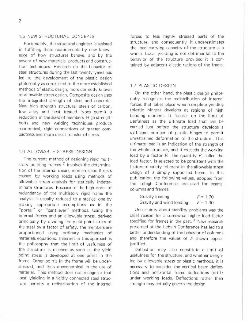
One or more bents of a frame may be braced fo r the fu ll height of the building using diagona l or K-bracing. This creates a verti cal cantilever truss to wh ich all wind load is t ransm itted. In t he al lowable stress design of th is type of f raming the girders may have either simp le or rigid connections to the co lumns. Plast ic design requires r igid connections. Rigid con nect ions have real advantages in allowable stress design also. For examp le, r igidly connected members reduce beam deflect ions, reduce beam depth, and reduce floor crack ing .
PORT ION OF BENT
! P, Resultant load ~ above story
44 y- ~-
+ + ISOLATED QNE·STORY COLUMNS
FIG 2.1 T HE Pc, EFFECT DUE TO SWA Y
4
On the other hand, resistance to t he horizontal forces may be provided entirely by the bending resistance of rigidly connected girders and columns.
It is desirable to define braced and unbraced bents in terms of the method of resisting secondary moments produced by drift. When a bui ld ing drifts, each floor moves laterally with respect to the adjacent floors as ind icated in Fig. 2.1. The vert ical forces kP on the columns at one floor become eccentric w ith respect to the column axes at t he floor beneath by an amount tl, producing secondary moments totaling Ptl.
In this publication the following def initions and assumptions wi ll be used:
Braced Bent - Has physical brace in at least one bay of a bent on each floor. Ptl effect is controlled by the shear resistance of the braci ng system. Girder connections are rig id.
Unbraced Bent - No physical brace. Strength depends on bend ing resistance of all members. Ptl effect must be resisted by the columns in bending. Girder connections are rigid
Supported Bent - Depends on adjacent braced or u nbraced bents for resistance to hori zontal forces and Ptl effects; is designed for gravity loads only. Girder connections are rigid .
2.3 GRAVITY LOADS
Bui lding codes spec ify the working live loads for f loors, the roof load and wind loads. The dead load, floor live loads and roof loads are referred to as gravity loads. Although the dead load is always present many variable patterns of live loading are possib le. Codes 4 permit a reduction in t he live load for beams or gi rders support ing large floor areas and for columns support ing several tiers of floors. Such reductions recogn ize the improbability of hav ing the ful l live load acting over large areas and on all floors simultaneously.
Partial live loading in a checkerboard pattern may contro l the column design. Checkerboard loads produce a lower axia l force in the columns but may produce a more critical bending effect.
2.4 HORIZONTAL LOADS
Wind loads are usually expressed as a resultant unit pressure applied horizontally aga inst the windward side of the bu ilding. Many modern codes require an increase in wind pressure as the height above the ground increases. It is customary t o convert the wind pressure to fo rces applied at each floor leve l, and to assu me that the f loors, act ing as diaphragms, transfer the wind forces along the build ing to the period ica lly spaced braced frames.
The appl icat ion of plastic design to seismic load ing is an area of current study 5
5
CHAPTER 3
Fundamentals of Plastic Design
3.1 MATERIAL PROPERTIES
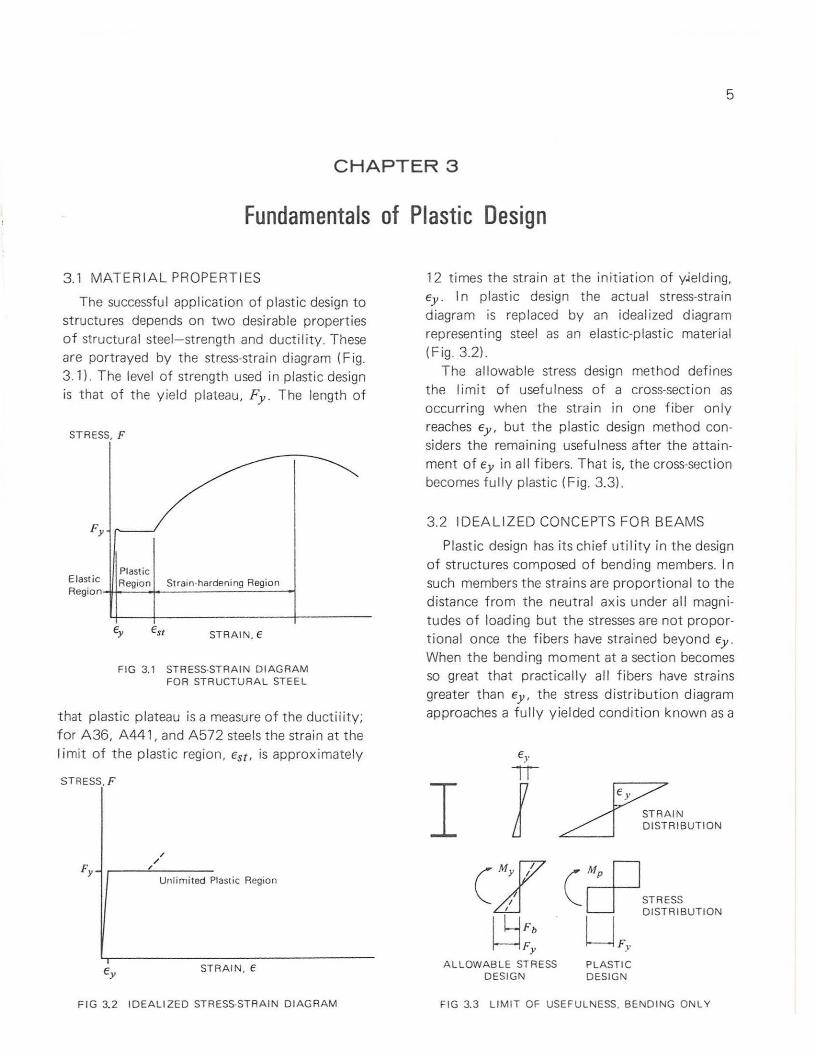
The successful application of plastic design to structures depends on two desirable properties of structural steel-strength and ductility. These are portrayed by the stress-strain diagram (Fig. 3.1) The level of strength used in plastic design is that of the yield plateau, Fy . The length of
STRESS, F
Plastic Elastic Region Strain-hardening Region Aeg;on4l+"':::~t--====2..:==-I
STRAIN. E
FIG 3.1 STRESS·STRAIN DIAGRAM FOR STRUCTURAL STEEL
that plastic plateau is a measure of the ductility; f or A36, A441, and A572 steels the strain at the limit of the plastic region , Est, is approximate ly
STRESS.F
, / ,
Unlimited Plastic Region
STRAIN, €
FIG 3.2 IDEALIZED STRESS-STRAIN DIAGRAM
12 times the strain at the initiation of y;e lding, Ey. In plastic design the actual stress-strain diagram is replaced by an idealized diagram representing steel as an elastic-p lastic material (Fig 32)
The al lowable stress design method defines the limit of usefulness of a cross-section as occurring when the strain in one fiber only reaches Ey , but the plastic design method considers the remain ing usefulness after the attainment of Ey in all fibers. That is, the cross-section becomes fully plastic (Fig. 3.3)
3.2 IDEALIZED CONCEPTS FOR BEAMS
Plast ic design has its chief utility in the design of st ructures composed of bending members. In such members the strains are proportional to the distance from the neutral axis under all magnitudes of loading but the st resses are not proportional once the fibers have strained beyond Ey.
When the bending moment at a section becomes so great that practically all fibers have strains greater than Ey, the stress distribution diagram approaches a fully yielded condition known as a
I STRAIN DISTRIBUTION
STRESS (crp
. U F,. DISTRIBUTION
ALLOWABLE STRESS DESIGN
PLASTIC DESIGN
FIG 3.3 LIMIT OF USEFULNESS. BENDING ON LY
\ \
8
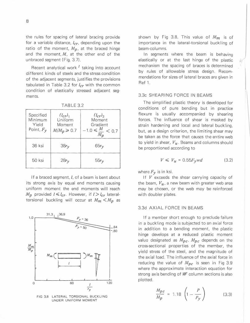
the rules for spac ing of lateral bracing prov ide for a var iable distance, ler, depending upon the ratio of the moment, Mp , at the braced hinge and the moment, M, at the other end of the unbraced segment (Fig 37).
Recent analytical work J taking into account different k inds of steels and the stress condit ion of the adjacent segments, justif ies the provisions tabulated in Table 3.2 for ler with the common condition of elast ica l ly stressed adjacent segments.
TABLE 3.2
Specified (tcr)l (ter)2 Minimum Uniform Moment
Yield Moment Gradient Point, Fy M/Mp;;;' 0.7 - 10.;;;M < 0.7 . -
Mp
36 ksi 38ry 65ry
50 ksi 28ry 55ry
I f a braced segment, I, of a beam is bent about its strong axis by equal end moments causi ng uniform moment the end moments will reach Mp provided I';;; ler. However, if I > ler lateral torsional buckling will occur at Mm <Mp as
a
_ .B4 -.BO
60 120
'y
FIG 3.B LATERAL TORSIONAL BUCKLING UNDER UNIFORM MOMENT
shown by Fig 3.8. This value of Mm is of importance in the lateral-t orsional buckling of beam-co lumns.
I n segments where the beam is behaving elastically or at the last hinge of the plastic mechanism the spacing of braces is determ ined by ru les of allowable stress design. Recommendations for sizes of lateral braces are given in Ref 1.
3.3c SHEARING FORCE IN BEAMS
The simpl ified plastic theory is developed for condit ions of pure bending bu t in practice fl exure is usually accompan ied by shearing forces. The influence of shear is masked by strain hardening and local and latera l buckling, but, as a design criterion, the l im iting shear may be taken as t he force that causes the entire web to yield in shear, Vu. Beams and columns should be proportioned according to
v .;;; Vu = 0.55Fywd (32)
where Fy is in ksi. If V exceeds the shear carry ing capacity of
the beam, Vu , a new beam w ith greater web area may be chosen, or the web may be re inforced with doubler plates.
3.3d AXIAL FORCE IN BEAMS
If a member short enough to preclude failure in a buckling mode is subjected to an axial force in addition t o a bending moment, the plastic hinge develops at a reduced plastic moment value designated as Mpe . Mpc depends on the cross-sectional properties of the member, the yield stress of the steel, and the magnitude of the axial load. The inf luence of the axial fo rce in reducing the value of Mp c is seen in Fig 3.9 where the approx imate interaction equation for strong axis bending of V1F column sections is also plotted .
118 (1 -.!:..) Py (3.3)
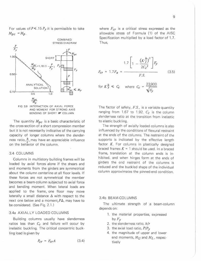
For values of P';;' .15 Py it is permissible to take
Mpe =Mp .
1.00
0.50
, "
ANALYTICAL '\ SOLUTION\
\
COMBINEO STRESS DIAGRAM
0.15 '-----:'-;------:"::-0.5 1.0
~c p
FIG 3.9 INTERACTION OF AXIAL FORCE AND MOMENT FOR STRONG AXIS
BENDING OF SHORT W COLUMN
The quant ity Mpc is a basic characteristic of the cross-section of a short compression member but it is not necessarily indicative of the carry ing capacity of longer columns where the slenderness ratio,...!!., may have an appreciable influence on the beh~vior of the column.
3.4 COLUMNS
Columns in mult istory bui lding frames wil l be loaded by ax ial forces alone if the shears and end moments from the girders are symmetrical about the co lumn centerline at all floor levels. If these forces are not symmetrical the member becomes a beam-column subjected to axial force and bend ing moment. When lateral loads are applied to the frame, one floor may move lateral ly a small distance t. with respect to the next one below and a moment,Pt., may have to be considered. (See Fig. 2.1.)
3.4a AXIALLY LOADED COLUMNS
Build ing co lumns usually have slenderness ratios less than Cc and failure wi ll occur by inelastic buckling. The critical concentric buck
I ing load is given by
Per = FhA (3.4)
9
where Fer is a critical stress expressed as the allowable stress of Formula (1) of the AISC Specification multiplied by a load factor of 1.7. Thus,
1.7 [1
F'cr 1.7 Fa
_ (K r) Fy h 2J 2C 2 e
FS.
for K ~ ,;;, c;, where Cc 23,900
~
(3.5)
The factor of safety, FS., is a variable quantity ranging from 1.67 to 1.92. Ce is the co lumn slenderness ratio at the transition from inelastic to elast ic buckling.
The strength of axially loaded columns is also influenced by the cond itions of flexural restraint at the ends of the columns. The restraint of the supports is indicated by the effect ive length factor K. For columns in plastically designed braced frames K = 1 should be used. In a braced frame, translation at the column ends is inhibited, and when hinges form at the ends of girders the end restraint of the columns is reduced and the buckled shape of the individual column approximates the pinned-end condit ion.
3.4b BEAM-COLUMNS
The ultimate strength of a beam-column depends on:
1. the material properties, expressed byFy
2. the slenderness rat io, hlr 3. the ax ial load ratio, PIPy 4 . the magnitude of upper and lower
end moments, M U and M L, respectively
10
5. the direct ion of the end moments expressed by q, the ratio of the numerically smaller to the numeri ca lly larger end moment
The ultimate strength of beam-columns may be represen ted by moment-rotat ion curves or by interact ion curves. Both procedures will be described briefly.
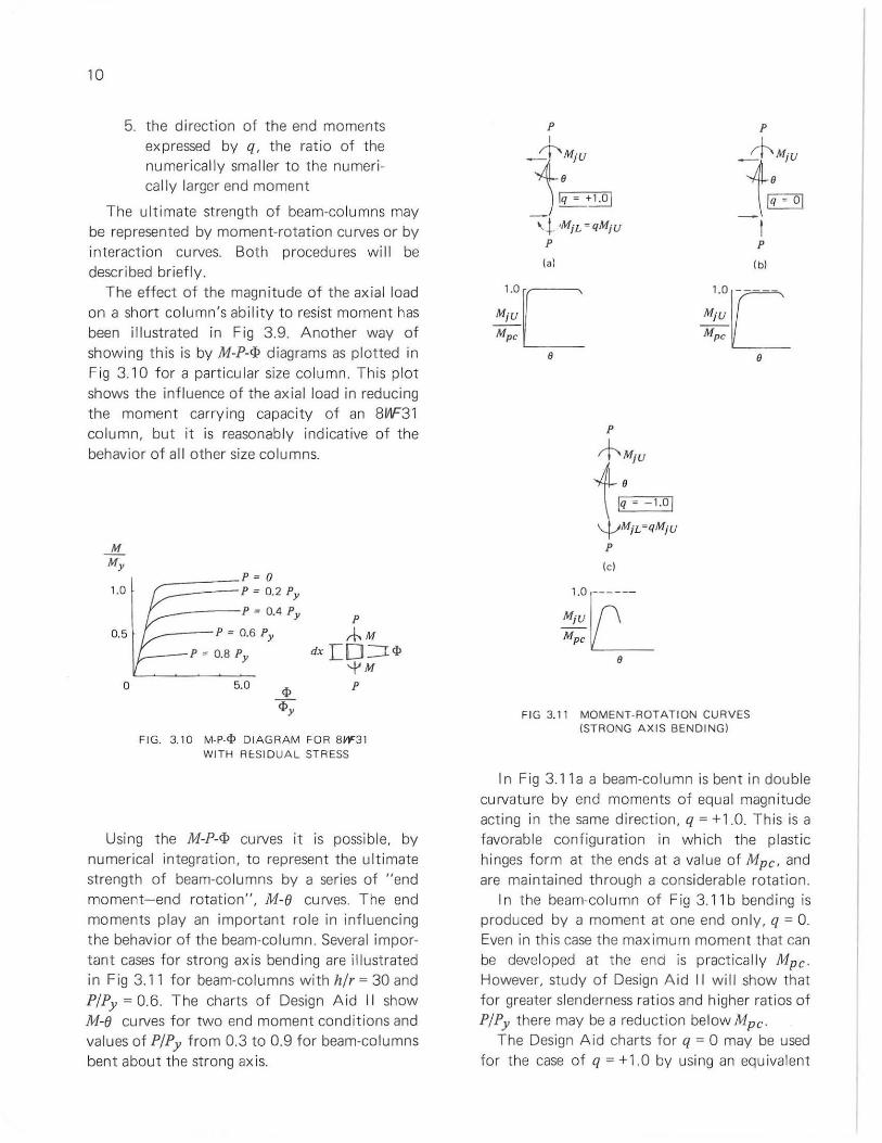
The effect of the magn itude of the axia l load on a short co lumn's abil ity to resi st moment has been illustrated in Fig 3.9. Another way of showing this is by M-P-if> diagrams as plotted in Fig 3.10 for a particular size column. This plot shows the infl uence of the axia l load in reducing the moment carrying capacity of an 8f1F31 column, but it is reasonab ly indicative of the behavior of all other size columns.
M My
1.0
0.5
o
-=:::===P= 0 , P=0.2Py
~_---P = 0.4 Py
~---P = 0.6 Py
I_--P = O.B Py
5.0
P ,-hM
dx r:: 0 :=r <I> '-J'M P
FIG. 3.10 M·P.</> DIAGRAM FOR BW31 WITH REoSIDUAl STRESS
Using the M-P-if> curves it is possible, by numerical integration, to represent the ult imate strength of beam-columns by a series of "end moment-end rotation" , M-e curves. The end moments play an important role in influencing the behavior of the beam-column. Several important cases for strong axis bending are illustrated in Fig 3.11 fo r beam-columns wi th hlr = 30 and PIPy = 0.6. The charts of Design Aid II show M-e curves for two end moment conditions and values of PIPy f rom 0.3 to 0.9 for beam-columns bent abou t the strong ax is.
P I
~MjU
J~+~ ~t ,MiL = qMjU
P
(al
P
+MjU
t=I:-=-'1.",O I '{-'MiL =qMjU
P
(e)
P
......cf-MjU
!~ I P
(bl
M;:C----Mpe
e
FIG 3.11 MOMENT· ROTATION CURVES (STRONG AXIS BENDING)
I n Fig 3. 11 a a beam-column is bent in double curvature by end moments of equa l magn itude acting in the same direction, q = +1.0. This is a favorable configurat ion in which the plast ic hinges form at the ends at a value of Mpc , and are maintained through a considerable rotation.
I n the beam-column of Fig 3.1 1 b bend ing is produced by a moment at one end on ly, q = O. Even in this case the maximum moment that can be developed at the end is practically Mpc. However, study of Design A id II will show tha t for greater slenderness ratios and higher ratios of PIPy there may be a reduction below Mpc.
The Design Aid charts for q = 0 may be used for the case of q = +1.0 by using an equ ivalent
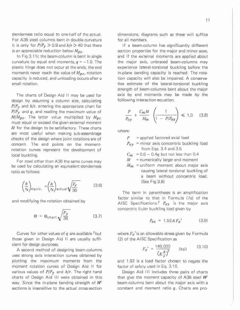
slenderness ratio equal to one-half of the actual. For A36 steel columns bent in double curvature it is only for PIPy > 0.9 and hlr > 40 that there is an appreciable reduction below Mpc .
In Fig 3.1 1 c the beam-column is bent in sing le curvature by equal end moments, q = -1.0. The plastic hinge does not occur at the ends, the end moments never reach the va lue of Mpc , rotation capacity is reduced, and unloading occurs after a small rotation.
The charts of Design Aid II may be used for design by assum ing a co lumn size, calcu lating PIPy and hlr, entering the appropriate chart for PIPy and q, and reading the maximum value of MIMpc. The latter value multipl ied by Mpc must equal or exceed the given external moment M for the design to be satisfactory. These charts are most usefu l when making sub-assemblage checks of the design where joint rotations are of concern. The end points on the momentrotation curves represent the development of local buckling.
For steel other than A36 the same cu rves may be used by ca lculating an equivalent slenderness ratio as fo llows:
=(!!:..) r;;-rx aClualV36"
(3.6)
and modi fying the rotation obtained by
!F; 8 = 8 chart V 36 (3.7)
Curves for other values of q are avai lable 1 but those given in Design Aid II are usually sufficient for design pu rposes.
A second method of design ing beam-columns uses strong axis interaction curves obtained by plott ing the max imum moments from the moment rotation curves of Design A id II for various values of p/Py and hlr The right hand charts of Design Aid III were obta ined in this way. Since the in-plane bending strength of W' sections is insensitive to the actual cross-section
11
dimensions, diagrams such as these will suffice for all members.
If a beam-column has significantly different section properties for the major and minor axes, and if the external moments are app lied about the major axis, unbraced beam-columns may experience lateral-torsional buckl ing before the in-plane bend ing capacity is reached. The rotation capacity will also be impaired. A conservative estimate of the latera l-torsiona l buck l ing strength of beam-co lumns bent about the major axis by end moments may be made by the fol lowing interaction equation.
+--Pay Mm
( 1 J,;;; 1.0 ~ - PIPex)
(3.8)
where:
P = appl ied factored axial load Pay = minor axis concentric buckling load
from Eqs. 3.4 and 3.5 em = 0.6 - O.4q but not less than 0.4 M = numerically larger end moment Mm = uniform moment about major ax is
causing lateral -torsional buckling of a beam without concentric load. (See Fig 3.8)
The term in parentheses is an amplification factor similar to that in Formula (7a) of the AISC Specifications3 Pex is the major axis concentric Euler buckling load given by
Pex = 1.92A Fe' (3.9)
where Fe ' is an allowable stress given by Formu la (2) of the AISC Specification as
F' - 149,000 e - (K!!.}
r
(ksi) (3.10)
and 1.92 is a load factor chosen to negate the factor of safety used in Eq. 3.10.
Design Aid III includes three pairs of charts that give the moment capac ity of A36 steel W' beam-columns bent about the major axis with a constant end moment ratio q. Charts are pro-
12
vided for double curvature bending (q = +1.0), one end pinned (q = 0)' and single curvature bending (q = - 1.0).
The f irst chart of each pair is based on the lateral -torsional buck ling (LTB for brev ity) moment capacity derived from Eq. 3.8 f or spec ified va lues of h/ry.
The LTB charts assume that the beam-column IS braced abou t both axes only at its ends and that rx / ry = 1.7, which is a common ratio for we co lumns of width equal t o depth; other light sect ions have higher va lues of rx / ry . These charts give slightly conservative va lues of Eq. 3.8 for we co lumn s with rx /ry > 1.7. The intercepts of the h/ry curves on the load (P/Py ) ax is are the ra tios Poy /Py where Poy is the minor ax is buckling load from Eq. 3.4. Hence, t he LTE charts automatica lly provide a check for minor axis column buckl ing due to concentric load.
The second chart is based on the max imum in-plane bending moment capacity determ ined
from the peaks of the M-e curves for specif ied values of h/rx in Design Aid II.
The horizontal coordinate axis of the interact i on charts indicates the beam-co lumn moment capac ity in the form M/Mpc. The reduced plast ic moment Mpc from Eq 3.3 is an upper bound on the moment capacity of we beam-columns bent about t he major axis. Note that the ax ial load ratio P/Py is used both to enter the interaction charts and to determine
Mpc. Design Aids II and III may be used for steels
with other values of Fy by entering the curves with an equivalent slenderness ratio from Eq 3.6 and by modifying the end rotation e using Eq 3.7.
The M- e curves in Design Aid II are based on in-plane behavior only. If the beam-column
moment exceeds the lateral-torsional buckling moment capacity from Design Aid III, lateral brac ing must be provided to ensure in-plane behavior. If the beam-co lumn is unbraced between its ends, t he M- e curve is valid only for moments less t han the lateral-torsional buckling moment. For an unbraced beam-co lumn in single curvature bending (q = - 1.0), lateraltorsiona l buck ling always limits the maximum moment capac ity to a va lue be low the peak of the M- e curve. I n the more usual case of double curvature bending (q = +1. 0), the maximum in-plane moment capac ity of an unbraced beamcolumn can frequ ent ly be attained without lateral-torsional buck ling, depending on the minor axis slenderness h/ry and the axia l load ratio P/Py .
The behavior of beam-columns illustrated by the M- e curves of Design Aid II w ill not develop if a loca l buckle of the f lange or web occu rs. To prevent an early occurrence of local buckling the wid th-thickness ratio of the component parts must be limited to certain values as shown in Tab le 3.3.
TABLE 3.3
Specified Minimum Flange Web
Yield bit d/w Point, Fy
70- 100 P/Py 36 ksi 17.4 but need not be
less than 43
60- 85P/Py 50 ksi 14.8 but need not be
less t han 36
13
CHAPTER 4
Design of Supported Bents for Gravity loads
4.1 INTRODUCTI ON
This is the first of several chapters which i llustrate the plastic design of a bra'ced multi story bu ilding . Included in t his chapter are a description of the building to be designed and the scope of the design example. Th is is fol lowed by an explanation of the design of a multistory ben t f or full gravity loads. The design ca lculat ions f or the example descri bed here are grouped together in Chapter 8 for easy reference.
4.2 DESCR IPT ION OF BU ILDI NG
The plastic design example concerns a 24-story apartment building . Prelirninary structural plans are summarized in Fig. 8.1. The main st ructural elements are 3-bay rigid bents with AISC Type 1 (rig id) girder-to-column connections, spaced 24 ft. apart . The floor framing includes a 2Y, in. lightweight concrete slab on a corrugat ed steel form supported by open web stee l jo ists. Tie beams and spandrels between the rigid bents are framed to t he columns using AISC Type 2 (simple) connections. This structural system causes col umn moments from grav ity loads to occur only in the plane of the rigid bents.
Section A-A in Fig . 8.1 indicates an 8 ft. clear ceil ing height and a construction depth of 1 ft. -8 in . These give a story height of 9 ft. -8 in. except in t he bottom two stories where the height is increased to 12 ft. A depth limitation of 14 in. is set for t he rigid frame girders to maintain a f lush ce iling in contact with the bottom chord of the steel joist s.
The numbering system used to identify members in the design calcu lations is shown in Fig. 8.1. T he column l ines are numbered 1 to 4 and the floor levels are numbered from the roof
down. The letters A and B designate individual r igid bents.
The lower portion of Fig. 8.1 summarizes the work ing loads. To simplify the numerical work, the f loor loads in the 8 ft. corridor are applied over the fu ll 12 f t . w idth of the interior bay between column l ines 2 and 3.
The intent of th is example is to illustrate the appl ication of p lastic design concepts t o a practical building prob lem. The framing in Fig. 8.1 is one of severa l practical structu ral solutions for th is building and should not be regarded as an optimum structural system.
4.3 WIND BRACING
The size and shape of the build ing in Fig. 8.1 suggest that resistance to wind is an irnportant structural considerat ion. Vertica l bracing is usually the most economical solution when archi tectural requirements permit its use. It is important to give early considerat ion to the integration of arch itectu ral and structu ral requirements so that a vertica l bracing system can be incorporated into the walls of a build ing. If possible, the vert ica l bracing system shou ld be symmetr ical in plan to avoid torsional effects.
The dashed l ines on the floo r plan in Fig. 8. 1 indicate the vertical bracing system used in this design example. Vertica l brac ing is located in the exterior wa lls on column lines 1 and 4 to carry wind loads acti ng on the short side of the building. As an alternative, the exterior masonry wa ll s can be used to resist wind on the short side of the building. The stiffness of these walls may resist a porti on of the w i nd shear even if vertical bracing is provided . K-bracing is used in t he exter ior bays of t hree rigi d bents to resist wind acting on the long sides of the building.
14
The plastic design examp le considers the design of the supported Bents A and braced Bent B shown on the floor plan in Fig B.1. No vertical bracing is provided in the supported Bents A which are designed to carry only gravity loads. Horizontal forces are transmitted from Bents A by diaphragm action of the floor slab, to Bent B. The K-brac ing in the plane of Bent B is assumed to resist the horizontal shears from wind on a 96 ft. length of the build ing and to provide the stiffness needed to resist in-plane frame instabi lity (pt. effects, see Chapter 2 and Art. 5.4) for three Bents A and one Bent B. I nterior parti tions enclose the K-bracing.
It is assumed that wind forces paral lel to column lines 1 to 4 on the ends of the bu ilding in Fig . B.1 are resisted by the exterior walls or by vertical bracing between bents, so that wind in this direction does not inf luence the design of Bents A and B. Resistance to out-of-plane sidesway buckling of Bents A and B is provided by the same bracing systems. Reference 6 discusses how the stiffness of walls may be used to resist sidesway buckling.
4.4 SCOPE OF DESIGN EXAMPLE
The design examp le is organized into four parts:
Part 1: Design of Supported Bent A for Gravi ty Load-C hapter 4
Part 2: Design of Braced Bent B for Gravity and Combined Loads-Chapter 5
Part 3: Design Checks for Bents A and B- Chapter 6
Part 4: Design of Typical ConnectionsChapter 7
The calcu lations are arranged in a tabular manual subroutine format. for ease of reference and to suggest the potential for computer
subroutines. A condensed form of the calculations can be adopted after attaining fami l iarity with plastic design. The manual subroutines used in each part of the design example are listed in Tab.B.l.
The emphasis in Parts 1 and 2 of the design example is on the select ion of members to
satisfy one or more design criteria which are likely to contro l. Design checks of the trial members for other pertinent design criter ia are considered in Part 3.
The manual subroutines used in the design of Bent A include Tables B.2 to B.8 and are l isted in Tab. 8.1. The major steps in the design are summa rized be low.
1. Design the roof and f loor girders for factored gravity load in Tabs. 8.2 and B.3.
2. Tabulate column load data and gravity loads in the columns in Tabs. B.4 and 8.5.
3. Determine the column moments for factored gravity load in Tab. 8.6.
4. Select column sections for factored gravity load and investigate these sections for in-plane bending and lateral -torsional buckling under combined ax ial load and bending in Tabs. B.7 and 8.B .
These steps are described in Arts. 4.5 to.4.8. The column design criterion is stated in Art. 4.7 and rev iewed in Art. 4.9 .
4.5 DESIGN OF GIRDERS IN BENT A
The roof girders f or Bent A are se lected in Tab. B.2 and the floor girders in Tab. 8.3. The criterion used in designing these girders is the format ion of a 3-h inged beam mechanism (Fig 3.4) under uniformly distributed factored gravity loading. The end hinges form in the girders, outside of the girder-t o-column joints, so t he clear span Lg of the girders is used to find the required plast ic moment.
1.7wL/
16 (4 1)
Here, w is the uniformly distributed working load on the girder wh ich is mu ltiplied by t he gravity load factor F = 1.7. The required plastic modulus Z = MplFy is used to select the girder sections.
It is assumed in Tab. B.2 that the exterior columns below the roof will provide a plastic moment capacity (reduced for axia l load) at least equal to that of t he exterior roof gi rders.
Article 6.3 of Ref. 1 describes a method for redesigning the exterior roof girders when the supporting columns have smaller plastic moment capacities than the girders.
The floor girder design in Tab. 8.3 is similar to that for the roof girders except that the working loads are modified by live load reductions. The live load reduction provisions of the American Standard Building Code (Ref 4, Section 35) are applied in lines 5 to 8 of Tab. 8.3.
The girders selected in Tabs. 8.2 and 8.3 are adequate for factored gravity load. These trial sections will be checked for live load def lection and lateral bracing requirements in Chapter 6.
4.6 COLUMN GRAVITY LOADS AND MOMENTS -BENT A
The loading pattern that is likely to control the size of the columns in Bent A is fu ll factored gravity load on all girders (F = 1.7). This article is concerned wi th the determi nation of the ax ial loads and moments in the columns for this loading condition. Other gravity loading conditions, consisting of various "checkerboard" live load patterns on alternate f loors and bays, wil l produce different moment and end-restraint conditions in the co lumns. The effect of checkerboard loading on the columns is considered in Chapter 6. Here, it suffices to comment that checkerboard loading does not govern the column design in this example; it should be invest igated when the adjacent girder spans and loads are nearly equal and the ratio of dead load to t otal load on these spans is less than 0.75.
The co lumn design begins with Tab. 8.4 in which the column loads originating from the roof and from each floor are determined. The f irst 8 lines in this table are used to record tributary floor areas and unit loads. Lines g to 13 include the calcu lations for the working load in the columns below the roof. Lines 19 to 22 give the total dead load and live load contributed by each f loor.
The values are used to find the maximum percent live load reduction, Max. R in line 23 (Ref. 4, Section 35). The limit ing value of the live load reduct ion is Max. R or 60 percent. Line
15
24 gives the percent l ive load reduction below level 2, based on the tributary floor area. When this rule is applied below leve l 4, it is found that the permitted live load reduction is controlled by the 60 percent limit from levels 4 to 24. The reduced live loads from the top th ree floors are entered in lines 27 to 29 of Tab. 8.4. Line 30 gives t he constant reduced live load increment from levels 5 to 24. The calculations in this table are independent of the design method since the same working loads are used in plast ic design as in allowable stress design .
COLUMN LOADS
The column dead and reduced live loads are tabulated in Tab. 8.5. The first line of numbers in this table is the load increment from one floor which is constant between levels 5 and 22. For examp le, the dead load increment of 34.6 kips in Col. (1) is obtained f rom line 19 of Tab. 8.4. The sum of the dead and reduced live loads gives the working loads in Cols. (3) and (8) of Tab. 8.5. Multipl ication by F = 1.7 and 1.3 yields the factored loads needed in the plastic deSign of the columns.
COLUMN MOMENTS
The columns must also resist bending moments which are determ ined in Tab. 8.6. The sign convention and notation for moments on a joint are indicated below the table. Positive mo ments act clockwise on the ends of members (or counter-clockwise on joints) and Mj denotes a moment about the center of the joint. The additional subscripts A and B indicate moments at the left and right ends of girders, whi le U and L denote moments at the upper and lower ends of columns. Equilibri um of moments on a joint is then expressed by the equat ion
MjU + MjL = -(MjA + MjS + M j e) (42)
where Mje is the moment about the center of the jOint caused by eccentrically framed members such as the spandrel beams. The right side
16
of this equation rep resents the net girder moment on the joint.
Full factored gravity load may be assumed to cause plastic hinges at the ends of all girders in Bent A. Thus the girders apply known moments to the joints. These girder moments do not depend on the joint rotations because the girder plastic hinges eliminate compatibility between the end rotations of the girders and columns. The sum of the column moments, MjU + MjL,
above and below a jOint is statically determined from Eq. 4.2.
The moment at the center of a joint from the girder to the left of the jOint is
where ME is the girder end-moment lat face of column). V is the girder end-shear, and de is the column depth. Under factored gravity load the girder end-moment ME is taken as the required plastic moment Mp from Eq. 4. 1 and the shear V = 1.7 w Lg 12. Then the girder moments at the center of a joint are convenient ly calcu lated from
MjE = Mp 11 + 4de/Lg) 144)
MjA = -Mp 11 + 4de/Lg)
These equations are valid for a girder that forms a 3-hinged mechanism under uniformly distributed factored gravity loads.
Equations 44 are applied in lines 1 to 6 and l ines 9 to 14 of Tab. 8.6. The moments are then summed accord ing to Eq . 4.2 in lines 8 and 16.
At the roof, MjL = 0 so line 8 gives the column moment MjU At joints below the roof , half of the net girder moment is distributed to the columns above and below the joint in line 17. This dist ribution of column moments is a reasonab le estimate but may be revised, if convenient, when the columns are designed. See Art. 4.9. The results of the calculations in Tab. 8.6 are summarized in the column moment diagram below the table, with moments plotted on the tension side.
4.7 COLUMN DESIGN ASSUMPT IONS
The assumptions and design criterion for the columns in Bent A are discussed in this article. It is assumed that :
1. The VII' columns are to be erected in two story lengths with their webs in the plane of the rigid bents.
2. Moments are appl ied only about the major axis of the columns, with no biaxial bending permitted. For this reason AISC Type 2 (simple) connections are used between the co lumns and the tie beams and spandrels.
3. Vertical bracing on column lines 1 and 4 at f loor levels, or the st iffness of exter ior walls, together w ith diaphragm action of the floor slabs, are considered adequate to prevent out-of-phase sidesway buck ling of the rigid bents.
4. No lateral bracing is provided for the columns between floors. IThis differs from the assumption of laterally braced columns in Ref 11-
5. Moment resistance at the co lumn bases is conservatively neglected in the design of the bottom story columns.
6. The columns are limited to 12 and 14V11' sections to maintain uniform architectural details and to simplify column splices.
The co lumns resist concurrent axia l load and bending moments and are termed beamcol umns. Chapter 3 l ists the parameters that may influence beam-column behavior. These parameters include the major and minor ax is slenderness. The approximation Yx '" 043d Ifor the lightest rolled VII' co lumn sect ions in each nomina l size) may be used for a preliminary and conservative estimate of h/rx. Based on the assumption of 12V11' columns in the 9.67 ft. stories and 14V11' co lumns in the lower 12 ft. stories of Bent A, the major axis slenderness ratio will not exceed 24.
The minor axis slenderness can be estimated from the ratio Yx /Yy '" 1.7 for heavy rolled VII' column sections. Thus, h/ry will not exceed 41 in the lower story columns where lateraltorsional buckling may control.
The end-moment ratio q, described in Fig 3.11, is an important parameter in the design of beam-columns because of its influence on the end moment versus end rotation behavior (M- e).
Full factored gravity load is considered to cause double curvature (q = +1.0) in all columns of Bent A except those in the top and bottom stories where the end moment rat io q = 0 is conservatively assumed.
The sum of the beam-column moment capacities above and below a joint must equal or exceed the net girder moment on the joint from Eqs. 4.2 and 4.4. This is the criterion to be satisfied in the design for full factored gravity load. The range of application of th is co lumn design criterion depends on the M-e behavior of the beam-co lumns. This criterion will be discussed after the columns have been designed.
It is not necessary to apply the column design criterion for full factored gravity load at every joint in Bent A because of the equal f loor loads and because t he columns are erected in two story lengths. When the upper and lower segments of one co lumn length have the same unbraced height and end moment ratio, the lower segment will prov ide the smaller beamcolumn moment capac ity because th is segment resists the larger ax ial load. T his lower column segment can be designed to resist half of the net girder moment on the floor above the column sp lice. The top columns should be checked below the joints on level 2 and at the roof since the segments below the roof are not bent in double curvat ure.
4.8 DESIGN OF COLUMNS IN BENT A
Tria l A36 column sections can be selected usi ng the formu la
Py = P + 2.1 M/d but not less than JP (4.5)
where P = required axial load capacity, kips M = required major axis end moment
capacity, kip-ft. d = estimated co lumn depth, ft.
17
Py = AFy , kips J = 1.12 for Fy = 36 ksi and h/ry ~ 40
= 1.18 for Fy = 50 ksi and h/ry ~ 40
Th is formula assumes that the beam-column moment capacity is governed by Mpc from Eq. 3.3 and is derived as fo llows: Using Mpc =M in Eq. 3.3 gives
Py = P+M (O.85Py/Mp) (46)
The ratio Mp/Py may be expressed as a function of the depth d in the form
!:!..P.. = ZFy = Z 2d (rx)2 (47) Py AFy S d
Then Eq. 4.5 follows from the approximations for most VIF shapes, bent about the major axis
Z/S '" 1.12 rx/ d '" 0.43
(48)
The term 2.1M/d in Eq. 4.5 represents an "axial load equiva lent" for the major ax is moment. When this term is small compared with P the result ing P/Py ratio approaches unity and the beam-column moment capacity is contro lled by lateral-torsional buckling, instead of Mpc. See Design Aid III. Assuming the column has a minor axis slenderness of 40 or less (Art . 4.7) and must resist major axis moments of say 0.4 Mpc in double curvature bend ing (q = 1.01. the maximum value of P/Py = 0.89 for A36 steel, so Py should exceed 1. 12P. This is the basis for the qualification in Eq. 4.5. For A572 steel w ith Fy = 50 ksi and the same slenderness, the limit on Py shou Id be increased to 1. 18P.
The value of J = Py/P in Eq. 4.5 may be selected from the LTB charts in Design Aid III for other estimated values of h/ry , q, and M/Mpc. For P/Py > 0.8 and q ;;. 0, the LTB curves fo r constant h/ry are relatively flat so the va lue of J is not sensitive to the assumption for
M/Mpc.
18
Tria l column sections for Bent A are se lected in Tab. B.7 using Eq 4.5. The required axial load and moment are entered in Col. (1). The estimated column depth and the term 2.1M/d are recorded in Col. (2). The required Py and the selected steel grade in Cols. (3) and (4) are used to choose trial sections shown in Col. (5), from Design Aid I. Alternate trial sections in A36 and A572 steel are included in the upper and lower portions of Tab. B.7.
Cols. (6) to (8) in Tab. B.7 are not needed in practice but are included to demonstrate the effectiveness of the trial co lumn selection method . The two trial sections at each level in Col. (5) provide Py values which bracket the required Py in Col. (3). The P/Py ratios and Mpc values for the I ightest column sect ions are recorded in Cols. (7) and (B).
I n the upper stories the lighter co lumns prov ide Mpc values that are less than the requ ired moment capacity M (where M is based on a 50 percent distr ibution of net girder moment to the columns above and below each joint). I n most cases the difference between M and Mpc for these lighter trial sections is substantial. This suggests that an attempt to use the lighter trial sect ions with a redistribution of column moments is not like ly to be valid; redistribut ion is discussed in Art. 4.9.
I n the 10,'ler stories, the lighter trial sect ions in Tab. B.7 prov ide Mpc larger than M but the larger P/Py ratios for these sections suggest that their moment capac ity may be limited by latera l-torsional buckling. Subsequent ca lcu lations indicate that all but one of the lighter trial column sections in Tab. B.7 are not adequate. The exception is the 14W0142 (A36) interior column below leve l 20which providesPy nearly equa l to that est imated from Eq. 4.5.
The point of the preced ing comments is that t r ial columns selected to provide Py per Eq. 4.5 will usually be lower bound estimates of the required column size for a given nominal depth.
The next step in the design is to investigate t he trial beam-column sect ions for their in-plane bending and lateral -torsional buckling moment capacities in Tab. 8.B. The first three tabular
co lumns are used to record the co lu mn data known at the beginning of this investigation. This data includes: the required axia l load P and moment M, column height h, end moment ratio q, trial section and stee l grade Cols. (4) and (5) give py . Mp. rx, and 'y for the trial section from Design Aid I. Alternate designs in A36 and A572 (Fy = 50 ksi) steel are included in the upper and lower portions of Tab. 8.B . The exter ior and interior columns are grouped on the first and second sheets of this table respectively.
The beam-column calculations begin in Cols. (6) and (7) of Tab. B.B, which give the P/Py •
Mpc/Mp, and slenderness ratios needed to enter the interact ion charts in Design Aid I II . Note that the slenderness rat ios for the A572 stee l columns are modified by t he coefficient .j Fy/36 per Eq. 3.6.
Design Aid II I is used to find the beamcolumn moment capacity in the form M/Mpc, which is recorded in Tab. B.B(B). The procedure includes the following steps:
1. Select the correct pair of interaction charts for the end moment ratio q. For values of q between + 1.0 and 0, or between a and -1.0, conservative estimates of M/Mpc can be obtained from the charts for q = a or - 1.0 respectively.
2. Enter the lateral-torsional buckling (LTB) chart with P/Py , and read M/Mpc from the curve for h/ry .
3. Enter the in-plane bending chart with P/Py and read M/Mpc from the curve for h/rx.
The smaller va lue of M/Mpc from steps (2) and (3) indicates the beam-column capacity and the mode that controls this capacity. Frequently, the interaction charts for columns in double curvature bending give M/Mpc = 1.0. This indicates that the moment capacity is governed by Mpc from Eq. 3.3 and is not affected by slenderness.
The beam-co lumn check concludes with the calculation of the maximum allowable moment capacity M = (M/Mpc ) x (Mpc/Mp) x Mp in Tab. B.8(B) The trial section is adequate for full factored gravity load if the allowable moment
19
MjLn.
Girder C+) Girder Hinge Hmge
\..J MjU
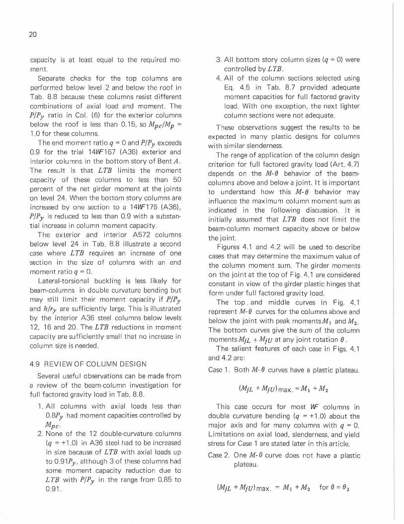
CASE 1 CASE 2 CASE 3
MjL MjL MjL
w > 0
"' <! Z :;; :::J -' 0 u
la) ", " Id) ", " Ig) " , " MjU MjU MjU
~ 0 -' w
"' Z :;; :::J -' 0 u
Ib) 0, " Ie) ", " Ih) ", " MiL + MjU MjL + MjU MjL + MjU
I I I
I I I :;; :::J
'"
I I >-
I z w
I :;;
I I 0
I :;;
I z
I I :;;
I :::J
I -'
I 0
I 2 u
I I I Ie) ", ", " If) ", ", " Ii) ", ", "
FIG.4.1 INFLUENCE OF M· O CUR V ES ON MAXIMUM COLUMN MOMENT SUM
20
capacity is at least equal to the required moment.
Separate checks for the top columns are performed below level 2 and be low the roof in Tab . 8.8 because these columns resist d ifferent combinat ions of axial load and moment. The P/Py ratio in Col. (6) for the exterior columns below the roof is less than 0.15, so Mpc/Mp =
1.0 for t hese columns. The end moment ratio q = 0 and P/Py exceeds
0.9 for the tr ial 14V1F167 (A36) exterior and interior columns in the bottom story of Bent A. The resu lt is that LTB lim its the moment capacity of these columns to less than 50 percent of the net girder moment at the joints on level 24. When the bottom story columns are increased by one section to a 14V1F176 (A361. P/Py is reduced to less than 0.9 with a substantial increase in column moment capacity.
The exterior and interior A572 columns below level 24 in Tab. 8.8 il lustrate a second case where LTB requires an increase of one section in the size of columns with an end moment rat io q = O.
Lateral-torsional buckling is less likely for beam-co lumns in double curvature bending but may st il l limit their moment capacity if P/Py and h/ry are sufficiently large This is illustrated by the interior A36 steel co lumns below levels 12, 16 and 20. The LTB reductions in moment capacity are sufficiently smal l that no increase in column size is needed.
4.9 R EV I EW OF CO LU MN DES IG N
Several useful observations can be made from a review of the beam-column investigation for fu ll f actored gravity load in Tab. 8.8 .
1. All columns w ith axial loads less t han 0.8Py had moment capacit ies contro l led by
Mpc. 2. None of the 12 double-curvature columns
(q = +1.0) in A36 steel had to be increased in size because of LTB with axial loads up to o 91Py , although 3 of t hese columns had some moment capacity reduction due to LTB with P/Py in t he range from 0.85 to 0.91.
3. A ll bottom story co lumn sizes (q = 0) were controlled by LTB.
4. A ll of the column sect ions selected using Eq. 4.5 in Tab. 8.7 provided adequate moment capac ities for full factored gravity load . With one exception, the next lighter column sections were not adequate.
These observations suggest the results to be expected in many plastic designs for columns with si mi lar slenderness.
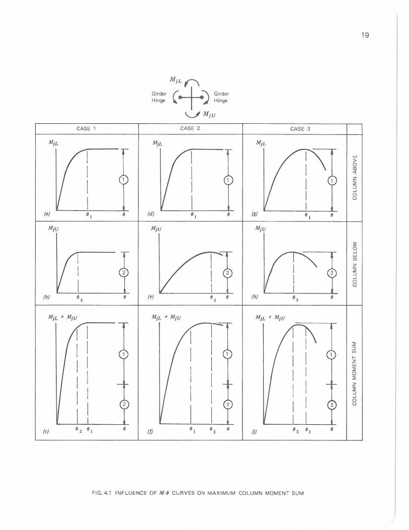
The range of applicat ion of the column design criterion for fu ll factored gravity load (Art. 4.7) depends on the M-8 behavior of the beamco lumns above and below a jo int. It is important to understand how this M-8 behavior may influence the maximum co lumn moment sum as indicated in the following d iscussion. It is initial ly assumed that LTB does not limit the beam-column moment capac ity above or below the joint
Figures 4.1 and 4.2 w il l be used to describe cases that may determine the max imum va lue of the column moment sum. The girder moments on the joint at the top of Fig. 4.1 are considered constant in view of t he girder plasti c hinges that form under full factored gravity load.
The top. and middle curves in Fig. 4.1 represent M-8 curves for the columns above and below the jOint with peak momentsM, andM2 .
The bottom curves give the sum of the co lumn momentsMjL + MjU at any joint rotat ion 8.
The sa l ient features of each case in Figs. 4. 1 and 4.2 are:
Case 1. Both M- 8 curves have a plastic plateau.
This case occurs for most VIF co lumns in double curvatu re bending (q = +1.0) about the major ax is and for many columns with q = O. Limitations on axial load, slenderness, and yield stress for Case 1 are stated later in this article.
Case 2. 0 ne M- 8 curve does not have a plastic plateau.
(MjL + MjU)max = M, + M2 for 8 = 82
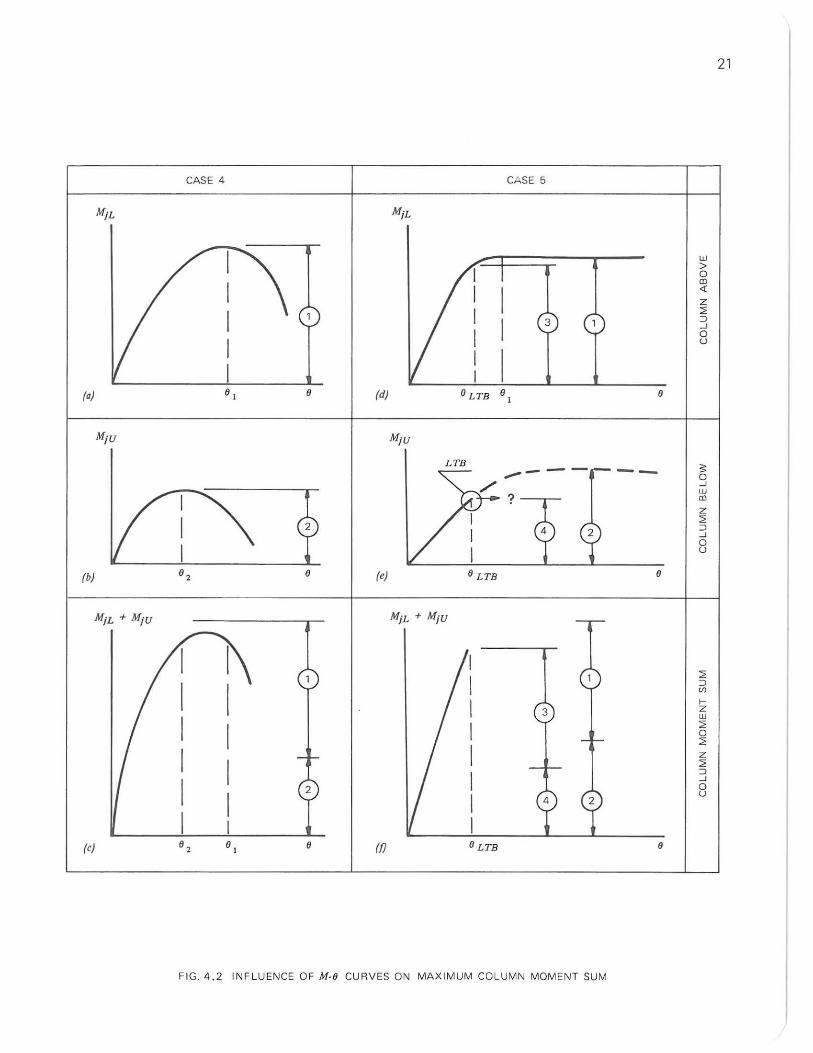
CASE 4 CASE 5
3
(a) 8, 8 (d) (J LTB 8 ,
MjU MjU
LTB
?
(b) 8, 8 (e) (J LTB
MiL + MjU MjL + MjU
3
2
(e) 8, 8 (fJ
FIG.4.2 INFLUENCE OF M·e CURVES ON MAXIMUM CO LUMN MOMENT SUM
--
8
8
w > o CD <1. Z :> :J --' o u
" 0 --' w CD
z :> :J --' 0 u
:> :J
'" >-z w :> 0 :> z :> :J --' 0 u
21
22
This case may occur for slender lower story columns with large ax ial loads and q = 0, for example, in the bottom story. TheM-e curves in Design Aid II for q = 0 serve as a guide to define the qual ifications, slender and large axial load.
Case 3. Both M-e curves have no plast ic plateau but the peak moments occur at nearly equal joint rotat ions.
This case may occur for columns vv ith nearly equal ax ial loads, slenderness, and end moment ratios above and be low the joint if 0 > q > - 1.0 See Design Aid I I.
Case 4. Similar to case 3 but the peak moments occur at substantially different joint rotations.
(MjL+MjUlmax <M,+M2 fore between
e , and e 2
This infrequent case may occur when q .;; 0 and the axial loads, or slenderness, or end moment ratios above and be low the jo int are dissimi lar. The co lumn moment sum at e = e , is a convenient lower bound est imate of (MjL +
MjU) max
Case 5. LTB limits both the moment capacity of one co lumn and the joint rotation.
(MjL+MjU)max. = M3+M4 fore=eLTB
where M4 is the LTB moment for the lower column from Design A id I II, OLTB is the joint rotati on fo r MjU = M4 from Design Aid I I, and M3 is the end moment for the upper column at e = e L TB from Design A id II. This case occurs fo r heavily loaded, laterally unbraced co lumns with q = 0 (for example, bottom story columns with no base restraint) and for columns in single curvatu re, q = - 1. See Design Aid III.
In Case 5, if the jo int rotation exceeds eLTB the column end moment below the joint de-
pends on the post lateral -torsional buckling behavior of the beam-column . This type of beam-column behavior is not well understood at present, wh ich is the reason for the conservative design limitation e .;; eLTB.
These f ive cases do not exhaust all possible combi nations but they do clearly indicate how the shape of the M-e curves governs the maximum column moment sum at a joint. Note that a plastic plateau is desirable but not necessary in plastic design.
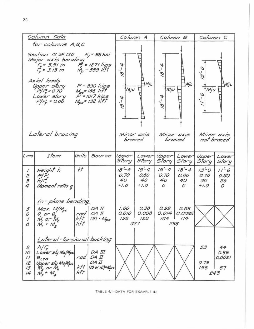
Example 4.1-- This example describes the
combination of M-e curves to determine the maximum column moment sum at a joint. The three columns, designated by A, Band C in Table 4.1, correspond to Cases 1,3 and 5 in Figs 4 .1 and 4.2.
Each column is two stories high and uses the same section, a 121t1F120 in A36 stee l. Each column carries a factored axial load of 890 kips (P/Py = 070) in the upper story and 1017 ki ps (P/Py = 08) in the lower story. The Mpc values for these axial moment diagrams and minor ax is brac ing conditions vary as indicated in Table 4 .1 . The data in this table was selected for ease of reference to the M-e curves in Design Aid II .
The maximum co lu mn moment sum, MjL + MjU , that is availab le to resist the girder moments on the middle floor joint is to be determined. Plastic hinges are assumed at the ends of the gi rders that apply the major axis column moments. The axial load, slenderness, and end moment ratios that det ermine the major ax is in-plane bend ing behavior of the columns are recorded in Lines 2 t o 4 of Table 4.1.
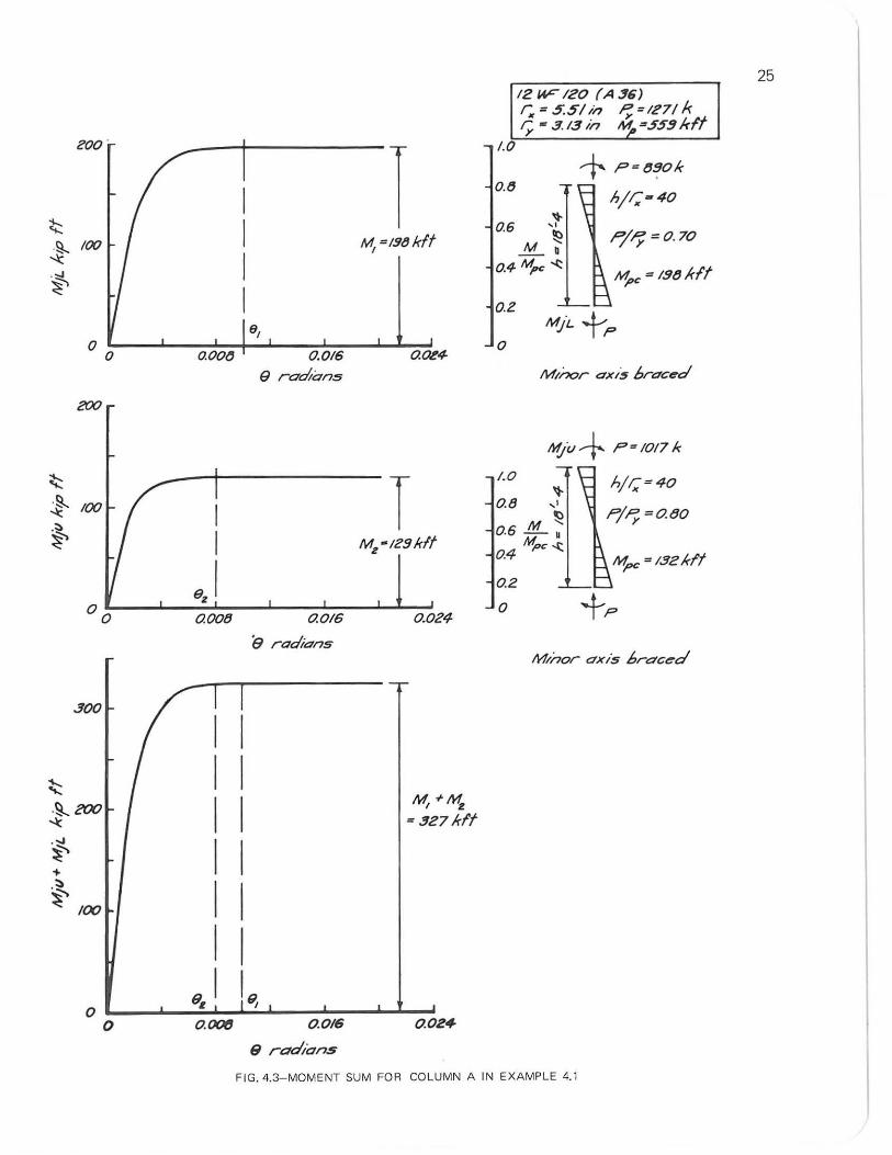
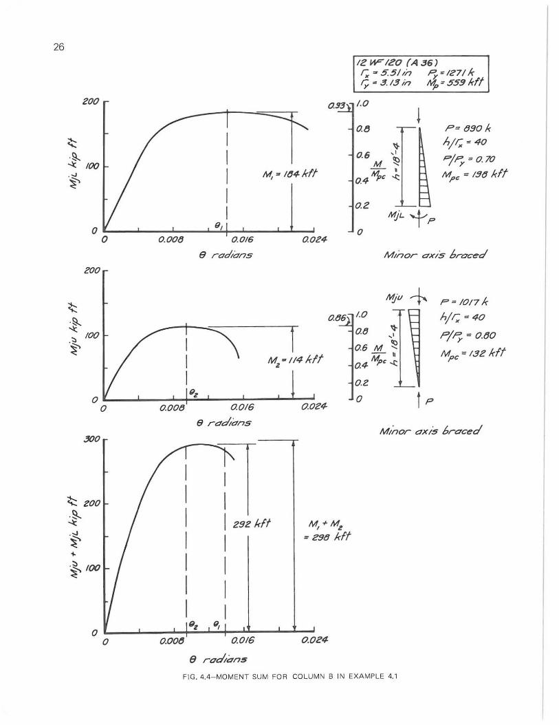
Columns A and 8- These co lumns, with minor axes braced to prevent LTB, reach their maximum moment capacity in the in-plane bending mode. The peaks of the M-e curves in Design Aid I I give the values of max . M/Mpc and end rotation e in L ines 5 and 6 of Table 4.1. The peak moments M, for the upper co lumn and M2 for the lower column in Line 7 are obtained using the Mpc va lues recorded with the axial loads in Table 4. 1. Line 8 gives the monr.entsumM, +M2 .
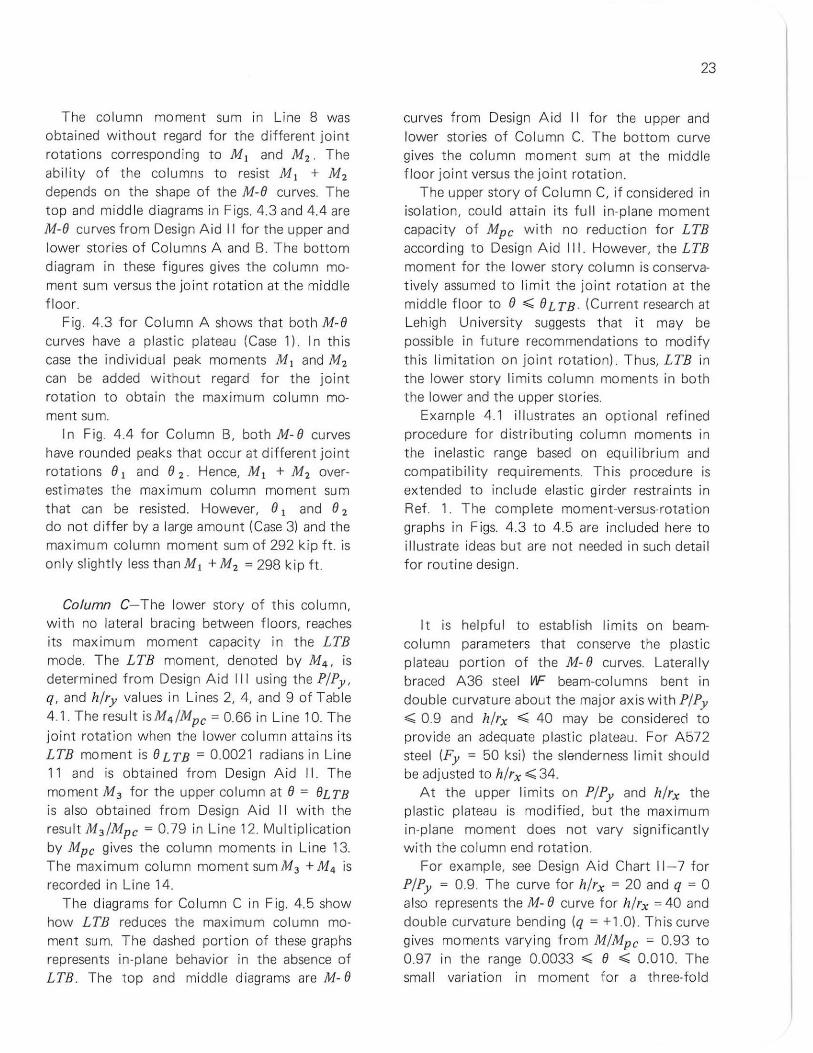
The column moment sum in Line 8 was obtained without regard for the different joint rotations corresponding to M , and M,. The ability of the co lumns t o resist M, + M, depends on the shape of the M-8 curves. The top and midd le diagrams in Figs. 4.3 and 4.4 are M-8 curves from Design Aid II for the upper and lower stories of Columns A and B. The bottom diagram in these figures gives the column moment sum versus the joint rotat ion at the middle floor.
Fig 4.3 for Column A shows that both M-8 curves have a plastic plateau (Case 1) . I n this case the indiv idual peak moments M, and M, can be added without regard for the joint rotation to obtain the maximum column moment sum.
I n Fig. 4.4 for Column B, both M- 8 curves have rounded peaks that occur at different joint rotations 8, and 8 2 . Hence, M, + M, overestimates the maximum column moment sum that can be resisted. However, 8, and 8, do not differ by a large amount (Case 3) and the maximum column moment sum of 292 kip ft. is only slightly less than M, + M, = 298 kip ft.
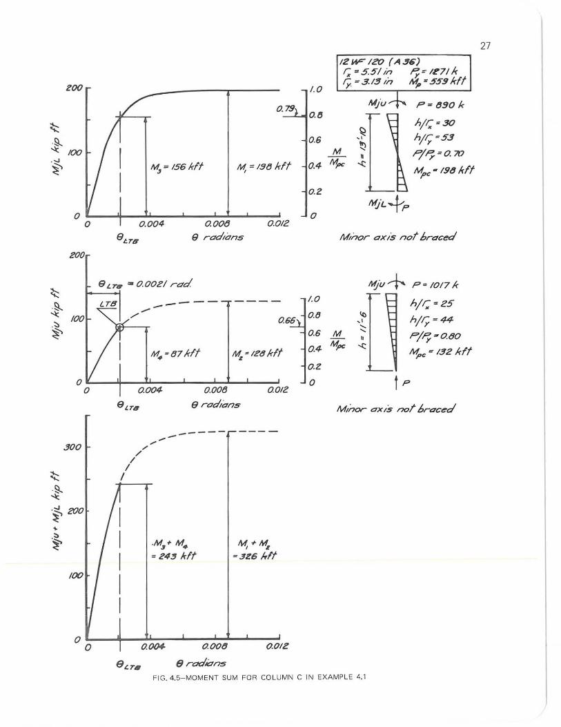
Column C- The lower story of this column, with no lateral bracing between floors, reaches its maximum moment capacity in the LTB mode. The LTB moment, denoted by M4 , is determined from Design Aid III using the P/Py ,
q, and h/ry values in Lines 2, 4, and 9 of Table 4.1. The result is M4/Mpc = 0.66 in Line 10. The joint rotation when t he lower column atta ins its LTB moment is 8 LTB = 0.0021 radians in Line 11 and is obtained from Design Aid I I. The moment M3 for the upper column at 8 = 8LTB is also obtained from Design Aid I I with the result M,/Mpc = 0.79 in Line 12. Multiplication by Mpc gives the co lumn moments in Line 13. The maximum column moment sumM, + M4 is recorded in Line 14.
The diagrams for Column C in Fig. 4.5 show how LTB reduces the maximu m co lumn moment sum. The dashed portion of these graphs represents in -p lane behavior in the absence of LTB. The top and middle d iagrams are M- 8
23
curves from DeSign A id I I fo r the upper and lower stor ies of Column C. The bottom curve gives the co lumn moment sum at the middle floor joint versus the joint rotation.
The upper story of Column C, if considered in isolation, could attain its full in-plane moment capacity of Mpc with no reduction for LTB according to Design A id III. However, the LTB moment for the lower story column is conservatively assumed to limit the jo in t rotation at the middle floor to 8,,;;; 8LTB . (Current research at Lehigh University suggests that it may be possible in future recommendations to modify this limitation on joint rotation). Thus, LTB in the lower story limits column moments in both the lower and the upper stories.
Example 4.1 illustrates an optional refined procedure for distr ibuting column moments in the inelast ic range based on equil ibrium and compatibility requirements. This procedu re is extended to include elastic girder restraints in Ref. 1. The comp lete moment-versus-rotation graphs in Figs. 4.3 to 4.5 are included here to illustrate ideas but are not needed in such detail for routine design.
It is helpful to establi sh limits on beamcolumn parameters t hat conserve the plastic plateau portion of the M- 8 curves. Laterally braced A36 stee l w= beam-columns bent in double curvature about the major axis with P/Py ,,;;; 0.9 and h/rx ,,;;; 40 may be considered to provide an adequate plastic plateau. For A572 steel (Fy = 50 ksi) t he slenderness limit should be adjusted to h/rx ";;;34.
At the upper limits on P/Py and h/rx the plastic plateau is modified, bu t the maximum in-plane moment does not vary significant ly with the column end rotation.
For examp le, see Design Aid Chart 11 - 7 for P/Py = 0.9. The curve for h/rx = 20 and q = 0 also represents the M- 8 curve for h/rx = 40 and double curvature bending (q = +1.0). T his curve gives moments varying from M/Mpc = 0.93 to 0.97 in the range 0.0033 ,,;;; 8 ,,;;; 0.010. The sma l l variation in moment for a three-fold
24
column Dah Column A Column B Column C Tor columns A,B;C
\l ~ Section 12 W-120 Fy = 36 ksi
\~ Major axis t)(!:nci1! r; = 5.51 in y = 1271 k'i?,S "t- "t-ry " 3. 13 in '1> '" 559 kft ,I , 1 ~
~ ~ , I
~A!I'L " ~ AXlo/ loa~ ~~fiL t.{o,oer star!! p", 890 kil?,5 MjU'~
J~i.
?/r;=0.70 Mc=I!J8 kff Mju MjtJ
Lowers/a? P ~/OI7 kf;;s ~ \I)
"t- , 1 PI;y " o. {J, ~c= 132 kIt ,I , 1
" ~ ~ "
~ j t t
Lalera/ bracing MInor axis MInor axis MInor axis braced braced nO/braced
Line Ifel?? Umls Source trer Lower Cf~er Lower ~fo,er Lower Yor!! Star!! or!! Stor!! or!! Star!!
He'J,ht h It 18'-4 1{J'-4 18'-4 18'-4 ,
//'--6 I 13-0 2 P/:,y 0.70 0.80 0.70 0.80 0 . 70 0 .80 3 Z> 40 40 40 40 30 25 4 'Omen/ rolib 'I -1-1.0 -1-1.0 0 0 +1.0 0
In - ,Dkme bendnq: •
5 Max M/~ OAD 1.00 0.98 0 .93 0.{J6 [X [>\ 6 ~ 'Or~ rad OAD 0.010 O.OO{J 0.014 0.0095 7 M, or~ kit (5) x ~c 198 129 184 114 {3 M, + Me kft 327 298
Latera/- torsional buclrlntj
.9 h/ry 53 44 10 Lower slj A4/MfIC DAm 0.66 II 9 LT6 rad DA D 0.002/ 12 '{feer S% M3/tJfoC DAD 0. 79 13 ~ 'Or .., kit flOorlZjxMl'c 156 87 14 ~-I- M.,. kff 243
TABLE 4. I-OATA FOR EXAMPLE 4.1
eoo '
I ~
.t 100 ~=19tJkft
.~ ~
6, 0
0. aoo(J 0.016 o.CM4
() racitans
T °O~--~--~0.~o.~0(J~--~--~o.~.0~~~6--~~~0.~024
9 radians
.300
I I ~ I I .~200 I I
~ .. ~ '4: = 3271rlt .....
I I ~ .. . :) ~ 100 I I
I I 9. 1 I" 0 ~ ,
0 O.ootJ 0.016 0.024
9 radians
12UFI20 (A 36) r" ~ 5.5/ in ;::;127/k r; c 3.13 in ""-"=55!1k1f
1.0
+ P~ (J!lok O.(J
h/t;=40 'I-
0.6 " ~ ?J;:: =0. 70
Mb 0.4 Mpc ~ Mpc ~ I!I(J Irft
0.2 MjL+p
0
MInor aXI5 braced
1.0
~u+ P;1017k
h/t;~40 0.8 ,I
~ 0.6 M ,
~c -l: 0.4
0.2
o
MInor axis brac~d
FIG. 4.3- MOMENT SUM FOR COLUMN A IN EXAMPLE 4.1
25
26 Ie WFIZO (A 36) r; ~ 5.51 In P : 1i?71 Ir t; = 3. 13 in 4:5591r11
200 a~ 1.0
~ o./j p= 890 Ir
~ 'l- h;r; = 40
. ~ 0.6 ,I Plr; = 0.70 -'C 100 M ~ .-J M, : 1t!41rlt NT. • Mpc = 158 IrII ~
0.4 pc oJ:::
02
0 9,
MjL'i-' p
a 0 0.006 0.016 0.024
e radtcms MInor aXIS 6roc~d 200
~ Mjll -f.. P = 1017 if
.~ 0.86 1.0 hjr; = 40. -'C
1 0.8 'l- Plr; = MO .~ 100 ,I
'I:l ~ 0.6 M ....
Mpc = 13Z Irll M2~1141r1t
- h
0.4 ~c oJ:::
0.2
0 Bz 0 t P
0 0.008 0.016 o.OZ4
e rodans MInor aXIS 6rac~d
300
252 kit M,+Mz = i?96 Ht
o L-__ ~ __ ~~~~~~--~~ o O.GOt! 0.016 o.Oe4
e radtans
FIG. 4.4-MOMENT SUM FOR COLUMN B IN EXAMPLE 4.1
zoo
0..79
~=156kff M = 1.98 kft ,
o L...._+_..I.L-_ ....... _-JI-.I._ ...... _ .... o 0.004 0.008 O.OIZ
zoo
30.0.
100
9 racitans
9 LT" '" o..Oo.ZI rad
LTB
/
-----...... /'
0.66
M .. = 871<It ~'lz8kft
0.004 0..008 o.o.lZ
9 radti:ms
,,_------r---- -/
/ /
/
o. L-_~_~_~_-JL~_ ...... _ .... o 0.()(H o.ool! o.o.lZ
8 radians
1.0
o..tJ
0..6
0.4
0..2
0.
1.0.
O.tJ
0.6
0.4
0..2
0
IZ/AFlZO (A~6) r;=55Iin ry=lr7lx r; <1./3 In M,. ~ 55.9lrft
Mju -f.. p = 8!1o. k
hjl; =.30
hjr;=53
P/P,=0.70
M,..c - 1.98 kit
MInor aXIS not braced
~u-f.. p·10.17k
hjr;=25 «) hit; = 44 -' "-
M "-P/ry=o.80.
Mpc --t ~c= 132 kIt
t p
MInor ax IS not brac~d
FIG. 4.5-MOME NT SUM FOR CO LUMN C IN EXAMPLE 4.1
27
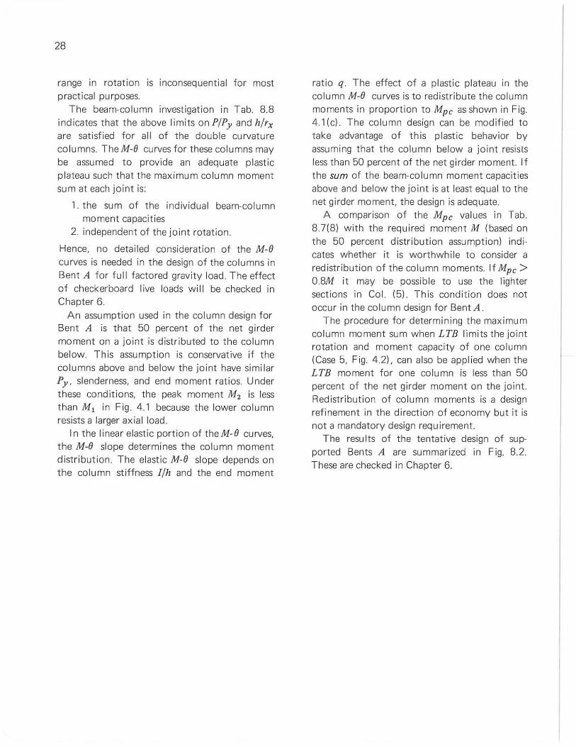
28
range in rotation is inconsequentia l for most practical purposes.
The beam-co lu mn investigation in Tab. 8.8 indicates that the above l imits on P/Py and h/rx are sati sfied for all of the double curvature co lumns. TheM-8 curves for these co lumns may be assumed to provide an adequate plastic plateau such that the maximum co lumn moment sum at each join t is:
1. the sum of the ind ividual beam-column moment capacities
2. independent of t he jOin t rotation.
Hence, no detailed consideration of the M-O curves is needed in the design of the co lumns in Bent A for full factored gravity load. T he effect of checkerboard live loads will be checked in Chapter 6.
An assumption used in t he col umn design for Bent A is that 50 percent of the net girder moment on a joint is distributed to the co lumn below. This assumption is conservat ive if the co lumns above and below the jO int have simi lar Py , slenderness, and end moment ratios. Under these cond iti ons, the peak moment M2 is less than Ml in Fig . 4.1 because the lower co lumn resists a larger axial load.
In t he linear elasti c portion of t heM-O curves, the M-O slope determines the co lumn moment distr ibution. The elast ic M-O slope depends on the co lumn st iffness l /h and the end moment
ratio q. The effect of a plast ic plateau in the column M-O curves is to redistribute the column moments in proportion to Mpc as shown in Fig. 4.1 (c) . The co lumn design can be modi f ied to take advantage of t his plastic behavior by assuming that the column below a joint resists less than 50 percent of the net girder moment. If the sum of t he beam-co lumn moment capacities above and below the joint is at least equa l to the net girder moment, t he design is adeq uate.
A comparison of the Mpc va lues in Tab. 87(8) w ith the req uired moment M (based on the 50 percent distribution assumption) indicates whether it is worthwhile t o consider a redistribution of the column moments. If Mpc > 0.8M it may be possible to use the lighter sections in Col. (5). This condit ion does not occur in t he co lumn design for Bent A.
The procedure for determining the max imum co lumn moment sum when LTB limits the joint rotation and moment capaci ty of one column (Case 5, Fig. 4.2), can also be appl ied when the LTB moment for one column is less than 50 percent of the net girder moment on t he joint. Redistr ibution of column moments is a design refinement in the direction of economy but it is not a mandatory design requirement.
The resu lts of the tentat ive design of supported Bents A are summarized in Fig. 8.2. These are checked in Chapter 6.
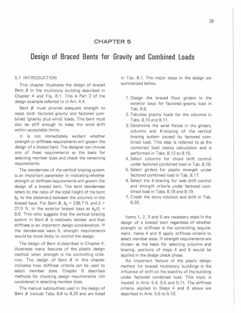
29
CHAPTER 5
Design of Braced Bents for Gravity and Combined Loads
5.1 INTRODUCTION
T his chapter i llustrates the design of braced Bent B in the multistory building described in Chapter 4 and Fig. 8. 1. Th is is Part 2 of t he design example referred to in Art. 4.4.
Bent B must provide adequate strength to resist both factored gravity and factored combined (grav ity plus wind) loads. This bent must also be st if f enough to keep the wind drift with in acceptable limits.
It is not immed iately evident whether strength or stiffness requ irements will govern the design of a braced bent. The designer can choose one of these requi rements as the basis for se lecting member sizes and check t he remaining requi rements.
The slenderness of t he vertica l brac ing system is an important parameter in indicating whether strength or stiffness requirements wi ll govern the design of a braced bent. The term slenderness refers to the ratio of the tota l height of the bent ht to the distanceL between the co lumns in t he braced bays. For 8ent B, ht = 236.7 ft. and L =
27.0 ft. in the exterior braced bays so htlL =
8.8. This rat io suggests that the vertica l bracing system in Bent B is relatively slender and that stiffness is an important design consideration. If the slenderness were 5, strength requ irements wou ld be more likely to contro l the design.
The design of Bent A,described in Chapter 4, i llustrates many features of the plastic design method when strength is the contro lli ng criterion. The design of Bent B in this chapter indicates how st iffness criteria can be used to select member sizes. Chapter 6 describes methods for checking design requirements not considered in selecting member sizes.
The manual subroutines used in the deSign of Bent B include Tabs. 8.9 to 8.20 and are listed
in Tab. 8.1. The major steps in the design are summarized below.
1. Design the braced f loor gi rders in t he exterior bays for factored gravity load in Tab. 8.9.
2. Tabulate gravity loads for the columns in Tabs. 8.10 and 8.1 1.
3. Determine the ax ial forces in the girders, columns and K-bracing of the vertica l bracing system caused by factored combined load . This step is referred to as the combined load stat ics ca lculat ion and is performed in Tabs. 8.12 to 8.15.
4. Select columns fo r chord drift contro l under factored comb ined load in Tab. 8. 16.
5. Se lect girders for plast ic strength under factored combined load in Tab. 8.17.
6. Select the K-bracing for web drift control and strength criteria under factored combined load in Tabs. 8.18 and 8.19.
7. Check the story rotation and drift in Tab. 8.20.
Items 1, 2, 3 and 5 are necessary steps in the design of a braced bent regardless of whether strength or stiffness is the control ling requirement. Items 4 and 6 apply st iffness criteria to select member sizes. If strength requ irements are chosen as the basis for se lecting columns and bracing, portions of steps 4 and 6 would be applied in the design check phase.
An important feature of the plastic design method for braced multistory bui ldings is the influence of drif t on the stability of the building under factored combined load. This topic is treated in Arts. 5.4, 5.5 and 5.11. The stiffness cr ite ri a applied in Steps 4 and 6 above are described in Arts. 5.6 to 5.10.
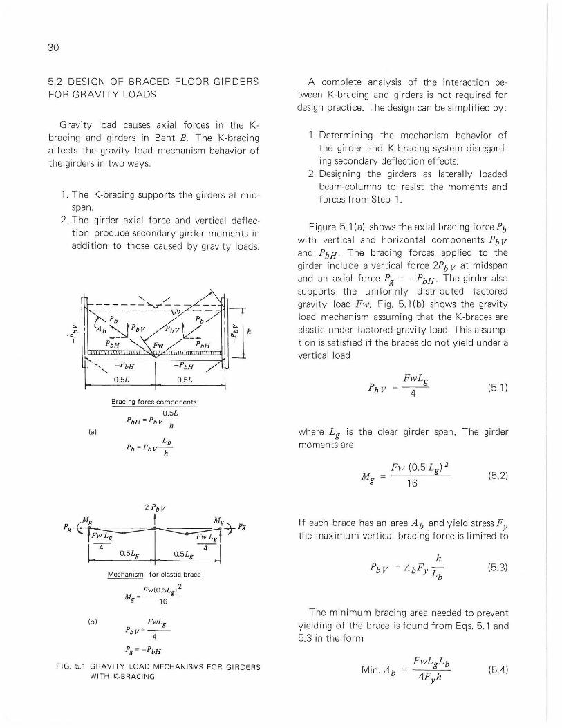
30
5,2 DESIGN OF BRACED FLOOR GIRDERS FOR GRAVITY LOADS
Gravity load causes ax ial forces in the Kbracing and girders in Bent B, The K-bracing affects the gravity load mechanism behavior of the girders in two ways:
1, The K-bracing supports the girders at midspan,
2, The girder axial force and vert ica l deflection produce secondary girder moments in addition to those caused by gravity loads,
lal
IbJ
0,5L
- PbH
0,5L
Bracing force components
0 ,5L PbH=PbV -
h
O.5Lg
Mechanism- for elastic brace
2 FwIO.5Lg l Mg - 16
FwLg PbV "" --
4
Pg = - PbH
/ ,/
FIG. 5,1 GRAVITY LOAO MECHAN ISMS FOR GIRDERS WITH K-BRACING
A complete analysis of the interaction between K-bracing and girders is not required fo r design practice, The design can be simplif ied by
1. Determ ining the mechan ism behavior of the girder and K-braci ng system disregardi ng secondary def lection effects,
2, Design ing the girders as latera lly loaded beam-columns to resist the moments and forces from Step 1,
Figu re 5,1 (a) shows the axial bracing force Pb with vertica l and horizontal components Pb V
and PbH . The bracing forces applied to the girder include a vertical force 2Pb V at midspan and an axial force Pg = - PbH , The girder also supports the uniformly d istr ibuted factored gravity load Fw, Fig, 5,1 (b) shows the gravity load mechanism assuming that the K-braces are elast ic under facto red gravity load, This assumption is satisfied if the braces do not yield under a vertical load
FwLg =--
4 (51)
where Lg is the clear gi rder span, The girder moments are
(52)
If each brace has an area Ab and yield stress Fy the maximum vert ical bracing force is limited to
(53)
The minimum bracing area needed to prevent yielding of the brace is found from Eqs, 5.1 and 5,3 in the form
(5.4)
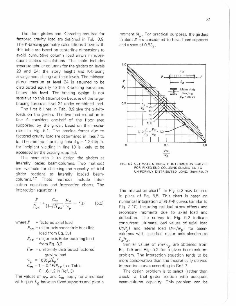
The floor girders and K-bracing required for facto red gravity load are designed in Tab. 8.9. The K-bracing geometry calcu lat ions shown with this table are based on centerline dimensions to avoid cumulative column load errors in subsequent statics ca lculations. The table inc ludes separate tabu lar columns for the girders on levels 23 and 24; the story heigh t and K-bracing arrangement change at these levels. The midspan girder reaction at level 24 is assu med to be distributed equally to the K-bracing above and below this leve l. The brac ing design is not sensit ive to this assumpt ion because of the larger bracing forces at level 24 under comb ined load.
The f irst 6 lines in Tab. 8.9 give the gravity loads on the girders. The l ive load reduction in line 4 considers one-ha lf of the f loor area supported by the gi rder, based on the mechanism in Fig. 5.1 . The brac ing forces due to factored gravity load are determined in lines 7 t o 9. The minimum bracing area Ab = 1.34 sq.in. for incipient yielding in line 10 is likely to be exceeded by the bracing supplied.
The next step is to design t he girders as laterally loaded beam-columns: Two methods are available for check ing the capacity of trial girder sections as laterally loaded beamco lumns},7 These methods include interaction equat ions and interaction charts. The interaction equation is
where P = factored axia l load Pox = major axis concentric buck ling
load from Eq. 3.4 Pex = major axis Eu ler buckling load
from Eq. 3.9 F w = un iformly d istr ibuted factored
gravity load
wp = 16Mp/i/ Cm = 1 - O.4P/Pex (see Tab le
C 1.6.1.2 in Ref . 3)
(5.5)
The values of wp and Cm apply f or a member with span Lg between fix ed supports and plastic
31
moment Mp . For practical purposes, the girders in Bent B are considered to have fixed supports and a span of 0.5Lg .
Fw
P I----t<~~ P _~! ! II!!! II I [l-p·
f-- Lg ------l Py ~-+-~~'" _T_ Major Axis
• Bending Fy =36ksi
0.5f--+--
P Fw 1.10-+-=1 .0
Py wp +-_I--+_-I-~~
o 0.5
Fw wp
1.0
FIG. 5.2 ULTIMATE STRENGTH INTERACTION CURVES FOR FIXED-EN D COLUMNS SUBJECTED TO UNIFORMLY DISTRIBUTED LOAD. (from Ref . 71
The interaction chart 7 in Fig. 5.2 may be used in place of Eq. 5.5. This chart is based on numerical integration of M-P-tP curves (similar to Fig. 3.10) includ ing residual st ress effects and secondary moments due to ax ial load and deflection. The curves in Fig. 5.2 indicate concurrent ultimate load values of axial load (P/Py ) and latera l load (Fw/wp) f or beamco lu mns with specified major ax is slenderness
Lg/rx Similar values of Fw/wp are obtained f rom
Eq. 5.5 and Fig. 5.2 fo r a given beam-column problem. The interaction equation tends to be more conservat ive than the theoretically derived interaction curves according to Ref. 7.
T he design problem is to select (rather than check) a tr ia l gi rder section with adequate beam-column capacity. This problem can be
32
simplified for A36 steel beam-columns with Lg/rx';; 40 or for Fy = 50ksi with Lg/rx';; 34. In th is slenderness range, the coefficient of Fw/wp
in Eq. 5.5 can be taken as unity and Pox/Py =
0.91 from Eq. 3.5. These substitutions reduce Eq. 5.5 to the linear form
P Fw 1.10 - + - = 1.0 (5.6)
Py wp
This formula closely approximates Eq. 5.5 for A36 steel with Lg/r x = 40 and is represented by the dashed line in Fig. 5.2.
The terms Fw and wp are conveniently converted to moments by the equations
and,
FwLg2 Mg = ---:-,,"--
16 (5.7)
(5.8)
Then Eq. 5.6 can be rearranged to
(5.9)
Using Eqs. 4.7 and 4.8 to approximate MpPy for VIF shapes bent about the major axis gives the design equation
Mp = Mg + 0.46Pd (5.10)
where Mp = required plastic moment capacity for the latera lly loaded beam-column, kip-ft.
Mg = plastic moment for a mechanism in the absence of ax ial load per Eq. 5.7, kip-ft.
P = factored axial load, kips d = estimated depth, ft.
The second term in Eq. 5.10 represents a "moment equivalent" for the axial load that depends on the estimated depth d. If the estimate for d is appropriate, a VIF section with plastic moment Mp and depth d can be selected from a plastic section modulus table. The section will satisfy Eq. 5.5 if Lg/rx .;; 40 for A36 steel beam-columns with fixed ends, so no check is needed. If Lg/rx exceeds this bound, it is advisable to select a trial section with Mp somewhat larger than the value from Eq . 5.10 and to check the trial section using Eq. 5.5. Some decrease in Mp for the trial section below the va lue given by Eq. 5.10 can be accepted for decreasing values of Lg/rx.
Equation 5.10 is applied in Lines 11 to 15 of Tab. 8.9 to select girders for the K-braced bays in Bent B. The moment Mg in line 11 is based on the span 0.5 Lg for the mechanism in Fig. 5.1. The major axis slenderness in Line 18 is less than 40 so no further beam-column check is needed. The web d/w in Line 19 is less than 43; hence, the trial A36 lOB 19 section is adequate for web buckling under axial load. A 12B 16.5 might also be selected to provide Mp = 62.7 kip-ft. from Eq . 5.10 with d = 1.0 ft. However, the web of this section is not adequate for web buck l ing under ax ial load according to Table 3.3. Web buckling shou Id be investigated for A36 shapes with d/w > 43 that must resist axia l load.
5.3 COLUMN GRAVITY LOADS
The K-bracing in Bent B mod ifies the tributary areas for the columns as shown in Fig. 5.3. This figure indicates the portions of full floor and roof loads that produce ax ial load in selected columns. Figures 5.3{a) and (b) show that the columns below the roof must resist floor loads from one quarter of the exterior bay on Level 2. The floor areas that are the source of the column load increment below Level 2 are shown in Figs. 5.3{c) and (d). The increment of column live load from the f loors is the same in
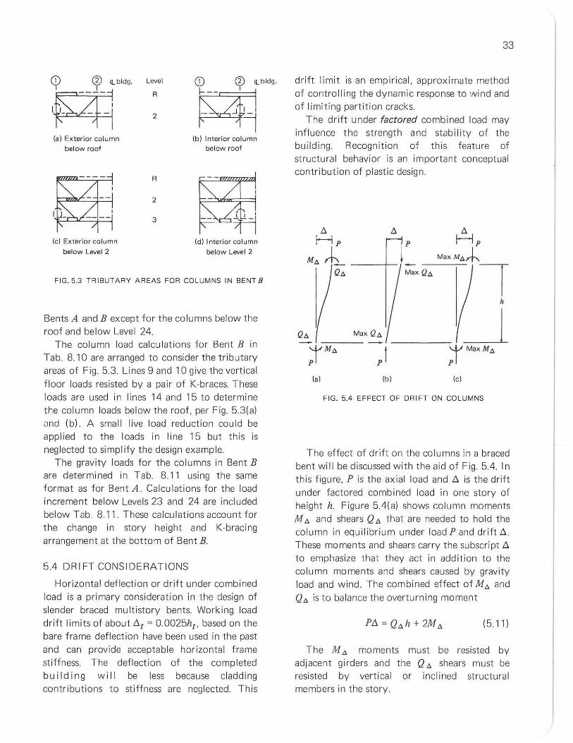
G) G) <Lbldg.
~ 1F=t4 (a) Exterior column
below roof
(e) Exterior column
below Level 2
Level
R
2
R
2
3
~<Lbld9.
~4 (b) Interior column
below roof
(dl Interior column
below level 2
FIG.5.3 TRIBUTARY AREAS FOR COLUMNS IN BENT B
Bents A and B except fo r the columns below the roof and be low Level 24.
The column load calculations for Bent B in Tab. 8.10 are arranged to consider t he t ributary areas of Fig. 5.3. Lines 9 and 10 give the vertical f loor loads resisted by a pair of K-braces. These loads are used in lines 14 and 15 to determine the column loads below the roof, per Fig. 53{a) and (bl. A small live load reduct ion could be applied to the loads in li ne 15 but this is neg lected to simpl ify the design example.
The gravity loads for the columns in Bent B are determined in Tab. 8.1 1 using the same format as for Bent A . Calculations for the load increment below Leve ls 23 and 24 are included below Tab. 8. 11. These calculat ions account for the change in story height and K-bracing arrangement at the bottom of Bent B.
5.4 DRIFT CONSIDERATIONS
Horizontal deflection or dr ift under combined load is a primary consideration in the design of slender braced multistory bents. Working load drift l imits of about t:.t = 0.0025ht , based on the bare frame deflect ion have been used in the past and can provide acceptable horizontal frame stiffness. The deflection of the completed bu il ding will be less because cladding contribut ions t o st iffness are neglected. This
33
drift limit is an empirical, approximate method of controlling the dynamic response to wind and of limiting partition cracks.
T he drift under factored combined load may influence the strength and stability of the build ing. Recognition of this feature of st ructura l behavior is an important conceptual contribution of plastic design.
Max Qa
Max Q.a.
j'MaXM,6,
Ibl lei
FIG. 5.4 EFFECT OF DRIFT ON COLUMNS
The effect of drift on the columns in a braced bent will be discussed with the aid of Fig. 5.4. In this figure, P is the axial load and t:. is the dr ift under factored comb ined load in one story of height h. Figure 5.4{a) shows column moments M", and shears Q '" that are needed to hold the column in equi l ibr ium under load P and drift t:.. These moments and shears carry the subscript t:. to emphasize that they act in add ition to the column moments and shears caused by gravity load and w ind. The combined effect of M" and Q", is to ba lance the overturning moment
(5 11)
The M", moments must be resisted by adjacent girders and the Q '" shears must be resisted by vertica l or inclined structural members in the story.
34
The portions of PI::. resisted by Q", and M", may vary. However it is possible t o establ ish useful bounds, Max Q", and Max M "', on these shears and moments by assuming that on ly one of them is active as in Fig. 5.4( b) and (c).
Alternate paths fo r resisting the PI::. moment are provided by
and,
Max. Q", = P~ h
1 Max. M", = 2" PI::.
(512)
(513)
At t his po int, it is helpful to describe a major d ifference between a braced and an unbraced bui ld ing.
I n a braced bu i Idi ng, the floor slab and the bracing in vertica l planes provide an effective path for resisting shear in each story of each bent. This is true both f or the shear due to wind and for t he Q", shears caused by the PI::. moments. Hence the Q ",It term in Eq. 5. 11 tends to balance most of the PI::. moment. To simp li fy the design of braced buildings, it is conservatively assumed that al l of the PI::. moments are balanced by Q", shears per Fig. 5.4(b) and Eq. 5.12. These Q", shears are transmitted to t he braced bents by the f loor slab and resisted by the vert ica l brac ing system.
In an unbraced build ing, al l resistance to shear is considered to be prov ided by bending of the columns and girders. T he sum of the column shears in a story equals the wi nd shear; there are no other structural members available to resist shear. If t he PI::. moment in one col umn is balanced by a shear Max. Q", as in Fig. 5.4(b), the rema ining co lumns must resist this Max. Q '"
in addition to their own PI::. moments. Hence, the M '" term in Eq. 5.11 functions alone in ba lancing the PI::. moments. This is the conditi on considered in Fig 5.4(c) and Eq. 5.13.
I n summary, the PI::. moments in the columns of a braced build ing are considered to be balanced by Q", shears in t he vertica l bracing system. The PI::. moments in an unbraced build ing are balanced by column and girder moments.
The combined load stat ics ca lculations for Bent B , described in Art. 55, use Eq. 5. 12 to estimate the PI::. shear in each story. The story drift under factored comb ined load is not known when the design commences so it is necessary to estimate a va lue for the drift index I::. /h. If the acceptable worki ng load drift index of 0.0025 is f actored by 1.3 and allowance is made f or add itional drift due to PI::. effects, the drift index under factored combined load is assumed to be 0.004. The design example based on a drift index of 0.004 at factored load will be shown to have a dr ift index cl ose to 0.0025 at working load.
5.5 COMB INED LOAD STAT ICS CALCULATIONS
T he next design step is to determine the axial forces in the vertical bracing system including the girders, columns and K-bracing in Bent B under factored combined load. To simplify t his step, Bent B is considered to consist of two pin-connected, verti ca l, cant i lever t russes, which are pin-connected by the girders in the interior bay. More refined structu ral assumptions, such as incl ud ing the effects of interior girder restraints, may be advan tageous but are not appl ied here in the interest of brevity. Each truss is assumed to resist one-half of t he tota l shear in each story from t hree Bents A and one Bent B.
The horizontal shears resisted by Bent Bare determined in Tab. 8.12. Co ls. (1) and (2) give the wind forces and wind shears at worki ng load (F = 1.0) from the 96 ft. length of the bui ld ing braced by Bent B (see Floor Framing Plan in Fig. 8.1l. The combined load factor F = 1.3 is applied in Col. (3) to fin d the factored wind shears 'LH be low each level. The brac ing system in Bent B must also resist the PI::. shears (Eq. 5.12) from th ree Bents A and one Bent B. The PI::. shears are proportional to the total factored
gravity loads "L-P on these four bents. Cols. (6) and (7) list "L-P and the P!l shears be low each level. The P!l shears are based on an assumed dr ift index !l /h = 0.004 in every story. (See Art. 5.4 and 5.11) Tab. 8. 12(8) gives the total factored shears due to wind plusP!l .
PH = "L-H + 0.004"L-P (514)
These are the shears to be resisted below each level of Bent B.
The axial forces in the girders and columns of Bent B under factored combined load are determined in Tab. 8.13. Col. (1) gives the total shear PH below each level from the preceding table. Most of the horizontal forces resisted by the vertical bracing system in Bent Bare transmitted to this bent through the floor slab. To simplify the statics ca lculations it is assumed that the horizontal forces are appl ied to the pin·connected trusses at the midspan K·brace joints in the braced bays. The horizonta l component of the K·brace force due to wind plus P!l is recorded in Col. (2) Each K·brace resists one·fourth of PH' Gravity load on the girders also causes bracing forces with horizontal components in Col. (3). The forces in Col. (3) are obtained from the grav ity load analysis in Tab. 8.9(8) with a load factor adjustment. The axial girder loads Pg in Tab. 8. 13(4) are the sum of the horizontal bracing forces due to gravity and wind plus P!l .
Wind load causes equal and opposite vertical fo rce components in each pair of K·braces. Hence, the gi rders do not resist any vert ical force from the K·bracing due to wind. This assumes that t he K·bracing does not yield in tensi on or buck Ie in compression under factored combined load.
The vertica l component of the K·brace force due to wind plus P!l below each level is listed in Tab. 8.13(6) The vert ical components are summed from the roof down in Tab. 8. 13(7) to give the axia l loads in the columns (truss chord forces) due to wind plus P!l. These co lumn loads cause tension in windward chords and compression in leeward chords of the two
35
cant ilever t russes in Bent B. The compression in the leeward chords is added to the factored co lumn gravity loads f rom Tab. 8.11 to deter· mine the total compressive column loads under factored combined load in Tab. 8.13(8) and (9).
The calculations in Tab. 8.14 provide a check on the axial column loads in Bent B caused by wind plus P!l. The fi rst three steps determine the uniformly distributed hor izonta l load
(5 15)
resisted by the two canti lever trusses. To ap· proximate t he overturning moment due to P!l an equivalent horizonta l load w" is added to t he factored wi nd load Fww , where
=--- (516) h h
The term "L- OP is the total factored gravity load increment applied at each level including column live load reductions. With !l/h = 0.004, Eq 5.16 gives w" = 0.36 kips per ft., wh ich is 14.4 percent of the factored wind load Fww = 2.50 kips per ft . in Tab. 8.14. Th is is a measure of the influence of estimated P!l effects in this design example. The portion of the story shear caused by P!l is a sign ificant but not a dominant contribu t ion.
Steps 4 to 6 in Tab. 8.14 show calculat ions for the cantilever forces and moments at Level 24. The hor izontal shear checks with the va lue in Tab. 813(8) be low Level. 24 and the ax ial column loads are in reasonable agreement with the values obtained from summing the vertica l bracing force components in Tab. 8. 13(7). The K·brace slope ratio h10.5L in Tab. 8.13(5) is a factor in the column load calculat ions. Th is rat io shou ld be based on center l ine dimensions of the braced bay to avoid cumu lative errors in the column loads. This is verified by t he check in Step 6 of Tab. 8.14.
The axial forces in the K·bracing under factored combined load are determined in Tab. 8.15. The axial forces due t o wind plus P!l in
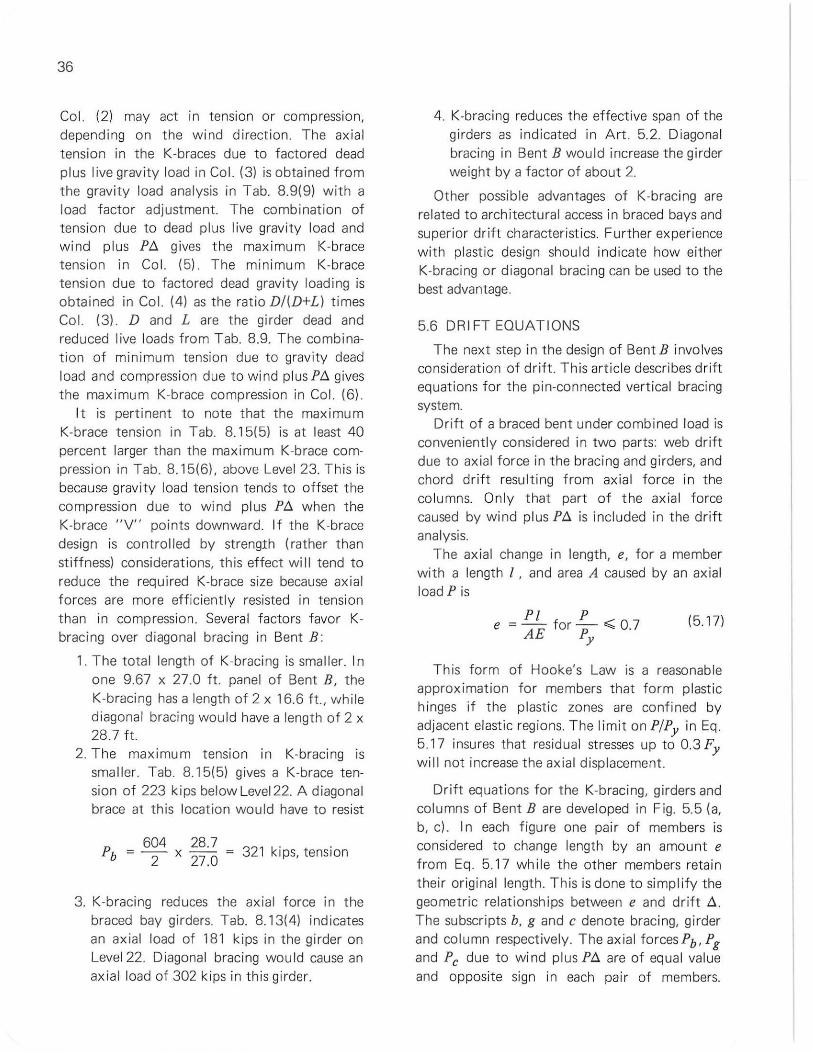
36
Col. (2) may act in tension or compress ion, depending on the w ind direction. The axial tension in the K-braces due to factored dead plus live grav ity load in Col. (3) is obtained from the gravity load analysis in Tab. 8.9(9) with a load factor adjustment. The combination of tens ion due to dead plus live gravity load and wind plus Ptl gives the maximum K-brace tension in Col. (5). The minimum K-brace tension due to factored dead gravity loading is obtained in Col. (4) as the ratio D/(D+L) times Col. (3). D and L are the girder dead and reduced live loads from Tab. 8.9. The combination of minimum tension due to gravity dead load and compression due to wind plusPtl gives the maximum K-brace compression in Col. (6).
It is pertinent to note that the maximum K-brace tension in Tab. 8.15(5) is at least 40 percent larger than the maximum K-brace compression in Tab. 8.15(6). above Level 23. T his is because gravity load tension tends to offset the compression due to wind plus Ptl when the K-brace "V" points downward. If the K-brace design is contro lled by strength (rather than st iffness) considerations, this effect wi II tend to reduce the required K-brace size because axial forces are more efficiently resisted in tension than in compression. Severa l factors favor Kbracing over diagonal bracing in Bent B:
1. The total length of K-bracing is smaller. In one 9.67 x 27.0 ft. panel of Bent B, the K-bracing has a length of 2 x 16.6 f t ., wh ile diagonal bracing would have a length of 2 x 28.7 ft.
2. The maximum tension in K-bracing is sma l ler. Tab. 8.15(5) gives a K-brace tension of 223 kips below Level 22. A diagonal brace at this location would have to resist
P 604 28.7 32' . b ; --:2 x 27.0; 1 kiPS, tension
3. K-bracing reduces the axial force in the braced bay girders. Tab. 8.13(4) indicates an axial load of 181 kips in the girder on Level 22. Diagonal bracing would cause an axial load of 302 kips in t his girder.
4. K-bracing reduces the effective span of the girders as indicated in Art. 5.2. Diagonal bracing in Bent B would increase the girder weight by a factor of about 2.
Other possible advantages of K-bracing are related to architectural access in braced bays and superior drift characteristics. Further experience with plastic design should indicate how either K-bracing or diagonal bracing can be used to the best advantage.
5.6 DRIFT EQUAT IONS
The next step in the design of Bent B involves consideration of dri ft. Th is article describes drift equat ions for the pin-connect ed vertical bracing system.
Drift of a braced bent under combined load is conveniently considered in two parts: web drift due to axial force in the bracing and girders, and chord drift resulting from axia l force in the co lumns. Only that part of the axia l force caused by wind plus Ptl is included in the drift analysis.
The ax ial change in length, e, for a member with a length I , and area A caused by an axial load Pis
PI P e ; -- for - .;; 0 7 AE P . y
(517)
This form of Hooke's Law is a reasonable approximation for members that form plast ic hinges if the plastic zones are confined by adjacent elastic regions. The I imit on PIPy in Eq. 5.17 insures that residual stresses up to 0.3 Fy will not increase the axial displacement.
Dr ift equations for the K-bracing, girders and columns of Bent B are developed in Fig. 5.5 (a, b, c) . I n each figu re one pair of members is considered to change length by an amou nt e from Eq. 5.17 while the other members retain their original length. This is done to simp lify the geometric relationships between e and drift tl. The subscripts b, g and c denote bracing, girder and column respectively. The axial forcesPb, Pg and Pc due to wi nd plus Ptl are of equal value and opposite sign in each pair of members.
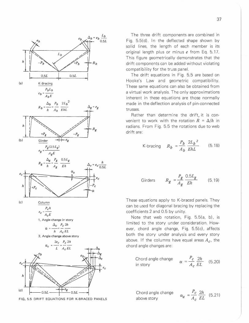
la)
Ie)
h
O.5L O.5L
K·8racing
Column
Pch e = -
C AcE
,. Angle change in story
t1c Pc 2h a = - =--
" Ac EL 2. Angle change above story
2ee Pc 2h a a _ = __
C L Ac EL
Id ) O.5L eg O.5L---j
FIG. 5.5 DRIFT EQUATIONS FOR K·B RACED PANE LS
37
The three drift components are combi ned in Fig. 5.5(d). In the deflected shape shown by solid lines, the length of each member is its original length plus or minus e from Eq . 5.17. This figure geometrical ly demonstrates that the drift components can be added without violating compatibility for the truss panel.
The drift equations in Fig 5.5 are based on Hooke's Law and geometric compatibility. These same equations can also be obtained from a virtual work analysis. The on ly approximations inherent in t hese equations are those norma lly made in the deflection analysis of pin-connected trusses.
Rather than determine the drift, it is convenient to work with t he rotation R ; D./h in rad ians. From Fig. 5.5 the rotations due to web drift are:
K-brac ing Pb 2Lb 2
;---
Ab EhL (518)
Girders Pg 0.5Lg
; ---
Ag Eh (519)
These equations apply t o K-braced panels. They can be used for diagonal bracing by rep lacing the coeff icients 2 and 0.5 by unity
Not e that web rotation, Fig 55(a, b), is li mited to the story under consideration. However, chord angle change, Fig 55(c1. affects both t he story under analysis and every story above. If the columns have equal areas A c, the chord ang le changes are:
Chord ang le change in story
Chord angle change above story
Pc 2h (){ ; --
Ac EL (520)
Pc 2h (){a ; - -- (5.211
Ac EL
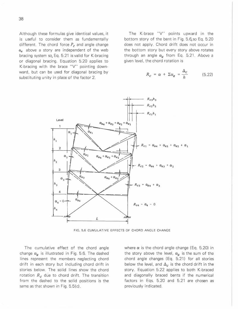
38
Although t hese formulas give identical values, it is useful to consider them as fundamentally d ifferent . The chord force Pc and angle change aa above a story are independent of the web bracing system so, Eq 5.21 is valid for K-bracing or diagonal bracing. Equation 5.20 applies to K-bracing with the brace "V" pointing downward, but can be used for diagonal bracing by substituting unity in place of the facto r 2.
Level
"', h,
2
"', h,
3
a, h,
4
0:4
'" 0 aa4
h4
L
The K-brace "V" points upward in the bottom story of the bent in Fig. 5.6,so Eq. 5.20 does not apply. Chord drift does not occur in the bottom story but every story above rotates through an angle Cia from Eq. 5.21. Above a given level, the chord rotation is
flc
h (522)
FIG. 5.6 CUMULATIVE EFFECTS OF CHORD ANGLE CHANGE
The cumu lative effect of the chord angle change Cia is illustrated in F ig 5.6. The dashed lines represent the members neglecting chord drift in each story but including chord dr ift in stories below. The sol id lines show the chord rotation Rc due to chord dr ift. The transition from the dashed to the solid positions is the same as that shown in Fig 5.5(c)
where CI is t he chord angle change (Eq. 5.20) in the story above the level, Cia is the sum of the chord angle changes (Eq . 5.21) for al l stor ies below the level, and flc is the chord drift in the story. Equation 5.22 applies to both K-braced and d iagona lly braced bents if the numerical fact ors in Eqs. 5.20 and 5.21 are chosen as previously indicated.
Note that chord drift for a K-braced bent depends upon the direction of the K-brace "V's". The difference appears to be marginal, however, because only the first term in Eq. 5.22 drops out when the "V's" point upward. The second term, which dominates the chord rotation, is independent of the web bracing system.
Equation 5.22 can be specialized for Bent B by absorb ing the first term into the sum because Eqs. 5.20 and 5.21 give identical values for a K-braced bent.
The total rotation in each story is the sum of the chord and web contri butions:
I::. h
(523)
where I::. is the drift in the story. The relative rotation contr ibutions of the chord and web depend upon the relative axial stiffness (area) of the columns and web system members, and upon the story under considerat ion. The web contribution tends to dominate in the lower stories whi le the chords contribute more in the upper stories of a braced bent. I n spite of these comp lex it ies, a relatively simple design method for drift contro l of braced bents is described in the following articles.
The total rotation R from Eq. 5.23, under factored comb ined load (F = 1.3), should be limited to about 0.004 rad ians in each story of Bent B for two reasons:
1. To limit the PI::. shears resisted by Bent B to the value 0.004 l:.P assumed in the statics calcu lations in Tabs. 8.12 to 8.15.
2. To limit the drift to 0.0025h( under working loads (F = 1.0). These two factors will be reviewed after the design is completed.
5.7 BEHAVIOR OF BRACED BENTS
To develop a method for selecting tria l members for drift control, it is useful to consider the overa ll behavior of a braced bent. The bent behaves like a vertical cantilever beam
39
under hor izontal load. This analogy is used in Tab. 8.14 to check the cantilever shear and bending forces at Level 24 of Bent B.
The braced bent cant ilever response is sketched through the sequence from load to drift in Fig . 5.7. The top and middle rows in this figure are concerned with chord and web drift. The chord and web drift contributions are summed to give the total rotat ion and total drift in the bottom row.
The chord drift sequence in Fig. 5.7 follows the familiar re lati ons for bend ing of a cant ilever beam:
Cantilever Beam Braced Bent
Load Load Shear Shear Moment Moment Bend ing st iffness Chord sti ff ness Curvature Chord angle change
above story, O/a
Slope Chord rotation in story, Rc
Deflection Chord drift from base, l:.l::.c
Except fo r the relat ion between mo ment and cu rvature, each item in this sequence is obtained by integration or summation of the previous item.
Curvature of a beam represents the angle change per unit length. The elastic relation between curvature </> and moment M for a beam is </> = M/EI. A similar relation holds for a braced bent. The cant ilever moment resisted by a braced bent is
(524)
where Pc = axial load in the columns due to wind plus PI::., and L = d istance between columns !chords). If t he co lumns have equal areas Ac. the moment of inertia of the column chords is
(5.25)
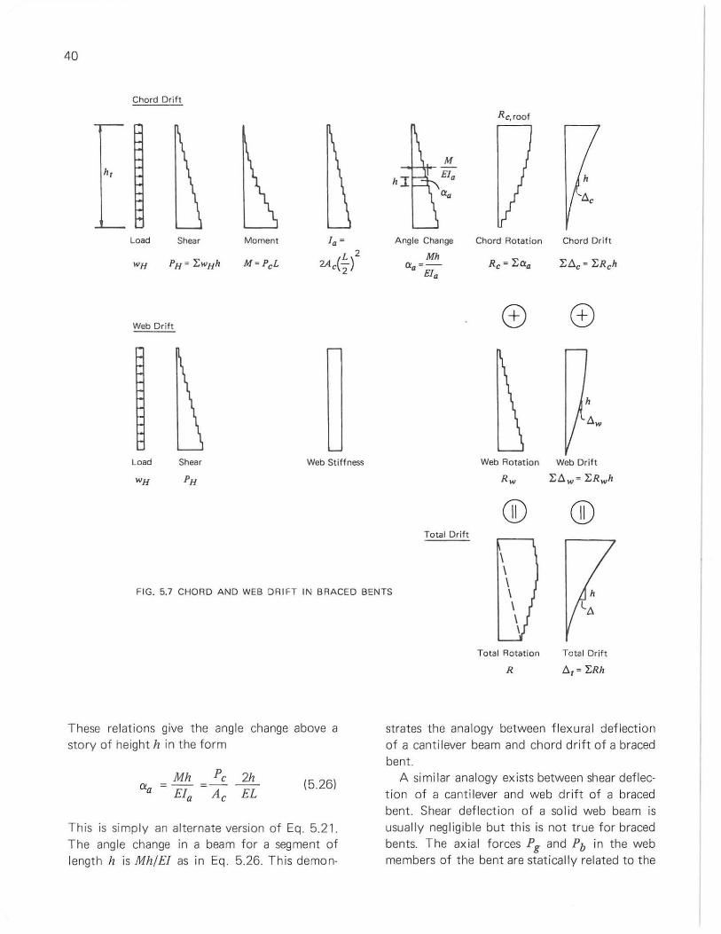
40
Chord Drift
Rc,roof
Load Shear Moment fa ~ Angle Change Chord Rotation Chord Drift
L 2 Mh wH PH" f.wHh M=PcL 2Ac(-2 ) " =- Re;' Laa f.t.c = f.Rch
a E1a
Web Drift 0 0
Load Shear Web Stiffness Web Rotation Web Drift
WH
CJD CD Total Drift
FIG. 5.7 CHOR D AND WEB DRIFT IN BRACED BENTS
These re lations give the angle change above a story of height h in the form
(526)
This is simply an alternate version of Eq. 5.21. The angle change in a beam for a segment of length h is MhIE! as in Eq. 5.26. This demon-
Total Rotation Total Drjft
R t., = f.Rh
strates the analogy between flexural deflection of a cantilever beam and chord drift of a braced bent.
A si mi lar analogy ex ists between shear deflection of a canti lever and web drift of a braced bent. Shear deflection of a solid web beam is usually negligible but this is not true for braced bents. The axial forces Pg and Pb in the web members of the bent are statica lly related to the
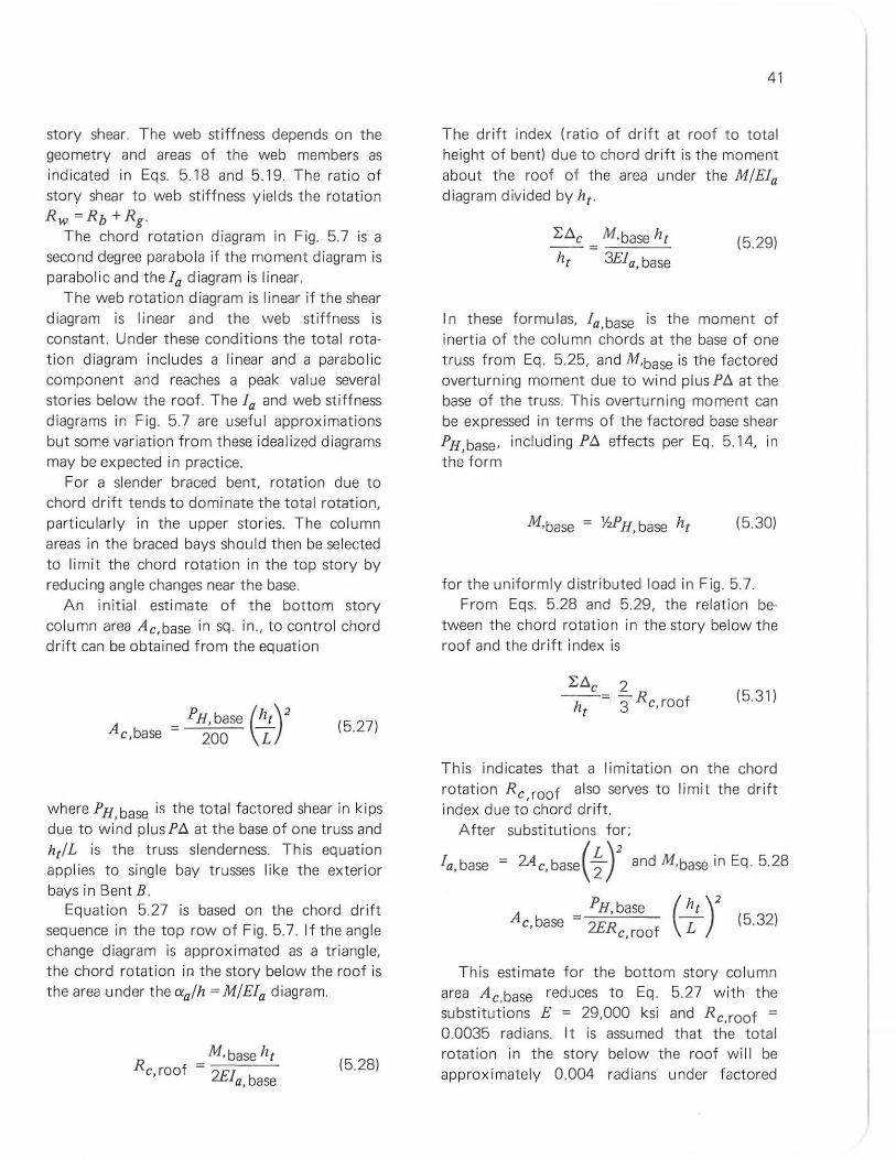
story shear. The web stiffness depends on the geometry and areas of the web members as indicated in Eqs 5.18 and 5.19. The rat io of story shear to web st iffness yields the rotation Rw~Rb+Rg.
The chord rotation diagram in Fig. 5.7 is a second degree para bola if the moment diagram is parabol ic and the fa diagram is linear.
The web rotation diagram is linear if the shear diagram is I inear and the web stiffness is constant. Under these conditions the tota l rotat ion diagram includes a linear and a parabol ic component and reaches a peak value several stories below the roof. The fa and web sti ffness diagrams in Fig. 5.7 are useful approximations but some variation from these idealized d iagrams may be expected in practice.
For a slender braced bent, rotation due to chord drift tends to dominate the total rotation, part icularly in the upper stor ies. The column areas in the braced bays should then be selected to limit the chord rotation in the top story by reducing angle changes near the base.
An init ial estimate of the bottom story co lumn area Ac,base in sq. in., to control chord drift can be obtained from the equation
Ac ,base ~ PH, base (hl)2
200 \L (5.27)
where PH, base is the total factored shear in k ips due to wind plus P~ at the base of one truss and hIl L is the truss slenderness. This equat ion applies to sing le bay trusses like the exterior bays in Bent B.
Equat ion 5.27 is based on the chord drift sequence in the top row of Fig. 5.7. If the angle change diagram is approximated as a triangle, the chord rotation in the story below the roof is the area under the OIalh = MIEfa diagram.
M,base hI R c, roof ~
2Efa base (528)
41
The drift index (ratio of drift at roof to total height of bent) due to chord drift is the moment about the roof of the area under the MIE1a diagram divided by hI
L~C M,base hI
~ ~ ~fa,base (5.29)
I n these formulas, fa,base is the moment of inertia of the column chords at the base of one truss from Eq. 5.25, and M'base is t he factored overturning moment due to wind plusP~ at the base of the truss. This overturning moment can be expressed in terms of the factored base shear PH,base, including P~ effects per Eq 5.14, in the form
(530)
for the uniformly distributed load in Fig. 5.7. From Eqs. 5.28 and 5.29, the relation be
tween t he chord rotation in the story below the roof and the drift index is
(531)
This indicates that a limitation on the chord
rotation Rc,roof also serves to limit the dr ift index due to chord drift.
A fter substitutions for;
fa, base ~ 2A c, base(; Y and M,base in Eq. 5.28
PH, base Ac,base ~
2ERc, roof (5.32)
This estimate for the bottom story column area Ac base reduces to Eq. 5.27 with the substitutions E ~ 29,000 ksi and Rc,roof ~
0.0035 radians. It is assumed that the total rotation in the story below the roof will be approximately 0.004 radians under factored
42
combined load. Of this total rotation, 0.0035 radians is assumed for chord drift , leaving 0.0005
radians for web drift. Other values of Rc,roof can be used in Eq. 5.32 to alter the chord st iffness of the vert ica l bracing system. This equation is independent of the column yie ld stress and the truss web system.
I n apply ing Eq 5.27 to Bent B, note that two identical trusses resist the wind plus Pt:. shears, so PH,base is one-half of the base shear from Tab . 8. 12(8) below level 24. With PH base =
652/2 = 326 kips under factored combi~ed load and a truss slenderness htlL = 8.8 for Bent B, Eq. 5.27 gives Ac,base = 126 in.2 below level 24 for chord drift control.
Th is column area may be compared with that needed to resist the critical combinat ion of factored axial load and bending. The factored axia l loads are obtained f rom Tab. 8.11 (4) and (9) for gravity load and Tab. 8.13(8) and (9) for combined load. Using the largest va lue, P = 2851 kips for the interior columns under factored combi ned load, and assuming PIPy = 0.7 and A36 steel, a column area of 2851/(0.7 x 36) = 114 in.2 is estimated below Level 24 to resist the factored axial load. The va lue PIPy = 0.7 is the ax ial load l imit in Eq. 5.17. The column area for chord drift contro l exceeds that estimated for factored ax ial load . Hence, the design example in Chapter 8, beginning wi th Tab. 8.16, assumes that stiffness requirements will contro l the design of braced Bent B. The calculations in Tabs. 8.10 to 8.15 are all based on stat ics and are needed regardless of what cri teri on is used to se lect member sizes.
The following articles describe a braced bent design method for selecting columns to control chord drift, and web members to contro l web drift.
5.8 CHORD DRIFT CONTROL
The rotation at the roof due to chord drift is the area under the angle change ( exalh ) diagram
Rc,roof = Y,kh t (~a) I base
(533)
where hI is the total height of the braced bent, k is a dimensionless coefficient, and (exalh )base denotes the "curvature" in the bottom story. Rearranging Eq. 5.21 gives,
(exa) Pc, base (2 ) h base = A c, base EL
(534)
From Eq. 5.33 and 5.34
Pc base (hI) Ac,base = k R' f EL c,roa
(5.35)
This result indicates that the column area at the base Ac,base is inversely proport ional to the rotation at the roof due to chord drift, and is dirertly proportional to the truss slenderness hIlL and to the axial load in the bottom story co lumns Pc,base due to wind plus Pt:.. Equation 5.35 is an alternate form of Eq 5.32 using axial force in the bottom story co lumns in place of base shear.
The dimensionless coefficient k in Eqs. 5.33 and 5.35 depends upon the shape of the moment and fa diagrams in Fig 5.7. The value k = 1.0 is a reasonab le first approximation and corresponds to:
1. A second degree parabola for the moment d iagram, and
2. A linear variation of co lumn area Ax with d istance hx above the base
(536)
Regard less of the shape of the moment and fa diagrams in Fig. 5.7, an improved est imate fo r k can be obtained as follows:
1. Determine Ac,base f rom Eq. 5.35 for k =
1.0 and an assigned value Rc,roof (discussed later). Select a trial sec ti on for the bottom story columns in the braced bays.
2. Select tria l sections for t he columns above using Eq. 5.36 or any other appropriate variation of column areas.
3. Determine the ang le changes Ci and Cia
above each level using Eqs 5.20 and 5.21. 4. Determine the chord rotation Rc below the
roof from Eq . 5.22. 5. An improved estimate fo r k is kRc/Rc,roof
These five steps represent one cycle of an iterative loop, and can be repeated using the improved estimate f or k in Step 1. The loop converges when Rc in Step 4 is approximately equal to Rc, roof in Step 1. Convergence is obtained in the second cyc le for the examp le described subsequently.
The column areas in the braced bays of Bent B decrease with increasing values of Rc,roof in Eq. 5.35. However, Rc, roof shou ld be taken as less than 0.004 radians for the reasons cited at the end of Art. 5.6, and to allow for rotation due to web drift in the top story of Bent B. The assumption
Rc,roof = 0.0035 radians (5.37)
is used in the design example. If larger values of Rc,roof are assumed, the story rotations will tend to exceed 0.0025 under working wind load and 0.004 under factored comb ined load. If smal ler values of Rc,roof are used, the column areas become excessive in this example.
Columns for Bent B are selected for chord drift control in Tab. 8.16. Step 1 shows the application of Eq. 5.35 to determine the area of the bottom story co lumns, using k = 1.2. This k value is the result of calculations described later.
Step 2 uses Eq. 5.36 to estimate column areas for the stories above the base level as shown in Tab. 816(3). The next three tabular columns
43
list tria l sect ions, areas, and axia l loads Pc due to wind plus P!:J,. Note that 14V1F426 in the bottom story does not meet the estimated area requirement. A coverplated or "jumbo" column section cou ld be selected but th is is not done in order to demonstrate the flexibi lity of the method.
The ang le changes Cia due to chord drift (F ig. 56c) are recorded in Tab. 8.16(7). Note (1) indicates how Eq. 5.21 is app lied in this calculat ion. The angle changes Cia are summed from the base in Tab. 8.16(8). This gives the rotation due to chord drift Rc according to Eq. 5.22. The value Rc = 0.00353 radians below the roof
agrees with the assumption Rc, roof = 0.0035 rad ians in step 1. Th is verifies the cho ice k = 1.2.
The columns in Tab. 8.16 satisfy the tentat ive rotation criterion for chord drift. These sections are checked for beam-column capacity in Art. 6.2.
The success of this design method for chord drift control depends in part on the choice of k in Eq. 5.35. Note that the method provides a check on the va lue assumed for k. T he value k =
1.2 in Tab. 8.1 6 was obtai ned from one cyc le of the f ive steps outl ined previously. The calculat ions used the same format as Tab. 8.16 with the results summarized be low:
Step 1. Ac,base = 120 in 2
for Rc,roof = 0.0035 rad ians and k = 1.0
Step 2.
Level Tr ial Level Tr ial Level Tria l Section Section Section
2 12V1F40 10 14V1F150 18 14V1F287
4 12V1F50 12 14V1F184 20 14V1F320
6 12V1F85 14 14V1F219 22 14V1F370
9 12V1F120 16 14V1F264 24 14V1F426
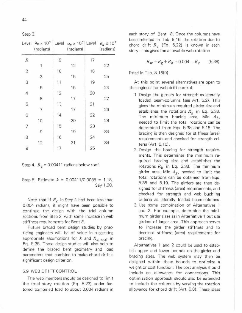
44
Step 3.
Level Cia x 105 Level Cia x 105 Level Cia X 105
(rad ians) (radians) (radians)
R 9 17 12 22
2 10 18 3 15 25
3 11 19 5 15 24
4 12 20 8 17 27
5 13 21 7 17 26
6 14 22 10 20 28
7 15 23 9 19 34
8 16 24 12 21 34
9 17 25
Step 4. Re ~ 0.00411 radians below roof.
Step 5. Estimate k ~ 0.004 11 /0.0035 ~ 1.18. Say 1.20.
Note that if Re in Step 4 had been less than 0.004 radians, it might have been possible to continue the design with the t rial column sect ions from Step 2, with some increase in web stiffness requ irements f or Bent B.
Future braced bent design studies by practicing engineers will be of value in suggesting appropriate assumptions for k and Re,roof in Eq . 5.35. These design studies wi ll also help to define the braced bent geometry and load parameters that combine to make chord drift a sign ificant design criterion.
5.9 WEB DRI FT CONTROL
The web members should be designed to limit the tota l story rotation (Eq. 5.23) under factored comb ined load to about 0.004 radians in
each story of Bent B. Once the columns have been selected in Tab. 8.16, the rotation due to chord drift Re (Eq. 5.22) is known in each story. This gives the allowable web rotation
(5.38)
li sted in Tab. 8.16(9).
At this point severa l alternatives are open to the engineer for web drift contro l:
1. Design the girders for strength as laterally loaded beam-columns (see Art. 5.2). This gives the minimum required girder size and establishes the rotations Rg in Eq . 5.38. The min imum bracing area, Min Ab,
needed to limit the total rotations can be determi ned from Eqs. 5.38 and 5.18. The bracing is then designed for stiffness (area) requirements and checked for strength criteria (Art . 5. 10).
2. Design t he bracing for st rength requirements. This determines t he min imum required bracing size and establishes the rotations Rb in Eq . 5.38. The minimum girder area, Min Ag , needed to limit the tota l rotations can be obtained from Eqs. 5.38 and 5.19. The girders are then designed for stiffness (area) requi rements, and checked for strength and web buckl ing criteria as laterally loaded beam-columns.
3. Use some combination of Alternatives 1 and 2. For example, determine the minimum girder sizes as in Alternative 1 but use girders of larger area. This approach serves to increase the girder stiffness and to decrease stiffness (area) requirements for bracing.
Alternatives 1 and 2 cou ld be used to establish upper and lower bounds on the girder and bracing sizes. The web system may then be designed with in these bounds to optimize a weight or cost function . The cost analysis should include an all owance for connect ions. This opti mization approach should also be extended to include the co lumns by varying the rotation al lowance for chord drift (Art. 5.8). These ideas
suggest the potential for future developments in the field of braced mu Itistory frames.
Alternative 1 is illustrated in the design example. The girders in Bent B are selected for factored combined load in Tab. 8.17. The girders are designed as laterally loaded beamcolumns using Eq. 5. 10 as explained in Art. 5.2. On Levels 2 to 8 in the exterior bays, the 1 OB 19 girders selected for factored gravity load in Tab. 8.9( 17) are also adequate for factored combined load. Below Level 8, combined load requi res an increase in the girder sizes as shown in Tab. 817(5) .
Web drift ca lculations for the girders are performed in Tab. 8.18. Step 1 shows how Eq. 5.19 is appl ied to give the rotation Rg in Col. (4)
The quantity Rw - Rg in Tab. 8. 18(5) represents the allowable rotation for the Kbracing. Equation 5.18 is used in Step 2 to determine the min imum K-brace area, Min Ab, needed to limit rotation. T he va lues of Min Ab in Col. (7) increase f rom the roof to Level 7, and then decrease from Level 7 to 24. If the minimum required bracing area exceeds that for bracing members of practical size, the girders can be increased as in A lternative 3.
5.10 DESIGN OF K-BRACING
There are th ree design criteria that are likely to control the K-bracing areasAb in Bent B:
1. The tension capacity AbFy must exceed the max imum K-brace tension in Tab. 815(5)
2. The compression capacity AbFcr must exceed t he maximum K-brace compression in T ab. 815(6) Eq. 3.5 gives the buckling stress Fer.
3. The bracing area should satisfy the minimum st iffness requirement in Tab. 8.18(7) .
The bracing stiffness requirement stems from the limitation R = 0.004 radians for the story rotation under factored combined load. No serious consequences should resu lt from exceeding this limitation by several percent. See Art. 5.1 1. Thus, the values of Min Ab in Tab. 8.18(7)
45
may be regarded as a guide to acceptable bracing stiffness rather than an absolute minimum design requ irement.
Two add itional design criteria should be considered for the bracing . The AISC Specificat ion limits the slenderness rat io for compression members to 200 and for tension members to 300. The bracing stiffness must also be adequate to prevent sidesway buckling of the bui lding under factored gravity load as discussed in Chapter 6.
The K-bracing for Bent B is designed in Tab. 8.19 using weldable pipe with Fy = 36 ksi. Pipe is an efficient section for bracing members that must resist compression. The information known when the bracing design commences is recorded in the lower half of each l ine in Tab. 8.19 and includes: the minimum area requirement in Col. (3)' the length, Net Lb , in Col. (4), and the maximum K-brace compression and tension in Cols. (7) and (8). The net buckling length of the bracing is less than the total length as suggested in Note (1).
T he trial pipe size for the K-bracing in Tab. 8. 19(2) is selected using the minimum area requirement as a guide. The brace area, radius of gyration, slenderness, and buck ling stress are entered in Cols. (3) to (6). The trial brace is adequate for strength criteria if the allowable (u ltimate) compression and tension capacity in Cols. (7) and (8) exceeds the maximum values recorded previously.
Above Level 23, the K-bracing f or Bent B is controlled by stiffness (area) requirements in Tab. 8.19. The maximum K-brace forces are less than 75 percent of t he tension and comp ression capacity above level 23. The K-bracing is stable and elastic (including a residual stress allowance) under factored combined load. Note that these bracing cond itions are assumed in the design of the K-braced girders (Art. 5.2) and in the drift equations (Art. 5.6). I n the bottom story of Bent B, the inverted K-brace, t he absence of chord drift and the 12 ft . story height combine to make compression strength the contro l ling design criterion for the K-bracing.
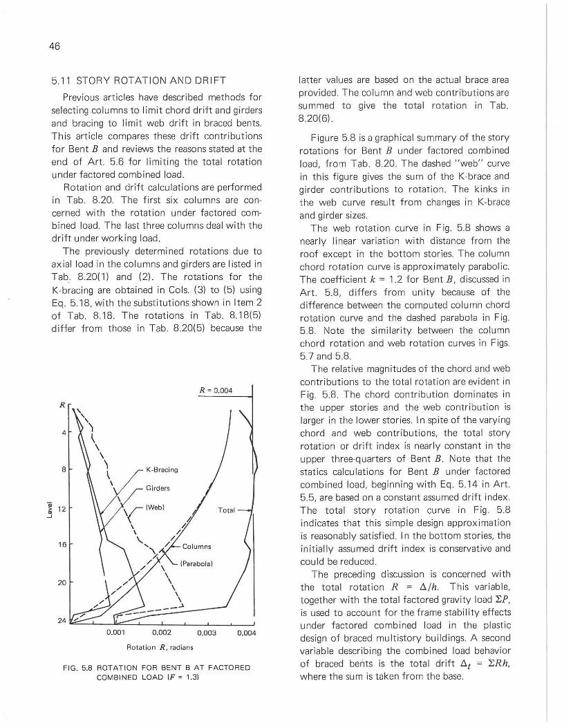
46
5.11 STORY ROTATION AND DRIFT
Previous articles have described methods for se lect ing columns to l imit chord drift and girders and bracing to limit web drift in braced bents. This art icle compares these drift contributions for Bent B and rev iews the reasons stated at the end of Art. 5.6 for limiting the tota l rotat ion under factored combined load.
Rotation and drift calculations are performed in Tab. 8.20. The first six co lumns are concerned with the rotation under factored combined load. The last three co lumns deal with the drift under working load.
The previously determi ned rotations due to axial load in the columns and girders are l isted in Tab. 8.20( 1) and (2). The rotations for the K-bracing are obtained in Co Is. (3) to (5) using Eq. 5.18, with the substitutions shown in Item 2 of Tab. 8.18 . The rotations in Tab. 8.18(5) differ from those in Tab . 8.20(5) because the
R = 0.004
R , , , 4
') , , , 8 \ K-Bracing
~ \
Girders
\ ID
12 ,(Iwebl Total > • -' # \ /, \ /
'- / 16 , / Columns
\ / (Parabola)
/ \ \
20 \ \
\ \
-,- _------.J. "/
24 / , 0.001 0.002 0.003 0.004
Rotation R. radians
FIG. 5.8 ROTAT ION FOR 8ENT 8 AT FACTOREO COMBI NED LOAD IF = 1.31
latter va lues are based on the actual brace area provided. The column and web contributions are summed to give the tota l rotat ion in Tab. 820(6).
Figure 5.8 is a graph ical su mmary of the story rotations for Bent B under factored comb ined load, from Tab. 8.20. The dashed "web" curve in th is figure gives the sum of the K-brace and girder contribut ions to rotation. The kinks in t he web curve result from changes in K-brace and girder sizes.
The web rotation curve in Fig. 5.8 shows a nearly linear variation with distance from the roof except in the bottom stories. The column chord rotat ion curve is approximately parabolic. The coefficient k = 1.2 for Bent B, discussed in Art. 5.8, differs from un ity because of the difference between the computed column chord rotation curve and the dashed parabola in Fig. 5.8. Note the simi larity between the column chord rotation and web rotat ion curves in Figs. 5.7 and 5.8.
The relative magn itudes of the chord and web contributions to the total rotat ion are evident in Fig. 5.8. The chord contribution dominates in the upper stories and the web contr ibution is larger in the lower stories. I n spite of the varying chord and web contributions, the total story rotation or drift index is nearly constant in the upper three-quarters of Bent B. Note that the statics calculations for Bent B under factored combined load, beginn ing with Eq. 5.14 in Art. 5.5, are based on a constant assumed drift index. The total story rotation curve in Fig 5.8 indicates that this simple design approximat ion is reasonably satisfied. I n the bottom stories, the init ially assumed dr ift index is conservative and could be reduced.
The preceding discussion is concerned with the total rotation R = Il/h. This variable, together with the tota l factored gravity load "J;P, is used to account for the frame stability effects under factored combined load in the plastic design of braced mult istory buildings. A second variable describing the combined load behavior of braced bents is the total drift Il t = "J;Rh, where the sum is taken from the base.
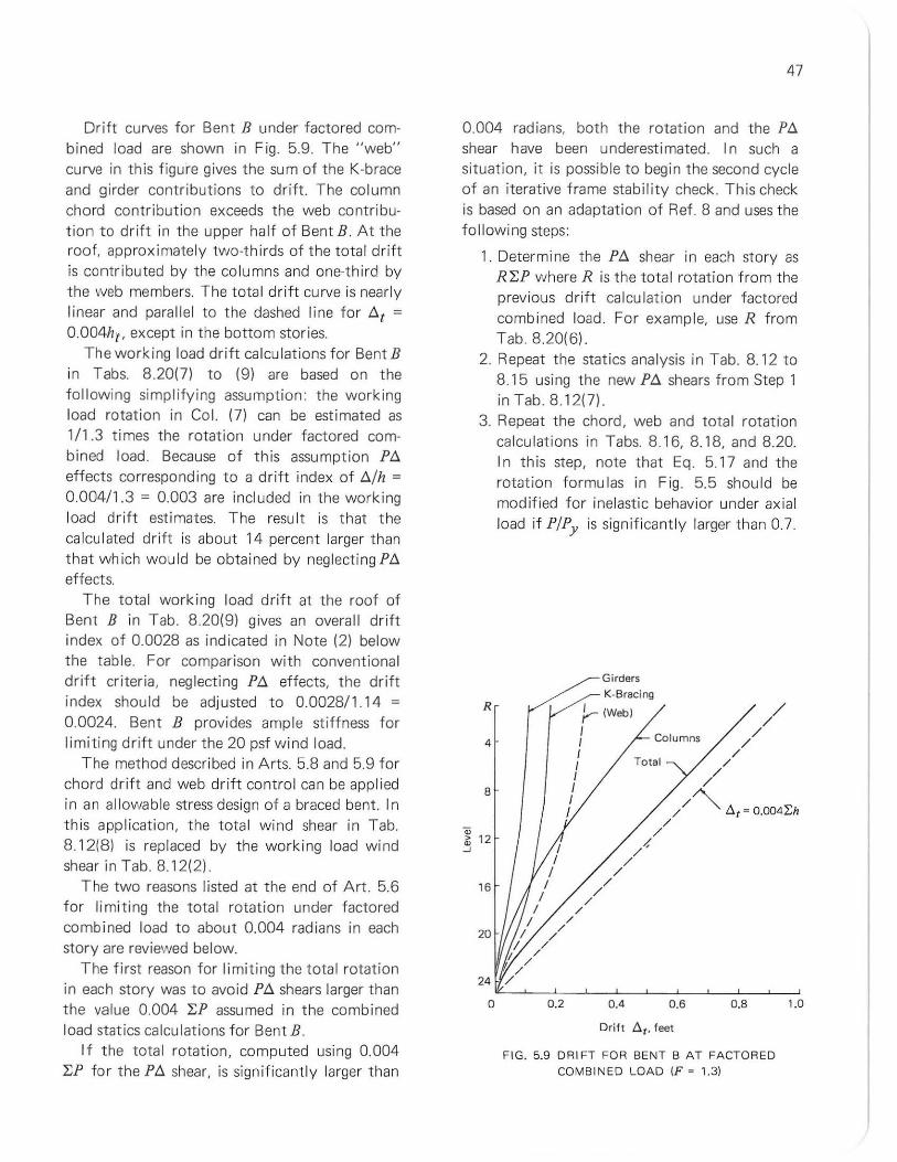
Drift curves for Bent B under factored combined load are shown in Fig. 5.9. The "web" curve in this figure gives the sum of the K-brace and girder contr ibutions to drift. The column chord contribution exceeds t he web contributi on to drift in the upper ha lf of Bent B. At the roof, approximately two-thirds of the total drift is contributed by the columns and one-th ird by the web members. The total drift curve is nearly linear and parallel to the dashed line f or At =
0004111, except in t he bottom stories. The working load drift ca lcu lat ions for Bent B
in Tabs. 8.20(7) to (9) are based on the fo l lowing simplifying assumpt ion: the work ing load rotat ion in Col. (7) can be est imated as 1/1.3 times the rotation under factored combined load. Because of this assumption PA effects corresponding to a drift index of A/l! =
0.004/1 .3 = 0.003 are incl uded in the working load drift esti mat es. The result is that t he calculated dri ft is about 14 percent larger t han that which would be obtained by neglecting PA effects.
The t otal working load drift at the roof of Bent B in Tab. 820(9) gives an overall drift index of 0.0028 as indicated in Note (2) below t he tab le. For comparison with conventional drift criteria, neglecting PA effects, t he drift index should be adjusted to 0.0028/1.1 4 =
0.0024. Bent B provides ample stiffness for limiting drift under the 20 psf wind load.
The method described in Arts. 5.8 and 5.9 for chord dr ift and web drift control can be applied in an al lowa ble stress design of a braced bent. In this application, the total wind shear in Tab. 8.12(8) is replaced by t he working load wind shear in Tab. 8. 12(2).
The two reasons listed at the end of Art. 5.6 f or limiting the total rotation under factored combined load to about 0.004 radians in each story are reviewed below.
The first reason for limiting the total rotation in each story was to avoid PA shears larger than the value 0.004 "LP assumed in the combined load statics calculat ions f or Bent B.
I f the total rotat ion, computed using 0.004 "LP for the PA shear, is significant ly larger than
47
0.004 radians, both the rotation and the PA shear h ave been u nderest i mated. I n such a situat ion, it is possible to begin the second cycle of an iterative frame stability check. This check is based on an adaptat ion of Ref . 8 and uses the following steps:
1. Determine the PA shear in each story as R"LP where R is t he total rotation from the prev ious drift calcu lation under factored comb ined load. For examp le, use R from Tab. 820(6).
2. Repeat the stat ics analysis in Tab. 8.12 to 8. 15 using the new PA shears from Step 1 in Tab. 8. 12(7).
3. Repeat the chord, web and tota l rotation ca lculations in Tabs. 8.16, 8.18, and 8.20. In this step, note that Eq. 5. 17 and the rotation formulas in Fig. 5.5 should be modified for inelastic behavior under axia l load if P/Py is significantly larger than 0.7.
R
4
B
16
20
o 0.2
Girders
K·Bracing
),-- IWebl
I Columns I I I I I I I
Total
0.4 0.6
Drift D. t . feet
O.B
FIG . 5.9 DRIFT FOR BENT B AT FACTORED
COMB INED LOAD IF · 1.31
1.0
48
Alternatively, member sizes may be increased to satisfy this limitat ion on PIPy .
4. If the total rotations obtained in Step 3 are equal to or smaller than the corresponding values from Step 1, the iteration is said to have converged and the bent is stable under the factored combined load. If this is not the case, two alternatives are open. a. Repeat the cycle using the tota l rota
tions from Step 3 (or larger values to speed convergence) in place of the previous rotations in Step 1.
b. If the rotations in Step 3 are large (say on the order of two t imes the working load drift criterion), the members that make the larger contributions to the tota l rotation should be increased in size.
Th is iterat ive stability check for braced multistory bents under factored combined load follows well defined steps, but can become protracted for a ta l l bent. I t is not expected that this stability check method wil l find frequent app licat ion in practice. It is included here to indicate the possible sign if icance of calcu lated tota l rotations that exceed the rotat ion used to est imate the P!l shears by a substantial margin.
I n severa l stories, the calcu lated total rotat ions for Bent B in Tab. 8.20(6) exceed, by a small margin, the value 0.004 radians used to estimate P!l shears in Tab. 8.12(7) This does not necessarily indicate the need for a combined load stability check. For example, consider the factored shears below Level 7 of Bent B.
Wind shear 165 kips Tab.812(3) P!l shear = 24.2 kips based on R = 0.004
radians Tab. 8.12(3) P!l shear 24.8 kips based on R = 000409
radians
The increase in total rotat ion causes only a sma l l change in the P!l shear. From another viewpoint, a 3 percent or 4.9 kip change in the factored w ind shear corresponds to a 20 percent change in the initially assumed P!l shear for Bent B. Unless the P!l shear is a substantia l portion of the total shear in the story, sma ll differences between the initially assumed and calculated tota l rotat ion do not produce significant changes in the tota I story shear.
The second reason for limiting t he total rotation under factored combined load was to satisfy the drift criterion under working wind load. The adjusted work ing load dr ift index of 0.0024 for Bent B is within acceptab le drift limits.
For a working load drift index of 0.003 many of the columns in Bent B can be reduced by about two sizes. The drift criterion is significant in determining the weight of steel in a braced bent. I n present practice, the cho ice of a drift index depends on the engineer's judgment. Research is needed to assist the engineer in making his choice.
The resu Its of the tentative design of braced Bent B are summarized in Fig. 8.2; these are to be checked in Chapter 6.
49
CHAPTER 6
Design Checks and Secondary Considerations
6.1 INTRODUCTION
The pri mary stage of a structural design is usually concerned with the proportioning of members for strength and/or stiffness. The design conditions considered are full factored gravity loading, factored combined. loading, and w ind drift. I n Chapter 5 drift was chosen as the govern ing design condition for the columns in Bent B. I n this chapter the strength of these co lu mns will be checked for gravity load (F =
1.7) and combined load (F = 1.3). I n addition there are secondary cond itions
(secondary meaning that they are not usually considered in the initial design) that may govern the design of individual elements in the structure. These condi tions are:
1. partial live or "checkerboaro" loading 2. deflections at working load 3. sidesway under facto red gravity load 4. spacing of lateral bracing 5. effect of shear on bending capacity 6. upli ft at footings
The approach used for these design checks is to make conservative assumptions and approximations in order to find out if there is a problem in the first place. If the preliminary conservative ca lcu lations do not satisfy the particular requ irement, then more careful analysis is performed. T he idea is that usually the secondary design situations are not crit ical, so they do not warrant undue design time.
6.2 DES IGN CHECKS, BENT B-FACTORED GRAVITY AND COMB INED LOAD
The girders in Bent B have been designed for factored gravity and combined loading in Tabs. 8.9 and 8.17. The co lumns in Bent B, however, have been selected for chord drift control in
Tab. 8.16, so they must be checked for adequate strength to support the factored gravity load (F
= 1.7) and factored combined load (F = 1.3l.lt will be necessary to check both load ing conditions for beam-column strength.
The calculat ions for the column check are si mi lar to those for the design of the Bent A columns given in Tabs. 8.6 and 8.8. First the moments applied to the columns through the girders are evaluated in Tab. 8.21. In determining the net girder moments that are applied to the columns, it is assumed that Mp occurs at the ends of the girders only for the part icular loading cond it ion that controlled the girder size. For other loading conditions it is assumed the girder is elastic, and the end moment is, conservatively, the fixed -end moment FEM. An upper limit is placed on the fixed-end moment equal to the bending capacity of the girder. Factored comb ined load (F = 1.3) governed the size of the girders in the exterior bay, whereas the girders in the interior bay were selected on the basis of factored gravity load (F = 1.7). Consequent ly, it is assumed that the exterior-bay girders are elastic at F = 1.7 and the interior-bay girders are elastic at F = 1.3. The girder moments at the column centerline Mj are calculated by increasing the clear span moments Me by the quantity y.. FWLgdc (end shear x one-half the co lumn depth). The net girder moment is assumed to be equally divided between the two columns at a joint.
I n Tab. 8.22, the axial loads and moments in the columns are compared for the two loading cases in order to determine the controlling cond it ions. Only a few representative columns are compared in this check, and an aster isk (*)
indicates the more crit ical loading condit ion. From Tab. 8.22, the check of the top story columns is governed by factored gravity load,
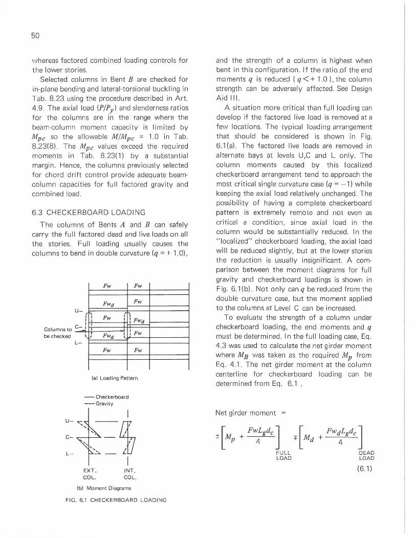
50
whereas factored combined loading contro ls for the lower stories.
Selected columns in Bent B are checked for in-plane bending and lateral-torsional buckling in Tab. 8.23 using the procedure described in Art . 4.9. The ax ial load (P/Py ) and slenderness ratios for the co lumns are in the range where the beam-co lumn moment capacity is limited by Mpc so the allowable M/Mpc = 1.0 in Tab. 8.23(8). The Mpc values exceed the required moments in Tab . 8.23( 1) by a substantial margin. Hence, the columns previously selected for chord drift control provide adequate beamco lumn capacities for full factored gravity and combined load.
6.3 CHECKERBOARD LOADING
The colu mns of Bents A and B can safely carry the full factored dead and live loads on all the stories. Full loading usually causes the co lumns to bend in double curvature (q = + 1.0),
Columns to be checked
U-
C
L-
Fw Fw
FWd Fw
rn Fw ,-
I I I : FWd I I
\ , FWd I ! Fw ,
Fw Fw
(a) Loading Pattern
- Checkerboard --- Gravity
EXT. COL.
INT . COL.
(b) Moment Diagrams
FIG. 6.1 CHECKERBOARO LOAOING
and the strength of a column is highest when bent in this configurat ion. If the ratio .of the end moments q is reduced ( q < + 1.0), the column strength can be adversely affected. See Design Aid I II .
A situat ion more critical than ful l load ing can develop if the factored I ive load is removed at a few locations. The typ ical loading arrangement that should be considered is shown in Fig. 6.1 (a) . The factored live loads are removed in alternate bays at levels U ,C and L only. The column moments caused by th is localized checkerboard arrangement tend to approach the most critical single curvatu re case (q = - 1) while keeping the axial load relat ively unchanged The possibility of having a complete checkerboard pattern is extremely remote and not even as critical a cond ition, since axial load in the column wou ld be substantially reduced. In the " local ized" checkerboard loading, the axia l load wi ll be reduced sl ightly, but at the lower stories the reduct ion is usually insign ificant. A comparison between the moment diagrams for full gravity and checkerboard loadings is shown in Fig 6.1 (b). Not on ly can q be reduced f rom the double curvature case, but the moment applied to the co lumns at Level C can be increased.
To eva luate the strength of a co lumn under checkerboard load ing, the end moments and q must be determined. I n the fu l l load ing case, Eq. 4.3 was used to calculate the net girder moment where ME was taken as the requi red Mp from Eq. 4.1. The net girder moment at the column center li ne for checkerboard loading can be determined from Eq . 6.1 .
Net girder moment =
± [Mp + FW:gdcJ + [ Md
FULL LOAD
+ FW~Lgdc ] DEAD LOAD
(61)
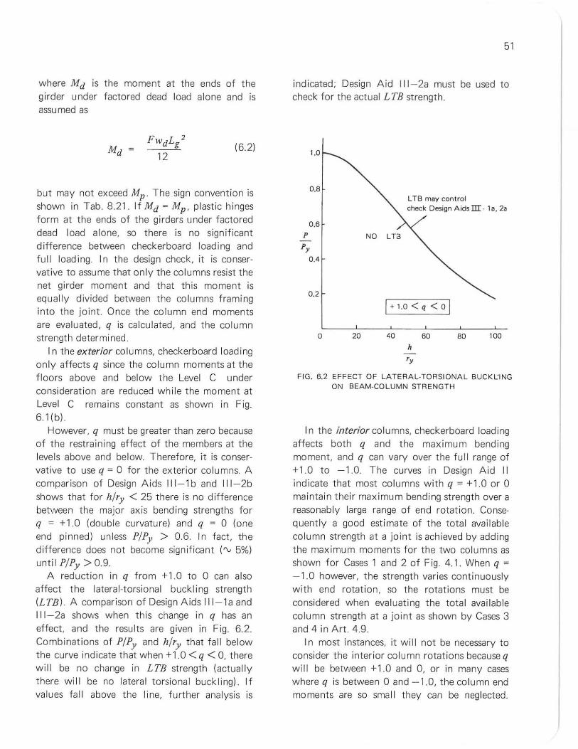
where Md is the moment at the ends of the girder under factored dead load alone and is assumed as
(52)
but may not exceed Mp . The sign convention is shown in Tab. 8.21. If Md = Mp ' plast ic hinges form at the ends of the girders under factored dead load alone, so there is no significant difference between checkerboard loading and full load ing. In the design check, it is conservative to assume that only the columns resist the net girder moment and that t his moment is equally divided between the co lumns framing into the joint. Once the column end moments are eva luated, q is calculated, and the column strength determined.
I n t he ex terior co lumns, checkerboard loading only affects q since the column moments at the floors above and below the Level C under consideration are reduced wh ile the moment at Level C remains constant as shown in Fig. 51{b)
However, q must be greater than zero because of the restraining effect of the members at the levels above and below. Therefore, it is conservative to use q = 0 for the exterior columns. A comparison of Design Aids 111-1 band 111-2b shows that for h/ry < 25 there is no difference between the major axis bend ing strengths for q = + 1.0 (double curvature) and q = 0 (one end pinned) unless P/Py > 0.5. In fact, the difference does not become significant ('\, 5%) until P/Py > 0.9.
A reduction in q from + 1.0 to 0 can also affect the lateral-torsional buckl i ng strength (LTB) A comparison of Design Aids III - la and 111 - 2a shows when this change in q has an effect, and the results are given in Fig. 5.2. Combinat ions of P/Py and h/ry that fall below the curve indicate that when +10 < q < 0, there wil l be no change in LTB strength (actually there wi ll be no lateral torsional buckling) If va lues fal l above the line, f urt her analysis is
51
ind icated; Design Aid 111 - 2a must be used to check for the actual LTB strength .
1.0
0,8
0.6
P
Py
0.4
0.2
a 20
L TB may con trol check Design Aids III - 1 a, 2a
NO LT3
I + 1.0 < q < a I
40 60 80 100
h
FIG. 6.2 EFFECT OF LATERAL· TORSIONAL BUCKLING ON BEAM·CO L UMN STRENGTH
I n the interior columns, checkerboard loading affects both q and the maximum bending moment, and q can vary over the full range of +1.0 to -1.0. The curves in Design Aid II indicate that most co lumns with q = +1.0 or 0 ma intain their maximum bending strengt h over a reasonably large range of end rotat ion. Consequent ly a good esti mate of the tot al availab le co lumn strength at a joint is achieved by adding the maximum moments for the two columns as shown for Cases 1 and 2 of Fig. 4.1. When q =
- 1.0 however, the strength var ies continuously with end rotation, so the rotat ions must be considered when evaluating the tota l avai lable co lumn strength at a joint as shown by Cases 3 and 4 in Art. 4.9.
I n most instances, it will not be necessary to consider the interior column rotations because q will be between + 1.0 and 0, or in many cases where q is between 0 and -1.0, the co lumn end moment s are so sma ll they can be neg lected.
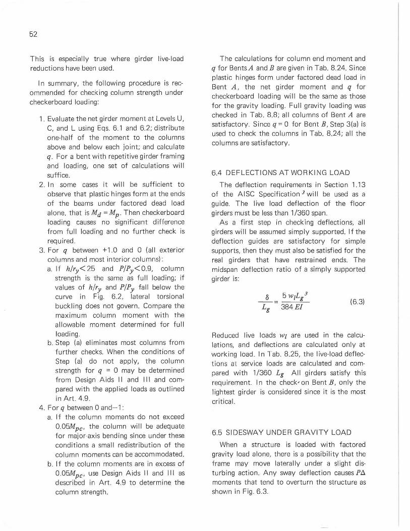
52
This is especially true where girder live-load reductions have been used.
I n summary, the fol lowing procedure is recommended for checking column strength under checkerboard loading:
1. Evaluate the net girder moment at Levels U, C, and L using Eqs. 6.1 and 6.2; distribute one-half of the moment to the co lumns above and below each joint; and calcu late q. For a bent with repetitive girder fram ing and loading, one set of calculations will suffice.
2. I n some cases it wil l be sufficient to observe that plast ic hinges form at the ends of the beams under factored dead load alone, that is Md = Mp. Then checkerboard loading causes no signif icant difference from full loading and no further check is required.
3. For q between +1.0 and 0 (al l exterior columns and most interior co lumnsl: a. If hlry<25 and PIPy <0.9, column
strength is the same as full loading; if values of hlry and PIPy fall below the curve in Fig. 6.2, lateral torsional buck ling does not govern. Compare the max imum column moment with the allowable moment determined for full loading.
b. Step (al eliminates most columns from further checks. When the cond itions of Step (al do not apply, the column strength for q = 0 may be determined from Design Aids I I and I II and compared with the applied loads as outlined in Art . 4.9.
4. For q between 0 and-1 : a. If the column moments do not exceed
O.05Mpc ' the co lumn wil l be adequate for major-axis bending since under these conditions a small redistribution of the co lumn moments can be accommodated.
b. I f the co lumn moments are in excess of 0.05Mpc ' use Design Aids II and II I as described in Art. 4.9 to determine. the column strength.
The calculations for column end moment and q for Bents A and B are given in Tab. 8.24. Since plastic hinges form under factored dead load in Bent A, the net girder moment and q for checkerboard loading wi l l be the same as those for the gravity loading. Full gravity loading was checked in Tab. 8.8; al l columns of Bent A are satisfactory. Since q = 0 for Bent B, Step 3(al is used to check the co lumns in Tab. 8.24; all the columns are sat isfactory.
6.4 DEFLECTIONS AT WORKING LOAD
The deflection requ irements in Section 1 13 of the A I SC Specificat ion 3 wi II be used as a guide. The live load def lection of the floor girders must be less than 1/360 span.
As a first step in checking deflections, all girders wil l be assumed simply supported. If the deflection guides are satisfactory for simple supports, then they must also be satisfied for the real girders that have restrained ends. The midspan deflection rat io of a simply supported girder is:
8 5 wiL/ - = ;::;:-:,,=--
Lg 384£1 (6.31
Reduced live loads WI are used in the calculations, and deflections are calculated only at working load . In Tab. 8.25, the l ive-load def lections at service loads are calcu lated and compared with 1/360 Lg All girders satisfy this requirement. In the check'on Bent B, only the lightest girder is considered since it is the most crit ical.
6.5 SIDESWAY UNDER GRAVITY LOAD
When a structure is loaded with factored gravity load alone, there is a possib il ity that the frame may move lateral ly under a slight disturbing action. Any sway deflection causes P/:" moments that tend to overturn the structure as shown in Fig. 6.3.
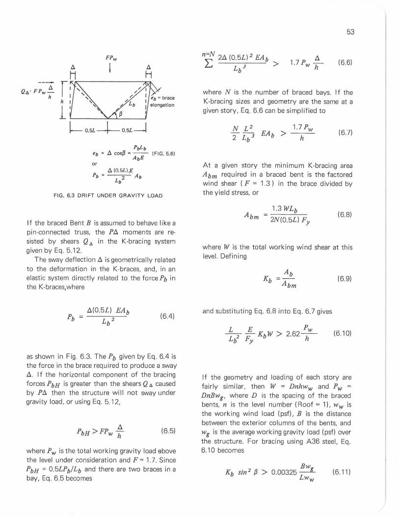
A Q",' FPw -
h
FPw
A I Hi<--___ -----,"'"
r ~ , 1 "
hi'
l' " ~ ~ O.5L --+- O.5L--J
PoLb eb • A cos~ • -- IFIG.5.61
AbE or
AIO.5L),E Pb = 2 Ab
Lb
FIG. 6.3 DRIFT UNDER GRAVITY LOAD
If the braced Bent B is assumed to behave like a pin-connected truss, the PI:,. moments are resisted by shears Q", in the K-bracing system given by Eq. 5.12.
The sway deflection I:,. is geometrically related to the deformation in the K-braces, and, in an elastic system di rectly related to the force Pb in the K-braces,where
(64)
as shown in Fig. 6.3. The Pb given by Eq . 64 is the force in the brace required to produce a sway 1:,.. If the horizontal component of the brac ing forces PbH is greater than the shears Q '" caused by PI:,. then the structure will not sway under gravity load, or using Eq. 5.12,
(65)
where Pw is the total working gravity load above the level under consideration and F = 1.7. Since PbH = 0.5LPb/Lb and there are two braces in a bay, Eq. 6.5 becomes
53
(66)
where N is the number of braced bays. If the K-bracing sizes and geometry are the same at a given story, Eq. 6.6 can be simp l ified to
1.7 Pw
h (67)
At a given story the minimum K-bracing area Abm required in a braced bent is the factored w ind shear (F = 1.3) in the brace div ided by the yield stress, or
1.3 WLb Abm :;
2N(0.5L) Fy (6.8)
where W is the total working wind shear at this level. Defining
and substituting Eq. 6.8 into Eq. 6.7 gives
Pw > 2.62-h-
(69)
(610)
If the geometry and loading of each story are fairly similar, then W = Dnhww and Pw = DnBwg , where D is the spacing of the braced bents, n is the level number (Roof = 11, Ww is the working wind load (psf), B is the distance between the exterior columns of the bents, and Wg is the average working gravity load (psf) over the structure. For bracing using A36 steel, Eq. 6.10 becomes
Bw 0.00325 .::..:.:.LL
Ww (6 11)
54
where f3 is the angle between the brace and the girder.
The structure wil l not sway under gravity load if Eq. 6.11 is satisfied at every level. However, if Eq 6.11 is satisf ied using Kb = 1.0 (the minimum possible value which corresponds to actual ly using the minimum bracing area), no further check is necessary. For the unusual case where usi ng Kb = 1.0 does not satisfy this equation, the actual Kb must be used and the equation checked at every level.
For the bent shown in Fig. 8.1 and assuming Kb = 1.0, Eq. 6.11 becomes
1.0
or 0.51 > 0.0069
103 psf' 20 psf
therefore the structure wi ll not sway under gravity load.
6.6 SPAC ING OF LATERAL BRACING
I n a braced mul t istory frame the moment d iagram at the girder design condit ion is shown in Fig. 6.4(a). Latera l bracing of the compression flange is required in the vicin ity of the plastic hinges to ensure that Mp can be reached and a mechanism can form. The lateral bracing requ irements are given in Tab. 3. 1. These requi rements can be given in a more convenient design form for a uniformly loaded girder by com· bin ing them with the moment diagram of Fig. 6.4 (a).
The requ ired bracing spacing at the plastic hinge locat ions (center and both ends) is given in Fig. 6.4(b) for A36 stee l. These rules were derived by determining t he range over wh ich a bracing ru le is applicable. For example, from Fig. 6.4(a), at t he center M/Mpe > 0.7 if
12195 x 27 + 140 x 12 • From the loads in Fig. 8.1, Wg =
66
11---- Lg -----II 1 r- 0.046Lg
Mp I O.7Mp
O.046Lg l [-Mp 0.7Mp
~--I---.,.L O.7Mp
M .194Lg .194Lg - >0.7 Mp
(a) Moment Diagram - Uniformly Loaded Beam
I A36 STEEL I SP:~ing I Center L ____ '-___ _
Lg
38,y
a 196 ry
Spacing at Ends'" 65 r y
ib) Design Aid for Bracing Spacing on A36 Beams
FIG. 6.4 SPACING OF BRACING FOR UN I FORMLY LOADED BEAM
Icr< 0.194Lg , SO ler = 38ry . Eliminating ler gives Lg/ry > 38/0 194 = 196. At the center if
Lg/ry > 196, then braces must be spaced at 38ry . For Lg/ry < 196, a spacing of 65ry is permissible. Thus it is only necessary to calculate Lg/ry
to determine the bracing spacing at the center. Bracing from the ends can be placed at 65ry .
For the 38ry rule to govern, it would be necessary to have a girder with a Lg/ry > 825. For rol led sections, such a girder cannot exist because deflection limitations would restrict the girder length to a much sma ller value.
The maximum bracing spacing for the com· pression f lange for the girders of Bents A and B
103 psi
Using live-load reductions could further reduce th is average gravity load.
are given in Tab. 8.26. As a practical consideration, bracing can be provided only at the joist locations. A tentative floor system design has established a 3-ft. joist spacing for the exterior bays and a 2-ft. spacing for the interior bay. The joists will be positively attached to the top f lange of the girders. Tab. 8.26 shows that in all cases, the allowable bracing spacing is greater than the jO ist spac ing so the top flange is adequately braced. Bracing may also be requ ired in t he compression regions of the bottom f lange. I n Bent A, a short length of the bottom f lange is in compression at the ends of the girder. Since the girder is r igid ly attached to the column and the length of the negative moment region is less than 65ry, no bracing is necessary. In Bent B, however, the exterior bay girders have a compression region at t he bottom flange at midspan where the K-brace connection is located. At th is point, bottom f lange bracing must be provided. This can be accomplished by we ld ing jOist chord extensions to the bott om f lange of the girder. In summary, the jo ists wi ll prov ide adequate topflange bracing f or t he girders. No other bracing is required for Bent A but the exter ior bay girders of Bent B require two bottom f lange braces near midspan as shown in Tab. 8.26.
6.7 EFFECT OF SHEAR ON BENDI NG CAPACITY
Eq. 3.3 gives the maximum allowable shear force which a member can resist . If the actua l
55
shear is greater, then the web of the section must be strengthened or the member size increased. The shear in the girders is checked in Tab. 8.27. The maximum applied shear is given by
Vmax (6. 121
from equ ilibr ium or symmetry. The largest shear occurs when F = 1.7. All girders f or Bents A and B are satisfactory as shown in Tab. 8.27.
6.8 UPLIFT AT FOOTINGS- BENT B
The eng ineer must provide for possible uplift forces at the footings of Bent B under combined load. An estimate of these upl ift forces is given in Tab. 8.28. At work ing load wind can cause 203 kips uplift at the exterior footing and 268 kips uplift at the interior foot ing. The exterior column uplift can be resisted by the exterior foundation wa ll carry ing shears to the adjacent Bents A. Interior co lumn uplift could be accommodated by bracing in the interi or bay at the bottom level.

56
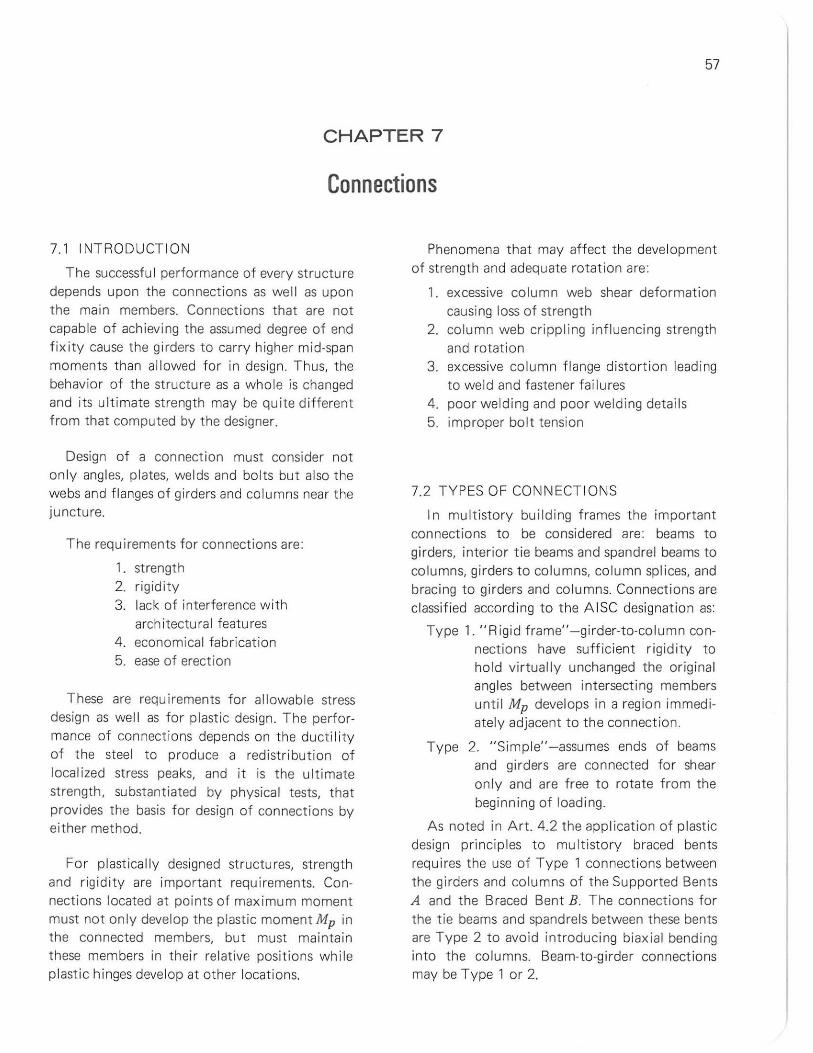
57
CHAPTER 7
Connections
7.1 INTRODUCT ION
The successful performance of every st ructure depends upon the connect ions as well as upon the main members. Connections that are not capable of achieving the assumed degree of end fixity cause the girders to carry higher mid-span moments than allowed for in design. Thus, the behavior of the structure as a whole is changed and its ultimate strength may be quite different from that computed by the designer.
Design of a connect ion must consider not on ly angles, plates, we lds and bolts but also the webs and f langes of girders and columns near the juncture.
The requirements for connections are:
1. strength 2. rigidity 3. lack of interference with
architectural features 4. economical fabrication 5. ease of erection
These are requirements for allowable stress design as wel l as for plastic design. The performance of connections depends on the ductil ity of the steel to produce a redistribution of localized stress peaks, and it is the ultimate strength, substantiated by physical tests, that provides the basis for design of connections by either method.
For plastically designed structures, strength and rigidity are important requirements. Connections located at points of maximum moment must not only develop the plastic moment Mp in the connected members, but must maintain these members in their re lative positions while plastic hinges develop at other locations.
Phenomena that may affect the development of strength and adequate rotation are:
1. excessive column web shear deformation causing loss of strength
2. column web crippling influencing strength and rotation
3. excessive co lumn f lange distortion leading to weld and fastener failu res
4. poor welding and poor weldi ng detai ls 5. improper bolt tension
7.2 TYPES OF CONNECT IONS
In multistory building frames the important connections to be considered are: beams to girders, interior tie beams and spandrel beams to columns, girders t o columns, column splices, and brac ing to girders and columns. Connections are cl assi fied according to the A ISC designat ion as:
Type 1. "Rigid frame"- girder-to-co lumn connections have sufficient r igid ity to ho ld virtually unchanged the orig inal ang les between intersecting members unti l Mp develops in a region immediately adjacent to the connection.
Type 2. "Simple" -assumes ends of beams and girders are connected for shear only and are free to rotate from the beginning of load ing.
As noted in Art. 4.2 the application of plastic design princip les to multistory braced bents requ ires the use of Type 1 connect ions between the girders and columns of the Supported Bents A and the Braced Bent B. The connections for the tie beams and spandre ls between these bents are Type 2 to avoid introducing biaxial bend ing into the columns. Beam-to-girder connections may be Type 1 or 2.
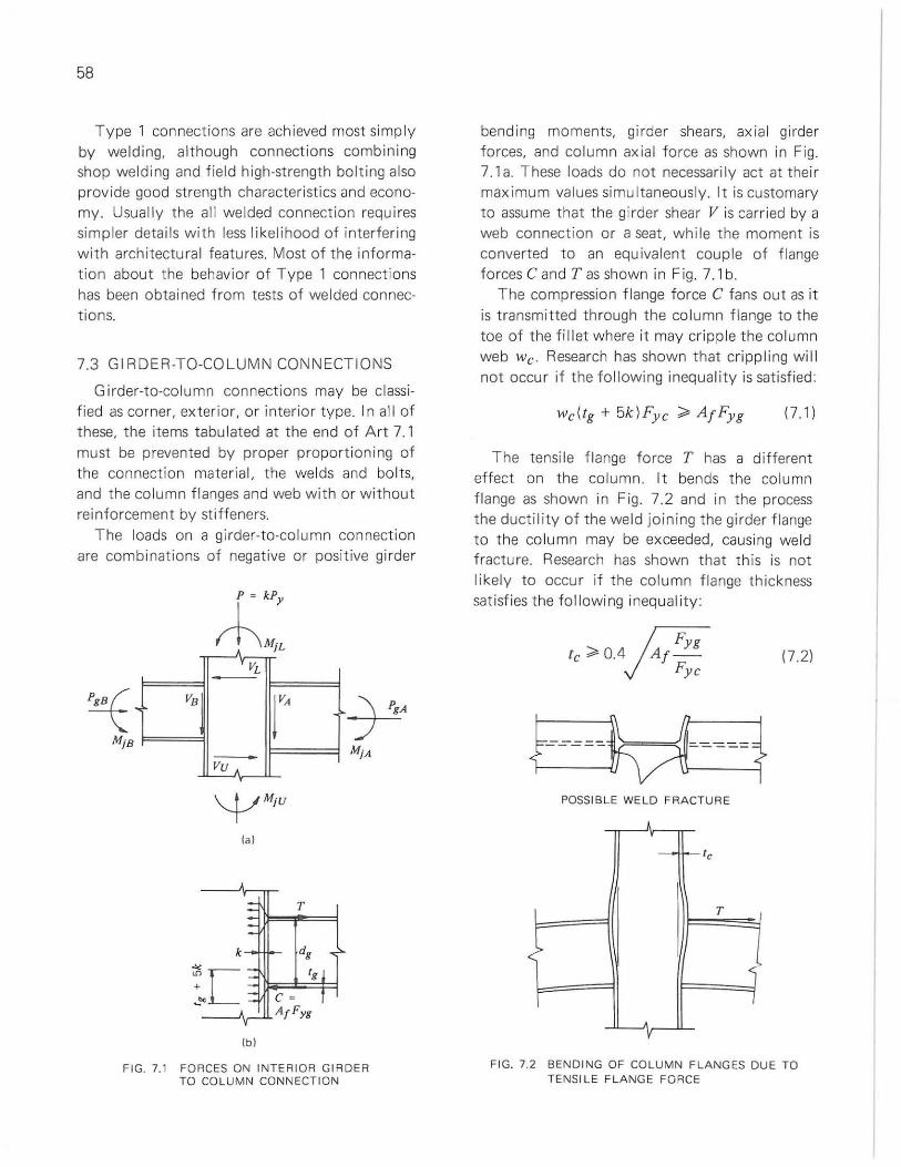
58
Type 1 connections are achieved most simply by we lding, although connections combining shop welding and field high-strength bolting also provide good strength characteristics and economy. Usual ly the all we lded connection requires simp ler details with less likelihood of interfering with architectural features. Most of the information about the behavior of Type 1 connections has been obtained from tests of welded connections.
7.3 GI RDER-TO-COLUMN CONNECTIONS
Girder-to-column connections may be classified as corner, exterior, or interior type. I n al l of these, the items tabu lated at the end of Art 7.1 must be prevented by proper proport ioning of the connection materia l, the we lds and bolts, and the column flanges and web with or without reinforcement by stiffeners.
The loads on a gi rder-to-column connection are combinations of negative or positive girder
,
Mi8
-v- VL
VB
-Vu A
k
""
r
T
:~C c · __ "Ir-~Af F yg
Ib)
FIG. 7.1 FORCES ON INTERIOR GIRDER TO COLUMN CONNECT ION
bending moments, girder shears, ax ial gi rder forces, and column axial force as shown in Fig. 7.1a. These loads do not necessarily act at the ir maximum values simultaneously. It is customary to assume that the girder shear V is carried by a web connect ion or a seat, while the moment is converted to an equivalent couple of flange forces C and T as shown in Fig. 7.1 b.
The compression flange force C fans out as it is transmitted th rough the co lumn flange to the toe of the fillet where it may cripp le the column web We. Research has shown that cri ppling will not occu r if the fo llowing inequali ty is satisf ied:
17.1 )
The tensile f lange force T has a different effect on t he column. It bends the column flange as shown in Fig. 7.2 and in the process the ductility of the weld joining the girder flange to t he co lumn may be exceeded, causing we ld fracture. Research has shown that this is not likely to occur if the column flange thickness sat isf ies t he following inequality:
R yg te ;;;. 0.4 Af
Fye
- - - -- --- --}---nM-----i POSSIB LE WELD FRACTURE
!
~ - Ie
T )
< j '
I
V
17.2)
FIG. 7.2 BENDING OF COLUMN FLANGES DUE TO TENSILE FLANGE FORCE
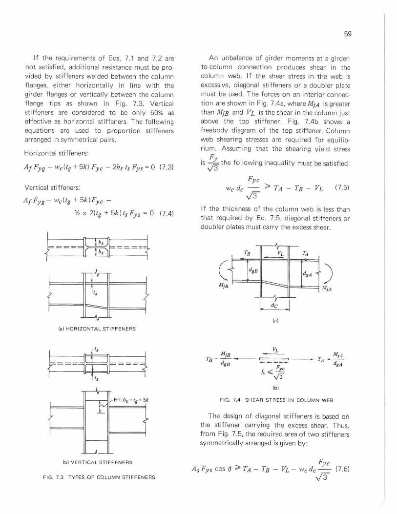
If the requi rements of Eqs. 7.1 and 7.2 are not satisfied, additional resistance must be provided by st iffeners welded between the column f langes, either horizonta lly in line with the gi rder flanges or vert ical ly between the co lumn flange t ips as shown in Fig. 7.3. Vert ical stiffeners are considered to be only 50% as effective as horizontal stiffeners. The fol lowing equations are used to proportion stiffeners arranged in symmetrical pairs.
Horizontal st iffeners:
A f Fy g - We(lg + 5k) Fye - 2bs Is Fys = 0 (7.3)
Vertica l sti ffeners:
Af Fyg - we( lg + 5k )Fy e -
y, x 2( lg + 5k) Is Fys = 0 (7.4)
~====ffi=====f j
j v
:> Its ?
-, v
lal HOR IZONTAL STIFF ENERS
.J ,
t Eff.bs = tg + 5k
7 ?
j
Ibl VE RTICAL STI FFENERS
F IG. 7.3 TY PES OF COLUM N ST IFFENERS
59
An unbalance of girder moments at a girderto-column connection produces shear in the column web. If the shear st ress in the web is excessive, diagonal stiffeners or a doubler plate must be used. The forces on an interior connect ion are shown in Fig. 7.4a, where MiA is greater than MiS and VL is the shear in the column just above the top st iffener. Fig. 7.4b shows a f reebody diagram of the top stiffener. Column web shearing stresses are required for equ ilibrium. Assuming that the sheari ng yield stress
F is vS- the fol lowing inequa li ty must be sat isfied:
Fy e We de -- ;;, TA - TS - VL
..[3 (7.5)
If the thickness of t he column web is less than that required by Eq. 7.5, diagonal st iffeners or doubler plates must carry the excess shear.
TB h TA
( ~ dg B dgA ~ )
y I. de
lal
F IG. 7.4 SH EAR ST RESS IN CO LUMN WEB
The design of diagonal stiffeners is based on the sti f fener carryi ng t he excess shear. Thus, from Fig. 7.5, the required area of two sti ffeners symmetrically arranged is given by:
As Fys cos e ;;, TA - TS -Fye
VL - We de--\/3
(7.6)
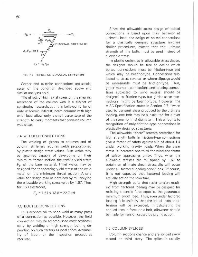
60
FLG. 7.5 FORCES ON OIAGONAL STIFFENERS
Corner and exterior connections are special cases of the condition described above and similar analyses hold .
The effect of high ax ial stress on the shearing resistance of the column web is a subject of continuing research, but it is believed to be of only academic interest; beam-columns with high axia l load allow only a smal l percentage of the strength to carry moments t hat produce column web shear.
7.4 WELDED CONNECTIONS
The welding of girders to columns and of co lumn stiffeners requires welds proportioned by plastic design stress va lues. Butt we lds may be assumed capable of developing on their min imum throat section the tensile yield stress Fy of the base mater ial. Fillet welds may be designed for the shearing yield stress of the we ld metal on the minimum throat section. A safe value for design may be obtained by multiplying the allowable working stress value by 1.67. Thus for E60 electrodes,
Fy = 1.67 x 13.6 = 22.7 ksi
7.5 BOLTED CONNECTIONS
It is economical to shop weld as many parts of a connection as possib le. However, the field connection may be accomplished most economical ly by welding or high strength bolting, depending on such factors as local codes, availab ility of labor, or the inspection procedures required .
Since the allowable stress design of bolted connections is based upon their behavior at ultimate load, the design of bo lted connections for a plast ically designed structure involves simi lar procedures, except that the ult imate strength of the bolts must be used instead of allowable stress.
In plastic design, as in al lowable stress design, the designer should be free to decide which bolted connections must be friction-type and which may be bearing-type. Connections subjected to stress reversal or where sl ippage would be undesirable must be friction-type. Thus, girder moment connections and bracing connect ions subjected to w ind reversal should be designed as friction-type, but girder shear connections might be bearing-type. However, the AISC Specification states in Section 2.7, "when used to transmit shear produced by the ult imate loading, one bolt may be substituted for a rivet of the same nominal diameter". This amounts to recognition of on ly friction-type connections in plastically designed structures.
The allowab le "shear" stresses prescribed for high strength bo lts in friction-type connect ions give a factor of safety against slip of about 1.4 under working gravity loads. When the shear stress is increased one-third for w ind, the factor of safety approaches unity. Thus, when the al lowable stresses are mult iplied by 1.67 to obtain an ultimate shear stress, slip will occur under all factored loading conditions. Of course, it is not expected that factored load ing will actually act on the structure.
High strength bolts that resist tension resulting from factored loading may be designed for resisting a tensi Ie force equal to the guaranteed minimum proof load. Thus, even under factored load ing it is un likely that the initial installat ion tension wi ll be exceeded. In ca lculating the applied tensile force on a bolt, allowance should be made for tension caused by pry ing action.
7.6 COLUMN SPLICES
Column sections change and are spl iced every second or third story. The sp lice is usua lly
placed about two feet above the floor level. The sp lice must be designed for:
1. An axial compressive force result ing from the factored dead and live load. (F=17)
2. Axial compression force plus shear and moment caused by wind acting in conjunction with dead and live load. (F = 13)
3. Axial tensile force plus shear and moment when tension occu rs under a condition of full factored wind load combined with 75% of the factored dead load, and no live load. (F. = 1.3)
According to the A ISC Specification, in tier build ings lQOOIo of the axial compression force may be transmitted from one column section to the next by bearing, provided that both sections are milled. Partia l penetration groove welds having no root open ing may be used to join column flanges when the stress to be transferred will perm it them.
When co lumns of the same nominal depth are spl iced, full bearing is possible because the inside-of-flange dimension is the same for all weights. The weld or bolts and t he splice material serve only to hold all parts secure ly in place. I f the lower column is much deeper than the upper one, it is necessary to weld stiffeners on the inside of the lower column fl ange to provide an adequate bearing surface. Alternative solutions are to provide a bearing butt plate on the lower co lumn or to develop the strength of fills fastened on the outside of the flanges of the upper co lumn.
Horizontal shear forces are resisted by plates on both sides of the column webs extending across the jOint of the upper and lower column sections. If a butt plate is used, shear is resisted by bolts connecting web angles to the butt plate. Web plates or angles also aid erection by holding the column sect ions in line during f ie ld welding.
61
Tension resulting f rom significant moments at column splices is transmitted by full penetration flange we lds or by splice plates fillet welded or bolted to the flanges. For typical details see Ref. 9.
7.7 BRACING CONNECTIONS
Diagonal bracing is often laid out with its centerline intersecting the center lines of girders and columns as for a pin connected truss. This arrangement usually permits the horizontal component of the bracing force to be transmitted into the girder flange and the vert ical component into the column flange-a direct transfer into the logical resisting member without introducing a shear into t he other. However, other considerations often cause deviations from this ideal arrangement. Welded girder-to-column connections, because of their simpl icity of detail, facili tate the connecting of bracing.
Bracing connection details depend upon the type of member used for the bracing, i.e., rods, pairs of angles, H-section, or tubes like the pipe used in the design example. Gusseted connections consisting of plates and angles, or tees shop welded to the brace may be used. The high strength bolt is ideally su ited for mak ing the field connection because of its ability to pull up the draw in t he brace. Tubes may be connected to gusset plates by slott ing the tube, and fil let we lding the tube to the plate, or full penetration butt welds join ing tubes to end plates provide an excellent and simple connection.
InK-bracing two diagonals join one another at midspan of the girder. Research 10 has shown that a stronger connection is developed if the centerlines of the pipe braces intersect before reaching the girder centerline, i.e., have a negative eccentricity. This geometric arrangement causes a partial intersection of the pipes and a more direct balancing of the vertical components of the bracing forces.

62
63
CHAPTER 8
Design Example
This chapter includes plastic design ca lculations for the braced multi-story building in Fig. 8.1. Chapters 4 to 7 describe the design steps which are indexed in Table 8.1. A design summary of main member sizes is given in Fig. 8.2.
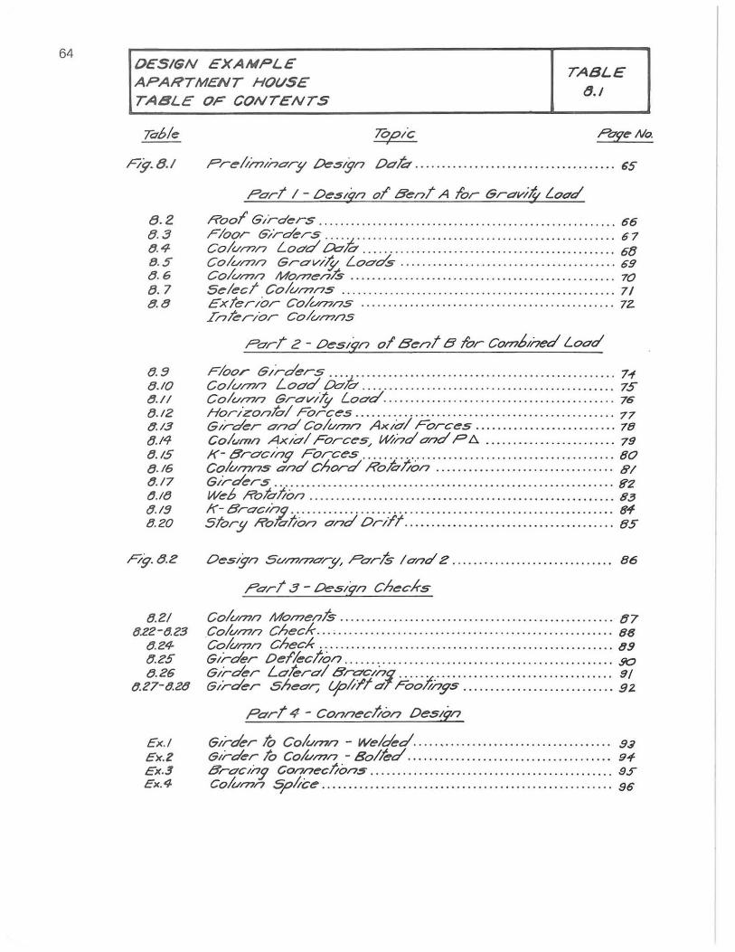
64 O€SIGN EXAIrIPL£ APAHTM€NT HOVSE TABLE OF CONTENTS
TABLE 8./
F/g.8./
8 . 2 B. 3 8. 4-8.5 B. G 8.7 8.8
8.fJ 8.10 8.// tJ.l2 t/./3 8.14-8.15 8./6 8.17 8.18 8.1fJ B.20
F/g.8.e
8.2/ 8.22-8.23
tJ.24-tJ.zs tJ.Z6
{!.Z7-8.28
Topic >
Pre/;/nlnO'r!! Oes;gn Ddt:? ........... . . .......... ... . ......... 65
Pdrt / - Deslqn 01 8ent A lor ISrdv;4- Load
Roof Girders . .... . .... .. ........................................... 66 Floor GXrders . . .. '.t ... . . . ....... ...... . .............. ........ ...... 67 Col(//7)/7 LOdd 00/0' . .............. ....... .. . .. . . ................ .. 68 Colu/7?/7 GrO'v/1: Loads ............ .... .......... ..... . ... . .. . . 69 CO/{/l77n MO/7?enl.S... ......... .... ....... ...... .... ... . ... .. .. ..... 70 Select CO/U/7?/7S ... . .......... .... .... .................... .. .... ... 7/ Exter/or CO/C//71/7S .................... ..... ........ ... ... .. . ... .. 72-.L/7krior CO/U/7?/7S
Pari,;: - Deslq/7 01 Be/7t B wr COl77b,i7ed Load
Floor Girders .... .;. .. .... ... ... .... ............. ... ............ .. .. 7-f Colu/7?/7 Load 00/0' . ... ..... ... .............. . ....... ...... .... .. . 75 Col(//7'Jn GrO'vl1-' Load .......... . ... .. ....... .. . ............. .... 76 Horizonlo/ Forces .. . .. . .. ..... .. ... ..... ............. ......... ... 77 Girder and CO/(/l77n Axio/ Forces ......... . .... . ........... 78 Col<.m/'l AXldl Forces, iMnd and PA ........................ 79 K- 8rO'c'/7g Forces ......... . .. . ........ . .. . ...... . . . . ... .... . . ... 80 Colvl77ns 0'/701 Chord /('%//on ................................. 81 Girders ... . . . ..... . .. . ...................... .... ... . . . .. . ... ....... .. . Ef2 Web Rotol/on .................... ......... ................... ......... 83 K- BrO'clnq .. .............. .. .... .. . .. . . . . ....... .. .. . ...... . ...... .. . . 8'1 Stor!! Rohl/cm 0/70' On/t ............. .... . .......... ..... ...... 85
Oeslgn SUl77a?O'ry, PO'rh / and e . . . .. .. .... .... ..... . ... . .. ... 86
PO'rt.3 - Oeslfn Checks
CO/(/l77n MOl77enh . . . . ........... . ..... .. . .. .... ... ..... ........ .. ... B7 CO/(/I77/7 Check ... , ....................................... . ........... 88 Cohl77/7 Check .......................... .. ........... . ........ .... ... 89 Girder Dellec!;o/7 ......................... . . ... .. . ..... . .. .. .... .. . 50 Girder LO'terO'/8roc'nl .. .. · :t ........... .... .. .. .............. . 9/ Girder shear; qo/i~t a'. Foo///7ys ............................ 92
Part 4 - Connec!;o/7 Desl?/7
Ex.! Girder 10 Co/wnn - Wekkd.. .. ........ ...... ........... . ....... 93 ex.Z ISlrder to Co/t.//77/7 - Bo/ted ... ...... .. .. . ...... ..... .... .. .. .. ... 9+ £x.3 8rO'c,ny Connecl/ons ........... ........ .......... ... . . . . ...... ... 9~ ex. 4- CO/(/l77n sp/;ce .. .............. ...... ... ......... ...... .. .......... .. 96
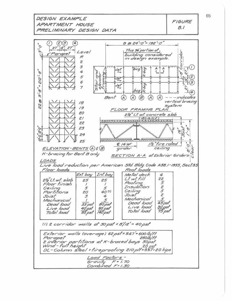
OeSIGN EXAMPLE APARTMENT HO(/SE PRELIMINARY OESIGN OATA
-: ,ParapeT
"./ "./ "./ "./
Ib '-,/ "./
I "./ "./ ,
~ "./ "./ ~ "-./ "-./ \)
~ , , ,
'" , 0)
@, '\/ , /
~ "./ ". / "./ "./ l"./ "./ "./ '\/ "'-/ "'-/
~ \/ \/ ~=-1V\ /\~ ,
2
3 4
.5 6
7
18 19
20 21 22
Z3
24
25
ELEVA TION-B'ENTS @t@ K-6racin910r BenT B onll
LOADS
I'
SECTION A-A
FIGf./RE tJ.I
Lt've load redf./clion per Arneric4r7 std Bldg. Co",*" A58.1-1955, Sect.'!. Floor loads ROOT 100'ds
Ext bO'!I 2Y./Lf. wI slab 25 Floor f/r7/~h 1 Ce;it~ 5 Parr,: Ions 20 JO/sT 3 Mechanical 1
DeO'd 100'd 55,1751 Live 100'd ~: TolblloO'd B. p5f
IntoO'j/ 25
1 .5
40(1) 4 5
6'0,1751' ~51'
I 'P51
MehldecA- 4 Lt wI /,//1 22 Roor"n~ 5' Insf.//o-,/on 2 ceiitng 5 JO/sT 2 MechO'n/col 5
Dead load 405psf Live load ~I To/CtlloO'd 75',1751'
ExTerior walls (ewerag.e) 62psl'x5.67'-600lb/1'1 p~~d 2~#~ 2 InTerior ppr·I;lions 01 K-brr;ced 6ays 50;051" W/nd - /'u/f he/9;hT 20 psI DL - Colu177n steel'" 1/;-"";oroo//;'.9' Zlopl/'xB.67':Z.0 A-jos
Load FaclOrs-GravllSt F - I . 70 C0177bined F: 1.30
65
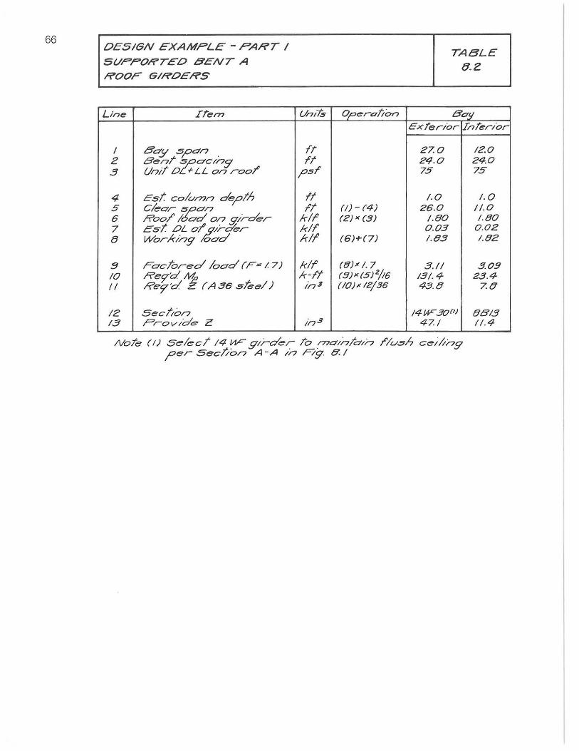
66 OESIGN EXAMPLE - PART I S(/PPORTED BENT A ROOF GIRDERS
Line ITem
/ Bay span . 2 Ben!" :!:.aclng 3 Unit 0. I- LL on rooT
4 Est col<//77n depth 5 Clear ~an 6 Roof' I< ad 0/7 girder 7 Est OL o~;-d'er t3 Working oad
~ Faclored load (F= I 7) /0
" Rec;'d M Rec;"d E (A 36 steel)
/2 SecTion /3 ?rovlde Z
(/nils
fi fT
psf
ft It
kll kli kiT
kif k-fT In 3
117 3
OperaJ/o,.,
(/J - (4) (2) x (3)
(6)-1-(7)
(8)"1. 7 (9)"(5)2/16 (10),,12/36
TABLE Q.Z
Balj ExTerior IInier/or
27.0 /2.0 24.0 24.0 75 75
1.0 1.0 26.0 1/.0
1.80 /.80 0.03 0.02 1.83 1.82
3.11 30!! /31.4- 23.4-43.8 7.8
/4UF30(') 80'/3 47.1 1/.4
NoTe (I) selec/ /4 ~ girder To r7"JO'ln/a/n /'Iush cei/;ng per Secl/on A-A In Ag. 8.1
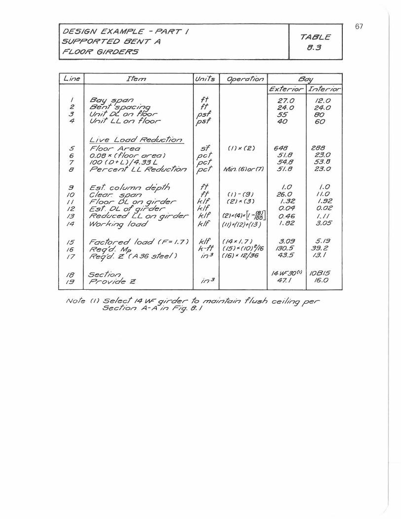
DESIGN EXAMPLE - PART I
S(/PPORTED B'ENT A
FLOOR GIROERS
Line ITem
I BO!j SpO/7 2 Bent :ZC::0Clng 3 (//7lt 0. on /Ioor 4 (//""JlI' LL on I'loor
LI've Load Reduclion 5 Floor Area 6 0.00 x (floor area) 7 100 (O+L)/4.33 L 8 Percent LL Reducl/on
9 Est colu/77n depth /0 clear fJ'f0n II Floor L on gIrder /2 Esl'. OL 01' gIrder 13 Reduced LL on gIrder 14 Workng load
IS Facl'ored lood (F~ 1. 7) /6 Re<j''d. Mp 17 Re9''d. Z (A 36 sleel)
/8 Seclion 19 ProvIde Z
Un/ts
ft ft
psI psf
sf pet pet pet
It ff
kif kif kif kif
kif k-f'/ in 3
in 3
Operation
(!)x(2)
Mh. (610r(7)
(f 1- (9) (2)"(31
(2}«4IX~ _(81J 100
(11)t(12)t/l3 )
(!4x 1. 7) (IS)' (10)'/16 ((61< 12/36
TABLE
U.3
Bo!! Exterior InterIor
27.0 12.0 24.0 24.0 55 80 40 60
648 Z88 51.8 23.0 54.8 53.e 5/.8 23.0
1.0 1.0 26.0 11.0
1.32 1.92 0.04 O.OZ 0.46 1,/ I 1. 02 3.05
3 .0!'! 5.19 /30.5 39.Z 43.5 13.1
14W'.30M 10B15 47.1 16.0
Note (/) select /4 VIF girder 10 /77o/n/oln I'lush celltng per Secl/on A-A in F'tg. 8. I
67
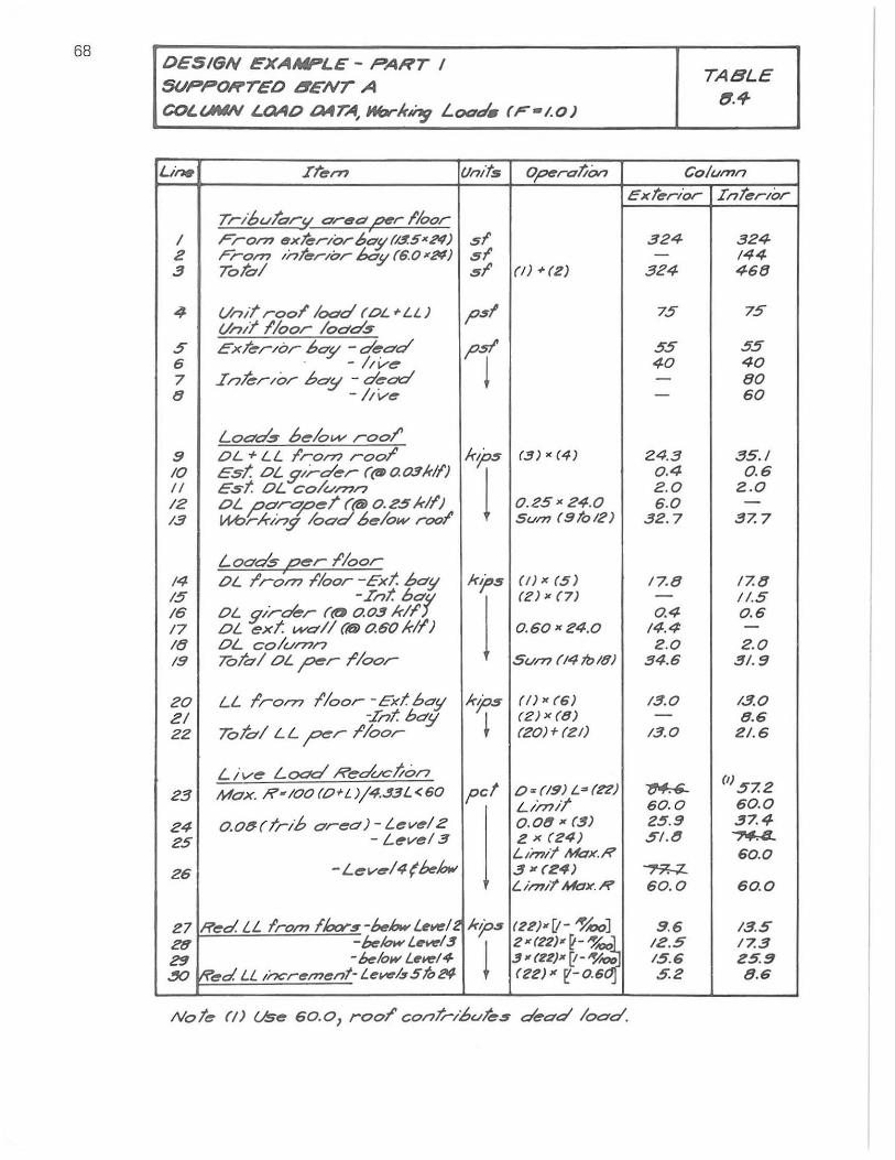
68 DESIGN EXAMPLE - PART I SUPPORTED 8ENT A
COl.tMN I.OAO a4TA, HtrK~ Load. (F"-1.0)
Li~ Il"ern tlmts OperatiOn
Tri6tJl"ar,/ ar~ct ~ I'loor I Fron? exTerlorb'ay f/4SK ;i"I) 51 2 Fron? InTerIOr 60y (6.0"N) 51 3 Tolal 51' (I) 01-(2)
4- (/nlT rool' 1000d (OL .. LL ) psI (/nlll'loor 10dds
.5 exT~rlor bo-y -dedd psi' G . - /;V~
t 7 Inkrlor bO'!I - d~ctd 8 -kve
LOdds b~/ovv rool' 9 OL + LL I'ron? roor
T (3)" (4)
10 est. OL!prder ((l»a0.3lr1l) II Esf OL co/v/71n 12 oL p'dr<:p~1" ("(Ii) 0.25MI') 0.25"24.0 /3 ItI--brk'ny load 6elow rool' $(/171 (9 to /2 )
Loads p~r I'loor 14 OL I'rdm /'Ioor -Ext. bay kit's (lJx (5) 15 -Int. bay
j on K (7)
16 OL gir~r (tJ 0.03 kll' /7 OL ext. vv~dl (i6) 0.60 kll') 0.60 K24.0 /8 OL coltJ/71/7 19 ToTal OL per I'loor SUI?? f /4 Ib /8)
20 LL 1',0/71 /'Ioor -Ext boy kp5 (I)K{6) ZI :In! OefY ~
(2) x (8)
22 Toldl LL F' I'loor (20)+(21)
Liv~ Load R e dvc//o/7 23 Max. ,R'100(O'L)/4.33L<60 pc! O=(19)L~(n)
j LirTJ/!
24 0.08 (Iri6 O'r~o) - Level2 0.08 K (3) 25 - L~vel3 2 x (24)
Llmtl~x.R
26 -L~v~/4{klow 3 K(24) Lin"t~x.R
27 Red. LL Irol71 floors-khwLeve/2 ktps (22)-'I!- ~A:>OJ 2t1 -k/O..,L~/3
! 2-(22)-~-' 29 -""low Lew:14 3 - (ZZ)" [I-~-.XJ If'~d LL Incrl!tl71ent- L,.~/.s 510 2'9 (22)" ~-0.6
TABLE (I.If
Col(Jl71n
exterIor InterIor
324 324 - 144
324 468
75 75
55 55 40 40 - 80 - 60
Z4.3 35./ 0.4 0.6 2.0 Z.O 6 .0 -
32.7 37.7
17.8 17.8 - 11.5 0.4 0 .6
14.4 -2.0 2.0
34.6 3/.9
/3.0 1.3.0 - B.6
13.0 2/. 6
~ (I) 57.2 60.0 60.0 25.9 37.4 51.t! ~
60.0 ~ 60.0 60.0
9 .6 /3.5 12.5 /7.3 15.6 25.9 5.2 8.6
Not~ (j) Us~ 60.0, rool' con/;-ibuT~s dead load.
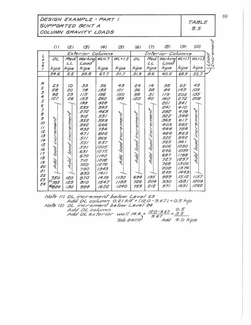
DESIGN EXAMPLE - PART I
SUPPORTED BENT A
COLUMN GRAVITY LOADS
TABLE
8 .5
(/) (2) (.3) (4) (5) (6) (7) (8) (B) (10)
L Extt:rlor Columns InTt:r/or Colun?r7s
e OL Red. Work:j;s WLxl. 7 WL"1.3 OL Rt:d. work,';J WLxl7 WLx l.3 v LL Loa. L-L Loa e
kips ktPs kips kips kips ktPs kips kps lops kps I 34.6 5.2 39.8 67. 7 5/.7 3/.9 8.6 40.5 68.9 52. 7
~ 23 10 33 56 43 24 14 38 65 49 2 58 20 75 /33 10/ 56 20' 0'4 143 /09 3 92 23 //5 /96 /50 88 3/ 119 202 /55 4 /27 26 /53 260 /99 /20 40 /60 272 208 .5 6 -r-- -- /93 328
J -- - 20/ 34/ -r--
7 233 395
1.,. 24/ 4/0
~ (J \ 272 463 "-~
292 479
9 ..... ;1/2 53/ ~ ~ 322 548 " 10 ~ ~ 352 599 ~ ~
363 617
~ 392 666 ~ 403 685 II II 432 734 ~ ~ 444 754 12 " ~ 471 802
\j 484 Q23
13 ~ \j
.~ .~ .~ .~ 5// 869 .~ " 525 892
1+ ,
% 15 .~
~ 55/ 937 ~ ) ~ 565 .96/
16 g 59/ /005 ~ ~ 606 /0.30
~ ~I 63/ /072 ~ 646 /099
17 ~ 670 //40 ~ ~ ~ 687 1/68 ~ I(J ~ ~I 710 /200' 727 /237
19
i 750 /276 " '<: " 768 /306 " 20 ~ 790 /343 80e /374-ZI -c... 830 /4// - -'-.... -'-. 8';19 /443 -22 23 750 /20 870 /479 1/.30 694 /95 889 /5/2 1/57
Z4 (/17(J5 /25 9/0 /547 //e3 726 204 930 /58/ /Z09
~)824 /30 354- 1622 /240 759 212 371 /65/ /262
Noh (I) OL incrernea/ be/ow- Leve/ 23 Add OL cO/U/77/7 0.21 kiT' x (;2.0-9.67) =0.5 kp
Noh (2) OL /l7crernel7/6elovv Level 24-Add OL. CO/Ur/7/7 120-967 0 . 5 Add 0", ex/er/or vvO'// /4.4- x 8.67 = 3.5
7&.6. ff.4(17} Add 4.0 ktps
'\)~ gu --.J~ V
69
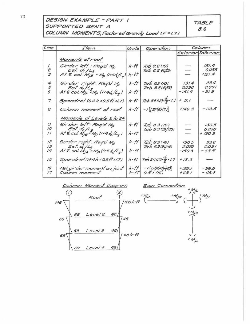
70 OESIGN EXAMPLE - PART / SVPPORTED BENT A
TA8LE 8.6
COLUMN MOMENT5,FactoredGrovi/fl Lcxrd (F-I.7)
Line
1 2 3
4 5" 6
7
8
5}
10 II
12 13 14
/5
16 17
ITem Unit?s Opt:!ratfo,., Colvn?,., ExTerior InTerior
MOn?enlS ot rOOT
Girder leTt: Re9"i::! ~ If-If lOb 8.2 (to) - 131.4 EsT. dc/L~ 70"6 8. 2 r4yr5/ - 0.038
A f ~ col ~'a : ~ (Ir44/L.5 k-It - +151.4
Girder il!hr. Refi::! A-fo k-It TO-b 8.2(10) 131.4 23.4 est a; L$ Tab tl2r4yrS) 0.0.58 0.091
Aft col :tA ~~ (1+444.1) kit -151.4 - 31. !I
Spandrel (6.0/,-x0.51Ix/. 7) k-If hI> ~4 (12)''4. I . 7 + 5./ -Colv/77n ;77on7enT ct rooT k·11 - / [r.5)1'6>,m] +146.3 -119.5
MO/]?enh aT LevekT 2,0 E!4
G//-cler leTT: Re9"i::! ~ k-II ?db 8.3 (16) - 130.5 EsT. dc/Ls TcTb 8..5 (5)/(!O) - 0.038
At!f col ~s: A1> (1+44/L~ ) k-fl - + 150.3
G/i-der r;:J.ht RC9"i::! A1> kit hb 8.3(6) 130.5 35.2 Est. ~/L$ Tab 8.3(9ij(I(l) 0.038 0.091
Atl'f co/~:. = "'10 (Ir4d,/L5) k-If -150.3 -53.5.
Spandrel(I4.4/'-xo.51IxI. 7 ) kit "-hb If.4(17)xt- x 1.7 + 12.2 -
Net9,r-der mOn?enT on j:)/nT k-It -I [(1#4N5)] +138./ -.96.8 Co/v;77n rno/77enT k-// 0.5 x (t6) 7- 6.9. I - 48.4
Column Moment O/ogrorn S/qn ConvenJ/on
(jJ (2) ~l. Y Rool Y '1I'!i:. "lI1{a ( + ~ ~A
146
69
----=-=--- Izoldt (--- ) )
69 Level2
69 Level.5
65 Level4. 48
'-" +MjlJ
'"
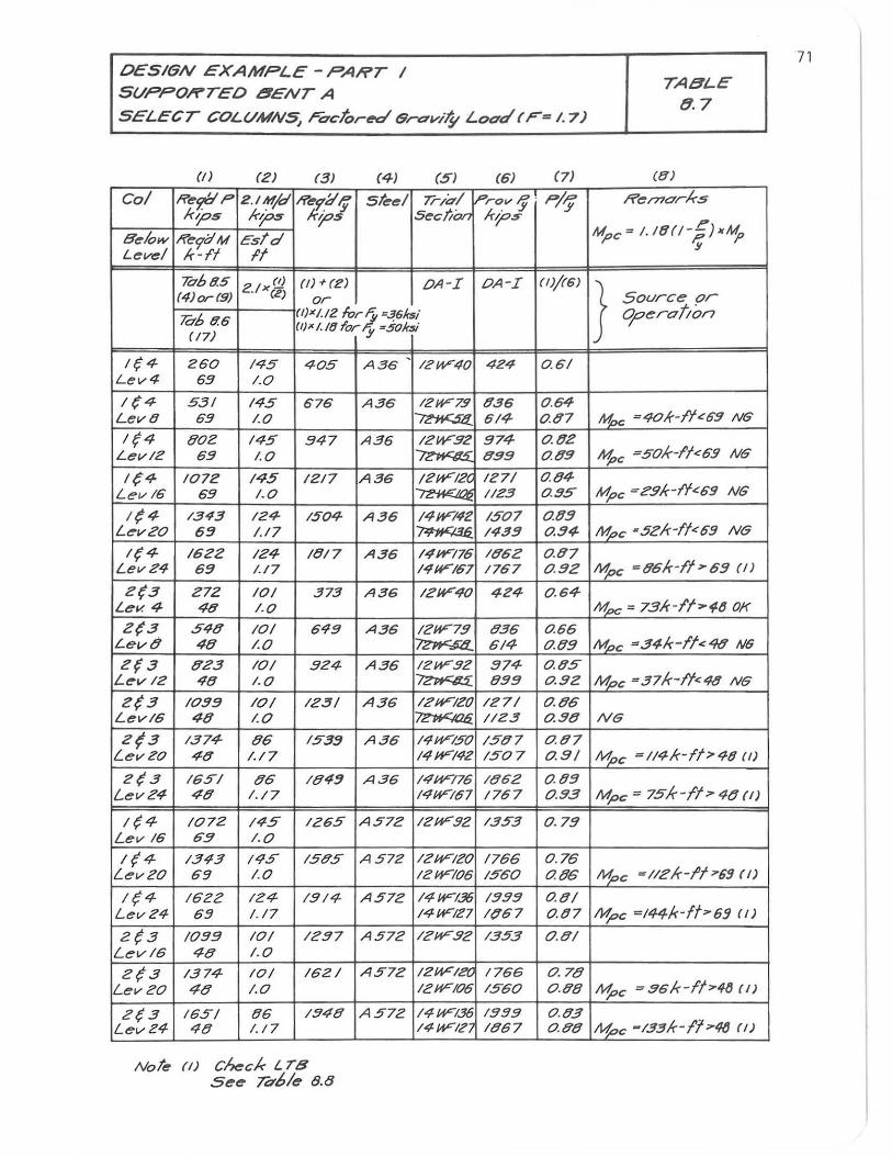
OESI6N EXAMPLE - PART I SVPPORTEO 8ENT A
SELECT COLVMN5, rcc.jor~ 6raviIY Load (F= 1.7)
(/) (2) (3) (41 (5) (61 (71
Col R~FP 2.IMjd 1i'~f.::I t; st~~1 7hd/ Prov If' p/'f kips kips Kt;:>S s~c!'iOn kt;:>,s
e~/ow ff~9'CI M Estd Level k-It It
T068.5 (I) (/) + (Z) OA-I (4)or(9) Z.l x (2)
or
&68.6 (I)X/'/2 furi :~61f~i (/7)
(I)X 1.l1! for y :501r3i
1(4 260. 1<15 <10.5 -A56 IZW'40 Lev4 65 1.0
1(4 55/ 145 676 A36 IZW'7!! Lev8 65 1.0 ~ 1(4 802 145 !J47 A36 12W'.!12
LevlZ 69 1.0 I/~"--"""
/(4 1072 145 1217 A36 12W'12C Levl6 69 1.0
/(4 13"13 124 1504- A35 141¥7"1Z LevZO 63 1.17 ~ 1(4 1522 IZ4 1017 A35 14W'176
LevZ4 53 1.17 141F157
2(3 272 10/ 373 A56 121F40 Lev. 4 48 1.0
2{3 548 10/ 649 A56 121F7.9 Leva 48 /.0 ~ 2{3 823 101 .924 A36 IZW'!!Z
Lev 12 40 1.0. ~
2(3 1059 10/ 123/ A36 12W'IZO Levl6 40 1.0 ~
Z{3 1374 86 153:1 A35 14W'150 LevZo 40 1./7 14W'142
2(3 165/ 86 184:1 A36 14W776 Levi?4 48 1./7 14W'167
1(4 1072 145 1265 A 572 12UF92 Lev 16 6.!1 1.0
If4 1343 1-95 1585 A 572 IZW'Ii?o. LevZO 69 1.0 12UFIo.5
If4 1622 124 1514 A 572 14W'1.3fj Lev24 65 1.17 14W'127
2{3 /059 10/ IZ57 A 572 IZW'.9i? Levl6 40 1.0
Z(3 1374 10/ 1621 A57Z 12UFIZO LevZO 48 1.0 IZW'I06
Z{3 165/ 96 1548 A57Z 14W'136 Levi?4 48 1.17 14W'IZ,
Not~ (/) check L TB See To'61e 8.8
OA-I (1)/(6)
4Z4 0.61
936 0.64 614 0.97
!J74 0.02 8.!19 0.99
IZ71 0.84-1123 0.95
1507 0.05 1435 0.54-
186Z 0.07 1767 0.92
424 0.64
836 0.55 6/4 o.Og
!J74 0.05 859 0..92
127/ 0.86 1123 0..98
1587 0.87 1507 0.9/
1862 0.89 1767 0.53
1353 0.7g
1766 0.76 1560 0.86
1555 0.81 1(167 0.97
1353 0.8/
1766 0.78 1560 0.98
1555 0.93 1867 0.88
TABLE 8.7
(5)
R~r71ark5
Mpc = I.IOO-f) xkfo y
} Source or Operation
Mpc =40/r-f'f<:6!! NG
I11>c =50k-l'f<6!! NG
Mpc Z.!1k-lt<:59 NG
Mpc ·5zk-ff<69 N6
~c =06/r-ff>'63 (I)
M,oc = 73/r-lf>"'6 OK
Mpc =34/r-fl<4Q N6
Mpc =37k-/t<48 NG
N6
~c =114/r-fl>4tl (I)
Mpc = 75k-ll;> 48 (I)
Mpc =llz/r-fl7'65 (I)
Mpc =/44Ir-ft7'6!J II)
~c =.!16/r-fl>41J (I)
~c -133/r-lt>4Q (I)
71
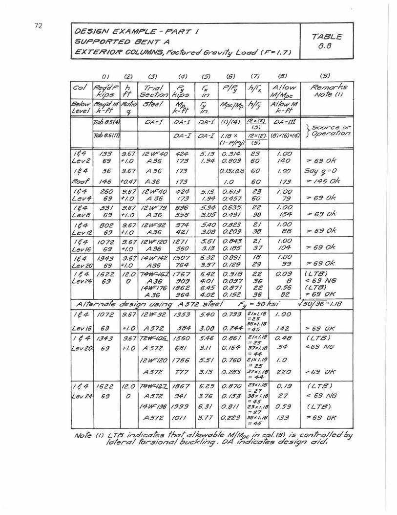
72 OES/6N EXAMPLE-PANr /
SVPPOHrEO 8ENr A TABLE
(J.8 EXTeRIOR' COL.VMN5, Foetoreo" 6rovit!l LODo" (F- 1.7)
0) (2) (3) (4) (5) (6) (7) (81 (:/)
Col iR"'9'OI ,.,. h rriO'/ ":Y 1; P/ry hj~ Allow Re/71O'rA-s kl;05 f't Sect/on lop., In M/"1oc Nohm
&Iow R"'9'U'M Kat" steel M. /j M,oc/tIfo h/f AlhwM Level k-f'f '1 lr-'1t In. k-If
~68.5(4. OA-I OA-I OA-I (1)/(4) 12)((2) OA -.llI (.!J ) }sourc~ or
706 8.6(1) OA-I OA-I 1.18 " IZX(l?!- (8) ' (6)«4) OperO't/on
rt-p/ry) (5)
1(4 133 9.67 IZW40. 424- 5.13 0..3/4 Z3 1.0.0 Lev2 69 +1.0. A36 173 /.94- 0.809 60. (40. ~ 6!! ok
1(4 56 9.67 A36 173 D.l3L(7.15 60 1.00 Soy '1=0
Rool' 14-6 +0.47 A36 173 1.0 60 173 ,.. 14-6 Ok
1(4- 260 957 12W40. 4-24- 5.13 0.613 23 1.00 Lev-l 65 +/.O A36 173 1.94 0.:457 60. 75 ,.. 69 Ok
1(4- .53/ 9.67 12W79 836 5.34- 0.635 22 1.00 Lev8 6!! +1.0. A36 358 3.05 0..43/ 38 154- "'6:/ Ok
1(4 802 9.67 IZW92 374- 5.40. 0.823 2/ 1.0.0
Levl2 69 +/.O A36 42/ 3.08 0.20.9 38 t!t! ",69 Ok
1{4 10.72 9.67 12WIZo. 127/ 5.5/ 0 .843 2/ 1.0.0
Lev/6 69 +/.0. A35 560 3./3 0.185 37 /04- ".. 69 ok
/(4 1343 3 .67 1414'142 150.7 6 .32 0.89/ It! 1.00.
Lev20 59 +1.0. A36 764- 3.97 0.129 29 39 "'68 Ok
1(4- 1622 12.0. I~,£., 1767 6.42 0.91t! 22 0.09 (LTB) Lev24 6!! 0 A3; 30.9 4.0./ 0.057 36 8 <: 5!! NG
/4W176 1852 6 .45 0.871 Z2 0 .56 (LTB) A36 964- 4.0Z 0.152 36 8Z ,. 59 OK
AlternO'te des/7n t/sln 7 A 572 3ke/ F: =501<-5/ 1150./36-1.18
1(4- /0.72 3 .67 12W9Z 1353 5.40 0.. 733 ZJx/IB 1.0.0 =25
Lt!!v 16 69 +/.0 A57Z .ff84- 3.08 381(/.18
0.244- =45 142 "690.11'
1(4- 1343 9.67 ~ 1560 5.46 0..86/ 2/)(/.18 0.48 (LTB) =25
L.t!!v 20. 69 +1. 0 A 572 681 3.11 0..164- 37x/./8 54- ""6!! NG =44-
IZW-12D 1766 5..ff/ 0.760. Z/X /./6 1. 0 =z5
A 572 777 3.13 0 .28.3 37x/.(8 220 "69 OK =44-
1(4- 1622 IZ.O ~ 1867 6.2!! 0.870. ZJK/./8 0.19 (LTB) = Z7
Levl?4 6!! 0 A 572 34/ 3. 76 0,1.ff3 36KI./8 Z7 .: 69 NG =45
14-W136 1399 6.3/ 0 . 811 23x/./8 0..59 (LTB) =Z7
A572 lOll 3. 77 0.2Z3 "81< I. It! 133 "'69 OK =45
Nok (I) LTB Ino'l'cerk5 thO't erllower6/e M/~c 1/7 col (0) is cOI7/rolle'd 6!1 lerterel JOr3/onerl bvckl/ng . 041ndtceks de.s&,n did
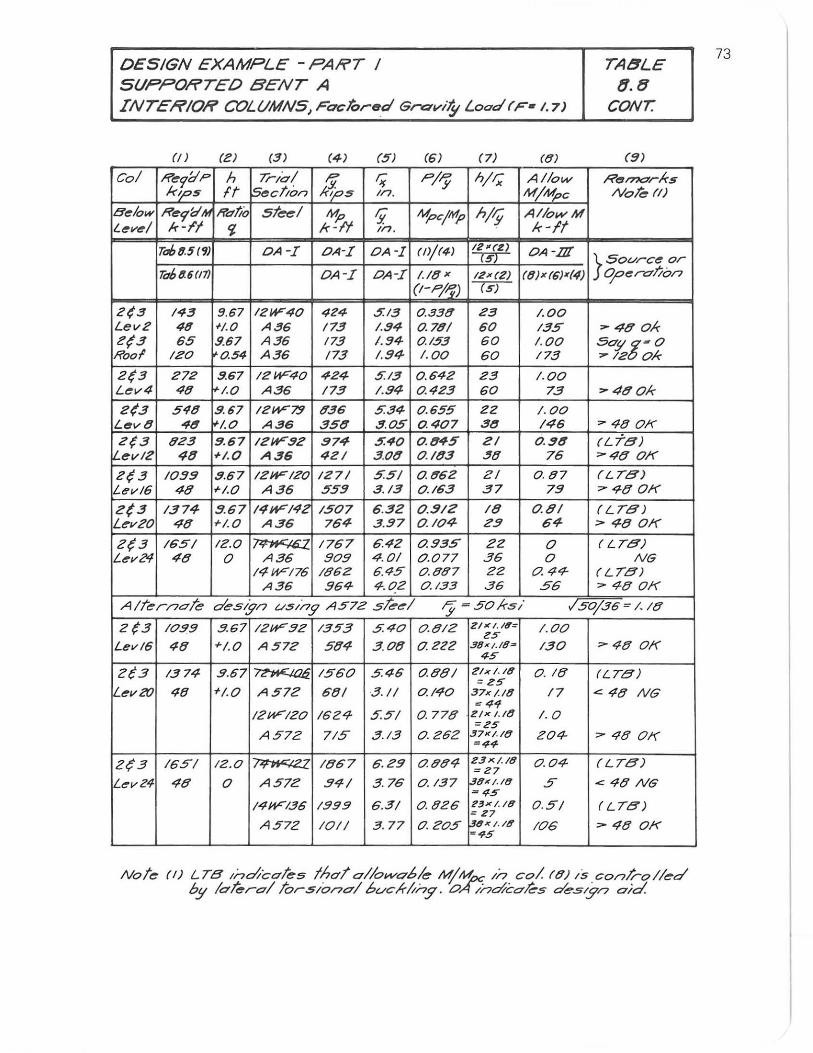
DESIGN EXAMPLE - PAIi'T I SUPPORTED BENT A INTER/Oli' COLUMNS,Facfo'-~d GravIty Load(F- /.7)
(n (e) (3) (4) (5) (5) (7) (8)
col R~7'd'P h T'-IO'I I? ~ PIPy hit; A/low kips It !sectIon H"fos In. M/~~
B~/ow R~9i:1lH Heft/a steel M- y. MpcjMp hi;; A//owM t.~v~1 k-I"I Ii k'!'/t In. k-It
r068.5 (7) OA-I OkI OA-I (I}/(4) 12 111 ('2) OA -.OJ csr 7i16 (f.6 (17) OkI okI 1.18 " 12x(2) (8) x (6)x(4)
(I-pi;;) (S)
2(3 143 S.67 12W40 424 5.13 0.338 e3 1.00 Lev2 48 +1.0 A35 173 1.94 0.78/ 60 135 Z(3 65 9.67 A36 173 1.!l4- 0.153 60 1.00 Hoof leo 0.54 A36 173 1.94 1.00 60 173
2(3 e7e 9.67 IZW40 4e4 5.13 0.64Z e3 1.00 L~v4 48 1.0 A36 173 I .S4 0.423 60 73
2(3 5'18 9.67 leW7!1 836 5.34- 0..655 22 1.0.0 L .. v8 48 1.0. A36 358 .!!. 0.5 040.7 38 /46 e(3 ge3 !I. 67 leW92 974- 5.40 0.84-5 Z/ 0 .98 iL~vl2 48 +1.0 A36 4el 3.08 0.183 ~8 76
e~3 10.99 9.67 IZWIZD 127/ 55/ 0. 86e el 0..97 Levl6 48 </-1.0 A36 559 3. 13 0..163 37 79
Z(3 1374 9.67 14HFI4Z 150.7 6.32 0..91Z 18 0.8/ LevZO 48 </-1.0. A36 764 3 .97 0..10.4 Z3 64
Z{3 lli51 IZ.O ~ 1767 6.42 0.935 22 0. Lev24 48 0 A36 90.9 4.01 0..077 36 0.
14-W176 1862 6.45 0..897 ZZ 0.44-A36 964- 4 . DZ 0.1.33 36 56
TA8LE 8.8
CONT.
(!I)
R"n>o'rks NoJe. f/)
}sovrc~or 0;Oelra/;on
,.. 48 o.k SO'S' g~o. ,.. 12 o.k
,.. 480.k
7480K (CT8) 748 01<
(LT8) "'" 480.1<
(LT8) 74801<
(LT8) NG
(LT8) ,.. 48 0.1<
A/Terno-Te design vS//7g A572 steel IJ -5DHS/ 150./36 1.18
2(3 10..99 .!!. 67 12W'.92 1353 540. D.8IZ 2Ixl.18~ 1.0.0. es Levl6 48 +/.0 A57Z 584 3.0.8 o.Z22 38K/.18# 130 748 OK
4S
2(3 1374- 3.67 ~ 1560 5.46 0..88/ Zlx/./6 =25
0..18 (LT8)
I...ev2r) 48 +1.0 A57Z 68/ 3.1/ 0. I,{-D 37x /./6 17 '" 4-8 NG & 4-1
IZHFIZD 1624 5.5"/ 0..778 2/x /./tJ 1.0 =25
A57Z 715 3.13 0..Z6Z 37x/· /O 20.4- 748 OK =44
2(3 165/ 12.0. ~ 1867 6.Z!1 0.994- 23x/.18 0..0.4- (LT8) =27
LevZ4 48 0 A 572 .94/ 3.76 0. 137 39xI.l8 .5 .c 48 NG =45
14WI.36 13519 6.3/ 0.026 23xl./8 0.5/ (LTB) = Z7
A 572 101/ 3.77 0.20.5 38.JC/./8 ~45
106 ,.. 48 OK
Note (I) LTB ,r}(/;cO'te5 IhO'lo/lo_oble M/Mpc //7 col (8) /S ,conl/--o/led by lateral tors/o/7o/ 6uclr-/;ny . OA /nmcoks des".!?n a;c:I.
73
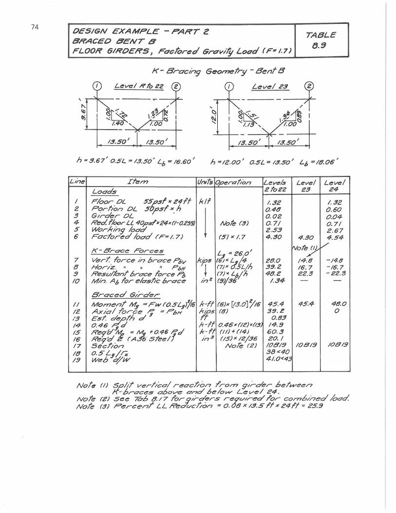
74 OESIGN EXAMPLE - PART Z BRACEO 8ENT 8 FLOOR 61ROERS, raclOred Gravi'!! Load (F· 1.7)
TABLE
B.9
K- Bracing Geornetr!l- BentB
13.50' 13.50' 13.50' /3.50'
h - 9.67' 0.5L = /3.50" Lf, = 16.60' h=/2.00' Q5L=/3.50' LD =I8.06'
LIne Ifern (/f'Hts Of"<'ra /ion Lev",& Lev",/ LOC1ci5 21022 23
I Floor DL 5~$I"24lf kif 1.32 2 Portion DL 51 1'$1 ". h
I Q4tJ
3 GIrder DL 0.02 4 Red. floor LL 40psf' ... 24k(l-aZ5!J) Noh (3) 0.71 5 Worxlng load 2.53 6 Factoreel load (F~/. 7) (5)"1.7 4.30 4.30
K- Brace Forces tVo~)! ~ =26.0' 7 VerT. force in oroce ~v kp's ( /< L '.It 28.0 14.8 tJ Hor/z. .. II II PhN ~ (7)X C!: Ljh 39.2 16. 7 9 Resultem!' brace lorce "'3 (7)< Loll> 4tJ.2 22.3 10 Min. AD lor ",Ias/ie brace in 2 (91/36 1.34 -
Braced Girder
II MomenT ~ =Fw(O..5'L$JYt6 k-If (6)x [/3.0] 1'16 45.4 45.4 12 AXlall'orce -'; = PbH x,ys (8) 39.Z /3 EsT. ~/h d 0.83 14 0.46 $,d k-If 0.46"(IZ)-(13 14.9 15 Rer0l1 = ~ ~0461d k·lt (II) + (14) 60.3 16 Re9'<:i (A Ei sreel in.3 (/5) x /2/36 20. I 17 Secl/on Note (2) 10819 108/9 ItJ 0.5L$/.r; 58<40 /9 Web ijw 41.0<43
Note (I) Spill verllcol n!!ocl/on I'ron? g,;'-'der be!'l4'ee" K-broces above 0'r7c1 6elolN' Level 24 .
Level 24
I. 32 0.60 0.04 0.71 2.67 4.54
/'
-14.8 -16.7 - 22.5
-
4tJ.0 0
/0819
Nole (2) See 70.6 C/. /7 l'or .91I-der.5' re9v'l-ed I'or combined /ood. Nok (3) Perce,,/ LL Red'vcl/on = O. OtJ x /.3.511 x 24fl ~ 25.9
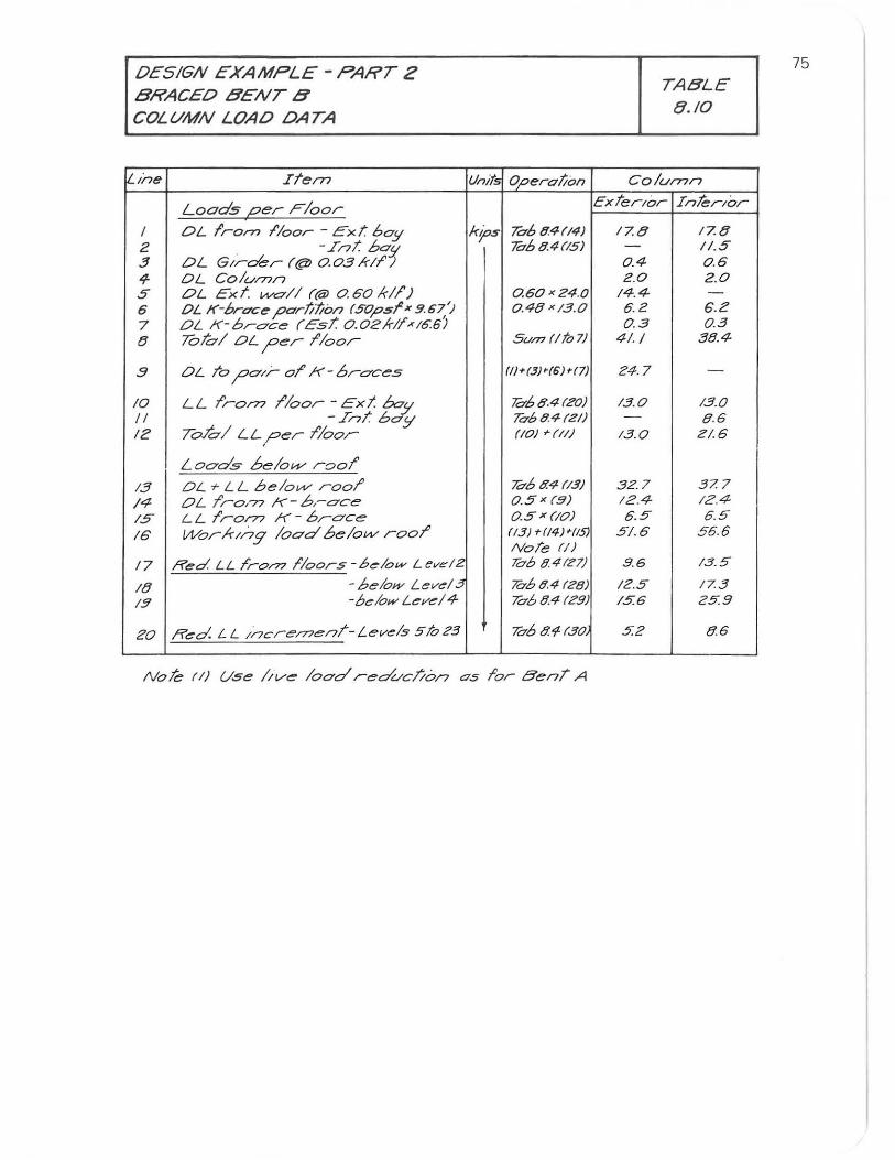
DESIGN EXAMPLE - PART 2 BRACEO BENT B COLUMN LOAO OATA
<..Ine ITem
Loads per Floor
f DL Irom I'loor - Ex!: boy 2 . -In!: boy 3 DL G/rder (@J 0.03 kll'-; 4- OL Colu/77n 5 DL Ext. INa/I ((OJ 0.60/(11') 6 OL K-brace parti'/ion (50psl" 9.67') 7 DL K-oroce (EsT. 0.DZkl/,xl6.6! 8 Tahl DL ;Der I'loor
.9 DL To ;D0';- 01' K-oroces
10 LL I'rom I'loor -Ext boy /I -InT ho;; 12 T%/ LL,per I'loor
L Gods beloW' raol'
13 DL + LL helow rool' 14 DL I'ro,77 K- b,-oce /5 L L I'ro/77 K - Oroce 16 Worlong load belovv rool'
17 Red LL I'ro/77 I'loors -6",,10"- Lev.:IZ
18 -below Levd3 151 -b""lowLeveI4
20 Red. L L IncremenT-Levels 5 h 23
Unit; Operation
kIPs 70694(14) 7O'b94(15)
0.60 x Z4.0 o.4{1 x13.0
SUn? (Ito 7)
(//+(3)-(6) -(7)
'h68.4{ZO) 70'68.4(21) (10) +(11)
'hb tr.4 (/3) 0..5 x (9) D.5 x (/O) (13) +(14)+115) NoTe (I) h6841Z7)
lOb 8.4 (28) 70'684 (Z9)
lOb 8.4(30
Noh (I) Use lIve lood reducl/on as I'or BenT. A
TABLE 8.10
Column
Exter/or InTer/or
17.8 17.8 - 11.5 0.4- 0.6 Z.O 2.0
14.4- -6.Z 6.2 0.3 0..3
41./ 38.4-
24.7 -13.0. 13.0
- {I. 6 13.0. 2/.6
32.7 37. 7 IZ.4 12.4 6.5 6.5
5/.6 56.6
9.6 13.5
IZ.5 17.3 15.6 25.9
5.2 8.6
75
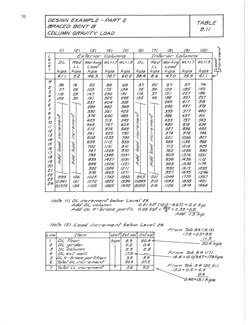
76 OESIGN EXAMPLE - PART 2 BRACEO BENT B
COLUMN GRAVITY LOAO
(I) (Z) (3) (4) (5)
L ExTerior columns e
Red wor-k7 v OL WLxl.7 WL'1.3 e LL LoC'. I kiDS kios lops ir;ps k;ps
41.1 5:2 46.3 787 60.Z
R 2
36 16 52 88 58 77 Z5 10.3 175 134-
3 118 2.9 147 Z50 191 4 5 159 32 1.91 325 248 ---- -r- e37 404 308 6 284 482 368 7 8
330 561 'Ie!!
9 ~ 't 376 640 489
10 4e3 71.9 549
II ~ ~ 46!! 797 609
IZ "- 515 876 669 I: 561 955 13 \) . ~ 730
. ~ 608 10.33 790. 14 ,
15 ) ~ 654 1112 850
16 700 II!!I .910
17 ~ ~ 747 1269 970
18 ~ ~ 7.93 1348 1031
15 939 1427 10!!1
" " 886 1506 1151 20 ZI !!32 1509 1211
2Z 1--,-- -L.... 978 1663 1271
23 t!99 126 1025 1742 1332
24 (1)!!41 131 1072 1822 1334 (e)375 134 110.9 1805 1442
(6)
OL
I(lPs 3(f4
37 75
114, 152
-r-
"-(:
~ b
. \: ,
~ ~
~ 'I:
-;~ (11883 1Z)310
(8) (9)
TABLE 8.11
(10)
Interior Colun>ns ~ Red wor-ir7 'h WL'I.7 WLx/.3 LL LoC'. C \j
'-l~ k;ps kIPs kIps k;ps y 8.6 470 7:1.9 61. I
ZO 57 g7 74 34- Io.!! /85 142 37 151 257 Ig6 46 Ig8 337 257
-- 245 417 318 292 4!!7 379 33!! 577 440
\ 386 657 501
~ 433 737 563 480. 816 6e4
\J 5e7 896 685 ~ 746 574 976 \)
621 1056 807 . ~ 668 11.36 868
~ 715 1216 ge9
-..Q 762 1296 990
~ tJ09 ./376 1051 856 1456 1112
'l: 903 1536 1174 .950. 1615 1235
1-;,;;- !!37 16!!5 1296 10# 1775 1357
210 10.93 1858 1421 216 1126 1.!114 1464
Note (I) OL Increl77enT below Level 23 Add OL colu/77n 0.211dr (/2.0-.9.67) = 0.5 A-~ Add OL K-6roce Forln. 0.0.5 Irsl x 2~.O x 2.33 ;o..t'J
Add 1.3"A-j>
Note (2) Load Incremen/ 6eloIN Level 24
Lln(!' ITem Untf Ext col.
I OL 1I000.r k;ps 8.9 Z OL gIrder O.Z .3 DL cO/l//77/7 e .5 4 OL ex/: wall 17.9 5" OL k-6rocerrTi!ion 3 .9 6 7OI'aloL /"..,cremen/ 33.4-
7 Totol LL Increment 2.6
In/col
20..4 0.4 2.5
.!1.tJ Z7.2
6.0
From ?db 84 (/415) , 17.8 x0.5-89
11.5 eo.4k
From lOb 8.4 (f7) 14.4 x IZ. 0/.9.67= 17.!J kps
I) Fro/77 706 . 8.4' (ZO Z , 13.0 x O.5-6.5 ~ 8.6
0.40"/5:1 kips
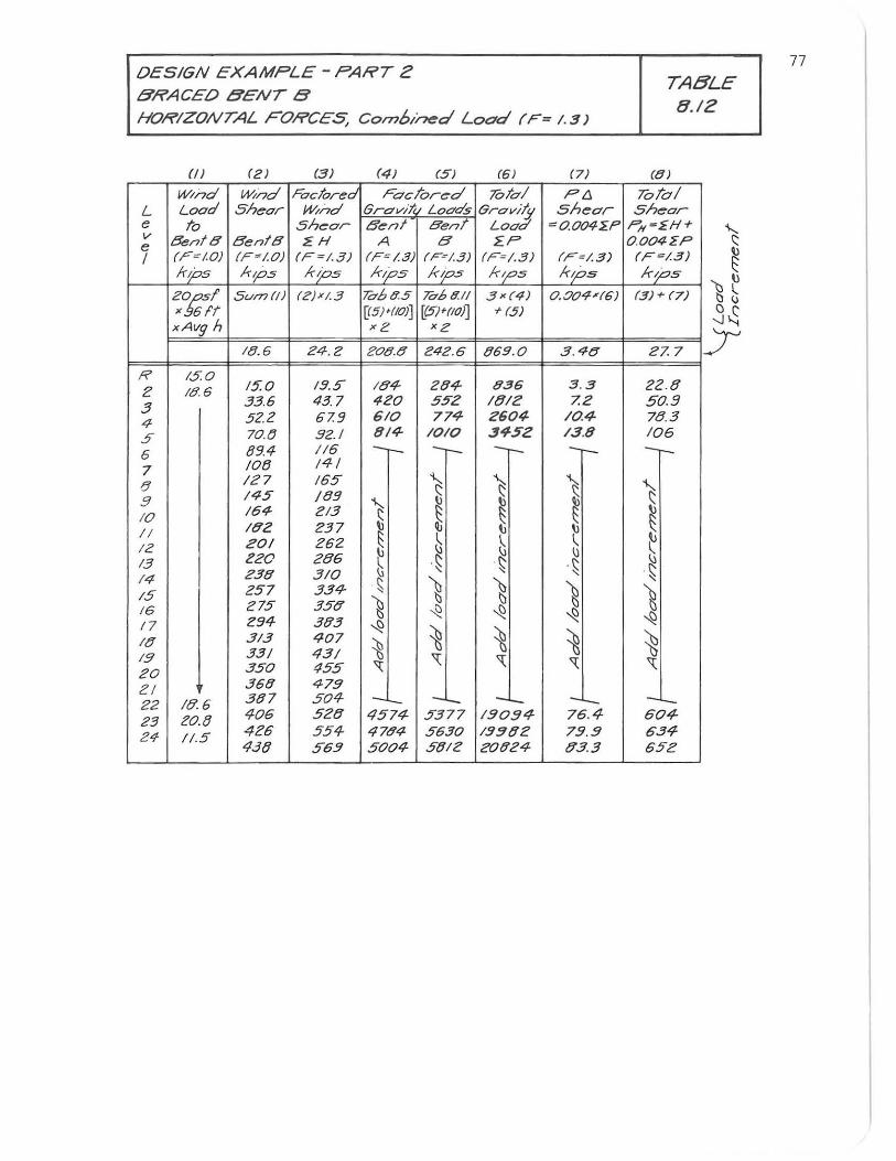
OESIGN EXAMPLE - PART 2
BRACED BENT B HORIZONTAL FORCES, Combined Load (F= 1. 3)
(2 ) (3) (4) (5) (6) (7)
W/nd W;-nd Factored Facl"or~d 7Ota/ ptj
L Load Sh~or w;-nd Grav/!i. Loads Grav;ty Shear e 7'"0 shear Benl Bent Lood =o.o.04~P v BentB BentB ~H A B ~P e 1 (F:(.O) (F~/'o.) (F =I.3) (F: /.3) (F:/.3) (F=I.3) (F-/.3)
kj:>s lops Kj:>S Kj:>S hps k~s kps
20:,51 SU/T7(!) (;?)xI.3 70685 706811 3x(4) 0..0.0.4'(6) x 6ft [(SJ'{IO)j [(5"NIO)] + (5)
xAvg h x2 x2
(8.6 24.2 20.8.8 Z42.6 869.0. 3. ,'ftc!
R 150 ;:: (8.6 15.0 19.!> I B4- 284- 836 3.3
.3 33.6 437 420 552 181t? 7.2
4 52.2 67.9 610 774- 260.4- /0.4-
5. 70..t} 9Z./ 8/4- 10.10 3452 /3.8
6 89.4 116 -r- -r- -r- --7 108 141
FJ 127 /65 S ~ ~ 9 145 189 "\.,.
~ ~ 10 164- 213 S ~ II 182 237 12 20./ 262 S ~ ~ \
~ 13 220. 286
~ . ~ . ~ ~ 238 310. ~ ~ 14 . ~ g g 15 257 334- g 16 275 356' ~ ~ ~ ~ 17 294 383 ~ It! 313 407
~ ~ ~ ~ 19 331 431 '\ '\ 20. 350. 455 " " 21 368 479 22 I ff 6 387 504 - - - -25 ZO.IJ 406 528 4574- 5377 190.94 76.4
24- 11.5 426 554 4784 5630 19!182 79.9 4.38 563 50.04- 5812 20824 lT3.3
TABLE 8.12
(8 )
701"0/ shear P/(~EH+
0 .o.o.4zP (F=/.3) k/'ps
(3)+ (7)
27. 7
22.8 50.9 78.3 106 --"-S ~ t
. ~ ~
g ~
~ '\
-60.4-634-652
77
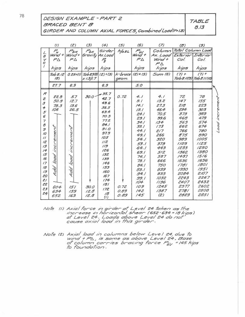
78 DESIGN EXAMPLE - PART 2 BRACED BENT B GIRDER AND COLUMN AXIAL FORCES; Col??btnedLocrd(Fz/.3)
TABLE tJ.l3
(/) (2) (3) (4) (5) (5) (7) (8) (8)
L P,., PbH P6H eird~r ~5L Pov Colvmn lOtal Column Load
e /M&+ /Mhd+ Gn:wi;Y ~.Lood /Mnd+ Ax. Load cxl"~r/or Inkr/or v PI::,. PI::,. r; PI:,. /Mhd+ Co! Col e PI::,. I kips kips kips kips kps kips kips kips
lbb8./2 o.2sx(l) Mbll.!J(O) (2)+(3) k-f,n7,z (Z)x (5) 5vrn (6) (7) f- (7) f-
(tf) x 1.3;1: 7 19~orn. 7d6tf./1~) Tt76 /l 11(10.
27. 7 6.9 6.8 .5.0.
I? 30..0.~
,35.7 ZZ.tJ .5.7 0.. 72 4.1 4. I 72
2 50..8 12.7
42.7 5.1 /5.2 147
3 4:1.6 78.3 /.9.6 56.5
14:1 Z7.3 ZI8 ., 10.6 26.5 /.9. I 46.4 Z'94
5 -- -r-- 63.4 24.1 70.5 37.5
6 70. . .3 Z!J.I 99.6 458
7 77.Z 34:1 /.34- 563
/3 "I-. ~ 84.1 39./ 173 66Z
8
~ 81.0 44,/ 217 766
10. IJ 87.9 48./ 265 875 II ~ 10.5 54./ 3Z'0. .989 lj
~ IZ " Ill' 59./ 37.9 1/0.9 13 " " 118
·64./ 4<13 /Z33 .~ .~ 14 "
IZG 5g.1 5/2 1362 15
~ ~ 132
74.1 587 /4-87 16 /.319
79.1 666 1536 17 ~ -.S? 146
fJ4.1 750. 176'/ 18 ~ ~
IS.!! 6'9.1 6'39 /930.
18
" 160.
.941 933 Z0.84-eo. " 167 99.1 1032 2Z'43
21 - - 174 /04- /136 Z'407
2Z ItJI 60.4- /5/ 30.0. 0..72 /0.9 1245 2577
2.3 634- /59 12.0
172 0. 09 /4-2 /387 278/ 24
652 163 Iz.8 /8 0.0.9 /45 (2) 2029 (I)
Note (I) Ax/ol Torce /n g'rder aT Level 24- Taker7 as /he /ncrease /n hor/zonTal sh~O'r (652 -634- = 16' kps) 0/ Level Z'4. LQO'ds above Level 24 do noT cause ox/ol load /n /hls g,/-der.
78 155 223 .303 389 479 574-674 780. tJ90.
/005 1/25 1250. 13fJO 15/6 /656 /80/ /.951 2/07 2267 2432 250.2 200.8 Z'851
NoTe (2) Ax/o/ load /n co.lu/77ns belo...v Leve I 24, due To wind.,. PI::,. /5 $O'r77e as obove Level 24. Bose aT' co/ur77r,' carr/es broc/ng Torce I'6v : /45 kps /0. /'0.0',,0'0'//0./7.
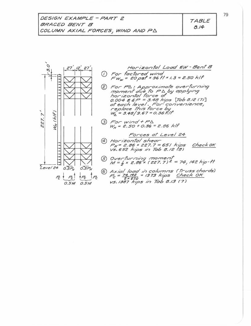
DESIGN EXAMPLE - PART Z
BRACED BENT B TABLE
(J.l4-COLVMN AXIAL FORCeS, WINO AND P~
""-./ "'-../ ""-./ ""-./
, ..... "- ~ ~ * l\J
'-
l\J ~
1""-/ i'V ""-/ Y ,
'Lev~/ 24 O.5P".
Pc ~ Pct '--v-' O.5M
"7 ""-/ ""-./ "'-/
,,/ V ,,/ "'-/ OSPH
~Pc t Pc
-------O.5"M
Horlzon/al Load lEW - Ben/8
(j) For laclored ",,/nd Fww = zopsl' x 96 It x 1.3 = 2.50 kiT
® For p", : Approx'/na/e over-/urn/ng rnprnen/ due /0 P'" by app1l'nj' horizon/all'orce oT 0 . 004 If 0 P = 3.4e KpS [Tab 8.12 (7)] a/ each level. For conven/ence, replace Th/s Torco: by VIi = 3.48/9.67 = 0. 36/flt'
Q) F:::>r vv/nd + p", WH = Z . 50 + 0.36 = Z . 86 KIf'
Forces a/ Level 24
Hor/zon/al shear P H = Z . 86 " ZZ7. 7 = 65/ kps Vs.652 kios /n Ta6 e./z te)
check OK
® Over/",r/7,n9 rno/77en/ M = i x Z.86 x (227. 7) 2 = 74/ /42 kIP-If
® Ax /01 load //7 columns r /russ chords) Pc = 74. /42 = 1373 K/05 ChecK OK
2.1CZ7.0 1-V5. 1387 kps /n 7&b 8.13 (7)
79
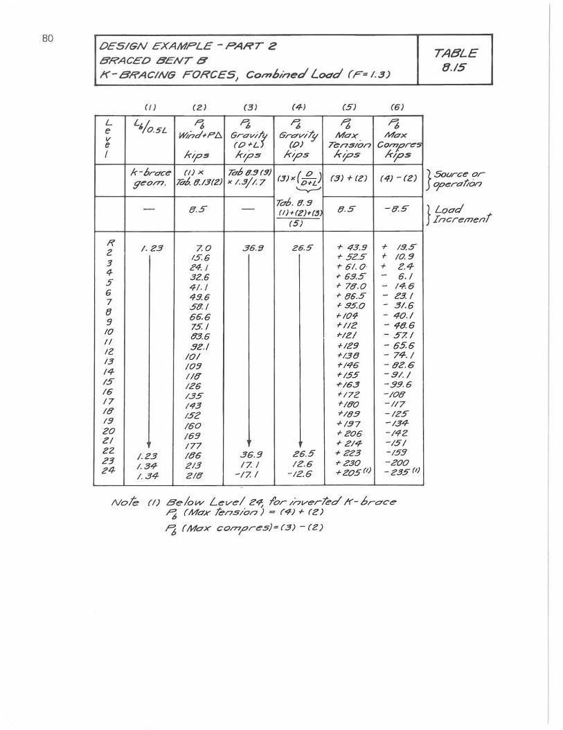
80 DESIGN EXAMPLE - PART 2 BRACED BENT B K-BRACING FORCES, Comb, ned Load (F=/;3)
(II (ZI (31 (41 (5) (51
L L'/O.!iL ~ ~ ~ f6 1'6 e W/ndd'l:!. Grav;t GraviJjt Max Max v
e (O~L (0) Ten5/on C0n7J7r~s I kips kip"" kips kj:>s /"',05
k-tJrac~ (I) x hb9.!'I(9) (3)"(o~) (3)+(ZI (4) -(Z)
9~O/77. hb. 8.13(Z) ,,/.3//. 7 '-v-"
8.5 hb. {J.9
-8.S - - (II + (Z)+(J 8.S
(5)
I? /.23 7.0. 36.5 Z6.5 + 43.9 + /9.5
Z 1.5.5 .,. 525 + /0. 9 :;
N . I .,. 6/.0' + 2.4 4- 32.6 I- 69.5 - 6. / 5 4/. / I- 78.0 - /4. 6 6 49.5 I- 86.5 - 23. / 7
58.1 + 95.0. - 3/.6 {}
66.6 1-/04- - 40../ 9 751 I-//Z - 48.6
10 83.6 'NZ/ - 57. / 1/
Bl!./ +/29 - 656 12
/0./ T/38 - 74./ 13
109 "'146 - 82.6 14- //8 to/55 - .9/.1 /5 126 +/63 -.99.6 /6 /35 +/72 -/08 17 /43 1-/80. -//7 /8 /52 r/89 -/25 19
/60. ..f1.97 -/34 20. /69 r206 -/42 21
177 I- 2/4- -/51 Z2
/.23 /86 36.9 26.5 +223 -/59 23
/.34- 2/3 17. I /2.6 +230 -20.0. 24-
/.34 2/8 -/7. I - /2.6 1-20.5(1) - 235 ('i
Nole (I) Below L~v~/ Z~ f'or /nver/ed /f'- brace J6 (Max Tens/o/?) = (4) I- (2)
J6 (MaX CO/7?pr~s)=(3) - (Z)
TABLE 8./5
} Source or cp~rCflio/?
} Load .Incremenf
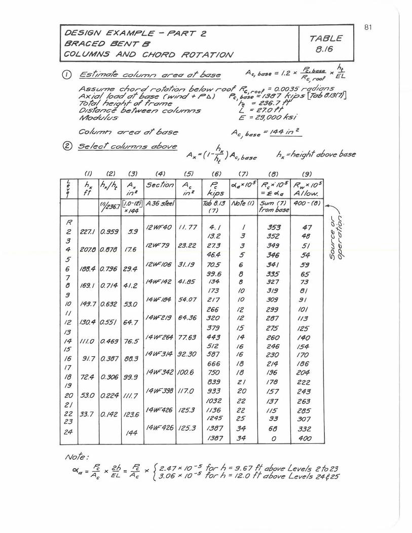
DESIGN EXAMPLE - PART 2
BRACED BENT B TA BLE
8.16 COLUMNS AND CHORD ROTATION
A L - 12 x Pc,bgse x ~ CJ ~a!ltt - . R EL
c .... rool
Ass"'/77e chord ro/al/or> b~/ovv rool' oR,; rool ~ 0.0035 rad/ernS Ax/a/ Iood oT bOS~ (w//,a' + r't» Pc 6,.:S .. =/8<77 /r.ps [7o-b.:1:B(~J 70/0/ h~yhr 01' I'ro/77~ 'It ~ £86.7 ff O/s/o/?c~ be/we~/? cO/U/77/?S L = £7.01'1' Mod""/""5 C = Z!l, 000 Ksi
(2) (3) (4) (5) (6) (8) (9) L
hx hx/ht Ax Sec lion Ac ~ c<"xIOS R "lOs R w XI0 5 ~ c v
ff in Z kips AI/ow. ~ i17 1 =£ 0<,. I
'fi36.7 [{.o -It'D A36~t~1 7i1b 8.13 /\btl!' (I) Swn (7) 400 - ((1)
xl44 (7) fromMSl!'
R 4 . I I 353 47
2 227.1 0.959 ~9 12WF40 11.77
13.2 3 352 48 3
12W79 23.22 27.3 3 349 51 4 207.8 0,878 17.6
5 46.4 5 346 54
6 ItJlJ.4 0.796 29.4 12HFI06 3/./9 70.5 6 341 59
99.6 8 335 65 7 1411F142 41,85 134 tJ 327 73 tJ 169. I 0.714 41,2
173 10 319 81 9
14UFI84 54.07 ZI7 10 309 91 10 14!1.7 0.632 53.0 II 266 12 299 101
130.4 0.551 64, 7 14UF"219 64,36 320 12 287 113
12
13 379 15 275 125
14- II/, 0 0.469 76.5 1411F264 77.63 443 14 260 140
IS 512 16 246 154
9!.7 tJtJ3 I4VV314 92.30 5t}7 16 230 170
16 0.3tJ7 18 ZI<; 186 17 666
14UF"34Z 100.6 750 18 196 Z04 It} 72.4 0.306 99,9
839 17tJ 222 19 21
530 0.224 14VV3J8 117.0 933 20 157 243
20 II/, 7 2/
1032 22 137 263
22 33,7 0./42 123.6 /4VV426 1253 1136 22 115 2tJ5
23 1295 25 93 307
24- 144 14UF426 /25.3 13tJ7 34 68 332
1387 34 0 400
Note:
O(a~ Pc x Zh=APc '" [2.47 x /0. - 5 forh=.9. 671I oboveLeve/s zto23 Ac EL c 3 .06" 10 -5 lor h = 12.0 It above Levels Z4{Z5
81
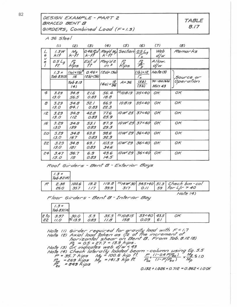
82 DESIGN EXAMPLE - PART 2 BRACEO BENT B G/ROERS, CO/1?6/ned Load (F=I. ~)
A 36 steel
L e v e I
4
8
12
16
20
22
24
0) (2)
1.3W M. kll 1<-lt o.SLs ?-It Ir~s 1.3x IIQ)x(lbJ
holJ.!J(~ 16
h08.13 (4)
.!I.2!! 34.8 /3. 0 56.5
3 .2.9 34.8 /3.0 84.1
3.23 34.8 /3.0 112
.3.29 34.8 13.0 139
3.29 34.8 13.0 /67
3.2:3 34.8 /3.0 /8/
3.47 36.7 /3.0 /{}
1.3 " 7iT6lf.2(1l')
ff 2 .38 /00.6 Z6.0 35.7
1. 3 " 10011.1(14-
(3) (4) (S)
0. 461d If'e1;;~ Sec/ii:)n k-f. *-If Est.d ffe'1'dZ P
Tt //7 .3 kt"s 0.46" (2a)- (.3.7.
(l?b)'(3/» 12
(40-)" -'" A"36
21.6 56. 4- (1)1081.9 0 .Q3 18.8
32.1 66.9 /081.9 0 .83 22.3
42.8 77.6 10W-Z5 o.tl3 25:9
53./ 87..9 10W"Z5 0.83 2.9.3
6.3.8 98.6 /OVVC'9 0.83 32.3
69.1 /C.3.9 /OVV29 0.8.3 3-1.6
6.3 43.6 /0W"C'9 0 .83 14.5
(6) (7)
OSLy r;, ~: a',w
* A//ow. dw
(/b)x/2 Note(.!!) r; (~6) 70 - 100/6'"
(56) Min 43
35.::40 Ok
35'::40 Ok
37<40 01(
37""40 01(
36<40 OK
36<40 01(
36<40 01(
Izto IZ2
3.97 ".30.0 I 11.0 1"1/3.:3
5:3 I 35.3 1 {11/0815 1 33c 40143.51 0.83 /I.{} /58 0.09 1 6/ 1
TABLE 8.17
(8)
Rel?7or)cs
}So~C< ~ 0o",ro/;on
Ok
Ok
OK
Ok
OK
Ok
01<
01<
I
0.132 r/.OZ6 x O. 712 -0.862< 1.00f(
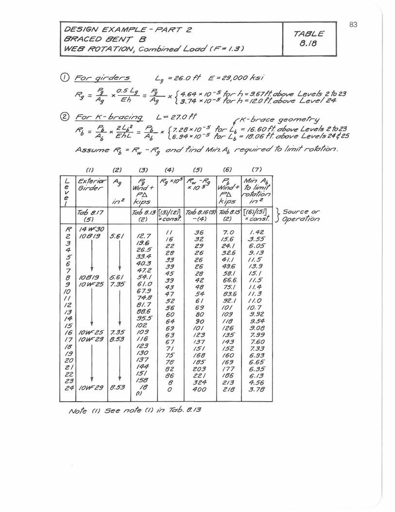
OeSIGN eXAMPLe - PART Z BRACeO BENT B WEB ROTATION) corn6/nea' Load (F-I.3)
Lg = 26.0 It E = 2.9, 000 KS /
TA8LE tJ.ltJ
83
CD For q;rd~r.s
R. - i xo.SLt :9 - As> Eh
= £ x {4.64 >< 10-5 forh =9.67/1.<760 ...... Levels 2 fo23 Ag 3 . 74 >< 10-.5 lor h = IZO Ilobove Level 24
® For K- braCing L = 27.0 It (,K-brace geomeTry
"'6 = "6 x ZLbZ = ~x [7.28><10-5 forL6 = 16. 60f'1.O'boveLevels etoc3
L e v e I
R Z 3 4 5 6 7 8 9. /0 /1 12 1.3 14 15 16 17 /8 19 20 ZI 22 Z3 24
A6 EhL A6 6.94"10 -5 lor L" = 18.0611 O'bove Leve1524(25
ASsume I'i6 = R,., - rtg and i/;-,a' Min. AI, r~9'u'/red 70 t'lmil" rohlion.
(!) (2) (3) (4)
Exter/(;y- Ag r:9 Ry "Ier (hrder l41nd+
pc,. I/-;2 kt,Ps
hb 8.17 hb 0./3 [r3V(Z)~ (51 (21 Xcon5. .
14 W".30 II 10819. 5.6/ 12. 7 16
I I 19.6 22 26.5
20 3.3.4 33 40.3 35 47.2 45
/0819. 5.61 54-.1 35
10W'"25 7 . .35 61.0 43
j j 67.9. 47 74-.8 52 8t. 7
56 88.6 60. 95.5
64 102 65
10W'"25 7.35 109. 6.3
/0W'"Z9 8.53 116 67
j j /23 71 130 75 137 78 /44- 82 /5/ 86 /58 8
10W'"29. 8.53 18 0 {I}
(5) (6)
l'i"'w -Ry xlOs
"6 W/nd+ pc,. ki;:'s
h68.16(9) 7it6tll.5 -(4) (2)
.36 7. 0 32 15.6 29. 24.1 26 32.6 26 41.1 l?6 45.6 28 58.1 42 66.6. 48 75.1 54 83.6 61 92.1 65 101 80 105 50 118
101 126 12.3 135 137 14.3 151 152 /68 /60 185 165 Z03 177 221 186 .324- 213 400 Zl8
(7)
MnA6 to vm/I
!n>/bl/on In 2
[(61(.5)J xconst
IA.? ..3.55 6 .05 9 . 13 11.5 13.5 15.1 11.5 11.4 11 . .3 I/, 0 10. 7 9..52 9.54-9 .0.8 7.59. 7.60 7.33 6.9.3 6 .65 6 . .35 6.13 4.56 3.78
} Source or o,peralion
Note (I) See nole (f) Ii? 7d6. 8.13
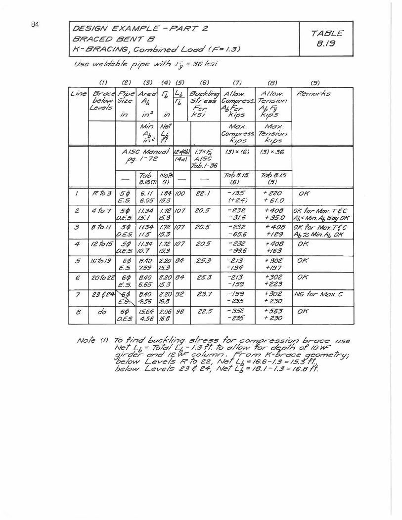
84 OESIGN EXAMPLE -PART Z BRACED BENT B
K-BRACING, Combined Load (F=I.3)
Use w~/dC7ble ?tpe with ;y = 36 Irs!
(IJ (2) (3) (4) (5) (6) (7)
LIne Orueo Pp~ Area f6 ~ 8vekl/i7;J Allow. klow SIze A6 r;, Srres5 C07ress.
Levels Fer 1A6. er In in 2
In ks/ kips
MIn Net Mox.
A" /n z ~~ Compress. !.'ps
A 15C MUI?t/ul ~ 1.7X;; (3) x (6) /"!l 1- 7Z (4,,) AISC
ihb.l-36
Tub Noli! 7dbt!.l5 - (J.I(J(7) (f) - - (6)
I RIo3 5; 6.11 1.(14 100 ZZ./ -135 E.S 6.05 15.3 (+ 24)
2 4107 5; 11.34 1.72 107 20.5 -232 t?E':S 1.5: / /53 -31.6
3 8101/ S¢ //.34 1.72 107 ZOo 5 -23Z D.E.5. /1.5 /53 -656
4 /Z to/5 S¢ 1/.34 1.72 107 20.5 232 t?E.S 10.7 /.5.3 - 39.6
5 16'10/9 6¢ 8.40 Z20 {N Z53 -213 es. 799 /5.3 -134
6 201022 6¢ {J.40 220 tJ4 25.3 -213 E.S. 6.65 153 -/59
7 Z3{Z4 ~ 8.40 Z20 92 23.7 /99 4:56 16t1 -235
8 do 6f; /5.64- 2.06 9t1 Z2.5 -352 Oe5 4.56 /6'<! -235
({})
Allow. "Tension 1,,';; .!/
-;os Max.
?ens/on kl,.bs
(3) x36
To6 {j'./5 (5)
+Z20. + 61.0.
+400 + 350
+408 +IZ9
-405 +163
'302 +/37
+302 +ZZ3
+30Z + 230
+563 +Z30
TABLE 8./9
(51)
Ren?l7rks
o.K
01( 10rMuK. T{C A6 < Mh A6 50';' 01(
OK lor MoK. T(C A" Z Mh. A6 OK
OK
OK
OK
NG lor Max C
o.K
Note (I) To lind bl/c/.-/;nq stress Tor co~re5slon brace (/se Net L6 = Tolbl L6 -/.311 To 0'//0"" f'or ~pl'h 01' 10 Wg,irder and IZ W- c00/77/7. Fro/77 If-brace geo n7e/;-!lJ l>elovv Levels R To Z2, Net L6 = 16.6-1.3 = 1551t, belo"" Levels Z3,; 24, Ne/ L6 = 18. 1-1.3 = 16.5 II:
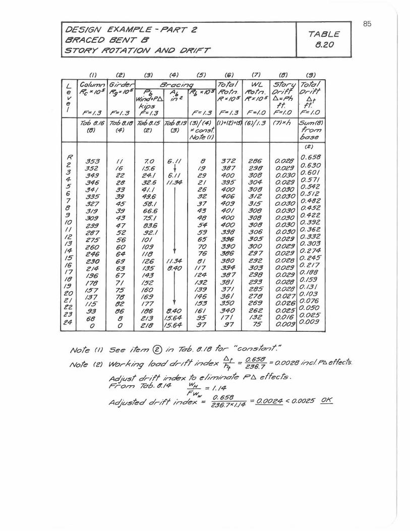
DESIGN EXAMPLE - PART 2 8RACED 8ENT 8 STORY ROTATION ANO ORIFT
(/) (2) (3) (4) (5)
L Col",mn 6/r-der Brac/nq e l'iC"'IO$ I'i$NIO$ ~ A·z "b '/0" v I#nd+f'Ll. In e
~~ I F~/. 3 F~/. 3 ~/.3 F=I.3
To-69.16 To68.18 To-b8.15 To-69.19 (3)/{41 ((1) (4) (2) (3) xcon$t
/lht~(I)
R 353
2 II 7.0. G. II 8
3.52 IG 15.6 t 1.9 3 349 22 24/ 6,/1 29 4- 346 28 32.6 I/.34 21 5 34/ 33 ;;:/./ 26 6 335 39 49.6 32 7 327 45" 58.1 37 8 319 3.9 66.6 43 3 309 43 75./ 48 10 29.9 47 83G 54-II 287 52 32./ S9 12 2'75 5"6 10/ 65 13
e60 60 109 70 !4 246 64 118 76 15" 230 69 126 1/.34 tJI 16 214- 63 /35" 8.40 117 17
136 G7 143
j 124-
18 178 71 /52 132
13 157 75 /60 /39
20 137 78 169 146
ZI I/S 82 177 153
22 .93 86 /86 8.40 161
23 68 8 el3 15.G4- .95"
Z4 0 0 218 15.64- 97
(6) (7) af)
ToTa/ WL 5T07 RoT/? ",,"ol'n . Onr. R'IO'" """><10$ Ll.=ph
If F-I.3 F - /.o. F=I.o.
(I)+llNS, (6)/1.3 (7)xh
372 286 0.0.28 307 298 0..0.29 40.0 30.8 0 .030 395" 30.4- 0.029 400. 30.8 O.O~O 40.6 312 0.030. 40.3 31S 0..0.30 40/ 30.8 0.030 40.0. 30.8 .0.0.30. 400 30.8 0.030 398 30.6 O,O~O
3.96 30.5 0.029 390 30.0 0.0.e9 386 297 0.02.9 380. e.92 0.0.28 394 303 0.0.e9 387 e.98 0..o.e9 38/ 2.93 0.0.Z8 371 285 0.028 36/ Z78 0.0Z7 350 269 0.026 340 262 0 .025 171 /32 0.016 37 75 0.00.9
Note rl) See Ik/?? ® /n ?db. 8 . /8 I'or "con.slanT.q
TABLE tJ.20
(91
ToTal on/I
Itt F=/'O
S",m(8) ;'rom bOoSe
(2)
0 . 658 0..630 0 .60.1 0 .571 0.542 0..512 0..482 0..452 0 .422 0.392 0.. 362 0 .332 0..303 0 .274-0 .245" 0 . e17 0../99 0./59 0..131 0..10.3 0 .0.76 0 .050 0 .0.25" 0 .00.9
Note rZI Wo.r-Iung 1000' dril'l Index ~/ = ~::.~ = 0.00e8 /nc! pc, effect5.
Adjust dnl'f i'7~X To e"'rn/nale ?Ll. ~ffec!S. From ?db. 8./4 w", = I. /4-
. . ' rw", 0..65"8 Ac:lvsled dril'l Index = 236.7"/./4 = 0.0024 <: 0.0.0.e5 OK
85
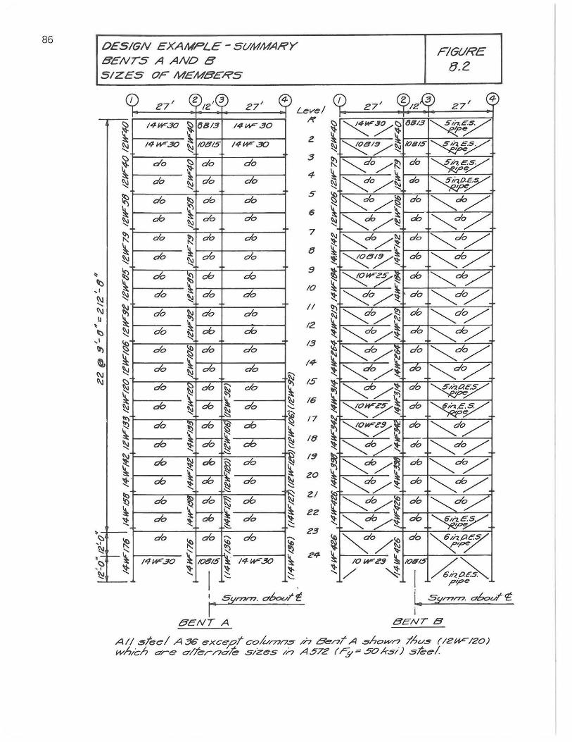
86 OESIGN EXAMPLE - SUMMARY BENTS A AND B SIZES OF MEMBERS
1 Z ,.3 4 27' IZ
~ (J/J13
27' Level /f
14a--.30 14 __ 30
14_30 ~ 10815 14-30
2
do ~ do do
do ~ do do "
3
4
do ~ do do
ab ~ do do ~
5
6
do ~ do do 7
do ~ ~
of, do
of, ~ ab do
do ~ do do '<
10
do ~ do do
do ~ ab ab '<
II
12
do ~ do do
of, ~ do do !:,! N do ~ ab N do ~
~ ~ ab ab do ~ !:,! ~ ~ do ~ ab ~ ab ~ \ "" ab !!:: ab ~ Db ~
~ ".
ab ~ ab ~ do ~ ~ ab ab '\ do ~ !!:: ~ ~
13
/4
/5
16
/7
/(1
1!1
of,
~ do ~ ab ~
ab ab ~ do ~ ~ ~ " do
~ do '" do ......
~ til ~ " ~ 14W"30 iOt!1lS I~ 14W"30 ~ It !!::
~ '-' I , sIIrnn? a6ov1' ~
I' 5ENT A
1
FIGURE 8.2
($)1 :5 27' 12 27' 4
~/~ ~6/3
~~ joe
~//~ 108/$ ~y ~o/~ do ~~ ~o/~ do ~y
~o/~ do ~ab/ ~a6/~ ab ~o/
do ~o/~ ~do/
.~/~ ab ~~ ~...-;?~ ab ~ab/ ~o/~ do ~dc:/ ~o/~ ab ~~ ~o/~ do ~ab/
~/~ do ~~ ~o/~ ab ~dy
~/~ 06 ~y
~~~ do ~v. ~7~ do ~~ ~do/~ do ~do/
~ab/~ ab ~dy
~/~ ab ~'l ~o/~ ab ~dy
~ab/~ ab ~y
~o/~do~~ IOW"G'9 ~ 108105 ~~
/ ~ O/i7PE.S , e I"'P
i.. Slim/?? a60vl' E i
5ENTB
All ~tee/ A 36 exce;:s.t cok,,/77n~ In BenT A ~hOJ,Vn ;!hv.5 (/2/-IFIZO) wh,ch <7re o/Ter17<7h Sizes In A57Z (r;,~50*.s1) she!
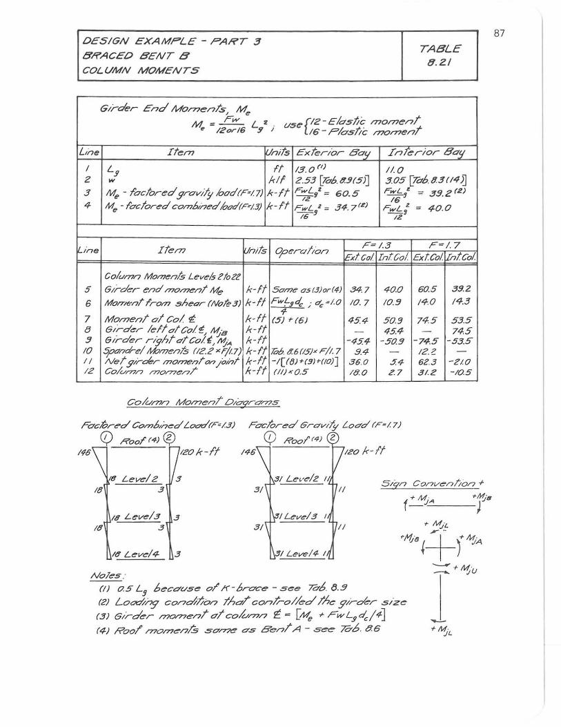
DESIGN EXAMPLE - PART 3
BRACED BENT B
COLUMN MOMENTS
Gir'der End MomenTs, Me
TABLE 8.2/
M '" Fw e 120;16 Ly2 i (/ser:2-El05~c fl7Ofl7eni
16 - ,PIastre /?7Omeni
LIne Item ~.lnits Exterior Bo!! InTerior 8"!L / It 13.0(1) 110 Ly 2 w kif 2.53 [hb.9..9(5)J 305 [7o'6.9.3(14)J 3 M", - foc/ored grov;/y 100d(F'I7) k-ft rwLgz ~ 60.5 rwL; ~ 39.2(Z)
12 16 4- M", - loc/ored comb,aed /ood(F=13) k-It rwL 2 = 34. 7(Z) FwL~2 = 40..0
16 !J
me Itel7?
Column Momen& Levels ztoZ? 5 Girder end moment Me
6 MO/7I .. nt Irol77 shear (NoleS)
7 MomenT 01 Col 1: e Girder lelia/Col'!!, ~B .9 Girder rightatco!(~A 10 S;oo'nd-e/ M;'I77enls (12.2 xF/I.7) II Netglrckr moment on i0ta/ 12 Co/urnn /770776'/7/
FoclOred CO/7?b,ned Loot!rF;/.3)
C) RooT (4) 0
12
Units 0perCl/;on F-I.3
Ext Col Inteo!
k-If SOl77e os(3)orI4) .34.7 40..0 A-If FwLs4 . d. =/.0.
• 'C 10.7 10.!}
A-if 9-
(5) ~ (6) 454 50..9 A-It - 45.4 A-If -45.4 -50..9 A-If lOb. t!.6(15)~ FII. 7 9.4 -A-It -1[ftJJ ~(!WIIO)] 36.0 5.4 A-If (11)"0.5 180. 2.7
Foclored GrovliY Load (F-/. 7)
CD Roo!'''') 2 146 Izok-ff 146 IZO A-If
18 Level2 .3 I{} .3
18 Level3 3 I{} .3
Noles : (I) 05 L
J 6ecO'(/se or f(-broce - see 7C7b. tJ . .9
(Z) Loat://ng condlion tho/ conlrol/ed The girder size
(3) Girder /nomenT aT coh",n ~ = [Me ". FwL.9d,,/4]
(4) Roor 1770177en/.5 some as BenT A - s~ 7C7b. 86
F=/.7 ExtCo! IIntco!
60..5 39.2
140. 14.3
74.5 535 - 74.5
-74.5 -53.5 I2.Z -62.3 -210. .31.2 -10.5
---- + M ' --. "jU
87
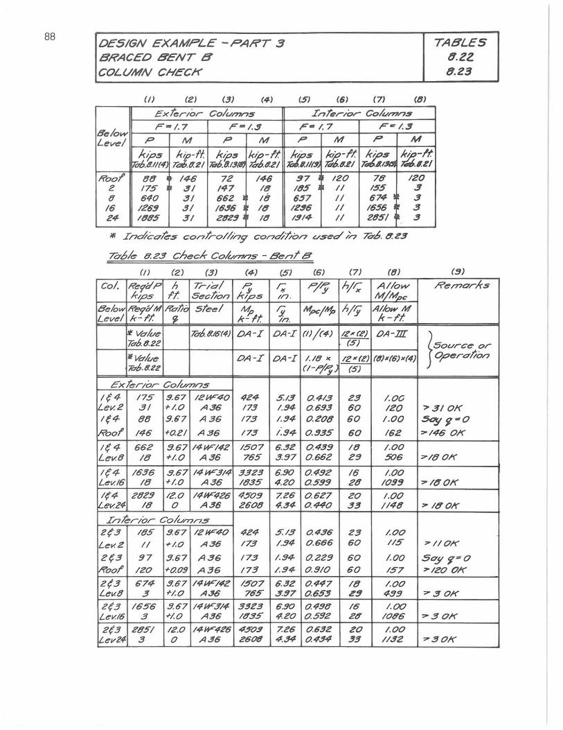
88 DESIGN EXAMPLE -PART .3 BRACED 8ENT 8 COLUMN CHECK
(/) (e) (3) (4-)
ExterIor Colu/71/?$
F#I. 7 F - I . .!I
(S) (6) (7)
Int~rlor Co/v/77ns
F-1.7 Fe I..!I
((1)
TABLES tf.ZZ tf.23
8elow Level p M P M P M P M
ktj>5 7db.41/(4
~-f'1. r. 11.2/
k~$ 7id>.tl.13fIJ
~-It 'o'6.4Z/
11.:$ .1.1/(9,
~-It ",,66..21 :.t:.s
7< ~/m. ~-If. ~.I.ZI
Roo!' 88 146 72 146 97 120 78 120 e 175 31 /47 /(1 /85 /1 155 3 0 640 31 662 /8 657 /1 674 3
16 1269 31 16$6 18 1296 II 16S6 3 24 1885 3/ 2829 /8 19/4 II 28S1 3
i/f Ina7cok$ con/;-o/i//79' cona77/on vsed;/7 70'.6. tT.Z3
To6/~ 8.23 Chec,k- CO~I?7/75 - Bent B
(t) (2) (3) (S) (6) (7) (8) (9)
Col. Re1l1P h Trla/ r; r; P/'Y hj~ Allow Rel?7ar,k-5 k/p5 It Section kips 1/7 . M/~c
8elow Rev;'lI/I1 Rollo steel M. Ii Mpc/~ h/§ AilowM Level k-It sr. k!'lt In. k-f'1
il volve ldb. t!.16(4) OA-I OA-I (1)/(4-) IZ" (l') OA-Dr Tctb.t!.22 (5) } Source or If Vobe OA-I OA-I 1./0 " 12 K(Z) (6.}X(6)K(4) OperatiO/7
7O'b.8.22 {/-P/Pyl (5)
Ext~rlor CO/V/77/7$
1(4 175 9.67 12~40 424 5.13 0.413 23 I . OC L.ev. 2 .31 "'1.0 A36 /73 1.94 0.693 60 120 ">31 OK /(4 88 9.67 A36 /73 1.94 0.208 60 1.00 Soy ~-O
Roof' 146 +azl A36 173 1.94- 0.935 60 /62 :>-146 OK
/q4 662 8.67 14W142 1507 6.'!!2 0.439 18 1.00 Lev.8 18 "'1.0 A36 765 3 .97 0 .662 29 506 7/8 OK
1(4 1636 9.67 14~314 3323 6.90 0.492 16 1.00 L"'I.(/6 18 +1.0 A36 1835 4.Z0 0.599 28 1099 7 Itf OK
1{4 2829 12.0 14~426 4509 7.Z6 0.6Z7 ZO /.00 I ev.Z4- 18 0 A36 2608 4 . .!!4 0.440 33 1148 71tfOl(
Inkrlor Co/u/T7n.5
Z(3 185 9.67 12W40 424 5.13 0.436 Z3 1.00
Lev. 2 II +1.0 A36 173 1.94 0 .666 60 /15 7110K
2(3 97 :1.67 A 3,6 /73 1.94 0.229 60 1.00 Soy ~#O
~ool' 120 +0.09 A36 173 / .94- o.SIO 60 /57 7120 OK
2(.3 674 .9.67 14W'/42 /507 6.32 0.447 /8 /.00 L"'I.(8 3 rI.O A.36 765 .!I97 0.6S.!I i!'!1 499 730K
2(3 1656 5.67 14W314 .3323 6 .90 0.490 16 1.00 L"'I.(16 .3 +1.0 A36 18.35 4.20 0.592 Z8 1086 :>-3 OK
2(3 Z851 12.0 14W426 4509 7.Z6 0.632 ZO 1.00 !Lev24- .3 0 A36 2606 4.34 0.434 33 //32 730K
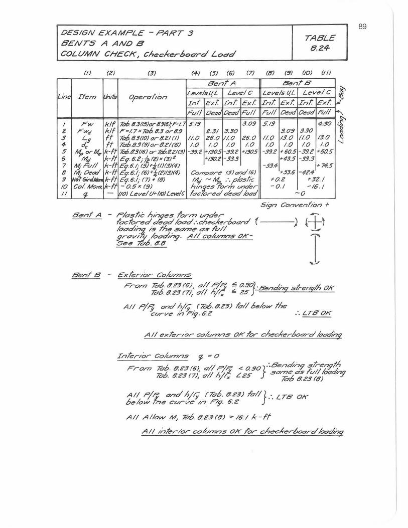
DESIGN EXAMPLE - PART 3 BENTS A ANDB
TABLE 8.24
COL(/MN CHECK, cht!!ckt!!r6oard Load
Lim
I e 3. 4-5 6 7 8 !J 10 II
(e) (3) (4-) (5) (6) (7) (0) (~) (10) (I/)
Bent A &ntB
Item I.hil$ operation LevelslI,L LevelC LevelslI,L LevelC
~ In! EKt Int Ext Int Ext Int Ext
Fd/ Oedd Dedd Full Full Dedd Oedd Full r:-FW kIf he, tl3(15)ortl!J(6~P!.7 5:/~ 3.05 §.15 4.30 i Fwa' kll F-/.7 x h6. tl3 ortl5 2.31 3.30 3.05 3.30
~ L.!J It hb.03(IO) or 021 (I) 11.0 26.0 I/. 0 Z6.0 1/.0 13.0 I/. 0 13.0
<fc It Ta6.9.3(5)orOZla;) 1.0 1.0 /.0 /.0 1.0 1.0 1.0 1.0 -.J
'1> orM .. k-It 706tl3(16) cr 706.tl2t(3) -3!J.2 +/30.5 -3!1.e +/30.5 -3!l.e +60.5 -39.2 +60.5 Ma' k-fl c,!"62; k (Z)X (3)2 +/S0.2 -33.3 +435 -33.3
~·Fu// k-fl 26.1,· (5)+;/:11)(3)(4) -.53.4- +74.5 "1. 0e"'/ k-ft % 6.1; (6) +!;(Z)(3)(4) COl77pO're (5) and (6) +536 -424-Nflt 6irriMon HI '16.1; (7) + (8) M" ~ ~ . '. plastic +o.Z +32.1 Col Mom. k-ft - 0.5 x (9) hinloes Torn? under -0./ -16 . /
r; - 70) Level (/+(ro/Levelc lac ored dead lood -0
Bent A - Plos/;c hInges lorm under --loctored oet7d locrd.·.checlrerboO'rd (----) ~+~
Bente -
10odtnS! is the SOn71!' os I'v/I -'-'" grt7viTl/ loodt~. A/I cO/V/71/7S 011'- r,-.. See -;a,b. ~ t!
ExterIor Colu/77ns
From hb. t? Z3 (6), a/I PI!:; 70'6. t? Z3. (7), 0'11 hit;
All pi;:; ond h/~ (hb. t?Z3.) 1'011 below the cvrve l/7n9.6Z :. LTO'0K
All exterIor colv/77ns OK lor checlrer60ard Ioad-hq
Inkrlor Colv/77/7s 'J - 0
Fro/77 70'6. t?Z3(6), all pip.: '" o.50}:·Bend/,79 sj;--e~th 7i7b 8.Z3 (7), a/I hi/! L Z5 St7ra6 '; j;:~:ood-ny
All pi,,; and hi-$" /70'6. t?Z3) I'all} : . LTO' OK below Tnt!! curve //7 r/g. !!i . .!?
All Allow M; ;o-b. tl.Z3 (e) :>- 16: I Ie - If
All Inhrlor cok.,.rnns OK I'or checlren50ard Ioad-hq
89
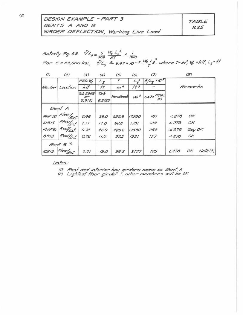
90 DESIGN EXAMPLE - PART 3 BENTS A ANO 0' G/RO£R O£FLEer/ON, Workin9 Live Load
(f) (2) (3) (4) (5) (6) (7)
REO.~ Lg I L3 9
djLg ,,/0S"
Memkr Location kif It in· It 3
7d6t13(~ Ta6 Handbool. (4)3 647" q)ffl. or
tl.!H5) 8.3(10) . (5)
Bent A
/4W-30 Floo,% exT 0.46 26.0 289.6 it7500 /til
/08/5 Floo;f-nl: /. / / //.0. 68.8 /33/ /3g
/4I-V30 Roo/fxl: 0..72 Z6.D 289.6 V7580 282
88/3 Roo1J;,,r 0.72 //.0. 33.5 /33/ /57
Benl8 (I)
/08/9 ~h.rixr. 0.7/ /3.0. 96.2 2/g7 /OS
Notes:
TA8LE 8.2S
(8)
Re/710rkS
.:::27(J OK
.:::278 OK
::::- Z78 SgyDK
L27tJ DK
L278 OK Note(Z)
(IJ Rool ond /nli:rior bOy y/r~r.s sO'me gS 8enT A (2) L,yhksl I'loor .!prder :. other t77ernberS w/l/6e OK
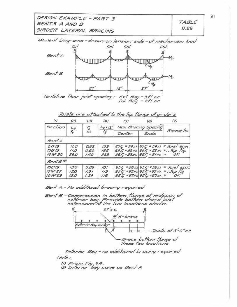
DESIGN EXAMPLE - PART 3 BENTS A AND B
GIRDER LATERAL BRACING
TABLE
8.26
MO/77e/7t OI0.9'r0/77.5 - droU//? on tensIon sIde -at /77eCho/7/5/7"J load Col Col Col col
~'QJIIIllIDJJYf«UlPt~IIIPUJJY+MP I I I Mp I
Bent A
Bents .;t... A. i+ - ~ ~ ......... e;-27
, IZ' Z7'
"Te-nhllve floor .JOIst spod'75" Ext Boy - 31t o.c. In! Bo!! - 2ft oc .
.Tc)ls75 are altached to the top //anqe or (prders I •
(I) (Z) (3) (4) (5) (6) (7)
Sect/on L!j r; Lf. ~/2' Max. Srac/n5' SpaC/;,!:Y Re/7larkS ff In ry Cenrer Ends
BentA tJSI3 11.0 o.tf3 15!J 6'5;; - 5~;/J. 651$ ~ 54/;'. ~ .7(;)/5t MOc. 10815 11.0 0 .00 155 551$ ~5Z/;'. 55;; ~5Z~;' '" ... 10,,0 ~. 14W'30 25.0 /.<10 223 30t;~53;n. 65;; ~91m. '" OK
Bente Ie)
IOBI9 /3.0 0.tJ5 181 65;; -55i~? 65;;~55;/J '" J(NSr %,oc 10W'Z5 /3.0 1.3/ 119 55;; ~05//? 55/f =05>';'. "' .'.10;0 f"9-IOWZ9 13.0 1.34- //6 55;; -07/;'. 55'i ~87/;'. '" OK
Bent A - No adcfillono/ brocln5' re7"(./lred
Bent 8' - Co~res.sIOn In bolrO/71 1'/o/7.9'e 01' /71ldspon 01' exterior bay. ProV/oe,. bolto/71 chord.Jo/sl' exfens/ons at the tl¥<> localions shovvn.
Hi 27'c.c . ff. f' iT
InferIor Boy - /70 odd/Ii0r701 brac,n:? re7"u,red
Nofe:
(I) Fro/71 Pi's? 6.4. (2) Interior boy SOn?e 0.5 Benl' A
91
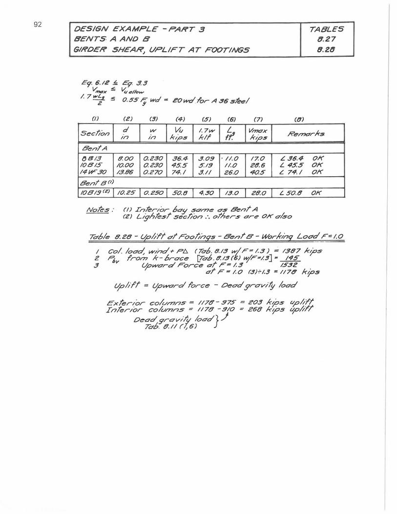
92 DESIGN EXAMPLE -PART 3 IS'ENTSAAND IS'
GIRDER SHEA~ UPLIFT AT FOOTINGS
E'T 6 . /2 ~ E9' 3.3 V Mc7.... ~ ~ 6//0",.,.
/. 7 W;t :5 O. 55 'Y wd ~ eowd 1'or A.!16 $1'_1
(!) (Z) (3) (4) (5) (6) (7) ((7)
TABLES 8 .27
8.2l1
Seclion d w V" / . 7.". f? VI77O'X Ren1Orlr:s In in klp5 kif I<ips
Ben!A
(J813 8.00 0.230 36.4 3.0!! . 11. 0 17.0 L36.4 01( IOBI5 10.00 0.230 4.5.5 .5. I!! 11.0 2(1.6 L 4.5.5 01( 14W-30 /3.86 0.270 74.1 3.1/ Z6.0 40.5 L 74./ 01(
Bent Brl)
IOBI3(Z) 10. ZS I O. Z50 50.8 4.~O 13.0 2lY.0 L 50.tl 01(
Noks: (I) InterIor 60;; $ovne 05 BenT A (Z) Ltgh!f:sT seclion .'. oth",rs are- OK also
ro'6le 8. 28 - upit/! 01' roolinqs - BenT 8' - Worlf-Inq Load F'" 1.0
I col load, WInd + 1"'6 (Tab. 8.13 wi F= 1.3) = /387 I<tjos Z "'6v f'rol7? 1<-6race- LTa6.(1.13r!;) "1'1""#/.3J - /45 3 C10ward Force 01' I""~ /.3 /532
dT I"" - /.0 (3)-i-1.3 '" 117tJ ktjos
C10ltlT = lJoword f'orce - Dead gravi,y load
exTerIor colun7ns = //78-575 = e03 Irtps "Pit/T In/erlor co/ul7?ns = 1/78 -5/0 = e68 I<tjos upit/I
De-ad 9rav/T", load}.J Tab. 8.1/ (1,6)
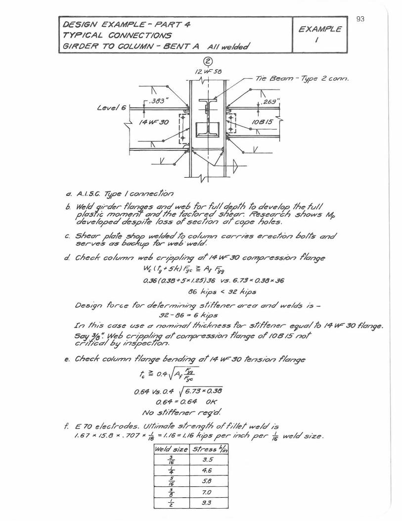
OeSIGN EXAMPLE - PART 4-
TYPICAL CONNECTIONS
(5/I1'OE". TO COLVMN - BENT A A/I wele/eel
EXAMPLE I
7/e Beam - iYf'''" Z conn .
. .383 ., Level 6 1==i======t;:!I1
. 26.9"
14w:" 30
4 . A.1.5C 7!;pe I connecl/on
6. WeJdqlrekr 110"/7(ze5 Qnd web for lufl tkplh 10 dev ... /~ Ihe ruf/ p/05"(; /770/77 ... n7 ond The /gchred sh ... gr: Research shows tf1. tkv ... lop ... d oG-5pik 1055 0/ secl/on cr/ cope holes.
c. shear plole 5Sop ~/e/ed.To colv/77n CCTrr/~5 erec~on 6 0 /4 and serve5 CT5 60'aflfO lor web· _e/oi.
d Checlf- co/(//77/7 web cr~pkny Q/ /4 W-30 cO/77press"o/7 I'lony ...
W. ( ~ r 5ir),y< ~ A, Fyfl
0..36 ((J. 38 + 5" I. 25)36 vs. 6 . 73 " 0.3" " 36
86 ktj:>s < 9Z I<tj:>s
De.stgn loree Tor deler/77I/-7/ny slifkaer O'reO' and .... elo(s IS -
.!1Z - 86 ~ 6/rfos
93
In thIS cO'se vse 0' n0/77I/70'/lh,ch-neS5 f'or s//Ilener e~vO'/ 10 14 W-30 rlonye. SaY. ~ ': Web cripp~iJ5' 0'1 CO/77p~$5/on IICT17ye 01 lOB /5 not cr/l/cQ/6y In.specton.
e. Checlf- colvmn I'/O'nye oendny g/14 uF 30 kns/o/7 /Io-aye
t. ~ o.-rJAf * 0.64 Vs. 0. 4 ..;r6- . 7.-=-:3=-" 0.-=-.--::3:-::'''
0.64=0.64 OK
No stir/ener re9'd.
1. E 70 elec/rodes. Ullimate 5lreogl,4 01' f'1/1e1 H/e/d i5 /.67 " /5.8 x . 707 " ~ = /. /6 = 1.16 I<j>s ?er Inch ?er I~ H/e/d size.
Welclsize stre.u~ 3 3.5 76 I 4.6 + 5 5.8 16 3 ZO ~ I 9.3 Z
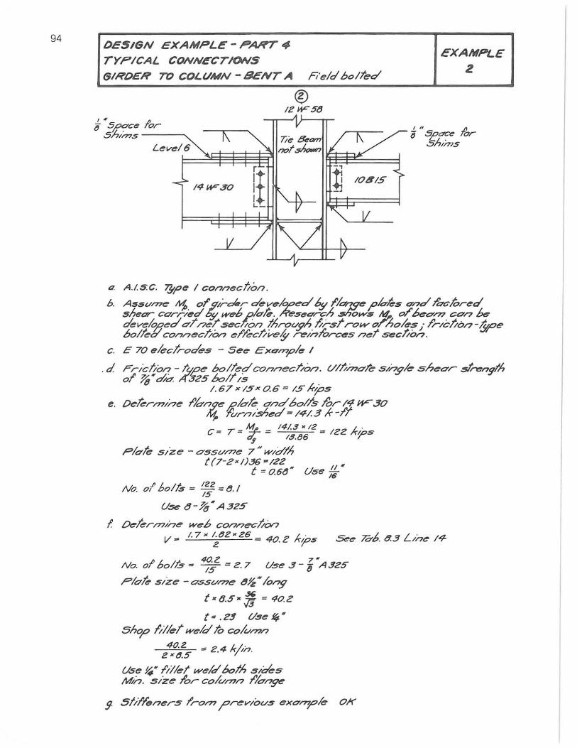
94 DESIGN EXAMP L E - PART .,. TYPICAL CONNECTIONS
GIRDER TO COLVMN - SENT A Fi'eld bolTed
1414"" JO
t7. A .I.5.C. 7Jtpe I connect/on.
EXAMPLE
2
h . A ... sv...,.,.e Jt1; 01' if/roler developed 6y I'bqqe I'lo-ks ."nd Te?clored shear corrJed 5y we-b dok. Research .shows M. 0/ beO'n? con k develolJed dT /7~T seeton throvgh I/rsl ro_ onoks; I'r/c;/on -y,Pe 601lel/ connec;/an el'kc;/ve§- r>!"/nl'orc~s neT secl/on.
c. e 70 eleclrodes - 5e ... Excmple /
. d. rnct/on -l'~e 60 lied co/?necl'/on. (/II//"'dle s/ng/e shedr $'~n9Ih 01' ~ N ~d. ,..:f325 6011/5
1.67 x /5 x 0.6 ~ 15/r',PS
e. O ... kn77/ne I'ldl7(7e gbk cmd 60/15 lOr 14 W-30 ~ 1'vrn/.s4ec/ = 14/.3 /r-I'/ c = T = "1e. = 141.3 -12 = 12Z /rios "1 1.!I.(J6 /
plok s/ze - aSSV/77e 7 # w/dlh t(7-2-1)3G -/22
t = 0.68" Use :; N
M o/' bo/~ = ~ = 8. I o. 15
Use t1- 1&. A 325
f tJeler/77/ne web CO/7/?~;/On v- 1. 7.~tJ2-26 40. 2 i<',Ps
I 4O.Z 7~ No. 0 601/5 - 15 = 2 . 7 Use 3- '8 A32S
Plole sIze -ossv177e t1~·/ong
t· 6.S- Jj = 40.2
t = . 2$ tlse I¥ • 5hqa IIllel w ... 1oI1o cO/V/77/?
40.2 = Z 4 kl,;., 2·8.S . '/"
Use ~. fill ... t w .. IoI60lh SIdeS Mn. size lOr coiun?n I'b~
9- 5111'1'~n ... r5 Iro/77 ,Prev/ovs exonpl... OK
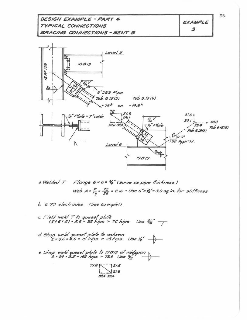
DESIGN EXAMPLE - PAHT .,.
TYPICAL CONNECTIONS
I!IHACING CONNECTIONS - BENT 8
15;:=====::::01 L~~/ S
] 10619 -,
S"DES A-pe 7d1>. ~.IS(5) 7db. 6.IS(6)
EXAMPLE
~
ZI.6 t
95
Z4.1 L_30.o / j3.4 ldb. t!.13(3)
.... /' 706t!.13fZ)
~07Z Lel/'e/6
1.00 1<Prox.
10819
11. w.,./~d T F/O'ng"" 6 >< 6 >< % • ($<7.-.- C7s?~ #'-c/m.,.ss )
w.,.6 A.':; = j~ = Z.l6 - U$t: 6·X~·=.3.0si-/n. Ibr st/l'l'ness
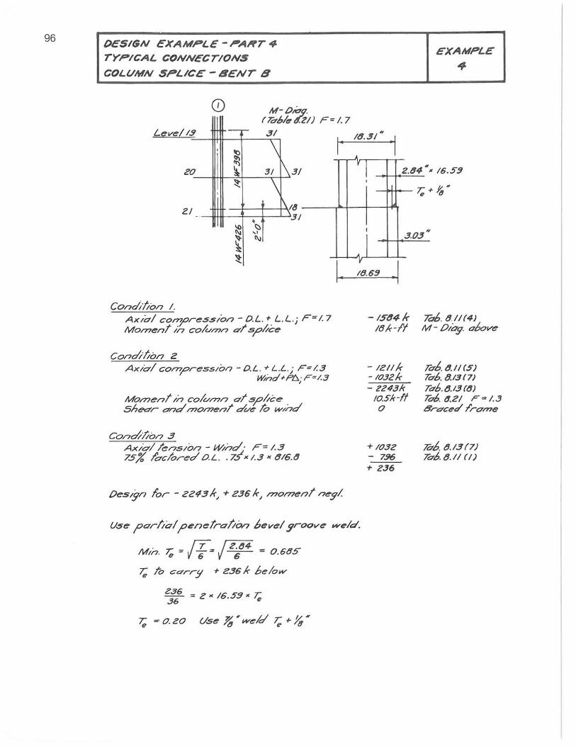
96 DESIGN EXAMPLE-PART4-TYPICAL CONNECTIONS
COLVMN SPLICE - 8ENT 8
CD M-OiOg. ( 7&61tr ,r.ZI) F ~ 1.7
I' 18.'s1" Level 13 '_C"" 31
,
"" \ •
EXAMPLE .,
20 ~ ~ 31 1\ 3/ , I 2.84' K 16.S!J
~ '\ ,
21 , ~ ~
" ~ '" ~
\~ {} 31
,
i y
.1
l T;
3.03"
/tI.6!J
Condil/on I. Ax/al corn;:>re.s.st"on - O.L.' L.L.j F= 1.7 Mon>ent in colu/77n <7"t s;:>,yce
Condil/on 2
Ax/ol con>press/on -O.L . 'L.L.; F=1.3 rl'ind +1"1:>; F~/.3
Mon>ent In column at 5;o,yce Shear ana'rno/77ent a've io WInd
Con~l/ol7 3 AXlol tensIon - WInd· F= 1.3 75% I'aclor<!"o' O.L. . i.! x 1.3 x (116.(1
DeSIgn lor - 2243 k, + 236 k, 1770177e17! neg!.
U.se ;:>arlio/ ;:>enetralto", bevel groove wtrld.
u ~ rT /2.84 ~ mIn. 'e = V 6"= -6- = 0.6tJe>
T; To Cdrr!! + <:36 k below
~6 = 2 • 16.55' T;
~ = O. 20 Use ~ • weld 7,; + Yt, •
- 1$(l4k l(ik-I'I
- 12// k - /032k - f!243k
10.5k-11 o
+1032 - 7.96 .. 236
706. (111(4) M - Olog. above
!db. (1.//(5) 7&6.8.13(7) T06. (1.13 (8)
706. "-21 F = 1.3 8r<7"ctrd Ira,"e
7&,(,. (1.13 (7) Ta6. 8.11 (/)
97
References
1. Leh ig hUn iversity "Plastic Design of Mu ltistory Frames." Lecture Notes Vols. 1, 2. Beth lehem, Pa., Aug 1965.
2. American I ron and Steel Institute "Design of High Rise Steel Framed Buildings." Continuing Education Program, New York, N.Y.
3. American I nstitute of Steel Construction Steel Construction Manual 6th Ed. AISC New York, NY., 1963.
4. U.S.A. Standard Inst itute "Minimum Design Loads in Build ings and Other Structures." Amer ican Standard Bui lding Code A58.1-1955.
5. S.C. Goel and G.V. Berg "I nelastic Earthquake Response of Tall Steel Frames." ASCE Conference, Seattle Wash. 1967. Conference Preprint 503.
6. T.V. Galambos
"Lateral Support for Tier Building Frames," AISC Eng. Journal, Vol. 1, p. 16, Jan. 1964.
7. Le-Wu Lu and H. Kamalvand "Ultimate Strength of Laterally Loaded Columns." Fritz Engineering Laboratory Report 273.52, Lehigh University, November 1966.
8. N. M. Newmark
"Numeri cal Procedures for Computing Deflections, Moments & Buckling Loads." Trans. ASCE Vol. 108, p. 1161, 1943.
9. O. W. Blodgett
"Design of Welded Structures." The James F. Lincoln Arc Welding Foundation, Cleveland, Ohio, 1966.
10. J.G. Bouwkamp
"Concept of Tubular-Joint Design." Proceedi ngs ASCE, Vol. 90, ST2, p. 3864, 1964.
98 Design Aid I
PROPERTI ES OF BEAM-COLUMNS
A rx ry Z A36 A572 Fy = 50 A441 Section Py Mp Py Mp Fy Py Mp
in2 in in in3 kips k-ft k ips k-ft ksi kips k-ft
14111F426 125.3 7.26 4.34 863.3 4509 2608 6265 3622 42 5263 3042
14V1F398 117.0 7.1 7 4.31 803.0 42 11 2409 5850 3346 42 4914 2811
14V1F370 108.8 7.08 4.27 737.3 3916 22 12 5440 3072 42 4570 2580
14V1F 342 100.6 6.99 4.24 637.0 362 1 2019 5030 2804 42 4225 2355
14V1F320 94.12 6.63 4.17 592.2 3388 1777 4706 2468 42 3953 2073
14V1F314 92.30 6.90 4.20 611.5 3323 1835 4625 2547 42 3885 2139
14V1F287 84.37 6.81 4.17 551.6 3037 1655 4218 2298 42 3543 1930
14V1F264 77.63 6.74 4.14 502.4 2795 1507 3882 2093 42 3261 1758
14V1F 246 72.33 6.68 4.12 464.5 2604 1394 36 16 1935 42 3037 1625
14V1F237 69.69 6.65 4.1 1 445.4 2509 1336 3484 1856 42 2926 1559
14V1F228 67.06 6.62 4.10 427.2 2414 1282 3353 1780 42 2816 1495
14V1F219 64.36 6.59 4.08 408.0 2317 1224 3218 1700 42 2703 1428
14V1F211 62.07 6.56 4.07 39 1.7 2235 1175 3104 1632 46 2855 1502
14V1F202 59.39 6.54 4.06 373.6 2138 1121 2970 1556 46 2732 1432
14V1F 193 56.73 6.5 1 4.05 355. 1 2042 1065 2836 1480 46 2609 1362 14V1F 184 54.07 6.49 4.04 337.5 1947 10 13 2704 1406 46 2488 1294 14111F176 51 .73 6.45 4.02 321.3 1862 964 2586 1339 46 2379 1232 14V1F167 49.09 6.42 401 302.9 1767 909 2454 1262 46 2258 1161 14V1F158 46.47 6.40 4.00 286.3 1673 859 2324 1193 46 2138 1098 14V1F150 44.08 6.37 3.99 270.2 1587 811 2204 1125 46 2028 1035 14V1F142 41.85 6.32 3.97 254.8 1507 765 46 14V1F136 39.98 6.31 3.77 242.7 1439 728 1999 1011 50 1999 1011 14V1F127 37.33 6.29 3.76 225.9 1344 678 1867 941 50 1867 941 14V1F 119 34.99 6.26 3.75 210.9 1260 633 50 14V1Fll1 32.65 6.23 3.73 196.0 1175 588 50 14V1F84 24.71 6.13 3.02 145.4 890 436 50 14V1F78 22.94 6.09 3.00 134.0 826 402 50 14V1F74 21.76 6.05 2.48 125.6 783 377 1088 523 50 1088 523
14V1F68 20.00 6.02 2.46 114.8 720 344 1000 478 50 1000 478
14V1F61 17.94 5.98 2.45 102.4 646 307 50
14V1F53 15.59 5.90 1.92 87.1 561 26 1 780' 363 50 780' 363
14V1F48 14. 11 5.86 1.91 78.5 508 236 706' 327 50 706' 327
14V1F43 12.65 5.82 1.89 69.7 455" 209 50
Note: Values of Py and Mp are shown for compact sect ions on ly.
Fy = 36 ksi; ~ <;;; 17.4, ~ <;;; 43 Fy = 50 ksi; ~ <;;; 14.8, ~ <;;; 36
'Section satisfies !:..requirement, but may exceed!!...- limitat ions shown below. t w
d Fy = 36 ksi; -;:;;<;;;70-100P/Py
but need not be less than 43
d Fy = 50 ksi ; -;:;; <;;; 60-85 P/Py
but need not be less than 36
99
Design Aid I-(Cont.)
PROPERTIES OF BEAM-COLUMNS
A Z A36 A572 F = 50 A441 'x 'y
y
Section Py Mp Py Mp F y Py Mp
in2 in in in3 kips k-ft kips k-ft ksi kips k-ft
12W'"190 55.86 5.82 3.25 311.5 2011 935 2793 1298 46 2570 1194 12W'"161 47.38 5.70 3.20 259.7 1706 778 2369 1082 46 2179 996 12W'"133 39.11 5.59 3.16 209.7 1408 629 1956 874 46 1800 804 12W'"120 35.31 5.51 3.13 186.4 1271 559 1766 777 46 1625 715 12W'"106 31.19 5.46 3.11 163.4 1123 490 1560 681 50 1560 681
12W'"99 29.09 5.43 3.09 151.8 1047 455 1454 632 50 1454 632 12W'"92 27.06 5.40 3.08 140.2 974 421 1353 584 50
12W'"85 24.98 5.38 3.07 129.1 899 387 50
12W'"79 23.22 5.34 305 119.3 836 358 50
12W'"58 17.06 5.28 2.51 86.5 614 260 50
12W'"53 15.59 5.23 2.48 78.2 561 235 50
12W'"50 14.71 5.18 1.96 72.6 530 218 736 302 50 736 302 12W'"45 13.24 5.15 1.94 64.9 477 195 662 270 50 662 270 12W'"40 11.77 5.13 1.94 57.6 424 173 50
10W'"112 32.92 4.67 2.67 147.5 1184 443 1646 615 50 1646 615 1 OW'" 1 00 29.43 4.61 2.65 130.1 1058 390 1472 542 50 1472 542 10W'"89 26.19 4.55 2.63 114.4 943 343 1310 477 50 1310 477 10W'"77 22.67 4.49 2.60 97.7 816 293 1134 407 50 1134 407 10W'"72 21.18 4.46 2.59 90.7 762 272 1059 378 50 1059 378
10W'"66 19.41 4.44 2.58 82.8 699 248 970 345 50 970 345 10W'"60 17.66 4.41 2.57 75.1 636 225 883 313 50 883 313 10W'"54 15.88 4.39 2.56 67.0 572 201 50
10W'"45 13.24 4.33 2.00 55.0 477 165 662 229 50 662 229
1OW'"39 11.48 4.27 1.98 47.0 413 141 50
8W'"67 19.70 3.71 2.12 70.1 709 210 985 292 50 985 292 8W'"58 17.06 3.65 2.10 59.9 614 180 853 250 50 853 250 8W'"48 14.11 3.61 2.08 49.0 508 147 706 204 50 706 204 8W'"40 11.76 3.53 2.04 39.9 423 120 588 166 50 588 166 8W'"35 10.30 3.50 2.03 34.7 371 104 50 8W'"28 8.23 3.45 1.62 27. 1 296 81 .3 412 113 50 412 113 8W'"24 7.06 3.42 1.61 23.1 254 69.3 50 8W'"20 5.88 3.43 1.20 19.1 212 57.3 294 79.6 50 294 79.6 8W'"17 5.00 3.36 1.16 15.8 180 47.4 50
100 1.0 VV / ~
20 25 30 35 49
1/ 1/ V '" / V
0 .8 I II / II
I I III IN- ·4 0-IT. I 0.6 -~n
M ,.-Mpc ·20
Fy = 36 ksi
I ~/O.31 q=O
-I--I---
--0.4
0.2 FJ ~~M
~ 1-9 h
--------- -- ---
p - -o
o 0.01 0.02 0.03 0.04 0.05
e (Radians)
D.A.n-1
1.0 2025 30 35 40
/ / / i..-/ ./
I II /
0.8 II I I II /
0.6
I / 40- h
'. 35 Fy = 36 ksi - -
0.4
0.2
30
I ~/O.41 - -25
20 - -
IIITI q=O - -
/IIIV /~M - -
fA - -
9 - -
;. - -h - -
- -
- -p - --
o o 0.01 0 .02 0 .03 0.04 0 .05
e (Radians)
D.A.n-2
M Mpc
M Mpc
1.0 20 253035
1/ V :;.... ~ /i/ V v V-
I '/ V v O.B I I
J. - 1-40'.!!. '. 35 Fy = 36 ksi 0
- I-
25 I ~y = 0.5 I - I-
20 - I-
IIIfY q=O - I-
ffl/J p - I-
~ r; "'M - I-
_9 - l-
f - l-n - I-
0.6
0.4
0 .2 - I-- -
p - '-
o o 0.01 0.02 0.03 0.04 0 .05
e ( Radians)
2025
V- I.--: ~ -t-- 3O'=.tl II j /
.... t--... "" I 'x V '/ ~ "\ I
II \ 35 '/ \ i
If I
)'40 0.6 HI/HI'I m'H+-+-+-!-++-H-+--+-\--+-+-..L-I-LJC~----L..L-4-H
lIIN Fy =36 ksi I ~x" 06 I =~ HfIIIt- q -0 -I-
IJfrI+---H-+++-H-+++-H-l r; ~M =~ - I-
0.4
-I-
0.2 n -I-- I-- I-
P - r-
o o 0.01 0 .02 0.03 0.04 0.05
e (Radians)
101
D.A.n-3
D.A. II-4
102
M Mpc
M Mpc
1.0
0 .8
0.6
0.4
0.2
o
1.0
0.8
0.6
0.4
0.2
o
'I ~ '/ I) r r, IMI rrJ
UN fill
fill/
~
o
if':; II '/ '/
1111/
'"II -I-
o
f""
V /: 1/. V II
0 .01
V r--.. " I\,
V " \
, I: , 4
0.01
2 ..... "-
.....,
"- 1'\ I
\. \ \ 3
1\ / \ I
Fy = 36 ksi l-I-
35 I ~/0.71 l-I-
l-I-q=O l-I-
p l-I-I ,,--;l'M l-I-40
f-9 l-I-
~ l-I-h l-I-
l-I-
l-I-p l-I-
0 .02 0.03 0 .04 0.05
e (Radians)
D.A . II-5
20~*- I I I
" x
/Vr--- -I20;J!. i \ 25 /"
~ I rx
I \ ! I II"' I I 1\ I
0 h\ 25
Fy = 36 ksi I Fy = 36ksi I
I :/~.81 iW I I ~y=0.9 I ! ,
q= q=O
35 /' ~M 30 /r\M
I
J. f--9 1 _9 h
, h
35 P I P I
0.02 o 0.01 0.02
e (Radians)
D.A.II-6
M Mpc
M Mpc
1.0
O.B
0.6
0.4
0.2
o
1.0
O.B
0.6
0.4
0.2
o
I
II I
II I I '/ 'I
I III rll
IIIi lY''! I I,
o
/
I I I
II ! 'I I I I 'I 1/ I
II. 'fL VII],!
-!11ft
o
v -V ....-/ 1/ ./
/ / /
/ / II ! j /
1
0.01
fo-
/ I-'" v V V V
/ / V /
/ 'j
0.01
103
h
I-~O= r.
25 ....- ~ 30
...... ,...... :--:+-35
I" 40
Fy = 36 ksi f- f-
I ~/0.31 f- f-
l-f-q=-I.O l-I-
P f- f-"-;~M f- f-
/ l-I-~ fo-f-9 f- f-
h f- f-
\ f- f-
'-'~M l-I-
p f-I-
0.02 0.03 0.04 0.05
e (Radians)
D.A.II-7
~ f"-... r- f"-... 20= .h. ...... r-..... ,...... ..... r •
r-.. :---~ ....... 5 1
I"'- ....... I'~O
" ....... 3!i ~\b
Fy = 36 ksi - f-
I ~/OA I P - f-- l-
q =-1.0 • /C ~M - f-- f-
I- _9 - I-h - f-
- f-
'-!,!M - I-
p - I-
0.02 0.03 0.04 0.05
e (Radians)
D.A.II-8
104 1.0
0.8 v - r--. h 11,/ ...... r-,. ,20= '.
I / / ...... r-,. r-r-- ,""'" 25
0.6 H---!lI/-I+fI-jIYl--+-+-+-H-+-+-+-".f"'o.p...j.' Fy = 36 ksi il ~3! ~
~~~~~~I I:~~:::~~:::~:::~~:::~:::~~:::!:::~~"'::\ "10" ~ H+H'.,\IJ+It-H-++--HH-++-t-H--1 q =-1. 0
p
- f-
-f-
-f--f--f-0.4
~l'M -f-
-f--f-
--
11111 Nil
'I 0 .2 INII --- ---
o o 0.01 0.02 0.03 0.04 0.05
e (Radians)
D.A.IT-9
1.0
v ...... V ...... r-r--
0.8
1/ V ..... t-... r-r-- "- 20= l!. L 1/ t-... r-.. " __ I '.
/ "-I'. " ~25 Fy = 36 ksi f- f-I l"-I"- " \ I ~y = 0.6 I 'j I'\. I"- " f- f-
30 f- f-I\. I\.. \ I
~35 q=-1.0 f- f-
p - f-'\ \ ~ l'M "
- f-40 - f-
-II1II f-9 I - f-rt! h - f-
0.6
0.4
0.2 - f-
'-!~M - f-
p - f-o
o 0.01 0 .02 0.03 0.04 0 .05
e (Radians)
D.A.II-IO
105 1.0
/ f.- ...... f', O.S
I.- "- "-
II I.- ....., "- '\ r-.. 'I V v ....., "- ,'\ '\ I" 20=~ Fy = 36 ksi - I-IIJ 1/ '\ l'\ 1,\ 1'\ \ I ~y = 0.7 I - f-rI 1,\ 1\ ~ 25 - I-fl \
II \ \ '\ q=-LO - I-
13~ P - f-
j /C~M - f-\ \ ~3~ 1\
- f-
/ _9 - I-
\[ i h - f-N40 - f-
0.6
0.4
0 .2
" ~M - f-
P - I-o
o 0.01 0.02 0.03 0.04 0 .05
e (Radians)
D.A.ll-11
1.0
O.s /' -...
.......
- \'\ f \ V '\\. \. Fy .= 36 ksi r- Fy = 36 ksi
'/ '\ 20'¥i_ I p/osl I ~y =0.9 I '/ \ '/ 1\ If \2~--
P . 20=.!!. q=-LO
\ r. q=-LO , \ I \ \
"'~M r~M I
J \ \ ,30 \ ~,
\ 1 _9 A _9 \ \~-- h - h
30 \ 'I' 35 -II 40
0.6
0.4
0.2
~40 '-l!M I '-l!M \ P I
p o
o 0.01 0.02 o 0.01 0.02
e (Radians)
D.A.ll-12
106
P Py
1.0
0.9
0 .8
0.6
0.4
0.2
o
-
-f-
-
-
--
-
-
o
LATERAL TORSIONAL BUCKLING 'IF COLUMNS, A36 STEEL
MAJOR AXIS BENDING
I I hJ 20--
·2! fy,
35 30
4. 40 r--
50-- -r-55 -l"- I'---"":::1"- ......... -r- ......... r-
'u 70 -
-- --lor
I~ I"-~ ..... ---f-!.2U p
r.~
) q = + 1 Cm=O.4
M~'./ rx Iry = 1.7 p
0.2 0.4
8 b ClO -...;;.,
I"--,...
r---
M Mpc
r-----I'--r-
0.6
-I"- -r---......... "'"' ......... r- -r-......... -....... "'"' r--..... -r- ---r-
0.8
r--
.........
--.........
--..
......
.........
.........
"-' ..J < u VI
0 - "-' 0 - z ~
........ x "-'
.....
--
......
........
-
1.0
D.A.ill-lo
1.0
0.8
0.6
0.4
0.2
o o
IN-PLANE BENDING 'IF COLUMNS, A36 STEEL
MAJOR AXIS
p r.~M
J
M~V P
0.2
q = + I em= 0.4
0.4
M Mpc
0.6 0.8
1\ h 40=rx
1.0
107
D.A.Iil-lb
108
P Py
1.0
0 . . 9
0 .8
0.6
0.4
0.2
o
to------.."
-..
---
----
o
LATERAL TORSIONAL BUCKLING 'IF COLUMNS, A36 STEEL
MAJOR AXIS BENDING
2
3~ --- -r-r--.. -l'"'-I'- _45 -"1-- r--- ~
r-- -~S- -.. r-.... ........ r-..... r-.... r...... r-..... r- -.. -.. , -.. N I-... " ---- ..... -- -r-....... 60 -I'--....... -.. r-.... 70-----r-.... ........ 1--........ ......... ...... --.. r-... -.. ~O
......... 90 .... r-.... -.. -.. ......... r--.:: .... ...........
r-.... I---.. ..... ~O ........ ..... I-- r-. r--J 10 r-....
12(...... ...... p -.. r-. ....... r-...., ...........
~~ I--~ ........ I ........... .........
q=O \ Cm=O.6
rX/ry=I.7 p
0.2 0.4 0.6
M Mpc
I h 0=-
--~ I'---I'--.. ~O -.. I"-
r-.... I"'- ..... ........ I"-1"'-40 " ""'-I"'-
50 I-- ......... -......... ......
r-.... ........ ..........
....... ........ " r-.... " r-.... .......
.......... ...... ""'-i"-- r-..... " ..... r...... ......... " r-.....
........... .........
, .........
........ r-..... i"'-
......... l"'- I"-., I"-
...... i'-. I"-
0.8
w -I - ct u
......... U)
0 w
......... 0 z ~
"-x w
.........
" "-...
"-
"'-.......
,,'
1.0
D.A. ill-2a
P Py
1.0
0.8
0.6
0.4
0.2
o o
IN-PLANE BENDING 'IF COLUMNS, A36 STEEL
MAJOR AXIS
--......... .........
P /1f\M
I
p
0.2
q=O Cm=0.6
0.4
M Mpc
"'-
0 .6 0.8
" '" " \
:--.-,,"\ , \ \
[\ \\I
\1\
1\
h 20=rx
25
30
35
40
1.0
109
D.A.ill-2b
110
P Py
0.6
LATERAL TORSIONAL BUCKLING 'IF COLUMNS, A36 STEEL
MAJOR AXIS BENDING
0. 4 P ......... 1'-... ",........ ,,"\ i\ \ \ \
f-,r,~ " 1'-.." ,,'\ \ \ \ \ I--f- / "I'-.......... '- \. i\ \ \
" ", \.. i\. \ \ \ 0.2 -q =·-1 = \ M Cm= 1.0
", \.. \.. .\ \ ~ \
W ..J c( <.> (f)
o w o z ~ x w
\. I,.J rx/ ry =1.7 . ~- ~~~~~~4-~~+-~~ - P'---
o o 0.2 0.4
M Mpc
0.6 0.8 1.0
D.A.IIL-3a
1.0
0.8
0.6
0.4
0.2
o o
IN -PLANE BENDING w= COLUMNS, A36 STEEL
MAJOR AXIS
......... .......... ...... r-.. '" ......
'" "'- "- "-~ "\. '\ \ r"\. f\
'\. ['... \ \ \ I\. 1\ I\. 1\ \ \ \ \ I~ 1\
\ ,\ '"" _\
\ \
1\ \ P
r!,-M \
/
\ q =-1 M Cm = 1.0
\....; ~ p
\2
\ ~ \ \ \ \
\
1 r\ r-.\
0.2 0.4 0 .6 0.8
M Mpc
111
l~ p= ?;
2!:
3 P . \." 5 \
" \ .~
\ \
\ \\ \
1.0
D.A . ill-3b

NOTES
Related Documents