PLASMA-ASSISTED GASIFICATION OF REJECTED WASTE FROM AN MBT PLANT FOR SYNGAS PRODUCTION Thipsuphin Hinsui 1* , Weerachai Arjharn 2 , and Pansa Liplap 2 Received: May 05, 2014; Revised: July 12, 2014; Accepted: July 18, 2014 Abstract Municipal solid waste (MSW) becomes a very critical issue in many regions of the world. Various technologies, either alone or in combination, have been used to solve this problem. Mechanical and biological treatment (MBT) is one of the most effective methods for MSW management to divide MSW into different fractions, including rejected waste which presently requires landfill disposal. A waste-to- energy process like gasification is an alternative to landfills but requires feedstock with a homogeneous form and low moisture content. This work aims to study whether rejected waste can be used for energy production through the gasification process with assistance from an external heat source from a plasma torch. The syngas characteristics and system performance were tied to the different feedstock moisture content levels ranging from 10 to 40 wt% (wb). The results showed that the plasma torch could reduce the limits of the feedstock properties in traditional gasification. However, an increase in the moisture content resulted in a reduction of the temperature inside the gasifier, causing a variation in the syngas characteristics. The calorific values were found to decrease proportionally from 8.26 to 4.82 MJ N -1 m -3 when there was an increase in the moisture content from 10 to 40 wt% (wb). The performance evaluation of the plasma-assisted gasification system, i.e. the syngas yield, energy yield, and gasification efficiency, were negatively influenced by the moisture content in the rejected waste. Overall, rejected waste can serve as a feedstock for quality syngas production using the plasma-assisted gasification system. Keywords: Rejected waste mechanical and biological treatment, energy production, plasma, gasification, waste-to-energy Introduction Municipal solid waste (MSW), commonly known as trash or garbage, is a major issue in many countries. Its quantity has risen over the years in both industrialized and developing countries, and its disposal has become increasingly problematic (Kwak et al., 2006). Currently, the most widely used management methods are landfill or open dumping; however, the limited areas for the disposal of waste and the increasing concern over health hazards and environmental 1 School of Environmental Engineering, Institute of Engineering, Suranaree University of Technology, 111 University Avenue, Muang District, Nakhon Ratchasima 30000, Thailand. Tel: 0-4422-5007; Fax: 0-4422-4610; E-mail: [email protected] 2 School of Agricultural Engineering, Institute of Engineering, Suranaree University of Technology, 111 University Avenue, Muang District, Nakhon Ratchasima 30000, Thailand. * Corresponding author Suranaree J. Sci. Technol. 22(2):183-196

Welcome message from author
This document is posted to help you gain knowledge. Please leave a comment to let me know what you think about it! Share it to your friends and learn new things together.
Transcript

183Suranaree J. Sci. Technol. Vol. 22 No. 2; April - June 2015
PLASMA-ASSISTED GASIFICATION OF REJECTED WASTE FROM AN MBT PLANT FOR SYNGAS PRODUCTION
Thipsuphin Hinsui1*, Weerachai Arjharn2, and Pansa Liplap2 Received: May 05, 2014; Revised: July 12, 2014; Accepted: July 18, 2014
Abstract
Municipal solid waste (MSW) becomes a very critical issue in many regions of the world. Various technologies, either alone or in combination, have been used to solve this problem. Mechanical and biological treatment (MBT) is one of the most effective methods for MSW management to divide MSW into different fractions, including rejected waste which presently requires landfill disposal. A waste-to- energy process like gasification is an alternative to landfills but requires feedstock with a homogeneous form and low moisture content. This work aims to study whether rejected waste can be used for energy production through the gasification process with assistance from an external heat source from a plasma torch. The syngas characteristics and system performance were tied to the different feedstock moisture content levels ranging from 10 to 40 wt% (wb). The results showed that the plasma torch could reduce the limits of the feedstock properties in traditional gasification. However, an increase in the moisture content resulted in a reduction of the temperature inside the gasifier, causing a variation in the syngas characteristics. The calorific values were found to decrease proportionally from 8.26 to 4.82 MJ N-1m-3 when there was an increase in the moisture content from 10 to 40 wt% (wb). The performance evaluation of the plasma-assisted gasification system, i.e. the syngas yield, energy yield, and gasification efficiency, were negatively influenced by the moisture content in the rejected waste. Overall, rejected waste can serve as a feedstock for quality syngas production using the plasma-assisted gasification system.
Keywords: Rejected waste mechanical and biological treatment, energy production, plasma, gasification, waste-to-energy
IntroductionMunicipal solid waste (MSW), commonly known as trash or garbage, is a major issue in many countries. Its quantity has risen over the years in both industrialized and developing countries, and its disposal has become increasingly
problematic (Kwak et al., 2006). Currently, the most widely used management methods are landfill or open dumping; however, the limited areas for the disposal of waste and the increasing concern over health hazards and environmental
1 School of Environmental Engineering, Institute of Engineering, Suranaree University of Technology, 111 University Avenue, Muang District, Nakhon Ratchasima 30000, Thailand. Tel: 0-4422-5007; Fax: 0-4422-4610; E-mail: [email protected] School of Agricultural Engineering, Institute of Engineering, Suranaree University of Technology, 111 University Avenue, Muang District, Nakhon Ratchasima 30000, Thailand.* Corresponding author
Suranaree J. Sci. Technol. 22(2):183-196

Plasma-Assisted Gasification of Rejected Waste184
pollution lead to a crisis situation in waste management (Malkow, 2004; Chiemchaisri et al., 2010). Various approaches to waste minimization through the promotion of recycling, reuse, and recovery are now being used as the main waste management strategy (Montejo et al., 2011; Di Lonardo et al., 2012). Nevertheless, they are still not sufficient to manage the whole cycle of MSW, leaving a considerable quantity of residual urban waste to be handled. More sustainable technologies with environmentally sound, cost effective, and socially acceptable management of MSW are urgently required. Mechanical and biological treatment (MBT) technology is a recent development for efficient waste management in many countries (Di Lonardo et al., 2012). It is used to separate MSW into different fractions after source separation in order to subject them to specific treatments. The MBT plant is a combination of mechanical (shredding, size and density separation, densification, etc.) and biological processes (anaerobic and aerobic degradation). Many studies have demonstrated that MBT technology has several advantages, including the minimization of the volume and mass of waste to be disposed of in landfills, the reduction of environmental emissions through an inactivation of the waste’s biological and biochemical processes and immobilization of pollutants in the waste, and the reduction of leachate contamination (Velis et al., 2010; Nithikul et al., 2011; Di Lonardo et al., 2012). The outputs of an MBT plant are: 1) refuse derived fuel (RDF) with a higher calorific value due to an increase in plastic content; 2) composted organic waste obtained after degradation of organic matter; and 3) rejected waste with a mixture of various combustible and non-combustible materials. Presently, RDF is used in waste-to-energy recovery systems as a supplementary fuel in many high energy demand industries like cement plants, while the compost product can be considered as a conditioner for soil/land application. However, the rejected waste needs subsequent landfill disposal. It would be a challenge to find alternative solutions for this rejected waste because it still has a high content
with a calorific value, potentially producing energy. Incineration is one of the most preferable methods for MSW, especially with energy recovery. It can handle different types of waste, including rejected waste from an MBT plant. Nevertheless, waste incineration has several drawbacks, particularly in terms of energy production efficiency, hazardous emissions, and harmful process residues Malkow, 2004; (Galv-agno et al., 2009). For these problems, gasification may be an alternative to waste incineration (Kwak et al., 2006). It is an attractive thermal process that offers an overall plant efficiency of a given feedstock to produce more electrical power than traditional combustion-based technologies (Larson, 1998; Arena, 2012; Li et al., 2012). Further, it is regarded as an environmentally-friendly technology due to low emissions (i.e. SOx, NOx, heavy metals, fly ash, dioxins, and furans) (Seggiani et al., 2012). The product gas, also called syngas, can be used as a raw material in many chemical processes and as a fuel for energy generation. Even though gasification provides several advantages over incineration, the feedstock composition should be homo-geneous with a low moisture content < 20% (Rajvanshi, 1986). Therefore, the application of gasification on rejected waste may be difficult due to the waste’s characteristics, as it usually contains various waste fractions and high moisture contents (> 20%). It is expected that these problems may be eliminated or alleviated by the addition of an external heat source. Nowadays, plasma technology has been introduced to treat a variety of toxic wastes including MSW. It is an environmentally friendly process for the disposal of MSW and conversion of it to useable gas. Thermal plasma provides an intense heat with an extremely high temperature to decompose and destroy input waste into simple molecules (Yoon et al., 2013). It has been proved to be able to treat all types of solid waste without segregation (Ojha et al., 2012). In addition, it is reported that plasma increases the rate of reactions, leading to both an increase in the calorific value of the produced gases in comparison with existing thermochemical processes and a reduction of

185Suranaree J. Sci. Technol. Vol. 22 No. 2; April - June 2015
the heat losses in the energy balance of the process (Rutberg et al., 2011). Therefore, an application of plasma in combination with gasification for rejected waste should reduce the effects of variable waste compositions and the moisture content and also improve the quality of the gas produced simultaneously. To our knowledge, the use of plasma to assist the gasification process has not been reported for rejected waste in the literature reviewed. Therefore, this paper focuses on the use of plasma in a traditional gasification system for energy production using rejected waste from an MBT plant as a raw material. The potential of rejected waste with different degrees of moisture content ranging from 10 to 40 wt% (wb) was investigated. The performance of the plasma-assisted gasification was then evaluated in terms of the syngas quality and system efficiency. The expected result is to provide an alternative solution for sustainable and zero waste management.
Materials and Methods
Sample
Rejected waste was derived from an MBT plant designed and developed by Suranaree
University of Technology, Thailand, and capable of handling 5 tons d-1 of freshly collected MSW. The plant schematic is shown in Figure 1. It consists of physical and biological stages, involving front-end processes (magnetic separator, coarse shredder), a stabilizing process (composting hall), and back-end processes (trommel separator, air classifier). After the MSW which had been collected was unloaded at the plant, it was first transferred to a horizontal belt conveyor for hand sorting to recover recyclables and other constituent items that may not be collected in a household system (glass, batteries, steel coat hangers, etc.). The remainder, consisting mainly of plastics, paper, and food waste, was then taken by a belt conveyor to a coarse shredder. Thereafter, the shredded waste was transferred to a composting hall (25 m long, 6 m wide, and 2 m high). An automated agitator, travelling through a controlled channel by means of a rail system, was installed on the fermenter to aerate the composting materials. It kept the material aerated periodically to provide an optimum environment to enhance the biological process. The stabilizing process usually ends after 3-4 weeks. The stabilized waste was subsequently transferred from the composting plant and fed to a trommel screen to extract the compost and
Figure 1. Schematic diagram of the mechanical and biological treatment (MBT) plant
Plasma-Assisted Gasification of Rejected Waste186
other non-degradable materials. A magnetic separator was installed at the discharge of the trommel separator to remove the remaining ferrous items. Finally, an air classifier located next to the trommel screen was used to separate light-weight materials, mainly plastics, known as RDF-3; the rest of the waste stream, the heavy fraction, after air classification was considered as rejected waste. Three different sets of rejected waste with moisture contents of 10, 25, and 40 wt% (wb) respectively, were used as the raw material in this study. The rejected waste from the MBT plant was determined for its characteristics by means of proximate analysis (ASTM D1762-84 and ASTM D2015-77 standards, (ASTM, 2013; 1963)) and ultimate analysis with a CHNS-932 elemental analyser (LECO Corp., St. Joseph, MI, USA), and an ED 2000 energy dispersive X-ray fluorescence spectrometer (Oxford Instruments plc, Abingdon, UK). Thermogravi-metric analysis (TGA) was also used to determine the thermal degradation of the rejected waste inan O2 atmosphere using a TGA/DSC-1 thermogravimetric analyzer (Mettler-Toledo, Greifensee, Switzerland).
Experimental Apparatus
A direct current (DC) plasma torch obtained from High Temperature Technologies Corp., Chateauguay, QC, Canada, was used to
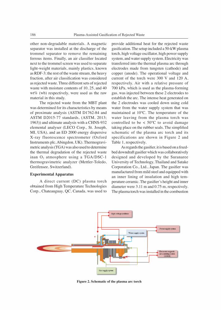
provide additional heat for the rejected waste gasification. The setup included a 50-kW plasma torch, high voltage oscillator, high power supply system, and water supply system. Electricity was transferred into the thermal plasma arc through electrodes made from tungsten (cathode) and copper (anode). The operational voltage and current of the torch were 300 V and 120 A, respectively. Air with a relative pressure of 700 kPa, which is used as the plasma-forming gas, was injected between these 2 electrodes to establish the arc. The intense heat generated on the 2 electrodes was cooled down using cold water from the water supply system that was maintained at 10ºC. The temperature of the water leaving from the plasma torch was controlled to be < 50ºC to avoid damage taking place on the rubber seals. The simplified schematic of the plasma arc torch and its specifications are shown in Figure 2 and Table 1, respectively. As regards the gasifier, it is based on a fixed- bed downdraft gasifier which was collaboratively designed and developed by the Suranaree University of Technology, Thailand and Satake Corporation Co., Ltd., Japan. The gasifier was manufactured from mild steel and equipped with an inner lining of insulation and high tem- perature ceramic. The gasifier’s height and inner diameter were 3.11 m and 0.75 m, respectively. The plasma torch was installed in the combustion
Figure 2. Schematic of the plasma arc torch
187Suranaree J. Sci. Technol. Vol. 22 No. 2; April - June 2015
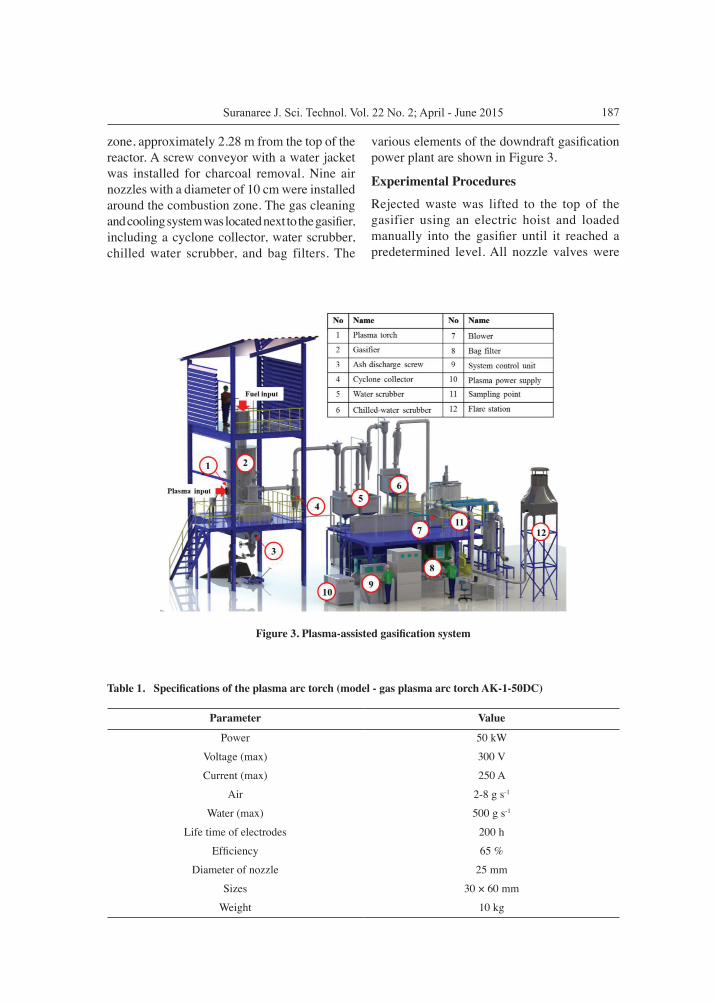
zone, approximately 2.28 m from the top of the reactor. A screw conveyor with a water jacket was installed for charcoal removal. Nine air nozzles with a diameter of 10 cm were installed around the combustion zone. The gas cleaning and cooling system was located next to the gasifier, including a cyclone collector, water scrubber, chilled water scrubber, and bag filters. The
various elements of the downdraft gasification power plant are shown in Figure 3.
Experimental Procedures
Rejected waste was lifted to the top of the gasifier using an electric hoist and loaded manually into the gasifier until it reached a predetermined level. All nozzle valves were
Table 1. Specifications of the plasma arc torch (model - gas plasma arc torch AK-1-50DC)
Parameter Value
Power 50 kW
Voltage (max) 300 V
Current (max) 250 A
Air 2-8 g s-1
Water (max) 500 g s-1
Life time of electrodes 200 h
Efficiency 65 %
Diameter of nozzle 25 mm
Sizes 30 × 60 mm
Weight 10 kg
Figure 3. Plasma-assisted gasification system
Plasma-Assisted Gasification of Rejected Waste188
opened to allow air to flow through the gasifier. The scrubber circulating pump was switched on to start up operations. The rejected waste then was ignited through the plasma torch at the combustion zone. The heat generated in this zone evaporates moisture within the rejected waste in the drying zone and drives the pyrolysis and gasification reactions. Once the gasification process had been completed, the syngas left the gasifier through the gas cleaning and cooling system. Contaminants such as dust, pyrolytic product (tar), and water vapor were initially removed by directing them through a cyclone collector, followed by water scrubbers and a chilled-water scrubber. Because tar vapor condenses at low temperatures, most of the tar was trapped by the cold water in the chilled-water scrubber. Finally, bag filters, which can entrap particulate matters as small as 0.1 mm, were used for the final stage prior to the syngas passing to the flare station. The syngas flow rate for this study was based on the maximum flow rate provided by a blower, which is about 210 m3 h-1, measured using an electronic flow gas meter (Model DIG-SIDO-O, Nippon Flow Cell Co., Ltd., Tokyo, Japan). It was located between the bag filters and the flare station. For each experimental run, the system was operated for 12 h following at least 2 h of system stabilization. The amount of rejected waste to refill the reactor to the predetermined level, with respect to time, was used to calculate the feedstock consumption rate. The ash discharge was controlled to be the same at 14% for all the experiments. In order to monitor the temperature inside the gasifier, 6 K-type thermocouples, installed vertically 0.66, 1.06, 1.46, 1.86, 2.28 and 2.70 m downwards from the top of the gasifier, were used to measure the temperature distribution inside the reactor. The protrusion of the thermocouples from the gasifier wall was 10 cm. The temperatures were measured at intervals of 5 min to record the thermochemical conversion phases: drying, pyrolysis, combustion, and reduction. Gas generated from the rejected waste was directed to an online infrared gas analyzer (model Gasboard-3100, Wuhan Cubic Opto-electronics Co., Ltd., Wuhan, China) to quantify the concentration of the produced gases at the
sampling port located between the bag filters and the flare station. Gas impurities in the form of tar and dust were also determined by drawing the gas using a vacuum pump. In brief, the moisture of the produced gas was gravimetrically measured by passing it through a U-tube containing CaCl2 which was submerged in ice. Then, approximately 300 L of syngas was drawn through a paper filter (GF/B) with a 47 mm diameter. The total tar and dust contents were quantified by drying the paper filter in an oven at 105°C for about 6 h (Bhattacharya et al., 2001). The dried filter then was rinsed with anisole to wash away tar from the filter. The difference in weight of the filter after drying was used to calculate the individual tar and dust contents with respect to the dry gas volume. The data on the syngas composition and the tar and dust contents was collected every 5 min and 30 min, respectively. The performance of the gasification system was evaluated by the following equation (Janajreh et al., 2013):
(1)
where:ηcg = the cold-gas efficiency (%)mreject = the waste reject consumption rate (kg h-1)LHVg = the calorific value of the gas produced (MJ N-1m-3)LHVreject
= the low heating value of the rejected waste (MJ kg-1)Vg = the volume flow rate of the gas produced (Nm3 h-1)Ptorch = the power input for the plasma torch (MJ h-1)
Results and Discussion
Characteristics of the Rejected Waste
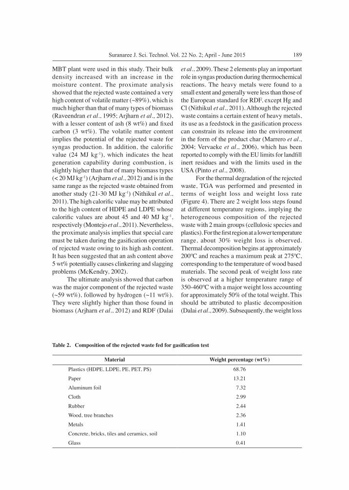
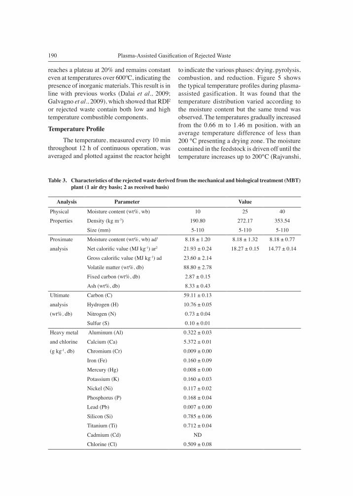
From Table 2, it is found that the major composition of the rejected waste from the MBT plant is plastics (69 wt%), followed by paper (13 wt%). The physical properties, proximate, and ultimate values of the rejected waste are presented in Table 3. Three levels of moisture content obtained from different batches of the
189Suranaree J. Sci. Technol. Vol. 22 No. 2; April - June 2015
MBT plant were used in this study. Their bulk density increased with an increase in the moisture content. The proximate analysis showed that the rejected waste contained a very high content of volatile matter (~89%), which is much higher than that of many types of biomass (Raveendran et al., 1995; Arjharn et al., 2012), with a lesser content of ash (8 wt%) and fixed carbon (3 wt%). The volatile matter content implies the potential of the rejected waste for syngas production. In addition, the calorific value (24 MJ kg-1), which indicates the heat generation capability during combustion, is slightly higher than that of many biomass types (< 20 MJ kg-1) (Arjharn et al., 2012) and is in the same range as the rejected waste obtained from another study (21-30 MJ kg-1) (Nithikul et al., 2011). The high calorific value may be attributed to the high content of HDPE and LDPE whose calorific values are about 45 and 40 MJ kg-1, respectively (Montejo et al., 2011). Nevertheless, the proximate analysis implies that special care must be taken during the gasification operation of rejected waste owing to its high ash content. It has been suggested that an ash content above 5 wt% potentially causes clinkering and slagging problems (McKendry, 2002). The ultimate analysis showed that carbon was the major component of the rejected waste (~59 wt%), followed by hydrogen (~11 wt%). They were slightly higher than those found in biomass (Arjharn et al., 2012) and RDF (Dalai
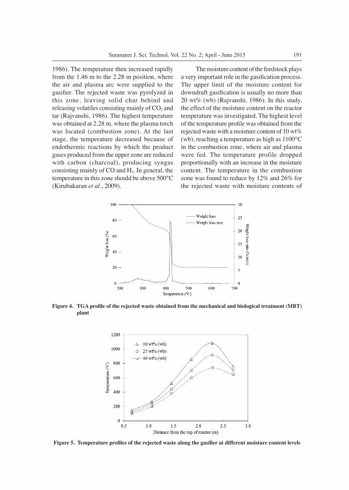
et al., 2009). These 2 elements play an important role in syngas production during thermochemical reactions. The heavy metals were found to a small extent and generally were less than those of the European standard for RDF, except Hg and Cl (Nithikul et al., 2011). Although the rejected waste contains a certain extent of heavy metals, its use as a feedstock in the gasification process can constrain its release into the environment in the form of the product char (Marrero et al., 2004; Vervaeke et al., 2006), which has been reported to comply with the EU limits for landfill inert residues and with the limits used in the USA (Pinto et al., 2008). For the thermal degradation of the rejected waste, TGA was performed and presented in terms of weight loss and weight loss rate (Figure 4). There are 2 weight loss steps found at different temperature regions, implying the heterogeneous composition of the rejected waste with 2 main groups (cellulosic species and plastics). For the first region at a lower temperature range, about 30% weight loss is observed. Thermal decomposition begins at approximately 200ºC and reaches a maximum peak at 275ºC, corresponding to the temperature of wood based materials. The second peak of weight loss rate is observed at a higher temperature range of 350-460ºC with a major weight loss accounting for approximately 50% of the total weight. This should be attributed to plastic decomposition (Dalai et al., 2009). Subsequently, the weight loss
Table 2. Composition of the rejected waste fed for gasification test
Material Weight percentage (wt%)
Plastics (HDPE, LDPE, PE, PET, PS) 68.76
Paper 13.21
Aluminum foil 7.32
Cloth 2.99
Rubber 2.44
Wood, tree branches 2.36
Metals 1.41
Concrete, bricks, tiles and ceramics, soil 1.10
Glass 0.41
Plasma-Assisted Gasification of Rejected Waste190
reaches a plateau at 20% and remains constant even at temperatures over 600ºC, indicating the presence of inorganic materials. This result is in line with previous works (Dalai et al., 2009; Galvagno et al., 2009), which showed that RDF or rejected waste contain both low and high temperature combustible components.
Temperature Profile
The temperature, measured every 10 min throughout 12 h of continuous operation, was averaged and plotted against the reactor height
to indicate the various phases: drying, pyrolysis, combustion, and reduction. Figure 5 shows the typical temperature profiles during plasma-assisted gasification. It was found that the temperature distribution varied according to the moisture content but the same trend was observed. The temperatures gradually increased from the 0.66 m to 1.46 m position, with an average temperature difference of less than 200 °C presenting a drying zone. The moisture contained in the feedstock is driven off until the temperature increases up to 200°C (Rajvanshi,
Table 3. Characteristics of the rejected waste derived from the mechanical and biological treatment (MBT) plant (1 air dry basis; 2 as received basis)
Analysis Parameter Value
Physical Moisture content (wt%, wb) 10 25 40Properties Density (kg m-3) 190.80 272.17 353.54
Size (mm) 5-110 5-110 5-110
Proximate Moisture content (wt%, wb) ad1 8.18 ± 1.20 8.18 ± 1.32 8.18 ± 0.77
analysis Net calorific value (MJ kg-1) ar2 21.93 ± 0.24 18.27 ± 0.15 14.77 ± 0.14
Gross calorific value (MJ kg-1) ad 23.60 ± 2.14
Volatile matter (wt%, db) 88.80 ± 2.78
Fixed carbon (wt%, db) 2.87 ± 0.15
Ash (wt%, db) 8.33 ± 0.43
Ultimate Carbon (C) 59.11 ± 0.13
analysis Hydrogen (H) 10.76 ± 0.05
(wt%, db) Nitrogen (N) 0.73 ± 0.04
Sulfur (S) 0.10 ± 0.01
Heavy metal Aluminum (Al) 0.322 ± 0.03
and chlorine Calcium (Ca) 5.372 ± 0.01
(g kg-1, db) Chromium (Cr) 0.009 ± 0.00
Iron (Fe) 0.160 ± 0.09
Mercury (Hg) 0.008 ± 0.00
Potassium (K) 0.160 ± 0.03
Nickel (Ni) 0.117 ± 0.02
Phosphorus (P) 0.168 ± 0.04
Lead (Pb) 0.007 ± 0.00
Silicon (Si) 0.785 ± 0.06
Titanium (Ti) 0.712 ± 0.04
Cadmium (Cd) ND
Chlorine (Cl) 0.509 ± 0.08
191Suranaree J. Sci. Technol. Vol. 22 No. 2; April - June 2015
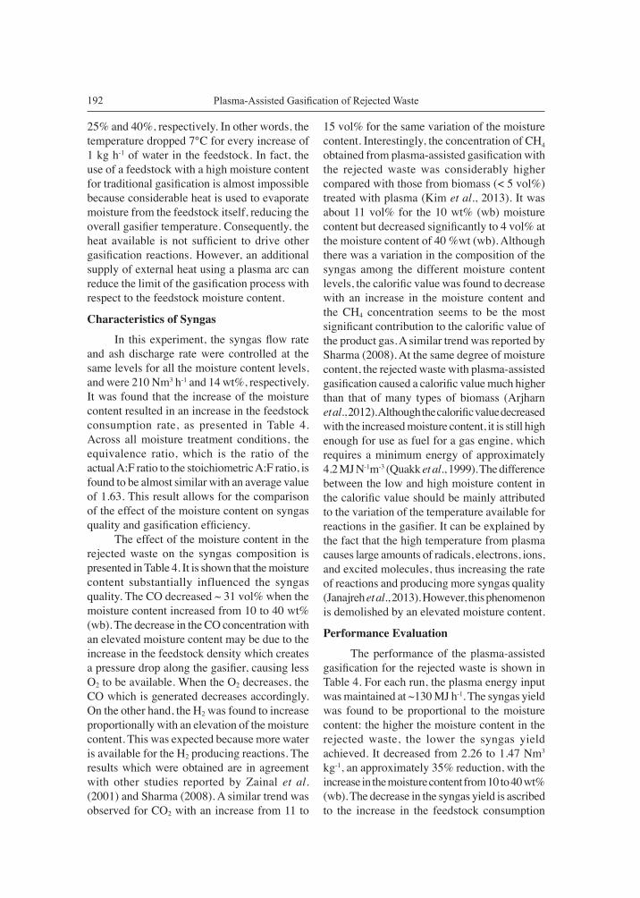
1986). The temperature then increased rapidly from the 1.46 m to the 2.28 m position, where the air and plasma arc were supplied to the gasifier. The rejected waste was pyrolyzed in this zone, leaving solid char behind and releasing volatiles consisting mainly of CO2 and tar (Rajvanshi, 1986). The highest temperature was obtained at 2.28 m, where the plasma torch was located (combustion zone). At the last stage, the temperature decreased because of endothermic reactions by which the product gases produced from the upper zone are reduced with carbon (charcoal), producing syngas consisting mainly of CO and H2. In general, the temperature in this zone should be above 500°C (Kirubakaran et al., 2009).
The moisture content of the feedstock plays a very important role in the gasification process. The upper limit of the moisture content for downdraft gasification is usually no more than 20 wt% (wb) (Rajvanshi, 1986). In this study, the effect of the moisture content on the reactor temperature was investigated. The highest level of the temperature profile was obtained from the rejected waste with a moisture content of 10 wt% (wb), reaching a temperature as high as 1100°C in the combustion zone, where air and plasma were fed. The temperature profile dropped proportionally with an increase in the moisture content. The temperature in the combustion zone was found to reduce by 12% and 26% for the rejected waste with moisture contents of
Figure 4. TGA profile of the rejected waste obtained from the mechanical and biological treatment (MBT) plant
Figure 5. Temperature profiles of the rejected waste along the gasifier at different moisture content levels
Plasma-Assisted Gasification of Rejected Waste192
25% and 40%, respectively. In other words, the temperature dropped 7°C for every increase of 1 kg h-1 of water in the feedstock. In fact, the use of a feedstock with a high moisture content for traditional gasification is almost impossible because considerable heat is used to evaporate moisture from the feedstock itself, reducing the overall gasifier temperature. Consequently, the heat available is not sufficient to drive other gasification reactions. However, an additional supply of external heat using a plasma arc can reduce the limit of the gasification process with respect to the feedstock moisture content.
Characteristics of Syngas
In this experiment, the syngas flow rate and ash discharge rate were controlled at the same levels for all the moisture content levels, and were 210 Nm3 h-1 and 14 wt%, respectively. It was found that the increase of the moisture content resulted in an increase in the feedstock consumption rate, as presented in Table 4. Across all moisture treatment conditions, the equivalence ratio, which is the ratio of the actual A:F ratio to the stoichiometric A:F ratio, is found to be almost similar with an average value of 1.63. This result allows for the comparison of the effect of the moisture content on syngas quality and gasification efficiency. The effect of the moisture content in the rejected waste on the syngas composition is presented in Table 4. It is shown that the moisture content substantially influenced the syngas quality. The CO decreased ~ 31 vol% when the moisture content increased from 10 to 40 wt% (wb). The decrease in the CO concentration with an elevated moisture content may be due to the increase in the feedstock density which creates a pressure drop along the gasifier, causing less O2 to be available. When the O2 decreases, the CO which is generated decreases accordingly. On the other hand, the H2 was found to increase proportionally with an elevation of the moisture content. This was expected because more water is available for the H2 producing reactions. The results which were obtained are in agreement with other studies reported by Zainal et al. (2001) and Sharma (2008). A similar trend was observed for CO2 with an increase from 11 to
15 vol% for the same variation of the moisture content. Interestingly, the concentration of CH4 obtained from plasma-assisted gasification with the rejected waste was considerably higher compared with those from biomass (< 5 vol%) treated with plasma (Kim et al., 2013). It was about 11 vol% for the 10 wt% (wb) moisture content but decreased significantly to 4 vol% at the moisture content of 40 %wt (wb). Although there was a variation in the composition of the syngas among the different moisture content levels, the calorific value was found to decrease with an increase in the moisture content and the CH4 concentration seems to be the most significant contribution to the calorific value of the product gas. A similar trend was reported by Sharma (2008). At the same degree of moisture content, the rejected waste with plasma-assisted gasification caused a calorific value much higher than that of many types of biomass (Arjharn et al., 2012). Although the calorific value decreased with the increased moisture content, it is still high enough for use as fuel for a gas engine, which requires a minimum energy of approximately 4.2 MJ N-1m-3 (Quakk et al., 1999). The difference between the low and high moisture content in the calorific value should be mainly attributed to the variation of the temperature available for reactions in the gasifier. It can be explained by the fact that the high temperature from plasma causes large amounts of radicals, electrons, ions, and excited molecules, thus increasing the rate of reactions and producing more syngas quality (Janajreh et al., 2013). However, this phenomenon is demolished by an elevated moisture content.
Performance Evaluation
The performance of the plasma-assisted gasification for the rejected waste is shown in Table 4. For each run, the plasma energy input was maintained at ~130 MJ h-1. The syngas yield was found to be proportional to the moisture content: the higher the moisture content in the rejected waste, the lower the syngas yield achieved. It decreased from 2.26 to 1.47 Nm3 kg-1, an approximately 35% reduction, with the increase in the moisture content from 10 to 40 wt% (wb). The decrease in the syngas yield is ascribed to the increase in the feedstock consumption

193Suranaree J. Sci. Technol. Vol. 22 No. 2; April - June 2015
rate from 93 to 143 kg h-1. The energy yield, which was calculated as the ratio of syngas energy to its corresponding consumption mass, also showed a similar trend. It reduced considerably, by 62%, for the same range of moisture content. The cold gas efficiency (ηcg) is used to determine the energy efficiency of a gasification process. The value of ηcg decreased from 85.16% at a moisture content of 10 wt% (wb) to 47.96% at a moisture content of 40 wt% (wb). This is expected because partial heat is used to evaporate moisture, thus less heat is available for promoting endothermic gasification (Arjharn et al., 2013). It was found that the traditional gasification process with external heat from a plasma arc caused more or less the same gasification efficiency as those processes without plasma (Arjharn et al., 2012) for biomass and was in the same range for MSW plasma gasification (Zhang et al., 2012).
Tar and Dust Contents
Tar and dust play a crucial role in the gasification process and subsequent applications. High tar and dust contents in the syngas cause a shut-down of gasification facilities due to the blocking and fouling of downstream applications such as turbines and engines, thus requiring post-treatment, maintenance, and complicated cleaning (Cao et al., 2006). Table 5 presents the tar and dust contents in the product gas at different feedstock moisture content levels. They were measured after a series of cleaning units, including water scrubbers, a chilled water scrubber, and bag filters. Increasing the feedstock moisture content from 10 to 40 wt% (wb) led to a significant increase in both the tar and dust contents. Overall, the total tar and dust contents increased approximately 3.7 times for the moisture content
Table 4. Experimental results of the plasma-assisted gasification test
Parameter UnitMoisture content of feedstock (wt%, wb)
10 25 40
Syngas flow rate Nm3 h-1 210.05 ± 2.45
Equivalence ratio (ER) - 0.16 0.16 0.17
Feedstock consumption rate kg h-1 92.8 ± 1.05 110.50 ± 2.10 143 ± 1.50
Ash discharge rate kg h-1 12.95 ± 0.38 15.74 ± 0.38 20.23 ± 0.38
% 13.95 ± 0.43 14.25 ± 0.42 14.15 ± 0.67
Composition dry basis
CO % 12.88 ± 0.11 11.82 ± 0.14 8.90 ± 0.11
H2 % 13.53 ± 0.42 14.29 ± 0.48 15.18 ± 0.42
CH4 % 11.61 ± 0.12 9.25 ± 0.16 4.01 ± 0.11
N2 % 50.53 ± 1.44 50.33 ± 1.57 56.22 ± 1.32
O2 % 0.57 ± 0.08 0.67 ± 0.11 0.95 ± 0.14
CO2 % 10.89 ± 0.45 13.64 ± 0.51 14.74 ± 0. 45
LHV MJ N-1m-3 8.26 ± 0.11 7.25 ± 0.14 4.82 ± 0.12
Syngas yield Nm3 kg-1 2.26 ± 0.03 1.93 ± 0.03 1.47 ± 0.03
Energy yield MJ kg-1 18.68 ± 0.44 13.96 ± 0.53 7.08 ± 0.45
Energy input (feedstock)
MJ h-1 2036.29 ± 2.95 2019.03 ± 2.54 2112.61 ± 2.43
Energy input (plasma power) MJ h-1 129.6 ± 1.52 129.6 ± 1.52 129.6 ± 1.52
Energy output (syngas energy) MJ h-1 1734.08 ± 1.82 1521.99 ± 1.77 1013.13 ± 1.42
Cold-gas efficiency (ηcg) % 85.16 ± 0.21 75.38 ± 0.19 47.96 ± 0.22

Plasma-Assisted Gasification of Rejected Waste194
difference between 10 and 40 wt% (wb). This increase of both tar and dust may be attributed to the decrease of the temperature when increasing the moisture content. Generally, in a gasification system operated at high temperature, a part of the tar and dust is burnt in a high local temperature zone (combustion zone), leaving a certain amount in the syngas stream. However, if the temperature drops, which is the case for rejected waste with a high moisture content, more tar and dust contents inevitably remain unburned in the syngas. The final tar and dust contents, measured after the bag filters, ranged from 1.14 to 5.35 mg N-1 m-3 for moisture contents of 10 and 40 wt% (wb), respectively. Typical tar and dust contents generated from a downdraft gasification system have been reported to range between 50 and 500 mg N-1m-3 (Kaupp and Goss, 1981; Reed and Bryant, 1978), depending on the raw material, gasifier design, experimental conditions, and tar collection methods (Devi et al., 2003). This indicates that the gasification system used in this study can produce very good quality syngas, clean enough to use in a gas engine-generator set (Bhattacharya et al., 2001).
ConclusionsIn this study, rejected waste from an MBT plant was used to produce syngas using a pilot scale plasma-assisted gasification power plant. The effects of the moisture content in the feedstock on various gasification parameters were investigated. Temperatures inside the reactor progressively increased with the decrease of the moisture content. The syngas composition was significantly affected by the moisture content. Calorific values tended to increase as the moisture content decreased from 40 to
10 %wt (wb), with values ranging from 4.82 to 8.26 MJ N-1m-3. The feedstock consumption rate was found to increase with an increase in the moisture content. Performance analyses in terms of syngas yield, energy yield, and gasification efficiency were highest at the moisture content of 10 %wt (wb) but decreased significantly with the increased moisture content. Overall, traditional gasification assisted with a plasma arc can reduce the limits associated with rejected waste properties and can be used to generate quality syngas.
Acknowledgements The authors would like to acknowledge the financial support given by the Office of Research and Project Coordination, Office of the National Research Council of Thailand, Energy Policy and Planning Office, Ministry of Energy, Thailand, and Institute of Research and Development, Suranaree University of Technology, Thailand.
ReferencesArena, U. (2012). Process and technological aspects of
municipal solid waste gasification. A review. Waste Manage., 32:625-639.
Arjharn, W., Hinsui, T., Liplap, P., and Raghavan, G.S.V. (2012). Evaluation of electricity production from different biomass feedstocks using a pilot-scale downdraft gasifier. J. Biobased Mater. Bio., 6(3): 309-318.
Arjharn, W., Hinsui, T., Liplap, P., and Raghavan, G.S.V. (2013). Evaluation of an energy production system from sewage sludge using a pilot-scale downdraft gasifier. Energ. Fuel., 27(1):229-236.
ASTM. (1963). Standard Test Method for Gross Calorific Value of Solid Fuel by the Adiabatic Bomb Calorimeter. ASTM: D2015-77 (Reapproved 1978). ASTM International, West Conshohocken, PA, USA.
Table 5. Tar and dust contents with respect to feedstock moisture content
Moisture content(wt%, wb)
Impurity (mg N-1m-3)
Tar Dust Total
10 0.97 ± 0.01 0.18 ± 0.11 1.14 ± 0.21
25 1.66 ± 0.21 1.47 ± 0.22 3.13 ± 0.30
40 3.26 ± 0.23 2.08 ± 0.24 5.35 ± 0.31
195Suranaree J. Sci. Technol. Vol. 22 No. 2; April - June 2015
ASTM. (2013). Standard Test Method for Chemical Analysis of Wood Charcoal. ASTM: D1762-84. ASTM International, West Conshohocken, PA, USA.
Bhattacharya, S.C., Shwe Hla, S., and Pham, H.-L. (2001). A study on a multi-stage hybrid gasifier engine system. Biomass Bioenerg., 21(6):445-460.
Cao, Y., Wang, Y., Riley, J.T. and Pan, W.-P. (2006). A novel biomass air gasification process for producing tar-free higher heating value fuel gas. Fuel Process. Technol., 87(4):343-353.
Chiemchaisri, C., Charnnok, B., and Visvanathan, C. (2010). Recovery of plastic wastes from dumpsite as refuse-derived fuel and its utilization in small gasification system. Bioresource Technol., 101(5): 1522-1527.
Dalai, A.K., Batta, N., Eswaramoorthi, I., and Schoenau, G.J. (2009). Gasification of refuse derived fuel in a fixed bed reactor for syngas production. Waste Manage., 29(1):252-258.
Devi, L., Ptasinski, K.J., and Janssen, F.J.J.G. (2003). A review of the primary measures for tar elimination in biomass gasification processes. Biomass Bioenerg., 24(2):125-140.
Di Lonardo, M., Lombardi, F., and Gavasci, R. (2012). Characterization of MBT plants input and outputs: a review. Rev. Environ. Sci. Biotechnol., 11:353-363.
Galvagno, S., Casciaro, G., Casu, S., Martino, M., Mingazzini, C., Russo, A., and Portofino, S. (2009). Steam gasification of tyre waste, poplar, and refuse-derived fuel: A comparative analysis. Waste Manage., 29:678-689.
Janajreh, I., Raza, S.S., and Valmundsson, A.S. (2013). Plasma gasification process: Modeling, simulation and comparison with conventional air gasification. Energ. Convers. Manage., 65:801-809.
Kaupp, A. and Goss, J.R. (1981). State of art for small scale (50 kW) to gas producer-engine systems. Final Report to the USDA USFS on Contract No. 53-319R-0-141. University of California, Davis, CA, USA, 278p.
Kim, S.C., Lim, M.S., and Chun, Y.N. (2013). Hydrogen-rich gas production from a biomass pyrolysis gas by using a plasmatron. Int. J. Hydrogen Energ., 38(34): 14458-14466.
Kirubakaran, V., Sivaramakrishnan, V., Nalini, R., Sekar, T., Premalatha, M., and Subramanian, P. (2009). A review on gasification of biomass. Renew. Sust. Energ. Rev., 13(1):179-186.
Kwak, T.H., Maken, S., Lee, S., Park, J.W., Min, B.R., and Yoo, Y.D. (2006). Environmental aspects of gasification of Korean municipal solid waste in a pilot plant. Fuel, 85:2012-2017.
Larson, E.D. (1998). Small-scale gasification-based biomass power generation. Proceedings of the Biomass Workshop; January 12-13, 1998; Chang-chun, Jilin Province, China, p. 1-26.
Li, J., Liao, S., Dan, W., Jia, K., and Zhou, X. (2012). Experimental study on catalytic stream gasification of municipal solid waste for bioenergy production in a combined fixed bed reactor. Biomass Bioenerg., 46:174-180.
Malkow, T. (2004). Novel and innovative pyrolysis and gasification technologies for energy efficient and environmentally sound MSW disposal. Waste Manage., 24:53-79.
Marrero, T.W., McAuley, B.P., Sutterlin, W.R., Morris, J.S., and Manahan, S.E. (2004). Fate of heavy metals and radioactive metals in gasification of sewage sludge. Waste Manage., 24(2):193-198.
McKendry, P. (2002). Energy production from biomass (part 3): gasification technologies. Bioresource Technol., 83:55-63.
Montejo, C., Costa, C., Ramos, P., and Márquez, M.D.C. (2011). Analysis and comparison of municipal solid waste and reject fraction as fuels for incineration plants. Appl. Therm. Eng., 31(13):2135-2140.
Nithikul, J., Karthikeyan, O.P., and Visvanathan, C. (2011). Reject management from a Mechanical Biological Treatment plant in Bangkok, Thailand. Resour. Conserv. Recy., 55(4):417-422.
Ojha, A., Reuben, A.C., and Sharma, D. (2012). Solid Waste Management in Developing Countries through Plasma Arc Gasification- An Alternative Approach. APCBEE Procedia, 1:193-198.
Pinto, F., André, R.N., Lopes, H., Dias, M., Gulyurtlu, I., and Cabrita, I. (2008). Effect of experimental conditions on gas quality and solids produced by sewage sludge cogasification. 2. sewage sludge mixed with biomass. Energ. Fuel., 22(4):2314-2325.
Quakk, P., Knoef, H., and Stassen, H. (1999). Energy from Biomass: a Review of Combustion and Gasification Technologies. World Bank Publica-tions, Washington, DC, USA, 78p.
Rajvanshi, A.K. (1986). Biomass gasification. In: Alternative Energy in Agriculture. Goswami, Y.D., (ed). CRC Press, LLC, Boca Raton, FL, USA, p. 83-102.
Raveendran, K., Ganesh, A., and Khilar, K.C. (1995). Influence of mineral matter on biomass pyrolysis characteristics. Fuel, 74:1812-1822.
Reed, T. and Bryant, B. (1978). Densified Biomass: A New Form of Solid Fuel. Solar Energy Research Institute, Golden, CO, USA, 47p.
Rutberg, P.G., Bratsev, A.N., Kuznetsov, V.A., Popov, V.E., Ufimtsev, and A.A., Shtengel, S.V. (2011). On efficiency of plasma gasification of wood residues. Biomass Bioenerg., 35(1):495-504.
Seggiani, M., Vitolo, S., Puccini, M., and Bellini, A. (2012). Cogasification of sewage sludge in an updraft gasifier. Fuel, 93:86-91.
Sharma, A.K. (2008). Equilibrium modeling of global reduction reactions for a downdraft (biomass) gasifier. Energ. Convers. Manage., 49(4):832-842.

Plasma-Assisted Gasification of Rejected Waste196
Velis, C.A., Longhurst, P.J., Drew, G.H., Smith, R., and Pollard, S.J.T. (2010). Production and quality assurance of solid recovered fuels using me-chanical—biological treatment (MBT) of waste: A comprehensive assessment. Crit. Rev. Env. Sci. Tec., 40(12):979-1105.
Vervaeke, P., Tack, F.M.G., Navez, F., Martin, J., Verloo, M.G., and Lust, N. (2006). Fate of heavy metals during fixed bed downdraft gasification of willow wood harvested from contaminated sites. Biomass Bioenerg., 30(1):58-65.
Yoon, S.J., Yun, Y.M., Seo, M.W., Kim, Y.K., Ra, H.W., and Lee, J.-G. (2013). Hydrogen and syngas production from glycerol through microwave plasma gasification. Int. J. Hydrogen Energ., 38(34):14559-14567.
Zainal, Z.A., Ali, R., Lean, C.H., and Seetharamu, K.N. (2001). Prediction of performance of a downdraft gasifier using equilibrium modeling for different biomass materials. Energ. Convers. Manage., 42(12):1499-1515.
Zhang, Q., Dor, L., Fenigshtein, D., Yang, W., and Blasiak, W. (2012). Gasification of municipal solid waste in the Plasma Gasification Melting process. Appl. Energ., 90(1):106-112.
Related Documents