1.INTRODUCTION The term plasma antenna has been applied to a wide variety of antenna concepts that incorporate some use of an ionized medium. In the vast majority of approaches, the plasma, or ionized volume, simply replaces a solid conductor. A highly ionized plasma is essentially a good conductor, and therefore plasma filaments can serve as transmission line elements for guiding waves, or antenna surfaces for radiation. The concept is not new. A patent entitled “Aerial Conductor for Wireless Signaling and Other Purposes” was awarded to J. Hettinger in 1919. Early practical examples of the technology used discharge tubes to contain the plasma and are referred to as ionized gas plasma antennas. Ionized gas plasma antennas can be turned on and off and are good for stealth and resistance to electronic warfare and cyber attacks. Ionized gas plasma antennas can be nested such that the higher frequency plasma antennas are placed inside lower frequency plasma antennas. Higher frequency ionized gas plasma antenna arrays can transmit and receive through lower frequency ionized gas plasma antenna arrays. This means that the ionized gas plasma antennas can be co-located and ionized gas plasma antenna arrays can be stacked. Ionized gas plasma antennas can eliminate or reduce co-site interference. Smart ionized gas plasma antennas use plasma physics to shape and steer the antenna beams without the need of phased arrays. Satellite signals can be steered and/or focused in the reflective or refractive modes using 1

Welcome message from author
This document is posted to help you gain knowledge. Please leave a comment to let me know what you think about it! Share it to your friends and learn new things together.
Transcript
1. INTRODUCTION
The term plasma antenna has been applied to a wide variety of antenna concepts that
incorporate some use of an ionized medium. In the vast majority of approaches, the plasma,
or ionized volume, simply replaces a solid conductor. A highly ionized plasma is essentially
a good conductor, and therefore plasma filaments can serve as transmission line elements for
guiding waves, or antenna surfaces for radiation. The concept is not new. A patent entitled
“Aerial Conductor for Wireless Signaling and Other Purposes” was awarded to J. Hettinger in
1919.
Early practical examples of the technology used discharge tubes to contain the plasma and are
referred to as ionized gas plasma antennas. Ionized gas plasma antennas can be turned on and
off and are good for stealth and resistance to electronic warfare and cyber attacks. Ionized gas
plasma antennas can be nested such that the higher frequency plasma antennas are placed
inside lower frequency plasma antennas. Higher frequency ionized gas plasma antenna arrays
can transmit and receive through lower frequency ionized gas plasma antenna arrays. This
means that the ionized gas plasma antennas can be co-located and ionized gas plasma antenna
arrays can be stacked. Ionized gas plasma antennas can eliminate or reduce co-site
interference. Smart ionized gas plasma antennas use plasma physics to shape and steer the
antenna beams without the need of phased arrays. Satellite signals can be steered and/or
focused in the reflective or refractive modes using banks of plasma tubes making unique
ionized gas satellite plasma antennas. The thermal noise of ionized gas plasma antennas is
less than in the corresponding metal antennas at the higher frequencies. Solid state plasma
antennas (also known as plasma silicon antennas) with steerable directional functionality that
can be manufactured using standard silicon chip fabrication techniques are now also in
development. Plasma silicon antennas are candidates for use in WiGig (the planned
enhancement to Wi-Fi), and have other potential applications, for example in reducing the
cost of vehicle-mounted radar collision avoidance systems.
1
2. Fundamental Plasma Theory
A plasma can be generated from neutral molecules that are separated into negative electrons
and positive ions by an ionization process (e.g., laser heating or spark discharge). The
positive ions and neutral particles are much heavier than the electrons, and therefore the
electrons can be considered as moving through a continuous stationary fluid of ions and
neutrals with some viscous friction. Furthermore, the propagation characteristics of
electromagnetic (EM) waves in a uniform ionized medium can be inferred from the equation
of motion of a single “typical” electron. Such a medium is called a “cold plasma.” This model
would be rigorous if the ionized medium was comprised entirely of electrons that do not
interact with the background particles (neutrals and ions) and posses thermal speeds that are
negligible with respect to the phase velocity of the EM wave.
In the absence of a magnetic field, the important parameters for a cold plasma are the electron
density Ne electrons/m3 and the collision frequency n /m3. The complex relative dielectric
constant of the plasma is given by [2-5]
Assuming a time harmonic wave with an e^(jwt) time dependence, a x-polarized
electromagnetic plane wave propagating in the +z direction has the form
2

where is the conventionally defined propagation constant. The real and imaginary parts of
the propagation constant are the attenuation and phase constants, respectively
For the special case of negligible collisions, n 0 , the corresponding propagation constant is
The intrinsic impedance of the plasma medium is
Figure 1 shows the magnitude of the reflection coefficient at an infinite plane boundary
between plasma and free space, which is given by the formula
3

The impedance of free space is ho 377 ohms. From the figure it is evident that at
frequencies below the plasma frequency, the plasma is a good reflector.
Figure 1: Reflection coefficient for a plane wave normally incident on a sharp
plasma/air boundary ( Ne 11012 /m3, n 0 , dashed line is the plasma frequency, fp
8.9 MHz).
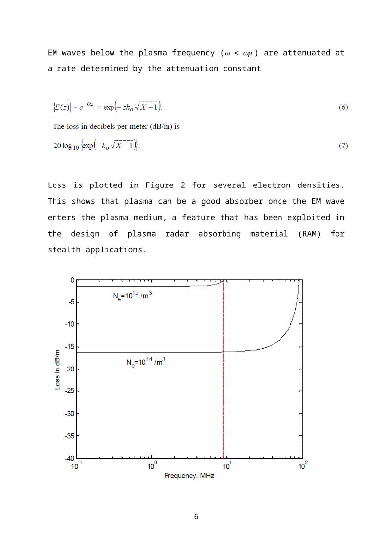
EM waves below the plasma frequency ( w wp ) are attenuated at a rate determined by the
attenuation constant
4

Loss is plotted in Figure 2 for several electron densities. This shows that plasma can be a
good absorber once the EM wave enters the plasma medium, a feature that has been exploited
in the design of plasma radar absorbing material (RAM) for stealth applications.
Figure 2: Loss in dB/m below the plasma frequency for several electron densities(n = 0).
For neutral plasma the positive and negative charges are uniformly distributed, so that on a
macroscopic scale it is electrically neutral. Plasma oscillations (or space-charge oscillations)
can arise when a disturbance causes a displacement of the charges, which sets up an electric
field that acts to restore them to their equilibrium positions. However, inertia carries the
5
charges back past their neutral positions and an opposite electric field is set up. In the absence
of collisions (damping) the back and forth plasma oscillations continue indefinitely.
Plasma oscillations generally do not propagate in a cold plasma unless it has a drift velocity,
or is finite and has normal modes that arise from boundary conditions. An example of the
second case is a plasma column having a sharp boundary with a vacuum or dielectric. In
addition to modifying the EM wave, a longitudinal wave arises, analogous to a sound wave in
non-ionized gas. These waves are variously referred to as plasma, electrostatic, space-charge,
or electro-acoustical waves.
In a “warm plasma” the electron thermal velocity cannot be ignored, but non-relativistic
mechanics still apply. The spatial variations (gradients) in temperature and density over a
wavelength drive the particle currents, along with the electric field of the EM wave passing
through. Generally, for antenna applications, a cold plasma can be assumed.
When a magnetic field or density gradient is present, space-charge waves may couple to EM
waves. Electrons with thermal speeds close to the phase velocity of the EM wave can
exchange energy with the wave by the processes of Landau damping and Cerenkov radiation.
These processes are exploited in some commonly used devices such as linear accelerators and
traveling-wave tubes.
3. Plasma Generation and Containment
For antenna applications the plasma must be maintained in precise spatial distributions, such
as filaments, columns, or sheets. The plasma volume can be contained in an enclosure (tube)
or suspended in free space. Compositions that may be used to form plasma in a tube include
gases of neon, xenon, argon, krypton, hydrogen, helium, and mercury vapor. Energizing the
plasma can be accomplished with electrodes, fiber optics, microwave signals, lasers, RF
heating, or electromagnetic couplers. The tube confines the gas and prevents diffusion. The
radiation pattern is controlled by parameters such as plasma density, tube shape, and current
distribution. Some examples are shown in Figure 3.
6
Figure 3: Examples of a plasma loop and reflector antenna using tubes
The degree of ionization of a gas is given as a percentage
where No is the density of neutral molecules. For example, a standard fluorescent tube has an
ionization of about 10^(5) with No 1016 / cm3 and Ne 1011 / cm3. The conductivity of a
gas reaches half of its maximum at about 0.1% ionization, and essentially has its maximum
value at1% ionization (i.e., the conductivity at 1% ionization is nearly the same as at 100%
ionization).Strong ionization refers to values on the order of 10^(-4) and greater.
A conventional tube has the disadvantage of requiring two or more contacts (electrodes) for
applying the ionizing potential. As an alternative, a surface wave can be used to excite the
plasma from a single end. The surface space-charge wave is electro-mechanical in nature. A
time-harmonic axial electric field is applied a one end of the plasma column. Charges are
displaced and restoring electric fields are set up in response to the applied field. The charges
remain balanced in the interior of the plasma, but the electric field causes a deformation of
the plasma surface that results in a surface charge layer as shown in Figure 4. The coaxial
device that has been developed to ionize a plasma column based on this principle is the
Surfatron.
7

Figure 4: Distribution of the charges and fields for a surface space-charge wave
Other types of surface wave launching methods have been developed that are more compact
than the Surfatron. One of them is by means of a helicon wave . Helicon waves are a type of
whistler wave, which are circularly polarized and require the presence of a magnetic field.
For a cylinder, the magnetic field is axial and the helicon waves are modes of the bounded
system. Helicon excitation is generally more complicated than surface wave excitation, but
can be applied to electrically short columns, and thus results in more compact hardware at
low frequencies.
Figure 5: Linear plasma antenna excited at one end by a surface wave
8

Plasma surfaces can be suspended in free space to serve as antenna elements. Ionizing a trail
in the atmosphere requires special techniques. High ionization concentrations absorb laser
energy, and at some point the ionization tail becomes opaque, thereby limiting the length.
Several proposed methods use a laser beam (usually pulsed) to establish a low ionization
path, and then subsequent power is applied to achieve intense ionization. Densities of 10^(19)
/ cm3 have been predicted, resulting in a conductivity of a few ohms per meter.
An ionization path in air suffers beam wander due to fluctuations in temperature, density, and
wind along its length. It is necessary to frequently extinguish the path and re-establish one
that is straight and concentrated. This is one advantage of using a pulsed laser, another being
the higher peak power that is achievable over a continuous wave (CW) laser.
Two important parameters of a plasma antenna are the time required for complete ionization,
and the decay time once the excitation is removed. The latter is determined by recombination
processes, the most important of which is an electron attaching itself to a positive ion to form
a neutral molecule. Typical decay times are on the order of tens to hundreds of microseconds.
4. Antenna and Transmission Line Applications
This section describes several antenna and transmission line concepts that incorporate
plasmas.
4.1 Plasma Mirrors (Reflectors) and Lenses
Figures 6 and 7 depict reflector antennas that use a plasma sheet in place of a solid conductor
as the reflecting surface. The reflections actually occur within the plasma, not at an abrupt
interface as they do for a metal reflector. For the purpose of ray tracing the reflection is
considered to occur at a “critical surface” that lies somewhere inside of the plasma (similar to
the virtual reflection point when tracing rays through the ionosphere). The advantages of
these antennas are rapid inertia-less two-dimensional scanning, frequency selectivity by
setting the plasma parameters, and potential wideband frequency performance.
9

In one approach, a laser beam and optics generate a reflecting surface by using a sequence of
line discharges that diffuse together to form a sheet of plasma. Curvature can be obtained in
one dimension (i.e., a singly curved reflector).
A high quality plasma reflector must have a critical surface that can be consistently
reproduced and is stable over the transmission times of interest. When the plasma is turned
off, its decay time will limit how fast the reflecting surface can be moved. Turn-on and turn-
off times of 10 microseconds have been achieved.
Above the plasma frequency, its shape and dielectric properties can be designed to act as a
lens. For example, a column with circular cross section and varying radial electron density
can be used to scan a beam passing through it. This concept has been demonstrated using a
helicon wave to excite the plasma. The frequency of the deflected beam was 36 GHz, the
peak density approximately 710^(18) /m3, and the insertion loss ~2.0 dB. The sweep time for
a 30 degree scan was 200 microseconds, which was limited by the decay rate of the plasma.
Figure 9 shows a comparison of radiation patterns from plasma and metal reflector antennas.
The plasma antenna shows lower side lobes, especially at wide angles, due to its higher
surface resistivity compared to a solid conductor.
Figure 6: Plasma mirror using a laser
10

Figure 8: Plasma mirror using a chamber (tube)
Figure 8: Plasma reflector
11

Figure 9: Comparison of radiation patterns from plasma (blue/dots) and metal (red)
reflectors
4.2 Linear and Loop Antennas with Plasma Enclosures
The first plasma antenna concepts were essentially linear antennas with conductors replaced
by plasmas. The basic concept is illustrated in Figure 10 for a loop-shaped antenna . The gas
can be ionized using electrodes with sufficient voltage, or by using an EM field to excite the
gas.
4.2.1 Ionization Using Electrodes
Figures 10 and 11 show two of the many designs that incorporate closed tubes of gas excited
by voltages applied to electrodes. Figure 11 is reconfigurable in that one or more plasma
paths can be excited. Different paths would be used in different frequency bands. The gas
12

contained in a tube can be ionized by lasers or high power microwave beams, as illustrated in
Figure 12.
Figure 10: Loop antenna
Figure 11: Antenna that can be reconfigured by selecting one of multiple plasma paths
(dashed lines)
13
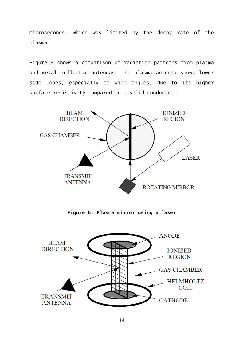
Figure 12: Ionization of a tube of gas (“LOAD”) using standoff lasers
4.2.2 Ionization Using an Electromagnetic Field
It is desirable to have only a single electrode in order to minimize the scattering and
interference of the antenna feed and support structure with the radiated or received EM field.
A surface wave can be used to excite a tube of gas from one end, as shown in Figure 13. The
electric field in the gap excites a surface space-charge wave that propagates down the walls
of the tube and eventually ionizes the gas inside. Figure 14 shows a HF monopole that
incorporates surface wave excitation. The noise has been shown to be comparable to that of a
metal antenna, as shown in the plots of Figure 15.
14

Figure 13: The Surfatron feed. Left: operational principle. Right: hardware
Implementation
Figure 14: An operational HF monopole with surface wave excitation
15

Figure 15: Comparison of the noise spectra for a surface wave driven plasma antenna
and a metal antenna. The vertical scale is in dB
4.3 Linear Antennas and Transmission Lines by Ionizing the Atmosphere
Linear plasma filaments can be generated by ionizing the atmosphere. As discussed
previously, when trying to establish a highly ionized path from the source, the problem of
opacity due to absorption occurs. There are two approaches that avoid this problem. One is to
ionize a path using multiple lasers sequentially focussed to points in space (Figure 16). The
second approach, illustrated in Figure 17, uses a laser (usually pulsed) to establish a low
ionization path, and then subsequent power is applied to achieve intense ionization over the
entire path.
Early patents proposed using ionized paths in the atmosphere for information transmission
(i.e., as transmission lines) or discharging clouds to prevent lightning strikes. Figure 18
shows one proposed concept for discharging a cloud. Parallel paths could be used as a two
wire transmission line, or a surface wave mode could be used with a single ionized path.
16

Figure 16: Ionization of a path in the atmosphere using multiple lasers sequentially
focussed to points in space
Figure 17: Multiple stage ionization of an atmospheric path using a laser
4.4 Plasma Radiation
Several proposed antenna concepts use the plasma space-charge waves to couple to the EM
wave. In Figure 19(a) blocks 15 and 20 represent oppositely directed lasers that are fired
alternately. Each time the laser is fired, a pulse train is transmitted. The resonant frequency of
the plasma in the tube is the transmit frequency. As depicted in Figure 19(b), the oppositely
directed photon beams produce an alternating electric current in the plasma that radiates.
17

Figure 18: Method of discharging a cloud using a conductive path from a laser
Figure 19: Plasma antenna with currents generated by opposed photon beams.
(a) System block diagram, and (b) alternating current vectors due to the interaction of
the oppositely directed laser beams.
18

Figure 20 shows a plasma antenna with multiple tubes. Various possible tube configurations
and combinations of external magnetic fields, temperature gradients, and electric potentials
can be used to change the shape and density of the plasma, allowing it to radiate with the
desired gain and radiation pattern.
Figure 20: Multiple tube plasma antenna. Points 16 are electrodes; 14 and 12 are tube
walls
5. Advantages and Disadvantages
Plasma antennas possess a number of advantages over metal antennas, including:
As soon as the plasma generator is switched off, the plasma returns to a non
conductive gas and therefore becomes effectively invisible to radar.
They can be dynamically tuned and reconfigured for frequency, direction, bandwidth,
gain and beamwidth, so replacing the need for multiple antennas.
They are resistant to electronic warfare.
19

At satellite frequencies, they exhibit much less thermal noise and are capable of faster
data rates.
Table
Property Advantages Disadvantages/Limitations
“Turn-on/turn-off” Reduced RCS
Reduced interference
and ringing
Ionization and decay
times limit scanning
Re-configurable Change shape to control
pattern and bandwidth
Change plasma
parameters
Plasma volumes must be
stable and repeatable
Plasma generator
(Ionizer)
Glow discharge increases
visible signature
Good RF coupling for
electrically small antennas
Frequency selectivity
Ionizer adds weight and
volume
Ionizer increases power
consumption
Confined plasma
(tubes)
Frequency selectivity
Stable and repeatable
Efficient
Not durable or flexible
Atmospheric path Flexibility in length and
direction of path
Higher ionization energy
than for a tube
6. References
20

1. J. Hettinger, “Aerial Conductor for Wireless Signaling and Other Purposes,” Patent
number 1,309,031, July 8, 1919.
2. V. L. Ginzburg, The Propagation of Electromagnetic Waves in Plasmas, Pergamon Press,
1970.
3. J. Drummond, Plasma Physics, McGraw-Hill, 1961.
4. Plasma Antenna Center for Remote Sensing, accessed 2010-12-14.
5. M. Heald and C. Warton, Plasma Diagnostics with Microwaves, Krieger Publishing
Co.,1978.
6. Plasma Antennas: Survey of Techniques and the Current State of the Art D C Jenn,
published 2003-09-29, accessed 2010-10-15.
7. Advances in Plasma Antenna Design Alexeff, I et al., Tennessee University, ISSN: 0730-
9244, ISBN 0-7803-9300-7, published 2007-05-15, accessed 2010-12-14
21
Related Documents