PAVEMENT DESIGN PLANNING SCHEME POLICY

Welcome message from author
This document is posted to help you gain knowledge. Please leave a comment to let me know what you think about it! Share it to your friends and learn new things together.
Transcript

PAVEMENT DESIGN
PLANNING SCHEME POLICY

Planning scheme policy – pavement design v1.1 Page 1
Planning scheme policy – pavement design
Table of contents Amendment history .......................................................................................................................... 2
1 Introduction ...................................................................................................................................... 3 1.1 Application ........................................................................................................................... 3 1.2 Relationship with planning scheme ..................................................................................... 3 1.3 Purpose ............................................................................................................................... 3 1.4 Referenced documents ....................................................................................................... 3
2 Pavement design criteria – design variables ................................................................................... 5 3 Design traffic .................................................................................................................................... 7
3.1 General ................................................................................................................................ 7 3.2 Subgrade evaluation ........................................................................................................... 9 3.3 Environment ...................................................................................................................... 10 3.4 Pavement and surfacing materials .................................................................................... 10
4 Pavement thickness design ........................................................................................................... 11 4.1 Pavement structure – general ........................................................................................... 11 4.2 Unbound granular flexible pavements (bituminous surface) ............................................. 13 4.3 Flexible pavements containing bound layers (bituminous surfaced) ................................ 13 4.4 Rigid pavements................................................................................................................ 13
5 Surfacing design ............................................................................................................................ 14 5.1 Choice of surface types ..................................................................................................... 14 5.2 Sprayed bituminous seals (chip seals).............................................................................. 14 5.3 Bituminous micro surfacing (cold overlay) ........................................................................ 14 5.4 Asphaltic concrete ............................................................................................................. 15
6 Documentation – design criteria and calculations ......................................................................... 15

Planning scheme policy – pavement design v1.1 Page 2
Amendment history This planning scheme policy commenced on 24 July 2017 as part of the Mackay Region Planning Scheme 2017. Amendments since this date are listed in the below table.
Version number
Amendment title Summary of amendment Date adopted and commenced
1.1 Planning scheme policy amendment 3
This amendment updated references, standards, and requirements to reflect modern practice.
Adopted 10 February 2021 Commenced 1 March 2021
1.0 Planning scheme administrative amendment 6, and Planning scheme policy administrative amendment 1
This amendment removed the planning scheme policies from Schedule 6 of the Mackay Region Planning Scheme 2017 and placed them in individual PDFs on Council’s website. This amendment introduced standardised formatting, introductory sections and explanatory information regarding intent and legislative relationship for this planning scheme policy. It also updated numbering and cross references.
Adopted 11 December 2019 Commenced 3 February 2020

Planning scheme policy – pavement design v1.1 Page 3
1 Introduction 1.1 Application
This planning scheme policy supports the Mackay Region Planning Scheme 2017 by providing information on: how to achieve compliance with assessment benchmarks; supporting information/studies required; and/or actions required under the development assessment process. This planning scheme policy has been made by Mackay Regional Council in accordance with Chapter 2, Part 3, Division 2 of the Planning Act 2016.
1.2 Relationship with planning scheme
Mackay Region Planning Scheme 2017 refers to this planning scheme policy in assessment benchmarks in the following code/s or any other relevant part of the scheme:
(a) Table 9.4.1.3.A – General development requirements code (b) Table 9.4.3.3.A – Reconfiguring a lot code
1.3 Purpose The purpose of this planning scheme policy is to: 1. Set guidelines for the design of road pavement to meet the required design life, based on the
subgrade strength, traffic loading and environmental factors, and including the selection of appropriate materials for subgrade, sub-base, base and wearing surface.
2. Ensure that road pavement designs select appropriate pavement and surfacing materials, types,
layer thicknesses and configurations to ensure that the pavement performs adequately and requires minimal maintenance under the anticipated traffic loading for the design life adopted.
3. Set out procedures for the design of the following forms of surfaced road pavement construction:
(a) Flexible pavements consisting of unbound materials;
(b) Flexible pavements that contain one or more bound layers, including pavements;
(c) Containing asphalt layers other than thin asphalt wearing surfaces;
(d) Rigid pavements (i.e. concrete pavements). The design of unsealed (gravel) pavements will only be allowed for low trafficked rural access roads in isolated areas where explicit prior approval has been given by Council. Dimensions for formations and pavement widths in these scenarios will be consistent with Council’s road hierarchy requirements for Average Daily Traffic Volumes less than 150 vpd and in accordance with the IPWEAQ Lower Order Road Design Guidelines for lower volumes roads. Pavement designs for both categories of roads will be in accordance with the requirements of the IPWEAQ Lower Order Road Design Guidelines.
1.4 Referenced documents (a) Council guidelines and specifications:
(i) Planning scheme policy – geometric road design (ii) Planning scheme policy – subsurface drainage design (iii) Construction standard C242 – Flexible pavements

Planning scheme policy – pavement design v1.1 Page 4
(iv) Construction standard C244 – Sprayed bituminous surfacing (v) Construction standard C245 – Asphaltic concrete (vi) Construction standard C247 – Mass concrete sub base (vii) Construction standard C248 – Plain or reinforced concrete base (viii) Construction standard C249 – Steel fibre reinforced concrete base (ix) Construction standard C254 – Segmental paving (x) Construction standard C255 – Bituminous micro surfacing (xi) D20 Drawings and Documentation Guideline -
https://www.mackay.qld.gov.au/__data/assets/pdf_file/0005/13964/D20.pdf
(b) DTMR Specifications MRTS05 Unbound Pavements MRTS07A Insitu Stabilised Subgrades using Quicklime or Hydrated Lime MRTS07B Insitu Stabilised Pavements using Cement or Cementitious Blends MRTS07C Insitu Stabilised Pavements using Foamed Bitumen MRTS08 Plant-Mixed Heavily Bound (Cemented) Pavements MRTS09 Plant-Mixed Pavement Layers Stabilised Using Foamed Bitumen MRTS10 Plant-Mixed Lightly Bound Pavements MRTS11 Sprayed Bituminous Surfacing (Excluding Emulsion) MRTS12 Sprayed Bituminous Emulsion Surfacing MRTS13 Bituminous Slurry Surfacing MRTS17 Bitumen and Multigrade Bitumen MRTS18 Polymer Modified Binder (including Crumb Rubber) MRTS19 Cutter Oils MRTS20 Cutback Bitumen MRTS21 Bituminous Emulsion MRTS22 Supply of Cover Aggregate MRTS23 Supply and Delivery of Quicklime and Hydrated Lime for Road Stabilisation MRTS30 Asphalt Pavements MRTS32 High Modulus Asphalt (EME2) MRTS35 Recycled Material Blends for Pavements MRTS38 Pavement Drains MRTS39 Lean Mix Concrete Sub-base for Pavements MRTS40 Concrete Pavement Base MRTS42 Supply of Wax Emulsion Curing Compound for Concrete MRTS57 Geotextiles for Paving Applications MRTS58 Subgrade Reinforcement using Pavement Geosynthetics MRTS101 Aggregates for Asphalt MRTS102 Reclaimed Asphalt Pavement Material MRTS103 Fillers for Asphalt MRTS104 Retarding Pavement Reflective Cracking using Asphalt Geosynthetics DTMR Standard Drawings
(c) MRC Supplementary Specifications -
https://www.mackay.qld.gov.au/business/planning_and_development/design_and_construction_requirements/design_guidelines2
(d) Queensland authorities:
(i) State Planning Policy
(e) Council documents (i) External Documents Register -https://www.mackay.qld.gov.au/__data/assets/pdf_file/0003/253380/External_Document_Registry_for_Technical_Services_2019_002.pdf (ii) Drawings - https://www.mackay.qld.gov.au/business/planning_and_development/design_and_construction_requirements/standard_drawings/roads (iii) Planning Scheme Road hierarchy overlay - https://www.mackay.qld.gov.au/road_hierarchy_overlay

Planning scheme policy – pavement design v1.1 Page 5
(iv) Road Hierarchy Documentation and Acceptable Cross-sections - https://www.mackay.qld.gov.au/business/planning_and_development/design_and_construction_requirements/road_hierarchy_plans_and_cross-sections
(f) Other: (i) Australian Road Research Board (2005) Sealed local roads manual; (ii) Australian Road Research Board (2005) Unsealed local roads manual; (iii) Australian Road Research Board (2020) – Best Practice Guide – Materials (iv) Australian Road Research Board (2020) – Best Practice Guide – Sealed Roads (v) Australian Road Research Board (2020) – Best Practice Guide – Unsealed Roads (vi) AustRoads – Guide to Pavement Technology
Part 1: Introduction to Pavement Technology Part 2: Pavement Structural Design Part 3: Pavement Surfacings Part 4: Pavement Materials Part 4A: Granular Base and Sub Base Materials Part 4B: Asphalt Part 4C: Materials for Concrete Road Pavements Part 4D: Stabilised Materials Part 4E: Recycled Materials Part 4F: Bituminous Binders Part 4G: Geotextiles and Geogrids Part 4I: Earthworks Materials Part 4J: Aggregate and Source Rock Part 4K: Seals Part 4L: Stabilising Binders Part 5: Pavement Evaluation and Treatment Design (PDF | online being built) Part 6: Unsealed Pavements Part 7: Pavement Maintenance Part 8: Pavement Construction Part 10: Sub-Surface Drainage
(vii) Think Brick Australia – Clay Paving Manual; (viii) Department of Transport and Main Roads, Pavement Rehabilitation Manual (ix) Department of Transport and Main Roads, Pavement Design Supplement (x) Department of Transport and Main Roads, Technical Notes - Pavements, materials
and geotechnical (xi) Department of Transport and Main Roads, Guideline - Structural design procedure of
pavements on lime stabilised subgrades guideline (xii) IPWEAQ – Lower Order Road Design Guidelines
2 Pavement design criteria – design variables
Regardless of the type of road pavements proposed, the design of the pavement shall involve consideration of the following six input variables: (a) design traffic; (b) the current and future hierarchy of the surrounding transport network and impacts of the
proposed project on it; (c) subgrade evaluation; (d) environment; (e) pavement and surfacing materials; and (f) construction and maintenance considerations.

Planning scheme policy – pavement design v1.1 Page 6
A suitably qualified and experienced professional engineer (RPEQ), using an acceptable approach outlined in this Guideline shall determine the road pavement thickness, material types and pavement configuration. For pavement designs in general the Designer should ensure that the pavement design structure does not negate the ability for rehabilitation of the pavement at the end of its initial design life. A range of pavement options are to be considered and the most cost-effective option for the design life is to be selected. For example, unbound granular base and sub-base structures enable rehabilitation works to be undertaken on the pavement structure where stabilised base and sub-base often negate this option. Should pavement designs be provided such that pavement structures are not conducive with rehabilitation of the pavement materials Council will require a “whole of life” cost analysis to prove the pavement selected is the most cost-effective option. Together with consideration of the various alternative pavement designs for the project the Designer shall provide an economic analysis of the alternative designs in accordance with Section 10 of Austroads – Guide to Pavement Technology Part 2. The economic assessment shall consider “whole of life” cost analysis for the pavement with the selected option for construction being that which results in the lowest present worth of costs. The service provided by contributed assets ultimately becomes the responsibility of the Council to continue to deliver. To support this delivery, Council may require that during the design phase, a life cycle approach be adopted that considers the ongoing management obligations of the asset.
(1) The required levels of service for contributed assets should be met in the most cost-effective way, and therefore infrastructure should be provided in a manner which maximises resource efficiency and minimises whole of life cycle costs.
(2) Early identification of costs enables effective decisions to be made in balancing performance, reliability, maintainability, maintenance support and other goals against life cycle costs. Decisions made early in an asset’s life cycle, for example during the design phase, have a much greater influence on reducing life cycle costs than those made post-handover.
(3) The preparation of a life cycle management plan and funding options may be requested for those proposed contributed assets that are considered over and above the level of service represented by the standards contained in this planning scheme policy.
(4) For these assets to be acceptable to Council, the lifecycle costing of the proposed asset needs to be evaluated to determine: -
(a) maintenance and operational requirements for the ongoing management of the asset; and
(b) the costs associated with the ongoing management of the asset.
(5) The maintenance, operational and replacement costs of these assets are to be evaluated over the operating life of the asset or for a minimum of 30 years. Applicants should provide: -
(a) a detailed assessment of the relevant infrastructure network and how it operates;
(b) a detailed management system; and
(c) a forecast of ongoing maintenance costs associated with the operating life of the asset.
(6) A life cycle management plan should consider all management options and strategies as part of the asset lifecycle from planning to disposal. The objective of this is to consider lowest life cycle cost (rather than short term savings) when making asset management decisions.

Planning scheme policy – pavement design v1.1 Page 7
(7) Strategies are to be defined for each stage. Recurrent costs, being operations and maintenance,
and capital costs, such as renewal/rehabilitation/replacement, upgrade/augmentation, enhancement (new assets) and disposal.
3 Design traffic
3.1 General The design traffic shall be determined based on the following minimum pavement design life: (a) urban streets and roads – 25 years; (b) rural streets and roads – 25 years; (c) commercial and industrial streets and roads – 25 years; (d) rigid (concrete) – 40 years. Design traffic shall be calculated in equivalent standard axles (ESA's) for the applicable design life of the pavement, taking into account present and predicted commercial traffic volumes, axle loadings and configurations, commercial traffic growth and street capacity. In the instance of new developments and areas identified for future development or redevelopment, the design traffic shall take account of both the construction traffic associated with the subject developments, the operational traffic for the development and future developments within the likely traffic catchment for the street or road. This shall include consideration for staged development (where construction traffic for subsequent stages use pavement constructed in preceding stages) to account for construction traffic, or reconstruct the previously constructed pavements prior to the acceptance of works of the last contributing stage of the development. The pavement design report shall include all traffic data and/or assumptions made in the calculation of the design traffic. Where practicable, traffic data shall be based on actual traffic counts (less than 3 years old) undertaken by either Council or the Designer. In determining the AADT/DESA’s for any specific road in rural areas, the Designer shall take into account any seasonal use factors of the road – for example cane haulage. Any traffic count used to determine the AADT shall be for a minimum of 72 hours and be taken to achieve an appropriate determination of the AADT, peak hour volumes and percentage use by commercial vehicles. Council will provide all available relevant traffic data held, upon request. The Designer will be responsible for the cost of obtaining traffic data necessary for pavement design assessments. In the absence of actual traffic data, the following traffic values (in ESA’s) may be taken as a guide to the minimum design traffic, but shall be subject to variation depending on the circumstances for the particular traffic generating catchment for the street.
Planning scheme policy – pavement design v1.1 Page 8
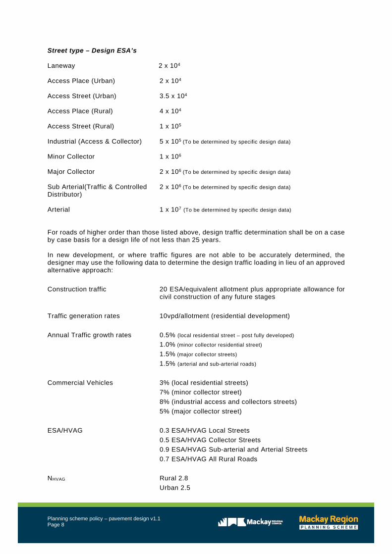
Street type – Design ESA’s Laneway 2 x 10⁴ Access Place (Urban) 2 x 10⁴ Access Street (Urban) 3.5 x 10⁴ Access Place (Rural) 4 x 10⁴ Access Street (Rural) 1 x 10⁵
Industrial (Access & Collector) 5 x 10⁵ (To be determined by specific design data) Minor Collector 1 x 10⁶ Major Collector 2 x 10⁶ (To be determined by specific design data) Sub Arterial(Traffic & Controlled 2 x 10⁶ (To be determined by specific design data) Distributor) Arterial 1 x 10⁷ (To be determined by specific design data) For roads of higher order than those listed above, design traffic determination shall be on a case by case basis for a design life of not less than 25 years. In new development, or where traffic figures are not able to be accurately determined, the designer may use the following data to determine the design traffic loading in lieu of an approved alternative approach: Construction traffic 20 ESA/equivalent allotment plus appropriate allowance for
civil construction of any future stages Traffic generation rates 10vpd/allotment (residential development) Annual Traffic growth rates 0.5% (local residential street – post fully developed) 1.0% (minor collector residential street)
1.5% (major collector streets)
1.5% (arterial and sub-arterial roads)
Commercial Vehicles 3% (local residential streets) 7% (minor collector street) 8% (industrial access and collectors streets) 5% (major collector street) ESA/HVAG 0.3 ESA/HVAG Local Streets 0.5 ESA/HVAG Collector Streets 0.9 ESA/HVAG Sub-arterial and Arterial Streets 0.7 ESA/HVAG All Rural Roads NHVAG Rural 2.8 Urban 2.5

Planning scheme policy – pavement design v1.1 Page 9
3.2 Subgrade evaluation Except where a mechanistic design approach is employed using Austroads – Guide to Pavement Technology Part 2: Pavement Structural Design, the measure of subgrade support shall be the soaked four day California Bearing Ratio (CBR). Where a mechanistic design approach using linear elastic theory is employed for flexible pavements, the measure of subgrade support shall be in terms of the elastic parameters (modulus, Poisson’s ratio). The following factors must be considered in determining the design strength/stiffness of the subgrade: (a) sequence of earthworks construction; (b) the compaction moisture content and field density specified for construction; (c) moisture changes during service life; (d) subgrade variability; and (e) the presence or otherwise of weak layers below the design subgrade level. The subgrade design CBR adopted for the pavement design must consider the effect of moisture changes in the pavement and subgrade during the service life. Accordingly consideration must be given to the provision of subsurface drainage in the estimation of equilibrium in-situ CBRs, and hence in the design of the pavement structure. Warrants for the provision of subsurface drainage are given in Planning scheme policy – subsurface drainage design. If subsurface drainage is not to be provided, then the Design CBR adopted must allow for a greater variability in subgrade moisture content during the service life of the pavement, and hence Design Moisture Content above the Optimum Moisture Content. The calculation of the Design CBR shall be based on soaked conditions. All design assumptions and engineering judgments used to determine the Design CBR are to be included in the pavement design report. (a) Soaked conditions are to be adopted for the calculation of Design CBR and shall be based on a
minimum of 3 x 4-day soaked CBR laboratory samples for each subgrade area compacted to 100 percent of standard maximum dry density
(b) The maximum spacing of test sites for field inspection pits is to be:
(i) 100 metres for urban projects, minimum of two tests; and (ii) 250 metres for rural projects, minimum of three tests;
(c) Once each subgrade area has been classified according to its particular soil type and drainage
assessed, the Design CBR for each subgrade area is computed by using the appropriate formulae as follows: (i) Design CBR = Least of individual CBRs, for less than five results (ii) Design CBR = 10th percentile of all individual CBRs, for five or more results = C – 1.3S (iii) Where C is the mean of all individual CBR tests, and S is the standard deviation of all values
Where the Design CBR, as determined above, is calculated to be less than 3, then the design engineer is to: (a) Design and detail, by an industry recognised method acceptable to Council, the
improvement measures required to improve the insitu sub-grade to CBR 3; and (b) Design the pavement above the improved subgrade.

Planning scheme policy – pavement design v1.1 Page 10
Where practicable, the design obtained by adopting the CBR from laboratory testing should be confirmed by testing existing road pavements near to the job site under equivalent conditions and displaying similar sub grades. The pavement design report shall be prepared and certified by the Designer or a sub-consultant who is a suitably qualified and experienced RPEQ and include a summary of all laboratory and field test results and assumptions and / or calculations made in the assessment of subgrade support.
3.3 Environment The environmental factors that significantly affect pavement performance are moisture and temperature. Both of these factors must be considered at the design stage of the pavement. Reference should be made to the following documents:
AustRoads – Guide to Pavement Technology Part 8: Pavement Construction AustRoads – Guide to Pavement Technology Part 10: Sub-Surface Drainage
. The following factors relating to moisture environment must be considered in determining the design subgrade strength/stiffness and in the choice of pavement and surfacing materials: (a) rainfall / evaporation pattern; (b) permeability of wearing surface; (c) depth of water table and salinity problems; (d) relative permeability of pavement layers; (e) whether shoulders are sealed or not; and (f) pavement type (boxed or full width). The effect of changes in moisture content on the strength/stiffness of the subgrade shall be taken into account by evaluating the design subgrade strength parameters (i.e. CBR of modulus) at the equilibrium moisture content likely to occur during the design life, i.e. the Design Moisture Content. The provision of subsurface drainage may, under certain circumstances, allow a lower Design Moisture Content, and hence generally higher Design CBR. The effect of changes in temperature environment must be considered in the design of pavements with asphalt wearing surfaces, particularly if traffic loading occurs at night when temperatures are low, thus causing a potential reduction in the fatigue life of thin asphalt surfacing. The effect of changes in temperature environment should also be considered for bound or concrete layers. The pavement design report shall include all considerations for environmental factors, and any assumptions made that would reduce or increase design subgrade strength, or affect the choice of pavement and surfacing materials.
3.4 Pavement and surfacing materials The design will take into account the CBR of the Subgrade material when designing the pavement. In doing so the Designer shall consider what construction techniques and subsequent plant and equipment

Planning scheme policy – pavement design v1.1 Page 11
are likely to be adopted. The adopted Subgrade CBR and traffic loading utilised to obtain the pavement design are to be included as a notation on the plans and within the specifications. Nominal pavement designs are not to be used. The Design is to explore and document several options to minimise the use of virginal materials, for example, but not limited to:- • Unbound pavements • Modified/stabilised pavement layers • Lime stabilisation of Subgrade • Tensar grid • Reuse of existing pavement materials • Insitu stabilisation of existing pavement materials • Foam Bitumen stabilisation • Bitumen Treated Base (BTB) • Utilising existing quarries / pit gravels The Pavement Designer is to account for the availability of local quarries to supply approved pavement gravels to reduce supply/cartage costs. The extent of the project that may require Subgrade treatment, and the type of treatment required, are to be considered by the Designer. The Designer shall document all relevant design assumptions for information of the roadwork contractor. An allowance for Subgrade treatment is to be made in the design estimate as a standard, or provisional, item in the case of Council designs. Pavement materials can be classified into essentially four categories according to their fundamental behaviour under the effects of applied loadings: (a) unbound granular materials, including modified granular materials (b) bound (cemented) granular materials (c) asphaltic concrete (d) cement concrete Surfacing materials can be classified into essentially three categories or types:
(i) sprayed bituminous seals (chip seals) (ii) asphaltic concrete and bituminous micro surfacing (cold overlay) (iii) cement concrete
All material types shall satisfy the requirements of the relevant construction specification applying to the project. The use of sprayed bituminous seal (chip seal) is not an acceptable wearing surface on any urban street, regardless of road hierarchy level classification, unless otherwise approved by Council.
4 Pavement thickness design 4.1 Pavement structure – general Unless otherwise approved, all pavement materials shall be supplied from commercial quarries, or recycled materials which meet required specifications, where the material is to comply with the requirements of the Department of Main Roads Standard Specification MRTS05 Unbound Pavements.

Planning scheme policy – pavement design v1.1 Page 12
Current test results may be required to be submitted to Council to support the quality of material that is proposed to be used. Where pavement materials from new quarries or gravel pits are proposed for use, current test results for CBR, Atterberg limits and material grading (as a minimum) shall be provided for Council approval within fourteen (14) days of the design submission. Notwithstanding subgrade testing and subsequent pavement thickness design, the thickness of sub base and base layers shall not be less than that set out in Tables 4.1.A and 4.1.B below. Table 4.1.A – Sub-base and base layer pavement thickness – flexible pavement
Design Traffic (DESA’s)
Pavement Layer (mm) Sub-base Base
<1 x 10⁵ < 2x 10⁵ 125 125 >2 x 10⁵ 150 150
Table 4.1.B – Sub-base and base layer pavement thickness – rigid pavement
Design Traffic (DESA’s)
Pavement Layer (mm) Sub-base Base
All values 100 150 The sub base layer shall extend a minimum of 300mm behind the back of any kerbing and/or channel. The base and surfacing shall extend to the face of any kerbing and/or channel. Where the top surface of the sub base layer is below the level of the underside of the kerbing and/or channel, the base layer shall also extend a minimum of 300mm behind the rear face of the kerbing and/or channel. For un-kerbed roads, the sub base and base layers shall extend at least to the nominated width of shoulder and shall provide for free drainage of both layers. The Designer or pavement design engineer shall make specific allowance for traffic load concentrations within carpark areas (e.g. entrances/exists). The minimum pavement thickness for carparks is to be 150mm. The Designer or pavement design engineer shall make provision for pavement layer drainage on the assumption that during the service life of the pavement ingress of water will occur. Pavement design systems either mechanistic or empirical can be utilised in accordance with recommendations contained in Austroads – Guide to Pavement Technology Part 2: Pavement Structural Design. Council’s preferred system of design utilises computer software such as CIRCLY to determine pavement structures. In such instances all electronic files for the design output are to be provided to Council as evidence of the design. In general terms all material properties including Poisson’s ratios and vertical modulus used for the various pavement options shall be extracted from the following reference documents unless alternatives can be supported by independent test data:
• Austroads – Guide to Pavement Technology Part 2:Pavement Structural Design • Department of Transport and Main Roads, Pavement Design Supplement • Department of Transport and Main Roads Specifications(MRTS) • Department of Transport and Main Roads, Guideline - Structural design procedure of
pavements on lime stabilised subgrades guideline Council provides the following CIRCLY6 and CIRCLY7 materials databases as the basis of the thickness designs.

Planning scheme policy – pavement design v1.1 Page 13
https://www.mackay.qld.gov.au/business/planning_and_development/design_and_construction_requirements
Should the Designer utilise alternative materials criteria Council would require submission of justification for these criteria to be used including test data.
Pavement designs shall match existing pavement widths, where works are required on, or to extend an existing street or road and the existing pavement width is greater than specified.
4.2 Unbound granular flexible pavements (bituminous surface) The Designer shall refer to the relevant Reference document listed below, and adhere to the design approach detailed in the document, for the design of sealed flexible pavements: • <106 EAS's AustRoads - Guide to Pavement Technology - Part 2: Pavement Structural Design Section 12. • >106 EAS's AustRoads - Guide to Pavement Technology - Part 2: Pavement Structural Design Section 2 - 11. The design of the pavements is based on the traffic volumes (measured in ESA’s) over the design life of the pavement.
• Unbound granular flexible pavements designed in accordance with • Austroads – Guide to Pavement Technology Part 2:Pavement Structural Design shall use
the 95% confidence limit curves for urban projects and 90% confidence limits for rural projects.
Temporary turnarounds (eg. at development stage boundaries) are to be compacted and sealed gravel, minimum 150mm deep and contained within a road reserve or appropriate easement.
4.3 Flexible pavements containing bound layers (bituminous surfaced)
Cement stabilised base or sub-base courses are not preferred for new road construction Flexible pavements containing one or more bound layers including cement stabilised layers or asphaltic concrete layers other than thin asphalt surfacing, shall be designed in accordance with:
• Austroads – Guide to Pavement Technology Part 2: Pavement Structural Design • AustRoads – Pavement design for light traffic – a supplement to AustRoads pavement
design.
4.4 Rigid pavements Rigid (concrete) pavements shall be designed in accordance with Austroads – Guide to Pavement Technology Part 2:Pavement Structural Design.

Planning scheme policy – pavement design v1.1 Page 14
5 Surfacing design 5.1 Choice of surface types Except where the pavement is designed for concrete surfacing on urban access streets and places, the wearing surface shall be a bituminous wearing surface as indicated on the standard road hierarchy cross-sections as follows: (a) all street and roads (urban areas) – primerseal, plus asphalt; or (b) all streets and roads (rural areas):
(i) prime plus two coat chip seal; or (ii) primer seal, plus asphalt; or (iii) primer seal plus final seal and (iv) primerseal plus asphalt on all heavy vehicle or agricultural equipment rotation
locations at intersections or property access locations. At all intersections and cul-de-sac turning circles on streets the design engineer shall take into account the vehicle braking and turning movements in the design and specification of the bituminous materials to be adopted. Consideration must be given in the selection of surfacing grade and type to impacts of heavy vehicle generated shear stress on the design life of the surfacing type Council may approve variations to these requirements in special circumstances. However, to obtain the variation approval, the Designer must present a written developed case outlining the benefits of the modification including consideration of capital and maintenance impacts to Council of the proposed change. Council reserves the right to refuse the request.
5.2 Sprayed bituminous seals (chip seals) The design of sprayed bituminous (chip) seals, including primer seals, shall be in accordance with AustRoads – Guide to Pavement Technology Part 4K: Seals. All aggregate used shall be precoated. 7mm primer seals shall be indicated on the Drawings below all asphalt surfacing. Where a 7mm primer seal is inappropriate, a 10mm primer seal shall be used in lieu. Two-coat chip seals shall be double-double seals comprising a minimum of two coats binder and two coats of aggregate. The preferred seal types are: (a) 1st coat – 1mm; and (b) 2nd coat – 10mm. Single coat chip seals shall only be approved if asphaltic concrete is to be applied as the finished surface at a nominated later date.
5.3 Bituminous micro surfacing (cold overlay) Any bituminous micro surfacing, also referred to as ‘cold overlay’, shall be designed to provide a nominal compacted thickness of not less than 8mm.

Planning scheme policy – pavement design v1.1 Page 15
5.4 Asphaltic concrete In general terms the minimum layer thickness to be applied are as described on the road hierarchy type cross sections but are as follows:
• AC10M for up to 35mm • AC14M greater than 35mm
In all road hierarchy’s of major collectors and above Asphaltic surfacing shall utilise a PMB binder of a suitable grade to the specific situation, loading and shear stresses assessed. Similar assessments are to be considered for all intersections including those of low order streets and roads which should be assessed for impacts of traffic and particularly heavy vehicle shear stresses which may generate the need to utilise PMB binders. On urban and rural roads the asphalt mix design shall be in accordance with AustRoads – Guide to Pavement Technology Part 4B: Asphalt & MRTS30 Asphalt Pavements. The Designer shall provide a minimum asphaltic compacted layer thickness as shown on the appropriate Council Standard Cross-section Drawing and not less than 50mm on intersections involving a collector street, or higher road hierarchy classification streets/roads. A 7mm primer seal shall be indicated on the Drawings below all asphalt surfacing. Where a 7mm primer seal is considered inappropriate, a 10mm primer seal shall be indicated in lieu.
6 Documentation – design criteria and calculations All drawings and documentation to be submitted to Council shall conform to the requirements of Council’s Drawings and documentation guidelines. A copy of these guidelines will be made available on request. The drawings shall clearly indicate the structure, material types and layer thicknesses of the proposed pavement and wearing surface. All considerations, assumptions, subgrade test results, reference material and calculations shall be submitted with the pavement and wearing surface course design. Failure to comply with Council’s Drawings and documentation guidelines may result in the drawing and/or documentation being returned to the Designer without consideration by Council. Documentation submitted shall include the Pavement Design report and provision of all electronic files from relevant pavement design software utilised where applicable.
Related Documents


