PLANNING & INSTALLATION Isocolor Structura Isocolor Structura Balkonplatten Isocolor Natura Isocolor Pigmenta Eternit-Tergo Eternit-Pikto Eternit-Naxo Eternit-Linar CLADDING WITH FIBRE CEMENT ROOFING CLADDING INTERIOR Edition 2007

Welcome message from author
This document is posted to help you gain knowledge. Please leave a comment to let me know what you think about it! Share it to your friends and learn new things together.
Transcript
PLA
NN
ING
&IN
STA
LLA
TIO
N
Isocolor StructuraIsocolor Structura BalkonplattenIsocolor NaturaIsocolor Pigmenta
Eternit-TergoEternit-PiktoEternit-NaxoEternit-Linar
C L A D D I N G W I T H F I B R E C E M E N T
R O O F I N G C L A D D I N G I N T E R I O R
Editi
on 2
007

2
1 2 3
4 5 6
7 8 9
10 11 12
Service-Line +49 30 34 85 [email protected]
1. Shopping Mall “Schwabengalerie”, Stuttgart,GermanyDesign: Léon Wohlhage Wernik Architekten, Berlin,Germany
2. Leisure Centre, Belfast, Northern IrelandDesign: Kennedy, Fitzgerald & Ass., Befast,Northern Ireland
3. Stadion Francois André, La Baule, FranceDesign: Esteve & Boucheton, Nates, France
4. Community Centre, Oosterhout, NetherlandsDesign: Jeanne Dekkers Architecture, Delft,Netherlands
5. Airport Houari Boumediene, Algiers, AlgeriaDesign: Airport de Paris
6. Metro Station, Santiago de Chile, ChileDesign: Cade-Idepe, Mario Correa and Sandra Zamorano, Chile
7. Airport, Dresden, GermanyDesign: Planungsgruppe Blees & Kampmann,Munich, Germany
8. Porsche Service Centre, Stuttgart, GermanyDesign: Dierig Architekten, Ravensburg, Germany
9. Allianz Headquarter, Munich, GermanyDesign: HPP Hentrich-Petschnigg & Partners,Cologne, Germany
10. Hotel Iris, Granollers, SpainDesign: Francesc Vargas, Granollers
11. Eternit Headquarter, Heidelberg, GermanyDesign: Astrid Bornheim, Berlin, Germany
12. Eternit Headquarter, Heidelberg, GermanyDesign: Astrid Bornheim, Berlin, Germany
Front cover:Property: Youth centre, Berlin-SteglitzDesign: Eckert Negwer Suselbeek Architekten, BerlinProduct: Eternit Natura 8 und 12 mm riveted onto analuminium subconstruction
For further information to these projects, see brochure“Eternit International”

3
Technical state of the art 2006All notes, technical and graphic information correspond tothe current technical state of the art and to our experiencebased on this. The installations described are examples anddo not take into consideration the particular conditions inevery individual case. Details and suitability of the materialsfor the intended construction purposes must be checked bythe client in any case. Eternit AG accepts no liability. This alsoincludes misprints and subsequent changes to technicaldetails.
For over a century, architects have beendesigning innovative architecture withfibre cement cladding produced by Eternit.Many of these buildings have made theirmark in architectural history; others havebeen awarded major architectural prizes.New developments by Eternit provideexciting opportunities to continue this finearchitectural tradition.Non-combustible fibre cement panels byEternit (building materials class A2) aresituable for buildings of every type andheight and for balcony panels. They areavailable throughcoloured with mattcolour varnish (Natura) or with a colourcoating (Structura). A wide range of fixingsystems with edging profiles and stainlesssteel components (Eternit-Naxo) are alsoavailable. The panels can also be structu-rally bonded, or mounted “secretly” usingundercut anchors (Eternit-Tergo).This brochure will provide you with ideasfor the design and a practical guide for theconstruction of your building. Be it an offi-ce building, laboratory, school, kindergar-ten or residential building: the projectspresented are aesthetically, constructivelyand economically impressive. The ventila-ted façade with fibre cement panels hasalso proven to be a reliable system in
building renovation with favourable physi-cal properties and excellent design quali-ties.A selection of projects is presented usingdetailed façade sections and numerousconstruction details.In addition, qualified cladding experts pro-vide individual advice on your specific pro-perty – by telephone or on site. Particularlyin matters concerning detailed planning,cost estimates and optimising economicefficiency, we will assist you in everyphase of the construction process. Use ourknow-how for forward-looking claddingsystems.
Eternit AGSales Export
F a ç a d e s a n d B a l c o n i e s w i t h E t e r n i t
I n t r o d u c t i o n
Every cladding panelproduced by Eternit istested and certified asbeing of environment-ally compatible and healthy building mate-rial.
German association of BuildingMaterials and Components for Ventilated Rainscreen
Claddingwww.fvhf.de
We are a member of the
Plan
ning
& In
stal
latio
n 20
07 ·
Ete
rnit
Faça
des
with
Fib
re C
emen
t
Iso
co
lor
®D
ur
ch
ge
fär
bt
4
Ca
se
Stu
dy
Planning & Installation 2007 · Eternit Façades with Fibre Cement

C o n t e n t
5
P r o d u c t R a n g e
A p p e n d i x
Tergo / Naxo façade systems 50
Weatherboarding 56
Structural bonding 59
Structura 61
Natura 62
Natura ivory-color 63
Accessories 64
Order form for panels / drilling 66
Construction principle of ventilated cladding 68
Service 69
Colour range 71
Fax info 73
Note:This pictogram in the text indicatesfurther information.
Terg
oNa
xoW
eath
erbo
ardi
ngRe
nova
tion
Desi
gn T
hem
esPl
anni
ngIn
form
atio
nLa
ying
Prod
uct
Info
rmat
ion
Prod
uct R
ange
F a ç a d e s w i t h E t e r n i t Façades panels 6
Façades systems and aspects of design 7
E x a m p l e s i n U s e
P l a n n i n g I n f o r m a t i o n
Structura 8
Natura 10
Tergo / Naxo façade systems 12
Weatherboarding 16
Renovation of residential high rise buildings 18
Product descriptions / applications 20Technical data / calculations / regulations 22Requirements / certification of structural stability 24Fire protection soundproofing and condensation 26Thermal insulation and weatherproofing 27On-site work 28
Edge finishing after sawing 29Installing on a wooden subconstruction 31Installing on an aluminium subconstruction 37Standard solutions 46
Photo left:RS + Yellow Möbel, MünsterDesign: Bolles + Wilson, MünsterPelicolor Orange P 701Façade + view of ceiling from belowPhoto: Christian Richters, Münster
Imprint:Eternit AG · Sales exportEditors: Jan R. Krause, Silvia Lutz, Uwe HammannRegistered office:Eternit AG · Im Breitspiel 20 · D-69126 Heidelberg · GermanyCompany register: Heidelberg HRB 7456
6
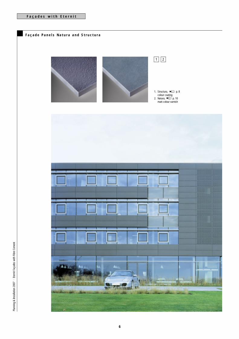
F a ç a d e P a n e l s N a t u r a a n d S t r u c t u r a
1 2
F a ç a d e s w i t h E t e r n i t
1. Structura, p. 8colour coating
2. Natura, p. 10matt colour varnish
Plan
ning
& In
stal
latio
n 20
07 ·
Ete
rnit
Faça
des
with
Fib
re C
emen
t
7
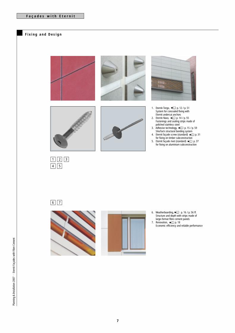
F i x i n g a n d D e s i g n
1 2
4
3
5
6 7
F a ç a d e s w i t h E t e r n i t
1. Eternit-Tergo, p. 12 / p. 51System for concealed fixing withEternit undercut anchors
2. Eternit-Naxo, p. 14 / p. 55Fastenings and sealing strips made ofpolished stainless steel
3. Adhesive technology, p. 15 / p. 59SikaTack structural bonding system
4. Eternit façade screw (standard) p. 31for fixing on timber subconstruction
5. Eternit façade rivet (standard) p. 37for fixing on aluminium subconstruction
6. Weatherboarding, p. 16 / p. 56 ff.Structure and depth with strips made oflarge-format fibre cement panels
7. Renovation, p. 18Economic efficiency and reliable performance
Plan
ning
& In
stal
latio
n 20
07 ·
Ete
rnit
Faça
des
with
Fib
re C
emen
t
8
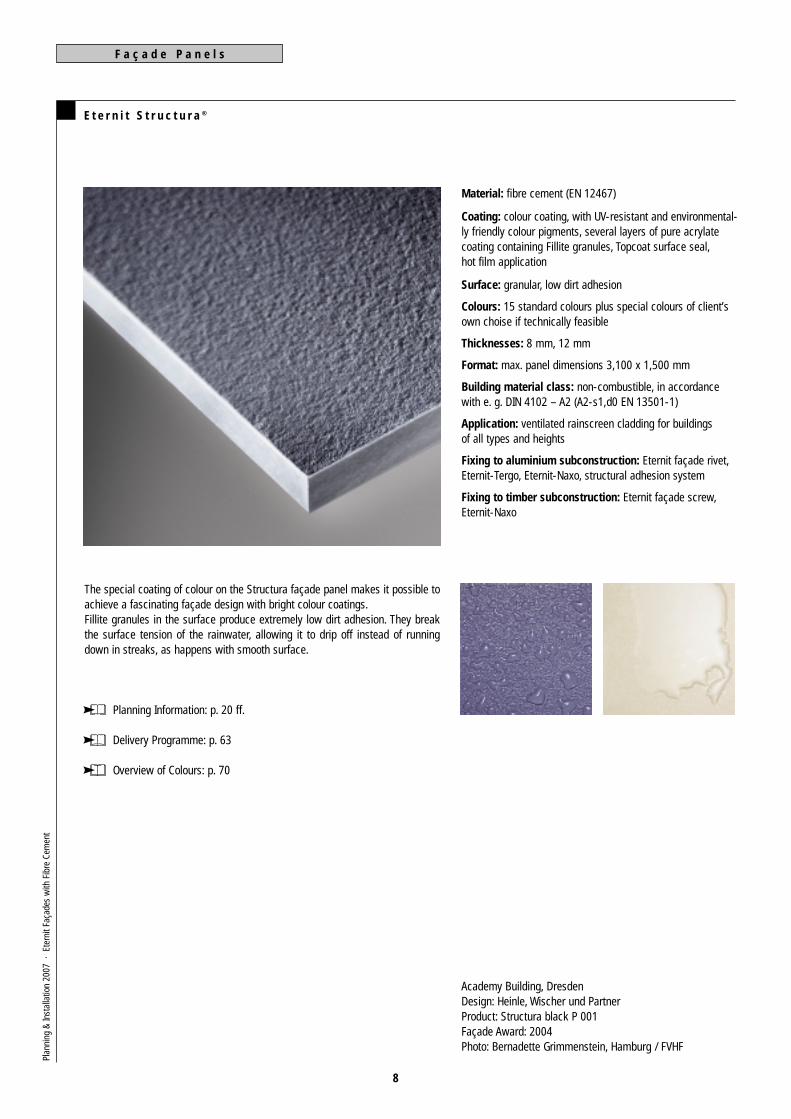
E t e r n i t S t r u c t u r a ®
Material: fibre cement (EN 12467)
Coating: colour coating, with UV-resistant and environmental-ly friendly colour pigments, several layers of pure acrylatecoating containing Fillite granules, Topcoat surface seal,hot film application
Surface: granular, low dirt adhesion
Colours: 15 standard colours plus special colours of client’sown choise if technically feasible
Thicknesses: 8 mm, 12 mm
Format: max. panel dimensions 3,100 x 1,500 mm
Building material class: non-combustible, in accordancewith e. g. DIN 4102 – A2 (A2-s1,d0 EN 13501-1)
Application: ventilated rainscreen cladding for buildingsof all types and heights
Fixing to aluminium subconstruction: Eternit façade rivet,Eternit-Tergo, Eternit-Naxo, structural adhesion system
Fixing to timber subconstruction: Eternit façade screw,Eternit-Naxo
The special coating of colour on the Structura façade panel makes it possible toachieve a fascinating façade design with bright colour coatings.Fillite granules in the surface produce extremely low dirt adhesion. They breakthe surface tension of the rainwater, allowing it to drip off instead of runningdown in streaks, as happens with smooth surface.
Planning Information: p. 20 ff.
Delivery Programme: p. 63
Overview of Colours: p. 70
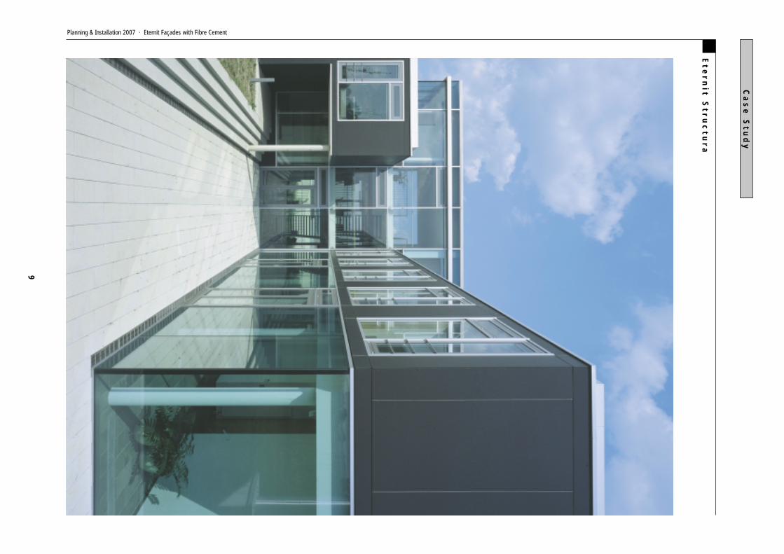
Academy Building, DresdenDesign: Heinle, Wischer und PartnerProduct: Structura black P 001Façade Award: 2004Photo: Bernadette Grimmenstein, Hamburg / FVHF
F a ç a d e P a n e l sPl
anni
ng &
Inst
alla
tion
2007
· E
tern
it Fa
çade
s w
ith F
ibre
Cem
ent
Ete
rn
it Str
uc
tur
a
9
Ca
se
Stu
dy
Planning & Installation 2007 · Eternit Façades with Fibre Cement

10
E t e r n i t N a t u r a ( i n c l u d i n g f o r m e r t h r o u g h c o l o u r e d p r o g r a m )
Material: throughcoloured fibre cement (EN 12467)
Coating: matt varnish on grey or anthracite throughcolouredboards, with UV-resistant and environmentally friendly colourpigments, several layers of pure acrylate coating, hot filmapplication
Surface: smooth with the texture of the fibre cement showing through
Colours: 42 standard colours
Thicknesses: 8 mm, 12 mm
Format: max. effective panel dimensions 3,100 x 1,250 mm.The edges must be impregnated using Luko edge sealing
Building material class: non-combustible, in accordancewith e. g. DIN 4102 – A2 (A2-s1,d0 EN 13501-1)
Application: ventilated rainscreen cladding for buildings of alltypes and heights, and interior fit-out
Fixing to aluminium subconstruction: Eternit façade rivet,Eternit-Tergo, structural adhesion system
Fixing to timber subconstruction: Eternit façade screw,Eternit-Naxo
The coloured varnish of the Natura panels allows the texture of the fibre cementto show through. Irregularities, differences in shade and traces of the manufac-turing process are to be expected.
Planning Information: p. 20
Delivery Programme: p. 64, 66
Colour Range: p. 72
School complex, StettenDesign: dk Architekten, StuttgartAxel Dorner, Elmar KönigProduct: Natura Photo: Zooey Braun
F a ç a d e P a n e l sPl
anni
ng &
Inst
alla
tion
2007
· E
tern
it Fa
çade
s w
ith F
ibre
Cem
ent
Ete
rn
it Na
tur
a
11
Ca
se
Stu
dy
Planning & Installation 2007 · Eternit Façades with Fibre Cement

12
E t e r n i t - Te r g o ® D e s i g n S y s t e m s
The splayed Eternit undercutanchor locks snugly into the pre-drilled blind hole on the back ofthe 12 mm thick fibre cementpanel to ensure that forces aretransferred uniformly.
Eternit-Tergo is a façade system for secret fixing to subcon-structions made of aluminium. In addition to high-quality, tai-lor-made and cladding panels with undercut fixing holes onthe back, the system also includes special Eternit undercutanchors, along with matching screws and washers.Building regulations for Eternit-Tergo allow free scope fordesigns using cladding panels up to the full sizes of 3,100 x1,500 mm for Structura and 3,100 x 1,250 mm for Natura.The 12 mm thick panels are attached to an aluminium sub-construction by concealed fixings in the form of panels han-gers or panel rails.
The Bavarian Environment Agency in Augsburg was clad inNatura panels with a red finish, fixed with condealedfastenings using the Eternit-Tergo façade system.Design: Kaup, Scholz, Jesse + Partner, Munich.
Planning Information: p. 51
F a ç a d e s y s t e m s
Terg
o
Plan
ning
& In
stal
latio
n 20
07 ·
Ete
rnit
Faça
des
with
Fib
re C
emen
t

Ete
rn
it-T
er
go
®
13
Ca
se
Stu
dy
Tergo
Planning & Installation 2007 · Eternit Façades with Fibre Cement
14
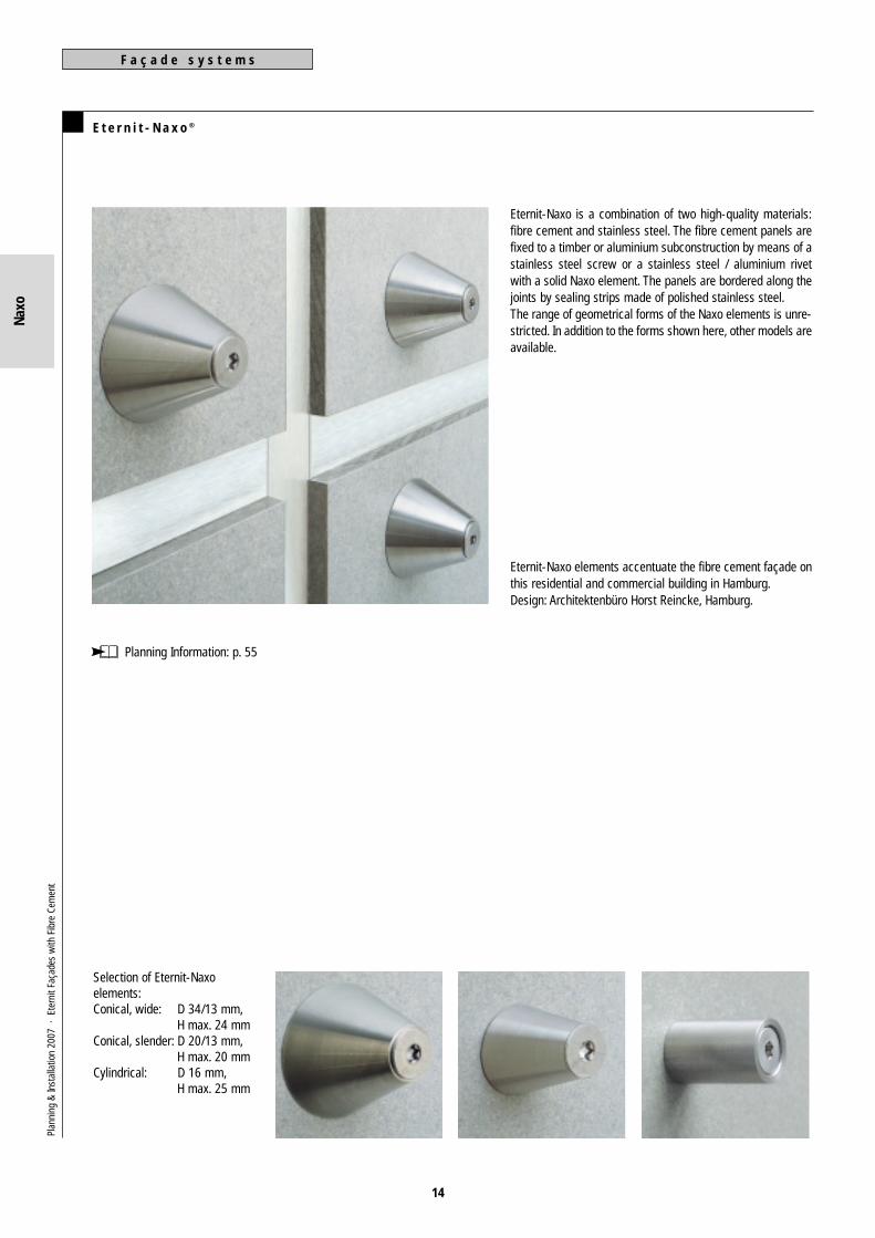
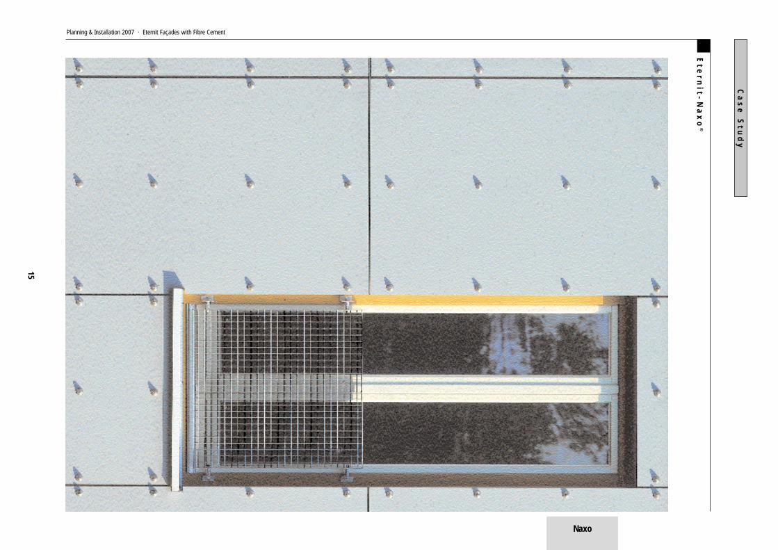
E t e r n i t - N a x o ®
Selection of Eternit-Naxo elements:Conical, wide: D 34/13 mm,
H max. 24 mmConical, slender: D 20/13 mm,
H max. 20 mmCylindrical: D 16 mm,
H max. 25 mm
Eternit-Naxo is a combination of two high-quality materials:fibre cement and stainless steel. The fibre cement panels arefixed to a timber or aluminium subconstruction by means of astainless steel screw or a stainless steel / aluminium rivetwith a solid Naxo element. The panels are bordered along thejoints by sealing strips made of polished stainless steel.The range of geometrical forms of the Naxo elements is unre-stricted. In addition to the forms shown here, other models areavailable.
Eternit-Naxo elements accentuate the fibre cement façade onthis residential and commercial building in Hamburg.Design: Architektenbüro Horst Reincke, Hamburg.
Planning Information: p. 55
F a ç a d e s y s t e m sPl
anni
ng &
Inst
alla
tion
2007
· E
tern
it Fa
çade
s w
ith F
ibre
Cem
ent
Naxo
Ete
rn
it-N
ax
o®
15
Ca
se
Stu
dy
Planning & Installation 2007 · Eternit Façades with Fibre Cement
Naxo

16
W e a t h e r b o a r d i n g
Weatherboarding can be moun-ted on an aluminium or timbersubconstruction using visible orconcealed fixing. The modellingof the façade is enhanced by in-creased recessing to create astronger shadow line.
Concealed
fixing
Concealed
fixing with
shadow gap
Visible
fixing
Weatherboarding can lend optical depth and structure to afaçade. It is laid out on the basis of panel dimensions, whichmay be individually selected. Weatherboarding is distinctivethanks to its extraordinary diversity. Numerous options areavailable. Entirely new effects can be achieved by makingminor modifications.The result of laying simple horizontal weatherboarding on analuminium or timber subconstruction is reminiscent of the tra-ditional forms of rural buildings. Larger panels emphasise theabstract character of a building. Brackets can be used toincrease the recess between boards and create a strongershadow line.
On this residential and commercial block in Oranienburg,designed by architects Gruber + Popp, the weatherboarding ofwhite Natura façade panels lends the northern façade anunexpectedly three-dimensional appearance, which is furtheraccentuated by the deepset windows. The panels are fixedusing concealed fastenings and arranged staggered, in cour-ses. This produces a refined play of shadows, which is furtherenhanced by joints lined in cobalt blue.Design: Gruber + Popp, Berlin.
Planning Information: p. 56 ff
A s p e c t s o f D e s i g nPl
anni
ng &
Inst
alla
tion
2007
· E
tern
it Fa
çade
s w
ith F
ibre
Cem
ent
Wea
ther
boar
ding

We
ath
er
bo
ar
din
g
17
Ca
se
Stu
dy
Planning & Installation 2007 · Eternit Façades with Fibre Cement
Weatherboarding

18
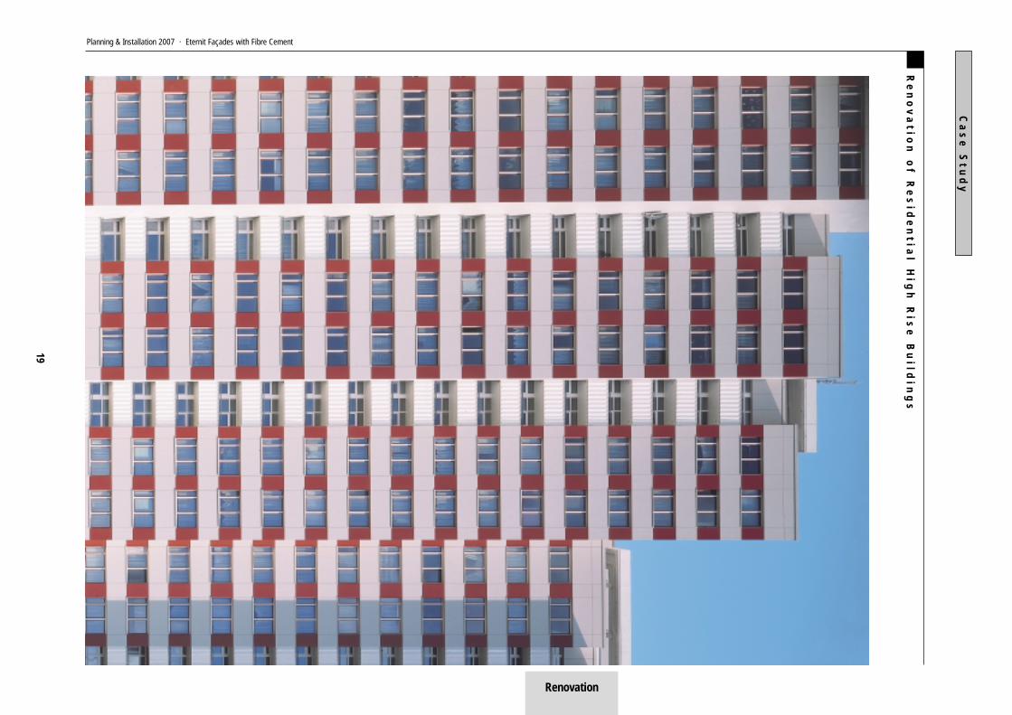
R e n o v a t i o n o f R e s i d e n t i a l H i g h R i s e B u i l d i n g s
Exemplary façade renovation:Residential tower blocks, Fischer-insel, Berlin.Mendelssohnviertel housingestate, Berlin.
The main objective of façade renovation is to preserve thefabric of the building and to improve the quality of housing.Ventilated rainscreen cladding meets a high standard of faça-de design and offers a sustainable solution for achievingimproved heat insulation along with reliable physical perfor-mance. The aluminium subconstruction allows structural tole-rance to be optimised.
In the case of this renovated residential building at Platz derVereinten Nationen in Berlin, coloured panels have been usedto connect pairs of windows and give the façade a bandedappearance. The balconies and the areas between the win-dow strips are, like the side walls, clad in an pale colour. Themassing of the six staggered sections of the building is accen-tuated by the vivid colour and texture of the Structura claddingpanels, while the stripes bring them together as a unifiedwhole.
Colour scheme: Hans Albrecht Schilling, Bremen.
A s p e c t s o f D e s i g nPl
anni
ng &
Inst
alla
tion
2007
· E
tern
it Fa
çade
s w
ith F
ibre
Cem
ent
Reno
vatio
n
Re
no
va
tion
of R
es
ide
ntia
l Hig
h R
ise
Bu
ildin
gs
19
Ca
se
Stu
dy
Planning & Installation 2007 · Eternit Façades with Fibre Cement
Renovation
P r o d u c t D e s c r i p t i o nP l a n n i n g I n f o r m a t i o n
20
F i b r e C e m e n t
Fibre cement is a modern reinforced materialmade of natural and environmentally friendlyraw materials. The sum of this material’s posi-tive characteristics fulfils today’s high expec-tations for construction and design. This tech-nology can now look back on more than twen-tyfive years of development, observation andexperience in laboratory and acceleratedtests, as well as actual long-term on-site.Since 1980 many million square metres offibre cement products have been installed onroofs and façades, withstanding extreme cli-matic conditions.Large size fibre cement panels for backventi-lated rainscreen façades have proved to behighly successful in everyday use. They con-sist of a non-combustible, dense material,fibre-reinforced hydrated cement, which isdimensionally stable and weatherproof in its
hardened state. Of the raw material used infibre cement, the greater part consists of thebonding agent portland cement, which is pro-duced by burning limestone and clay marl. Inorder to optimise this product’s properties,additional materials are added, e. g. poweredlime.Synthetic organic fibres made from polyvinylalcohol are used as reinforcing fibres. Thesefibres are similar to those used in the textileindustry to produce outerwear, protectivefabrics, fleece, and for medical stitchingthread. Of great importance is their physiologi-cal safety. During the production of fibrecement, so-called process fibres act as filterfibres. These consist mainly of cellulose fibressimilar to those used in the paper industry. Airis also present in the form of microscopicallysized pores. Owing to the presence of this
micropore-system, a frost-resistant, moisture-regulating, breathable and yet impermeablematerial is created.Products made of fibre cement react in a com-pletely neutral fashion to electromagneticwaves and radiation, so that radio waves,infrared facilities, personal paging systemsand radar waves are not adversely affected.The industrially applied multiple hot-film sur-face guarantees cladding panels with a consi-stently high standard of quality. They are non-fading and UV-stable. A sealing coat of equal-ly high physical quality is applied to the rear ofeach panel. Every cladding panel produced byEternit AG is tested and certified as an envi-ronmentally compatible and healthy buildingmaterial.
M a t e r i a l P r o p e r t i e s
Structura and NaturaColor-coated façade panels made of pressed,hardened fibre cement have an ideal staticprofile and are
– non-combustible A2-s1,d0 (EN 13501-1)– weatherproof and frost-resistant– impermeable– rot-proof
– impact-resistant– shockproof and UV-stable.
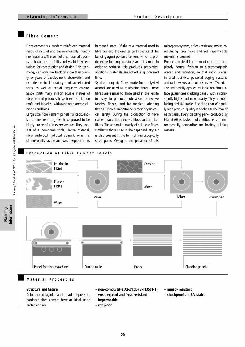
P r o d u c t i o n o f F i b r e C e m e n t P a n e l s
Plan
ning
&In
stal
latio
n 20
07 ·
Ete
rnit
Faça
des
with
Fib
re C
emen
t
Plan
ning
Info
rmat
ion
ReinforcingFibres
ProcessFibres
Water
Panel-forming maschine Cutting table Press Cladding panels
Water
Mixer Stirring Vat
Cement
Mixer

A p p l i c a t i o n sP l a n n i n g I n f o r m a t i o n
21
A p p l i c a t i o n s
Large size fibre cement panels are chieflyused for:– External cladding of buildings, ventilated;
in accordance with e. g. DIN 18516-1
– infilling with post-and-rail construction– weatherboarding– exterior cladding of prefabricated com-
posite elements (sandwich elements)
– cornice flashing– cladding of window reveals– cladding of window and door headers– lining of interior walls– verges and eaves fascia– soffit boards– balcony fasciasPl
anni
ng &
Inst
alla
tion
2007
· E
tern
it Fa
çade
s w
ith F
ibre
Cem
ent
Plan
ning
Info
rmat
ion
A p p r o v a l s ( G e n e r a l B u i l d i n g S u p e r v i s o r y B o a r d r e g i s t r a t i o n n u m b e r s )
StructuraGermany: General Building Supervisory Boardregistration number Z-31.1-34: “The Structurafibre cement panel may be used for externalcladdings in accordance with e. g. DIN 18516-1, External enclosures of buildings, ventilated;Requirements and testing, as a non-combu-stible construction material (A2-s1,d0) inaccordance with EN 13501-1.” The thick-nessis either 8 mm or 12 mm.
Natura Germany: General Building Supervisory Boardregistration number Z-31.1-34: “The Naturafibre cement panel may be used for externalcladdings in accordance with e. g. DIN 18516-1, External enclosures of buildings, ventilated;Requirements and testing, as a non-combu-stible construction material (A2-s1,d0 EN13501-1) in accordance with e. g. DIN 4102-1.” The thickness is either 8 mm or 12 mm.
Eternit-Tergo 1Germany: The General Building SupervisoryBoard registration number Z 21.9-1534 hasbeen granted for secret fixing with Eternitundercut anchors in the Eternit-Tergo system.
1 Planning Information Eternit-Tergo from page 51

T e c h n i c a l D a t a / C a l c u l a t i o n sP l a n n i n g I n f o r m a t i o n
22
T e c h n i c a l D a t a
Density
Bending StrengthBreaking point
Compression StrengthBreaking point
Modulus of Elasticity
Coefficient of Thermal Expansion
Coefficient of Moisture Expansion
Diffusion ResistanceStructura 8 mm
Natura 8 mm
Frost Resistance
Temperature Stability
Building Material Class
Initial Moisture Content
Water Absorption
Thermal Conductivity
Chemical Resistance
Resistance to Ageing
≥ 1.65 g/cm3
II 17 N/mm2
24 N/mm2
50 N/mm2
approx. 15,000 N/mm2
at = 0.01 mm/mK
1.0 mm/m (dry to saturated)
m = 350 at 0 – 50 % rel. humidity / m = 140 bei 50 – 100 % rel. humidity
m = 320 at 0 – 50 % rel. humidity / m = 140 bei 50 – 100 % rel. humidity
According to DIN 52104
No change until 80°C
Non-combustible A2 (DIN 4102-1), A2-s1,d0 (EN 13501-1)
— 6 %
≤ 20 %
l = approx. 0,6 W/mK
Similar to Concrete C 35/45 (formerly B 45)
Similar to Concrete C 35/45 (formerly B 45)
C a l c u l a t i o n s f o r F i b r eC e m e n t P a n e l s In accordance
with approvals
Z-31.1-34Natura / Structura
Z-31.1-34Natura / Structura
Permanentload
kN/m2
0.18
0.28
Permissiblebending stress
MN/m2
6.0
6.0
Modulus ofelasticityMN/m2
15,000
15,000
Coefficient ofthermal expansion
10-6K-1
10
10
P e r m i s s i b l e D e s i g n L o a do n E t e r n i t S c r e w s a n dR i v e t s u s e d i n F i x i n gS y s t e m s
Type of fixing
Coloured Eternitfaçade screw 5,5 x 35amin ≥ 20 mm for d = 8 mm
Coloured Eternit façade rivet4 x 18-K 15 mm for d = 8 mm4 x 25-K 15 mm for d = 12 mm
amin ≥ 30 mm
Permissible lateral force
kN
0.33
0.82
kN centre
0.32
0.67
kN edge
0.30
0.56
Permissible tensile force
amin = smallest recommended edge distance of fibre cement panels at right angles to sub-frame, edge distance parallel to profile or batten 80 - 160 mm.
tmin = minimum flange thickness of aluminium subframe.
tmin ≥ 1.8 mm
Only these building regulations-approved screws and rivets may be utilized.
Plan
ning
&In
stal
latio
n 20
07 ·
Ete
rnit
Faça
des
with
Fib
re C
emen
t
Plan
ning
Info
rmat
ion

T e c h n i c a l D a t a / C a l c u l a t i o n sP l a n n i n g I n f o r m a t i o n
23
V a l i d G e r m a n R e g u l a t i o n s – A l w a y s O b s e r v e t h e M o s t C u r r e n t V e r s i o n
External Enclosures of Buildings, Back-ventilated; Requirements and Testing.Design of Timber Structures.Action on Structures – Part 4: Wind Loads.Aluminium and aluminium alloys – Sheet, strip and plate – Part 2: Mechanical properties; com-parsion of temper designations.Strength Grading of Wood – Part 1: Coniferous Sawn Timber.Fire Behaviour of Building Materials and Building Components.Fire Classification of Construction Products and Building Elements.Fibre Cement Flat Sheets – Product Specifications and Test Methods.Thermal Protection and Energy Economy in Buildings – Part 3: Protection against Moisture Sub-ject to Climate Condition; Requirements and Directions for Design and Construction.Sound Insulation in Buildings; Requirements and Testing.Aluminium Constructions under Predominanthy Static Loading.Thermal Insulation Products for Buildings.Tolerance in Building Construction – Buildings.Testing of Acoustics in Building; Airborne Impact and Sound Insulation.Protection of Timber Used in Buildings.Protection of Structures against Lightning – General Principles. Supersedes DIN VDE 0185-100.
The following standards and guidelines are to be observed when planning and constructingbalconies:Steel Construction Works..Metal Construction Works.Action on Structures – Part 3: Self-weight and Imposed Load in Building.Internal Non-loadbearing Partitions; Requirements, Testing.Structural Steelwork; Design and Construction.Steel Structures; Execution and Constructor’s Qualification.Corrosion Protection of Steel Structures by Organic and Metalllic Coatings; Preparation andAssessment of Surfaces.Corrosion Protection of Steel Structures by Organic and Metallic Coatings; Coating Materialsand Systems.
S t a m p e d e d g e s . P e r m i s s i b l e D i m e n s i o n a l V a r i a t i o n s
Panels with stamped edge Panels with cut edge
length mm width mm length mm width mm
3,130 ± 12
3,130 ± 12
2,830 ± 12
2,530 ± 12
1,530 ± 6
1,280 ± 6
1,280 ± 6
1,280 ± 6
3,100 ± 1
3,100 ± 1
2,800 ± 1
2,500 ± 1
1,500 ± 1
1,250 ± 1
1,250 ± 1
1,250 ± 1
useful size
delivered size
stam
ped
edge
cut e
dge
Stamped edgeAs a rule, panels are delivered with stampededges, as illustrated. Panels with this type ofedge must trimmed approx. 15 mm on allsides before being used.All edges of Natura panels which have beencut on site must be impregnated with Luko803 sealing at a temperature between +5° Cand +25° C. Natura panels which have beenfactory-cut are to be pre-impregnated withLuko 803 edge sealing upon leaving the fac-tory.
DIN 18516-1DIN 1052-1-4
DIN 1055-4DIN 1745-1
DIN 4074-1DIN 4102-1
DIN EN 13501-1DIN EN 12467
DIN 4108-3
DIN 4109DIN 4113-1
DIN EN 13162DIN 18202DIN 52210
DIN 68800-1, -2, -3 und -5DIN V ENV 61024-1
ATV DIN 1833ATV DIN 18360
DIN 1055-3DIN 4103-1
DIN 18800-1DIN 18800-7DIN 55928-4
DIN 55928-5
Structura
Natura
Panel thickness: 8 mm (± 0.6 mm) or 12 mm (± 0.9 mm).
Plan
ning
&In
stal
latio
n 20
07 ·
Ete
rnit
Faça
des
with
Fib
re C
emen
t
This list makes no claim of completeness.
Plan
ning
Info
rmat
ion

R e q u i r e m e n t sP l a n n i n g I n f o r m a t i o n
24
P h y s i c a l R e q u i r e m e n t s ( V e n t i l a t i o n )
The combinated behaviour of the building’souter wall and the cladding should be takeninto account when considering thermal insula-tion, weatherproofing, acoustic insulation andfireproofing. As a rule, rear ventilation is requi-red to ensure the removal of any moistureresulting from damp in the wall, rain, or con-densation on the inside of the cladding, and to
ensure an uninterrupted capillary gap betweenthe cladding and the thermal insulation, if any,or the wall surface.The façade cladding should be positioned at adistance of at least 20 mm from the thermalinsulation, or the wall surface, as the case maybe. This gap may be reduced locally to no lessthan 5 mm by the subconstruction, for
instance, or by unevenness in the supportwall. In order to ensure that the façade clad-ding functions reliably at all times, openingsfor ventilation with an area of at least 50 cm2
for every metre of wall length should be plan-ned.
C o n s t r u c t i o n R e q u i r e m e n t s
The façade cladding should be mounted suchas to avoid subjecting it to displacement con-straint. Changes of shape should not be able tocreate indirect loads that could damage thecladding or the subconstruction at ties andfixing points. Unconstrained support of thefaçade panels can be achieved by drilling all ofa panel’s fixing holes with larger diametersthan the shank diameter of the screws orrivets and, in the case of aluminium subcon-struction, inserting plugs to create two fixedpoints per panel. 1At expansion joints in a building are samemovements must be possible in both the sub-construction and the cladding. This appliescorrespondingly to expansion joints in the sub-construction. So that no indirect loads occurowing to the coupling of single panels on ver-
tical supporting profiles of aluminium, suchsections may not have flush joints between thefixing points of a panel. 2The minimum spacing of fixing holes from thepanel edges must be kept to: 20/80 mm formounting on a timber subconstruction and30/80 mm on an aluminium subconstruction.
3 Maintenance of the cladding must bepossible. Anchor points should be provided forfreestanding scaffolding.Insulation materials should be mounted per-manently, without gaps, and without deforma-tion, and should also take into account possi-ble additional load from rain or other precipita-tion.Wood and wood-based materials must be pro-tected in accordance with e. g. DIN 68800-1,-2, -3 and 5. 4
To avoid long-therm moisture penetration ofvertical structural timber battens, open jointsmust be backed at timber battens with water-proof sealing strip applied between the timbersupporting batten and the fibre cement.Structural details and building materials mustbe chosen such as to guarantee that any detri-mental effects, such as those of different buil-ding materials on each other, can be ruled out– even if they are not in direct contact, withparticular reference to the direction that wateris likely to flow. 5
Requirements for Mounting:The geometrical assumptions made in thestructural calculations and in the working dra-wings should be complied with when moun-ting. 6
N a t u r a
1 Mounting on an aluminium subconstruction, p 37 ff.2 Position of the panel on the subconstruction, p. 383 Minimum edge spacing, pp. 33, 39
4 Wood preservation, p. 315 Combinations of metals, p. 466 Examples of fixing intervals, pp 35 ff., 41
SurfaceNatura are high-quality façade panels of fibrecement with the internal structure showingthrough a hot-laminated, pure acrylate coatingapplied to its visible face (giving an appearan-ce similar to scumbling).This achieves the effect, much sought after byarchitects and builders, of revealing the cha-racter of the basic panel in its appearance.This desired effect also means that temporaryvariations in the state of the basic panel beco-me visible at the surface. If the materialabsorbs moisture at the edges, it automatical-ly appears darker.
When laying out Natura in the colour ivory onan aluminium subconstruction, the maximaleffective size for a panel is limited to 2,500 x1,220 mm.
Edge ImpregnationSince dark stains along panel edges can spoilthe general appearance of a façade tempora-rity, edge impregnation (Luko egde sealant) isspecified for this material in order to reducewater absorption substantially. Ready-cutNatura panels are supplied pre-impregnatedwith Luko edge sealant. Experience of a greatmany completed projects has shown that
impregnation of the pre-drilled holes is notneeded.In semi-transparent coatings (e. g. Natura),moisture ingress at the panel edges and pre-drilled holes can become apparent as a darkershade in wet weather. Dependent on the sea-sonal climatic conditions, this effect disap-pears sooner or later in dry weather. Minorirregularities, different colourings and traces ofthe manufacturing process are normal charac-teristics of the general appearance.
Plan
ning
&In
stal
latio
n 20
07 ·
Ete
rnit
Faça
des
with
Fib
re C
emen
t
Plan
ning
Info
rmat
ion

C e r t i f i c a t i o n o f S t r u c t u r a l S t a b i l i t yP l a n n i n g I n f o r m a t i o n
25
G e n e r a l I n f o r m a t i o n
Certification of structural stability in accordan-ce with local building regulations must be
obtained by the building’s owner or his repre-sentatives.
R e q u i r e m e n t s
In any certification of structural stability, aminimum of 20 mm must be added to theplanned cavity between the façade and clad-
ding, so as to allow for dimensional variationsin the exterior wall.This amount may be changed if on-site mea-
surements show that the dimensional variati-on is less than this.
C h a n g e s i n S h a p e
Any change in the shape of cladding panels must not impair their function.
C a l c u l a t i o n s , D e s i g n L o a d s , L o a d i n g C o n d i t i o n s
Calculations of dead weight, permissible ben-ding strength, modulus of elasticity and thecoefficient of thermal expansion for fibre-cem-net panels are to be taken as stated in the cer-tificates of approval. 1 The permissibleloading of fixing systems is to be taken as sta-ted in the certificates of approval or in certifi-cation of testing. 2 Proof of resistance towind load of closed prismatic structures in
accordance with e. g. DIN 1055-4 is to be pro-vided for all components of any external clad-ding.Panels must not be subjected to additionalload from components for advertising or win-dow systems, for example. Provided that it ispossible to differentiate between main andadditional loading, certification of structuralstability for external cladding should base the
main load on the panels’ dead load and onwind loading.For buildings with ventilated rainscreen clad-ding, increased wind suction near edges inaccordance with e. g. DIN 1055-4 need to betaken into account if the cladding is ventilatedin accordance with e. g. DIN 18516-1, forexample through open joints between thecladding panels. 3
S t r u c t u r a l D e s i g n
All components of external cladding must berated according to the safety factors and per-missible design load as stipulated in the res-pective standards or building regulationsapprovals.The load-bearing capacity of fixing systemsand fasteners that are not covered by the
standards or building regulations approvalsmust be tested and certified in accordancewith e. g. DIN 18516-1.In calculating the cut sizes of panels, inaccordance with e. g. DIN 18516-1 must betaken into consideration. Plugs, anchor profi-les and other such components for ancho-
ring subconstructions to external walls mayonly be used if their suitability has been cer-tified. e. g. general building regualtionsapproval.
1 Calculations, p. 222 Permissible design load, p. 22
Plan
ning
&In
stal
latio
n 20
07 ·
Ete
rnit
Faça
des
with
Fib
re C
emen
t
Plan
ning
Info
rmat
ion

F i r e P r o t e c t i o n , S o u n d p r o o f i n g a n d C o n d e n s a t i o nP l a n n i n g I n f o r m a t i o n
26
F i r e P r o t e c t i o n
For buildings with an exterior cladding of non-combustible fibre cement panels (BuildingMaterial Class A2), the subconstruction mustbe of meaterials that are reted non-combu-stible (Building Material Class B2) or better.There is, therefore, no objection in principal tothe widespread use of timber for the subcon-struction.According to the German Association ofProperty Insurers (VdS) and fire departments in
Berlin and Hamburg, the risk of fires spreadingdue to ventilated façades is rated as slight, aslong as cladding and insulating layers consistof non-combustible building materials.With high-rise buildings, unusual kinds of buil-dings, and those built for a special purpose,non-combustible building materials aredemanded as a rule.
Ventilated rainscreen cladding has traditional-ly been one of the safest types of externalwalls.Current fire protection requirements for venti-lated rainscreen cladding can be found in localbuilding regulations.Fibre cement cladding panels can be used asventilted cladding for every type of building.Structura and Natura are non-combustiblebuilding materials (A2).
S o u n d p r o o f i n g
R e s u l t s o f S o u n d p r o o f i n g L e v e l T e s t s o n F i b r e C e m e n tV e n t i l a t e d R a i n s c r e e n C l a d d i n g
due to any external cladding is not included inthese calculations.Performance tests (in accordance with e. g.DIN 4109, paragraph 6.3) can be used to mea-sure the actual soundproofing of solid wallswhich have ventilated rainscreen cladding. Forexample, the insulation against airborne soundof a 200 mm thick aerated concrete wall withR’w,R = 44 dB can be improved by 9 to 11 dBby using ventilated rainscreen cladding consi-sting of 80 mm of insulation and 8 mm thickfibre cement panels (see below).The corresponding testing reports are availa-ble from Eternit AG, Germany.
The necessary degree of soundproofing ofwindows can be calculated according to thesoundproofing level in accordance with e. g.DIN 4109, Table 8, taking into considerationthe size of the room and the proportion of thesurface area. For reasons of cost, windowswith only a minimal soundproofing level arecommonly chosen. The higher level of soundinsulation provided by ventilated rainscreencladdings results in an improved degree ofsoundproofing. The end result is a more cost-effective type of construction due to the use ofventilated rainscreen cladding.
In accordance with e. g. DIN 4109 “AcousticInsulation in Buildings” has strict requirementsconcerning external airborne sound insulation,especially for hospitals and residential andoffice buildings. Table 8 in accordance with e.g. DIN 4109 clearly states, for example, thathospitals that are situated near main roadsand exposed to an external noise level of morethan 71 dB (A) must have façades with sound-proofing in excess of R’w, res = 50 dB.For the certified evaluation of the soundproo-fing of façades against external noise, inaccordance with e. g. DIN 4109, Attachment 1takes only the soundproofing of the inner load-bearing shell into account. Acoustic insulation
Product
Structura
Structura
Structura
Structura
Structura
Structura
Structura
Structura
Thick-ness
[mm]
8
8
8
8
12
12
8
8
Weight
[kg/m2]
15.4
15.4
15.4
15.4
22.8
22.8
15.4
15.4
Subcon-struction
Al
Al
Al
Al
Al
Al
Al
Al
Thermal-Insu-lation
[mm]
60
60
120
120
60
120
60
120
Joints
open
joint profile
open
joint profile
open
open
open
joint profile
Bare Wall
aeratedconcrete
calciumsilicate
blockwork
AssessedSoundproof-
ing Level:Bare Wall
DIN 52 210R(w) dB
44
44
44
44
44
44
54
54
AssessedSoundproof.in Level with
CladdingDIN 52 210R(w,P) dB
53
54
54
55
54
58
62
62
NominalValue
as perDIN 4109R(w,R) dB
51
52
52
53
52
56
60
60
Improve-ment
dB
9
10
10
11
10
14
8
8
Test Report no. L 99a.93 - P 300/92 prepared by: Ingenieurgesellschaft für Technische Akustik mbH, 65205 Wiesbaden
Plan
ning
&In
stal
latio
n 20
07 ·
Ete
rnit
Faça
des
with
Fib
re C
emen
t
Plan
ning
Info
rmat
ion

The thermal insulation of buildings in order tosave energy is subject to the German EnergyConservation Ordinance (EnEV) of 2002, anamendment to the Energy Conservation Law(EnEG) of 1976. A central point of the newregulations concerns the relationship betweenbuildings and their heating systems, the goalbeing to reduce the demand for heating ener-gy in an economically acceptable way.However, they only require energy-savingmeasures that are technically feasible andeconomically justifiable for buildings of thesame kind and use.Requirements are generally deemed to beeconomically justifiable if the expenditureinvolved can be recovered through savingswithin the usual operating life of a building.Unavoidable heat bridges, which must beaccounted for according to current technicalregulations, can be reliably identified andmeasured with the help of testing proceduresused for the determination of heat transfer.The FVHF (German Association of BuildingMaterials and Components for VentilatedRainscreen Cladding) has developed guideli-nes to assist in objectively quantifying thethermal effect of heat bridges, during the phy-sical certification of ventilated rainscreen clad-ding.
T h e r m a l I n s u l a t i o n a n d W e a t h e r p r o o f i n gP l a n n i n g I n f o r m a t i o n
27
W e a t h e r P r o t e c t i o n
in windy areas and regions with high levels ofannual rainfall, this type of cladding systeminhibits the penetration of water into buildingswithout hindering the removal of moisturefrom within them.The separation of the cladding from the load-bearing structure and the insulation protects
the building from the weather, preventing itfrom losing heat in the winter and accumula-ting heat in the summer, and creating a stableand comfortable interior climate. The buil-ding’s components are protected from extre-me temperature, which has a very positiveeffect on their service life.
Ventilated rainscreen cladding ensures thelong-lasting protection of buildings fromatmospheric precipitation. This type of façadeis classified in Exposure Group III in accordan-ce with e. g. DIN 4108-3, the highest group,which means that ventilated rainscreen clad-ding is extremely resistant to heavy rain. Even
T h e r m a l I n s u l a t i o n
Especially stringent requirements are made ofthe thermal protection of the exterior shell oflow-energy buildings, which is intended tofunction, as much as possible, without additio-nal heating. Ventilated rainscreen claddingmakes an ideal contribution to energy-savingin this ambitious concept for conserving theenvironment.InsulationInsulation made of hydrophobic mineral fibresin accordance with e. g. DIN EN 13162, ther-mal conductivity group 035 (0.035 W/[m*K]) or040 (0.040 W/[m*K]), is used for the thermalinsulation of ventilated rainscreen cladding. Asa rule. 80 mm thick insulation is installed.Façade insulation boards are to be installedaccording to standard fixing practices, andshall be free of cavities between the substrateand the insulating layer. Close-butt the boardsat all joints, and stagger the horizontal joints.They are to be mechanically fixed using anaverage of five insulation fixings per squaremetre and tightly fitted to adjoining structuralmembers. Deutsche Rockwool MineralwollGmbH (www.rockwool.de) and Saint GobainG+H (www.isover.de) offer approved façadeinsulation boards, which are fixed with twoinsulation fixings per board (approx. threefixings per square metre).
Structural thermal insulation serves to protectbuildings from thermal extremes and moistu-re. It ensures peoples’ health and well-being,the uninterrupted flow of production processesand the climatic protection of goods. The useof quality thermal insulation increases the lon-gevity of buildings and eases the demand onenergy resources. Energy-saving thermal in-sulation is the first step towards an ecological-ly sustainable construction industry.Separating the individual functions of thevarious layers of external walls with ventilatedrainscreen cladding creates a constructivesystem that meets the requirements of struc-tural thermal insulation optimally and is lesssusceptible to damage than any other type ofwall. Ventilated rainscreen cladding makes itpossible to achieve the desired heat transfercoefficient (U value) practically regardless ofthe type of existing wall. Mineral insulation ofalmost any thickness can be installed at anytime of year and in all kinds of weather. Theminimum thermal insulation according toGerman Federal State Building Regulationsincludes, in addition to the basic requirementsformulated in Paragraph 3 of the same, theuse of hygienically necessary thermal insulati-on, which is defined in detail in accordancewith e. g. DIN 4108.
C o n d e n s a t i o n P r o t e c t i o n
layer having a lesser resistance to moisturediffusion than the one inside it. Moisture withinthe building is carried of through the ventilatedcavity without allowing condensation to occuron the inside of the external walls.The improved drying capacity of external wallsthat have ventilated façades constributes to ahealthy interior atmosphere and promotes an
energy balance, as otherwise excess moisturecan only be removed by increasing windowventilation.Possibilities of certification for condensationprotection are given in accordance with e. g.DIN 4108-3 and in accordance with e. g. DIN4108-5.
Condensation protection is an essential prere-quisite of an exterior wall’s thermal insulation.By using ventilated rainscreen cladding, theprecipitation of condensation on the inside ofexternal walls, potentially leading to the gro-wth of mould, can be avoided.Ventilated rainscreen cladding allows exteriorwalls to be constructed correctly, with each
Plan
ning
&In
stal
latio
n 20
07 ·
Ete
rnit
Faça
des
with
Fib
re C
emen
t
Plan
ning
Info
rmat
ion
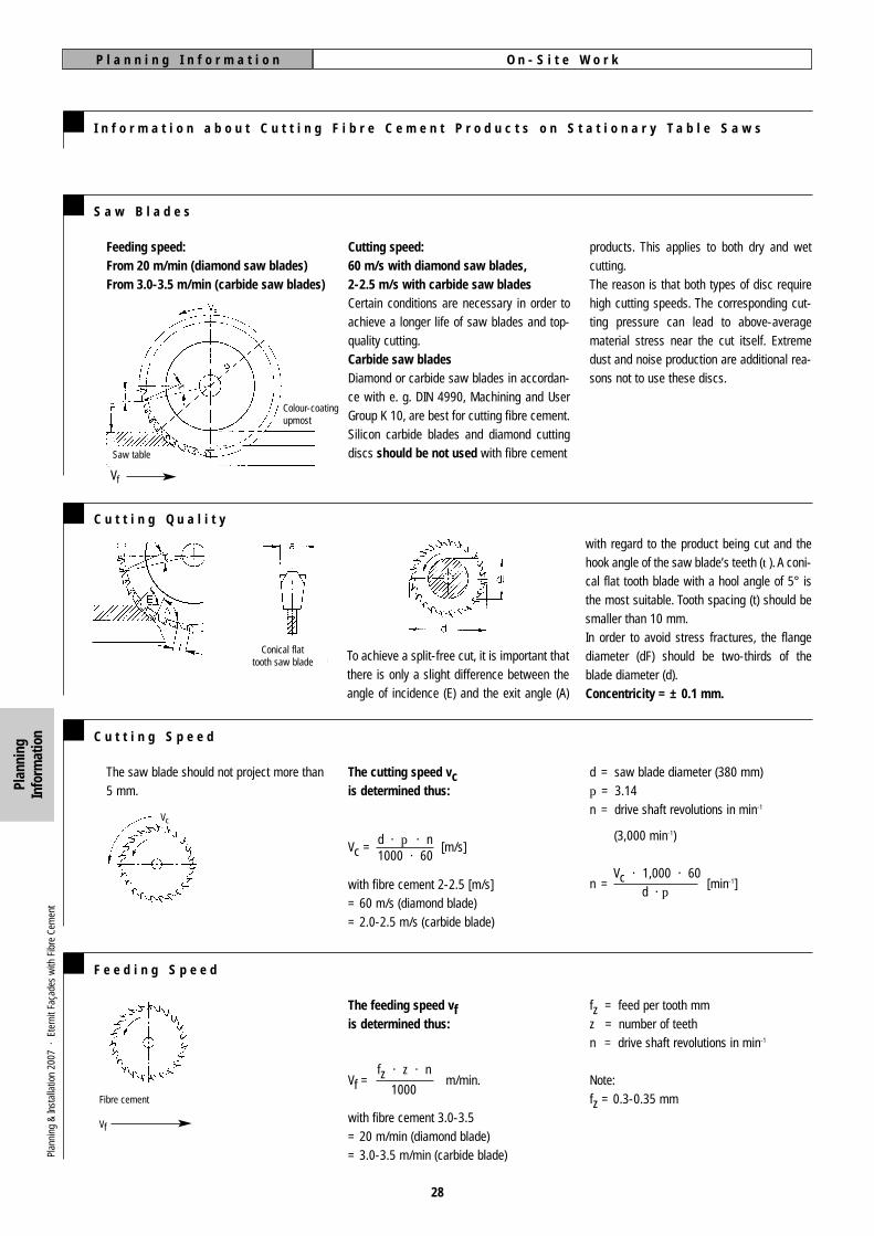
The feeding speed vfis determined thus:
Vf = m/min.
with fibre cement 3.0-3.5 = 20 m/min (diamond blade)= 3.0-3.5 m/min (carbide blade)
d = saw blade diameter (380 mm)p = 3.14n = drive shaft revolutions in min-1
(3,000 min-1)
Vc · 1,000 · 60d · p
n = [min-1]
28
I n f o r m a t i o n a b o u t C u t t i n g F i b r e C e m e n t P r o d u c t s o n S t a t i o n a r y T a b l e S a w s
S a w B l a d e s
products. This applies to both dry and wetcutting.The reason is that both types of disc requirehigh cutting speeds. The corresponding cut-ting pressure can lead to above-averagematerial stress near the cut itself. Extremedust and noise production are additional rea-sons not to use these discs.
C u t t i n g S p e e d
Cutting speed:60 m/s with diamond saw blades,2-2.5 m/s with carbide saw bladesCertain conditions are necessary in order toachieve a longer life of saw blades and top-quality cutting.Carbide saw bladesDiamond or carbide saw blades in accordan-ce with e. g. DIN 4990, Machining and UserGroup K 10, are best for cutting fibre cement.Silicon carbide blades and diamond cuttingdiscs should be not used with fibre cement
The cutting speed vcis determined thus:
Vc = [m/s]
with fibre cement 2-2.5 [m/s]= 60 m/s (diamond blade)= 2.0-2.5 m/s (carbide blade)
fz = feed per tooth mmz = number of teethn = drive shaft revolutions in min-1
Note:fz = 0.3-0.35 mm
F e e d i n g S p e e d
The saw blade should not project more than5 mm.
d · p · n1000 · 60
fz · z · n
1000
Colour-coatingupmost
Saw table
Vc
Fibre cement
Vf
P l a n n i n g I n f o r m a t i o n O n - S i t e W o r k
t
Vf
C u t t i n g Q u a l i t y
To achieve a split-free cut, it is important thatthere is only a slight difference between theangle of incidence (E) and the exit angle (A)
with regard to the product being cut and thehook angle of the saw blade’s teeth (t). A coni-cal flat tooth blade with a hool angle of 5° isthe most suitable. Tooth spacing (t) should besmaller than 10 mm.In order to avoid stress fractures, the flangediameter (dF) should be two-thirds of theblade diameter (d).Concentricity = ± 0.1 mm.
Conical flattooth saw blade
Feeding speed: From 20 m/min (diamond saw blades)From 3.0-3.5 m/min (carbide saw blades)
Plan
ning
&In
stal
latio
n 20
07 ·
Ete
rnit
Faça
des
with
Fib
re C
emen
t
Plan
ning
Info
rmat
ion
E d g e F i n i s h i n g a f t e r S a w i n gI n s t r u c t i o n
29
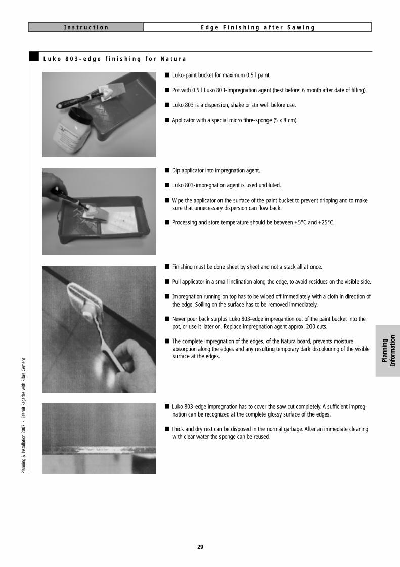
L u k o 8 0 3 - e d g e f i n i s h i n g f o r N a t u r a
Plan
ning
&In
stal
latio
n 20
07 ·
Ete
rnit
Faça
des
with
Fib
re C
emen
t
■ Luko-paint bucket for maximum 0.5 l paint
■ Pot with 0.5 l Luko 803-impregnation agent (best before: 6 month after date of filling).
■ Luko 803 is a dispersion, shake or stir well before use.
■ Applicator with a special micro fibre-sponge (5 x 8 cm).
■ Dip applicator into impregnation agent.
■ Luko 803-impregnation agent is used undiluted.
■ Wipe the applicator on the surface of the paint bucket to prevent dripping and to makesure that unnecessary dispersion can flow back.
■ Processing and store temperature should be between +5°C and +25°C.
■ Finishing must be done sheet by sheet and not a stack all at once.
■ Pull applicator in a small inclination along the edge, to avoid residues on the visible side.
■ Impregnation running on top has to be wiped off immediately with a cloth in direction ofthe edge. Soiling on the surface has to be removed immediately.
■ Never pour back surplus Luko 803-edge impregantion out of the paint bucket into the pot, or use it later on. Replace impregnation agent approx. 200 cuts.
■ The complete impregnation of the edges, of the Natura board, prevents moistureabsorption along the edges and any resulting temporary dark discolouring of the visiblesurface at the edges.
■ Luko 803-edge impregnation has to cover the saw cut completely. A sufficient impreg-nation can be recognized at the complete glossy surface of the edges.
■ Thick and dry rest can be disposed in the normal garbage. After an immediate cleaning with clear water the sponge can be reused.
Plan
ning
Info
rmat
ion

O n - S i t e W o r kP l a n n i n g I n f o r m a t i o n
30
I n f o r m a t i o n C o n c e r n i n g t h e O n - S i t e P r e p a r a t i o n o f F i b r e C e m e n t P r o d u c t s
S i t e T o o l s
To this end the german Fibre Cement IndustryAssociation has funded and promoted thedevelopment of dust-free tools.
Fibre cement products can be delivered in aready-to-use state, i. e. ready to install, sothat only on-site cutting to size is necessary.
Hand Saws
Compass saw (complete) ABC
Saw blade (quick-change) + grip
Weight: approx. 0.2 kg
Jigsaws
Consisting of:
Steel saw blade, cut withaot “oscillating”.
Recommendation: Bosch T 141 HM
saw blade
Vacuum CleanersCircular SawsRivet Setters
Cordless rivet setter: „GESIPA Accubird“
holes can become apparent as a darker shadein wet weather. Depending on seasonal weat-her conditions, this effect disappears duringdry periods.
The edges of Natura panels that have been cuton-site must be impregnated. The edges of allfactory-cut Natura panels have to be impreg-nated Luko edge sealant at the factory. Insemi-transparent coatings (e. g. Natura), moi-sture ingress at the panel edges and predrilled
It is advisable to sand the edges of panels aftercutting them to size. This reduces the possibi-lity of damage and improves their appearance.A block of wood, approx. 400 x 100 mm insize, with a piece of sandpaper (80-grit) affi-xed to it can be used to sand the edges.
E d g e F i n i s h
Heavy-duty rivet setter: „GESIPA HN 2“
General-duty rivet setter „Format“Plan
ning
&In
stal
latio
n 20
07 ·
Ete
rnit
Faça
des
with
Fib
re C
emen
t
Festo plunge-cut saw AXT 50 LA
Power input: 750 Watt
RPM: 210 U/min.
Weight: approx. 6.4 kg
– Festo guide rail, 3 m
– mafell portable panel saw system PSS
3100 SE with guide track and diamond
saw blade
Festo special vacuum cleaner SRH 204 E-AS
Power input: 350 - 1,200 W
RPM: max 3,400 l/min
Weight: 14.5 kg
www.festool.de
Plan
ning
Info
rmat
ion

T i m b e r F r a m e w o r kP l a n n i n g I n f o r m a t i o n
31
G e n e r a l N o t e s
Timber battens of Class C 24 (formaly S 10) inaccordance with e. g. DIN 4074-1 are to beused for the subframe on which the panels arto be fixed.
W o o d P r e s e r v a t i o n
T y p e s o f C o n s t r u c t i o n
Timber subframes must be treated with awood preservative in accordance with e. g.DIN 68800-2. Battens and counter battens ofhazard class (GK) 0 do not need preventivechemical tratment against fungal or insectattack, subject to the conditions stated inaccordance with e. g. DIN 68800-2.Dispensing with the preventive chemical treat-ment of timber is an important contribution tothe environment.
Battens and counter battens satisfy hazardclass 0 if:– the moisture content at the time of fixing
µ1 < 20 % or if it has been ensured that the wood will dry out to this moisturecontent within a period of six monthsfrom then.
– if suitable measures have been taken toensure that the moisture content of thewood when in use does not regularly
exceed 20 %. These include measures toprotect in from wetness when in use(e. g. splashing), moisture from adjoiningparts of the building (drainage layers)and condensation (proof of compliance inaccordance with e. g. DIN 4108-3).
If these conditions cannot be met, the frame-work must be protected in accordance with e. g. DIN 68800-3 “Protection of Timber Usedin Buildings, Chemical Preventive Protection”.
Standard construction Battens fixed with plugs Timber subframe with supporting brackets
To accommodate insulation of a greaterthickness, the vertical battens can be suppor-ted on metal brackets or U-shaped connectorswith a thermal break. The connectors must beresistant to corrosion caused by the wood pre-servative used.
Vertical battens laid on insulation withoutbrackets. The dead weight of the constructionis borne by suitable plugs fixing the subframe.Insulation to be fixed with fasteners as per themanufacturer’s specifications.
With vertical battens. Insulation between hori-zontal counter battens. It is obligatory to fix theinsulation with insulation fasteners, wherebyadhesive fixing is also permissible.
For further details, see www.eternit.de
– Anchors
– Insulation, insulation fasteners
For anchoring the subconstruction on the sup-porting structure, approved plugs or plug-and-screw combinations must be used. The stipu-lations of the corresponding approval certifica-tion must be observed.
Exterior wall cladding on timber subframesusually consists of the following components:
– Cladding
– Timber battens for fixing
– Counter battens or metal brackets
– Fasteners
Plan
ning
&In
stal
latio
n 20
07 ·
Ete
rnit
Faça
des
with
Fib
re C
emen
t Layi
ng

T i m b e r S u b f r a m eP l a n n i n g I n f o r m a t i o n
32
F r a m e w o r k F a s t e n e r s
F a s t e n e r s
Minimum dimensions of battens and associa-ted screw or nail positioning:
PositioningTwo fasteners on the diagonal at each inter-section of battens. The fixing battens usuallyrun vertically.
The batten widths relate exclusively to thefixing centres shown. Depending on the typeand positioning of plugs (anchoring in theexterior walls) and the positioning of a battenbehind a panel joint, wider battens may benecessary.
Counter batten
Counter batten
Batten
Batten
Fastener
Fastener
≥30
≥ 5 dn
≥ 5 dn ≥ 5 dn
≥ 7 dn
≥30
Nails with smooth shanks are not permissiblefor this application.
Fasteners in accordance with e. g. DIN 1052-2 such as special nails (with a ring or spiralshank) are to be used for fixing battens andcounter battens.
General building regulations approval is requi-red for the use of special screws and clamps.
Plan
ning
&In
stal
latio
n 20
07 ·
Ete
rnit
Faça
des
with
Fib
re C
emen
t
Batten
Counter batten
Insulation
Fastener
Anchor
Layi
ng
F i x i n g t o T i m b e r S u b f r a m e s
The panels are to be mounted free of endrestraint. Changes of shape should not be ableto result in indirect loads that could damage
the cladding ot the subframe at ties and fixing-points. Unrestrained support of the panels onwooden subframes can be achieved if all of a
panel’s fixing holes are drilled with diametersapprox. 2 mm larger than the shaft diameter ofthe fasteners.
C o l o u r e d F a ç a d e S c r e wEternit façade screw, building regulationsapproved. Failure to use this screw invalidatesthe warranty. 1– 5.5 x 35 mm for 8 mm façade panels,– 5.5 x 45 mm for 12 mm façade panels andfor visible weatherboard fixing with 8 mmpanels, stainless steel, material no. 1.4567 inaccordance with e. g. DIN 1654-5 with T 20hex socket cap screw. Minimum screw depthof 25 mm in each case.The battens must be chosen such that thedistance of the screws from the edge of thebatten is not less than 15 mm.The fixing hole must be drilled with a diameter2 mm larger than the shaft diameter. ForEternit façade screws, the panels are to bepre-drilled with Ø 6 mm using the Eternit spe-cial drill. 2
EPDM- or black-coatedAlu-Sealing strip
≥ 30
≥ 8-10≥ 20
≥ 15≥ 5
~ 100
1 Eternit Façade screw, page 642 Eternit special drill for fibre cement Ø 6 mm, page 65
I n s t a l l a t i o n o n T i m b e r S u b f r a m e sP l a n n i n g I n f o r m a t i o n
33
M i n i m u m S p a c i n g o f F a s t e n e r s o n a W o o d e n S u b f r a m e
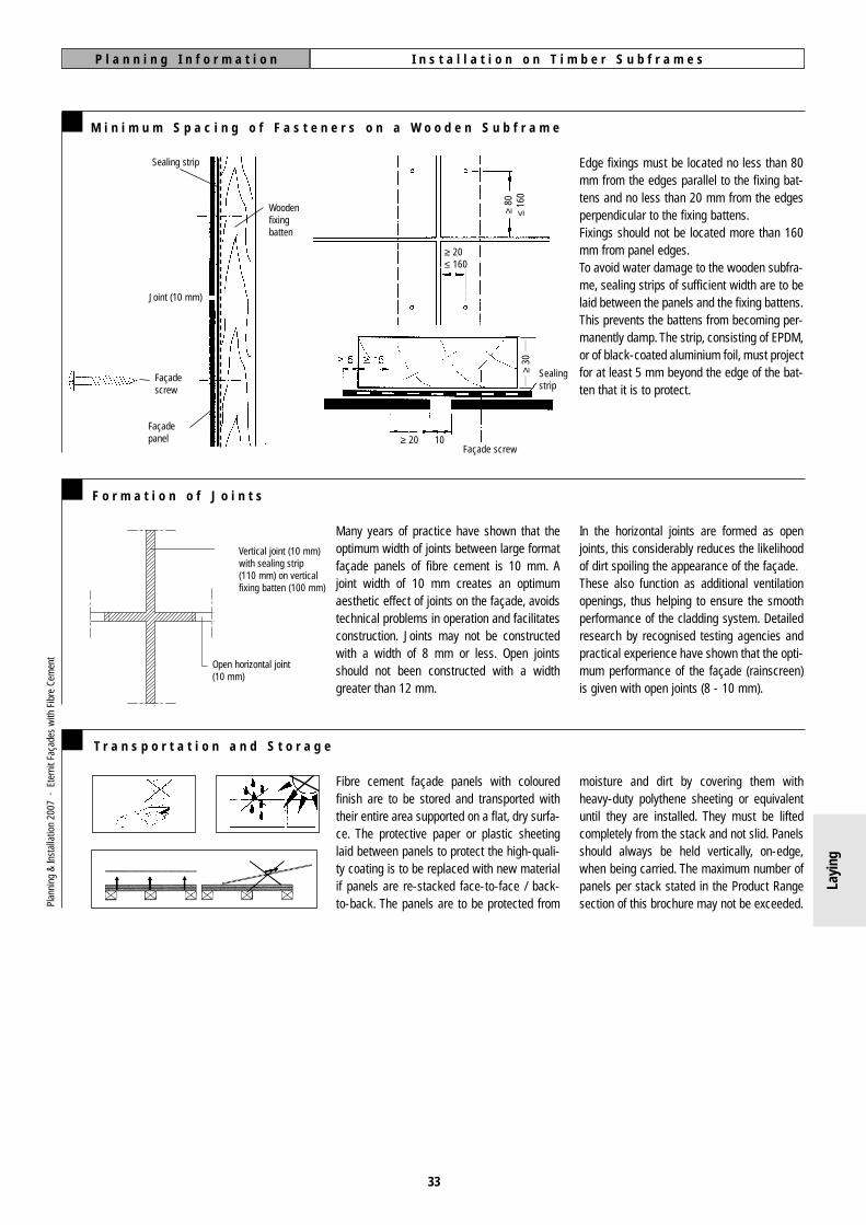
Edge fixings must be located no less than 80mm from the edges parallel to the fixing bat-tens and no less than 20 mm from the edgesperpendicular to the fixing battens.Fixings should not be located more than 160mm from panel edges.To avoid water damage to the wooden subfra-me, sealing strips of sufficient width are to belaid between the panels and the fixing battens.This prevents the battens from becoming per-manently damp. The strip, consisting of EPDM,or of black-coated aluminium foil, must projectfor at least 5 mm beyond the edge of the bat-ten that it is to protect.
≥ 20≤ 160
≥ 20 10
≥80
≤16
0
Sealing strip
Façadescrew
Façadepanel
Joint (10 mm)
Woodenfixingbatten
Sealingstrip
Façade screw
≥30
F o r m a t i o n o f J o i n t s
Many years of practice have shown that theoptimum width of joints between large formatfaçade panels of fibre cement is 10 mm. Ajoint width of 10 mm creates an optimumaesthetic effect of joints on the façade, avoidstechnical problems in operation and facilitatesconstruction. Joints may not be constructedwith a width of 8 mm or less. Open jointsshould not been constructed with a widthgreater than 12 mm.
In the horizontal joints are formed as openjoints, this considerably reduces the likelihoodof dirt spoiling the appearance of the façade.These also function as additional ventilationopenings, thus helping to ensure the smoothperformance of the cladding system. Detailedresearch by recognised testing agencies andpractical experience have shown that the opti-mum performance of the façade (rainscreen)is given with open joints (8 - 10 mm).
Open horizontal joint(10 mm)
Vertical joint (10 mm)with sealing strip (110 mm) on verticalfixing batten (100 mm)
Plan
ning
&In
stal
latio
n 20
07 ·
Ete
rnit
Faça
des
with
Fib
re C
emen
t
Layi
ng
T r a n s p o r t a t i o n a n d S t o r a g e
Fibre cement façade panels with colouredfinish are to be stored and transported withtheir entire area supported on a flat, dry surfa-ce. The protective paper or plastic sheetinglaid between panels to protect the high-quali-ty coating is to be replaced with new materialif panels are re-stacked face-to-face / back-to-back. The panels are to be protected from
moisture and dirt by covering them withheavy-duty polythene sheeting or equivalentuntil they are installed. They must be liftedcompletely from the stack and not slid. Panelsshould always be held vertically, on-edge,when being carried. The maximum number ofpanels per stack stated in the Product Rangesection of this brochure may not be exceeded.

M o u n t i n g L a r g e S i z e F a ç a d e P a n e l sD e s i g n I n f o r m a t i o n
34
F i n a l C l e a n i n g
The final cleaning of the façade is to be carriedout using sponges and water from a hosepipeas the scaffolding is dismantled. If a cleaningagent is to be added, this should be a stan-dard, commercially available dish-washing
liquid. High-pressure cleaners set to a reducedpressure can also be used. Lime specks orsplashes of cement are to be treated with a 5 % malic acid solution and washed off withplenty of water. It is important that not malic
acid comes into contact with bare metal surfa-ces. fibre cement dust can be removed easilywith a microfibre cloth.
S c a f f o l d i n g A n c h o r s
Any panels mounted adjacent to a scaffoldinganchor should be secured subsequently withEternit fasteners as the scaffolding is dismant-led. If this is not possible, the holes in the faça-
de panel should be left open. Gluing-in scaffol-ding ties is not permissible.
P r o t e c t i o n a g a i n s t V a n d a l i s m
12 mm thick Structura façade panels meet therequirements for “safety against ballthrowing”laid down in accordance with e. g. DIN 18032,Sports Halls – Halls of Gymnastics, Games and
Multi-Purpose Use – Part 3.Certificate of testing from FMPA, Baden-Württemberg, No. 46/28260.Construction details:
Joint width 10 mm, vertical support battens(50 x 30 mm / 100 x 30 mm), façade screw,5.5 x 45 mm, screw spacing 408 mm (vertical)and 605 mm (horizontal).
The thickness of the sealing strip may notexceed 0.8 mm. The strip should be fixedsufficiently to prevent it slipping.The use of horizontal sealing strips is likelyto increase the accumulation of dirt.Material: painted, plastic or powder-coatedaluminium.
Care should be taken not to lay one layer ofsealing strip over another.1 Crimped profile / 2 L profile /3 without backing at the joint
C o r n e r P r o f i l e s a n d J o i n t P r o f i l e s
Only corner profiles that do not result in dis-placement may be used. Care must be takento avoid coupling across movement joints.
1Material: painted, plastic or powder-coatedaluminium.
1 2 3
Reusable scaffoldinganchor fixed throughthe joints.
1 Movement joint without coupling, page 38
Plan
ning
&In
stal
latio
n 20
07 ·
Ete
rnit
Faça
des
with
Fib
re C
emen
t
Layi
ng

F i x i n g t o a T i m b e r S u b c o n s t r u c t i o nD e s i g n I n f o r m a t i o n
35
C e n t r e S p a c i n g
than those given here. In general, edgedistances should not be greater than 160 mm.In certain situations, however, e. g. above rol-ler-blind headboxes, edge distances of up to200 mm are permissible. If the edge distancesare greater than 160 mm, differences in thealignment of adjacent panels can occur. Thisdoes not affect their structural stability.
The following fixing tables offer non-bindingrecommendations for maximum panel dimen-sions in practice. A structural analysis and anyconstruction planning based on it must be cal-culated with reference to the object itself in allcases. The spacing of fixings is influenced bythe choise of subconstruction, supports andanchoring. The edge distances may not be less
Minimum Edge Distances on Timber Subconstruction
1,250
80
20 20
80
a = 2 x 605
b =
3 x
780
2,50
0
Example
Parameters:– Height of building H ≤ 8 m– Timber subconstruction– Panels mounted vertically on vertical
battens– Panel format (H x W) 2,500 x 1,250 mm– Panel thickness 8 mm– Standard zone of the building
From Table 1 on next page (outlined):a = 2 x 605 mm = horizontal centre spacingb = 3 x 780 mm = vertical centre spacing
F i x i n g N a r r o w F i b r e C e m e n t S t r i p s ( 8 m m t h i c k )
The number of fasteners per row depends on the length of the strip and the height of the building.
Timber SubconstructionHorizontal batten fixing Vertical batten fixing
Width 60 mm or more,a = 30 mm
Width 100 mm or more,central fixing, a = 50 mm
Eccentricfixing
20 mm ≤ a ≤ 80 mm
Width up to 300 mm,central fixing, a = 150 mm
Eccentricfixing
40 mm ≤ a ≤ 150 mm
Width 120 mm or more,centre spacind, b ≥ 80 mm
Width 160 mm or more,a = 80 mm
Width ab 240 mm or more,central fixing, a = 120 mm
Eccentricfixing
80 mm ≤ a ≤ 160 mm
Width up to 300 mm,central fixing a = 150 mm
Eccentricfixing
80 mm ≤ a ≤ 150 mm
Width 240 mm or more,centre spacing, b ≥ 80 mm
Narrowest strip format,up to 1.00 m in length,with one row of fixings
Narrowest strip format,up to 3.10 m in length,with one row of fixings
Widest strip format,up to max. 3.10 m in length,with one row of fixings
Narrowest strip format,up to max. 3.10 m in length,with two rows of fixings
Plan
ning
&In
stal
latio
n 20
07 ·
Ete
rnit
Faça
des
with
Fib
re C
emen
t
fibre cementfaçade panel
Timber subconstruction
≥80
≤16
0
≥ 20≤ 160
EPDM or coated aluminium sealingstrip on timber subconstruction
Layi
ng
F i x i n g o n T i m b e r S u b c o n s t r u c t i o nD e s i g n I n f o r m a t i o n
36
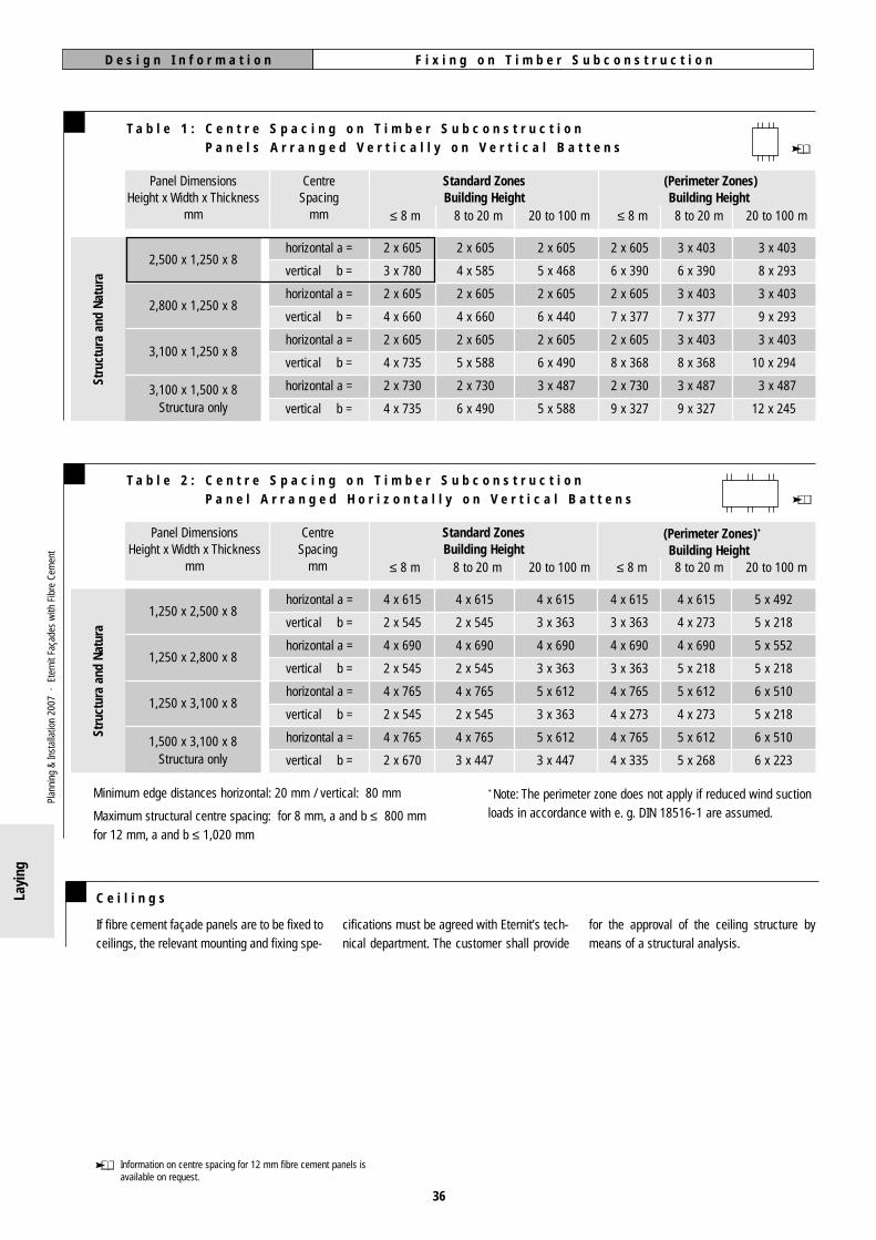
T a b l e 1 : C e n t r e S p a c i n g o n T i m b e r S u b c o n s t r u c t i o nP a n e l s A r r a n g e d V e r t i c a l l y o n V e r t i c a l B a t t e n s
Standard ZonesBuilding Height
(Perimeter Zones)Building Height
2,500 x 1,250 x 8
2,800 x 1,250 x 8
3,100 x 1,250 x 8
3,100 x 1,500 x 8Structura only
horizontal a =
vertical b =
horizontal a =
vertical b =
horizontal a =
vertical b =
horizontal a =
vertical b =
Minimum edge distances horizontal: 20 mm / vertical: 80 mm +Note: The perimeter zone does not apply if reduced wind suctionloads in accordance with e. g. DIN 18516-1 are assumed.Maximum structural centre spacing: for 8 mm, a and b ≤ 800 mm
for 12 mm, a and b ≤ 1,020 mm
CentreSpacing
mm
Panel DimensionsHeight x Width x Thickness
mm ≤ 8 m
2 x 605
3 x 780
2 x 605
4 x 660
2 x 605
4 x 735
2 x 730
4 x 735
8 to 20 m
2 x 605
4 x 585
2 x 605
4 x 660
2 x 605
5 x 588
2 x 730
6 x 490
20 to 100 m
2 x 605
5 x 468
2 x 605
6 x 440
2 x 605
6 x 490
3 x 487
5 x 588
≤ 8 m
2 x 605
6 x 390
2 x 605
7 x 377
2 x 605
8 x 368
2 x 730
9 x 327
8 to 20 m
3 x 403
6 x 390
3 x 403
7 x 377
3 x 403
8 x 368
3 x 487
9 x 327
20 to 100 m
3 x 403
8 x 293
3 x 403
9 x 293
3 x 403
10 x 294
3 x 487
12 x 245
T a b l e 2 : C e n t r e S p a c i n g o n T i m b e r S u b c o n s t r u c t i o nP a n e l A r r a n g e d H o r i z o n t a l l y o n V e r t i c a l B a t t e n s
Standard ZonesBuilding Height
(Perimeter Zones)+
Building Height
1,250 x 2,500 x 8
1,250 x 2,800 x 8
1,250 x 3,100 x 8
1,500 x 3,100 x 8Structura only
horizontal a =
vertical b =
horizontal a =
vertical b =
horizontal a =
vertical b =
horizontal a =
vertical b =
CentreSpacing
mm
Panel DimensionsHeight x Width x Thickness
mm ≤ 8 m
4 x 615
2 x 545
4 x 690
2 x 545
4 x 765
2 x 545
4 x 765
2 x 670
8 to 20 m
4 x 615
2 x 545
4 x 690
2 x 545
4 x 765
2 x 545
4 x 765
3 x 447
20 to 100 m
4 x 615
3 x 363
4 x 690
3 x 363
5 x 612
3 x 363
5 x 612
3 x 447
≤ 8 m
4 x 615
3 x 363
4 x 690
3 x 363
4 x 765
4 x 273
4 x 765
4 x 335
8 to 20 m
4 x 615
4 x 273
4 x 690
5 x 218
5 x 612
4 x 273
5 x 612
5 x 268
20 to 100 m
5 x 492
5 x 218
5 x 552
5 x 218
6 x 510
5 x 218
6 x 510
6 x 223
Information on centre spacing for 12 mm fibre cement panels isavailable on request.
Stru
ctur
a an
d Na
tura
Stru
ctur
a an
d Na
tura
C e i l i n g s
If fibre cement façade panels are to be fixed toceilings, the relevant mounting and fixing spe-
cifications must be agreed with Eternit’s tech-nical department. The customer shall provide
for the approval of the ceiling structure bymeans of a structural analysis.
Plan
ning
&In
stal
latio
n 20
07 ·
Ete
rnit
Faça
des
with
Fib
re C
emen
t
Layi
ng
wing page in alphabetical order. In addition,manufacturer’s own subconstructions areavailable in a number of variants on a regionalbasis. 2
Internal ForcesThe internal forces, in particular the maximumbending moments and the bearing reactionsmust be calculated for the proof of structuralstability of large-size Eternit façade panels andtheir fixings.Structurally, the resilience of aluminium sub-constructions is to be taken into account. Inthe case of wind pressure this is generallytaken up linearly by the subconstruction.As regards wind suction, the panels lie onrounded bearings, which are formed by theheads of rivets or screws.
A variety of aluminium subconstructions areavailable for mounting cladding on new andrefurbished façades. As a rule, their structuralstability is to be proven by structural analysison the basis of the applicable TechnicalBuilding Regulations. In the case of systemsthat cannot be calculated, such as clampfixing, general building regulations approvalfor the construction is required.
The components of exterior cladding on metalsubconstruction are, as a rule:
– cladding
– fixings
– support profile
– fasteners
– brackets
– anchors
– complementary components
– insulation, insulation fixings
A l u m i n i u m S u b c o n s t r u c t i o nP l a n n i n g I n f o r m a t i o n
G e n e r a l N o t e s
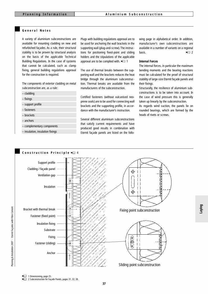
C o n s t r u c t i o n P r i n c i p l e 4
Plugs with building regulations approval are tobe used for anchoring the wall brackets in thesupporting wall (plug-and-screw). The instruc-tions for positioning fixed-point and slidingholders and the stipulations of the applicableapproval are to be complied with. 1
The use of thermal breaks between the sup-porting wall and the brackets reduces the heatbridge through the aluminium subconstruc-tion. Thermal breaks are available from themanufacturers of the subconstruction.
Certified fasteners (without vulcanised neo-prene seals) are to be used for connecting wallbrackets and the supporting profile, in accor-dance with the manufacturer’s instruction.
Several different aluminium subconstructionsthat satisfy current requirements and haveproduced good results in combination withEternit façade panels are listed on the follo-
1 Dimensioning, page 25.2 Subconstruction for Façade Panels, pages 31, 32, 38.
Support profile
Cladding / façade panel
Ventilation gap
Insulation
Bracket with thermal break
Fastener (fixed point)
Insulation fixing
Substrate
Fixing
Fastener (sliding)
Anchor
Sliding point subconstruction
Fixing point subconstruction
37
h
h
Plan
ning
&In
stal
latio
n 20
07 ·
Ete
rnit
Faça
des
with
Fib
re C
emen
t
Layi
ng

A l u m i n i u m S u b c o n s t r u c t i o nP l a n n i n g I n f o r m a t i o n
38
P o s i t i o n i n g P a n e l s o n t h e S u b c o n s t r u c t i o n
At movement joints in the subconstruction, thesame movements must be possible in thecladding. In order to avoid displacement con-straint arising from the coupling of individualpanels by vertical aluminium support profiles,no butt joints of these profiles may be lie bet-ween the fixing points of a panel.
If panels are coupled by aluminium supportprofiles, this causes damage due to displace-ment constraint.
The support profiles of the subconstructionmust be aligned such that the façade panelslie flat in the same plane and can be fixedwithout displacement constraint.
At the same time, a panel may only be fixed tosupport profiles that have fixed points lying atthe same height.
This means that profiles must be cut throughat window sills, for example, in order to avoidprofile butt joints beneath individual panels
S u b c o n s t r u c t i o n f o r F a ç a d e P a n e l s : A d d r e s s e s o f M a n u f a c t u r e r s a n d S u p p l i e r s
BWM-Dübel + Montagetechnik GmbHErnst-Mey-Strasse 1D-70771 Leinfelden/Echterdingen, GermanyTelephone +49 711 / 90 313-0Fax +49 711 / 90 313-20E-Mail: [email protected]: www.bwm.de
NAUTH-Fassadentechnik GmbHWeinstrasse 686D-76887 Bad Bergzabern, GermanyTelephone +49 63 43 / 70 03-0Fax +49 63 43 / 70 03-20E-Mail: [email protected]: www.nauth.de
Montaflex GmbHAm Hafen 36D-38112 Braunschweig, GermanyTelephone +49 5 31 / 2 10 22-0Fax +49 5 31 / 2 10 22-20E-Mail: [email protected]: www.montaflex.de
Systea DWS Pohl GmbHMargarete-Steiff-Strasse 6D-24558 Henstedt-Ulzburg, GermanyTelephone +49 41 93 / 99 11 0Fax +49 41 93 / 99 11 49E-Mail: [email protected]: www.pohlnet.com
WS Fassadenelemente GmbHBrackestrasse 1D-38159 Vechelde, GermanyTelephone +49 53 02 / 91 91-0Fax +49 53 02 / 91 91-49E-Mail: [email protected]: www.wagnersystem.de
The formation of outer corner profiles musttake into account the same coupling-freemovement joints as in the subconstruction.
Fixing point subconstruction
Sliding point subconstruction
≥20
Plan
ning
&In
stal
latio
n 20
07 ·
Ete
rnit
Faça
des
with
Fib
re C
emen
t
Movement joint in thesubconstruction
Fastener
JointSubconstruction
Layi
ng
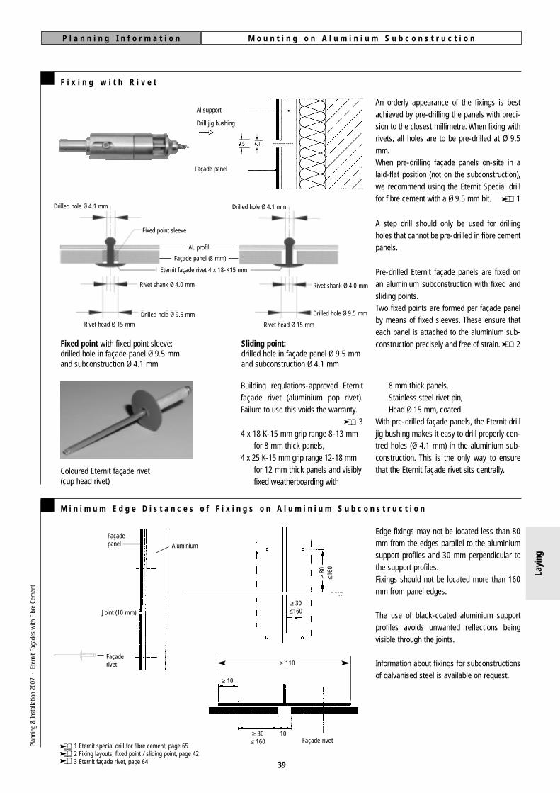
M o u n t i n g o n A l u m i n i u m S u b c o n s t r u c t i o nP l a n n i n g I n f o r m a t i o n
39
F i x i n g w i t h R i v e t
An orderly appearance of the fixings is bestachieved by pre-drilling the panels with preci-sion to the closest millimetre. When fixing withrivets, all holes are to be pre-drilled at Ø 9.5mm.When pre-drilling façade panels on-site in alaid-flat position (not on the subconstruction),we recommend using the Eternit Special drillfor fibre cement with a Ø 9.5 mm bit. 1
Pre-drilled Eternit façade panels are fixed onan aluminium subconstruction with fixed andsliding points.Two fixed points are formed per façade panelby means of fixed sleeves. These ensure thateach panel is attached to the aluminium sub-construction precisely and free of strain. 2
A step drill should only be used for drillingholes that cannot be pre-drilled in fibre cementpanels.
M i n i m u m E d g e D i s t a n c e s o f F i x i n g s o n A l u m i n i u m S u b c o n s t r u c t i o n
Façaderivet
Façadepanel
Joint (10 mm)
Aluminium
≥ 30≤160
≥80
≤160
Façade rivet
≥ 10
≥ 30≤ 160
10
Edge fixings may not be located less than 80mm from the edges parallel to the aluminiumsupport profiles and 30 mm perpendicular tothe support profiles.Fixings should not be located more than 160mm from panel edges.
The use of black-coated aluminium supportprofiles avoids unwanted reflections beingvisible through the joints.
Information about fixings for subconstructionsof galvanised steel is available on request.
1 Eternit special drill for fibre cement, page 65 2 Fixing layouts, fixed point / sliding point, page 423 Eternit façade rivet, page 64
≥ 110
8 mm thick panels.Stainless steel rivet pin,Head Ø 15 mm, coated.
With pre-drilled façade panels, the Eternit drilljig bushing makes it easy to drill properly cen-tred holes (Ø 4.1 mm) in the aluminium sub-construction. This is the only way to ensurethat the Eternit façade rivet sits centrally.
Fixed point with fixed point sleeve:drilled hole in façade panel Ø 9.5 mmand subconstruction Ø 4.1 mm
Coloured Eternit façade rivet(cup head rivet)
Sliding point:drilled hole in façade panel Ø 9.5 mmand subconstruction Ø 4.1 mm
AL profil
Façade panel (8 mm)
Eternit façade rivet 4 x 18-K15 mm
Rivet shank Ø 4.0 mm
Fixed point sleeve
Drilled hole Ø 4.1 mm
Façade panel
Al support
Drill jig bushing
Drilled hole Ø 4.1 mm
Drilled hole Ø 9.5 mm
Rivet head Ø 15 mmRivet head Ø 15 mm
Drilled hole Ø 9.5 mm
Rivet shank Ø 4.0 mm
Building regulations-approved Eternitfaçade rivet (aluminium pop rivet).Failure to use this voids the warranty.
34 x 18 K-15 mm grip range 8-13 mm
for 8 mm thick panels,4 x 25 K-15 mm grip range 12-18 mm
for 12 mm thick panels and visiblyfixed weatherboarding with
Plan
ning
&In
stal
latio
n 20
07 ·
Ete
rnit
Faça
des
with
Fib
re C
emen
t
Layi
ng

M o u n t i n g o n A l u m i n i u m S u b c o n s t r u c t i o nP l a n n i n g I n f o r m a t i o n
C h o o s i n g t h e T w o F i x e d P o i n t s
The two fixed points are formed by means offixed point sleeves. This ensures that the panelis attached to the aluminium subconstructionprecisely and free of strain.The two fixed points of a panel may never beset on the same support profile (with theexception of weatherboarding on a horizontalsupport profile). This results in the alignment of
the fixed points being perpendicular (at rightangles to) the run of the support profile.The two fixed points must be set as centrally aspossible in the panel.Each fixed point is (if possible) attached to thesecond support profile in from the panel edge,on both the right and the left.
S e t t i n g E t e r n i t F a ç a d e R i v e t s
Eternit façade rivets are set without a rivetingjig (irrespective of whether they are for slidingpoints or the two fixed ones).To form a fixed point, the Eternit façade rivet istset together with the fixed point sleeve in oneoperation. Care should be taken to ensure thatthe rivet head lies flat on the façade panel. Thenose piece and the chuck jaw (4.0 mm rivetshank diameter) of the riveting tool are to be
chosen such that the rivet head is not dama-ged. Both of the fixed points and at least twosliding points are necessary to guarantee exactalignment of the façade panels at their joints.Drilling and setting of rivets should be done insequence, beginning with fixed points, thenupper sliding points and lastly the lower slidingpoints. All sliding points are formed withoutfixed point sleeves.
B a c k e d V e r t i c a l a n d H o r i z o n t a l J o i n t s( E x a m p l e w i t h A l u m i n i u m S u b c o n s t r u c t i o n )
If the joints are to be formed with backing, thiscan be done using backing sections in coatedaluminium of the type shown. Their thicknessmay not exceed 0.8 mm. At cross-joints, metalbacking sections may not be laid on top ofeach other.
The joint profiles can be produced in black orin colours to match the façade panels.If horizontal joint profiles are used, a greateramount of dirt is likely to accumulate in anirregular way on the exterior wall.
A v o i d i n g D i s p l a c e m e n t C o n s t r a i n t s
able, the required edge distance is to be mea-sured from this point.
in the illustration below. If an additional thick-ness of more than 0.8 mm proves unavoid-
Construction details should be designed suchas to avoid displacement constraint, as shown
Fastener layouts, page 42
Al supportprofile
Crimpedprofile
40
Plan
ning
&In
stal
latio
n 20
07 ·
Ete
rnit
Faça
des
with
Fib
re C
emen
t
Layi
ng

M o u n t i n g o n A l u m i n i u m S u b c o n s t r u c t i o nP l a n n i n g I n f o r m a t i o n
41
C e n t r e S p a c i n g
than those given here. In general, edgedistances should not be greater than 160 mm.In certain situations, however, e. g. above rol-ler-blind headboxes, edge distances of up to200 mm are permissible. If the edge distancesare greater than 160 mm, differences in thealignment of adjacent panels can occur. Thisdoes not affect their structural stability.
The following fixing tables contain non-bindingrecommendations for maximum dimensions ofpanel sizes in practice. Structural analysis, andany construction planning based on it, must becalculated with reference to the object itself inall cases. The spacing of fixings is influencedby the choise of subconstruction, supports andanchoring. The edge distances may not be less
Façadepanel
AL-UK≥ 30
Minimum Edge Distances on Aluminium Subconstruction
≥80
≤16
0
F i x i n g N a r r o w F i b r e C e m e n t S t r i p s ( 8 m m t h i c k )
The number of fasteners per row depends on the length of the strip and the height of the building.
Aluminium SubconstructionHorizontal support profile Vertical support profile
Width 60 mm or more,a = 30 mm
Width 100 mm or more,central fixing,a = 50 mm
Eccentricfixing
30 mm ≤ a ≤ 70 mm
Width up to 300 mm,central fixing,a = 150 mm
Eccentricfixing
40 mm ≤ a ≤ 150 mm
Width 140 mm or more,centre spacing
b ≥ 80 mm
Width 160 mm or more,a = 80 mm
Width 160 mm or more,central fixing,a = 80 mm
Eccentricfixing,
80 mm ≤ a ≤ 160 mm
Width up to 300 mm,central fixing,a = 150 mm
Eccentricfixing
80 mm ≤ a ≤ 150 mm
Width 240 mm or more,centre spacing
b ≥ 80 mm
Narrowest strip format,up to 1.00 m in length,with one row of fixings
Narrowest strip format,up to 3.10 m in length,with one row of fixings
Widest strip format,up to max. 3.10 m in length,with one row of fixings
Narrowest strip format,up to 3.10 m in length,with two rows of fixings
Plan
ning
&In
stal
latio
n 20
07 ·
Ete
rnit
Faça
des
with
Fib
re C
emen
t
Layi
ng

42
F a s t e n e r L a y o u t s w i t h V e r t i c a l S u p p o r t P r o f i l e s
F a s t e n e r L a y o u t s w i t h H o r i z o n t a l S u p p o r t P r o f i l e s
Weatherbording
Weatherboarding
P l a n n i n g I n f o r m a t i o n M o u n t i n g o n A l u m i n i u m S u b c o n s t r u c t i o n
Breaks (interruptions) in the aluminium subconstruc-tion in the horizontal direction must occur at intervalsof no less than 3,0 m if the panels are fixed as single-span beams.
The position of the fixed points of adjacent panels must be the same, i. e. always central and on the left.This ensures that not coupling can occur from one panel to another.
Fixing point with fixed point sleeve
Sliding point
Fixing point with fixed point sleeve
Sliding point
All dimensions are in mm
Example
From Table 4 (outlined):a = 4 x 760 mm
= horizontal centre spacingb = 2 x 545 mm
= vertical centre spacing
760 760 760 760
545
5
45
Parameters:– height of building H ≤ 8 m– aluminium subconstruction– horizontal layout of panels on vertical
support profiles– standard zone of the building– panel thickness 8 mm– panel format (H x W) 1,250 x 3,100 mm
Plan
ning
&In
stal
latio
n 20
07 ·
Ete
rnit
Faça
des
with
Fib
re C
emen
t
Layi
ng

M o u n t i n g o n A l u m i n i u m S u b c o n s t r u c t i o nP l a n n i n g I n f o r m a t i o n
43
T a b l e 4 : C e n t r e S p a c i n g o n A l u m i n i u m S u b c o n s t r u c t i o nH o r i z o n t a l P a n e l L a y o u t s o n V e r t i c a l S u p p o r t P r o f i l e s
C e i l i n g s
Standard ZonesBuilding Height
(Perimeter Zones)+
Building Height
1,250 x 2,500 x 8
1,250 x 2,800 x 8
1,250 x 3,100 x 8
1,500 x 3,100 x 8Structura only
horizontal a =
vertical b =
horizontal a =
vertical b =
horizontal a =
vertical b =
horizontal a =
vertical b =
Maximum edge distances horizontal: 30 mm / vertical: 80 mm Maximum structural centre spacing:for 8 mm, a and b ≤ 800 mm / for 12 mm, a and b ≤ 1,020 mm
+ Note: The perimeter zone does not apply if reduced wind suctionloads in accordance with e. g. DIN 18516-1 are assumed.
* Twin fixed points for shear force.
CentreSpaching
mm
Panel DimensionsHeight x Width x Thickness
mm ≤ 8 m
4 x 610
2 x 545
4 x 685
2 x 545
4 x 760
2 x 545
4 x 760
2 x 670
8 to 20 m
4 x 610
2 x 545
4 x 685
2 x 545
4 x 760
2 x 545
4 x 760
2 x 670
20 to 100 m
4 x 610
2 x 545
4 x 685
2 x 545
5 x 608
2 x 545
5 x 608
2 x 670
≤ 8 m
4 x 610
2 x 545
4 x 685
2 x 545
4 x 760
2 x 545
4 x 760
3 x 446
8 to 20 m
4 x 610
2 x 545
4 x 685
4 x 272
5 x 608
3 x 363
5 x 608
3 x 446
20 to 100 m
5 x 488
3 x 363
5 x 548
4 x 272
6 x 507
3 x 363
6 x 507
3 x 446
T a b l e 3 : C e n t r e S p a c i n g o n A l u m i n i u m S u b c o n s t r u c t i o n sV e r t i c a l P a n e l L a y o u t s o n V e r t i c a l S u p p o r t P r o f i l e s
Standard ZonesBuilding Height
(Perimeter Zones)+
Building Height
2,500 x 1,250 x 8
2,800 x 1,250 x 8
3,100 x ,250 x 8
3,100 x 1,500 x 8Structura only
horizontal a =
vertical b =
horizontal a =
vertical b =
horizontal a =
vertical b =
horizontal a =
vertical b =
CentreSpacing
mm
Panel DimensionsHeight x Width x Thickness
mm ≤ 8 m
2 x 595
3 x 780
2 x 595
4 x 660
2 x 595
4 x 735
2 x 720*
4 x 735
8 to 20 m
2 x 595
3 x 780
2 x 595
4 x 660
2 x 595
4 x 735
2 x 720*
4 x 735
20 to 100 m
2 x 595
3 x 780
2 x 595
4 x 660
2 x 595*
4 x 735
3 x 480
4 x 735
≤ 8 m
2 x 595*
3 x 780
2 x 595*
4 x 660
2 x 595*
4 x 735
2 x 720*
5 x 588
8 to 20 m
2 x 595*
5 x 468
2 x 595*
6 x 440
2 x 595*
6 x 488
3 x 480
5 x 588
20 to 100 m
3 x 397
4 x 585
3 x 397
5 x 528
3 x 397
6 x 490
3 x 480
6 x 490
Stru
ctur
a an
d Na
tura
Stru
ctur
a an
d Na
tura
Information on centre spacing for 12 mmpanels is available on request.
If fibre cement, façade panels are to be fixedto ceilings, the relevant mounting and fixing
specifications must be agreed with Eternit’stechnical department. The customer shall pro-
vide for the approval of the ceiling structure bymeans of a structural analysis.
Plan
ning
&In
stal
latio
n 20
07 ·
Ete
rnit
Faça
des
with
Fib
re C
emen
t
Layi
ng

fibre cement panels must be stored on a completely flat, dry surface.
The protective paper or plastic foil laid between panels protects the high-quality surface coating
and must be renewed if panels are re-stacked.
Prolonged contact with moisture between stored panels may lead to lime bloom and permanent
surface staining, thus permanently spoiling the appearance.
Supporting profiles at joints should have a width of
110 - 120 mm.
Considering the tolerances necessary for installation, this
is the only way to be certain that all rivets are securely
fixed to the profile and that no “air-rivets” occur.
A panel may only be fixed to supporting porfiles that are anchored by fixed points at the same height. This means that,as a rule, separate, parallel profiles must be used at windowsin order to avoid inadmissible tension between the subcon-struction and cladding.
Construction details should be designed soas to avoid displacement stress being causedby building materials placed between thesubconstruction and cladding.
J o i n t p r o f i l e s m u s t b e a t l e a s t 1 1 0 m m w i d e
P a n e l s s t o r e d o n - s i t e m u s t b e s t a c k e d f r e e o f m o i s t u r e
F i x e d p o i n t s o f t h e s u b c o n s t r u c t i o n m u s t b e a t t h e s a m e h e i g h t u n d e r a n y o n e p a n e l
D i s p l a c e m e n t s t r e s s o n c l a d d i n g p a n e l s m u s t b e a v o i d e d
N e v e r f i x a l u m i n i u m c o m p o n e n t s c r o s s w a y s t o e a c h o t h e r w i t h o u t s l i d i n g p o i n t s
I n s t a l l a t i o n o f F i b r e C e m e n t P a n e l s T h e 1 0 M o s t I m p o r t a n t T i p s
N e v e r f i x c l a d d i n g p a n e l s a c r o s s a n e x p a n s i o n j o i n t b e t w e e n p r o f i l e s
Fassadenniet
10
30 10
110≥
≥
≥
Bewegungsfuge der Unterkonstrukton
Unterkonstrukton Fuge
Befestigungselement
10
20
Cladding panels must be able to move in thesame ways as the subconstruction at expan-sion joints. This means that any one panelshould never be fixed to both of the profilesthat abut such a joint.
Aluminium has a high coefficient of thermal expansion. If elements such as perforated closures orscreening on a continuous window sill are fixed across others such as structural profiles at a 90°angle, the construction must be detailed so as to avoid hindering expansion and contraction cau-sed by temperature changes. If this is not done, the entire subconstruction could warp, damagingthe cladding panels. Even fine-mesh closures that have been installed during warm weather canhave a tensile effect similar to that of steel cable if a considerable drop in temperature causesthem to contract.
44
Plan
ning
&In
stal
latio
n 20
07 ·
Ete
rnit
Faça
des
with
Fib
re C
emen
t
WR
ON
GW
RO
NG
WR
ON
GW
RO
NG
WR
ON
GW
RO
NG Subconstruction
expansion joint
Subconstruction
Fastener
Façade rivet
Fixing point
Slidingpoint
Joint
Layi
ng

M a i n t a i n m i n i m u m d i s t a n c e s b e t w e e n f i x i n g s a n d p a n e l e d g e s
M o u n t p a n e l s f r o m t h e t o p d o w n w a r d s
I n s t a l l a t i o n o f f i b r e c e m e n t P a n e l s T h e 1 0 M o s t I m p o r t a n t T i p s
80
30≥
≥
D r i l l i n g h o l e s i n f i b r e c e m e n t p a n e l s a n d c o n c e n t r i c h o l e s i n t h e s u b c o n s t r u c t i o n
The method has the following advantages:■ The panels are placed on a horizontally
aligned level.■ Panels already mounted will not be soiled.■ Scaffolding can be dismantled in parallel.
If panels are installed from the bottom up-wards, the surface of panels will be damagedwhen pulling out the spacers.
Joint spacing has a great influence on a façade’s overall appearance. As a rule, thewidth of all joints should be 8-10 mm.
The exact pre-drilling of panels, accuratemeasurements prior to installation and the useof a joint gauge are crucial to achieving asuccessful appearance.
Cladding panels must be laid flat and holesdrilled with the Eternit special bit for fibrecement (Ø 9.5 mm).
Holes drilled in the subconstruction (Ø 4.1 mm)for receiving façade rivets must be exactlyconcentric with the pre-drilled panel holesin order to achieve tension-free expansioncompensation.
Use of the Eternit setting jig guaranteesthat the drill sits centrally, thus preventingpossible damage to the cladding material.
The corners are the areas where the greatest stress appearsin a cladding panel, resulting from riveting and the forces createdby expansion.
In order to avoid material fatigue or other permanent damage, theminimum distances between fixings and edges (30 mm at rightangles to supporting profiles and 80 mm parallel to supportingprofiles) must be adhered to.
J o i n t s p a c i n g m u s t b e p r e c i s e a n d u n i f o r m
8-10 mm
45
Plan
ning
&In
stal
latio
n 20
07 ·
Ete
rnit
Faça
des
with
Fib
re C
emen
t
Supporting profile
Cladding panel
WR
ON
GW
RO
NG
WR
ON
GW
RO
NG
WR
ON
G
Layi
ng
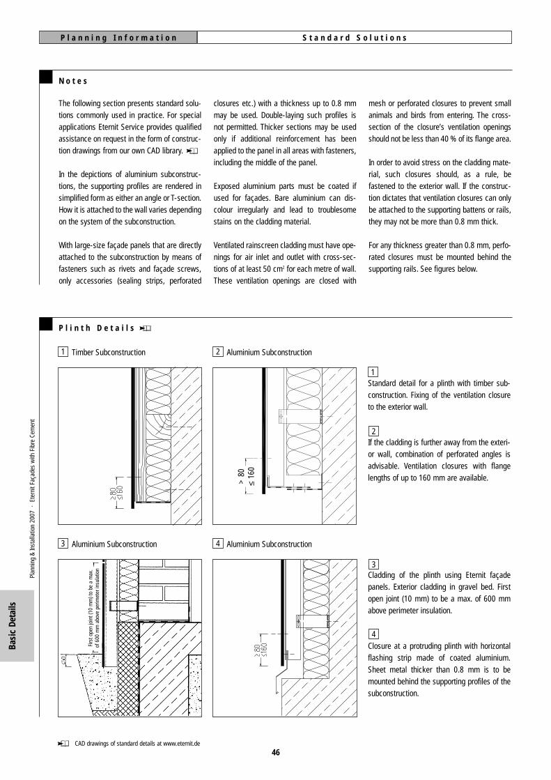
S t a n d a r d S o l u t i o n sP l a n n i n g I n f o r m a t i o n
N o t e s
P l i n t h D e t a i l s
The following section presents standard solu-tions commonly used in practice. For specialapplications Eternit Service provides qualifiedassistance on request in the form of construc-tion drawings from our own CAD library.
In the depictions of aluminium subconstruc-tions, the supporting profiles are rendered insimplified form as either an angle or T-section.How it is attached to the wall varies dependingon the system of the subconstruction.
With large-size façade panels that are directlyattached to the subconstruction by means offasteners such as rivets and façade screws,only accessories (sealing strips, perforated
closures etc.) with a thickness up to 0.8 mmmay be used. Double-laying such profiles isnot permitted. Thicker sections may be usedonly if additional reinforcement has beenapplied to the panel in all areas with fasteners,including the middle of the panel.
Exposed aluminium parts must be coated ifused for façades. Bare aluminium can dis-colour irregularly and lead to troublesomestains on the cladding material.
Ventilated rainscreen cladding must have ope-nings for air inlet and outlet with cross-sec-tions of at least 50 cm2 for each metre of wall.These ventilation openings are closed with
mesh or perforated closures to prevent smallanimals and birds from entering. The cross-section of the closure’s ventilation openingsshould not be less than 40 % of its flange area.
In order to avoid stress on the cladding mate-rial, such closures should, as a rule, befastened to the exterior wall. If the construc-tion dictates that ventilation closures can onlybe attached to the supporting battens or rails,they may not be more than 0.8 mm thick.
For any thickness greater than 0.8 mm, perfo-rated closures must be mounted behind thesupporting rails. See figures below.
Standard detail for a plinth with timber sub-construction. Fixing of the ventilation closureto the exterior wall.
If the cladding is further away from the exteri-or wall, combination of perforated angles isadvisable. Ventilation closures with flangelengths of up to 160 mm are available.
Cladding of the plinth using Eternit façadepanels. Exterior cladding in gravel bed. Firstopen joint (10 mm) to be a max. of 600 mmabove perimeter insulation.
Closure at a protruding plinth with horizontalflashing strip made of coated aluminium.Sheet metal thicker than 0.8 mm is to bemounted behind the supporting profiles of thesubconstruction.
Timber Subconstruction
Aluminium Subconstruction
Aluminium Subconstruction
Aluminium Subconstruction
CAD drawings of standard details at www.eternit.de
> 8
0≤
160
46
1 2
3
1
2
3
4
4
Plan
ning
&In
stal
latio
n 20
07 ·
Ete
rnit
Faça
des
with
Fib
re C
emen
t
Firs
t ope
n jo
int (
10 m
m) t
o be
a m
ax.
of 6
00 m
m a
bove
per
imet
er in
sula
tion
Basi
c De
tails

S t a n d a r d S o l u t i o n sP l a n n i n g I n f o r m a t i o n
W i n d o w S i l l D e t a i l s
H e a d e r D e t a i l s
NoteTo avoid disturbance by the sound of rain-drops, it is advisable that large sheet-metalsurfaces such as windowsills and flashing beinstalled with sound-deadening materialunderneath.
The window drip must be at least 20 mmbeyond the building components below it. Ifcopper is used, this distance must be at least50 mm. Depending on the height of the buil-ding, the apron must cover the façade panelfor:– up to 8 m at least 50 mm,– 8 to 20 m at least 80 mm,– over 20 m at least 100 mm.
Aluminium Subconstruction
Timber Subconstruction Aluminium Subconstruction
Timber Subconstruction Aluminium Subconstruction
A lintel with integrated Venetian blinds andcut-away profiles. The amount by which theprofiles can be cut away must be decided inconsultation with the subconstruction produ-cer as part of the structural analysis.
Edging using perforated closures to permit airinflow. The closures can extend to adjoin thewindow frame. Depending on the location ofthe window. It may be necessary to insert lin-tel strips made of the cladding material.
Standard installation with strips of Structura orNatura and ventilation closures.
CAD drawings of standard details available at www.eternit.de
Standard detail with angled window sill of coa-ted aluminium bent up at the reveals. As arule, a gap of 10 mm between the claddingand the window sill provides adequate ventila-tion of the façade. If this gap is larger, suitableventilation closures should be used. At pointsexposed to wind-driven rain, additional spa-cing profiles can be installed for waterproo-fing.
47
As in the drawing at left but with profile forwaterproofing.
1
1
2
2
3
3
4
4
5
5
Plan
ning
&In
stal
latio
n 20
07 ·
Ete
rnit
Faça
des
with
Fib
re C
emen
t
Basi
c De
tails
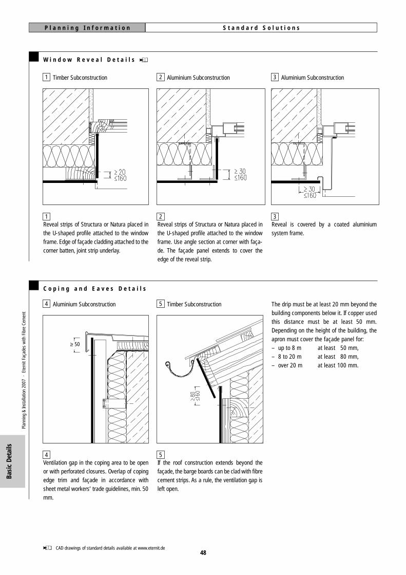
S t a n d a r d S o l u t i o n sP l a n n i n g I n f o r m a t i o n
W i n d o w R e v e a l D e t a i l s
Reveal is covered by a coated aluminiumsystem frame.
Reveal strips of Structura or Natura placed inthe U-shaped profile attached to the windowframe. Use angle section at corner with faça-de. The façade panel extends to cover theedge of the reveal strip.
Reveal strips of Structura or Natura placed inthe U-shaped profile attached to the windowframe. Edge of façade cladding attached to thecorner batten, joint strip underlay.
Timber Subconstruction Aluminium Subconstruction Aluminium Subconstruction
C o p i n g a n d E a v e s D e t a i l s
Ventilation gap in the coping area to be openor with perforated closures. Overlap of copingedge trim and façade in accordance withsheet metal workers’ trade guidelines, min. 50mm.
Aluminium Subconstruction Timber Subconstruction
If the roof construction extends beyond thefaçade, the barge boards can be clad with fibrecement strips. As a rule, the ventilation gap isleft open.
The drip must be at least 20 mm beyond thebuilding components below it. If copper usedthis distance must be at least 50 mm.Depending on the height of the building, theapron must cover the façade panel for:– up to 8 m at least 50 mm,– 8 to 20 m at least 80 mm,– over 20 m at least 100 mm.
≥ 50
48CAD drawings of standard details available at www.eternit.de
1
1
2
2
3
3
4
4
5
5
Plan
ning
&In
stal
latio
n 20
07 ·
Ete
rnit
Faça
des
with
Fib
re C
emen
t
Basi
c De
tails
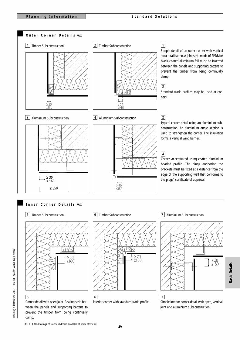
S t a n d a r d S o l u t i o n sP l a n n i n g I n f o r m a t i o n
O u t e r C o r n e r D e t a i l s
I n n e r C o r n e r D e t a i l s
Simple detail of an outer corner with verticalstructural batten. A joint strip made of EPDM orblack-coated aluminium foil must be insertedbetween the panels and supporting battens toprevent the timber from being continuallydamp.
Standard trade profiles may be used at cor-ners.
Typical corner detail using an aluminium sub-construction. An aluminium angle section isused to strengthen the corner. The insulationforms a vertical wind barrier.
Corner accentuated using coated aluminiumbeaded profile. The plugs anchoring thebrackets must be fixed at a distance from theedge of the supporting wall that conforms tothe plugs’ certificate of approval.
Timber Subconstruction
Timber Subconstruction Timber Subconstruction Aluminium Subconstruction
Timber Subconstruction
Aluminium Subconstruction Aluminium Subconstruction
Corner detail with open joint. Sealing strip bet-ween the panels and supporting battens toprevent the timber from being continuallydamp.
Interior corner with standard trade profile. Simple interior corner detail with open, verticaljoint and aluminium subconstruction.
≥ 30≤ 160
≤ 350
49CAD drawings of standard details available at www.eternit.de
1
3
2
4
1
2
3
4
5
5
6
6
7
7
Plan
ning
&In
stal
latio
n 20
07 ·
Ete
rnit
Faça
des
with
Fib
re C
emen
t
Basi
c De
tails

50
E t e r n i t S y s t e m s
W e a t h e r b o a r d
E t e r n i t - T e r g o
E t e r n i t - N a x o
pages 56-58
S t r u c t u r a l b o n d i n g
pages 59-61
pages 51-54
pages 55
A proven and elegant system of secret-fixedfaçades.
Fibre cement and stainless steel:materials in combination for creatively designed fixing.
Weatherboard: strongly modelled façades.
Concealed fixing using structural adhesives.
Terg
oNa
xoW
eath
erbo
ardi
ngRe
nova
tion
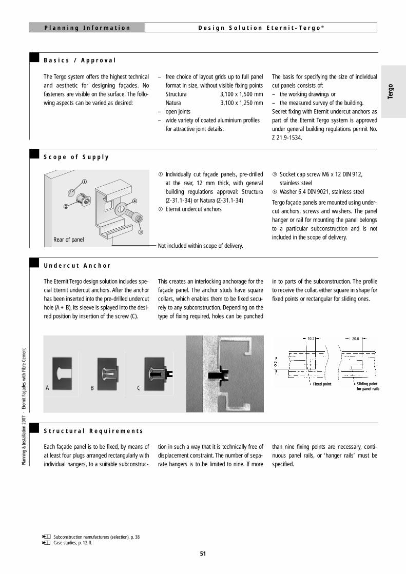
D e s i g n S o l u t i o n E t e r n i t - T e r g o ®P l a n n i n g I n f o r m a t i o n
51
B a s i c s / A p p r o v a l
The basis for specifying the size of individualcut panels consists of:– the working drawings or– the measured survey of the building.Secret fixing with Eternit undercut anchors aspart of the Eternit Tergo system is approvedunder general building regulations permit No.Z 21.9-1534.
3 Socket cap screw M6 x 12 DIN 912,stainless steel
4 Washer 6.4 DIN 9021, stainless steel
Tergo façade panels are mounted using under-cut anchors, screws and washers. The panelhanger or rail for mounting the panel belongsto a particular subconstruction and is notincluded in the scope of delivery.
S c o p e o f S u p p l y
– free choice of layout grids up to full panelformat in size, without visible fixing pointsStructura 3,100 x 1,500 mmNatura 3,100 x 1,250 mm
– open joints– wide variety of coated aluminium profiles
for attractive joint details.
1 Individually cut façade panels, pre-drilledat the rear, 12 mm thick, with generalbuilding regulations approval: Structura (Z-31.1-34) or Natura (Z-31.1-34)
2 Eternit undercut anchors
Not included within scope of delivery.
The Tergo system offers the highest technicaland aesthetic for designing façades. Nofasteners are visible on the surface. The follo-wing aspects can be varied as desired:
Subconstruction namufacturers (selection), p. 38Case studies, p. 12 ff.
1
24
3
Rear of panel
The Eternit Tergo design solution includes spe-cial Eternit undercut anchors. After the anchorhas been inserted into the pre-drilled undercuthole (A + B), its sleeve is splayed into the desi-red position by insertion of the screw (C).
in to parts of the subconstruction. The profileto receive the collar, either square in shape forfixed points or rectangular for sliding ones.
U n d e r c u t A n c h o r
Each façade panel is to be fixed, by means ofat least four plugs arranged rectangularly withindividual hangers, to a suitable subconstruc-
tion in such a way that it is technically free ofdisplacement constraint. The number of sepa-rate hangers is to be limited to nine. If more
than nine fixing points are necessary, conti-nuous panel rails, or ‘hanger rails’ must bespecified.
S t r u c t u r a l R e q u i r e m e n t s
Festpunkt Gleitpunkt
20.010.2
Sliding pointfor panel rails
Fixed pointA B C
Plan
ning
&In
stal
latio
n 20
07 ·
Ete
rnit
Faça
des
with
Fib
re C
emen
t
This creates an interlocking anchorage for thefaçade panel. The anchor studs have squarecollars, which enables them to be fixed secu-rely to any subconstruction. Depending on thetype of fixing required, holes can be punched
Terg
o
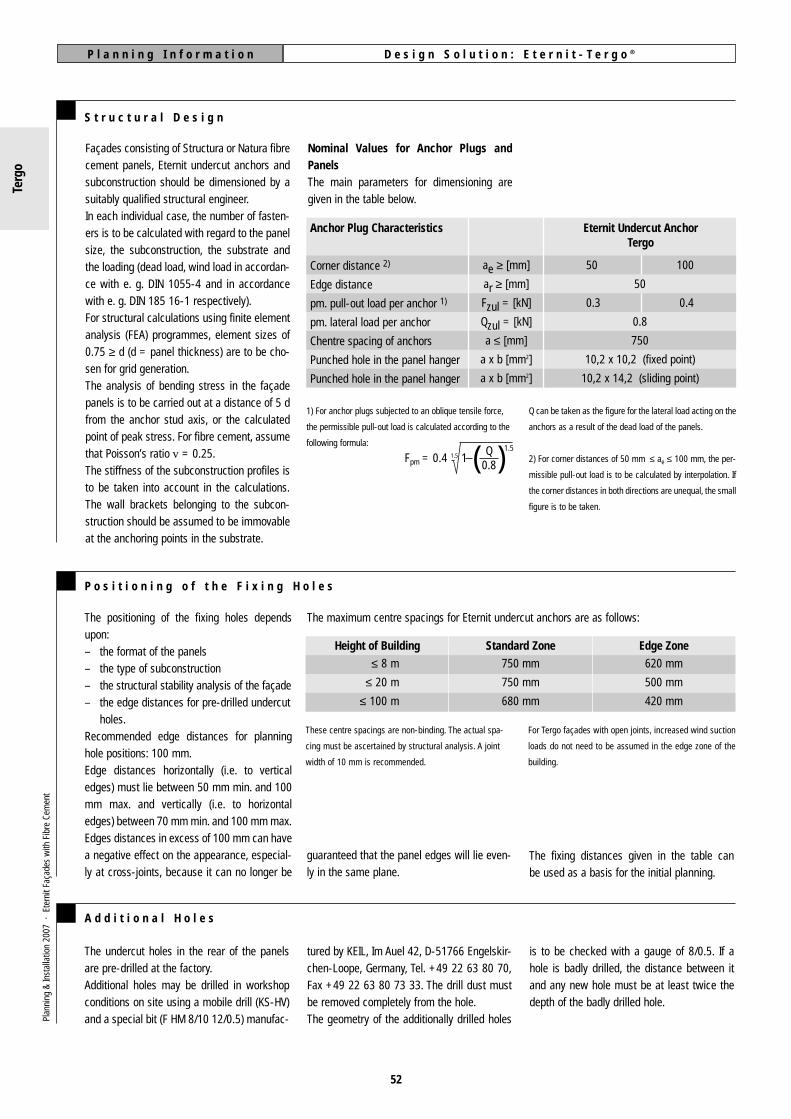
D e s i g n S o l u t i o n : E t e r n i t - T e r g o ®P l a n n i n g I n f o r m a t i o n
52
S t r u c t u r a l D e s i g n
1) For anchor plugs subjected to an oblique tensile force,
the permissible pull-out load is calculated according to the
following formula:
Fpm = 0.4 1.5 1
Q can be taken as the figure for the lateral load acting on the
anchors as a result of the dead load of the panels.
2) For corner distances of 50 mm ≤ ae ≤ 100 mm, the per-
missible pull-out load is to be calculated by interpolation. If
the corner distances in both directions are unequal, the small
figure is to be taken.
( )
Façades consisting of Structura or Natura fibrecement panels, Eternit undercut anchors andsubconstruction should be dimensioned by asuitably qualified structural engineer.In each individual case, the number of fasten-ers is to be calculated with regard to the panelsize, the subconstruction, the substrate andthe loading (dead load, wind load in accordan-ce with e. g. DIN 1055-4 and in accordancewith e. g. DIN 185 16-1 respectively).For structural calculations using finite elementanalysis (FEA) programmes, element sizes of0.75 ≥ d (d = panel thickness) are to be cho-sen for grid generation.The analysis of bending stress in the façadepanels is to be carried out at a distance of 5 dfrom the anchor stud axis, or the calculatedpoint of peak stress. For fibre cement, assumethat Poisson’s ratio v = 0.25.The stiffness of the subconstruction profiles isto be taken into account in the calculations.The wall brackets belonging to the subcon-struction should be assumed to be immovableat the anchoring points in the substrate.
Nominal Values for Anchor Plugs andPanelsThe main parameters for dimensioning aregiven in the table below.
Anchor Plug Characteristics
Corner distance 2)
Edge distance
pm. pull-out load per anchor 1)
pm. lateral load per anchor
Chentre spacing of anchors
Punched hole in the panel hanger
Punched hole in the panel hanger
Eternit Undercut AnchorTergo
ae ≥ [mm]
ar ≥ [mm]
Fzul = [kN]
Qzul = [kN]
a ≤ [mm]
a x b [mm2]
a x b [mm2]
50 100
50
0.3 0.4
0.8
750
10,2 x 10,2 (fixed point)
10,2 x 14,2 (sliding point)
Q0.8
1.5
The positioning of the fixing holes dependsupon:– the format of the panels– the type of subconstruction– the structural stability analysis of the façade– the edge distances for pre-drilled undercut
holes.Recommended edge distances for planninghole positions: 100 mm.Edge distances horizontally (i.e. to verticaledges) must lie between 50 mm min. and 100mm max. and vertically (i.e. to horizontaledges) between 70 mm min. and 100 mm max.Edges distances in excess of 100 mm can havea negative effect on the appearance, especial-ly at cross-joints, because it can no longer be
The maximum centre spacings for Eternit undercut anchors are as follows:
P o s i t i o n i n g o f t h e F i x i n g H o l e s
These centre spacings are non-binding. The actual spa-
cing must be ascertained by structural analysis. A joint
width of 10 mm is recommended.
For Tergo façades with open joints, increased wind suction
loads do not need to be assumed in the edge zone of the
building.
Height of Building Standard Zone Edge Zone≤ 8 m
≤ 20 m
≤ 100 m
750 mm
750 mm
680 mm
620 mm
500 mm
420 mm
A d d i t i o n a l H o l e s
The undercut holes in the rear of the panelsare pre-drilled at the factory.Additional holes may be drilled in workshopconditions on site using a mobile drill (KS-HV)and a special bit (F HM 8/10 12/0.5) manufac-
tured by KEIL, Im Auel 42, D-51766 Engelskir-chen-Loope, Germany, Tel. +49 22 63 80 70,Fax +49 22 63 80 73 33. The drill dust mustbe removed completely from the hole.The geometry of the additionally drilled holes
is to be checked with a gauge of 8/0.5. If ahole is badly drilled, the distance between itand any new hole must be at least twice thedepth of the badly drilled hole.
Plan
ning
&In
stal
latio
n 20
07 ·
Ete
rnit
Faça
des
with
Fib
re C
emen
t
The fixing distances given in the table canbe used as a basis for the initial planning.
guaranteed that the panel edges will lie even-ly in the same plane.
Terg
o

D e s i g n S o l u t i o n : E t e r n i t - T e r g o ®P l a n n i n g I n f o r m a t i o n
53
S u b c o n s t r u c t i o n w i t h P a n e l H a n g e r s
S u b c o n s t r u c t i o n w i t h P a n e l R a i l s
S u p p l i e r s o f S u b c o n s t r u c t i o n S y s t e m s
Panel hanger systems are supplied by the fol-lowing German companies:– BWM, Leinfelden-Echterdingen, ATK 103– SYSTEA Fassaden- und Balkonsysteme,
Norderstedt, Typ UBE 25– NAUTH-Fassadentechnik GmbH, Gernsbach– Montaflex, Braunschweig, Clickpress 2300– WS Fassaden, Vechelde, AG4/Tergo
Panel rails are supplied by:– SYSTEA, Typ UBEKA– BWM, ATK 103V– WS Fassaden, UP 24/Tergo
Panel hangers suitable for the system are fixedto the rear of the panels with undercutanchors. After this has been done, the panelsare hung on the horizontal supporting profilesof the subconstruction, adjusted and securedfirmly and permanently against sideways slip-
page with screws and special angles. Thehorizontal profiles should be interruptedapproximately every 4 m in order to avoidunwanted differences in the width of jointsbetween the panels being caused by expansi-on of the aluminium.
The dead load is transferred via two adjustablefixings in all cases.The minimum thickness of the construction,measured from the face of the façade panel(12 mm thick) to the surface of the supportingwall, is 100 mm.
Panel rails are fixed to the rear of the panelwithout constraint, using Eternit undercutanchors. After the panels have been aligned,the resulting assembly is attached to the sup-
porting profiles of the subconstruction, acces-sed via the joints.The dead load is transferred via two fixings inall cases.
For subconstructions with panel rails, a lockwasher (6 DIN 7980-A2) must be inserted bet-ween the undercut anchor and the washer atsliding points. The lock washers are includedin the scope of delivery by the subconstructionsuppliers.
For addresses of subconstruction suppliers, see p. 38
Structura orNatura, 12 mm
Panelhanger
Eternitundercutanchor
ScrewM6 x 12 DIN 912
Washer 6,4DIN 9012
Eternit undercutanchor
min.100
Plan
ning
&In
stal
latio
n 20
07 ·
Ete
rnit
Faça
des
with
Fib
re C
emen
t Façadepanel
ALMG SI 0.5 F25Panel rail
ScrewM6 x 12DIN 912
Washer 6.4DIN 9012
Lockwasher 6DIN 7980
Terg
o
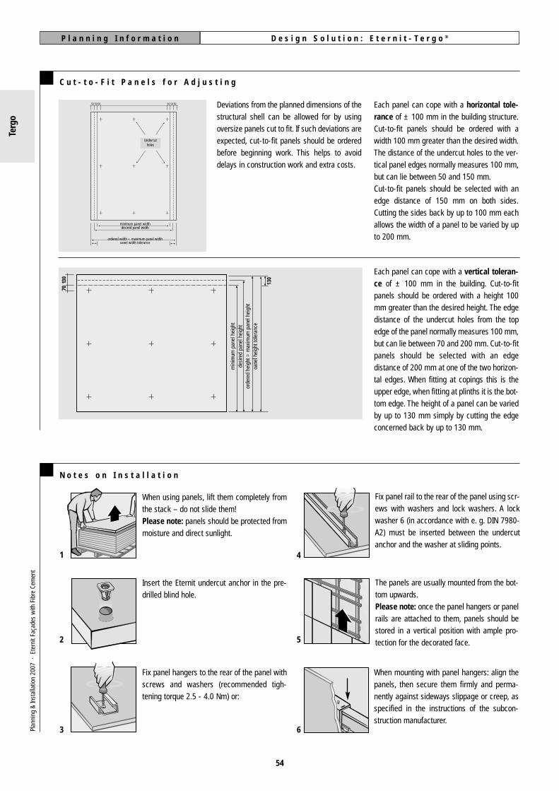
D e s i g n S o l u t i o n : E t e r n i t - T e r g o ®P l a n n i n g I n f o r m a t i o n
54
Each panel can cope with a horizontal tole-rance of ± 100 mm in the building structure.Cut-to-fit panels should be ordered with awidth 100 mm greater than the desired width.The distance of the undercut holes to the ver-tical panel edges normally measures 100 mm,but can lie between 50 and 150 mm.Cut-to-fit panels should be selected with anedge distance of 150 mm on both sides.Cutting the sides back by up to 100 mm eachallows the width of a panel to be varied by upto 200 mm.
C u t - t o - F i t P a n e l s f o r A d j u s t i n g
Deviations from the planned dimensions of thestructural shell can be allowed for by usingoversize panels cut to fit. If such deviations areexpected, cut-to-fit panels should be orderedbefore beginning work. This helps to avoiddelays in construction work and extra costs.
Each panel can cope with a vertical toleran-ce of ± 100 mm in the building. Cut-to-fitpanels should be ordered with a height 100mm greater than the desired height. The edgedistance of the undercut holes from the topedge of the panel normally measures 100 mm,but can lie between 70 and 200 mm. Cut-to-fitpanels should be selected with an edgedistance of 200 mm at one of the two horizon-tal edges. When fitting at copings this is theupper edge, when fitting at plinths it is the bot-tom edge. The height of a panel can be variedby up to 130 mm simply by cutting the edgeconcerned back by up to 130 mm.
50 50 50 50 50 50
Hinterschnitt-löcher
Minimale TafelbreiteSollmaß der Tafelbreite
Bestellte Breite = Maximale Tafelbreite
Toleranzbereiche Tafelbreite
7013
0
Min
imal
e Ta
felh
öhe
Sollm
aß d
er T
afel
höhe
Max
imal
e Ta
felh
öhe
Tole
ranz
bere
iche
Taf
elhö
he
130
When using panels, lift them completely fromthe stack – do not slide them!Please note: panels should be protected frommoisture and direct sunlight.
Insert the Eternit undercut anchor in the pre-drilled blind hole.
Fix panel hangers to the rear of the panel withscrews and washers (recommended tigh-tening torque 2.5 - 4.0 Nm) or:
N o t e s o n I n s t a l l a t i o n
Fix panel rail to the rear of the panel using scr-ews with washers and lock washers. A lockwasher 6 (in accordance with e. g. DIN 7980-A2) must be inserted between the undercutanchor and the washer at sliding points.
The panels are usually mounted from the bot-tom upwards.Please note: once the panel hangers or panelrails are attached to them, panels should bestored in a vertical position with ample pro-tection for the decorated face.
When mounting with panel hangers: align thepanels, then secure them firmly and perma-nently against sideways slippage or creep, asspecified in the instructions of the subcon-struction manufacturer.
1 4
2 5
3 6
Terg
o
Plan
ning
&In
stal
latio
n 20
07 ·
Ete
rnit
Faça
des
with
Fib
re C
emen
t
min
imum
pan
el h
eigh
tde
sire
d pa
nel h
eigh
tor
dere
d he
ight
= m
axim
um p
anel
hei
ght
oane
l hei
ght t
oler
ance
minimum panel widthdesired panel width
ordered width = maximum panel widthoanel width tolerance
Undercutholes

D e s i g n S o l u t i o n : E t e r n i t - N a x o ®P l a n n i n g I n f o r m a t i o n
55
M o u n t i n g o n a T i m b e r S u b c o n s t r u c t i o n 1
Eternit façade panels are fixed to a timber sub-construction with Naxo caps and stainlesssteel screws. The Naxo element is held inplace like a washer by the screw head. TheNaxo element can be used with a flat counter-sunk screw or a round head screw.
The vertical joint strips are continuous, whe-reas the horizontal ones are cut to the width ofthe panels. They are fixed to the battens forreasons of stability.
At vertical joints, two battens should be provi-ded for screwing the Naxo elements and onebatten for attaching the Naxo sealing strip.
The panels are pre-drilled for screwing at Ø 6mm. 2
Edge distances of 100 mm vertically and 100mm horizontally bring out the best in the sym-metrical, refined appearance of Naxo elementson Eternit façade panels.
In this variant, the horizontal joints are leftopen. Only the vertical joints are closed. This isdone with an L-shaped section, which can beof aluminium or stainless steel, as preferred. Ifstainless steel is used, the different coeffi-cients of expansion must be allowed for bymaking slots.
The panels are pre-drilled for riveting at � 9.5mm. 3
– Fixing with special rivets– Riveting jig– Naxo element for Al subconstruction
M o u n t i n g o n a n A l u m i n i u m S u b c o n s t r u c t i o n 1
1 Case study, pp 14-15
2 Mounting on a timber subconstruction, p. 31 ff.3 Mounting on an aluminium subconstruction, p. 37 ff.
Verticaljoint profile
Naxo conicalelement Ø 34/13 mm,with special rivet
Eternitfaçade panel,8 mm
Vertical supportingprofile
Wall bracket
Naxo conical elementØ 34/13 mmwith specialpan-head screw5.5/60 mm
Horizontalbatten24/48 mm
Naxo sealing strip70/0.8 mm
Eternitfaçade panel8 mm
Verticalsupportingbatten48/60 mm
Verticalbatten48/60 mm
100 mm
Fixing distances are not shown to scale
100 mm
Plan
ning
&In
stal
latio
n 20
07 ·
Ete
rnit
Faça
des
with
Fib
re C
emen
t
Naxo

W e a t h e r b o a r d i n gP l a n n i n g I n f o r m a t i o n
56
D e s i g n
The formats of the weatherboarding panelscan be chosen freely depending on the type offixing.
Eternit weatherboarding can be designed in amultitude of ways, taking the following aspec-ts into account:– panel layout – surface structure– format – fixing type– colour – joint formation– material – form
For weatherboarding, panel strips made oflarge-size façade panels are cut according toindividual specifications, either from Structuraor Natura fibre cement panels, or fromDuripanel Structura cement-bonded particleboards (wood cement).
Object examples pages 16-17
M i n i m u m E d g e D i s t a n c e o f F i x i n g H o l e s
horizontal edgedistance
vertical edgedistance
Structura / Natura
vertical supportingmember
horizontalsupportingmember
Wood
Aluminium
Wood
Aluminium
not visible
visible
20 mm
30 mm
80 mm
80 mm
50 mm from the top
45 mm from the bottom
horizontal edge distance
horizontal edge distance
vertical edgedistance(top)concealed
fixing
vertical edgedistance(bottom)
visible fixing
A l u m i n i u m S u b c o n s t r u c t i o n
be used. The butt joints of the horizontal sup-porting profiles may not lie between the fixingpoints of a panel. The butt joints of the verticalsupporting profiles must be at the sameheight.
enlarged to diameter Ø 9.5 (Eternit special bitfor fibre cement Ø 9.5 mm). The panels mustbe fixed without displacement constraint withtwo fixed points (fixed point sleeves) and therest sliding. In cases where the panels do notlie directly on the substrate, a riveting jig must
The weatherboarding can be mounted onstandard aluminium subconstruction. The sup-porting members can be aligned vertically orhorizontally. To mount the weatherboardingwithout displacement constraint, the pre-dril-led fixing holes in the façade panels must be
It is not necessary to seal the vertical joints.Backing them with a sealing strip improvesthe appearance. When working with overlyingpanels in a staggered arrangement, two rivetshave to be set in the middle of the upper partof the panel. One rivet is used for fixing, theother rivet is used as the point of support forthe panel lying over it.
≥ 3010
When mounting panels on horizontal suppor-ting profiles, the fixing holes must be at least80 mm from the vertical edge at panel buttjoints. The vertical joint can be sealed bybacking it with a sealing strip.
● Fixing point with fixed point sleeveSliding point
Offset panels with horizontal supportingprofiles
≥ 80
Weatherboarding on vertical AL subconstruction
Weatherboarding on horizontal AL subconstruction
45
Plan
ning
&In
stal
latio
n 20
07 ·
Ete
rnit
Faça
des
with
Fib
re C
emen
t
Wea
ther
boar
ding
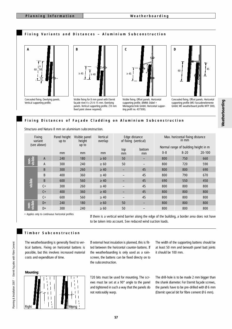
W e a t h e r b o a r d i n gP l a n n i n g I n f o r m a t i o n
57
F i x i n g V a r i a n t s a n d D i s t a n c e s – A l u m i n i u m S u b c o n s t r u c t i o n
A
Concealed fixing. Overlying panels.Vertical supporting profile.
B C D
Visible fixing for 8 mm panel with Eternitfaçade rivet 4 x 25 K-15 mm. Overlyingpanels. Vertical supporting profile. (10 mmfixed point sleeve required).
Visible fixing. Offset panels. Horizontalsupporting profile. (BWM; Dübel +Montagetechnik GmbH, Horizontal suppor-ting profil no. 437300).
Concealed fixing. Offset panels. Horizontalsupporting profile (WS FassadenelementeGmbH, WS weatherboard profile WTP 300).
≥50
10
60≥ 45 ≥ 40 ≥ 45
6045
F i x i n g D i s t a n c e s o f F a ç a d e C l a d d i n g o n A l u m i n i u m S u b c o n s t r u c t i o n
Fixingvariant
(see above)
Panel heightup to
Visible panelheightup to
Verticaloverlap
Edge distanceof fixing (vertical)
Max. horizontal fixing distancein mm
Normal range of building height in m
A
A
B
B
B
C+
C+
C+
D+
D+
240
300
300
400
600
300
400
600
240
300
180
240
260
360
560
260
360
560
180
240
≥ 60
≥ 60
≥ 40
≥ 40
≥ 40
≥ 40
≥ 40
≥ 40
≥ 60
≥ 60
50
50
–
–
–
–
–
–
50
50
–
–
45
45
45
45
45
45
–
–
800
800
800
800
690
800
800
800
800
800
750
720
800
790
550
800
800
800
800
800
660
590
690
670
450
800
800
800
800
800
mm mmbottom
mmtopmm 20-1008-200-8mm
Structura and Natura 8 mm on aluminium subconstruction.
+ Applies only to continuous horizontal profilesIf there is a vertical wind barrier along the edge of the building, a border area does not haveto be taken into account. See reduced wind suction loads.
non-
visi
ble
non-
visi
ble
visi
ble
The weatherboarding is generally fixed to ver-tical battens. Fixing on horizontal battens ispossible, but this involves increased materialcosts and expenditure of time.
Mounting:
Right Wrong
T i m b e r S u b c o n s t r u c t i o n
The width of the supporting battens should beat least 50 mm and beneath panel butt jointsit should be 100 mm.
The drill-hole is to be made 2 mm bigger thanthe shank diameter. For Eternit façade screws,the panels have to be pre-drilled with Ø 6 mm(Eternit special bit for fibre cement Ø 6 mm).
If external heat insulation is planned, this is fit-ted between the horizontal counter-battens. Ifthe weatherboarding is only used as a rain-screen, the battens can be fixed directy on tothe subconstruction.
T20 bits must be used for mounting. The scr-ews must be set at a 90° angle to the paneland tightened in such a way that the panels donot noticeably warp.
Plan
ning
&In
stal
latio
n 20
07 ·
Ete
rnit
Faça
des
with
Fib
re C
emen
t
Wea
ther
boar
ding

W e a t h e r b o a r d i n gP l a n n i n g I n f o r m a t i o n
58
F i x i n g V a r i a n t s a n d D i s t a n c e s – T i m b e r S u b c o n s t r u c t i o n
E F G
Concealed fixing.Overlying panels.
Concealed fixing.Offset panels.
Visible fixing.Overlying panels.
H
Visible fixing.Offset panels.
≥4540
≥6050
≥6050
1010≥ 45
30
50
Vertical joint formation, overlying panels
T i m b e r S u b c o n s t r u c t i o n
panels staggered in courses, two screws haveto be placed in the middle of the upper part ofthe panel. One screw is required for fixing, thesecond screw is used as a point of support forthe panel lying on top.
The width of the joint should be at least 8 mm.The supporting battens below the panel buttjoint must be protected from wetness with acontinuous sealing strip. With offset panels,the intermediate battens also have to be pro-tected with black sealing strip. When laying
≥ 20
≥ 15
10
+ Applies only to continuous horizontal profiles
* Observe the fire protection stipulations of the localbuilding regulations.
If there is a vertical wind barrier along the edge of the building, a border area does not haveto be taken into account. See reduced wind suction loads.
F i x i n g D i s t a n c e s f o r F a ç a d e C l a d d i n g o n a T i m b e r S u b c o n s t r u c t i o n
Fixingvariant
(see above)
Panel heightbis
Visible panelheightup to
Verticaloverlap
Edge distanceof fixing (vertical)
Max. horizontal fixing distancesin mm
Normal range of building height in m
E;F
E;F
G
G
G
H
H
H
240
300
300
400
600
300
400
600
180
240
260
360
560
260
360
560
≥ 60
≥ 60
≥ 40
≥ 40
≥ 40
≥ 40
≥ 40
≥ 40
50
50
–
–
–
–
–
–
–
–
45
45
45
45
45
45
800
800
800
800
600
800
800
800
730
570
800
780
490
800
800
680
640
410
680
670
420
800
800
540
mm mmBottom
mmTopmm 20-100*8-200-8mm
Structura and Natura 8 mm on timber subconstruction.
con-
ceal
edvi
sibl
e
Plan
ning
&In
stal
latio
n 20
07 ·
Ete
rnit
Faça
des
with
Fib
re C
emen
t
Wea
ther
boar
ding

S t r u c t r a l B o n d i n gP l a n n i n g I n f o r m a t i o n
59
A p p l i c a t i o n s / A p p r o v a l
The german general building regulationsapproval Z-36.4-58 for fixing Eternit fibrecement cladding panels to an aluminium sub-construction using the SikaTack panel adhesi-ve system allows the following design options:■ Free choise of formats up to max. 3,100
mm x 1,500 mm for Structura, max 3,100 x 1,250 mm for Natura.
■ Panels with a thickness of 8 mm can be bonded.
■ The adhesive bond forms a structuralconnection, so no additional fixings arenecessary.
■ The closed façade system (panel + adhesi-ve + subconstruction), in its assembledstate, fulfils the requirement of fire resi-stance (building material class in accor-dance with e. g. DIN 4102-B1).
R e q u i r e m e n t s
For the installation to quality as approved, itmust be carried out by certified fitters.Approval has only been granted for panels tobe mounted on a vertical (plumb) aluminiumsubconstruction designed for ventilated clad-ding.
Adhesive connection:■ adhesive bead to be set at 12 mm■ adhesive bead to run for full panel length■ permissible tensile strength 0.20 N/mm2
■ permissible shear strength 0.15 N/mm2
■ permissible shear deformation 1 mm
The deflection of any cladding panel may notexceed 1/100 of the span of the fibre cementpanel between supports plus the cantilever, ifthere is one.
A s s e m b l y
S u p p l i e r
Site work may only be carried out when thefollowing climatic conditions are given:■ assembly temperature +5°C to +35°C
(also applies for five hours after assembly).■ relative humidity ≤ 75 %.■ material temperature ≥ 3°C above tempe-
rature of dew point.■ assembly environment protected against
weather and dust.
For detailed assembly instructions, informationon the certification, and to order the “SikaTackPanel” system, contact the exclusive Sika dea-ler:
Walter Hallschmid GmbH & Co. KGWiesenstrasse 1D-94424 Arnstorf, GermanyTelephone +49 87 23 / 96 121Fax +49 87 23 / 96 127E-Mail: [email protected]
In preparing the supporting profile and theback of the panel, the following sequence ofsteps and times must be complied with exac-tly, in order to ensure reliable fixing.■ preparatory grinding,■ cleaning (Sika-Cleaner),■ airing (at least 10 minutes),■ application of adhesive primer
(Sika-Primer) and■ airing (at least 30 minuntes, at most 8 h)
The façade panels are to be fixed to the alumi-nium subconstruction in the following manner:■ apply the Sika fixing tape to the supporting
profile.
■ apply the Sika adhesive in the form of a defined, triangular-section bead (width > 8mm, height > 10 mm, (exposure to air:max. 10 minutes).
■ remove the protective film from the Sika fixing tape.
Do not press the panel on to the fixing tapeuntil the cladding panel has been positionedexactly.Any unwanted adhesive left on the aluminiumprofile must be removed immediately usingSika cleaning agent, as it can only be removedmechanically if left until later.
Plan
ning
&In
stal
latio
n 20
07 ·
Ete
rnit
Faça
des
with
Fib
re C
emen
t
Layi
ng

S t r u c t u r a l B o n d i n gP l a n n i n g I n f o r m a t i o n
60
F i x i n g T a b l e
F i x i n g S p e c i f i c a t i o n s
Thickness 8 mm
Panel width
in mm3,100
3,000
2,800
2,500
2,000
1,500
1,250
1,220
a =
a =
a =
a =
a =
a =
a =
a =
4 x 760
4 x 735
4 x 685
3 x 813
3 x 647
2 x 720
2 x 595
2 x 580
4 x 760
4 x 735
4 x 685
3 x 813
3 x 647
2 x 720
2 x 595
2 x 580
5 x 608
4 x 735
4 x 685
4 x 610
3 x 647
3 x 480
2 x 595
2 x 580
5 x 608
4 x 735
4 x 685
4 x 610
3 x 647
3 x 480
2 x 595
2 x 580
5 x 608
5 x 588
5 x 548
4 x 610
4 x 485
3 x 480
3 x 397
3 x 387
6 x 507
6 x 490
6 x 457
5 x 488
4 x 485
3 x 480
3 x 397
3 x 387
Supportingspacing
horizontallyin mm ≤ 8 m 8 to 20 m 20 to 100* m ≤ 8 m 8 to 20 m 20 to 100* m
Building height (standard zone) Building height (edge zone)+
a
+ Note: Reduced wind suction loads in accordance with e. g. DIN 18516-1.* Observe the maximum building height for the cladding system (German
building material class in accordance with e. g. DIN 4102-B1) in accordance with the local building
Plan
ning
&In
stal
latio
n 20
07 ·
Ete
rnit
Faça
des
with
Fib
re C
emen
t
Aluminium supportingprofile
Aluminium supportingmember
Eternit fibre cementfaçade panel(12 mm or 8 mm)
Adhesive primer
Assembly tape
Adhesive(thickness ≥ 3 mm)
Adhesive primer
Assembly tape
Adhesive
Layi
ng
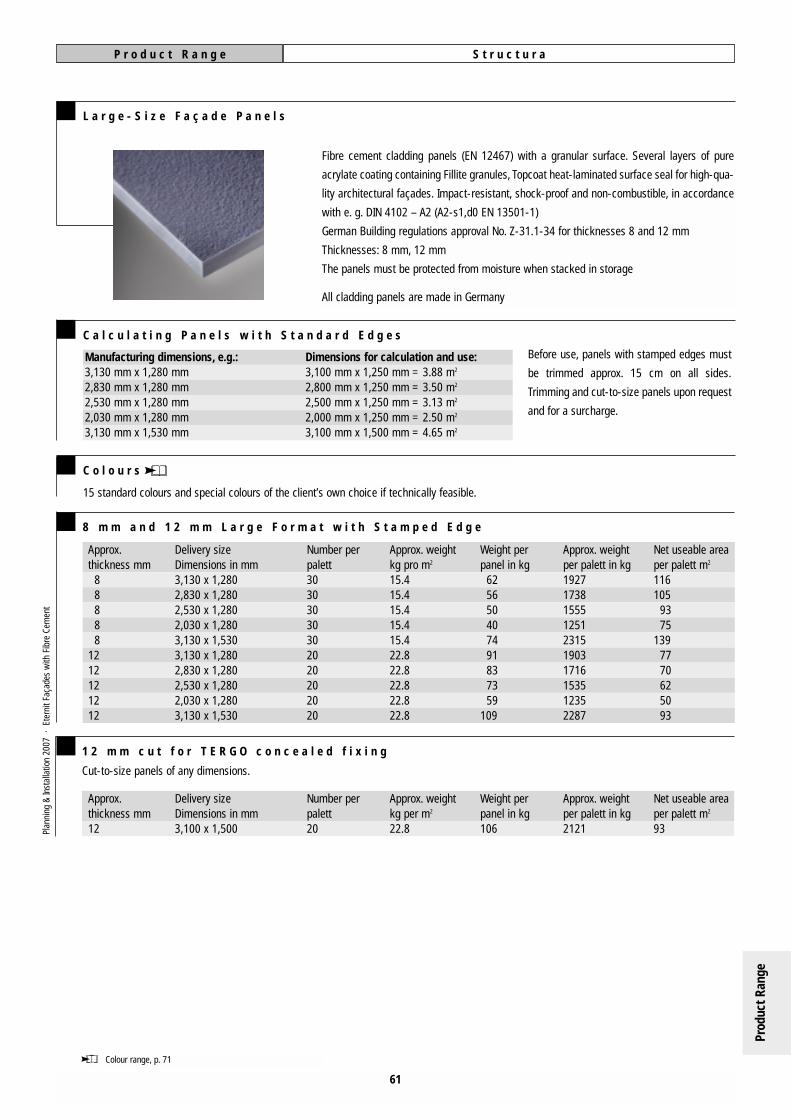
S t r u c t u r aP r o d u c t R a n g e
61
L a r g e - S i z e F a ç a d e P a n e l s
C a l c u l a t i n g P a n e l s w i t h S t a n d a r d E d g e s
Manufacturing dimensions, e.g.:3,130 mm x 1,280 mm2,830 mm x 1,280 mm2,530 mm x 1,280 mm2,030 mm x 1,280 mm3,130 mm x 1,530 mm
Dimensions for calculation and use:3,100 mm x 1,250 mm = 3.88 m2
2,800 mm x 1,250 mm = 3.50 m2
2,500 mm x 1,250 mm = 3.13 m2
2,000 mm x 1,250 mm = 2.50 m2
3,100 mm x 1,500 mm = 4.65 m2
C o l o u r s
15 standard colours and special colours of the client’s own choice if technically feasible.
Before use, panels with stamped edges must
be trimmed approx. 15 cm on all sides.
Trimming and cut-to-size panels upon request
and for a surcharge.
Fibre cement cladding panels (EN 12467) with a granular surface. Several layers of pure
acrylate coating containing Fillite granules, Topcoat heat-laminated surface seal for high-qua-
lity architectural façades. Impact-resistant, shock-proof and non-combustible, in accordance
with e. g. DIN 4102 – A2 (A2-s1,d0 EN 13501-1)
German Building regulations approval No. Z-31.1-34 for thicknesses 8 and 12 mm
Thicknesses: 8 mm, 12 mm
The panels must be protected from moisture when stacked in storage
All cladding panels are made in Germany
8 m m a n d 1 2 m m L a r g e F o r m a t w i t h S t a m p e d E d g e
Cut-to-size panels of any dimensions.
1 2 m m c u t f o r T E R G O c o n c e a l e d f i x i n g
Approx.thickness mm12
Delivery sizeDimensions in mm3,100 x 1,500
Number perpalett20
Approx. weightkg per m2
22.8
Weight perpanel in kg106
Approx. weightper palett in kg2121
Net useable areaper palett m2
93
Approx.thickness mm
88888
1212121212
Delivery sizeDimensions in mm3,130 x 1,2802,830 x 1,2802,530 x 1,2802,030 x 1,2803,130 x 1,5303,130 x 1,2802,830 x 1,2802,530 x 1,2802,030 x 1,2803,130 x 1,530
Number per palett30303030302020202020
Approx. weightkg pro m2
15.415.415.415.415.422.822.822.822.822.8
Weight perpanel in kg
625650407491837359
109
Approx. weightper palett in kg1927173815551251231519031716153512352287
Net useable area per palett m2
116105
9375
1397770625093
Colour range, p. 71
Plan
ning
&In
stal
latio
n 20
07 ·
Ete
rnit
Faça
des
with
Fib
re C
emen
t
Prod
uct R
ange

62
L a r g e - S i z e F a ç a d e P a n e l s
C a l c u l a t i n g P a n e l s w i t h S t a m p e d E d g e s
Manufacturing dimensions, e.g.:3,130 mm x 1,280 mm2,830 mm x 1,280 mm2,530 mm x 1,280 mm
Dimensions for calculation and use:3,100 mm x 1,250 mm = 3.88 m2
2,800 mm x 1,250 mm = 3.50 m2
2,500 mm x 1,250 mm = 3.13 m2
C o l o u r s
41 standard colours.
Afte trimming, the edges must be impregnated on site. Luko edge sealant is included in delivery.
Before use, panels with stamped edges must
be trimmed approx. 15 cm on all sides and
impregnated with Luko edge sealant at + 5° C
to + 25°C. Trimming and cut-to-size panels
with edge impregnation available upon
request and for a surcharge.
Air curend throughcoloured fibre cement façade panels acc. to EN 12467 with acrylate coa-
ting, coloured varnish, hot-film application. Impact-resistant, shock-proof and non-combu-
stible, in accordance with e. g. DIN 4102 – A2 (A2-s1,d0 EN 13501-1)
German Building regulations approval No. Z-31.1-34
Thicknesses: 8 mm, 12 mm
Colours: 2 colours with transparent surface coated on throughcoloured fibre cement façade
panels (anthracite, natural grey, ivory-colour). 9 colours with colour red vanish coated on
throughcoloured natural grey fibre cement sheets. 30 colours with coloured vanish coated on
throughcoloured anthracite fibre cement sheets
Irregularities, differences in shade and traces of the manufacturing process are to be
expected
The panels must be protected from moisture when stacked in storage
All cladding panels are made in Germany
8 m m a n d 1 2 m m L a r g e S i z e w i t h S t a m p e d E d g e
Cut-to-size panels of any dimemsions with edge impregnation.
1 2 m m C u t f o r T E R G O C o n c e a l e d F i x i n g
N a t u r aP r o d u c t R a n g e
Approx.thickness mm12
Delivery sizeDimensions in mmmax. 3,100 x 1,250
Number perpalett20
Approx. weightkg per m2
22.8
Weight perpanel kg83
Approx. weightper palett in kg2196
Net usable area per palett m2
73
Approx.thickness mm
888
121212
Delivery sizeDimensions in mm3,130 x 1,2802,830 x 1,2802,530 x 1,2803,130 x 1,2802,830 x 1,2802,530 x 1,280
Number per palett303030202020
Approx. weightkg per m2
15.415.415.422.822.822.8
Weight perpanel kg625650918374
Approx. weightper palett in kg192717381555190317161535
Net usable area per palett m2
116105
93777062
Colour range, p. 72
Plan
ning
&In
stal
latio
n 20
07 ·
Ete
rnit
Faça
des
with
Fib
re C
emen
t
Prod
uct R
ange
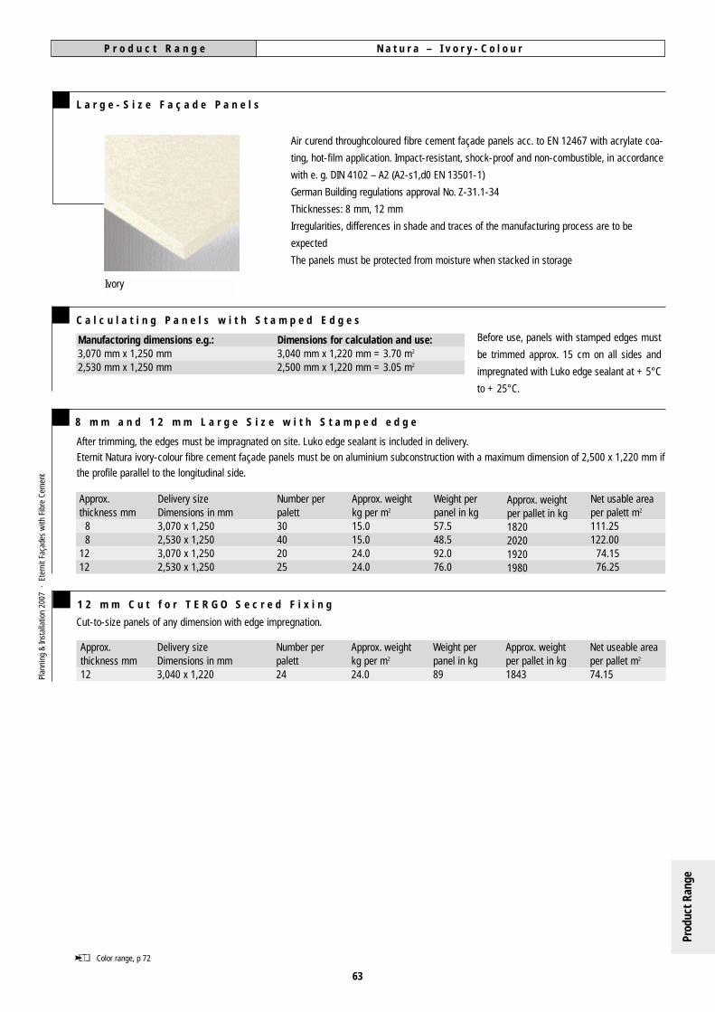
63
C a l c u l a t i n g P a n e l s w i t h S t a m p e d E d g e s
Manufactoring dimensions e.g.:3,070 mm x 1,250 mm2,530 mm x 1,250 mm
Dimensions for calculation and use:3,040 mm x 1,220 mm = 3.70 m2
2,500 mm x 1,220 mm = 3.05 m2
8 m m a n d 1 2 m m L a r g e S i z e w i t h S t a m p e d e d g e
Before use, panels with stamped edges must
be trimmed approx. 15 cm on all sides and
impregnated with Luko edge sealant at + 5°C
to + 25°C.
Approx.thickness mm
88
1212
Delivery sizeDimensions in mm3,070 x 1,2502,530 x 1,2503,070 x 1,2502,530 x 1,250
Number perpalett30402025
Approx. weight kg per m2
15.015.024.024.0
Weight perpanel in kg57.548.592.076.0
Approx. weightper pallet in kg1820202019201980
Net usable areaper palett m2
111.25122.00
74.1576.25
L a r g e - S i z e F a ç a d e P a n e l s
Ivory
Cut-to-size panels of any dimension with edge impregnation.
1 2 m m C u t f o r T E R G O S e c r e d F i x i n g
Approx.thickness mm12
Delivery sizeDimensions in mm3,040 x 1,220
Number perpalett24
Approx. weightkg per m2
24.0
Weight perpanel in kg89
Approx. weightper pallet in kg1843
Net useable areaper pallet m2
74.15
Color range, p 72
After trimming, the edges must be impragnated on site. Luko edge sealant is included in delivery.
Eternit Natura ivory-colour fibre cement façade panels must be on aluminium subconstruction with a maximum dimension of 2,500 x 1,220 mm if
the profile parallel to the longitudinal side.
Plan
ning
&In
stal
latio
n 20
07 ·
Ete
rnit
Faça
des
with
Fib
re C
emen
tP r o d u c t R a n g e N a t u r a – I v o r y - C o l o u r
Air curend throughcoloured fibre cement façade panels acc. to EN 12467 with acrylate coa-
ting, hot-film application. Impact-resistant, shock-proof and non-combustible, in accordance
with e. g. DIN 4102 – A2 (A2-s1,d0 EN 13501-1)
German Building regulations approval No. Z-31.1-34
Thicknesses: 8 mm, 12 mm
Irregularities, differences in shade and traces of the manufacturing process are to be
expected
The panels must be protected from moisture when stacked in storage
Prod
uct R
ange
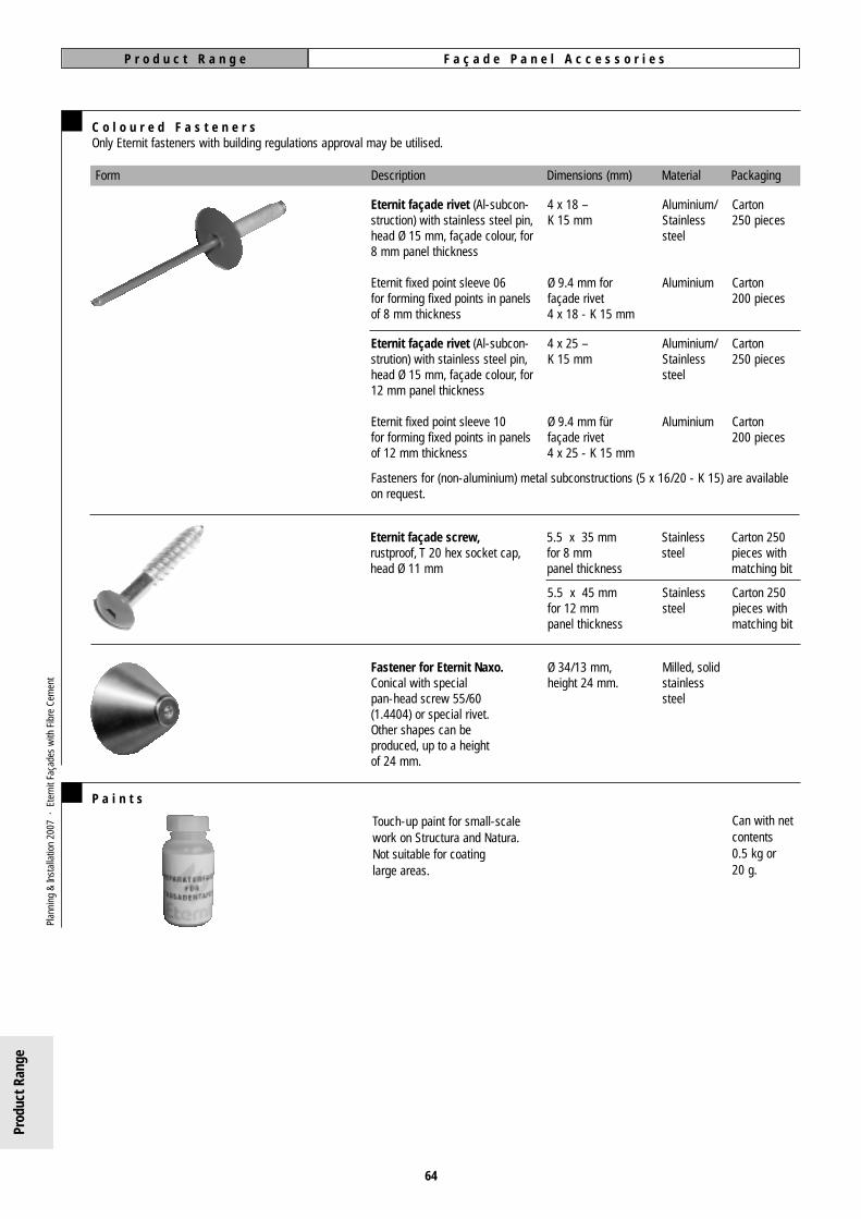
F a ç a d e P a n e l A c c e s s o r i e sP r o d u c t R a n g e
Form Description Dimensions (mm) Material Packaging
64
C o l o u r e d F a s t e n e r sOnly Eternit fasteners with building regulations approval may be utilised.
Eternit façade rivet (Al-subcon-struction) with stainless steel pin,head Ø 15 mm, façade colour, for8 mm panel thickness
Eternit fixed point sleeve 06for forming fixed points in panelsof 8 mm thickness
Eternit façade screw,rustproof, T 20 hex socket cap,head Ø 11 mm
4 x 18 – K 15 mm
Ø 9.4 mm forfaçade rivet4 x 18 - K 15 mm
5.5 x 35 mmfor 8 mmpanel thickness
5.5 x 45 mmfor 12 mmpanel thickness
Ø 34/13 mm,height 24 mm.
Aluminium/Stainlesssteel
Aluminium
Stainlesssteel
Stainlesssteel
Milled, solidstainless steel
Carton 250 pieces
Carton200 pieces
Eternit façade rivet (Al-subcon-strution) with stainless steel pin,head Ø 15 mm, façade colour, for12 mm panel thickness
Eternit fixed point sleeve 10 for forming fixed points in panels of 12 mm thickness
4 x 25 – K 15 mm
Ø 9.4 mm fürfaçade rivet4 x 25 - K 15 mm
Aluminium/Stainlesssteel
Aluminium
Carton 250 pieces
Carton200 pieces
Carton 250 pieces withmatching bit
Carton 250 pieces withmatching bit
Fastener for Eternit Naxo.Conical with specialpan-head screw 55/60(1.4404) or special rivet.Other shapes can beproduced, up to a heightof 24 mm.
Fasteners for (non-aluminium) metal subconstructions (5 x 16/20 - K 15) are available on request.
Touch-up paint for small-scalework on Structura and Natura.Not suitable for coatinglarge areas.
P a i n t s
Can with netcontents 0.5 kg or 20 g.
Plan
ning
&In
stal
latio
n 20
07 ·
Ete
rnit
Faça
des
with
Fib
re C
emen
t
Prod
uct R
ange

F a ç d e P a n e l A c c e s s o r i e sP r o d u c t R a n g e
65
D r i l l B i t s a n d A c c e s s o r i e s
Form Description Dimensions Packaging
Eternit drill jig inc. Ø 4.1 mm 1 piece1 bit Ø 4.1 mm,1 pin spanner
For façade rivets 5 x 16/20 - K 15 of stainless steelEternit drill jig inc. Ø 5.1 mm 1 piece1 bit Ø 5.1 mm,1 pin spanner
Special bit for Ø 9.5 mm 1 piecedrilling fibre cement(on Al subconstruction)Quality: VHM
Special bit for Ø 6.0 mm 1 piecedrilling fibre cement(on timber subconstruction)Quality: VHM
For pre-drilling façade panelscleanly and accurately
For drilling concentric holes in aluminiumsubconstructions when using pre-drilledpanels
J o i n t S e a l i n g S t r i p s
E d g e I m p r e g n a t i o n f o r N a t u r a a f t e r C u t t i n g t o S i z e
for anytimber subconstruction
Sealing strip, black
Sealing strip, black
Width 110 mm
Width 70 mm
Aluminium
Aluminium
25 m roll
25 m roll
Form Description Dimensions Material Packaging
only forlaying where not covered by panels
Sealing strip, black
Sealing strip, black
Width 110 mm
Width 70 mm
EPDM
EPDM
20 m roll
20 m roll
for the Eternit Naxodesign system
Sealing strip Width 70 mm Stainless steel,milled finish
20 m roll
After cutting on-site, apply Lukosealant to the cut edges of thepanels at temperatures between +5° to + 25° C. Coverage: approx.100 g per 100 metres of cut edgefor 8 mm thick panels.
Luko edge sealant for impregna-ting the exposed material at cutedges, with the necessary equip-ment. (Please refer to the informa-tion sheet!)
Pro applicator with 0.5 L canister of Luko
Plan
ning
&In
stal
latio
n 20
07 ·
Ete
rnit
Faça
des
with
Fib
re C
emen
t
Pro applicator with three special microfibre sponges andtray
20 Microfibre sponges
0.5 l in a can for panels cut on-site. Shake container wellbefore use, until the sediment has dissolved completely.Usable for 6 months after date of filling. Wait until foamhas subsided.
Prod
uct R
ange

66
Plan
ning
&In
stal
latio
n 20
07 ·
Ete
rnit
Faça
des
with
Fib
re C
emen
t
Order sheet 2006
Eternit Aktiengesellschaft · Sales Export · Knesebeckstraße 59-61 · D-10719 Berlin (Germany) · www.eternit.de · E-Mail: [email protected]: +49 (0) 39 34 85-202 · Fax +49 (0) 30 35 85-292
Telephone-Nr.:
Telephone-Nr.:
Country: *

Order sheet: through going drills and drills for secret fixing
Order sheet: cutted segments
Eternit Aktiengesellschaft · Sales Export · Knesebeckstraße 59-61 · D-10719 Berlin (Germany) · www.eternit.de · E-Mail: [email protected]: +49 (0) 39 34 85-202 · Fax +49 (0) 30 35 85-292
67
Plan
ning
&In
stal
latio
n 20
07 ·
Ete
rnit
Faça
des
with
Fib
re C
emen
t

C o n s t r u c t i o n P r i n c i p l e F a ç a d e s w i t h F i b r e C e m e n t
68
T h e C o n s t r u c t i o n P r i n c i p l e o f V e n t i l a t e d R a i n s c r e e n C l a d d i n g
A d v a n t a g e s
The Structura and Natura façade is construc-ted as ventilated rainscreen cladding, whichopens up a wide range of possibilities for desi-gning façades. Be it through colour, form, for-mat, joints or fixings, Structura and Naturapanels enable every façade to be given an
The value of ventilated façades clad in fibrecement panels has long been recognised inthe building industry. They offer a high degreeof technical and functional security. The waythey are constructed allows insulation of anythickness to be used, which is why they aresometimes referred to as ‘energy-saving faça-des’. The construction as a whole is open tomoisture diffusion. Its four components areconnected in such a way that the rainscreenand the insulation are kept completely separa-te from one another.■ Materials for cladding ventilated façades
are available in many forms, such as fullystained or colour coated fibre cement panels, and provide excellent weather-proofing.
■ The ventilation cavity (which must be atleast 20 mm) between the insulation andthe cladding allows air to flow upward, re-moving moisture and regulating the
amount of condensation taken up by thebuilding fabric.
■ Ventilation openings in the façade, withcross-sections of at least 50 cm2 permetre of wall guarantee the continuedsmooth functioning of the cladding system.
■ Insulation applied directly to the externalwall provides thermal insulation andsoundproofing mineral wool insulationhas the additional advantage of providingfire protection.
■ The subconstruction, of metal or timber, is the structural connection between thecladding and anchors in the supportingwall.
The system’s ability to cope with structuraltolerances and the fact that it can be installedin any weather are great advantages, especi-ally when renovating existing buildings.A long-term study of damage to buildings car-
ried out on behalf of the German Ministry ofConstruction has found that ventilated clad-ding systems have the least susceptibility todamage of any façade system.Single-skin wall structures, for instance, suffera significantly greater incidence of damagethan do double-skin structures with a cavity. Itis also becomming increasingly important thatindividual components can be completelyrecycled. In the case of ventilated claddingsystems, every constituent of the aluminium ortimber subconstruction, the thermal insulationand the cladding panels can be dismantledand processed separately for recycling.
identity of its own. In addition, ventilated rain-screen cladding is a highly effective systemowing to the fact that thermal insulation andweatherproofing are performed by differentparts of the system. This is achieved by thetechnical separation of the cladding panels
from the supporting structure and the thermalinsulation. As an economic, environmentallyfriendly, durable and comfortable solution,ventilated cladding systems are gaining inimportance, both for new buildings and forrefurbishment projects.
Ventilated cladding is especially long-livedand requires very little care and mainten-ance.The complete separation of the rainscreenfrom the insulation and supporting struc-ture projects the building from weathe-ring.The ventilation cavity prevents the build-up of heat and damage from moisture.Loadbearing exterior walls and, above all,the insulation are kept dry and fully func-tional, even with open horizontal joints.The insulation maximises the heat storagecapacity of the building fabric.The system as a whole is open to the dif-fusion of moisture.Insulation of any thickness can be usedwithout problems.The system as a whole is resistant to wea-thering and ageing. Using façade cladding
protects the building and increases itslifespan.Heat loss and cooling of the structure arehindered in winter, as is overheating insummer.A comfortable climate is created withinthe building.The building is shielded from strong varia-tions in temperature.A ventilated cladding system providessuperb soundproofing.Dimensional variations in the buildingfabric do not present a problem, since aventilated cladding system can absorbtolerances without compromising itsappearance.Damage can be repaired cheaply andeasily, without leaving lasting traces.Installation is not dependent on weatherconditions.
■
■
■
■
■
■
■
■
■
■
■
■
■
■
■
Plan
ning
&In
stal
latio
n 20
07 ·
Ete
rnit
Faça
des
with
Fib
re C
emen
t
Supportingwall
Fixing battens
Insulation
Ventilation
Fibre cementpanel

S e r v i c e F a ç a d e s w i t h F i b r e C e m e n t
69
E t e r n i t – Y o u r P a r t n e r f o r F a ç a d e s
P r o d u c t Q u a l i t y
How to contact us: Service line: +49 30 34 85 202Service fax: +40 30 3 85 292Our Project Service is already to answer yourcalls between 8 a.m. and 5 p.m.Fax form: p. 72
■ ■
■
E-mail: [email protected]
Internet: http://www.eternit.de
Ein Anruf genügt und unser Beratungsser-vice ist für Sie da. Ganz wie es sich für gutePartner versteht. Nutzen Sie unseren kom-petenten, schnellen und zuverlässigenObjektservice.
Design help, for example, using our CADdetails.
Assistance with costing and value mange-ment.
Assistance with technical and visual aspectsof the design, including CAD input.
Assistance with on-site coordination.
Documentation with product information andapplications, including suggested solutions.
Project Service: ■
■
■
■
■
■
■
Just give us a call – our team is ready andwaiting to help, just as things should be with agood buisiness partner. Take advantage of ourcompetent, quick and reliable advisory service.
Addresses of qualified façade installationfirms, so that the requirements of precisionand correct fabrication can be met.
We offer a wide range of design aids on thesubject of colour, such as colour charts andCAD design. Additionally, we would be pleasedto put you in contact with reputable colourdesigners.
Cladding Panels installed on Façades that areextremely exposed to the elements, e.g. inmaritime climates, may be prone to verdigris.We cannot guarantee that our products will be
completely proof against vandalism or otherextraordinary acts and influences. Individualproducts are guaranteed to function faultlesslyonly to the extent that they have been handled
in a workmanlike manner and in accordancewith current instructions on the same issuedby Eternit AG Germany.
Plan
ning
&In
stal
latio
n 20
07 ·
Ete
rnit
Faça
des
with
Fib
re C
emen
t
M o i s t u r e P r o t e c t i o n , t h e O p e n J o i n t i n V e n t i l a t e d R a i n s c r e e n C l a d d i n g
The design of ventilated rainscreen claddingprovides for an open joint where panels abut,in order to guarantee air circulation in thecavity behind the façade.A joint width of 10 mm between large-sizepanels creates an optimum aesthetic appea-rance of the façade, ensures perfect technicalperformance and facilitates construction.
Joints may not be constructed with a width of8 mm or less. Open joints should not beenconstructed with a width of greater than 12mm.If the horizontal joints are formed as openjoints, this considerably reduces the likelihoodof dirt spoiling the appearance of the façade.These also function as additional ventilation
openings, thus helping to ensure the smoothperformance of the cladding system.Detailed research by recognised testing agen-cies and practical experience have shown thatopen joints (8-10 mm) are sufficient for thefaçade to function as an open system (rain-screen).

Ete
rn
it Na
tur
a
70
Ca
se
Stu
dy
Planning & Installation 2007 · Eternit Façades with Fibre Cement
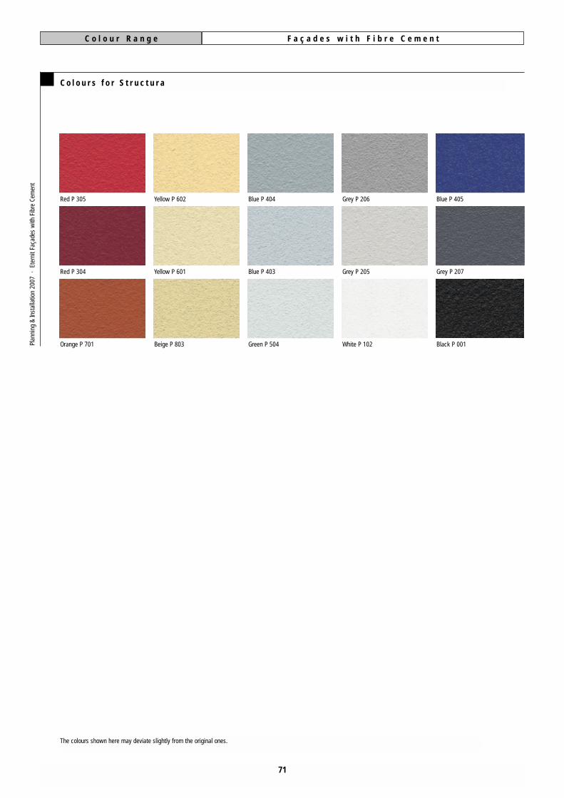
C o l o u r R a n g e F a ç a d e s w i t h F i b r e C e m e n t
71
C o l o u r s f o r S t r u c t u r a
Red P 305
Red P 304
Orange P 701
Yellow P 602
Yellow P 601
Beige P 803
Blue P 404
Blue P 403
Green P 504
Grey P 206
Grey P 205
White P 102
Blue P 405
Grey P 207
Black P 001
The colours shown here may deviate slightly from the original ones.
Plan
ning
&In
stal
latio
n 20
07 ·
Ete
rnit
Faça
des
with
Fib
re C
emen
t

C o l o u r R a n g e F a ç a d e s w i t h F i b r e C e m e n t
72
C o l o u r s f o r N a t u r a
The appearance of the fibre cement boardNatura is embossed to a large extent by natu-ral raw materials. Slightly irregularities, diffe-rent colouring and traces of the productionprocess are characteristically of these colou-red and transparency boards with their self-containted material identity. The colours arenot a full appearance of the samples and com-plete boards.Pl
anni
ng &
Inst
alla
tion
2007
· E
tern
it Fa
çade
s w
ith F
ibre
Cem
ent
coloured varnishon an anthracitethroughcolouredbasic board
transparent varnishon a throughcolou-red basic board
coloured varnishon a natural greythroughcolouredbasic board
grey N 291
grey N 292
grey N 293
blue N 491
beige N 891
beige N 892
green N 591
green N 592
white N 191
grey N 271
grey N 281
blue N 471
green N 581
green N 571
yellow N 671
yellow N 681
red N 371
brown N 971
black N 071
grey N 272
grey N 282
blue N 472
green N 582
green N 572
yellow N 672
yellow N 682
red N 372
brown N 972
black N 072
grey N 273
grey N 283
blue N 473
green N 583
green N 573
yellow N 673
yellow N 683
red N 373
brown N 973
black N 073
anthracite N 251
ivory N 854
natural grey N 250

Sender:
Company
Department
First name Surname
Street House number
Postcode Town/City Country
Telephone Fax
F a x L i n e + 4 9 3 0 3 4 8 5 2 9 2
I am planning the following project:
Please copy this form and fax it to:
Service Fax: +49 30 34 85 292
or send it in an envelope to the following address:
Eternit Aktiengesellschaft
Export
Knesebeckstrasse 59-61
D-10719 Berlin
Germany
Service Line Façade +49 30 34 85 202
and I require:
73
F a ç a d e s w i t h F i b r e C e m e n tF a x I n f o
Building type
Location
New building Renovation Extension
approx. m2 façade surface
approx. m2 balcony cladding
approx. start of construction
Eternit Building boards
Eternit Roofing material
Plan
ning
&In
stal
latio
n 20
07 ·
Ete
rnit
Faça
des
with
Fib
re C
emen
t
I am also interessted in:

Eternit Aktiengesellschaft · Sales export · Knesebeckstrasse 59-61 · D-10719 Berlin, Germany · www.eternit.de · export®eternit.de
ET 2
034-
1,5-
10.2
006
ABC.
Subj
ect t
o te
chni
cal c
hang
es.W
e ac
cept
no
liabi
lity
for p
rintin
g er
rors
and
col
our i
rreg
ular
ities
resu
lting
from
the
prin
ting
proc
ess.
R O O F I N G
C L A D D I N G
I N T E R I O R S
■ Roof and façade slates
■ Corrugated sheets
■ Roof membranes and roof
insulation systems
■ Large-size façade panels
■ Façade systems
■ Weatherboards
■ Balcony panels
■ Rendering Boards
■ Interior insulation panels and
reconstruction panels
■ Tilebacker Boards
an companyG R O U P
Related Documents