IAEA-TECDOC-865 Planning for environmental restoration of radioactively contaminated sites in central and eastern Europe Volume 3: Technologies for, and the implementation of, environmental restoration of contaminated sites Proceedings of a workshop held within the Technical Co-operation Project on Environmental Restoration in Central and Eastern Europe in Ret, Czech Republic, 12-16 December 1994 INTERNATIONAL ATOMIC ENERGY AGENCY

Welcome message from author
This document is posted to help you gain knowledge. Please leave a comment to let me know what you think about it! Share it to your friends and learn new things together.
Transcript
IAEA-TECDOC-865
Planning forenvironmental restoration of
radioactively contaminated sitesin central and eastern Europe
Volume 3:Technologies for, and the implementation of,
environmental restoration of contaminated sites
Proceedings of a workshop heldwithin the Technical Co-operation Project on
Environmental Restoration in Central and Eastern Europein Ret, Czech Republic, 12-16 December 1994
INTERNATIONAL ATOMIC ENERGY AGENCY
The IAEA does not normally maintain stocks of reports in this seriesHowever, microfiche copies of these reports can be obtained from
INIS ClearinghouseInternational Atomic Energy AgencyWagramerstrasse 5PO Box 100A 1400 Vienna, Austria
Orders should be accompanied by prepayment of Austrian Schillings 100,in the form of a cheque or in the form of IAEA microfiche service couponswhich may be ordered separately from the INIS Clearinghouse
The originating Section of this publication in the IAEA was:
Waste Technology SectionInternational Atomic Energy Agency
Wagramerstrasse 5P.O. Box 100
A-1400 Vienna, Austria
PLANNING FOR ENVIRONMENTAL RESTORATION OF RADIOACTIVELYCONTAMINATED SITES IN CENTRAL AND EASTERN EUROPE: VOLUME 3
TECHNOLOGIES FOR, AND THE IMPLEMENTATION OF,ENVIRONMENTAL RESTORATION OF CONTAMINATED SITES
IAEA, VIENNA, 1996iAEA-TECDOC-865ISSN 1011-4289
© IAEA, 1996
Printed by the IAEA in AustriaMay 1996
FOREWORD
The radioactive contaminant materials resulting from diverse activities in relation to thenuclear fuel cycle, defence related operations, and various industries in addition to medical andresearch facilities represent perhaps the most severe and immense pollution left from a past era. Thepolitical changes in central and eastern Europe (CEE) not only brought some disclosure of theradioactively contaminated sites, but also resulted in a political condition in which this region becamereceptive to co-operation from a range of outside countries.
It is under these circumstances that the IAEA decided to launch a Technical Co-operation(TC) Project on Environmental Restoration in Central and Eastern Europe. The project was initiatedin the latter part of 1992 and ended in 1994. The countries that were involved and represented in thisforum are: Belarus, Bulgaria, Croatia, Czech Republic, Estonia, Hungary, Kazakhastan, Poland,Romania, Russian Federation, Slovakia, Slovenia and the Ukraine. Several experts from countriesoutside the region participated and offered their co-operation throughout the project.
The TC regional project consisted of three workshops that addressed different, but sequential,themes. The basic criterion consisted in matching the structure of the IAEA project with a real-scaleenvironmental restoration project. The main focus was to identify radiological conditions in theregion and remediation plans, if any.
The subject of the first workshop held in Budapest, 4-8 October 1993, was the identificationand characterization of radioactively contaminated sites in the region. The second part of the projectand the second workshop (Piestany, Slovak Republic, 12-16 April 1994 ) involved planning andpreparing the identified sites for restoration. This included items such as the restoration objectives,dose and environmental assessment, cost analysis, strategy and prioritization. Eventually, the thirdpart of the project covered technologies for, and the implementation of, environmental restoration.The third and final workshop was held in Rez, Czech Republic, 12-16 December 1994.
A great deal of technical and scientific information which was formerly classified or onlyavailable confidentially was disclosed under the auspices of the project. Information available onlyin national languages (mainly Russian) was made available in English. The three volumes of thisTECDOC incorporate reports submitted by national experts and invited speakers at or following thethree workshops. Volume 1 includes papers describing the identification and characterization ofcontaminated sites in the region. It also presents the objectives of the project, illustrates past andcurrent IAEA activities on environmental restoration, provides a scientific framework for the projectand the individual workshops and summarizes the results achieved. Volume 2 includes the papersthat involve planning and preparing the sites for restoration. Volume 3 presents technologies for,and the implementation of, environmental restoration.
It should be noted that papers submitted by national experts are variable in length and content,as this reflects national conditions and approaches. Countries having one or two contaminated sitesconcentrate on technical details, countries with dozens of sites offer a general overview. Problemsassociated with contamination from the uranium mining and milling industry are intrinsically differentfrom those related to accident generated contamination. By means of the papers contained in thisTECDOC, the reader may get a general impression of the vastness of the problems in central andeastern Europe. The IAEA officer responsible for the workshops was M. Laraia, of the Division ofNuclear Fuel Cycle and Waste Management. Papers were compiled and edited by J. Wiley, of thesame Division.
The IAEA wishes to express its thanks to all participants in the programme and would liketo take this opportunity to acknowledge the excellent co-operation and hospitality of the institutionsthat hosted the project workshops.
EDITORIAL NOTE
In preparing this publication for press, staff of the IAEA have made up the pages from theoriginal manuscripts as submitted by the authors. The views expressed do not necessarily reflect thoseof the governments of the nominating Member States or of the nominating organizations.
Throughout the text names of Member States are retained as they were when the text wascompiled.
The use of particular designations of countries or territories does not imply any judgement bythe publisher, the IAEA, as to the legal status of such countries or territories, of their authorities andinstitutions or of the delimitation of their boundaries.
The mention of names of specific companies or products (whether or not indicated as registered)does not imply any intention to infringe proprietary rights, nor should it be construed as anendorsement or recommendation on the part of the IAEA.
The authors are responsible for having obtained the necessary permission for the IAEA toreproduce, translate or use material from sources already protected by copyrights.
CONTENTSTechnologies for and implementation of environmental restoration projects
[Background p a p e r ] . . . . . . . . . . . . . . . . . . . . . . . . . . . . . . . . . . . . . . . . . . . . . . . . . . 7M. Laraia
Technologies for restoration of environment contaminated with radionuclidesin Belarus . . . . . . . . . . . . . . . . . . . . . . . . . . . . . . . . . . . . . . . . . . . . . . . . . . . . . . . . . 37G. Sharovarov
Uranium industry in Bulgaria and environment: Technologies andimplementation of environmental restoration projects . . . . . . . . . . . . . . . . . . . . . . . 51M. Dimitrov, E.I. Vapirev, L. Minev, T. Boshkova
Technologies for and implementation of environmental restoration in Canada . . . . . . . . 59R. W. Pollock, D.G. Feasby
Restoration of radioactively contaminated sites in the Republic of Croatia . . . . . . . . . . . 87D. Subasic, A. Schaller, D. Barisit, S. LuM, B. VeM6, J. Kovat,N. Lokobauer, G. Marovit,
Technologies for and implementation of environmental restoration in theuranium industry in the Czech Republic . . . . . . . . . . . . . . . . . . . . . . . . . . . . . . . . . . 121P.Andel, V..Pfibdn
Remediation of Ecarpiere uranium tailing pond by COGEMA (France) . . . . . . . . . . . . . 139Ph. Crochon, J.L. Daroussin
Rehabilitation technologies to be used in the decommissioning of uraniummining sites in the Federal Republic of Germany . . . . . . . . . . . . . . . . . . . . . . . . . . . 153G. Lange
The restoration work on the Hungarian uranium mining area . . . . . . . . . . . . . . . . . . . . . 161L. Juhasz, Z. Lendvai, J. Csicsak, M Csovari
A project carried out in Italy to secure a site contaminated by Cs-137ofunknown origin . . . . . . . . . . . . . . . . . . . . . . . . . . . . . . . . . . . . . . . . . . . . . . . . . . 173C. Cochi, G. Mastino
Technology for restoration of contaminated sites; Review of availableexperience in the field of environmental restoration in Romania . . . . . . . . . . . . . . . 181P. Sandru
Technologies of environmental restoration in Russia . . . . . . . . . . . . . . . . . . . . . . . . . . . 189A.F. Nechaev, V. V. Projaev
Technologies for and implementation of environmental restoration projectin the Slovak Republic . . . . . . . . . . . . . . . . . . . . . . . . . . . . . . . . . . . . . . . . . . . . . . . 211O. Slavik, J. Moravek, M. Vladdr
Technologies for and implementation of environmental restoration projectsin Slovenia . . . . . . . . . . . . . . . . . . . . . . . . . . . . . . . . . . . . . . . . . . . . . . . . . . . . . . . . 225M.J. Krizman, Z. Logar
Technologies for and implementation of environmental restoration of theUranium Mine in Ranstad Sweden . . . . . . . . . . . . . . . . . . . . . . . . . . . . . . . . . . . . . . 237B. Sundblad, Y. Stiglund
Technologies for environmental restoration in Ukraine . . . . . . . . . . . . . . . . . . . . . . . . . 243C. Rudy, 0. Avdeev, Yu. Soroka, G. Perepeliatnikov, S. Saversky
Methods and techniques used to rehabilitate radioactively contaminated sitesin the United Kingdom . . . . . . . . . . . . . . . . . . . . . . . . . . . . . . . . . . . . . . . . . . . . . . . 281L.R. Fellingham, A.D. Moreton
Conclusion: Problems (encountered and foreseen) in relation to the project . . . . . . . . . . 289List of Participants . . . . . . . . . . . . . . . . . . . . . . . . . . . . . . . . . . . . . . . . . . . . . . . . . . . . . 291
Background Paper
TECHNOLOGIES FOR AND IMPLEMENTATION OFENVIRONMENTAL RESTORATION PROJECTS
3VL LaraiaWaste Management Section,International Atomic Energy Agency, Vienna
Abstract
A great deal of experience is available related to the cleanup of small and medium sized landareas. A variety of techniques and equipment are available for the cleanup of contaminatedareas and for the transportation and disposal of wastes arising from such cleanups. Theselection of methods and technical procedures for environmental restoration will be governedby criteria such as:
external dose rates and the mixture of radionuclides present;the nature of the location and of items requiring cleanup;mechanical properties of the materials requiring treatment;the availability of different methods of cleanup and the technical facilities for applyingthem;the availability of trained staff.
Although a great deal is known about such cleanups, further work is required, especially onthe decontamination of urban areas. Most of the information provided in this paper is basedon IAEA's Technical Report Series No. 300, Cleanup of Large Areas Contaminated as aResult of a Nuclear Accident, 1989.
1. INTRODUCTION
This paper represents the logical continuation of those presented at the Budapest and PiestanyWorkshops. It covers practical methods and techniques to decontaminate or rectify radioactivelycontaminated sites. As for previous project papers, the focus of this paper is on accident-contaminatedsites. For uranium mining and milling waste, such as mill tailings and mining debris, differentprocedures will normally apply for environmental restoration. However, relevant information on howto decontaminate/dispose of contaminated materials from uranium mines/mills can also be found inthis paper.
2. STABILIZATION OF CONTAMINATION
Following a serious nuclear accident which results in widespread contamination, the detrimentto man from the radioactive contaminants can be reduced by the decontamination methods describedbelow, by interdiction of the contaminated area or by using coatings to stabilize the contaminationusing the techniques described in this section.
The objective of using coatings to stabilize or immobilize radioactive contamination on soils,buildings, roads and equipment are to:
(a) Reduce the spread of contamination to clean areas.(b) Reduce the airborne inhalation hazards.(c) Decontaminate surfaces by incorporating the contamination in a removable coating.(d) Reduce the volume of radioactive waste generated. If the contamination is in an area which
does not contribute to radiation doses and it arises predominantly from relatively short livedradioisotopes, it may be desirable to stabilize and leave it to decay.

In most but not all cases, the application of surface stabilizers is a short term corrective actionwhich would be followed by further decontamination. For uranium mining and milling waste,stabilization is a basic part of the environmental restoration project. It may include dewatering thetailings, building/repairing dams, covering the tailings and neutralizing generated acids.
A large number of stabilizers/fixatives are commercially available and these are generallyclassified as chemical, mechanical, physical or chemical with mechanical characteristics. Thestabilizers are rated according to their:
preferred applicability to various land types and land use classeshazard leveldurabilityapplication methods, andeffect on vegetation recovery.
Chemical stabilizers are liquid or solid additives mat alter the physical properties of the treatedsurface.
Mechanical stabilizers are used to physically cover the contamination without modifying thephysical properties of the soil or surface. They include concrete and asphalt covers, manufacturedmaterials like polyvinyl films or erosion control nets, sandbags and rock rip-rap.
Physical stabilization of soils can be carried out by using heat, electricity or cold to changethe physical properties.
Another approach to stabilization is to combine it with shielding. For example, 5 cm ofconcrete would reduce the gamma radiation levels from 137Cs by a factor of about 3 and would fix thecontaminants. This could be a more cost effective solution for car parks or some roadways thanremoval and disposal of the contaminated surface, particularly if waste disposal sites are limited.
In urban areas, stabilization of contamination on areas which do not require decontaminationand which will not be subject to weathering could be considered. For example, vertical building wallsmay have lower contamination levels than roof surfaces and may not need to be decontaminated. Inthis case stabilization of the contaminants by a polymer spray, painting, etc., would reduceresuspension from the surface and should also reduce additional contamination when the roof surfacesare washed down.
3. DECONTAMINATION TECHNIQUES AND EQUIPMENT
Decontamination of materials, equipment, buildings and sites to permit operation, inspection,maintenance, modification or plant decommissioning to be done safely has been an integral part of thenuclear industry since its inception. A large number of decontamination techniques and a large varietyof chemical mixtures have been developed over the years to assist in removing contamination fromall kinds of surfaces and these are continually being improved. These techniques also include meansof decontaminating reasonably large areas of land which have been contaminated by mining/millingwastes, nuclear test fallout, etc.
To achieve a good decontamination factor (DF), a decontamination process must be selectedon the basis of site specific considerations taking into account a wide variety of parameters such as:
type of material: metal, asphalt, concrete, soil, wood, etc.type of surface: rough, porous, coated (paint, plastic, etc.)composition of contaminant: activation or fission products, actinides, etc.
chemical and physical form of contaminant: solubility, aerosol, flocculent particles, complexcompound with other materials, etc.; for many decontamination processes, the smaller theparticle, the more difficult it is to remove from a surfacethe decontamination factor requiredthe proven efficiency of the processthe method of deposition; the distribution of the decontamination and its adherence to thesurface can depend on whether the deposition was wet or dry.
Other factors which are important in selecting the method and equipment, but which do notaffect the DF are:
availability, cost and complexity of the decontamination equipmentthe need to condition the secondary waste generatedoccupational and public doses resulting from decontaminationother safety, environmental and social issuesavailability of trained staffthe amount of work involved and the difficulty in decontaminating the equipment used for thecleanup if it is to be reused.
In summary, the final decontamination process selected will depend on the best overall balancebetween the above factors to minimize the overall impact and net detriment to people using the mostcost effective means.
In the following sections, the methods available for decontaminating buildings, equipment,roadways and large land areas are described.
3.1. Decontamination of Buildings, Equipment and Paved Surfaces
Much of the past decontamination experience at nuclear facilities relates to the cleanup ofbuildings, equipment and paved surfaces in or adjacent to nuclear reactors and other facilities duringnormal operations or decommissioning.
However, there has been less attention to the development of methods suitable for large scaleapplication to urban areas and to urban construction materials following a nuclear accident. Many ofthe techniques suitable for nuclear plants and sites may be too expensive for application on the scalerequired in an urban environment Accessibility and recovery of the radioactive wastes generated bydecontamination procedures are also likely to present more difficult problems in an urban environment
Decontamination methods range from simple physical cleaning techniques, including allowancefor natural weathering, to fairly sophisticated physical and chemical procedures. Some of the methodsdescribed use industrial equipment such as road sweepers which are readily available in manyindustrialized countries and which can be operated by relatively unskilled personnel. In other casesspecialized techniques such as pavement grading and sand blasting require skilled personnel andspecial consideration of airborne contamination problems.
In an urban environment, there will be a large number of building designs, surface finishes,roof covers, a variety of outdoor equipment and many different paved surfaces. Building surfacefinishes can range over smooth tile, concrete, brick, wood and many other surfaces. Paved surfacescan be concrete or asphalt, and may be new, cracked, broken or porous. Outdoor equipment caninclude motor vehicles, power transformers, bicycles, etc.
The large range of buildings, surfaces and occupancy factors met in an urban environmentmeans that several cleanup criteria would be required since it would be much more difficult to cleancertain types of surfaces and in many cases it would not be necessary to clean to the same level. It
may be possible to leave relatively inaccessible areas contaminated, for example the tops and sides ofhigh buildings, provided that the contamination is fixed and does not affect those in the building. Thecleanup levels required for certain industrial sites having low occupancy and no routine public accesscould be less restricted than those for areas with heavy public usage, such as shopping centres, whichmay require very rigorous decontamination to reduce the collective dose equivalent and prevent thetransfer of radioactivity into buildings via footwear and clothing.
3.1.2. Motorized Sweeping and Vacuum Sweeping
In urban areas of industrialized countries, motorized road sweepers and vacuum sweepers areused for cleaning roads and parking areas; hence such equipment should be readily available. Vacuumsweeping is the more attractive procedure since it not only cleans the surface but also picks up thedisplaced contamination more effectively. However, the removal efficiency for small contaminatedparticles, typical of those from a reactor accident, is likely to be low for these types of equipment.
Although cleanup efficiencies might be low, it is good practice to remove dry loose particulatematerial using this process before applying a liquid cleaner which could fix the contamination or causeit to penetrate porous surfaces. Even if only marginal decontamination is achieved, the amount ofwaste produced is minimal because there are no added reagents. Therefore, it is recommended thatwhere access is possible, vacuum sweeping should be considered as the initial decontamination processfor buildings, equipment and paved surfaces.
Since many sweepers collect the particulate material in a container on the vehicle, the doseto the operator will increase unless the container is shielded and/or water filled (which prevents dustemission as well as providing shielding).
3.1.2. Firehosing
It seems likely that firehosing could be a potentially useful technique provided it can beapplied fairly promptly after an accident and depending on the particle size and texture of the surface.It relies on the contaminants still being in an accessible particulate or soluble form on the surface ofmaterials where it can be redissolved or resuspended into the runoff water created. Obviously, as timeelapses the likelihood of rainfall washing contamination further down into the matrix becomes greater.
The practicality of firehosing, and also high pressure water jetting, will depend upon theaccessibility of drainage routes. Most road surfaces are provided with adequate storm drainage routesand firehosing of roads as soon as possible after an accident would seem to be a desirable step.However, if the firehosing merely shifts contamination to areas where it can become adsorbed moreeasily, then it may actually have a detrimental effect. For instance, movement of contamination fromroofs or vertical surfaces of buildings to ground level could lead to a higher dose commitment.
Firehosing should also be useful for decontaminating buildings and equipment having smoothimpermeable surfaces. It will be less effective for permeable, porous, rusty or cracked surfaces. Thebig advantage of firehosing is that the equipment is readily available in most areas.
During firehosing, large volumes of contaminated water could be produced. Great care shouldbe taken to ensure that as far as practicable this water does not result in the contamination of drinkingwater supplies or of other areas. If the technique is used for widespread washing of buildings androads, containing the water will be a major task.
3.1.3. Aqueous Methods Incorporating Chemical Additives
Numerous proprietary solutions are available for decontaminating surfaces at ambienttemperature under non-aggressive conditions. Generally, these reagents contain various combinationsof detergents and complexing agents.
10
The effectiveness of washing procedures can be improved by the addition of various inorganicions (Na+, K+, Cs+, NH4
+) to exchange with adsorbed Cs+. It was found that a dilute solution ofammonium nitrate was effective in removing caesium, adsorbed on a number of common urbanconstruction materials. This reagent, as agricultural fertilizer, is readily available in large quantities,which is an important factor. Spraying with dilute ammonium nitrate solution always resulted in thedisplacement of some caesium; in some cases as much as 90% of the caesium was displaced in lessthan three hours. In general, aged weathered materials were most amenable to decontamination withammonium nitrate. This technique has so far only been applied on a laboratory scale. Furtherdevelopment is needed for full scale application for extended periods, for the collection and disposalof the radioactive waste arisings, and for very large scale use, consideration of the possiblecontamination of groundwater supplies.
3.1.4. Abrasive Jet Cleaning
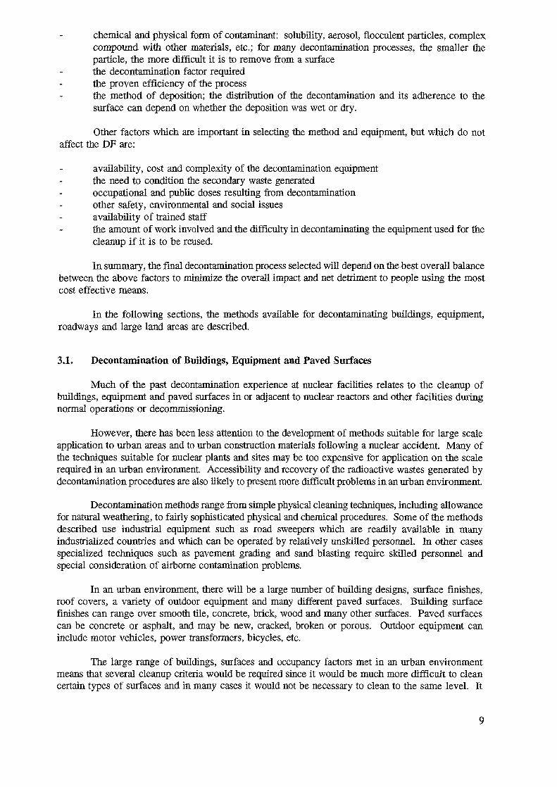
Abrasive jet cleaning including both wet and dry procedures with various types of grit hasbeen employed on a large number of occasions in the nuclear industry. These applications range fromheavily contaminated pipework with the contamination fixed in oxide on the surface, to lightlycontaminated surfaces. Typical abrasive which have been used include sand, glass beads, metallicbeads and soft materials such as nut shells and rice hulls. Abrasive jetting has been shown to be avery efficient method, with DFs of 10-100 being obtained. Wet sandblasting of houses has been usedas a restoration procedure. However, it is a relatively costly, labour intensive procedure which wouldbe difficult to apply on a large scale. One of the major problems would be containing the wastesproduced though equipment is available incorporating vacuum brush techniques. However, carefulhealth physics control of the operation would be required to ensure that people were not exposed toradioactive aerosols and that contamination was not spread. From the aerosol generation viewpoint,wet abrasive blasting may be a better procedure. However, this has the disadvantage that both thewater and the abrasive must be retained and monitored for disposal.
One of the advantages of abrasive blasting is that the equipment is commercially available andthere is considerable cleaning experience on various surfaces (Fig. 1). For freshly contaminatedsurfaces with the radioactivity on the outside, good decontamination factors can be obtained. Inprinciple, equipment could be operated remotely, although for complex surfaces involved setting upmight be required.
A?.1cc5*»ts3F?SScKSS*fJ«!c.<3
FIG 1: Portable abrasive blasting equipment. (Credit: Blastrac.)
11
3.1.5. Road Planing/Grinding
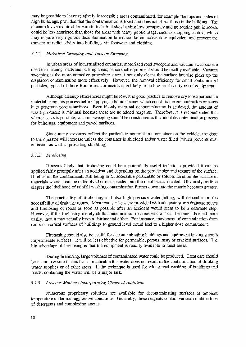
The removal of a fairly precisely defined layer, typically 1-3 cm from the surface of asphaltor concrete roads, using commercial equipment is a common procedure during road resurfacing(Fig. 2). Both cold planing for asphalt and concrete and hot planing for asphalt are used. The planerscan cut the surface with hard bits at speeds up to 4.5 km.^1 and milling widths up to 2.1 m and loadthe milled surface rubble directly into a truck. Although the use of such equipment to remove a layerof contaminated material from a road surface has not been reported, it is likely that very effectivedecontamination could be achieved. Costs for cleaning contaminated surfaces would be higher thanfor normal road work since methods to keep contaminated dust from spreading would be required, forexample wetting surfaces and spraying the rubble. Extra costs would arise if there were specialrequirements for disposal of the wastes.
FIG 2: Cold planer for removing a layer from concrete and asphalt surfaces(Credit Wirtgen.)
Such road planers, using different types of cutters for the removal of layers of earth, and directloading into trucks, might also have application in areas with fairly flat surfaces.
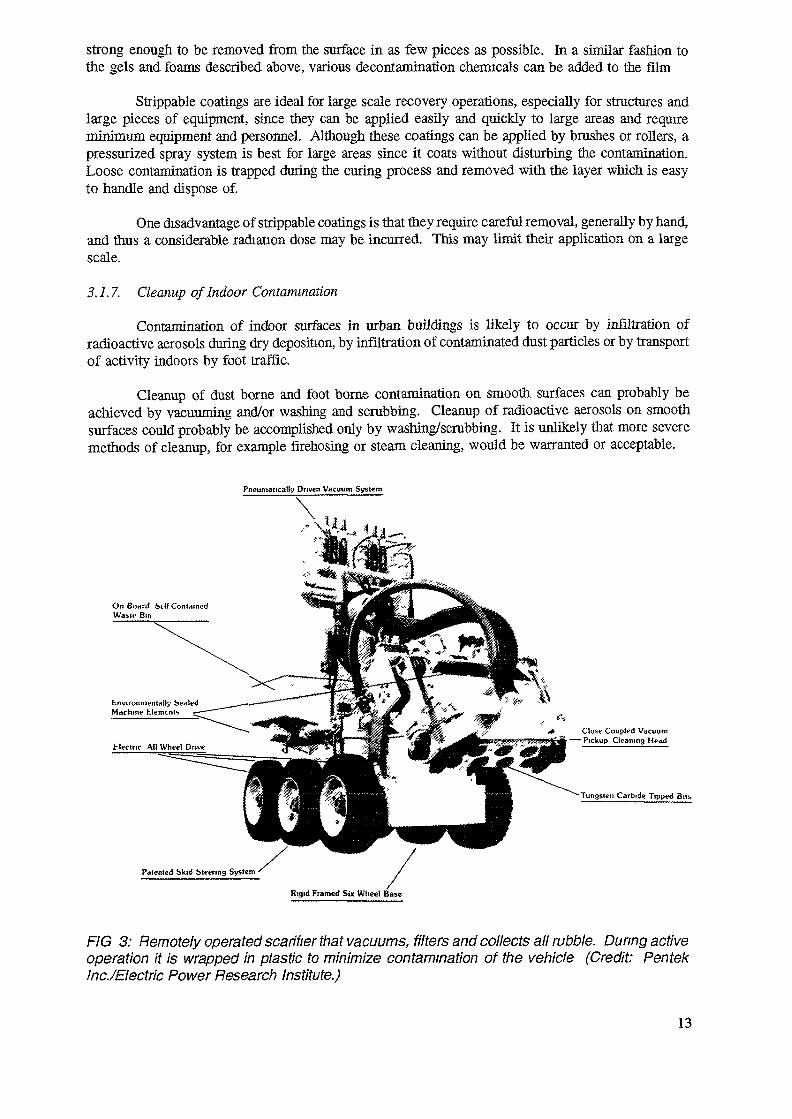
Smaller scale remotely operated scarifers have been used during the cleanup of various nuclearplants (Fig. 3).
A large number of hand held and large commercial grinders (Fig. 4) are available for removingthin layers of contaminated material from the surface of concrete. Some of the technology employedis an extension of highway grinding processes developed in the 1970s.
Road planers and grinders have limited applicability and would be expensive compared tocertain other techniques. However, in some cases the use of such equipment may be the only answer.
3.1.6. Strippable Coatings
Strippable coatings are liquids or gels which are applied to surfaces, allowed to dry, and thenstripped from the surface, carrying with them the loose contamination. The stripped film must be
12
strong enough to be removed from the surface in as few pieces as possible. In a similar fashion tothe gels and foams described above, various decontamination chemicals can be added to the film
Strippable coatings are ideal for large scale recovery operations, especially for structures andlarge pieces of equipment, since they can be applied easily and quickly to large areas and requireminimum equipment and personnel. Although these coatings can be applied by brushes or rollers, apressurized spray system is best for large areas since it coats without disturbing the contamination.Loose contamination is trapped during the curing process and removed with the layer which is easyto handle and dispose of.
One disadvantage of strippable coatings is that they require careful removal, generally by hand,and thus a considerable radiation dose may be incurred. This may limit their application on a largescale.
3.1.7. Cleanup of Indoor Contamination
Contamination of indoor surfaces in urban buildings is likely to occur by infiltration ofradioactive aerosols during dry deposition, by infiltration of contaminated dust particles or by transportof activity indoors by foot traffic.
Cleanup of dust borne and foot borne contamination on smooth surfaces can probably beachieved by vacuuming and/or washing and scrubbing. Cleanup of radioactive aerosols on smoothsurfaces could probably be accomplished only by washing/scrubbing. It is unlikely that more severemethods of cleanup, for example firehosing or steam cleaning, would be warranted or acceptable.
Pneumatically Driven Vacuum System
On Board Silf ContainedWaslf Bin
Close Coupled Vacuum—— Pickup Cleaning Head
Rigid Framed Six Wheel Base
FIG 3: Remotely operated scarifier that vacuums, filters and collects all rubble. During activeoperation it is wrapped in plastic to minimize contamination of the vehicle (Credit: PentekInc./Electric Power Research Institute.)
13
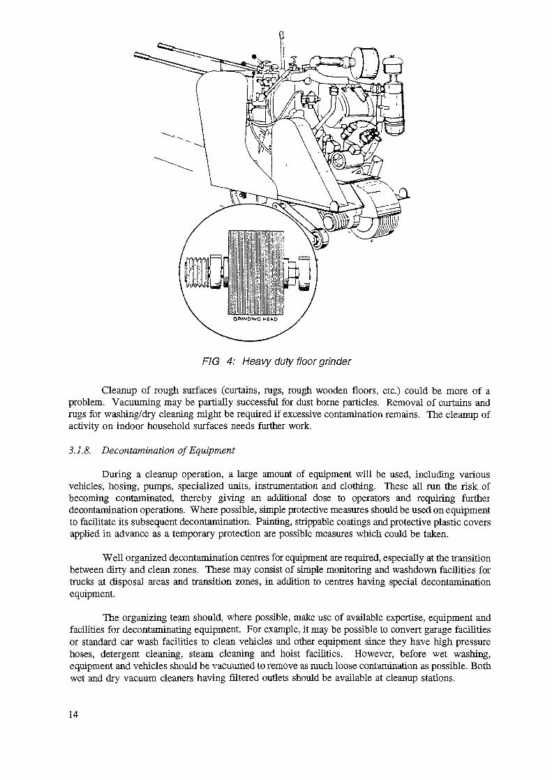
FIG 4: Heavy duty floor grinder
Cleanup of rough surfaces (curtains, rags, rough wooden floors, etc.) could be more of aproblem. Vacuuming may be partially successful for dust borne particles. Removal of curtains andrugs for washing/dry cleaning might be required if excessive contamination remains. The cleanup ofactivity on indoor household surfaces needs further work.
3.1.8. Decontamination of Equipment
During a cleanup operation, a large amount of equipment will be used, including variousvehicles, hosing, pumps, specialized units, instrumentation and clothing. These all run the risk ofbecoming contaminated, thereby giving an additional dose to operators and requiring furtherdecontamination operations. Where possible, simple protective measures should be used on equipmentto facilitate its subsequent decontamination. Painting, strippable coatings and protective plastic coversapplied in advance as a temporary protection are possible measures which could be taken.
Well organized decontamination centres for equipment are required, especially at the transitionbetween dirty and clean zones. These may consist of simple monitoring and washdown facilities fortrucks at disposal areas and transition zones, in addition to centres having special decontaminationequipment.
The organizing team should, where possible, make use of available expertise, equipment andfacilities for decontaminating equipment. For example, it may be possible to convert garage facilitiesor standard car wash facilities to clean vehicles and other equipment since they have high pressurehoses, detergent cleaning, steam cleaning and hoist facilities. However, before wet washing,equipment and vehicles should be vacuumed to remove as much loose contamination as possible. Bothwet and dry vacuum cleaners having filtered outlets should be available at cleanup stations.
14
Planning should include provision for the containment and treatment of waste water generatedduring cleanup.
Certain cleanup centres may contain specialized equipment for reclaiming valuable pieces ofequipment and instruments. Examples are: freon systems for cleaning electrical equipment,instruments, greasy items, clothing, etc., ultrasonic baths for cleaning tools, pumps, components,general equipment, etc.; and various chemical baths. Whether or not these specialized techniques andothers such as electropolishing are used, and the liming of such use, will depend on the accidentscenario, the availability of equipment and trained staff, the need for such techniques, etc.
During the cleanup of very large areas, the decontamination of clothing, overshoes, respiratorsand the other types of personal equipment used by the cleanup crews will be a major problemrequiring access to laundry and cleanup facilities. Various designs of laundry and cleanup facilitiesfor active clothing and gear are readily available for routine and emergency use. These facilities mayalso be required to clean up materials which have been contaminated by indoor deposition.
3.1.9. Guidance on the Selection and Application of Decontamination Methods
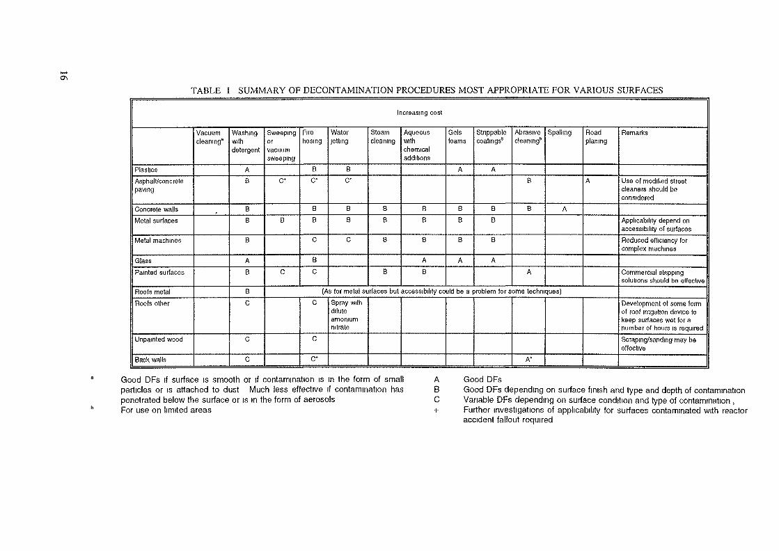
The previous subsections reviewed a number of decontamination procedures which could beused for various surfaces during large scale cleanup operations. A summary of the techniques(including simple vacuuming and washing) most appropriate to various surfaces is given in Table I.The techniques are shown in order of approximate cleanup cost per unit area. Some techniques suchas vacuuming and fire hosing can be applied relatively quickly by unskilled personnel. In other cases,e.g. abrasive blasting, much more planning, especially with attention to health physics precautions andwaste disposal, would be required.
Table II lists equipment which would be required or useful for cleanup of an urbanenvironment along with the skill requirements to operate such equipment. Equipment for monitoringor decontaminating personnel is not included in this list.
In general, it is recommended that vacuum sweeping and/or vacuuming be considered as theinitial decontamination process, especially if the contamination is in the form of dry loose particulatematerial. Even if only marginal decontamination is achieved, the amount of waste produced isminimal and the process does not fix the contamination to the surface or cause it to penetrate poroussurfaces. Use of this equipment in areas of medium to high activity would not be possible unlessshielded or remotely operated equipment is available. The use of vacuum cleaning for the inside orurban buildings and smooth building surfaces should be beneficial.
Firehosing is also recommended under controlled conditions, especially on smooth surfacessuch as roads and parking lots which need to be cleaned up quickly. However, it should only be usedif suitable drainage routes are available and contamination of drinking water does not occur.Firehosing should also be useful for decontaminating certain types of roofs, buildings and equipmenthaving smooth impermeable surfaces. Care must be taken to ensure fliat the process does not just shiftthe contamination from high surfaces to ground level, resulting in higher dose commitments.
If vacuuming followed by firehosing is not successful in cleaning up heavily contaminatedares, more aggressive methods such as abrasive cleaning, road planing or paint removal would berequired.
For decontamination of buildings a detailed survey of individual surfaces will be required.It is likely that contamination levels on different roofing materials will vary substantially. During thecleanup of urban areas, every effort should be made to select decontamination processes that minimizethe spread of contamination from exterior to interior surfaces. Interior contamination would generallycause higher dose commitments than contamination outside the building. When using road planing,
15
o\TABLE I SUMMARY OF DECONTAMINATION PROCEDURES MOST APPROPRIATE FOR VARIOUS SURFACES
Increasing cost
PlasticsAsphalt/concretepaving
Concrete wallsMetal surfaces
Metal machines
GlassPainted surfaces
Roofs metalRoofs other
Unpainted wood
Bnck walls
Vacuumcleaning8
Washingwithdetergent
AB
BB
B
AB
BC
C
C
Sweepingorvacuumsweeping
C*
B
C
Firehosing
BC*
BB
C
BC
Waterjetting
BC*
BB
C
Steamcleaning
BB
B
B
Aqueouswithchemicaladditions
BB
B
AB
Gelsfoams
A
BB
B
A
Stnppablecoatings'*
A
BB
B
A
Abrasivecleanmgb
B
B
A
Spelling
A
Roadplaning
A
(As for metal surfaces but accessibility could be a problem for some techniques)C
C
C*
Spray withdiluteamomumnitrate
A*
Remarks
Use of modified streetcleaners should beconsidered
Applicability depend onaccessibility of surfacesReduced efficiency forcomplex machines
Commercial strippingsolutions should be effective
Development of some formof roof irrigation device tokeep surfaces wet for anumber of hours is required
Scraping/sanding may beeffective
Good DFs if surface is smooth or if contamination is in the form of small Aparticles or is attached to dust Much less effective if contamination has Bpenetrated below the surface or is in the form of aerosols CFor use on limited areas +
Good DFsGood DFs depending on surface finish and type and depth of contaminationVariable DFs depending on surface condition and type of contamination ,Further investigations of applicability for surfaces contaminated with reactoraccident fallout required
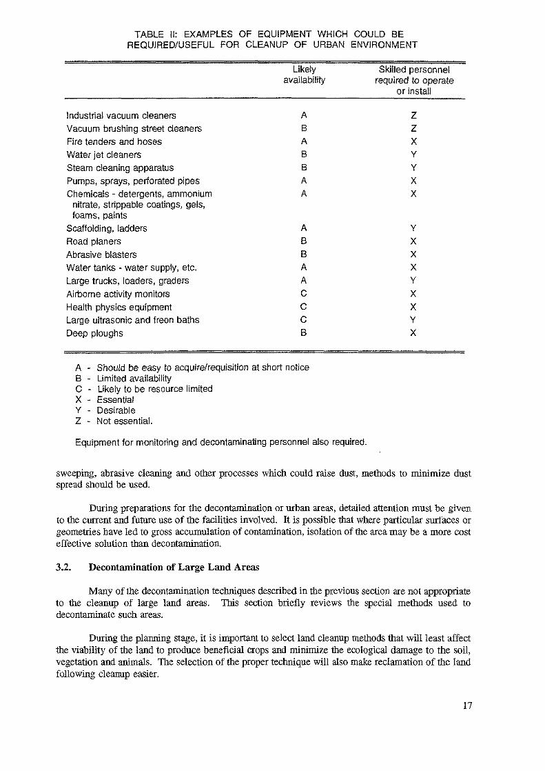
TABLE II: EXAMPLES OF EQUIPMENT WHICH COULD BEREQUIRED/USEFUL FOR CLEANUP OF URBAN ENVIRONMENT
Industrial vacuum cleanersVacuum brushing street cleanersFire tenders and hosesWater jet cleanersSteam cleaning apparatusPumps, sprays, perforated pipesChemicals - detergents, ammonium
nitrate, strippable coatings, gels,foams, paints
Scaffolding, laddersRoad planersAbrasive blastersWater tanks - water supply, etc.Large trucks, loaders, gradersAirborne activity monitorsHealth physics equipmentLarge ultrasonic and freon bathsDeep ploughs
Likelyavailability
ABABBAA
ABBAACCCB
Skilled personnelrequired to operate
or install
ZzXYYXX
YXXXYXXYX
A - Should be easy to acquire/requisition at short noticeB - Limited availabilityC - Likely to be resource limitedX - EssentialY - DesirableZ - Not essential.
Equipment for monitoring and decontaminating personnel also required.
sweeping, abrasive cleaning and other processes which could raise dust, methods to minimize dustspread should be used.
During preparations for the decontamination or urban areas, detailed attention must be givento the current and future use of the facilities involved. It is possible that where particular surfaces orgeometries have led to gross accumulation of contamination, isolation of the area may be a more costeffective solution than decontamination.
3.2. Decontamination of Large Land Areas
Many of the decontamination techniques described in the previous section are not appropriateto the cleanup of large land areas. This section briefly reviews the special methods used todecontaminate such areas.
During the planning stage, it is important to select land cleanup methods that will least affectthe viability of the land to produce beneficial crops and minimize the ecological damage to the soil,vegetation and animals. The selection of the proper technique will also make reclamation of the landfollowing cleanup easier.
17
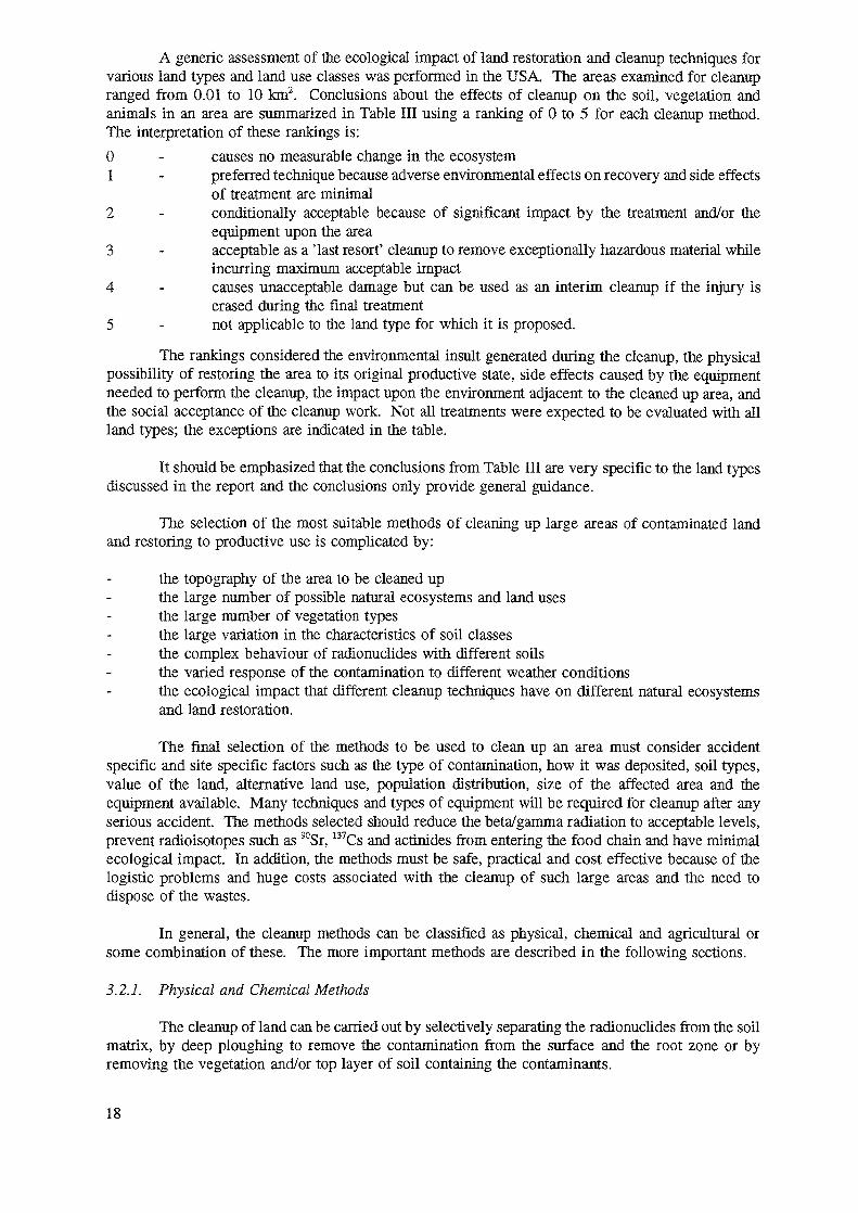
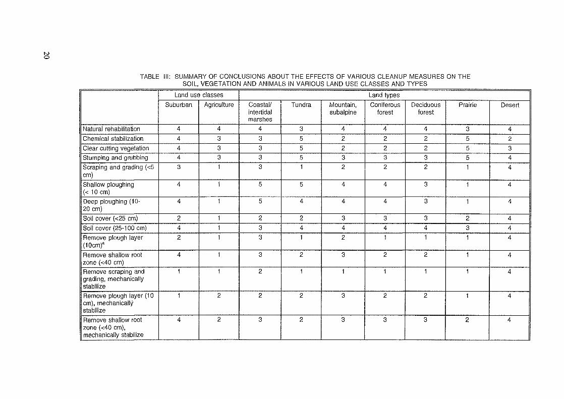
A generic assessment of the ecological impact of land restoration and cleanup techniques forvarious land types and land use classes was performed in the USA. The areas examined for cleanupranged from 0.01 to 10 km2. Conclusions about the effects of cleanup on the soil, vegetation andanimals in an area are summarized in Table III using a ranking of 0 to 5 for each cleanup method.The interpretation of these rankings is:0 - causes no measurable change in the ecosystem1 - preferred technique because adverse environmental effects on recovery and side effects
of treatment are minimal2 - conditionally acceptable because of significant impact by the treatment and/or the
equipment upon the area3 - acceptable as a 'last resort' cleanup to remove exceptionally hazardous material while
incurring maximum acceptable impact4 - causes unacceptable damage but can be used as an interim cleanup if the injury is
erased during the final treatment5 - not applicable to the land type for which it is proposed.
The rankings considered the environmental insult generated during the cleanup, the physicalpossibility of restoring the area to its original productive state, side effects caused by the equipmentneeded to perform the cleanup, the impact upon the environment adjacent to the cleaned up area, andthe social acceptance of the cleanup work. Not all treatments were expected to be evaluated with allland types; the exceptions are indicated in the table.
It should be emphasized that the conclusions from Table III are very specific to the land typesdiscussed in the report and the conclusions only provide general guidance.
The selection of the most suitable methods of cleaning up large areas of contaminated landand restoring to productive use is complicated by:
the topography of the area to be cleaned upthe large number of possible natural ecosystems and land usesthe large number of vegetation typesthe large variation in the characteristics of soil classesthe complex behaviour of radionuclides with different soilsthe varied response of the contamination to different weather conditionsthe ecological impact that different cleanup techniques have on different natural ecosystemsand land restoration.
The final selection of the methods to be used to clean up an area must consider accidentspecific and site specific factors such as the type of contamination, how it was deposited, soil types,value of the land, alternative land use, population distribution, size of the affected area and theequipment available. Many techniques and types of equipment will be required for cleanup after anyserious accident. The methods selected should reduce the beta/gamma radiation to acceptable levels,prevent radioisotopes such as 90Sr, 137Cs and actinides from entering the food chain and have minimalecological impact. In addition, the methods must be safe, practical and cost effective because of thelogistic problems and huge costs associated with the cleanup of such large areas and the need todispose of the wastes.
In general, the cleanup methods can be classified as physical, chemical and agricultural orsome combination of these. The more important methods are described in the following sections.
3.2.1. Physical and Chemical Methods
The cleanup of land can be carried out by selectively separating the radionuclides from the soilmatrix, by deep ploughing to remove the contamination from the surface and the root zone or byremoving the vegetation and/or top layer of soil containing the contaminants.
18
The volume of wastes arising from the cleanup would be smallest for deep ploughing andlargest for layer removal. The volume of wastes from the separation technique would depend on howwell the separation could he done. The cost of storing, transporting, additional treatment and/ordisposal of contaminated soils and vegetation is an important factor in selecting the proper method.For example, if the disposal area is a long distance from the wastes, transportation costs could exceedall other costs if the layer removal technique was used.
3.2.1.1. Physical and Chemical Separation of Radionuclides from the Soil
Separation of radionuclides from soil is desirable since it can significantly reduce the volumesof wastes which have to be transported and disposed of. In principle, this technique is applicable onlyto coarser grained soil or gravel in which the radionuclides are associated with fine grained particleswhich can easily be separated. The technique is most practical if the area to be decontaminated isrelatively small. However, since physical separation of radionuclides is almost always associated withthe removal of the clay fraction of the soil matrix, the process will result in a decrease in soil fertility.If the land is to be used for crop production, addition of fertilizers after the cleanup will be necessaryto restore land fertility.
Two physical techniques have been investigated, inertial separation and gravitationalseparation. The decontamination of soils using these methods can be carried out using water, chemicalwash solutions or chemical separation processes.
3.2.1.2. Deep Ploughing
Deep ploughing has been investigated to a limited extent in several countries as an alternativeto the removal of the contaminated soil layer. Typically, a tractor drawn trenching plough is used tocompletely invert a thick layer of soil, placing the active top 10 cm at the bottom and moving the deepclean layers to the top. In theory, with this method the major part of the activity would be placed wellbelow the lower boundary of the roots of the crop. However, ploughing does not result in the perfectturnover of soil layers and some mixing of layers occurs. The extent of this mixing has beeninvestigated to some extent but further work needs to be done. Before a decision is made for deepploughing, an evaluation of the impact on soil fertility and productivity should be conducted. Theimpact of deep ploughing appears to be influenced by the type of soil and the crops grown.
It is evident that further study is required to determine when and if ploughing should be usedas a cleanup procedure. The primary benefit would be the reduction in external radiation levels at thesurface. The benefit regarding soil-plant transfer will depend on the depth of ploughing, soil type, howthe ploughing affects the vertical distribution, the root depth of plants, etc. Even for acceptablecircumstances, the cost-benefit advantage of ploughing versus other methods and the depth ofploughing must be carefully considered. In some areas, the presence of land drainage systems andsubsurface items such as cabling may limit the depth to which land can be ploughed.
If deep ploughing is used, the replacement of deep-rooted plants by shallow- rooted plants maybe desirable.
3.2.1.3. Removal of Vegetation
Since under certain conditions vegetation can intercept almost all of the fallout, its removalcould be an effective method of decontaminating certain areas.
The removal of contaminated vegetation appears to be an effective method of decontaminatingland under certain conditions. The effectiveness of the technique depends on the density and type ofvegetation, on the nature of the contaminant and the method of application (wet/dry). In any event itmay be necessary to remove surface vegetation to permit subsequent treatment of the soil surface.
19
too
TABLE III: SUMMARY OF CONCLUSIONS ABOUT THE EFFECTS OF VARIOUS CLEANUP MEASURES ON THESOIL, VEGETATION AND ANIMALS IN VARIOUS LAND USE CLASSES AND TYPES
Natural rehabilitationChemical stabilizationClear cutting vegetationStumping and grubbingScraping and grading (<5cm)Shallow ploughing(< 1 0 cm)Deep ploughing (ID-20 cm)Soil cover (<25 cm)Soil cover (25-1 00 cm)Remove plough layer(10cm)a
Remove shallow rootzone (<40 cm)Remove scraping andgrading, mechanicallystabilizeRemove plough layer (10cm), mechanicallystabilizeRemove shallow rootzone (<40 cm),mechanically stabilize
Land use classesSuburban
44443
4
4
242
4
1
1
4
Agriculture
43331
1
1
111
1
1
2
2
Land typesCoastal/intertidalmarshes
43333
5
5
233
3
2
2
3
Tundra
35551
5
4
241
2
1
2
2
Mountain,subalpine
42232
4
4
342
3
1
3
3
Coniferousforest
42232
4
4
341
2
1
2
3
Deciduousforest
42232
3
3
341
2
1
2
3
Prairie
35551
1
1
231
1
1
1
2
Desert
42344
4
4
444
4
4
4
4
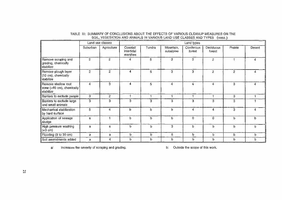
TABLE III: SUMMARY OF CONCLUSIONS ABOUT THE EFFECTS OF VARIOUS CLEANUP MEASURES ON THESOIL, VEGETATION AND ANIMALS IN VARIOUS LAND USE CLASSES AND TYPES (cont.)
Remove scraping andgrading, chemicallystabilizeRemove plough layer(10 cm), chemicallystabilizeRemove shallow rootzone (<40 cm), chemicallystabilizeBarriers to exclude peopleBarriers to exclude largeand small animalsMechanical stabilizationby hard surfaceApplication of sewagesludgeHigh pressure washing(<3 cm)Flooding (3 to 30 cm)Soil amendments added
Land use classesSuburban
2
2
4
33
5
a
a
aa
Agriculture
2
2
3
23
4
1
a
a4
Land typesCoastal/intertidalmarshes
4
4
4
13
b
b
b
bb
Tundra
6
5
5
13
b
b
b
bb
Mountain,subalpine
3
3
4
13
b
b
3
5b
Coniferousforest
3
3
4
13
4
0
b
bb
Deciduousforest
2
2
4
13
4
0
b
bb
Prairie
1
2
3
33
3
b
b
bb
Desert
4
4
4
11
4
b
b
bb
a: Increases the severity of scraping and grading. b: Outside the scope of this work.
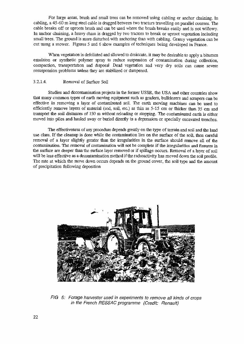
For large areas, brush and small trees can be removed using cabling or anchor chaining. Incabling, a 45-60 m long steel cable is dragged between two tractors travelling on parallel courses. Thecable breaks off or uproots brush and can be used where the brush breaks easily and is not willowy.In anchor chaining, a heavy chain is dragged by two tractors to break or uproot vegetation includingsmall trees. The ground is more disturbed with anchoring than with cabling. Grassy vegetation can becut using a mower. Figures 5 and 6 show examples of techniques being developed in France.
When vegetation is defoliated and allowed to desiccate, it may be desirable to apply a bitumenemulsion or synthetic polymer spray to reduce suspension of contamination during collection,compaction, transportation and disposal Dead vegetation and very dry soils can cause severeresuspension problems unless they are stabilized or dampened.
3.2.1.4. Removal of Surface Soil
Studies and decontamination projects in the former USSR, the USA and other countries showthat many common types of earth moving equipment such as graders, bulldozers and scrapers can beeffective in removing a layer of contaminated soil. The earth moving machines can be used toefficiently remove layers of material (sod, soil, etc.) as thin as 5-15 cm or thicker than 35 cm andtransport the soil distances of 150 m without reloading or stopping. The contaminated earth is eithermoved into piles and hauled away or buried directly in a depression or specially excavated trenches.
The effectiveness of any procedure depends greatly on the type of terrain and soil and the landuse class. If the cleanup is done while the contamination lies on the surface of the soil, then carefulremoval of a layer slightly greater than the irregularities in the surface should remove all of thecontamination. The removal of contamination will not be complete if the irregularities and fissures inthe surface are deeper than the surface layer removed or if spillage occurs. Removal of a layer of soilwill be less effective as a decontamination method if the radioactivity has moved down the soil profile.The rate at which the move down occurs depends on the ground cover, the soil type and the amountof precipitation following deposition
FIG 5: Forage harvester used in experiments to remove all kinds of cropsin the French RESSAC programme (Credit: Renault)
22
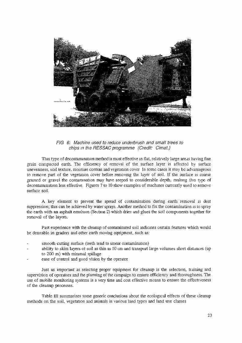
FIG 6: Machine used to reduce underbrush and small trees tochips in the RES SAC programme (Credit: Cimat.)
This type of decontamination method is most effective m flat, relatively large areas having finegrain compacted earth. The efficiency of removal of the surface layer is affected by surfaceunevenness, soil texture, moisture content and vegetation cover In some cases it may be advantageousto remove part of the vegetation cover before removing the layer of soil. If the surface is coarsegrained or gravel the contamination may have seeped to considerable depth, making this type ofdecontamination less effective. Figures 7 to 10 show examples of machines currently used to removesurface soil.
A key element to prevent the spread of contamination during earth removal is dustsuppression; this can be achieved by water sprays. Another method to fix the contamination is to spraythe earth with an asphalt emulsion (Section 2) which dries and glues the soil components together forremoval of the layers.
Past experience with the cleanup of contaminated soil indicates certain features which wouldbe desirable in graders and other earth moving equipment, such as:
smooth cutting surface (teeth tend to smear contamination)ability to skim layers of soil as thin as 10 cm and transport large volumes short distances (upto 200 m) with minimal spillageease of control and good vision by the operator
Just as important as selecting proper equipment for cleanup is the selection, training andsupervision of operators and the planning of the campaign to ensure efficiency and thoroughness. Theuse of mobile monitoring systems is a very time and cost effective means to ensure the effectivenessof the cleanup processes.
Table III summarizes some generic conclusions about the ecological effects of these cleanupmethods on the soil, vegetation and animals in various land types and land use classes
23
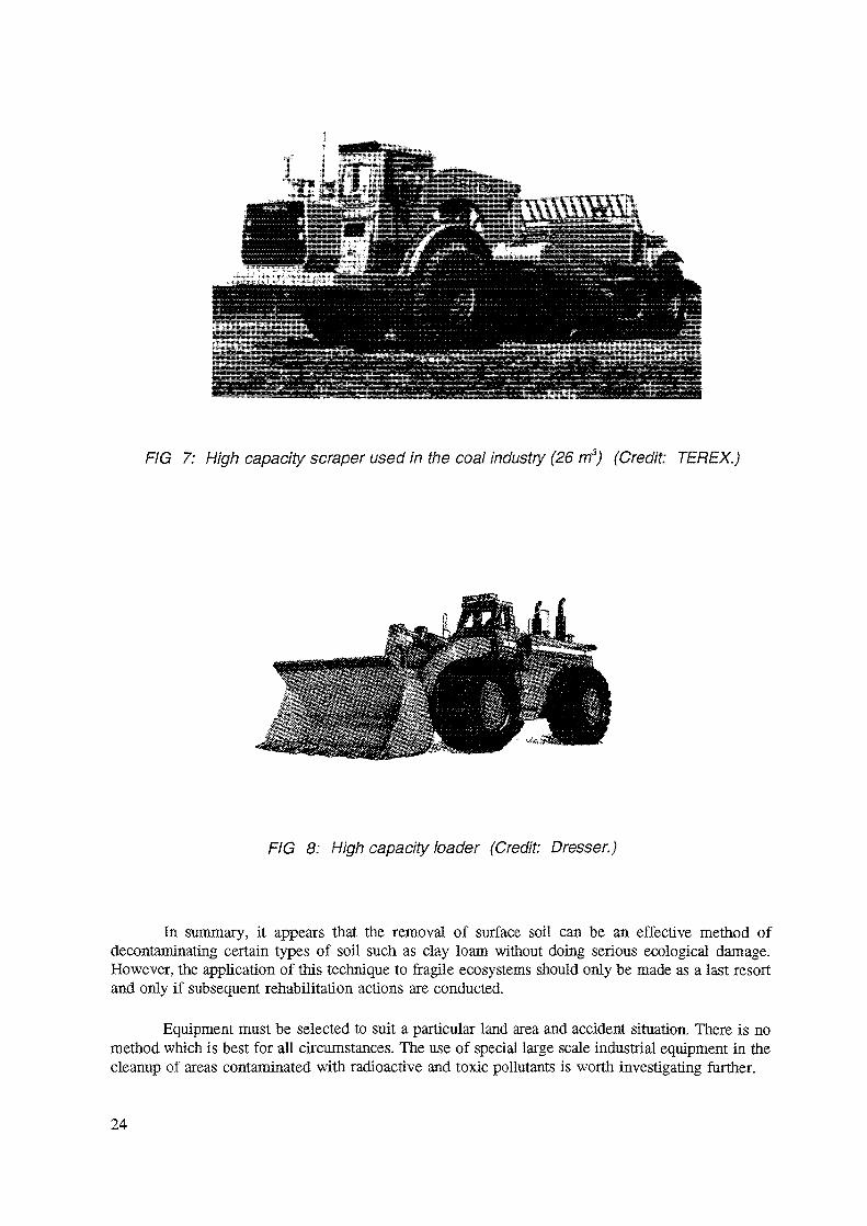
FIG 7: High capacity scraper used in the coal industry (26 m3) (Credit TEREX.)
FIG 8: High capacity loader (Credit: Dresser.)
In summary, it appears that the removal of surface soil can be an effective method ofdecontaminating certain types of soil such as clay loam without doing serious ecological damage.However, the application of this technique to fragile ecosystems should only be made as a last resortand only if subsequent rehabilitation actions are conducted.
Equipment must be selected to suit a particular land area and accident situation. There is nomethod which is best for all circumstances. The use of special large scale industrial equipment in thecleanup of areas contaminated with radioactive and toxic pollutants is worth investigating further.
24
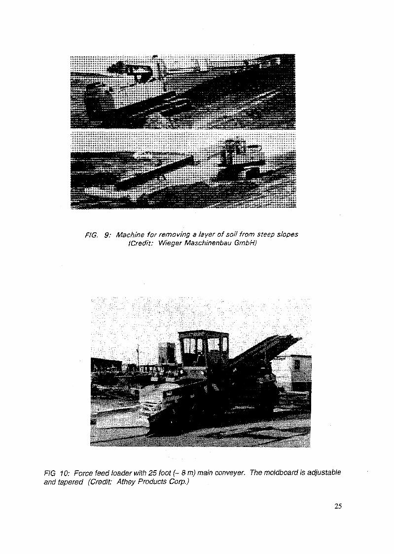
FIG. 9: Machine for removing a layer of soil from steep slopes(Credit: Wieger Maschinenbau GmbH)
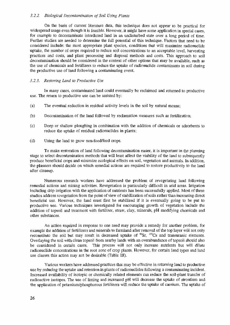
FIG 10: Force feed loader with 25 foot (~ 8 m) main conveyer. The moldboard is adjustableand tapered (Credit: Athey Products Corp.)
25
5.2.2. Biological Decontamination of Soil Using Plants
On the basis of current literature data, this technique does not appear to be practical forwidespread usage even though it is feasible. However, it might have some application in special cases,for example to decontaminate interdicted land in an undisturbed state over a long period of time.Further studies are needed to determine the full potential of this technique. Factors that need to beconsidered include: the most appropriate plant species, conditions that will maximize radionuclideuptake, the number of crops required to reduce soil concentrations to an acceptable level, harvestingpractices and costs, and plant processing and disposal methods and costs. This approach to soildecontamination should be considered in the context of other options that may be available, such asthe use of chemicals and fertilizers to reduce the uptake of radionuclide contaminants in soil duringthe productive use of land following a contaminating event.
5.2.3. Restoring Land to Productive Use
In many cases, contaminated land could eventually be reclaimed and returned to productiveuse. The return to productive use can be assisted by:
(a) The eventual reduction in residual activity levels in the soil by natural means;
(b) Decontamination of the land followed by reclamation measures such as fertilization;
(c) Deep or shallow ploughing in combination with the addition of chemicals or adsorbents toreduce the uptake of residual radionuclides in plants;
(d) Using the land to grow non-food/feed crops.
To make restoration of land following decontamination easier, it is important in the planningstage to select decontamination methods that will least affect the viability of the land to subsequentlyproduce beneficial crops and minimize ecological effects on soil, vegetation and animals. In addition,the planners should decide on which remedial actions are required to restore productivity to the landafter cleanup.
Numerous research workers have addressed the problem of revegetating land followingremedial actions and mining activities. Revegetation is particularly difficult in arid areas. Irrigationincluding drip irrigation with the application of nutrients has been successfully applied. Most of thesestudies address revegetation from the point of view of stabilization of soils rather than increasing directbeneficial use. However, the land must first be stabilized if it is eventually going to be put toproductive use. Various techniques investigated for encouraging growth of vegetation include theaddition of topsoil and treatment with fertilizer, straw, clay, minerals, pH modifying chemicals andother substances.
An action required in response to one need may provide a remedy for another problem, forexample the addition of fertilizers and minerals to farmland after removal of the top layer will not onlyreconstitute the soil but may result in decreased uptake of 90Sr, 137Cs and transuranic elements.Overlaying the soil with clean topsoil from nearby lands with an overabundance of topsoil should alsobe considered in certain cases. This process will not only increase nutrients but will diluteradionuclide concentrations in the root zone of crop plants. However, for certain land types and landuse classes this action may not be desirable (Table III).
Various workers have addressed practices that may be effective in returning land to productiveuse by reducing the uptake and retention in plants of radionuclides following a contaminating incident.Increased availability of isotopic or chemically related elements can reduce the soil-plant transfer ofradioactive isotopes. The use of liming and increased pH will decrease the uptake of strontium andthe application of potassium/phosphorous fertilizers will reduce the uptake of caesium. The uptake of
26
potassium rich fertilizers reduced the uptake of 137Cs by an order of magnitude in a variety of tropicalcrops. To get a reliable estimate of tiie usefulness of such techniques to assist in the reclamation ofcontaminated land the following considerations should be kept in mind. Adding fertilizers or chemicalanalogues creates a competition with the radionuclide at the plant root absorbing zone, and thereforea lower contamination level in the plant should be expected. However, a similar competition may alsooccur at the soil absorbing sites, resulting in an increase in bioavailability and higher levels ofcontamination in the plant. Therefore, depending on the chemical nature of the radionuclide, the soiltype and the plant species, a reduction or increase of the plant contamination level may then occur.Much insight into the basic principles of soil and root absorption has to be obtained before thesemethods can reliably be applied to reclaim land.
Selective removal of 137Cs from soil poses a more difficult problem owing to the lack ofsuitable complexing agents. Although compounds such as crown ethers will complex caesium, theyare quite toxic and very expensive. Hence they would not be suitable for application on a large scale.These techniques with complexing agents may have serious drawbacks since most of them moreeffectively bind the micronutrients indispensable for healthy plant growth, and these will not be fullyrestored by fertilization techniques. The cost-benefit analysis of such practices moreover, will needcareful consideration.
Land may be reclaimed and used for productive purposes, even if there is some residualcontamination, by the judicious selection of crops. For example, the cultivation of non-food/feed cropssuch as cotton, flax and timber could be considered if food crops would contain unacceptableconcentrations of radionuclides. Again, the content of radionuclides such as 90Sr should be very lowin corn since it has one of the lowest mineral contents of all grains and would be safe to grow oncontaminated land.
Land could also be restored to productive use by growing sugar and oil producing crops sincemost of the radioactivity in the refined products would be removed during processing. However, if theby-products, such as sugarbeet pulp, are fed to animals for meat production, the indirect contributionof radionuclides to the human diet would have to be considered.
Changed practices such as the planting of deep-rooted rather than shallow- rooted crops wouldbe expected to reduce the uptake of radionuclides unless the activity has penetrated well below thesurface as a result of deep ploughing or for natural reasons.
The available information on the reclamation of land and land use does not constitute a bodyof facts that can be translated into specific and precise guidance to be followed in agricultural practicesafter a contamination incident. However, current information and experience that is now beingaccumulated in the aftermath of the Chernobyl accident should be helpful in selecting practices thatwill enhance the beneficial use of land.
4. LOADING AND TRANSPORTING LARGE VOLUMES OF WASTES
Large volumes of contaminated soil, concrete, asphalt, equipment, vegetation, etc. could arisefrom the cleanup of a large area contaminated as a result of a serious accident at a nuclear powerplant. The removal of a thin (average thickness of about 5 cm) layer of contaminated material froma 7 km radius around a damaged facility could result in 8 x 10s m3 of waste which has to betransported to a disposal site and buried. The loading and moving of such large volumes of soil is timeconsuming and expensive but the experience is not unique.
For example, during the construction of large earth dams, millions of cubic metres of inactivesoil and concrete have to be loaded and moved. It is also common to load and move large volumesof product and waste rock in mining.
27
During the cleanup of very large contaminated areas, the loading and transportation of muchof the wastes to the disposal site could probably be accomplished using conventional earth movingequipment from the construction industry. Some modifications may be beneficial, such as the additionof shielding between the driver's cab and the box of the dump truck. If the disposal site is locatedwithin the cleanup area, much larger equipment such as that used on the site in major civil engineeringand mineral extraction projects could be used.
The loading of the contaminated soil could be done:••'o
(a) Using equipment such as wheeled or tracked loaders and excavator loaders with capacities of30 m3 or more. The material would first be moved into piles using conventional grader/planersor bulldozers with wide blades.
(b) Using a force feed loader with a conveyor which can pick up a layer of soil or soil from largewindrows and dump it directly onto a truck. On flat surfaces it may be possible to use amodified road planer.
(c) Using vacuum pickup systems for certain types of soil under dry conditions.
Water spraying equipment, to dampen soils during handling under very dry conditions, maybe useful to minimize dust production.
Highly contaminated soil from locations close to the damaged facility may have to be sealedin appropriate containers for transport. Remotely operated equipment or units with shielded/air filteredcabs would be required.
The contaminated wastes could be transported using one or more of the following techniques:
(1) Moving the layer of contaminated soil directly into depressions or specially excavated trenchesusing scrapers, bulldozers or graders. The soil can be moved 100-150 m without reloading orstopping.
(2) Loading the soil into dump trucks for transport to the disposal site. Rear dumping trucks areavailable with capacities of up to 250 t.
(3) Loading the soil into railway cars for transport to the disposal site. The choice of rail transportdepends on the availability of railway lines in the vicinity of the cleanup and disposal sites.If double or triple handling of material is required, as in a truck-rail-truck transportationsystem, Canadian analyses suggest that rail transport is not cost effective for distances lessthan a few hundred kilometres. However, the economic factor in the decision may be offsetby the fact that rail transport results in smaller radiation exposure to transportation workersand involves less interaction with the public than does truck transport.
Effective management and control systems will be required to move and dispose of largequantities of earth safely. The protection of the operational staff and the environment must beimportant factors during the planning and cleanup. One of the biggest problems on a job of suchmagnitude may be to ensure continual maintenance of safety and health physics procedures once thejob becomes routine.
In planning for the loading and transport of these wastes there are certain basic requirements:
a modified waybill control technique in conjunction with a data handling system to control theloading, transport and disposal of wastes;
28
well defined transportation routes and truck control points to ensure compliance with therouting plan;
truck cleanup areas and monitoring points either at the dump site or between the contaminatedand clean zones;
an emergency response plan for implementation in the event of a transportation accident.
5. DISPOSAL OF LARGE VOLUMES OF WASTES
The objective of disposing of radioactive wastes is to confine the radionuclides within therepository site until they no longer represent an unacceptable risk to the environment and the public.A repository should fulfil two important and related functions in this regard: firstly to limit dispersionof the radionuclides contained in the wastes by water-borne and airborne pathways and to protect thewaste from surface and near surface deteriorating processes such as erosion or intrusion by humans,burrowing animals or deep-rooted vegetation.
The radionuclides of longer term concern in the soil after an accident at a nuclear power plantare 90Sr and 137Cs, both with a half-life of approximately 30 years. After about 300 years, theconcentrations of these radionuclides in soil would be about 0.1% of the concentrations after theaccident. Therefore, a storage facility capable of containing these wastes for several hundred yearsshould be suitable for most of the soils collected.
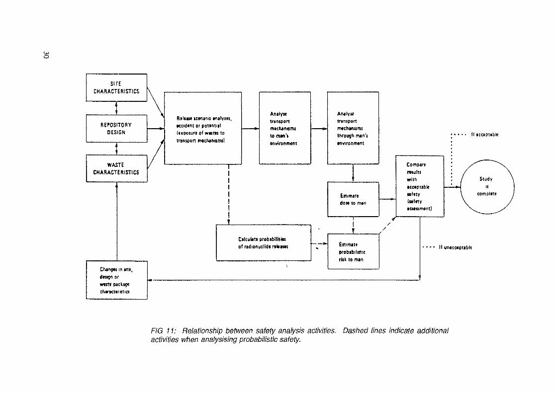
The type of facility selected for disposal of the soil will be dictated by many factors, includingthe availability of equipment to move the wastes, the volumes to be moved, the distances involved,the availability of natural or man-made disposal sites such as quarries, mines or depressions and thehydrogeology and geology of the area. The basic factors which must be considered in order to achievea suitable disposal repository system are: the quantity and nature of the wastes, the engineeringfeatures incorporated into the repository design, the site characteristics and the time period allowedfor institutional control. Conditions are combined in the safety assessment (Fig. 11) to achieve adisposal system that will meet the regulatory or desired environmental protection requirements. Forexample, a special cover to prevent intrusion by humans would not be required if the institutionalcontrol period is expected to be longer than the hazardous life of the wastes.
While the specifics of any accident will affect the disposal plan, some general guidance canbe offered regarding disposal of large volumes of contaminated soils.
5.1. Methods for Storing/Disposing of Large Volumes of Wastes
A variety of generic designs are available for the storage/disposal of the very large volumesof contaminated soil and other bulk materials arising from the cleanup after a major nuclear accidentThese designs include:
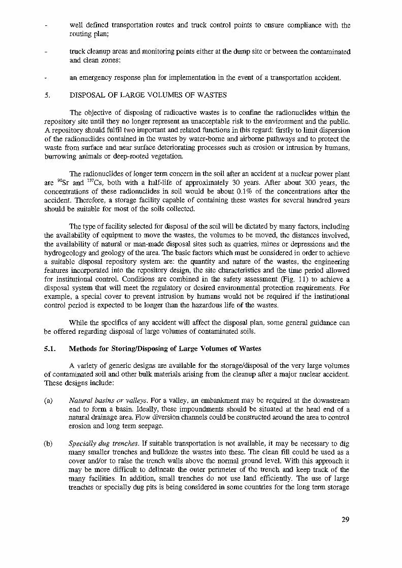
(a) Natural basins or valleys. For a valley, an embankment may be required at the downstreamend to form a basin. Ideally, these impoundments should be situated at the head end of anatural drainage area. Flow diversion channels could be constructed around the area to controlerosion and long term seepage.
(b) Specially dug trenches. If suitable transportation is not available, it may be necessary to digmany smaller trenches and bulldoze the wastes into these. The clean fill could be used as acover and/or to raise the trench walls above the normal ground level. With this approach itmay be more difficult to delineate the outer perimeter of the trench and keep track of themany facilities. In addition, small trenches do not use land efficiently. The use of largetrenches or specially dug pits is being considered in some countries for the long term storage
29
SITECHARACTERISTICS
REPOSITORYDESIGN
WASTECHARACTERISTICS
Rile«*t tcvnano milym,tccidtm or pottntitl(txpoturt of waim totransport nwctwrmrra)
Ctonpt* m tnt,
Antlysctrtntponm*ch*nitmtto men's*nvironnwnt
Antlyutransportmvchanumsthrough mtn'ienviron m«ni
Ettimsttdot* to nun
Cilcutttt probabilHittof ndionudidi nKtm Etlimtti
probabilisticttst to m*n
II sccspubk
Comptrtmultswith•cetpubk
If untccaptable
FIG 11: Relationship between safety analysis activities,activities when analysising probabilistic safety.
Dashed lines indicate additional
of uranium mill tailings to eliminate the risks associated with possible embankment failuresin other facility designs. Large trenches or pits using this engineering technology or that usedfor well engineered municipal disposal areas could also be constructed for the disposal of largevolumes of contaminated soil.
(c) Mined out quarries or open pit mines. The possibility of using these depends on climate,groundwater depth and variability, permeability of rock walls, susceptibility of the pit toflooding, etc. If a particular quarry is considered especially desirable, some of the aboveproblems can be reduced by using engineered features such as a rock filled hydraulic bypass,clay lining and a clay-rip-earth cover.
(d) Underground mines. Some wastes could be disposed of in underground mines which no longerhave any valuable mineral resources. The usefulness of this approach would depend on manyfactors, including groundwater depth and movement through the mine and susceptibility toflooding. These aspects could be difficult to characterize at short notice.
(e) Large mounds. The mounds would be covered with clay, other soil and/or a rip-rap cover ofrock.
If necessary, the impoundment facility could be lined with clay (if available) or otherimpermeable barriers to minimize leakage. Siting of the disposal facility on an area of impermeableclay geology would eliminate reliance on the integrity of an engineered clay liner. Infiltration ofprecipitation into the waste can be controlled using an impermeable cover such as clay and suitabledrainage. Intrusion by man, animals or plants into the wastes can be minimized using a rock rip-rapand/or thicker cover.
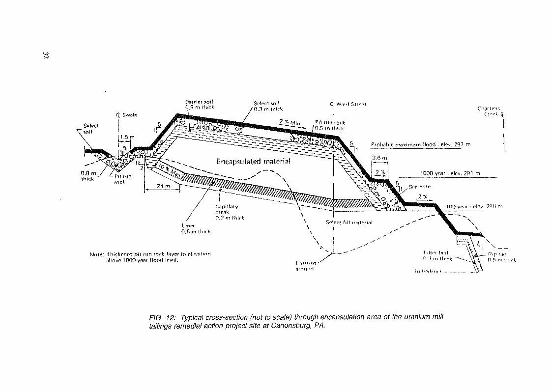
Impoundment facilities are currently in use to hold very large volumes of uranium mill tailingsduring the operational phase of the mill. In these operations, the uranium tailings are pumped as aslurry to fill up impoundments based on some of me generic designs described (Fig. 12). The latestfacilities are being designed and closed out so that the release of pollutants such as 226Ra, radon, acidsand heavy metals will stay within authorized limits for at least 1000 years. Although the soil arisingfrom a reactor accident will not be in a slurry form, much of the generic information on theconstruction and closeout of certain designs of mill tailing impoundment facilities would be of greatuse in designing and building disposal sites for contaminated soils.
The wastes from areas very close to an accident may require special handling and disposal.For example, selected wastes may be collected in containers and buried under the low level wastes.If long lived actinides are present in significant concentrations, the wastes may have to be disposedof in special disposal areas.
In many countries, disposal facilities require institutional control and monitoring programmesuntil they are finally closed out, using features which prevent intrusion and control seepage withinregulatory limits.
The cost to clean up, transport and dispose of large volumes of contaminated material will behigh and may have some impact on the selected cleanup criteria through cost-benefit analysis.
5.2. Site Selection
The choice of the location and the method of disposal can be dictated by many factorsincluding economics, availability of equipment, the radionuclides involved, the climate and theavailability of disposal sites and their characteristics. The cost of loading, packaging and transportingthe very large volumes of wastes from contaminated land can significantly influence the choice ofdisposal site. Societal implications can also be important but this factor will probably not have a largeeffect in an emergency situation.
31
Barrlpr soil0.9 m thick
Spinet soi!'0.3 m Ilii
5 Pfobobla tnoximum flood • ctfv. 2971
Encapsulated material
Nnlr;: fhkknnrd pit run cork layer In nlnabovo lOnOVi" 'lootl
it l-r-,lm. V .. _ __ _N>
F/G 12: Typical cross-section (not to scale) through encapsulation area of the uranium milltailings remedial action project site at Canonsburg, PA.
The idealized sequence of investigation for the selection of any waste disposal site has fourgeneral phases:
planning and general studiesarea surveypreliminary site selectionsite confirmation.
During the preliminary planning, potential sites for the disposal of very large volumes ofcontaminated wastes could be examined using available data or new core samples if funding isavailable. However, since even the selection of potential sites could be a very sensitive issue, it mayonly be possible to do this study in a generic manner and to match repository designs with genericsites in the area. Hydrological considerations in site selection are described in Table IV.
6. COMPLIANCE WITH RELEASE CRITERIA
The decision to implement the cleanup of a contaminated area is made on the basis of theDerived Intervention Levels (DDLs) for this protective measure. Once the decision has been made, thencleanup criteria should be available to define the specific radionuclide concentration limit or gammaexposure level which should be achieved by remedial action in a particular area. In addition, re-entrycriteria should be established by which it can be decided whether to allow the return of the populationand/or reuse of the land for agriculture, etc.
The development of such criteria which relate the dose to humans to contamination levelsusing pathway analysis is difficult for small sites and extremely difficult for large diverse regions. Inpractice, different acceptance criteria may be set for different zones or situations in large contaminatedareas. Fortunately, by the time large scale cleanup is initiated, only a few longer lived radionuclideswould need to be considered in setting criteria,
It is beyond the scope of this report to give detailed guidance on the development of suchcriteria since it is a specialized task. However, the criteria should be based on risk levels translatedinto acceptable dose limits. For rural areas, concentration limits for radionuclides in soil, water, air andfood or acceptable radiation levels can be derived using suitable pathway analysis and, where possible,realistic site specific parameters. For urban areas, an integrated evaluation of the radiation from varioussurfaces should be undertaken.
Just as important as the cleanup and release criteria are the validation and quality controlprotocols required to ensure compliance with these criteria,
6.1. Basic Steps
The basic steps in developing and implementing a plan to ensure that areas, buildings,materials and equipment being released for reuse comply with release criteria include:
(a) Selection of release criteria to be used for each application;
(b) A preliminary survey to assist in defining the scope of the cleanup and what instruments arerequired;
(c) An assessment of the monitoring and sample analysis requirements and preparation of therequired protocols for an efficient and comprehensive compliance survey;
(d) Selection and calibration of instruments;
33
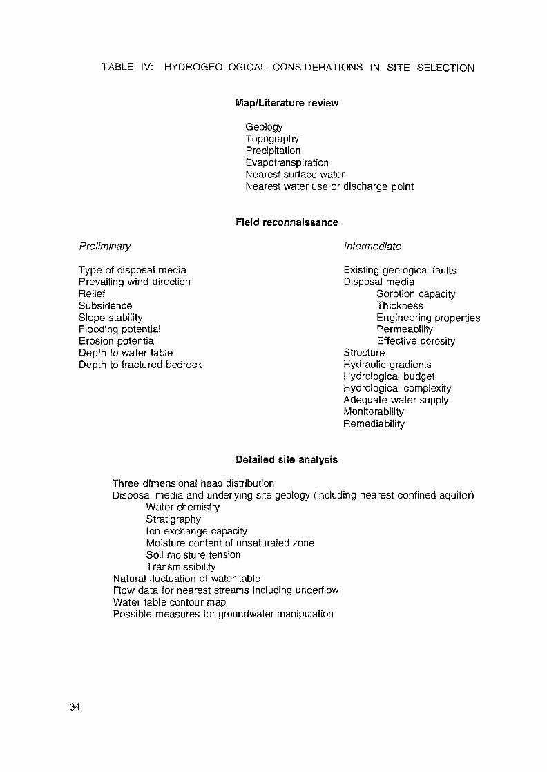
TABLE IV: HYDROGEOLOGICAL CONSIDERATIONS IN SITE SELECTION
Map/Literature review
GeologyTopographyPrecipitationEvapotranspirationNearest surface waterNearest water use or discharge point
Field reconnaissance
Preliminary Intermediate
Type of disposal media Existing geological faultsPrevailing wind direction Disposal mediaRelief Sorption capacitySubsidence ThicknessSlope stability Engineering propertiesFlooding potential PermeabilityErosion potential Effective porosityDepth to water table StructureDepth to fractured bedrock Hydraulic gradients
Hydrological budgetHydrological complexityAdequate water supplyMonitorabilityRemediability
Detailed site analysis
Three dimensional head distributionDisposal media and underlying site geology (including nearest confined aquifer)
Water chemistryStratigraphyIon exchange capacityMoisture content of unsaturated zoneSoil moisture tensionTransmissibility
Natural fluctuation of water tableFlow data for nearest streams including underflowWater table contour mapPossible measures for groundwater manipulation
34
(e) Determination of background radiation levels (done during the preliminary planning);
(f) The final survey to ensure compliance with release criteria;
(g) Documentation;
(h) A quality assurance programme which should ensure that the sampling, analysis, monitoring,documentation, interpretation, use of data, etc., would not result in the release of an areahaving activity levels greater than the designated criteria.
6.2. Costs and Number of Measurements
The cost of ensuring that areas, buildings, materials or equipment being released for reusecomply with release criteria can be highly variable and depends on many factors such as the type andsize of the component, the release criteria and labour and analytical costs.
Depending on factors such as future land use, population density, soil type, uniformity ofcontamination, type of topography and accessibility, and equipment availability, the number ofmeasurements required for verification may vary to a great extent.
Since the number of samples taken during the cleanup operations may be very large, statisticalsampling plans should be developed for various zones to minimize the number of samples requiredand increase the probability that unacceptable levels of contamination are not missed. This samplingplan should be backed up by an appropriate quality control programme. For measurement sets havinga large number of samples, the quality control programme, measurement validation function, type ofmeasurement, etc., would be strongly influenced by costs.
Depending on the intended use of a specific type of measurement, differing quality controlrequirements may be appropriate. For example, less stringent quality control need be applied to initialaerial survey data, since (for various reasons) interpretation of such measurements is difficult, andmeasurements are in general used either for preliminary direction of cleanup or for final checks ofcleanup effectiveness on a broad scale only. On the other hand, quality control for final surveys andfor sample and laboratory analyses, including sample preparation, should be stringent, since theinstruments are capable of good accuracy and the results could be critical for release of sites.
Selection of quality control criteria should be performed in advance, based on an evaluationof such factors as:
(a) Variation of the parameters being monitored;
(b) The purpose of the particular data set, for example for final dose estimates or preliminarygamma exposure estimates;
(c) The costs of sampling and the funding available.
To control costs and maintain adequate accuracy when quality control for a large number ofindividual measurements is required, a logical sequence of measurement quality control should beconsidered in advance. In general, only a small fraction of quality control is performed using expensivelaboratory chemical separation analysis. This level of quality control is used only as a final check onthe absolute accuracy of well designed field analytical systems, which in turn are used to regularlycorroborate inexpensive scan type systems that produce the vast majority of the cleanup measurements.
35
TECHNOLOGIES FOR RESTORATION OF ENVIRONMENTCONTAMINATED WITH RADIONUCIJDES IN BELARUS
G. SHAROVAROVAcademy of Sciences of Belarus,Minsk, Belarus
Abstract
The state of work on creation of technologies for clean-upof the territories of Belarus contaminated as a result of theChernobyl accident is considered in the report. It is pointed out,that the technologies for decontamination of pre-school medicaland prophylactical institutions, schools, zones for recreation,industrial and agricultural objects are used in Belarus.
On the whole, the strategy of changing the residence of popula-tion and supervision over the radiological situation is carriedout in the Republic.
Clean-up of contaminated soils of large territories is notrealized in the Republic on industrial scale.
Presently, the methods have been developed for radiation fore-cast and determination of advisable extent of decontamination.
The description of worked out technologies for decontaminaton,waste management and disposal is given. The need in developmentof industrial methods for the soil clean-up is shown.
There are about 1 million Curie of activity at the territory ofBelarus. Caesium - 137, strontium - 90, plutonium - 239, 240 arethe main contaminants. For the purpose of evaluating the level ofcontamination in Belarus/ the concept of density of contaminationhas been introduced. .This value defines the number ofdisintegrations on a unit area.
The territory of the Republic of Belarus is divided into someregions depending on density of contamination.The living conditionsand measures for decontamination have been developed for eachregion. The data on development of technologies fordecontamination of various surfaces during clean-up operations inBelarus are given in Table I. Three stages of work are consideredin it:
- scientific research;- experimental;- industrial.The main fraction of radionuclides is in soil, forest and water
ecosystems. The territories with high density of contaminationcause the greatest anxiety. Total volume of contaminated arableland, gardens, pastures accounts for 1.645 milliard cubic metres.The major proportion of them are radioactive wastes. Table II givesthe data on the volumes of the contaminated soil.
Up to now the large scale clean-up of the territories haven'tbeen carried out in Belarus.
Chemical and physical methods for decontamination procedures,which will be used for soil clean-up operations, are beingdeveloped under laboratory conditions. In 1995, it is intended todevelop the project on environmental restoration of contaminatedterritories jointly with French companies.
37
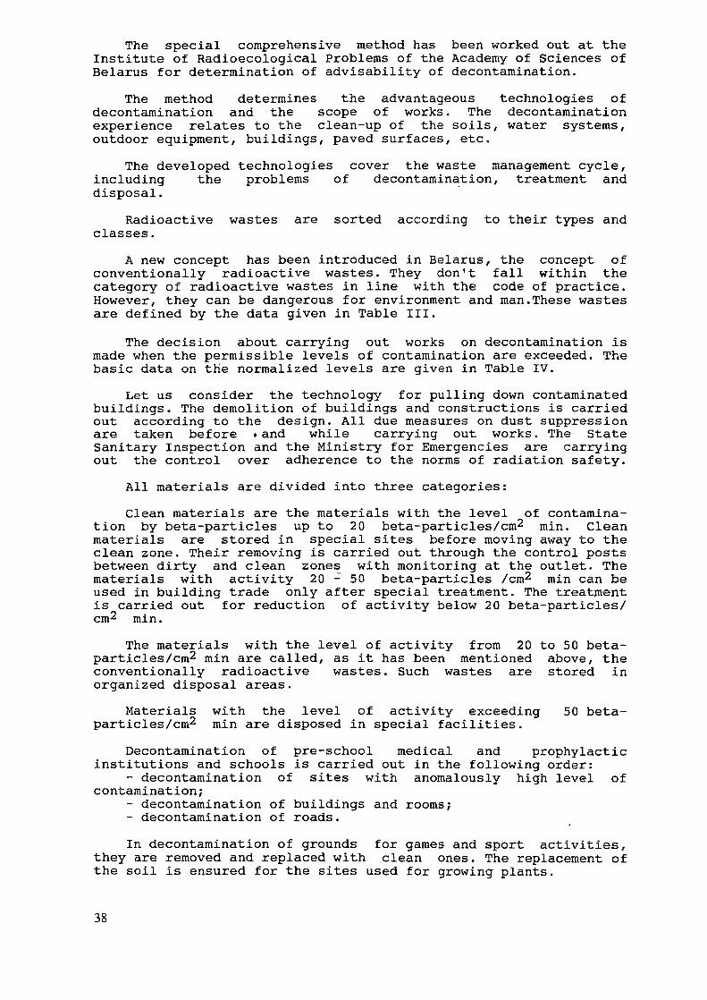
The special comprehensive method has been worked out at theInstitute of Radioecological Problems of the Academy of Sciences ofBelarus for determination of advisability of decontamination.
The method determines the advantageous technologies ofdecontamination and the scope of works. The decontaminationexperience relates to the clean-up of the soils, water systems,outdoor equipment, buildings, paved surfaces, etc.
The developed technologies cover the waste management cycle,including the problems of decontamination, treatment anddisposal.
Radioactive wastes are sorted according to their types andclasses.
A new concept has been introduced in Belarus, the concept ofconventionally radioactive wastes. They don't fall within thecategory of radioactive wastes in line with the code of practice.However, they can be dangerous for environment and man.These wastesare defined by the data given in Table III.
The decision about carrying out works on decontamination ismade when the permissible levels of contamination are exceeded. Thebasic data on the normalized levels are given in Table IV.
Let us consider the technology for pulling down contaminatedbuildings. The demolition of buildings and constructions is carriedout according to the design. All due measures on dust suppressionare taken before .and while carrying out works. The StateSanitary Inspection and the Ministry for Emergencies are carryingout the control over adherence to the norms of radiation safety.
All materials are divided into three categories:Clean materials are the materials with the level of contamina-
tion by beta-particles up to 20 beta-particles/cm2 min. Cleanmaterials are stored in special sites before moving away to theclean zone. Their removing is carried out through the control postsbetween dirty and clean zones with monitoring at the outlet. Thematerials with activity 20 - 50 beta-particles /cm2 min can beused in building trade only after special treatment. The treatmentis carried out for reduction of activity below 20 beta-particles/cm2 min.
The materials with the level of activity from 20 to 50 beta-particles/cm2 min are called, as it has been mentioned above, theconventionally radioactive wastes. Such wastes are stored inorganized disposal areas.
Materials with the level of activity exceeding 50 beta-particles/cm2 min are disposed in special facilities.
Decontamination of pre-school medical and prophylacticinstitutions and schools is carried out in the following order:
- decontamination of sites with anomalously high level ofcontamination;
- decontamination of buildings and rooms;- decontamination of roads.In decontamination of grounds for games and sport activities,
they are removed and replaced with clean ones. The replacement ofthe soil is ensured for the sites used for growing plants.
38
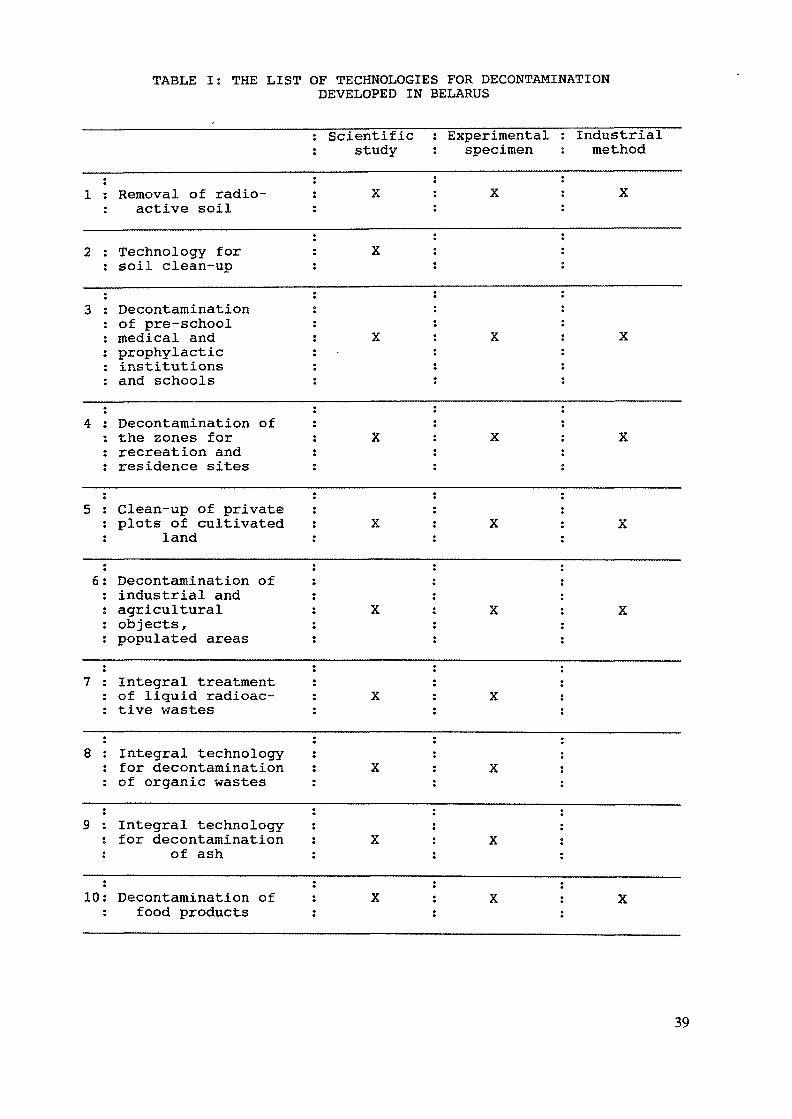
TABLE I: THE LIST OF TECHNOLOGIES FOR DECONTAMINATIONDEVELOPED IN BELARUS
1
2
3
4
5
6
7
8
9
10
t
: Removal of radio-: active soil
Technology forsoil clean-up
Decontaminationof pre-schoolmedical andprophylacticinstitutionsand schools
Decontamination ofthe zones forrecreation andresidence sites
Clean-up of privateplots of cultivated
land
Decontamination ofindustrial andagriculturalobjects,populated areas
Integral treatmentof liquid radioac-tive wastes
Integral technologyfor decontaminationof organic wastes
Integral technologyfor decontamination
of ash
Decontamination offood products
scienriricstudy
X
X
X
X
X
A
X
X
X
X
isxperimentaj.specimen
X
X
X
X
X
X
X
X
X
inaustricu.method
X
X
X
X
X
X
39
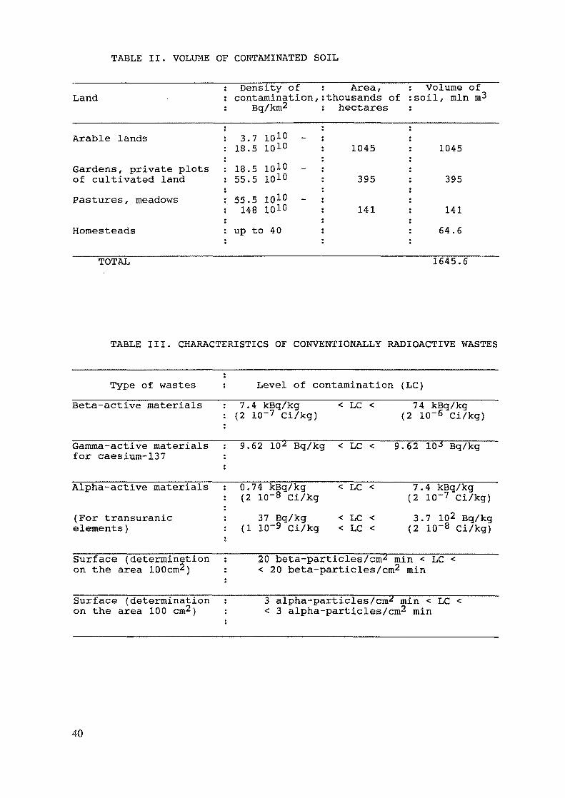
TABLE II. VOLUME OF CONTAMINATED SOIL
Land
Arable lands
Gardens, private plotsof cultivated landPastures, meadows
Homesteads
Density ofcontamination ,
Eg/km2
3.7 1010 -18.5 1010
18.5 1010 -55.5 1010
55.5 1010 -148 ID1*)
up to 40
Area,thousands ofhectares
1045
395
141
Volume ofsoil, mln m^
1045
395
14164.6
TOTAL 1645.6
TABLE III. CHARACTERISTICS OF CONVENTIONALLY RADIOACTIVE WASTES
Type of wastesBeta-active materials
Gamma-active materialsfor caesium-137
Alpha-active materials
(For transuranicelements )
Surface (determinetionon the area 100cm2)
Surface (determinationon the area 100 cm2}
Level of contamination (LC)7.4 kBq/kg < LC < 74 kBq/kg(2 10~7 Ci/kg) (2 10~6 Ci/kg)
9.62 10^ Bq/kg < LC < 9.62 10 J Bq/kg
0.74 kBq/kg < LC < 7.4 kBq/kg(2 10~8 Ci/kg (2 10~7 Ci/kg)
37 Bq/kg < LC < 3.7 102 Bq/kg(1 10~9 Ci/kg < LC < (2 10~8 Ci/kg)
20 beta-particles/cm^ min < LC << 20 beta-particles/cm2 min
3 alpha-part icles/cm-^ min < LC << 3 alpha-particles/cm2 min
40
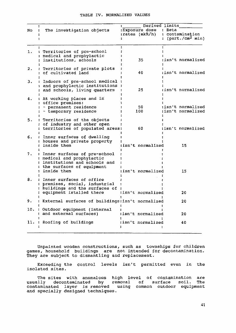
TABLE IV. NORMALIZED VALUES
No The inve'stigation objectsDerived limits
Exposure doserates (rakR/h)
Betacontamination(part./cm min)
1.
2.
3.
4.
5.
6.
7.
8.
9.10.
11.
Territories of pre-schoolmedical and prophylacticinstitutions, schoolsTerritories of private plotsof cultivated landIndoors of pre-school medicaland prophylactic institutionsand schools, living quartersAt working places and inoffice premises:- permanent residence- temporary residenceTerritories of the objectsof industry and other openterritories of populated areasInner surfaces of dwellinghouses and private propertyinside themInner surfaces of pre-schoolmedical and prophylacticinstitutions and schools andthe surfaces of equipmentinside themInner surfaces of officepremises, social, industrialbuildings and the surfaces ofequipment istalled thereExternal surfaces of buildingsOutdoor equipment (internaland external surfaces)Roofing of buildings
35
40
25
50100
60
isn't normalized
isn't normalized
isn't normalized
isn't normalizedisn't normalized
isn't normalized
isn't normalizec 15
isn't normalized
isn't normalizedisn't normalized
isn't normalizecisn't normalized
15
2020
2040
Unpainted wooden constructions, such as townships for childrengames, household buildings are not intended for decontamination.They are subject to dismantling and replacement.
Exceeding the control levels isn't permitted even in theisolated sites.
The sites with anomalous high level of contamination areusually decontaminated by removal of surface soil. Thecontaminated layer is removed using common outdoor equipmentand specially designed techniques.
41
Decontamination of the zones for recreation and the peopleresidence sites is carried out in two stages:
- decontamination of anomalous spots with high activity;- decontamination of the entire site.With low levels of activity, the overlaying the soil with clean
topsoil can be used, followed by sowing the perennial plants.Decontamination of household sites is carried out in three
stages:- decontamination of anomalous spots with high activity;- decontamination of household buildings;- decontamination of private plots of cultivated land.The household buildings are completely demolished, if wooden,
porous blocks and asbestos cement have been used as buildingmaterials.
In the places of domestic animals maintenance, the completeremoval of manure and the under-layer is made.
When realizing the works, separate collection of liquid andsolid wastes generated in decontamination is arranged. Liquidwastes are collected into leak-tight reservoirs and sent fortreatment. Solid wastes are graded into three types:
- domestic wastes;- conventinally radioactive wastes;- radioactive wastes.The following measures are foreseen for prevention of the
secondary contamination:- the works are carried out in dry windless weather;- the wastes are collected at the end of each day;- wastes are transported skirting the populated areas.In the process of work the DRGZ - O.2, DRG - 01T1, DRG - 05,
DVG - 06T devices are used for measurement of the dose rate.The MKS 01P1 radiometer - dosimeter and the universal RUP - 1
radiometer are used for measurement of beta - particle densities.For decontamination of places with hard covering, sweeping,
high pressure jetting from the firehosing are applied.The removal of the soil is primarily practised for
decontamination of surfaces without hard coverings.Decontamination of industrial and agricultural enterprises
begins with anomalously contaminated sites.Decontamination of the spots at the sites with hard coverings
is implemented by simple mechanical cleaning and surfactants. Whenthere is no results, mechanical stabilizers are used to physicallycover the contamination. They include concrete and asphaltprotective covers. Decontamination of spots at the sites withouthard coverings is executed by removal of the contaminated spot.The isolation of the spot is admitted as an exception.
Decontamination of equipment is performed as follows:- mechanical removal of radioactive dust;- decontamination of the outer surface;- decontamination of separate components in special bathes.If the permissible levels of contamination are not achieved
after decontamination is carried out three times, the decision ismade about the replacement of equipment.
42
Technological process of decontamination of machineryis conducted in two stages:- removal of oils and soil with the help of brushes andscrapers;- removal of contamination using decontaminating solutions.
In order to decontaminate rubber, decontamination is carriedout two times:
- 5 % soda solution; 0.1 % potassium permanganate and 0.4 %potassium hexametaphosphate;
- 2 % nitric acid solution, 0.2 % oxalic acid, 0.2 % sodiumfluoride and 0.5 % detergents.
Decontamination of the ventilation systems of industrialenterprises is carried out with the help of decontaminatingsolutions. Decontamination of heaters in ventilation chambers isaccomplished by steam with addition of surfactants. Table Vsummarizes the recommended detergents for decontamination ofequipment surfaces, machinery and ventilation systems.
Presently, paste-like compositions are prepared fordecontamination of contaminated metal unpainted surfaces. Theymake it possible to remove 93 - 97 % of caesium-137 and 83 - 95 %of strontium-90.
The data for painted surfaces are 91 - 95 % and 79 - 95 %,correspondingly.
The efficiency of decontamination substantially depends on thedeadline of putting the equipment in dead storage. When this dateis 5 - 10 days, the total reduction of activity is 95 %. With thedeadline equal to 5 - 6 monthes, the reduction is only 35 %. Inaddition, it has been established, that the waste water is notcontaminated with radionuclides.
In the process of decontamination, liquid and solidradioactive wastes are generated.
In the Institute of Radioecological Problems of the Academy ofSciences of Belarus two installations have been designed fortreatment of liquid radioactive wastes.
The first installation is operated on the principle ofchemical co-precipitation followed by separation of solid andliquid phases.
The second installation takes as the basis the evaporation ofrotatable liquid flow.
The process of volumetric evaporation is carried out in thisapparatus. Liquid is preheated and then the evaporation of whirledliquid occurs, when pressure is reduced. It should be noted, thatsuch eddy evaporator is the separator at the same time. Itdecontaminates liquid radioactive wastes of any composition.
Fig. 1 gives the basic elements of the installation forprocessing liquid radioactive wastes. The installation embodiesthe following principle:
Liquid is heated and conveyed by the tangential channel intothe evaporation chamber. On the certain radius of rotation liquidcomes to the boil. Vapour bubbles move to the axis of theevaporator with the velocity 10-20 m/sec and liquid moves to
43
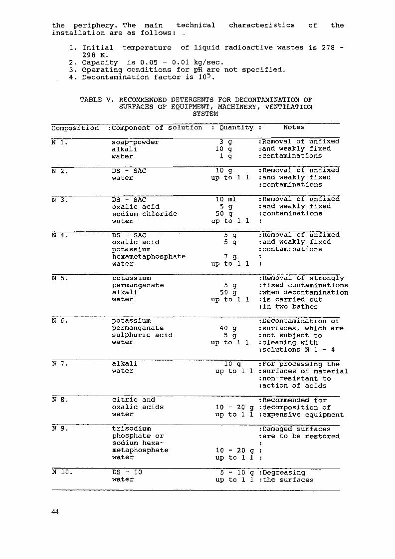
the periphery. The main technicalinstallation are as follows: -
characteristics of the
2.3.
Initial temperature of liquid radioactive wastes is 278 -298 K.Capacity is 0.05 - 0.01 kg/sec.Operating conditions for pH are not specified.
4. Decontamination factor is
TABLE V. RECOMMENDED DETERGENTS FOR DECONTAMINATION OFSURFACES OF EQUIPMENT, MACHINERY, VENTILATION
SYSTEM
CompositionN I.
N 2.
N 3.
N 4.
N 5.
N 6.
N 7.
N 8.
N 9.
N 10.
: Component of solutionsoap-powderalkaliwaterDS - SACwater
DS - SACoxalic acidsodium chloridewaterDS - SACoxalic acidpotassiumhexametaphosphatewaterpotassiumpermanganatealkaliwater
potassiumpermanganatesulphuric acidwater
alkaliwater
citric andoxalic acidswatertrisodiumphosphate orsodium hexa-metaphosphatewaterDS - 10water
: Quantity3 g10 gi g10 g
up to 1 1
10 ml5 g50 g
up to 1 15 g5 g7 gup to 1 1
5 g50 g
up to 1 1
40 g5 g
up to 1 1
10 gup to 1 1
10 - 20 gup to 1 1
10 - 20 gup to 1 15 - 10 g
up to 1 1
: Notes: Removal of unfixed:and weakly fixed: contaminations: Removal of unfixed:and weakly fixed: contaminations: Removal of unfixedsand weakly fixed: contaminations«
: Removal of unfixed: and weakly fixed: contaminations••
: Removal of strongly: fixed contaminations:when decontamination:is carried out; in two bathes: Decontamination of: surf aces, which are:not subject to: cleaning with: solutions N 1 - 4:For processing the: surf aces of material: non-resistant to: action of acids: Recommended for: decomposition of: expensive equipment: Damaged surfaces:are to be restored»9
•
*•
:Degreasing:the surfaces
44
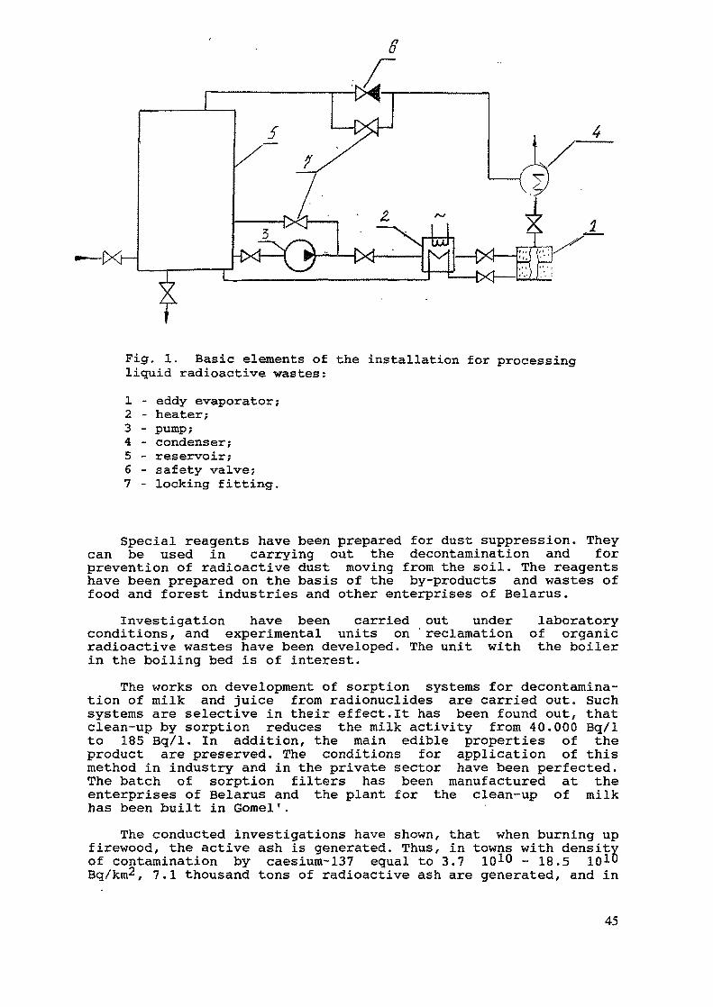
•—IXH
Fig. 1. Basic elements of the installation for processingliquid radioactive wastes:1 - eddy evaporator;2 - heater;3 - pump;4 - condenser;5 - reservoir;6 - safety valve;7 - locking fitting.
Special reagents have been prepared for dust suppression. Theycan be used in carrying out the decontamination and forprevention of radioactive dust moving from the soil. The reagentshave been prepared on the basis of the by-products and wastes offood and forest industries and other enterprises of Belarus.
Investigation have been carried out under laboratoryconditions, and experimental units on 'reclamation of organicradioactive wastes have been developed. The unit with the boilerin the boiling bed is of interest.
The works on development of sorption systems for decontamina-tion of milk and juice from radionuclides are carried out. Suchsystems are selective in their effect.It has been found out, thatclean-up by sorption reduces the milk activity from 40.000 Bq/1to 185 Bq/1. In addition, the main edible properties of theproduct are preserved. The conditions for application of thismethod in industry and in the private sector have been perfected.The batch of sorption filters has been manufactured at theenterprises of Belarus and the plant for the clean-up of milkhas been built in Gomel'.
The conducted investigations have shown, that when burning upfirewood, the active ash is generated. Thus, in towns with densityof contamination by caesium-137 equal to 3.7 1010 - 18.5 101DBg/km^, 7.1 thousand tons of radioactive ash are generated, and in
45
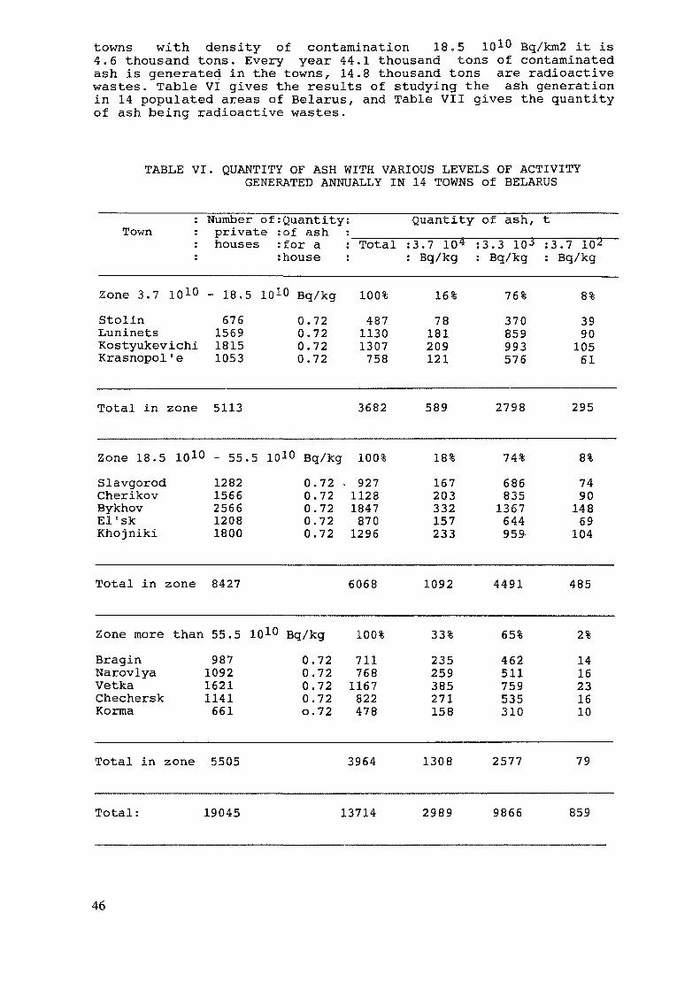
towns with density of contamination 18.5 10^ Bq/km2 it is4.6 thousand tons. Every year 44.1 thousand tons of contaminatedash is generated in the towns, 14.8 thousand tons are radioactivewastes. Table VI gives the results of studying the ash generationin 14 populated areas of Belarus, and Table VII gives the quantityof ash being radioactive wastes.
TABLE VI. QUANTITY OF ASH WITH VARIOUS LEVELS OF ACTIVITYGENERATED ANNUALLY IN 14 TOWNS of BELARUS
Town: Number of: Quantity:: private :of ash :: houses : for a : Total: : house :
Quantity of ash, t:3.7 10* :3.3 10-* :3.7 10: Bq/kg : Bq/kg : Bq/kg
Zone 3.7 1010 - 18.5Stolin 676Luninets 1569Kostyukevichi 1815Krasnopol'e 1053
Bq/kg 100%0.720.720.720.72
48711301307758
16%78181209121
76%370859993576
8%3990
10561
Total in zone 5113 3682 589 2798 295
Zone 18.5 1010 - 55.5 1010 Bq/kg 100%SlavgorodCherikovBykhovEl'skKhojniki
12821566256612081800
0.720.720.720.720.72
92711281847870
1296
18%167203332157233
74%6868351367644959
8%749014869104
Total in zone 8427 6068 1092 4491 485
Zone more than 55.5 1010 Bq/kgBraginNarovlyaVetkaChecherskKorma
987109216211141661
0.720.720.720.720.72
100%7117681167822478
33%235259385271158
65%462511759535310
2%1416231610
Total in zone 5505 3964 1308 2577 79
Total: 19045 13714 2989 9866 859
46
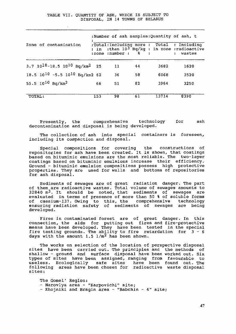
TABLE VII. QUANTITY OF ASH, WHICH IS SUBJECT TODISPOSAL, IN 14 TOWNS OF BELARUS
Zone of contamination:Number of ash samples:Quantity of ash, t:Total:Including more : T o t a l : Including: in :than 10^ Bq/kg : in zone :radioactive:zone :number : % : : wastes
3.7 1010-18.5 1010 Bq/km2 2518.5 1010 -5.5 1010 Bq/km2 6255.5 1010 Bq/km2 66
113651
445882
368260683964
162035203250
TOTAL: 153 98 61 13714 8390
Presently, the comprehensive technologydecontamination and disposal is being developed.
for ash
The collection of ash into specialincluding its compaction and disposal.
containers is foreseen,
Special compositions for covering the constructions ofrepositories for ash have been created. It is shown, that coatingsbased on bituminic emulsions are the most reliable. The two-layercoatings based on bituminic emulsions increase their efficiency.Ground - bituminic emulsion compositions possess high protectiveproperties. They are used for walls and bottoms of repositoriesfor ash disposal.
Sediments of sewages are of great radiation danger. The partof them are radioactive wastes. Total volume of sewages amounts to32840 m3. It should be noted, that sediments of sewages areevaluated in terms of presence of more than 50 % of soluble formsof caesium-137. Owing to this, the comprehensive technologyensuring radiation safety of sediments of sewages are beingdeveloped.
Fires in contaminated forest are of great danger. In thisconnection, the aids for putting out fires and fire-protectivemeans have been developed. They have been tested in the specialfire testing grounds. The ability to fire retardation for 3-6days with the amount 1.5 1/m2 has been shown.
The works on selection of the location of perspective disposalsites have been carried out. The principles and the methods ofshallow - ground and surface disposal have been worked out. Sixtypes of sites have been assigned, ranging from favourable touseless. Ecologically safe sites have been found out. Thefollowing areas have been chosen for radioactive waste disposalsites:
The Gomel' Region:- Narovlya area - "Karpovichi" site;- Khojniki and Bragin area - "Babchin - 4" site;
47
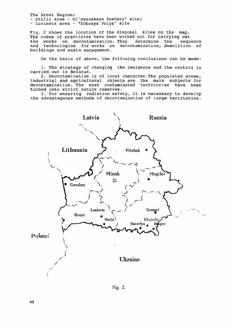
The Brest Region:- Stolin area - Ol'myanskaya Koshara" site;- Luninets area - "Dobraya Volya" siteFig. 2 shows the location of the disposal sites on the map.The codes of practicies have been worked out for carrying outthe works on decontamination. They determine the sequenceand technologies for works on decontamination, demolition ofbuildings and waste management.
On the basis of above, the following conclusions can be made:1. The strategy of changing the residence and the control is
carried out in Belarus.2. Decontamination is of local character.The populated areas,
industrial and agricultural objects are the main subjects fordecontamination. The most contaminated territories have beenturned into strict nature reserves.
3. For ensuring radiation safety, it is necessary to developthe advantageous methods of decontamination of large territories.
Latvia Russia
Poland
Ukraine
Fig. 2.
48
REFERENCES
[1] SHAROVAROV, G.A., BYKOV, A.I., VERETENNIKOV, V.G., YATSKO,S.N.,Decontamination of the Territories of Belarus Contaminatedwith Radiohuclides as a Result of the Accident at the ChernobylNPP, Academy of Sciences, Preprint of IREP, Minsk (1994).
[2] SHAROVAROV, G.A., Problems of Environmental Restoration of theTerritories of Belarus Contaminated as a Result of theChernobyl Accident, Academy of Sciences, Preprint of IREP,Minsk (1992).
[3] SHAROVAROV, G., MILLIGAN, J.,BUONI, A., Contamination of theTerritory of Belarus as a Result of the Chernobyl Accident,NAER(Proc.18-th Annual Conference), North Carolina, USA(1993).
[4] The Trace of Chernobyl in Belarus, Minsk (1992).[5] GORBACHEV, B. I., GOTOVCHITS,G.I., OGORODNIK,S.S. , SHAROVAROV, G. A.
Problems and Perspectives of Mitigation of the Consequences ofthe Chernobyl Accident, Academy of Sciences, Preprint of IREP,Minsk (1990).
[6] DAVYDOVA, Zh.V., MOROZOV, S.V., SHAROVAROV, G.A., Methods ofMathematical Modelling of Distribution of RadioactiveDischarges of Nucler Power Plants, Academy of Sciences,Preprint of IREP, Minsk (1990).
[7] Agricultural Radioecology (ALEKSAKHIN,R.M., KORNEEVA,N.L. ,Ed.) ,Ecology, Moscow (1992).
[8] SOBOLEV, I.A., KORENKOV, I.P, KHOMICH, P.M., PROKAZOVA, L.M.,Environmental Protection in Management of Radioactive Wastes,Ecology, Moscow (1989).
[9] CHIRKET, D.Eh., CHALIYAN, K.N. , CHALIYANI, A.G., et al.,Investigations on Decontamination of Soils of Private Plotsfrom Caesium-137 Radionuclides at the Territory of NovozybkovArea of Bryansk Region, (International Seminar "Experiencein Remediation of the Territories Suffering as a Result ofthe Chernobyl Accident", Novozybkov, 30 November - 2 December,1993), Report (1994).
[10] AKINFIEV, V.P., Efficiency and Methods of Engineering Deconta-mination of Territories (Int. Syrup, on Remediation and Restora-tion of Radioactively Contaminated Sites in Europe, Belgium),Book of Abstracts (1993).
[11] Regulations on Decontamination and Management of Wastes, Gene-rated as a Result of Works on Elimination of the Consequencesof the Chernobyl Accident, Minsk (1992) 12 p.
[12] The Temporary Schedule on Decontamination of Populated Areas,Buildings, Pre-School Medical and Prophylactic Institutions,Schools and other Civil Organizations, Minsk (1993) 22 p.
[13] Methodologies on Management of Wastes, Generated in the Processof Demolition of Buildings and Constuctions in the Zone ofChanging the Residence, Minsk (1994) 11 p.
[14] The Temporary Schedule on Demolition and Disposal of Buildingsand Constructions in the Zones of Evacuation (Alienation) andChanging the Residence, Minsk J1992) 18 p.
[15] The Temporary Schedule on the Control over the Sites for Dispo-sal of Wastes, Generated in the Process of Decontamination andEnsuring Safety in Carrying out the Works, Minsk (1993) 14 p.
49
URANIUM INDUSTRY IN BULGARIA AND ENVIRONMENT:TECHNOLOGIES AND IMPLEMENTATION OFENVIRONMENTAL RESTORATION PROJECTS
M. DIMITROVNuclear Power Plant at Kozloduy, Kozloduy
E.I. VAPIKEV, L. MINEV, T. BOSHKOVAFaculty of Physics, Sofia University, Sofia
Bulgaria
Abstract
The paper presents a summary of the environmental restoration process in Bulgaria before thetermination of the uranium industry (August 1992) when some sites due to depletion had beenclosed and also the restoration procedure which are currently applied. The methods forrehabilitation depend on the type of site and therefore the uranium mines, the milling plantsand the auxiliary units are discussed separately. At present all sites have been ecologicallyassessed and for most of them the restoration technologies are selected. Part of the land isrestored and returned to its owners. For the in-situ leaching sites long term monitoring ofunderground water is necessary. The restoration activities must be synchronized since residualore has to be processed and waste has to be dumped in tailing ponds and underground mines.It has been pointed out that there is a need for cheap and proven technologies since the closeduranium industry has to provide the funding for the restoration process and there aredifficulties due to the general reduction of industrial production in the country.
1.Introduction - review of the uranium industry in Bulgaria [1,2]
The uranium industry in Bulgaria started immediately after the II World War withclassical underground mining and hydrometalurgical processing of the ore to uraniumconcentrate. The total amount of uranium concentrate produced in the period 1947-1992 is approximately 35000 t or 800 t/annually in the last years before the closure ofthe uranium industry.Approximately 34 uranium mining sites exist which include 4 open pit mines, under-ground mines and in situ-leaching mines (after 1968-69).
The total amount of tailing pond wastes of the two milling plants in Buhovo andEleshnitsa (3 tailings) is 16 000 000 t and approximately 3.1 PBq of stored activity.The total number of the waste heaps is 298 with approximately 13 720 000 t ofdumped mass which covers approximately 845 000 square meters.
Up to 1958 no tailings pond existed at the Buhovo plant and the result is 1 200 000square meters contaminated with radium land along the rivers Yanishtitsa andLesnovska.
Along the valleys of the rivers Maritsa, Tundzha and Struma approximately 15 lowgrade ore deposits were processed by in-situ leaching with sulfuric acid. The surfacecommunications (tubes) cover approximately 16 000 000 m2 agricultural land and for-ests. Some of the heaps of the underground mines have been processed by combinedin-situ leaching technologies.The total contaminated area affected by the uranium industry is approximately 20 000 000 m2,including 4 000 000 m2 forest.
51
At present the uranium industry is terminated by a government decision and the necessaryfunding for restoration of the former uranium sites is expected to be raised by selling ofequipment.
2.Technologies and procedures for environmental restoration applied before the termina-tion of the uranium industry.
A number of uranium sites were closed before the decision for total termination of the ura-nium industry (see Table 1 in [1] ). Many mines have been closed in the Buhovo region,mines near the towns of Sliven and Melnik, near the Haskovo mineral baths, above the Rilamonastery. In-situ leaching sites have been also closed - near the village of Prepechene andZlatolist in South-West Bulgaria (along the Struma river), some sites of the mine "Pioneer"near the village of Orlov dol and also sites in the Upper Tracian Plane.
A common feature for all sites is that no environment remediation actions followed after thetechnical closure. In some cases the monitoring had also been terminated. The environmentalmonitoring was resumed within the procedures for radioecological assessment and decisiontaking for site remediation.
The only procedure which has been in implementation is the closure of the entrances ofshafts and adits but long afterwards poorly closed exits used to emerge as caving or downfallsoccurred.There are still abandoned trolleys, broken equipment, repair shops, administrative buildings.Only some reloading sites being close to railroad stations have been cleaned-up.
The operation of the first tailing pond of the Buhovo plant has been terminated long beforethe closure of the uranium industry but no actions followed - no fence was built and it oftenserved as pasture ground for cattle. The migration of water due to tailing seepage is con-trolled by regular sampling of water in control shafts down the tailing pond. Control of thewater is necessary since no tailing impoundment (liners, cover layers) had been implementedwhen the pond was built.
No water treatment facility has been built after the closure of any site, no actions were takenagainst wind and sheet and rill erosion of the waste heaps. Only some sorption facilities forexcess water have been used during the operation of several mines in order to extract theuranium from water which otherwise will be lost ("Deveti septemvri", "Druzhba", "Dospat" ).
In the period 1985-1990 remediation procedures were applied for closed sites of the mine"Pioneer" according to a method developed in the Institute of Soil "N.Pushkarov" (Sofia).The method is intended for a period of approximately 5 y and includes radioecological survey,cleaning-up, neutralization, intensive natural fertilization.
Before the termination of the uranium industry a project was started for restriction of thepropagation of the contaminated underground water of sites "Okop" and "Tenevo" (mine"Pioneer") and site "Cheshmata" (Mine "Parvi mai"). The project has been developed in theformer USSR and included pumping of chemical agents - e.g. sodium silicate solution(soluble glass) around a leaching site in order to "seal" the underground contaminated water.The project was not realized , only some preliminary experimental observations can beused for further estimation for the migration velocity of contaminated water.
S.Technologies for environmental restoration applied after the total termination of the urani-um industry.
At present all uranium industry sites are radioecologically assessed and most of summaryinformation was reported in the previous meetings [1,2].
52
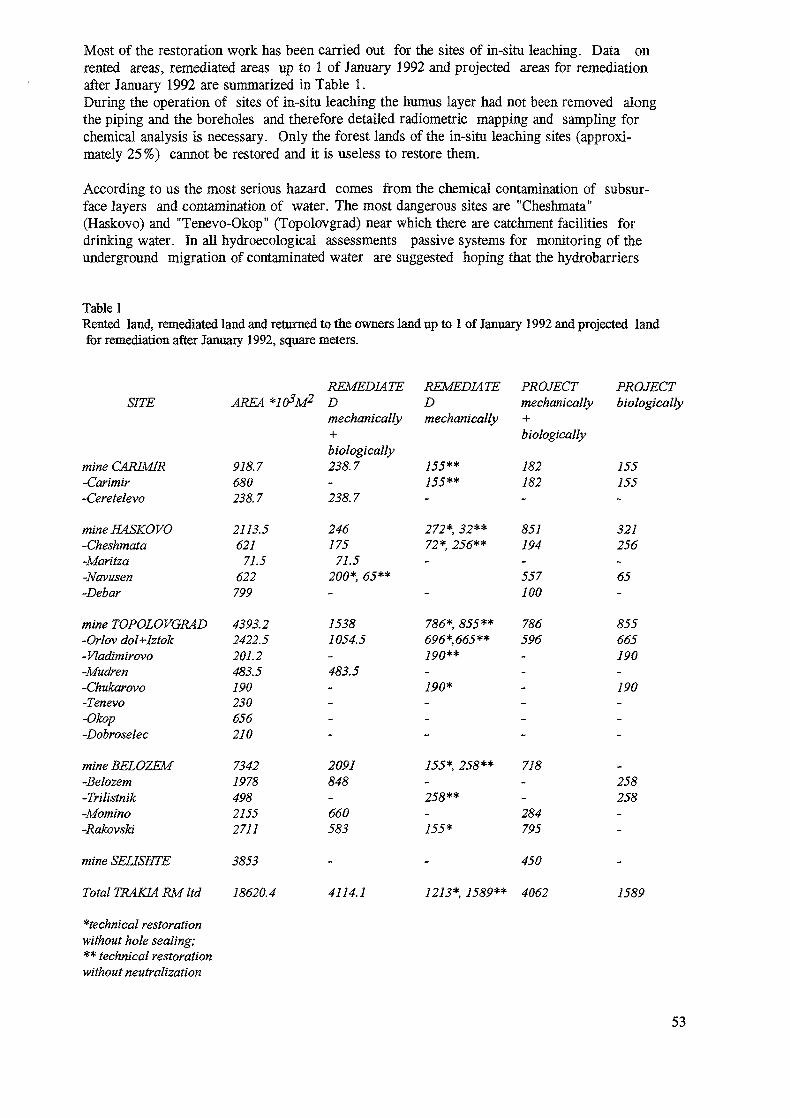
Most of the restoration work has been carried out for the sites of in-situ leaching. Data onrented areas, remediated areas up to 1 of January 1992 and projected areas for remediationafter January 1992 are summarized in Table 1.During the operation of sites of in-situ leaching the humus layer had not been removed alongthe piping and the boreholes and therefore detailed radiometric mapping and sampling forchemical analysis is necessary. Only the forest lands of the in-situ leaching sites (approxi-mately 25%) cannot be restored and it is useless to restore them.
According to us the most serious hazard comes from the chemical contamination of subsur-face layers and contamination of water. The most dangerous sites are "Cheshmata"(Haskovo) and "Tenevo-Okop" (Topolovgrad) near which there are catchment facilities fordrinking water. In all hydroecological assessments passive systems for monitoring of theunderground migration of contaminated water are suggested hoping that the hydrobarriers
Table 1Rented land, remediated land and returned to the owners land up to 1 of January 1992 and projected landfor remediation after January 1992, square meters.
SITE
mine CAJRIMR-Carimir-Ceretelevo
mine HASKOVO-Cheshmata-Maritza-Navusen-Debar
mine TOPOLOVGRAD-Orlav dol+htok-Vladimirovo-Mudren-Chukarovo-Tenevo-Okop-Dobroselec
mineBELOZEM-Belozem-Trilistnik-Momino-RakovsTd
mine SEHSHTE
Total TRAKIARM ltd
technical restoration'without hole sealing;-* technical restorationwithout neutralization
REMEDIATEAREA *103M2 D
mechanically
918.7680238.7
2113.5621
71.5622799
4393.22422.5201.2483.5190230656210
7342197849821552711
3853
18620.4
biologically238.7
238.7
REMEDIATEDmechanically
755**755**
75387054.5
483.5
786*, 855**696*,665**190**
190*
2091848
660583
4114.1
PROJECTmechanically+biologically
182182
246175
71.5200*, 65**
272*, 32**72*, 256**-
851194-557100
786596
PROJECTbiologically
155155
321256
65
855665190
190
155*, 258** 718
258**284
155* 795
450
1213*, 1589** 4062
258258
1589
53
will seal the water layer and consequently the contaminated water will be desalted. We arealso afraid that the calculated rates of migration are optimistic although we understand thatconstruction of adequate purification facilities for enormous water volumes is very expensiveand there are no sound arguments that they are absolutely necessary.
Data on quantity of uranium and specific activity of radium in water from different mines(Table 2) show that uranium is below the accepted limit for surface water (0.6 mg/1) but theactivity of Ra is generally above the limit (0.15 Bq/1). Continuous observations show that sev-eral years after the termination of mining there is a trend for water purification and Ra re-duction since Ra is transported by the mechanical particles.
At the present moment (end of 1994) two projects are being financially supported within thePHARE programme - restoration of the tailing pond region of Eleshnitsa and restoration of theBay of Vromos radioactively contaminated by dumping of slurry of copper mines [1]. Theprojects are in very initial stages and neither the methods nor the organization which will per-form the restoration have been selected.
Table 2Content of uranium, mg/1, and specific activity of radium, Bq/1, in uranium mine waste water
mine N*Deveti spetemvri 25Seslavtsi 24Smolyan 22Eleshnitsa 19Dospat 20Selishte 19Sliven 18Melnik 11N* - number ofsamples
A small experimental facility for bacterial sulfate reduction for the excess water from the tail-ing pond in Buhovo is now in the process of construction [3]. The bacterial removal of sul-fates from the washwater results also in simultaneous precipitation of heavy metals.
There are also other propositions but a major obstacle is the lack of financing.Another major obstacle for accurate assessment of the impact of radioactive contamination isthe lack of national levels for natural radionuclides in soil, plants and animal products. Onlylately such a project is under development - development of levels and criteria for protec-tion of the population which live in regions with increased natural radioactivity.
4.Technologies for environmental restoration of uranium mining and milling sites
The methods for rehabilitation depend on the type of site and therefore the uranium mines,the milling plants and the auxiliary objects will be discussed separately. All methods whichare implemented or are intended to be implemented are "classical" and described in earlierpublications [4,5]
The restoration activities must be synchronized since:all existing ore and ion-exchange resins have to be processed in the milling plants;radioactive waste has to be dumped in tailing ponds;part of the mined rock and equipment can be dumped in underground mines before seal-ing.
uranium,min0.040.010.030.020.020.040.010.01
mg/lmax0.371.050.971.120.430.800.370.97
average0.190.200.340.310.120.140.100.26
N*121216988137
radium^Bq/lmin525921185999.3140.6344203.5
max51431628
1320920460
632718315260858584
average1162696
35377130189880955990
270
54
4.1. Uranium mines - -underground mines, open pit mines, in-situ leaching sites.4.1.1. Underground mines.
The methods for restoration include:closure of adits, shafts, ventilation shafts;transportation of mined ore (if any) to the chemical plants;water precipitation or purification,;heap stabilization , leveling and afforestation., or leveling , isolation and afforestation.In the case of heap leaching , a neutralization is necessary;ban on house building on the heaps, prevention on the use of rock material for use inbuildings, especially for houses for living, possible use as rock for roads.
There are different alternatives for heap stabilization. For the isolation technologies becauseof the large total area (845 000 m2) the experts are looking for cheaper covering materialwhich has been experimentally verified.
4.1.2. Open-pit mines.
The methods for restoration include:site leveling, filling when possible;treating of the water collected in the region - precipitation or purification;ban on house building,use of the pit, if possible, for lake for recreation activities.
4.1.3.In-situ leaching sites
The main method for leaching in Bulgaria is the acid method, the soda methods had beenapplied only in experiments. For the in-situ leaching additional reagents have been used forintensification of the process - iron sulfide, potassium permanganate, sodium nitrite. Somemetals - Mo, Cu, Zn, Ni, W, Cr, Fe, Al, V, and also rare earths - La, Ce, Yb, are alsopresent in the solutions.
The methods for restoration include mechanical and biological technologies:removal of radioactive wastes of contaminated earth;deep sealing of boreholes in order to prevent direct water contact;neutralization of the contaminated with acid or soda areas (liming);leveling and intensive fertilization with natural fertilizer;"green" fertilization - ploughing of lucerne etc. before ripening;crop rotation, e.g. corn-rye-sunflower-rye etc.;drying or irrigation;grass, or planting fruit trees;
The methods for water restoration include:recycling of the solution for increasing the pH;neutralization of the water in the layer or on the surface;salt purification;generation of hydrochemical barriers;control of the eventual spread of contamination;ban on hole drilling for irrigation or drinking water.
4.2.Uraniwn milling plants.
The milling plants process ore and the ion exchange resins from the in-situ leaching sites.The wastes - slurry and water are deposited in the tailing ponds. The rehabilitation pro-cedures concern the plant site and the tailing pond. For the specific case of the Buhovo
55
plant, the Yana-Bogrov region needs remediation and counter-measures because of the con-tamination of large areas with Ra [1].
The methods for restoration of the plant site include:cleaning-up of the radioactive wastes and dumping the wastes in the tailing pond;deactivation of the plant premises;disassembling of filters, mills, transport belts etc.;
The methods for restoration of the tailing pond include:strengthening of the tailing dam wall;routing of the clean water away from the tailing pond;covering the pond with a layer for prevention of radon exhalation - clay, asphalt, poly-mers;covering the isolation layer with soil;planting of grass or trees;management of the tailing seepage of surface or underground water - neutralization (ifnecessary), purification for sulfates, heavy metals, radium;creation of a system for long term monitoring.
The methods for restoration of the radium contaminated areas of the Yana, Gorni Bogrov,Dolni Bogrov region [1 ] include:
removal of the most radioactive spots;afforestation of the contaminated areas;covering with soil of tailing pond wastes;control of utilization of the low contaminated areas.
4.3. Auxiliary sites - warehouses for ore and chemicals, repair shops, transport units, re-search laboratories, drill core samples store.
The remediation measures are site-specific but the most common procedures are:clean-up of the sites of radioactive wastes;transportation of highly radioactive ores, solutions, resins, drill cores etc. to tailingsponds;disassembly of contaminated facilities;deactivation of buildings;excavation and transportation of sludge from purification facilities to tailing ponds orunderground mines;planting of grass or trees;
5. The case of the Bay of Vromos - coastal radioactive contamination from copper floatationplant
The case of the Bay of Vromos has been described in [1]. During the period 1954-1977 thewaste from a flotation plant which concentrates the ore from a copper mine has been dumpedin the sea near the coast. The total waste is estimated to be approximately 8 000 000 t. Onthe coast the waste is 1300 m long, 120 m wide and the thickness of the layer is 2 - 3 m. Theincreased exposure rate is associated with increased content of U-238 (by a factor of 10 - 300the natural concentrations) and Ra-226 ( 5 - 200 ). The measured exposure rates are shown inTable 3.In 1991 a project started (partially supported by the PHARE programme) for recycling thedumped mass since preliminary experiments showed it will be economically profitable. Thesand mass is recycled in the copper plant and the results is a copper concentrate (13-15%),iron concentrate (55%), gold (4-5 g/t). The waste varies within 70-85% from the initial mass
56
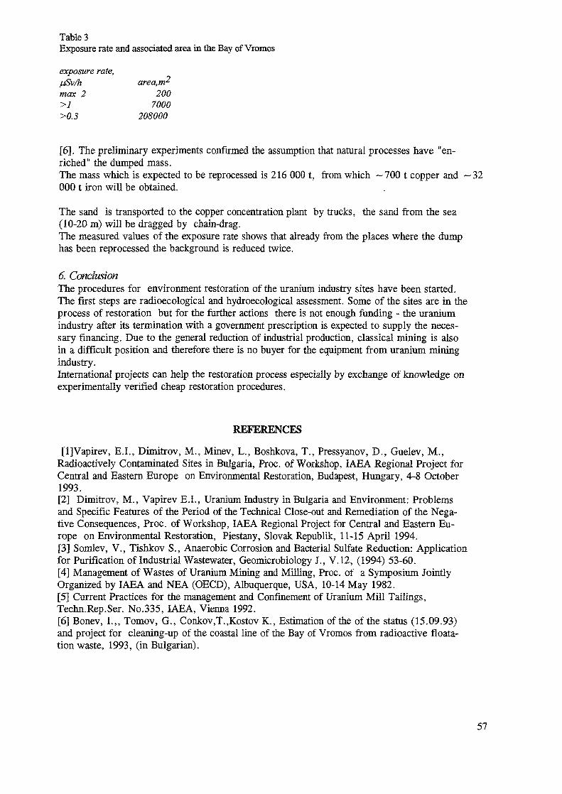
Table 3Exposure rate and associated area in the Bay of Vromos
exposure rate,/jSv/h area,m^max 2 200>1 7000>0.3 208000
[6], The preliminary experiments confirmed the assumption that natural processes have "en-riched" the dumped mass.The mass which is expected to be reprocessed is 216 000 t, from which —700 t copper and — 32000 t iron will be obtained.
The sand is transported to the copper concentration plant by trucks, the sand from the sea(10-20 m) will be dragged by chain-drag.The measured values of the exposure rate shows that already from the places where the dumphas been reprocessed the background is reduced twice.
6. ConclusionThe procedures for environment restoration of the uranium industry sites have been started.The first steps are radioecological and hydroecological assessment. Some of the sites are hi theprocess of restoration but for the further actions there is not enough funding - the uraniumindustry after its termination with a government prescription is expected to supply the neces-sary financing. Due to the general reduction of industrial production, classical mining is alsoin a difficult position and therefore there is no buyer for the equipment from uranium miningindustry.International projects can help the restoration process especially by exchange of knowledge onexperimentally verified cheap restoration procedures.
REFERENCES
[l]Vapirev, E.I., Dimitrov, M., Minev, L., Boshkova, T., Pressyanov, D., Guelev, M.,Radioactively Contaminated Sites in Bulgaria, Proc. of Workshop, IAEA Regional Project forCentral and Eastern Europe on Environmental Restoration, Budapest, Hungary, 4-8 October1993.[2] Dimitrov, M., Vapirev E.I., Uranium Industry in Bulgaria and Environment: Problemsand Specific Features of the Period of the Technical Close-out and Remediation of the Nega-tive Consequences, Proc. of Workshop, IAEA Regional Project for Central and Eastern Eu-rope on Environmental Restoration, Piestany, Slovak Republik, 11-15 April 1994.[3] Somlev, V., Tishkov S., Anaerobic Corrosion and Bacterial Sulfate Reduction: Applicationfor Purification of Industrial Wastewater, Geomicrobiology J., V.12, (1994) 53-60.[4] Management of Wastes of Uranium Mining and Milling, Proc. of a Symposium JointlyOrganized by IAEA and NBA (OECD), Albuquerque, USA, 10-14 May 1982.[5] Current Practices for the management and Confinement of Uranium Mill Tailings,Techn.Rep.Ser. No.335, IAEA, Vienna 1992.[6] Bonev, I.,, Tomov, G., Conkov,T.,Kostov K., Estimation of the of the status (15.09.93)and project for cleaning-up of the coastal line of the Bay of Vromos from radioactive floata-tion waste, 1993, (in Bulgarian).
57

TECHNOLOGIES FOR AND IMPLEMENTATION OFENVIRONMENTAL RESTORATION IN CANADA
R.W. POLLOCKLow-Level Radioactive Waste Management Office,Gloucester
D.G. FEASBYCanada Centre for Mineral and Energy Technology,Ottawa
Ontario, Canada
Abstract
This paper discusses the technologies for, and implementation of, environmental restorationat three types of sites present in Canada:
at historic low-level radioactive waste (LLRW) sites, resulting from the early years of theradium and uranium industry in Canada, which are the responsibility of the Low-LevelRadioactive Waste Management Office (LLRWMO).
- the Chalk River Laboratories (CRL) site of Atomic Energy of Canada Limited (AECL);
- decommissioning and waste management at uranium mining and milling sites.
The latter section deals primarily with sites for which the uranium production companiesare responsible for decommissioning. It has been included to describe Canadian experience inthis area since, from a technical perspective, there are many factors in common withrestoration programs at inactive or abandoned sites.
1. INTRODUCTION
This is the third of three papers presenting Canadian experience in environmentalrestoration at radioactively contaminated sites. The first two papers dealt with identificationand radiological characterization of contaminated sites in Canada [1] and planning forenvironmental restoration [2].
The sites which are the subjects of these papers have been primarily, but not exclusively,associated with mining, processing, transport and disposal of radioactive ores and theirby-products. In particular, events associated with the radium industry in Canada resulted incontaminated sites, which, although dating back to the 1930s, continue to be addressed today.
59
An historical overview of these activities is included in the first of this sequence of papers [1],and is not repeated here.
This paper is divided into three sections:
environmental restoration at historic low-level radioactive waste (LLRW) sites;
environmental restoration at the Chalk River Laboratories (CRL) site of Atomic Energy ofCanada Limited (AECL);
decommissioning and waste management at uranium mining and milling sites.
The latter section deals primarily with sites for which the uranium production companiesare responsible for decommissioning. It has been included to describe Canadian experience inthis area since, from a technical perspective, there are many factors in common withrestoration programs at inactive or abandoned sites.
2. ENVIRONMENTAL RESTORATION AT HISTORIC LOW-LEVELRADIOACTIVE WASTE SITES
2.1 Background
The Low-Level Radioactive Waste Management Office (LLRWMO) was established by thefederal government in 1982 to resolve historic waste problems (those for which the originalproducer can no longer reasonably be held responsible) that are a federal responsibility, toensure that a user-pay service is established for the disposal of low-level radioactive waste(LLRW) produced on an on-going basis, and to address public information needs concerningLLRW [3]. In Canada, low-level radioactive wastes are defined as all radioactive wastes otherthan nuclear fuel wastes and uranium mill tailings. These latter types of wastes are not withinthe mandate of the LLRWMO.
Historic low-level radioactive wastes date back to 1933 in Canada, when a radium refinerybegan operation in Port Hope, Ontario. The problem of residual wastes and contaminatedbuildings and soils in Port Hope, resulting from the practices in the early years of radium anduranium production, was discovered in the mid-1970s, and a large scale cleanup programcarried out. This work was concentrated on developed properties. As a result, substantialquantities of contaminated materials remained in a number of large undeveloped areas. Anumber of additional historic waste sites have subsequently been discovered at other locationsin Canada, where buildings and/or soils were contaminated with uranium ores or concentratesspilled during transport, or with processing residues, or as a result of the use of radiumcontaining materials. This section of the paper describes the technical approach being used atthese sites by the Low-Level Radioactive Waste Management Office. Conceptual designstudies and cost estimates for facilities designed specifically for disposal of large volumes ofbulk LLRW and contaminated soils are also discussed. These include both work donepreviously by the LLRWMO, and current work being by done by independent Siting TaskForces established to locate new sites for the long-term management of specific historic wasteinventories.
60
A major distinguishing factor between different sites is how the wastes resulting fromcleanups and related activities are managed. This section of the paper is organized on thisbasis, with the sites described in the first paper [1], and several others, described as examples.
2.2 Historic Waste Volumes Relative To Total LLRW Volumes In Canada
Table 1 (from next page) portrays the current and estimated future inventory of LLRW inCanada over the next 35 years or so [4].
It can be seen that low-level radioactive wastes to be managed in Canada fall into twobroad categories. The first is the large inventory of soils contaminated with natural long-livedradionuclides and, in most instances, heavy metal constituents including arsenic. These areprimarily located in the Port Hope area.
In addition to historic waste sites in Port Hope a number of other sites have beendiscovered. These include sites in Scarborough, Ontario and Surrey, British Columbia which,although the volumes of contaminated soils are much lower (less than 10,000 m3 at each area)have had a lengthy history of difficult social and political issues [5].
The most recent discoveries have been in northern Alberta and the NorthwestTerritories, along the transportation route from the old Port Radium mine. Watertransportation by barge along a 1,400 mile route of lakes and rivers was used to move suppliesin, and uranium ores and concentrates out to the railroad at Waterways, (now Fort McMurray)Alberta. A number of transfer points were needed, due to portages at rapids, and the need touse different sizes of equipment for different parts of the route.
A comprehensive survey program to identify residual contamination at these transferlocations has been completed. Cleanup work started in 1992, with the priorities being anycurrently inhabited sites and a series of old industrial properties in Fort McMurray whereextensive redevelopment is planned. Although the total volume of soil involved at the FortMcMurray sites is significant (in excess of 100,000 m3), new procedures for soilcharacterization and soil segregation have resulted in both volume reduction and earlyresolution of the problem.
The second category of wastes are those produced mainly by the nuclear industry, whichcontain primarily man-made radionuclides having a large range of half-lives. These areidentified as "ongoing" wastes and are currently stored by the major producers.
It can be noted that, in terms of the estimated volume to the year 2025, about 75% isexisting inventory.
2.3 Small Scale Sites
These are defined as historic waste sites where the waste volumes are small.
This is the typical situation at buildings where there is residual contamination from thepast use of radium paint. These cleanups have many similarities with decommissioning anddecontamination projects at nuclear fuel cycle and radioisotope facilities. Waste volumes areminimized by surface decontamination techniques and by careful segregation of contaminated
61
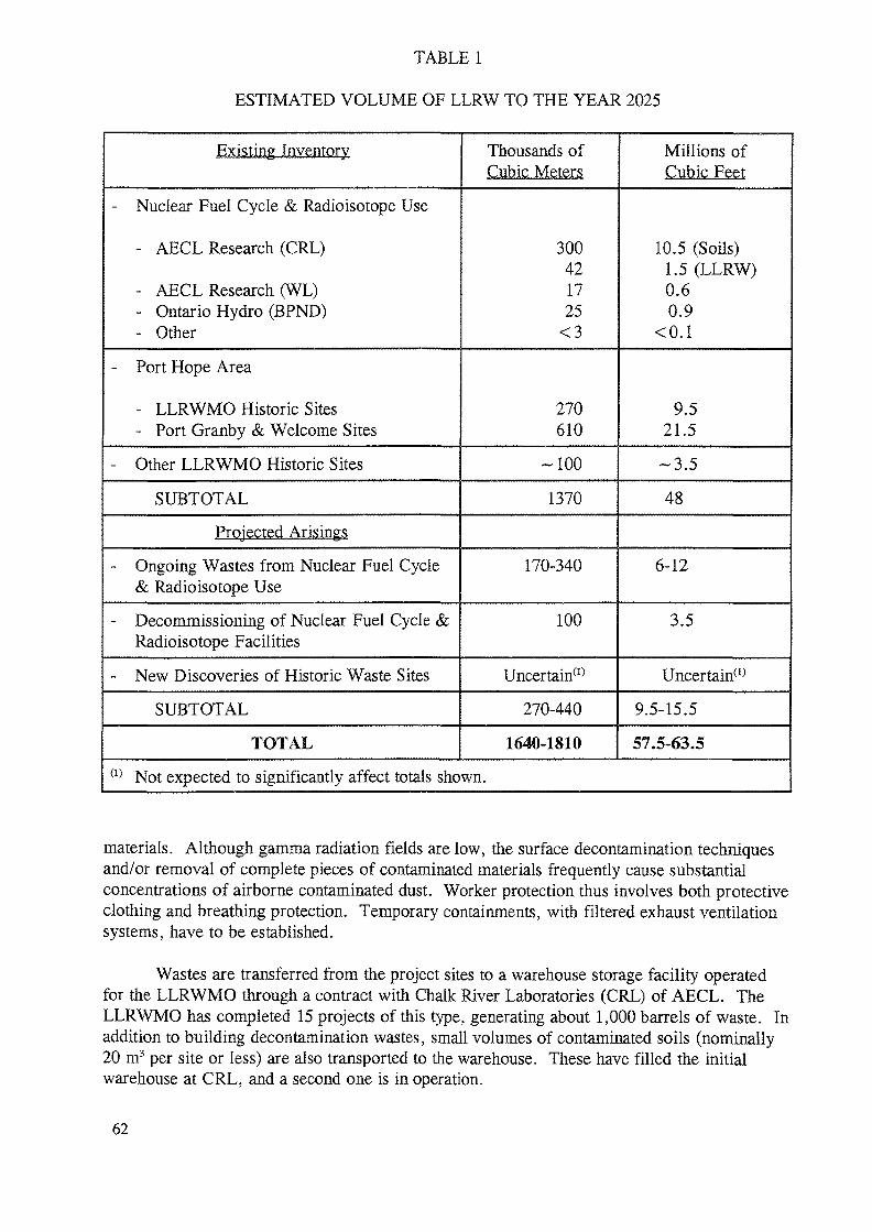
TABLE 1
ESTIMATED VOLUME OF LLRW TO THE YEAR 2025
Existing Inventory
- Nuclear Fuel Cycle & Radioisotope Use
- AECL Research (CRL)
- AECL Research (WL)- Ontario Hydro (BPND)- Other
- Port Hope Area
- LLRWMO Historic Sites- Port Granby & Welcome Sites
- Other LLRWMO Historic Sites
SUBTOTAL
Projected Arisings
- Ongoing Wastes from Nuclear Fuel Cycle& Radioisotope Use
- Decommissioning of Nuclear Fuel Cycle &Radioisotope Facilities
- New Discoveries of Historic Waste Sites
SUBTOTAL
TOTAL
Thousands ofCubic Meters
300421725<3
270610
-100
1370
170-340
100
Uncertain(1)
270-440
1640-1810
Millions ofCubic Feej
10.5 (Soils)1.5 (LLRW)0.60.9
<0.1
9.521.5
-3.5
48
6-12
3.5
Uncertain(1)
9.5-15.5
57.5-63.5(1) Not expected to significantly affect totals shown.
materials. Although gamma radiation fields are low, the surface decontamination techniquesand/or removal of complete pieces of contaminated materials frequently cause substantialconcentrations of airborne contaminated dust. Worker protection thus involves both protectiveclothing and breathing protection. Temporary containments, with filtered exhaust ventilationsystems, have to be established.
Wastes are transferred from the project sites to a warehouse storage facility operatedfor the LLRWMO through a contract with Chalk River Laboratories (CRL) of AECL. TheLLRWMO has completed 15 projects of this type, generating about 1,000 barrels of waste. Inaddition to building decontamination wastes, small volumes of contaminated soils (nominally20 m3 per site or less) are also transported to the warehouse. These have filled the initialwarehouse at CRL, and a second one is in operation.
62
2.4 Cleanups With Local Area Temporary Storage
Cleanup with temporary storage at, or near, the contaminated site is an interimremedial strategy. It is a standard approach now used by the LLRWMO for sites whereremedial action should be undertaken, but where the volumes of contaminated soil are toolarge for transfer to the warehouse type of storage facility at CRL, [6] [7].
Although final disposal is still required for these contaminated materials, these interimremedial actions have eliminated health risks and remedied environmental problems [8]. Thereare also general benefits to the community, in terms of eliminating negative perceptions andremoving constraints on land use.
Work practices and protocols have evolved over many years. Some aspects nowincluded in all LLRWMO projects are presented below.
Waste Delineation and Characterization. Thorough initial site investigations, includingradiological surveys of the surface and subsurface conditions, are undertaken and factored intoengineering designs. In 1992 the LLRWMO, together with the Borehole Geophysics Sectionof the Geological Survey of Canada, experimented with the installation of boreholes and use ofspectral logging protocols at a municipal landfill with historic waste contamination [9]. Thisproject has produced an improved field protocol for subsurface investigations in radon gasinfluenced environments.
Over the past two years, the LLRWMO has been developing large area surface gammasurvey protocols. A battery powered detection system with twin sodium iodide scintillatingdetectors and an on-board lap-top computer mounted on a simple cart comprised the hardware.The software and field scanning protocol are undergoing statistical sensitivity analysis andsoftware quality assurance. This approach is integral to survey work at Scarborough, Ontarioand Fort McMurray, Alberta remedial sites, where the equipment has to be manually portable,but able to cover large areas in a practical time.
However, supplementary investigations during the progress of the excavation work, aswell as direct supervision at the work face, is now common practice in LLRWMO projects.Rigorous attention to define and limit the materials excavated reduces volumes for futuremanagement, while still ensuring site cleanup to criteria levels.
Cleanup Operations. Standard construction equipment is used, with contaminationcontrol and health physics procedures which have been developed and proven over fifteenyears. Clear delineation of the contaminated work zones, thorough briefing of workers, andauditing of compliance are featured. Where practical, site-dedicated equipment and vehiclesare preferred. A predetermined staged approach to excavations and material movement on theremedial site is used. Continuous environmental monitoring is performed during the work.
In Situ Storage Facilities. LLRWMO experience with in situ consolidation and interimstorage projects has shown a number of advantages [6]. Containment of the waste preventsfurther spread of contamination thereby limiting the environmental impact and reducingremedial costs. Barriers applied over the waste protect potential intruders from any hazardsand also lessen the probability that unsuspecting parties will relocate and then further spreadthe problem. Covering the waste affords physical shielding to reduce gamma fields and
63
provide a barrier against radon emanation. In fact, the act of excavating and stockpiling wasteprovides self-shielding layers. An accurate understanding of the characteristics and volume ofthe waste requiring further long-term management is obtained when the materials aredelineated and excavated for interim consolidation. Progress is made toward final completionof remedial activities since most of the affected areas are cleaned and restored to the ultimatedesired level. Material is also prepared for easy future removal.
In situ consolidation and storage sites have much simpler designs than permanentdisposal facilities since, typically, a containment period of only a few years is expected. TheLLRWMO has used a number of interim storage approaches as part of its remedial workprogram at sites in Ontario, British Columbia, and the Northwest Territories. These include:engineered mounds, concrete block walled bunkers, and drummed storage within a fencedarea. Such storage sites hold as little as 50 and as many as 30,000 m3 of contaminated soil,but typically apply to inventories of a few thousand cubic meters.
Monitoring. Monitoring programs have also been developed over a number of yearsand encompass four broad areas:
normal background studies
The major contaminants at historic waste sites are naturally occurring radionuclides andheavy metals. Determining normal background values, and more importantly, their variabilityis thus important to both assessing and remediating contaminated sites.
Previous LLRWMO work in Ontario [10] is now being extended, through acomplementary project to a major program by the Ontario Ministry of the Environment toestablish typical ranges for a wide range of inorganic elements and organic substances. Localarea studies are also now carried out for all major historic waste sites. The LLRWMO alsoparticipates in joint projects relevant to determining natural background radioactivity in Canada[11].
worker protection
Worker exposures during remedial projects at historic waste sites have been sufficientlylow, due to the relatively low average radioactivity concentrations, that there has been no needto use Atomic Radiation Worker classifications. Standard radiation protection techniques areused to implement the ALARA principle. Personnel monitoring, using standard practices, isnonetheless carried out to demonstrate that radiation doses are well below dose limits formembers of the public [12].
environmental monitoring
Comprehensive environmental monitoring programs are carried out before, during, andafter major remedial projects [8]. Components are described in Table 2.
compliance (with cleanup criteria) sampling
Standard protocols, acceptable to regulatory agencies and property owners, have beendeveloped. They feature both field measurements of radiation, and collection and analyses ofsoil samples.
64
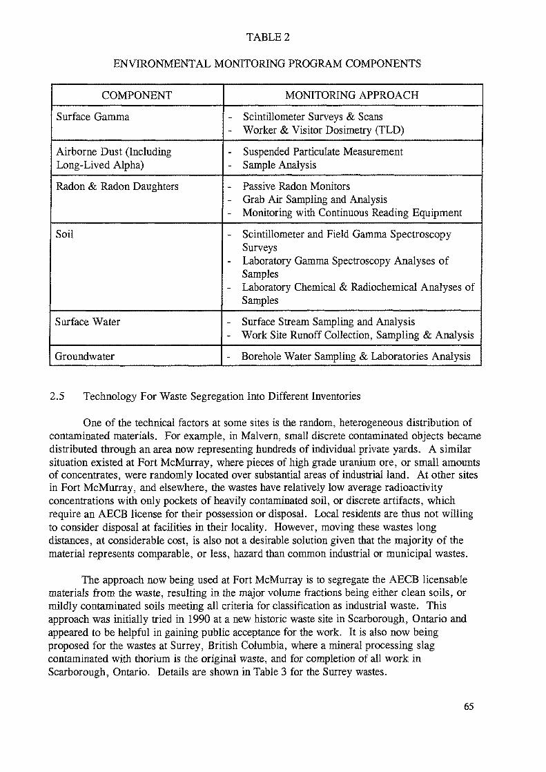
TABLE 2
ENVIRONMENTAL MONITORING PROGRAM COMPONENTS
COMPONENT
Surface Gamma
Airborne Dust (IncludingLong-Lived Alpha)
Radon & Radon Daughters
Soil
Surface Water
Groundwater
MONITORING APPROACH
- Scintillometer Surveys & Scans- Worker & Visitor Dosimetry (TLD)
- Suspended Particulate Measurement- Sample Analysis
- Passive Radon Monitors- Grab Air Sampling and Analysis- Monitoring with Continuous Reading Equipment
- Scintillometer and Field Gamma SpectroscopySurveys
- Laboratory Gamma Spectroscopy Analyses ofSamples
- Laboratory Chemical & Radiochemical Analyses ofSamples
- Surface Stream Sampling and Analysis- Work Site Runoff Collection, Sampling & Analysis
- Borehole Water Sampling & Laboratories Analysis
2.5 Technology For Waste Segregation Into Different Inventories
One of the technical factors at some sites is the random, heterogeneous distribution ofcontaminated materials. For example, in Malvern, small discrete contaminated objects becamedistributed through an area now representing hundreds of individual private yards. A similarsituation existed at Fort McMurray, where pieces of high grade uranium ore, or small amountsof concentrates, were randomly located over substantial areas of industrial land. At other sitesin Fort McMurray, and elsewhere, the wastes have relatively low average radioactivityconcentrations with only pockets of heavily contaminated soil, or discrete artifacts, whichrequire an AECB license for their possession or disposal. Local residents are thus not willingto consider disposal at facilities in their locality. However, moving these wastes longdistances, at considerable cost, is also not a desirable solution given that the majority of thematerial represents comparable, or less, hazard than common industrial or municipal wastes.
The approach now being used at Fort McMurray is to segregate the AECB licensablematerials from the waste, resulting in the major volume fractions being either clean soils, ormildly contaminated soils meeting all criteria for classification as industrial waste. Thisapproach was initially tried in 1990 at a new historic waste site in Scarborough, Ontario andappeared to be helpful in gaining public acceptance for the work. It is also now beingproposed for the wastes at Surrey, British Columbia, where a mineral processing slagcontaminated with thorium is the original waste, and for completion of all work inScarborough, Ontario. Details are shown in Table 3 for the Surrey wastes.
65
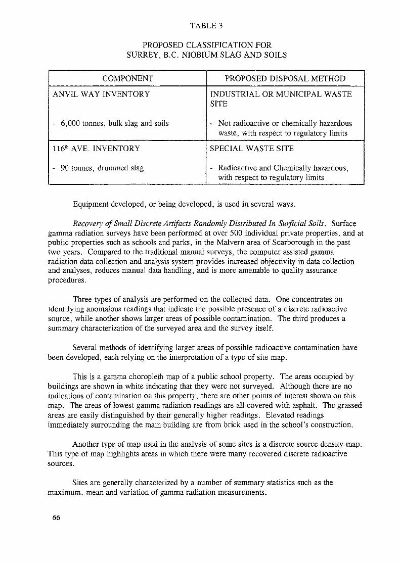
TABLE 3
PROPOSED CLASSIFICATION FORSURREY, B.C. NIOBIUM SLAG AND SOILS
COMPONENT PROPOSED DISPOSAL METHOD
ANVIL WAY INVENTORY
- 6,000 tonnes, bulk slag and soils
INDUSTRIAL OR MUNICIPAL WASTESITE
- Not radioactive or chemically hazardouswaste, with respect to regulatory limits
ll^AVE. INVENTORY
- 90 tonnes, drummed slag
SPECIAL WASTE SITE
- Radioactive and Chemically hazardous,with respect to regulatory limits
Equipment developed, or being developed, is used in several ways.
Recovery of Small Discrete Artifacts Randomly Distributed In Surficial Soils. Surfacegamma radiation surveys have been performed at over 500 individual private properties, and atpublic properties such as schools and parks, in the Malvern area of Scarborough in the pasttwo years. Compared to the traditional manual surveys, the computer assisted gammaradiation data collection and analysis system provides increased objectivity in data collectionand analyses, reduces manual data handling, and is more amenable to quality assuranceprocedures.
Three types of analysis are performed on the collected data. One concentrates onidentifying anomalous readings that indicate the possible presence of a discrete radioactivesource, while another shows larger areas of possible contamination. The third produces asummary characterization of the surveyed area and the survey itself.
Several methods of identifying larger areas of possible radioactive contamination havebeen developed, each relying on the interpretation of a type of site map.
This is a gamma choropleth map of a public school property. The areas occupied bybuildings are shown in white indicating that they were not surveyed. Although there are noindications of contamination on this property, there are other points of interest shown on thismap. The areas of lowest gamma radiation readings are all covered with asphalt. The grassedareas are easily distinguished by their generally higher readings. Elevated readingsimmediately surrounding the main building are from brick used in the school's construction.
Another type of map used in the analysis of some sites is a discrete source density map.This type of map highlights areas hi which there were many recovered discrete radioactivesources.
Sites are generally characterized by a number of summary statistics such as themaximum, mean and variation of gamma radiation measurements.
66
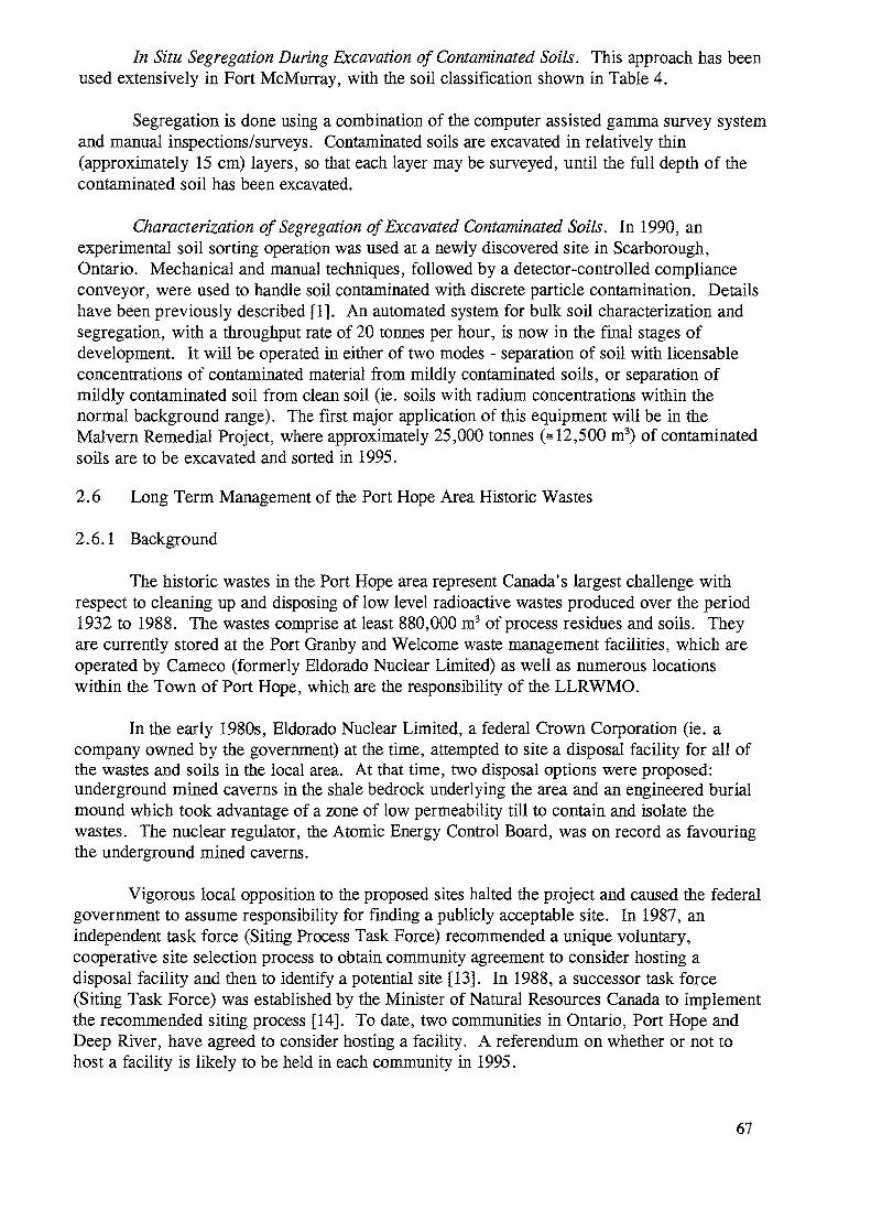
In Situ Segregation During Excavation of Contaminated Soils. This approach has beenused extensively in Fort McMurray, with the soil classification shown in Table 4.
Segregation is done using a combination of the computer assisted gamma survey systemand manual inspections/surveys. Contaminated soils are excavated in relatively thin(approximately 15 cm) layers, so that each layer may be surveyed, until the full depth of thecontaminated soil has been excavated.
Characterization of Segregation of Excavated Contaminated Soils. In 1990, anexperimental soil sorting operation was used at a newly discovered site in Scarborough,Ontario. Mechanical and manual techniques, followed by a detector-controlled complianceconveyor, were used to handle soil contaminated with discrete particle contamination. Detailshave been previously described [1]. An automated system for bulk soil characterization andsegregation, with a throughput rate of 20 tonnes per hour, is now in the final stages ofdevelopment. It will be operated in either of two modes - separation of soil with licensableconcentrations of contaminated material from mildly contaminated soils, or separation ofmildly contaminated soil from clean soil (ie. soils with radium concentrations within thenormal background range). The first major application of this equipment will be in theMalvern Remedial Project, where approximately 25,000 tonnes (* 12,500 m3) of contaminatedsoils are to be excavated and sorted in 1995.
2.6 Long Term Management of the Port Hope Area Historic Wastes
2.6.1 Background
The historic wastes in the Port Hope area represent Canada's largest challenge withrespect to cleaning up and disposing of low level radioactive wastes produced over the period1932 to 1988. The wastes comprise at least 880,000 m3 of process residues and soils. Theyare currently stored at the Port Granby and Welcome waste management facilities, which areoperated by Cameco (formerly Eldorado Nuclear Limited) as well as numerous locationswithin the Town of Port Hope, which are the responsibility of the LLRWMO.
In the early 1980s, Eldorado Nuclear Limited, a federal Crown Corporation (ie. acompany owned by the government) at the time, attempted to site a disposal facility for all ofthe wastes and soils in the local area. At that time, two disposal options were proposed:underground mined caverns in the shale bedrock underlying the area and an engineered burialmound which took advantage of a zone of low permeability till to contain and isolate thewastes. The nuclear regulator, the Atomic Energy Control Board, was on record as favouringthe underground mined caverns.
Vigorous local opposition to the proposed sites halted the project and caused the federalgovernment to assume responsibility for finding a publicly acceptable site. In 1987, anindependent task force (Siting Process Task Force) recommended a unique voluntary,cooperative site selection process to obtain community agreement to consider hosting adisposal facility and then to identify a potential site [13]. In 1988, a successor task force(Siting Task Force) was established by the Minister of Natural Resources Canada to implementthe recommended siting process [14]. To date, two communities in Ontario, Port Hope andDeep River, have agreed to consider hosting a facility. A referendum on whether or not tohost a facility is likely to be held in each community in 1995.
67
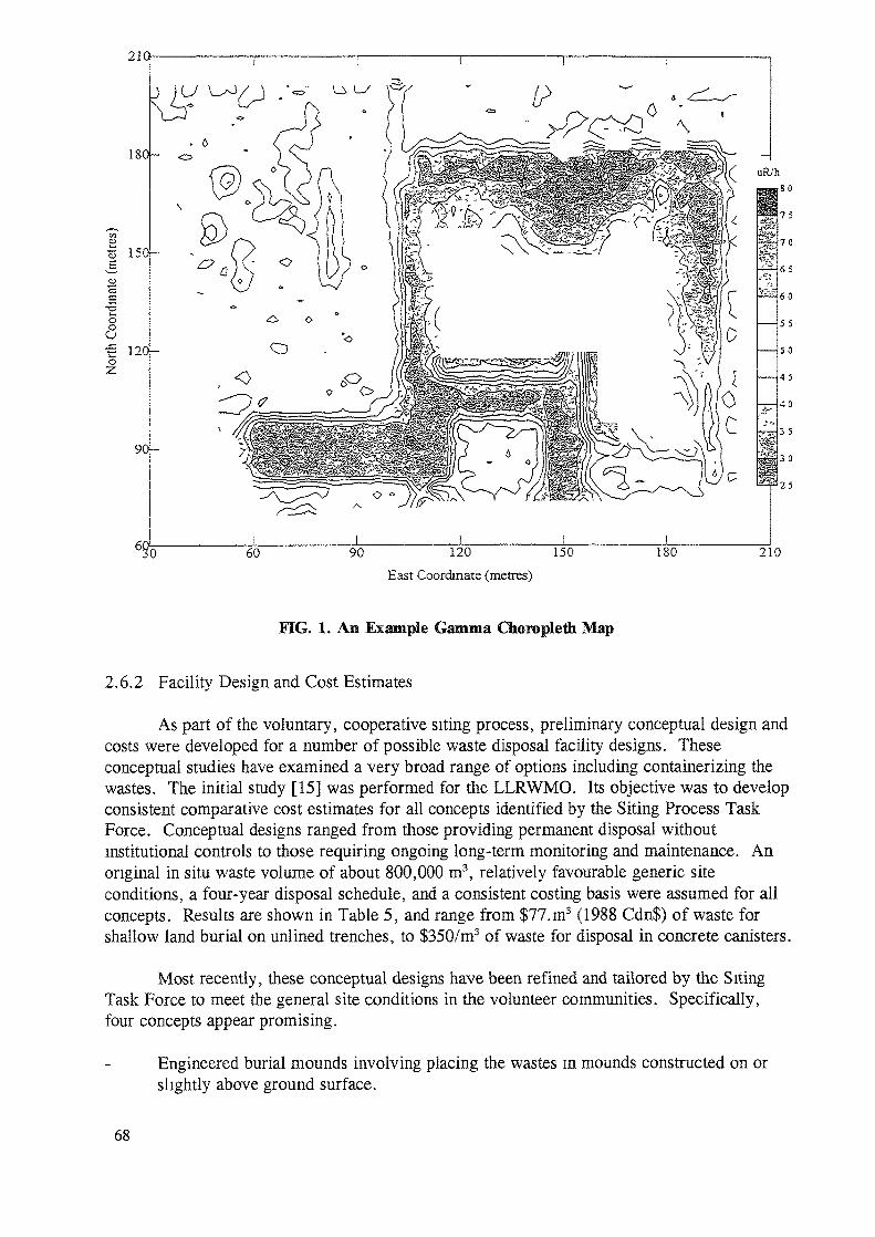
210
180-
•§ 150-
o(3
120h
60 90 120East Coordinate (metres)
150 180 210
FIG. 1. An Example Gamma Choropleth Map
2.6.2 Facility Design and Cost Estimates
As part of the voluntary, cooperative siting process, preliminary conceptual design andcosts were developed for a number of possible waste disposal facility designs. Theseconceptual studies have examined a very broad range of options including containerizing thewastes. The initial study [15] was performed for the LLRWMO. Its objective was to developconsistent comparative cost estimates for all concepts identified by the Siting Process TaskForce. Conceptual designs ranged from those providing permanent disposal withoutinstitutional controls to those requiring ongoing long-term monitoring and maintenance. Anoriginal in situ waste volume of about 800,000 m3, relatively favourable generic siteconditions, a four-year disposal schedule, and a consistent costing basis were assumed for allconcepts. Results are shown in Table 5, and range from $77.m3 (1988 Cdn$) of waste forshallow land burial on unlined trenches, to $350/m3 of waste for disposal in concrete canisters.
Most recently, these conceptual designs have been refined and tailored by the SitingTask Force to meet the general site conditions in the volunteer communities. Specifically,four concepts appear promising.
Engineered burial mounds involving placing the wastes in mounds constructed on orslightly above ground surface.
68
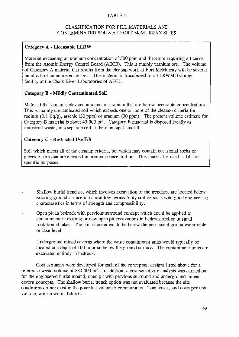
TABLE 4
CLASSIFICATION FOR FILL MATERIALS ANDCONTAMINATED SOILS AT FORT McMURRAY SITES
Category A - Licensable LLRW
Material exceeding an uranium concentration of 500 ppm and therefore requiring a licencefrom the Atomic Energy Control Board (AECB). This is mainly uranium ore. The volumeof Category A material that results from the cleanup work at Fort McMurray will be severalhundreds of cubic meters or less. This material is transferred to a LLRWMO storagefacility at the Chalk River Laboratories of AECL.
Category B - Mildly Contaminated Soil
Material that contains elevated amounts of uranium that are below licensable concentrations.This is mainly contaminated soil which exceeds one or more of the cleanup criteria forradium (0.1 Bq/g), arsenic (30 ppm) or uranium (30 ppm). The present volume estimate forCategory B material is about 40,000 m3 . Category B material is disposed locally asindustrial waste, in a separate cell at the municipal landfill.
Category C - Restricted Use Fill
Soil which meets all of the cleanup criteria, but which may contain occasional rocks orpieces of ore that are elevated in uranium concentration. This material is used as fill forspecific purposes.
Shallow burial trenches, which involves excavation of the trenches, are located belowexisting ground surface in natural low permeability soil deposits with good engineeringcharacteristics in terms of strength and compressibility.
Open pit in bedrock with pervious surround concept which could be applied tocontainment in existing or new open pit excavations in bedrock and/or in smallrock-bound lakes. The containment would be below the permanent groundwater tableor lake level.
Underground mined caverns where the waste containment units would typically belocated at a depth of 100 m or so below the ground surface. The containment units areexcavated entirely in bedrock.
Cost estimates were developed for each of the conceptual designs listed above for areference waste volume of 880,000 m3. In addition, a cost sensitivity analysis was carried outfor the engineered burial mound, open pit with pervious surround and underground minedcavern concepts. The shallow burial trench option was not evaluated because the siteconditions do not exist in the potential volunteer communities. Total costs, and costs per unitvolume, are shown in Table 6.
69
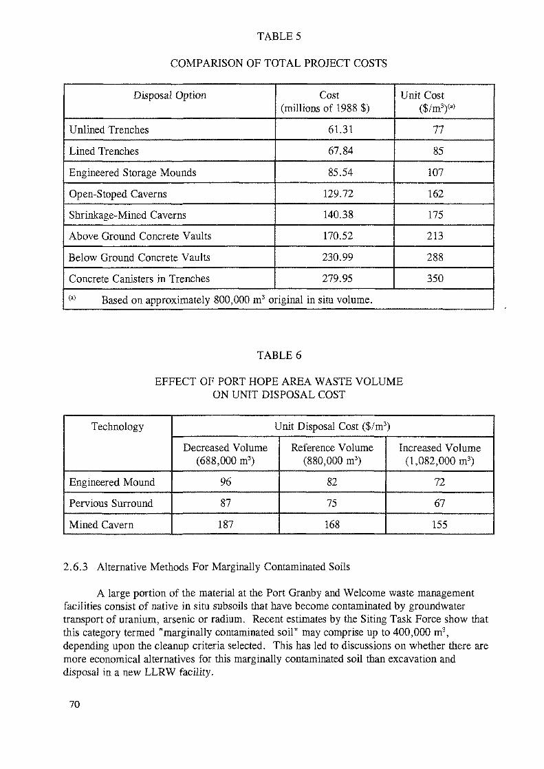
TABLE 5
COMPARISON OF TOTAL PROJECT COSTS
Disposal Option
Unlined Trenches
Lined Trenches
Engineered Storage Mounds
Open-Stoped Caverns
Shrinkage-Mined Caverns
Above Ground Concrete Vaults
Below Ground Concrete Vaults
Concrete Canisters in Trenches
Cost(millions of 1988 $)
61.31
67.84
85.54
129.72
140.38
170.52
230.99
279.95
Unit Cost($/m3)(a>
77
85
107
162
175
213
288
350(a) Based on approximately 800,000 m3 original in situ volume.
TABLE 6
EFFECT OF PORT HOPE AREA WASTE VOLUMEON UNIT DISPOSAL COST
Technology
Engineered Mound
Pervious Surround
Mined Cavern
Unit Disposal Cost ($/m3)
Decreased Volume(688,000 m3)
96
87
187
Reference Volume(880,000 m3)
82
75
168
Increased Volume(1,082,000 m3)
72
67
155
2.6.3 Alternative Methods For Marginally Contaminated Soils
A large portion of the material at the Port Granby and Welcome waste managementfacilities consist of native in situ subsoils that have become contaminated by groundwatertransport of uranium, arsenic or radium. Recent estimates by the Siting Task Force show thatthis category termed "marginally contaminated soil" may comprise up to 400,000 m3,depending upon the cleanup criteria selected. This has led to discussions on whether there aremore economical alternatives for this marginally contaminated soil than excavation anddisposal in a new LLRW facility.
70
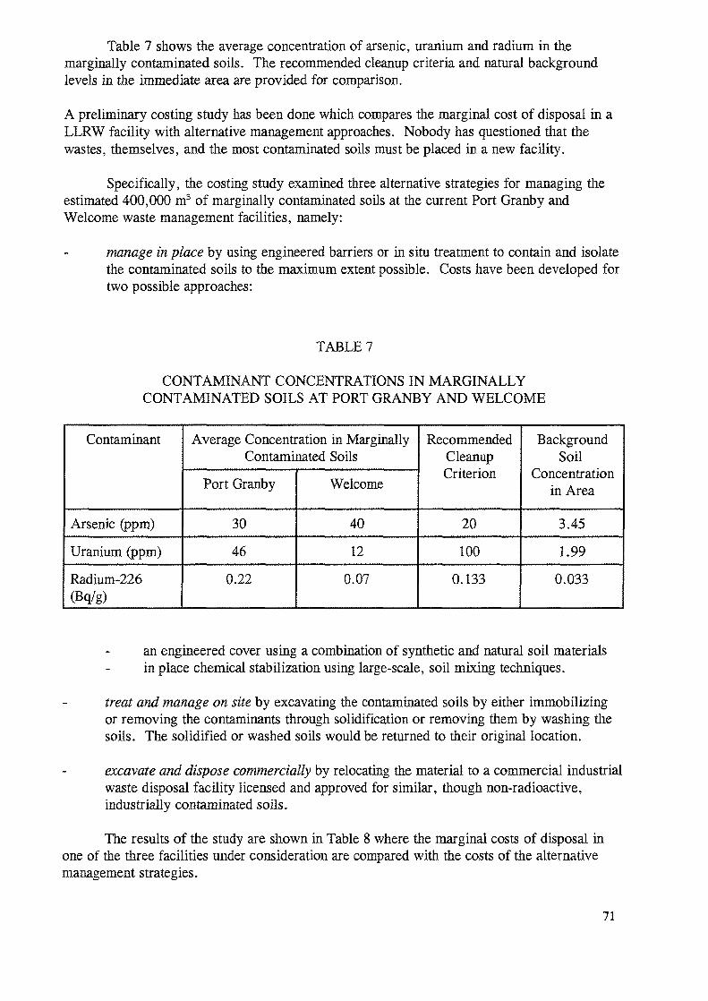
Table 7 shows the average concentration of arsenic, uranium and radium in themarginally contaminated soils. The recommended cleanup criteria and natural backgroundlevels in the immediate area are provided for comparison.
A preliminary costing study has been done which compares the marginal cost of disposal in aLLRW facility with alternative management approaches. Nobody has questioned that thewastes, themselves, and the most contaminated soils must be placed in a new facility.
Specifically, the costing study examined three alternative strategies for managing theestimated 400,000 m3 of marginally contaminated soils at the current Port Granby andWelcome waste management facilities, namely:
manage in place by using engineered barriers or in situ treatment to contain and isolatethe contaminated soils to the maximum extent possible. Costs have been developed fortwo possible approaches:
TABLE 7
CONTAMINANT CONCENTRATIONS IN MARGINALLYCONTAMINATED SOILS AT PORT GRANBY AND WELCOME
Contaminant
Arsenic (ppm)
Uranium (ppm)
Radium-226(Bq/g)
Average Concentration in MarginallyContaminated Soils
Port Granby
30
46
0.22
Welcome
40
12
0.07
RecommendedCleanupCriterion
20
100
0.133
BackgroundSoil
Concentrationin Area
3.45
1.99
0.033
an engineered cover using a combination of synthetic and natural soil materialsin place chemical stabilization using large-scale, soil mixing techniques.
treat and manage on site by excavating the contaminated soils by either immobilizingor removing the contaminants through solidification or removing them by washing thesoils. The solidified or washed soils would be returned to their original location.
excavate and dispose commercially by relocating the material to a commercial industrialwaste disposal facility licensed and approved for similar, though non-radioactive,industrially contaminated soils.
The results of the study are shown in Table 8 where the marginal costs of disposal inone of the three facilities under consideration are compared with the costs of the alternativemanagement strategies.
71
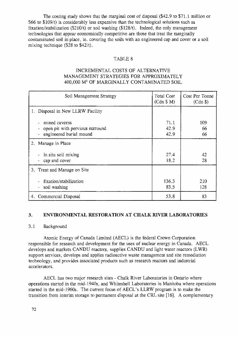
The costing study shows that the marginal cost of disposal ($42.9 to $71.1 million or$66 to $109/t) is considerably less expensive than the technological solutions such asfixation/stabilization ($210/t) or soil washing ($128/t). Indeed, the only managementtechnologies that appear economically competitive are those that treat the marginallycontaminated soil in place, ie. covering the soils with an engineered cap and cover or a soilmixing technique ($28 to $42/t).
TABLE 8
INCREMENTAL COSTS OF ALTERNATIVEMANAGEMENT STRATEGIES FOR APPROXIMATELY400,000 M3 OF MARGINALLY CONTAMINATED SOIL
Soil Management Strategy
1.
2.
3.
4.
Disposal in New LLRW Facility
- mined caverns- open pit with pervious surround- engineered burial mound
Manage in Place
- in situ soil mixing- cap and cover
Treat and Manage on Site
- fixation/stabilization- soil washing
Commercial Disposal
Total Cost(Cdn $ M)
71.142.942.9
27.418.2
136.383.5
53.8
Cost Per Tonne(Cdn $)
1096666
4228
210128
83
3. ENVIRONMENTAL RESTORATION AT CHALK RIVER LABORATORIES
3.1 Background
Atomic Energy of Canada Limited (AECL) is the federal Crown Corporationresponsible for research and development for the uses of nuclear energy in Canada. AECLdevelops and markets CANDU reactors, supplies CANDU and light water reactors (LWR)support services, develops and applies radioactive waste management and site remediationtechnology, and provides associated products such as research reactors and industrialaccelerators.
AECL has two major research sites - Chalk River Laboratories in Ontario whereoperations started in the mid-1940s, and Whiteshell Laboratories in Manitoba where operationsstarted in the mid-1960s. The current focus of AECL's LLRW program is to make thetransition from interim storage to permanent disposal at the CRL site [16]. A complementary
72
program is directed as assessing the need for remedial action at old CRL storage sites datingback to the 1940s and 1950s, and implementing the required remedial activities.
Waste management practices evolved over the years of operation of nuclear facilities atCRL. Initially there were no established practices and various approaches were taken withboth liquid and solid wastes. In some cases these practices, which were acceptable at the time,have led to radionuclide discharges to soil and the formation of groundwater contaminantplumes. Some specific trials were also conducted to determine the rate and extent ofsubsurface and ground water contamination that might result from inadvertent spills and togain specific knowledge from wastes placed purposely in the ground. There is no danger tothe general public as the specific waste sites are well within the boundaries of the laboratory,nor is there any risk to employees since the sites are well delineated with signed fences.
A strong and active hydrogeological program is in place at CRL to observe and tomodel radionuclide releases and to develop a thorough understanding of contaminant transportin saturated and unsaturated media. Recently, a remediation program was initiated to setpriorities on the cleanup and restoration of the contaminated sites on the CRL property, tomeet the environmental standards of stewardship outlined by the Federal Government. Part ofthe remediation program is to develop a suite of technologies that can be applied to theremoval of contaminants from soils and ground water in an efficient and cost-effective manner.
The radioisotope and fission product wastes, and associated contaminated soils, at theseold sites are of relatively short half-life compared to the natural radionuclides in the Port Hopearea, and other, historic wastes. Consequently, thee will be some differences in theapproaches to remedial action.
3.2 Ground water Remediation by Selective Contaminant Removal
Remediation technology for the removal of low concentrations of radionuclides, heavymetals and organics from ground water began several years ago by applying novel technologydeveloped for radionuclide removal from waste waters. The process involved adding watersoluble polymers to create macromolecules by attaching dissolved ions to the polymers. Themacromolecules were then removed from solution by using cross-flow ultrafiltration. Theprocess provided high removal efficiencies, it was highly selective in the removal of hazardoussubstances, and generated a minimal volume of secondary waste. Unfortunately, thetechnology is generally applicable to low ionic strength waters and the presence of largeconcentrations of iron caused the membranes to foul rapidly.
Building on the experience gained in laboratory and field investigations, the technologyto selectively remove contaminants was improved by switching to a more porous membraneand by altering the chemical treatment. By inducing precipitation and adding fine sorptionmaterials, similar removal efficiencies were achieved without the membranes being fouled bythe presence of iron while attaining low volumes of secondary waste requiring immobilizationand eventual disposal. The effluent quality achievable with the process can be made to complywith drinking water standards.
The technology has been successfully demonstrated on a contaminated site at CRL andis now in routine operation. Over the past two years, more than 2 million litres of water havebeen treated to reduce Sr-90 concentrations from about 2,500 Bq/L to < 1 Bq/L, with typicaleffluent values at 3 Bq/L, well below the Canadian drinking water standard set at 10 Bq/L.
73
The process in place involves the sequential addition of chemicals and adsorption/ionexchange materials to remove contaminants. The combination of chemical conditioning, cross-flow microfiltration and dewatering by filter pressing is effective for treating various groundwaters containing mixed wastes having diverse physical and chemical properties. The filtratewater is discharged once it meets the specified water quality. To achieve high quality water,up to three steps of chemical treatment and microfiltration may be employed to removecontaminants. The secondary waste volume is typically 1/500 the volume of the feed.
The chemical conditioning and microfiltration process has significant technicaladvantages and economic benefits for site remediation. The combined action of precipitation,co-precipitation, adsorption and ion-exchange coupled with cross-flow microfiltrationeffectively removes dissolved contaminants into a concentrated suspension. The direct contactof contaminants with iron and other metal precipitates provides high contaminant removalefficiencies and fast kinetics. Low cost ion exchange/adsorbent materials are utilized in acontinuous operation. Less space is required than conventional systems and the use of modularconstruction permits flexibility and adaptability to different flow requirements as well asproviding portability and ease of movement to a contaminated site. One of the features of theprocess is that it is sufficiently generic to permit treatment of waste solutions containing avariety of radioactive and hazardous substances.
3.3 Recent Advances
Further progress in site remediation has taken place with acidic soil leachates, generallycreated by oxidation and dissolution of sulfide-bearing wastes which in turn dissolve heavymetal contaminants. The application of ultrasonics after the addition of pH adjustmentchemicals, oxidants and precipitants leads to the removal of contaminants more rapidly. Withsubsequent separation of solids by cross-flow microfiltration and filter pressing, the overalltime for processing is generally reduced by an order of magnitude. Ultrasonic mixing hi placeof mechanical agitation in large tanks increases the conversion of contaminants to precipitatesand affects the rate by which oxidation and ion exchange takes place. Without large tanksrequired for sufficient time to allow processes to take place, the use of ultrasonics permits thesystem to be more compact, more portable, more energy efficient and requires less capital forconstruction. The technology generates minimal fugitive emissions and also produces atreated effluent that meets applicable discharge limits. The technology has also been able totreat waste containing small quantities of dissolved or suspended organics.
Soil washing has been evaluated to speed up the removal of contaminants from groundwater, by applying chemicals in solution directly to the soil. By stripping the contaminantsfrom the soil, the leachate can then be treated to extract the contaminants. Application ofin situ soil stripping could reduce the time required for treating contaminated ground water byeliminating the source.
Studies are underway at CRL to develop injection and recovery methods that will allowsoil treatment without having to disturb the soil. A key factor is having a good understandingof the hydrogeological properties of the contaminated site to properly situate the injection andrecovery wells. One of the successful materials for injection and removal of radioactivity fromCRL soils is dilute ferric chloride. Other dilute solvents can also be employed and aredependent on the contaminant to be extracted. Soil leaching tests established that the passageof five to six pore volumes of leachant solution removed close to 100% of all leachable Sr-90.
74
This leachate was then passed through the chemical treatment/microfiltration system to extractthe leached Sr-90. Further tests are planned at other CRL contaminated sites to improve theremoval of contaminants including uranium, cobalt, cesium, lead and other radionuclides andheavy metals.
There appears to be potential for application of these technologies to LLRWMOprojects. An initial laboratory scale test for removal of arsenic and uranium fromgroundwater from historic sites in Port Hope has produced good results.
4. DECOMMISSIONING AND WASTE MANAGEMENT AT URANIUM MINEAND MILLING SITES
4.1 Background
There are currently over 225 million tonnes of uranium mine tailings and mine wasterock on the surface in Canada. These wastes have been the subject of extensive research undertwo programs:
National Uranium Tailings Program (NUTP) 1983 - 1988; andMine Environmental Neutral Drainage (MEND) 1989 - 1997.
The NUTP was a federal government funded program of contract research, costing$8.5 M, that focussed on developing predictive techniques for disposal technology. MEND isa cooperative industry-governments program that focusses on one very important issue foruranium mine wastes in Canada, acid mine drainage.
Also, the Canadian industry has been developing site-specific technology thatminimizes the short and long-term impact of uranium mine wastes. The most significantdevelopment has been the progress from development to implementation of the pervious (orporous) surround technique that permits the disposal of wastes below surface and below thewater table.
4.2 Research and Technology Development
4.2.1 The National Uranium Tailings Program (NUTP)
The NUTP focussed on developing predictive geochemical models that would predictlong-term water quality from various decommissioned tailings management areas. The majormodel developed was the UTAP (Uranium Tailings Application Program) model which hasbeen continuously revised by its users since first developed in 1986. A major subset of theUTAP model development was a predictive model named RATAP (Reactive Acid TailingsApplication Program) which predicts the progress and impact of acid-generating sulphides intailings.
The NUTP research had confirmed that a major environmental threat from uraniumtailings in Canada was acid generation from residual sulphides, particularly in the Elliot Lakedistrict. This acid-generation is particularly severe because the very strong acid leachingsolutions needed to attack the brannerite-uraninite minerals had destroyed all residual naturalalkalinity.
75
Among the decommissioning technologies investigated under the NUTP was the use ofsimple soil and enhanced vegetative covers for tailings. For stacked tailings sites, the simplecovers were shown to have minimal impact on the geochemical activity of the tailings,particularly acid generation.
4.2.2 The Mine Environment Neutral Drainage Program
Acidic drainage is not only a problem for the uranium industry but it is the largestsingle environmental problem facing the world's metal mining industry today. Technologiesto prevent, or substantially reduce, acidic drainage from occurring in waste rock piles andtailings sites and mine walls need to be improved and demonstrated. These new technologieswill substantially reduce the operating and closure costs at existing mine sites and in therehabilitation of abandoned mine sites.
A decade ago, the Canadian mining industry and government laboratories hadconducted research into rehabilitation of mine sites, with a special focus on uranium tailingssites by establishing sustainable vegetative growth on tailings and waste rock. It was believedthat this technology would alleviate acid drainage problems from these sites, thus allowingmining companies to abandon these sites without future liability. However, after severalyears, the quality of water drainage from vegetated waste sites had not improved, and propertyowners were faced with the prospect of continuing to operate and maintain lime and bariumchloride treatment plants indefinitely. It was clear that more knowledge and expertise neededto be developed and new remedial technology needed to be developed and demonstrated.
As a consequence, in 1988 the Canadian mining industry, 5 provincial governmentsand the government of Canada cooperated to form a tripartite consortium organized under theMine Environment Neutral Drainage (MEND) Program. Since then, the two levels ofgovernment and the Canadian mining industry have together committed $18 million on MENDprojects to find ways to reduce the liabilities caused by the natural acidification of mineralwastes.
MEND is focussing on the development of new technologies that will reduce theestimated $5 billion liability that would be incurred if the known, reliable, but costly remedialtechnologies were used. For example, it is currently estimated that multi-zone earth coverswould cost between $15 and $30/m2, and even if installed, could reduce acid production byonly 90 %. This reduction, although significant, would not permit the treatment plants to beshut down for a long time.
Indefinite collection and treatment of acidic waters may be an option at many sites, butthe significant annual cost plus the storage problem of accumulated sludges is also costly andproblematic. Also, Canadian regulators do not favour long-term treatment as adecommissioning option.
Some examples of the technology being developed in over 100 MEND projects that areapplicable to uranium mine wastes are:
Refined chemical prediction procedures have been developed to determine if waste rockor tailings will acidify.
76
Predictive geochemical models for tailings and waste rock are being modified and newones developed. Models that will predict the performance of dry soil covers on stackedtailings and rock piles are being field-evaluated.
Underwater disposal is being confirmed as the best prevention technology forunoxidized sulphide-containing wastes. Field and laboratory studies have confirmedthat reactive sulphide tailings and waste rock do not react underwater in the naturalenvironment. Natural or engineered water cover systems with an organic surface orsedimentation layer prevent the minor amounts of oxygen dissolved in water fromoxidizing sulphides. Underwater disposal in engineered impoundments to prevent acidproduction is now a common feature in proposals for new mines in Canada.
Water covers to control acid generation-in already oxidized tailings and rock is alsobeing investigated and implemented. Results to date on Elliot Lake uranium tailingsshow that oxidation is effectively stopped and techniques are being developed tominimize water contamination so that treatment plants can be shut down in a few years.Two methods have been used to engineer the water cover:
"move the wedge by dredge" - Denison Mines"rice paddy" concept - Rio Algom
The Denison Long Lake 280 hectare tailings area has been levelled by dredging thebeach tailings area into lower areas of the impoundment, and the whole area has beenflooded. In the few months that the tailings have been flooded, surface water qualityhas substantially improved.
The Quirke 190 hectare tailings area is being flooded by establishing a series of internaldykes. The first cell, Cell No. 14, has been extensively monitored, and the waterquality is approaching natural background quality.
Unfortunately, many of the uranium and base metal mine waste sites are not physicallysuitable for water covers. MEND has extensively investigated multi-zone earth coversfor tailings and waste rock. These covers are effective, but are very costly to install inmany areas of Canada. Innovative "dry" cover research is indicating that severalmaterials, including waste materials from other industries provide excellent potential atlower cost for generating moisture retaining, oxygen-consuming surface barriers.
Several other disposal technologies that will reduce acid generation are beinginvestigated:
permafrost covers about 40% of Canada, and cold conditions inhibit oxidation;
an elevated water table, if it can be maintained in the long-term, can be asignificant part of a tailings decommissioning scenario. Thickened tailingsdischarge is being investigated by an active uranium producer in Saskatchewan.
Depyritized and fine tailings are also showing excellent potential as covers.Depyritization has been extensively investigated by the Elliot Lake uraniumcompanies and has been rejected for economic and environmental reasons;
77
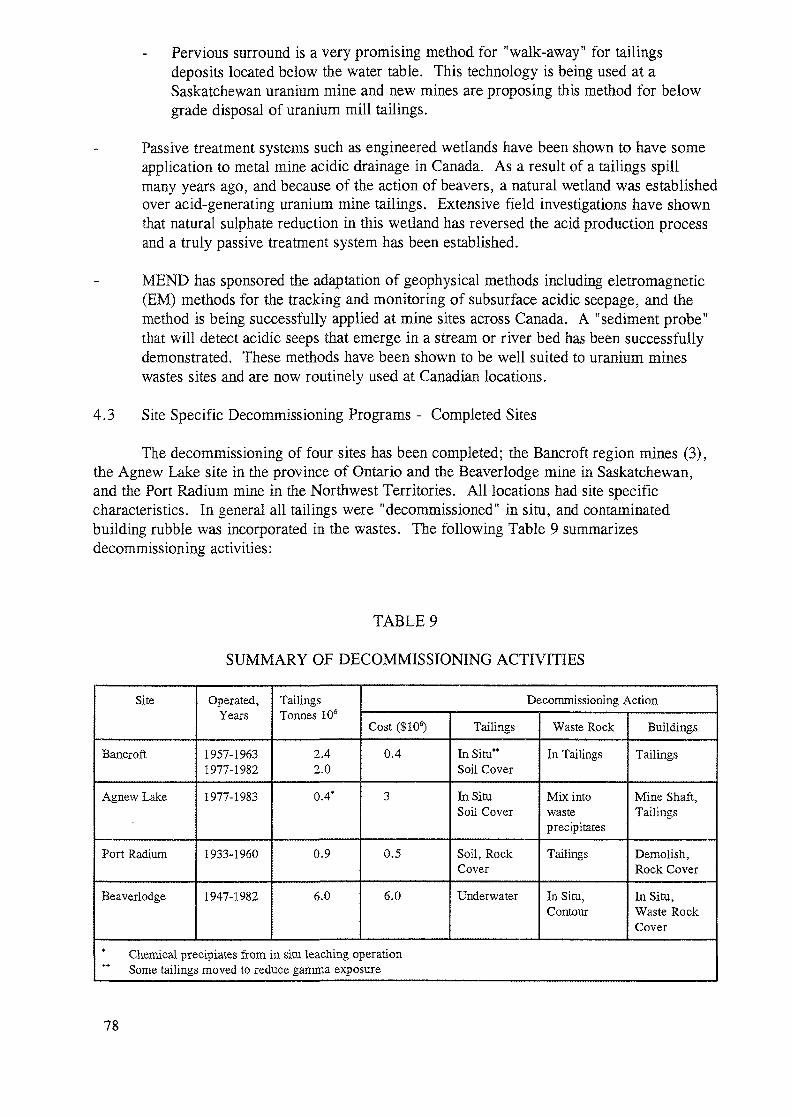
Pervious surround is a very promising method for "walk-away" for tailingsdeposits located below the water table. This technology is being used at aSaskatchewan uranium mine and new mines are proposing this method for belowgrade disposal of uranium mill tailings.
Passive treatment systems such as engineered wetlands have been shown to have someapplication to metal mine acidic drainage in Canada. As a result of a tailings spillmany years ago, and because of the action of beavers, a natural wetland was establishedover acid-generating uranium mine tailings. Extensive field investigations have shownthat natural sulphate reduction in this wetland has reversed the acid production processand a truly passive treatment system has been established.
MEND has sponsored the adaptation of geophysical methods including eletromagnetic(EM) methods for the tracking and monitoring of subsurface acidic seepage, and themethod is being successfully applied at mine sites across Canada. A "sediment probe"that will detect acidic seeps that emerge in a stream or river bed has been successfullydemonstrated. These methods have been shown to be well suited to uranium mineswastes sites and are now routinely used at Canadian locations.
4.3 Site Specific Decommissioning Programs - Completed Sites
The decommissioning of four sites has been completed; the Bancroft region mines (3),the Agnew Lake site in the province of Ontario and the Beaverlodge mine in Saskatchewan,and the Port Radium mine in the Northwest Territories. All locations had site specificcharacteristics. In general all tailings were "decommissioned" in situ, and contaminatedbuilding rubble was incorporated in the wastes. The following Table 9 summarizesdecommissioning activities:
TABLE 9
SUMMARY OF DECOMMISSIONING ACTIVITIES
Site
Bancroft
Agnew Lake
Port Radium
Beaverlodge
Operated,Years
1957-19631977-1982
1977-1983
1933-1960
1947-1982
TailingsTonnes 106
2.42.0
0.4*
0.9
6.0
Decommissioning Action
Cost ($106)
0.4
3
0.5
6.0
Tailings
In Situ"Soil Cover
In SituSoil Cover
Soil, RockCover
Underwater
Waste Rock
In Tailings
Mix intowasteprecipitates
Tailings
In Situ,Contour
Buildings
Tailings
Mine Shaft,Tailings
Demolish,Rock Cover
In Situ,Waste RockCover
Chemical precipiates from in situ leaching operation** Some tailings moved to reduce gamma exposure
78
All sites except Bancroft sites are remote from extensive habitation and this resultedin intrusion not being a major factor in the decommissioning programs.
4.4 Development of Plans for Decommissioning of Elliot Lake Mine Tailings
4.4.1 Background
In 1953, uranium deposits were discovered along the northern shore of Lake Huronin Ontario. Over the next four years (1955 to 1958) twelve mines were brought intoproduction and, by 1959, a town of more than 25,000 people had been located on theeastern shore of Elliot Lake in northern Ontario.
Tailings were smrried and discharged, usually to low-lying areas of small lakes.Dams were used at some locations to assist in the containment of discharged materials.Tailings effluents were neutralized to a pH of 6 to 7, the range of values found in the lakesand rivers of the areas. At the time, these waste management techniques satisfied thegovernment agencies responsible for the licensing and monitoring of such practices.
In addition to uranium (and daughters), the Elliot Lake ores contain pyrite (about6% FeS2).
Underground, bacterial oxidation of pyrite turns mine water acidic, subsequentlypermitting the dissolution of various heavy metals and radionuclides also present in the ore.One of the earliest environmental concerns identified in the Elliot Lake area stemmed fromthe initial practice of discharging untreated acidic mine water to nearby lakes and streams.The most notable example of this situation, was Quirke Lake which received untreated minewater from several mines in the late 1950s. Within a few years the pH of the lake, thelargest in the region's drainage basin, had decreased dramatically to pH 2-3.Approximately two years after the start of mining, the practice of pumping mine water backto the mills for treatment was started. Since that time, mine water has been recycled intothe milling circuits. This reduced both the amount of fresh water used in the mill and theamount of effluents that eventually discharged to the environment.
The hectic years of the 1950s were followed by a downturn in the 1960s. The early1970s saw an increased demand for uranium which resulted in expansion to Elliot Lakeuranium mining activities. More recently, the diminishing ore grades and consequenthigher cost of Elliot Lake uranium has lead to progressive shutdown of mines. Today onlyRio Algom's Stanleigh mine remains in operation. Two companies, Rio Algom andDenison Mines are in the process of decommissioning properties in Elliot Lake. The plansdescribed in the following sections have been proposed to the public review currently inprocess through the federal Environmental Assessment and Review Process (EARP). Theprojects were referred to this environmental review by the Atomic Energy ControlBoard (AECB), the nuclear regulatory agency in Canada.
4.4.2 Development of Decommissioning Plans
Numerous decommissioning studies have been carried out for the Elliot Lakeproperties. Decommissioning plans for mines typically involved removing stationary andmobile equipment, piping, electric and all hazardous materials. This is followed by staged
79
sealing of underground workings and the shutting off of ventilation systems. Undergroundraises and shafts are capped as they are no longer needed. Salvageable equipment isrecovered from and decontaminated prior to sale. Surface facilities are demolished andrubble placed in the tailings basins or in vertical mine openings as appropriate. The mineswere then allowed to flood.
Various tailings management facilities decommissioning options have been studied.These include:
Wet Cover Options. Wet cover involves the placement of water over the entireexposed tailings. The objectives are to:
prevent acid generation and the associated leaching of metals and radionuclides;provide a barrier to intrusion onto the tailings;essentially eliminate radon and dust emissions.
Dry Cover Options. Dry cover involves the placement of fill over the exposedtailings. The objectives are to:
raise the water table above the acid generating tailings to prevent the acidificationand associated leaching of metals and radionuclides;provide a physical barrier to intrusion onto the tailings; andreduce radon and dust emissions.
For the soil cover option, soil cover could be an inert material including sand,gravel, till, or crushed rock. The cover would be vegetated to minimize erosion andstabilize the surface.
Dry cover can also be achieved by the placement of pyrite-reduced tailings in lieu ofsoil.
For the pyrite-reduced cover, depyritized tailings would be placed to a depth ofabout three meters over the exposed tailings with the objective of elevating the water tableabove the surface of the reactive tailings and thereby halting acidification.
Another dry cover concept is the application of a radionuclide-reduced cover.Several options for the removal of radionuclides from tailings were considered. However,none of these processes are fully effective.
4.4.3 Lake Disposal
Lake disposal requires the relocation of tailings at depth in a natural lake. Theobjectives are the same as those for the wet cover scenario.
The concept includes dredging the tailings at existing tailings areas and thickeningthe tailings slurry, followed by pumping of the thickened tailings to Quirke Lake fordisposal. Quirke Lake covers an area of 20 km2, with a mean depth of 30 m.
80
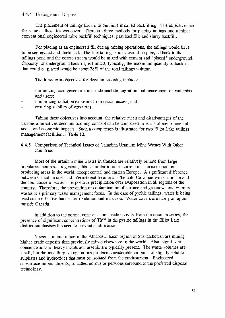
4.4.4 Underground Disposal
The placement of tailings back into the mine is called backfilling. The objectives arethe same as those for wet cover. There are three methods for placing tailings into a mine:conventional engineered mine backfill techniques; past backfill; and slurry backfill.
For placing as an engineered fill during mining operations, the tailings would haveto be segregated and thickened. The fine tailings slimes would be pumped back to thetailings pond and the coarse stream would be mixed with cement and "placed" underground.Capacity for underground backfill, is limited, typically, the maximum quantity of backfillthat could be placed would be about 28 % of the total tailings volume.
The long-term objectives for decommissioning include:
minimizing acid generation and radionuclide migration and hence input on watershedand users;minimizing radiation exposure from casual access, andensuring stability of structures.
Taking these objectives into account, the relative merit and disadvantages of thevarious alternatives decommissioning concept can be compared in terms of environmental,social and economic impacts. Such a comparison is illustrated for two Elliot Lake tailingsmanagement facilities in Table 10.
4.4.5 Comparison of Technical Issues of Canadian Uranium Mine Wastes With OtherCountries
Most of the uranium mine wastes in Canada are relatively remote from largepopulation centres. In general, this is similar to other current and former uraniumproducing areas in the world, except central and eastern Europe. A significant differencebetween Canadian sites and international locations is the cold Canadian winter climate andthe abundance of water - net positive precipitation over evaporation in all regions of thecountry. Therefore, the prevention of contamination of surface and groundwaters by minewastes is a primary waste management focus. In the case of pyritic tailings, water is beingused as an effective barrier for oxidation and intrusion. Water covers are rarely an optionoutside Canada.
In addition to the normal concerns about radioactivity from the uranium series, thepresence of significant concentrations of Th232 in the pyritic tailings in the Elliot Lakedistrict emphasises the need to prevent acidification.
Newer uranium mines in the Athabasca basin region of Saskatchewan are mininghigher grade deposits than previously mined elsewhere in the world. Also, significantconcentrations of heavy metals and arsenic are typically present. The waste volumes aresmall, but the metallurgical operations produce considerable amounts of slightly solublesulphates and hydroxides that must be isolated from the environment. Engineeredsubsurface impoundments, so called porous or pervious surround is the preferred disposaltechnology.
81
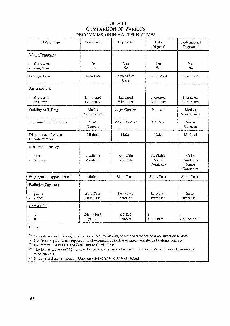
TABLE 10COMPARISON OF VARIOUS
DECOMMISSIONING ALTERNATIVESOption Type
Water Treatment
- short term- long term
Seepage Losses
Air Emissions
- short term- long term
Stability of Tailings
Intrusion Considerations
Disturbance of AreasOutside WMAs
Resource Recovery
- mine- tailings
Employment Opportunities
Radiation Exposure
- public- worker
Cost fSM)(1)
- A- B
Wet Cover
YesNo
Base Case
EliminatedEliminated
ModestMaintenance
MinorConcern
Minimal
AvailableAvailable
Minimal
Base CaseBase Case
$4(+S26)(2>
($15)(2)
Dry Cover
YesNo
Same as BaseCase
IncreasedEliminated
Major Concern
Major Concern
Major
AvailableAvailable
Short Term
DecreasedIncreased
$38458$20428
LakeDisposal
YesYes
Eliminated
IncreasedEliminated
No Issue
No Issue
Major
AvailableMajor
Constraint
Short Term
IncreasedIncreased
}} $238<3)
UndergroundDisposal(5)
YesNo
Decreased
IncreasedEliminated
ModestMaintenance
MinorConcern
Minimal
MajorConstraint
MinorConstraint
Short Term
SameIncreased
}} $674223(4)
m Costs do not include engineering, long-term monitoring or expenditures for dam construction to date.(2) Numbers in parenthesis represent total expenditures to date to implement flooded tailings concept.(3) For removal of both A and B tailings to Quirke Lake.(4) The low estimate ($67 M) applies to use of slurry backfill while the high estimate is for use of engineered
mine backfill.(5) Not a "stand alone" option. Only disposes of 25% to 35 % of tailings.
82
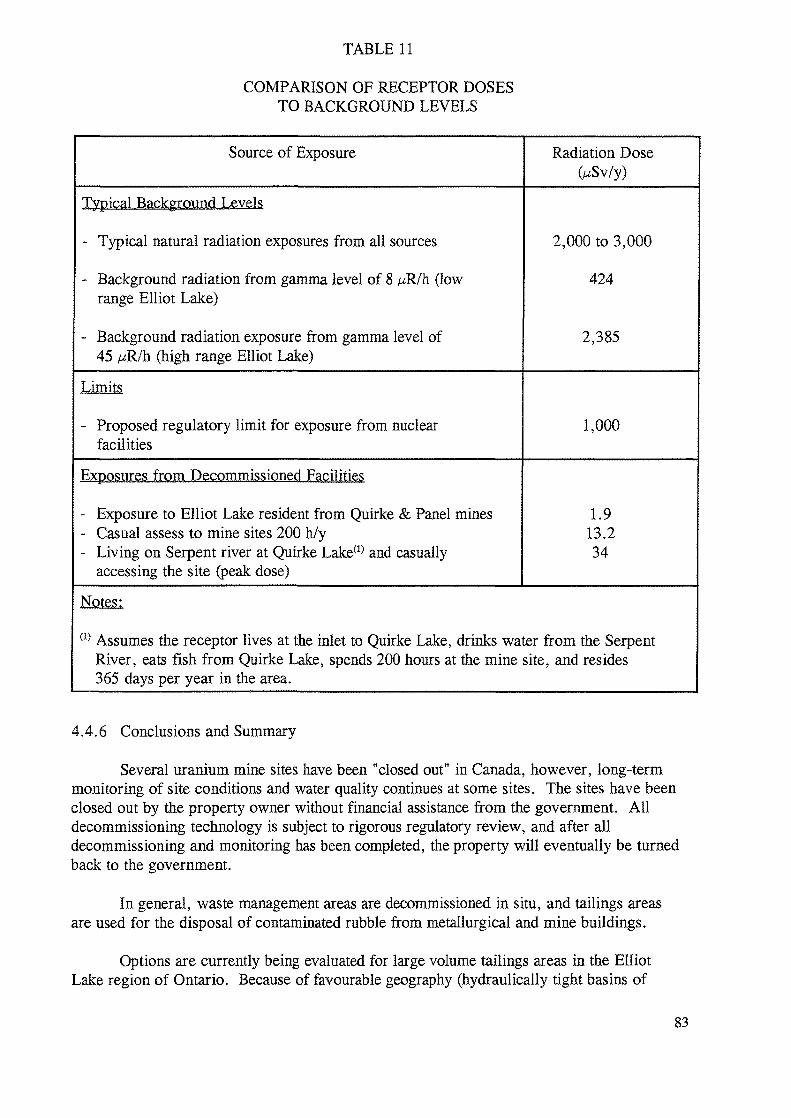
TABLE 11
COMPARISON OF RECEPTOR DOSESTO BACKGROUND LEVELS
Source of Exposure Radiation Dose
Typical Background Levels
- Typical natural radiation exposures from all sources
- Background radiation from gamma level of 8 p;R/h (lowrange Elliot Lake)
- Background radiation exposure from gamma level of45 fjR/h (high range Elliot Lake)
2,000 to 3,000
424
2,385
- Proposed regulatory limit for exposure from nuclearfacilities
1,000
Exposures from Decommissioned Facilities
- Exposure to Elliot Lake resident from Quirke & Panel mines- Casual assess to mine sites 200 h/y- Living on Serpent river at Quirke Lake(1> and casually
accessing the site (peak dose)
1.913.234
Notes:
(1) Assumes the receptor lives at the inlet to Quirke Lake, drinks water from the SerpentRiver, eats fish from Quirke Lake, spends 200 hours at the mine site, and resides365 days per year in the area.
4.4.6 Conclusions and Summary
Several uranium mine sites have been "closed out" in Canada, however, long-termmonitoring of site conditions and water quality continues at some sites. The sites have beenclosed out by the property owner without financial assistance from the government. Alldecommissioning technology is subject to rigorous regulatory review, and after alldecommissioning and monitoring has been completed, the property will eventually be turnedback to the government.
In general, waste management areas are decommissioned hi situ, and tailings areasare used for the disposal of contaminated rubble from metallurgical and mine buildings.
Options are currently being evaluated for large volume tailings areas in the ElliotLake region of Ontario. Because of favourable geography (hydraulically tight basins of
83
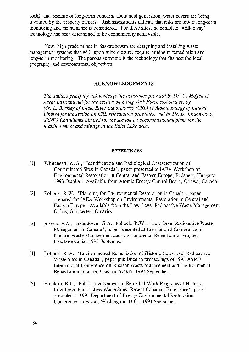
rock), and because of long-term concerns about acid generation, water covers are beingfavoured by the property owners. Risk assessments indicate that risks are low if long-termmonitoring and maintenance is considered. For these sites, no complete "walk away"technology has been determined to be economically achievable.
New, high grade mines in Saskatchewan are designing and installing wastemanagement systems that will, upon mine closure, require minimum remediation andlong-term monitoring. The porous surround is the technology that fits best the localgeography and environmental objectives.
ACKNOWLEDGEMENTS
The authors gratefully acknowledge the assistance provided by Dr. D. Moffett ofAcres International for the section on Siting Task Force cost studies, byMr. L. Buckley of Chalk River Laboratories (CRL) of Atomic Energy of CanadaLimited for the section on CRL remediation programs, and by Dr. D. Chambers ofSENES Consultants Limited for the section on decommissioning plans for theuranium mines and tailings in the Elliot Lake area.
REFERENCES
[1] Whitehead, W.G., "Identification and Radiological Characterization ofContaminated Sites in Canada", paper presented at IAEA Workshop onEnvironmental Restoration in Central and Eastern Europe, Budapest, Hungary,1993 October. Available from Atomic Energy Control Board, Ottawa, Canada.
[2] Pollock, R.W., "Planning for Environmental Restoration in Canada", paperprepared for IAEA Workshop on Environmental Restoration in Central andEastern Europe. Available from the Low-Level Radioactive Waste ManagementOffice, Gloucester, Ontario.
[3] Brown, P.A., Underdown, G.A., Pollock, R.W., "Low-Level Radioactive WasteManagement in Canada", paper presented at International Conference onNuclear Waste Management and Environmental Remediation, Prague,Czechoslovakia, 1993 September.
[4] Pollock, R.W., "Environmental Remediation of Historic Low-Level RadioactiveWaste Sites in Canada", paper published in proceedings of 1993 ASMEInternational Conference on Nuclear Waste Management and EnvironmentalRemediation, Prague, Czechoslovakia, 1993 September.
[5] Franklin, B.J., "Public Involvement in Remedial Work Programs at HistoricLow-Level Radioactive Waste Sites, Recent Canadian Experience", paperpresented at 1991 Department of Energy Environmental RestorationConference, inPasco, Washington, D.C., 1991 September.
84
[6] Zelmer, R.L., "In Situ Storage: An Approach to Interim Remedial Action - RecentCase Studies in Canada", paper presented at the 1991 Department of EnergyEnvironmental Restoration Conference, Pasco, Washington, USA,1991 September 8-11.
[7] Zelmer, R.L., "Fifteen Years of Experience in Remedial Action Programs forHistoric LLR Waste in Canada", paper presented at Waste Management '93,Tucson, USA, 1993 March.
[8] McCallum, B.A., Main, D.E., Zelmer, R.L., "Reductions in EnvironmentalImpacts at Interim Work Sites in Canada", paper presented at the RadiationProtection Symposium and Joint Conference of the Canadian Radiation ProtectionAssociation, Winnipeg, Canada, 1991 June 16-22. Available from LLRWMO,Gloucester, Ontario.
[9] Killeen, P.G., Pflug, K., Mwenifumbo, C.J., Zelmer, R.L., McCallum B.A.,"Application of Borehole Geophysics to Low-Level Radioactive WasteManagement Studies at Port Hope, Ontario", abstracts from Forum 1993Anniversary 150 Issue, 1993.
[10] McCallum, B.A., "A Gamma Spectroscopic Analysis of the Distribution of 226Ra inOntario Soils: A Preliminary Study", Proceedings of the Twenty-Sixth MidyearTopical Meeting of the Health Physics Society, Idaho, 1993 January.
[11] Bigu, J., McCallum, B.A., Grasty, R.L., "Environmental Levels of Thoron, Radonand Their Progeny in Manitoba, Canada", proceedings of the Twenty-SixthMidyear Topical Meeting of the Health Physics Society, Idaho, 1993 January.
[12] Case, G.G., Zelmer, R.L., "Assessment of Radiation Exposures to Workers Duringan Historic Waste Consolidation Project" paper presented at the RadiationProtection Symposium and Joint Conference of the Canadian RadiationProtection Association, Winnipeg, Canada, 1991 June.
[13] Siting Process Task Force on LLR Waste Management, "Opting For Cooperation",1987. Available from the STF Secretariat, Natural Resources Canada, Ottawa,Ontario.
[14] Siting Task Force Secretariat, "A Process in Action", report of the Siting TaskForce, Low-Level Radioactive Waste Management 1990. Available from theSTF Secretariat, Natural Resources Canada, Ottawa, Ontario.
[15] AECL-9911, "Conceptual Costing Study for the Long-Term Management of the PortHope Area Low-Level Radioactive Wastes, 1989 December. Prepared for theLow-Level Radioactive Waste Management Office by Colder Associates, AcresInternational Limited, SENES Consultants Limited and Whiteshell Laboratoriesof Atomic Energy of Canada Limited.
[16] Charlesworth, D.H., "Progress Toward Disposal of LLRW in Canada", paperpresented at 1989 Joint International Waste Management Conference, Kyoto,Japan, 1989 October. Available as Report AECL-9960, Chalk RiverLaboratories, AECL, Chalk River, Ontario.
85
RESTORATION OF RADIOACTFVELY CONTAMINATEDSITES IN THE REPUBLIC OF CROATIA
D. SUBASIC, A. SCHALLERA.P.O. Hazardous Waste Management Agency
D. BARISIC, S. LULIC, B. VEKICInstitute "Ruder Boskovic"Zagreb
J. KOVAC, N. LOKOBAUER, G. MAROVICInst. for Medical Res. and Occup. HealthZagreb
CROATIA
Abstract
'This report brings results of performed investigations and analyses, but alsoshows information of relevant past researches referring to three highlyprioritised sites: INA-VINIL Plant, PLOMIN Power Plant and INA-PETROKEMUAPlant. This information serves as a suitable start-point for furtherinvestigations, which are - according to the programme schedule - foreseento be completed by the end 1997. The report also gives somerecommendations for the personnel of INA-PETROKEMUA Plant, being in thisway useful for everyday practice in the only fertiliser factory in Croatia.
1. SITES SUSPECTED TO BE RADIOACTIVELY CONTAMINATED
As it is previously mentioned, there are four main groups of sites in Croatiawhich are suspected to be radioactively contaminated: (1) sites containingcoal slag/ash piles; (2) sites containing phosphates and waste gypsum (i.e.phospho-gypsum) from fertilizers industry; (3) geotherma! springs and oil/gasdrilling sites; (4) sites containing natural radioactive materials used in.humanactivities.
Consequently, following sites were initially examined as possible radioactivelycontaminated spots in our country:
A- Sites containing coal slag/ash piles1. Coal-fired power plant Plomin2. "INA-VINIL", the PVC synthesis and treatment plant, Kaste! Sucurac3. Power plant Zagreb (old slag piles)4. Coal-fired power plant Jertovec
It should be also mentioned that additional quantities of coal-slag and ashhave been used at numerous fire-rooms of individual buildings, institutions(hospitals, schools) etc. Furthermore, some attention should be also payed tothe old slag/ash piles remaining from use in railway transportation.
87
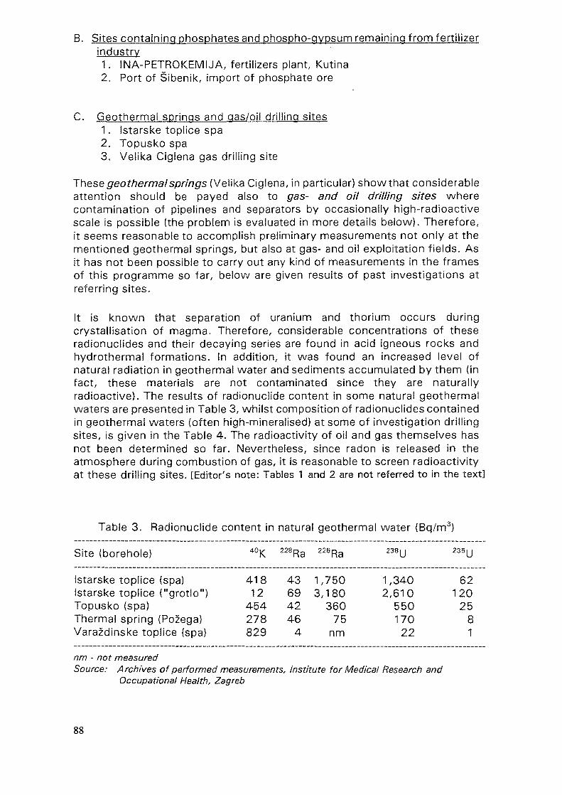
B. Sites containing phosphates and phospho-gypsum remaining from fertilizerindustry1. INA-PETROKEMIJA, fertilizers plant, Kutina2. Port of Sibenik, import of phosphate ore
C. Geothermai springs and gas/oil drilling sites1. Istarske toplice spa2. Topusko spa3. Velika Ciglena gas drilling site
These geothermalsprings (\ie\\kaC\Q\ena, in particular) show that considerableattention should be payed also to gas- and oil drilling sites wherecontamination of pipelines and separators by occasionally high-radioactivescale is possible (the problem is evaluated in more details below). Therefore,it seems reasonable to accomplish preliminary measurements not only at thementioned geothermal springs, but also at gas- and oil exploitation fields. Asit has not been possible to carry out any kind of measurements in the framesof this programme so far, below are given results of past investigations atreferring sites.
It is known that separation of uranium and thorium occurs duringcrystallisation of magma. Therefore, considerable concentrations of theseradionuclides and their decaying series are found in acid igneous rocks andhydrothermal formations. In addition, it was found an increased level ofnatural radiation in geothermal water and sediments accumulated by them (infact, these materials are not contaminated since they are naturallyradioactive). The results of radionuclide content in some natural geothermalwaters are presented in Table 3, whilst composition of radionuclides containedin geothermai waters (often high-mineraiised) at some of investigation drillingsites, is given in the Table 4. The radioactivity of oil and gas themselves hasnot been determined so far. Nevertheless, since radon is released in theatmosphere during combustion of gas, it is reasonable to screen radioactivityat these drilling sites. [Editor's note: Tables 1 and 2 are not referred to in the text]
Table 3. Radionuciide content in natural geothermal water (Bq/m3)
Site (borehole) 40K 228Ra 226Ra 238U 235U
Istarske toplice (spa)Istarske toplice ("grotlo")Topusko (spa)Thermal spring (Pozega)Varazdinske toplice (spa)
41812
454278829
43694246
4
1,7503,180
36075
nm
1,3402,610
55017022
62120
2581
nm - not measuredSource: Archives of performed measurements, Institute for Medical Research and
Occupational Health, Zagreb
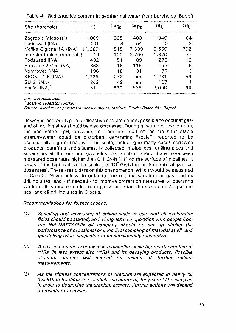
Table 4. Radionuclide content in geothermal water from boreholes (Bq/m3)
Site (borehole) 40K 228Ra 226Ra 238U 235U
Zagreb ("Mladost")Podsused (INA)Velika Ciglena 1A (INA) 1Istarske toplice (borehole)Podsused (INA)Borehole 7215 (INA)Kumrovec (INA)KBCNZ-1 B (INA)SU-3 (INA)Scale (INA)*
1,060131
1,26019
492368196
1,226342511
3059
515100
511618
27242
530
40054
7,0802,700
89115
31nmnm
878
1,34040
6,5501,670
273193
771,281
1072,090
642
302771393
591
96
nm -notmeasured;* scale in separator (Bq/kg)Source: Archives of performed measurements, Institute "Ruder BoSkovic", Zagreb
However, another type of radioactive contamination, possible to occur at gas-and oil drilling sites should be also discussed. During gas- and oil exploration,the parameters (pH, pressure, temperature, etc.) of the "in situ" stablestratum-water could be disturbed, generating "scale", reported to beoccasionally high-radioactive. The scale, including in many cases corrosionproducts, paraffins and silicates, is collected in pipelines, drilling pipes andseparators at the oil- and gas-fields. As an illustration, there have beenmeasured dose rates higher than 0.1 Gy/h [11] on the surface of pipelines incases of the high-radioactive scale (i.e. 107 Gy/h higher than natural gamma-dose rates). There are no data on this phenomenon, which would be measuredin Croatia. Nevertheless, in order to find out the situation at gas- and oildrilling sites, and - if needed - to improve protection measures of operatingworkers, it is recommended to organise and start the scale sampling at thegas- and oil drilling sites in Croatia.
Recommendations for further actions:
(1) Sampling and measuring of drilling scale at gas- and oil explorationfields should be started, and a long-term co-operation with people fromthe INA-NAFTAPLIN oil company should be set up aiming theperformance of occasional or periodical sampling of material at oil- andgas drilling sites, suspected to be considerably radioactive.
(2) As the most serious problem in radioactive scale figures the content of226Ra (in less extent also 228Ra) and its decaying products. Possibleclean-up actions will depend on results of further radiummeasurements.
(3) As the highest concentrations of uranium are expected in heavy oildistillation fractions (i. e. asphalt and bitumen), they should be sampledin order to determine the uranium activity. Further actions will dependon results of analyses.
89
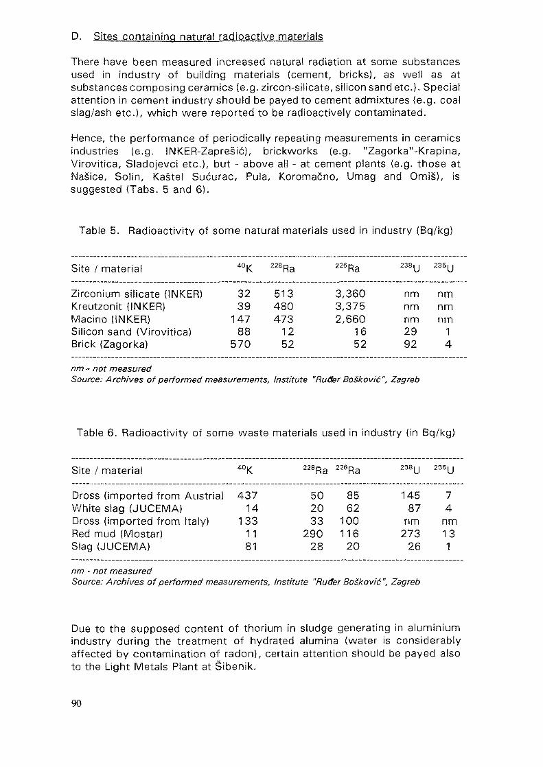
D. Sites containing natural radioactive materials
There have been measured increased natural radiation at some substancesused in industry of building materials (cement, bricks), as well as atsubstances composing ceramics (e.g. zircon-silicate, silicon sand etc.}. Specialattention in cement industry should be payed to cement admixtures (e.g. coalslag/ash etc.), which were reported to be radioactively contaminated.
Hence, the performance of periodically repeating measurements in ceramicsindustries (e.g. INKER-Zapresic), brickworks (e.g. "Zagorka"-Krapina,Virovitica, Sladojevci etc.), but - above ali - at cement plants (e.g. those atNasice, Soiin, Kastel Sucurac, Pula, Koromacno, Umag and Omis), issuggested (Tabs. 5 and 6).
Table 5. Radioactivity of some natural materials used in industry (Bq/kg)
Site / material 40K 228Ra 226 Ra 238u 235U
Zirconium silicate (INKER)Kreutzonit (INKER)Macino (INKER)Silicon sand {Virovitica)Brick (Zagorka)
3239
14788
570
513480473
1252
3,3603,3752,660
1652
nmnmnm2992
nmnmnm
14
nm "-not measuredSource: Archives of performed measurements, Institute "Ruder BoSkovi'6", Zagreb
Table 6. Radioactivity of some waste materials used in industry (in Bq/kg)
Site / material 40K 228Ra 226Ra 238U
235U
Dross (imported from Austria)White slag (JUCEMA)Dross (imported from Italy)Red mud (Mostar)Slag (JUCEMA)
43714
1331181
502033
29028
8562
100116
20
14587
nm273
26
74
nm131
nm -notmeasuredSource: Archives of performed measurements. Institute "Ruder Boskovic", Zagreb
Due to the supposed content of thorium in sludge generating in aluminiumindustry during the treatment of hydrated alumina (water is considerablyaffected by contamination of radon), certain attention should be payed alsoto the Light Metals Plant at Sibenik.
90
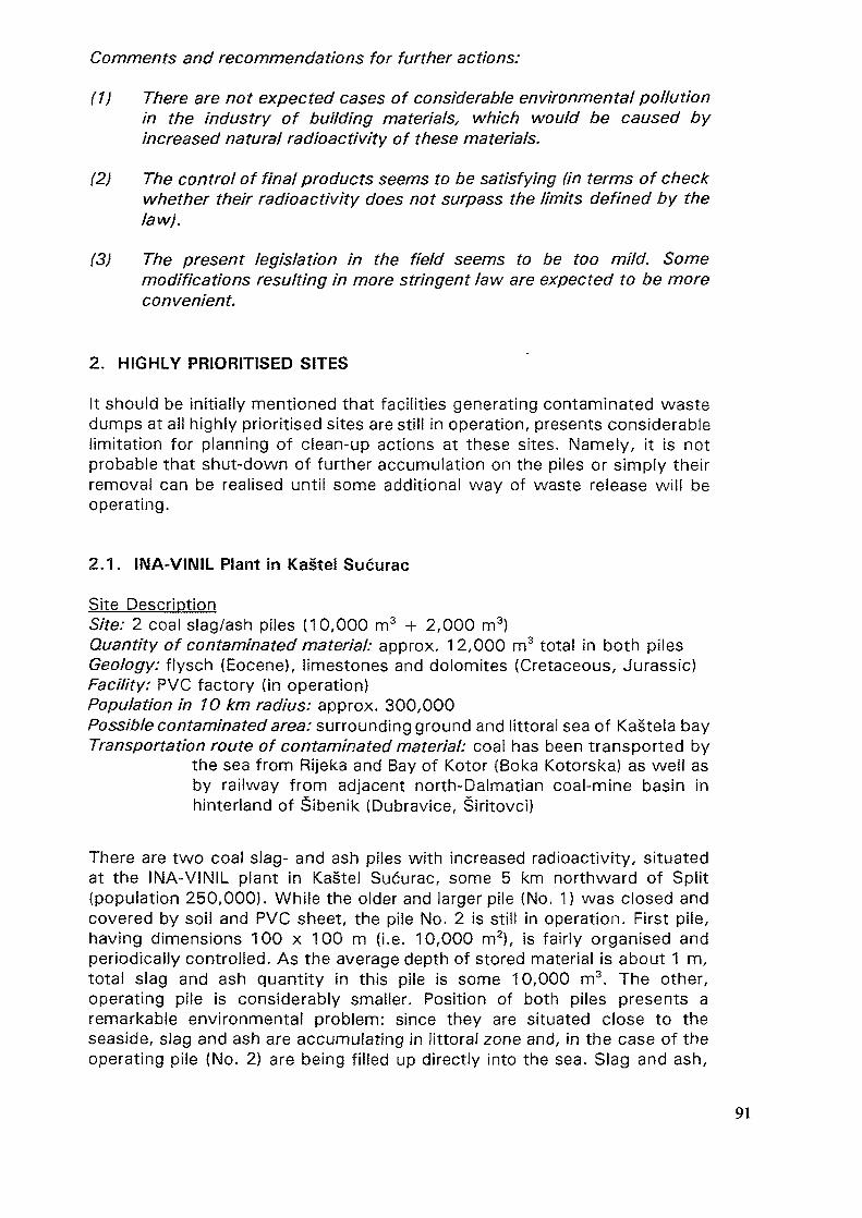
Comments and recommendations for further actions:
(1) There are not expected cases of considerable environmental pollutionin the industry of building materials, which would be caused byincreased natural radioactivity of these materials.
(2) The control of final products seems to be satisfying (in terms of checkwhether their radioactivity does not surpass the limits defined by thelaw).
(3) The present legislation in the field seems to be too mild. Somemodifications resulting in more stringent law are expected to be moreconvenient.
2. HIGHLY PRIORITISED SITES
It should be initially mentioned that facilities generating contaminated wastedumps at ail highly prioritised sites are still in operation, presents considerablelimitation for planning of clean-up actions at these sites. Namely, it is notprobable that shut-down of further accumulation on the piles or simply theirremoval can be realised until some additional way of waste release will beoperating.
2.1. IIMA-VINIL Plant in Kastel Sucurac
Site DescriptionSite: 2 coal slag/ash piles (10,000 m3 + 2,000 m3}Quantity of contaminated material: approx. 12,000 m3 total in both pilesGeology: flysch (Eocene), limestones and dolomites (Cretaceous, Jurassic)Facility: PVC factory (in operation)Population in 10 km radius: approx. 300,000Possible contaminated area: surrounding ground and littoral sea of Kasteia bayTransportation route of contaminated material: coal has been transported by
the sea from Rijeka and Bay of Kotor (Boka Kotorska) as well asby railway from adjacent north-Dalmatian coal-mine basin inhinterland of Sibenik (Dubravice, Siritovci)
There are two coal slag- and ash piles with increased radioactivity, situatedat the INA-VINIL plant in Kastel Sucurac, some 5 km northward of Split(population 250,000). While the older and larger pile (No. 1) was closed andcovered by soil and PVC sheet, the pile No. 2 is still in operation. First pile,having dimensions 100 x 100 m (i.e. 10,000 m2), is fairly organised andperiodically controlled. As the average depth of stored material is about 1 m,total slag and ash quantity in this pile is some 10,000 m3. The other,operating pile is considerably smaller. Position of both piles presents aremarkable environmental problem: since they are situated close to theseaside, slag and ash are accumulating in littoral zone and, in the case of theoperating pile (No. 2) are being filled up directly into the sea. Slag and ash,
91
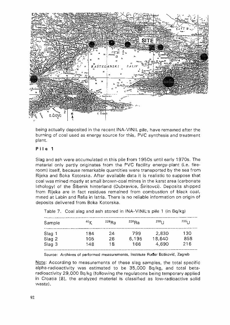
being actually deposited in the recent INA-VINIL pile, have remained after theburning of coal used as energy source for this, PVC synthesis and treatmentplant.
Pi I e 1
Slag and ash were accumulated in this pile from 1950s until early 1 970s. Thematerial only partly originates from the PVC facility energy-plant (i.e. fire-room) itself, because remarkable quantities were transported by the sea fromRijeka and Boka Kotorska. After available data it is realistic to suppose thatcoal was mined mostly at small brown-coal mines in the karst area (carbonatelithology) of the Sibenik hinterland (Dubravice, Siritovci). Deposits shippedfrom Rijeka are in fact residues remained from combustion of black coal,mined at Labin and Rasa in Sstria. There is no reliable information on origin ofdeposits delivered from Boka Kotorska.
Table 7. Coal slag and ash stored in INA-VlNILs pile 1 (in Bq/kg)
Sample
Slag 1Slag 2Slag 3
«K
184105148
228Ra
242618
226Ra
7996,195
166
238U
2,83018,640
4,690
235U
130858216
Source: Archives of performed measurements. Institute Ruder BoSkovic, Zagreb
Note: According to measurements of these slag samples, the total specificalpha-radioactivity was estimated to be 35,000 Bq/kg, and total beta-radioactivity 29,000 Bq/kg (following the regulations being temporary appliedin Croatia [8], the analyzed material is classified as low-radioactive solidwaste).
92
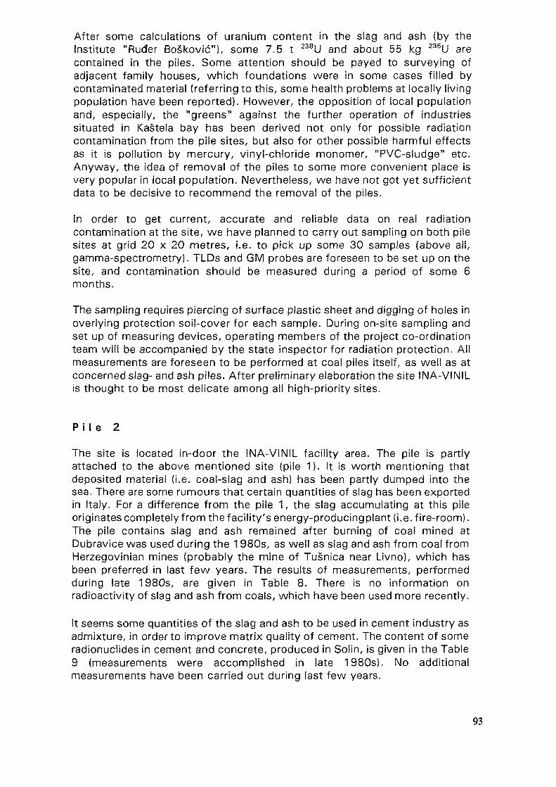
After some calculations of uranium content in the slag and ash (by theInstitute "Ruder Boskovic"), some 7.5 t 238U and about 55 kg 235U arecontained in the piles. Some attention should be payed to surveying ofadjacent family houses, which foundations were in some cases filled bycontaminated material (referring to this, some health problems at locally livingpopulation have been reported). However, the opposition of local populationand, especially, the "greens" against the further operation of industriessituated in Kastela bay has been derived not only for possible radiationcontamination from the pile sites, but also for other possible harmful effectsas it is pollution by mercury, vinyl-chloride monomer, "PVC-sludge" etc.Anyway, the idea of removal of the piles to some more convenient place isvery popular in local population. Nevertheless, we have not got yet sufficientdata to be decisive to recommend the removal of the piles.
in order to get current, accurate and reliable data on real radiationcontamination at the site, we have planned to carry out sampling on both pilesites at grid 20 x 20 metres, i.e. to pick up some 30 samples (above aii,gamma-spectrometry). TLDs and GM probes are foreseen to be set up on thesite, and contamination should be measured during a period of some 6months.
The sampling requires piercing of surface plastic sheet and digging of holes inoverlying protection soil-cover for each sample. During on-site sampling andset up of measuring devices, operating members of the project co-ordinationteam will be accompanied by the state inspector for radiation protection. AHmeasurements are foreseen to be performed at coal piles itself, as well as atconcerned slag- and ash piles. After preliminary elaboration the site INA-VINILis thought to be most delicate among all high-priority sites.
P i l e 2
The site is located in-door the INA-VINIL facility area. The pile is partlyattached to the above mentioned site (pile 1). It is worth mentioning thatdeposited material (i.e. coal-slag and ash) has been partly dumped into thesea. There are some rumours that certain quantities of slag has been exportedin Italy. For a difference from the pile 1, the slag accumulating at this pileoriginates completely from the facility's energy-producingplant (i.e. fire-room).The pile contains slag and ash remained after burning of coal mined atDubravice was used during the 1980s, as well as slag and ash from coal fromHerzegovinian mines (probably the mine of Tusnica near Livno), which hasbeen preferred in last few years. The results of measurements, performedduring late 1980s, are given in Table 8. There is no information onradioactivity of slag and ash from coals, which have been used more recently.
It seems some quantities of the slag and ash to be used in cement industry asadmixture, in order to improve matrix quality of cement. The content of someradionuclides in cement and concrete, produced in Solin, is given in the Table9 (measurements were accomplished in late 1980s). No additionalmeasurements have been carried out during last few years.
93
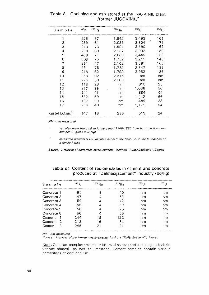
Table 8. Coal slag and ash stored at the INA-VINIL plant/former JUGOVINIL/'
S a
Kastel
m p 1 e
123456789
1011121314151617
Luksic**
40K
275259213230456308331291218358275118277241332197256
147
228Ra
5761736371754776629253233941693043
16
226Ra
1,9422,0351,9912,1572,0801,7522,1021,7821,7992,3162,203
nmnmnmnmnmnm
233
238U
3,4933,804 '3,5903,9023,4453,2113,5912,8472,952
nmnm
6101,088
8841,442
4891,171
513
235U
161175165180159148165131136nmnm285041662354
24
NM - not measured
samples were being taken in the period 1988-1990 from both the fire-roomand pile 2; given in Bq/kg)
measured material is accumulated beneath the floor, i.e. in the foundation ofa family house
Source: Archives of performed measurements, Institute "Ruder Boskovi'6", Zagreb
Table 9: Content of radionuclides in cement and concreteproduced at "Dalmacijacement" industry (Bq/kg)
S a m p 1
ConcreteConcreteConcreteConcreteConcreteConcreteCementCementCement
e
123456123
40|<
514759565056
244213246
228Ra
544444
191621
226Ra
405372697856
1228421
238 y
nmnmnmnmnmnmnmnmnm
235y
nmnmnmnmnmnmnmnmnm
NM - not measuredSource: Archives of performed measurements, Institute "Ruder BoSkovid", Zagreb
Note: Concrete samples present a mixture of cement and coal-slag and ash (invarious shares), as well as limestone. Cement samples contain variouspercentage of coal and ash.
94
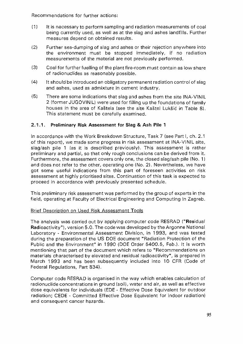
Recommendations for further actions:
(1) it is necessary to perform sampling and radiation measurements of coalbeing currently used, as well as at the slag and ashes landfills. Furthermeasures depend on obtained results.
(2) Further sea-dumping of slag and ashes or their rejection anywhere intothe environment must be stopped immediately, if no radiationmeasurements of the material are not previously performed.
(3) Coal for further fuelling of the plant fire-room must contain as low shareof radionuclides as reasonably possible.
(4) It should be introduced an obligatory permanent radiation control of slagand ashes, used as admixture in cement industry.
(5) There are some indications that slag and ashes from the site INA-VINIL2 (former JUGOVINIL) were used for filling up the foundations of familyhouses in the area of Kastela (see the site Kastel Luksic in Table 8).This statement must be carefully examined.
2.1.1. Preliminary Risk Assessment for Slag & Ash Pile 1
In accordance with the Work Breakdown Structure, Task 7 (see Part I, ch. 2.1of this report), we made some progress in risk assessment at INA-VINIL site,slag/ash pile 1 (as it is described previously). This assessment is ratherpreliminary and partial, so that only rough conclusions can be derived from it.Furthermore, the assessment covers only one, the closed slag/ash pile (No. 1)and does not refer to the other, operating one (No. 2). Nevertheless, we havegot some useful indications from this part of foreseen activities on riskassessment at highly prioritised sites. Continuation of this task is expected toproceed in accordance with previously presented schedule.
This preliminary risk assessment was performed by the group of experts in thefield, operating at Faculty of Electrical Engineering and Computing in Zagreb.
Brief Description on Used Risk Assessment Tools
The analysis was carried out by applying computer code RESRAD ("ResidualRadioactivity"), version 5.0. The code was developed by the Argonne NationalLaboratory - Environmental Assessment Division, in 1993, and was testedduring the preparation of the US DOE document "Radiation Protection of thePublic and the Environment" in 1990 (DOE Order 5400.5, Feb.). It is worthmentioning that part of the document which refers to "Recommendations onmaterials characterised by elevated and residual radioactivity", is prepared inMarch 1993 and has been subsequently included into 10 CFR (Code ofFederal Regulations, Part 834).
Computer code RESRAD is organised in the way which enables calculation ofradionuclide concentrations in ground (soil), water and air, as well as effectivedose equivalents for individuals (EDE - Effective Dose Equivalent for outdoorradiation; CEDE - Committed Effective Dose Equivalent for indoor radiation)and consequent cancer hazards.
95
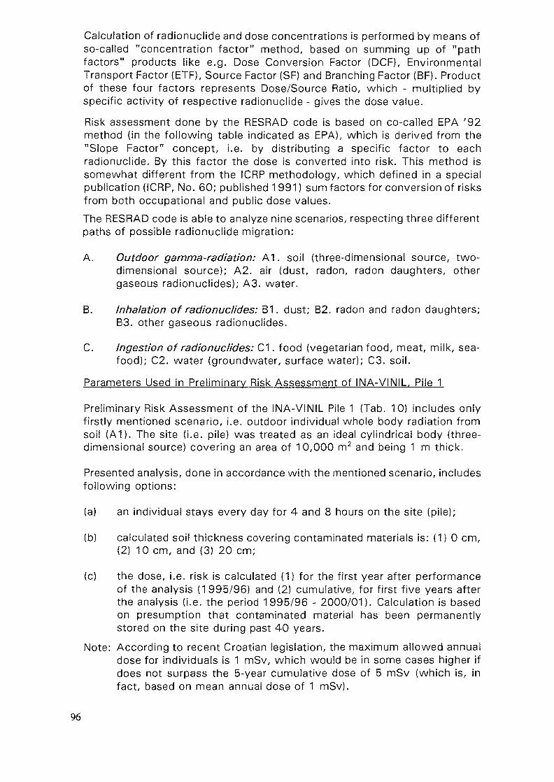
Calculation of radionuclide and dose concentrations is performed by means ofso-called "concentration factor" method, based on summing up of "pathfactors" products like e.g. Dose Conversion Factor (DCF), EnvironmentalTransport Factor (ETF), Source Factor (SF) and Branching Factor (BF). Productof these four factors represents Dose/Source Ratio, which - multiplied byspecific activity of respective radionuclide - gives the dose value.
Risk assessment done by the RESRAD code is based on co-called EPA '92method (in the following table indicated as EPA), which is derived from the"Slope Factor" concept, i.e. by distributing a specific factor to eachradionuciide. By this factor the dose is converted into risk. This method issomewhat different from the ICRP methodology, which defined in a specialpublication (ICRP, No. 60; published 1991) sum factors for conversion of risksfrom both occupational and public dose values.The RESRAD code is able to analyze nine scenarios, respecting three differentpaths of possible radionuclide migration:
A. Outdoor gamma-radiation: A1. soil (three-dimensional source, two-dimensional source); A2. air (dust, radon, radon daughters, othergaseous radionuclides); A3. water.
B. Inhalation of radionuclides: B1. dust; B2. radon and radon daughters;B3. other gaseous radionuclides.
C. Ingestion of radionuclides: C1. food (vegetarian food, meat, milk, sea-food); C2. water (groundwater, surface water); C3. soil.
Parameters Used in Preliminary Risk Assessment of INA-VINIL, Pile 1
Preliminary Risk Assessment of the INA-VINIL Pile 1 (Tab. 10) includes onlyfirstly mentioned scenario, i.e. outdoor individual whole body radiation fromsoil (A1). The site (i.e. pile) was treated as an ideal cylindrical body (three-dimensional source) covering an area of 10,000 m2 and being 1 m thick.
Presented analysis, done in accordance with the mentioned scenario, includesfollowing options:
(a) an individual stays every day for 4 and 8 hours on the site (pile);
(b) calculated soil thickness covering contaminated materials is: (1) 0 cm,(2) 10 cm, and (3) 20 cm;
(c) the dose, i.e. risk is calculated (1) for the first year after performanceof the analysis (1995/96) and (2) cumulative, for first five years afterthe analysis (i.e. the period 1995/96 - 2000/01). Calculation is basedon presumption that contaminated material has been permanentlystored on the site during past 40 years.
Note: According to recent Croatian legislation, the maximum allowed annualdose for individuals is 1 mSv, which would be in some cases higher ifdoes not surpass the 5-year cumulative dose of 5 mSv (which is, infact, based on mean annual dose of 1 mSv).
96
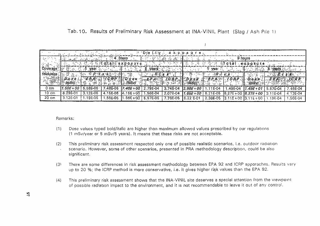
Tab. 10. Results of Preliminary Risk Assessment at INA-VINIL Plant (Slag / Ash Pile 1
t>f« DUy ;', -e -k:i M, fr** rt+i fm »-4, frn An ^ii «**• tm fftt f*
f fJ s v ^ ,. A %--% ; \\
0 cm 1.50Z+00 6.58E-05' 7.48E-05 2.79E-04 3.74E-04 2.S55+00 1.1 IE-04 1 .49E-04 6.67E-04 7.46-0410 cm 8.29E-01 3.12E-05 4.16E-05 4.15E + 00 1.56E-04 2.07E-04 6.21E-05 8.27E + 00 5.275 + 00 3.11E-04 4 1 3E-0420 cm 3.12E-01 1.19E-05 1.56E-05 1.56E + 00 5.97E-05 7.76E-05 6,22 E-01 2.38E-05 3.11E + 00 3.11E + 00 1.19E-04 1.56E-04
Remarks:
(1) Dose values typed bold/italic are higher than maximum allowed values prescribed by our regulations(1 mSv/year or 5 mSv/5 years). It means that these risks are not acceptable.
(2) This preliminary risk assessment respected only one of possible realistic scenarios, i.e. outdoor radiationscenario. However, some of other scenarios, presented in PRA methodology description, could be alsosignificant.
(3> There are some differences in risk assessment methodology between ERA 92 and ICRP apporaches. Results varyup to 20 %; the ICRP method is more conservative, i.e. it gives higher risk values than the EPA 92.
(4) This preliminary risk assessment shows that the INA-VINIL site deserves a special attention from the viewpointof possible radiation impact to the environment, and it is not recommendable to leave it out of any control.
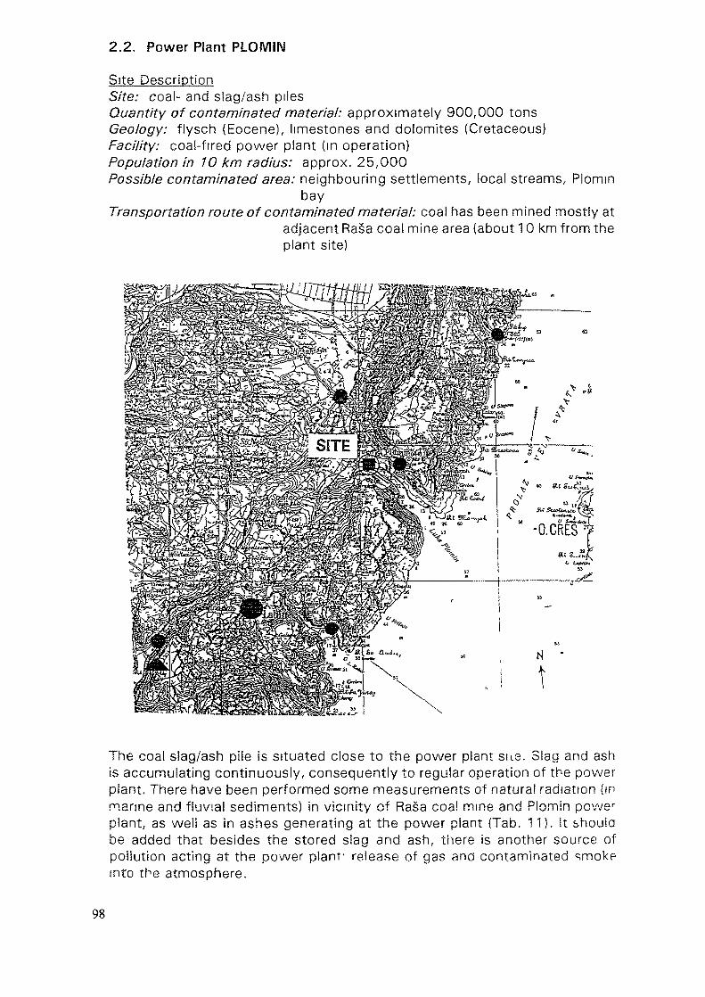
2.2. Power Plant PLOMIN
Site DescriptionSite: coal- and slag/ash pilesQuantity of contaminated material: approximately 900,000 tonsGeology: fiysch (Eocene), limestones and dolomites (Cretaceous)Facility: coal-fired power plant (in operation)Population in 10 km radius: approx. 25,000Possible contaminated area: neighbouring settlements, local streams, Plomm
bayTransportation route of contaminated material: coal has been mined mostly at
adjacent Rasa coal mine area (about 10 km from theplant site)
\
The coal slag/ash pile is situated close to the power plant sue. Slag and ashis accumulating continuously, consequently to regular operation of the powerplant. There have been performed some measurements of natural radiation (inmarine and fluvial sediments) in vicinity of Rasa coal mine and Plomin power
plant, as well as in ashes generating at the power plant (Tab. 11). it shouldbe added that besides the stored siag and ash, there is another source ofpollution acting at the power plant- release of gas and contaminated smokpinto the atmosphere.
98
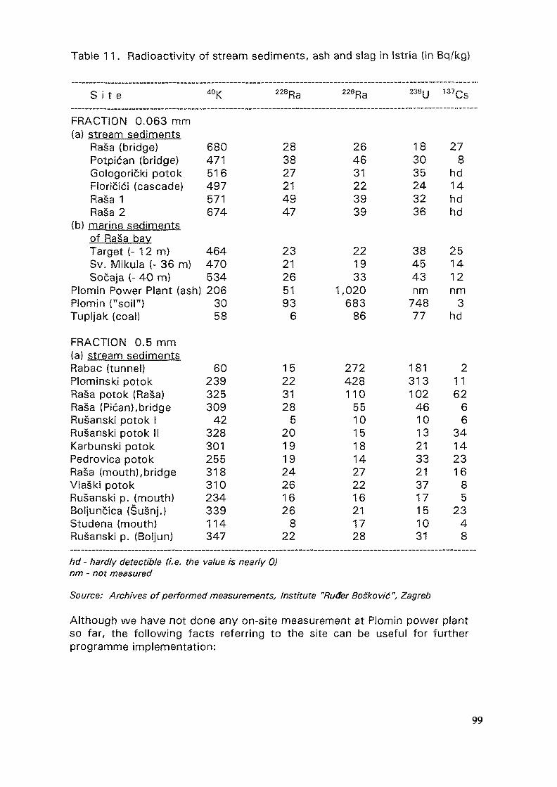
Table 11. Radioactivity of stream sediments, ash and slag in Istria (in Bq/kg)
S i t e
FRACTION 0.063 mm(a) stream sediments
Rasa (bridge)Potpican (bridge)Gologoricki potokFloricici (cascade)Rasa 1Rasa 2
(b) marine sedimentsof Rasa bayTarget ( -12m)Sv. Mikula (- 36 m)Socaja (- 40 m)
Plomin Power Plant (ash)Plomin ("soil")Tupljak (coal)
FRACTION 0.5 mm(a) stream sedimentsRabac (tunnel)Plominski potokRasa potok (Rasa)Rasa (Pican), bridgeRusanski potok IRusanski potok IIKarbunski potokPedrovica potokRasa (mouth), bridgeVlaski potokRusanski p. (mouth)Boljuncica (Susnj.)Studena (mouth)Rusanski p. (Boljun)
40K
680471516497571674
464470534206
3058
60239325309
42328301255318310234339114347
228Ra
283827214947
2321265193
6
15223128
520191924261626
822
226Ra
264631223939
221933
1,020683
86
272428110
5510151814272216211728
238y
18
3035243236
384543nm
74877
1813131024610132133213717151031
137Cs
278
hd14hdhd
251412nm
3hd
21162
66
34142316
85
2348
hd - hardly detectible (/'. e. the value is nearly 0)nm - not measured
Source: Archives of performed measurements. Institute "Ruder Bogkovic", Zagreb
Although we have not done any on-site measurement at Plomin power plantso far, the following facts referring to the site can be useful for furtherprogramme implementation:
99
(a) S/ag and ash accumulated on the site have been generated by burning ofcoal mined in Rasa coal-mine area (mines Ripenda, Tupljak, Koromacno).Unfortunately, this coal is characterised by remarkably high percentageof sulphur (up to 10-14 %) and naturally elevated share of uranium(238U).
(b) Total quantity of slag and ash which has been accumulated on the siteso far is about 900,000 tons.
(c) Past investigations [12,1 3] showed that black coa/from the Rasa mines,which was burned in the power plant Plomin I, is rich in uranium: 238Uconcentration reaches in some samples 400 ppm, i.e. specific activity of238U in this coal is up to 4,900 Bq/kg. Radium (226Ra) concentration in thecoal is 21 ppm (260 Bq/kg).
Specific activity of 238U in collected flying ash (at electro-filters) varybetween 500-8,600 Bq/kg (concentration 40-700 ppm), whilst its meanactivity is 2,260 Bq/kg. Specific activity of 226Ra in flying ash is up to2,600 Bq/kg (concentration about 210 ppm) [12,13].
Accumulated slag or "bottom ash" on the pile, which has remained afterbeing burned in the plant, is characterised by 238U specific activity 400-1,800 Bq/kg (concentration 33-147 ppm), and 226Ra specific activity 800Bq/kg (concentration 66 ppm) [12,13].
Activity of radioactive potassium f°K} and thorium (232Th), measured inslag and ash samples on the plant pile, is not remarkable and can nothave any impact to the environment and human health.
Calculations performed by the Institute "Ruder Boskovic" [12], show thatannual activity of uranium and thorium, being emitted through the plantchimney into the atmosphere, is 7.61 x 10⁸Bq.
The activity concentration of accumulated ash at the plant pile, derivedfrom specific activity of 238U, is about 1.4 x 10⁷ Bq/m3. This activityrepresents in Croatian legislation [14] just a limit value for solidradioactive waste (for alpha-emitters). However, it should be emphasisedthat requirements contained in the mentioned regulation are "mild" inrelation to current regulations of European Union countries and theUnited States. For this reason, possible radiation pollution from thePlomin power plant facility and slag/ash pile must be perceived seriously.Nevertheless, it is worth mentioning that past radiometric investigationsin Istrian peninsula [15] show at fairly high background activity in thisregion, so that e.g. the content of thorium and radium in Istrian streamsediments is remarkable.
According to another regulation [16], slag and ash collected on the plantpile are not allowed to be used as house-building material, since itsspecific activity surpasses the maximum allowed limit values (400 Bq/kgfor 226Ra).
100
(d) The slag/ash pile is situated on low permeable Eocene flysch. However,this sediment could be very easy weathered and affected by proluvialprocesses (torrents). Geological setting of the broader area ischaracterised by Mesozoic carbonates (limestones, dolomites) which aredue to irregular circulation of groundwater environmentally very sensitiveand, thus, the monitoring of radionuclides which would possibly migratein the groundwater from this pile, is not easy. Besides the immediatesurrounding area of the plant, radioactively polluted material affects alsothe zone between the plant and the seaside, as well as submarine areaof the Plomin bay.
(e) Environmental preservation and human health protection measures,performed on the site so far, have been directed basically to covering ofcontaminated materially soil and clayey material (which can remarkablyprevent ingression of rainfall into contaminated material, but also disabledeflation, i.e. blowing the material away). The existing fence surroundingthe pile is an additional protection measure: it prevents the access ofuninvited persons and possible carrying the stored material away. Finally,the pile site is provided by drainage system which considerably lowerserosional, derasional and proluvial processes, whilst retention pool -situated between the plant and the coastline - diminishes sedimentationof eroded terrestrial material (including stored slag and ash) into adjacentPlomin bay.
(f) Environmental clean-up of the site, i.e. slag/ash pile, should be based onthe above mentioned facts, but necessity of further plant operation mustbe also considered. As local coal mines has been almost exhausted, ithas been already decided that imported coal with low share of sulphurand uranium will be used as fuel for plant operation. Detailed sitecharacterisation and consequent risk assessment will show which clean-up method would be preferable for safely insulation of contaminated slagand ashes. Pile closure, conservation or removal are some of options, but- disregarding the finally chosen method - the monitoring of the siteshould start as soon as possible.
In order to identify real recent pollution, the following sampling andmeasurements are about to start:
* gamma-spectrometry and radiochemical analysis of coal-, slag- and ash-samples from the piles at the power plant;
* measurements of natural radionuclide concentrations (6 air-sampies) takeninside the 20 km radius around the power plant;
* measurements of natural radionuclide concentration in soil (4 samples)taken within the 2 km radius around the power plant;
* measurements of radionuclide concentrations in pedological horizons at fewvertical profiles (3-5 samples per profile) in order to determine verticalmigration of radionuclides (especially uranium) which could be caused byacid rains.
Finally, there has been taken into consideration measurement of possibleradiation contamination in marine sediments in the Plomin bay. This idea is
101
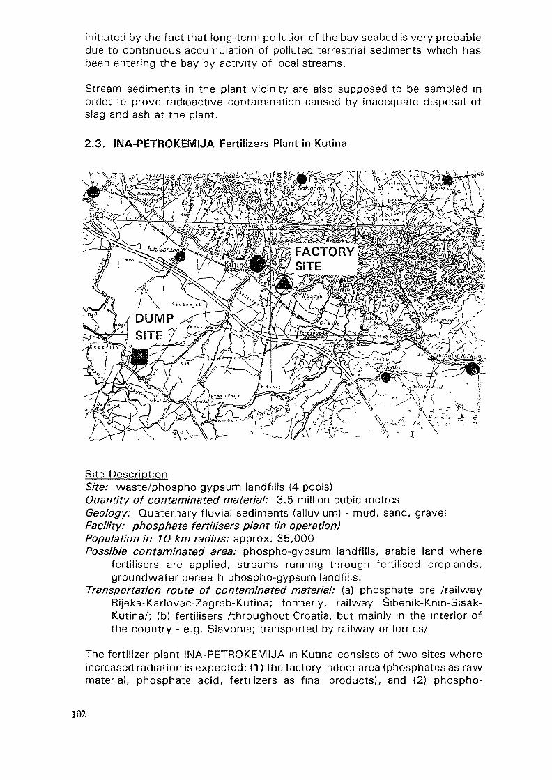
initiated by the fact that long-term pollution of the bay seabed is very probabledue to continuous accumulation of polluted terrestrial sediments which hasbeen entering the bay by activity of local streams.
Stream sediments in the plant vicinity are also supposed to be sampled inordec to prove radioactive contamination caused by inadequate disposal ofslag and ash at the plant.
2.3. INA-PETROKEMIJA Fertilizers Plant in Kutina
Site DescriptionSite: waste/phospho gypsum landfills (4 pools)Quantity of contaminated material: 3.5 million cubic metresGeology: Quaternary fluvial sediments (alluvium) - mud, sand, gravelFacility: phosphate fertilisers plant (in operation)Population in 1O km radius: approx. 35,000Possible contaminated area: phospho-gypsum landfills, arable land where
fertilisers are applied, streams running through fertilised croplands,groundwater beneath phospho-gypsum landfills.
Transportation route of contaminated material: (a) phosphate ore /railwayRijeka-Karlovac-Zagreb-Kutina; formerly, railway Sibenik-Knm-Sisak-Kutina/; (b) fertilisers /throughout Croatia, but mainly in the interior ofthe country - e.g. Slavonia; transported by railway or lorries/
The fertilizer plant INA-PETROKEMIJA in Kutina consists of two sites whereincreased radiation is expected: (1) the factory indoor area (phosphates as rawmatenai, phosphate acid, fertilizers as final products), and (2) phospho-
102
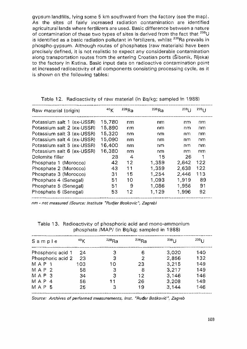
gypsum landfills, lying some 5 km southward from the factory (see the map).As the sites of fairly increased radiation contamination are identifiedagricultural lands where fertilizers are used. Basic difference between a natureof contamination of these two types of sites is derived from the fact that 238Uis identified as a basic radiation pollutant in fertilizers, whilst 226Ra prevails inphospho-gypsum. Although routes of phosphates (raw materials) have beenprecisely defined, it is not realistic to expect any considerable contaminationalong transportation routes from the entering Croatian ports (Sibenik, Rijeka)to the factory in Kutina. Basic input data on radioactive contamination pointat increased radioactivity of all components consisting processing cycle, as itis shown on the following tables:
Table 12. Radioactivity of raw material (in Bq/kg; sampled in 1988)
Raw material (origin) 40K 228Ra 226Ra 238U 235U
Potassium salt 1 (ex-USSR)Potassium salt 2 (ex-USSR)Potassium salt 3 (ex-USSR)Potassium salt 4 (ex-USSR)Potassium salt 5 (ex-USSR)Potassium salt 6 (ex-USSR)Dolomite fillerPhosphate 1 (Morocco)Phosphate 2 (Morocco)Phosphate 3 (Morocco)Phosphate 4 (Senegal)Phosphate 5 (Senegal)Phosphate 6 (Senegal)
15,78015,89015,32015,09016,40016,380
28424331515153
nmnmnmnmnmnm
412111510
912
nmnmnmnmnmnm15
1,3591,3591,2541,0931,0861,129
nmnmnmnmnmnm26
2,6422,6382,4461,9191,9561,996
nmnmnmnmnmnm
1122122113
899192
nm - not measured (Source: Institute "Rudjer Boskovic", Zagreb!
Table 13. Radioactivity of phosphoric acid and mono-ammoniumphosphate /MAP/ (in Bq/kg; sampled in 1988)
S a m p l e 40K 228Ra 226Ra 238U 235U
Phosphoric acid 1Phosphoric acid 2M A P IM A P 2M A P SM A P 4M A P 5
2423
10358345625
33
1033
113
62
238
122619
3,0202,8563,2153,2173,1463,2083,144
140132149149146149146
Source: Archives of performed measurements, Inst. "Ruder BoSkovid ", Zagreb
103
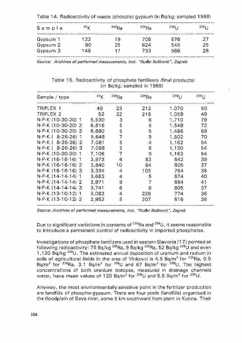
Table 14. Radioactivity of waste /phospho/ gypsum (in Bq/kg; sampled 1988)
S a m p l e 40K 228Ra 226Ra 238U 235U
Gypsum 1Gypsum 2Gypsum 3
12290148
192517
708624733
576545566
272526
Source: Archives of performed measurements, Inst. "Ruder BoSkovic", Zagreb
Table 15. Radioactivity of phosphate fertilisers /final products/(in Bq/kg; sampled in 1988}
Sample / type 40K 228Ra 226Ra 238U 235U
TRIPLEX 1TRIPLEX 2N-P-K (10-30-20) 1N-P-K (10-30-20) 2N-P-K (10-30-20) 3N-P-K ( 8-26-26) 1N-P-K ( 8-26-26) 2N-P-K ( 8-26-26) 3N-P-K (10-20-30) 1N-P-K (16-16-16) 1N-P-K (16-16-16) 2N-P-K (16-16-16) 3N-P-K (14-14-14) 1N-P-K (14-14-14) 2N-P-K (14-14-14) 3N-P-K (13-10-12) 1N-P-K (13-10-12) 2
4952
5,5306,8166,8805,6487,0817,0887,1063,9733,8403,3343,6833,9713,7413,0832,952
23223557557610449645
2122186559469
8384
105576
226207
1,0701,0591,7101,5491,4861,5021,1621,1301,163842805764874884805774816
5049797269705454543937354041373638
Source: Archives of performed measurements, Inst. "Ruder Boskovic", Zagreb
Due to significant variations in contents of 226Ra and 238U, it seems reasonableto introduce a permanent control of radioactivity in imported phosphates.
Investigations of phosphate fertilizers used in eastern Slavonia [17] pointed atfollowing radioactivity: 75 Bq/kg 226Ra, 9 Bq/kg 228Ra, 52 Bq/kg 235U and even1,120 Bq/kg 238U. The estimated annual deposition of uranium and radium insoils of agricultural fields in the area of Vinkovci is 4.5 Bq/m2 for 226Ra, 0.5Bq/m2 for 228Ra, 3.1 Bq/m2 for 235U and 67 Bq/m2 for 238U. The highestconcentrations of both uranium isotopes, measured in drainage channelswater, have mean values of 120 Bq/m3 for 238U and 5.5 Bq/m3 for 235U.
Anyway, the most environmentally sensitive point in the fertilizer productionare landfills of phospho-gypsum. There are four pools (landfills) organised inthe floodplain of Sava river, some 5 km southward from plant in Kutina. Their
104

size is 43 hectares (ha), 33 ha, 28 ha and 32 ha respectively, i.e. the landfillcovers a total surface of 136 ha. Pools are arranged along an area 1 km longand 700 m wide. Total capacity of pools is 20 million cubic metres, but only3.5 million cubic metres of phospho-gypsum have been stored so far. Wastegypsum, mixed with water, is transported from the factory to pools by specialpipeline. Radionuclide contents of phospho-gypsum itself, groundwater andwaste-water is controlled continuously (their highest concentration values aregiven above). Nevertheless, it is out of any doubt that clean-up of these pools,which are indispensable for regular operation of INA-PETROKEMUA factory,represents highly recommendable action necessary for improvement ofenvironmental quality and, consequently, human health protection. Someimprovement in fertilizer production should be also discussed since generationof 4-5 tons of phospho-gypsum (as waste material) from production of 1 tonof phosphoric acid does not seem to be reasonable and representsconsiderable ecological burden.
2.3.1. Basic Results of Measurements at INA-PETROKEMUA Plant,Done in the Frames of the Programme Performance
Most of planned data on radiation characterisation at the INA-PETROKEMUAplant indoor area in Kutina (i.e. excluding phospho-gypsum landfills) have beencollected so far (sampling and measurements were performed in the periodMarch-October 1994). Presented numerical results of the performedmeasurements are referring to the following topics:
(M 1) radiochemical analysis of 226Ra in groundwater and well-water;(M 2) radiation doses in airborne samples (measured by TLDs);(M 3) gamma-spectrometry of phosphates (raw material), fertilizers (final
products), phospho-gypsum (waste material) and airborne samples;(M 4) measurement of Working level (222Rn daughters)(M 5) sampling and measurement of radon concentrations;(M 6) estimate of 226Ra activity at the phospho-gypsum landfill;
M. 1. Radiochemical Analysis of 22sRa in Groundwater and Well-Water
CaF2-Si(OH),, /sediment/ landfill* vertical piezometer D1 112.2 +/- 12.2 mBq/l
Phospho-gvpsum landfill* horizontal piezometer D2 112.7 +/-12.2 mBq/l* vertical piezometer D3 165.9 +/- 31.5 mBq/l* vertical piezometer 87.5 +/-12.9 mBq/l* horizontal piezometer 101.4 +/-13.4 mBq/l
Well-water samples* family house in Radiceva street 388 36.5 +/- 11.4 mBq/l
105
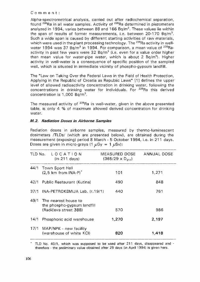
C o m m e n t :
Alpha-spectrometrical analysis, carried out after radiochemical separation,found 226Ra in all water samples. Activity of 226Ra determined in piezometersanalyzed in 1994, varies between 88 and 166 Bq/m3. These values lie withinthe span of results of former measurements, i.e. between 20-170 Bq/m3.Such a wide span is caused by different starting activities of raw materials,which were used in the plant processing technology. The 226Ra activity in well-water 1994 was 37 Bq/m3 in 1994. For comparison, a mean value of 226Ra-activity in past few years were 32 Bq/m3 (i.e. even for a value order higherthan mean value for water-pipe water, which is about 2 Bq/m3). Higheractivity in well-water is a consequence of specific position of the sampledwell, which is situated in immediate vicinity of phospho-gypsum landfill.
The "Law on Taking Over the Federal Laws in the Field of Health Protection,Applying in the Republic of Croatia as Republic Laws" [13 defines the upperlevel of allowed radioactivity concentration in drinking water, following theconcentrations in drinking water for individuals. For 226Ra this derivedconcentration is 1,000 Bq/m3.
The measured activity of 226Ra in weil-water, given in the above presentedtable, is only 4 % of maximum allowed derived concentration for drinkingwater.
M. 2. Radiation Doses in Airborne Samples
Radiation doses in airborne samples, measured by thermo-luminescentdosimeters /TLDs/ (which are presented below), are obtained during themeasurement (exposing) period 8 March - 5 October 1994, i.e. in 211 days.Doses are given in micro-grays (1 Gy = 1 Sv):
TLD No. L O C A T I O N MEASURED DOSE ANNUAL DOSE(in 211 days) (365/29 x D211)
44/1 Town Sport Hall(2,5 km from INA-P)* 101 1,271
42/1 Public Restaurant (Kutina) 490 848
37/1 INA-PETROKEMIJA Lab. (r.19/1) 440 761
49/1 The nearest house tothe phospho-gypsum landfill(Radiceva street 388) 570 986
14/1 Phosphoric acid warehouse
1 7/1 MAP/NPK - new facility(warehouse of white KCI)
1,270
820
2,197
1,418
TLD No. 40/1, which was supposed to be used after 211 days, disappeared and -therefore - the preliminary value obtained after 29 days (in April 1994) is given here.
106
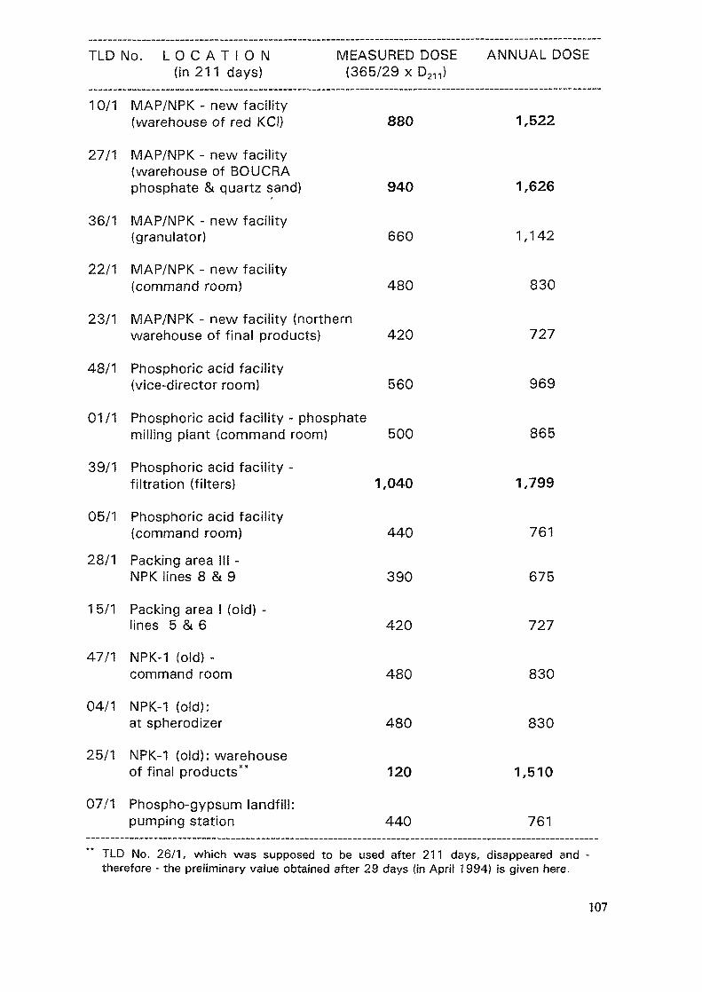
TLD No. L O C A T I O N MEASURED DOSE ANNUAL DOSE(in 211 days) (365/29 x D211)
10/1 MAP/NPK - new facility(warehouse of red KCI) 880 1,522
27/1 MAP/NPK - new facility(warehouse of BOUCRAphosphate & quartz sand) 940 1,626
36/1 MAP/NPK - new facility(granulator) 660 1,142
22/1 MAP/NPK - new facility(command room) 480 830
23/1 MAP/NPK - new facility (northernwarehouse of final products) 420 727
48/1 Phosphoric acid facility(vice-director room) 560 969
01/1 Phosphoric acid facility - phosphatemilling plant (command room) 500 865
39/1 Phosphoric acid facility -filtration (filters) 1,040 1,799
05/1 Phosphoric acid facility(command room) 440 761
28/1 Packing area Hi -NPK lines 8 & 9 390 675
15/1 Packing area I (old) -lines 5 & 6 420 727
47/1 NPK-1 (old) -command room 480 830
04/1 NPK-1 (old):at spherodizer 480 830
25/1 NPK-1 (old): warehouseof final products" 120 1,510
07/1 Phospho-gypsum landfill:pumping station 440 761
TLD No. 26/1, which was supposed to be used after 211 days, disappeared and -therefore - the preliminary value obtained after 29 days (in April 1994) is given here.
107
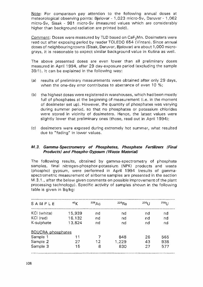
Note: For comparison pay attention to the following annual doses atmeteorological observing points: Bjelovar - 1,023 micro-Sv, Daruvar - 1,062micro-Sv, Sisak - 981 micro-Sv (measured values which are considerablyhigher than background radiation are printed bold).
Comment: Doses were measured by TLD based on CaF2Mn. Dosimeters wereread out after exposing period by reader TOLEDO 654 (Vinten). Since annualdoses of neighbouring towns (Sisak, Daruvar, Bjelovar) are about 1,000 micro-grays, it is reasonable to expect similar background value in Kutina as well.
The above presented doses are even lower than all preliminary dosesmeasured in April 1994, after 29 day-exposure period (excluding the sample39/1). It can be explained in the following way:
(a) results of preliminary measurements were obtained after only 29 days,when the one-day error contributes to aberrance of even 10 %;
(b) the highest doses were registered in warehouses, which had been mostlyfull of phosphates at the beginning of measurement (i.e. in the momentof dosimeter set up). However, the quantity of phosphates was varyingduring summer period, so that no phosphates or potassium chlorideswere stored in vicinity of dosimeters. Hence, the latest values wereslightly lower that preliminary ones (those, read out in April 1994);
(c) dosimeters were exposed during extremely hot summer, what resulteddue to "fading" in lower values.
M.S. Gamma-Spectrometry of Phosphates, Phosphate Fertilizers (FinalProducts) and Phospho-Gypsum (Waste Material)
The following results, obtained by gamma-spectrometry of phosphatesamples, final nitrogen-phosphor-potassium (NPK) products and waste(phospho) gypsum, were performed in April 1994 (results of gamma-spectrometric measurement of airborne samples are presented in the sectionM.3.1., after the below given comments on possible improvement of the plantprocessing technology). Specific activity of samples shown in the followingtable is given in Bq/kg:
S A M P L E 40K 228Ac 226Ra 235U 238U
KCI (white)KCI (red)K-suiphate
15,93916,13213,824
ndndnd
ndndnd
ndndnd
ndndnd
BQUCRA phosphatesSample 1 11 7 848 26 565Sample 2 27 12 1,229 43 938Samples 15 8 830 27 577
108
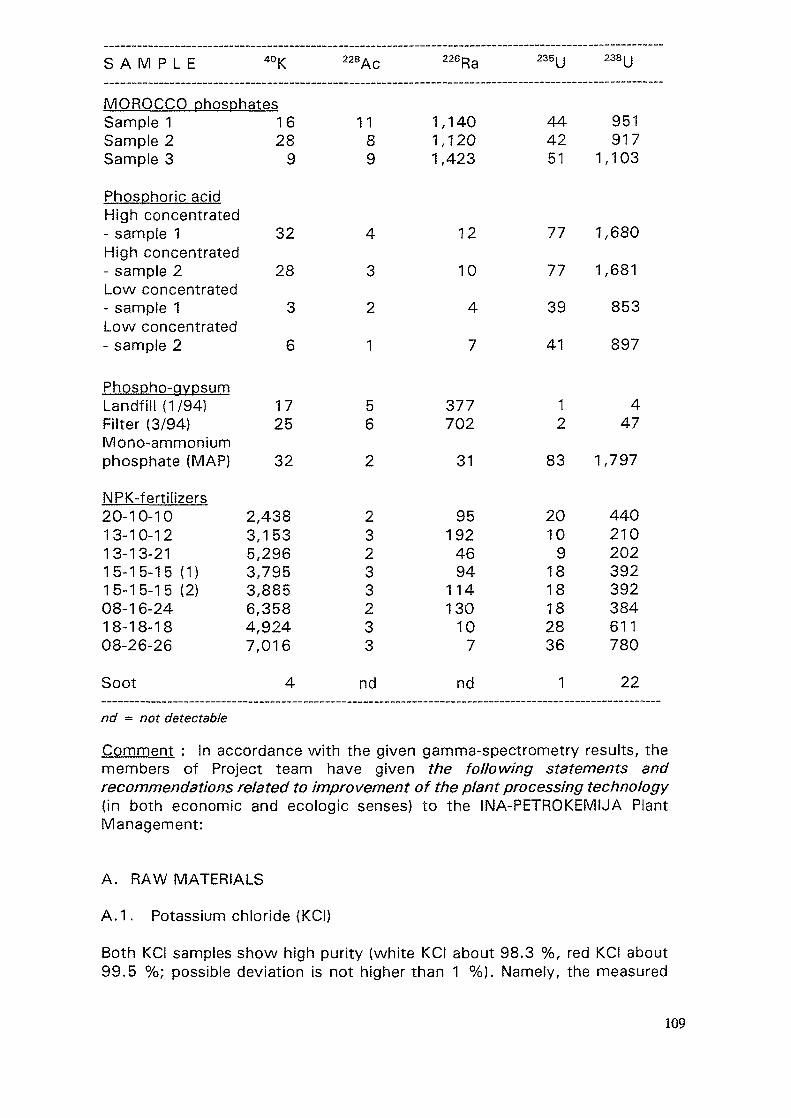
S A M P L E 40K 228Ac 226Ra 235U 238U
MOROCCO phosphatesSample 1Sample 2Sample 3
1628
9
1189
1,1401,1201,423
444251
951917
1,103
Phosphoric acidHigh concentrated- sample 1 32 4 12 77 1,680High concentrated-sample 2 28 3 10 77 1,681Low concentrated- sample 1 3 2 4 3 9 8 5 3Low concentrated- sample 2 6 1 7 4 1 8 9 7
Phospho-gypsumLandfill (1/94) 17 5 377 1 4Filter (3/94) 25 6 702 2 47Mono-ammoniumphosphate (MAP) 32 2 31 83 1,797
NPK-fertilizers20-10-10 2,438 2 95 20 44013-10-12 3,153 3 192 10 21013-13-21 5,296 2 46 9 20215-15-15 (1) 3,795 3 94 18 39215-15-15(2) 3,885 3 114 18 39208-16-24 6,358 2 130 18 38418-18-18 4,924 3 10 28 61108-26-26 7,016 3 7 36 780Soot 4 nd nd 1 22
nd = not detectable
Comment : In accordance with the given gamma-spectrometry results, themembers of Project team have given the following statements andrecommendations related to improvement of the plant processing technology(in both economic and ecologic senses) to the INA-PETROKEMIJA PlantManagement:
A. RAW MATERIALS
A.1. Potassium chloride (KCI)
Both KCI samples show high purity (white KCI about 98.3 %, red KCI about99.5 %; possible deviation is not higher than 1 %). Namely, the measured
109
specific activities of 40K are roughly identical to specific activity of chemicallypure KCI (i.e. 16,220 Bq/kg). Due to insignificant content of admixtures, allother observed radionuclides (238Ac, 226Ra, 235U, 238U) have not been detectedin any of samples.
A.2. Potassium sulphate (K2S04)
The measured specific activity of 40K in the potassium sulphate sample showsat very high purity of raw material (99.6 %, i.e. 13,824 Bq/kg in the sample,related to 13,880 Bq/kg in chemically pure potassium sulphate). Specificactivity of other observed radionuclides is equal to zero, as it was expecteddue to almost quite chemically pure sample.
Conclusion and recommendations
On the basis of the performed sampling and measurements (but referring alsoto the measurements done in the late 1980s), it is obvious that potassiumconcentrations in raw materials are in harmony with their chemicalcomposition. Further determination of potassium specific activity in potassiumsalts is not considered to be necessary, with exception of controlmeasurements if source of raw materials is changed. Potassium load degreeof agricultural lands can be simply identified and calculated in accordance withthe annual plant consumption of potassium salts alone.
A.3. Phosphates
The term "phosphates" or "phosphorites" is used for rocks abundant inphosphorus containing minerals (e.g. monazite, triphyline, copite, colinsite,lithophylite, vivianite, guanite, monetite, phylovite, pyro-phosphorite,natriphylite etc.). Main natural phosphor bearing minerals are apatite,coilophane and dalite.
Apatite, Cas(FfCI)(PO4}3, has either igneous or sedimentary origin. Apatiteconsisting igneous rocks originates through crystallization of magma as anaccessory mineral, and often presents an admixture in biotite and quartz.Apatite found in sedimentary rocks is known as basic mineral of phosphoriteand - in opposite to igneous apatite - does not include higher radionuclideconcentrations of thorium series.
Coilophane, 3Ca3(PO4)2 x n CafCO^ F2O) x H2O, is calcium-carbonate-phosphate, mostly known by amorphous structure, although there are alsosamples of crypto-crystalline coilophane. It is mainly solid, and in some casesoolitic. Mineral fragments of giauconite, carbonate and biogenous opal, as wellas remnants of organisms are often found incorporated into the mineral. It issedimentary (marine) mineral, found in phosphorites as white, yellowish-whiteto brown matrix.
Dalite, 3Ca3(PO4)2 x CaCO3, generates by recrystallisation of coilophane andis known as a crust on phosphate rocks.
110
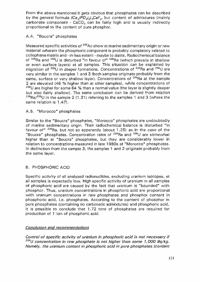
From the above mentioned it gets obvious that phosphates can be describedby the general formula (Ca3(PO4)2)3CaF2, but content of admixtures (mainlycarbonate component ~ CaC03 can be fairly high and is usually indirectlyproportional to the content of pure phosphor.
A.4. "Boucra" phosphates
Measured specific activities of 228Ac show at marine sedimentary origin or rawmaterial wherein the phosphoric component is probably completely related tocollophane matrix and - in (ess extent - maybe to dalite. Radiochemical balanceof 226Ra and 238U is disturbed "in favour of" 226Ra (which prevails in shallowor even surface layers) at all samples. This situation can be explained bymigration of 238U in deeper formations. Concentrations of 226Ra and 238U arevery similar in the samples 1 and 3 (both samples originate probably from thesame, surface or very shallow layer). Concentrations of 226Ra at the sample2 are elevated (46 % higher than at other samples), while concentrations of238U are higher for some 64 % than a normal value (the layer is slightly deeperbut also fairly shallow). The same conclusion can be derived from relation226Ra/r238y jn foe samp|e 2 (1.31) referring to the samples 1 and 3 (where thesame relation is 1.47).
A.5. "Morocco" phosphates
Similar to the "Boucra" phosphates, "Morocco" phosphates are undoubtedlyof marine sedimentary origin. Their radiochemical balance is disturbed "infavour of" 226Ra, but not so apparently (about 1.25) as in the case of the"Boucra" phosphates. Concentration rates of 226Ra and 238U are somewhathigher than at "Boucra" phosphates, but they are considerably lower inrelation to concentrations measured in late 1980s at "Morocco" phosphates.In distinction from the sample 3, the samples 1 and 2 originate probably fromthe same layer.
B. PHOSPHORIC ACID
Specific activity of all analyzed radionuclides, excluding uranium isotopes, atall samples is expectedly low. High specific activity of uranium in all samplesof phosphoric acid are caused by the fact that uranium is "bounded" withphosphor. Thus, uranium concentrations in phosphoric acid are proportionalwith uranium concentrations in raw phosphates and phosphor content inphosphoric acid, i.e. phosphates. According to the content of phosphor inpure phosphates (containing no carbonatic admixtures) and phosphoric acid,it is possible to conclude that 1.72 tons of phosphates are required forproduction of 1 ton of phosphoric acid.
Conclusion and recommendations
Control of specific activity of uranium in phosphoric acid is not necessary if238U concentration in raw phosphate is not higher than some 1,000 Bq/kg.Namely, the uranium content in phosphoric acid in pure phosphates (content
111
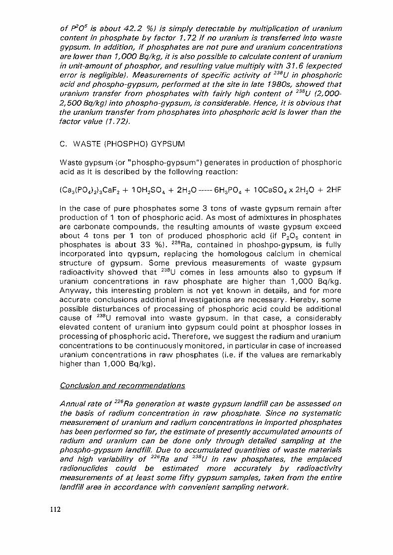
of P2OS AS about 42.2 %) is simply detectable by multiplication of uraniumcontent in phosphate by factor 1.72 if no uranium is transferred into wastegypsum. In addition, if phosphates are not pure and uranium concentrationsare lower than 1,000 Bq/kg, it is also possible to calculate content of uraniumin unit-amount of phosphor, and resulting value multiply with 31.6 (expectederror is negligible). Measurements of specific activity of 238U in phosphoricacid and phospho-gypsum, performed at the site in fate 1980s, showed thaturanium transfer from phosphates with fairly high content of 238U (2,000-2,500 Bq/kg) into phospho-gypsum, is considerable. Hence, it is obvious thatthe uranium transfer from phosphates into phosphoric acid is lower than thefactor value (1.72).
C. WASTE (PHOSPHO) GYPSUM
Waste gypsum (or "phospho-gypsum") generates in production of phosphoricacid as it is described by the following reaction:
(Ca3(P04)2}3CaF2 + 10H2SO4 + 2H20 — -6H3P04 + 10CaSO4x2H20 + 2HF
In the case of pure phosphates some 3 tons of waste gypsum remain afterproduction of 1 ton of phosphoric acid. As most of admixtures in phosphatesare carbonate compounds, the resulting amounts of waste gypsum exceedabout 4 tons per 1 ton of produced phosphoric acid (if P2O5 content inphosphates is about 33 %). 226Ra, contained in phoshpo-gypsum, is fullyincorporated into qypsum, replacing the homologous calcium in chemicalstructure of gypsum. Some previous measurements of waste gypsumradioactivity showed that 238U comes in less amounts also to gypsum ifuranium concentrations in raw phosphate are higher than 1,000 Bq/kg.Anyway, this interesting problem is not yet known in details, and for moreaccurate conclusions additional investigations are necessary. Hereby, somepossible disturbances of processing of phosphoric acid could be additionalcause of 238U removal into waste gypsum. In that case, a considerablyelevated content of uranium into gypsum could point at phosphor losses inprocessing of phosphoric acid. Therefore, we suggest the radium and uraniumconcentrations to be continuously monitored, in particular in case of increaseduranium concentrations in raw phosphates (i.e. if the values are remarkablyhigher than 1,000 Bq/kg).
Conclusion and recommendations
Annual rate of 226Ra generation at waste gypsum landfill can be assessed onthe basis of radium concentration in raw phosphate. Since no systematicmeasurement of uranium and radium concentrations in imported phosphateshas been performed so far, the estimate of presently accumulated amounts ofradium and uranium can be done only through detailed sampling at thephospho-gypsum landfill. Due to accumulated quantities of waste materialsand high variability of 226Ra and 238U in raw phosphates, the emplacedradionuclides could be estimated more accurately by radioactivitymeasurements of at least some fifty gypsum samples, taken from the entirelandfill area in accordance with convenient sampling network.
112
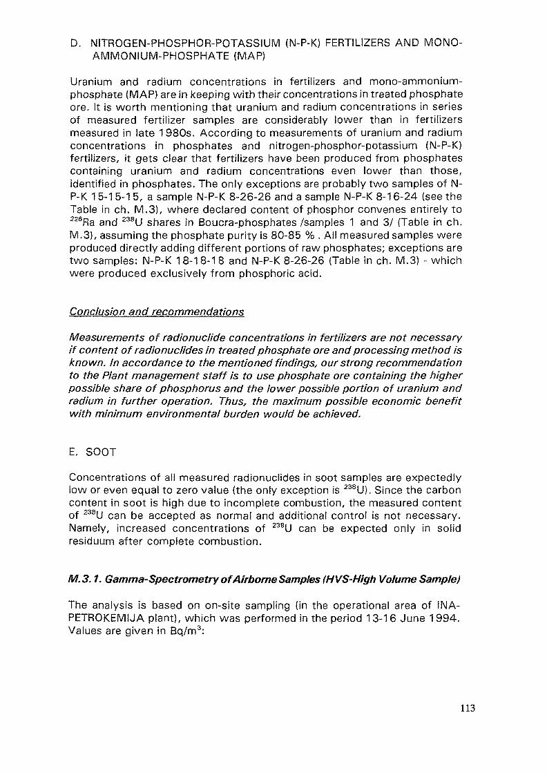
D. NITROGEN-PHOSPHOR-POTASSIUM (N-P-K) FERTILIZERS AND MONO-AMMONIUM-PHOSPHATE (MAP)
Uranium and radium concentrations in fertilizers and mono-ammonium-phosphate (MAP) are in keeping with their concentrations in treated phosphateore. It is worth mentioning that uranium and radium concentrations in seriesof measured fertilizer samples are considerably lower than in fertilizersmeasured in late 1980s. According to measurements of uranium and radiumconcentrations in phosphates and nitrogen-phosphor-potassium (N-P-K)fertilizers, it gets clear that fertilizers have been produced from phosphatescontaining uranium and radium concentrations even lower than those,identified in phosphates. The only exceptions are probably two samples of N-P-K 1 5-1 5-1 5, a sample N-P-K 8-26-26 and a sample N-P-K 8-16-24 (see theTable in ch. M.3), where declared content of phosphor convenes entirely to226Ra and 238U shares in Boucra-phosphates/samples 1 and 3/ (Table in ch.M.3), assuming the phosphate purity is 80-85 % . All measured samples wereproduced directly adding different portions of raw phosphates; exceptions aretwo samples: N-P-K 18-18-18 and N-P-K 8-26-26 (Table in ch. M.3) - whichwere produced exclusively from phosphoric acid.
Conclusion and recommendations
Measurements of radionuclide concentrations in fertilizers are not necessaryif content of radionuclides in treated phosphate ore and processing method isknown. In accordance to the mentioned findings, our strong recommendationto the Plant management staff is to use phosphate ore containing the higherpossible share of phosphorus and the lower possible portion of uranium andradium in further operation. Thus, the maximum possible economic benefitwith minimum environmental burden would be achieved.
E. SOOT
Concentrations of ali measured radionuclides in soot samples are expectedlylow or even equal to zero value (the only exception is 238U). Since the carboncontent in soot is high due to incomplete combustion, the measured contentof 238U can be accepted as normal and additional control is not necessary.Namely, increased concentrations of 238U can be expected only in solidresiduum after complete combustion.
M.S. 1. Gamma-Spectrometry of Airborne Samples (HVS-Hlgh Volume Sample)
The analysis is based on on-site sampling (in the operational area of INA-PETROKEMIJA plant), which was performed in the period 13-16 June 1 994.Values are given in Bq/m3:
113
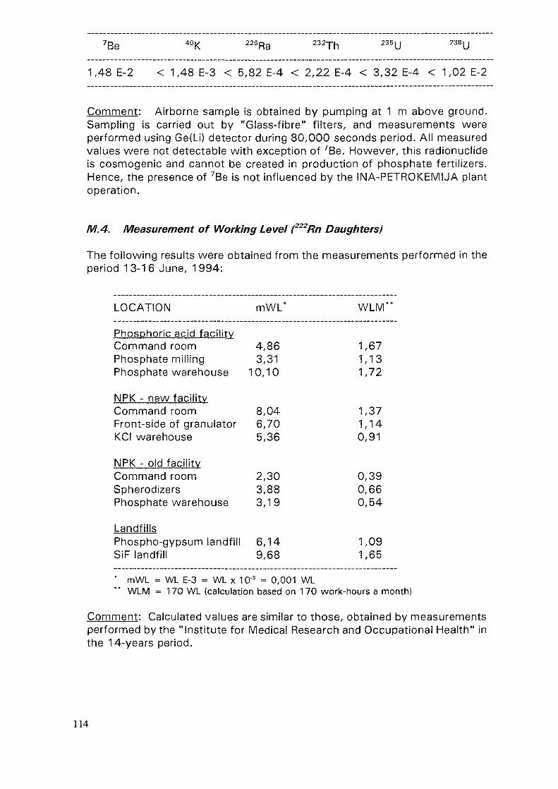
7Be 40K 226Ra 232Th 235y 238u
1,48 E-2 < 1,48 E-3 < 5,82 E-4 < 2,22 E-4 < 3,32 E-4 < 1,02 E-2
Comment: Airborne sample is obtained by pumping at 1 m above ground.Sampling is carried out by "Glass-fibre" filters, and measurements wereperformed using Ge{Li) detector during 80,000 seconds period. Ail measuredvalues were not detectable with exception of 7Be. However, this radionuclideis cosmogenic and cannot be created in production of phosphate fertilizers.Hence, the presence of 7Be is not influenced by the INA-PETROKEMUA plantoperation.
M.4. Measurement of Working Level (222Rn Daughters)
The following results were obtained from the measurements performed in theperiod 13-16 June, 1994:
LOCATION mWL* WLM**
Phosphoric acid facilityCommand roomPhosphate millingPhosphate warehouse
NPK - new facilityCommand roomFront-side of granulatorKCI warehouse
NPK - old facilityCommand roomSpherodizersPhosphate warehouse
LandfillsPhospho-gypsum landfillSiF landfill
4,863,31
10,10
8,046,705,36
2,303,883,19
6,149,68
1,671,131,72
1,371,140,91
0,390,660,54
1,091,65
* mWL = WL E-3 = WL x 10'3 = 0,001 WLWLM = 170 WL (calculation based on 170 work-hours a month)
Comment: Calculated values are similar to those, obtained by measurementsperformed by the "Institute for Medical Research and Occupational Health" inthe 14-years period.
114
M.S. Sampling and Measurement of Radon Concentrations
Following values are obtained by sampling carried out in the period March-October 1994:
LOCATION CONCENTRATION (Bq m'3)
01 Phosphate warehouse 165 + / -703 MAP/NPK: New facility - phosphate warehouse 2004 MAP/NPK: Granulator 5305 MAP/NPK: Command room 25 +/- 3*06 MAP/NPK: North warehouse 12207 Phosphoric acid facility: Office 1 9 + / - 208 Phosphoric acid facility: Phosphate milling
- command room 1 309 Phosphoric acid facility: Filtration 1210 Phosphoric acid facility: Command room 12 +/- 214 NPK-1 (old facility) - at spherodizer 121 +/- 632/1 Package room 1 (old): line 5/6 detector damaged38/1 Package room 3: NPK lines 8,9 detector damaged
Laboratory (room 19/1) 26 +/- 1Restaurant 53 -f/- 2
Measured by detector placed in diffusion chamber.
C o m m e n t :
Radon detectors (open and placed in diffusion chambers) were set up inchosen indoor places of the "INA-PETROKEMIJA" Plant in March 1994. Radonmeasurements were performed by solid detectors containing films KODAK LR-115. These detectors enable measuring of radon concentrations, as well ascalculation of risks from radon inhalation by occupational population.
On the basis of surficial trace density on open detectors, which were exposedfor a month, specific activity of radon varied between 12-123 Bq/m3. For amore accurate estimate of radon concentration, open (cassette) and sealeddetectors (diffusion chambers) have been exposed for a longer period -approximately for 7 months. Namely, the estimate of received dose foroccupational population was made possible by reading out of two detectors.Obtained data (few films have been unfortunately lost) show at somewhatelevated radon concentrations at three measuring points, but they are allremarkably below the allowed limits for working areas.
Recent ICRP recommendations for limits of specific radon indoor activity (ICRP65, [18]) define the "action level", i.e. the radon activity which requiresadditional measures to be decreased. The action level for resident areas
115
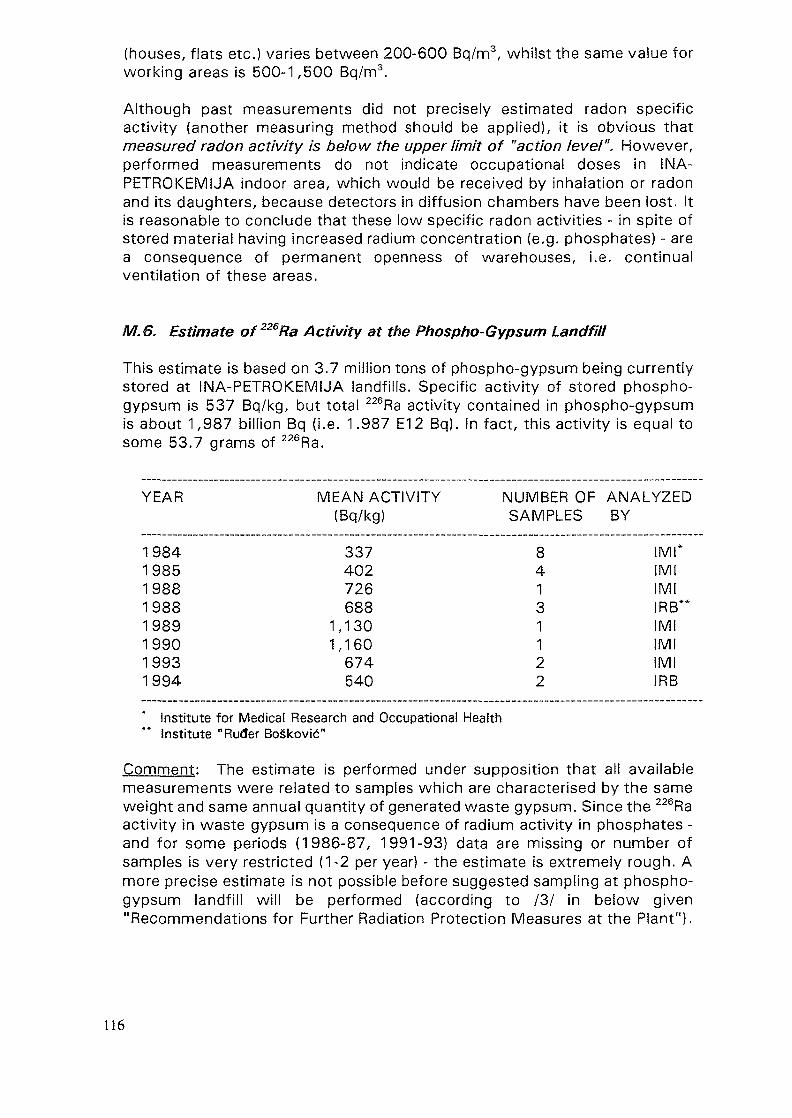
(houses, flats etc.) varies between 200-600 Bq/m3, whilst the same value forworking areas is 500-1,500 Bq/m3.
Although past measurements did not precisely estimated radon specificactivity (another measuring method should be applied), it is obvious thatmeasured radon activity is below the upper limit of "action level". However,performed measurements do not indicate occupational doses in INA-PETROKEMIJA indoor area, which would be received by inhalation or radonand its daughters, because detectors in diffusion chambers have been lost. Itis reasonable to conclude that these low specific radon activities - in spite ofstored material having increased radium concentration (e.g. phosphates) - area consequence of permanent openness of warehouses, i.e. continualventilation of these areas.
M. 6. Estimate of 226Ra Activity at the Phospho-Gypsum Landfill
This estimate is based on 3.7 million tons of phospho-gypsum being currentlystored at INA-PETROKEMIJA landfills. Specific activity of stored phospho-gypsum is 537 Bq/kg, but total 226Ra activity contained in phospho-gypsumis about 1,987 billion Bq (i.e. 1.987 E12 Bq). In fact, this activity is equal tosome 53.7 grams of 226Ra.
YEAR MEAN ACTIVITY NUMBER OF ANALYZED(Bq/kg) SAMPLES BY
19841985198819881989199019931994
337402726688
1,1301,160674540
84131122
I Ml"IMIIMIIRB"IMIIMIIMIIRB
Institute for Medical Research and Occupational HealthInstitute "Ruder Boskovid"
Comment: The estimate is performed under supposition that all availablemeasurements were related to samples which are characterised by the sameweight and same annual quantity of generated waste gypsum. Since the 226Raactivity in waste gypsum is a consequence of radium activity in phosphates -and for some periods (1986-87, 1991-93) data are missing or number ofsamples is very restricted (1-2 per year) - the estimate is extremely rough. Amore precise estimate is not possible before suggested sampling at phospho-gypsum landfill will be performed (according to /3/ in beiow given"Recommendations for Further Radiation Protection Measures at the Plant").
116
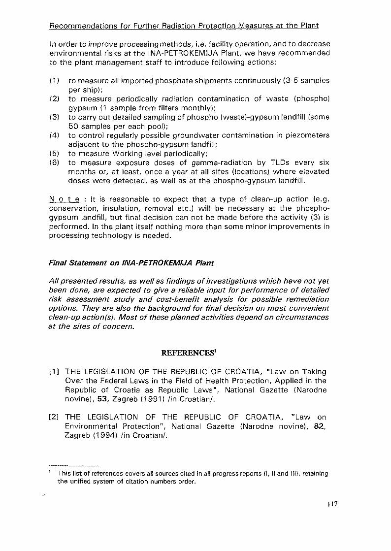
Recommendations for Further Radiation Protection Measures at the Plant
In order to improve processing methods, i.e. facility operation, and to decreaseenvironmental risks at the INA-PETROK.EMUA Plant, we have recommendedto the plant management staff to introduce following actions:
(1) to measure all imported phosphate shipments continuously (3-5 samplesper ship);
(2) to measure periodically radiation contamination of waste (phospho)gypsum (1 sample from filters monthly);
(3) to carry out detailed sampling of phospho (waste)-gypsum landfill (some50 samples per each pool);
(4) to control regularly possible groundwater contamination in piezometersadjacent to the phospho-gypsum landfill;
(5) to measure Working level periodically;(6) to measure exposure doses of gamma-radiation by TLDs every six
months or, at least, once a year at all sites (locations) where elevateddoses were detected, as well as at the phospho-gypsum landfill.
N o t e : It is reasonable to expect that a type of clean-up action (e.g.conservation, insulation, removal etc.) will be necessary at the phospho-gypsum landfill, but final decision can not be made before the activity (3) isperformed. In the plant itself nothing more than some minor improvements inprocessing technology is needed.
Final Statement on INA-PETROKEMIJA Plant
All presented results, as well as findings of investigations which have not yetbeen done, are expected to give a reliable input for performance of detailedrisk assessment study and cost-benefit analysis for possible remediationoptions. They are also the background for final decision on most convenientclean-up action(s). Most of these planned activities depend on circumstancesat the sites of concern.
REFERENCES1
[1] THE LEGISLATION OF THE REPUBLIC OF CROATIA, "Law on TakingOver the Federal Laws in the Field of Health Protection, Applied in theRepublic of Croatia as Republic Laws", National Gazette (Narodnenovine), 53, Zagreb (1991) /in Croatian/.
[2] THE LEGISLATION OF THE REPUBLIC OF CROATIA, "Law onEnvironmental Protection", National Gazette (Narodne novine), 82,Zagreb (1994} /in Croatian/.
1 This list of references covers all sources cited in all progress reports (I, II and 111), retainingthe unified system of citation numbers order.
117
[3] THE LEGISLATION OF THE REPUBLIC OF CROATIA, "Law on WasteManagement", National Gazette (Narodne novine), 34, Zagreb (1 995) /inCroatian/.
[4] THE LEGISLATION OF THE U.S.A., Office of the Federal Register, "10Code of Federal Regulations (10 CFR)", Parts 0 to 50, US GovernmentPrinting Office, Washington, D.C. (1993).
[5] THE LEGISLATION OF THE REPUBLIC OF CROATIA, "Code of Practiceon Maximum Limits of Radioactive Contamination of the Environmentand Performance of Decontamination", Official Gazette of SFRY, 8,/accepted as temporary applying regulation in the Republic of Croatia/(1987) /in Croatian/.
[6] THE LEGISLATION OF THE REPUBLIC OF CROATIA, Law on AirProtection, National Gazette (Narodne novine), 30, 72, Zagreb (1 994) /inCroatian/.
[7] THE OECD RECOMMENDATIONS, "Exposure to Radiation from theNatural Radioactivity in Building Materials", Report by the Group ofExperts of the OECD, OECD, Paris (1979).
[8] THE LEGISLATION OF THE REPUBLIC OF CROATIA, "The Law onIonising Radiation Protection and Special Safety Measures Related to Useof Atomic Energy", Official Gazette of SFRY, 62 /accepted as temporaryapplying law in the Republic of Croatia/ (1984) /in Croatian/.
[9] SUBASIC, D., SALER, A., "The Challenges and Issues Facing theRadioactive Waste Management in Croatia", Waste ManagementSymposia '94, Proceedings, Vol. 1, Tucson (1994), 181-185.
[10] "RAPAT Mission to Croatia", Travel Report, 28 June - 2 July 1993,(TA #931010243), IAEA, Vienna (1993), 1-17.
[11] SMITH, A.L., "Radioactive Scale Formation", Journal of PetroleumTechnology, 39 (1987) 607-706.
[12] "Calculation of Emissions of Radioactive Elements and Heavy Metals (atPlomin Power Plant) Based on Measurements of Concentrations in Ash,Air and Water", Institute "Ruder Boskovic", Zagreb (1984), 1-117 /inCroatian/.
[13] "Report on Coal and Ash Capability for Uranium Extraction in 1980",institute "Ruder Boskovic", Zagreb (1981), 1-74 /in Croatian/.
[14] THE LEGISLATION OF THE REPUBLIC OF CROATIA, "Code of Practiceon Methods of Collecting, Account, Processing, Storing, Final Disposaland Release of Radioactive Waste Substances in the Environment",Official Gazette of SFRY, 40 /accepted as temporary applying regulationin the Republic of Croatia/ (1986) /in Croatian/.
118
[15] BARISIC, D., "Radioactivity of Soils in Istrian Peninsula", thesis,University of Zagreb, Zagreb (1993).
[16] THE LEGISLATION OF THE REPUBLIC OF CROATIA, "Code of Practiceon Maximum Allowed Limit Values of Environmental RadiationContamination and Decontamination", Official Gazette, 8 /accepted astemporary applying regulation in the Republic of Croatia/ (1987) /inCroatian/.
[17] BARISIC", D., LULIC", S., MILETlC, P., "Radium and Uranium in PhosphateFertilizers and Their Impact on the Radioactivity of Waters", WaterResources, Vol. 26, 5, United Kingdom (1992), 697-706.
[18] "Protection against Radon-222 at Home and Work", ICRP Publication 65,(ICRP 65), International Commission for Radiation Protection, PergamonPress, Oxford-New York (1993).
119
TECHNOLOGIES FOR AND IMPLEMENTATIONOF ENVIRONMENTAL RESTORATION IN THEURANIUM INDUSTRY IN CZECH REPUBLIC
P. ANDEL, V. PRIBANMEGA - Institute for Research and Development,Strai pod Raiskem,Czech Republic
Abstract
This contribution is a logical continuation of the first andthe second parts of the Regional Technical Cooperation Project onEnvironmental Restoration in Central and Eastern Europe. Thefirst part was concentrated on identification and radiologicalcharacterization of contaminated sites (Budapest 1993); thesecond part, then, on planning for environmental restoration(Piestany 1994);this third part has been directed to particulartechnologies for environmental restoration. Problems of uraniumindustry only has been dealt in this contribution.
As documented in the previous parts, protection of water isthe fundamental problem in the field of environment protection inthe uranium industry. This is the reason why we have concentratedour attention to main technologies which are used fordecontamination of water in the uranium industry in the CzechRepublic.
l. Types of water
By origin, water may be divided into two main groups:
1) Water connected with classic mining technology and uraniumprocessing (mining and milling). This kind of water is dividedto the mine water and to the free tailing water. The minewater has been cleaned by means of decontamination plants atentire mines of the uranium industry. We present here in thiscontribution the Central Decontamination Plant which belongsto the deposit called Hamr as a representative ofdecontamination plants because that is the biggest and themost complete plant. Combined technology of electrodialysisand evaporation at the processing plant in Dolni Rozinka has
121
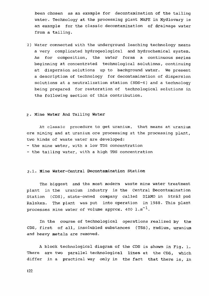
been chosen as an example for decontamination of the tailingwater. Technology at the processing plant MAPE in Mydlovary isan example for the classic decontamination of drainage waterfrom a tailing.
2) Water connected with the underground leaching technology meansa very complicated hydrogeological and hydrochemical system.As for composition, the water forms a continuous seriesbeginning at concentrated technological solutions, continuingat dispersion solutions up to background water. We presenta description of technology for decontamination of dispersionsolutions at a neutralization station (NDS-6) and a technologybeing prepared for restoration of technological solutions inthe following section of this contribution.
2 - Mine Water And Tailing Water
At classic procedure to get uranium, that means at uraniumore mining and at uranium ore processing at the processing plant,two kinds of waste water are developed:- the mine water, with a low TDS concentration- the tailing water, with a high TDS concentration
2.1. Mine Water-Central Decontamination Station
The biggest and the most modern waste mine water treatmentplant in the uranium industry is the Central DecontaminationStation (CDS), state-owned company called DIAMO in Straz podRalskem. The plant was put into operation in 1988. This plantprocesses mine water of volume approx. 400 l.s"1.
In the course of technological operations realized by theCDS, first of all, insolubled substances (TSS), radium, uraniumand heavy metals are removed.
A block technological diagram of the CDS is shown in Fig. 1.There are two parallel technological lines at the CDS, whichdiffer in a practical way only in the fact that there is, in
122
BaCI2
MINEWATER
\ r
HOMOGENIZATION
Ca(OH)2 Flocculant
SEDIMENTATIONTANK
] r
' b».ifFLOCCULATION
TANK\ r
w_V
CLARIFIER fenWSAND
FILTERS
Transportto putaway
FILTER PRESS SLUDGESEDIMENTATION
SLUDGE
RECIPIENTTHE PLOU6NICE RIVER
RETENTIONTANK
— g Line B~^ Line A^
RESINFILTERS < ———— '
FIG. 1 BLOCK TECHNOLOGICAL DIAGRAM : CDS
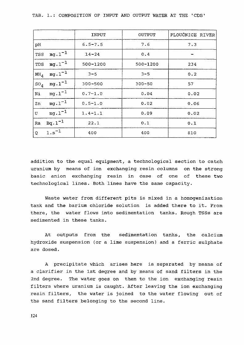
TAB. 1.: COMPOSITION OF INPUT AND OUTPUT WATER AT THE 'CDS'
pHTSS mg.l"1
TDS mg.l"1
NH4 mg.l"1
SO4 mg.l"1
Ni mg.l"1
Zn mg.l"1
U mg.l"1
Ra Bq.l"1
Q l.s"1
INPUT6.5-7.514-24
500-12003-5
300-500
0.7-1.0
0.5-1.01.4-1.1
22.1400
OUTPUT7.6
0.4
500-12003-5
300-500.040.020.090.1400
PLOUCNICE RIVER
7.3-
2340.2570.020.060.020.1810
addition to the equal equipment, a technological section to catchuranium by means of ion exchanging resin columns on the strongbasic anion exchanging resin in case of one of these twotechnological lines. Both lines have the same capacity.
Waste water from different pits is mixed in a homogenizationtank and the barium chloride solution is added there to it. Fromthere, the water flows into sedimentation tanks. Rough TSSs aresedimented in these tanks.
At outputs from the sedimentation tanks, the calciumhydroxide suspension (or a lime suspension) and a ferric sulphateare dosed.
A precipitate which arises here is separated by means ofa clarifier in the 1st degree and by means of sand filters in the2nd degree. The water goes on then to the ion exchanging resinfilters where uranium is caught. After leaving the ion exchangingresin filters, the water is joined to the water flowing out ofthe sand filters belonging to the second line.
124
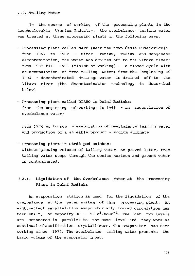
2 - 2. Tailing Water
In the course of working of the processing plants in theCzechoslovakia Uranium Industry, the overbalance tailing waterwas treated at three processing plants in the following ways:
- Processing plant called MAPE (near the town Ceske Budejovice):from 1962 to 1982 - after uranium, radium and manganesedecontamination, the water was drained-off to the Vltava river;from 1982 till 1991 (finish of working) - a closed cycle withan accumulation of free tailing water; from the beginning of1994 - decontaminated drainage water is drained off to theVltava river (the decontamination technology is describedbelow)
- Processing plant called DIAMO in Dolni Rozinka:from the beginning of working in 1968 - an accumulation ofoverbalance water;
from 1974 up to now - evaporation of overbalance tailing waterand production of a saleable product - sodium sulphate
- Processing plant in Straz pod Ralskem:without growing volumes of tailing water. As proved later, freetailing water seeps through the coniac horizon and ground wateris contaminated.
2.2.1. Liquidation of the Overbalance Water at the ProcessingPlant in Dolni Rozinka
An evaporation station is used for the liquidation of theoverbalance at the water system of this processing plant. Aneight-effect parallel-flow evaporator with forced circulation hasbeen built, of capacity 30 - 50 m3.hour-1. The last two levelsare connected in parallel to the same level and they work ascontinual classification crystallizers. The evaporator has beenworking since 1972. The overbalance tailing water presents thebasic volume of the evaporator input.
125
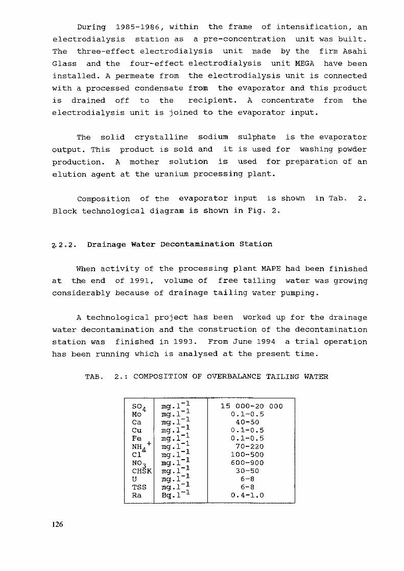
During 1985-1986, within the frame of intensification, anelectrodialysis station as a pre-concentration unit was built.The three-effect electrodialysis unit made by the firm AsahiGlass and the four-effect electrodialysis unit MEGA have beeninstalled. A permeate from the electrodialysis unit is connectedwith a processed condensate from the evaporator and this productis drained off to the recipient. A concentrate from theelectrodialysis unit is joined to the evaporator input.
The solid crystalline sodium sulphate is the evaporatoroutput. This product is sold and it is used for washing powderproduction. A mother solution is used for preparation of anelution agent at the uranium processing plant.
Composition of the evaporator input is shown in Tab. 2.Block technological diagram is shown in Fig. 2.
2-2,2. Drainage Water Decontamination Station
When activity of the processing plant MAPE had been finishedat the end of 1991, volume of free tailing water was growingconsiderably because of drainage tailing water pumping.
A technological project has been worked up for the drainagewater decontamination and the construction of the decontaminationstation was finished in 1993. From June 1994 a trial operationhas been running which is analysed at the present time.
TAB. 2.: COMPOSITION OF OVERBALANCE TAILING WATER
so4MoCaCuFeNH +ClNO3CHSKUTSSRa
mg.l~!mg. 1"mg.l"!mg.l"!mg. 1mg.l"!mg.l"!mg.l !mg.l_!mg. 1mg. 1Bq.l"1
15 000-20 0000.1-0.540-500.1-0.50.1-0.570-220100-500600-90030-506-86-8
0.4-1.0
126
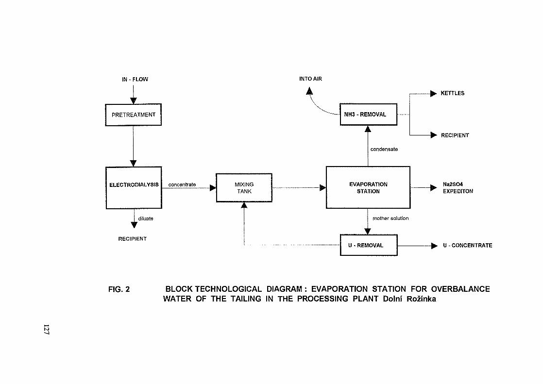
IN - FLOW
PRETREATMENT
ELECTRODIALYSIS concentrate MIXINGTANK
I diluate
RECIPIENT
INTO AIR
NH3 - REMOVAL
condensate
EVAPORATIONSTATION
mother solution
U- REMOVAL
KETTLES
RECIPIENT
Na2SO4EXPEDITON
U-CONCENTRATE
FIG. 2 BLOCK TECHNOLOGICAL DIAGRAM : EVAPORATION STATION FOR OVERBALANCEWATER OF THE TAILING IN THE PROCESSING PLANT Dolni Rozinka
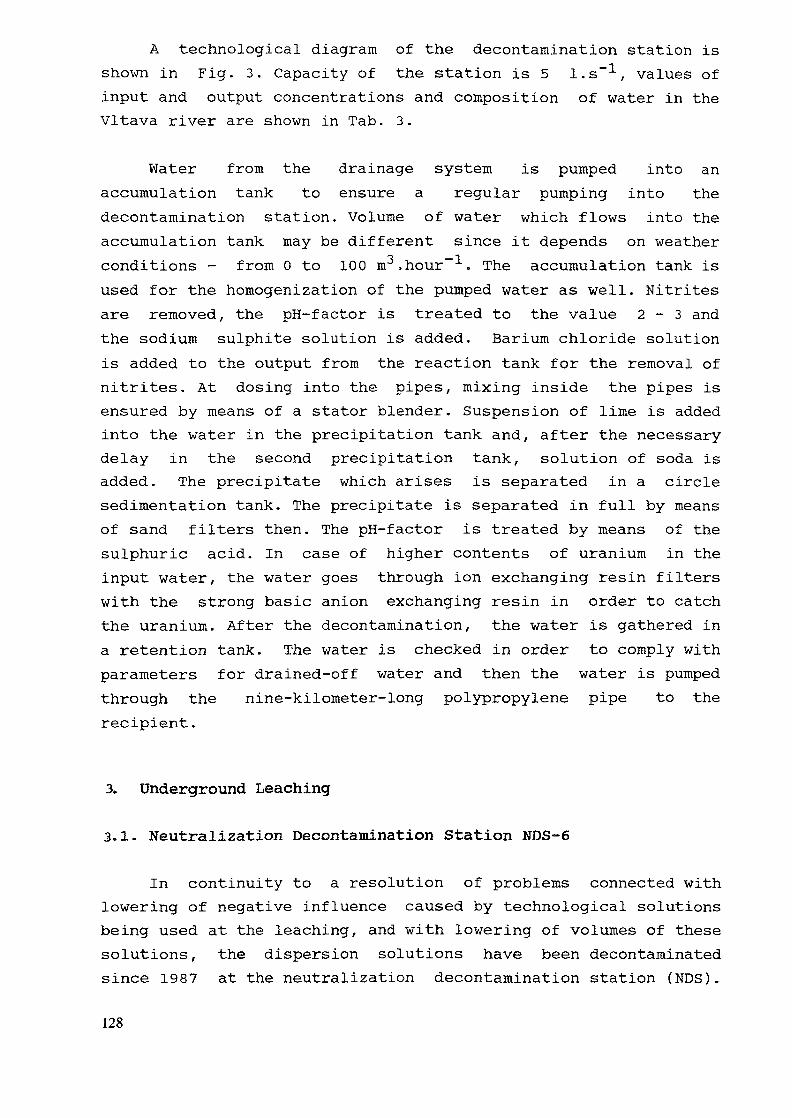
A technological diagram of the decontamination station isshown in Fig. 3. Capacity of the station is 5 l.s"1, values ofinput and output concentrations and composition of water in theVltava river are shown in Tab. 3.
Water from the drainage system is pumped into anaccumulation tank to ensure a regular pumping into thedecontamination station. Volume of water which flows into theaccumulation tank may be different since it depends on weatherconditions - from 0 to 100 m3.hour~1. The accumulation tank isused for the homogenization of the pumped water as well. Nitritesare removed, the pH-factor is treated to the value 2-3 andthe sodium sulphite solution is added. Barium chloride solutionis added to the output from the reaction tank for the removal ofnitrites. At dosing into the pipes, mixing inside the pipes isensured by means of a stator blender. Suspension of lime is addedinto the water in the precipitation tank and, after the necessarydelay in the second precipitation tank, solution of soda isadded. The precipitate which arises is separated in a circlesedimentation tank. The precipitate is separated in full by meansof sand filters then. The pH-f actor is treated by means of thesulphuric acid. In case of higher contents of uranium in theinput water, the water goes through ion exchanging resin filterswith the strong basic anion exchanging resin in order to catchthe uranium. After the decontamination, the water is gathered ina retention tank. The water is checked in order to comply withparameters for drained-off water and then the water is pumpedthrough the nine-kilometer-long polypropylene pipe to therecipient.
3. Underground Leaching
3.1. Neutralization Decontamination Station NDS-6
In continuity to a resolution of problems connected withlowering of negative influence caused by technological solutionsbeing used at the leaching, and with lowering of volumes of thesesolutions, the dispersion solutions have been decontaminatedsince 1987 at the neutralization decontamination station (NDS).
128
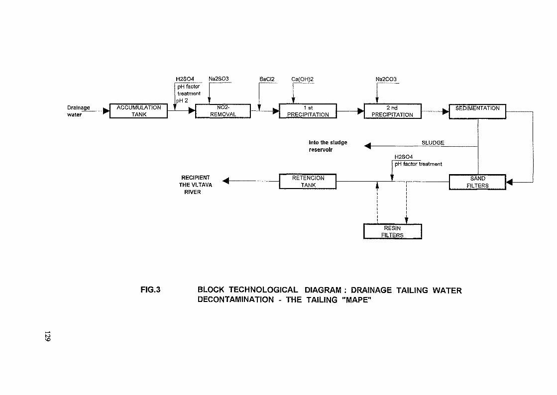
H2SO4 Na2SO3 BaCI2
waterage ^w ACCUMULATION
TANK
1
pH facttreatmepH2'
^_v^
ornt
\ i
NO2-REMOVAL
1th*p.
Ca(OH)2 Na2CO3
1 stPRECIPITATION
Into the sludgereservoir
RECIPIENTTHE VLTAVA
RIVER
RETENCIONTANK
2ndPRECIPITATION
SEDIMENTATION
SLUDGE
H2SO4pH factor treatment
SANDFILTERS
RESINFILTERS
FIG.3 BLOCK TECHNOLOGICAL DIAGRAM : DRAINAGE TAILING WATERDECONTAMINATION - THE TAILING "MAPE"
to
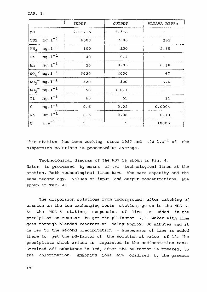
TAB. 3 :
pH
TDS mg.l"1
NH4 mg.l"1
Fe mg.l"1
Mn mg.l"1
S042~mg.l~1
NO3~ mg.l"1
NO2~ mg.l"1
Cl mg.l"1
U mg.l"1
Ra Bq.l"1
Q l.s"1
INPUT7.0-7.5
65001004026
3900
320
50
65
0.60.55
OUTPUT6.5-8
7600
100
0.4
0.05
4000320
< 0.1
650.020.08
5
VLTAVA RIVER-
282
2.89
-
0.18676.6-
250.0004
0.1310000
This station has been working since 1987 and 100 l.sdispersion solutions is processed on average.
-1 of the
Technological diagram of the NDS is shown in Fig. 4.Water is processed by means of two technological lines at thestation. Both technological lines have the same capacity and thesame technology. Values of input and output concentrations areshown in Tab. 4.
The dispersion solutions from underground, after catching ofuranium on the ion exchanging resin station, go on to the NDS-6.At the NDS-6 station, suspension of lime is added in theprecipitation reactor to get the pH-factor 7,5. Water with limegoes through blended reactors at delay approx. 30 minutes and itis led to the second precipitation - suspension of lime is addedthere to get the pH-f actor of the solution at value of 12. Theprecipitate which arises is separated in the sedimentation tank.Strained-off substance is led, after the pH-factor is treated, tothe chlorination. Ammonium ions are oxidized by the gaseous
130
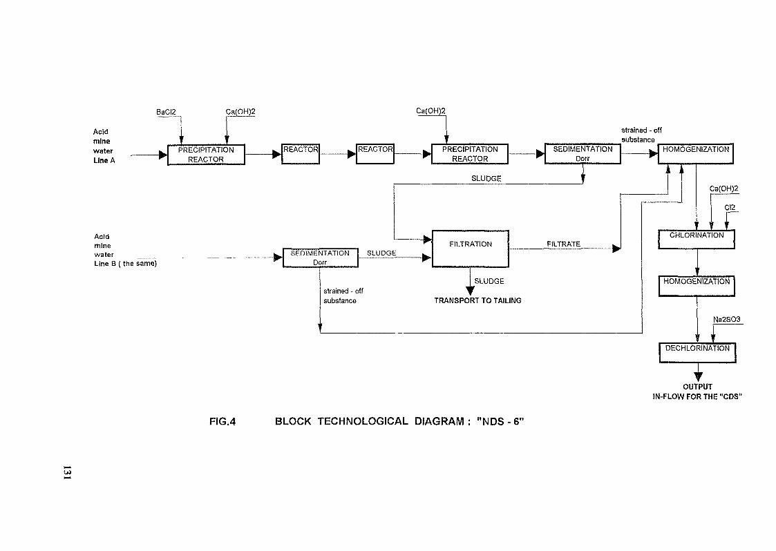
BaCI2 Ca(OH)2 Ca(OH)2
AcidminewaterLine A
—— »,1 ,1
PRECIPITATIONREACTOR
———— REACTOR———— >
REACTOR
\
———~ >
i
PRECIPITATIONREACTOR
Acidminewater _____Line B (the same)
SEDIMENTATIONDorr
SLUDGE
strained - offsubstance
SLUDGE
FILTRATION
I SLUDGE
TRANSPORT TO TAILING
strained - offsubstance
SEDIMENTATIONDorr
FILTRATE
HOMOGENIZATiON
Ca(OH)2
CI2
CHLORINATION
HOMOGENIZATION
Na2SO3
DECHLORINATION
OUTPUTIN-FLOW FOR THE "CDS"
FIG.4 BLOCK TECHNOLOGICAL DIAGRAM : "NDS - 6"
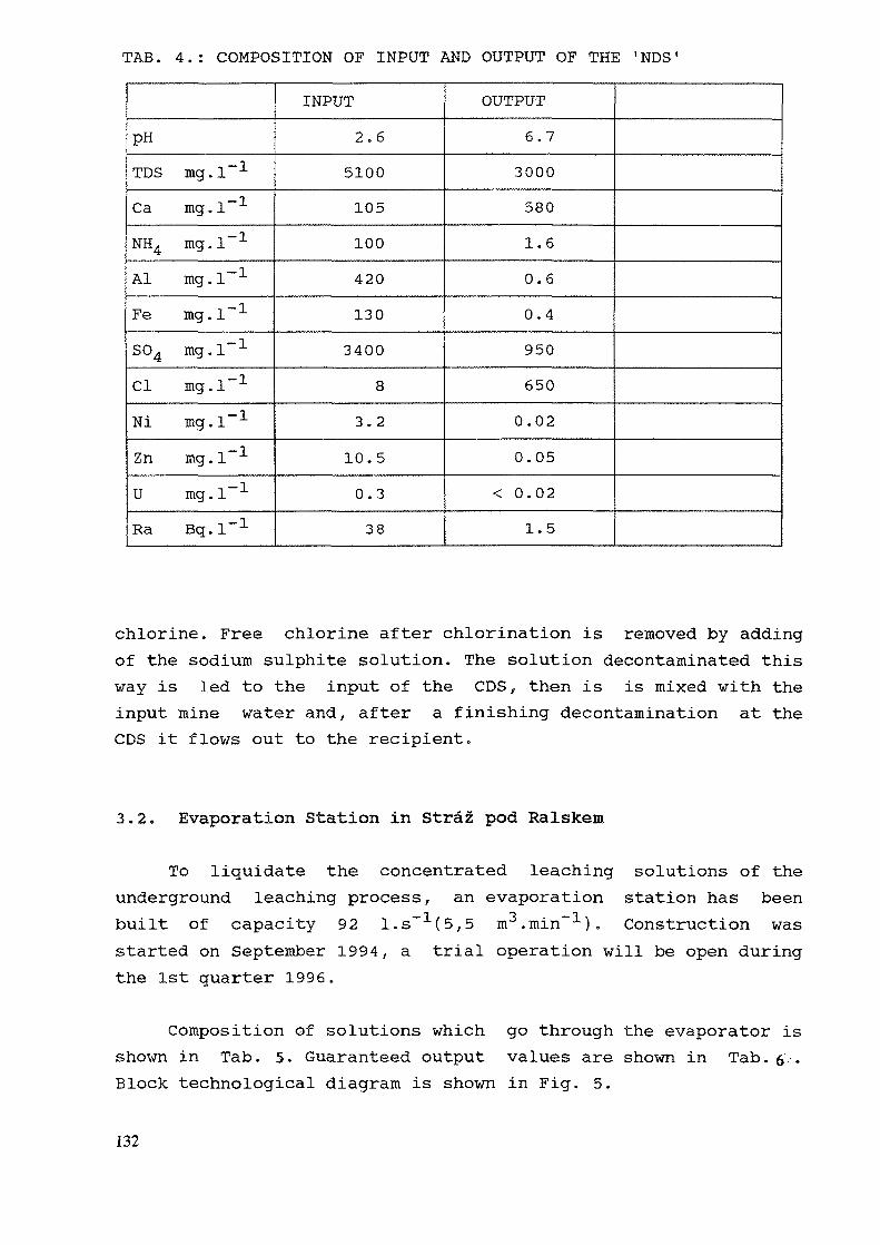
TAB. 4.: COMPOSITION OF INPUT AND OUTPUT OF THE 'NDS1
PHTDS mg.l"1
Ca mg.l"1
NH4 mg.l"1
Al mg.l"1
Fe mg.l"1
S04 mg.l"1
Cl mg.l"1
Ni mg.l"1
Zn mg.l"1
U mg.l"1
Ra Bq.l"1
INPUT2.6
5100105100420
130
34008
3,2
10.50.3
38
OUTPUT6.73000
580
1.60.6
0.4950
650
0.02
0.05
< 0.021.5
chlorine. Free chlorine after chlorination is removed by addingof the sodium sulphite solution. The solution decontaminated thisway is led to the input of the CDS, then is is mixed with theinput mine water and, after a finishing decontamination at theCDS it flows out to the recipient.
3.2. Evaporation Station in Straz pod Ralskem
To liquidate the concentrated leaching solutions of theunderground leaching process, an evaporation station has beenbuilt of capacity 92 l.s~1(5,5 m3.min~1). Construction wasstarted on September 1994, a trial operation will be open duringthe 1st quarter 1996.
Composition of solutions which go through the evaporator isshown in Tab. 5. Guaranteed output values are shown in Tab. 6 .Block technological diagram is shown in Fig. 5.
132
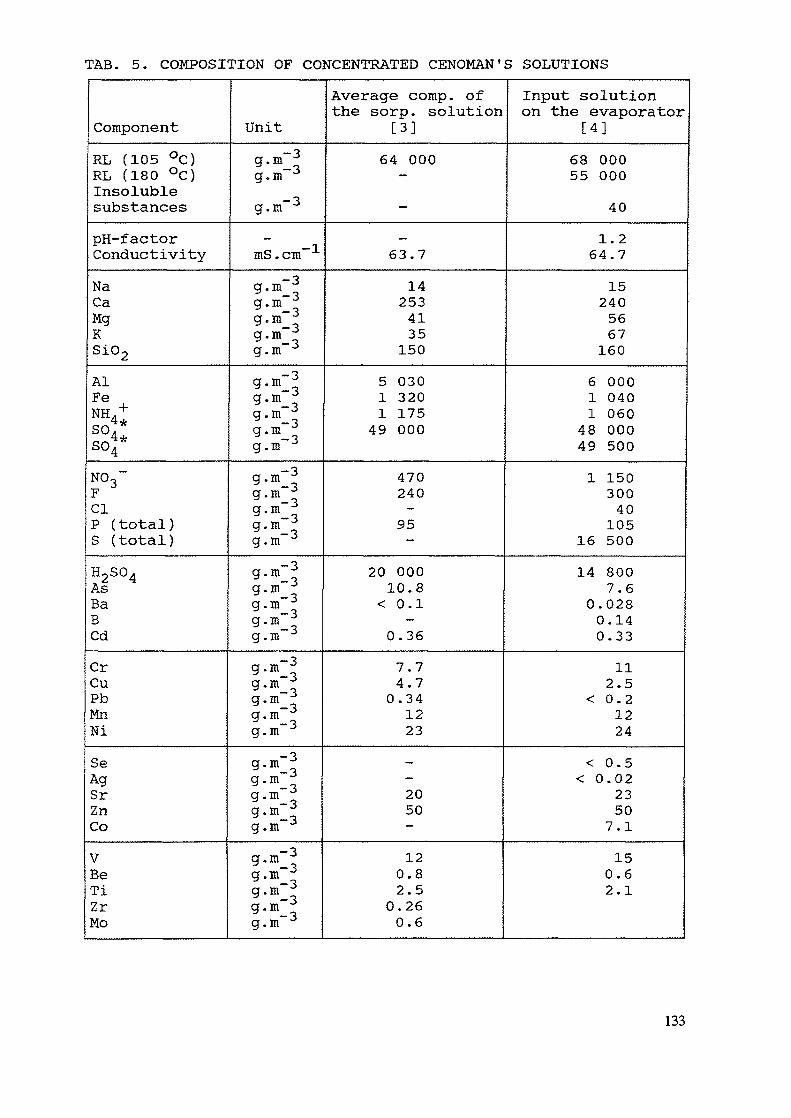
TAB. 5. COMPOSITION OF CONCENTRATED CENOMAN'S SOLUTIONS
ComponentRL (105 °C)RL (180 °C)InsolublesubstancespH-factorConductivityNaCaMgKSi02AlFeNH +qn4*so4*N03~FClP (total)S (total)H2S04AsBaBCdCrCuPbMnNiSeAgSrZnCoVBeTiZrMo
Unitg.mg.mg.m"3_mS.cm
-3a m~3* —3am"3
g.m"g.m~3am"3
g.m"3g.mg.mg.m"3g.mg.m~3g.mg.m"g-rc"3g-ra tg.mg.m"3g.m"g.m~3— 39'm_og.m-3g.mg.m"3
g.m"3g.m"3g.mfT TT>~3
g.mg.m"3g.m"-3
" —3g.m"3
Average comp. ofthe sorp. solution
[3]64 000--_63.7
142534135150
5 0301 3201 17549 000
470240-95-
20 00010.8
< 0.1-
0.36
7.74.70.341223_-2050—
120.82.50.260.6
Input solutionon the evaporator
[4]68 00055 000
40
1.264.71524056671606 0001 0401 06048 00049 5001 15030040105
16 50014 800
7.60.0280.140.33
112.5
< 0.21224
< 0.5< 0.02
23507.1150.62.1
133
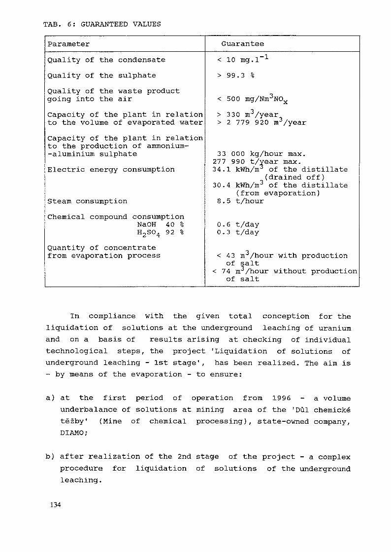
TAB. 6: GUARANTEED VALUES
Parameter GuaranteeQuality of the condensateQuality of the sulphateQuality of the waste productgoing into the airCapacity of the plant in relationto the volume of evaporated waterCapacity of the plant in relationto the production of ammonium--aluminium sulphateElectric energy consumption
Steam consumptionChemical compound consumption
NaOH 40 %H2S04 92 %
Quantity of concentratefrom evaporation process
< 10 mg.l> 99.3 %
•— 1
< 500 mg/Nm3NOvA.> 330 m3/year> 2 779 920 m3/year
33 000 kg/hour max.277 990 t/vear max.34.1 kWh/m3 of the distillate
(drained off)30.4 kWh/m3 of the distillate
(from evaporation)8.5 t/hour
0.6 t/day0.3 t/day
< 43 m /hour with productionof salt
< 74 m3/hour without productionof salt
In compliance with the given total conception for theliquidation of solutions at the underground leaching of uraniumand on a basis of results arising at checking of individualtechnological steps, the project 'Liquidation of solutions ofunderground leaching - 1st stage', has been realized. The aim is- by means of the evaporation - to ensure:
a) at the first period of operation from 1996 - a volumeunderbalance of solutions at mining area of the 'Dul chemicketezby* (Mine of chemical processing), state-owned company,DIAMO;
b) after realization of the 2nd stage of the project - a complexprocedure for liquidation of solutions of the undergroundleaching.
134
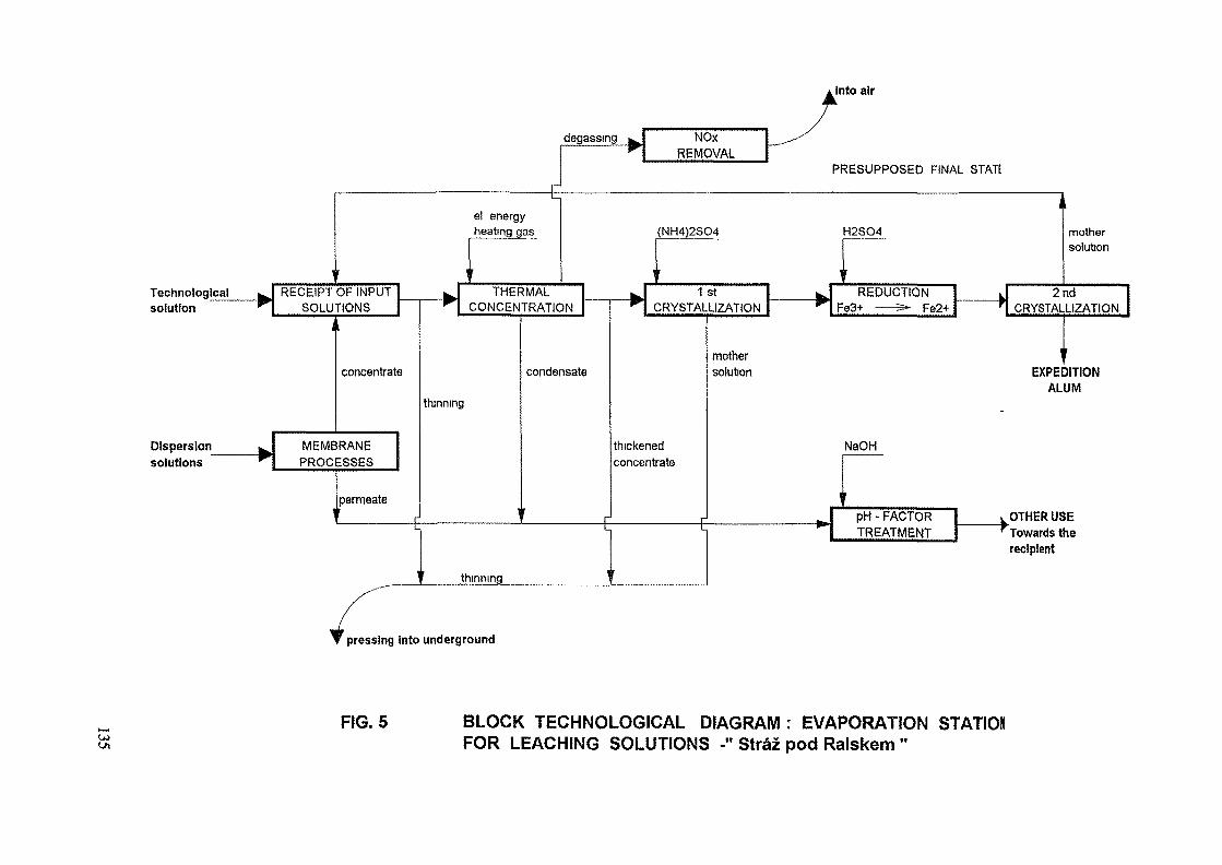
, Into air
Technologicalsolution
Dispersionsolutions
degassing w NOxREMOVAL
PRESUPPOSED FINAL STATE
leal ^~
^^
] '
RECEIPT OF INPUTSOLUTIONS
I ,
*.
concentrate
MEMBRANEPROCESSES
ipermeate
— E
i
w
1
.... —
el energyheating gas
'
THERMALCONCENTRATION
thinning
.
condensate
thinning
— E:
i
ri
1 1
(NH4)2SO4 H2SO4 mothersolution
' 11 st ^ REDUCTION k 2 nd
CRYSTALLIZATION ^ Fe3-»- —— 5- Fe2+ r CRYSTALLIZATION
thickenedconcentrate
——— E
mother ysolution EXPEDITION
ALUM
-
NaOH
i •
pH - FACTOR i OTHER USETREATMENT ^Towards the
recipient
pressing into underground
FIG. 5 BLOCK TECHNOLOGICAL DIAGRAM : EVAPORATION STATIOXFOR LEACHING SOLUTIONS -" Straz pod Ralskem "
The first stage includes all technological plant to ensurethe following technological steps:
* Concentrated solutions of the underground leaching of uraniumare pumped from the place of rise. They are concentrated ina membrane process unit and the concentrate is gathered inreception tanks. Joined concentrates are pumped to a thermalconcentration unit.
* The solution is concentrated in the thermal concentration unitso that conditions for crystallization of a solid portion fromthe thickened concentrate after cooling are created.The distillate is treated (neutralized) to the values whichenable to drain it off to the recipient. The concentrate goeson to the crystallization of salts.
* After cooling, a crystalline portion is separated from theconcentrated solution, which consists mainly of ammonium- aluminium sulphate. In case of need, an ammonium anion in theform of ammonium sulphate is added in the place of thecrystallization. Mother solution from the crystallization ispumped into expedition tanks. The separated crystalline portionis led to a re-crystallization.
* The crystalline portion is dissolved and, after cooling, it isseparated again and goes through a washing process. Mothersolutions are pumped into expedition tanks, or, if need be,they are recycled to the input of the thermal concentrationunit. Recrystalled ammonium-aluminium sulphate is dewatered andtaken away of the system for another use.
* The solution which consists of waste solutions after thecrystallization, recrystallization an, if need be, after thewashing of crystals, is gathered in expedition tanks and, afterthinning by the origin solution is pumped to the place ofconsumption.
The technological plant enables - in compliance with thetwo-level conception for the realization of technology for theliquidation of solutions - an operation in two basic regimes:
136
Regime I : includes the technological procedure explained abovein full extent
Regime II : The crystallization unit and the recrystallizationunit are not in operation in this regime. Theconcentrate from the thermal concentration unit goeson to the expedition unit directly. This way, theplant will be used till the time of realization ofthe technical plants belonging to the 2nd stage ofthe project.
Both regimes may be operated either with use of a membraneprocess unit or without this unit. Interconnection among allthese three operational sets enables an operation in fourvariants:
1. Regime I including the membrane processes (the complexoperation)
2. Regime I without the membrane processes3. Regime II including the membrane processes4. Regime II without the membrane processes (minimum)
Authors of this contribution have been the main designers ofthe decontamination technology for the central decontaminationstation, for the neutralization decontamination station and forthe drainage water decontamination station MAPE.
137
REMEDIATION OF ECARPIERE URANIUMTAILING POND BY COGEMA (FRANCE)
Ph. CROCHON, J.L. DAROUSSINCOGEMA,France
Abstract
Division of Vendee has been operated by COGEMA from 1954 to 1991. The main site is namedECARPIERE where underground and open pit mining fed a mill and heap leaching facilities which produced alltogether 150001 of Uranium.The frame of the methodology was presented during the second workshop in Piestany [1]. Specific informations anddetails concerning inventory of ECARPIERE, the materials used on this site, results of the studies are given.Main points for implementation are mill dismantling, resloping of the dykes, covering of the impoundment andwater management. Every step needs a careful radiological and topographical follow up.Post remediation monitoring is adapted from the initial network to the new situation of the site.
I - HISTORICAL BACKGROUND
ECARPIERE, located at Getigne (Loire Atlantique - France) on the border of river Moine has been one of the threemain uranium extraction site of COGEMA's mining division of Vendee.
Prospection started in 1950 allowing underground mining to begin in 1953 : maximum extension was 3 kilometerslong and 500m deep producing 3600 tU.Three open pit (maximum depth 50m - total production 475 tU) mark out the upper part of the mineralised structure.
Ore treatment developed in two stages :
- from 1957 to 1991 a mill (acid pulp leaching - maximum capacity 450000 t/year) treated 9000 kt containing14000tU,- in 1967 heap leaching pads have been built for poor ore (grade <600ppm - 4000 kt) producing 6 millionscubic meter of uranium bearing solutions containing more than 1200 tU,- total output has been 14761 tU.
Remediation of the mill facilities is the chalenge for this site. The frame for the operations described hereafter is setin the updated operating license issued on May 16th 1983 :
- drying of the pond,- covering and reshaping of the site,- seeding,- monitoring,
The general principles and the main objectives have been listed in the previous presentation [1].Remediation started hi 1992 and should be completed next year.
II - CHARACTERISTICS OF THE SITE AND THE PRODUCTS
Total area is 240 ha divided in units (see Figure 1) which characteristics are different and need specific management.
II.1.1 - Open pits
Remediation of these areas - partial backfilling, mining debries damps recountering, revegetation - does not leaveany material left on site.
139
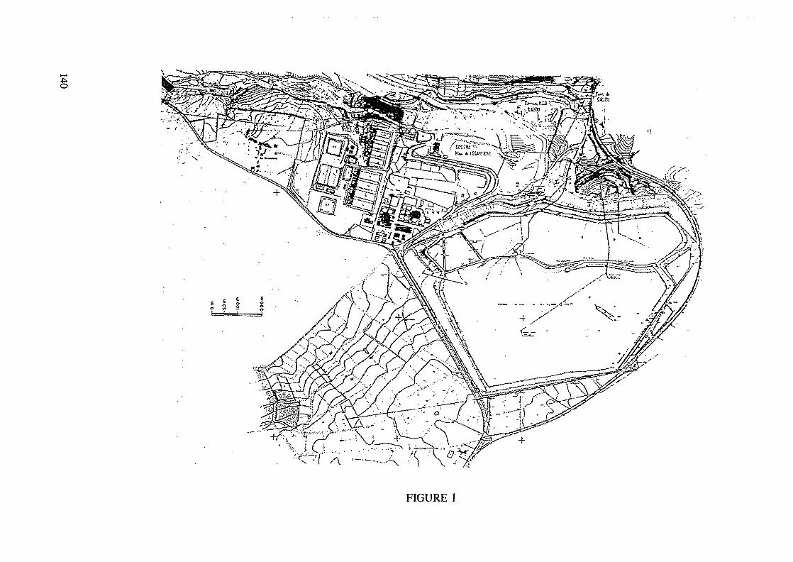
FIGURE 1
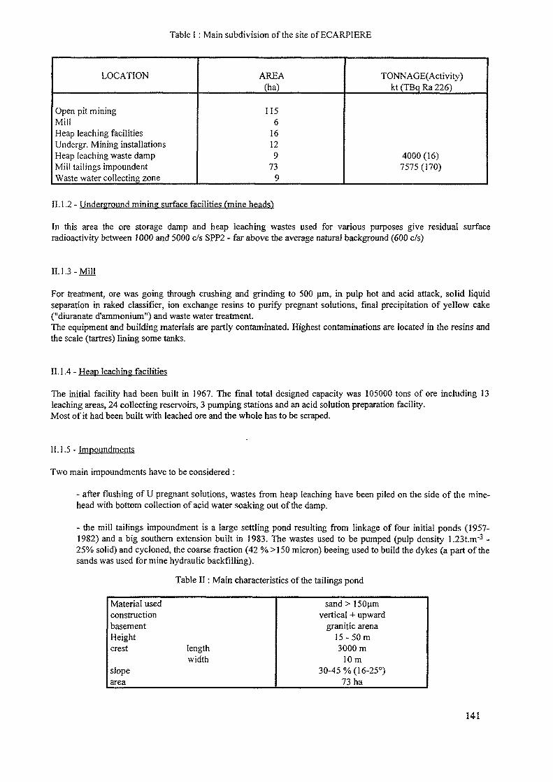
Table I : Main subdivision of the site of ECARPIERE
LOCATION
Open pit miningMillHeap leaching facilitiesUndergr. Mining installationsHeap leaching waste dampMill tailings impoundentWaste water collecting zone
AREA(ha)
1156
16129
739
TONNAGE(Activity)kt(TBqRa226)
4000(16)7575 (170)
II. 1.2 - Underground mining surface facilities (mine heads)
In this area the ore storage damp and heap leaching wastes used for various purposes give residual surfaceradioactivity between 1000 and 5000 c/s SPP2 - far above the average natural background (600 c/s)
II. 1.3-Mill
For treatment, ore was going through crushing and grinding to 500 urn, in pulp hot and acid attack, solid liquidseparation in raked classifier, ion exchange resins to purify pregnant solutions, final precipitation of yellow cake("diuranate d'ammonium") and waste water treatment.The equipment and building materials are partly contaminated. Highest contaminations are located in the resins andthe scale (tartres) lining some tanks.
II. 1.4 - Heap leaching facilities
The initial facility had been built in 1967. The final total designed capacity was 105000 tons of ore including 13leaching areas, 24 collecting reservoirs, 3 pumping stations and an acid solution preparation facility.Most of it had been built with leached ore and the whole has to be scraped.
II. 1.5 - Impoundments
Two main impoundments have to be considered :
- after flushing of U pregnant solutions, wastes from heap leaching have been piled on the side of the mine-head with bottom collection of acid water soaking out of the damp.
- the mill tailings impoundment is a large settling pond resulting from linkage of four initial ponds (1957-1982) and a big southern extension built in 1983. The wastes used to be pumped (pulp density 1.23t.m"3 -25% solid) and cycloned, the coarse fraction (42 % >150 micron) beeing used to build the dykes (a part of thesands was used for mine hydraulic backfilling).
Table II: Main characteristics of the tailings pond
Material usedconstructionbasementHeightcrest length
widthslopearea
sand > 1 50umvertical + upward
granitic arena15 -50m3000m
10m30-45% (16-25°)
73 ha
141
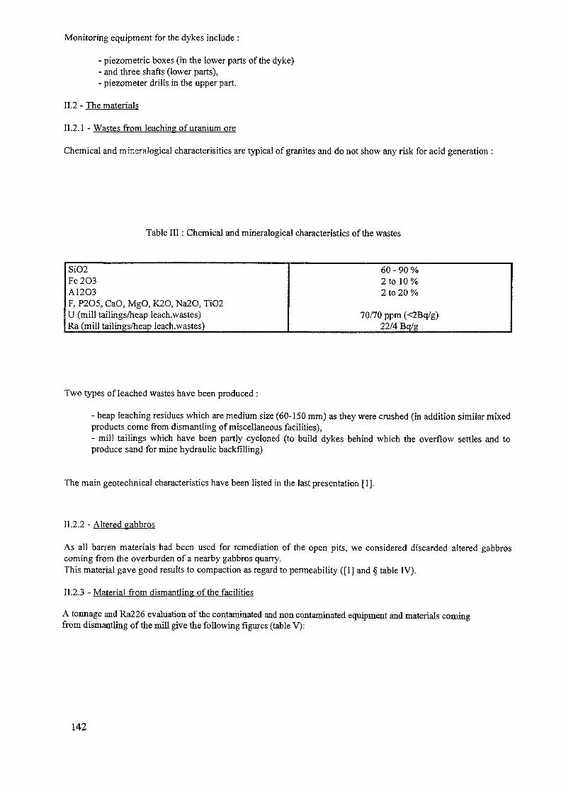
Monitoring equipment for the dykes include :
- piezometric boxes (in the lower parts of the dyke)- and three shafts (lower parts),- piezometer drills in the upper part.
11.2 - The materials
II.2.1 - Wastes from leaching of uranium ore
Chemical and mineralogical characteristics are typical of granites and do not show any risk for acid generation :
Table III: Chemical and mineralogical characteristics of the wastes
SiO2Fe2O3A12O3F, P205, CaO, MgO, K2O, Na2O, TiO2U (mill tailings/heap leach.wastes)Ra (mill tailings/heap leach.wastes)
60 - 90 %2 to 10%2 to 20 %
70/70 ppm (<2Bq/g)22/4 Bq/g
Two types of leached wastes have been produced :
- heap leaching residues which are medium size (60-150 mm) as they were crushed (in addition similar mixedproducts come from dismantling of miscellaneous facilities),- mill tailings which have been partly cycloned (to buiid dykes behind which the overflow settles and toproduce sand for mine hydraulic backfilling)
The main geotechnical characteristics have been listed in the last presentation [1].
11.2.2 - Altered gabbros
As all barren materials had been used for remediation of the open pits, we considered discarded altered gabbroscoming from the overburden of a nearby gabbros quarry.This material gave good results to compaction as regard to permeability ([1] and § table IV).
11.2.3 - Material from dismantling of the facilities
A tonnage and Ra226 evaluation of the contaminated and non contaminated equipment and materials comingfrom dismantling of the mill give the following figures (table V):
142
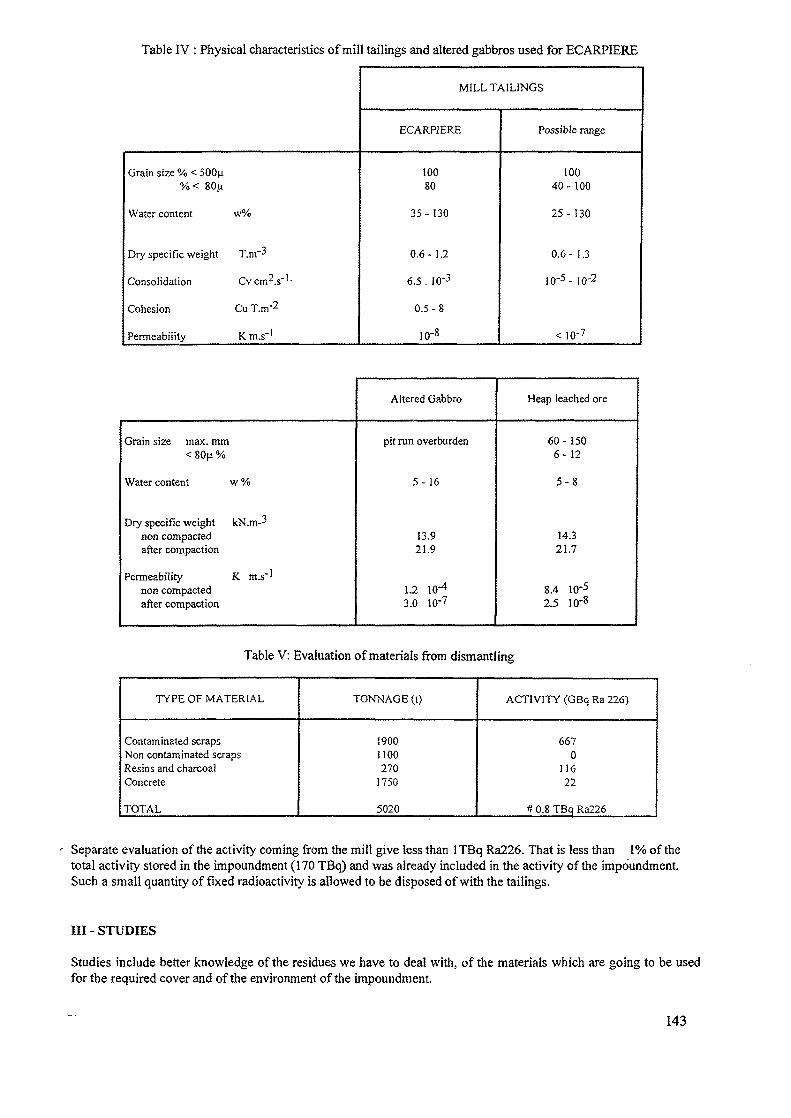
Table IV : Physical characteristics of mill tailings and altered gabbros used for ECARPIERE
MILL TAILINGS
ECARPIERE Possible range
Grain size % < 500^
Water content w%
Dry specific weight T.m'-'
Consolidation Cv cm2.s"' •
Cohesion Cu T.m~2
Permeability Km.s"1
10080
35-130
0.6-1.2
6.5 . !0'3
0.5-8
io-8
10040- 100
25-130
0.6- 1.3
IO-5- iO-2
< 10'7
Grain size max. mm< 80|i %
Water content w %
Dry specific weight kN.m-3non compactedafter compaction
Permeability K m.s"1
non compactedafter compaction
Altered Gabbro
pit run overburden
5-16
13.921.9
1.2 10"4
3.0 10'7
Heap leached ore
60-1506-12
5 -8
14.321.7
8.4 10'52.5 10'8
Table V: Evaluation of materials from dismantling
TYPE OF MATERIAL
Contaminated scrapsNon contaminated scrapsResins and charcoalConcrete
TOTAL
TONNAGE (t)
!900HOO270
1750
5020
ACTIVITY (GBq Ra 226)
6670
11622
ft 0.8 TBc^ Ra226
Separate evaluation of the activity coming from the mill give less than ITBq Ra226. That is less than 1% of thetotal activity stored in the impoundment (170 TBq) and was already included in the activity of the impoundment.Such a small quantity of fixed radioactivity is allowed to be disposed of with the tailings.
Ill - STUDIES
Studies include better knowledge of the residues we have to deal with, of the materials which are going to be usedfor the required cover and of the environment of the impoundment.
143
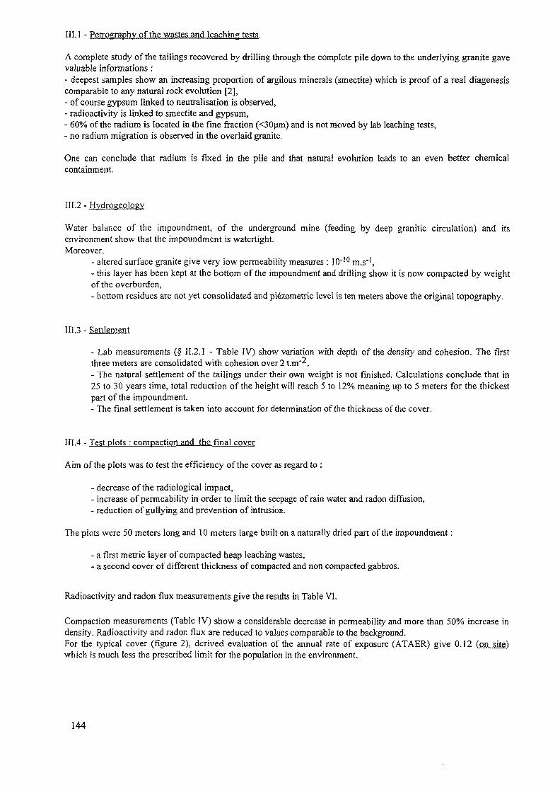
III. 1 - Petrography of the wastes and leaching tests.
A complete study of the tailings recovered by drilling through the complete pile down to the underlying granite gavevaluable informations :- deepest samples show an increasing proportion of argilous minerals (smectite) which is proof of a real diagenesiscomparable to any natural rock evolution [2],- of course gypsum linked to neutralisation is observed,- radioactivity is linked to smectite and gypsum,- 60% of the radium is located in the fine fraction (<30um) and is not moved by lab leaching tests,- no radium migration is observed in the overlaid granite.
One can conclude that radium is fixed in the pile and that natural evolution leads to an even better chemicalcontainment.
II1.2 - Hydrogeology
Water balance of the impoundment, of the underground mine (feeding by deep granitic circulation) and itsenvironment show that the impoundment is watertight.Moreover,
- altered surface granite give very low permeability measures : 10"!0 m.s'1,- this layer has been kept at the bottom of the impoundment and drilling show it is now compacted by weightof the overburden,- bottom residues are not yet consolidated and piezometric level is ten meters above the original topography.
III.3 - Settlement
- Lab measurements (§ 11.2.1 - Table IV) show variation with depth of the density and cohesion. The firstthree meters are consolidated with cohesion over 2 t.m~2.- The natural settlement of the tailings under their own weight is not finished. Calculations conclude that in25 to 30 years time, total reduction of the height will reach 5 to 12% meaning up to 5 meters for the thickestpart of the impoundment.- The final settlement is taken into account for determination of the thickness of the cover.
II1.4 - Test plots : compaction and the final cover
Aim of the plots was to test the efficiency of the cover as regard to :
- decrease of the radiological impact,- increase of permeability in order to limit the seepage of rain water and radon diffusion,- reduction of gullying and prevention of intrusion.
The plots were 50 meters long and 10 meters large built on a naturally dried part of the impoundment:
- a first metric layer of compacted heap leaching wastes,- a second cover of different thickness of compacted and non compacted gabbros.
Radioactivity and radon flux measurements give the results in Table VI.
Compaction measurements (Table IV) show a considerable decrease in permeability and more than 50% increase indensity. Radioactivity and radon flux are reduced to values comparable to the background.For the typical cover (figure 2), derived evaluation of the annual rate of exposure (ATAER) give 0.12 (on site)which is much less the prescribed limit for the population in the environment.
144
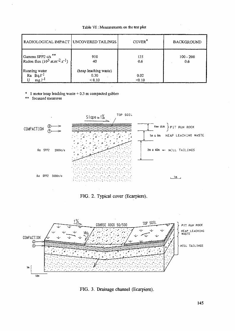
Table VI: Measurements on the test plot
RADIOLOGICAL IMPACT
Gamma SPP2 c/s **Radon flux (105 at.m^.s'1)
Running waterRa Bq.r1
U mg.l"1
UNCOVERED TAILINGS
91040
(heap leaching waste)0.30
<0.10
COVER*
1350.6
0.02<O.IO
BACKGROUND
100-2000.6
* 1 meter heap leaching waste + 0.3 m compacted gabbro** focussed measures
Slope»1% TOP SOIL
COMPACTION
Ro SPP2 20000/s
few dcm t PIT RUN ROCK
1m a 8m HEAP LEACHING WASTE
2m a 40m «- M I L L T A I L I N G S
Ra SPP2 SOOOc/s
FIG. 2. Typical cover (Ecarpiere).
COMPACTION
10m
FIG. 3. Drainage channel (Ecarpiere).
1m
PIT RUN ROCKHEAP LEACHINGWASTE
MILL TAILINGS
145
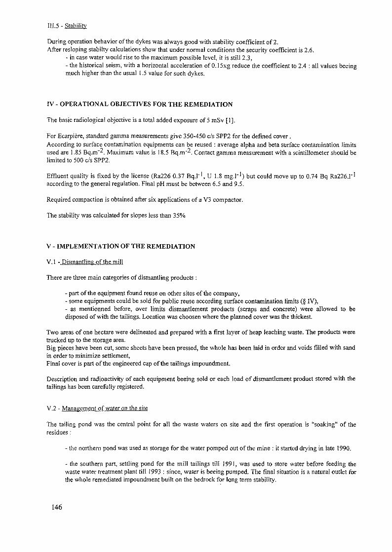
During operation behavior of the dykes was always good with stability coefficient of 2.After resloping stabilty calculations show that under normal conditions the security coefficient is 2.6.
- in case water would rise to the maximum possible level, it is still 2.3,- the historical seism, with a horizontal acceleration of O.lSxg reduce the coefficient to 2.4 : all values beeingmuch higher than the usual 1.5 value for such dykes.
IV - OPERATIONAL OBJECTIVES FOR THE REMEDIATION
The basic radiological objective is a total added exposure of 5 mSv [1].
For Ecarpiere, standard gamma measurements give 350-450 c/s SPP2 for the defined cover.According to surface contamination equipments can be reused : average alpha and beta surface contamination limitsused are 1.85 Bq.m"2. Maximum value is 18.5 Bq.m'2. Contact gamma measurement with a scintillometer should belimited to 500 c/s SPP2.
Effluent quality is fixed by the license (Ra226 0.37 Bq.l"1, U 1.8 mg.1"1) but could move up to 0.74 Bq Ra226.1"1
according to the general regulation. Final pH must be between 6.5 and 9.5.
Required compaction is obtained after six applications of a V3 compactor.
The stability was calculated for slopes less than 35%
V - IMPLEMENTATION OF THE REMEDIATION
V.I - Dismantling of the mill
There are three main categories of dismantling products :
- part of the equipment found reuse on other sites of the company,- some equipments could be sold for public reuse according surface contamination limits (§ IV),- as mentionned before, over limits dismantlement products (scraps and concrete) were allowed to bedisposed of with the tailings. Location was choosen where the planned cover was the thickest.
Two areas of one hectare were delineated and prepared with a first layer of heap leaching waste. The products weretrucked up to the storage area.Big pieces have been cut, some sheets have been pressed, the whole has been laid in order and voids filled with sandin order to minimize settlement,Final cover is part of the engineered cap of the tailings impoundment.
Description and radioactivity of each equipment beeing sold or each load of dismantlement product stored with thetailings has been carefully registered.
V.2 - Management of water on the site
The tailing pond was the central point for all the waste waters on site and the first operation is "soaking" of theresidues:
- the northern pond was used as storage for the water pomped out of the mine : it started drying in late 1990.
- the southern pan, settling pond for the mill tailings till 1991, was used to store water before feeding thewaste water treatment plant till 1993 : since, water is beeing pumped. The final situation is a natural outlet forthe whole remediated impoundment built on the bedrock for long term stability.
146
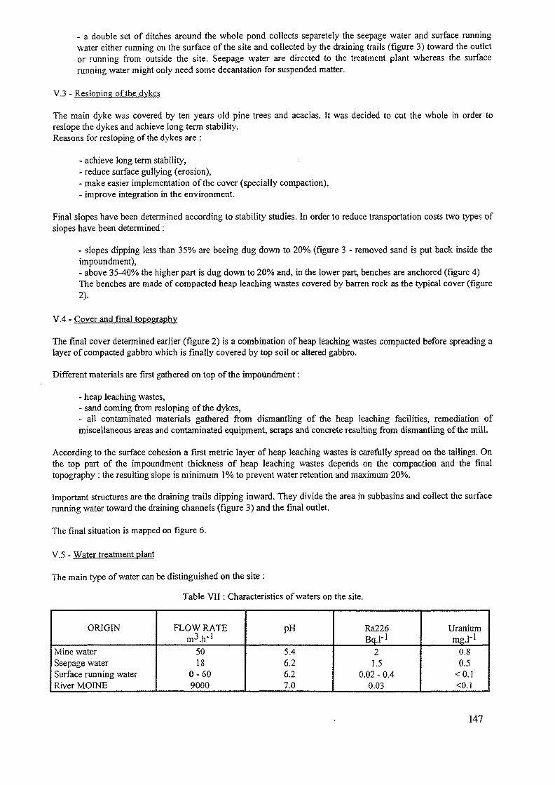
- a double set of ditches around the whole pond collects separetely the seepage water and surface runningwater either running on the surface of the site and collected by the draining trails (figure 3) toward the outletor running from outside the site. Seepage water are directed to the treatment plant whereas the surfacerunning water might only need some decantation for suspended matter.
V.3 - Resloping of the dykes
The main dyke was covered by ten years old pine trees and acacias. It was decided to cut the whole in order toreslope the dykes and achieve long term stability.Reasons for resloping of the dykes are :
- achieve long term stability,- reduce surface gullying (erosion),- make easier implementation of the cover (specially compaction),- improve integration in the environment.
Final slopes have been determined according to stability studies. In order to reduce transportation costs two types ofslopes have been determined :
- slopes dipping less than 35% are beeing dug down to 20% (figure 3 - removed sand is put back inside theimpoundment),- above 35-40% the higher part is dug down to 20% and, in the lower part, benches are anchored (figure 4)The benches are made of compacted heap leaching wastes covered by barren rock as the typical cover (figure2).
V.4 - Cover and final topography
The final cover determined earlier (figure 2) is a combination of heap leaching wastes compacted before spreading alayer of compacted gabbro which is finally covered by top soil or altered gabbro.
Different materials are first gathered on top of the impoundment:
- heap leaching wastes,- sand coming from resloping of the dykes,- all contaminated materials gathered from dismantling of the heap leaching facilities, remediation ofmiscellaneous areas and contaminated equipment, scraps and concrete resulting from dismantling of the mill.
According to the surface cohesion a first metric layer of heap leaching wastes is carefully spread on the tailings. Onthe top part of the impoundment thickness of heap leaching wastes depends on the compaction and the finaltopography : the resulting slope is minimum 1 % to prevent water retention and maximum 20%.
Important structures are the draining trails dipping inward. They divide the area in subbasins and collect the surfacerunning water toward the draining channels (figure 3) and the final outlet.
The final situation is mapped on figure 6.
V.5 - Water treatment plant
The main type of water can be distinguished on the site :
Table VII: Characteristics of waters on the site.
ORIGIN
Mine waterSeepage waterSurface running waterRiver MOINE
FLOW RATEm3.}!'1
5018
0-609000
PH
5.46.26.27.0
Ra226Bq.H
21.5
0.02 - 0.40.03
Uraniummg.r1
0.80.5
<0.1<0.1
147
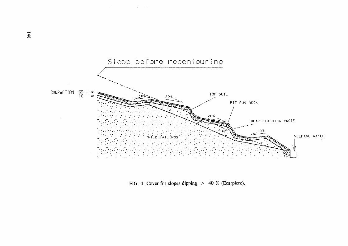
oo
COMPACTION
Slope before recontouring
TOP SOILPIT RUN ROCK
HEAP LEACHING WASTE
107.SEEPAGE WATER
FIG. 4. Cover for slopes dipping > 40 % (Ecarpiere).
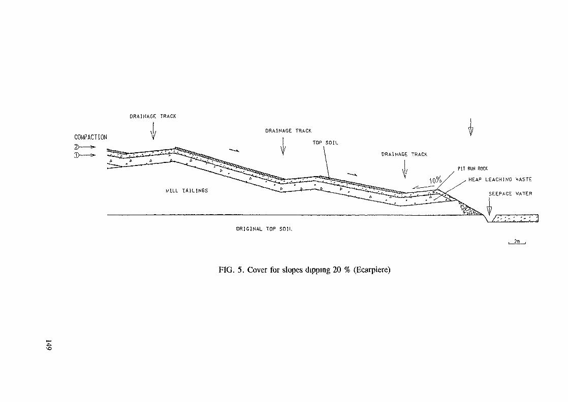
DRAINAGE TRACK
COMPACTIONDRAINAGE TRACK
TOP SOILDRAINAGE TRACK
PIT RUM ROCKHEAP LEACHING V.ASTE
SEEPAGE WATER
ORIGINAL TOP SOIL
FIG. 5. Cover for slopes dipping 20 % (Ecarpiere)
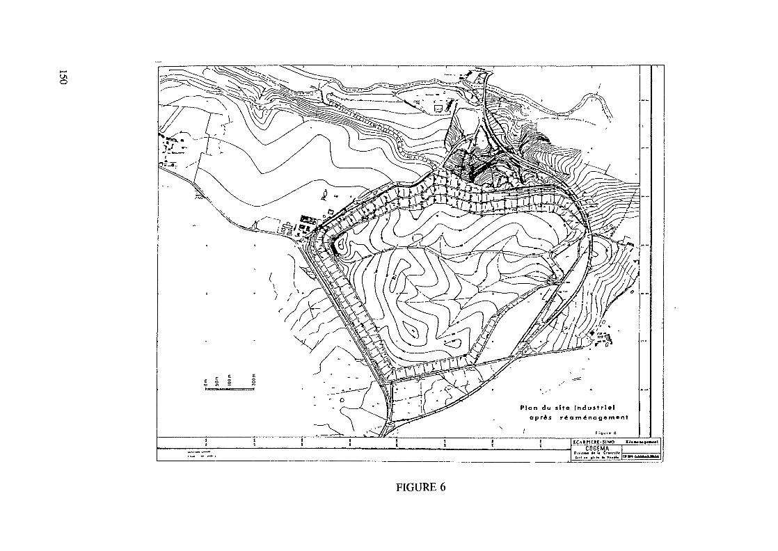
Plan du slto Industrie!
FIGURE 6
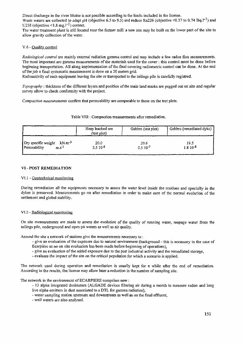
Direct discharge in the river Moine is not possible according to the limits included in the license.Waste waters are collected to adapt pH (objective 6.5 to 9.5) and reduce Ra226 (objective <0.37 to 0.74 Bq.H) andU238 (objective <1.8 mg.H) content.The water treatment plant is still located near the former mill: a new one may be built on the lower part of the site toallow gravity collection of the water.
V.6 - Quality control
Radiological control are mainly external radiation gamma control and may include a few radon flux measurements.The most important are gamma measurements of the materials used for the cover : this control must be done beforebeginning transportation. All along implementation of the final covering radiometric control can be done. At the endof the job a final systematic measurement is done on a 20 meters grid.Radioactivity of each equipment leaving the site or transported to the tailings pile is carefully registred.
Topography : thickness of the different layers and position of the main land marks are pegged out on site and regularsurvey allow to check conformity with the project.
Compaction measurements confirm that permeability are comparable to those on the test plots.
Table VIII: Compaction measurements after remediation.
Dry specific weight kN.nr3
Permeability m.s~!
Heap leached ore(test plot)
20.03.5 ID'8
Gabbro (test plot)
20.60.5 lO'7
Gabbro (remediated dyke)
19.51.8 10-*
VI - POST REMEDIATION
VI. 1 - Geotechnical monitoring
During remediation all the equipments necessary to assess the water level inside the residues and specially in thedykes is preserved. Measurements go on after remediation in order to make sure of the normal evolution of thesettlement and global stability.
VI.2 - Radiological monitoring
On site measurements are made to assess the evolution of the quality of running water, seepage water from thetailings pile, underground and open pit waters as well as air quality.
Around the site a network of stations give the measurements necessary to :- give an evaluation of the exposure due to natural environment (background - this is necassary in the case ofEcarpiere as no on site evaluation has been made before beginning of operations),- give an evaluation of the added exposure due to the past industrial activity and the remediated storage,- evaluate the impact of the site on the critical population for which a scenario is applied.
The network used during operation and remediation is usually kept for a while after the end of remediation.According to the results, the license may allow later a reduction in the number of sampling site.
The network in the environment of ECARPIERE comprises now:- 13 alpha integrated dosimeters (ALGADE devices filtering air during a month to measure radon and longlive alpha emitters in dust associated to a DTL for gamma radiation),- water sampling station upstream and downstream as well as on the final effluent,- well waters are also analysed.
151
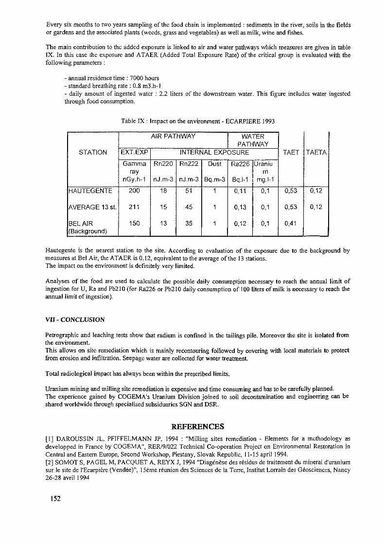
Every six months to two years sampling of the food chain is implemented : sediments in the river, soils in the fieldsor gardens and the associated plants (weeds, grass and vegetables) as well as milk, wine and fishes.
The main contribution to the added exposure is linked to air and water pathways which measures are given in tableIX. In this case the exposure and ATAER (Added Total Exposure Rate) of the critical group is evaluated with thefollowing parameters :
- annual residence time : 7000 hours- standard breathing rate : 0.8 m3.h-l- daily amount of ingested water : 2.2 liters of the downstream water. This figure includes water ingestedthrough food consumption.
Table IX : Impact on the environment - ECARPIERE 1993
STATION
HAUTEGENTE
AVERAGE 13 St.
BEL AIR(Background)
AIR PATHWAY
EXT.EXP
Gammaray
nGy.h-1
200
211
150
WATERPATHWAY
INTERNAL EXPOSURE
Rn220
nJ.m-3
18
15
13
Rn222
nJ.m-3
51
45
35
Dust
Bq.m-3
1
1
1
Ra226
Bq.l-1
0,11
0,13
0,12
Uranium
mg.l-1
0,1
0,1
0,1
TAET
0,53
0,53
0,41
TAETA
0,12
0,12
Hautegente is the nearest station to the site. According to evaluation of the exposure due to the background bymeasures at Bel Air, the ATAER is 0.12, equivalent to the average of the 13 stations.The impact on the environment is definitely very limited.
Analyses of the food are used to calculate the possible daily consumption necessary to reach the annual limit ofingestion for U, Ra and Pb210 (for Ra226 or Pb210 daily consumption of 100 liters of milk is necessary to reach theannual limit of ingestion).
VII - CONCLUSION
Petrographic and leaching tests show that radium is confined in the tailings pile. Moreover the site is isolated fromthe environment.This allows on site remediation which is mainly recontouring followed by covering with local materials to protectfrom erosion and infiltration. Seepage water are collected for water treatment.
Total radiological impact has always been within the prescribed limits.
Uranium mining and milling site remediation is expensive and time consuming and has to be carefully planned.The experience gained by COGEMA's Uranium Division joined to soil decontamination and engineering can beshared worldwide through specialised subsiduaries SON and DSR.
REFERENCES[I] DAROUSSIN JL, PFIFFELMANN JP, 1994 : "Milling sites remediation - Elements for a methodology asdevelopped in France by COGEMA", RER/9/022 Technical Co-operation Project on Environmental Restoration inCentral and Eastern Europe, Second Workshop, Piestany, Slovak Republic, 11-15 april 1994.[2] SOMOT S, PAGEL M, PACQUET A, REYX J, 1994 "Diag<§nese des r6sidus de traitement du minerai d'uraniumsur le site de 1'Ecarpiere (Vendee)", 15eme reunion des Sciences de la Terre, Institut Lorrain des G^osciences, Nancy26-28 avril 1994
152
REHABILITATION TECHNOLOGIES TO BE USEDIN THE DECOMMISSIONING OF URANIUM MININGSITES IN THE FEDERAL REPUBLIC OF GERMANY
G. LANGEHydrogeology Section,Wismut GmbH Management,Germany
Abstract
Rehabilitation technologies to be used in the decommissioning ofuranium mining sites in the Federal Republic of GermanyThe world's largest uranium mining operations in Saxony andThuringia produced a total of 220 000 t of uranium. In 1990production came to an end and decomissioning began. The clean-upeffort focusses on the sources of contamination: waste pilescovering a total area of 1517 ha, tailings ponds of 720 ha, 9underground mines, one large open pit mine, as well as plantareas, structures and facilities.In 1990/91 emphasis was on activities aimed at reducing populationexposure and on development and planning of rehabilitation work.The concept chosen by Wismut GmbH for final rehabilitation com-prises the following elements:- removal of hazardous materials from and partial backfilling
of mine workings,mine flooding,
- in situ rehabilitation of tailings ponds,- treatment of mine waters and tailing waters,- in situ rehabilitation or relocation of waste rock piles- dismantling and demolition of contaminated structures and
facilities, rehabilitation of plant areas,- development of an environmental monitoring systemTotal costs are estimated at 13 thousand million German marks tobe funded by the federal budget.
IntroductionThe world's largest uranium mining operations were conducted inSaxony and Thuringia from 1946 to 1990. In the course of the 44year mining period, a total of 220 000 t of uranium was produced,which represents some 13 % of wordwide production after WW II.When uranium mining started in these regions in 1946, it was apurely Soviet venture. In 1954, a joint Soviet German stockcorporation, SDAG Wismut, took over. The GDR government then held50 % of the shares. The uranium concentrate produced wasexclusively shipped to the then USSR.Wismut-owned mine fields produced some 90 % of that uranium.Uranium deposits mined by Wismut can be subdivided into fivegeological types:- lenticular and stockwork deposits in Palaezoic shales, lime-
stones and diabases ("Ronneburg" type);
153
hydrothermal vein deposits ("Schlema" type);deposits in Upper Cretaceous sandstones ("Konigstein" type);seam-like deposits in fluvio-lagoonal, carbonate sediments ofUpper Permian age ("Culmitzsch" type);uraniferous bituminous coals in molasses of Lower Permianbeds ("Freital" type).
The company also operated two processing plants: one at Seeling-stadt near Gera, and the other at Crossen near Zwickau.An agreement concluded between the German and the USSR governmentscame into force on 20 December 1991. It provided for the transferto the Federal Republic of Germany of the 50 % Sovietshareholdings and for the Soviet Union's exemption from sharingcosts for the decommissioning of the mines and the rehabilitationof all contaminated plant areas.Uranium production operations by Wismut ceased on 31 December1990.Today, the restructured Wismut GmbH is striving to reach optimumconditions, ecological, economic and social, in decommissioningand clean up activities.The sudden and unprepared switch from production to decommis-sioning and clean up following German unification has put Wismutin a somewhat unique situation. As no provisions had been made inthe past, nor any planning been done with regard to decommis-sioning and rehabilitation activities, we had to move on parallellines and advance step by step.Planning, conceptualization, and the development of technologiesfor decommissioning and clean up coincide with the implementationof appropriate measures which would not hamper future activities.
Sources of exposurePlant areasThese comprise, among others, an area of 1517 ha covered by wastepiles, 720 ha of tailings impoundments, 9 underground mines, andone large open pit mine.Current exposure is essentially due to the following sources:TailingsRelease of contaminated seepage to receiving streams and ground-water, radon and air-borne radioactive dusts;Waste pilesEssentially the same type of source, partly lower concentrations,but located closer to residential areas;Mine ventilationRadon, dust;Mine watersRadioactive and non-radioactive contamination;
154
Contaminated facilitiesStructures and equipments used in former mining and milling activ-ities.Contaminated soils
Preparation for rehabilitationIn 1991 and 1992, the main emphasis was put on actions to reducecurrent population exposure, for example by covering exposedbeaches in tailings management areas and collecting seepagewaters.Development and planning for rehabilitation activities was anotherimportant feature.During the period 1991-1992, an environmental register wasestablished that covered Wismut plant areas and vicinity proper-ties. Ambient dose rates were measured using a grid of 20 x 20 m.An analysis of the results showed that some 20 % of the totalproperty and 40 % of the plant areas needed clean up. Measurementswent on in greater detail and were enhanced by drive core and soilsampling.
Rehabilitation technologiesThe conceptual design developed and updated by Wismut GmbH for thefinal rehabilitation of the sites consists of the following keyelements:
clean up of mine workings: removal of all hazardousmaterials; backfilling of mine workings which in the long runmight constitute a hazard to aquifers or cause surfacesubsidence;mine flooding, including, if need be, treatment of dischargefor regulatory compliance;in situ rehabilitation of tailings ponds: removal of watercover, dewatering of sludges and cover building, treatment ofwater before discharge;
- in situ rehabilitation or relocation of waste piles;dismantling and demolition of contaminated facilities; cleanup of plant areas: deposal of contaminated scrap metals anddebris into tailings ponds; removal of waste piles into open
, pit mine;- development of an environmental monitoring system.
Mines clean up and backfillingWismut's underground mine workings constitute a network of galle-ries, drifts, shafts, and rooms branching out in all directions.At the end of 1990, when production ceased, the number of shaftsamounted to 56, with open mine workings stretching over 1 400 kmand covering an area of 1\0 km2.Prior to the flooding of the mine workings, before the water is"allowed to come in", hazardous materials must be removed. This
155
concerns in particular materials like oils, greases, fuels, acids,paints, solvents, lead, mercury, and other chemicals. To furtherreduce the risk of subsequent mine water pollution, former shops,fuel depots, and explosive stores are not only cleaned up, but allcontaminated areas will in addition be covered by layers ofconcrete.Partial backfilling of mine workings will be required to protectthe surface, groundwater, and the atmosphere by reducing the radonflux.The backfill material used is a mixture of sand, binding agent andwater. Apart from cement, ashes from lignite-firing power stationsare used as binder. The use of ashes is subject to stringentquality control. Ashes are a cost-effective alternative to cement;and their physical properties for backfilling purposes are equalor superior.The backfill material is mixed at the surface and placed in themine workings via boreholes and pipes. Once in place, it takessome time to set.Prom 1991 to 199#, Wismut placed some #.5 million m3 of backfillin underground mine workings.To avoid surface subsidence, backfilling, down to a depth of 100m, was required of all outlets such as shafts, as well as oflarge-diameter boreholes, rise headings und near-surface mineworkings. All mine-related cavities beneath the township ofRonneburg were completly backfilled down to the depth of 240 m.Due to the solid structure of the rock mass, the major part ofmine workings at greater depths could be left open.
Mine floodingBoth economic as well as ecological reasons clearly speak againstindefinite dewatering of underground mine workings. Therefore,controlled flooding of the mines is the only feasible long-termoption.Once mine drainage is shut off, all mines will be flooded by thenatural influx of infiltration and ground waters.What we want to achieve is the maximum possible flooding level,which, we assume, will best restore original hydrogeologicalconditions and help minimize the thickness of the aeration zonewhich as the result of oxidation and infiltration processes is asource of increased contaminant discharge.To prepare for the flooding, modelling is under way to determinerelevant hydrodynamic processes and contaminant transport.In addition to these general measures which apply to all mines,site-specific action is also required.In the Ronneburg mining fields, underground barriers will be putin place to hamper contaminant transport between workings havingdiffently contaminated waters.At the Niederschlema-Alberode site near Aue, there is a directrelationship between flooding and mine ventilation. Up to thepresent time, return air from the mines is exhausted via a singleupcast shaft situated at a distance from surrounding communities.Once the flooding waters reach the -540 m level this system willno longer work, and there is a risk of fugitive emissions ofradonrich mine air from non-flooded near-surface mine workingswhich would concentrate on valley floors of the Schlema community.Radon flux would be in the order of 5,000 to 8,000 kBq/sec. Toeliminate this risk, a new ventilation system has to be installed
156
and made operational before flooding reaches the -540 m level inorder to ensure permanent evacuation of mine air from the Marcus-Semmler-Stolln level via other shafts outside the Schlemaperimeter.Flooding of the Konigstein mine is a problem apart, as fouraquifers are running right across the deposit with sandylimestones and clays separating them. The three upper horizonsserve for drinking water purposes at some distance.Until the early 80es, there was conventional room and pillarmining in the lowermost aquifer. Running on parallel lines withmining activities, studies on underground acid leaching of low-grade ores started in 1968. Production switched to 100 % in situleaching in 1984. Less permeable rock was blasted and preparedbefore sulphuric acid was injected from drifts whereas boreholeswere used to inject acid into more easily permeable rock.The pregnant liquor was collected at the bottom of the leachingblocks and pumped to the surface via pipes. After sorption ofuranium, the barren liquor was then recycled to the leachingcircuit.When uranium production ceased in 1990 some 750,000 m3 of solutionwere in the circuit. Following neutralization and precipitation ofradium by barium chloride the effluent is discharged to thereceiving streams.Quite more complex is the removal of approximately 2 million m3 ofleach solution left in the pores of the rock. During the floodingof the mine this solution will be displaced by and mix withincoming waters. For that reason, flooding waters will becollected at the northern end of the deposit, treated and thenpumped back into the mine workings; this process will go on and onuntil contaminant levels fall below regulatory standards.The rationale of this process is that separations between themined lowermost aquifer and the higher drinking water horizon willnot be completly watertight. Sure, all accessible mine workingswill be sealed, but access cannot be excluded via naturalgeological structures.
Rehabilitation of tailings management areasAt the former milling sites, emphasis is put on the decommis-sioning of tailings management areas. They contain a total of some160 million t of fine-grained mill tailings; their thickness is inthe order of up to 70 m; and they contain 10 Bq/g radium.As the major portion of seepage from the ponds is being collectedand pumped back, there is next to no risk to nearby aquifers. As apreventive measure and within the framework of preparations forclean up, a comprehensive hydrogeological investigation programwas started in 1992 to study the environment of the TMAs andimprove the data base for site modelling.In the current state of knowledge, the preferred option wouldfavour rehabilitation in situ: (i) removal of the water cover,(ii) gradual covering of exposed beaches as a precaution againsterosion and sand-blown dust, (iii) dewatering of the slimes bymeans of gravitation wells, vacuum, and additional load in combi-nation with geotextiles and textile wicks, and (iv) covering ofdried-up tailings using cohesive soil materials in order to reduceinfiltration from precipitation and radon flux.
157
Treatment of contaminated watersWaters from flooded mines and TMA rehabilitation are contaminatedand need being treated to meet regulatory standards for discharge.Relevant contaminants are uranium, radium and arsenic. In additionto these specific contaminants we have to deal with relativelyhigh levels of water-hardening substances and salts.In contrast to treatment facilities available for the municipaland industrial sectors, no operational technology is at hand todeal with these specific contaminant configurations.Therefore, Wismut GmbH is currently busy to identify technologiesfor the treatment of waters collected at different sites and forthe safe disposal of treatment wastes rich in radionuclides. Atthis moment, two water treatment plants are under construction.At the Pohla site, for example, the following procedures isemployed:In a first stage, following the addition of hydrochloric acid,radium is precipitated by addition of barium chloride. In a secondstage, ion exchange resin is used for uranium separation. Ferricchloride separates arsenic in a third stage.The treated effluent is discharged into the receiving streams.Precipitation sludges are dewatered and drummed for intermediatestorage in mine workings.Simular concepts are being developed for the other sites.
Waste pile rehabilitationMining wastes were dumped in four ways: as conical piles, ashillside dumps, as table piles and as valley fill.The piled up materials contain radionuclides and toxic chemicalmaterials in a wide range of concentrations. Uranium mining wastesin the western part of the Ore Mountains, for example, haveaverage 226-Ra concentrations between 0.6 and 0.9 Bg/g, whileconcentrations at mining sites in Eastern Thuringia vary between0.3 and 3.0 Bq/g. Precipitation infiltrating these waste rockpiles mobilize pollutants and cause pollution of surface andground waters.In 1993, for example, seepage from waste piles in the miningdistrict of Aue/Ore Mountains contained an annual average of up to3.8 mg/L uranium and up to 1.4 Bg/L radium.Waste rock piles will either be rehabilitated in situ or removed.In case of in situ rehabilitation, slope angles will be gradedfrom a ratio of 1 : 1.3 to 1 : 3 or 1 : 5.Piles will then be covered with soil materials in order to inhibitradon exhalation and pollutant release due to infiltration ofprecipitation.The cover may be built as a single or multiple layer system.Depending on the location and exposure situation of the waste rockpile, the single layer cover may be a thin layer of topsoil or athick soil cover of up to 1.5 m.A number of experiments have been conducted by Wismut, and themeasurements made of resulting exhalation and infiltration rateshave helped identify the following best cover design option fromtop down:
0.2 - 0.5 m topsoil0.5 - 1.0 m water storage layer0.2 - 0.5 m drain layer0.3 - 0.6 m liner.
158
Wismut operates a number of test plots for studies on revegetationand on the performance of cover systems. Different species havebeen tested with regard to their evapotranspiration capacity,compatibility with cover materials, root penetration, andstability of slope seeding. Wismut's current studies also includethe identification of optimum plant communities.Experience from waste rock piles teaches that besides seeding ofselected species one has to reckon with natural seeding of specieswhose root penetration makes them unfit for cover vegetation. Thatis why we have to consider perpetual maintenance of rehabilitatedwaste pile surfaces.One example to be mentioned for waste pile rehabilitation is theHammerberg waste pile at the Niederschlema/Aue site.Situated at the northern edge of the Schlema community, the Ham-merberg waste pile was, by its sheer dimension of some0,35 km2, amajor source of radon and dust. In addition, steep sideslopes madeit instable. To improve slope stability, 485 000 m3 of wastematerial were relocated at the site and 450 000 m3 of waste rockwere imported from other waste piles. Then the entire pile wasgraded, terraced and covered using inert material. Finally, a topcover was constructed using 160 000 m3 of clay material and thesite was revegetated.The relocation of piles is considered in cases when the originalsite is close to residential areas or when the waste rock isrequired at other sites. It is our aim to meet these twoobjectives.Up to now, relocation of wastes piles took place at Niederschlemaand at Ronneburg.At the Schlema site, materials taken from two waste piles was usedto fill mining damage at the surface and create a parkland area.At the Ronneburg site, decommissioning and relocation of wastepiles is, part of the rehabilitation of the open pit mine.That open pit mine was in operation from 1958 to 1977. Whenproduction ceased, the open pit mine had a final volume of84 million m3 and a depth of 160 m. Average slope angles are 50which renders them potentially unstable. The major part of theopen pit volume will be flooded once flooding of the mines will beunder way.Some of the waste rock piles in the Ronneburg area will be removedinto the open pit mine for decommissioning. The sequence of theplacement of this material will depend on the mineralogical andchemical characteristics of the rock.Materials having high levels of sulphur will be placed below theanticipated ground water level in order to inhibit oxidation andacid generating processes. Materials having high carbonatecontents will be placed above the anticipated ground water level.After placement of the materials, a multiple layer cover systemwill be built over the filled up open pit.First to be removed for placement into the open pit are wastematerials from a former heap leaching site where acid mine watersand/or sulphuric acid were used to lixiviate uranium from lowgrade ores. As a result of the lixiviation process, Ra concen-tration is between 2.3 and 2.9 Bq/g, Rn exhaltion amounts to 11 -12 Bq/m2. Seepage waters from those wastes contain up to 8 mg/L ofuranium and 22 g/L of sulphate. In order to avoid contaminantrelease, this material is being placed at the bottom of the open
159
pit in shifts of 0,6 m with granular calcined limestome beingadded to neutralize the acid generating potential.The relocation of this material from the heap leaching pile isbeing monitored by a measuring program serving the radiologicalsurvey of the operation. It comprises measurements of air-bornepollution in nearby communities, emission measurements at thewaste pile site and in the open pit mine as well as dosimetry ofthe workforce. Throughout the relocation operation, concentrationsof long-lived alpha emitters in nearby communities must not exceed2.5 mBq/m3.Dismantling and demolition of contaminated facilities, decommis-sioning of plant areasAs many structures and plants are out of repair and radioactivelycontaminated their after-use would require extensive upgrading andclean-up. Unless the expenditure for the required cleaning isreasonable, structures and facilities are pulled down.Temporary storage sites for contaminated building rubble andscrap metals are being provided on plant areas. Their finalmanagement will be a matter of disposal facilities and regulatoryapproval.In the clean up of plant areas, natural soils and fills areexcavated to the extent contaminated. Ambient dose rates aremeasured for verification. After excavations have been filled withtopsoil, ambient dose rates are again to be measured. Soil-geological and radiological reports then will certify the cleanup.
Environmental monitoring systemAll Wismut sites, whatever their status of decommissioning, aresources of emission. Clean up activities such as the relocation ofwaste rock piles generate additional emissions. An extensive net-work of some 1,300 measuring stations has been put up to monitoremissions of radon and its long-lived daughter products, air-bornedusts and qualities of receiving streams and ground waters. Soiland biomass sampling are an integral part of this system.Collected data are transmitted to a central environmental database for storage and processing.
ProspectsThe Wismut reclamation project is - compared with similar challen-ges worldwide - unique in the fields of mine decommissioning andenvironmental protection. Total decommissioning costs areestimated at 13 thousand million German marks to be funded by thefederal budget.Allocations from the federal budget over recent years permittedWismut GmbH to advance to the leading edge of rehabilitationperformance. The clean up of former uranium mines operated by SDAGWismut is opening up new economic, ecological and social vistas inthe affected regions.
160
THE RESTORATION WORK ON THEHUNGARIAN URANIUM MINING AREA
L. JUHASZNational Research Institute for Radiobiology and Radiohygiene,Budapest
Z. LENDVAI, J. CSICSAK, M. CSOVARIMecsek Ore Mining Company,Pecs
Hungary
Abstract
In Hungary the uranium mining and milling activities are close to the shut-down, so the planningfor restoration works and implementation of different remedial action has been undertaken in thelast years. The restoration planning and works were begun in 1992-93, and at the first step themining piles have been restored. The main goal is that the restored residues on mining and millingarea are fitted into the surrounding topographic features, and the other important aspects, like radio-logical situation, water management and revegetation are also taken into account. The plan of thepile 3 includes main experiences of the earlier restored piles, so it takes into stronger considerationthe optimization of pile relocation and sloping, mining cavities and activities and hydrography.
1. INTRODUCTION
In the last years because of the exhausting of good quality uranium ore and the decreasingof the price of it on the world market, the uranium producer has to change its strategy. Besidesthe reduced production and the plan for closing, the restoration works have also been placed intothe limelight. The restoration project for many years has a step by step trend, it is getting moreand more difficult task. The first task was to carry out a precise survey of the amount of miningand milling residues and a lot of investigation for remedial action, for example like aradiohygienic analysis. The next task has been to plan for the actual works of restoration project.Among the actual work for restoration series the remedial action of the waste rock piles is the firstand then heaps for leaching and then the retention ponds and at the end the mining and millingfacilities. The tasks are very huge as seen from the list of quantities [1, 2, 3]:
waste rock piles: 1.8 107 theaps for leaching : 7 1061ponds: 2.5 1071
2. RESTORATION OF WASTE ROCK PILES
The task for remedial action of waste rock piles is also characterized by a progression to-ward more and more difficult work. So at the first step the least piles have been restored, wherethe restoration work is still lesser, however a lot of experiences have been obtained for laterworks (like a pilot plant). The restored site has continuously been checked in order to get informa-tion about the needs for correction and goodness of plans. The two little piles have 3 106 t ofwaste rock.
The restoration plan has a big problem, namely the waste rock piles have been emplacedon a hilly countryside, so the plan has to take account of the topography and erosion problem [4,51
161
2.1 Main experiences of the restored site
The most important experience is the angle of slope of the restored piles that is not to begreater than 7°, because above the angle of 7° the erosion is very early beginning.
The second learned lesson is that perfect surface water collection is needed. A proper pilearrangement has to be performed in order to avoid water erosion and a ring collector ditch is tobe built so that big rainfall water is diverted in an orderly way.
The covering layer must be compacted very well in every place by using heavy machines.So the erosion problem, the rainwater infiltration and the local increase of the radon concentrationcan be easy eliminated.
The control radiological measurement above restored pile verify that the measured values(dose rate, radon flux, radon concentration) are below the limit, which is prescribed by the plan-ning. So the covering layer in depth of 70-100 cm is enough to reach the goal of radiation protec-tion. However, above clay a thicker humus is to be provided so that grass grows promptly [6, 7].
2.2 Special aspects of restoration of the pile 3
The waste rock pile 3 is one of the greatest piles, it has 4.6 million m3 of waste rock. Alot of special aspects have been taken into consideration so the remedial action will provide ac-ceptable conditions for a long period of time.
2.2.1 Hydrography
Near the pile 3, streams gave a little more complication to the pile restoration. The catch-ment area of these streams is 4.7 km2 . The annual precipitation of this area is about 3.2 millionm3 that is 8700 m3 / day. The summarized yield of the streams is only about 600-800 m3 / day,the great portion of the rainwater is filtered into soil, as well as moving in the soil. In the case ofunrestored pile the rainwater can get to the nearest stream (Zsid stream) through the infiltrationprocess, meantime a lot of radioactive isotopes are dissolved into water. Because the infiltrationwater arising from the pile 3 adds to the yield of Zsid-stream, so water movement is diverted andit needs a select handling of this water.
2.2.2 Geology
On the basis of the results of discovery wells there is a geology formation under the pile3, which has a great extension and a good 'waterproof capability. This formation hasn't connect-ed with the subjacent karstic water stratum, so it's sure to stop the surface water before it reachesthe karstic water.
The mining and milling area is geodynamically stable. Regarding the geology surveying,it's stated that this area has very low seismic process and so the 7° earthquake in a Mercalli scalecan occur at the maximum. In a 100 year period the 6° earthquake can happen below a probabilityof 10 %, when a slope of pile will be destroyed. Afterwards, it's concluded that the effect ofearthquake isn't to be taken into account.
2.2.3 Mining activity
Between 1959 and 1963 under the pile 3 the exploitation of the mine 1 was carried out andthe mine galleries (cavities) can be found in depths from 370 m to close to the surface. From thebeginning of 1965 the rate of subsidence has been registered. The maximum of subsidence wasabout 1 m and the average one was 0.3-0.5 m. In the last decade the study of this subsidenceverifies that there is no further subsiding in this area.
162
It's stated the basement of the pile 3 hasn't had to be strengthened before restorationwork.
3. RESTORATION TASK OF PILE 3
3.1 Short list of the main task
During the remedial action of the pile 3 the next important viewpoints were included:
providing adequate area for restorationconsidering the topographic featuresensuring the panorama of surrounding hillsperforming the proper ridge of pilecreating a similar slope degree to surrounding hillsavoiding a lot of dust productionensuring the radiation levelcreating a proper cover layerbuilding the divert water systemperforming the revegetationpublic relationsconsidering the routine mining activities
3.2 More details of the restoration
3.2.1 Adequate area
As mentioned in chapter 2.2.1, this area was suitable for the in-site restoration, becausethe former mining activity, hydrology and geology problems didn't perturb the final solution. Theremovement of the pile 3 to the other place which should have been perhaps more suitable, but itshould have been a very expensive solution according to transportation of about 5 million m3 ofwaste rock.
3.2.2 Topographic features
In spite of that the pile 3 was emplaced on a hilly side, after the restoration work thecontour of restored pile couldn't give a large obstacle in a view of hill behind the pile. The differ-ent view (panorama) denoting the letters A, B, C are shown on Figure 1.The optimization of relocation (smoothing) procedure had to be carried out so that the slope de-gree and the height of the restored pile ensure the least shadowing of behind hills.
3.2.5 Direction of pile
At the smoothing arrangement the direction of ridge of the pile had to be justified to thesurrounding hills, namely this direction line is from north to south (Figure 2).
3.2.4 Slope of pile
The value of slope degree also had to be justified to hills. However, the range of degreehad to be analyzed for the acceptable erosion solution.
3.2.5 Dust production
Both during the restoration work and after the restoration the dust production should beminimized to avoid unnecessary contamination of environment and radiation burden of the popula-
163
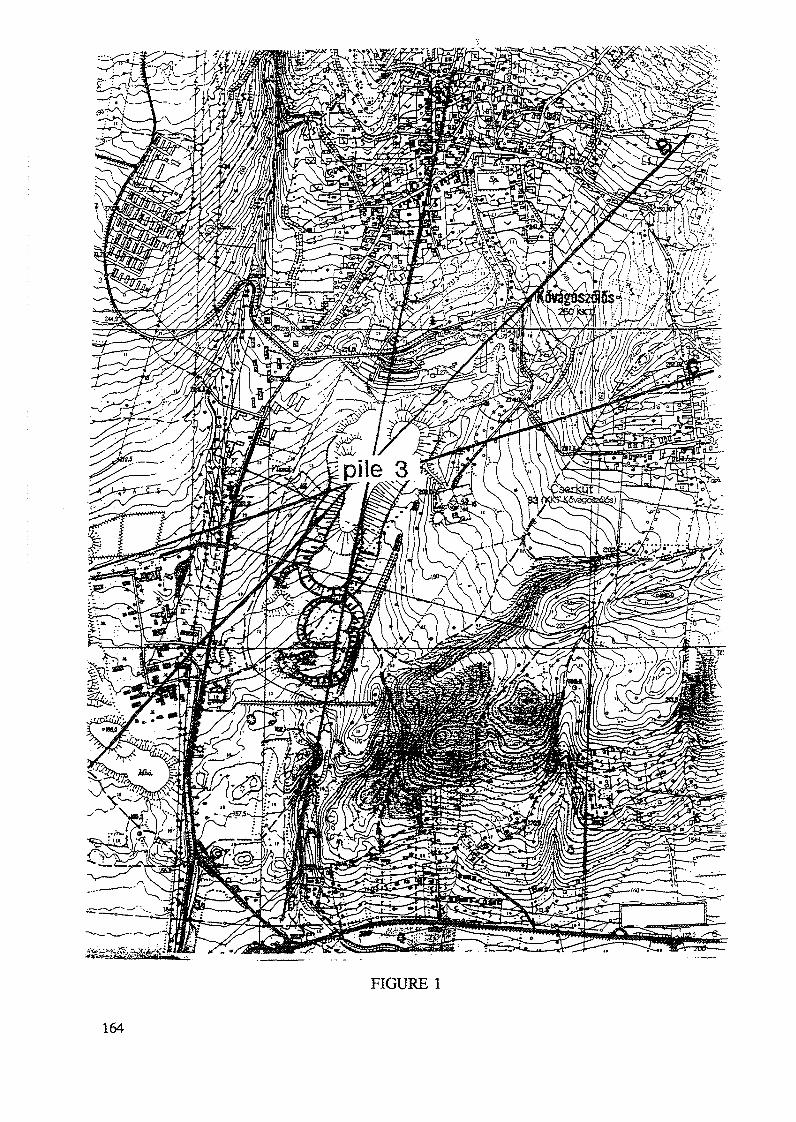
FIGURE 1
164
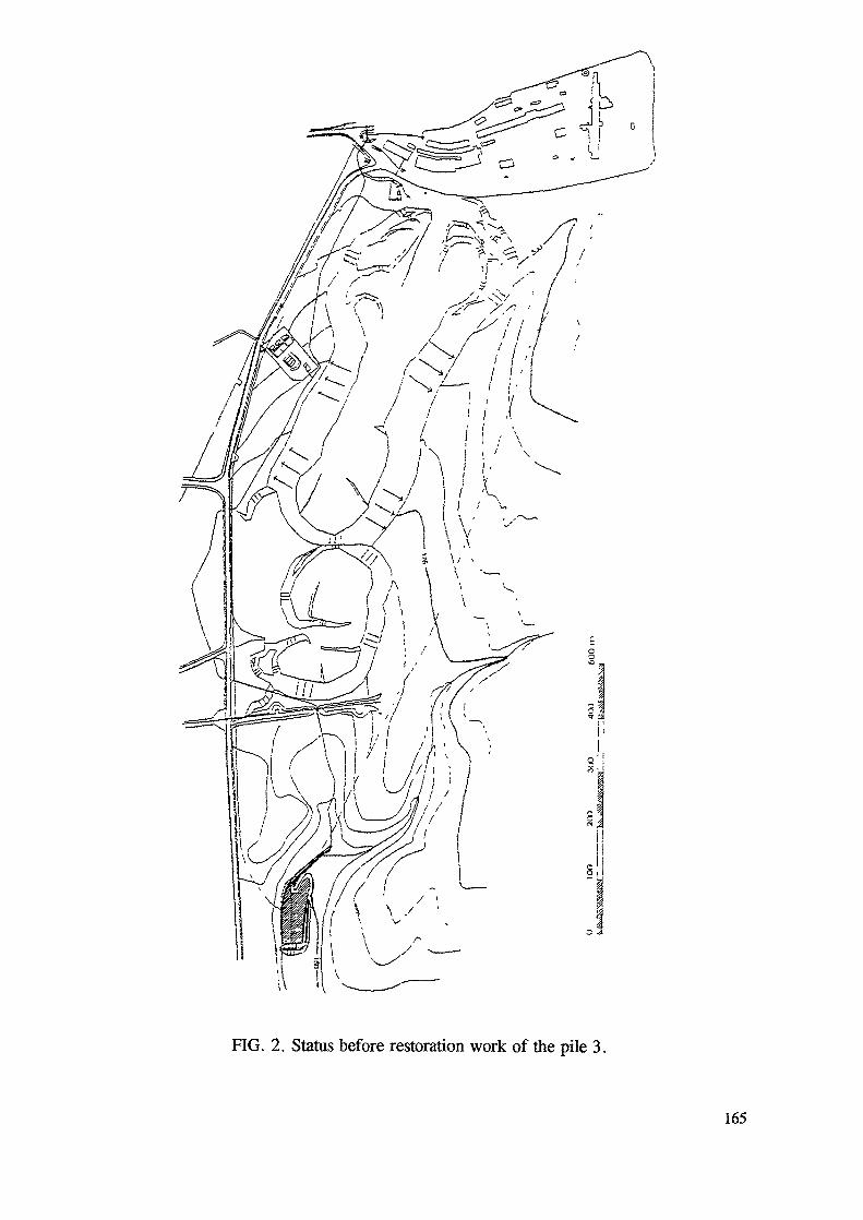
FIG. 2. Status before restoration work of the pile 3.
165
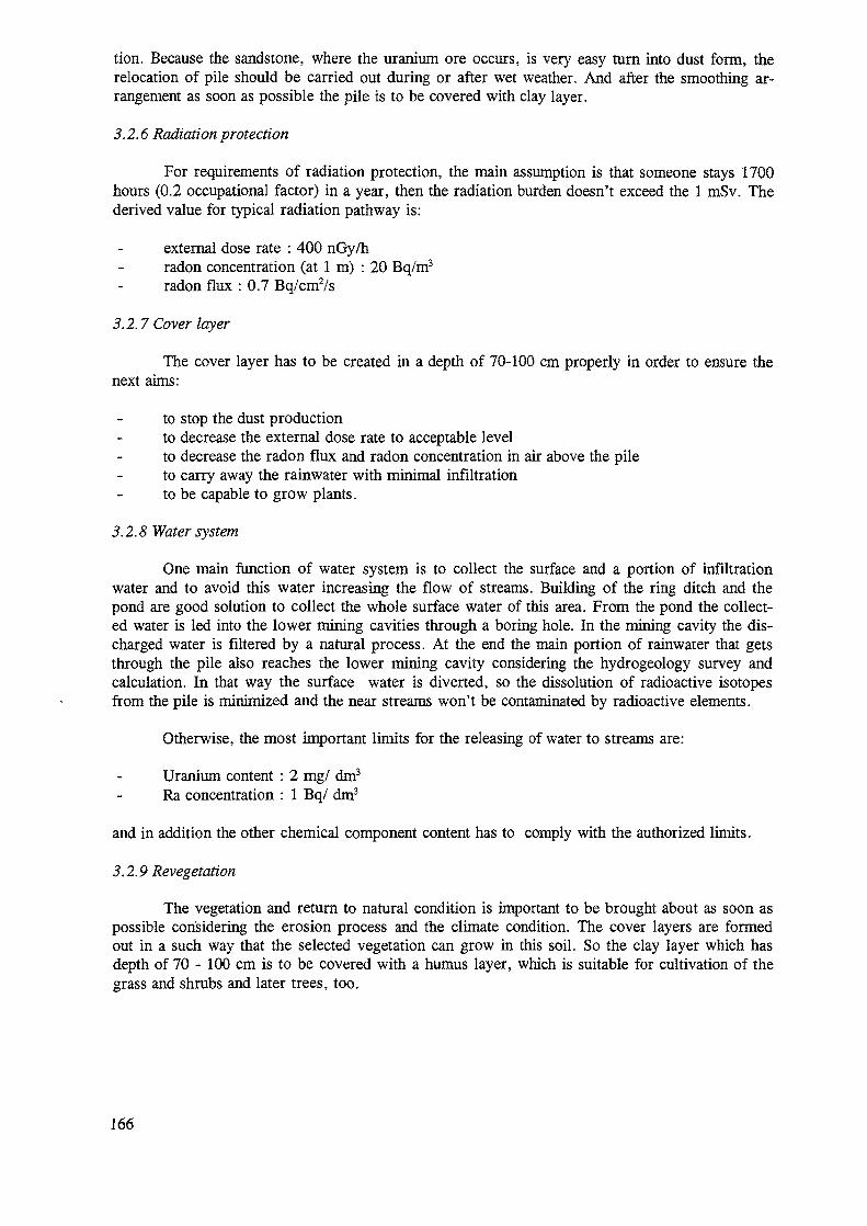
tion. Because the sandstone, where the uranium ore occurs, is very easy turn into dust form, therelocation of pile should be carried out during or after wet weather. And after the smoothing ar-rangement as soon as possible the pile is to be covered with clay layer.
3.2.6 Radiation protection
For requirements of radiation protection, the main assumption is that someone stays 1700hours (0.2 occupational factor) in a year, then the radiation burden doesn't exceed the 1 mSv. Thederived value for typical radiation pathway is:
external dose rate : 400 nGy/hradon concentration (at 1 m) : 20 Bq/m3
radon flux : 0.7 Bq/cm2/s
3.2.7 Cover layer
The cover layer has to be created in a depth of 70-100 cm properly in order to ensure thenext aims:
to stop the dust productionto decrease the external dose rate to acceptable levelto decrease the radon flux and radon concentration in air above the pileto carry away the rainwater with minimal infiltrationto be capable to grow plants.
3.2.8 Water system
One main function of water system is to collect the surface and a portion of infiltrationwater and to avoid this water increasing the flow of streams. Building of the ring ditch and thepond are good solution to collect the whole surface water of this area. From the pond the collect-ed water is led into the lower mining cavities through a boring hole. In the mining cavity the dis-charged water is filtered by a natural process. At the end the main portion of rainwater that getsthrough the pile also reaches the lower mining cavity considering the hydrogeology survey andcalculation. In that way the surface water is diverted, so the dissolution of radioactive isotopesfrom the pile is minimized and the near streams won't be contaminated by radioactive elements.
Otherwise, the most important limits for the releasing of water to streams are:
Uranium content : 2 mg/ dm3
Ra concentration : 1 Bq/ dm3
and in addition the other chemical component content has to comply with the authorized limits.
3.2.9 Revegetation
The vegetation and return to natural condition is important to be brought about as soon aspossible considering the erosion process and the climate condition. The cover layers are formedout in a such way that the selected vegetation can grow in this soil. So the clay layer which hasdepth of 70-100 cm is to be covered with a humus layer, which is suitable for cultivation of thegrass and shrubs and later trees, too.
166
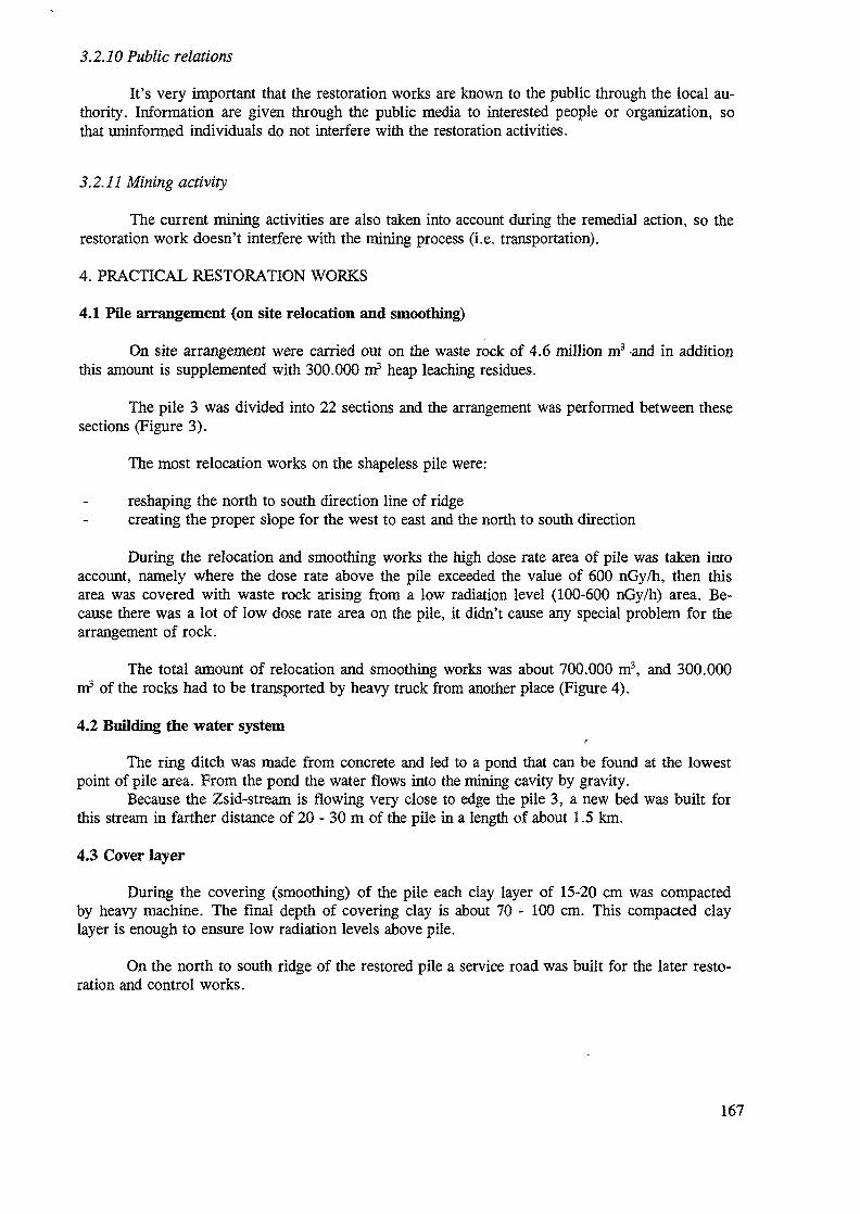
3.2.10 Public relations
It's very important that the restoration works are known to the public through the local au-thority. Information are given through the public media to interested people or organization, sothat uninformed individuals do not interfere with the restoration activities.
3.2.11 Mining activity
The current mining activities are also taken into account during the remedial action, so therestoration work doesn't interfere with the mining process (i.e. transportation).
4. PRACTICAL RESTORATION WORKS
4.1 Pile arrangement (on site relocation and smoothing)
On site arrangement were carried out on the waste rock of 4.6 million m3 -and in additionthis amount is supplemented with 300.000 m3 heap leaching residues.
The pile 3 was divided into 22 sections and the arrangement was performed between thesesections (Figure 3).
The most relocation works on the shapeless pile were:
reshaping the north to south direction line of ridgecreating the proper slope for the west to east and the north to south direction
During the relocation and smoothing works the high dose rate area of pile was taken intoaccount, namely where the dose rate above the pile exceeded the value of 600 nGy/h, then thisarea was covered with waste rock arising from a low radiation level (100-600 nGy/h) area. Be-cause there was a lot of low dose rate area on the pile, it didn't cause any special problem for thearrangement of rock.
The total amount of relocation and smoothing works was about 700.000 m3, and 300.000m3 of the rocks had to be transported by heavy truck from another place (Figure 4).
4.2 Building the water systemr
The ring ditch was made from concrete and led to a pond that can be found at the lowestpoint of pile area. From the pond the water flows into the mining cavity by gravity.
Because the Zsid-stream is flowing very close to edge the pile 3, a new bed was built forthis stream in farther distance of 20 - 30 m of the pile in a length of about 1.5 km.
4.3 Cover layer
During the covering (smoothing) of the pile each clay layer of 15-20 cm was compactedby heavy machine. The final depth of covering clay is about 70 - 100 cm. This compacted claylayer is enough to ensure low radiation levels above pile.
On the north to south ridge of the restored pile a service road was built for the later resto-ration and control works.
167
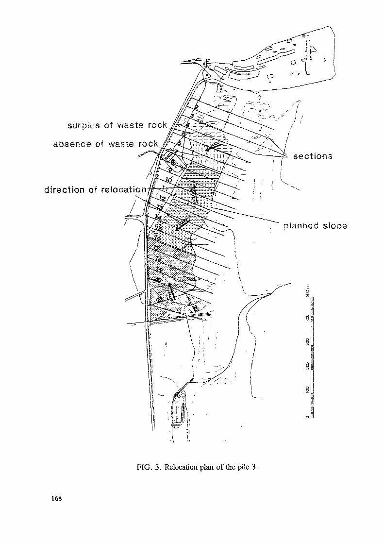
surolus of waste rock
absence of waste rock
direction of relocation^
planned slope
FIG. 3. Relocation plan of the pile 3.
168
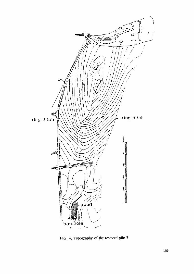
ring ditch
a ? 1 1 Vborehole
FIG. 4. Topography of the restored pile 3.
169
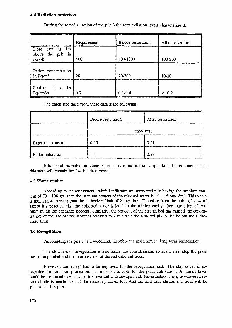
4.4 Radiation protection
During the remedial action of the pile 3 the next radiation levels characterize it:
Dose rate at 1mabove the pile innGy/h
Radon concentrationin Bq/m3
Radon f lux inBq/cm2/s
Requirement
400
20
0.7
Before restoration
100-1800
20-300
0.1-0.4
After restoration
100-200
10-20
< 0.2
The calculated dose from these data is the following:
External exposure
Radon inhalation
Before restoration After restoration
mSv/year
0.95
1.3
0.21
0.27
It is stated the radiation situation on the restored pile is acceptable and it is assumed thatthis state will remain for few hundred years.
4.5 Water quality
According to the assessment, rainfall infiltrates an uncovered pile having the uranium con-tent of 70 - 100 g/t, then the uranium content of the released water is 10 - 15 mg/ dm3. This valueis much more greater than the authorized limit of 2 mg/ dm3. Therefore from the point of view ofsafety it's practical that the collected water is led into the mining cavity after extraction of ura-nium by an ion exchange process. Similarly, the removal of the stream bed has caused the concen-tration of the radioactive isotopes released to water near the restored pile to be below the autho-rized limit.
4.6 Revegetation
Surrounding the pile 3 is a woodland, therefore the main aim is long term remediation.
The slowness of revegetation is also taken into consideration, so at the first step the grasshas to be planted and then shrubs, and at the end different trees.
However, soil (clay) has to be improved for the revegetation task. The clay cover is ac-ceptable for radiation protection, but it is not suitable for the plant cultivation. A humus layercould be produced over clay, if it's overlaid with sewage mud. Nevertheless, the grass-covered re-stored pile is needed to halt the erosion process, too. And the next time shrubs and trees will beplanted on the pile.
170
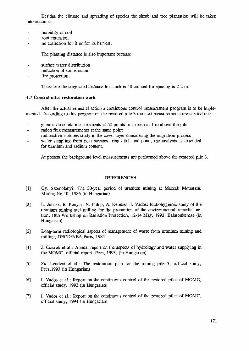
Besides the climate and spreading of species the shrub and tree plantation will be takeninto account:
humidity of soilroot extensionno collection for it or for its harvest.
The planting distance is also important because
surface water distributionreduction of soil erosionfire protection.
Therefore the suggested distance for stock is 40 cm and for spacing is 2.2 m.
4.7 Control after restoration work
After the actual remedial action a continuous control measurement program is to be imple-mented. According to this program on the restored pile 3 the next measurements are carried out:
gamma dose rate measurements at 50 points in a mesh at 1 m above the pileradon flux measurements at the same pointradioactive isotopes study in the cover layer considering the migration processwater sampling from near streams, ring ditch and pond, the analysis is extendedfor uranium and radium content.
At present the background level measurements are performed above the restored pile 3.
REFERENCES
[1] Gy. Szomolanyi: The 30-year period of uranium mining at Mecsek Mountain,Mining No. 10 ,1986 (in Hungarian)
[2] L. Juhasz, B. Kanyar, N. Fulop, A. Kerekes, I. Vados: Radiohygienic study of theuranium mining and milling for the promotion of the environmental remedial ac-tion, 18th Workshop on Radiation Protection, 12-14 May, 1993, Balatonkenese (inHungarian)
[3] Long-term radiological aspects of management of waste from uranium mining andmilling, OECD/NEA,Paris, 1984
[4] J. Csicsak et al.: Annual report on the aspects of hydrology and water supplying inthe MOMC, official report, Pecs, 1993, (in Hungarian)
[5] Zs. Lendvai et al.: The restoration plan for the mining pile 3, official study,Pecs, 1993 (in Hungarian)
[6] I. Vados et al.: Report on the continuous control of the restored piles of MOMC,official study, 1993 (in Hungarian)
[7] I. Vados et al.: Report on the continuous control of the restored piles of MOMC,official study, 1994 (in Hungarian)
171
A PROJECT CARRIED OUT IN ITALY TO SECURE A SITECONTAMINATED BY Cs-137 OF UNKNOWN ORIGIN
C. COCHI, G. MASTINGENEA/AMB/STRA,Italy
Abstract
This paper describes the final phase of the works carried out to secure the industrial wastedisposal situated near Brescia (Italy) contaminated by Csl37 of unknown origin, andrepresents the logical continuation of the papers presented at the Budapest and PiestanyWorkshops.
After the campaign survey undertaken to evaluate the amount of the radioactivity on thesurface of the facility, the deposition of a first coating, in order to temporary stabilize andimmobilize radioactive contamination, and the drilling campaign undertaken to investigatethe quantity and the distribution of the contamination inside the mass of waste, the wholesurface of the waste disposal was eventually coated with a physical cover and protectedwith an erosion control net.
In particular, the lecture focuses on the technologies involved, the description of theworks undertaken and the results obtained.
INTRODUCTION
The matter of this report is the description of the final intervention carried out in order tosecure an industrial waste disposal contaminated by Csl37 of unknown origin.
It is useful, anyway, to briefly remind here the main steps of the intervention alreadyreported in the Budapest and Piestany Workshops.
The contamination of the site was evidenced by geochemical and administrative controlsstarted during the second part of 1989, after an increase of Csl37 in the water of Poriver, just near the nuclear Power Plant of Caorso (Piacenza, Italy), had been pointed outduring some routine controls. The level recorded was about five times the backgroundvalue: so, even if that value was far below the safety limit, the presence of thatradioisotope in the power plant site of Caorso was immediately monitored, but lucidly nocontamination was there evidenced. By Csl37/Csl34 ratio determination, it became thenclear that the radiocontamination could not be due to any fission products correlated withused nuclear fuel, and then with any nuclear power plant accidents (Chernobyl included).
Using a well known geochemical survey method applied to the local river network it waspossible, going upstream from the signalized place on Po river, to locate the source of the
173
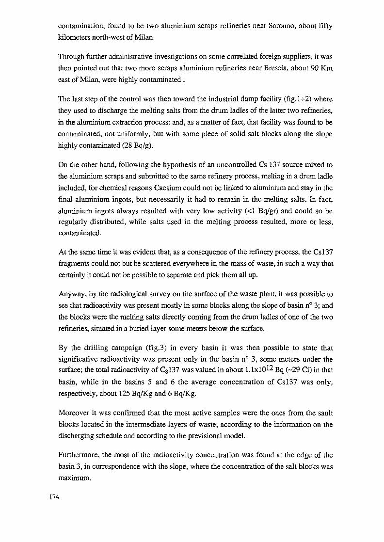
contamination, found to be two aluminium scraps refineries near Saronno, about fiftykilometers north-west of Milan.
Through further administrative investigations on some correlated foreign suppliers, it wasthen pointed out that two more scraps aluminium refineries near Brescia, about 90 Kmeast of Milan, were highly contaminated.
The last step of the control was then toward the industrial dump facility (fig. 1- -2) wherethey used to discharge the melting salts from the drum ladles of the latter two refineries,in the aluminium extraction process: and, as a matter of fact, that facility was found to becontaminated, not uniformly, but with some piece of solid salt blocks along the slopehighly contaminated (28 Bq/g).
On the other hand, following the hypothesis of an uncontrolled Cs 137 source mixed tothe aluminium scraps and submitted to the same refinery process, melting in a drum ladleincluded, for chemical reasons Caesium could not be linked to aluminium and stay in thefinal aluminium ingots, but necessarily it had to remain in the melting salts. In fact,aluminium ingots always resulted with very low activity (<1 Bq/gr) and could so beregularly distributed, while salts used in the melting process resulted, more or less,contaminated.
At the same time it was evident that, as a consequence of the refinery process, the Csl37fragments could not but be scattered everywhere in the mass of waste, in such a way thatcertainly it could not be possible to separate and pick them all up.
Anyway, by the radiological survey on the surface of the waste plant, it was possible tosee that radioactivity was present mostly in some blocks along the slope of basin n° 3; andthe blocks were the melting salts directly coming from the drum ladles of one of the tworefineries, situated in a buried layer some meters below the surface.
By the drilling campaign (fig.3) in every basin it was then possible to state thatsignificative radioactivity was present only in the basin n° 3, some meters under thesurface; the total radioactivity of CS137 was valued in about l.lxlO12 Bq (-29 Ci) in thatbasin, while in the basins 5 and 6 the average concentration of Csl37 was only,respectively, about 125 Bq/Kg and 6 Bq/Kg.
Moreover it was confirmed that the most active samples were the ones from the saultblocks located in the intermediate layers of waste, according to the information on thedischarging schedule and according to the previsional model.
Furthermore, the most of the radioactivity concentration was found at the edge of thebasin 3, in correspondence with the slope, where the concentration of the salt blocks wasmaximum.
174
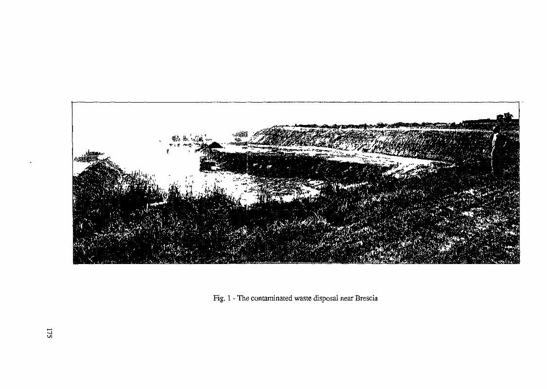
Fig. 1 - The contaminated waste disposal near Brescia
C/t
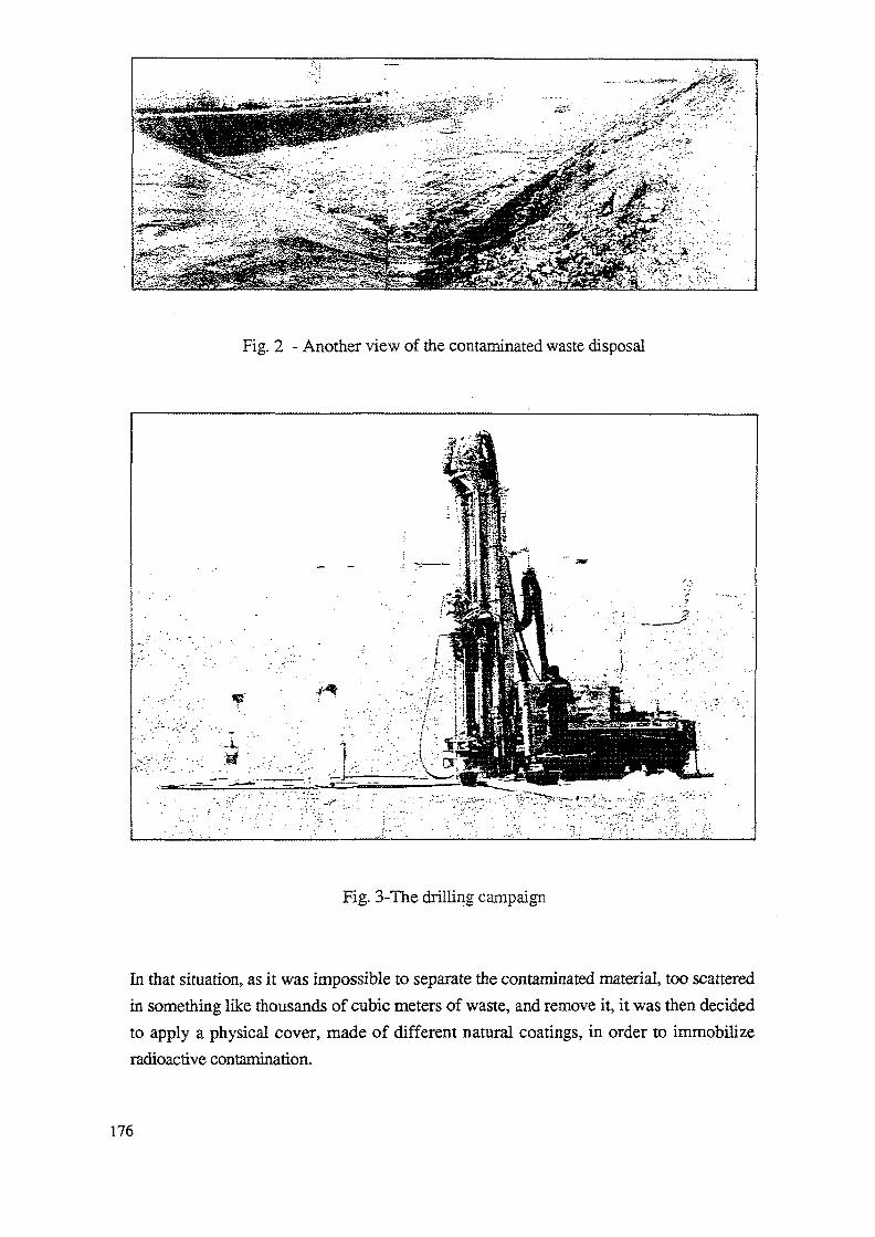
Fig. 2 - Another view of the contaminated waste disposal
Fig. 3-The drilling campaign
In that situation, as it was impossible to separate the contaminated material, too scatteredin something like thousands of cubic meters of waste, and remove it, it was then decidedto apply a physical cover, made of different natural coatings, in order to immobilizeradioactive contamination.
176
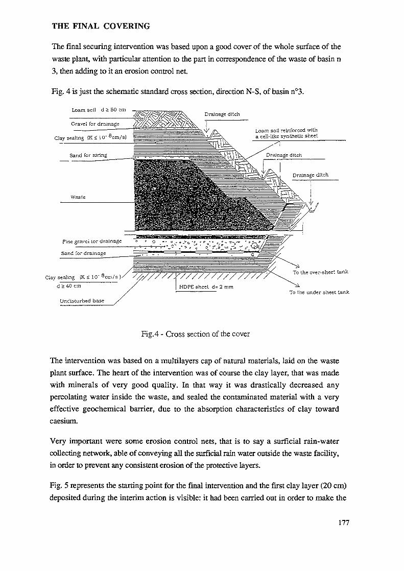
THE FINAL COVERING
The final securing intervention was based upon a good cover of the whole surface of thewaste plant, with particular attention to the part in correspondence of the waste of basin n3, then adding to it an erosion control net
Fig. 4 is just the schematic standard cross section, direction N-S, of basin n°3.
Loam soil d 2 50 cmDrainage ditch
Clay sealing (K < 10' 8cm/s)Loam soil reinforced witha cell-like synthetic sheet
Fine gravel lor drainage o . o ^-
Clay sealing (K < 10" 8cm/s )d > 40 cm
Undisturbed base
the over-sheet tank
To the under sheet lank
Fig. 4 - Cross section of the cover
The intervention was based on a multilayers cap of natural materials, laid on the wasteplant surface. The heart of the intervention was of course the clay layer, that was madewith minerals of very good quality. In that way it was drastically decreased anypercolating water inside the waste, and sealed the contaminated material with a veryeffective geochemical barrier, due to the absorption characteristics of clay towardcaesium.
Very important were some erosion control nets, that is to say a surficial rain-watercollecting network, able of conveying all the surficial rain water outside the waste facility,in order to prevent any consistent erosion of the protective layers.
Fig. 5 represents the starting point for the final intervention and the first clay layer (20 cm)deposited during the interim action is visible: it had been carried out in order to make the
177
Fig. 5 - The situation after the interim intervention
surface of the site safe from the radiological point of view, and in order to let people andvehicles go freely all around to take measurements and samples.
The new layers were deposited after a scarification of the whole previous surface, in orderto link them to the mentioned first clay layer. Then, three more clay layers, 20 cm each,were deposited in correspondence of the basin n° 3, and one clay layer, same depth, incorrespondence of the other basins (fig. 6).
The works were carried out according to a proper planning: the whole area involved wasdivided in twenty-four portions, and for each of them the duration, the beginning and thetype of works planned.
Great care was placed in the sequence of actions, in order to expose every clay layer to aironly for a short time.
Moreover, some precautions against risks of swelling that could rise for gas productioninside the mass of waste were taken by interposing a thin sand-gravel layer between theclay and loam layers on the top, and between the waste and clay layer in the middle, bothconnected with some proper ventilation openings.
The upper layer consisted in a continuous deposition of 5CN-80 cm loam soil layer, on whichsome grass was planted.
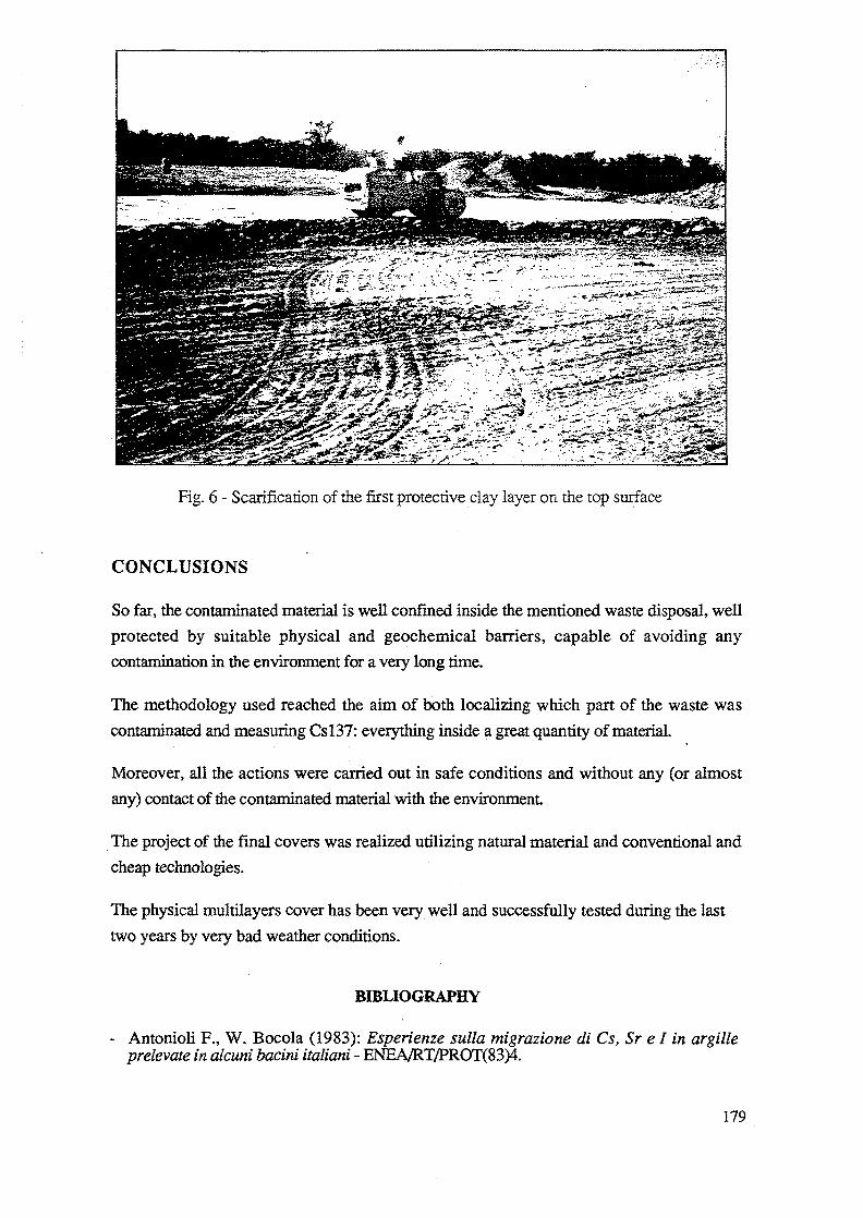
Fig. 6 - Scarification of the first protective clay layer on the top surface
CONCLUSIONS
So far, the contaminated material is well confined inside the mentioned waste disposal, wellprotected by suitable physical and geochemical barriers, capable of avoiding anycontamination in the environment for a very long time.
The methodology used reached the aim of both localizing which part of the waste wascontaminated and measuring Csl37: everything inside a great quantity of material.
Moreover, all the actions were carried out in safe conditions and without any (or almostany) contact of the contaminated material with the environment
The project of the final covers was realized utilizing natural material and conventional andcheap technologies.
The physical multilayers cover has been very well and successfully tested during the lasttwo years by very bad weather conditions.
BIBLIOGRAPHY
- Antonioli F., W. Bocola (1983): Esperienze sulla migrazione di Cs, Sr e I in argilleprelevate in alcuni bacirti italiani - ENEA/RT/PROT(83)4.
179
Antonioli F. et al.(1985): Element diffusion and oxidation phenomena along permeablefractures in clay formations at Monterotondo, Italy - Proceedings of the InternationalClay Conference, Denver, 1985 - The Clay Minerals Society, Bloomington, Indiana,415-421(1987).Beone G., Carbone A. I., Zagaroli M.: La bonifica di aree contaminate -ENEA/RT/PAS/88/31.
Carlsson S. (1978): A model for the movement and loss ofCs!37 in a small watershed -Health Phys. Vol 34, pp 33+37.
Coleman N.T. et al.(1965): Ion exchange displacement of caesium from soil vermiculite- Soil Sci. - Vol. 99, pp. 243-250.
Cochi C. et al. (1989): Programma di intervento per la messa in sicurezza della discaricadi Capriano del Colle (BS) - Messa in sicurezza meteorica - Specifica tecnica - ENEA-AMB-RIF-CRIACpchi C. et al. (1990): Programma di intervento per la messa in sicurezza della discaricadi Capriano del Colle (BS) - Piano di prelevamento di campioni nel corpo della discarica- Prescrizioni tecniche - ENEA- AMB-RIF-CRIA.
Cochi C. et al. (1990): Programma di intervento per la messa in sicurezza della discaricadi Capriano del Colle (BS) - Faselll - Copertura finale - Prescrizioni Tecniche - ENEA-AMB-RIF-CRIA.
Daniel D. et al. (1986): Field permeability test for earthen liners - Proceedings of aSpecialty Conference on Use of in Situ Tests in Geotechnical Enginneering -Geotechnical Special Publication - Samuel P. Clemence Editor - pp. 146-160.
Jones et al. (1986): Development of waste containment structure for Niagara Fallsstorage site - Canadian Nuclear Society: Conference Proceedings of 2nd InternationalConference on Radioactive Waste Management - Sept. 7,11,1986.
Paris P. (1989): Una valutazione di limiti di concentrazione non pericolose per losmaltimento del rifiuti radioattivi in una discarica superficiale - ENEA DISP/SER/NOR-RT(89)6.
Pegoyev A. and Fridman D (1978).: Vertical profiles of caesium 137 in soils - SovietSoil Sci., Vol. 10, pp. 468+472Polyakov Y.A., Kader G.M. and Krintskii V.V. (1973): Behaviour ofSr 90 and Csl37in soils - Radioecology, pp. 78+102. Wiley, New York.
Rogowski A.S., Tamura T.(1970): Environmental mobility ofCs!37 - Radiat. Bot., Vol10, pp. 35+45.
Saltelli A., Antonioli F. (1985): Radioactive -waste disposal in clay formations: asystematic approach to the problem of fractures and faults permeability - RadioactiveWaste Management and Nuclear Fuel Cycle - Volume 6(2), June 1985, pp. 101-120.
Sawhney B.L. (1966): Kinetics of caesium sorption by clay minerals - Soil Sci Soc.Am. Proc., Vol 30, pp. 565+569.
Tamura T. (1964): Selective sorption reactions of caesium with soil minerals - Nucl.Saf., Vol 5, pp. 262+268.
U.O. Fisica e Tutela Ambiente - P.M.I.P. di Milano - U.S.S.L. 75/111 - Sezione diRadioprotezione - Relazione Tecnica: Risultati delle analisi di radiocontamina-zione suicampioni di residuo prelevati presso la discarica Montenetto di Capriano del Colle (BS)- Milano, 8 Novembre 1991
180
TECHNOLOGY FOR RESTORATION OF CONTAMINATEDSITES; REVIEW OF AVAILABLE EXPERIENCE IN THE FIELDOF ENVIRONMENTAL RESTORATION IN ROMANIA
P. SANDRUInstitute of Atomic Physics,Bucharest, Romania
Abstract
In Romania as a result of human activities there are several contaminated sites withlow specific activity widely dispersed. Among these uranium mining and milling, fertilizerindustry and coal-fired power plants are the most significant. Particularly, for heapsresulting from uranium mining and milling activities the environmental restoration isjustified but no comprehensive optimization process (multi-attribute cost benefit analysis)was implemented so far. The lack of specific technology and necessary financial resourcesare major problems in the implementing of environmental restoration work. Regardingcontaminated sites from the fertilizer industry and coal-fired plants the justification forrestoration is not complete. The same difficulty is foreseen with respect to availabletechnology and necessary funds. However, a number of research projects are under developmentand could be considered in the light of international co-operation programmes. Limitedremedial actions were performed in order to do something with respect to smaller areas ofcontamination with higher specific activity.
1. PRELIMINARY
In Romania there are a number of important issues related to environmentalrestoration:
(i) regulatory and scientific aspects; the most important problems are:
a. a clear definition of contaminated sites in terms of specific activity and/oreffective dose;
b. the definition of action levels in terms of specific activity, effective doseor risk values. A definition of action levels in terms of risks appears to bemore appropriate because other associated non-radioactive risks areinvolved. Moreover the heaps from uranium mining and milling activitiespresent potential exposure, which is defined in terms of risk limits and riskconstraints, rather than occupational exposure which is associated with doselimits and dose constraints [1]. In the same way actual regulations [2] offer onlygeneral principles on closing of the extraction activities for raw materials;
c. guidelines for remedial action plan.
(ii) organizational problems associated with a diversity of structures involving humanactivities which could lead to environmental restoration. Due to the lack ofnational and international regulations it is hard to have a consensus on this subject.
181
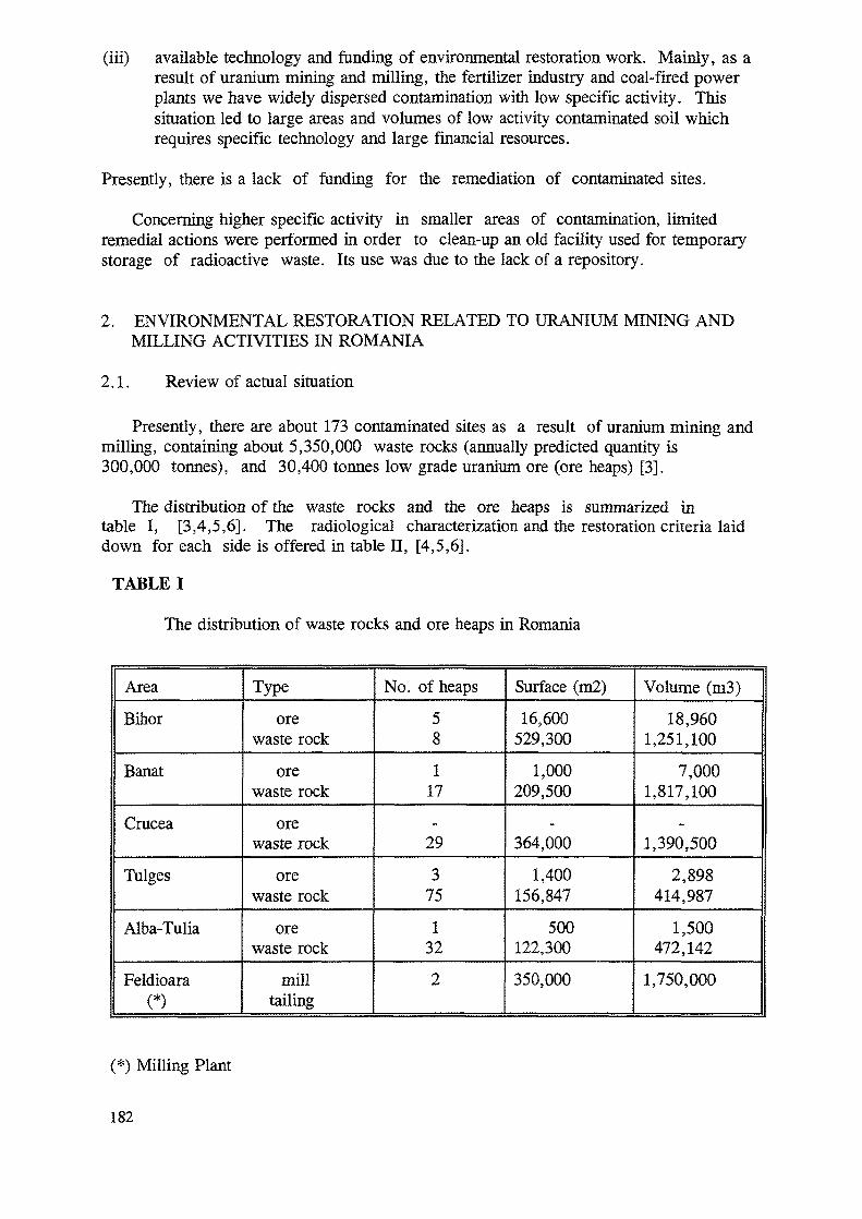
(iii) available technology and funding of environmental restoration work. Mainly, as aresult of uranium mining and milling, the fertilizer industry and coal-fired powerplants we have widely dispersed contamination with low specific activity. Thissituation led to large areas and volumes of low activity contaminated soil whichrequires specific technology and large financial resources.
Presently, there is a lack of funding for the remediation of contaminated sites.
Concerning higher specific activity in smaller areas of contamination, limitedremedial actions were performed in order to clean-up an old facility used for temporarystorage of radioactive waste. Its use was due to the lack of a repository.
2. ENVIRONMENTAL RESTORATION RELATED TO URANIUM MINING ANDMILLING ACTIVITIES IN ROMANIA
2.1. Review of actual situation
Presently, there are about 173 contaminated sites as a result of uranium mining andmilling, containing about 5,350,000 waste rocks (annually predicted quantity is300,000 tonnes), and 30,400 tonnes low grade uranium ore (ore heaps) [3].
The distribution of the waste rocks and the ore heaps is summarized intable I, [3,4,5,6]. The radiological characterization and the restoration criteria laiddown for each side is offered in table II, [4,5,6].
TABLE I
The distribution of waste rocks and ore heaps in Romania
Area
Bihor
Banat
Crucea
Tulges
Alba-Tulia
Feldioara(*)
Typeore
waste rock
orewaste rock
orewaste rock
orewaste rock
orewaste rock
milltailing
No. of heaps58
117
29
375
132
2
Surface (m2)16,600
529,300
1,000209,500
364,000
1,400156,847
500122,300
350,000
Volume (m3)
18,9601,251,100
7,0001,817,100
1,390,500
2,898414,987
1,500472,142
1,750,000
(*) Milling Plant
182
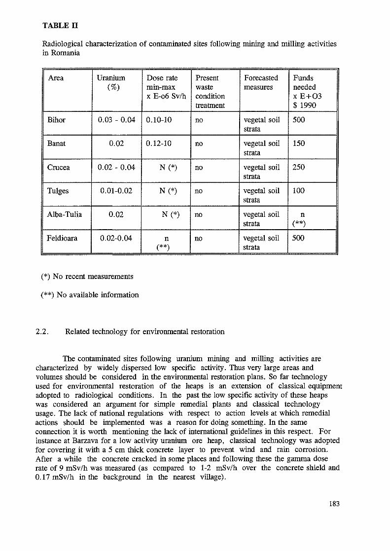
TABLE
Radiological characterization of contaminated sites following mining and milling activitiesin Romania
Area
Bihor
Banat
Crucea
Tulges
Alba-Tulia
Feldioara
Uranium(%)
0.03 - 0.04
0.02
0.02 - 0.04
0.01-0.02
0.02
0.02-0.04
Dose ratemin-maxx E-o6 Sv/h
0.10-10
0.12-10
N(*)
N(*)
N(*)
nc**\
Presentwasteconditiontreatment
no
no
no
no
no
no
Forecastedmeasures
vegetal soilstratavegetal soilstratavegetal soilstrata
vegetal soilstratavegetal soilstrata
vegetal soilstrata
FundsneededxE+O3$ 1990
500
150
250
100
n(**)500
(*) No recent measurements
(**) No available information
2.2. Related technology for environmental restoration
The contaminated sites following uranium mining and milling activities arecharacterized by widely dispersed low specific activity. Thus very large areas andvolumes should be considered in the environmental restoration plans. So far technologyused for environmental restoration of the heaps is an extension of classical equipmentadopted to radiological conditions. In the past the low specific activity of these heapswas considered an argument for simple remedial plants and classical technologyusage. The lack of national regulations with respect to action levels at which remedialactions should be implemented was a reason for doing something. In the sameconnection it is worth mentioning the lack of international guidelines in this respect. Forinstance at Barzava for a low activity uranium ore heap, classical technology was adoptedfor covering it with a 5 cm thick concrete layer to prevent wind and rain corrosion.After a while the concrete cracked hi some places and following these the gamma doserate of 9 mSv/h was measured (as compared to 1-2 mSv/h over the concrete shield and0.17mSv/h in the background in the nearest village).
183
These facts raise the question: for how long a time are these measures appropriate?As time passes the greater the uncertainty becomes. So, variation over thousands ofyears in the meteorological conditions, population distribution, natural disasters andhuman intrusion make our attempts quite difficult. Besides the money needed forclean-up these sites are not available now since other sectors required large amounts offunds.
2.3. Current trends in research and development
Generally, technology is not available and the lack of financial resourcesprecludes large environmental restoration projects.
Currently, there are no national action levels established for remedial actionsrelated to environmental restorations. Moreover, there is no agreed upon definition of acontaminated site. However this situation could be reconsidered through internationalco-operation programmes: IAEA's Coordinated Research Programmes (CRPs) andTechnical Assistance Projects.
On the other hand a number of national research programmes are underdevelopment. Some of these are related with the covering of the heaps resulting from themining and milling industry with a vegetation strata. This should include the followingsteps:
(i) justification: at this stage the environmental restoration is justified for most of theheaps following mining and milling activities,
(ii) optimization: multi-attribute cost-benefit analysis should be carried out
(iii) safety assessment of the site with specification of:
a. possible internal events within the heaps- structural failures- consolidation- radon emanation- direct radiation- chemical hazards
b. possible external events affecting the heap- human intrusion- water erosion- wind erosion- earthquake
c. remedial action plan including- stabilization and consolidation of the heaps- excavation of nearby contaminated soils and placing them on the tops of heaps for
radon flux reduction- choosing layers for control of erosion, infiltration and radon. The top layer will
be vegetation strata which can reduce the visual impact of the remediated heap,
184
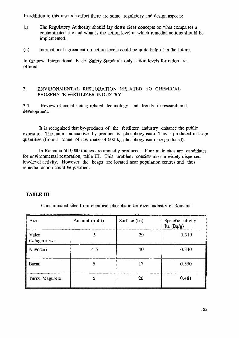
In addition to this research effort there are some regulatory and design aspects:
(i) The Regulatory Authority should lay down clear concepts on what comprises acontaminated site and what is the action level at which remedial actions should beimplemented.
(ii) International agreement on action levels could be quite helpful in the future.
In the new International Basic Safety Standards only action levels for radon areoffered.
3. ENVIRONMENTAL RESTORATION RELATED TO CHEMICALPHOSPHATE FERTILIZER INDUSTRY
3.1. Review of actual status; related technology and trends hi research anddevelopment.
It is recognized that by-products of the fertilizer industry enhance the publicexposure. The main radioactive by-product is phosphogypsum. This is produced in largequantities (from 1 tonne of raw material 600 kg phosphogypsum are produced).
In Romania 500,000 tonnes are annually produced. Four main sites are candidatesfor environmental restoration, table III. This problem consists also in widely dispersedlow-level activity. However the heaps are located near population centres and thusremedial action could be justified.
TABLE HI
Contaminated sites from chemical phosphatic fertilizer industry in Romania
Area
ValeaCalugareascaNavodari
Bacau
Turau Magurele
Amount (mil.t)
5
4-5
5
5
Surface (ha)
29
40
17
20
Specific activityRa (Bq/g)
0.319
0.340
0.530
0.481
185
No site-specific remedial action plan has been prepared so far. Anyhow, actionlevels must take into account:
- the individual and collective exposures,- the radiological and non-radiological risks, and- the financial and social cost.
If remedial actions are justified then further studies on ecological impact andcost-benefit analysis are expected. In any case financial resources are limited and onlysome research studies are under development, so far. Of course, there is no specialtechnology at hand.
4. ENVIRONMENTAL RESTORATION RELATED TO COAL-FIRE POWERPLANTS
4.1. Review of actual status; related technology and trends in research anddevelopment.
The remedial actions concerning the deposition of the fly-ash due toelimination of organic compounds in the thermoelectric power plants is not yetjustified. This case is also one of widely dispersed low specific activity (U-238,Ra-226, Th-232, K-40).
A comprehensive research programme [8] has been implemented since 1983around a number of both old and modern power plants. The individual and collective dosereceived by the population in these areas were assessed. For instance the collectiveeffective committed dose was found between 76 man x Sv/GW annually and 0.24 man xSv/GW annually.
If remedial actions are justified further studies on ecological impact andcost-benefit analysis are expected. In any case financial resources are limited and onlysome research studies are under development, so far. Of course, there is no specialtechnology at hand.
5. CONCLUSIONS
1. The main concern with respect to environmental restoration is widely dispersed lowspecific activity due to uranium mining and milling activities; there are 173 contaminatedsites placed in 6 main regions. The remedial actions are justified in this case but the lackof special technology and financial resources are major problems in the implementing ofenvironmental restoration work. However, a number of technologies are under developmentand could be improved and applied taking into account good experience from othercountries. Thus, IAEA's CRPs and Technical Assistance Projects are welcome in orderto make the remedial actions as cost efficient and successful as possible.
186
2. International Organizations involved in environmental restoration as well asRegulatory Authority should provide guidelines on how to define contaminated sites andrelated action levels.
3. For contaminated sites, the overall problem should be considered includingnon-radioactive risks.
4. Fertilizer industry and coal-fired power plants release large amounts ofby-products and fly-ash with increased concentration of radioactive nuclides. Lowspecific activity is widely dispersed around the facilities. Environmental restorations stillneeds justification, and a number of projects are under development.
5. A number of regulatory and scientific aspects should be defined in the future suchas the contaminated site concept and action level values.
REFERENCES
[1] INTERNATIONAL COMMISSION FOR RADIATIONPROTECTION; ICRP-60: Potential Exposure, 1990.
[2] NATIONAL COMMISSION FOR CONTROL OF NUCLEARACTIVITIES "Republican Nuclear Safety Norms for GeologicalExploration, Mining and Milling of Uranium Ore, 1975 (only inRomanian).
[3] PEIC, T., "Radioactivities Natural a la Extractia Minereuluide Uranium", Rare Metals Autonomous Administration Report (InRomanian), 16nov.l993.
[4] BAJENARU, C., et. al., "The Situation of The Wastes Resultedby Uranium Ore Dressing, Mining Exploitation and GeologicalExploration", Rare Metals Autonomous Administration Report, 1993.
[5] SANDRU, P., "Considerations on Some Radioactive Areasin Romania, Potential Subject for Environmental Restoration", IAEATechnical Co-operation Regional Projects for EnvironmentalRestoration, First Workshop Budapest 4-8 Oct. 1993.
[6] SANDRU, P., "Planning for Environmental Restoration ofContaminated Areas in Romania", IAEA Technical Co-operationProjects for Central and Eastern Europe on EnvironmentalRestoration; Second Workshop, Piestany 11-15 April 1994.
[7] GHILEA, S., COROIANU, A., FEKETE, I., "EnvironmentalRadioactive Contamination Caused by Uranium Ore Mining inRomania", Paper presented at CEC International Symposium onRemediation and Restoration of Radioactive Contaminated Sites inEurope, Antwerp 1993.
187

[8] BOTEZATU, E., TORO, L., BOTEZATU, G., CAPITANU, O., RASCANU,V., AGHIORGHIESEI, D., BALABAN, D., PEIC, T., DINCA, G.,STOICESCU, G., "Coal Fired Power Plants as a Source of PopulationExposure", Radiation Protection National Conference, Oradea 1993.
188
TECHNOLOGIES OF ENVIRONMENTALRESTORATION IN RUSSIA
A.F. NECHAEV, V.V. PROJAEVSt. Petersburg State Institute of Technology,St Petersburg, Russian Federation
Abstract
{n present study the attempt is undertaken to compile, systematize andanalyze the data on technologies of radioactively contaminated sitesrestoration. The principal attention is paid to the methods and tools alreadyemployed in the practical activities. Some generalized considerations andsuppositions on the subject are also presented.
1. INTRODUCTORY REMARKS
The environmental legacy of industrialization and the "cold war" stronglyinfluences both the everyday life of inhabitants and economy of the countries as awhole - that's a truism now. As to the impact of "atomic rubbish," this fact becamean absolutely obvious and even threatening after 1986: to some extent because ofChernobyl catastrophe, directly or indirectly affected predominant majority of thecountries; but mostly because of radical changes in the world political and morale-psychological climate (see in detail [1-3]). In such or another way the curtain ofsecrecy, which concealed the data on the facts associated with the great and oftenuncontrolled radioactive contamination of many sites, was raised, and the problemof nuclear legacy came up in a practical plane. The first and the natural reaction ofthe public, specialists and officials was to restore radioactively contaminated sitesa.s.a,p. As a result, in many countries, including Russia, ambitious environmentalrestoration programs have been developed and approved on the governmentallevels as a high priority activity.
However, very soon it became understandable that these programs requiresuch a great expenditure of material and financial resources which are notavailable even in the highly developed countries. For example, representative of USDOE Mr. C. Frank recently reported that remediation of nuclear weaponsproduction sites in USA will require $600 billion for 30 years. According to [4] thecosts to vitrify nuclear wastes in the former USSR alone will run about $ 500 millionannually in the next ten years, using local personnel, etc.
Enormous cost of site remediation and the financial risk of environmentalliability presented more than serious barriers to cleaning up contaminated properties
Present analytical review is prepared as a contribution to the IAEA TC Project onEnvironmental Restoration in Centra! and Eastern Europe. The views expressed by theauthors do not necessarily reflect those of Government of Russian Federation.
189
and encouraged responsible institutions to build upon undeveloped open space,rather than clean up and reuse these sites.
Thus, initial euphoria was rapidly replaced by very restrained expectations, ifnot by foil skepticism in relation to the original plans of environmental restoration.
However, it looks as if situation can be changed in the nearest future and.at the first glance — quite unexpectedly. Economics again is a key point of the proofsadduced, but from absolutely opposite point of view. To put it briefly, there existsopinion that environmental restoration technologies should be viewed as astimulus, rather than an obstacle, to economical revitalization [5,6]. The proponentsof this concept give an impressionable figures and facts [5-10]:
* the global market for environmental products and services has beenassessed as $ 240 billion in 1993, and it is expected to reach around$600 billion by the year 2000;
* DOE alone has 1.5 million tons of radioactive scrub metal in storagearound the USA, a contaminated heap that is expected to grow at leasttenfold as nuclear weapons facilities are decommissioned. For example, theold Oak Ridge GD Plant contains $ 400-million worth of contaminatednickel to salvage, millions of dollars worth of copper, steel and othermetals, and enough concrete to lay a roadbed from New York City to LosAngeles;
« each 1100 MW light water reactor operated for its full 40-year license life,will generated 18,000 m3 of contaminated metals and concrete, about 98%of which will be the least radioactive form of low-level waste, making thisa market ripe for companies with market - tested cleanup and recyclingtechnologies to deploy;
* the OECD reported Germany to be the leader in environmental exportswith a 1992 surplus of $ 10 billion, followed by the USA with a $ 4billion and Japan with $ 3 billion. The conference on Asia-PacificEconomic Cooperation recently made stimulating green industries alinchpin policy, stating that "...sound environment and sound economicpolicies are mutually supportive" and that "preventing environmentaldegradation is fundamental to sustainable development".
Summarizing all the above described, it is logically to make up a question:what is environmental restoration? The heavy burden of objectively forced, timeand money - consuming technological activities, or profitable business? Apparently,the truth is somewhere in between of these two extreme points of view. The ultimateanswer depends, among others, on the global political climate, and on the concretecombination of technological, economic, environmental and political variables ineach country. It is not difficult to predict that the rates and effectiveness ofenvironmental restoration activities will differ from country to country, and that
190
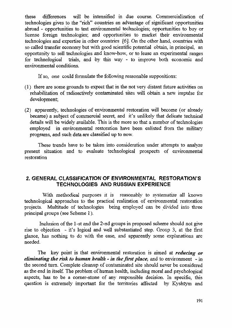
these differences will be intensified in due course. Commercialization oftechnologies gives to the "rich" countries an advantage of significant opportunitiesabroad - opportunities to test environmental technologies; opportunities to buy orlicense foreign technologies; and opportunities to market their environmentaltechnologies and expertise in other countries [6]. On the other hand, countries withso called transfer economy but with good scientific potential obtain, in principal, anopportunity to sell technologies and know-how, or to lease an experimental rangesfor technological trials, and by this way - to improve both economic andenvironmental conditions.
If so, one could formulate the following reasonable suppositions:
(1) there are some grounds to expect that in the not very distant future activities onrehabilitation of radioactively contaminated sites will obtain a new impulse fordevelopment;
(2) apparently, technologies of environmental restoration will become (or alreadybecame) a subject of commercial secret, and it's unlikely that delicate technicaldetails will be widely available. This is the more so that a number of technologiesemployed in environmental restoration have been enlisted from the militaryprograms, and such data are classified up to now.
These trends have to be taken into consideration under attempts to analyzepresent situation and to evaluate technological prospects of environmentalrestoration
2. GENERAL CLASSIFICATION OF ENVIRONMENTAL RESTORATION'STECHNOLOGIES AND RUSSIAN EXPERIENCE
With methodical purposes it is reasonably to systematize all knowntechnological approaches to the practical realization of environmental restorationprojects. Multitude of technologies being employed can be divided into threeprincipal groups (see Scheme 1).
Inclusion of the 1-st and the 2-nd groups in proposed scheme should not giverise to objection - it's logical and well substantiated step. Group 3, at the firstglance, has nothing to do with the case, and apparently some explanations areneeded.
The key point is that environmental restoration is aimed at reducing oreliminating the risk to human health - in the first place, and to environment - inthe second turn. Complete cleanup of contaminated site should never be consideredas the end in itself. The problem of human health, including moral and psychologicalaspects, has to be a corner-stone of any responsible decision. In specific, thisquestion is extremely important for the territories affected by Kyshtym and
191
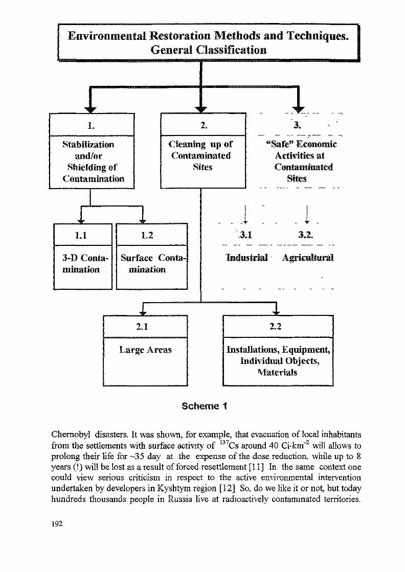
Environmental Restoration Methods and Techniques*General Classification
I1.
Stabilizationand/or
Shielding ofContamination
2.
Cleaning up ofContaminated
Sites
1.1
3-D Conta-mination
1.2
Surface Conta-mination
"Safe" EconomicActivities atContaminated
Sites
3,2.
Industrial Agricultural
2.1
Large Areas
2.2
Installations, Equipment,Individual Objects,
Materials
Scheme 1
Chernobyl disasters. It was shown, for example, that evacuation of local inhabitantsfrom the settlements with surface activity of 137Cs around 40 Ci-knf2 will allows toprolong their life for ~35 day at the expense of the dose reduction, while up to 8years (!) will be lost as a result of forced resettlement [11] In the same context onecould view serious criticism in respect to the active environmental interventionundertaken by developers in Kyshtym region [12] So, do we like it or not, but todayhundreds thousands people in Russia live at radioactively contaminated territories.
192
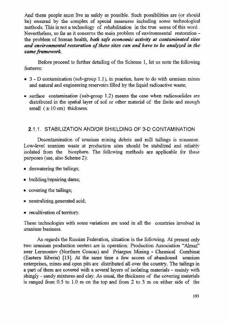
And these people must live as safely as possible. Such possibilities are (or shouldbe) ensured by the complex of special measures including some technologicalmethods. This is not a technology of rehabilitation in the true sense of this word .Nevertheless, so far as it concerns the main problem of environmental restoration -the problem of human health, both safe economic activity at contaminated sitesand environmental restoration of these sites can and have to be analyzed in thesame framework.
Before proceed to further detailing of the Scheme 1, let us note the followingfeatures:
• 3-D contamination (sub-group 1.1), in practice, have to do with uranium minesand natural and engineering reservoirs filled by the liquid radioactive waste;
« surface contamination (sub-group 1.2) means the case when radionuclides aredistributed in the spatial layer of soil or other material of the finite and enoughsmall (n-lOcm) thickness.
2.1.1. STABILIZATION AND/OR SHIELDING OF 3-D CONTAMINATION
Decontamination of uranium mining debris and mill tailings is nonsense.Low-level uranium waste at production sites should be stabilized and reliablyisolated from the biosphere. The following methods are applicable for thesepurposes (see, also Scheme 2):
• deswatering the tailings;
• building/repairing dams;
« covering the tailings;
• neutralizing generated acid;
• recultivation of territory.
These technologies with some variations are used in all the countries involved inuranium business.
As regards the Russian Federation, situation is the following. At present onlytwo uranium production centers are in operation: Production Association "Almaz"near Lermontov (Northern Coucas) and Priargun Mining - Chemical Combinat(Eastern Siberia) [13]. At the same time a few scores of abandoned uraniumenterprises, mines and open pits are distributed all over the country. The tailings ina part of them are covered with a several layers of isolating materials - mainly withshingly - sandy mixtures and clay. As usual, the thickness of the covering materialsis ranged from 0.5 to 1.0 m on the top and from 2 to 3 m on either side of the
193
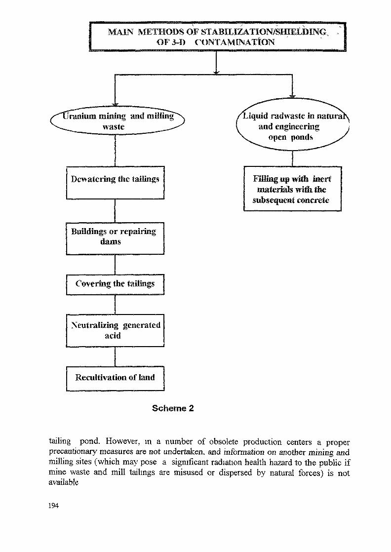
MAIN ^IETHODSOFSTABILIZATION/SfflEtBINCvOF
-is.Jranium mining and miUin:
wasteiquid radwaste in natu
and engineering
Dewalering the tailings
Buildings or repairingdams
Covering the tailings
Neutralizing generatedacid
i
Reactivation of land
Filling iip with later*materials witltihe
subsequent concrete
Scheme 2
tailing pond. However, in a number of obsolete production centers a properprecautionary measures are not undertaken, and information on another mining andmilling sites (which may pose a significant radiation health hazard to the public ifmine waste and mill tailings are misused or dispersed by natural forces) is notavailable
194
Taking into account an importance of the problem discussed, recently specialFederal program was elaborated by the All-Russian Institute of ChemicalTechnology. This program envisages careful inspection of all abandoned productionsites with a subsequent development and implementation of a proper environmentalrestoration technologies. Now this work is in initial stage [13], so that description ofthe methods and techniques expected to be employed is premature.
Natural and engineering open reservoirs contained a thousands and millionscubic meters of high-level liquid radioactive waste - is another type of 3-Dcontaminated sites in Russia [14,15]. Sophisticated technologies of waste processingare not applicable in this case because of enormous volume, unstable andunregulated composition of radioactive water and some other reasons. The onlypossibility to improve radiological situation is mechanical stabilization and shieldingof reservoirs contents.
This labor - consuming work has been started 1.5 years ago at theradiochemical combinat "MAYAK". Natural lake Karatchai contained 400,000 m3
of radioactive waste with a total activity around 120 MCi is gradually filled up with abroken brick and then is covered by concrete. It is difficult to predict now whenthe all ponds in Tchelyabinsk and some other production sites will be shielded (if itis possible at all), and whether the ultimate goal will be reached.
2.1.2. STABILIZATION AND/OR SHIELDING OF SURFACECONTAMINATION
Stabilization and shielding of contaminated surfaces can be applied as aneffective technology practically for any kind of materials/installations in variousconditions. However, in the most cases, the application of surface stabilizers is ashort term action which requires further decontamination. In emergency conditionsof radiological accident stabilization of radionuclides on soils, buildings, roads, etc.is the most essential initial measure.
All the methods of stabilization can be divided into three classes (Scheme 3).The methods used by Russian specialists are reflected in shaded boxes of thescheme.
Chemical technologies elaborated by NIKIMT, VNIIChT, GIPCh and IPhCh,have been employed at Chernobyl site and Bryansk region mostly for dust fixation.A large variety of chemicals has been tested for these purposes. The best resultswere received with compositions on the base of latex and with water-resistancesulfit-cellulose barda,
It should be noted that chemical fixatives (in the form of removal coatings)were effectively used for surface decontamination as well. In specific,polyvinilbutiral (VL-85-03-77) with additives of TCPAA, plastificators and anti-adhesive substances (EAP-30, KEP-2A, OP-7, OP-10) provided decontamination
195
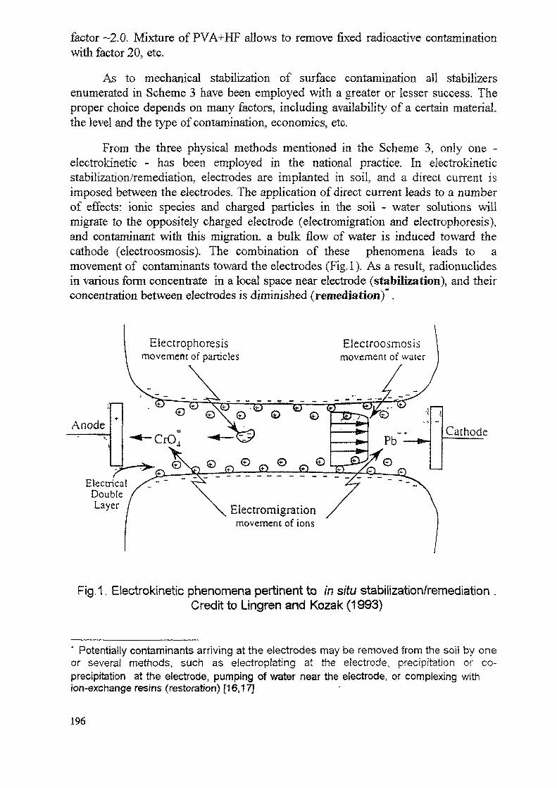
factor ~2.0. Mixture of PVA+HF allows to remove fixed radioactive contaminationwith factor 20, etc.
As to mechanical stabilization of surface contamination all stabilizersenumerated in Scheme 3 have been employed with a greater or lesser success. Theproper choice depends on many factors, including availability of a certain material,the level and the type of contamination, economics, etc.
From the three physical methods mentioned in the Scheme 3, only one -electrokinetic - has been employed in the national practice. In electrokineticstabilization/remediation, electrodes are implanted in soil and a direct current isimposed between the electrodes. The application of direct current leads to a numberof effects: ionic species and charged particles in the soil - water solutions willmigrate to the oppositely charged electrode (electromigration and electrophoresis),and contaminant with this migration, a bulk flow of water is induced toward thecathode (electroosmosis). The combination of these phenomena leads to amovement of contaminants toward the electrodes (Fig. 1). As a result, radionuclidesin various form concentrate in a local space near electrode (stabilization), and theirconcentration between electrodes is diminished (remediation)* .
Electrophoresismovement of particles
Electroosmosismovement of water
ElectricalDoubleLayer Electromigration
movement of ions
Fig.1. Etectrokinetic phenomena pertinent to in situ stabilization/remediation .Credit to Lingren and Kozak (1993)
Potentially contaminants arriving at the electrodes may be removed from the soil by oneor several methods, such as eiectropiating at the electrode, precipitation or co-precipitation at the electrode, pumping of water near the electrode, or comptexing withion-exchange resins (restoration) [16,17]
196
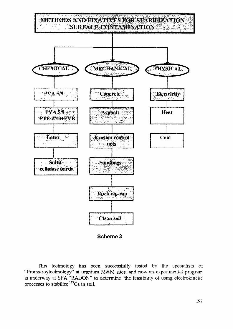
:
Scheme 3
This technology has been successfully tested by the specialists of"Promstroytechnology" at uranium M&M sites, and now an experimental programis underway at SPA "RADON" to determine the feasibility of using electrokineticprocesses to stabilize B7Cs in soil.
197
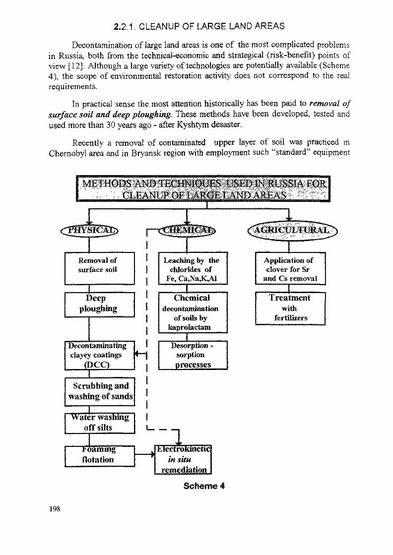
2.2.1. CLEANUP OF LARGE LAND AREAS
Decontamination of large land areas is one of the most complicated problemsin Russia, both from the technical-economic and strategical (risk-benefit) points ofview [12]. Although a large variety of technologies are potentially available (Scheme4), the scope of environmental restoration activity does not correspond to the realrequirements.
In practical sense the most attention historically has been paid to removal ofsurface soil and deep ploughing. These methods have been developed, tested andused more than 30 years ago - after Kyshtym desaster.
Recently a removal of contaminated upper layer of soil was practiced mChernobyl area and in Bryansk region with employment such "standard" equipment
': / •V' V v
Removal ofsurface soil
Deepploughing
Decontaminatingclayey coatings
(DCC)
Leaching by titschlorides of
Fe, Ca,Na,K,Al
Chemicaldecontamination
of soils bykaprolactam
I
IDesorption -
sorptionprocesses
Scrubbing andwashing of sands
Water washingoffsilts
jpoamingflotation —— » Eiectroitinetic
in situremediation
Application ofclover for Sr
and Cs removal
Treatmentwith
fertilizers
Scheme 4
198
as graders, scrapers and bulldozers. As usual contaminated earth was moved intopiles and then hauled away in a specially excavated and isolated trenches.
Two problems were met by developers when removal and storage of soilfrom large areas was applied for decontamination purposes:
• first, the problem of safe storage of contaminated soil.For example, examination of underground waste storage in Nikolaevka(Bryansk region) placed at a pine forest (contamination level 60-70 Ci« km"2 )with dimensions 45x40 m and formed by a sand showed that underground waterradiation level did not exceed PL. At the same time it was demonstrated that inNovozybkov area, where the levels of ground water range from 0.5 to 10 m, theproblem of radioactive waste isolation both from ground water and atmosphericfails (to prevent infiltration) is of vital importance and very difficult.
« second, impossibility of the total territory decontamination by thistechnology because of enormous volumes of soil removed.Therefore, in Bryansk region coverage of contaminated soil with clean sand waspracticed as a more effective means of decontamination/stabilization, since it doesnot require its transportation and storage.
Technology of deep ploughing was extensively applied in Kyshtym andBryansk region for the restoration of lands used for agricultural purposes.
In Bryansk region nearly 101 200 ha (14.8%) of all agricultural lands aresituated in a zone with a level 15-40 Ci-km"2 , and 17,000 ha (2.5%) have acontamination exceeding 40 Ci-kmf2. These include 7,300 ha of a ploughed land and9,800 ha of meadows and pastures.
In 1986-1987 in order to decontaminate agricultural lands they werereploughed. Ploughing lands to a depth of 20 cm reduced radiation dose to 1.5-2times. The ploughing with a full overturn of a furrow was more effective whenradionuclides excluded from a 30-cm ploughed layer. It made it possible to reduce137Cs storage in harvested plants. By the end of 1990 lands with contaminationexceeding 40 Ci-km"2 had been banned for agricultural purposes [18].
Nevertheless, deep ploughing, as a method of decontamination, can not berecommended a priory for any soil type, any root depth of plants, etc. In eachconcrete case additional study is required to determine when and if ploughingshould be used as a cleanup technology.
Other physical methods included in Scheme 4 can be considered rather asprospective elaboration than market - tested technologies of environmentalrestoration.
Decontaminating clayey coatings (DCC) on the base of natural clay andclayey minerals are an effective and cheap sorbents, and they are able to form thin
199
films on the surfaces. These properties have been tested in a large-scale in-fieldexperiments with employment of the "standard" military equipment: ARS-14 andARS-14A The following compositions were investigated at Chernobyl site:
* DCC-1 incorporated in a "liquid glass" and peat-extractants;
« DCC-2 contained sulfit-cellulose barda;
* DCC's contained humus extractants.
This method has been assessed as an universal, economic, satisfactory inrespect to decontamination factor and enough simple in technological sense.However, this approach was not used in a "routine" practice of environmentalrestoration.
Good results have been obtained in extended experiments on mechanicalseparation (scrubbing and washing) of the fine sand fraction from the bulk ofcontaminated quartz sand. Standard equipment for sand classifying have been used.It was shown that around 90% of plutonium is concentrated in the separated finefraction, and only 5% - in a coarse sand. The mass ratio "sand-humus" in the soilinvestigated was 2:1.
The specialists of All-Russian Institute of Chemical Technology elaborated andtested in on-site trials prospective methods of radioactive contaminants removal fromthe soil on the basis of
* foaming flotation and
» washing off silts after separation of roots.
In the flotation experiments the fraction with y -activity 2-5 times less than ininitial samples has been obtained with the yield about 70%. Application of hydro-cyclon technology (triple washing of the pulps) made it possible to separate 50-70%of the sand fraction with 25% of initial radioactivity.
As to electrokinetic technology, this subject was already discussed in aprevious chapter.
Chemical, or better to say, physico-chemical methods of soil decontaminationhave been tested on a pilot scale both in Chernobyl zone and Bryansk region. Thedata on decontamination in a settlement of Swyatsk (Novozybkov district) indicatedthe purification of soil amounting to 45% when a decontaminating solution effluentwas applied. This method of chemical purification was assessed, however, as veryexpensive in comparison to a physical one, as 1 m2 costs more than $1 [18]. Therealso exists another problem associated with potential necessity to process a largevolume of the secondary liquid waste, contained both radionuclides and chemicaltoxins. And finally, it is known that from 40% to 90% of the total amount of 137Cs
200
(the most important contaminant at the territories affected by Chernobyl fallout)* ispractically insoluble in water, strongly fixed by soil and couldn't be mobilized evenin hard acid conditions [18,19], what is, undoubtedly, important for evaluation ofchemical methods effectiveness.
Therefore, in spite of good results obtained in experiments with metalchlorides, mixture of mono- and bicarbon acids as well as composition on the baseof bentonit+peat+HNOs +H^O (desorption - sorption process), it is unlikely thatchemical methods will be widely used in a visible future.
R&D on agricultural methods of soil decontamination have been started in theend of 1950s - beginning of 1960s. However, this technique does not appear to beepractical for widespread usage.
As an example it could be mentioned here some experiments with cloverwhich extracts from soil up to 5% of 90Sr and up to 0.5% of 137Cs. But in general,the so called biological or phyto-technology is characterized by relatively loweffectiveness and by large volumes of the secondary plant waste, which requireproper processing/disposal.
In the same context one could mention some other well known measuresapplicable for decreasing of the soil-plant transfer of radioactive isotopes (e.g.,liming for reducing of 90Sr uptake ; treatment with fertilizers for decreasing theuptake of i37Cs; application of ferrocyanides and bioactive substanses to reduce1 'Cs transfer in agricultural products [20, 21], etc.). This subject as well as theproblem of the plants selection will be discussed in detail in Chapter 2.3.
2.2.2. DECONTAMINATION OF EQUIPMENT, BUILDINGS AND PAVEDSURFACES
Russia has an extensive experience in decontamination of various objects inor adjacent to nuclear facilities during normal operations. These knowledge andtechniques have been partly applied to cleanup materials, equipment, buildings andpaved surface after radiological accidents.
However, very soon it became clear that "normal" decontaminationtechnologies and compositions, in the most cases, are too sophisticated and tooexpensive for application on the scale required in an urban environment.
At present this question is solved, at least at practical level. Although, researchin this field still continue, there are a number of able-bodied and effectivetechnologies for cleanup of large contaminated areas. So far as technical principles
" In Bryansk region range of 137Cs contamination is 5-9 mCi-rrf2 while 90Sr contaminationdoes not exceed 0.7 mCi-m'2, and the level of Pu-isotopes activities is no more than 0.012mCi-m'2.
201
of technologies discussed are almost the same all over the world, only brief factualdescription is presented below (Scheme 5).
Aqueous methods (based on chemical interaction of decontaminatedmaterials with working solutions) showed low effectiveness for paved surfaces. Thefollowing compositions have been tested in real conditions:
« preparation SF-2U + H2C2O4 + H2O;
* preparation SF-2U + H2C2O4 + EDTA + H2O;
« 1%HC1
« H20 + 0.5%OEDFA+(2-5)%H202
Decontamination factor was a little bit higher than 1.0.
At the same time, aqueous technology- has been successfully applied todecontamination of steel and alloys for recycling purposes. The principalparameters of the process are the following:
* decontaminant - (5-25%) HBF4
* temperature - from 40 to 90° C
* duration of processing - from 4 to 6 hours
« decontamination factor - from 10 to 100.
Non-aqueous (mechanical) methods have been used for cleanup of large areasthe most intensively. In sweeping and vacuum sweeping technologies the followingequipment were employed:
* facility "Typhoon"
* water-vacuum cleaning machine KU-005
* whirlwind decontamination facility VDU
« industrial vacuum-cleaner PO-11M
» aerosol vacuum-sweeper on the base of the truck KRAZ-256
* equipment of'^Nuclear Services'*.
Abrasive jet cleaning technology has been realized with the usage of sand asan abrasive, and with employment of the standard machine OM-22612.Decontamination factor did not exceed 6.
202
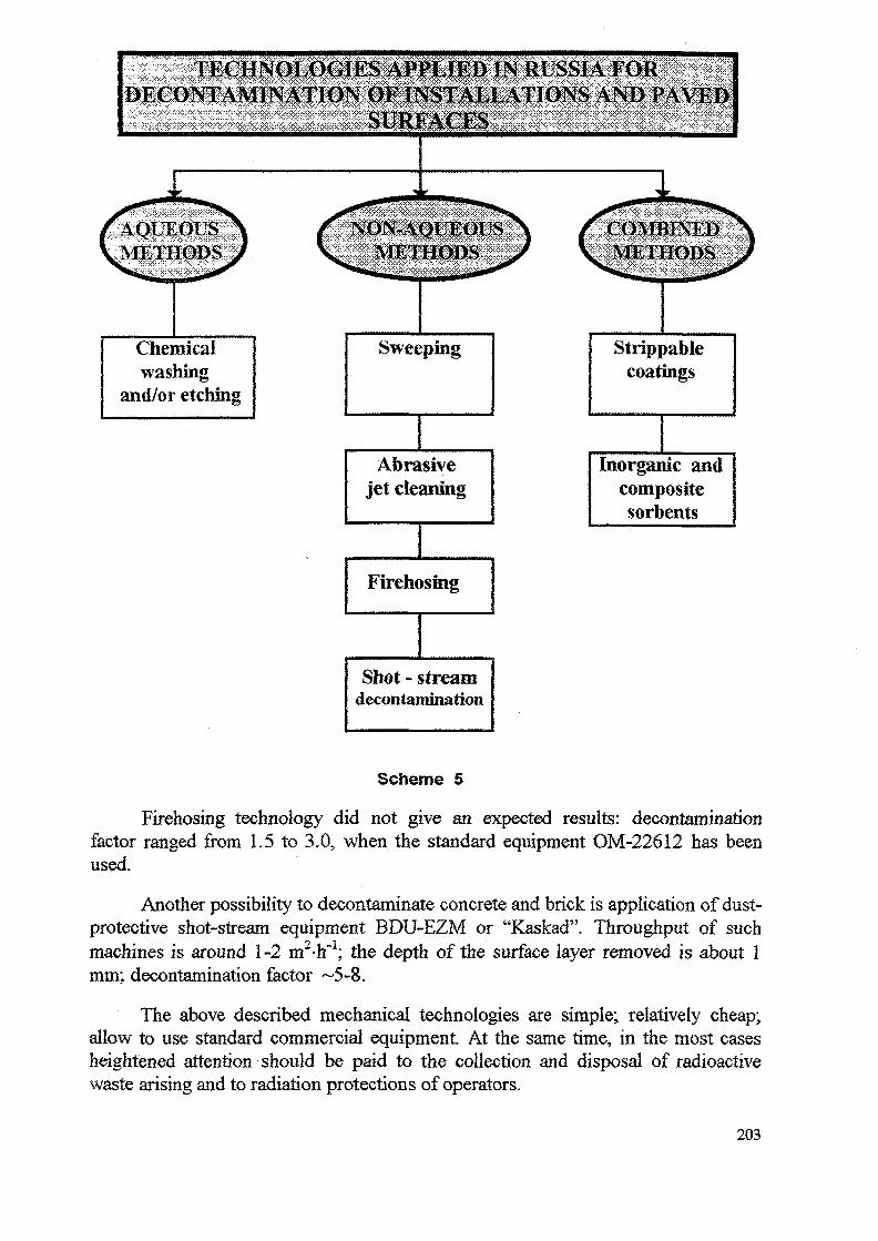
Strippablecoatings
Chemicalwashing
and/or etching
Abrasivejet cleaning
Firehosing
Shot - streamdecontamination
Inorganic andcompositesorbents
Scheme 5
Firehosing technology did not give an expected results: decontaminationfactor ranged from 1.5 to 3.0, when the standard equipment OM-22612 has beenused.
Another possibility to decontaminate concrete and brick is application of dust-protective shot-stream equipment BDU-EZM or "Kaskad". Throughput of suchmachines is around 1-2 m2-h~l; the depth of the surface layer removed is about 1mm; decontamination factor ~5-8.
The above described mechanical technologies are simple; relatively cheap;allow to use standard commercial equipment At the same time, in the most casesheightened attention should be paid to the collection and disposal of radioactivewaste arising and to radiation protections of operators.
203
Strippable coatings and decontaminating clayey coatings, representing theclass of so called combined methods, are described in Chapter 2.1. These coatingscan be applied easily and quickly to large areas and require minimum equipment andpersonnel. Loose contamination is trapped during the curing process and removedwith the layer which is easy to handle and dispose of. Big advantage of DCC is thattheir removal is performed by standard equipment and do not require a manuallabor.
In addition to DCC, special compositions contained inorganic desorbents,have been applied for decontamination purposes. They are the following:
« klinoptilolit + potassium silicate + H2O
* klinoptilolit + H2C2O4 + SF-2U + H2O
« montmorillonit + peat + H2O.
The mechanism of decontamination is based on adhesive - sorptive - ionexchange properties of compositions. This technology allows to removecontaminants from the cracks, clearances, junctions and even from macropores.Decontamination factor depends on the properties of surface and contaminants, andranges from 2 to 5.
In conclusion it is reasonable to note once again that decontamination of lai geobjects, equipment and paved surfaces is specific task, and positive experienceaccumulated in a 'routine" nuclear activities is not always applicable in this case.
2.3.1. INDUSTRIAL ACTIVITIES AT CONTAMINATED SITES
This subject is highlighted here just in provisional term. Any industrialactivity is strongly regulated by existing norms and rules of radiation protection.There are no exclusions from these regulations even at accidentally contaminatedterritories. However, conversion of the defense industry can leads to necessity (ordesirability) to organize new "non-nuclear" works at the former military or nuclearfuel cycle facilities. For Russia such situation is more than realistic. If so, thequestion will raise about the limits of occupational dose for the personnel of newplants, and consequently - about special procedures of work, about specialprivileges for sta££ and about additional efforts on environmental restoration of thesesites. We must be ready to meet such problems and to solve them properly.
2.3.2. "SAFE" AGRICULTURAL ACTIVITIES AT CONTAMINATED SITES
This unusual but very actual issue has already been mentioned in Chapter 2.1.The first forced and extensive experience in this area was gained after Kyshtym
204
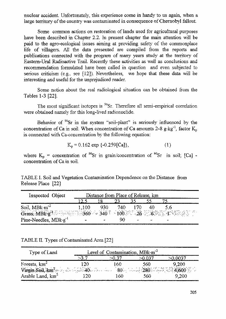
nuclear accident. Unfortunately, this experience come in handy to us again, when alarge temtory of the country was contaminated in consequence of Chernobyl fallout.
Some common actions on restoration of lands used for agricultural purposeshave been described in Chapter 2.2. In present chapter the main attention will bepaid to the agro-ecological issues aiming at providing safety of the commonplacelife of villagers. All the data presented are compiled from the reports andpublications connected with the program of many years study at the territory ofEastern-Ural Radioactive Trail. Recently these activities as well as conclusions andrecommendation formulated have been called in question and even subjected toserious criticism (e.g.. see [12]). Nevertheless, we hope that these data will beinteresting and useful for the unprejudiced reader.
Some notion about the real radiological situation can be obtained from theTables 1-3 [22].
The most significant isotopes is 90Sr. Therefore all semi-empirical correlationwere obtained namely for this long-lived radionuclide.
Behavior of 90Sr in the system "soil-plant" is seriously influenced by theconcentration of Ca in soil. When concentration of Ca amounts 2-8 g-kg'1, factor Kpis connected with Ca-concentration by the following equation:
Kp = 0.162 exp {-0.259[Ca]}, (1)
where Kp = concentration of 90Sr in grain/concentration of 90Sr in soil; [Ca] -concentration of Cain soil.
TABLE I. Soil and Vegetation Contamination Dependence on the Distance fromRelease Place [22]
Inspected Object
Soil, MBk-m'2v ' o ' •• ' f.,v \ S'-.'/'--"/ Ss* VO / ••' '
: Distance from Place of Release, km12.5 18 23 35 55 751,100 930 740 170 40 5.6
Pine-Needles, MBk-g'1 - - 90
TABLE II. Types of Contaminated Area [22]
Type of Land ___Level of Contamination, MBk-m 2
Forests, km2
Arable Land, km2
>3.7120
120
>0.37160
•(WV'Q\jf f "
160
>0.037560
560
XX00379,200
9,200
205
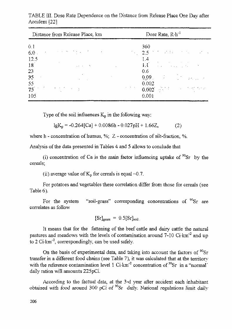
TABLE III. Dose Rate Dependence on the Distance from Release Place One Day afterAccident [22]
Distance from Release Place, km
0.16 : 0 . ' - > • < > ; , -12.518' ' .. , ^23•^5 -5575 " . ' ;
105
Dose Rate, R-h"1
360'-, 2.5 ' " -'— ' ^
1.4LI - , . . . . , - .0.60.09, : ' : - , . -0.0020.002 -; - -0.001
Type of the soil influences Kp in the following way:
IgKp = -0.264[Ca] + 0.0086h - 0.027pH + 1.66Z, (2)
where h - concentration of humus, %; Z - concentration of silt-fraction, %.
Analysis of the data presented in Tables 4 and 5 allows to conclude that
(i) concentration of Ca is the main factor influencing uptake of 90Sr by thecereals;
(ii) average value of Kp for cereals is equal ~0.7.
For potatoes and vegetables these correlation differ from those for cereals (seeTable 6).
For the system "soil-grass" corresponding concentrations of 90Sr arecorrelates as follow
[Sr] = 0.5[Sr3soil.
It means that for the fattening of the beef cattle and dairy cattle the naturalpastures and meadows with the levels of contamination around 7-10 Ci-km"2 and upto 2 Ci-km"2, correspondingly, can be used safely.
On the basis of experimental data, and taking into account the factors of 90Srtransfer in a different food chains (see Table 7), it was calculated that at the territorywith the reference contamination level 1 Ci-km"2 concentration of 90Sr in a "normal"daily ration will amounts 225pCi.
According to the factual data, at the 3-d year after accident each inhabitantobtained with food around 300 pCi of 90Sr daily. National regulations limit daily
206
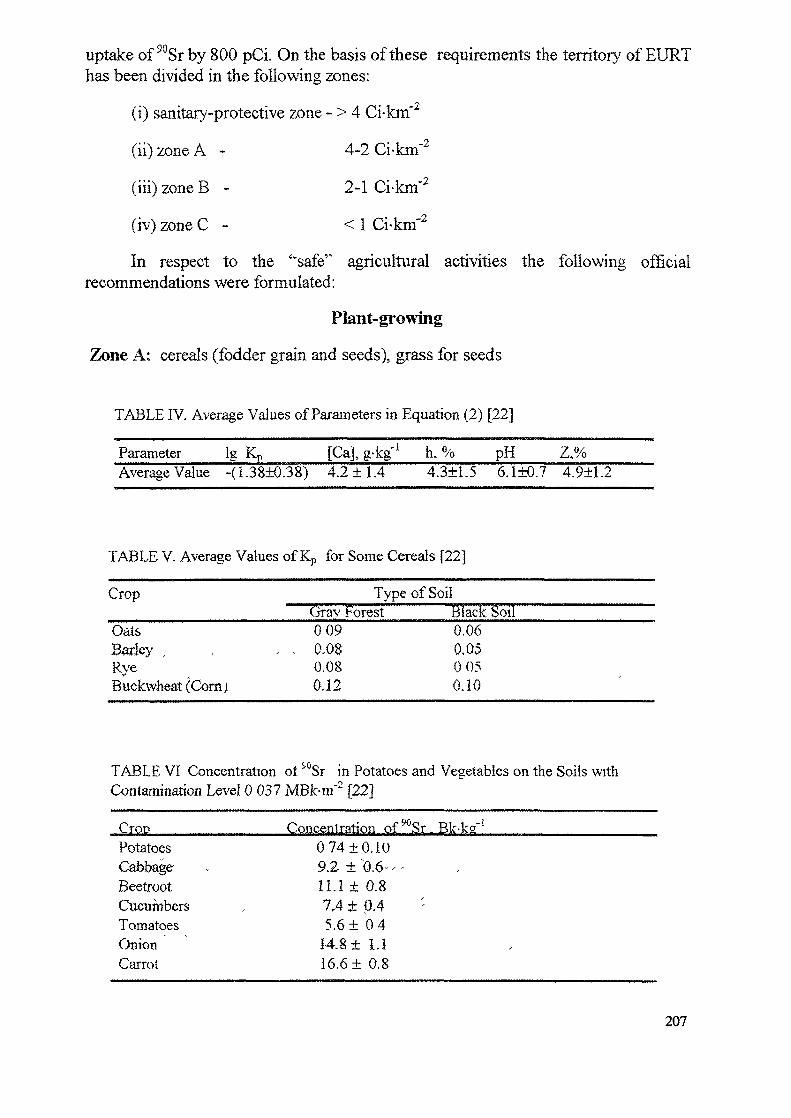
uptake of 90Sr by 800 pCi. On the basis of these requirements the territory of EURThas been divided in the following zones:
(i) sanitary-protective zone - > 4 Ci-kmf2
(ii)zoneA - 4-2 Ci-km"2
(iii) zone B - 2-1 Ci-km"2
(iv) zone C - < 1 Ci-km"2
In respect to the '"safe'' agricultural activities the following officialrecommendations were formulated:
Plant-growing
Zone A: cereals (fodder grain and seeds), grass for seeds
TABLE IV. Average Values of Parameters in Equation (2) [22]
Parameter ig Kp_____[Ca], g-kg'; h. % pH Z.%_____Average Value -(1.38±0.38) 4.2 ±1.4 4.3±1.5 6.1±0.7 4.9±1.2
TABLE V. Average Values of Kp for Some Cereals [22]
Crop
OatsBarley ,RveBuckwheat (Com)
Type of SoilGrav Forest Black Soil0 09 0.06
, , 0.0$ 0,050.08 0 050.12 0.10
TABLE VI Concentration ot Sr in Potatoes and Vegetables on the Soils withContamination Level 0 037 MBk-nf2 [22]
CrooPotatoesCabbage-BeetrootCucumbersTomatoesOnionCarrot
Concentration of90Sr . Bk-ke'1
074 ±0.109.2 ±46--11.1 + 0.87,4 ± 0,45.6 ±04
14.8 ± LI16.6 ± 0.8
207
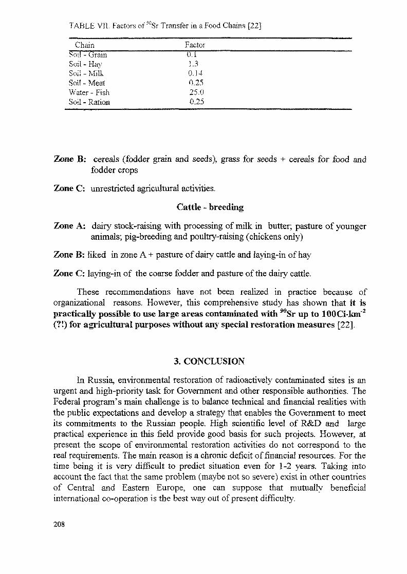
TABLE VII. Factors of "°Sr Transfer in a Food Chains [22]
Chain______________Factor_________Soil - Grain (TISoil-Hay 1.3Soil-Milk 0.14Soil - Meat 0.25Water-Fish 25.0Soil - Ration 0,25
Zone B: cereals (fodder grain and seeds), grass for seeds + cereals for food andfodder crops
Zone C: unrestricted agricultural activities.
Cattle - breeding
Zone A: dairy stock-raising with processing of milk in butter; pasture of youngeranimals; pig-breeding and poultry-raising (chickens only)
Zone B: liked in zone A + pasture of dairy cattle and laying-in of hay
Zone C: laying-in of the coarse fodder and pasture of the daily cattle.
These recommendations have not been realized in practice because oforganizational reasons. However, this comprehensive study has shown that it ispractically possible to use large areas contaminated with Sr up to 100Ci-km"2
(?!) for agricultural purposes without any special restoration measures [22].
3. CONCLUSION
In Russia, environmental restoration of radioactively contaminated sites is anurgent and high-priority task for Government and other responsible authorities. TheFederal program's main challenge is to balance technical and financial realities withthe public expectations and develop a strategy that enables the Government to meetits commitments to the Russian people. High scientific level of R&D and largepractical experience in this field provide good basis for such projects. However, atpresent the scope of environmental restoration activities do not correspond to thereal requirements. The main reason is a chronic deficit of financial resources. For thetime being it is very difficult to predict situation even for 1-2 years. Taking intoaccount the fact that the same problem (maybe not so severe) exist in other countriesof Central and Eastern Europe, one can suppose that mutually beneficia!international co-operation is the best way out of present difficulty.
208
REFERENCES
[I] NECHAEV, A.F., PROJAEV, V.V., "Modem Trends in Education of Radioche-mists-Technologists." (Proc. Intern. Conf. on Nuclear and Hazardous WasteManagement "Spectrum-94", Atlanta, 1994), Vol. 3, ANS Inc., La Grande Park(1994) 1694-1699.
[2] RESTORATION AND ENVIRONMENTAL MANAGEMENT 1994:PROGRESS AND PLANS OF THE ENVIRONMENTAL WASTEMANAGEMENT PROGRAM, Washington D.C. : US DOE (1994) 99.
[3] NECHAEV, A R, PROJAEV, V.V., Conceptual Issues of Practical Radioe-cology Formation. I. Stimuli and Motivation of the Study. J. EcologicalChemistry (1994) in press (in Russian).
[4] ENHANCING US SECURITY THROUGH FOREIGN AID, Washington D.C.Congressional Budget Office (April 1994).
[5] BUCKLES R.J., RAGAINI R.C. "The Commercialization of EnvironmentalTechnologies via Land Reuse Partnerships. "A Cooperative Solution" (Proc.Intern. Conf on Nuclear and Hazardous Waste Management "Spectrum-94"Atlanta, 1994), Vol. 3, ANS Inc., La Grande Park (1994) 2045-2049.
[6] CROWLEY M.E. " The US Role in the International Remediation Market. "ibid. 2050-2053.
[7] SLOWING GROWTH SIGNALS MATURITY OF ENVIRONMENTALINDUSTRY, Press release, Farkas Berkowitz & Company (March 1994).
[8] APEC PLEDGES TO USE ENVIRONMENT AS ECONOMIC STIMULUSTOOL, World Environment Report, Business Publishers Inc., 20, 7 (1994) 55-56.
[9] THE COST OF SHUTTING DOWN, Edison Electric Institute, Washington D.C.(1993).
[10] LEPKOWSKI, W. Export Outlook Modest for Green Technologies, Chemical& Engineering News, 72 14(1994)23.
[II] KULAKOV, V.M., POLEVOY, R.M., PROTASOV, V.M. "About ConceptualIssues of Rehabilitation of the Territories Contaminated with Man-MadeRadionuclides" (Proc. IV Annual Meet and Techn. Conf. of the Nuclear Society,Nizhni Novgorod, 28 June - 2 Jul. 1993), Vol.1, RNS, Nizhni Novgorod (1993)76-78 (in Russian).
[12] PORFIRIEV, B.N. "Strategy of Kyshtym Accident Consequences Mitigation inthe Light of the Risk Conception", Ecological Consequences of RadioactiveContamination on South Ural, Nauka, Moscow (1993) 315-324 (in Russian).
209
[13] SOROKA, Yu. N., KRETININ, A V., MOLTCHANOV, Al., Recultivation ofTerritories Contaminated with Radioactive Waste, Atomic Energy 75 2 (1993)148-155 (in Russian).
[14] KRUGLOV, AK., SMIRNOV, Yu.A. Nuclear Accidents, Their Consequences,and Prospects for Nuclear Power Development, CNIIAtominform, Moscow(1992) 116 (in Russian).
[15]NAZAROV, AG., BURLAKOVA, E.B. el al, Resonans: Conclusions ofExpert Group, SUE, Tchelyabinsk (1991) 55 (in Russian).
[16JACAR, Y.B., ALSHAWABKEN, AN., GALE, R.J, Fundamentals ofExtracting Species from Soils by Electrokinetics, Waste Management 13 (1993)141-151.
[17] REED, B.E., BERG, M.T.,"Removal of Contaminants from Fine Grained SoilsUsing Electrokinetic Flushing", (Rep. DE-FC21-87MC24207) West VirginiaUniversity, Morgantown (1993) 92.
[18] LINNIK, V.G. "Assessment and Prediction of Radioecological Situation UsingGIS-Technology: a Case of Restoration of Radionuclide Contaminated Territoryof Bryansk Region." (Proc. Intern. Conf. on Nuclear and Hazardous WasteManagement "Spectrum-94", Atlanta, 1994), Vol. 3, ANS Inc. , La Grande Park(1994)2069-2072
[19] KONOPLEV, AV, BORZILOV, V.A, BOBOVIKOVA I. L, et. al.Distribution of Radionuclides, Precipitated in Consequence of ChernobylAccident, in the System "Soil-Water", J. Meteorology and Hydrology, 12 (1988)63-74 (in Russian).
[20] VASILIEV, A.K., KRASNOVA, E.G., MOROZOVA LA, etal."Ferrocyanides in the System of Measures Aiming at Production of Clean Stock-Breeding Products at the Territories Contaminated with 137Cs" (Proc. IV AnnualMeet, and Techn. Conf. of the Nuclear Society, Nizhni Novgorod, 28 June - 2 Jul.1993), Vol. 1, RNS, Nizhni Novgorod (1993/194 -196 (in Russian).
[21JULTANENKO, L.N., FILIPAS, AS., TARANENKO, N.S., et. al."Effectiveness of Application of Bioactive Substances for Production of CleanPlant - Growing Products at Radioactively Contaminated Territories" (Proc. IVAnnual Meet, and Techn. Conf. of the Nuclear Society, Nizhni Novgorod, 28 June- 2 Jul. 1993), Vol.1, RNS, Nizhni Novgorod (1993) 189-191 (in Russian).
[22] ANTROPOVA, Z.G., BELOVA, E.I., DIBOLES, I.K., et. al., Main Results andExperience Gained by on Liquidation of Consequences of Emergency LargeAreas Contamination with Uranium Fission Products, Energoatomizdat, Moscow(1990)144.
210
TECHNOLOGIES FOR AND IMPLEMENTATION OFENVIRONMENTAL RESTORATION PROJECT IN THESLOVAK REPUBLIC
O. SLAVIK J. MORAVEKNPP Research Institute, Trnava
M. VLADARResearch Institute of Preventive Medicine,Bratislava
Slovakia
Abstract
This paper represents the logical continuation of those presented at theBudapest and Piestany Worshops. After finishing the monitoring activities inthe contaminated site near Bohunice Nuclear Plant the need for reconsideringthe old restoration project arose. To solve this task new principles for theevaluation of remedial measures was developed in close cooperation with thenational hygiene authorities. This principles as well as the resulting evaluationand proposal of a justified extent of the contaminated banks restoration aredescribed and discussed in the paper.The re-evaluated extent of the banks restoration project include removing andsafe burial of about 1100 m3 of contaminated soil from, and overlaying byclean soil cover on about 10 000 square meters of contaminated flat area ofthes banks. The total cost can be estimated by about US $ 100 000.
1 INTRODUCTION
In Slovakia, no direct experience with the implementation of techniques for a restorationof the environment exists. These problems, however, have been continuously addressed at thedesign level since 1991 in relation to identification of a 137 Cs contamination duringpreparation of a flood control project implementation for an unengineered bank section of theDudvah River (from Bucany to Trakovice).
This section with the length of 2.5 kilometers would extend the engineered downstreamsection (regularly widened and deeped bank profiles) of the Dudvah River (Fig.l), and theprotection against flooding in Trakovice village would thus be resolved.
However, 137Cs contamination was identified not only in this section, but also on thebanks of Manivier canal having discharged released water from the Bohunice Plant Al intoDudvah. A design for removal of the contaminated soils from the banks which wasestablished subsequently thus included also Manivier canal with the expected volume ofdisposed soils of approximately 5000 m3.
Planned decontamination of the banks corresponded to the character of the contaminatedplaces (steep slopes of irregular banks, 90% of 137Cs activity concentration in 15-20 cm thicksurface layer of soil) and to the working limit specified ad hoc by the value of 1 BqI37Cs/gof soil. Prepared design included a surface disposal facility on the Bohunice site theparameters of which were described in a previous work [2J.
211
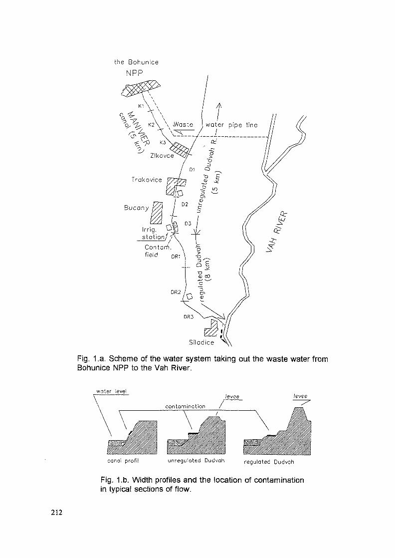
the Bohunice
NPP
Bucony
Irrig.station/'/Contom.field
DR3
Siladice
Fig. 1 .a. Scheme of the water system taking out the waste water fromBohunice NPP to the Vah River.
water levellevee levee
canal profil unregulated Dudvoh regulated Dudvah
Fig. 1.b. Width profiles and the location of contaminationin typical sections of flow.
212
It was found in the course of approving the construction that the most significantproblems of the construction relate to the disposal facility which has not been approved upto now due to a disagreement of the owner of the appropriate land register (Pecenady village).Meanwhile in 1992 to 1994, independently from the design, monitoring activities went on inother non-mapped places of the impacted banks of the Dudvah - Vah river system.
1.1 Finalisation of monitoring of the contaminated site
A 137Cs contamination from the accidentally damaged A-l Bohunice Plant was graduallyidentified also along the entire downstream engineered section of Dudvah River, as well asalong an one kilometer long section in the Vah River flood plain area which formed a mouthdelta of Dudvah River prior to the reconstruction of the flow body.
The contamination in the engineered section of Dudvah River was described in [1]. Onthe present banks of Vah River close to the Siladice village, the contamination used to occurin the places with sediment depositions hi the former Dudvah River's delta bed. Processeddata about 137Cs activity concentration obtained by detailed in-situ mapping of gammaradiation and thickness of sediment/soil layer in 1994 are shown in Tab.l of this work
On these new places, another approximately 11 000 m2 of contaminated surfaces werefound with the average activity concentrations from 1.3 up to 3.7 Bq 137Cs/g of soil. On otherplaces of the Vah River banks, no other contamination was identified by monitoring. Onlyafter completing these monitoring activities, the entire extent of the contamination could beconsidered as a final one. According to the data in [1] and Tab.l, the overall identifiedcontaminated area on the affected banks around Bohunice NPP with the 137Cs activityconcentration above 1 Bq/g is approximately 67 000 m2 and the corresponding volume ofcontaminated soils is about 12 000 m3.
It was gradually recognized that it is impossible to store the entire volume of thecontaminated soils on the Bohunice site due to capacity reasons. In this context, it becamenecessary to reevaluate comprehensively the design of remedial measures in the Bohunicevicinity including all contaminated places on the banks and to account for all circumstancesincluding large costs for the restoration techniques and benefits obtained.
1.2 A comprehensive reconsidering of remedial measures
The objectives of the comprehensive considering of remedial measures for thecontaminated banks were specified as follows:
to propose the implementation of appropriate restoration techniques and of its optimumscope related to the development of proper cleanup criteria based on proposed andauthorized principlesto propose rules for manipulations with below-limit contaminated soils on the banksin case of their transposing during bank maintenance or reconstruction,to propose criteria for the application of less expensive prohibitory and administrativeremedial measures.
The solution is mostly complicated by the fact that a clear legislation is absent in the fieldgiven. Although, an environmental ministry act (1992) exists, where a limit of 137 Cs
213
concentration in soil with a value of 0.5 Bq/g is given for a case of land-field transfer fromthe state to private ownership, it is not usable in the subjected context.
According to the experience with the present solution, as well as with the knowledgeobtained in the course of the solution of this IAEA Project (RER/2/022 EnvironmentalRestoration in Eastern and Central Europe), it was obvious that the choice of restorationtechniques and derivation of proper acceptance levels depend on a number of parameters(dose limits, parameters of scenarios...) that necessarily should be harmonized and clearlydeclared.
It was thus necessary first of all to develop certain principles and rules for evaluation ofthe extent of necessary remedial measures, including development of contaminationacceptance levels, and to achieve their authorization by hygiene authorities. Such principles,as well as the evaluation itself were elaborated recently in the VtJJE Institute and submittedfor comments into the National Institute of Hygiene and Epidemiology (N0HE). After thefirst round of discussions with this authority, in October 1994, it was agreed in this contextthat the ICRP dose limitation system for recovery of contaminated places will be usedaccounting for a net benefit from the implementation of remedial measures or for a reductionof radiation risk below a declared limiting value.
When proposing the scope of remedial measures, it was then possible to start from thefollowing agreed principles:
justification of restoration techniques (cleaning/covering) is conditioned by exceedingthe limit of individual effective dose for public, 1 mSv/y (according to the ICRP/91recomendation) for authorized scenarios with non-zero probability,costs associated with the application of a particular technique decide its choice,decision making about the extent of restoration starts from derived intervention levelsof average 137Cs concentration in soils and of contaminated soil volumes and surfacescomparable with those resulting from corresponding scenarios of radiation risk,
averted detriment from a stay on contaminated banks does not justify theimplementation of cost consuming techniques, its optimization is used for theapplication of less expensive remedial measures, onlythe residual contamination of banks will be considered as a contamination under controlfor the time period of 50 years as a minimum. It will be assured by administrativesteps that a planned translocation of contaminated soils (maintenance, re-engineering)within this whole time is under the control of hygiene authorities.
More detailed results obtained in the application of these principles for the evaluation ofremedial measures and for developing proper cleanup criteria for contaminated banks aredescribed further in the paper.
2 ANALYSIS AND SELECTION OF RADIATION RISKS SCENARIOS
Two stay scenarios were selected for the evaluation of an actual risk from banks and fromcontaminated field, and another two residential scenarios for the evaluation of a potential riskfrom the use of contaminated soils supposed to be fully (about 200 m3) and partially (about50 m3) spread on the site surface around a living house with a garden. Critical individualswere chosen based on an analysis in the following way:
1) a fisherman with the duration of his stay on the bank of 300 hours in sitting position(dose in 30 centimeters above the ground, corrected by the factor of 1.4 against the
214
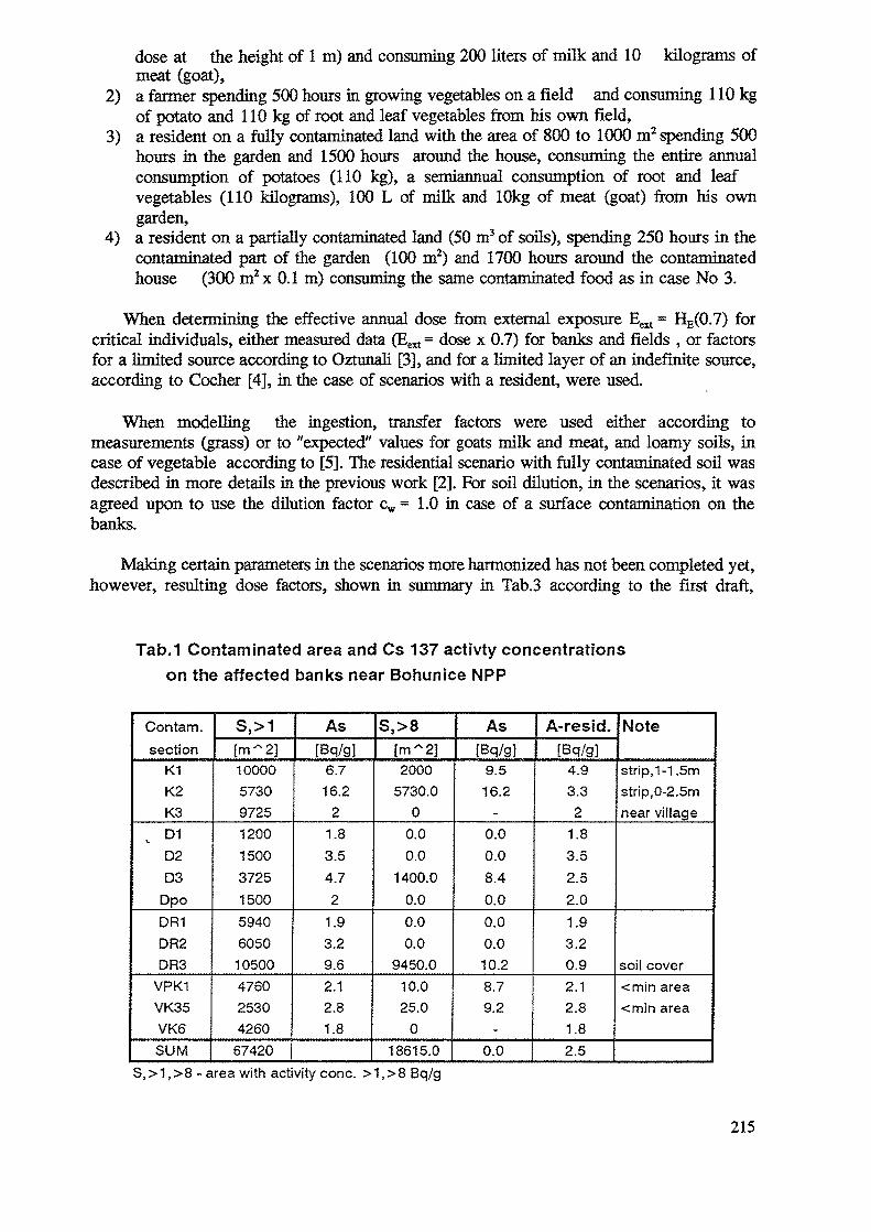
dose at the height of 1 m) and consuming 200 liters of milk and 10 kilograms ofmeat (goat),
2) a farmer spending 500 hours in growing vegetables on a field and consuming 110 kgof potato and 110 kg of root and leaf vegetables from his own field,
3) a resident on a fully contaminated land with the area of 800 to 1000 m2 spending 500hours in the garden and 1500 hours around the house, consuming the entire annualconsumption of potatoes (110 kg), a semiannual consumption of root and leafvegetables (110 kilograms), 100 L of milk and 10kg of meat (goat) from his owngarden,
4) a resident on a partially contaminated land (50 m3 of soils), spending 250 hours in thecontaminated part of the garden (100 m2) and 1700 hours around the contaminatedhouse (300 m2x 0.1 m) consuming the same contaminated food as in case No 3.
When determining the effective annual dose from external exposure Eext = HE(0.7) forcritical individuals, either measured data (Eext = dose x 0.7) for banks and fields , or factorsfor a limited source according to Oztunali [3], and for a limited layer of an indefinite source,according to Cocher [4], hi the case of scenarios with a resident, were used.
When modelling the ingestion, transfer factors were used either according tomeasurements (grass) or to "expected" values for goats milk and meat, and loamy soils, incase of vegetable according to [5], The residential scenario with fully contaminated soil wasdescribed in more details in the previous work [2]. For soil dilution, in the scenarios, it wasagreed upon to use the dilution factor cw = 1.0 in case of a surface contamination on thebanks.
Making certain parameters in the scenarios more harmonized has not been completed yet,however, resulting dose factors, shown hi summary in Tab.3 according to the first draft,
Tab.1 Contaminated area and Cs 137 activty concentratfonson the affected banks near Bohunice NPP
Contam.section
K1K2K3
v D1
D2D3
DpoDR1DR2DR3
VPK1VK35VK6SUM
S,>1[m~2]10000573097251200150037251500594060501050047602530426067420
As[Bq/gJ
6.716.2
21.83.54.72
1.93.29.62.12.81.8
S,>8[m~2]2000
5730.00
0.00.0
1400.00.00.00.0
9450.010.025.0
018615.0
As[Bq/g]
9.516.2
-
0.00.08.40.00.00.010.28.79.2
-0.0
A-resid.[Bq/g]
4.93.32
1.83.52.52.01.93.20.92.12.81.82.5
Note
strip, 1-1 .5mstrip, 0-2.5mnear village
soil cover<min area<min area
S,>1,>8 - area with activity cone. >1,>8 Bq/g
215
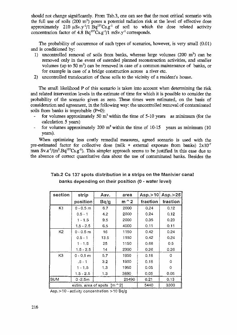
should not change significantly. From Tab.3, one can see that the most critical scenario withthe full use of soils (200 m3) poses a potential radiation risk at the level of effective doseapproximately 210 |iSv.y"Vl Bq^Cs.g"1 of soil to which the dose related activityconcentration factor of 4.8 Bq137Cs.g~Vl mSv.y"1 corresponds.
The probability of occurrence of such types of scenarios, however, is very small (0.01)and is conditioned by:
1) uncontrolled removal of soils from banks, whereas large volumes (200 m3) can beremoved only in the event of extended planned reconstruction activities, and smallervolumes (up to 50 m3) can be removed in case of a common maintenance of banks, orfor example in case of a bridge construction across a river etc.
2) uncontrolled translocation of those soils to the vicinity of a resident's house.
The small likelihood P of this scenario is taken into account when determining the riskand related intervention levels in the estimate of time for which it is possible to consider theprobability of the scenario given as zero. These tunes were estimated, on the basis ofconsideration and agreement, in the following way: the uncontrolled removal of contaminatedsoils from banks is improbable (P=0):
for volumes approximately 50 m3 within the time of 5-10 years as rninimum (for thecalculation 5 years)for volumes approximately 200 m3 within the time of 10-15 years as minimum (10years).
When optimizing less costly remedial measures, agreed scenario is used with thepre-estimated factor for collective dose (milk + external exposure from banks) 2xlO"7
man Sv.a'Vdn^Bq^Cs.g'1). This simpler approach seems to be justified in this case due tothe absence of correct quantitative data about the use of contaminated banks. Besides the
Tab.2 Cs 137 spots distribution in a strips on the Manivier canalbanks depending on their position (0 - water level)
section
K1
K2
K3
SUM
stripposition0-0.5 m0.5- 11-1.5
1.5-2.50 - 0.5 m0.5- 11 - 1.5
1.5-2.50-0.5 m
.5-11 -1.5
1.5-2.50 -2.5m
Aav.Bq/g6.74.29.56.516
13.525145.73.21.31.3
aream~220002000200040001150115011502300195019501950389025490
estim. area of spots [m ~ 2]
Asp.>10fraction
0.240.240.350.110.420.420.680.260.180.180.050.050.215440
Asp.>25fraction
0.120.120.230.110.240.240.5
0.26000
0.050.133300
Asp. > 10 - activity concentration >10 Bq/g
216
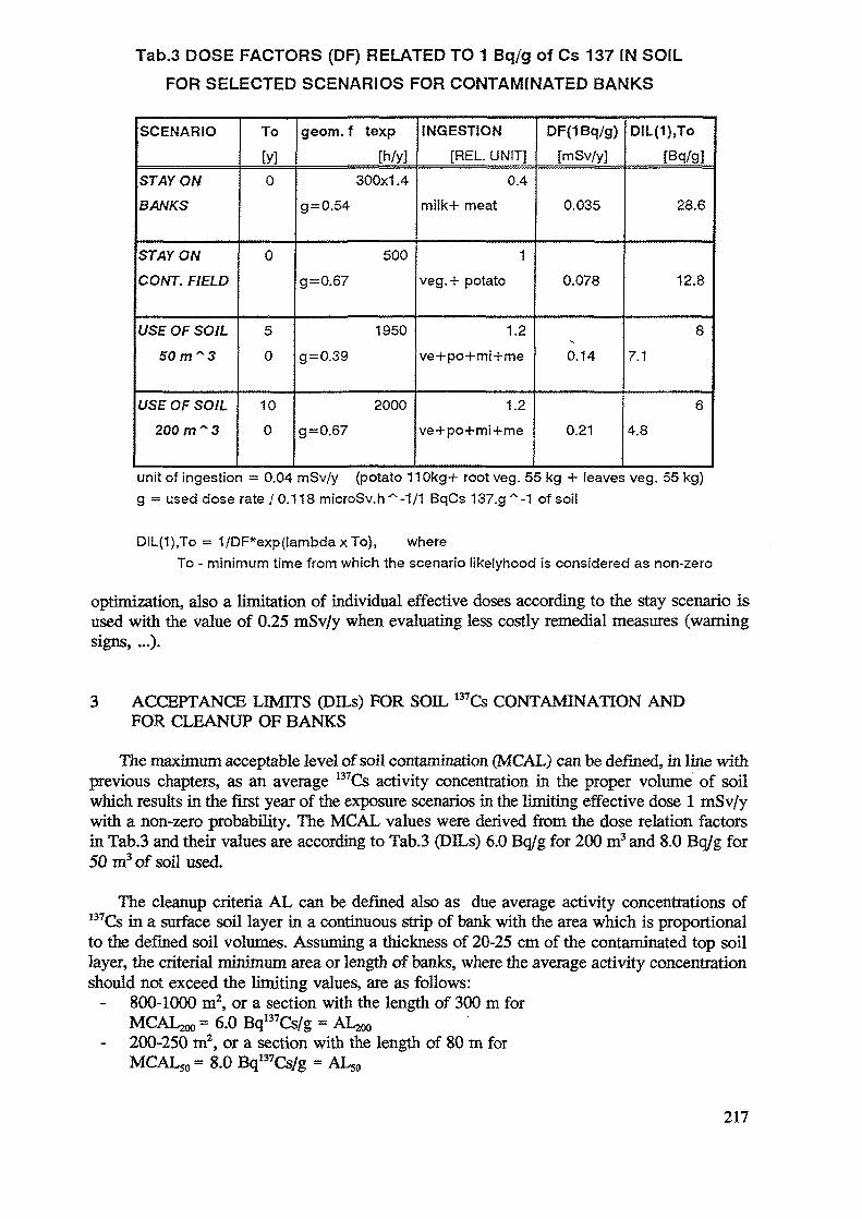
Tab.3 DOSE FACTORS (DF) RELATED TO 1 Bq/g of Cs 137 IN SOILFOR SELECTED SCENARIOS FOR CONTAMINATED BANKS
SCENARIO
STAY ON
BANKS
STAY ON
COWT. FIELD
USE OF SOIL
USE OF SOIL
200 m~3
To
[y]0
0
5
0
10
0
geom. f texp[h/y]
300x1.4
g=0.54
500
g=0.67
1950
g=0.39
2000
g=0.67
INGESTION[REL. UNIT]
0.4mi!k+ meat
1
veg.+ potato
1.2
ve+po+mi+me
1.2
ve+po+mi+me
DF(1Bq/g)[mSv/y]
0.035
0.078
0.14
0.21
DIL(1),To
[Bq/g]
28.6
12.8
8
7.1
6
4.8
unit of ingestion = 0.04 mSv/y (potato 110kg+ root veg. 55 kg + leaves veg. 55 kg)g = used dose rate / 0.118 microSv.h^-1/1 BqCs 137.g^-1 of soil
DIL(1) Jo = 1 /DF*exp (lambda x To), whereTo - minimum time from which the scenario likelyhood is considered as non-zero
optimization, also a limitation of individual effective doses according to the stay scenario isused with the value of 0.25 mSv/y when evaluating less costly remedial measures (warningsigns,...).
3 ACCEPTANCE LIMITS (DILs) FOR SOIL 137Cs CONTAMINATION ANDFOR CLEANUP OF BANKS
The maximum acceptable level of soil contamination (MCAL) can be defined, in line withprevious chapters, as an average 137Cs activity concentration in the proper volume of soilwhich results in the first year of the exposure scenarios in the limiting effective dose 1 mSv/ywith a non-zero probability. The MCAL values were derived from the dose relation factorsin Tab.3 and their values are according to Tab.3 (DILs) 6.0 Bq/g for 200 m3 and 8.0 Bq/g for50 m3 of soil used.
The cleanup criteria AL can be defined also as due average activity concentrations of137Cs in a surface soil layer in a continuous strip of bank with the area which is proportionalto the defined soil volumes. Assuming a thickness of 20-25 cm of the contaminated top soillayer, the criteria! minimum area or length of banks, where the average activity concentrationshould not exceed the limiting values, are as follows:
- 800-1000 m2, or a section with the length of 300 m forMCAL™ = 6.0 Bq137Cs/g = A!™,200-250 m2, or a section with the length of 80 m forMCAL50 = 8.0 Bq137Cs/g = ALSO
217
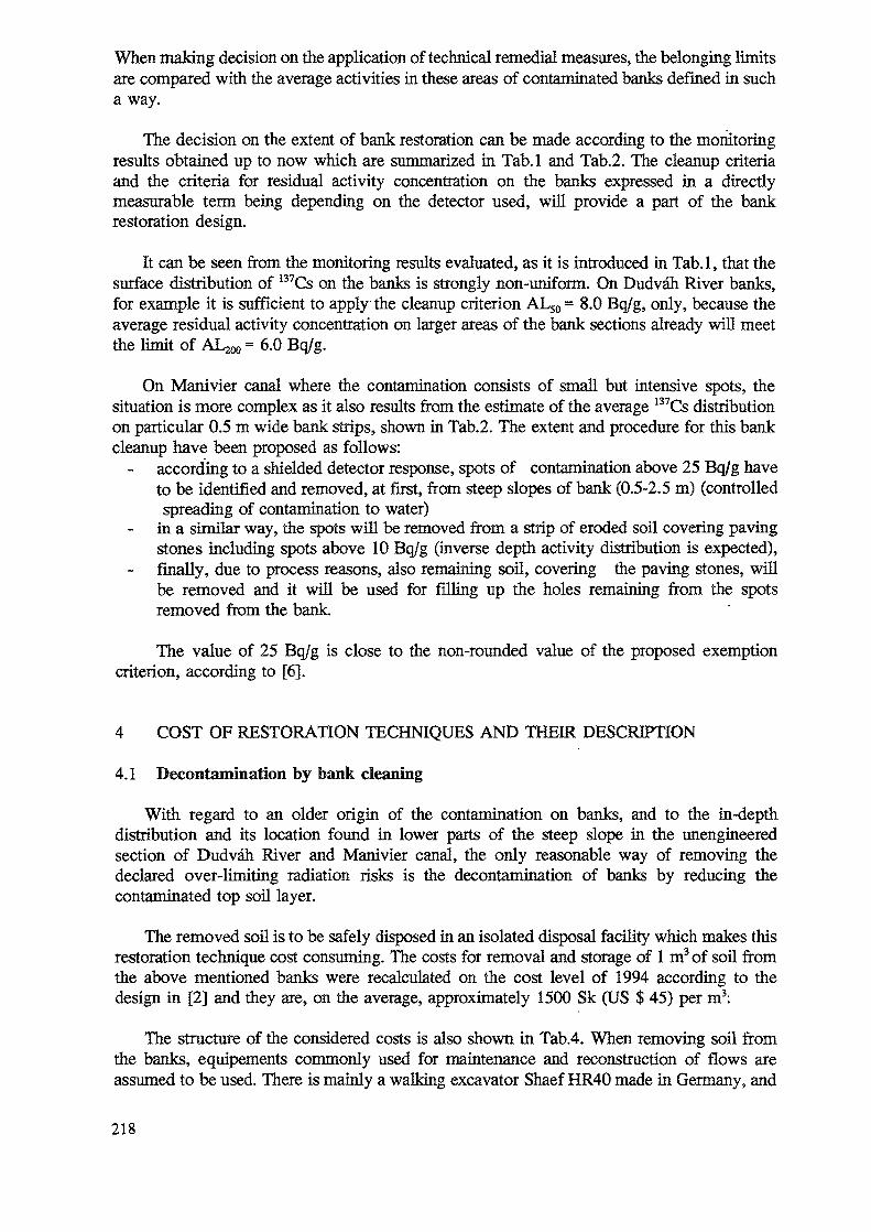
When making decision on the application of technical remedial measures, the belonging limitsare compared with the average activities in these areas of contaminated banks defined in sucha way.
The decision on the extent of bank restoration can be made according to the monitoringresults obtained up to now which are summarized hi Tab.l and Tab.2. The cleanup criteriaand the criteria for residual activity concentration on the banks expressed in a directlymeasurable term being depending on the detector used, will provide a part of the bankrestoration design.
It can be seen from the monitoring results evaluated, as it is introduced in Tab.l, that thesurface distribution of 137Cs on the banks is strongly non-uniform. On Dudvah River banks,for example it is sufficient to apply the cleanup criterion AL50 = 8.0 Bq/g, only, because theaverage residual activity concentration on larger areas of the bank sections already will meetthe limit of AL^ = 6.0 Bq/g.
On Manivier canal where the contamination consists of small but intensive spots, thesituation is more complex as it also results from the estimate of the average 137Cs distributionon particular 0.5 m wide bank strips, shown in Tab.2. The extent and procedure for this bankcleanup have been proposed as follows:
according to a shielded detector response, spots of contamination above 25 Bq/g haveto be identified and removed, at first, from steep slopes of bank (0.5-2.5 m) (controlledspreading of contamination to water)
in a similar way, the spots will be removed from a strip of eroded soil covering pavingstones including spots above 10 Bq/g (inverse depth activity distribution is expected),finally, due to process reasons, also remaining soil, covering the paving stones, willbe removed and it will be used for filling up the holes remaining from the spotsremoved from the bank
The value of 25 Bq/g is close to the non-rounded value of the proposed exemptioncriterion, according to [6].
4 COST OF RESTORATION TECHNIQUES AND THEIR DESCRIPTION
4.1 Decontamination by bank cleaning
With regard to an older origin of the contamination on banks, and to the in-depthdistribution and its location found in lower parts of the steep slope in the unengineeredsection of Dudvah River and Manivier canal, the only reasonable way of removing thedeclared over-limiting radiation risks is the decontamination of banks by reducing thecontaminated top soil layer.
The removed soil is to be safely disposed in an isolated disposal facility which makes thisrestoration technique cost consuming. The costs for removal and storage of 1 m3 of soil fromthe above mentioned banks were recalculated on the cost level of 1994 according to thedesign in [2] and they are, on the average, approximately 1500 Sk (US $ 45) per m3:
The structure of the considered costs is also shown in Tab.4. When removing soil fromthe banks, equipements commonly used for maintenance and reconstruction of flows areassumed to be used. There is mainly a walking excavator Shaef HR40 made in Germany, and
218
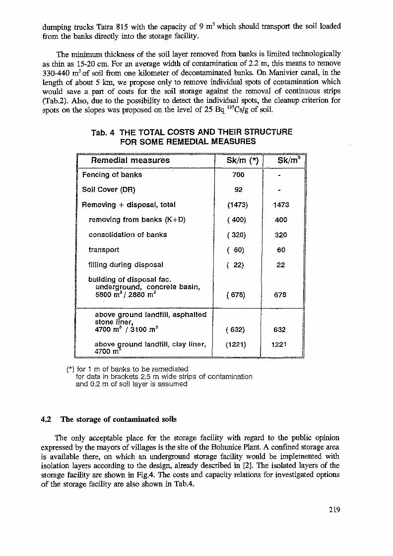
dumping trucks Tatra 815 with the capacity of 9 m3 which should transport the soil loadedfrom the banks directly into the storage facility.
The minimum thickness of the soil layer removed from banks is limited technologicallyas thin as 15-20 cm. For an average width of contamination of 2.2 m, this means to remove330-440 m3 of soil from one kilometer of decontaminated banks. On Manivier canal, in thelength of about 5 km, we propose only to remove individual spots of contamination whichwould save a part of costs for the soil storage against the removal of continuous strips(Tab.2). Also, due to the possibility to detect the individual spots, the cleanup criterion forspots on the slopes was proposed on the level of 25 Bq I37Cs/g of soil.
Tab. 4 THE TOTAL COSTS AND THEIR STRUCTUREFOR SOME REMEDIAL MEASURES
Remedial measuresFencing of banks
Soil Cover (DR)
Removing + disposal, total
removing from banks (K+D)
consolidation of banks
transport
fining during disposal
building of disposal fac.underground, concrete basin,5800m3/ 2880 m2
above ground landfill, asphaltedstone finer,4700 m3 / 3100 m2
above ground landfill, clay liner,4700 m"5
Sk/m (*)700
92
(1473)
(400)
(320)
( 60)
( 22)
( 678)
(632)
(1221)
Sk/m3
-
-
1473
400
320
60
22
678
632
1221
{*) for 1 m of banks to be remediatedfor data in brackets 2.5 m wide strips of contaminationand 0.2 m of soil layer is assumed
4.2 The storage of contaminated soils
The only acceptable place for the storage facility with regard to the public opinionexpressed by the mayors of villages is the site of the Bohunice Plant. A confined storage areais available there, on which an underground storage facility would be implemented withisolation layers according to the design, already described in [2]. The isolated layers of thestorage facility are shown in Fig.4. The costs and capacity rektions for investigated optionsof the storage facility are also shown in Tab.4.
219
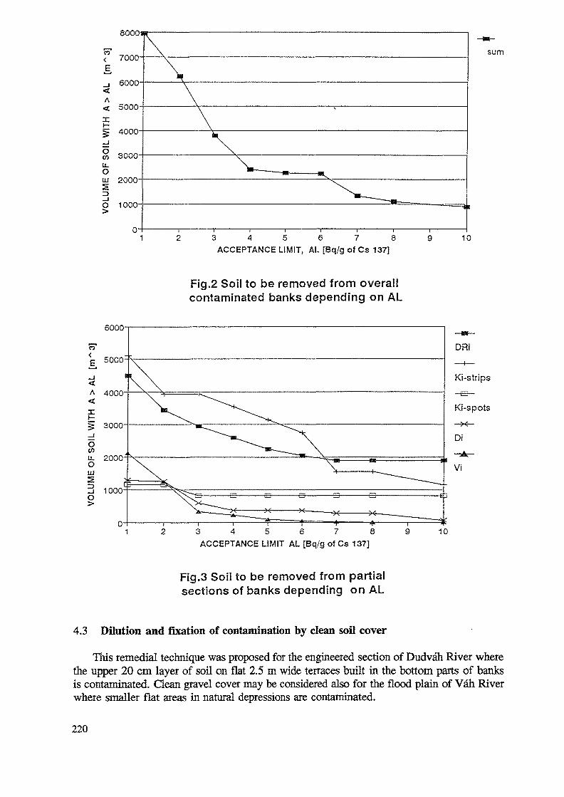
a:
ov>u_OUJ5O
8000
7000-
6000-
5000-
4000'
3000
2000-
1000-
\
sum
3 4 5 6 7 8ACCEPTANCE LIMIT, AL [Bq/g of Cs 137]
10
Fig.2 Soil to be removed from overallcontaminated banks depending on AL
6000
6 7 8
ACCEPTANCE LIMIT AL [Bq/g of Cs 137]10
Fig.3 Soil to be removed from partialsections of banks depending on AL
4.3 Dilution and fixation of contamination by clean soil cover
This remedial technique was proposed for the engineered section of Dudvah River wherethe upper 20 cm layer of soil on flat 2.5 m wide terraces built in the bottom parts of banksis contaminated. Clean gravel cover may be considered also for the flood plain of Vah Riverwhere smaller flat areas in natural depressions are contaminated.
220
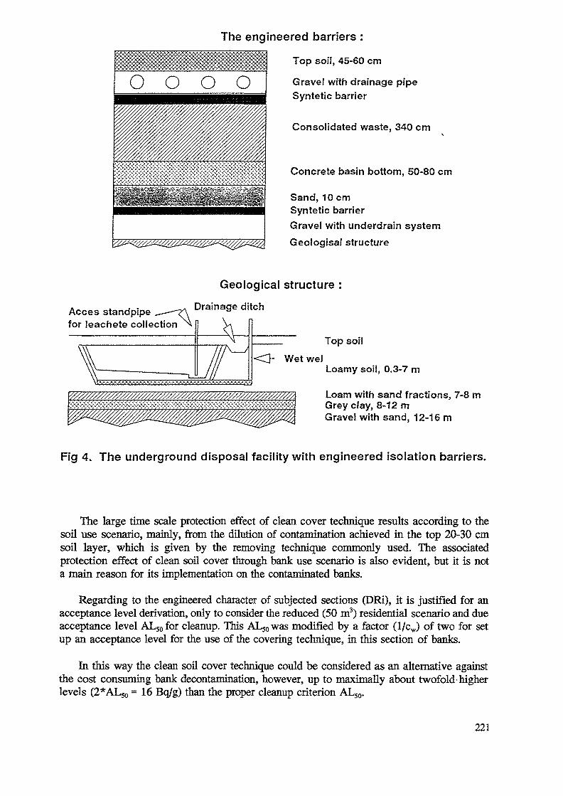
The engineered barriers :
Top soil, 45-60 cm
o o o o Gravel with drainage pipeSyntetic barrier
Consolidated waste, 340 cm
Concrete basin bottom, 50-80 cm
Sand, 10 cmSyntetic barrierGravel with underdrain systemGeologisal structure
Acces standpipefor leachete collection
Geological structure :
Drainage ditch
<3- Wet we!
Top soil
Loamy soil, 0.3-7 m
Loam with sand fractions, 7-8 mGrey clay, 8-12 mGravel with sand, 12-16 m
Fig 4. The underground disposal facility with engineered isolation barriers.
The large time scale protection effect of clean cover technique results according to thesoil use scenario, mainly, from the dilution of contamination achieved in the top 20-30 cmsoil layer, which is given by the removing technique commonly used. The associatedprotection effect of clean soil cover through bank use scenario is also evident, but it is nota main reason for its implementation on the contaminated banks.
Regarding to the engineered character of subjected sections (DRi), it is justified for anacceptance level derivation, only to consider the reduced (50 m3) residential scenario and dueacceptance level ALsofor cleanup. This AL50was modified by a factor (l/cw) of two for setup an acceptance level for the use of the covering technique, in this section of banks.
In this way the clean soil cover technique could be considered as an alternative againstthe cost consuming bank decontamination, however, up to maximally about twofold higherlevels (2*AL5o =16 Bq/g) than the proper cleanup criterion ALS0.
221
On these engineered sections, only, the DR3 one does not comply the cleanup criteria foraverage concentrations ( 9.6 Bq of 137Cs/g versus AL200=6.0 Bq/g - Tab.3) . Also, accordingto the obtained monitoring results [1], even on the smaller parts of these sections the 137Csconcentration does not exceed the mentioned 16 Bq/g. Consequently, the soil removing fromthis section is not necessary.
The cost for the implementation of this technique is approximately 10 times lower incomparison with the alternative decontamination by soil removing technique (Tab.4).
5 THE SCOPE OF THE CONTAMINATED BANKS RESTORATION
According to the criteria developed, it is necessary to subject to the restorationapproximately 11 000 m2 of contaminated area on the Dudvah River banks (Tab.l.) The mostof this area are in the engineered section DR3, where clean soil cover is sufficient to beapplied on an area of approximately 9 500 m2 as it was described earlier.
In the contaminated sections of Vah Rivefs flood plain, the activity concentrations founddo not exceed the defined cleanup criteria, even though all specifications of this place werenot taken into account up to now (contamination of gravels and underground water). However,30-50 cm clean gravel cover on smaller areas is considered, only, in these places as amaximum.
The extent of the entire contamination of banks is also shown in Fig.3 in the graph ofassumed volume of contaminated soil to be removed from the partial bank sections dependingon a variable cleanup limit AL. It can be seen from this figure that this volume of soilstrongly depends on the value of cleanup limit AL.
From Fig.2 with a like graph as in Fig.3, but for the summary of the sections, it is seenthat in case of the proposed cleanup criteria (6 and 8 Bq/g) about 1 100 m3 of soil is to beremoved from the Manivier canal and unengineered Dudvah River's contaminated banksalready taking into account application of the cover technique in the engineered part of theDudvali River.
6 CONCLUSIONS
In the subjected field, clear legislation absents in the Slovak Republic. To considerplanning for restoration of the contaminated banks near Bohunice NPP, new principles for theevaluation was developed in close cooperation with the national hygiene authorities. Theprinciples as well as the resulting evaluation and proposal of the justified extent of banksrestoration are being now under final authorisation.
The ICRP dose limitation system for recovery of contaminated site was used as a basisfor these purposes. The value of ImSv/y was set up as a basic maximum acceptable doselimit, exceeding of which only justifies implementation of a cost consuming restorationtechniques. Cleanup and contamination acceptance criteria was developed as 137Csconcentration in soil (8.0 or 6.0 Bq/g depending on the size of contaminated area/volume) onthe basis of authorised radiation risk scenarios for potential use of the contaminated soilaround a residential house.
222
The reevaluated extent of the banks restoration project would include removing and safeburial on the Bohunice NPP site of approximately 1100 m3 of contaminated soil from, and theoverlaying by clean 10-15 cm soil cover on about 10 000 m2of contaminated flat area of thebanks.
During the restoration of banks commonly available equipment from water-service industryis planned to be used. The total cost for the proposed bank restoration project which wouldbe implemented in years 1995/96 can be estimated by the sum of about US $ 100 000.
REFERENCES
[1] SLAVIK, O., MORAVEK, L, Identification and Radiological Characterization ofContaminated Sites in the Slovak Republic, Rep. I. IAEA Workshop "Restoration ofContaminated Sites in Central in Eastern Europe", 4.-8 October 1993, Budapest
[2] SLAVIK, O., MORAVEK, J., Planning for Environmental Restoration in the SlovakRepublic, Rep. H IAEA Workshop on "Restoration of Contaminated Sites in Centralin Eastern Europe", 11-15 April 1994, Piesfany
[3] OZTUNALI, (XL, and all, Data Base for Radioactive Waste Management,NUREG/CR-1759, vol.3
[4] COCHER, D.C, Dose rate conversion factors for external exposure to photon emittersin soil, Health Phys. 48 No 2 (1985) 193-205
[5] INTERNATIONAL ATOMIC ENERGY AGENCY, Handbook of parameter values forthe prediction of radionuclide transfer in temperate environment, Vienna, 1993
[6] COMMISSION OF EUROPEAN COMMUNITIES, Radiation protection 65,Doc. XI-028/93
223
TECHNOLOGIES FOR AND IMPLEMENTATION OFENVIRONMENTAL RESTORATION PROJECTS IN SLOVENIA
MJ. KRIZMANJoseph Stefan Institute
Z. LOGARRudnik Zirovsky, Gorenja
Slovenia
Abstract
Not all environmental restoration technologies have been tested and evaluated in Slovenia andimplementation of environmental restoration projects will not start before 1995. Information ispresented in this paper on Slovenia's state-of-the-art in this field. The aim is to present shortly thestate, design and implementation of rehabilitation works. Particular emphasis is given to the followingaspects: regulations, planning, research, investigations and implementation.
1. INTRODUCTION
1.1. Identification and radiological characterization of contaminated sites in Slovenia.(Summary from the 1st workshop contribution)
There are no sites accidentally contaminated with radioactivity in Slovenia in the verbal meaningof the title.Compared to the large extent of contaminated sites in other countries, this problem arises inSlovenia only on a small scale and at low level.
- The former uranium mine Zirovski vrh with its mining and milling facilities and waste depositsis at the moment a unique case in urgent need of restoration.
Beside the U-mine, numerous local disposal sites with technologically enhanced naturalradioactivity, with moderately low level U and Th content also need restoration. Theseare deposits in some mining districts (mercury, coal and coal-ash), large coal-ashdeposits near thermal power plants, and large deposits near various ore processingfactories (ilmenite, bauxite, phosphates)
Out of the scope of this paper but worthy of mention: the central state storage for lowlevel radioactive sources and wastes, mainly from medical and industrial use (Podgorica);an isolated storage place with accidentally contaminated material due to medical use ofradium needles (Zavratec); the temporary low and medium radioactive waste storagefacility at the Krsko nuclear power plant;The planning of a new low and medium radioactivity waste storage facility is in progress.
The main attention related to contaminated sites in Slovenia is focused on the restorationactivities at the former uranium mining and milling plant at Zirovski Vrh. Relatively low gradeore was excavated and treated (less than 0.1 % U3O8) there in the period 1985-1990. Radioactive
225
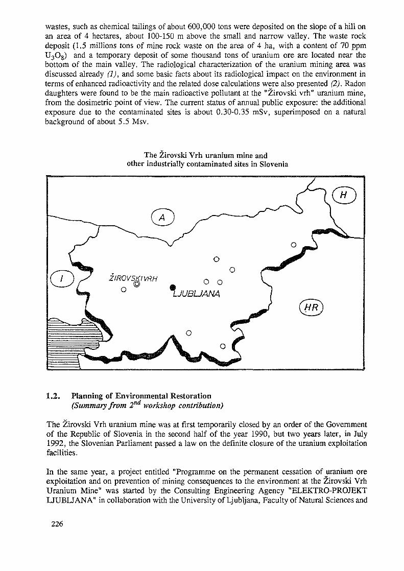
wastes, such as chemical tailings of about 600,000 tons were deposited on the slope of a hill onan area of 4 hectares, about 100-150 m above the small and narrow valley. The waste rockdeposit (1.5 millions tons of mine rock waste on the area of 4 ha, with a content of 70 ppmU3O8) and a temporary deposit of some thousand tons of uranium ore are located near thebottom of the main valley. The radiological characterization of the uranium mining area wasdiscussed already (1), and some basic facts about its radiological impact on the environment interms of enhanced radioactivity and the related dose calculations were also presented (2). Radondaughters were found to be the main radioactive pollutant at the "Zirovski vrh" uranium mine,from the dosimetric point of view. The current status of annual public exposure: the additionalexposure due to the contaminated sites is about 0.30-0.35 mSv, superimposed on a naturalbackground of about 5.5 Msv.
The Zirovski Vrh uranium mine andother industrially contaminated sites in Slovenia
1.2. Planning of Environmental Restoration(Summary from 2nd workshop contribution)
The Zirovski Vrh uranium mine was at first temporarily closed by an order of the Governmentof the Republic of Slovenia in the second half of the year 1990, but two years later, in July1992, the Slovenian Parliament passed a law on the definite closure of the uranium exploitationfacilities.
In the same year, a project entitled "Programme on the permanent cessation of uranium oreexploitation and on prevention of mining consequences to the environment at the Zirovski VrhUranium Mine" was started by the Consulting Engineering Agency "ELEKTRO-PROJEKTLJUBLJANA" in collaboration with the University of Ljubljana, Faculty of Natural Sciences and
226
Technology (3). The Programme (see paragraph 2.2. later) covers all aspects ofdecommissioning of the mining and milling facilities and was accepted by the Government inApril 1994. Its aim was to present the scope of the rehabilitation work, the time schedule, thenecessary investigations, and costs and funds needed to complete a restoration.
In this period some pilot studies and other investigations (modelling, field studies) related torestoration of the tailings pile and waste rock disposal were also made (see Piestany contribution(2) and further paragraph 2.3.). It also became obvious that there was a need for a relevantregulatory framework, not yet existing for cases for restoration of contaminated sites (seePiestany contribution (2) and paragraph 2.1.).
2. TECHNOLOGIES FOR AND IMPLEMENTATION OF ENVIRONMENTALRESTORATION PROJECTS IN SLOVENIA
There will be no clear distinction in this paper between the subjects of the last workshop (chapter1.2. -PER) and the subject of this chapter (2. - TIER) and some overlapping will occur. Namely,not all technologies have yet been elaborated and the implementation of environmentalrestoration projects will start not before next year. We shall present here information on nationalstate-of-the art activities in the field. The aim of this chapter is to present shortly the status,design and implementation of rehabilitation works.
The further discussion in this paper is concerned with the following items:regulations, projects, investigations and research, and implementation.
2.1. REGULATIONS
A regulatory framework concerning environmental aspects of restoration has been in preparationsince 1993, to set authorized limits for emissions from tailings and wastes and for residualenvironmental radioactivity, including all categories of contaminated sites, including radioactivitydeposited from non-uranium related practices.
Standards for environmental protection against ionizing radiations (a draft version)
When preparing the standards for environmental protection against ionizing radiations (4)account was taken of the specific situation: i.e. due to the low level of contamination inSlovenia, more severe limitations (relative to other European countries) and stricter requirementsfor future waste disposal for non-nuclear radioactive wastes with natural radioactivity, aredemanded on account of the relatively high population density and limited area of the country(territory).
Standards are provisional and are nowadays still in a draft version. Standards cover four items,including nuclear facilities', facilities and activities, where unsealed radioactive sources are used;permanent storage of low and medium levels of radioactive waste and finally, waste disposal(mining and industrial tailings) from processed raw ores with enhanced natural radioactivity -(U and Th ore, coal-ash, other residues from industrial processing plants).
227
General limitations
Annual dose limits for public exposure for the reference group are the following:
(1) 0.10 mSv for the effective dose or whole-body dose(2) 0.15 mSv for the organs gonads, uterus, red bone marrow(3) 0.60 mSv for skin and bone surface tissue(4) 0.30 mSv for other organs and tissues, excluding those in (2) and (3).
If there is more than one object (source) that contributes the to exposure of the reference group,then the above limitations are applied to the sum of exposures caused by these objects.
Special requirements
Future owners and users of each new open disposal site should have an operating and a closureplan, that should be submitted to the competent governmental authority to acquire a radiologicallicense for the beginning of operation. This procedure is obligatory for all owners of- mining and milling tailings related to uranium exploitation,- to other mining and industrial tailings (with enhanced radioactivity) with a deposit area larger
than 1 ha or with a total volume greater than 20,000 m3,- to coal-ash deposits with a total area larger than 1 ha and a total volume greater than 20,000
m3.
The expression "total area" means the sum of areas of all locally separated disposal sites of thesame owner and user and all tailings of the same kind of material.
All users of already existing disposal sites with the above characteristics should performradiological measurements within a period of 12 months. After that all tailings should beclassified according to these regulations. Radiological measurements should cover externalgamma dose rate, average specific activities of natural and artificial radionuclides, measurementsof the radioactivity of emissions and surveillance measurements of inputs (imissions). Duringthe operation of a disposal site, tailings should be determined periodically; in already depositedmaterial control of radioactivity should be measured in the following layers: (0-0.3 m, 0.3-0.6m, from 0.6 m in steps of 1.0 m to the natural ground level).
Criteria for the classification of tailings concerning deposited material with enhanced contentsof radionuclides from the uranium and thorium decay chain were established. Intervals of classeswere defined according to the available data on known industrial disposal sites in the country.
The last group (IV) is further considered in more detail, because it is concerned in uraniummining and milling wastes.
IV. class of tailings (related to uranium production)
The uranium mine and mill disposal sites are under systematic control in the regulated(controlled) area and in the nearby surroundings. This control comprises external radiation,water and pathways, the food-chain transfer. Removal and use of deposited material is notallowed without the special permission of a competent authority.
228
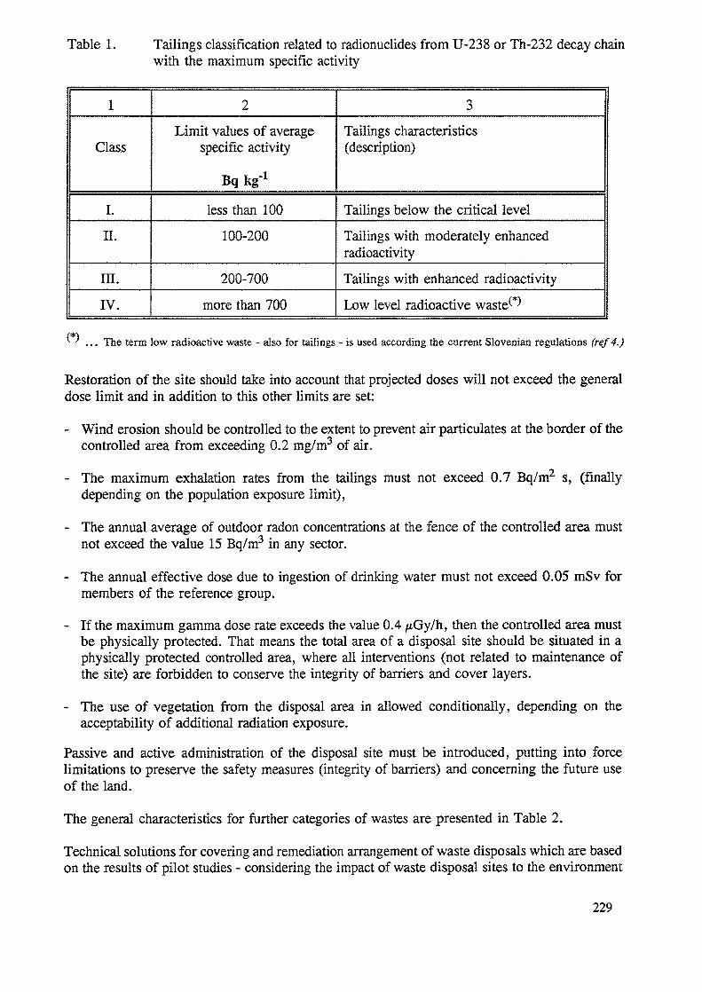
Table 1. Tailings classification related to radionuclides from U-238 or Th-232 decay chainwith the maximum specific activity
1
Class
I.II.
m.IV.
2
Limit values of averagespecific activity
Bq kg"1
less than 100100-200
200-700more than 700
3Tailings characteristics(description)
Tailings below the critical levelTailings with moderately enhancedradioactivity
Tailings with enhanced radioactivity
Low level radioactive waste^
(#)^ ' ... The term low radioactive waste - also for tailings - is used according the current Slovenian regulations (ref4.)
Restoration of the site should take into account that projected doses will not exceed the generaldose limit and in addition to this other limits are set:
- Wind erosion should be controlled to the extent to prevent air particulates at the border of thecontrolled area from exceeding 0.2 mg/m3 of air.
- The maximum exhalation rates from the tailings must not exceed 0.7 Bq/m2 s, (finallydepending on the population exposure limit),
- The annual average of outdoor radon concentrations at the fence of the controlled area mustnot exceed the value 15 Bq/m3 in any sector.
- The annual effective dose due to ingestion of drinking water must not exceed 0.05 mSv formembers of the reference group.
- If the maximum gamma dose rate exceeds the value 0.4 /iGy/h, then the controlled area mustbe physically protected. That means the total area of a disposal site should be situated in aphysically protected controlled area, where all interventions (not related to maintenance ofthe site) are forbidden to conserve the integrity of barriers and cover layers.
- The use of vegetation from the disposal area in allowed conditionally, depending on theacceptability of additional radiation exposure.
Passive and active administration of the disposal site must be introduced, putting into forcelimitations to preserve the safety measures (integrity of barriers) and concerning the future useof the land.
The general characteristics for further categories of wastes are presented in Table 2.
Technical solutions for covering and remediation arrangement of waste disposals which are basedon the results of pilot studies - considering the impact of waste disposal sites to the environment
229
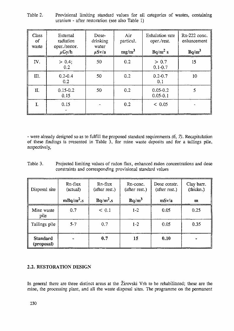
Table 2. Provisional limiting standard values for all categories of wastes, containinguranium - after restoration (see also Table 1)
Classof
waste
IV.
III.
II.
I.
Externalradiation
oper./restor./tGy/h
> 0.4;0.2
0.2-0.40.2
0.15-0.20.15
0.15
Dose-drinking
waterAiSv/a
50
50
50
-
Airparticul.
mg/m3
0.2
0.2
0.2
0.2
Exhalation rateoper./rest.
Bq/m2 s
> 0.70.1-0.7
0.2-0.70.1
0.05-0.20.05-0.1
< 0.05
Rn-222 cone.enhancement
Bq/m3
15
10
5
-
- were already designed so as to fulfill the proposed standard requirements (6, 7). Recapitulationof these findings is presented in Table 3, for mine waste deposits and for a tailings pile,respectively.
Table 3. Projected limiting values of radon flux, enhanced radon concentrations and doseconstraints and corresponding provisional standard values
Disposal site
Mine wastepile
Tailings pile
Standard(proposal)
Rn-flux(actual)
mBq/m2.s
0.7
5-7
«.
Rn-flux(after rest.)
Bq/ra2.s
< 0.1
0.7
0.7
Rn-conc.(after rest.)
Bq/m3
1-2
1-2
15
Dose constr.(after rest.)
rnSv/a
0.05
0.05
0.10
Clay barr.(thickn.)
m
0.25
0.35
•
2.2. RESTORATION DESIGN
In general there are three distinct areas at the Zirovski Vrh to be rehabilitated; these are themine, the processing plant, and all the waste disposal sites. The programme on the permanent
230
cessation of uranium ore exploitation and on prevention of mining consequences to theenvironment at Zirovski Vrh Uranium Mine (3) consists of the following sub-projects:
- project for permanent closure of the uranium ore mine exploitation facilities,
- project for cessation of the uranium ore processing plant with permanent environmentalprotection against the consequences of uranium concentrate production,
- project for restoration of the waste disposal sites: mine waste piles and mill tailings pile,- permanent environmental protection against the consequences of disposal and storage with
long-term environmental monitoring after restoration of the site
The time schedule, manpower and costs of closing down are also important parts of theprogramme. Roughly 50-70 million ECU are provided for the restoration of the site within aperiod of 5-7 years (provisionally by 2002).
Main attention at present is focused on restoration of the tailings pile; a major problem isslippage of the slope (7 millions tonnes) with dry tailings on the top (0.6 million tonnes)downwards to the valley at a velocity of 0.3 m per year. Three alternatives were elaborated tosolve the problem of mill tailings slippage, each of them is dependent on the technical solutionchosen for the mine closure. No decision has been made yet.
The restoration of sites should actually start at the beginning of 1995.
2.3. INVESTIGATIONS
The following investigations have been performed or are still going on in connection withrehabilitation of the affected area:
Radiological research and measurements (ref. 6,7,8):
- Gamma dose rates (on mill site and inside buildings, in mine facilities, at all waste disposalsites and in their surroundings, in the vicinity of the exploitation area, on industrial roadsused during operation of the mine etc.),
- Radon-222 exhalation rate (on mill tailings, on mine waste piles, transmission of radonthrough provisional clay and soil layers (radon barriers),
- Alpha and beta surface contamination (mill site, mill buildings, equipment etc.),- Indoor radon-222 concentrations (in process buildings, in mine facilities),- Exposure of public (dose to the critical groups),- Radioactive pollutants in surface waterflows,
Hydrogeological research work (ref. 9) :
- hydrology and hydro-geology of the mine area,- reduction of the degree of pollution of mine water,- investigation of underground waters (area of the mill site, mill tailing site, and mine waste
disposal site), and of the Brebovscica stream underground aquifer,- study of the biological and chemical quality of surface waterflows,
231
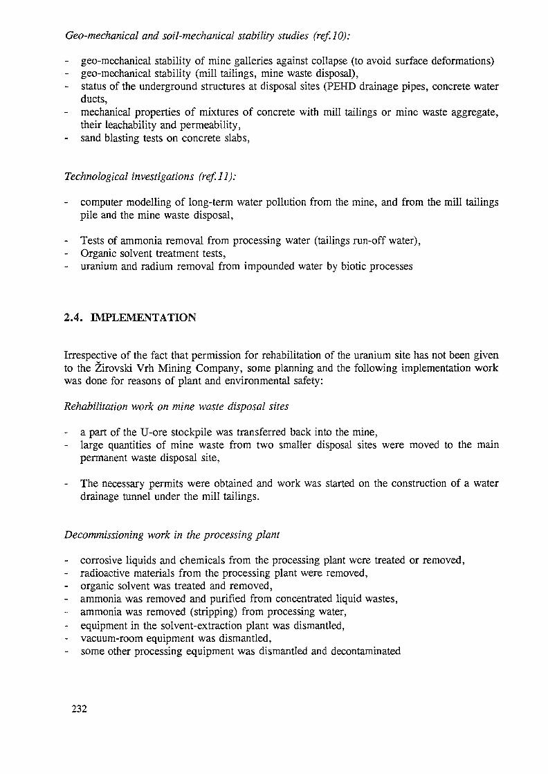
Geo-mechanical and soil-mechanical stability studies (ref.10):
- geo-mechanical stability of mine galleries against collapse (to avoid surface deformations)- geo-mechanical stability (mill tailings, mine waste disposal),- status of the underground structures at disposal sites (PEHD drainage pipes, concrete water
ducts,- mechanical properties of mixtures of concrete with mill tailings or mine waste aggregate,
their teachability and permeability,- sand blasting tests on concrete slabs,
Technological investigations (ref.ll):
- computer modelling of long-term water pollution from the mine, and from the mill tailingspile and the mine waste disposal,
- Tests of ammonia removal from processing water (tailings run-off water),- Organic solvent treatment tests,- uranium and radium removal from impounded water by biotic processes
2.4. IMPLEMENTATION
Irrespective of the fact that permission for rehabilitation of the uranium site has not been givento the Zirovski Vrh Mining Company, some planning and the following implementation workwas done for reasons of plant and environmental safety:
Rehabilitation work on mine waste disposal sites
- a part of the U-ore stockpile was transferred back into the mine,- large quantities of mine waste from two smaller disposal sites were moved to the main
permanent waste disposal site,
- The necessary permits were obtained and work was started on the construction of a waterdrainage tunnel under the mill tailings.
Decommissioning work in the processing plant
- corrosive liquids and chemicals from the processing plant were treated or removed,- radioactive materials from the processing plant were removed,- organic solvent was treated and removed,- ammonia was removed and purified from concentrated liquid wastes,- ammonia was removed (stripping) from processing water,- equipment in the solvent-extraction plant was dismantled,- vacuum-room equipment was dismantled,- some other processing equipment was dismantled and decontaminated
232
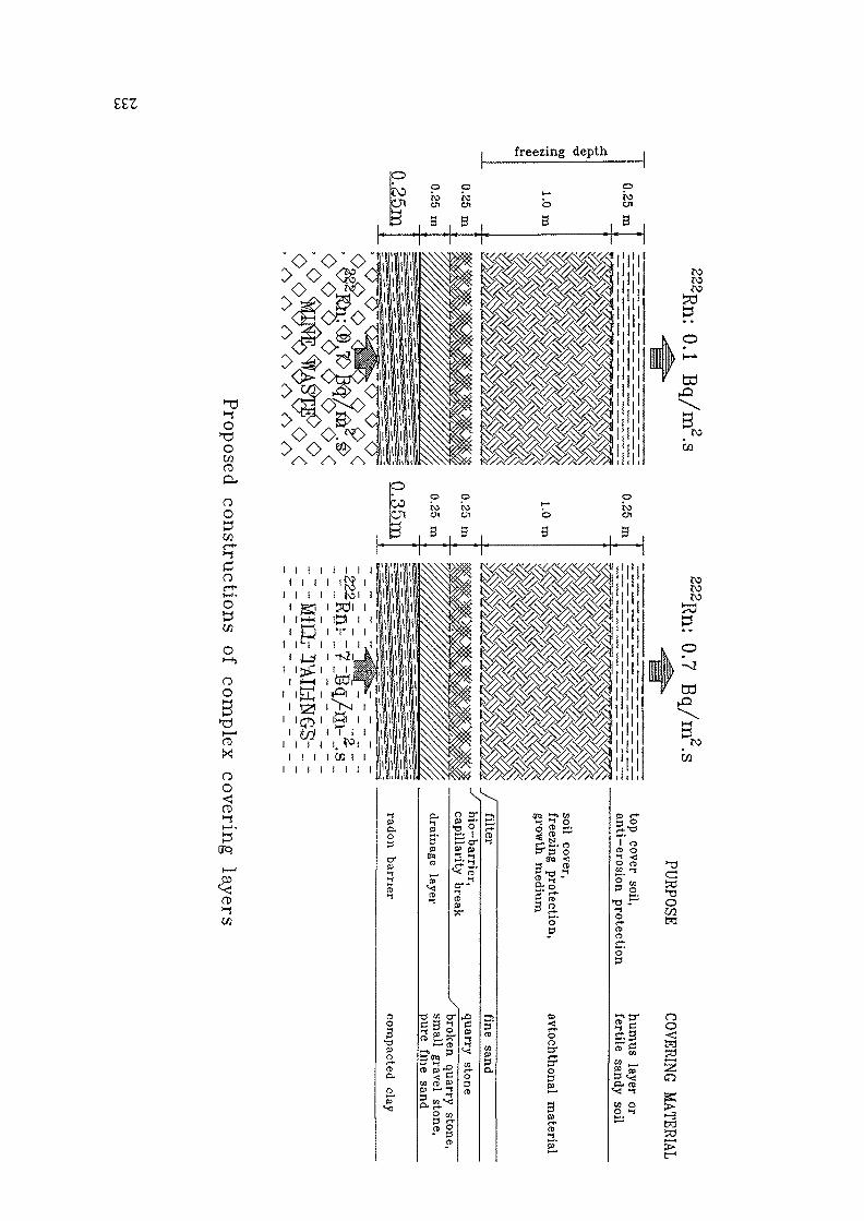
££Z
oCfl
freezing depthpro p
k>pro
O'O'O
roen
——— : ——— p.1 I I
oo
or*->— *•OSCfl
O»-b
OO
X
oo<JCD
CJ1 en
3 i B f
en o
." I- 3
en
1 3. .. ... .
I I I I I I I II I I )
I I I I I tO I I-gj i 3d
i i i I' ' ' 'I i i i i. ^° i i
i i i i cn i ii i i i i i i i
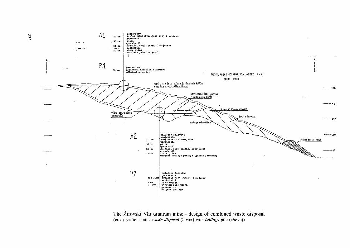
to Al 50
.. SO
50
SO <
El
i«cr*vit«vIconJnl r«kuieiv*eljB>ei Bloj 8 hunugorag«otekscilglto*•gaoteKBCildrenaini sloj (p«eek, locnljenec)
ibitt glin*odlotena jalovina IBM)
tacrnvitevovtohtonl material a humueomodlaieai tMLtQuigJ.
PROFIl. PREKO ODLAGAtlSCA JAZBEC A - A '
MERILO 1:1000koncno stanje po odlaganju dodatnih kolfinmaterials z odlaqaliSca Bofst
hidrometalurska jalwinaiz odlaqalisca Borst
————520
——— 500
50 cm50 04SO cm100cm
3 mcft5-iOcn
odloiena jaloviaageocekstlleloj peek* in lexoljencageoeekBcllglin*geocekscildrenaini sloj (pesek, loraljenecjgeotekotiltbica glinaucrjena podlag« platoja {jamska jalovina)
odloJena jalovinageoteketil.drenaJEni aloj tpes«k, lomXjenec)geotekotilPEKD folijauvaXjan aloj peskageoteketilutrjena podlaga
The Zirovski Vhr uranium mine - design of combined waste disposal(cross section: mine waste disposal (lower) with tailings pile (above))
The decontamination procedures applied at the processing plant site have been shown to meetthe following decommissioning criteria, set by the competent governmental authorities:
- Gamma dose rate - everywhere in decontaminated area < 0,2 juG/h- Alpha surface contamination, equipment and plant surfaces < 4 Bq/100 cm2
- Beta surface contamination, equipment and plant surfaces < 40 Bq/100 cm2
- Indoor radon gas concentrations, at work-places < 250 Bq/m3.
3. CONCLUSIONS
The beginning of restoration work at the Zirovski Vrh uranium mine has been delayed andshifted to 1995. The rehabilitation dynamics will depend on available funds (state budget). Somedecommissioning work has begun already, and the whole restoration of the site should befinished provisionally in 2002. Technical solutions are not completed for all aspects of the work.
In the following years some other restoration plans and activities, not related to the uraniummine, are expected to start in Slovenia.
REFERENCES
(1) Logar Z., Identification and Radiological Characterization of Contaminated Sites inSlovenia, 1st Workshop of IAEA on Environmental Restoration in Central and EasternEurope, Budapest, 4 -8 October 1993
(2) Krizman M. J., Planning on Environmental Restoration in Slovenia, 2nd Workshop of IAEAon Environmental Restoration in Central and Eastern Europe, Piestany, 11-15 April 1994
(3) Bajzelj U., Zabukovec I., Kvaternik K. The programme of permanent cessation of uraniumore exploitation and permanent environmental protection at Zirovski Vrh uranium mine,Report B103/9, Elektroprojekt Ljubljana, Ljubljana, February 1993 (in Slovene)
(4) Miklavzic" U., Krizman M., Technical Grounding for Regulations and Standing Orders ofEnvironmental Protection Law, Standards of Environmental Protection against IonizingRadiations, (Draft), Report for the Ministry for Environmental and Rural Planning, AMESDP-101, Ljubljana, August 1994 (in Slovene)
(5) Regulations on mode of collecting, keeping records, processing, storing, final depositionand discharging of radioactive waste materials into living environment, Federal officialgazette, No. 40/86 (in Slovene)
(6) M.Krizman, P.Stegnar, D.Konda, Testing of covering materials on uranium tailings pileat Borst, and determination of the structure and thickness of covering layer, ITS ReportDP-6431, Ljubljana, March 1992 (in Slovene)
(7) Krizman M., Stegnar P., Konda D., Study of parameters for restoring of mine waste pileat Jazbec (The Zirovski Vrh Uranium mine, Slovenia), Report, US DP-6950, Ljubljana,February 1994 (in Slovene)
235
(8) Rojc J., Likar B., Logar Z., Ionizing Radiation Measurements at the Zirovski Vrh uraniummine, interim reports of the Health and Safety Department of the Zirovski Vrh Mine,(1992-1994), Todraz (in Slovene)
(9) Begus and al., Interim reports on the hydrology of the Zirovski Vrh Mine, (1992-1994),Todraz, (in Slovene)
(10) Somrak D., The "Borst" Mill Tailings Disposal Site - Slippage Restoration, ConsultingEngineering "Elektroprojekt", Ljubljana, 1992 (in Slovene)
(11) Ponikvar and al., Report on Non-radiological, Chemical and Biological Investigation of theon Surface Streams at "Zirovski Vrh" Mine in 1994, Report of Chemical Institute,Ljubljana, October 1994 (in Slovene)
(12) M.Krizman, P.Stegnar, Environmental Radioactivity in the Zirovski Vrh Uranium Mineand the Impact Assessment in 1992, Report, US DP-6750, Ljubljana, May 1993 (inSlovene)
(13) IAEA Technical Reports Series (Draft version), The Decommissioning of Uranium andMilling Facilities and the Closeout of Tailings Impoundments, Vienna, March 1992
(14) Australian Government Department of Home Affairs and Environment, Code of Practiceon Management of Radioactive Wastes from the Mining and Milling of Radioactive Ores,(3rd set Additional Guidelines), Canberra 1983
(15) IAEA Technical Reports Series (Draft version), Measurement and Calculation of RadonReleases from Uranium Mill Tailings, Vienna, July 1991
(16) Health and environmental protection standards for uranium and thorium mill tailings, CFR40, Chapter I - EPA, Part 192, Subpart A, B, D in E, Washington, July 1, 1991
(17) Strahlenschutzgrundsatze fuer die Verwahrung, Nutzung oder Freigabe von kontaminiertenMaterialen, Gebaueden, Flaechen oder Halden aus dem Uranerzbergbau, Empfelunen derStrahlenschutz Kommission mit Erlauterungen, Bonn, April 1992
(18) Strahlenschutzgrundsaetze fuer die Verwahrung und Nutzung von Berghalden,Empfelungen der Strahleschutzkommission, Bonn, Oktober 1991
236
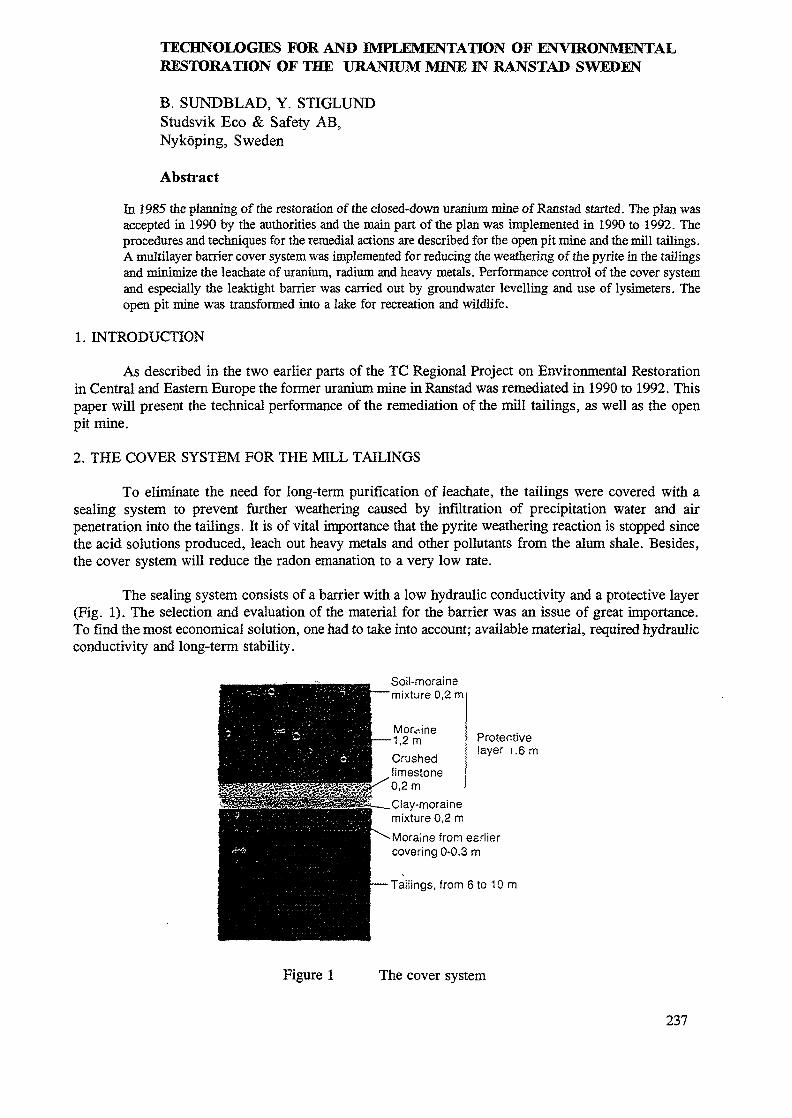
TECHNOLOGIES FOR AND IMPLEMENTATION OF ENVIRONMENTALRESTORATION OF THE URANIUM MINE IN RANSTAD SWEDEN
B. SUNDBLAD, Y. STIGLUNDStudsvik Eco & Safety AB,Nykoping, Sweden
Abstract
In 1985 the planning of the restoration of the closed-down uranium mine of Ranstad started. The plan wasaccepted in 1990 by the authorities and the main part of the plan was implemented in 1990 to 1992. Theprocedures and techniques for the remedial actions are described for the open pit mine and the mill tailings.A multilayer barrier cover system was implemented for reducing the weathering of the pyrite hi the tailingsand minimize the leachate of uranium, radium and heavy metals. Performance control of the cover systemand especially the leaktight barrier was carried out by groundwater levelling and use of lysimeters. Theopen pit mine was transformed into a lake for recreation and wildlife.
1. INTRODUCTION
As described in the two earlier parts of the TC Regional Project on Environmental Restorationin Central and Eastern Europe the former uranium mine in Ranstad was remediated in 1990 to 1992. Thispaper will present the technical performance of the remediation of the mill tailings, as well as the openpit mine.
2. THE COVER SYSTEM FOR THE MILL TAILINGS
To eliminate the need for long-term purification of leachate, the tailings were covered with asealing system to prevent further weathering caused by infiltration of precipitation water and airpenetration into the tailings. It is of vital importance that the pyrite weathering reaction is stopped sincethe acid solutions produced, leach out heavy metals and other pollutants from the alum shale. Besides,the cover system will reduce the radon emanation to a very low rate.
The sealing system consists of a barrier with a low hydraulic conductivity and a protective layer(Fig. 1). The selection and evaluation of the material for the barrier was an issue of great importance.To find the most economical solution, one had to take into account; available material, required hydraulicconductivity and long-term stability.
Protectivelayer i .6 m
Soil-morainemixture 0,2 m
Moa-.ine1,2mCrushedlimestone
Clay-morainemixture 0,2 mMoraine from earliercovering 0-0.3 m
Tailings, from 6 to 10 m
Figure 1 The cover system
237
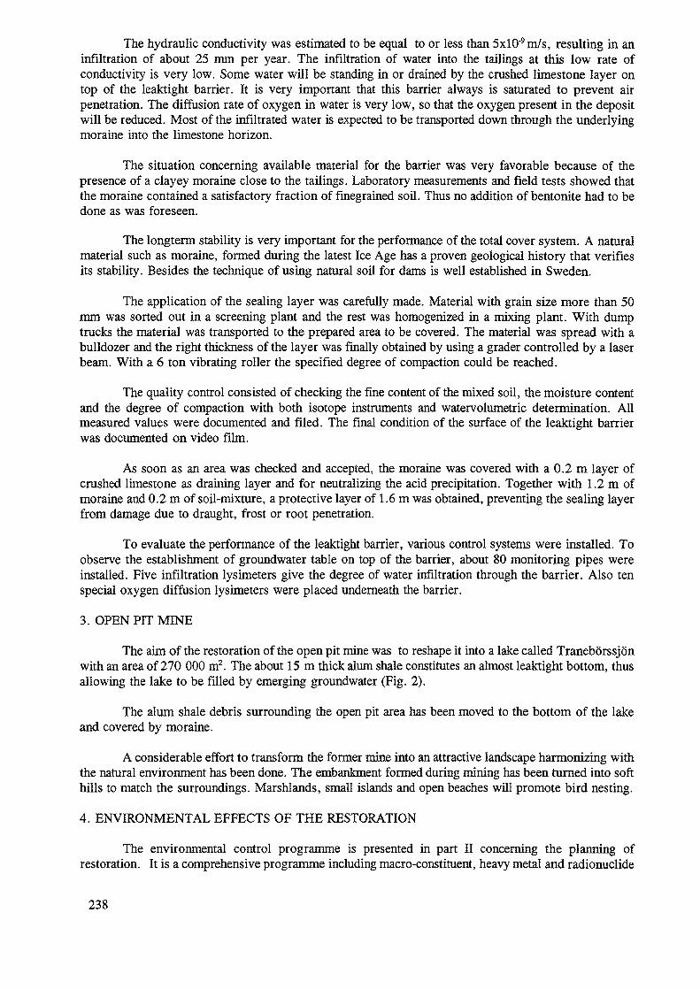
The hydraulic conductivity was estimated to be equal to or less than 5xlO'9m/s, resulting in aninfiltration of about 25 mm per year. The infiltration of water into the tailings at this low rate ofconductivity is very low. Some water will be standing in or drained by the crushed limestone layer ontop of the leaktight barrier. It is very important that this barrier always is saturated to prevent airpenetration. The diffusion rate of oxygen in water is very low, so that the oxygen present in the depositwill be reduced. Most of the infiltrated water is expected to be transported down through the underlyingmoraine into the limestone horizon.
The situation concerning available material for the barrier was very favorable because of thepresence of a clayey moraine close to the tailings. Laboratory measurements and field tests showed thatthe moraine contained a satisfactory fraction of finegrained soil. Thus no addition of bentonite had to bedone as was foreseen.
The longterm stability is very important for the performance of the total cover system. A naturalmaterial such as moraine, formed during the latest Ice Age has a proven geological history that verifiesits stability. Besides the technique of using natural soil for dams is well established in Sweden.
The application of the sealing layer was carefully made. Material with grain size more than 50mm was sorted out in a screening plant and the rest was homogenized in a mixing plant. With dumptrucks the material was transported to the prepared area to be covered. The material was spread with abulldozer and the right thickness of the layer was finally obtained by using a grader controlled by a laserbeam. With a 6 ton vibrating roller the specified degree of compaction could be reached.
The quality control consisted of checking the fine content of the mixed soil, the moisture contentand the degree of compaction with both isotope instruments and watervolumetric determination. Allmeasured values were documented and filed. The final condition of the surface of the leaktight barrierwas documented on video film.
As soon as an area was checked and accepted, the moraine was covered with a 0.2 m layer ofcrushed limestone as draining layer and for neutralizing the acid precipitation. Together with 1.2 m ofmoraine and 0.2 m of soil-mixture, a protective layer of 1.6 m was obtained, preventing the sealing layerfrom damage due to draught, frost or root penetration.
To evaluate the performance of the leaktight barrier, various control systems were installed. Toobserve the establishment of groundwater table on top of the barrier, about 80 monitoring pipes wereinstalled. Five infiltration lysimeters give the degree of water infiltration through the barrier. Also tenspecial oxygen diffusion lysimeters were placed underneath the barrier.
3. OPEN PIT MINE
The aim of the restoration of the open pit mine was to reshape it into a lake called Traneborssjonwith an area of 270 000 m2. The about 15m thick alum shale constitutes an almost leaktight bottom, thusallowing the lake to be filled by emerging groundwater (Fig. 2).
The alum shale debris surrounding the open pit area has been moved to the bottom of the lakeand covered by moraine.
A considerable effort to transform the former mine into an attractive landscape harmonizing withthe natural environment has been done. The embankment formed during mining has been turned into softhills to match the surroundings. Marshlands, small islands and open beaches will promote bird nesting.
4. ENVIRONMENTAL EFFECTS OF THE RESTORATION
The environmental control programme is presented in part II concerning the planning ofrestoration. It is a comprehensive programme including macro-constituent, heavy metal and radionuclide
238
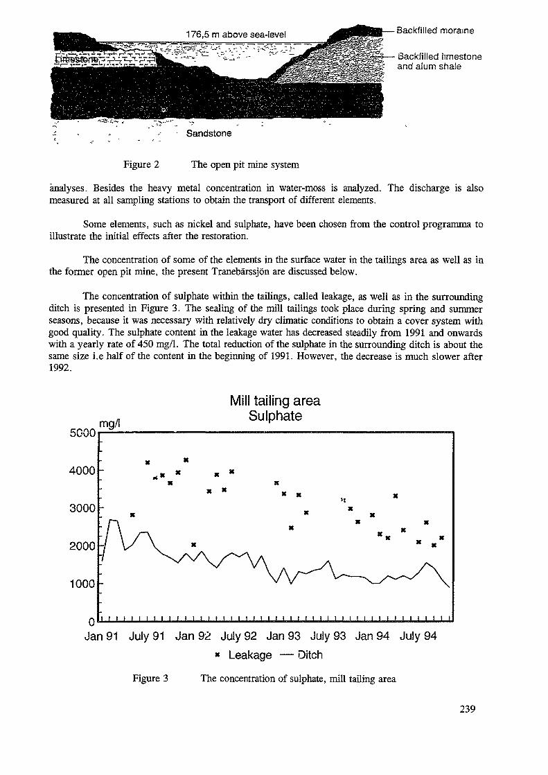
Backfilled moraine
Backfilled limestoneand alum shale
Figure 2
Sandstone
The open pit mine system
analyses. Besides the heavy metal concentration in water-moss is analyzed. The discharge is alsomeasured at all sampling stations to obtain the transport of different elements.
Some elements, such as nickel and sulphate, have been chosen from the control programma toillustrate the initial effects after the restoration.
The concentration of some of the elements in the surface water in the tailings area as well as inthe former open pit mine, the present Tranebarssjon are discussed below.
The concentration of sulphate within the tailings, called leakage, as well as in the surroundingditch is presented in Figure 3. The sealing of the mill tailings took place during spring and summerseasons, because it was necessary with relatively dry climatic conditions to obtain a cover system withgood quality. The sulphate content in the leakage water has decreased steadily from 1991 and onwardswith a yearly rate of 450 mg/1. The total reduction of the sulphate in the surrounding ditch is about thesame size i.e half of the content in the beginning of 1991. However, the decrease is much slower after1992.
5000
4000
3000
2000
1000
mg/l
ill tailing areaSulphate
X * X X
I I I I I t I I 1 I I I I I I I I I I I i I I 1 I I I I I I I I I I I I I I I 1 I0" ' M IIJan 91 July 91 Jan 92 July 92 Jan 93 July 93 Jan 94 July 94
* Leakage — Ditch
Figure 3 The concentration of sulphate, mill tailing area
239
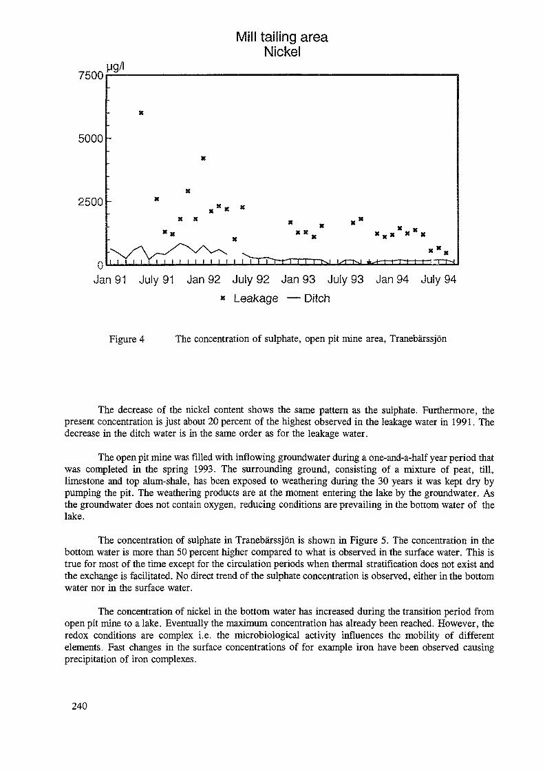
ill tailing areaNickel
7500
5000
2500
v
8 X
* X x.x * "x
Jan 91 July 91 Jan 92 July 92 Jan 93 July 93 Jan 94 July 94» Leakage — Ditch
Figure 4 The concentration of sulphate, open pit mine area, Tranebarssjon
The decrease of the nickel content shows the same pattern as the sulphate. Furthermore, thepresent concentration is just about 20 percent of the highest observed in the leakage water in 1991. Thedecrease in the ditch water is in the same order as for the leakage water.
The open pit mine was filled with inflowing groundwater during a one-and-a-half year period thatwas completed in the spring 1993. The surrounding ground, consisting of a mixture of peat, till,limestone and top alum-shale, has been exposed to weathering during the 30 years it was kept dry bypumping the pit. The weathering products are at the moment entering the lake by the groundwater. Asthe groundwater does not contain oxygen, reducing conditions are prevailing in the bottom water of thelake.
The concentration of sulphate in Tranebarssjon is shown in Figure 5. The concentration in thebottom water is more than 50 percent higher compared to what is observed in the surface water. This istrue for most of the time except for the circulation periods when thermal stratification does not exist andthe exchange is facilitated. No direct trend of the sulphate concentration is observed, either in the bottomwater nor in the surface water.
The concentration of nickel in the bottom water has increased during the transition period fromopen pit mine to a lake. Eventually the maximum concentration has already been reached. However, theredox conditions are complex i.e. the microbiological activity influences the mobility of differentelements. Fast changes in the surface concentrations of for example iron have been observed causingprecipitation of iron complexes.
240
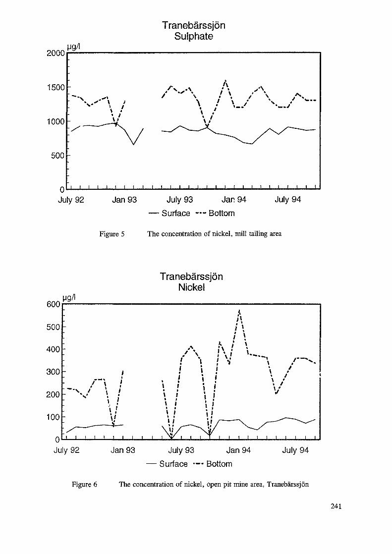
2000 M9/1
TranebarssjonSulphate
1500
1000
500
0 i i
July 92 Jan 93 July 93 Jar. 94— Surface — Bottom
July 94
Figure 5 The concentration of nickel, mill tailing area
600
TranebarssjonNickel
92
Figure 6
Jan 93 July 93 Jan 94 July 94— Surface •-- Bottom
The concentration of nickel, open pit mine area, Tranebarssjon
241

5. CONCLUSIONS
We can conclude, two years after the sealing of the mill tailings, that the cover system worksproperly. The observed infiltration of precipitation is very low, less than five percent of the precipitation.No oxygen penetration through the leaktight layer has so far been observed. The concentration ofpollutants as uranium and heavy metals is decreasing. However the reduction is slow and it will take someyears before the purification of the leakage water can be terminated.
242
TECHNOLOGIES FOR ENVmONMENTAL RESTORATIONIN UKRAINE
C. RUDYMinistry for Environmental Protectionof Ukraine, Kiev
O. AVDEEVR&D Institute for Decontamination andWaste Management, Zovti Vody
Yu. SOROKAR&D lastitute for Industrial Technologies,Zovti Vody
G. PEREPELIATNIKOVR&D Institute for Agricultural Radiology
S.SAVERSKYScientific Department of the RestrictedZone Administration
Ukraine
Abstract
This paper provides examples of restoration approaches in Ukraine for contaminated sites of variousnature and origin. Advantages and disadvantages of such approaches are also described.
Forestation proved to be the most effective counter measure to bind radionuclides 'in situ' and preventresuspension mechanisms in the Chernobyl restricted zone. Another protective measure in this zone isthe erection of dams to prevent contamination spreading floods. The restoration programme in livingores mainly include upper soil removal, demolition and removal of roofs, fences and wall plasters,asphalting, and transportation of secondary wastes to the waste disposal site. Additional measures toreduce internal exposures include agrochemical measures and milk filtration. Such aspects aredescribed in detail in this paper. A separate section deals with restoration of sites contaminated byuranium mining and milling activities.
I. INTRODUCTION
During previouse stages of the RER/9/022 it was confirmedand illustrated that restoration of environment, contaminatedwith ridionuclides is not a mere decontamination process, butrather a complex planned activity involving policy leveldecisions, sophisticated system of criteria, comprehansivefinancial arrangements.
Restoration includes application of tecnologies fordecontamination, in-situ stabilisation and isolation of
243
radionuclides, as well as special agrochemical measures toreduce nuclide transformation into chemically movable forms,their release and migration into food chains. Restorationtechnologies were applied in Ukraine in uranium industrystarting1 from the early period of the uranium output, but onlycomparetively recently the development of systematic criteriawas began. Chornobyl accident recovery operations provided theunique information for environmental impact of radiation aswell as experience of application of wide range ofenvironmental restoration activities.
Below are given examples of restoration approaches forcontamination cases of different nature and origine as theywere realized or planned in Ukraine with all positive andnegative features proven by practical experience.
2. POST-OXMfiBYL RESTORATION
£.1. Restricted Zone.Experience of the Chornobyl zone recovery activities
demonstrates extremely low efficiency of the directdecontamination measures. Thus, it -was shown that with averageimmediate decontamination factor of 1.2 - 1.5 the estimatedcollective dose for personnel participating in decon workexceeds 15,000 Sv. There is no data on the ultimate- efficiencyof 'those decon operations, because it was shown that in anearly post-accident stage, after the certain period,decontaminated anolaves normally were , recontaminatedpractically 'to the previous levels. For settlements someeffect became visible after the nomber of the similar deconcycles.
Up to date decontamination works were performed on 2250hectars of land in the Restricted Zone, complex restorationmeasures were done on 2400 hectars. It was shown thatforrestation is the most effective counter measure to bindradionuclides "in-situ" and prevent resuspention mechanizms.Though pine-tree forrest fires represent the other mechanismfor radionuclide release. During fire up to 90% ofradionuclide inventory could be released with smoke gases andcarried to, the long distances.
Example of another environmental restoration approach isa complex protective measures of the river Pripiat
244
flood-planes in the- vicinity of Chornobyl site, which washighly contaminated after the accident in 1986.
detaled information on the contamination levels isgiven in -the relevant report presented at the First RER/9/Q22workshop in Budapest.
• There is .no inhabitants and .economic (agricultural)activity directly connected with these areas, as they arewithin so-called Restricted Zone, with all populationevacuated in 1986 year. Still, considerable risk is connectedwith Sr-90 and Cs-137 migration to the basin of river Dnipro,which is the' main source of drinking and irrigating watersupply in Ukraine, especially for it's Southern regions.
The main problem with planning of restoration activitiesfor restricted zone connected with the vast dimensions of thehighly contaminated flood- planes areas, and the need forimmediate .actions, because- every next year reduces theeffectiveness of such measures. The- first factor requires anapplication of water protective measures directed to isolationof nuclides' in-situ and -prevention of ' flooding the. mostcontaminated parts. Water protection approaches includeerection of flood protecting dams along the main channel- ofriver'Pripiat and surrounding dams around most contaminatedflood-plane parts. Still, the ultimate effectiveness of thesemeasures, including collective dose reduction is not provenyet. The main income of Sr-90 into Pripiat and -Dnipro basintakes place from less contaminated, but -much larger areas of'Ukraine, Belorus and 'Russian outside the Restricted Zone.General picture of contamination flood-planes near theChornobyl site is shown -in Fig. 1. .
2. 2. Living Areas Restoration Programme.Restoration Approach
Chornobyl accident caused contamination of 1779settlements in Ukraine with level of contamination exceeding 1Ci/sq. km. In accordance to Chornobyl legislastion specialprotective • countermeasures should be implemented to thepopulated areas where dose limit due to Chornobyl accidentexceeds 1 mSv/year. This criterion was put into basis of aliving area restoration count ermeasures.
245
Below is given a typical example of restorationtechnologies and countermeasures for one of the villages inthe Rivne region of Ukraine. The contamination level for thiszone falls within 37 - 185 kBq/sq. m (1 - 5 Ci/sq. km). Majorbulk of radionuclides are concentrated in the upper 10 cmlevel of soil. Typically, the main constituent of the totaldose is due to internal exposure (85 - 95%). Thus, for theexample illustrated on Fig. ...-..., average contaminationlevel is 3.95 Ci/sq. km (146 kBq/sq. m), annual individualequivalent dose comes to 3,78 mSv/year, 0.51 mSv/year of it isdue the external exposure, and 3.27 mSv/year - internalexposure, 80% of the latter is due the local milk and ' diaryproducts consumption.
Measures for external dose reduction include:- upper soil removal in spots were dose rate exeedes24 mkR/h;
- roofs, fences-and wall plaster removal;- asphalting of the yards and rain drainage areas;- transporting of the secondary, wastes to the wastedisposal site.
Internal exposure reduction is , perfomed by followingmeasures:
- agrochemical measures (ploughing, fertilising, liming);- filtration of milk;- administrative and organisational measures (cleanproducts supply, local food products monitoring and^control, change of local habits and traditions, etc.).
Restoration area includes the territory of the village,and ajasent 500-m "protective zone". Fig. 3 illustratestypical contamination level characterisation plan which is thebase for restoration works.
At each individual farmer estate restoration measuresinclude removal of the strip of soil adjacent to the buildingswith width of 1 m to the depth of 0.1 m. Resulting wastes withthe levels' of exposure dose rate more than 24 mkR/hr aretransported to the waste disposal sites (to be describedlater). If exposure dose rate from wastes does not exceed- 24mkR/hr, this soil is used for road sides and land filling.
246
It should be noted, that in view of dominating internalexposure dose fraction, the most effective dose-redueingmeasures are the agrochemical ones, which include fertilizing,liming and sorbent adding (zeolite, etc.), which in moredetail are highlighted in the section 2.5.
tote ManagementThe plan view of the typical waste disposal point (WOP)
is given at Fig. 4.
The main requirement for the WDP'siting is an isolationof wastes from the environment for the period of 10 Cs-137decay half-lives. Water table depth should not be less then 4m from the bottom of the trench. WDP is usually sited at theelevated points of the local relief (hills, etc.).
.VDP/typical design features are:- dimensions in plan: 100x60 m;- slope angle: 1 : 5;- depth of the trench: 2. 5 m.The cross-sect ion of the WDP is shown on Fig. 5. The
bottom of the trench is covered with lower isolation claylayer with thickness of 0.5 m. Resulting filtrationcoeffitient k is 10E-4 in/day, and provides full decay ofradionuclides while they finally penetrate through theisolation layer. The depth of the nuclide migration throughthe clay sheat before the full decay for Cs-137 and . Sr-90 isapproximately 0.02 m and 0.36 m, respectively.
Upper isolation layer has multilayer structure.Radioactive wastes are covered by gas drainage sand layer,with variable thickness from 0. 5 m in the center to 0 m at theedges. In this' layer ceramic drainage duct is placed. Sandlayer is covered with 0. 5 m hydro isolation clay layer which issimilar to -the bottom one. Next is a 0.3 m sand layer fordrainage of the precipitations into outer circular drainagetrench. Upper layer is a fertile soil layer of 0.3 m.Vegetation is planted over the upper layer to prevent erosion.
247
Waste loading into VDP is perfomed sequentially bytracks. Each layer is temped by roller. To prevent dusting thesurface of the layer is sprinkled with water. Radioactivewastes of organic nature are put inside the bulk of thenon-organic wastes with a layer of 0. 5 - 0. 4 m. In more detailfilling technology of the waste disposal point is illustratedin Fig. 6.
After filling of the trench and covering it with fertilesoil, vegetation is planted on the top surface of the'depository to prevent erosion.
2. 4. Selective Soil Removal System.
Experience of the early stage of the Chornobyl accidentrecovery operations shown the need in an effective soilremoval units which would allow selective removal ofcontaminated soil depending on the contamination level of thesoil suface. This would allow to reduce the quantity ofradioactive wastes to be disposed or processed.
Fig. 7 shows the schematic diagram of the selective soilremoval unit which is designed to perform removal of the uppersoil layer in correlation with the dose-rate level in fourindividual strips.
It has four independent measuring and control channelsallowing selective removal in four parallel" strips of soil.-System has a tram configuration with tree principal elements:hauler (1), soil removing unit, and changable trailing truck(13) to accumulate and transport removed soil.
Hauler (tracktor, tank, etc.) has a shielded cabin andair conditioning system to prevent unacceptable exposure oftwo operators, one of which is a driver. In front of thehauler there is a detector group' (2) consisting of foursensors in^collimating cylinders (3). Viewing angle of eachsensor is 20 . To let control of the soil removal mechanism adetector transducing unit (4) and hydrosystem (5) to drive thesoil removal mechanism are also installed at the vehicle.
t
Soil removal part is in more detail shown at Fig. 8. Itconsists of four through bowls (12), each having individual
248
hydrodriving mechanism (14) controlled in. correlation withdose rate measurements in each individual channel. Each bowlhas limiting apron'(13), 'which prevents -bowl from overdeepinginto the soil and controls the thickness of the removed soil.To suppress dust that could be raised with dry soils, watersprinkling unit is mantled consisting of two water tanks (19),piping' with valves (20) and two sprinklers (21).
As it was shown that even eight years after the accidentthe main bulk of radipnuclides (up to 95£) is concentrated inthe-upper 5-cm layer of the. soil (see Table I), the device forsoil removal does not need to have capability to change thethickness of the removed layer during the same run. it can beajusted prior the' definit set of runs on the basis of more •detailed investigation of the soil properties of theparticular area to be developed. 'The last part of the systemis an open changable trailed truck to accumulate removed soiland deliver it to the waste disposal point. •
2.5. Agrochemical Measures.Fig. 9 demonstrates that 5-7 years after Chornobyl
accident major fraction (70-95%) of the total dose incontaminated -areas is due to internal exposure. Nearly 80% ofthis part is 'caused by milk consumption, thus making ofspecial importance the problem of production of clean foragecrops. .
The main agrochemical countermeasures include:Mechanical treatment:
- Ploughing, cultivation- Drainage
Chemical:- Liming- Addition of fertilizers- Addition of absorbing .compounds (clay, zeolit).
249
The effectiveness of these counermeasures depends on thespecific hydrogeological and soil characteristics and land useclass of the each particular site of application. Regionscontaminated with Chornobyl radionuclides generally have poorsoils of soddy-podzol, sandy and peaty type with poor top-soillayer, and in original condition are characterized withrelatively high soil-plant transfer factors.
Ploughing is a comparetively cheap and practicalcountermeasure allowing to achieve the reduction of surfacecontamination from 2 up to SO- times, depending on thethickness of" the inverted layer of soil. Combination of
•ploughing with application of some compounds, such .as amixture of sodium carbonate ' and isopropylphenyl carbonate,which prevent roof intrusion, can reduce uptake, of Sr-90 byagricultural crops up to 1000 times.
Drainage is an effective countermeasure on the moisturouspeaty meadow soils, and could reduce the nuclide uptake by' afactor of 3.
Addition of •fertilizers could have different effectdepending on soil characteristics, type or-the fertilizer andcomposition of the fertilizer-additives mixture. Addition ofpotassium fertiliser though generally positive, could be noteffective for soils reach'in potassium or clay soils. Additionof either nitrogen or phosphate fertilizers increases Cs-137uptake. Fig. 10 illustrates the effect - of differentfertilizers to the yield and uptake- of Cs-137 by'oats andpotato. It should be noted that this effect is generally varydepending on the fertilizer doses.
Natural meadow melioration investigation with respect tosoil-plant transfer ratio for Cs-137 gives the followingresults. Drainage reduces uptake up to 3 times, soil treatment- up to 4 times, addition of potassium fertilizer - up - to 3times, the same with lime - 4 times, respectively. Complexcountermeasures including all listed measures could reduceCs-137 uptake to 16 times. Table II gives illustration of thecomparetive effectiveness of different agrochemicalcountermeasures in application to a peaty meadow soil.
Table III gives comparative figures of • soil-planttransfer factor for different forage crops for the sameconditions of drained peaty soil. Table IV gives illustration .
250
of the impact of different meliorants to soil-plant transferfactor for different forage crops. It can be seen that themaximum effect has the elevated doses od potassium fertilizers,in a mixture with complex mineral fertilizers, lime andmanure.
Addition of lime is a universal effective measure, but itcould be of low effect in an already calcareous soils.
3. EXPERIENCE OF ENVIRONMENTAL RESTORATION IH REGIONSOF URANIUM MILLING AMD MINING INDUSTRY
Uranium milling, and industry . is concentrated inKirovograd, -Dnipropetrovsk and Mykolaiv regions of Ukraine. Intotal uranium milling, and mining industry occupies 5530hectars of land*. 1340 ha are damaged.
Prevailing contamination path .for, waste rock piles isnatural leaching of radionucl ides with rains and snow meltingwaters. Fig. 11 - 14 sho'ws processed curves of nuclide contentand alpha-activity in 1-meter layer of soil at the site ofrelocated uranium ore stock. Table V contains referencefigures for samples taken at 10-20 m distance from this formerstock.
Comparison'of given data shows that at the vicinity ofore stock there are elevated quantities of U-238 and Pb-210 atthe depth up to 1 m, while Po-210 - only at the surface. Thus,contamination of the soil at the site of former stock exceeds1 m depth, and in the ajiacent area of 10 - 20 m width iswithin 1 m depth. Fig. 15 .shows results of soil, plant and aircontamination survey in terms of exceeding the backroundreference level. It demonstrates that the area affected bywaste rock-piles reaches 700 - 800 meters.
At Zovti Vody 'Site the most powerful source ofenvironmental contamination is represented by two milltalings. Exhalation of Rn-222 and resuspention of dry tailingsandy beaches provides two major mechanisms of environmental.,contamination. Rn-222 exhalation rate is 0.05-3.0 Bq/sq. m*s.Avar age zone of mill tailing influence for Ra-226 reaches 1300m, and Po-210 - up to 1800 m (above background levels).
251
Restoration of lands affected by uranium mill ing andmining practice in former USSR started in the mid-seventies.The' main restoration critera were introduced . .by specialSanitary Regulation (CII-1324-75). According to this guidance,the final contamination after finishing restoration activitiesshould not exceed background level by 2 times. At limitedportion of restored area (limited by 20% of total area)residual contamination could exceed background level by 3times. ; , / ' • • •
Project for" restoration of waste rock piles was developedin Zovti Vody including two options of. restoration . measures.First option provides for smothening of pile slopes, coveringwith restoring layer, and finally, plant if icat ion of therestored are.a. Second option propose relocation of the wasterock into nearby natural pit , covering with restoring layer',and pi ant if icat ion of the restored area in the same mode.Table VI shows cost characteristics of both options in moredetail. Restoration .layer reduces Radon exhalation from 0.95to 0.084 Bq/sq. m*s, or 10 times. . •
Waste rock pile that existed in Zovti Yody in late'seventies was removed into the' giant cave-in pit that wascreated at the site of former iron underground mining cavity.General view of the waste rock pile-before the relocation isshown in Fig. 16 and 17. The general volume of waste rock.relocated in the cave-in pit is 400,000 cubic meters. Fig. ISshows the general view of the cave-in pit were this waste rockwas relocated, and Fig. 19 shows the process of f i l l ing thepit. Partially materials from the pile were used as a depleteduranium ore to extract residual uranium, thus reducing thevolume of waste rock and increasing the mil l tailing- part.
Cross-section of the mill tailing restored in Zovti Vodyis given in Fig. 20. As a result of covering with the firstclay layer of 0:4 m thickness the dose-rate on the surface - ofthe tailing was reduced- from 450-600 mkR/h to 24-56 mkR/h(background level is 24-56 mkR/h); radon exhalation wasreduced from 0. 05 - 20. 0 Bq/sq. m*s to 0. 028 - 10 Bq/sq. m*s.Planned technical and cost characteristics for differentoptions of mill tailing cover layer are given in Table V I I .
The main problem for the operated tailings is dusting oftheir dry beaches. Because the town of Zovti Vody is located
-in the close proximity to mil l tailings, this problem has the
252
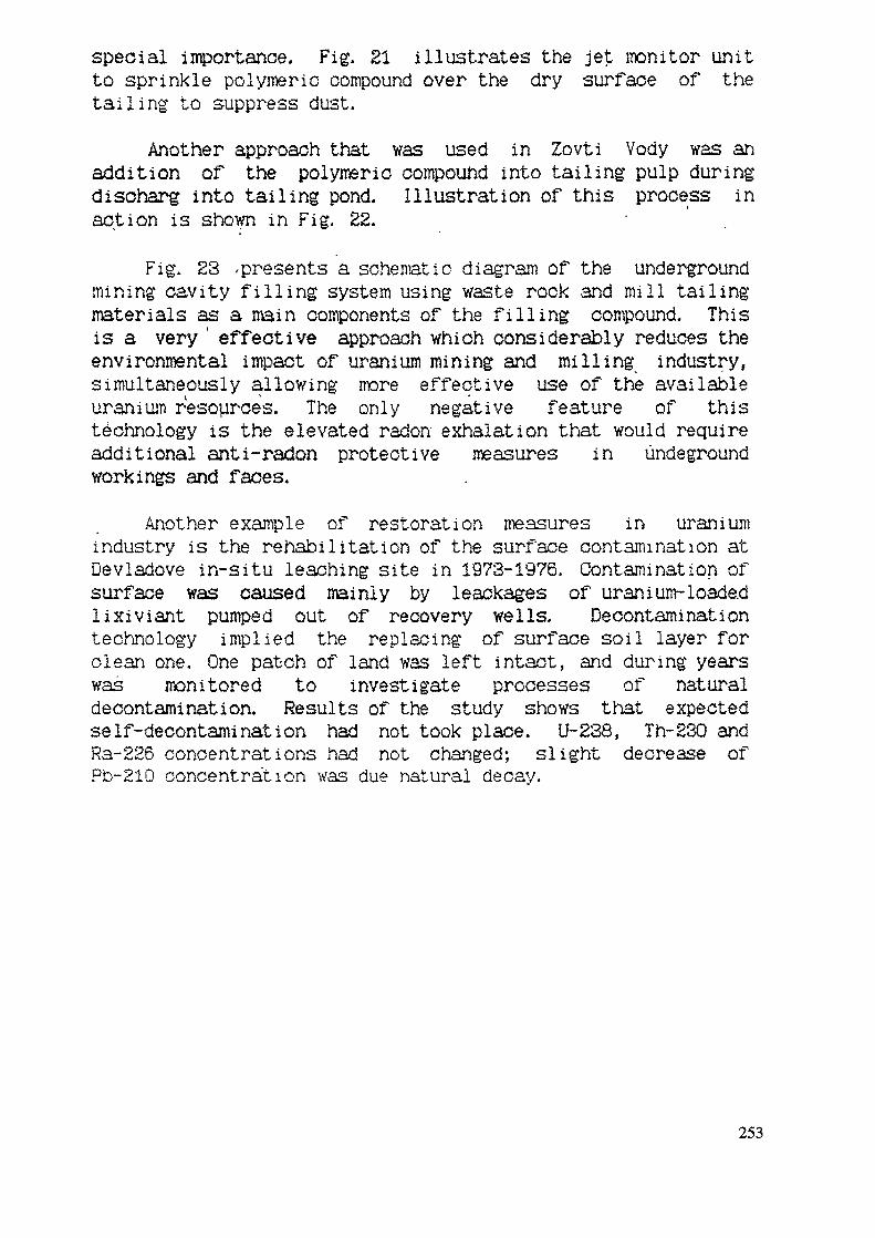
special importance. Fig. El illustrates the jet monitor unitto sprinkle polymeric compound over the dry surface of thetailing to suppress dust.
Another approach that was used in Zovti Vody was anaddition of the polymeric compound into tailing pulp duringdischarg into tailing pond. Illustration of this process inaction is shown in Fig. 22.
Fig. S3 ^presents a schematic diagram of the undergroundmining cavity filling system using waste rock and mill tailingmaterials as a main components of the filling compound. Thisis a very ' effective approach which considerably reduces theenvironmental impact of uranium mining and milling industry,simultaneously allowing more effective use of the availableuranium resources. The only negative feature of thistechnology is the elevated radon exhalation that would requireadditional anti-radon protective measures in undegroundworkings and faces.
Another example of restoration measures in uraniumindustry is the rehabilitation of the surface contamination atDevladove in-situ leaching site in 1973-1976. Contamination ofsurface was caused mainly by leackages of uranium-loadedlixiviant pumped out of recovery wells. Decontaminationtechnology implied the replacing of surface soil layer forclean one. One patch of land was left intact, and during yearswas monitored to investigate processes of naturaldecontamination. Results of the study shows that expectedself-decontamination had not took place. U-238, Th-230 andRa-226 concentrations had not changed; slight decrease ofPb-210 concentration was due natural decay.
253
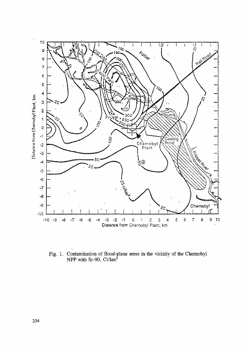
CL 2 -
CDJCO
o
Q
- 1 0 - 9 - 8 - 7 - 6 - 5 - 4 - 3 - 2 - 1 0 1 2 3 A 5 6 7 8 9 10Distance from Chernobyi Plant, km
Fig. 1. Contamination of flood-plane areas in the vicinity of the ChernobylNPP with Sr-90, Ci/km2
254
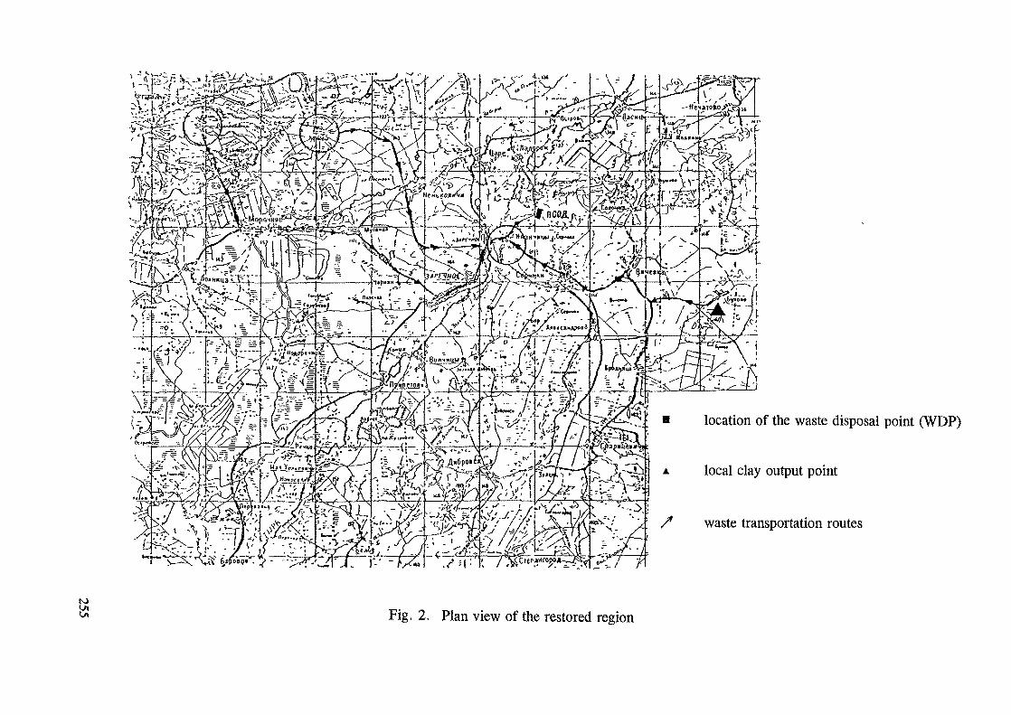
^i^S^^fe^ 2§Sd^t. ^^/^^SXj^^sJC'"*" ^-^l/ '
%M\y y^^^H5-/A ' v JL->5 v\ >r>lv- '.fj...^ <:-^_
\ :"? t
;^^7l;-\-/v\rTr1
location of the waste disposal point (WDP)
local clay output point
/ waste transportation routes
toFig. 2. Plan view of the restored region
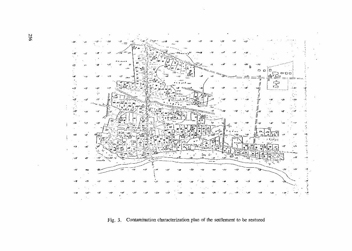
U>O\
. /? -It
-f7 -'f
•a -n -tt -/j v3" .//
•-/« '*r
•K .,4 -/f
•/*•
•/V -to
~T^r^£:3T^"^'\ - •"'.„ .„ ^:^^^k2\-« -
•/f -/f -x<- -II ./3 .// ,tf -/s -JP •' •& -to -f -Sf -/f -Jf
•Sf •& 'W
Fig. 3. Contamination characterization plan of the settlement to be restored
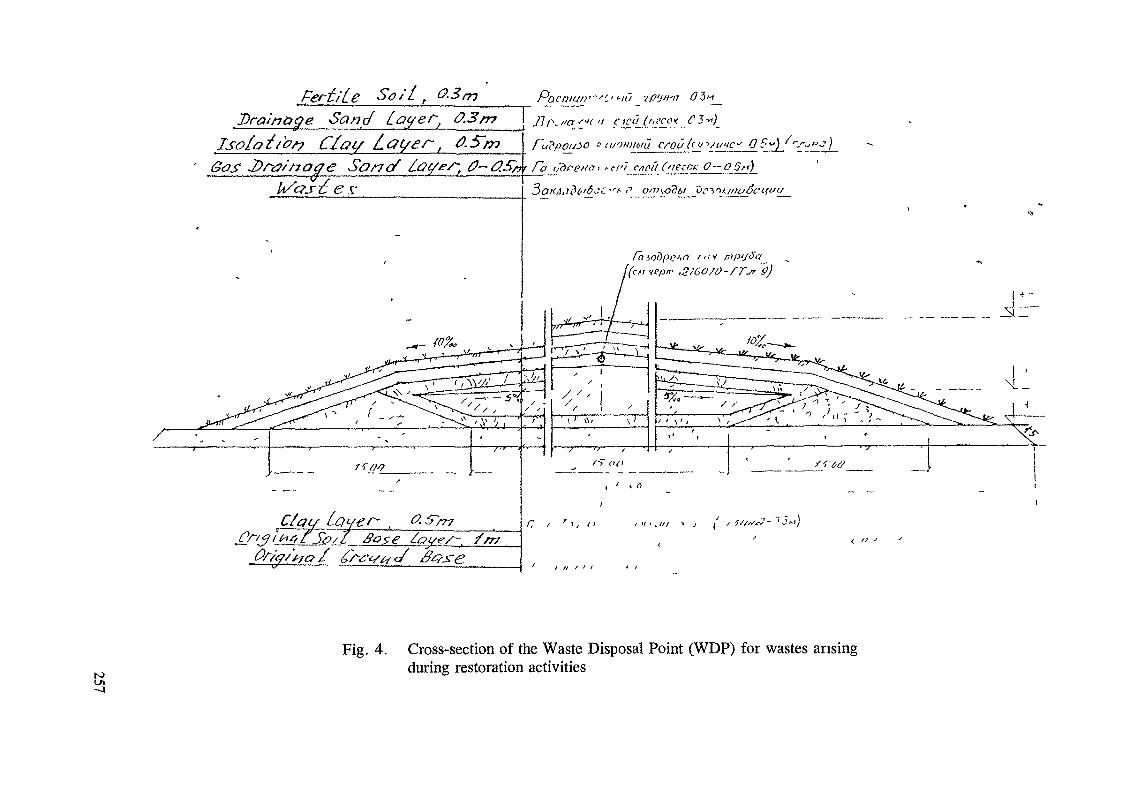
Isofottcs? Ctat/ Lat/es~,ca* 0-05^)
j/7 / ' • > , a / > / ' . / / / ! , (' / ?'/"J- "'""'j
Fig. 4. Cross-section of the Waste Disposal Point (WDP) for wastes arisingduring restoration activities
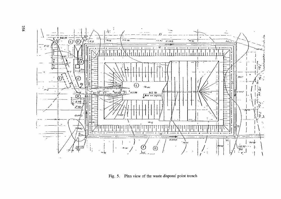
ao
Fig. 5. Plan view of the waste disposal point trench
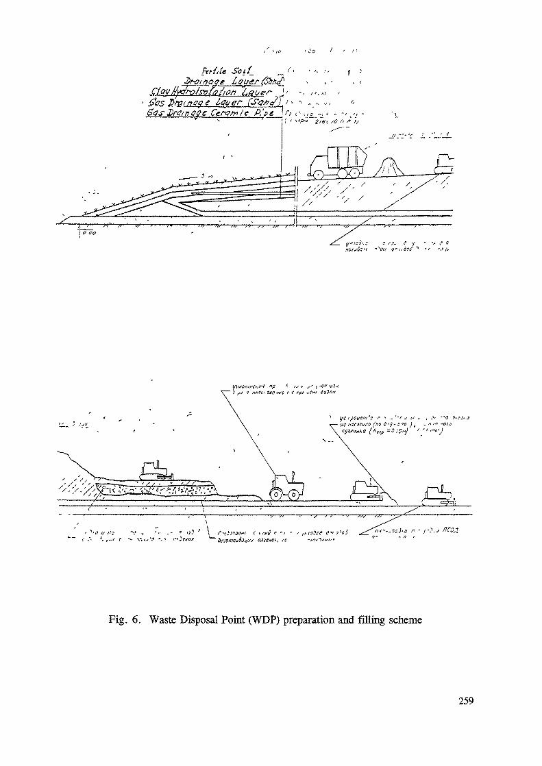
M.le Sotf_
,io / < /.
/. ,.»,. 1 ,
rat n aye I , -v
Gas£r$/fio$e Ccrgfr re P, >i ; f; <> vi_-, < /, -S———————————————————————————————— , , ^^J -Q^^ ^Q fl
/> >J
•: /. '. ,->/ r •» -i1-.,,'? -. > i'
Fig. 6. Waste Disposal Point (WDP) preparation and filling scheme
259
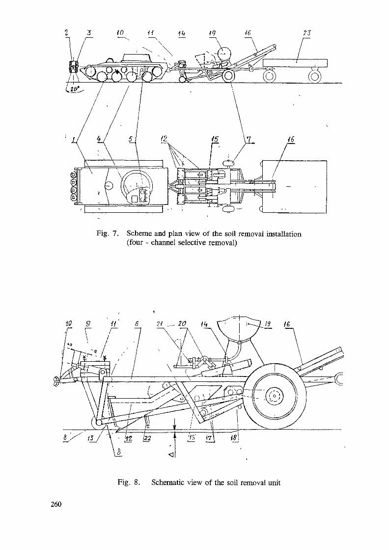
Fig. 7. Scheme and plan view of the soil removal installation(four - channel selective removal)
6 21 .... 20 it*
Fig. 8. Schematic view of the soil removal unit
260
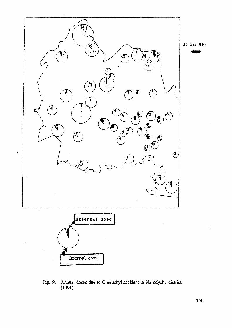
80 km HPP
Exte rna l dose
Internal dose
Fig. 9. Annual doses due to Chernobyl accident in Narodychy district(1991)
261
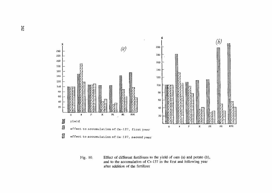
to
%%
240220200160160140120100eo604020
_ „_____.
- 1
1\'/
\\///
\
f/
™
E
^0 If P K
\FK
(o)
1-XK
1=JfFK
yield
effect to accumulation of Cs-137, first year
effect to accumulation of Cs-137, second year
200
180
160
140
120
100
00
60
40
20 /,f /
PK IfK XPK
Fig. 10. Effect of different fertilizers to the yield of oats (a) and potato (b),and to the accumulation of Cs-137 in the first and following yearafter addition of the fertilizer
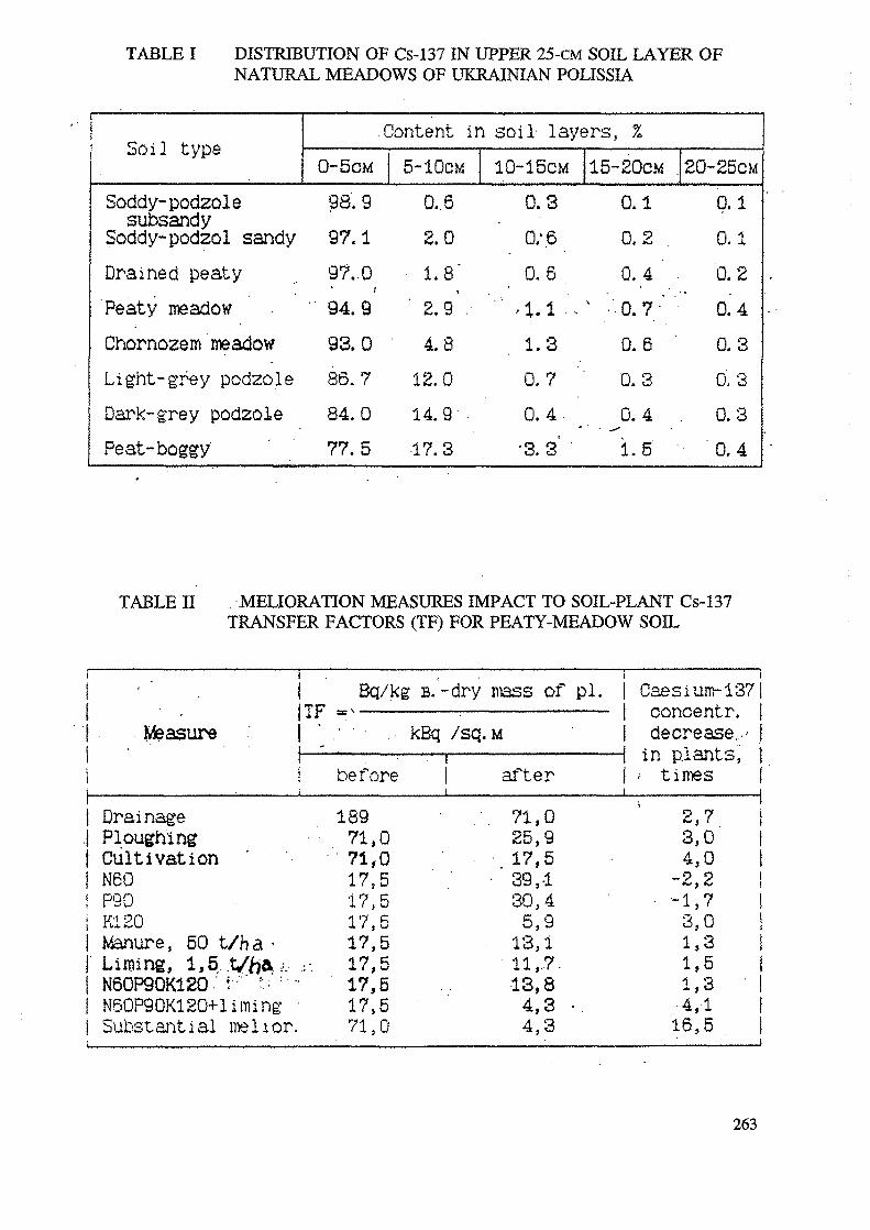
TABLE I DISTRIBUTION OF Cs-137 IN UPPER 25-CM SOIL LAYER OFNATURAL MEADOWS OF UKRAINIAN POLISSIA
Soil type
Soddy-podzolesubsandySoddy-podzol sandyDrained peatyPeaty meadowChornozem meadowLight- grey podzoleDark- grey podzolePeat- boggy
Content in soil layers, %0-5cM98. 997.197,094.993.086.784.077.5
5-10CM0,62.01.8"
' 2.9 .4.8
12.014.9' .17.3
10-15CM0.30;60.6
.-1.1 •1.30.70. 4 _'3. 3'
15-20CM0.10.20. 4 ' .
' • 0.7-' '0.60.30.41.5 '
20-25CM0.10.10.20.40.30.3
. 0.3'0.4
TABLE H MELIORATION MEASURES IMPACT TO SOIL-PLANT Cs-137TRANSFER FACTORS (TF) FOR PEATY-MEADOW SOIL
• ' . I BJTF «^-
Measure ! ' . ' • •
q/kg B. -dry mass
..- kBq
1 before1 ———————————————
DrainagePloughingCultivationN60
! P90K120
I Manure, 50 t/ha •[ Liming, 1,5 t//7& ; -.-i N60P9QK12Q ' t :•• : '\ N60P90K1 20+ l iming •
Substantial melior.
189717117•i?171717171771
st>ji
}
)
}
)
>
0055555550
/sq. M
of pi.——•
iafter
71,25,
.17,• 39,
30,5,
13,11,13,4,4,
095•14917.83 •3
Caesiuconcedecre
in p.la'• time
2,3,4,
-2,• "!'<-•,i,i,i,
•4,16,
un-1371ntr. Iase.,' jints', 1s !
t
7 i0 f0 I2 !7 !o !3 15 13 !1 i5 ii
263
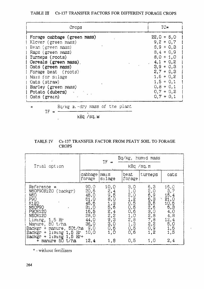
TABLE IE Cs-137 TRANSFER FACTORS FOR DIFFERENT FORAGE CROPS
ii Crops1 Forage cabbage (green mass)j Klover (green mass)1 Bean (green mass)i Raps (green mass)j Turneps (roots)| Cereals (green mass).| Oats (green mass)j Forage beat (roots)| Mais for silage1 Oats (straw)j Barley (green mass)j Potato (dubers) • •! Oats (grain)
i ii TO* j—— i ————————— ,22,0 i- 5,0 i9,2 + 0,7 i8,9 + 0,3 j8,4 + 0,9 18,0 + 1,0 i4,1 + 0,2 13,9 + 0,3 j2,7 + 0,3 |1,6 + 0,2 11,5 + 0,1 |0,8 + 0,1 j0,7 + 0,2 |0,7 + 0,1 1
* Bq/kg B. -dry mass of the plantTIT , , .
kBq /sq. M
TABLE IV Cs-137 TRANSFER FACTOR FROM PEATY SOIL TO FORAGECROPS
Trial optioncafo
Reference *N60P90K120 (backgr)N60P90K120
Bq/kg, humid massTFi r — kBq /sq. m
bbage maisrage silage30,0 10,020,6 2,445,0 9,561,0 8,045,6 1,3N60P90 . 31,0 5,6P90K120N60K120Liming, 1,5 HrManure, 50 t/haBackgr + manure, 50t/haBackgr + liming 1,5 HrBackgr + liming 1,5 Hr++ manure 50 t/ha
16,5 2,428,0 2,244,0 9,336,, 0 3,09,0 0,610,0 1,012,4 1,8
beatforage3,01,02,01,20,50,50,61,02,81,30,50,60,5
turneps
6,32,06,9
oats
16,0o 7o, (15,46,3 -21,03,52,63,02,87; 89 9*w e *w0,91,21,0
10,6 '6,34,04,812,45,01,61,52,4
- without fertilizers
264
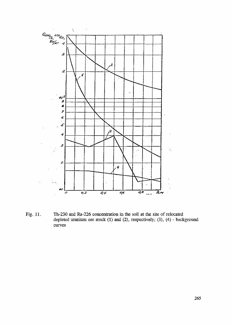
Fig. 11. Th-230 and Ra-226 concentration in the soil at the site of relocateddepleted uranium ore stock (1) and (2), respectively; (3), (4) - backgroundcurves
265
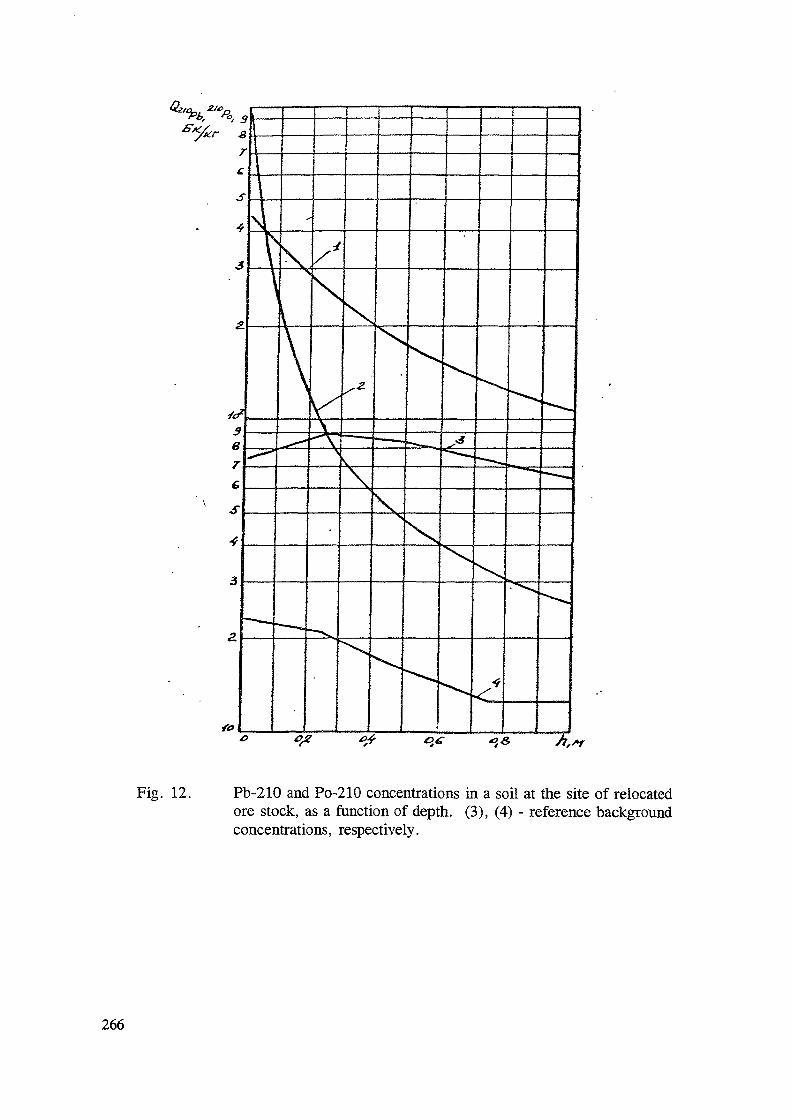
*4»
Fig. 12. Pb-210 and Po-210 concentrations in a soil at the site of relocatedore stock, as a function of depth. (3), (4) - reference backgroundconcentrations, respectively.
266
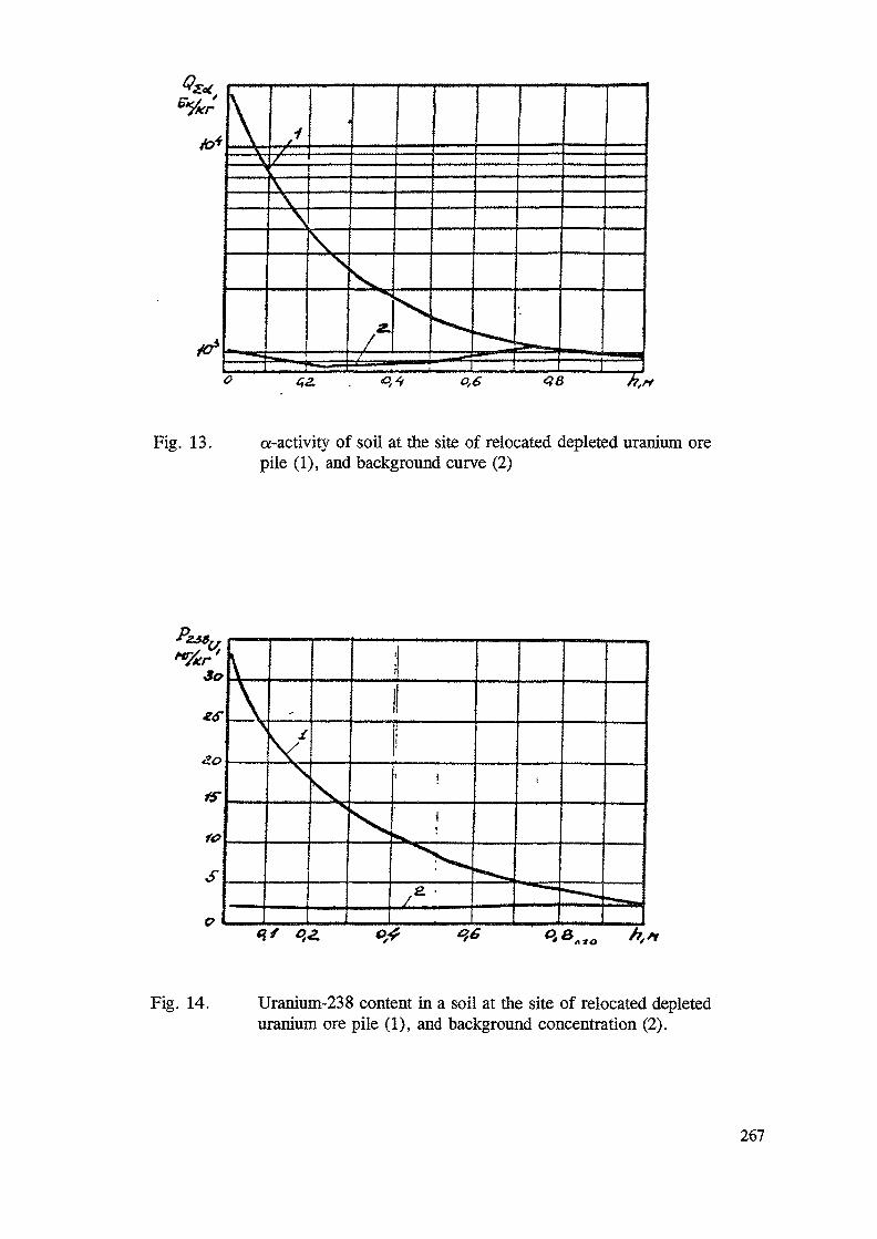
Fig. 13. a-activity of soil at the site of relocated depleted uranium orepile (1), and background curve (2)
Fig. 14. Uranium-238 content in a soil at the site of relocated depleteduranium ore pile (1), and background concentration (2).
267
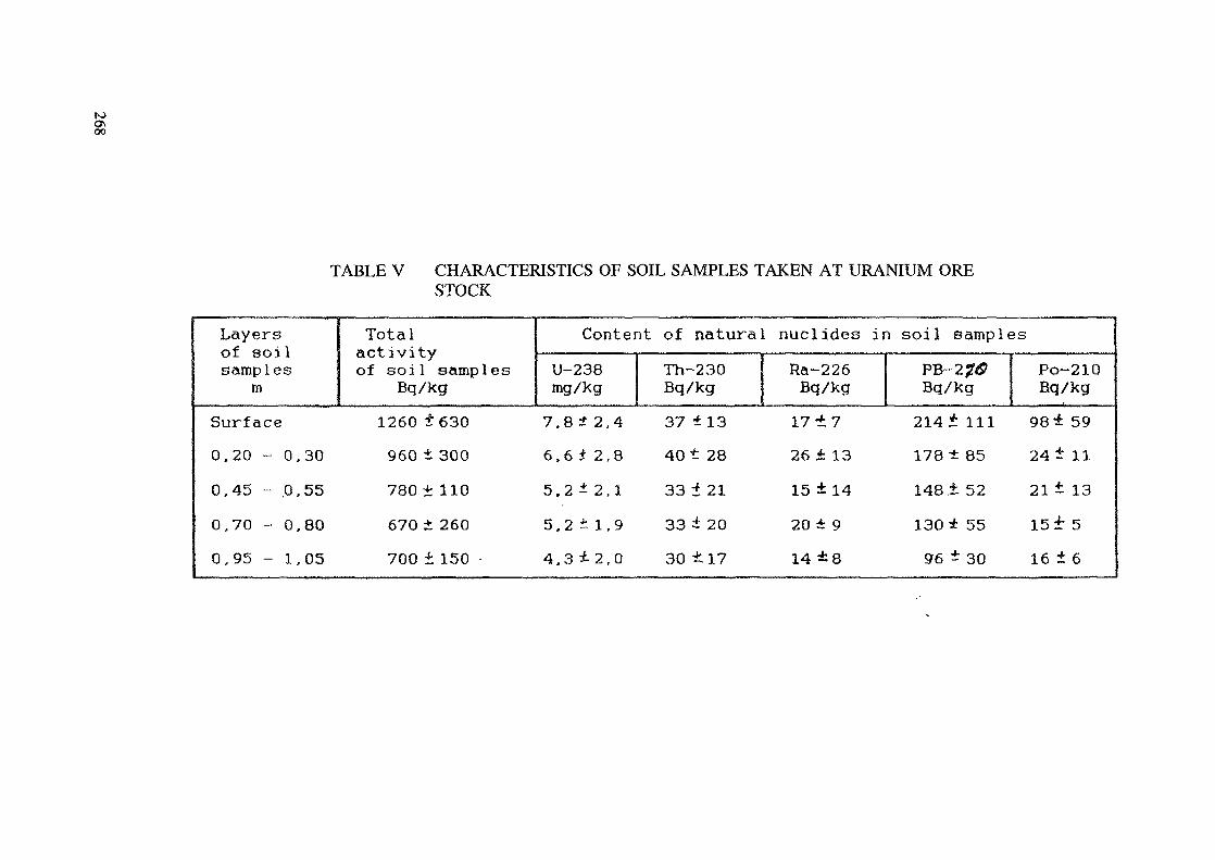
to&oo
TABLE V CHARACTERISTICS OF SOIL SAMPLES TAKEN AT URANIUM ORESTOCK
Layersof soilsamples
mSurface0.20 - 0,300,45 - .0,550,70 - 0,800,95 - 1,05
Totalactivityof soil samples
Bq/kg1260 ±630
960 t 300780 ± 110670 * 260700 ± 150 •
Content of naturalU-238mg/kg7.8 t 2,46.6 t 2,85.2 i 2,15.2 ±1,94.3 *2,0
Th-230Bq/kg37 ±1340 t 2833 1 2133 i 2030 ±.17
nuclides in soil samplesRa-226Bq/kg17 ±726 i 1315 ± 1420 ± 914 ±8
PB-2?#Bq/kg214 * 111178 * 85148.1 52
130 * 5596 ± 30
Po-210Bq/kg98* 5924 ± 1121 i 1315f 516 ± 6
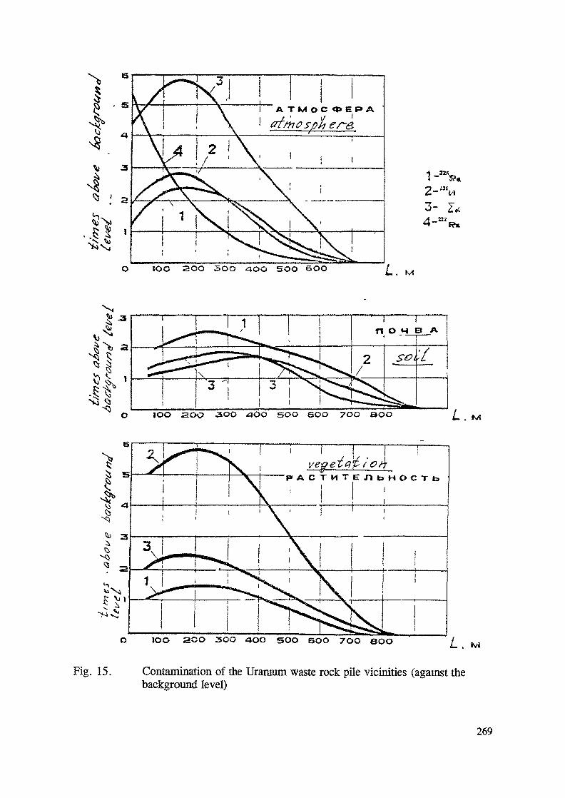
,__ 1A TM OC <*> E P> A
3- Z.C
1OO 2OO 3OO M
soo soo 700 BOO100 aoc> -300
P - A C T M T E T J b H O C T f aI i
SOO BOO 7OO OOOIOO 2CO 3OO
Fig. 15. Contamination of the Uranium waste rock pile vicinities (against thebackground level)
269
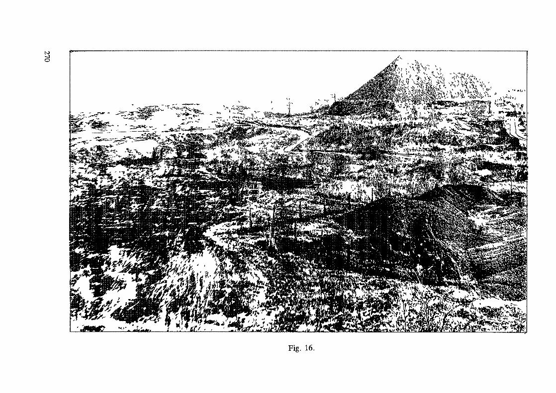
VOT——
I
bb
270
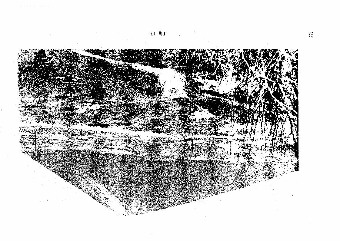
'LI -8i
• .•,_;-';'• v«-f---- V^>u«- - - *-^ •••^gf> ; —. ~ i, "UJT^^BffFv - • •? -*? * * '-•• ' '•
1 :5 si i ' :?fe^^^^ ^S^^^
»> ..:^^^^-€p?I^^U-^*?^?>C '*.3t-r-
"sgjpi'sStf/>'•. •'••;'««*•?!v, ?s* :' : '> • ••:;(w&>5%m."m^"^yVij. ' '. v . ••«3S^>r '-'*i';:: riu- - 'S* >v. '* : *vi
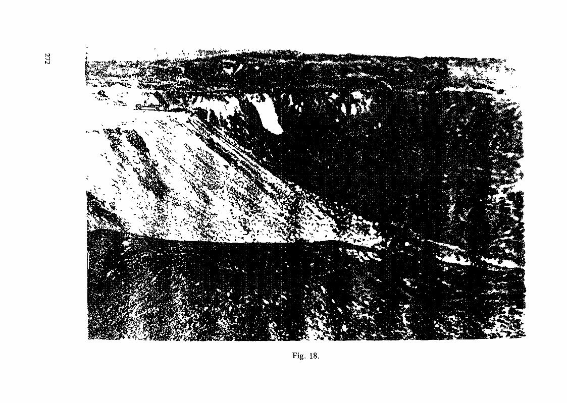
to
Fig. 18.
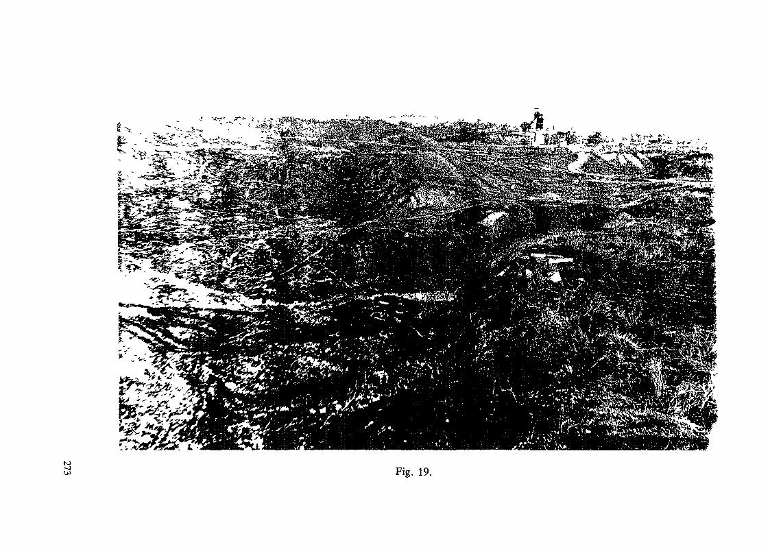
K)~JOJ Fig. 19.
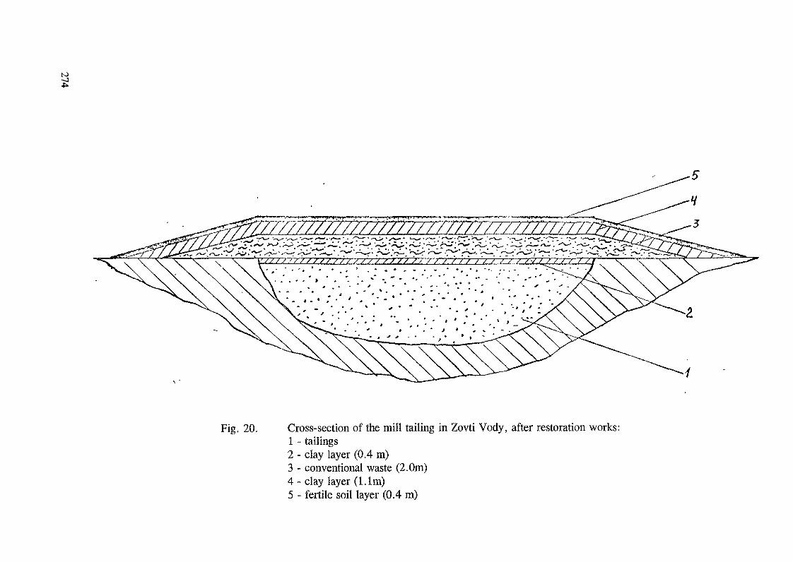
N>
Fig. 20. Cross-section of the mill tailing in Zovti Vody, after restoration works:1 - tailings2 - clay layer (0.4 m)3 - conventional waste (2.0m)4 - clay layer (1. 1m)5 - fertile soil layer (0.4 m)
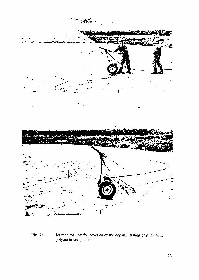
Fig. 21. Jet monitor unit for covering of the dry mill tailing beaches withpolymeric compound
275
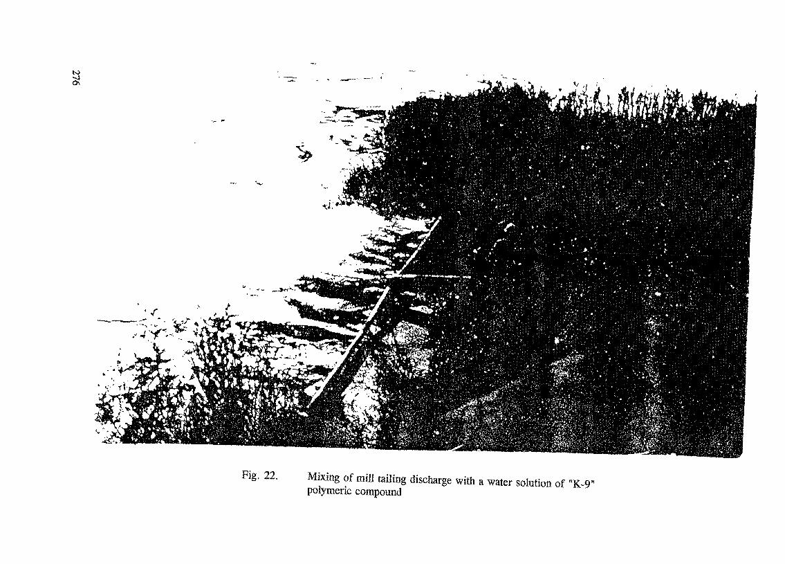
to
Fig. 22. Mixing of mill tailing discharge with a water solution of "K-9"polymeric compound
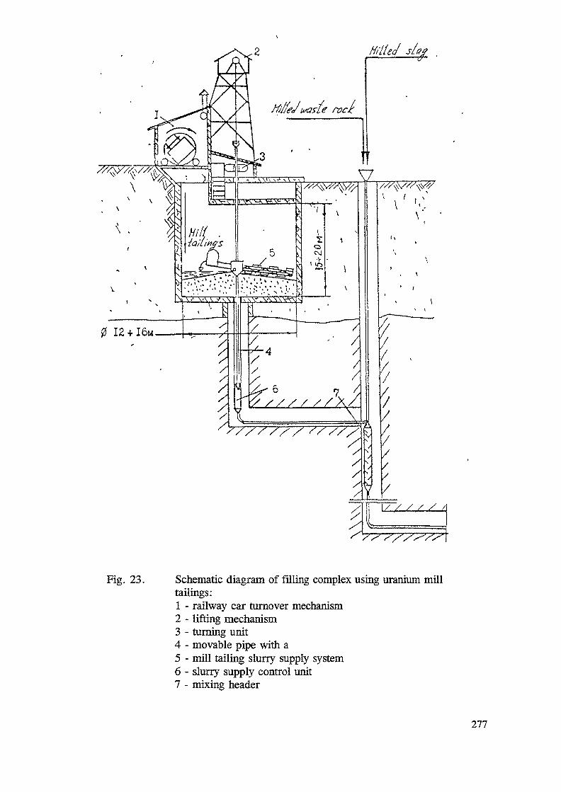
Fig. 23. Schematic diagram of filling complex using uranium milltailings:1 - railway car turnover mechanism2 - lifting mechanism3 - turning unit4 - movable pipe with a5 - mill tailing slurry supply system6 - slurry supply control unit7 - mixing header
277
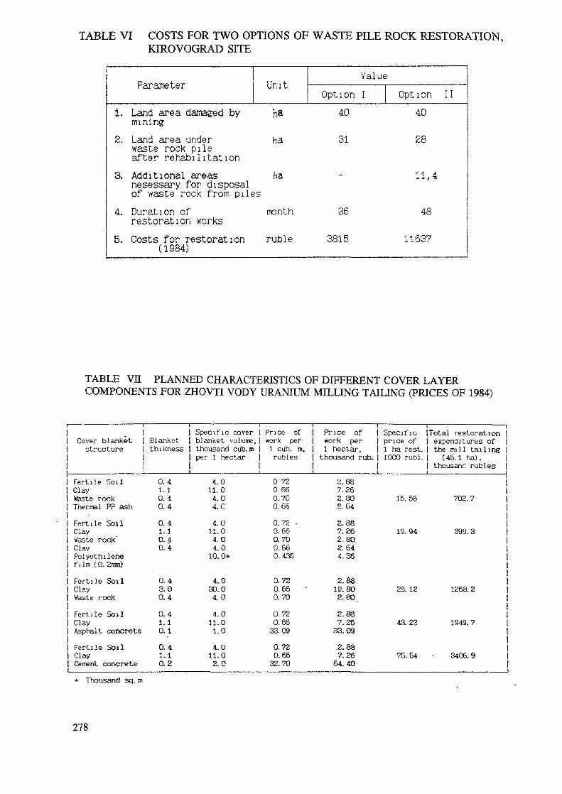
TABLE VI COSTS FOR TWO OPTIONS OF WASTE PILE ROCK RESTORATION,KIROVOGRAD SITE
Parameter1. Land area damaged bymining2. Land area underwaste rock pileafter rehabilitation
Unit
haha
ValueOption I
40
31
3. Additional areas hanesessary for disposalof waste rock from piles4. Duration ofrestoration works5. Costs for restoration(1984)
month
ruble
36
3815
Option 1140
28
11,4
48
11637
TABLE VII PLANNED CHARACTERISTICS OF DIFFERENT COVER LAYERCOMPONENTS FOR ZHOVTI VODY URANIUM MILLING TAILING (PRICES OF 1984)
i —— —————————— r1
Cover blanket |structure |
i
Fertile SoilClayWaste rockThermal PP ash
Fertile SoilClayVaste rock"ClayPolyethilertef i lm (0. 2mn)
Fertile SoilClayWaste rock
Fertile SoilClayAsphalt concrete
Fertile SoilClayCement concretei
Blanketthi kness
0.4i. 10.40.4
0.41.10.40.4
0.43.00.4
0.41.10.1
0.41.10.2
Specific cover 1blanket volume, |thousend cub. m |per 1 hectar |
1
4.011.04.04.0
4.011.04.04.0
10.0*
4.030.04.0
4.011.01.0
4.011.02.0
Price ofwork per1 cub. m,rubles
0 720 660.700.66
0.72 •0.660.700.660.436
0.720.660.70
0.720.66
33.09
0.720.66
32.70
_i ri Price of iI work per |I i hectar, j1 thousand rub. jI I1 i
2.887.262.802.64
2.887.262.802.644.36
2.8819.80
2. 80 _
2.887.26
33.09
2.887.26
64.40
———————— i —————————— iSpecific [Total restoration |price of I expenditures of1 ha rest, j the mi l l tailing j1000 rubl. t (45. 1 ha),
I thousand rubles
15. 58 702. 7
19. 94 899. 3
28. 12 1268. 2
4a 23 1949. 7
75. 54 - 3406. 9
* Thousand sq. m
278
REFERENCES
1. Avdeev 0. , Mosynets V. , "Ecological problems in UraniumMilling And Mining Industry".
2. L F. Vovk, V. V. Blagoev, A. N. Liashenko, I. S. Kovalev,"Technical approaches to decontamination of terrestrialenvironments in the CIS (former USSR)", The Science of the'Total Environzr&nt, 137, 49-63, Elsevier SciencePublishers B. V. , Amsterdam, 1993.
3. Scientific Bulletine of the Resrticted Zone, part 1,Chornobyl, 1994. "
279
METHODS AND TECHNIQUES USED TO REHABILITATERADIOACTTVELY CONTAMINATED SITES IN THEUNITED KINGDOM
L.R. FELLINGHAM, A.D. MORETONEngineering Services Division,AEA Technology, Harwell Laboratory,Oxfordshire, United Kingdom
Abstract
In the early years of use of radioactive materials the quality of control and waste managementpractices were of a considerably lower standard than those acceptable today. As a consequence alarge number of sites in the UK became contaminated to varying degrees with radioactive materials.The vast majority of these sites were very small in size and were linked to either radium or thoriumoperations or research applications. The net consequence of the above has been that the vast majorityof the rehabilitation work in the UK has been on a small scale and has not merited the use ofinnovative techniques. However, a number of innovative remediation techniques are underdevelopment in the UK for future cleanup programmes and some have attained full-scale application.These will be described in this paper. Three development areas are described in detail, namely (1) theapplication of separation processes from minerals processing (2) the BNFL 'Cacitox1 process and (3)electroremediation.
1. INTRODUCTION
Radioactive materials have been extensively used throughout the United Kingdom sincethe last century. Initially these were naturally occurring materials, such as thorium and radium,which were used on account of their luminising or incandescent properties on clock andinstrument dials, signs, gas mantles, etc. With the advent of nuclear power and weaponsprogrammes and the use of radioisotopes in research and medicine, the range of materials andapplications and the scale of their use has increased dramatically. The United Kingdom has asubstantial civil nuclear power programme and is a major fabricator and reprocessor of nuclearfuel. It has also had an independent nuclear weapons programme since the late 1940's. As aconsequence it has a large number of major sites where nuclear materials are handled, used andstored.
In the early years of use of radioactive materials the quality of control and wastemanagement practices were of a considerably lower standard than those acceptable today. Asa consequence a large number of sites became contaminated to varying degrees withradioactive materials. The vast majority of these sites were very small in size and were linkedto either radium and thorium operations or research applications. On the major nuclear sitesthe control of radioactive materials has generally been very much better and any contaminationhas been from inadequate long term waste storage practices or leakages from process plant.Contamination on these sites has generally been localised and has been cleaned up upondetection. Alternatively, where it poses no risk to the general environment or the workers onsite, it has been left under control and will be cleaned up during final decommissioning of theassociated plant or site. All testing work associated with the UK's development of nuclearweapons has been carried out on test ranges located in the USA or in the southern hemisphere.As a result, it has not led to contamination requiring remediation in the UK.
281
The net consequence of the above has been that the vast majority of the rehabilitationwork in the UK has been on a small scale and has not merited the use of innovative techniques.Indeed, the majority of sites have been cleaned up by simply removing the contaminated soiland other materials and segregating them in terms of their activity levels for disposal.
A number of innovative remediation techniques are under development in the UK forfuture clean-up programmes and some have attained full-scale application. These will bedescribed in following sections.
2. CATEGORIES FOR ACTIVE WASTE DISPOSAL IN THE UNITED KINGDOM
A key factor in the rehabilitation of radioactively contaminated sites in the UK is theidentification of acceptable and cost effective disposal routes for any resulting wastes. Thecategories for wastes in the UK are:
• VLLW - Very low level waste ("Dustbin" level)< 400 kBq {3y and < 0.1 m3 or < 40 kBq (5y per item. Such wastes donot require specific authorisation under the Radioactive Substances Act(RSA), 1960.
• LLW - Low level waste< 4 GBq a/te and < 12 GBq fy/le
• ILW - Intermediate level waste> LLWand<HLW
« HLW - Wastes which generate a significant amount of radiogenic heat.
The VLLW wastes can be disposed of to selected landfill sites, which receive domesticrubbish and are supervised by local district councils. Some wastes, which are slightly higher inactivity than the VLLW limits and hence are in the LLW category, can also be disposed of inauthorised local landfills. These wastes are covered by Exemption Orders under the amendedRSA 60 of 1993 and are listed under individual Statutory Instruments, which are regulatoryorders.
There are 22 Statutory Instruments in this category and they cover materials, such asphosphatic substances and rare earths, etc. (No. 2648 of 1962); prepared uranium and thoriumcompounds (No. 2711 of 1962); gaseous tritium light devices (No. 1047 of 1985); luminousarticles (No. 1048 of 1985) and smoke detectors (No. 953 of 1980). As an example of theiruse, Statutory Instrument No. 2648 treats Ra at levels between 0.37 Bq/g and 4.59 Bq/g andTh at levels between 2.59 Bq/g and 7.4 Bq/g as radioactive, but exempts them from therequirements of RSA 60. As such these materials can be disposed of by controlled burial inlandfills.
LLW can be disposed of in the near surface repositories at Drigg in Cumbria andDounreay in Caithness, Scotland. These two repositories are operated by BNFL and UKAEA,respectively. Given its location and limited size, the Dounreay repository has been used almostexclusively for UKAEA wastes arising in Scotland. Hence, it has not been used generally as adisposal site for wastes from the clean-up of other sites. In the next decade it is planned that
282
low level wastes will be disposed of in the new deep geological repository being developed byNirex.
ELW are currently being kept in engineered stores throughout the UK until the newNirex repository is available early in the next century. HLW, which primarily arises from thereprocessing of spent power reactor fuel, is being vitrified at Sellafield and held in air-cooledstores for 50 years before disposal in an as yet to be defined repository.
The costs associated with the conditioning, storage, transport and disposal of thesewastes increase by at least an order of magnitude as the waste category rises. With these costsbeing of the order of £l-3k/m3 for low-level waste, it is quite apparent that waste costs can bevery significant in any rehabilitation programme. As a consequence a very important objectivein any rehabilitation programme is to minimise the quantity and category of any waste. Thishas led to great emphasis being placed on very careful segregation of wastes at source to avoidincreasing active waste volumes.
3. CONVENTIONAL SITE REHABILITATION PRACTICES
The conventional approach to the rehabilitation of radioactively contaminated land inthe UK is to use detailed prior planning coupled with rigorous project management inexecution to ensure that the objectives of the remediation programme are fully met. Extensiveconsultations are undertaken with the various regulatory bodies, such as Her Majesty'sInspectorate of Pollution (HMIP), Department of Transport (DTp), Nuclear InstallationsInspectorate (Nil) for nuclear licensed sites, Ministry of Agriculture and Fisheries (MAFF),etc., who have statutory responsibilities for ensuring the protection of workers, the public andthe environment.
The approach involves:
• detailed characterisation of the contaminated site to determine the nature andextent of the contamination.
• assessment of the risks to workers, the public and the environment from thecontamination and each proposed remediation option. These assessments ofrisk can be semi-quantitative, involving comparisons acceptable levels ofcontaminants in soil, the air and ground and surface waters. They can alsobe quantitative, involving assessment of potential pathways and risks to mostexposed individuals and groups, as well as the general population.
• selection of the preferred remediation strategy and approval of that strategy byregulatory bodies. The selection is usually based on a cost-benefit analysis andis affected by the location of the site, the proximity of receptors and theproposed end use of the land. In selecting clean-up technologies "best availabletechnologies not entailing excessive cost" (BATNEEC) and "best practicableenvironmental options" (BPEO) are used. The clean-up standards and themethodology to be used are agreed with regulatory bodies.
• detailed design of selected processes.
• implementation of selected strategy to rehabilitate the site.
283
• verification of achievement of agreed clean-up targets by monitoring, sampling,etc.
In practice for most radioactively contaminated sites, this has led to the wastes beingexcavated and then disposed of where possible as VLLW or LLW. Excavation has routinelybeen carried out using conventional earth moving equipment, such as bulldozers, backhoes,excavators, front end loaders and scrapers, or by using hand tools if the areas involved are verylimited. All excavations are performed under a very strict health physics control regime.Where necessary dust suppression techniques, such as wetting down using sprays or watercarts or the use of temporary containment structures, have been applied. As the wastes areremoved they are carefully monitored either by hand-held instruments [1] or if the volumesjustify by the use of dedicated monitoring systems using arrays of detectors and conveyingsystems [2]. Staff are supplied with protective clothing and respiratory protectioncommensurate with the risks posed and personal and areal air sampling regimes are oftenemployed. Examples of this approach have been given by Druryfl] and Fellingham et al[2j.
Even for the clean-up of very large areas, such as occurred at the former British nuclearweapons test site at Maralinga in South Australia [3], a similar approach to rehabilitation wasadopted except that the wastes were buried on site. For that clean-up operation, soil was onlyremoved around the firing pads and elsewhere surface activity levels were reduced byploughing to mix and hence dilute surface contaminated layers with clean underlying soil. Liaddition, in the most contaminated areas clean topsoil was deposited over the ploughed soil.Such measures were aimed at reducing inhalation risks to nomadic people passing through thesemi arid areas.
4. ADVANCED REHABILITATION TECHNOLOGIES
A number of new soil treatment technologies have been developed or are under development inthe UK. Several of these are derived from conventional minerals processing technologies andresult in substantial reductions in the quantities of active waste requiring storage and disposal.
4.1 Application of Separation Processes from Minerals Processing
Physical processing techniques are being used to develop multi-stage, integratedprocesses for the ex-situ treatment of contaminated land with the aim of separating, isolatingand concentrating the contaminants to leave bulk streams which are much less contaminated[5]. These streams can then be either returned to the site as "clean" material or sent fordisposal in landfills for non-active waste.
The basis behind the success of physical separation techniques is that contaminationoften occurs selectively on the finer fraction particles. These can be separated from the larger,bulk of the particles by exploiting differences in grain size, settling velocity, particle density,surface chemical properties, magnetic susceptibility, etc. The validity of this approach hasbeen demonstrated in the US clean-up of the Johnston Atoll nuclear test site [6] and in resultsof Pu enhancement in finer soil fractions reported in studies of the Maralinga test site [3].
A wide range of particle separation equipment is being evaluated. These include byexploitable feature:
* Size - sieves and screens;
284
• hydraulic size (settling velocity) - classifiers, hydrosizers and hydrocyclones;
• specific gravity -jigs, sluices, dense media separators, spirals, shaking tables,tilting frames, vanners, duplex and multi-gravity separators;
• surface chemistry - froth flotation systems; and
• magnetic susceptibility - low intensity magnetic drums, induced and highintensity magnetic separators.
Pilot scale work is currently in progress at the UK. National Environmental TechnologyCentre at Harwell [5] to develop the most effective combinations of these separationtechniques for different types of soil and contaminants.
4.2 The BNFL 'Cacitox' Process
A very comprehensive soil treatment system is BNFL's EXCEL*CR™ [4], which isshown schematically in Figure 1. This is a skid-mounted, modular system, which can berapidly deployed as a transportable or permanent facility. It includes modules that enable it totreat all types of soils, including clays, and it can process soils with radioactive, heavy metaland organics contamination. The system involves five main stages:
• size classification. This stage concentrates contamination when it is primarilyassociated with the fines fraction. It uses commercially available and provenplant, such as screens, wet classifiers and flotation units, to remove the oversizematerial. Wet attrition is used to free gravel and sand particles from clay.Hydrocyclones can then separate the clean coarse fraction from thecontaminated fines fraction.
• organics treatment This is particularly relevant for some mixed waste sites.The properties of the organic contaminants determine what treatment stagesmight be used, but typical examples would be air or steam stripping for volatileorganics, surfactant scrubbing for non-volatiles with UV catalysed oxidation fordestruction.
• leaching. In this stage the contaminants are dissolved using conventionalsolid/liquid contacting processes. Batch or continuous countercurrent systemscan be used to enhance process performance. Equipment which can be used forthis stage includes percolators, stirred tanks and attritors. The leaching stageuses BNFL's patented CAQTOX™ leaching process, which involvescarbonation at near neutral pH combined with the use of various complexantsand oxidants. This system dissolves a wide range of metals without usingaggressive chemicals or extreme conditions. This makes it ideally suited toapplications where attack on the matrix is to be avoided. It also limitssecondary waste arisings. Thus this approach is much more benign to soil thanmany other leaching agents.
• soil/leachate separation. This stage can be carried out using gravity settlers,hydrocyclones, centrifuges, pressure filters, vacuum filters or ultrafilters.
285
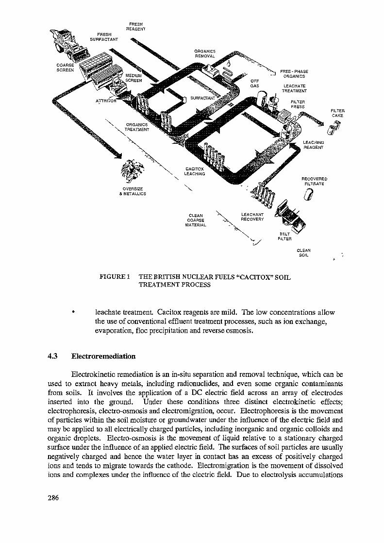
FREE - PHASEORGANICS
RECOVEREDFILTRATE
OVERSIZE& METALUCS
CLEAN "X LEACHANT•V RECOVERYCOARSE
MATERIAL
CLEANSOIL
FIGURE 1 THE BRITISH NUCLEAR FUELS "CACITOX" SOILTREATMENT PROCESS
leachate treatment. Cacitox reagents are mild. The low concentrations allowthe use of conventional effluent treatment processes, such as ion exchange,evaporation, floe precipitation and reverse osmosis.
43 Electroremediation
Electrokinetic remediation is an in-situ separation and removal technique, which can beused to extract heavy metals, including radionuclides, and even some organic contaminantsfrom soils. It involves the application of a DC electric field across an array of electrodesinserted into the ground. Under these conditions three distinct electrokinetic effects;electrophoresis, electro-osmosis and electromigration, occur. Electrophoresis is the movementof particles within the soil moisture or groundwater under the influence of the electric field andmay be applied to all electrically charged particles, including inorganic and organic colloids andorganic droplets. Electro-osmosis is the movement of liquid relative to a stationary chargedsurface under the influence of an applied electric field. The surfaces of soil particles are usuallynegatively charged and hence the water layer in contact has an excess of positively chargedions and tends to migrate towards the cathode. Electromigration is the movement of dissolvedions and complexes under the influence of the electric field. Due to electrolysis accumulations
286
of cations and anions occur respectively at the cathodes and anodes. In addition, watersplitting electrolytic reactions also occur at these electrodes. Thus to ensure that the processescontinue the pH in the system has to be controlled and the contaminants removed.
The concept of electroremediation is currently being extended in the UK, utilising acontinuous electrochemical ion exchange plant with both cathodic and anodic exchangers totreat the secondary wastes generated and condition the cathode and anode streams. Thisresults in a much simpler conditioning and extraction plant. It offers the potential for treatingradioactively contaminated soil in-situ with very substantial reductions in waste volumes ascompared to soil removal and disposal options. It also offers the potential for treatingcontaminated soil under leaking storage areas and buildings without the need for costlyexcavations and even demolition. The technique also has potential for preventing the spread ofplumes of radioactive contamination from old disposal sites, etc. by an electro-fencingapproach.
REFERENCES
[1] DRURY, N. C. Remediation and restoration of a thorium and radium contaminated site.International Symposium on Remediation and Restoration of Radioactive-contaminated Sitesin Europe. 11-15 October, 1993. Antwerp Belgium. Commission of the EuropeanCommunities.
[2] FELLINGHAM, L. R., MAY, N. A. and SNOOKS, W. A. The characterisation andremediation of radiological contamination at the Southern Storage Area, Harwell, England.Second International Symposium on Environmental Contamination in Central and EasternEurope. 20-23 September, 1994. Budapest, Hungary.
[3] TECHNICAL ASSESSMENT GROUP. Rehabilitation of Former Nuclear Test Sites inAustralia. Department of Primary Industries and Energy, Australian Government PublishingService, 1990.
[4] BRCERLEY, K. The British Nuclear Fuels "Cacitox" soil treatment process.SPECTRUM 1992 meeting on Nuclear and Hazardous Waste Management, Boise, Idaho,USA.
[5] PEARL, M., MARTIN, I. and BARDOS, R. P. Using separation processes from themineral processing industry as enabling technology for soil treatment. First InternationalConference of the NATO/CCMS Pilot Study on 'Demonstration of Remedial ActionTechnologies for Contaminated Land and Groundwater', Phase n. 19-23 October 1992,Budapest, Hungary.
[6] AWC Inc. Johnston Atoll TRU soil clean-up project Assembly and demonstration of the"TRUclean" soil clean-up plant. AWC, Las Vegas, Nevada, USA, August 1989.
287
CONCLUSION
PROBLEMS (ENCOUNTERED AND FORESEEN) IN RELATION TO THE PROJECT
Site specifications
Siting and specification of radioactively contaminated sites in CEE is probably the mostdifficult problem in relation to the project The IAEA has a good knowledge of the location of mines,mill tailing sites, areas connected to nuclear plants, larger waste repositories and so forth. However,dumping of radioactive wastes in connection with other industries, as the military and hospitals havedone in some areas, has been done extensively. This has been done without any registrationinformation being given regarding either the sites or the quantity and character of the waste. TheIAEA hopes that the co-operation between it and the member countries in CEE will take on anotherphase so that the environmental restoration programme can start as soon as possible.
The data available is not only incomplete but also somewhat questionable. Estimates fromNon Governmental Organization (NGOs) are often overestimates of the problem. Conversely, figuresprovided by the governments can be underestimates. Not only is there little information but the dataavailable is in many cases inaccurate or questionable. The data presented in some cases may thereforebe either obsolete, incomplete or erroneous, even though the best available sources have beensurveyed. A premise for the environmental restoration project must be the availability of sourcesreferring to and characterizing radioactively contaminated sites, otherwise the efforts and resources putinto the process are useless.
Human resources
From a policy implementation standpoint the political change that has swept the region hasproduced a number of side effects. The on-going change has led to a stall in most of the actions thatthe governmental institutions perform, or aprioritization to a narrower aspect of the governmental dutyspectrum. The somewhat rapid change of government officials does not make co-operation easier.Another problem in this reconstruction of governments has been that the body in charge of importantaspects of waste management is dissolved and that its responsibilities have not been replaced.Previously it was clearer who was in charge of issues relating to the realm of waste management.
Increasing differences among the CEE countries
Due to fee individualization of the former communist countries it is imperative that the IAEAtake action as soon as possible. These countries were brought into the contamination problemstogether and should come out of it together as well. A large co-ordinated project is likely to be morecost efficient and beneficial for the region that separate programmes. Nevertheless, there aretendencies that these countries will go different ways due to among other factors dissimilarities in thenature of their present economic and political objectives. This is a tendency that is not beneficial inthe realm of environmental restoration projects. Close geographical proximity, political structure, andthe similar character of the waste, call for co-operation and the use of the same technology andexperience.
Attitude
Another problem with this project is the governmental, scientific and public view of theproblem of radioactive waste. Since radioactively contaminated substances have been around fornearly fifty years and bad practices in the handling of the material have unfortunately been shown tobe the rule, the public has often accepted that it has radioactive waste around them. It should also bementioned that the public in many, if not most, cases did not know that these substances were in suchclose proximity to their neighbourhoods. This apathetic attitude is fortunately about to change as
289
people in the CEE countries get to know more about such hazardous waste. This may be helpful inthe IAEA's work in identifying such sites.
The different governments often have not been successful in planning and managing clean-upor restoration of contaminated areas. If this attitude persists, the environmental restoration of theseareas will be hard to accomplish.
Another group in society that has an attitude problem regarding radwaste is the scientificcommunity. As the 1992 International Symposium on Environmental Contamination in Central andEastern Europe demonstrated, the subject of radioactive contamination was surprisingly of very littleinterest to the scientists from the contaminated countries. Radiological problems are not perceived bysome as a real issue in the region. This might make the location and surveying of the prospective sitesmore difficult. There is no doubt that the expertise to deal with the problem is present, but thewillingness to deal with the issue may not be there.
Funding and infrastructure
The most severe problem with this project is the lack of financial resources that the CEEcountries have. Given the fact that many CEE countries are in difficult financial conditions, thepriorities that are made are carefully worked out in order to make the best use of available resources.Only that which is considered most important is funded. As our work has shown so far, the severityin both the quantity and quality of the radwaste is so acute that remediation and restoration of theseareas must be among the priorities these countries set. Some countries have, unfortunately, not fullyrecognized this and therefore are not willing to pay for the restoration. An option might therefore beto find countries willing to fund such a project. Some restoration projects have already started,independent of this project, and others are set to start. However, these projects are of a smaller scaleand with a very limited targeted area. A co-operative project, if well planned, is more likely tosucceed than a smaller operation.
A premise for a successful clean-up is to have facilities that can dispose of the generatedwaste. As of today, such facilities are few. The management of very low level waste is even aproblem in the Russian Federation. It is therefore important to look at the aspect of storage/processingsites before the remediation process starts.
Duplication of assistance
The IAEA is not the only organization that seeks to assist the CEE countries in the area ofenvironmental restoration. Rather, many institutions and companies have looked into the issue froman aid perspective (foreign governments) or from a profit perspective (private enterprises). In generalterms, these efforts can be said to be independent of each other and are not part of a general andsystematic plan. This lack of co-operation leaves room for duplication and inefficiency of the efforts.The ideal situation would be a close joint participation between the different institutions taking partin he restoration so that the resources made available would be used more effectively. Also, thecountries that otherwise would not have been able to gain from the acquired knowledge would be ableto do so. One can get the impression that most efforts directed toward CEE are isolated projects.These are not to be disputed if part of a larger plan, but it makes little sense for two organizations torun similar projects in the same area independently of each other.
290
LIST OF PARTICIPANTS
Belarus
Sharovarov G.
Bulgaria
Dimitrov M,K.
Vapirev E.
Canada
Pollock R.
Witehead W.
Croatia
Saler A.
Czech Republic
Andel P.
Pfiban V.
Estonia
Putnik H.
France
Besnus F.
Camus H.
Daroussin J.L.
Germany
Ettenhuber E.
Lange G.
Hungary
Berci K.
Juhasz L.
Italy
Cochi C.
Institute of Radioecology, Academy of Sciences, Minsk
Nuclear Power Plant Kozloduy
University of Sofia, Sofia
Atomic Energy of Canada, Ltd., (AECL), Gloucester, Ontario
Atomic Energy Control Board, Ottawa, (AECB), Ontario
Hazardous Waste Management Agency, Zagreb
MEGA - Institute for Research and Development, Ulnaf ska
MEGA - Institute for Research and Development, Ulnafska
Meteorological and Hydrological Institute, Tallin
Institute de Protection et de Surete Nucleaire (IPSN) -Departement de Protection de FEnvironment et des Installations,Fontenay-aux-Roses
Institute de Protection et de Surete Nucleaire (IPSN) -Departement de Protection de I'Environment et des Installations,Fontenay-aux-Roses
Compagnie General des Matieres Nucleaires (COGEMA), VelizyCedex
Federal Office for Radiation Protection, Berlin
Wisrnut, GmbH, Chemnitz
EROTERV - Power Engineering and Contractor Co, Budapest
National Research Institute for Radiobiology and Radiohygiene,Budapest
Ente per le Nuove tecnologie, 1'Energia e 1'Ambiente, (ENEA), Rome
291
Kazakhstan
Dzhunusov A.K.
Poland
Piestrzynski A.
Romania
Sandru P.
Sandor G.
Russian Federation
Nechaev A.
Slovakia
Slavik O.
Slovenia
Krizman M.
Logar Z.
Spain
Perez Estevez C.
Sanchez Delgado M.
Sweden
Ehdwall H.
Sundblad B.
Ukraine
Rudy C.
United Kingdom
Fellingham L.
Moreton A.
United States of America
Dempsey G.D.
Purdy C.
Westerbeck G.W.
292
Atomic Energy Agency, Almaty
University of Krakow, Krakow
Institute of Atomic Physics, Bucharest
Research Laboratory for Radioprotection, Working Conditionsand Ecology, Bucharest
St. Petersburg Institute of Tehcnology, St. Petersburg
Nuclear Power Plant Research Institute, Trnava
Joseph Stefan Institute, Ljubljana
Rudnik Zirovski VRH, Gorenja vas
Empresa Nacional de Residues Radiactivos, S.A. (ENRESA), Madrid
Empresa Nacional de la Ingenieria y Tecnologia (INITEC), Madrid
Radiation Protection Institute, Stockholm
Studsvik Eco and Safety, Nykoping
Ministry of Environment, Kiev
AEA Technology, Didcot, Oxfordshire
AEA Technology, Didcot, Oxfordshire
Environmental Protection Agency, Washington, D.C.
Department of Energy, Washington, D.C.
Department of Energy, Washington, D.C.
«*•oIDW
Related Documents