PLAN FOR AN ELECTROMAGNETIC SURVEY ON NICKEL MINE HILL SULPHIDE BODY, DRACUT, MASS. by STEPHEN RICE PHELAN Submitted in partial fulfillment of the requirement for the Degree of Bachelor of Science from the Massachusetts Institute of Technology 1934 I Signature of Author:/ Signature of Staff Member in Charge of Research: I

Welcome message from author
This document is posted to help you gain knowledge. Please leave a comment to let me know what you think about it! Share it to your friends and learn new things together.
Transcript
PLAN FOR AN ELECTROMAGNETIC SURVEY
ON NICKEL MINE HILL SULPHIDE BODY,
DRACUT, MASS.
by
STEPHEN RICE PHELAN
Submitted in partial fulfillment
of the requirement for the
Degree of Bachelor of Science
from the
Massachusetts Institute of Technology
1934
I
Signature of Author:/
Signature of Staff Member
in Charge of Research:
I

i
TABLE OF CONTENTS
Page
Acknowledgments . . . . . . . . . . . . . . . . . 1
Object . . . . . . . . . . . . . . . . . . . . . . . 2
Introduction . . . . . . . . . . . . . . . . . . . . 3
Summary . . . . . . . . . . . . . . . . . . . . . . 4
I. SELECTION OF THE SITE OF THE SURVEY . . . . . . 5
Type of Area Sought ............. 5
Suitability of Other Methods . . . . . . . . . 5
Determination of the Conductivity of the Ore
and Surrounding Rock.... ....... 6
Previous Work - Shafts, Prospects and Outcrops
at Nickel Mine Hill . ........ .. 7
Outline of Work ........ ...... 8
General Geology of Nickel Mine Hill . . . . . . 8
Remarks on Geology Pertinent to Prospecting . . 11
Reconnaissance Geology . . . ..... . . . . 12
Reconnaissance and Mapping of North Shear
Zone . . . . . . . . . . . . . .. 12
Reconnaissance of Open-Cut Outcrop . . . . 14
Elimination of Unsuitable Areas . . . . . 17
Surface Prospecting ........... 17
Dip Needle Line ......... 17
Power Line Interference . . . . . . . . . 19
Conclusions . . . . . . . . . . . . . . . 19
I9GG G ()

ii
TABLE OF CONTENTS (continued)
Page
Character and Distribution of Sulphides
Pyrrhotite . . . . . . . . . . .
Minerals of Open-Cut . . . .
Secondary Minerals . . . . . .
Theories of Sulphide Deposition
Layout of the Loop and Transit Survey
Layout of the Loop . . . . . . .
Base Line of Transit Survey . .
Accuracy of Transit Survey . .
Checking . . . . * . . . . . .
Plan of Transit Survey . . . .
II. THE TWO-FRAME SURVEY . . . * . *
Principles of the Electromagnetic
Basic Advantages . . . . .
Application . . . . . . .
. . . .
. . . . 21
. . . . 22
. . . . 22
. . . . 22
. . . . 22
. . . . 23
. . . . 25
. . . . 25
. . . . 26
Methods
. .0
. .0
* 0 6 0 0 6
* a a a a 0
Theory of Electromagnetic Methods .
Classification of Electromagnetic Methods
Detection of Resultant Field . . . . .
Two-Frame Method . . . . . . . . . .
Errors Using a Single Coil . . . . . .
Errors in Two-Frame Method . . . . . .
Procedure in Taking Two-Frame Readings . .
Readings along Lines . . . . . . . . .
Phase Shift - Orebody Direction . . .
20
20
27
27
27
27
28
33
35
35
36
39
39
39
40
. . .

iii
TABLE OF CONTENTS (continued)
Further Information . . . . . .
Scale of Plotted Results . .
Procedure . . . . . . . . . . . .
Frame Constant .
Layout of Survey Plan . .
Frame Technique . . . . . . .
Angle E ....... ....
Angles 0oij and 0(2' ' * *
Angle dS . . . . . . . . ..
Vector Explanation of Angles
Interpretation of Curves . . . .
Curves Obtained . . . . . . .
Calculation of Normal Vertical Field
Approximate Method .
Description of Apparatus .
Summary of Work Done . .
Conclusions . . . . . .
III. SUGGESTIONS FOR FURTHER WORK
Mapping of Schlieren . .
Survey of Related Areas
Pneumotectic Deposit . .
Cobalt and Platinum . .
Dip-Needle and Magnetometer
* * . .
* . a *
* a a a
* a a
* 0 0 S
* a * a
* * a a
* a a a
* 0 a a
* 0 6 0
* a a a
. . . . . . . 0 .
. . . . . . . . .
. . . . . . . . .0
. . a 0 . . . 0 .0
. 0 0 . . . . . .a
. . . . . . a a .
0 . 0 . . . a a .
. . a a . 0 . . .0
. . . a . a . . .a
40
41
41
41
41
41
42
42
42
42
43
43
45
45
48
48
49
50
50
50
50
51
. 0 . . 0 . . . 51

iv
TABLE OF CONTENTS (continued)
Page
IV. BIBLIOGRAPHY . . . . . . . .
Geology . . . . . . . .
Mining . . . . . . . . .
Electromagnetic Method .
V. APPENDIX A -MAPS I to IV . .
. . . . . . . . 52
. . . . . . . . 52
. . . . 0 0 0 . 53. 0 . . . . 0 . 53
. 0 . 0 0 0 . 0 55
V
LIST OF ILLUSTRATIONS
Figure Page
1. Rock Outcrop behind Quarry . . . . . . . . . 10
2. Open-Cut Outcrop . . . . . . . . . . . . . . 10
3. Dip-Needle Traverse across Open-Cut . . . . . 18
4. Loop Layout and Transit Survey . . . . . . . 24
5. Electromagnetic Field around a Flow of Current 29
6. Secondary Current Flow Induced in Conducting
Bodies by Primary Field . . . . . . . . 30
7. Diagrams of Horizontal Components of the
Electromagnetic Field . . . . . . . . . 31
8. Profile Illustrating Change in Vertical and
Horizontal Components . . . . . . . . . 32
9. Vector Resultant Field . . . . . . . . . . . 38
10. Angle 6 . . . . . . . . . . . . . . . . . . 38
11. Angles 1CII and oC 2 * * * * * * * * * * 38
12. Angle C . . . . . . . . . . . . . . . . . . 38
13. Two-Frame Inductive Curves over a Railroad
Track at Buchans, Newfoundland . . . . . 44
14. Calculation of Normal Vertical Field outside
a Loop 900 feet by 300 feet . . . . . . 46
15. Calculation of Normal Vertical Field outside
a Loop 900 feet by 300 feet, Approximate
Method . . . . . . . . . . . . . . . . . 47

vi
MAPS IN APPENDIX OF THESIS
Page
56
57
58
I. Topographic Map, Showing Nickel Mine Hill
and Surrounding Area . . . . . ... . . . .
II. Geological Map of Nickel Mine Hill . . . .
III. Large Topographic Map of Nickel Mine Hill,
Showing Workings, Sulphide Outcrops, and
Shear . . . . . . . . . . . . . . . . . . .
IV. Small Topographic Map of Nickel Mine Hill to
Show Topographic Features . . . . . . . .
Number
59

1
ACKNOWLEDGMENT S
The author wishes to render thanks to
Professor F. L. Foster, in charge of this thesis,
for a ready willingness to give advice. Professor
R. G. Hudson furnished appreciated encouragement.
The geological part of this work would have been
much less clear but for the help of Professor F. K.
Morris. Other expert advice was received from
Professor W. H. Newhouse and Professor A. C. Lane
(of Tufts). He also wishes to thank the various
students, among them, C. A. Price, a second-year
mining student, and Leonidas Keolyos, a senior
electrical student, for assistance rendered in the
field.
2
OBJECT
The purposes of this survey were: (1) to
learn the technique of the Two-Frame method of
electromagnetic prospecting by application of the
method to a pyrrhotite outcrop at Dracut, Mass.;
(2) to apply geological principles as much as
possible to the electromagnetic survey of the
area.

3
INTRODUCTION
The remark is often made that the successful
miner is not the man who strikes ore, but rather the man
who knows just when to quit. If the electromagnetic survey
is considered in much the same light, it can be a great aid.
The author believes as much is gained by choice of a
proper area, geologically speaking, as by much interpreta-
tion of electrical data gained there. If, upon applica-
tion of his structural geology, one can decide on no
particular area, he should discard the survey of that
region entirely. Mr. Hans Lundberg, influential in the
development of electromagnetic methods, is of the same
opinion regarding the geological preparation.
It is certain, therefore, that the interpreta-
tion geologically is just as important with regard to the
eventual electrical results as is the proper interpreta-
tion after the field procedure. Disturbing bodies are
eliminated as much as possible from the start. The trend,
also, of the geological formation must always be correlated
with the readings as the work progresses.
4
SUMMARY
The author felt, from his experiences in
prospecting work, that much unnecessary effort could be
saved by a union of electromagnetic and geological recon-
naissance. There is, at present, not sufficient harmony
between the two methods of attack, but a proper background
of geological field technique can as well direct, as aid,
in the interpretation of geophysical results. This work,
therefore, consists of applications of geological recon-
naissance and of the electromagnetic method.
The mere term t anomaly' means an unusual
response due to a disturbing orebody or zone. Properly,
one can form laboratory analogies of anomalies in the
field by use of so-called "synthetic" orebodies, as metal-
lic masses covered with earth or salt water. The response
of a given formation to the electromagnetic method is
rarely dependent on a single mineralized zone, but rather
on many such zones, and particularly on water. This
thesis sets up a plan for applying such an electrical
survey in a suitable area.

5
I. SELECTION OF THE SITE OF THE SURVEY
Type of Area Sought. Due to interference by
trolley and power lines, it was deemed inadvisable to
attempt geophysical work around Cambridge. An area of
mineralization in which would be duplicated conditions of
a region successfully prospected by this method was sought.
After some trouble in this regard, Professor W. H. New-
house suggested the Dracut pyrrhotite body. This region,
in many respects similar to Sudbury, Ont., which yielded
fine results to electromagnetic work, has proved a suitable
as well as stimulating project. The location of Nickel
Mine Hill is shown on Map 1.
Suitability of Other Methods. The author be-
lieves, as a result of dip needle work, that the magneto-
meter, or even dip needle, could give good indication at
Dracut. The ore is highly permeable. It is doubtful
whether or not the presence of pyrrhotite in small quan-
tities throughout the norite and of small pyroxenite
masses would not interrupt the indications from massive
sulphides. The magnetic method is preferable from the
point of view of simplicity, cost and effort, while the
electromagnetic is more accurate. The wisest course in

6
such a case is to check up the magnetic with the electro-
magnetic survey. A possible application of the equipo-
tential method could be found by determining the outline
of the orebodies under the glacial debris to the north,
east, and west of the open cut; for, in cases of soil cover,
such as here, the equipotential method is equally effective.
Determination of the Conductivity of Sulphides
and Surrounding Rock. Beyond the self-evident low re-
sistivity of the massive sulphides, the resistivities of
other samples of rock and sulphides were tested. The
method used was a simple Wheatstone Bridge method with
galvanometer and direct current. The results are suffi-
cient for estimation of the following resistivities:
Massive ore - About one ohm per cubic centimeter.
Mixed norite and sulphides (gradation from massive
to normal norite)-about 200,000 ohms per cubic
centimeter.
Normal norite - Several million ohms per cubic
centimeter.
The massive ore, therefore, is an excellent
conductor in comparison with the norite. The small
amount of sulphides disseminated throughout the normal
norite gives it no extraordinary resistivity value.

7
Previous Work1 - Shafts, Prospects and Sulphide Outcrops
The following are shown on Map III: (a) open-
cut; (b) 61-foot shaft; (c) small shaft, and prospects.
It may be surmised, therefore, that since discovery some
development work has been done. It is possible that the
deposit was worked as long ago as 1640, certainly before
1710 . In 1726, the property was supposed to have yielded
gold and silver. During the Revolution the shaft was
sunk, it is said, to a depth of 43 feet. The first attempt
to recover nickel was made by a company in 1876 - the
shaft was continued down to its greatest depth, 61 feet.
Again, in 1883, the mine was worked. Accompanying the
latter operations was a small stamp milling plant in 1876
and a small furnace smelting plant in 1883. Iron, nickel
and cobalt were obtained by a chlorination roasting with
salt. A crushed stone quarry, 1923, shown on the map,
encountered sulphides in its operations.
It seems certain, therefore, that all three
classes of workings date from the recent development work,
for the workings would have fallen in completely by this
far date. Perhaps the open-cut, however, is much older.
1Bibliography II-1, pp. 20, 35; Bibliography 1-3.
2Bibliography I3.

8
The repeated attempts at working, though commercially un-
successful, the small recovery plants, the presence of an
old road, lend a slight possibility to a renewal of opera-
tion in case of extended discoveries.
Outline of Work
The plan of work to be undertaken was:
(1) Sufficient geological reconnaissance and Two-Frame
readings to understand the sulphide distribution;
(2) Geological prospecting about the open-cut area;
(5) Brushing and laying out of loop and transit lines;
(4) Rehearsals of Two-Frame Methed;
(5) Actual application of the method to the sulphide body.
General Geology of Nickel Mine Hill
To understand the proven principles of sulphide
formation at Dracut, it is well to recall that the norite
stock is post-Cambrian in type. A study of such an outcrop
(Fig. 1) as occurs near the contact of the norite and the
Merrimac quartzite behind the quarry (outcrop marked on
Map II) explains the principal types of rock found. These
9
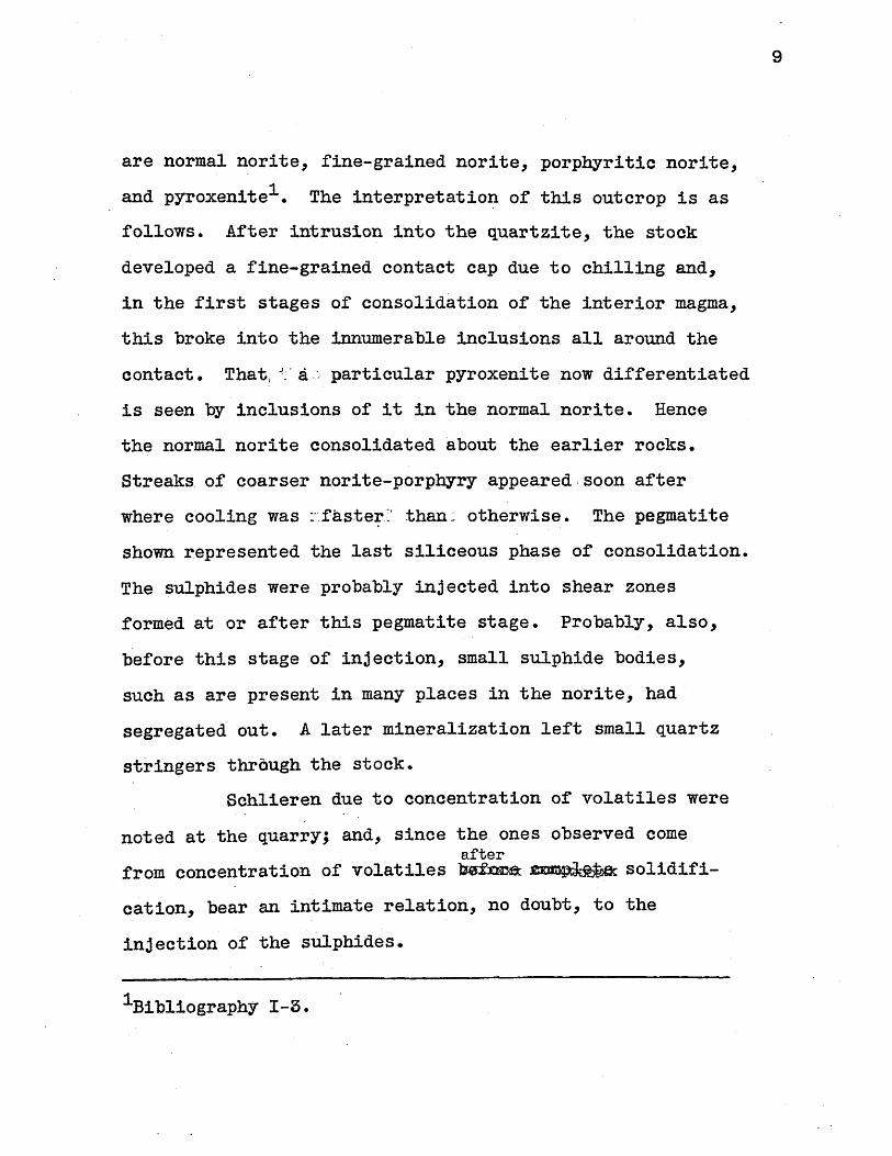
are normal norite, fine-grained norite, porphyritic norite,
and pyroxenitel. The interpretation of this outcrop is as
follows. After intrusion into the quartzite, the stock
developed a fine-grained contact cap due to chilling and,
in the first stages of consolidation of the interior magma,
this broke into the innumerable inclusions all around the
contact. That, § A: particular pyroxenite now differentiated
is seen by inclusions of it in the normal norite. Hence
the normal norite consolidated about the earlier rocks.
Streaks of coarser norite-porphyry appeared.soon after
where cooling was :faster? than: otherwise. The pegmatite
shown represented the last siliceous phase of consolidation.
The sulphides were probably injected into shear zones
formed at or after this pegmatite stage. Probably, also,
before this stage of injection, small sulphide bodies,
such as are present in many places in the norite, had
segregated out. A later mineralization left small quartz
stringers thraugh the stock.
Schlieren due to concentration of volatiles were
noted at the quarry; and, since the ones observed comeafter
from concentration of volatiles befnne zmmvbtAe solidifi-
cation, bear an intimate relation, no doubt, to the
injection of the sulphides.
1Bibliography I-3.

10
41
4)
/
-qahro, or norte
pyegorenitc, Inc/Uxvons
fCIVpcir- peqMncit/te
Yarbbr-O-po.-Phy rItic
bY'ne-qrc71ned CO tCzc I9qc6P-o
5Ff ,J
OU&PfcOp bc'A/,,Q Quarry
MVW
-pyrrk~oier 6*dy
4-n orvite
/h 0f'jTe
Fi 9. 2, Open COu Iro
s
orA 7S ~- Of-.--
Oulcr-Op

11
The Dracut. norite is intruded into the Merrimac
quartzite, of probable Cambrian age, and is intruded by
the Andover granite, of Carboniferous or post-Carboniferous
age. Its age, therefore, ranges from Cambrian to Permian.
Since all the rocks of the area (their geology is given in
Map II) but norite have suffered regional metamorphism,
the norite must be later than the last period of deforma-
tion, or Pennsylvanian. Triassic faulting probably
affected the stock.
Remarks on Geology Pertinent to Prospecting
The field work in preparation for the survey -
consisting principally in the proper estimating of the
strike of the mineralized zone - was productive of
gratifying results.
The authort s geological observations were con-
fined to the deposition of the ores. He believes that
valid evidence uncovered points to quite an extensive
zone of mineralization for delimitation by the electro-
magnetic survey. It is fortunate from the geophysicist's
point of view that few geologists in their reconnaissances
of unimportant areas can spare the time to investigate
more than the conditions of ore deposition. The scientific
12
prospector must approach the area with an attitude, it is
true, for applying general principles of geology, but he
must be attentive, above all, to the development aspects
of the deposit.
Reconnaissance Geology
Reconnaissance and Mapping of North Shear Zone.
The first day's work consisted of a general reconnaissance
of the norite stock, and plane-table mapping of a significart
shear zone. The problem was approached from a prospector's
point of view, since, beyond general directions as to the
location of the norite, no information had been gained by
the author and assistant. The -stock was located after a
consideration of the topography, but unfortunately the
pyrrhotite body was not found on that day. Professor
A. C. Lane, a few days after, kindly indicated on a map
the old mine, hidden away about 500 yards from our pre-
vious plane-table station.
The finding, however, of traces of an old road
some time previous had led the author to believe that the
pyrrhotite was not far away; and for future reference
certain very evident shears and quartz stringers were
mapped. No doubt, such short reasoning from topographic
13
expression is not generally justified: the true prospector
checks up at every step. But hypotheses are sometimes
better than nothing.
This shear is indicated in red on a large topo-
graphic map (Map III). The strike of the shear points
directly with a series of glaciated gulleys on the north-
west extremity of the stock, then along an evident scarp
into the region of pyrrhotite outcrop. The gulleys, un-
doubtedly, are due to shearing and glaciation, but con-
trary to Burton and Spaldingi, the author does not believe
that faulting of the region has produced a fault scarp
such as they mention. Glaciation has rounded the scarp,
and could well have carved it from a pronounced shear
zone. The quartz stringers the author considers multo-
post and unimportant,.and they are not noted on the map.
As can be seen from the contours, glaciation has produced
a monadnock with the northern toe scoured off; since this
material is deposited on the southern heel, the glaciation
was from the north. In this manner was produced the scarp
adjoining the northern shear zone - not by faulting.fault or *
Several/shear zones noted by Burton and Spalding and the
author have been indicated on Map 1I2 . No general course
1Bibliography, I-1, p. 19.
2Idem.

14
of shearing, beyond that of the northern extremity, can
be gained from this procedure.
Reconnaissance of Open-Cut Outcrop. The next
dayts activity, with more information on the location and
type of deposit, resulted in the finding and examination
of the nickeliferous pyrrhotite exposed in the open-cut.
Here the advisability of considering shear, rather than
schlieren, for extensions of the body was revealed. Ac-
cording to Professor F. K. Morris, the Germans are quite
proficient in demonstrating the flow structure of batho-
liths, stocks, and other intrusive bodies by mapping of
schlieren on an extended scale. A survey of this type
would probably determine much with regard to the trend of
the pyroxenite. Since the pyroxenite bears close associ-
ation with the sulphides at the Key West Mine in Nevada ,
and at the Lancaster Gap Mine2 in Pennsylvania, as well
as in the open-cut , data on the determination of the
trend of the sulphides might result. For the author's
purposes such an extended mapping was impractical.
The reconnaissance proved that shear was asso-
ciated with, and an important condition of, sulphide
deposition.
1Bibliography, I-1, p. 41.
2Bibliography, I-4, p. 803.
3Bibliography, I-1, p. 44.
15
Fairbanks statesi: "A shear zone occurs to the
south of Burns Hill in which the shearing is developed
roughly parallel to the elongation of the stock and along
the strike of the quartzite. The norite of this zone
exhibits flow structure and has been intensely altered
and crushed. Long-drawn--out Isegregationst containing
pyrrhotite and resembling the ore of the mine are abundant
in this zone. In a few places calcite-sulphide veins cut
through the sheared norite, and some patches of actinolite
are found. The shearing produced a readily permeable
zone for the late magmatic mineralizers referred to in
this paper as paulopost." The chief of these minerals
were pentlandite and pyrrhotite2 . The location of Burns
Hill is shown on the Nickel Mine Hill Map, Map II, to-
gether with the location of the open-cut outcrop. They
occur in the same stock and are not far distant. The
above description of the Burns Hill deposit could well be
applied, with the exception of calcite-sulphide veins, to
the open-cut outcrop. Furthermore, more than one outcrop
of pyrrhotite is in the direction of shear (Map III).
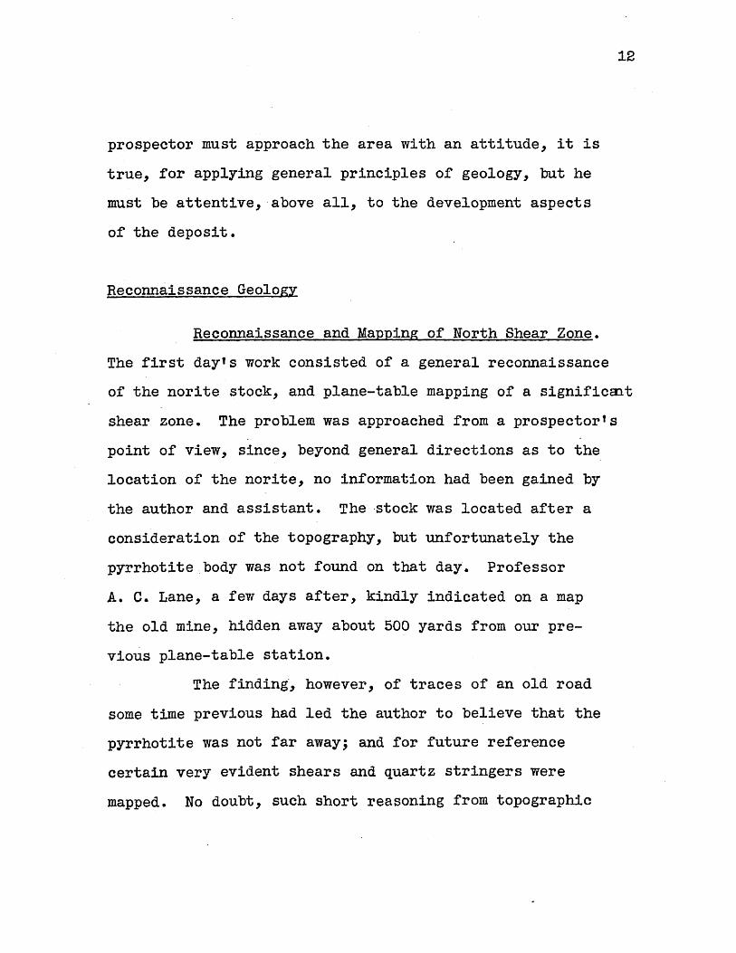
The reconnaissance of the open-cut produced the
sketch given (Fig. 2). The strike of the shear in the
1Bibliography, I-3, p. 403.
2Bibliography, 1-3, p. 408.

16
adjacent rock could not be clearly made -out. The most
important points to notice are (1) comparatively verticalzone
brecciatio/, indicating shear, and, 7 (2) the presencesulphides
of one horse completely surrounded by /:, and of another
not.entirely surrounded. These were noted carefully. In
no way can the author account for *(2)- when he considers
the injected or intrusive nature of the deposit, except by
the obvious explanation that the rock was first sheared,sulphides
then the (/ deposited in the shear zone . Thus correla-
tion with the Burns Hill outcrop is practically perfect.sulphides
What additional / are- found should extend along the
northern shear zone (a rather wide zone) from the open-cut
outcrop; for certainly the vertical, dikelike form of the
sulphides would indicate that the shear in which the sul-
phides formed guided them. Hence, most likely some otheralong
shear /. the northern zone is mineralized. The author is
not able to differentiate the earlier shear of deposition
from later possible shears, but since the vertical bare
rock scarp rises in a straight line, to the south, the
first shear is delimited to a definite zone in general
perpendicular to the strike of the open-cut.
A nearly vertical dip seems indicated, but
whether this is deceptive, as is often the case (witness
1Bibliography, 1-4, pp. 801, 802, 807, 808.

17
gash veins), or how far down the deposit extends in dip,
can be properly turned over to survey.
Elimination of Unsuitable Areas. Advantage was
taken of the physiography (Map IV). It is simple to trace
out the bare rock over whole regions, all of which was
noted on a sketch and immediately discarded from further
consideration. In this way the survey pattern (see Fig. 4)
was laid out. Concerning the low-lying drainage area,
particularly to the northeast, the author makes no state-
ments, for it is under cover and not exposed to view. He
suspects that the comparatively great drainage in the open-
cut and the moist character of the northeast area, particu-
larly after a rain, are due to the shear-zone structure.
Surface Prospecting. The distribution of float
from the pyrrhotite body could not be used as a check on
the zonal distribution of the ore. As stated, the glacier
has gouged out the northern sheared regions; a surface
expression of depression could have been left, but debris
has covered this up. Slopes are too slight for float to
travel far.
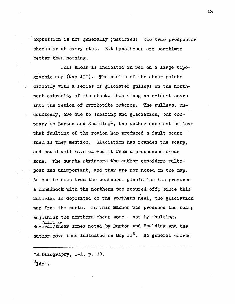
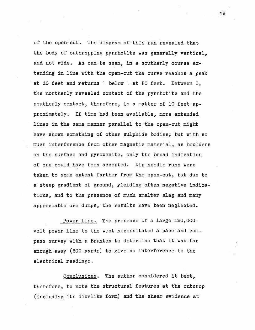
Dip Needle Line. A dip-needle1 line (Fig. 3)
was taken across the outcrop of pyrrhotite, at the head
1Bibliography, II-3.

148
*lr-ct pnm 0 - Cu-c
19
of the open-cut. The diagram of this run revealed that
the body of outcropping pyrrhotite was generally vertical,
and not wide. As can be seen, in a southerly course ex-
tending in line with the open-cut the curve reaches a peak
at 10 feet and returns below . at 20 feet. Between 0,
the northerly revealed contact of the pyrrhotite and the
southerly contact, therefore, is a matter of 10 feet ap-
proximately. If time had been available, more extended
lines in the same manner parallel to the open-cut might
have shown something of other sulphide bodies; but with so
much interference from other magnetic material, as boulders
on the surface and pyroxenite, only the broad indication
of ore could have been accepted. Dip needle runs were
taken to some extent farther from the open-cut, but due to
a steep gradient of ground, yielding often negative indica-
tions, and to the presence of much smelter slag and many
appreciable ore dumps, the results have been neglected.
Power Line. The presence of a large 120,000-
volt power line to the west necessitated a pace and com-
pass survey with a Brunton to determine that it was far
enough away (600 yards) to give no interference to the
electrical readings.
Conclusions. The author considered it best,
therefore, to note the structural features at the outcrop
(including its dikelike form) and the shear evidence at

20
the open-cut walls and in line with it, and, in general,
in laying out the base-line for the survey, to follow along
the line of the shear scarp. He feels certain that more
sulphides will be encountered. Indeed, another small out-west
crop occurs a short distance/towards the north scarp from
the open-cut. What the true dip and strike of the deposit
is, together with its extent, and whether it is accompanied
by others, is left to the electromagnetic field work to
indicate.
Character and Distribution of Sulphides
Pyrrhotite. This mineral composes the great
bulk of the -mineralized zone. It is easily attracted to a
magnet, and able, when drawn near a dip needle, to cause
it to oscillate. The open-cut outcrop contains pyrrhotite
with very little else; but it is found in other places
(prospects and shafts on Map III) in not such massive
occurrence. The massive pyrrhotite at the open-cut, too,
grades into wall rock. It comes, in minute quantity, in
-all types of the gabbro, but in greatest amount in the
coarse pyroxenite and in the fine-grained rock similar in
composition. The pyrrhotite is often found in connection
with pyroxenite. Even the stock itself contains some small
amount of pyrrhotitel. Due to the fact that the pyrrhotite
1Bibliography, I-I, pp. 34, 36, 43.

21
has been found to replace gangue mineral, it has been
placed in the paulopost period in the norite's consolida-
tion historyi.
Minerals of Open-Cut. The open-cut minerals
are listed as follows by Fairbanks:
Magmatic
Magnetite
Olivine
Augite
Hypersthene
Plagioclase
Paulopost
Basaltic hornblende
Pentlandite
Pyrrhotite
Biotite
Serpentine
Actinolite
Unknown
Multopost
Marcasite
"Polydymite"
(undetermined)
Limonite
The nickel in the sulphides, undoubtedly, is
due to the'pentlandite. The analyses of Burton and
Spalding showed a small percentage of nickel in the mine
sulphides, about one per cent 3, and they concluded that
ordinary fine crushing and Wilfley table separation was
as good a method of separation as any4. Platinum, as at
5Sudbury, could appear in traces
Bibliography,2Bibliography,
3Bibliography,4Bibliography,5Bibliography,
I-3, p. 411.
1-4, pp. 799, 801, 870.
II-1, p. 67.
11-1, p. 70.
I-3.

22
Secondary Minerals. A really close examination
of the Hill was first made by Fairbanks in 1912. No doubt
the secondary mineralization that he found has been guided
by the shearing in much the same way as the paulopost
mineralization. It is important to note that these
minerals were overlooked before. Chalcopyrite and other
sulphides, in the so-called calcite-sulphide veins, occur
in a zone of shearing on the northern edge of the stock.
But, it must be noted, this secondary or multopost miner-
alization is not in much evidence in the list of open-cut
minerals.
SulphideTheories of ./, Deposition. (a) The ratio of
sulphides/ to norite should be the same as at Sudbury, Ontario .
sulphides(b) The /. occur. in connection with a pyroxenite dike
2 .
The survey should throw some light on these questions, as
well as give some idea of the partial deposition of the
3ores at Sudbury
Layout of the Loop and Transit Survey
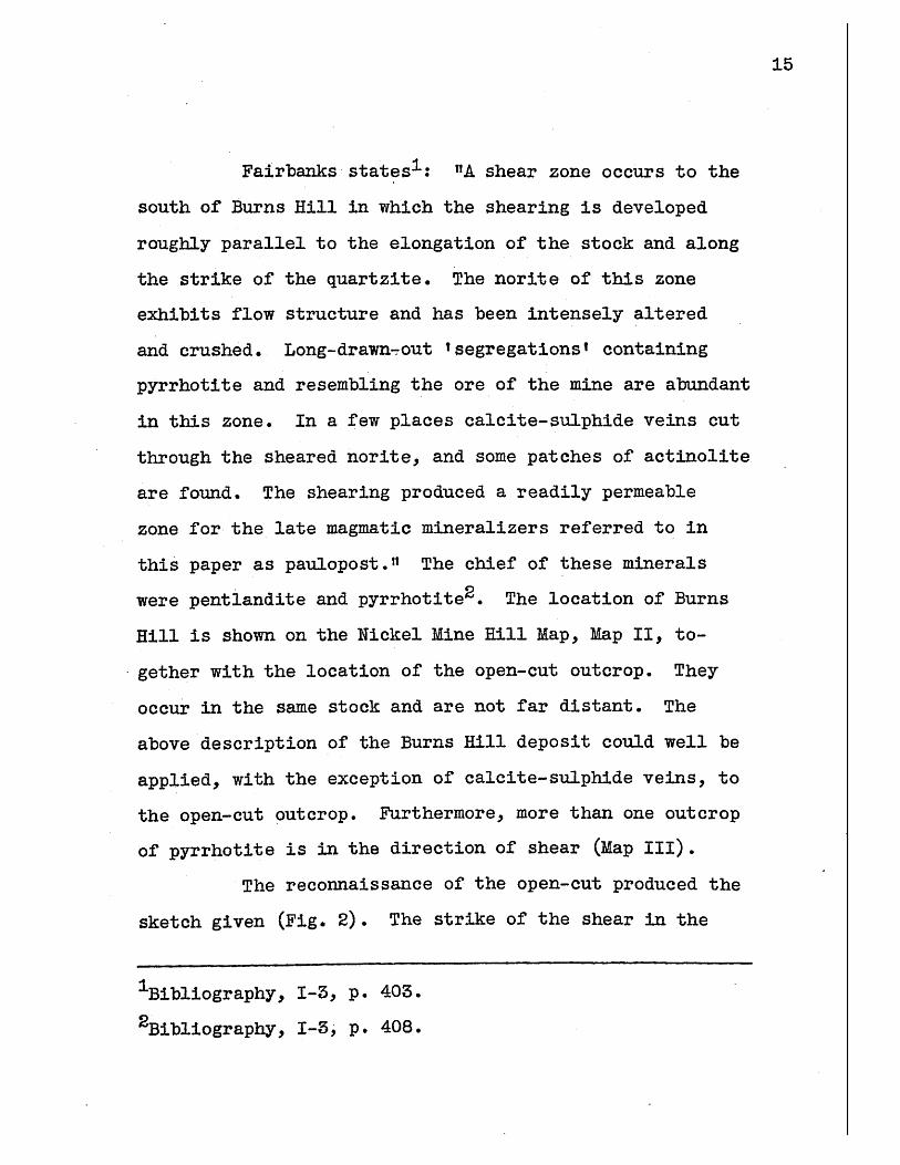
Layout of the Loop. The location of the loop
and the survey plan is given on the large topographical
map (Map III) and the dimensions of the loop and survey
1Bibliography, 1-3.2Bibliography, 1-3.
3Bibliography, 1-4, p. 803.

23
are given in a separate diagram (Fig. 4). Besides these, a
small topographical map (Map IV) of the Nickel Mine Hill
area is included to give a better idea of the topography
as a whole.
Due to lack of wire necessary for a larger loop,
it was decided to use a 300 by 900 foot loop instead of
the standard 3000 by 1500, or 1800 by 450 foot loop. This
necessitated a close study and elimination of unsuitable
ground, that is, reduction of the survey to mineralized
areas. Since, by this time, the strike of the deposit was
quite apparent from reconnaissance work, the undesirable
areas were easily left out of the plan. Topography was an
aid in elimination, for bare rock outcrops to the south of
the base-line shown on the maps. Likewise, the glacial
debris has filled small gouged-out gulleys parallel to,
and near, the expected strike, and it may be surmised
that the shear and oxidation of the ore played a part in
causing them.
Base Line of Transit Survey. The base-line,
therefore, was first of .all laid out along the supposed
line of strike. A plane-table arrangement was used to
approximate a line at right angles to the open-cut, and
equal distances measured along it. When the transit
lines had been decided upon, the transit base line was
run along this first one in order to provide a check on

Q)
z
open-cut fine
1111f It oo
,-300'
SIcale: 1 inch = fOO ft
Loop Layout anld Transit Survey
25
the work. The arrangement and distances of this survey
are given in the plan diagram. Especial care was taken
that the angles checked, but not such close attention was
given to the taping of distances.
Accuracy of Transit Survey. A discussion of
the accuracy of this survey might be included, but is
comparatively unimportant. To begin with, the accuracy
of such a survey need not be very great, not even so much
as that of an ordinary land survey, because other sources
of error are present. The errors resulting from departure
of the horizontal frame from a horizontal position alone,
errors in locating and reading null points, variations of
the note of the buzzer with consequent audible trouble in
the headphones, far overshadow those due to the geometry
of the layout. Here it is to be noticed that a large
number of errors, such as variation in frequency of the
buzzer, are eliminated from the ratio nature of the read-
ings along the lines.
Checking. Undoubtedly the transit work was suf-
ficiently precise, for closure on station lines usually
checked to within a few feet, and angles to within a few
minutes. The last line to the west, however, was laid off
incorrectly due to steepness of topography, and will have

26
to be lined in with a Brunton, taking as a reference the'
near side of the loop. This loop line has been well-
checked.
Plan of Transit Survey. As stated, the base-
line was run out at approximately right angles to the
open-cut. Equal distances (see Fig. 4) of a hundred feet
were measured out on it from the survey point. This con-
sisted of a small stamped cross-mark at the head of the
open-cut, in solid outcrop of ore. Then, by the use of
the brush-hook lines were run out on each side of the
base-line, and station markers put at fifteen-foot inter-
vals. The markers consisted of small wooden stakes,
somewhat smaller. than the base-line stakes.

27
II. THE TWO-FRAME METHOD
Principles of the Electromagnetic Methods
Basic Advantagesi.
(1) Requires no grounded electrodes and is independent
of surface conditions.
(2) Presence of an insulating sandwich layer not detri-
mental to readings.
(3) Water indication is least at low frequencies.
Application. The electromagnetic method is ap-
plicable to ores of suitable conductivity. They are the
native metals, the sulphides (except sphalerite) the
arsenides and the antimonides2. The absence of conductors
other than ore is desirable. Graphitic schists, for
example, cause interference. The texture of an ore, of
course, has an immense effect on its conductivity. A
trial run is the best test of the area. It is to be
noticed that an electromagnetic method is usually both a
reconnaissance and detail method. The best success of
the electromagnetic survey is at depths under 300 feet.
|Bibliography, 111- P. 16.
2Bibliography, 111-3, p. 16.
28
Theory of Electromagnetic Methods. The funda-
mental theory of each of the electromagnetic methods is
the same, namely, that a primary field from a vertical or
horizontal current-excited coil causes. currents in
conduct6rs and that these set up a secondary field that
interacts with the primary field. Anomalies of intensity,
direction and phase are thus produced in the -primary
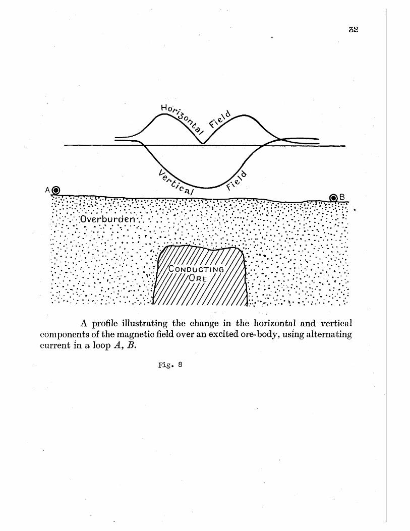
electromagnetic field. See Fig. 9 for vector diagram,
Figs.; 5, 6, 7, and 8 for curves. Usually it is possible
to consider the magnetic vector and neglect the electric
vector, since the permeability of a substance increases
with the conductivity, and far exceeds the conductivity in
effect. The electric vector can be detected.
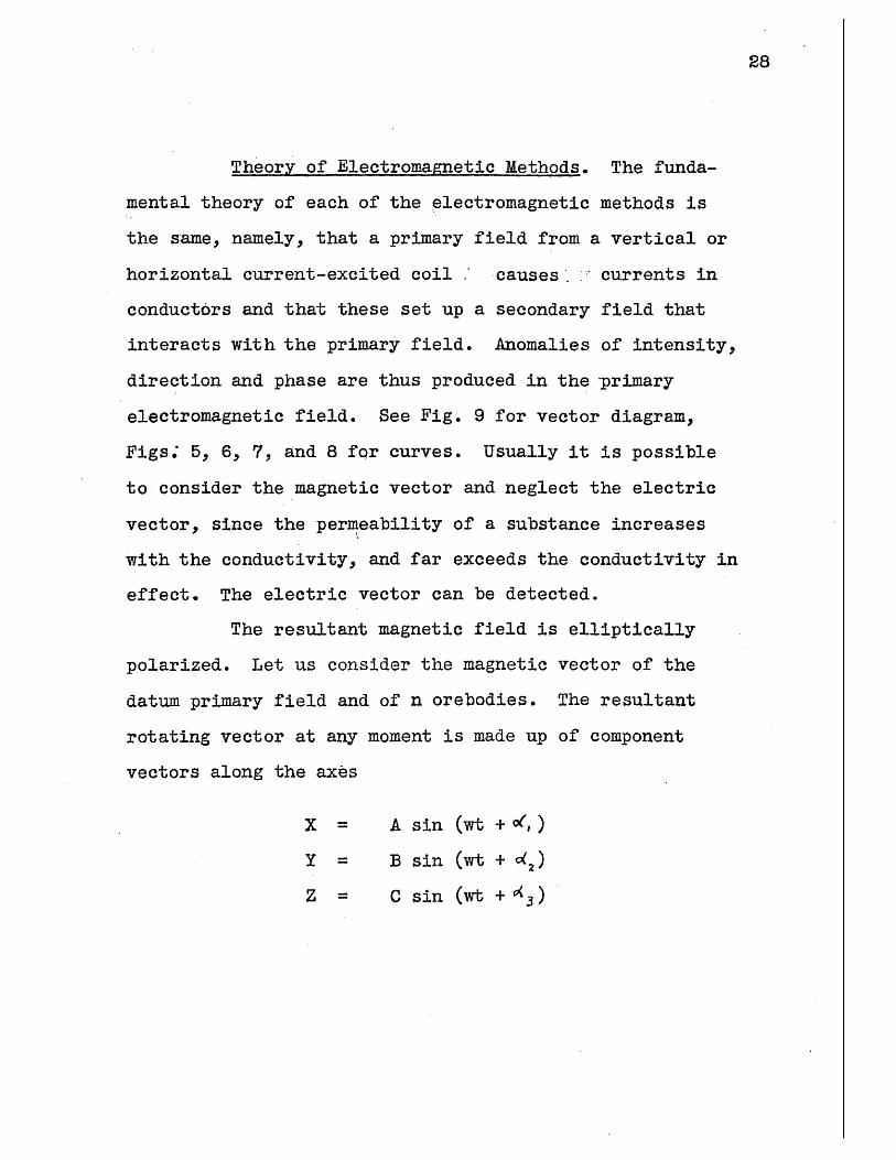
The resultant magnetic field is elliptically
polarized. Let us consider the magnetic vector of the
datum primary field and of n orebodies. The resultant
rotating vector at any moment is made up of component
vectors along the axes
X = A sin (wt + 0,)
Y = B sin (wt + d2)
Z = C sin (wt + ( 3)

29
T
surface v4 /f~i dli
H -
T Tokal FieldH Horizonial componentV :Vertical
N-
H
- Lins of Force of El. M -n.Field
a. Crossection of conductorcarrqing the current-.
d bistance to conductor [romsurface.
ELECTROMAGNETIC FIELD AROUND A FLOW OF CURRENT.
Fig. 5
0

5ection A-ALINES 4 FORCE i
EL. MASM. FiELDS
* * ~'.rA,,rdJa* ~-rA~9'x~t
SECONDARY CURRENT FLOW INDUCED IN CONDUCTING BODIES BY PRIMARYCURRENT IN CABLE.
Fig. 6
30
A

/ I
Datum Ord 5U ce
I b
Datum
I' 7C
. Jb
O Datum
d
e
Boundary Poi
f.
a.b.C.d.e.f.
DIAGRAMS OF HORIZONTAL COMPONENTS OF ELECTROMAGNETIC FIELD.Around concentrated current flowing through orebody.Around current in cable and barren ground.Around current induced in orebody.Around current directly supplied.Actually observed while surveying.Purely caused by orebody.
Fig. 7
31
%I
32
H
A®
Overburden***, ~WjF
*',~* *~ . ~* ** .. ~*~'*:O* N*.UCT * *1
* 9 9 . 9 9 99****9.* ORE~
A proil ilutrtn th chng in th hoiona and vertical' * Z . * ..
compoentsof te maneticfiel ove an xcite orebody usig alenaic
curen in a lo... A, B.. 9 .9
Fig. 8
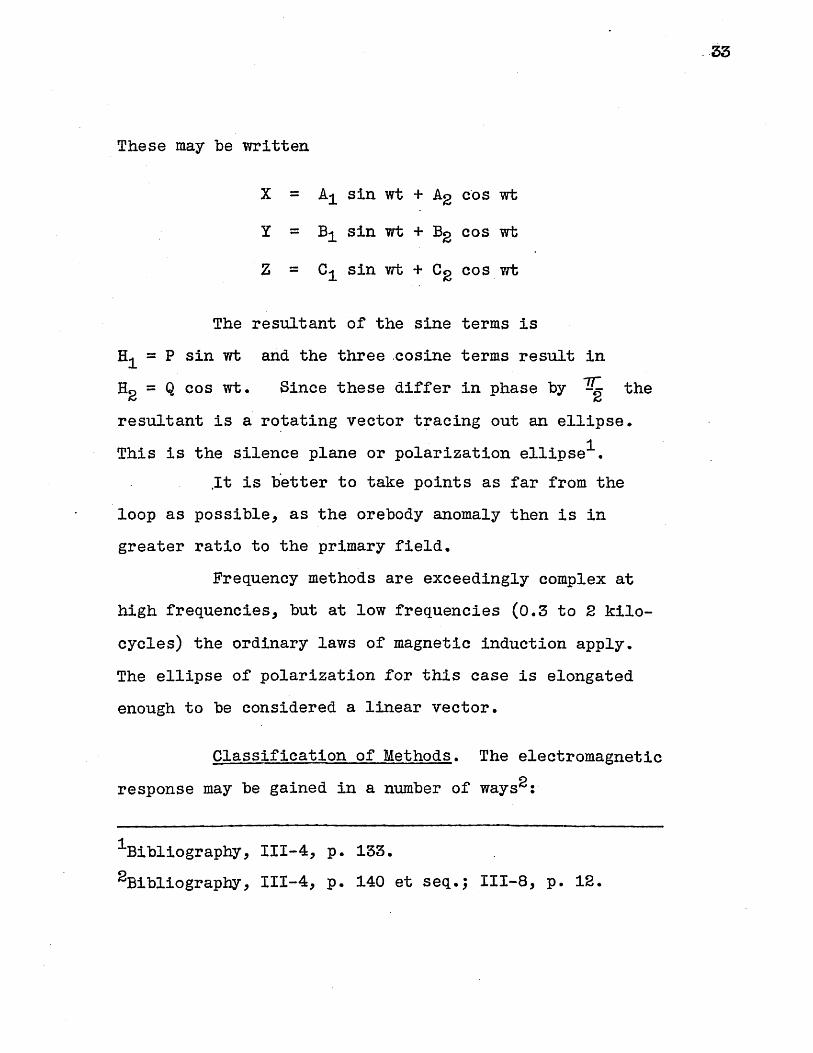
These may be written
X = A, sin wt + A2 cos wt
Y = B, sin wt + B2 cos wt
Z = C1 sin wt + C2 cos wt
The resultant of the sine terms is
H = P sin wt and the three cosine terms result in
H= Q cos wt. Since these differ in phase by - the
resultant is a rotating vector tracing out an ellipse.
1This is the silence plane or polarization ellipse
It is better to take points as far from the
loop as possible, as the orebody anomaly then is in
greater ratio to the primary field.
Frequency methods are exceedingly complex at
high frequencies, but at low frequencies (0.3 to 2 kilo-
cycles) the ordinary laws of magnetic induction apply.
The ellipse of polarization for this case is elongated
enough to be considered a linear vector.
Classification of Methods. The electromagnetic
response may be gained in a number of ways2:
1Bibliography, 111-4, p. 133.
2Bibliography, III-4, p. 140 et seq.; 111-8, p. 12.
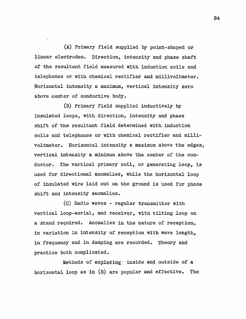
34
(A) Primary field supplied by point-shaped or
linear electrodes. Direction, intensity and phase shaft
of the resultant field measured with induction coils and
telephones or with chemical rectifier and millivoltmeter.
Horizontal intensity a maximum, vertical intensity zero
above center of conductive body.
(B) Primary field supplied inductively by
insulated loops, with direction, intensity and phase
shift of the resultant field determined with induction
coils and telephones or with chemical rectifier and milli-
voltmeter. Horizontal intensity a maximum above the edges,
vertical intensity a minimum above the center of the con-
ductor. The vertical primary coil, or generating loop, is
used for directional anomalies, while the horizontal loop
of insulated wire laid out on the ground is used for phase
shift and intensity anomalies.
(C) Radio waves - regular transmitter with
vertical loop-aerial, and receiver, with tilting loop on
a stand required. Anomalies in the nature of reception,
in variation in intensity of reception with wave length,
in frequency and in damping are recorded. Theory and
practice both complicated.
Methods of explortiig- inside and outside of a
horizontal loop as in (B) are popular and effective. The

35
primary field is approximately vertical 85 feet from the
loopi, and can be represented by the expression
H = HO sin wt
and the field of the orebody, being out of phase, can be
represented by
H = HO sin (wt + <).
A current in the search coil is thus generated
out of phase with the primary current by the angle
Detection. Three methods of detection are
possible: (1) compare the strength of the vertical field
at one point directly with the' strength at another point;
(2) locate magnetic equipotentials of the electromagnetic
field by means of search coils, and plot; (3) find silence
plane of the polarization ellipse and determine its axas
by noting the current in the coil when it measures the
horizontal component in the silence plane. The phase re-
lations between the conjugate diameters of the polarization
ellipse may also be deduced.
Two-Frame Method. The comparison method, used
in Europe and America by Sundberg, has had some success.
1Bibliography, III-i, p. 60.
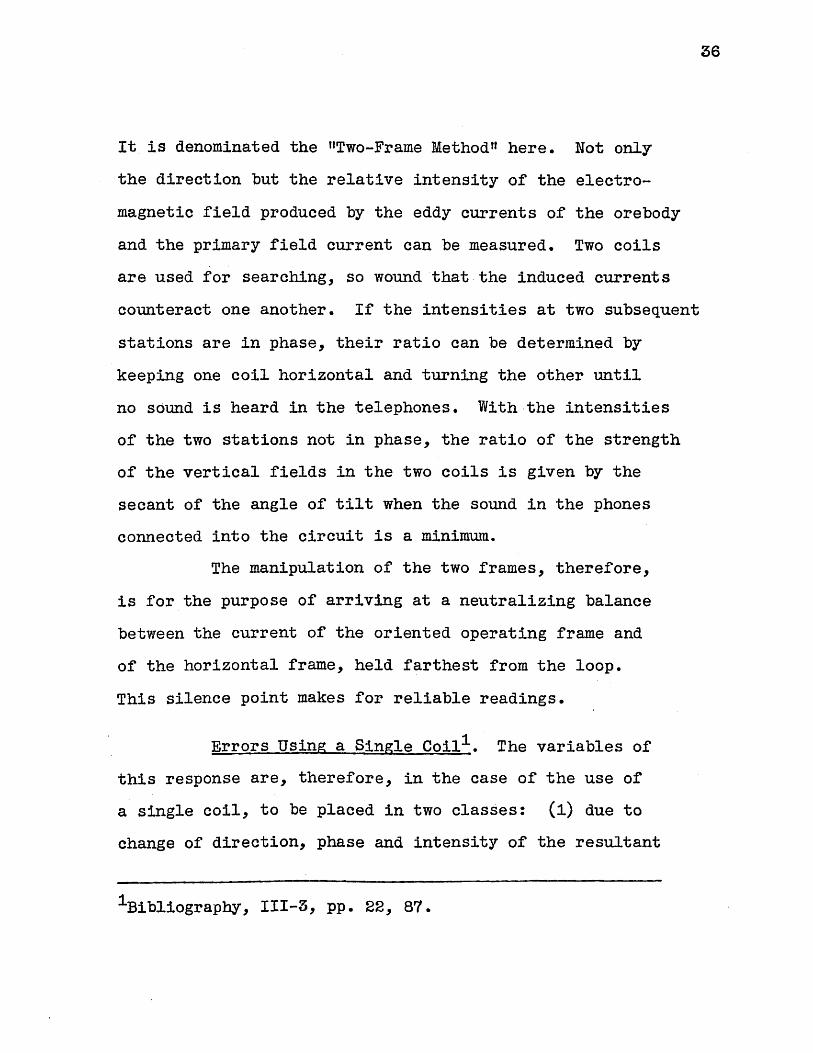
36
It is denominated the "Two-Frame Method' here. Not only
the direction but the relative intensity of the electro-
magnetic field produced by the eddy currents of the orebody
and the primary field current can be measured. Two coils
are used for searching, so wound that the induced currents
counteract one another. If the intensities at two subsequent
stations are in phase, their ratio can be determined by
keeping one coil horizontal and turning the other until
no sound is heard in the telephones. With the intensities
of the two stations not in phase, the ratio of the strength
of the vertical fields in the two coils is given by the
secant of the angle of tilt when the sound in the phones
connected into the circuit is a minimum.
The manipulation of the two frames, therefore,
is for the purpose of arriving at a neutralizing balance
between the current of the oriented operating frame and
of the horizontal frame, held farthest from the loop.
This silence point makes for reliable readings.
Errors Using a Single Coil1 . The variables of
this response are, therefore, in the case of the use of
a single coil, to be placed in two classes: (1) due to
change of direction, phase and intensity of the resultant
1Bibliography, 111-3, pp. 22, 87.
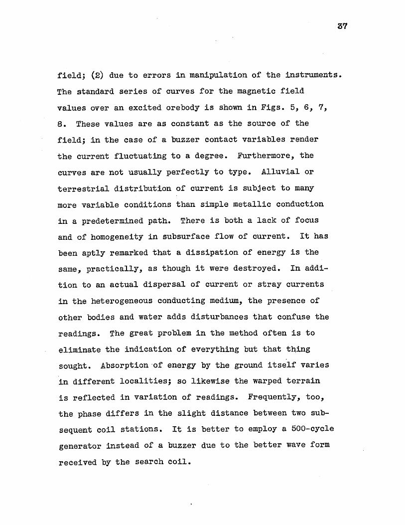
field; (2) due to errors in manipulation of the instruments.
The standard series of curves for the magnetic field
values over an excited orebody is shown in Figs. 5, 6, 7,
8. These values are as constant as the source of the
field; in the case of a buzzer contact variables render
the current fluctuating to a degree. Furthermore, the
curves are not usually perfectly to type. Alluvial or
terrestrial distribution of current is subject to many
more variable conditions than simple metallic conduction
in a predetermined path. There is both a lack of focus
and of homogeneity in subsurface flow of current. It has
been aptly remarked that a dissipation of energy is the
same, practically, as though it were destroyed. In addi-
tion to an actual dispersal of current or stray currents
in the heterogeneous conducting medium, the presence of
other bodies and water adds disturbances that confuse the
readings. The great problem in the method often is to
eliminate the indication of everything but that thing
sought. Absorption-of energy by the ground itself varies
in different localities; so likewise the warped terrain
is reflected in variation of readings. Frequently, too,
the phase differs in the slight distance between two sub-
sequent coil stations. It is better to employ a 500-cycle
generator instead of a buzzer due to the better wave form
received by the search coil.

IOrva r-y F1 cQ
orabody ftc/l
*TEli. 11 2'jK. 10
AnF1e
Fro n-pt Ee v. s/ie E/e v
1 .
P/cmn Elevotlon
P/41,07 V/e w
or)

39
Errors in Two-Frame Method. Such errors are
eliminated to a good extent in the Two-Frame Method by
taking the ratio of the field at two points over the
orebody.
Procedure in Taking Two-Frame Readings
Readings Along Lines. At a point 85 feet from
the loop is placed an operating frame free to move about
horizontal and vertical axes; and at 15 feet the horizontal
frame is held by an assistant. The proper angular (see
below) readings are recorded. From certain of these the
ratios V1/V2 and Hj/H2 can be calculated. Vi/V2 is
the ratio of the vertical component of the electromagnetic
field at points 1 and 2, and Hj/H2 the corresponding
horizontal field ratio. The horizontal frame is then moved
15 feet to point 3, and the readings repeated. Thenceforth,
the horizontal frame is kept 30 feet ahead of the operating
frame. The operating frame readings are taken at success-
ive 15-foot stations of the survey line. For layout of
the loop and stations, see Fig. 4. A tabular recording of
angles is made. Vj, H1 , V1 /V2 , HI/H2, V2 1 H2, V2 /V3,
H2/H3, and so on, are easily calculated. The ratio
V1/V2 is changed to V1 /V2 reduced by division by the
40
normal vertical component of the field of the loop. HE/H2
is considered as already reduced. In this way other
values at every point of the plan of survey (Fig. 4) can
be calculated. The values of V/V2 and H1/H2 are
plottedin the obtaining of the curve, at the point 1.
Thus complete curves .of the vertical field
ratios and of the horizontal field ratios are plotted
along a given line from the loop. Likewise, the curves
of V and H are plotted from each operating-coil sta-
tion value.
Phase Shift. Even with a single orebody the
difference in phase between the field from the ore and
that from the loop may be of use in indicating the ore-dir ectio n
body. Some advocate this method entirely.
Further Information
The reader is referred to F. L. Foster's Report ,
to gain further explanation of certain facts of the actual
survey. The following points can be easily found, and
therefore are not repeated:
A closed loop is preferable.
Reasons for working outside of the loop.
1Bibliography, III-1.
41
Calculation of results -
Derivation of V--/V K 7~~Z~~
Theory of curves obtained. Their derivation.
Determining width of conductors.
Determining dip of conductors.
The "qualitativer" test.
Scale of Plotted Results
All the values obtained are plotted on a scale
of 1 inch = 60 feet for distance, and 1 inch = 0.01 unit
for electrical data.
Procedure
Frame Constant. The method of obtaining the
frame constant is treated by Foster1 . This must be done
at the first of the survey.
Layout of Survey Plan. (Fig. 4).
Frame Technique. The survey is then begun.
The horizontal frame is held horizontal by means of the
level bubble at a point farther from the loop. The
Bibliography, III-1.
42
amplifier is switched on and angles of minimum sound
located by two observers with telephones. The method of
adjusting the operating frame to get these angles is im-
portant.
verticalAngle _. The/operating frame is first sighted
along the line through its radial-scale sights. It is
then turned off the line to a minimum response angle.
This is the angle epsilon.
Angle
is connected in
position of nul
such position i
the second angl
gives oC , th
s dsit and dk 2t The horizontal frame
. By moving about the horizontal axis a
1 or minimum sound is located. Another
s found to the opposite side of the vertical,
e approximating the first. Their average
e required value at point 1.
Angle 8 . The horizontal frame is disconnected.
Now a turning of the operating frame through an angle of
ninety degrees (at right angles to E position in a hori-
zontal plane) and adjustment about the horizontal axis
gives the angle .
Vector Explanation of Angles. The angle E
represents the angle at which the electromagnetic vector
is completely within the plane of the vertical loop, hence
when sound is least, if any. See Fig. 10.
43
The angles OC11 and OC 2 or , their
average, are the angles at which the horizontal frame
balances out the component of the resultant perpendicular
to the operating frame. The parallel component, since the
frame is oriented wi~th :it causes no current.
See Fig. 11.
In the case of the angle , the vector is
again completely within the plane of the operating frame.
See Fig. 11.
Interpretation of Curves
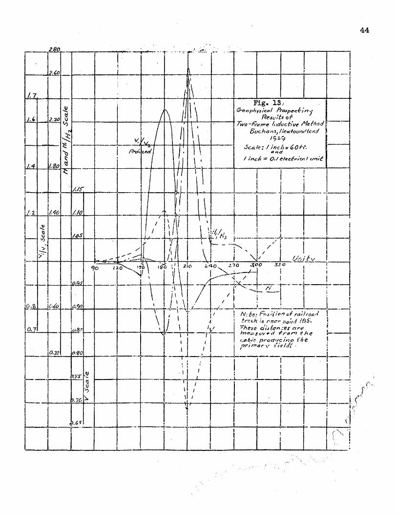
Curves Obtained. The curve given (Fig. 13)
represents the principal points of the curves obtained.
The following facts are discussed elsewhere
Vl/V2 reduced curve
maximum point - boundary of orebody nearest loop.
minimum point - approximately the other boundary.
H1 / H2 curve
Points where curve crosses the unity line indicate
boundaries.
V1 curve
Points of inflection indicate boundaries.
1Bibliography, III-1.
44
2.80, _
~~1 i
/.7~.-
Fig. 13Geophy5 cal Prospeckin
. 2.20 %J Results o f-~o ~~Two -rcrne /adoci&ve Ale ld ~~~/ 5Suc ha ns, New fouS/r nd
92.9)-Yc --..-a /e : / ;Nic h> 160 N.14
I ~ ~ /?iI / 'ines = 0/ efecdvien f unit6
A 80
90 1- 10 0 21o -070 3Of 0
j-r \o of /'"'. ____
is rn.r !l,
----------- OP~ th e
9Ie2 no i. p-od'ct- io
,-10,2 / ra f
.75 C
~*4 1
*1~~ JI''
'II--I--------- ~-.--------44-,------.----
I-- 1
I iC'
'4-
-I 777V7 ~
:
I
L
1
45
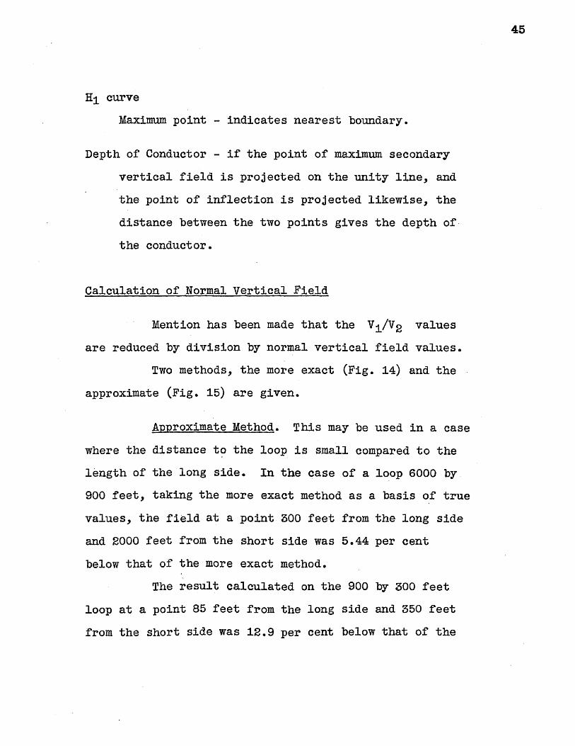
H1 curve
Maximum point - indicates nearest boundary.
Depth of Conductor - if the point of maximum secondary
vertical field is projected on the unity line, and
the point of inflection is projected likewise, the
distance between the two points gives the depth of
the conductor.
Calculation of Normal Vertical Field
Mention has been made that the V1 /V2 values
are reduced by division by normal vertical field values.
Two methods, the more exact (Fig. 14) and the
approximate (Fig. 15) are given.
Approximate Method. This may be used in a case
where the distance to the loop is small compared to the
length of the long side. In the case of a loop 6000 by
900 feet, taking the more exact method as a basis of true
values, the field at a point 300 feet from the long side
and 2000 feet from the short side was 5.44 per cent
below that of the more exact method.
The result calculated on the 900 by 300 feet
loop at a point 85 feet from the long side and 350 feet
from the short side was 12.9 per cent below that of the

9 aII-,CaIclotion of Normal
T
Fe I d Outside Loop--- Cai~7
soCAF-
Pofrt I B s n -sn(3 +a
~sini- rs,b
$iflfl-.51fl6C sin r -,sin A
a +.x
/S *tanl 3P 550
85r* t J50~
8 = -(90-o() =
1 5509 =390-3)
= to' 14.353
= to 6.410
= to' .909
tarf 1.100
0,
= 1-.0= 41.'10'
41-10 - 90-''.06=Ji1 6
tan-I
sin O=
sin p =
sin
sin .
sinA=i-449 = 55,01*
lan' .699 - 35.00*
35.00-90-8.1= 6. A *
-974'1
.9 88z
. 61A0
.1396
.5610
.8194
Sirl i . .513 6
s in - = .441i7;z594 c ts
ble= 350 ft = 10680 cwSc,= 550 fi
4+ix"*35S f+.= 6180 cers
It 130 cmS
4 7396-.56'1010680
.5136 -. 4111610 6
.61o +.8194
- . 8
lif 63-84G 6i
+ .611
S610 9j0 s *I /aamtere
46
900'300'
-.- 1808I I ~
'a

Fil. 15Co/culation5 of Normal Field out-tide Loop900 '
Approx mate
a b
Method
Suss/apere.30.5"
Where:-8= Normal FieId intensity o
C = H ov-17-Ontal distanceb = Vet,. a It
f point 7taken
itl fee-tI I I
30.5' [ 350+5
350+ 85
30.51. 20 9 + 1.90
550+ 65,550 %85
- 0.386
350 +3 85350 x 385
45502+ 385550 x 385
0.3i7 16-2
cl auss / c, m pe re-
x300'
I
=55. 6 x to0
48
more exact method. The error, therefore, of many stations
would be quite appreciable.
The approximate method, therefore, is only
good one for this small loop calculation from a ratio standpoint.
The reader is referred to Hudsonts Manual1 and
2and Edge and Laby for the formulae used in derivation of
the general field expressions. The latter also gives the
approximate expression used by the-author.
Description of Apparatus
The complete detail of apparatus is given in
the report of F. L. Foster3 .
Summary of Work Done
By geological reconnaissance and other methods
the general strike of sulphides was determined, and some
idea of their distribution gained for Two-Frame Survey.
The open-cut area was laid off preparatory to a few days
of actual Two-Frame Survey. The frequent rehearsals in-
culcated the technique of the Two-Frame Method in the
author's mind.
1Bibliography, III-10, p. 188, eqs. 781, 782.
2Bibliography, 111-5, p. 279.
3Bibliography, III-1.
49
Conclusions
The strike of the shear to the north is the
strike of the sulphides about the open-cut.
There is good reason to believe that much more
pyrrhotite occurs.
The nickel content of the sulphides is probably
too low to ever warrant large-scale production.
The actual Two-Frame Survey will delineate the
extent of the sulphides in a short time.
Other conclusions are to be found in the body
of the thesis.

50
III. SUGGESTIONS FOR FURTHER WORK
Mapping of Schlieren
The structure of the sulphide body could well
be determined in this way.
Survey of Related Areas
The low-lying drainage area to the northeast,
below the open-cut, might easily be prospected by many
methods, especially the equipotential. The author be-
lieves that for a prospecting class this would be a good
location. Burns Hill would be another likely area. He
suggests that any independent prospector consider trans-
portation difficulties, as well as the momentary fascina-
tion of such work for students who soon are enveloped in
other work. The best plan would be to camp on Nickel
Mine Hill.
The location of other bodies of sulphides in
other norite stocks might be possible. These occur some
miles away.
Pneumotectic Deposit
Much information is to be gained on such a
type of deposit here.
51
Cobalt and Platinum
Cobalt (see "Previous Work") -and traces of
platinum are probably present, and the area should
interest the mineralogist.
Dip-Needle and Magnetometer
This area is ideal for application of either
instrument. The question of whether or not the main
orebodies are in pyroxenite dikes (see p. 22) could be
thus investigated.

52
IV. BIBLIOGRAPHY
I. Geology
1. Dracut Nickel Ore, Geology and Concentration. Burton
and Spalding, Thesis in Central Library, Massachusetts
Institute of Technology, 1905.
2. Field Note-Book. Burton and Spalding, Files of
Geological Department, Massachusetts Institute of
Technology, 1905.
3. A Geological Reconnaissance of the Dracut Norite
Stock of Massachusetts. Ernest E. Fairbanks, Proceed-
ings, Boston Society of Natural History, Volume 58,
1925-28, 397-412. The reader is referred to
"Literature Cited", page 412, for a good list of
references on the history and geology of the deposit.
4. Mineral Deposits. Lindgren, Waldemar. McGraw-Hill
Book Co., New York, 1933.
5. Nickel Ores from Key West Mine, Nevada. Lindgren,
Waldemar. Economic Geology, Vol. 19, 1924, pages
309-319.
53
II. Mining
1. Thesis of Burton and Spalding above cited.
III. Electromagnetic Method
1. Report on Trip to Newfoundland for Study of Electrical
Prospecting Methods, June - July, 1928. Foster, F. L.
Typewritten report for use of mining students, Massa-
chusetts Institute of Technology.
2. Outline of Lectures, Foster, F. L., mimeographed sheets
for use of mining students in Geophysical Prospecting
3.13, Massachusetts Institute of Technology.
3. Geophysical Prospecting, 1929, volume of collected
articles published by American Institute of Mining
and Metallurgical Engineers, New York.
4. Applied Geophysics, Eve and Keys, Cambridge University
Press, Cambridge, 1933.
5. Principles and Practice of Geophysical Prospecting,
Edge and Laby, Cambridge University Press, Cambridge,
1931.
6. The Engineer's Manual, Hudson, R. G., John Wiley and
Sons, New York.
54
7. Traite Pratique de Prospection Geophysique,
Alexanian, C. L., Libraire Polytechnique Ch. Beranger,
Paris et Liege, 1932.
8. Geophysical Methods of Prospecting, Heiland, C. A.,
Colorado School of Mines Quarterly, Golden, Colorado,
March, 1929.
The reader is referred to "A Selected List of Books and
References on Geophysical Prospecting", Heiland, C. A.,
and Wantland, Dart, Colorado School of Mines Quarterly,
Golden, Colorado, July, 1931, for further information.
55
APPENDIX A
MAPS I - IV
*1

MASSACHUSETTS - NEW HAMPSHIRE
LOWELL SHEET
Map I
Mime

OpprOx.
of ot 0rofe outc 'op
Quartz-diorite-schist
Merrimackquartzite
Glaucophane-oligoclase
schist
Map of Dracut norite stock.Map II
Norite Quartz-micaschist
(Brimfield?)
A. A. S-1

D o'
k
'p
.,4
'
'I' 0
09,
41
'01
oI~
j
N
qZ
?.
C,
0 a a 0~
.~p
I
~ S
0~ aa
0
- w c
4",
0 *z
(A
z C
cm
0 -0
I
13
40..
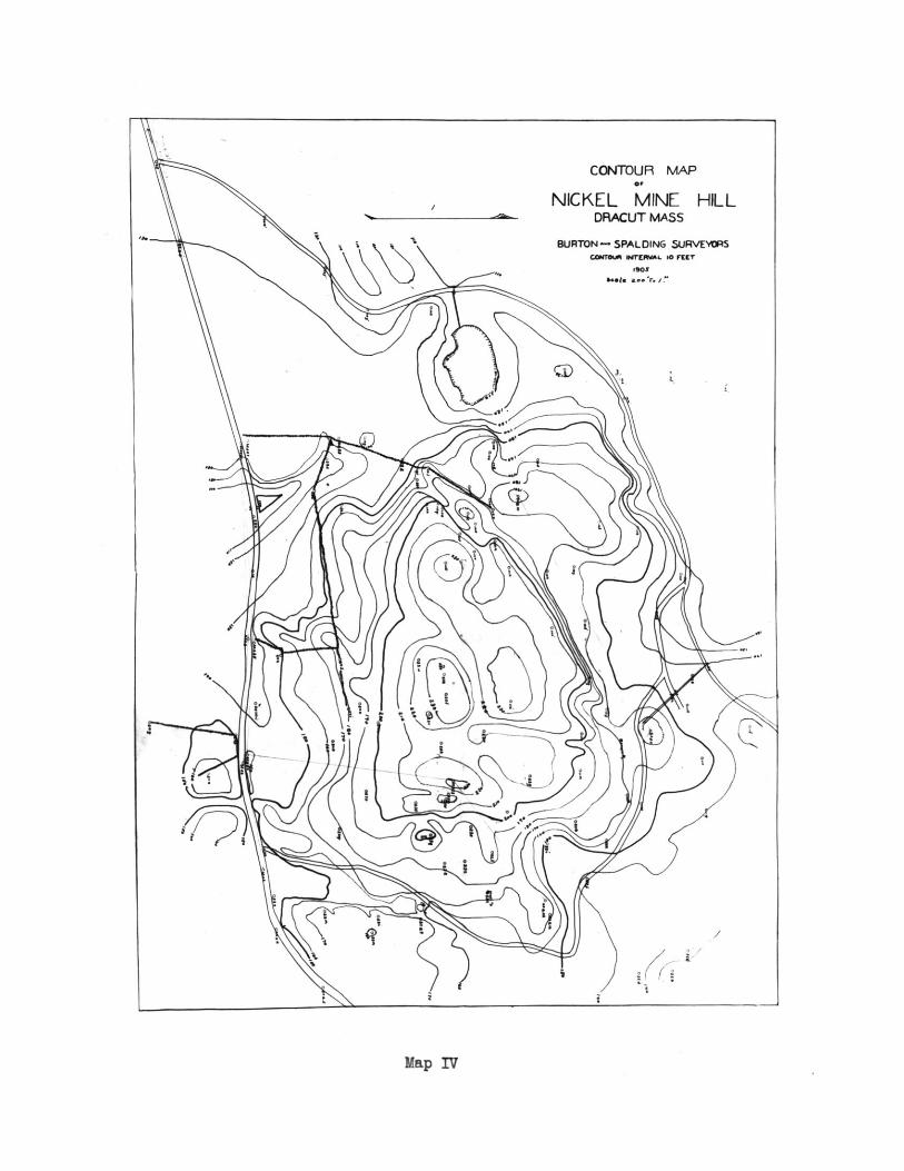
CONTOUR MAP0,
NICKEL MINE HILLDRACUT MASS
BURTON - SPALDING SURVEYORSCo&uruA erEWL 0 PmT
ba.. . ...
i
Map IV
i
Related Documents