POW’R LITE PL6000K Portable Light Tower Installation & Operating Manual 12/09 MN2488

PL6K
Dec 14, 2015
manual baldor PL6K
Welcome message from author
This document is posted to help you gain knowledge. Please leave a comment to let me know what you think about it! Share it to your friends and learn new things together.
Transcript
POW’R LITE PL6000K
Portable Light Tower
Installation & Operating Manual
12/09 MN2488
WARNING:CALIFORNIA PROPOSITION 65 WARNING:
Engine exhaust from this product contains chemicals knownto the state of California to cause cancer, birth defects andother reproductive harm.
WARNING:CALIFORNIA PROPOSITION 65 WARNING:
Battery posts, terminals and related accessories are known tothe state of California to cause cancer, birth defects and otherreproductive harm.
Table of Contents
Table of Contents iMN2488
Section 1Product Safety Information 1-1. . . . . . . . . . . . . . . . . . . . . . . . . . . . . . . . . . . . . . . . . . . . . . . . . . . . . . . . . . . . . . . . . . . . . . . .
Safety Notice 1-1. . . . . . . . . . . . . . . . . . . . . . . . . . . . . . . . . . . . . . . . . . . . . . . . . . . . . . . . . . . . . . . . . . . . . . . . . . . . . . . . . . Responsibility 1-1. . . . . . . . . . . . . . . . . . . . . . . . . . . . . . . . . . . . . . . . . . . . . . . . . . . . . . . . . . . . . . . . . . . . . . . . . . . . . . . . . IMPORTANT SAFETY INSTRUCTIONS 1-2. . . . . . . . . . . . . . . . . . . . . . . . . . . . . . . . . . . . . . . . . . . . . . . . . . . . . . . . . . Caution Statements 1-6. . . . . . . . . . . . . . . . . . . . . . . . . . . . . . . . . . . . . . . . . . . . . . . . . . . . . . . . . . . . . . . . . . . . . . . . . . . .
Section 2General Information 2-1. . . . . . . . . . . . . . . . . . . . . . . . . . . . . . . . . . . . . . . . . . . . . . . . . . . . . . . . . . . . . . . . . . . . . . . . . . . . . . .
Limited Warranty 2-1. . . . . . . . . . . . . . . . . . . . . . . . . . . . . . . . . . . . . . . . . . . . . . . . . . . . . . . . . . . . . . . . . . . . . . . . . . . . . . . Section 3Receiving & Installation 3-1. . . . . . . . . . . . . . . . . . . . . . . . . . . . . . . . . . . . . . . . . . . . . . . . . . . . . . . . . . . . . . . . . . . . . . . . . . .
Receiving & Inspection 3-1. . . . . . . . . . . . . . . . . . . . . . . . . . . . . . . . . . . . . . . . . . . . . . . . . . . . . . . . . . . . . . . . . . . . . . . . . Lifting the Light Tower 3-1. . . . . . . . . . . . . . . . . . . . . . . . . . . . . . . . . . . . . . . . . . . . . . . . . . . . . . . . . . . . . . . . . . . . . . . . . . Installation 3-1. . . . . . . . . . . . . . . . . . . . . . . . . . . . . . . . . . . . . . . . . . . . . . . . . . . . . . . . . . . . . . . . . . . . . . . . . . . . . . . . . . . .
Trailer Checks 3-2. . . . . . . . . . . . . . . . . . . . . . . . . . . . . . . . . . . . . . . . . . . . . . . . . . . . . . . . . . . . . . . . . . . . . . . . . . . . . Engine/Generator Checks 3-2. . . . . . . . . . . . . . . . . . . . . . . . . . . . . . . . . . . . . . . . . . . . . . . . . . . . . . . . . . . . . . . . . . Trailer Stabilization Checks 3-2. . . . . . . . . . . . . . . . . . . . . . . . . . . . . . . . . . . . . . . . . . . . . . . . . . . . . . . . . . . . . . . . . Light Mast Checks 3-2. . . . . . . . . . . . . . . . . . . . . . . . . . . . . . . . . . . . . . . . . . . . . . . . . . . . . . . . . . . . . . . . . . . . . . . . . Light Fixtures Checks 3-2. . . . . . . . . . . . . . . . . . . . . . . . . . . . . . . . . . . . . . . . . . . . . . . . . . . . . . . . . . . . . . . . . . . . . . Electrical Systems Checks 3-2. . . . . . . . . . . . . . . . . . . . . . . . . . . . . . . . . . . . . . . . . . . . . . . . . . . . . . . . . . . . . . . . . . Electrical Connections 3-3. . . . . . . . . . . . . . . . . . . . . . . . . . . . . . . . . . . . . . . . . . . . . . . . . . . . . . . . . . . . . . . . . . . . . .
Battery Connections 3-4. . . . . . . . . . . . . . . . . . . . . . . . . . . . . . . . . . . . . . . . . . . . . . . . . . . . . . . . . . . . . . . . . . . . . . . . . . . . Section 4Operation 4-1. . . . . . . . . . . . . . . . . . . . . . . . . . . . . . . . . . . . . . . . . . . . . . . . . . . . . . . . . . . . . . . . . . . . . . . . . . . . . . . . . . . . . . . . .
Preoperational Checklist 4-1. . . . . . . . . . . . . . . . . . . . . . . . . . . . . . . . . . . . . . . . . . . . . . . . . . . . . . . . . . . . . . . . . . . . . . . . Towing Instructions 4-2. . . . . . . . . . . . . . . . . . . . . . . . . . . . . . . . . . . . . . . . . . . . . . . . . . . . . . . . . . . . . . . . . . . . . . . . . . . . . Trailer Setup 4-3. . . . . . . . . . . . . . . . . . . . . . . . . . . . . . . . . . . . . . . . . . . . . . . . . . . . . . . . . . . . . . . . . . . . . . . . . . . . . . . . . . Light Tower Setup 4-4. . . . . . . . . . . . . . . . . . . . . . . . . . . . . . . . . . . . . . . . . . . . . . . . . . . . . . . . . . . . . . . . . . . . . . . . . . . . . . Engine Controller 4-5. . . . . . . . . . . . . . . . . . . . . . . . . . . . . . . . . . . . . . . . . . . . . . . . . . . . . . . . . . . . . . . . . . . . . . . . . . . . . . POW’R LITE Operation 4-6. . . . . . . . . . . . . . . . . . . . . . . . . . . . . . . . . . . . . . . . . . . . . . . . . . . . . . . . . . . . . . . . . . . . . . . . . Light Tower Stow Procedure 4-8. . . . . . . . . . . . . . . . . . . . . . . . . . . . . . . . . . . . . . . . . . . . . . . . . . . . . . . . . . . . . . . . . . . . . Trailer Setup for Towing 4-8. . . . . . . . . . . . . . . . . . . . . . . . . . . . . . . . . . . . . . . . . . . . . . . . . . . . . . . . . . . . . . . . . . . . . . . . .
Section 5Troubleshooting and Maintenance 5-1. . . . . . . . . . . . . . . . . . . . . . . . . . . . . . . . . . . . . . . . . . . . . . . . . . . . . . . . . . . . . . . . .
Maintenance 5-1. . . . . . . . . . . . . . . . . . . . . . . . . . . . . . . . . . . . . . . . . . . . . . . . . . . . . . . . . . . . . . . . . . . . . . . . . . . . . . . . . . General Checks 5-1. . . . . . . . . . . . . . . . . . . . . . . . . . . . . . . . . . . . . . . . . . . . . . . . . . . . . . . . . . . . . . . . . . . . . . . . . . . Change Engine Oil 5-1. . . . . . . . . . . . . . . . . . . . . . . . . . . . . . . . . . . . . . . . . . . . . . . . . . . . . . . . . . . . . . . . . . . . . . . . . Check Air Cleaner 5-1. . . . . . . . . . . . . . . . . . . . . . . . . . . . . . . . . . . . . . . . . . . . . . . . . . . . . . . . . . . . . . . . . . . . . . . . .
Flood Light Bulb Replacement 5-1. . . . . . . . . . . . . . . . . . . . . . . . . . . . . . . . . . . . . . . . . . . . . . . . . . . . . . . . . . . . . . . . . . . Cleaning 5-2. . . . . . . . . . . . . . . . . . . . . . . . . . . . . . . . . . . . . . . . . . . . . . . . . . . . . . . . . . . . . . . . . . . . . . . . . . . . . . . . . . . . . . POW’R LITE Troubleshooting Guide 5-3. . . . . . . . . . . . . . . . . . . . . . . . . . . . . . . . . . . . . . . . . . . . . . . . . . . . . . . . . . . . .

ii Table of Contents MN2488
Section 1Product Safety Information
Product Safety Information 1-1MN2488
Safety Notice Be sure that you are completely familiar with the safe operation of this equipment. Thisequipment may be connected to other machines that have rotating parts or parts that arecontrolled by this equipment. Improper use can cause serious or fatal injury. Alwaysdisconnect all electrical loads before starting the light tower.Installation and repair procedures require specialized skills with electrical generating equipmentand liquid cooled engine systems. Any person that installs or repairs this light tower must havethese specialized skills to ensure that this generating unit is safe to operate. Seek expert advisefor repairs or any questions about the safe installation and operation of this system.The precaution statements are general guidelines for the safe use and operation of this lighttower. It is not practical to list all unsafe conditions. Therefore, if you use a procedure that is notrecommended in this manual you must determine if it is safe for the operator and all personnel inthe proximity to the light tower and connected loads. If there is any question of the safety of aprocedure please seek expert advise before starting or stopping the light tower.This equipment contains high voltages. Electrical shock can cause serious or fatal injury. Onlyqualified personnel should attempt the start−up procedure or troubleshoot this equipment.This equipment may be connected to other machines that have rotating parts or parts that aredriven by this equipment. Improper use can cause serious or fatal injury. Only qualifiedpersonnel should attempt the start−up procedure or troubleshoot this equipment.
− System documentation must be available to anyone that operates this equipment at alltimes.
− Keep non-qualified personnel at a safe distance from this equipment.− Only qualified personnel familiar with the safe installation, operation and maintenance
of this device should attempt start-up or operating procedures.− Always stop engine before making or removing any connections.− Always stop engine and allow it to cool before refueling.
Responsibility When your light tower is delivered, it becomes the responsibility of the owner/operator to preventunsafe conditions and operation of the equipment. Some responsibilities include (but are notlimited to) the following:
1. It is the responsibility of the owner/operator to ensure that this equipment is correctlyand safely installed.
2. It is the responsibility of the owner/operator to ensure that this equipment, wheninstalled fully complies with all federal, state and local codes.
3. It is the responsibility of the owner/operator to ensure that any person operating thisequipment has been properly trained.
4. It is the responsibility of the owner/operator to ensure that any person operating thisequipment has access to all manuals and information required for the safe use andoperation of this equipment.
5. It is the responsibility of the owner/operator to ensure that it is properly maintained andsafety inspected at regular scheduled intervals.
6. It is the responsibility of the owner/operator to ensure that any person who has notbeen trained on the safe use of this equipment does not have access to thisequipment.
Read This Manual ThoroughlyIf you do not understand any concept, any procedure, any safety warning statement, any safetycaution statement or any portion of this manual, seek expert advise. We are happy to make sureyou understand the information in this manual so that you can safely enjoy the full use of thislight tower.
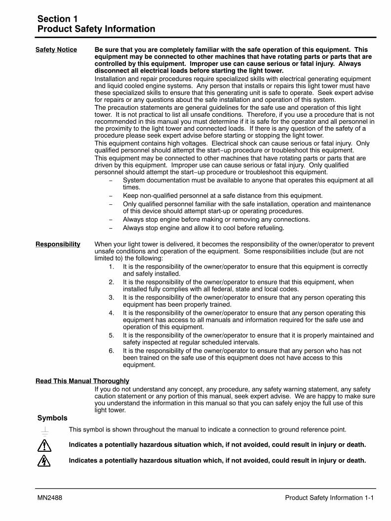
This symbol is shown throughout the manual to indicate a connection to ground reference point.
Symbols
Indicates a potentially hazardous situation which, if not avoided, could result in injury or death.
Indicates a potentially hazardous situation which, if not avoided, could result in injury or death.

1-2 Product Safety Information MN2488
Precaution Statements Used In This ManualThere are three classifications of precautionary statements used in this manual. The most criticalis a WARNING statement, then the Caution statement and the least critical is the Notestatement. The usage of each statement is as follows:
WARNING: Indicates a potentially hazardous situation which, if not avoided, could result in injury ordeath.
Caution: Indicates a potentially hazardous situation which, if not avoided, could result in damage toproperty.
Note: Additional information that is not critical to the installation or operation.
IMPORTANT SAFETY INSTRUCTIONSSAVE THESE INSTRUCTIONS − This manual contains important instructions for the light tower that shouldbe followed during installation, operation and maintenance.For ease of reading, the Warning statements are divided into four categories: Operation, Burn, Installation,and Maintenance.
Operation StatementsWARNING: If the trailer is not properly secured to the tow vehicles tow hitch, the trailer may separate
from the tow vehicle and cause severe injury or property damage. Always ensure that the towhitch and trailer tongue are properly connected, in good working condition and that safetychains are properly connected from the trailer to the tow vehicle.
WARNING: Never allow a person to ride in or on a trailer that is being towed. All states prohibitpassengers in towed vehicles. A person can fall off and be struck by another vehicle or runover by the towed trailer. Failure to observe this warning can result in death.
WARNING: Before using a tow vehicle, verify that the vehicle is designed for the load. Using a vehiclethat is too small is very dangerous. Be certain that it can handle the M.G.V.W. (MaximumGross Vehicle Weight) and the tongue weight for safe towing and braking.
WARNING: For a new trailer, the wheel lug nuts should be tightened to the proper torque specificationbefore use, after 50 miles of operation and every 100 miles of operation thereafter. Failure tocheck the lug nuts for proper tightness can result in an accident due to a wheel falling fromthe trailer.
WARNING: Never operate a trailer or tow vehicle that has a loose, missing or broken lug nut. The traileris designed for safe operation with all lug nuts installed and all at the proper torque rating.Operating the trailer with one or more broken or missing lug nuts greatly increases the loadon the remaining nuts and can cause failure of the remaining nuts that can result in anaccident due to a wheel falling from the trailer.
WARNING: Maximum safe highway speed for towing the light tower is 55 miles per hour. Excessivespeed or improper towing may result in an accident or damage.
WARNING: When erecting or stowing the mast assembly, be aware of the pinch points such as where thetower structures join or where the cable and winch are located. Careless operation can resultin injury. Keep extremities away from moving parts to avoid injury.
WARNING: Never stand under or close to an object that is being hoisted or lift into position. Accidentshappen and if the object falls or tips over you or someone else could be crushed by theweight of the object causing severe injury or death to to yourself or others. Always remain asafe distance from the object and always wear protective head gear (hard hat).
WARNING: Before erecting the mast assembly, be certain that the outriggers are properly set to stabilizethe light tower and that they are secure and are not damaged. Erecting the mast withoutsetting the outriggers can cause the light tower to tip over when raising the mast.
WARNING: Before erecting the mast assembly, be certain that there are no overhead wires. Contact withoverhead wiring presents an electrical shock hazard that may cause severe injury or death.
WARNING: Before erecting the mast assembly, be certain that there are no overhead obstructions thatthe mast will hit when raising it. Hitting an object (tree limb etc.) may damage the mast orcause the light tower to tip over and may result in injury or property damage.
WARNING: The mast assembly must remain in the stowed position until the outriggers are properly set tostabilize the trailer . Erecting the mast without setting the outriggers can cause the lighttower set to tip over when raising the mast.
WARNING: Never connect or disconnect loads during operation. Always connect load circuits beforestarting the engine and use external branch disconnects etc. to switch loads On/Off.
Continued on next page.

Product Safety Information 1-3MN2488
Operation Statements ContinuedWARNING: Never attempt to move the POW’R LITE when the mast is in the vertical position. All
Outrigger and trailer jacks must remain in position and the trailer level until the mast is in its’stowed position. Failure to follow this warning may result in severe injury and propertydamage if the trailer tips over.
WARNING: Never move or reposition a light tower when the mast is extended or in the vertical position.Unless the mast is in its stowed position, it may contact overhead wires or cause the lighttower to be unbalanced or tip over.
WARNING: Gasoline and diesel fuel are flammable and can cause fire, explosions, injury or death. Forstorage or refueling handle fuel with care and only in clean, approved, properly marked safetyfuel containers.
WARNING: Do not overfill the fuel tank. Only fill the tank to within 1/2� of the top of the tank to allowspace for fuel expansion. Overfilling of tank may cause fuel to spill out onto engine andcause fire or explosion.
WARNING: Clean up fuel spills by wiping completely dry before starting engine. Gasoline and diesel fuelare flammable and can cause fire, explosions, injury or death.
WARNING: Make sure the fuel cap is completely and securely closed after refueling to prevent spillage.Gasoline and diesel fuel are flammable and can cause fire, explosions, injury or death.
WARNING: Over crank indication can mean a loss of crank disconnect signal during the previous runperiod. Attempting to restart the engine with no crank disconnect signal can destroy thestarter motor, which can cause serious personal injury.
WARNING: High voltage is present whenever engine is running. Electrical shock can cause serious orfatal injury. Never operate electrical equipment while standing in water, on wet ground or withwet hands, feet or shoes or while barefoot.
WARNING: Never operate this light tower in a manner other than as described in this manual. Operationin any manner not described in this manual should be considered unsafe and should not beattempted. Never start the engine unless you have first verified that the installation andoperation of the light tower are as described in this manual.
WARNING: Be sure that you are completely familiar with the safe operation of this equipment. Thisequipment may be connected to other machines that have rotating parts or parts that arecontrolled by this equipment. Improper use can cause serious or fatal injury.
WARNING: Exhaust fumes/gases are extremely dangerous and can cause severe illness or death. Neverbreathe exhaust fumes produced by a running engine. Only run the engine outdoors whereventilation is plentiful. Exhaust gases contain carbon monoxide, a colorless, odorless andextremely dangerous gas that can cause unconsciousness or death. Symptoms of carbonmonoxide poisoning include: dizziness, nausea, headaches, sleepiness, vomiting orincoherence. If you or anyone else experiences these symptoms, get out into fresh airimmediately. Stop the engine and do not restart the engine until it has been inspected and ifnecessary repaired or reinstalled in a well ventilated area.
WARNING: Hot exhaust gasses must never be directed toward anything that may catch fire or explode.WARNING: This light tower must not be used on or near any forest covered, brush covered, or grass
covered land unless the engine’s exhaust system is equipped with a spark arrestor. Thespark arrestor must be maintained in effective working order by the operator.
WARNING: Never move a light tower that is running. Hazards are caused by moving a light tower that isrunning.
WARNING: Always wear safety glasses with side shields and hearing protection when working near thelight tower.
WARNING: Some parts of this light tower rotate during operation. Rotating parts can present extremedanger if clothing or body extremities are caught by the rotating part and can cause seriousor fatal injury. Never touch a part of the light tower until the engine has been stopped and allrotating parts are completely stopped. Also, disconnect the battery terminals to preventaccidental engine rotation during servicing.
WARNING: Be sure that you understand how to stop the engine quickly in case of an emergency situation.Become familiar with the controls and safety systems provided with this light tower.
WARNING: Improper operation may cause violent motion of connected equipment. Be certain thatunexpected movement will not cause injury to personnel or damage to equipment.
Continued on next page.
1-4 Product Safety Information MN2488
Operation Statements ContinuedWARNING: Never allow children or pets to be in the area where the light tower is running. The light tower
and the equipment being powered by the light tower may cause injury or death.WARNING: Never operate the light tower indoors or in a poorly ventilated area such as a tunnel or cave.
Exhaust fumes are extremely dangerous to all personnel that are in or in contact with thatarea.
WARNING: Never operate the light tower unless all guards, covers, shields and other safety items areproperly installed.
WARNING: Never permit anyone to operate the light tower without proper instructions. Be sure to keep acopy of this manual with the unit so that all users can be properly informed of its safeoperation.
WARNING: Do not put hands, feet, tools clothing or other objects near rotating parts such as drive shaft,pulley, belt etc. Rotating parts cause extremely dangerous situations because they can catchloose clothing or extremities and cause serious or fatal injury.
WARNING: When operating this light tower remain alert at all times. Never operate machinery whenphysically or mentally fatigued, or while under the influence of alcohol, drugs or medication.
WARNING: Never operate the engine when the air cleaner is removed. An engine backfire can causeserious burns.
WARNING: Never “jump start” a light tower to start the engine. If the battery charge is insufficient tostart the engine, charge or replace the battery and try to restart. Jump starting a battery cancause the battery to explode and cause severe injury or death to anyone in the area.
WARNING: High voltage is present whenever engine is running. Electrical shock can cause serious orfatal injury. Never operate electrical equipment while standing in water, on wet ground or withwet hands, feet or shoes or while barefoot.
WARNING: High voltage is present whenever the engine is running. Electrical shock can cause seriousor fatal injury.
WARNING: Do not smoke near light tower during operation or while refueling. Gasoline and diesel fuelare flammable and can cause fire, explosions, injury or death.
WARNING: Stop engine and allow engine to cool before refueling. Gasoline and diesel fuel are flammableand can cause fire, explosions, injury or death.
WARNING: Never store an engine with fuel in its tank indoors or in an enclosed, poorly ventilated areawhere gasoline fumes could reach an ignition source and cause an explosion. Fumes mayreach an open flame, electrical spark or pilot light as on a furnace, water heater, clothes dryer,etc. Gasoline and diesel fuel are flammable and can cause fire, explosions, injury or death.
WARNING: Operate the light tower only on a level surface. If the light tower is tilted during operation,fuel spillage may result. Gasoline and diesel fuel are flammable and can cause fire,explosions, injury or death.
WARNING: Keep light tower at least three feet away from buildings and other structures.WARNING: Keep light tower away from flammable or hazardous materials (trash, rags, lubricants,
explosives, paints etc.) and grass or leaf build up.WARNING: Keep a fire extinguisher near the light tower during use. An extinguisher rated “ABC” by the
National Fire Protection Association is appropriate.Burn StatementsWARNING: Light fixtures become extremely hot during use. To prevent severe burns, do not touch light
fixtures, bulbs or other components until they have cooled and no longer present a burn hazard.Wear protective clothing when placing the tower in the stowed position after use and do not allowany person to touch the light fixtures.
Continued on next page.WARNING: Do not touch the hot exhaust parts. In addition to a severe burn, the sudden involuntary jerk
of the hand or body part caused by contact with high voltage or a hot surface can result ininjury to yourself or others.
WARNING: Parts of this light tower are extremely hot during and after operation. To prevent severeburns, do not touch any part until you have first determined if the part is hot. Wear protectiveclothing and after use allow sufficient time for parts to cool before touching.
WARNING: Engine coolant is under pressure and is near the boiling point of water when engine is hot.Do not open the coolant system until the engine has completely cooled. Hot coolant cancause severe burns and other injuries. When engine is cool, coolant level can be checked.
Product Safety Information 1-5MN2488
Installation StatementsWARNING: Installation and servicing of batteries is to be performed or supervised by personnel
knowledgeable of batteries and the required precautions. Keep unauthorized personnel awayfrom batteries.
WARNING: Installation and repair procedures requires specialized skills with electrical generatingequipment and small engine systems. Any person that installs or performs repairs must havethese specialized skills to ensure that the light tower is safe to operate.
WARNING: Be sure all wiring complies with the National Electrical Code (NEC) and all regional and localcodes or CE Compliance. Improper wiring may cause a hazardous condition and exposure toelectrical hazards can cause serious injury or death.
WARNING: Be sure the system is properly grounded before applying power. Do not apply AC powerbefore you ensure that grounds are connected. Electrical shock can cause serious or fatalinjury. NEC requires that the frame and exposed conductive surfaces (metal parts) beconnected to an approved earth ground. Local codes may also require proper grounding oflight tower systems.
WARNING: Do not connect the generator output neutral to the frame or local ground. The generatoroutput is isolated from ground. NEC and local codes require that the generator output remainisolated from local ground reference.
WARNING: Place protective covers over all rotating parts such as drive shaft, pulley, belt etc. Rotatingparts cause extremely dangerous situations because they can catch loose clothing orextremities and cause serious or fatal injury.
WARNING: Unauthorized modification of a light tower may make the unit unsafe for operation or mayimpair the operation of the unit. Never start a light tower that has been modified or tamperedwith. Be sure that all covers and guards are properly installed and that the unit is safe beforestarting the engine. If you are unsure, seek expert advise before starting the engine.
WARNING: When transporting a light tower, secure the unit to prevent movement during transport.WARNING: Never connect this light tower to any buildings electrical system unless a licensed electrician
has installed an approved transfer switch. The National Electrical Code (NEC) requires thatconnection of a generator to any electrical circuit normally powered by means of an electricutility must be connected by means of approved transfer switch equipment so as to isolatethe electrical circuit from the utility distribution system during operation. Failure to isolatethe electrical circuits by such means may result in injury or death to utility power workers dueto backfeed of electrical energy onto the utility lines.
WARNING: Circuit overload protection must be provided in accordance with the National Electrical Codeand local regulations.
WARNING: Check Ground Fault Circuit Interrupt (GFCI) receptacles monthly by using the “Test” and“Reset” buttons.
WARNING: Have electrical circuits and wiring installed and checked by licensed electrician or qualifiedtechnician. Electrical shock can cause serious or fatal injury.
Maintenance StatementsWARNING: Installation and servicing of batteries is to be performed or supervised by personnel
knowledgeable of batteries and the required precautions. Keep unauthorized personnel awayfrom batteries.
WARNING: Disconnect the battery’s ground terminal before working in the vicinity of the battery orbattery wires. Contact with the battery can result in electrical shock when a tool accidentlytouches the positive battery terminal or wire. The risk of such shock is reduced when theground lead is removed during installation and maintenance.
WARNING: A battery presents a risk of fire and explosion because they generate hydrogen gas.Hydrogen gas is extremely explosive. Never jump start a battery, smoke in the area aroundthe battery or cause any spark to occur in the area around the battery.
WARNING: Do not mutilate the battery or dispose of a battery in a fire. The battery is capable ofexploding. If the battery explodes, electrolyte solution will be released in all directions.Battery electrolyte solution is caustic and can cause severe burns and blindness. Ifelectrolyte contacts skin or eyes, immediately flush the area with water and seek medicalattention quickly.
Continued on next page.
1-6 Product Safety Information MN2488
Maintenance Statements ContinuedWARNING: A battery presents a risk of electrical shock hazard and high short circuit current. Electrical
shock can cause serious or fatal injury. Never wear jewelry, watch or any metal objects whenin the area around the battery.
WARNING: The battery electrolyte is a dilute sulfuric acid that is harmful to the skin and eyes. It iselectrically conductive and corrosive. If electrolyte contacts the skin, flush the areaimmediately with water and wash it off using soap and water. If electrolyte contacts the eyes,immediately flush the eye thoroughly with water and seek medical attention quickly.
WARNING: Before cleaning, inspecting, repairing, refueling or performing any maintenance to the lighttower, always be sure the engine has stopped and that all rotating parts have also stopped.After stopping, certain components are still extremely hot so be careful not to get burned.
WARNING: Before servicing the light tower, be sure to disconnect the battery terminals to preventaccidental engine rotation or starting.
WARNING: Inspect all wiring frequently and replace any damaged, broken or frayed wiring or wires withdamaged insulation immediately. Electrical shock can cause serious or fatal injury.
WARNING: Disconnect all electrical wires and load devices from light tower power outlets beforeservicing the light tower. Electrical shock can cause serious or fatal injury. Always treatelectrical circuits as if they are energized.
WARNING: Check fuel tank, fuel line, and connections monthly for fuel leaks. Diesel is flammable andcan cause fire, explosions, injury or death. If a leak is found, replace only with approved pipeor components.
WARNING: Never store an engine with fuel in its tank indoors or in an enclosed, poorly ventilated areawhere gasoline fumes could reach an ignition source and cause an explosion.
WARNING: Before servicing the generator set, be sure to disconnect the glow plugs or spark plug wiresand the battery terminals to prevent accidental engine rotation or starting.
WARNING: Engine coolant is under pressure and is near the boiling point of water when engine is hot.Do not open the coolant system until the engine has completely cooled. Hot coolant cancause severe burns and other injuries. When engine is cool, coolant level can be checked.
Caution StatementsCaution: Never start the engine with any of the lights on, or with any electrical load connected, as
damage to the light tower may result.Caution: Never stop the engine with any of the lights on, or with any electrical load connected, as
damage to the light tower may result.Caution: Careless handling or storage of the light fixtures can damage the fixtures, lenses, and/or bulbs.Caution: Do not overfill the engine oil. Serious damage to the engine can result from overfilling the oil.Caution: Never use explosive engine starting fluids. Please read the engine manual and unit placards
carefully before starting the engine. Starting fluids are not compatible with the preheat cycle.Caution: Do not operate preheat for more than 30 seconds or the heating element may be damaged.Caution: Do not engage the starter motor for more than 60 seconds at a time or damage may result.Caution: Before towing, be sure that the jack and outriggers are properly and securely stowed for
travel to prevent trailer damage.Caution: Do not apply high voltage to windings (start the light tower) in a moisture−saturated
condition. Moisture can cause insulation breakdown, making it necessary to return the lighttower to the factory for repair, and consequent expense and loss of time.
Caution: Use only original equipment or authorized replacement parts. Using the correct parts willassure continued safe operation as designed.
Caution: Do not tamper with or change the engine speed. Engine speed is factory set to produce thecorrect voltage and output frequency.
Caution: Never operate the engine without a muffler and spark arrestor. The engine is designed tohave the correct exhaust components installed. Operating without these components canpresent a fire hazard, cause excessive exhaust gases and cause damage to engine.
Caution: Operate the light tower only on a level surface. Operation of the light tower on an incline orslope may degrade engine lubrication and result in engine failure.
Caution: Always fill fuel tank with clean fresh fuel before use. Never leave fuel in tank for long storageperiods. Old fuel becomes stale and can damage the fuel system causing the engine not tostart. Always drain the fuel tank after use before storage.
Section 2General Information
General Information 2-1MN2488
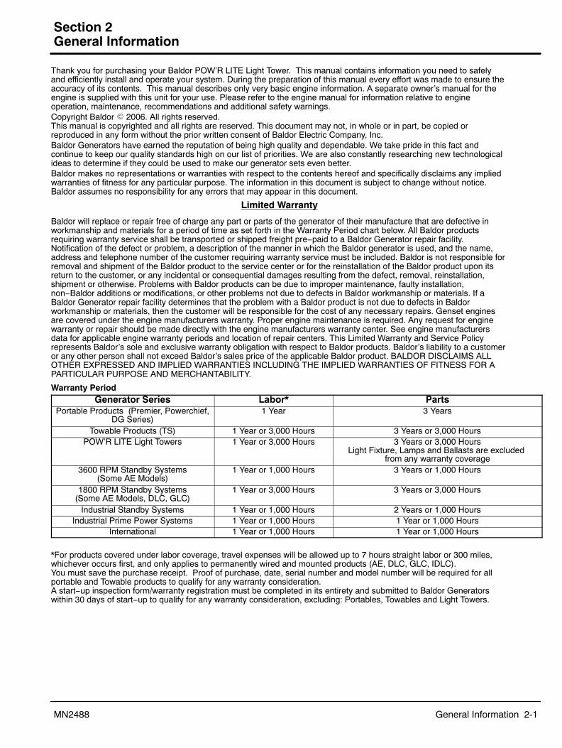
Thank you for purchasing your Baldor POW’R LITE Light Tower. This manual contains information you need to safelyand efficiently install and operate your system. During the preparation of this manual every effort was made to ensure theaccuracy of its contents. This manual describes only very basic engine information. A separate owner’s manual for theengine is supplied with this unit for your use. Please refer to the engine manual for information relative to engineoperation, maintenance, recommendations and additional safety warnings.Copyright Baldor � 2006. All rights reserved. This manual is copyrighted and all rights are reserved. This document may not, in whole or in part, be copied orreproduced in any form without the prior written consent of Baldor Electric Company, Inc.Baldor Generators have earned the reputation of being high quality and dependable. We take pride in this fact andcontinue to keep our quality standards high on our list of priorities. We are also constantly researching new technologicalideas to determine if they could be used to make our generator sets even better.Baldor makes no representations or warranties with respect to the contents hereof and specifically disclaims any impliedwarranties of fitness for any particular purpose. The information in this document is subject to change without notice.Baldor assumes no responsibility for any errors that may appear in this document.
Limited Warranty
Baldor will replace or repair free of charge any part or parts of the generator of their manufacture that are defective inworkmanship and materials for a period of time as set forth in the Warranty Period chart below. All Baldor productsrequiring warranty service shall be transported or shipped freight pre−paid to a Baldor Generator repair facility.Notification of the defect or problem, a description of the manner in which the Baldor generator is used, and the name,address and telephone number of the customer requiring warranty service must be included. Baldor is not responsible forremoval and shipment of the Baldor product to the service center or for the reinstallation of the Baldor product upon itsreturn to the customer, or any incidental or consequential damages resulting from the defect, removal, reinstallation,shipment or otherwise. Problems with Baldor products can be due to improper maintenance, faulty installation,non−Baldor additions or modifications, or other problems not due to defects in Baldor workmanship or materials. If aBaldor Generator repair facility determines that the problem with a Baldor product is not due to defects in Baldorworkmanship or materials, then the customer will be responsible for the cost of any necessary repairs. Genset enginesare covered under the engine manufacturers warranty. Proper engine maintenance is required. Any request for enginewarranty or repair should be made directly with the engine manufacturers warranty center. See engine manufacturersdata for applicable engine warranty periods and location of repair centers. This Limited Warranty and Service Policyrepresents Baldor’s sole and exclusive warranty obligation with respect to Baldor products. Baldor’s liability to a customeror any other person shall not exceed Baldor’s sales price of the applicable Baldor product. BALDOR DISCLAIMS ALLOTHER EXPRESSED AND IMPLIED WARRANTIES INCLUDING THE IMPLIED WARRANTIES OF FITNESS FOR APARTICULAR PURPOSE AND MERCHANTABILITY.
Warranty PeriodGenerator Series Labor* Parts
Portable Products (Premier, Powerchief,DG Series)
1 Year 3 Years
Towable Products (TS) 1 Year or 3,000 Hours 3 Years or 3,000 HoursPOW’R LITE Light Towers 1 Year or 3,000 Hours 3 Years or 3,000 Hours
Light Fixture, Lamps and Ballasts are excluded from any warranty coverage
3600 RPM Standby Systems(Some AE Models)
1 Year or 1,000 Hours 3 Years or 1,000 Hours
1800 RPM Standby Systems(Some AE Models, DLC, GLC)
1 Year or 3,000 Hours 3 Years or 3,000 Hours
Industrial Standby Systems 1 Year or 1,000 Hours 2 Years or 1,000 HoursIndustrial Prime Power Systems 1 Year or 1,000 Hours 1 Year or 1,000 Hours
International 1 Year or 1,000 Hours 1 Year or 1,000 Hours
*For products covered under labor coverage, travel expenses will be allowed up to 7 hours straight labor or 300 miles,whichever occurs first, and only applies to permanently wired and mounted products (AE, DLC, GLC, IDLC).You must save the purchase receipt. Proof of purchase, date, serial number and model number will be required for allportable and Towable products to qualify for any warranty consideration.A start−up inspection form/warranty registration must be completed in its entirety and submitted to Baldor Generatorswithin 30 days of start−up to qualify for any warranty consideration, excluding: Portables, Towables and Light Towers.

2-2 General Information MN2488

Section 3Receiving & Installation
Receiving & Installation 3-1MN2488
Receiving & Inspection When you receive your light tower, there are several things you should do immediately.1. Observe the condition of the light tower and report any damage immediately to the
carrier that delivered your system.2. Verify that the part number of the system you received is the same as the part number
listed on your purchase order.3. If the system is to be stored for several weeks before use, be sure that it is stored in a
location that conforms to published storage temperature and humidity specifications.Lifting the Light Tower When lift or hoist equipment is used to lift the light tower and move it to position, be
careful not to contact overhead wires or other obstacles. The unit can weigh as much as 2,000lbs. Be sure lift or hoist equipment has appropriate tires for the terrain to avoid becoming stuckor tipping over. The lift slots are designed for use with a fork lift. A spreader bar and chains (see Figure 3-1) can also be used.
Installation The light tower is delivered completely assembled, tested and ready for use. No assembly isrequired. However, before putting the light tower to use the system should be completelychecked to ensure it is ready for operation. See Figure 3-1.The light tower (unit) has six major systems that will be checked individually before use, theseare:
1. Trailer2. Engine/Generator3. Trailer Stabilization System4. Light Mast5. Light Fixtures6. Electrical Systems
Figure 3-1 POW’R LITE Component Identification
Jack
Coupler
Coupler Handle
SafetyChains
Light Mast
Trailer Outriggers
Light Fixtures
Trailer
Muffler
LiftSlots
TiltWinch
LiftWinch
Outriggers Extended
Tilt Lock
MastLock
Engine/Generator Compartment
If a fork lift is not available to lift the light tower,use spreader bars, chains eyehooks and otherhardware that is of sufficient strength to lift atleast three times the weight of the unit.
TowBar
LiftSlot
LiftSlot
3-2 Receiving & Installation MN2488
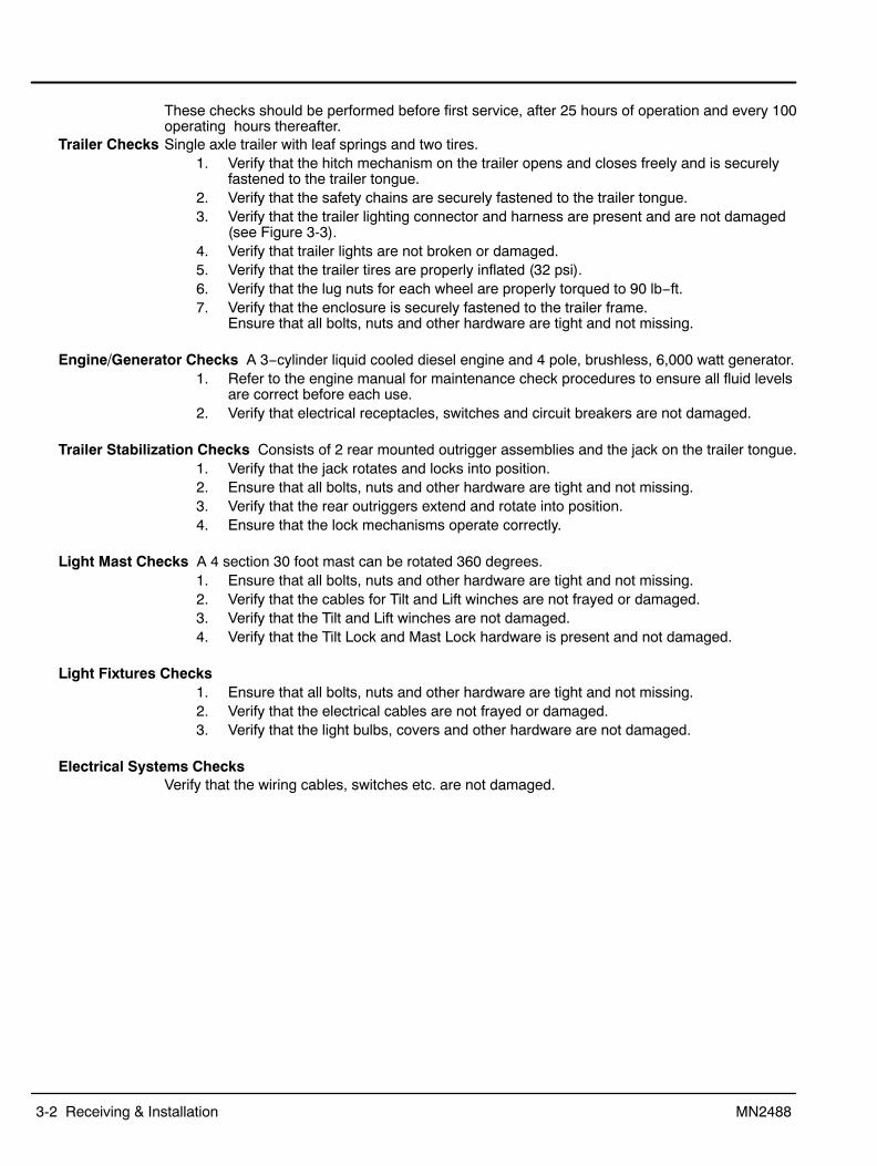
These checks should be performed before first service, after 25 hours of operation and every 100operating hours thereafter.
Trailer Checks Single axle trailer with leaf springs and two tires.1. Verify that the hitch mechanism on the trailer opens and closes freely and is securely
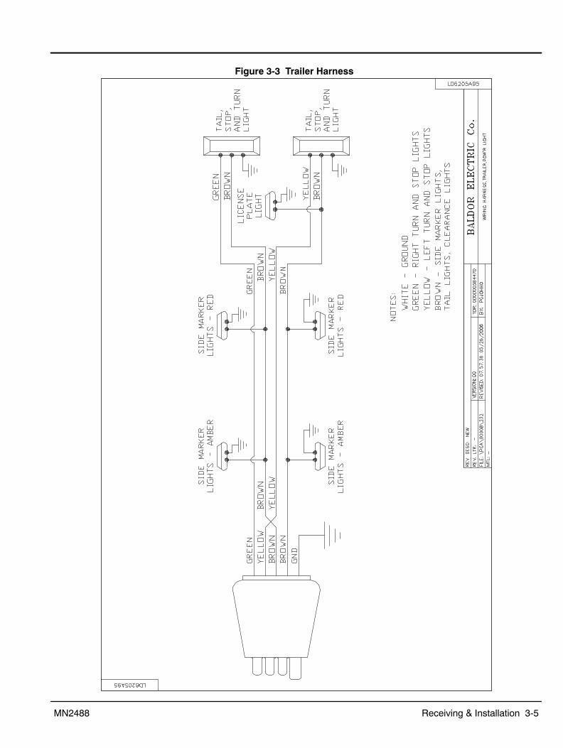
fastened to the trailer tongue.2. Verify that the safety chains are securely fastened to the trailer tongue.3. Verify that the trailer lighting connector and harness are present and are not damaged
(see Figure 3-3).4. Verify that trailer lights are not broken or damaged.5. Verify that the trailer tires are properly inflated (32 psi).6. Verify that the lug nuts for each wheel are properly torqued to 90 lb−ft.7. Verify that the enclosure is securely fastened to the trailer frame.
Ensure that all bolts, nuts and other hardware are tight and not missing.
Engine/Generator Checks A 3−cylinder liquid cooled diesel engine and 4 pole, brushless, 6,000 watt generator.1. Refer to the engine manual for maintenance check procedures to ensure all fluid levels
are correct before each use.2. Verify that electrical receptacles, switches and circuit breakers are not damaged.
Trailer Stabilization Checks Consists of 2 rear mounted outrigger assemblies and the jack on the trailer tongue.1. Verify that the jack rotates and locks into position.2. Ensure that all bolts, nuts and other hardware are tight and not missing.3. Verify that the rear outriggers extend and rotate into position.4. Ensure that the lock mechanisms operate correctly.
Light Mast Checks A 4 section 30 foot mast can be rotated 360 degrees.1. Ensure that all bolts, nuts and other hardware are tight and not missing.2. Verify that the cables for Tilt and Lift winches are not frayed or damaged.3. Verify that the Tilt and Lift winches are not damaged.4. Verify that the Tilt Lock and Mast Lock hardware is present and not damaged.
Light Fixtures Checks1. Ensure that all bolts, nuts and other hardware are tight and not missing.2. Verify that the electrical cables are not frayed or damaged.3. Verify that the light bulbs, covers and other hardware are not damaged.
Electrical Systems ChecksVerify that the wiring cables, switches etc. are not damaged.
Receiving & Installation 3-3MN2488
Electrical Connections Class 1 wiring methods must be used for field wiring connections to terminals of a class 2circuit. It is the responsibility of the owner/operator to arrange for these procedures to beperformed by a licensed electrical contractor and ensure conformance to all applicable codesincluding local codes peculiar to your municipality/city/county and state. Wire size and insulationtype should be as required by NEC (National Electrical Code) and local codes.
Warning: Never connect this light tower to the electrical system of any building unless a licensedelectrician has installed an approved transfer switch. The national electrical code (NEC)requires that connection of a generator to any electrical circuit normally powered by means ofan electric utility must be connected by means of approved transfer switch equipment toisolate the electrical circuit from the utility distribution system when the unit is operating.Failure to isolate the electrical circuits by such means may result in injury or death to utilitypower workers due to backfeed of electrical energy onto the utility lines.
Intended Use The intended purpose of this light tower is to provide portable lighting where main utility powersupply is not available. It is not intended to connect to a building’s wiring system.
Protection Single Phase circuit protection is provided within the light tower.
Electrical Outlets The electrical panel provides a duplex 120V, 20A GFCI receptacle and a 240V, 30A twist lockreceptacle. Both receptacles may be used at the same time as the Light Mast provided the totalelectrical load does not exceed the generators rated output. GFCI (Ground Fault CircuitInterrupter) provides ground fault protection.
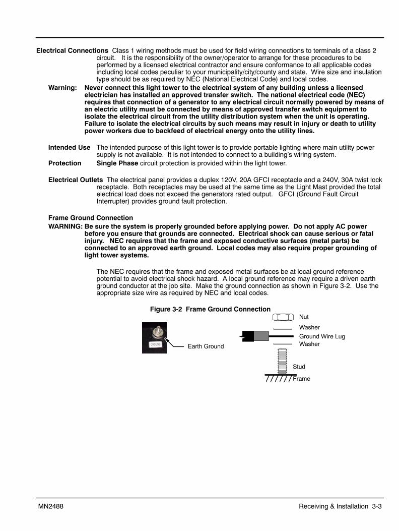
Frame Ground ConnectionWARNING: Be sure the system is properly grounded before applying power. Do not apply AC power
before you ensure that grounds are connected. Electrical shock can cause serious or fatalinjury. NEC requires that the frame and exposed conductive surfaces (metal parts) beconnected to an approved earth ground. Local codes may also require proper grounding oflight tower systems.
The NEC requires that the frame and exposed metal surfaces be at local ground referencepotential to avoid electrical shock hazard. A local ground reference may require a driven earthground conductor at the job site. Make the ground connection as shown in Figure 3-2. Use theappropriate size wire as required by NEC and local codes.
Figure 3-2 Frame Ground Connection
Earth Ground
Frame
Stud
WasherGround Wire Lug
Nut
Washer
3-4 Receiving & Installation MN2488
Battery ConnectionsWARNING: Removal, installation and servicing of batteries is to be performed or supervised by personnel
knowledgeable of batteries and the required precautions. Keep unauthorized personnel awayfrom batteries.
WARNING: Do not mutilate the battery or dispose of a battery in a fire. The battery is capable ofexploding. If the battery explodes, electrolyte solution will be released in all directions.Battery electrolyte solution is caustic and can cause severe burns and blindness. Ifelectrolyte contacts skin or eyes, immediately flush the area with water and seek medicalattention quickly.
WARNING: A battery presents a risk of electrical shock hazard and high short circuit current. Thefollowing precautions are to be followed when working on batteries:
1. Remove watches, rings, necklaces and all other metal objects.2. Use tools with insulated handles.3. Wear rubber gloves and boots.
WARNING: The battery electrolyte is a dilute sulfuric acid that is harmful to the skin and eyes. It iselectrically conductive and corrosive. The following precautions are to be followed whenworking on batteries:
1. Wear full eye protection (safety glasses or goggles) and protective clothing.2. Where electrolyte contacts the skin, flush the area immediately with water and wash it
off using soap and water.3. Where electrolyte contacts the eyes, immediately flush the eye thoroughly with water
and seek medical attention quickly.4. Spilled electrolyte is to be washed down with an acid neutralizing agent. A common
practice is to use a solution of one pound (500 grams) bicarbonate of soda to onegallon (four liters) of water. The bicarbonate solution is to be added until evidence ofreaction (foaming) has ceased. The resulting liquid is to be flushed with water and thearea dried.
WARNING: A battery presents a risk of fire because they generate hydrogen gas. Hydrogen gas isextremely explosive. Never jump start a battery, smoke in the area around the battery orcause any spark to occur in the area around the battery. The following precautions are to befollowed when working on batteries:
1. Do not smoke when near batteries.2. Do not cause flame or spark in battery area.3. Discharge static electricity from body before touching batteries by first touching a
grounded metal surface.WARNING: Disconnect the battery’s ground terminal before working in the vicinity of the battery or
battery wires. Contact with the battery can result in electrical shock when a tool accidentaltouches the positive battery terminal or wire. The risk of such shock is reduced when theground lead is removed during installation and maintenance.
Procedure: The correct type battery must be installed in the battery compartment provided. Installation andservicing of batteries is to be performed or supervised by personnel knowledgeable of batteriesand the required precautions. Keep unauthorized personnel away from batteries.
1. Open access doors and locate battery tray.2. Remove the old battery.3. Install the new battery.4. Connect the positive lead to the positive (+) battery terminal.5. Connect the negative lead to the negative (−) battery terminal.6. Do not lay tools or metal parts on top of batteries.
Receiving & Installation 3-5MN2488
Figure 3-3 Trailer Harness

3-6 Receiving & Installation MN2488
Section 4Operation
Operation 4-1MN2488
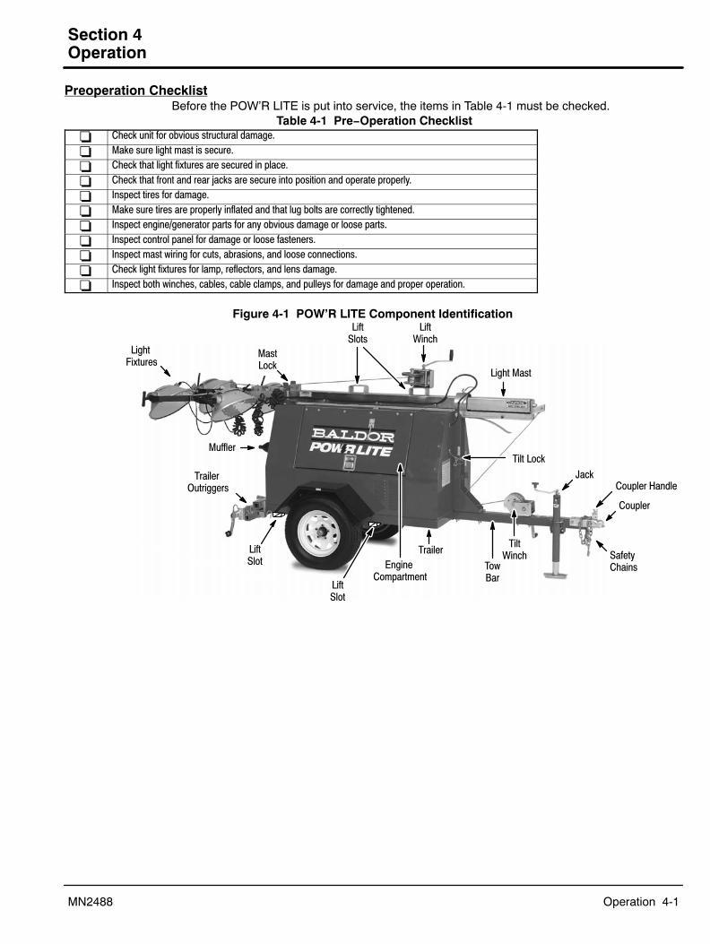
Preoperation ChecklistBefore the POW’R LITE is put into service, the items in Table 4-1 must be checked.
Table 4-1 Pre−Operation Checklist� Check unit for obvious structural damage.
� Make sure light mast is secure.
� Check that light fixtures are secured in place.
� Check that front and rear jacks are secure into position and operate properly.
� Inspect tires for damage.
� Make sure tires are properly inflated and that lug bolts are correctly tightened.
� Inspect engine/generator parts for any obvious damage or loose parts.
� Inspect control panel for damage or loose fasteners.
� Inspect mast wiring for cuts, abrasions, and loose connections.
� Check light fixtures for lamp, reflectors, and lens damage.
� Inspect both winches, cables, cable clamps, and pulleys for damage and proper operation.
Figure 4-1 POW’R LITE Component Identification
Jack
Coupler
Coupler Handle
SafetyChains
Light Mast
Trailer Outriggers
Light Fixtures
Trailer
Muffler
LiftSlots
TiltWinch
LiftWinch
Tilt Lock
MastLock
Engine Compartment
TowBar
LiftSlot
LiftSlot
4-2 Operation MN2488
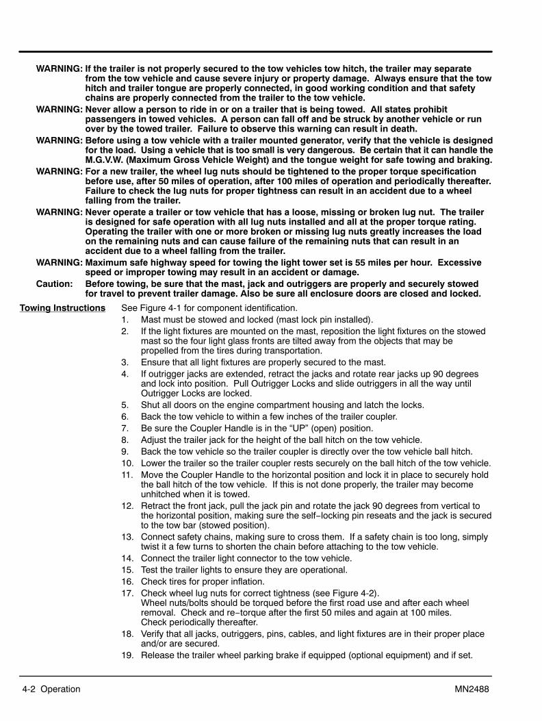
WARNING: If the trailer is not properly secured to the tow vehicles tow hitch, the trailer may separatefrom the tow vehicle and cause severe injury or property damage. Always ensure that the towhitch and trailer tongue are properly connected, in good working condition and that safetychains are properly connected from the trailer to the tow vehicle.
WARNING: Never allow a person to ride in or on a trailer that is being towed. All states prohibitpassengers in towed vehicles. A person can fall off and be struck by another vehicle or runover by the towed trailer. Failure to observe this warning can result in death.
WARNING: Before using a tow vehicle with a trailer mounted generator, verify that the vehicle is designedfor the load. Using a vehicle that is too small is very dangerous. Be certain that it can handle theM.G.V.W. (Maximum Gross Vehicle Weight) and the tongue weight for safe towing and braking.
WARNING: For a new trailer, the wheel lug nuts should be tightened to the proper torque specificationbefore use, after 50 miles of operation, after 100 miles of operation and periodically thereafter.Failure to check the lug nuts for proper tightness can result in an accident due to a wheelfalling from the trailer.
WARNING: Never operate a trailer or tow vehicle that has a loose, missing or broken lug nut. The traileris designed for safe operation with all lug nuts installed and all at the proper torque rating.Operating the trailer with one or more broken or missing lug nuts greatly increases the loadon the remaining nuts and can cause failure of the remaining nuts that can result in anaccident due to a wheel falling from the trailer.
WARNING: Maximum safe highway speed for towing the light tower set is 55 miles per hour. Excessivespeed or improper towing may result in an accident or damage.
Caution: Before towing, be sure that the mast, jack and outriggers are properly and securely stowedfor travel to prevent trailer damage. Also be sure all enclosure doors are closed and locked.
Towing Instructions See Figure 4-1 for component identification.1. Mast must be stowed and locked (mast lock pin installed).2. If the light fixtures are mounted on the mast, reposition the light fixtures on the stowed
mast so the four light glass fronts are tilted away from the objects that may bepropelled from the tires during transportation.
3. Ensure that all light fixtures are properly secured to the mast.4. If outrigger jacks are extended, retract the jacks and rotate rear jacks up 90 degrees
and lock into position. Pull Outrigger Locks and slide outriggers in all the way untilOutrigger Locks are locked.
5. Shut all doors on the engine compartment housing and latch the locks.6. Back the tow vehicle to within a few inches of the trailer coupler.7. Be sure the Coupler Handle is in the “UP” (open) position.8. Adjust the trailer jack for the height of the ball hitch on the tow vehicle.9. Back the tow vehicle so the trailer coupler is directly over the tow vehicle ball hitch.10. Lower the trailer so the trailer coupler rests securely on the ball hitch of the tow vehicle.11. Move the Coupler Handle to the horizontal position and lock it in place to securely hold
the ball hitch of the tow vehicle. If this is not done properly, the trailer may becomeunhitched when it is towed.
12. Retract the front jack, pull the jack pin and rotate the jack 90 degrees from vertical tothe horizontal position, making sure the self−locking pin reseats and the jack is securedto the tow bar (stowed position).
13. Connect safety chains, making sure to cross them. If a safety chain is too long, simplytwist it a few turns to shorten the chain before attaching to the tow vehicle.
14. Connect the trailer light connector to the tow vehicle.15. Test the trailer lights to ensure they are operational.16. Check tires for proper inflation.17. Check wheel lug nuts for correct tightness (see Figure 4-2).
Wheel nuts/bolts should be torqued before the first road use and after each wheelremoval. Check and re−torque after the first 50 miles and again at 100 miles. Check periodically thereafter.
18. Verify that all jacks, outriggers, pins, cables, and light fixtures are in their proper placeand/or are secured.
19. Release the trailer wheel parking brake if equipped (optional equipment) and if set.

Operation 4-3MN2488
Figure 4-2 Lug Nut Tightening Specifications
Description
1/2” Cone nut
5/8” Cone nut
5/8” Cone nut
3/4” Hex nut
4 Bolt 5 Bolt 6 Bolt 8 Bolt 10 Bolt
Tightening Sequence
Application
12” − 13” Wheel
14” − 16” Wheel
Flat Disc Wheel
Clamp Ring
Demountable Ring Clamp
Minimum Torque (ft−lbs.)
50
90
175
190
210
Maximum Torque (ft−lbs.)
65
120
225
210
260
Torque Specification
1
2
34
1
2
34
5 7
681
2
34
5
1
63
2
45
1
2
63
810
5
7 9
4
WARNING: The mast assembly must remain in the stowed position until the outriggers are properly set tostabilize the trailer . Erecting the mast without setting the outriggers can cause the lighttower set to tip over when raising the mast.
Trailer Setup See Figure 4-1 for component identification. Carefully read all instructions before starting.1. Locate a suitable, level location (± 5% incline maximum). Do not use the POW’R LITE
on grades that are greater than 5%. Also be sure there are no overhead wires orobstructions. The POW’R LITE is balanced so the majority of the weight rests on the tow bar (frontJack). If on an incline, the safest way to position the trailer is to have the tow bar facingdown the incline (front of the trailer lower than the rear of the trailer).
2. Apply and check the parking brake if equipped (optional equipment).3. Disconnect the safety chains and the trailer light connector from the tow vehicle.4. Pull the pin on the front jack and rotate the jack 90 degrees to the vertical position.
Lock the jack in the vertical position using the pin to secure it.5. Move the Coupler Handle to the vertical position to release the ball hitch.6. Use the jack to raise the trailer coupler from the ball hitch of the tow vehicle.7. The tow vehicle can now be moved away from the POW’R LITE.
Figure 4-3 Trailer Outrigger
Outriggers Extended
Right Jack
Left Jack
Outrigger Lock
Outrigger
Jack Lock Pin
Outriggers Stowed
8. Pull the Outrigger Lock for the right jack and fully extend the right outrigger. Lock theoutrigger into position using the Outrigger Lock.
9. Pull the Jack Lock Pin for the right jack and rotate the jack to the vertical position. Lockthe jack in its vertical position using the Jack Lock Pin.
10. Repeat steps 8 and 9 for the left outrigger and jack.11. With the rear trailer stabilization in its fully extended position (Figure 4-3 right view),
adjust the three jacks to level the trailer. All three jacks must be in firm contact with theground and the trailer must be level so the light tower will be vertical when raised.

4-4 Operation MN2488
Light Tower Setup See Figure 4-1 for component identification.
WARNING: When erecting or stowing the mast assembly, be aware of the pinch points such as where thetower structures join or where the cable and winch are located. Careless operation can resultin injury. Keep extremities away from moving parts to avoid injury.
WARNING: Before erecting the mast assembly, be certain that the outriggers are properly set to stabilizethe unit and that they are secure and are not damaged. Erecting the mast without setting theoutriggers can cause the unit to tip over when raising the mast.
WARNING: Before erecting the mast assembly, be certain that there are no overhead wires. Contact withoverhead wiring presents an electrical shock hazard that may cause severe injury or death.
WARNING: Before erecting the mast assembly, be certain that there are no overhead obstructions thatthe mast will hit when raising it. Hitting an object (tree limb etc.) may damage the mast orcause the unit to tip over and may result in injury or property damage.
WARNING: Never move or reposition a light tower when the mast is extended or in the vertical position.Unless the mast is in its stowed position, it may contact overhead wires or cause the lighttower to be unbalanced or tip over.
1. With the Light Mast in its’ stowed position, install or reposition the four light fixtures tothe desired placement when the tower is raised.
2. Pull the Mast Lock pin so the mast is no longer secured in the stowed position.3. Pull the Tilt Lock pin so it is not in the way when the mast is raised.4. Use the Tilt Winch to raise the mast to the vertical position.
Figure 4-4
Mast Rotation Lock
Front JackTilt Lock Pin must be installed before mast is raised.
Lift Winch
Tilt Winch
Rear Jack
Mast Lock Pin
Tow Bar
5. Secure the mast in the vertical position by inserting and locking the the Tilt Lock pin,Figure 4-4. The Tilt Lock pin must be installed and the mast secured in thevertical position before the mast is raised.
6. Use the Lift Winch to raise the mast to the desired height. The winch is self−brakingand will lock in place automatically.
7. To rotate the lights to the desired position, loosen the Mast Rotation Lock on the collarof the mast, rotate the mast to the desired position and tighten the Mast Rotation Lock.
The light tower is now setup for operation.Figure 4-5 Engine Control Panel
Run
StopOn
Off
4 Mast Lights
On
Off
On
Off
On
Off
Run/Stop Switch
Engine Control (see Figure 4‐6)AC
Operation 4-5MN2488
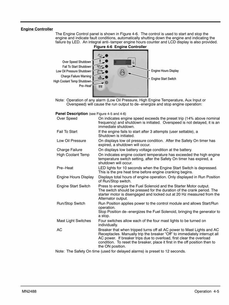
Engine ControllerThe Engine Control panel is shown in Figure 4-6. The control is used to start and stop theengine and indicate fault conditions, automatically shutting down the engine and indicating thefailure by LED. An integral anti−tamper engine hours counter and LCD display is also provided.
Figure 4-6 Engine Controller
Over Speed ShutdownFail To Start Shutdown
Low Oil Pressure Shutdown
Charge Failure Warning
High Coolant Temp ShutdownPre-Heat
Engine Start Switch
Engine Hours Display
Note: Operation of any alarm (Low Oil Pressure, High Engine Temperature, Aux Input orOverspeed) will cause the run output to de−energize and stop engine operation:
Panel Description (see Figure 4-5 and 4-6)Over Speed On indicates engine speed exceeds the preset trip (14% above nominal
frequency) and shutdown is initiated. Overspeed is not delayed, it is animmediate shutdown.
Fail To Start If the engine fails to start after 3 attempts (user settable), a Shutdown is initiated.
Low Oil Pressure On displays low oil pressure condition. After the Safety On timer hasexpired, a shutdown will occur.
Charge Failure On displays low battery voltage condition at the battery.High Coolant Temp On indicates engine coolant temperature has exceeded the high engine
temperature switch setting, after the Safety On timer has expired, ashutdown will occur.
Pre−Heat LED lights for 10 seconds when the Engine Start Switch is depressed.This is the pre heat time before engine cranking begins.
Engine Hours Display Displays total hours of engine operation. Only displayed in Run Positionof Run/Stop switch.
Engine Start Switch Press to energize the Fuel Solenoid and the Starter Motor output. The switch should be pressed for the duration of the crank period. Thestarter motor is disengaged and locked out at 20 Hz measured from theAlternator output.
Run/Stop Switch Run Position applies power to the control module and allows Start/Runoperation.Stop Position de−energizes the Fuel Solenoid, bringing the generator toa stop.
Mast Light Switches Four switches allow each of the four mast lights to be turned onindividually.
AC Breaker that when tripped turns off all AC power to Mast Lights and ACReceptacles. Manually trip the breaker “Off” to immediately interrupt allAC power. If breaker trips due to overload, first clear the overloadcondition. To reset the breaker, place it first in the off position then tothe ON position.
Note: The Safety On time (used for delayed alarms) is preset to 12 seconds.

4-6 Operation MN2488
WARNING: Light fixtures become extremely hot during use. To prevent severe burns, do not touch lightfixtures, bulbs or other components until they have cooled and no longer present a burn hazard.Wear protective clothing when placing the tower in the stowed position after use and do not allowany person to touch the light fixtures.
Caution: Careless handling or storage of the light fixtures can damage the fixtures, lenses, and/or bulbs.
POW’R LITE OperationTo prevent engine damage, the following checklist should be followed before starting the unit.
Caution: Do not overfill the engine oil. Serious damage to the engine can result from overfilling the oil.
Prestart Checklist:1. Unlock and open the engine compartment doors.2. Check the engine crankcase oil and add oil if required. Do not overfill.
Overfilling engine crankcase with oil can cause serious engine damage.WARNING: Engine coolant is under pressure and is near the boiling point of water when engine is hot.
Do not open the coolant system until the engine has completely cooled. Hot coolant cancause severe burns and other injuries. When engine is cool, coolant level can be checked.
3. Check the radiator coolant level and coolant if required. The radiator cap is accessibleby an opening in the rear panel of the engine compartment just below the Mast Lock.
4. Check and verify that battery cables are not corroded, not frayed and secure.5. Check diesel fuel level and add if necessary. Never allow the engine to run out of fuel.
Caution: Never start the engine with any of the lights on, or with any electrical load connected, asdamage to the light tower may result.
Caution: Do not operate preheat for more than 30 seconds or the heating element may be damaged.Caution: Do not engage the starter motor for more than 60 seconds at a time or damage may result.Caution: Never use explosive engine starting fluids. Please read the engine manual and unit placards
carefully before starting the engine. Starting fluids are not compatible with the preheat cycle.
Engine Start Procedure: (see Figure 4-6)1. Make sure all light and auxiliary switches are in the OFF position and that all loads are
disconnected.2. Place the Run/Stop switch in the Run Position. This applies power to the control.3. Observe the LEDs, they should be off. If Aux Input LED is on, the engine will not start.4. Press and hold the Engine Start switch to start the engine (energize the Fuel Solenoid
output, then the Starter Motor output. ) There is a 10 second pre−heat delay beforecranking begins. Hold the switch for the duration of the crank period (until the enginehas started. The starter motor is disengaged and locked out when a 20 Hz signal ismeasured from the Alternator output). After the starter motor has disengaged, the Safety On timer is activated (12 seconds),allowing Oil Pressure, High Engine Temperature and Charge Fail to stabilize withouttriggering the fault.
Note: If the generator has not started when the Engine Start switch is released or the enginestops after it was running, the Run/Start switch must be turned to STOP then back to theRun position before another start cycle can be performed.
5. After the engine starts, listen for unusual noises, “knocks”, or vibration. If anythingappears to be operating abnormally, shut the engine down immediately.
6. When the engine reaches operating speed and is operating smoothly, the lights may beturned on, one at a time, allowing a second between each switch.
7. Observe each floodlight for proper operation.

Operation 4-7MN2488
Flood Light Operation:1. When the engine reaches operating speed and is operating smoothly, turn on one light
and wait one second turn on another light and wait one second etc. until the flood lightsare all on.
2. Observe the operation of each flood light and replace defective bulbs if required. Tochange a bulb, refer to Section 5 of this manual.
Note: Vaporous flood lights may require 5 to 15 minutes to warm up and produce full light output.
Operating Checks:3. Check diesel fuel level and shut off the engine and add if necessary. Check engine oil
each time fuel is added. Never allow the engine to run out of fuel or to run low of oil.
Receptacle Panel Load Connections, see Figure 4-7.1. 120/240VAC voltage is present at the receptacle panel only when the light tower is
running.2. Carefully inspect all Individual load cables for broken insulation or other signs of
damage. Never use a damaged cable. Replace it before usage.3. Individual load cables may be routed to the receptacle compartment.4. Individual load cables may be connected or disconnected while generator is running.
Use extreme care not to touch any electrical wire or terminal to avoid shock hazard.5. Keep Engine Compartment doors closed at all times. This prevents rain or other
harmful elements from entering the compartment.
AC Breaker (on panel) that when tripped turns off all AC power to Mast Lights and ACReceptacles. Manually trip the breaker “Off” to immediately interrupt all AC power. If breaker trips due to overload, first clear the overload condition. To reset the breaker, place it first in the off position then to the ON position.
Figure 4-7 Receptacle Panel (Single Phase)
Test
Reset
GFCI Outlet120V, 20A
240V, 30A
YG
X
(FrontView)
NEMAL630R250V30A
Engine Stop Procedure: (see Figure 4-6)Caution: Never stop the engine with any of the lights on, or with any electrical load connected, as
damage may result.
1. Turn OFF all floodlight switches and unplug all loads from receptacle panel.Note: After turning OFF a light, do not attempt to turn the light ON until after a 10−25 minute cool
down period. Turning a light OFF then ON may damage the light bulb.2. If the engine has been operating for several hours under load, allow it to operate
unloaded for at least five minutes to reduce coolant temperature.3. Place the key switch in the STOP Position. This de−energizes the Fuel Solenoid,
bringing the generator to a stop and removes power from the control.
4-8 Operation MN2488
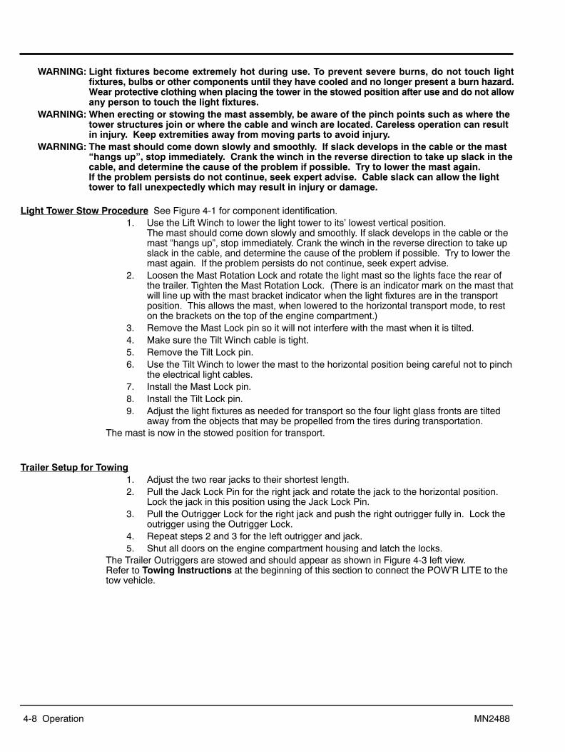
WARNING: Light fixtures become extremely hot during use. To prevent severe burns, do not touch lightfixtures, bulbs or other components until they have cooled and no longer present a burn hazard.Wear protective clothing when placing the tower in the stowed position after use and do not allowany person to touch the light fixtures.
WARNING: When erecting or stowing the mast assembly, be aware of the pinch points such as where thetower structures join or where the cable and winch are located. Careless operation can resultin injury. Keep extremities away from moving parts to avoid injury.
WARNING: The mast should come down slowly and smoothly. If slack develops in the cable or the mast“hangs up”, stop immediately. Crank the winch in the reverse direction to take up slack in thecable, and determine the cause of the problem if possible. Try to lower the mast again. If the problem persists do not continue, seek expert advise. Cable slack can allow the lighttower to fall unexpectedly which may result in injury or damage.
Light Tower Stow Procedure See Figure 4-1 for component identification.1. Use the Lift Winch to lower the light tower to its’ lowest vertical position.
The mast should come down slowly and smoothly. If slack develops in the cable or themast “hangs up”, stop immediately. Crank the winch in the reverse direction to take upslack in the cable, and determine the cause of the problem if possible. Try to lower themast again. If the problem persists do not continue, seek expert advise.
2. Loosen the Mast Rotation Lock and rotate the light mast so the lights face the rear ofthe trailer. Tighten the Mast Rotation Lock. (There is an indicator mark on the mast thatwill line up with the mast bracket indicator when the light fixtures are in the transportposition. This allows the mast, when lowered to the horizontal transport mode, to reston the brackets on the top of the engine compartment.)
3. Remove the Mast Lock pin so it will not interfere with the mast when it is tilted.4. Make sure the Tilt Winch cable is tight.5. Remove the Tilt Lock pin.6. Use the Tilt Winch to lower the mast to the horizontal position being careful not to pinch
the electrical light cables.7. Install the Mast Lock pin.8. Install the Tilt Lock pin.9. Adjust the light fixtures as needed for transport so the four light glass fronts are tilted
away from the objects that may be propelled from the tires during transportation.The mast is now in the stowed position for transport.
Trailer Setup for Towing1. Adjust the two rear jacks to their shortest length.2. Pull the Jack Lock Pin for the right jack and rotate the jack to the horizontal position.
Lock the jack in this position using the Jack Lock Pin.3. Pull the Outrigger Lock for the right jack and push the right outrigger fully in. Lock the
outrigger using the Outrigger Lock.4. Repeat steps 2 and 3 for the left outrigger and jack.5. Shut all doors on the engine compartment housing and latch the locks.
The Trailer Outriggers are stowed and should appear as shown in Figure 4-3 left view. Refer to Towing Instructions at the beginning of this section to connect the POW’R LITE to thetow vehicle.
Section 5Troubleshooting and Maintenance
Troubleshooting and Maintenance 5-1MN2488
WARNING: Before cleaning, inspecting, repairing, refueling or performing any maintenance, always be surethe engine has stopped and that all rotating parts have also stopped. After stopping, certaincomponents are still extremely hot so be careful not to get burned.
WARNING: Before servicing the light tower, be sure to disconnect the plug wires to help preventaccidental engine rotation or starting.
WARNING: Installation and servicing of batteries is to be performed or supervised by personnelknowledgeable of batteries and the required precautions. Keep unauthorized personnel awayfrom batteries.
WARNING: Disconnect the battery’s ground terminal before working in the vicinity of the battery orbattery wires. Contact with the battery can result in electrical shock when a tool accidentallytouches the positive battery terminal or wire. The risk of such shock is reduced when theground lead is removed during installation and maintenance.
Maintenance The following are general maintenance recommendations. The engine must be stopped and allelectrical load devices removed from the light tower plugs or terminals before any maintenance isperformed.
General Checks 1. Inspect the fuel system for leaks. Replace defective components immediately.2. Inspect and replace any fuel line that shows signs of deterioration.3. Inspect all fuel clamps to ensure they are tight and no leaks exist.4. Make sure the fuel cap fits snugly on the fuel tank and that the fuel tank does not leak.5. Inspect the condition of AC outlets for damage and replace if damaged.6. Test all GFCI (Ground Fault Circuit Interrupter) receptacles daily by pressing the test
button on the receptacle during operation. Ensure that the GFCI trips and and novoltage is present at the receptacle. Replace any GFCI receptacle that fails the test.
7. Inspect the external wire cables (extension cords) and connectors to be used for cuts,frayed insulation, or loose connections. Repair or replace any problems prior to usingthe unit.
8. Inspect bolts and nuts for tightness. Vibration can cause nuts or bolts to loosen.Change Engine Oil
Refer to engine manual for manufacturers recommendation for oil and filter change intervals andtype of oil to use and procedures.
Check Air Cleaner (Left side cover) Refer to engine manual for manufacturers recommendation for cleaning and replacementintervals and procedures.
Flood Light Bulb ReplacementWARNING: Light fixtures become extremely hot during use. To prevent severe burns, do not touch light
fixtures, bulbs or other components until they have cooled and no longer present a burn hazard.Wear protective clothing when placing the tower in the stowed position after use and do not allowany person to touch the light fixtures.
Refer to Section 4 of this manual for the procedures if you are not familiar with these steps.1. Stop the generator.2. Lower the mast.3. Tilt the mast down to the stowed position.4. Wait until the fixtures and bulbs have cooled sufficiently and replace the defective bulb.
5-2 Troubleshooting and Maintenance MN2488
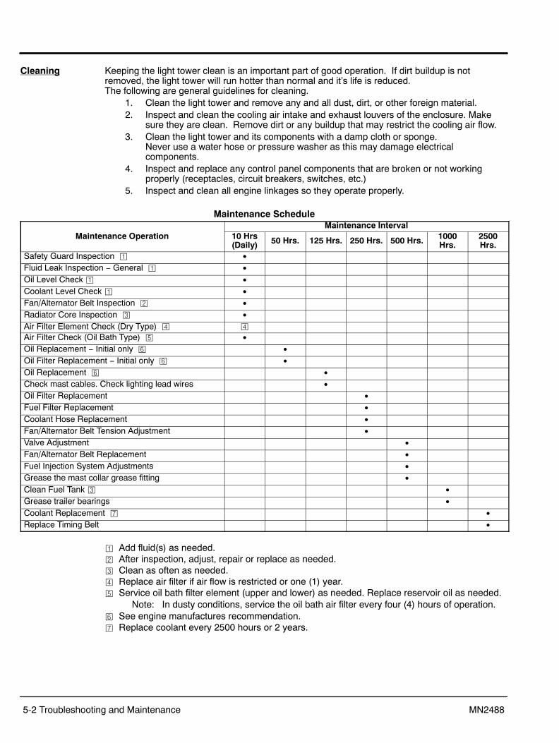
Cleaning Keeping the light tower clean is an important part of good operation. If dirt buildup is notremoved, the light tower will run hotter than normal and it’s life is reduced. The following are general guidelines for cleaning.
1. Clean the light tower and remove any and all dust, dirt, or other foreign material.2. Inspect and clean the cooling air intake and exhaust louvers of the enclosure. Make
sure they are clean. Remove dirt or any buildup that may restrict the cooling air flow.3. Clean the light tower and its components with a damp cloth or sponge.
Never use a water hose or pressure washer as this may damage electricalcomponents.
4. Inspect and replace any control panel components that are broken or not workingproperly (receptacles, circuit breakers, switches, etc.)
5. Inspect and clean all engine linkages so they operate properly.
Maintenance Schedule
Maintenance OperationMaintenance Interval
10 Hrs(Daily) 50 Hrs. 125 Hrs. 250 Hrs. 500 Hrs. 1000
Hrs.2500Hrs.
Safety Guard Inspection � �
Fluid Leak Inspection − General � �
Oil Level Check � �
Coolant Level Check � �
Fan/Alternator Belt Inspection � �
Radiator Core Inspection � �
Air Filter Element Check (Dry Type) � �
Air Filter Check (Oil Bath Type) � �
Oil Replacement − Initial only � �
Oil Filter Replacement − Initial only � �
Oil Replacement � �
Check mast cables. Check lighting lead wires �
Oil Filter Replacement �
Fuel Filter Replacement �
Coolant Hose Replacement �
Fan/Alternator Belt Tension Adjustment �
Valve Adjustment �
Fan/Alternator Belt Replacement �
Fuel Injection System Adjustments �
Grease the mast collar grease fitting �
Clean Fuel Tank � �
Grease trailer bearings �
Coolant Replacement �
Replace Timing Belt �
� Add fluid(s) as needed.� After inspection, adjust, repair or replace as needed.� Clean as often as needed.� Replace air filter if air flow is restricted or one (1) year.� Service oil bath filter element (upper and lower) as needed. Replace reservoir oil as needed.
Note: In dusty conditions, service the oil bath air filter every four (4) hours of operation.� See engine manufactures recommendation. Replace coolant every 2500 hours or 2 years.

Troubleshooting and Maintenance 5-3MN2488
POW’R LITE Troubleshooting GuideTable 5-1 Troubleshooting Guide
Problem Possible Cause RemedyMast will not raise to operating position. Mast Lock Pin still in place.
Defective winch or cable.Remove pin.Have winch and cable examined by a qualified mechanic. Replace if required.
Mast will not telescope to desired height. Defective winch or broken cable. Have winch and cable examined by a qualified mechanic. Replace if required.
Mast will not rotate. Bolt/nut on bottom of mast may be tootight.Mast rotation collar needs to be greased.
Back off on nut setting slightly and try to rotate mast.
Apply grease to grease fitting.Engine will not turn over. Loose battery cables or dead battery.
Engine seized due to loss of oil.
Recharge or replace battery. Check battery cable at batteryterminals and starter for tightness.Have unit inspected by qualified mechanic.
Engine turns over but will not start. Fuel tank empty.Clogged fuel filter.Fuel line connections leaking.Heater plug element burned out.Suspect contaminated fuel.
Fill tank and bleed fuel system.Replace filter, use winter grade fuel (weather cold). Bleed out air.Tighten all fuel fittings and bleed air from fuel system.Replace heater plug.The fuel tank has a drain valve on the bottom side of the trailer.Drain and replace the fuel.
Engine difficult to start. Battery charge low or cables loose.Motor oil too thick in cold winter.Clogged fuel filter or fuel cloudy in coldweather.Fuel line connections leaking.
Replace/recharge battery. Tighten cable connections.Use proper winter grade oil.Replace filter and bleed air from System. Use winter grade diesel incold weather.Tighten all fuel fittings and bleed air from fuel system.
Rough running engine with low poweroutput.
Clogged fuel filter or leaking fuel lineconnections.Exhaust system clogged.Air filter clogged.Fuel injectors nozzles clogged or stuck.Valve clearance needs adjusting or valvesprings broken.Governor or injector pump defective.
Tighten all fuel fittings and bleed air from fuel system.
Check muffler and exhaust manifold, clear any obstructions.Replace air filter.Have unit checked by qualified mechanic.Have unit checked by qualified mechanic.
Have unit checked by qualified mechanic.
Engine runs but produces excessive thicksmoke.
Crankcase oil level too high.Compression low.
Drain oil level to full mark on dipstick.Have qualified mechanic check unit for broken or seized rings orimproper valve clearances.
Engine runs but battery voltage low. Battery charger or alternator failure. Have qualified mechanic repair or replace.Engine runs but lights do not come on. Circuit breakers tripped or light switches
in "OFF" position.Loose connections in light wiring.Loose connection in ballast box wiring.Bulbs burned out.Defective AC generator.Engine speed too low.
Defective ballast.
Check circuit breaker, press reset button if tripped, turn on lightswitches.Check junction box connections for security.Have a trained electrician inspect ballast box and wiring.Replace bulbs.Have a trained electrician inspect generator.Have a qualified mechanic check unit and, if necessary, resetengine speed to 1800 RPM or 60 HZ.Have a trained electrician inspect the ballast system.
Unusual noises coming from thegenerator.
Generator bearing or cooling fandefective.
Have a qualified mechanic inspect the generator.
An electric shock occurs when the lighttower or housing is touched.
Short circuit in wiring system. IMMEDIATELY stop using the light tower.IMMEDIATELY have the unit inspected by a qualified mechanic.
Control panel does not illuminate Battery power failure Check control fuse, replace if necessary.Replace or recharge battery.Tighten cable connections.

5-4 Troubleshooting and Maintenance MN2488
Figure 5-8 Flood Light Mast Wiring
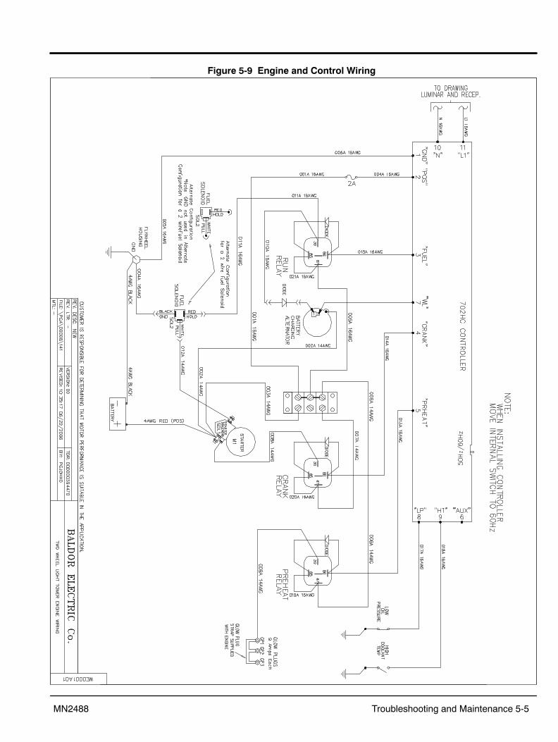
Troubleshooting and Maintenance 5-5MN2488
Figure 5-9 Engine and Control Wiring

5-6 Troubleshooting and Maintenance MN2488


Baldor District Offices
© Baldor Electric CompanyMN2488
All Rights Reserved. Printed in USA12/09
WARNING:CALIFORNIA PROPOSITION 65 WARNING:
Engine exhaust from this product contains chemicals knownto the state of California to cause cancer, birth defects andother reproductive harm.
WARNING:CALIFORNIA PROPOSITION 65 WARNING:
Battery posts, terminals and related accessories are known tothe state of California to cause cancer, birth defects and otherreproductive harm.
BALDOR ELECTRIC COMPANYP.O. Box 2400
Ft. Smith, AR 72901−2400(479) 646−4711
Fax (479) 648−5792