Piping Workflow for MEP AutoCAD Piping Phil Nower – Hazen and Sawyer MP3512-L: In this class we will harness the power of MEP Data in AutoCAD. We will review the workflow to fully utilize this Data throughout the projects life cycle, from the Design Team to the Construction Team. We will use the Data to help build a process mechanical piping design, share that data with the entire Project Design Team. Review how the Design Team can access and analyze the Data using Navisworks and Spread Sheets to increase communication and facilitate efficient project workflow. Then we will bring the Process Design and the Data into a construction environment. Where along with developing spool and fabrication drawings we will increase and build on the Data from the Design Team to produce a powerful as built model with up to date Data. Learning Objectives At the end of this class, you will be able to: 1) Apply BIM Data in the Design ....................................................................................2 2) Build on the Design using Manufactures Data .........................................................4 3) Produce Fabrication Drawings Directly from the Design .........................................5 4) Bring Data into other files ..........................................................................................6 5) Developing a Good BIM Plan Enhances Productivity ............................................10 About the Speaker Phil Nower has been using 3D modeling from 1989 to the present. He started to produce parametric spreadsheet-driven 3D models with Mechanical Desktop R14 for the petroleum and chemical industries. When he became employed by Hazen and Sawyer, he had the opportunity to use AutoCAD MEP software to build two large-scale water treatment plants, as well as small scale pump stations. All of these 3D projects required some sort of customization to the AutoCAD MEP out-of-the-box 3D content to meet the design challenges for the above-stated projects, from adding sizes to existing fittings to producing specialized parametric equipment [email protected]

Welcome message from author
This document is posted to help you gain knowledge. Please leave a comment to let me know what you think about it! Share it to your friends and learn new things together.
Transcript

Piping Workflow for MEP AutoCAD Piping Phil Nower – Hazen and Sawyer
MP3512-L: In this class we will harness the power of MEP Data in AutoCAD. We will review the workflow to fully utilize this Data throughout the projects life cycle, from the Design Team to the Construction Team. We will use the Data to help build a process mechanical piping design, share that data with the entire Project Design Team. Review how the Design Team can access and analyze the Data using Navisworks and Spread Sheets to increase communication and facilitate efficient project workflow. Then we will bring the Process Design and the Data into a construction environment. Where along with developing spool and fabrication drawings we will increase and build on the Data from the Design Team to produce a powerful as built model with up to date Data.
Learning Objectives
At the end of this class, you will be able to:
1) Apply BIM Data in the Design ....................................................................................2
2) Build on the Design using Manufactures Data .........................................................4
3) Produce Fabrication Drawings Directly from the Design .........................................5
4) Bring Data into other files ..........................................................................................6
5) Developing a Good BIM Plan Enhances Productivity ............................................10
About the Speaker
Phil Nower has been using 3D modeling from 1989 to the present. He started to produce parametric
spreadsheet-driven 3D models with Mechanical Desktop R14 for the petroleum and chemical industries.
When he became employed by Hazen and Sawyer, he had the opportunity to use AutoCAD MEP
software to build two large-scale water treatment plants, as well as small scale pump stations. All of
these 3D projects required some sort of customization to the AutoCAD MEP out-of-the-box 3D content to
meet the design challenges for the above-stated projects, from adding sizes to existing fittings to
producing specialized parametric equipment

Piping Workflow for AutoCAD MEP – MP3512-L
2
1) Apply BIM Data in the Design
Properties
Dialog Box
Extended
Data Tab
Properties
Dialog Box
Properties
Dialog Box
Add
Property
Sets Icon
All Property Sets that
can be imported into
the selected object
To down load the Property Set Data into an object you first must select it. Then
go to the (Extended Data) Tab in the Properties dialog box. Select the Add
Property Sets icon, in the lower left corner. The Add Property Sets Dialog Box
will appear. All of the Property Sets that can be imported into the selected
object will be visible. This gives you the option to select the data that you want
to be imported into the object.
The Property
Sets visible in
the Extended
Data Tab can
now be read by
MEP Schedules,
and then
exported out to
Excel Spread
Sheets.
Help Tip!
To save time in selecting
objects, Select Similar
with objects that share
common Property Sets.
Selected Object

Piping Workflow for AutoCAD MEP – MP3512-L
3
Excel Spread Sheet
Property Sets – Property Set Definitions
The (Applies To) Tab
determines the Object/s.
In the (Definition) Tab are the values
for the Property Sets that are added
to the (Extended Data) Tab.
Property Set Definitions can be
accessed, edited and created through
the Style Manager Dialog Box, which
can be found in Style & Display in the
Manage area of the Ribbon.
Property Set Definitions
are under
Documentation Objects
Once a
Set is
selected,
you will
see tabs
that
control it.
Schedules, Quantity Take-Off, Exporting to Excel Spread Sheets
MEP Pipe Schedule
MEP Schedules read the imported Property Sets
Heads Up! The Objects
that do not have the
Property Set data
imported will have a ? in the column
instead of a value.
MEP Schedules can be found on the Annotation area of the Ribbon and on the Tool Palettes.
Schedules can be read objects in the same dwg file
or they can read objects from an external source.
The MEP Schedule can be exported as an Excel Spread Sheet, providing the
team access to the information.
Piping Workflow for AutoCAD MEP – MP3512-L
4
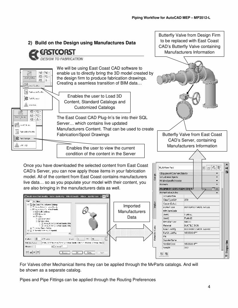
2) Build on the Design using Manufactures Data
Butterfly Valve from Design Firm
to be replaced with East Coast
CAD’s Butterfly Valve containing
Manufacturers Information
Butterfly Valve from East Coast
CAD’s Server, containing
Manufacturers Information
We will be using East Coast CAD software to enable us to directly bring the 3D model created by the design firm to produce fabrication drawings. Creating a seamless transition of BIM data…
Enables the user to Load 3D
Content, Standard Catalogs and
Customized Catalogs
Enables the user to view the current
condition of the content in the Server
The East Coast CAD Plug-In’s tie into their SQL
Server… which contains live updated
Manufacturers Content. That can be used to create
Fabrication/Spool Drawings
For Valves other Mechanical Items they can be applied through the MvParts catalogs. And will
be shown as a separate catalog.
Pipes and Pipe Fittings can be applied through the Routing Preferences
Once you have downloaded the selected content from East Coast
CAD’s Server, you can now apply those items in your fabrication
model. All of the content from East Coast contains manufacturers
live data… so as you populate your model with their content, you
are also bringing in the manufacturers data as well.
Imported
Manufacturers
Data

Piping Workflow for AutoCAD MEP – MP3512-L
5
3) Produce Fabrication Drawings Directly from the Design
Once the items, pipes, pipe fittings have been updated… producing spool drawings from them using the plug-ins is pretty straightforward and simple. However… even though the steps are simple the implications cannot be under appreciated. In a more traditional approach to developing project drawings, there were several distinct sets of drawings in a projects life cycle, that for the most part were only linked together with notes, annotation, field memos, etc…
Design Coordination Spool As Built
Project Drawings
Now that we have the ability to use the Manufacturers data directly into the design model this enables us to have the coordination drawings, spool drawings and the as built drawings all produced together. Radically changing our workflow…
Design Coordination Spool As Built
Project Drawings
Opens up the
Fabrication Palette
To start a spool
right click on the
highlighted area
and select Define.
Now select the objects that you wish to be in the spool drawing. You can have more than one spool indicated in a drawing.
Note: A very nice safety valve! You can’t
select objects to be spooled twice.
The “spool” icon indicates
when the items have been
selected to be spooled.
To produce a spool
drawing, right click the
spool icon and select
Generate
Now select Open to
view the created spool
drawing.
Generated Spool Drawing
with BOM

Piping Workflow for AutoCAD MEP – MP3512-L
6
4) Bring Data into other files
Bringing Data into 2D and 3D DWF Files…
In order to see the Property Sets in a 2D or 3D DWF file you must fist go to the
AEC DWF Publishing Options
This dialog box looks for the AutoCAD Publish
Properties List File. You can make your own, or edit the
Out of Box one. However this file does not see the
Property Sets that are currently in the open dwg file. To make sure that you’re gonna see the
Property Sets in your DWF files select
Add. That will bring up the Add Property
Sets dialog box.
This dialog box sees
only the Property Sets
that are in
the drawing file
that is
currently open Make sure that the Publish Property Set Data is
checked. You can select both… but at least
make sure that the first one is checked.

Piping Workflow for AutoCAD MEP – MP3512-L
7
To produce a 2D DWF File go to Export – DWF
Once the AEC DWF Publishing Options has been modified your 2D and 3D DWF Files now contains Object Orientated
Property Data Sets. You can now apply this additional information to your BIM Plan, helping to clarify designs by
not relaying entirely on annotation and aiding in documenting the design process.
To produce a 3D DWF File go to Export – 3D DWF
If you adopt bringing Object Orientated Property Data Sets into how the project is documented from design to constructions to facility management, the Property Data Sets will be populated
with the manufacturers’ data. This can be a useful tool in developing a comprehensive Project BIM Plan.
Data from
Object
Data from Object
Piping Workflow for AutoCAD MEP – MP3512-L
8
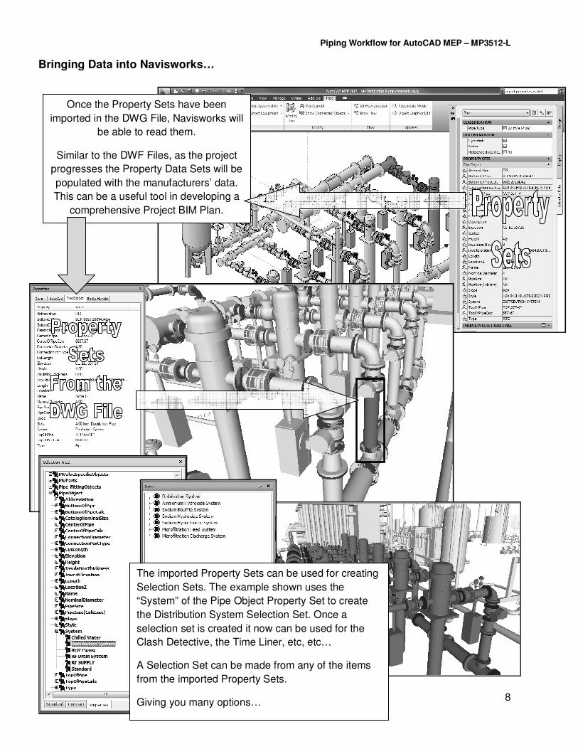
Bringing Data into Navisworks…
Once the Property Sets have been
imported in the DWG File, Navisworks will
be able to read them.
Similar to the DWF Files, as the project
progresses the Property Data Sets will be
populated with the manufacturers’ data.
This can be a useful tool in developing a
comprehensive Project BIM Plan.
The imported Property Sets can be used for creating
Selection Sets. The example shown uses the
“System” of the Pipe Object Property Set to create
the Distribution System Selection Set. Once a
selection set is created it now can be used for the
Clash Detective, the Time Liner, etc, etc…
A Selection Set can be made from any of the items
from the imported Property Sets.
Giving you many options…
Piping Workflow for AutoCAD MEP – MP3512-L
9
Revit Project
DWG File
DWG File
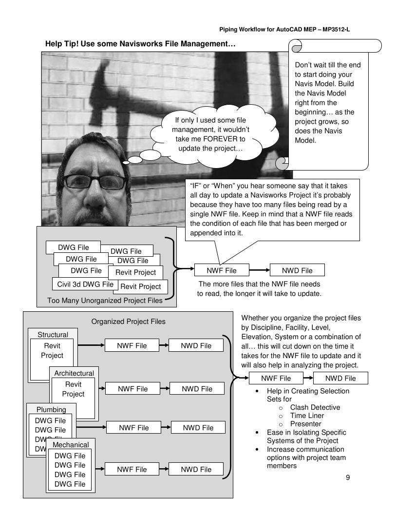
Help Tip! Use some Navisworks File Management…
If only I used some file
management, it wouldn’t
take me FOREVER to
update the project…
NWF File
DWG File
DWG File
DWG File
Civil 3d DWG File
NWD File Revit Project
“IF” or “When” you hear someone say that it takes
all day to update a Navisworks Project it’s probably
because they have too many files being read by a
single NWF file. Keep in mind that a NWF file reads
the condition of each file that has been merged or
appended into it.
Too Many Unorganized Project Files
The more files that the NWF file needs
to read, the longer it will take to update.
Structural
Revit
Project
Architectural
Revit
Project
Plumbing
DWG File
DWG File
DWG File
DWG File Mechanical
DWG File
DWG File
DWG File
DWG File
NWF File NWD File
NWF File NWD File
NWF File NWD File
NWF File NWD File
NWF File NWD File
Organized Project Files Whether you organize the project files
by Discipline, Facility, Level,
Elevation, System or a combination of
all… this will cut down on the time it
takes for the NWF file to update and it
will also help in analyzing the project.
• Help in Creating Selection Sets for
o Clash Detective o Time Liner o Presenter
• Ease in Isolating Specific Systems of the Project
• Increase communication options with project team members
Don’t wait till the end
to start doing your
Navis Model. Build
the Navis Model
right from the
beginning… as the
project grows, so
does the Navis
Model.

Piping Workflow for AutoCAD MEP – MP3512-L
10
5) Developing a Good BIM Plan Enhances Productivity
Design Firms 3D Project
BIM Data
Design Firm Contractor
Owner
In this Lab we are focusing on developing a seamless transfer of data from the design firm to the contractor, however this does naturally lead into understanding the need to produce a more comprehensive plan, one that covers the transfer of data from the design firm to the owner. A well thought out plan should have the BIM Data meeting the needs and requirements of all three phases of the project.
BIM Data BIM Data
Contract Drawings Interferences Quantity Take-Offs Design Analyzes Energy Requirements Schedules
Fabrication Drawings Construction Sequencing – 4D Coordination Staging Options
Training Personnel O&M Manuals Work Orders Maintenance Planning Proposed Work
3D MEP Models
Schedule DWG Files
Excel Spread Sheets
Contractors 3D Project
3D MEP Models
Schedule DWG Files
Excel Spread Sheets
If we use today’s Lab as one example of how a Good BIM Plan enhances productivity, where we took the design firms 3D Model/Data and transferred it to the Contractor. There was no need to re-work the project hierarchy. The naming conventions stayed the same. The methods in which the data was extracted from the 3D Model to the spread sheets didn’t change. The transition from Design Firm to Contractor was seamless because an attempt was made not to duplicate work. Keep in mind that today’s lab focuses on just one example of applying a BIM Plan. Every single aspect of a 3D project has the potential to be planned out throughout the life cycle of the project. The more effort, items, variables that you put into developing a BIM Plan, from CAD Standards to Engineering Cals to Permits the less work will need to be re-done.
Related Documents