PIPING SYSTEM

Welcome message from author
This document is posted to help you gain knowledge. Please leave a comment to let me know what you think about it! Share it to your friends and learn new things together.
Transcript

PIPING SYSTEM
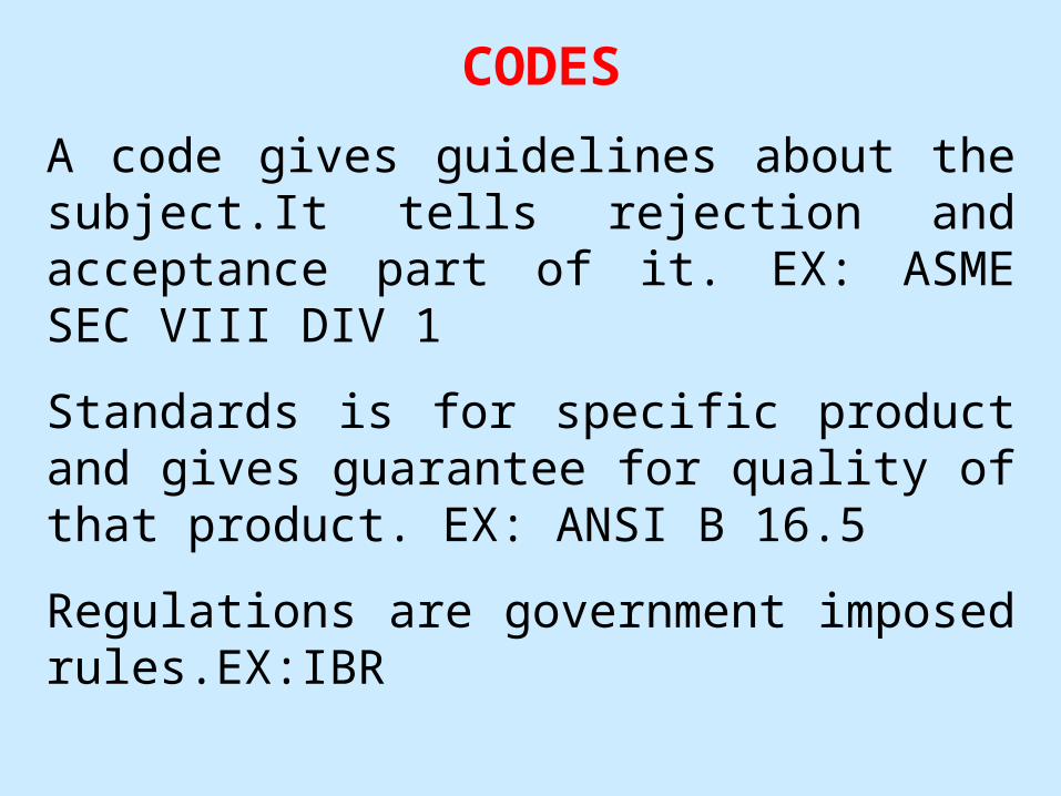
CODES
A code gives guidelines about the subject.It tells rejection and acceptance part of it. EX: ASME SEC VIII DIV 1
Standards is for specific product and gives guarantee for quality of that product. EX: ANSI B 16.5
Regulations are government imposed rules.EX:IBR
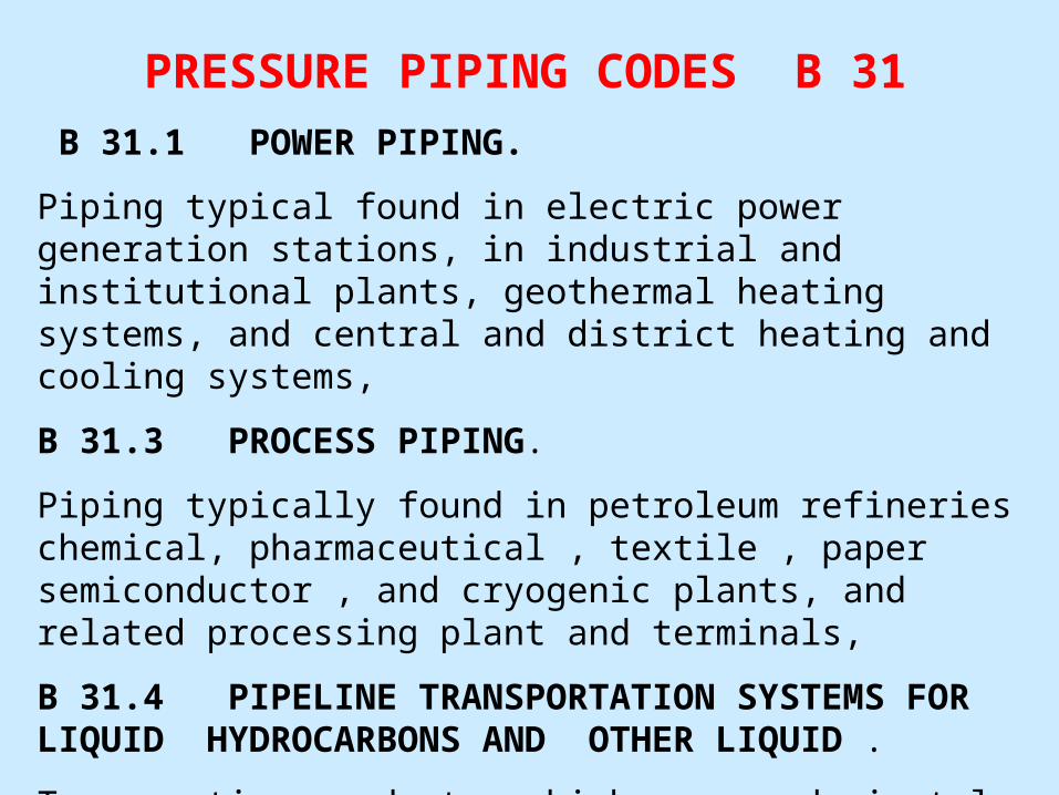
PRESSURE PIPING CODES B 31
B 31.1 POWER PIPING.
Piping typical found in electric power generation stations, in industrial and institutional plants, geothermal heating systems, and central and district heating and cooling systems,
B 31.3 PROCESS PIPING.
Piping typically found in petroleum refineries chemical, pharmaceutical , textile , paper semiconductor , and cryogenic plants, and related processing plant and terminals,
B 31.4 PIPELINE TRANSPORTATION SYSTEMS FOR LIQUID HYDROCARBONS AND OTHER LIQUID .
Transporting products, which are predominately liquid between plants and terminal and within terminals, pumping ,and metering stations.

B 31.5 REFRIGERATION PIPING.
Piping for refrigeration and secondary coolants.
B 31.8 GAS TRANSPORTATION AND DISTRIBUTION PIPING SYSTEMS.
Piping transporting product which are predominately gas between sources and terminals.including compressor, regulating,and metering station, and gas gathering pipelines,
B 31.9 BUILDING SERVICES PIPING.
Piping typically found in industrial ,institutional,commercials,and public building and in multi-unit residences
B 31.11 SLURRY TRANSPORTATION PIPING SYSTEM
Piping transporting aqueous slurries between plants and terminal,and within terminal and within terminal, pumping, and regulating stations.

SCOPE OF B31.3a) This Code prescribes requirements for Materials and
components, design, fabrication, assembly, erection, examination, inspection, and testing of piping.
b) This code applies to piping for all fluids, including:
1) Raw, intermediate, and finished chemicals;
2) Petroleum products;
3) Gas, steam, air, and water;
4) Fluidized solids;
5) Refrigerants;
6) Cryogenic fluids (-151o to –425oF).

EXCLUSIONS OF B31.3This code excludes following:• Piping systems design for internal gauge pressures at or above
zero but less than 105kPa (15psi), provided the fluid handled is nonflammable, nontoxic, and not damaging to human tissue and its design temperature is from –29oC (-20oF) through 186oC (366oF);
• Power boiler s in accordance with BPV code Section-I and boiler external piping which is required to confirm to B31.1
• Tubes, tube headers, crossovers, and manifolds of fired heaters, which are internal to the heater enclosure; and
• Pressure vessels, heat exchangers, pumps, compressors, and other fluid handling or processing equipment, including internal piping and connections for external piping.
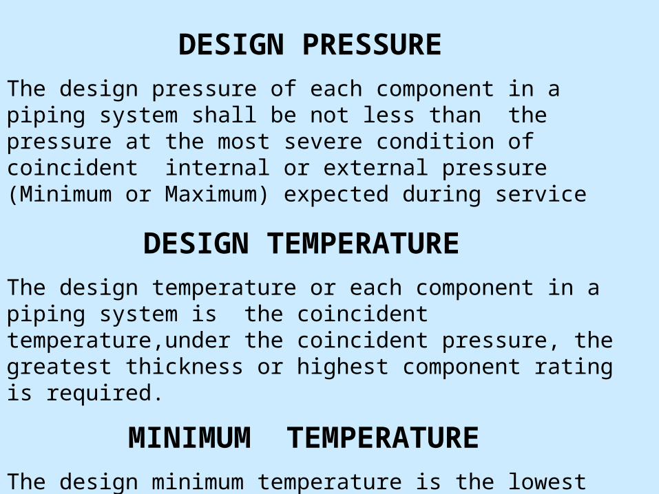
DESIGN PRESSURE
The design pressure of each component in a piping system shall be not less than the pressure at the most severe condition of coincident internal or external pressure (Minimum or Maximum) expected during service
DESIGN TEMPERATURE
The design temperature or each component in a piping system is the coincident temperature,under the coincident pressure, the greatest thickness or highest component rating is required.
MINIMUM TEMPERATURE
The design minimum temperature is the lowest component temperature expected in service.

FLUID CATEGORY ON B 31.3
CATEGORY D
A) The fluid handled is non flammable,non toxic ,and not damaging to human tissues.
B) The design gauge pressure does not exceed 150 Psi and temperature is from –29 c to 186 c.
C) Example water,air.(testing of the system not stringent.)
CATEGORY M
A fluid service in which the potential for personnel exposure is judged to be significant and in which a single exposure to a very small quantity of a toxic fluid,caused by leakage,can produce serious irreversible harm to persons on breathing or bodily contact, even when prompt restorative measures are taken.
Example .H2 SO4, CL2 Gas (Thread flanges are not recommended. Low pressure testing is also one of the requirement.

HIGH PRESSURE FLUID SERVICE –K CATEGORY
If the pressure is in excess of 2500 rating for specified design temperature and material group.
NORMAL FLUID SERVICE.
A fluid service pertaining to most piping covered by this code ie not subject to the rules for category D,category M or high pressure fluid service.

PIPE UNDER INTERNAL PRESSURE
• For t<D/6, the internal pressure design thickness for straight pipe shall be not less than that calculated below
t = PD 2(SE + PY)
• The minimum thickness T for the pipe selected, considering manufacturer’s minus tolerance, shall be not less than tm..
tm = t + cWhere,
tm = minimum required thickness including mechanical, corrosion, and erosion allowances.t = pressure design thickness

PIPE UNDER INTERNAL PRESSURE
c = the sum of the mechanical allowance plus corrosion and erosion allowances.
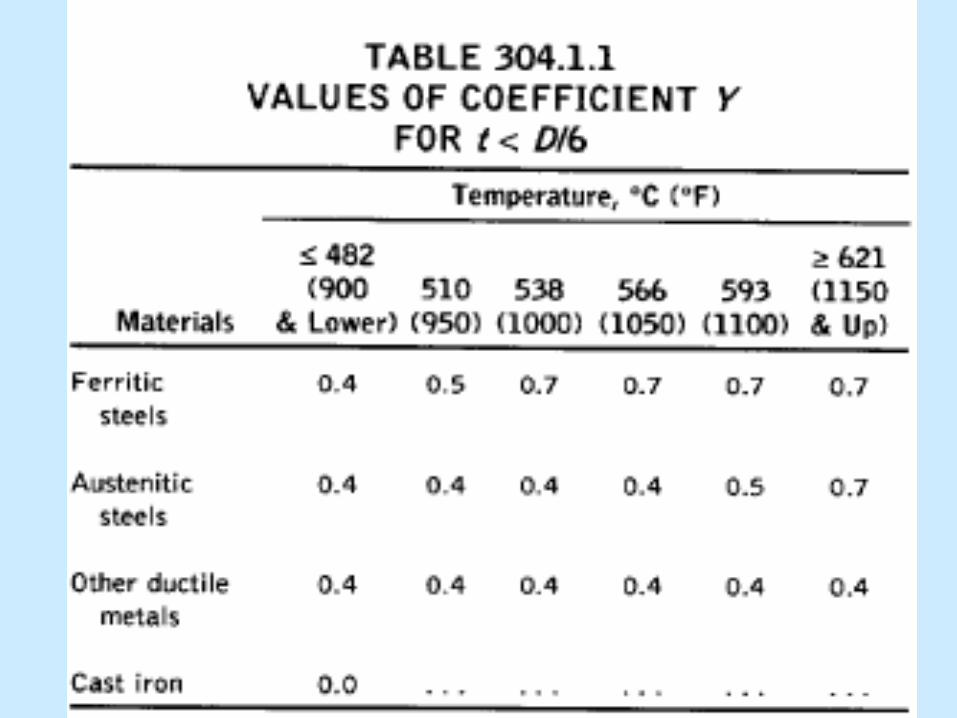
T = Pipe wall thicknessP = internal design gauge pressureD = outside diameter of the pipeE = quality factor from Table A-1A or A-1BS = stress value for material form Table A-1Y = Coefficient from Table 304.1.1, valid for t < D/6 and for
material shown. The value of Y may be interpolated for intermediated temperatures.

NPS- A dimension less designator of pipe .It indicates standard pipe size when followed by the specific size designation number with out an inch symbol (eg NPS 2, NPS 12)
NORMALISING- A process in which a ferrous metal is heated to a suitable temperature above the transformation range and is subsequently cooled in still air at room temperature.
POST HEATING- The application of heat to a fabricated or welded section subsequent to a fabrication, welding or cutting operation. Post heating ,or the entire assembly may be post heated in a furnace.
POST WELD HEAT TREATMENT- Any heat treatment subsequent to welding.
PREHEATING- The application of heat to a base metal immediately prior to a welding or cutting operation.
Galvanizing – A process by which the surface of iron or steel is covered with a layer of zinc

PREHEATING
Preheating is used, along with heat treatment, to minimize the detrimental effects of high temperature and severer thermal gradients inherent in welding.
Requirement and recommendations : Required and recommended minimum preheat temperatures for materials of various P-Numbers are given in table. If the ambient temperature is below 0oC (32oF), the recommendation become requirements.
Preheat Zone : Preheat zone shall extend at least 25mm (1in.) beyond each edge of the weld.

HEAT TREATMENT
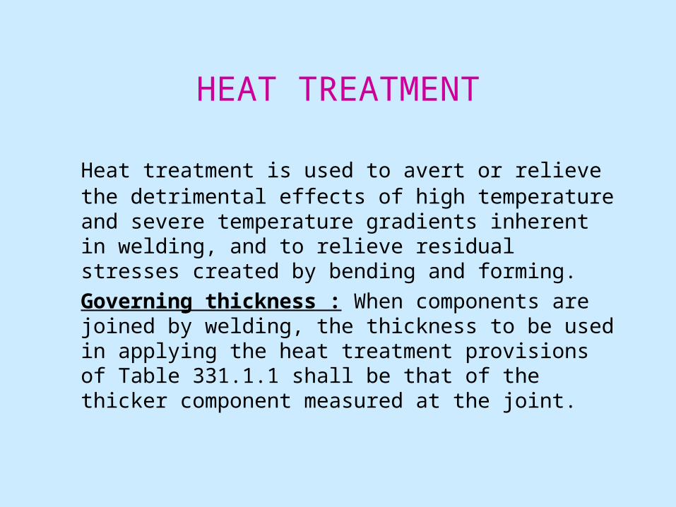
Heat treatment is used to avert or relieve the detrimental effects of high temperature and severe temperature gradients inherent in welding, and to relieve residual stresses created by bending and forming.
Governing thickness : When components are joined by welding, the thickness to be used in applying the heat treatment provisions of Table 331.1.1 shall be that of the thicker component measured at the joint.


BLOCK DIAGRAM OF DETAILED ENGINEERING
BID DOCUMENT
EQUIPMENT LAYOUT
PIPING GENERAL ARRANGEMENT
MATERIAL TAKE OFF
PURCHASE SPECIFICATION
PIPE SUPPORTGAD
PIPE SUPPORT
PRE-CONSTRUCTION SURVEY
INSTALLATION
ISOMETRIC DRAWINGS
FABRICATION DRAWINGS
FABRICATION DRAWINGS
PRE-ENGINEERING SURVEY

PROCESS FLOW DIAGRAM (PFD)
- BLOCK DIAGRAM SHOWS UNIT OPERATIONS AND
UNIT PROCESSES INVOLVED.
-SHOWS ALL MAJOR EQUIPMENT AND MAIN PIPING
AND ITS FLOW. BASED ON THIS PROCESS FLOW
DIAGRAM ENGINEER PREPARES PIPING &
INSTRUMENTION DIAGRAM.

TYPICAL SCHEMATIC OF PROCESS LINE.

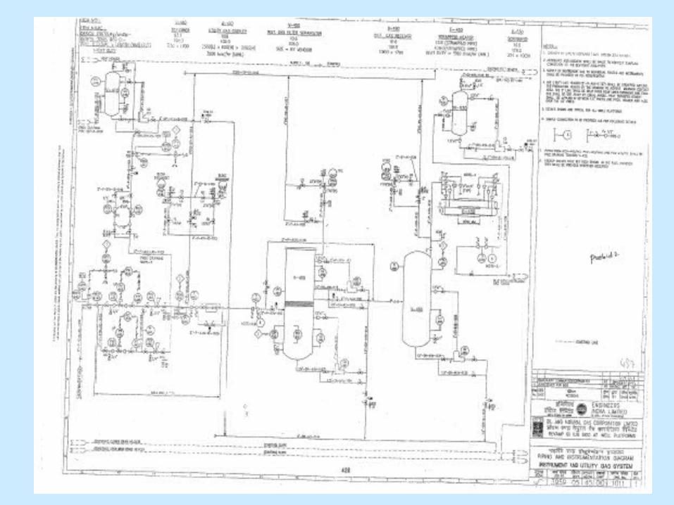
PIPING & INSTRUMENTATION DIAGRAM
THIS IS A DETAILED DIAGRAM WHICH IS DEVELOPED BASED ON PROCESS FLOW DIAGRAM. IN THIS DIAGRAM ONE WILL COME TO KNOW ABOUT THE EXACT NUMBER OF FLUID SERVICES INVOLVED APART FROM MAIN PROCESS FLUID. ALSO THIS DIAGRAM WILL HELP PIPING ENGINEER IN DEVELOPING HIS PIPING ARRANGEMENT.
THE INFORMATION WHICH THIS DIAGRAM WILL PROVIDE TO PIPING IS
- CONNECTING POINTS OF THE PIPE
-SIZE OF PIPE
- MATERIAL CLASS OF PIPE

- FLUID SERVICE OF THE PIPE - UNIQUE LINE IDENTIFICATION NUMBER
- INSULATION
- CONNECTING POINTS OF A PIPE
-VALVES, INSTRUMENTS AND SPECIALITIES INVOLVED IN THE PIPELINE.
- PRESSURE, TEMPERATURE FOR THE EQUIPMENTS.
-ALWAYS A P&ID IS ACCOMPANIED WITH LEGEND P&ID IN WHICH ALL SYMBOLS (USED IN P&ID) ARE EXPLAINED.


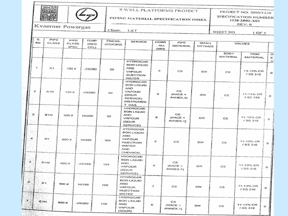
LINE NUMBER DESIGNATION –
1.5”-DH-A1N-1129-
SIZE LINE NUMBER
FLUID SERVICE
MATERIAL CLASS

LINE LISTPROVIDES SUMMARY OF ALL PROCESS PARAMETERS OF SYSTEM. IT IS PREPARED FROM P&ID.
PROVIDES INFORMATION ON :
- LINE NUMBER - FLUID IN SYSTEM -- SERVICE CLASS - HEAT TRACING- PAINTING - LINE SIZE- FLUID PHASE- OPERATING & DESIGN PRESSURE , TEMPERATURES- STRESS RELIEVING REQUIREMENT- RADIOGRAPHY REQUIREMENT- PWHT REQUIREMENT- TEST FLUID & TEST PRESSURE- INSULATION REQUIREMENT

LINE LIST
EQUIPMENT LAYOUT
THIS DIAGRAM INDICATES THE POSITION OF EQUIPMENT IN THE PLANT. ALL EQUIPMENTS ARE LOCATED WITH THEIR CO-ORDINATES OR THEY ARE LOCATED FROM GRID REFERENCE POINTS. FOR EACH EQUIPMENT ITS TAG NUMBER IS ATTACHED. THIS DRAWING IS PREPARED BY PIPING ENGINEER WITH THE HELP OF PROCESS ENGINEER
PIPING ENGINEER FURTHER DEVELOPS HIS GENERAL ARRANGMENT DIAGRAM BASED ON THIS.


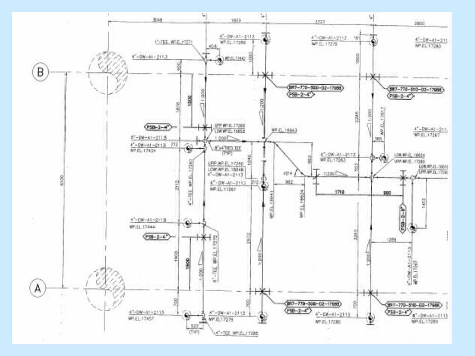
PIPING GENERAL ARRANGEMENT DIAGRAM
THIS DIAGRAM SHOWS THE ROUTING OF PIPE AS PER THE P&ID WITH RESPECT TO EQUIPMENT AND EXISTING STRUCTURE.
INFORMATION PROVIDED :
- EQUIPMENT LOCATION & ORIENTATION
- LINES WITH LINE NUMBERS
- INSTRUMENT TAG
- ROUTING OF PIPE BETWEEN EQUIPMENTS
- LOCATION OF EXISTING EQUIPMENT & INTERCONNECTING PIPING
- ELEVATION OF PIPE LINES


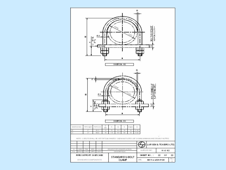
PIPING SUPPORT GAD
- SHOWS TYPES OF SUPPORT AND THEIR LOCATIONS IN THE PIPE LINE
- REFER STANDARD PIPE SUPPORT SKETCHES - GIVEN BY CONSULTANT
- THERE CAN BE SPECIAL TYPE OF SUPPORTS ALSO.

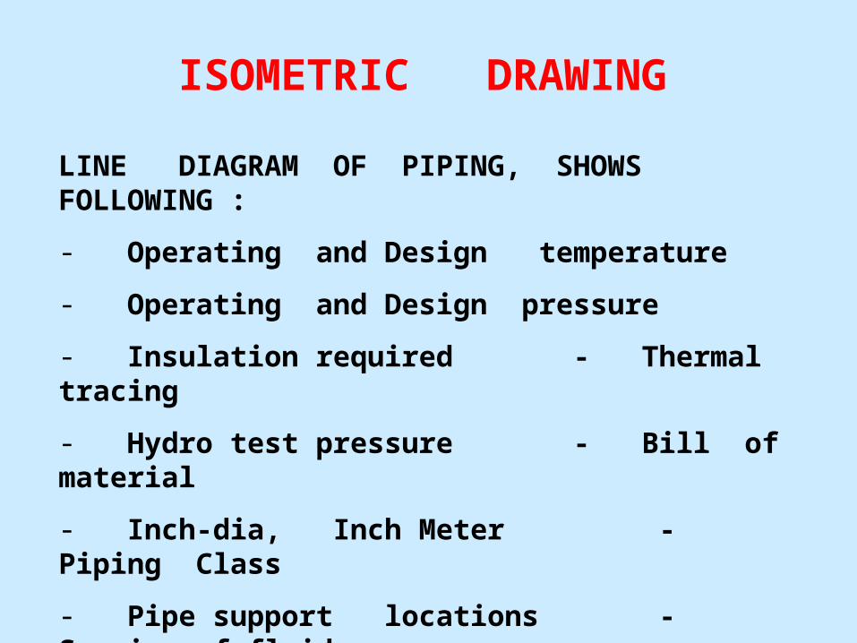
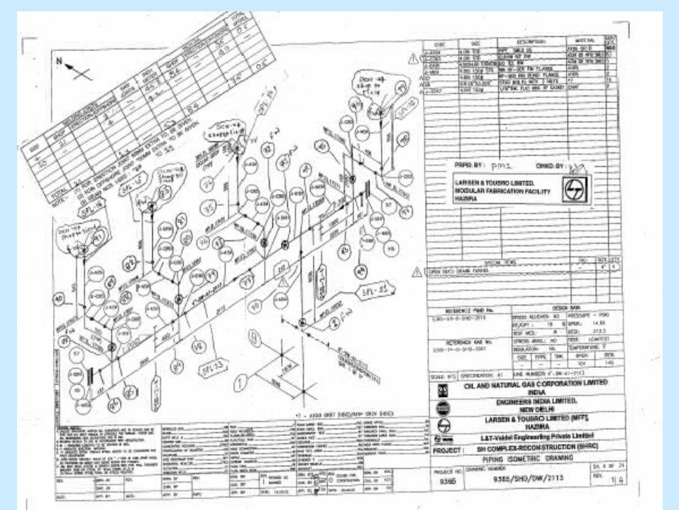
ISOMETRIC DRAWING
LINE DIAGRAM OF PIPING, SHOWS FOLLOWING :
- Operating and Design temperature
- Operating and Design pressure
- Insulation required - Thermal tracing
- Hydro test pressure - Bill of material
- Inch-dia, Inch Meter - Piping Class
- Pipe support locations - Service of fluid
- Points of weld, its marking - Pipe support type

1) Numbering of shop joint & offshore joints in successive numbers2) Numbering of spool according to the individual spools3) Check the BOM according to the item no.,inch,schedule&description 4) According to the pipe size,the no.of shop,offshore joints are added in the table inside the isometric.5) Inch meter,inch dia is calculated6) Inch meter =pipe length in meter x pipe size in inch7) Inch dia =pipe size in inch x no.of joints8) No.of spools are noted in the table9) For the continuing sheets,the numbering of shop joints,offshore & spool numbers will also be continuous.
Activities in ISO’S

PIPE SUPPORTS
- PROVIDE SUPPPORT SO THAT, PIPE DOES NOT SAG OR BEND
- SUPPORT LOCATIONS ARE IDENTIFIED AND STRESS ANALYSIS OF PIPE IS UNDERTAKEN
- SUPPORT LOCATION DEPENDS ON PIPE DIAMETER AND THICKNESS
- EXPANSION BELLOW FOR PIPE FOR WHICH OPERATING TEMPERATURE IS HIGH
- VARIOUS STANDARD SUPPORTS ARE AVAILABLE
- THERE ARE SPECIAL SUPPORTS ALSO


MATERIAL TAKE OFF
- THIS DOCUMENTS GIVE THE TOTAL MATERIAL
REQUIREMENT FOR THE JOB WHICH INCLUDES PIPES,
FITTING, FLANGES, GASKETS, FASTENERS, VALVES,
SPECIALITY ITEMS, STRUCTURES ETC.
- MAIN MTO FOR TOTAL JOB REQUIREMENT
- HYDRO - TEST MTO ( AT YARD, AT OFFSHORE )
- SPARES MTO (WHEN CLIENT REQUIRES)
- CONTINGENCIES CONSIDERED (DIFFERENT FOR NEW BUILDING or REVAMP JOBS)


PRE – INSTALLATION SURVEY
- DURING THIS SURVEY, REVISED DRAWINGS ARE CHECKED WITH EXISTING CONDITION ONCE AGAIN.
- CHECK FOLLOWING :
- DIMENSIONS- FEASIBILITY OF CONSTRUCTION- EASE OF INSTALLATION
- ANY OTHER POINTS - MISSED EARLIER

PRE – INSTALLATION SURVEY
- A PRE - INSTALLATION REPORT IS MADE BY INSTALLATION CONTRACTOR
- ISSUES LIKE SHUT-DOWN REQUIREMENT ARE HIGHLIGHTED
- REPORT IS SUBMITTED TO CLIENT FOR APPROVAL
- IF NECESSARY, MTO IS REVISED AGAIN

MARKING OF SHOP JOINTS
Shop joints are the welding joint done at shop. For joining pipe to pipe, pipe to fittings, pipe to flanges shop joints are marked. Shop joints are done to minimize the erection joints. ( Normally joints after rolling of pipe or joints connecting to existing flange of equipment should be avoided at shop ).

MARKING OF ERECTION OR FIELD JOINT
Erection or field joints are the welding joint done during erection. The following points to be followed for deciding erection joint
1. The spool length shall be such a way decided that there is no damage to other pipes while erecting ( Normally upto 6 mtr. ).
2. The spool length shall be decided so that it is easily transportable.
3. To avoid distortion in spools more shop joints shall be avoided ( Straightness after welding shall be checked by fabricator ).
4. If there is branch connection and there are chances of damage to it, then branch connection shall be erection joint.
5. One field joint in x, y and z direction shall be kept so that length adjustment can be made.

THANK YOU
Related Documents