PIPES, FITTINGS AND MANUAL VALVES PP-H The PP-H line consists of a comprehensive range of pipes, fittings and valves for use in the construction of process and service lines for conveying pressurised industrial fluids at maximum working temperatures of no more than 100 °C.

Welcome message from author
This document is posted to help you gain knowledge. Please leave a comment to let me know what you think about it! Share it to your friends and learn new things together.
Transcript
PIPES, FITTINGS AND MANUAL VALVES
PP-H
The PP-H line consists of a comprehensive range of pipes,
fittings and valves for use in the construction of process
and service lines for conveying pressurised industrial fluids
at maximum working temperatures of no more than 100 °C.

PP-H
General characteristics
Reference standards
Approvals and quality marks
Main properties
Socket welding instructions
Butt welding instructions
Installation instructions for threaded joints
Installation instructions for flanged joints
page 2
page 4
page 6
page 7
page 8
page 11
page 16
page 17
ISO-UNI pipe
Pressure pipe page 21
Fittings for socket welding
Fittings, metric series ISO-UNI
ISO-BSP adaptor fittings
page 31
page 47
Fittings for butt welding
Fittings, metric series ISO-UNI
ISO-BSP adaptor fittings
page 61
page 91
VKD DN 10÷50
DUAL BLOCK® 2-way ball valve page 97
VKD DN 65÷100
DUAL BLOCK® 2-way ball valve page 115
VKR DN 10÷50
DUAL BLOCK® regulating ball valve page 131
TKD DN 15÷50
DUAL BLOCK® 3-way ball valve page 147
SR DN 15÷50
Ball check valve page 167
FK DN 40÷400
Butterfly valve page 175
DK DN 15÷65
DIALOCK® 2-way diaphragm valve page 199
VM DN 80÷100
Diaphragm valve page 215
CM DN 12÷15
Compact diaphragm valve page 225
RV DN 15÷100
Sediment strainer page 235
VR DN 15÷80
Check valve page 247
Key abbreviations page 259
PIPE, FITTINGS
AND MANUAL
VALVES
IN PP-H
CONTENTS

PP-H
Polypropylene is a thermoplastic and partially crystalline resin belonging to the family of polyolefins.PP is obtained through the polymerization of propylene (C3H6) with the aid of catalysts. For use in piping systems, the latest-generation Polypropylene Homopolymer variant, or PP-H, offers excellent performance at working temperatures of up to 100° C and a high resistance to chemicals due to the excellent physical and thermal characteristics of the resin.
The PP-H line in latest-generation Polypropylene Homopolymer consists of a comprehensive range of pipes, fittings and valves for use in the construc-tion of process and service lines for conveying pressurised industrial fluids and for maximum operating temperatures of up to 100° C.
The entire line is made of Polypropylene Homopolymer resins MRS 100 (PP-H 100) according to the classification DIN 8077-8078, DIN 16962 and approved by DIBt - Deutsches Institut für Bautechnik for use in industrial processes.
The main properties of the latest-generation Homopolymer resins are:
• High chemical resistance:
In addition to ensuring excellent chemical resistance, especially against halogens and alkaline solutions, the use of PP-H resins with special addi-tives also ensures excellent mechanical properties when conveying deter-gents and similar chemicals.
PP-H resins are also fully compatible with the transport of drinking, uncon-ditioned, demineralised and spa water for therapeutic and kinotherapeutic uses.
• Excellent thermal stability:
Particularly in the intermediate temperature range between 10° C and 80° C typical of industrial applications, PP-H ensures excellent mechanical strength and impact resistance with high safety factors.
• Resistance to ageing:
PP-H resins have a high circumferential breaking strength (Minimum Required Strength MRS ≥ 10.0 MPa at 20°C) and allow long installation lifetimes without showing any signs of significant physical-mechanical deterioration.
GENERAL CHARACTERISTICS
2
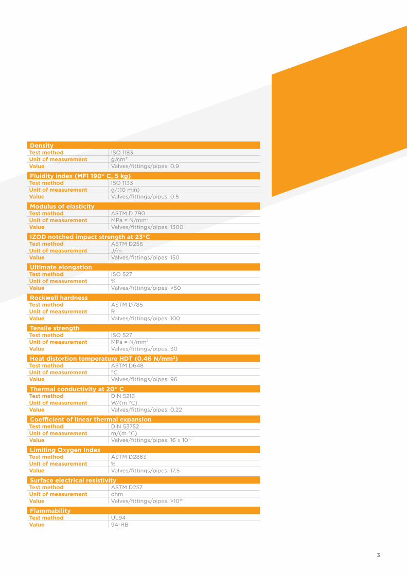
DensityTest method ISO 1183Unit of measurement g/cm3
Value Valves/fittings/pipes: 0.9
Fluidity index (MFI 190° C, 5 kg)Test method ISO 1133Unit of measurement g/(10 min)Value Valves/fittings/pipes: 0.5
Modulus of elasticityTest method ASTM D 790Unit of measurement MPa = N/mm2
Value Valves/fittings/pipes: 1300
IZOD notched impact strength at 23°CTest method ASTM D256Unit of measurement J/mValue Valves/fittings/pipes: 150
Ultimate elongationTest method ISO 527Unit of measurement %Value Valves/fittings/pipes: >50
Rockwell hardnessTest method ASTM D785Unit of measurement RValue Valves/fittings/pipes: 100
Tensile strengthTest method ISO 527Unit of measurement MPa = N/mm2
Value Valves/fittings/pipes: 30
Heat distortion temperature HDT (0.46 N/mm2)Test method ASTM D648Unit of measurement °CValue Valves/fittings/pipes: 96
Thermal conductivity at 20° CTest method DIN 5216Unit of measurement W/(m °C)Value Valves/fittings/pipes: 0.22
Coefficient of linear thermal expansionTest method DIN 53752Unit of measurement m/(m °C)Value Valves/fittings/pipes: 16 x 10-5
Limiting Oxygen IndexTest method ASTM D2863Unit of measurement %Value Valves/fittings/pipes: 17.5
Surface electrical resistivityTest method ASTM D257Unit of measurement ohmValue Valves/fittings/pipes: >1013
FlammabilityTest method UL94
Value 94-HB
3

REFERENCE
• ANSI B16.5 cl.150
Pipe, flanges and stubs - NPS 1/2 to NPS 24 mm / inch.
• ASTM D 4101-06
Polypropylene compound according to the classification PP0110B56000.
• BS 10
Specification for flanges and bolts for pipes, valves and fittings.
• BS 1560
Flanges for pipes, valves and fittings (Class designated). Steel, cast iron and copper alloy flanges. Specification for steel flanges.
• BS 4504
Flanges for pipes, valves and fittings (PN designated).
• DIN 2501
Flanges, dimensions.
• DIN 2999
Whitworth thread for threaded pipes and fittings.
• DIN 8077-8078
PP-H pipe dimensions, metric series.
• DIN 16962
PP-H fittings for socket and butt welding, dimensions.
• DIN 16963
Pipe joints and pipe components for pressurised fluids in HDPE.
• DVS 2202-1
Imperfections of PP-H welded joints, characteristics, descriptions and evaluations.
• DVS 2207-11
Socket and butt welding of PP-H components.
• DVS 2208-1
Machinery and equipment for thermocouple welding pipes, pipe parts and panels.
• EN 558-1
Industrial valves - Overall dimensions of metal valves for use in flanged pipe systems - Part 1: PN designated valves
• EN 1092-1
Flanges and their joints - Circular flanges for pipes, fittings, valves and ac-cessories - Part 1: Steel flanges, PN designated.
• EN ISO 15494
Specifications for components (Pipes, Fittings and Valves) in PP-H for industrial applications.
• ISO 228-1
Pipe threads for connections that do not seal in the thread.
• ISO 5211
Part-turn actuator couplings.
• ISO 7005-1
Metal flanges; part 1: steel flanges.
STANDARDS
Production of the PP-H (100) lines is carried out according to the highest quality standards and in full compliance with the environmental restrictions set by the applicable laws in force and in accordance with ISO 14001. All products are made in accordance with the quality guarantee system in compliance with ISO 9001.
4
• JIS B 2220
Steel pipe flanges.
• UNI 11318
Socket welding of PP-H components.
• UNI 11397
Butt welding of PP-H components.
5
APPROVALS AND
• DIBt
FIP PP-H valves have been tested and certified by DIBt (Deutsches Institut für Bautechnik)
• EAC
FIP PP-H valves are EAC certified in accordance with Russian regulations on Safety, Hygiene and Quality
• RINA
FIP PP-H valves have been recongnised as suitable for conveying, treating domestic and air conditioning waters on board ships and other units clas-sified by RINA.
• TA-Luft
FIP PP-H valves have been tested and certified according to “TA-Luft” by MPA Stuttgart in compliance with the Technical Instruction on Air Quality Control TA-Luft/ VDI 2440
• UKR SEPRO
FIP PP-H valves and fittings are certified in accordance with Ukrainian regu-lations on Safety and Quality
• NIZP
FIP PVC-U fittings have been recognised as suitable for conveying drinking water by the NIZP (National Institute of Public Health - Poland)
QUALITY MARKS
TA-Luft
6

MAINPROPERTIES
Properties of PP-H Benefits
Thermal resistance - service range 0 °C -100 °C (see pressure/temperature regression curves)
Low surface roughness - high flow coefficients (extremely smooth internal walls)
- pressure drop constant over time
- low risk of stoppages due to scaling
- reduced transfer of material to the transported fluid
Chemical resistance - suitable for conveying chemicals (excellent results with salts and highly alkaline solutions)
Abrasion resistance - extremely low operating costs due to its long service life
Insulating - non-conductive (immune to galvanic corrosion)
- no condensation problems
- minimum heat loss
Non-toxic - physiologically safe
- environmental compatibility
Easy jointing (hot socket, butt and electrofusion welding, flanging and threading)
- low installation costs
- possible connection with many accessories and appliances
Low specific weight - low transport costs
- ease of handling and installation
7
SOCKET WELDINGINSTRUCTIONS
Fig. 1
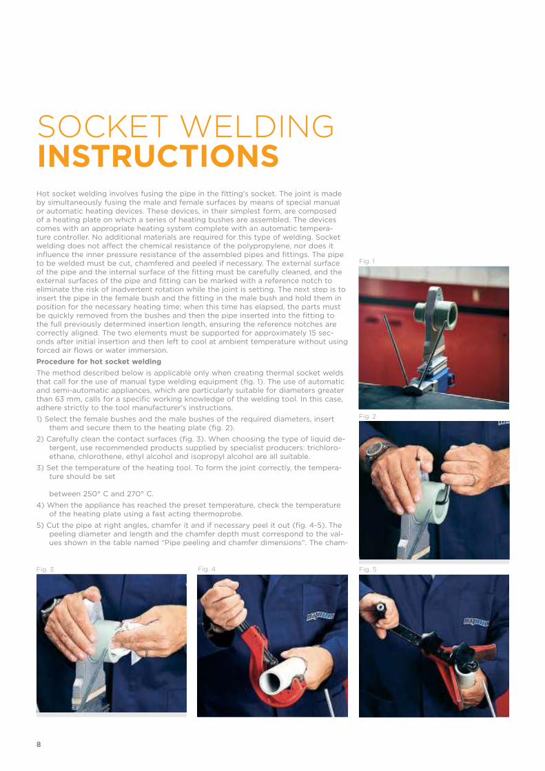
Hot socket welding involves fusing the pipe in the fitting's socket. The joint is made by simultaneously fusing the male and female surfaces by means of special manual or automatic heating devices. These devices, in their simplest form, are composed of a heating plate on which a series of heating bushes are assembled. The devices comes with an appropriate heating system complete with an automatic tempera-ture controller. No additional materials are required for this type of welding. Socket welding does not affect the chemical resistance of the polypropylene, nor does it influence the inner pressure resistance of the assembled pipes and fittings. The pipe to be welded must be cut, chamfered and peeled if necessary. The external surface of the pipe and the internal surface of the fitting must be carefully cleaned, and the external surfaces of the pipe and fitting can be marked with a reference notch to eliminate the risk of inadvertent rotation while the joint is setting. The next step is to insert the pipe in the female bush and the fitting in the male bush and hold them in position for the necessary heating time; when this time has elapsed, the parts must be quickly removed from the bushes and then the pipe inserted into the fitting to the full previously determined insertion length, ensuring the reference notches are correctly aligned. The two elements must be supported for approximately 15 sec-onds after initial insertion and then left to cool at ambient temperature without using forced air flows or water immersion.
Procedure for hot socket welding
The method described below is applicable only when creating thermal socket welds that call for the use of manual type welding equipment (fig. 1). The use of automatic and semi-automatic appliances, which are particularly suitable for diameters greater than 63 mm, calls for a specific working knowledge of the welding tool. In this case, adhere strictly to the tool manufacturer's instructions.
1) Select the female bushes and the male bushes of the required diameters, insert them and secure them to the heating plate (fig. 2).
2) Carefully clean the contact surfaces (fig. 3). When choosing the type of liquid de-tergent, use recommended products supplied by specialist producers: trichloro-ethane, chlorothene, ethyl alcohol and isopropyl alcohol are all suitable.
3) Set the temperature of the heating tool. To form the joint correctly, the tempera-ture should be set between 250° C and 270° C.
4) When the appliance has reached the preset temperature, check the temperature of the heating plate using a fast acting thermoprobe.
5) Cut the pipe at right angles, chamfer it and if necessary peel it out (fig. 4-5). The peeling diameter and length and the chamfer depth must correspond to the val-ues shown in the table named “Pipe peeling and chamfer dimensions”. The cham-
Fig. 2
Fig. 3 Fig. 4 Fig. 5
8
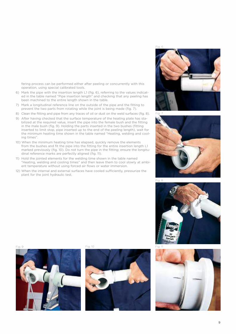
Fig. 6
Fig. 7
Fig. 8
Fig. 9 Fig. 10 Fig. 11
fering process can be performed either after peeling or concurrently with this operation, using special calibrated tools.
6) Mark the pipe with the insertion length L1 (fig. 6), referring to the values indicat-ed in the table named “Pipe insertion length” and checking that any peeling has been machined to the entire length shown in the table.
7) Mark a longitudinal reference line on the outside of the pipe and the fitting to prevent the two parts from rotating while the joint is being made (fig. 7).
8) Clean the fitting and pipe from any traces of oil or dust on the weld surfaces (fig. 8).
9) After having checked that the surface temperature of the heating plate has sta-bilized at the required value, insert the pipe into the female bush and the fitting in the male bush (fig. 9). Holding the parts inserted in the two bushes (fitting inserted to limit stop, pipe inserted up to the end of the peeling length), wait for the minimum heating time shown in the table named “Heating, welding and cool-ing times”.
10) When the minimum heating time has elapsed, quickly remove the elements from the bushes and fit the pipe into the fitting for the entire insertion length L1 marked previously (fig. 10). Do not turn the pipe in the fitting; ensure the longitu-dinal reference marks are perfectly aligned (fig. 11).
11) Hold the jointed elements for the welding time shown in the table named “Heating, welding and cooling times” and then leave them to cool slowly at ambi-ent temperature without using forced air flows or water immersion.
12) When the internal and external surfaces have cooled sufficiently, pressurize the plant for the joint hydraulic test.
9
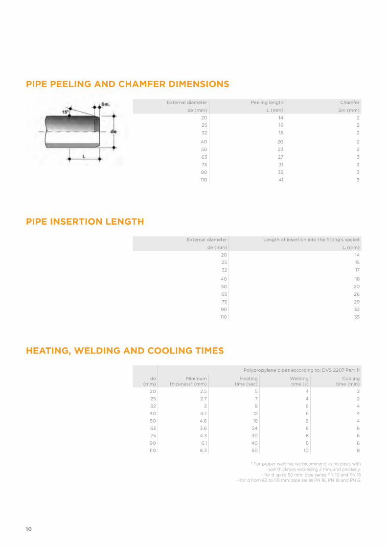
External diameter
de (mm)
Peeling length
L (mm)
Chamfer
Sm (mm)
20 14 2
25 16 2
32 18 2
40 20 2
50 23 2
63 27 3
75 31 3
90 35 3
110 41 3
External diameter
de (mm)
Length of insertion into the fitting's socket
L1 (mm)
20 14
25 15
32 17
40 18
50 20
63 26
75 29
90 32
110 35
PIPE PEELING AND CHAMFER DIMENSIONS
PIPE INSERTION LENGTH
HEATING, WELDING AND COOLING TIMES
de (mm)
Polypropylene pipes according to: DVS 2207 Part 11
Minimum thickness* (mm)
Heating time (sec)
Weldingtime (s)
Coolingtime (min)
20 2.5 5 4 2
25 2.7 7 4 2
32 3 8 6 4
40 3.7 12 6 4
50 4.6 18 6 4
63 3.6 24 8 6
75 4.3 30 8 6
90 6.1 40 8 6
110 6.3 50 10 8
* For proper welding, we recommend using pipes with wall thickness exceeding 2 mm, and precisely:
- for d up to 50 mm: pipe series PN 10 and PN 16 - for d from 63 to 110 mm: pipe series PN 16, PN 10 and PN 6.
10

BUTT WELDINGINSTRUCTIONSButt welding with contact heating elements is the process of jointing two elements (pipes and/or fittings) of the same diameter and thickness, the joining surfaces of which are heated until fusion by contact with a heating element and then, after the heating element has been removed, are pressed together to form the weld.
The following instructions are provided for reference purposes only. Installers must be properly trained and have an in-depth knowledge of the procedures to be fol-lowed according to the type of welding equipment being used.
PRELIMINARY CHECKS BEFORE WELDINGTo ensure the joint is made properly:
• Ambient temperatures must be within the range from +5 °C to +40 °C.
• When inspecting the elements to be welded together, check the dimensions (check for excess ovality)
• Check the working temperature of the heating element with a calibrated contact thermometer. This measurement must be made 10 minutes after the rated tempera-ture has been reached, thus allowing the element to heat up over its entire surface area and depth. Fusion temperature must be between 200° C and 220° C.
• Check the surface of the heating element (integrity of the non-stick coating) and clean with a lint-free cloth or soft paper wipe.
• Check that the welding unit is functioning correctly.
• Check the efficiency of the welding unit jaw clamps; ensure they are able to guar-antee the correct alignment between the two sides of the joint and that the con-tact surfaces are perfectly parallel.
• Check the pulling force of the carriage, both in terms of friction and in relation to the load to be moved (pipes or fittings).
• Check the efficiency of the measuring instruments (pressure gauge and timer).
• Check that the pipes and/or fittings to be welded together are of the same diam-eter and thickness (same SDR).
PREPARING FOR WELDING• Cleaning the surfaces:
Before positioning the parts to be welded, remove all traces of dirt, grease, oil, dust, etc., from the external and internal surfaces of the ends, using a clean, lint-free cloth soaked in a suitable detergent. When choosing the type of liquid detergent, use recommended products supplied by specialist producers: trichloroethane, chlo-rothene, ethyl alcohol and isopropyl alcohol are all suitable.
• Clamping the ends:
The ends of the two parts to be welded must be clamped in such a way that axial misalignment does not exceed 10% of the thickness (fig. 1).
• Planing the edges to be welded:
To guarantee proper parallelism and flatness, and, equally important, to eliminate the film of oxide that forms, the ends of the two parts to be joined must be planed. When this procedure is concluded, bring the two ends into contact and ensure that any clearances between them do not exceed 0.5 mm. The shavings must form continuously on both the edges to be welded (fig. 2). It is good practice, after the planing stage, to inspect the resulting shavings to verify the absence of manufac-turing defects. Shavings must be removed from the internal surface of the com-ponents to be welded using a brush or a clean cloth. In any event, after planing, the two surfaces must not be touched or contaminated in any other way; for this reason the welding operations must be performed immediately after preparation. If
Fig. 1
Fig. 2
11

any traces of dust have settled on the planed surfaces, before they can be welded they should be cleaned with a cloth soaked in specific detergent.
BUTT WELDING PROCEDURE The butt fusion welding of pipes and/or fittings using contact heating elements must be performed by carrying out all the steps in the welding cycle, as described in the "Welding Cycle" table.
• Contact and preheating:
In this step, the two edges to be welded are located against the heating element at a pressure equal to p1+pt, for the necessary time, with the purpose of creating a uniform internal and external lip (fig. 3). The pressure value p1 must be such that, when in contact with the heating element, the surfaces to be welded are subjected to a pressure of 0.1 N/mm2; to achieve this condition, p1 pressure values must be taken from the tables supplied by manufacturer of the fusion jointing machine, be-cause, apart from the diameter and thickness of the elements to be welded, these values also depend on the cross section of the thrust cylinder in the welder circuit and can therefore alter in accordance with the specific model of welding unit you are using.
The symbol pt indicates the pulling pressure required to overcome the friction of-fered by the welding unit and the weight of the pipe locked in the mobile guide, combining to impede the free movement of the guide. This reading is taken on the pressure gauge supplied with the machine, while moving the mobile guide (fig. 4). In any event, it must never be higher than the pressure value p1, otherwise it may prove necessary to use carriages or suspension systems to facilitate movement of the pipe.
• Heating:
After the lip has formed, the pressure is lowered (10% of the contact and preheat-ing value), thus allowing the material to heat up uniformly through its entire depth.
• Removing the heating element:
This phase must be performed as rapidly as possible, detaching the pipe edges to be welded from the heating element, extracting the element without damaging the softened surfaces and then immediately bringing the two edges to be welded into contact with each other. This procedure must be performed quickly to avoid the risk of excessive cooling of the edges (surface temperature falls by 17 °C in just 3 seconds)
• Jointing build-up period:
The two edges are brought into contact and the relative pressure is increased pro-gressively to the value (p5+pt), where p5=p1 and pt is the pulling pressure (fig. 5).
• Welding:
Welding pressure must be maintained for time t5 (fig. 6).
• Cooling:
Once the joint has been welded, contact pressure is removed and the joined parts can be removed from the fusion jointing machine, although it must not be sub-jected to mechanical stress until it has cooled completely. Cooling time must be at least the same as welding time t5.
Fig. 6
Fig. 3
Fig. 4
Fig. 5
12

Minimumpipe
(mm)
Contactbead height
(mm)
Preheating time
(sec)
Heating element removal time max.
(sec)
Jointing build-up period
(sec)
Welding time
(min)
... - 4.5 0.5 ... - 135 5 6 6
4.5 - 7 0.5 135 - 175 5 - 6 6 - 7 6 - 12
7 - 12 1 175 - 245 6 - 7 7 - 11 12 - 20
12 - 19 1 245 - 330 7 - 9 11 - 17 20 - 30
19 - 26 1.5 330 - 400 9 - 11 17 - 22 30 - 40
26 - 37 2 400 - 485 11 - 14 22 - 32 40 - 55
37 - 50 2.5 485 - 560 14 - 17 32 - 43 55 - 70
PRESSURE
TIME
Contact andpreheating
Heating Removing the heating element
Jointing build-up period
Welding Coolingp=0.10 N/mm2
WELDING CYCLE
13
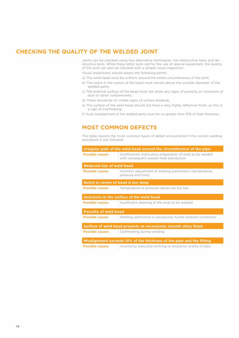
MOST COMMON DEFECTS
Irregular path of the weld bead around the circumference of the pipe
Possible causes Insufficiently meticulous preparation of ends to be welded with consequent uneven heat distribution
Reduced size of weld bead
Possible causes Incorrect adjustment of welding parameters (temperature, pressure and time)
Notch in centre of bead is too deep
Possible causes Temperature or pressure values are too low
Inclusions in the surface of the weld bead
Possible causes Insufficient cleaning of the ends to be welded
Porosity of weld bead
Possible causes Welding performed in excessively humid ambient conditions
Surface of weld bead presents an excessively smooth shiny finish
Possible causes Overheating during welding
Misalignment exceeds 10% of the thickness of the pipe and the fitting
Possible causes Incorrectly executed centring or excessive ovality of pipe
The table reports the most common types of defect encountered if the correct welding procedure is not followed.
Joints can be checked using two alternative techniques: non-destructive tests and de-structive tests. While these latter tests call for the use of special equipment, the quality of the joint can also be checked with a simple visual inspection.
Visual inspections should assess the following points:
a) The weld bead must be uniform around the entire circumference of the joint;
b) The notch in the centre of the bead must remain above the outside diameter of the welded parts;
c) The external surface of the bead must not show any signs of porosity or inclusions of dust or other contaminants;
d) There should be no visible signs of surface breakup;
e) The surface of the weld bead should not have a very highly reflective finish, as this is a sign of overheating;
f) Axial misalignment of the welded parts must be no greater than 10% of their thickness.
CHECKING THE QUALITY OF THE WELDED JOINT
14
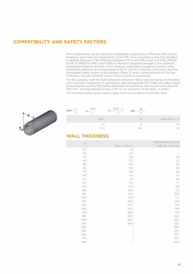
dSDR = __
s
(SDR - 1) S = ________
2
σPN = ______
S
MRSσ = ____
c
dWall thickness S (mm)
SDR 11 - ISO S 5 SDR 17.6 - ISO S 8.3
20 1.9 -
25 2.3 -
32 2.9 1.8
40 3.7 2.3
50 4.6 2.9
63 5.8 3.6
75 6.8 4.3
90 8.2 5.1
110 10 6.3
125 11.4 7.1
140 12.7 8.0
160 14.6 9.1
180 16.4 10.2
200 18.2 11.4
225 20.5 12.8
250 22.7 14.2
280 25.4 15.9
315 28.6 17.9
355 32.2 20.1
400 36.3 22.7
450 40.9 25.5
500 - 28.4
560 - 31.7
630 - 35.7
710 - 40.2
800 - 45.3
SDR S Safety factor = C
11 5 1.6
17.6 8.3 1.6
PP-H components can be welded to compatible components in PPR and PPB without problems, once that the compatibility of the MFI value according to the DVS standard is verified. Because of the difference between PP-H and PPR in terms of MRS (MRS10 for PP-H, MRS8 for PPR, where MRS or Minimum Required Strength is the minimum guaranteed breaking strength of the material, subjected to tangential tension using hydrostatic pressure, at a temperature of 20 °C and for a lifetime of 50 years) and the consequent safety factors to be adopted (Table 1), exact correspondence of the wall thickness / outside diameter ratio is of the maximum importance.
For this purpose, both the SDR (Standard Dimension Ratio) and the Series of thickness-es S have been introduced. In accordance with standard EN ISO 15494, the safety factor to be adopted and the SDR/Series determine the reference nominal pressure value PN (PN: max. working pressure in bar at 20 °C, for a duration of 50 years, in water).
The minimum safety factor value is taken from the standard UNI EN ISO 12162.
WALL THICKNESS
COMPATIBILITY AND SAFETY FACTORS
15

INSTALLATION INSTRUCTIONS FOR THREADED JOINTS
Fig. 1
To guarantee the hydraulic seal of the joint on fittings and valves with a threaded female end, we recommend you perform the following operations:
1. Start winding some PTFE sealing tape on the outside of the threaded male end, taking care not to obstruct the through-hole on the pipe, fitting or valve (fig. 1);
2. Complete the first winding layer by winding the tape clockwise until you reach the root of the thread. Remember to keep the tape taut throughout the entire process (fig. 2);
3. Press on the tips of the thread to make sure the tape adheres fully to the support clip;
4. Increase the thickness of the PTFE layer by continuing to apply the taut tape and winding it clockwise until you achieve the optimal level (fig. 3);
5. Connect the previously sealed male end to the female end and proceed manually by screwing the two elements;
6. Make sure the layer of PTFE is not removed during screwing, as this would compromise the hydraulic seal of the joint;
7. Complete screwing the two ends exploiting the entire length of the thread with the aid of a strap wrench or similar tool;
8. Avoid tightening the elements too much, as this could damage the threads or cause stress to the elements themselves.
Fig. 2
Fig. 3
Avoid using threaded joints in the following cases:
• highly critical applications, such as for conveying chemically aggressive or toxic fluids;
• in the presence of medium or high pressures. In this case, we recommend the use of solvent welding joints, hot welding joints or flanged joints;
• systems subject to mechanical and/or thermal stresses such as water hammers, strong variations in temperature, bends, misalignments and cross tensions which could cause the threaded joint to break prematurely;
• coupling of elements with excessive distance from one another.
WARNINGS
RECOMMENDATIONSFor correct installation, we recommend you only use sealing tape in non-sintered PTFE. Under all circumstances avoid using materials such as hemp, lint or paints usually implemented for the hydraulic seal on metal threads.
16
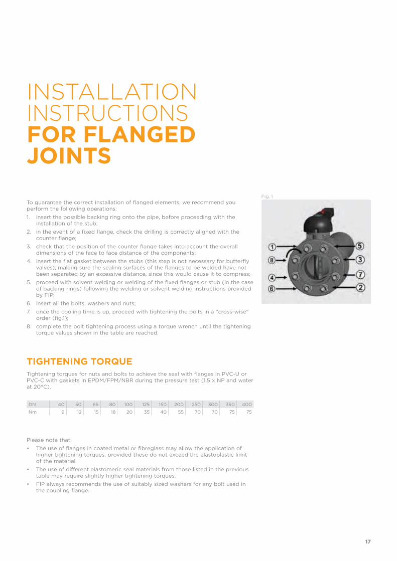
INSTALLATION INSTRUCTIONS FOR FLANGED JOINTS
To guarantee the correct installation of flanged elements, we recommend you perform the following operations:
1. insert the possible backing ring onto the pipe, before proceeding with the installation of the stub;
2. in the event of a fixed flange, check the drilling is correctly aligned with the counter flange;
3. check that the position of the counter flange takes into account the overall dimensions of the face to face distance of the components;
4. insert the flat gasket between the stubs (this step is not necessary for butterfly valves), making sure the sealing surfaces of the flanges to be welded have not been separated by an excessive distance, since this would cause it to compress;
5. proceed with solvent welding or welding of the fixed flanges or stub (in the case of backing rings) following the welding or solvent welding instructions provided by FIP;
6. insert all the bolts, washers and nuts;
7. once the cooling time is up, proceed with tightening the bolts in a "cross-wise" order (fig.1);
8. complete the bolt tightening process using a torque wrench until the tightening torque values shown in the table are reached.
Fig. 1
Please note that:
• The use of flanges in coated metal or fibreglass may allow the application of higher tightening torques, provided these do not exceed the elastoplastic limit of the material.
• The use of different elastomeric seal materials from those listed in the previous table may require slightly higher tightening torques.
• FIP always recommends the use of suitably sized washers for any bolt used in the coupling flange.
TIGHTENING TORQUE Tightening torques for nuts and bolts to achieve the seal with flanges in PVC-U or PVC-C with gaskets in EPDM/FPM/NBR during the pressure test (1.5 x NP and water at 20°C),
DN 40 50 65 80 100 125 150 200 250 300 350 400
Nm 9 12 15 18 20 35 40 55 70 70 75 75
17
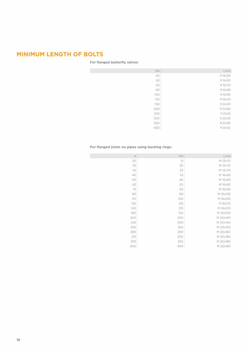
MINIMUM LENGTH OF BOLTSFor flanged butterfly valves:
For flanged joints on pipes using backing rings:
DN Lmin
40 M 16x150
50 M 16x150
65 M 16x170
80 M 16x180
100 M 16x180
125 M 16x210
150 M 20x240
200 M 20x260
250 M 20x310
300 M 20x340
350 M 20x360
400 M 24x420
d DN Lmin
20 15 M 12x70
25 20 M 12x70
32 25 M 12x70
40 32 M 16x85
50 40 M 16x85
63 50 M 16x95
75 65 M 16x95
90 80 M 16x105
110 100 M 16x105
125 125 M 16x115
140 125 M 16x120
160 150 M 20x135
200 200 M 20x140
225 200 M 20x140
250 250 M 20x150
280 250 M 20x160
315 300 M 20x180
355 350 M 20x180
400 400 M 22x180
18

19

ISO-UNI PIPE
PP-H
Pressure pipe

ISO-UNIPIPE
PRESSURE PIPEPressure pipes for connection system by butt or socket welding.
Technical specifications
Size range d 20 ÷ d 400 (mm)
Nominal pressure SDR 17,6 (PN6) with water at 20 °CSDR 11 (PN10) with water at 20 °C
Temperature range 0 °C ÷ 100 °C
Coupling standards Welding: EN ISO 15494 Can be coupled to pipes according to EN ISO 15494
Reference standards Construction criteria: EN ISO 15494
Test methods and requirements: EN ISO 15494
Installation criteria: DVS 2202-1, DVS 2207-11, DVS 2208-1, UNI 11318, UNI 11397
Material PP-H
22
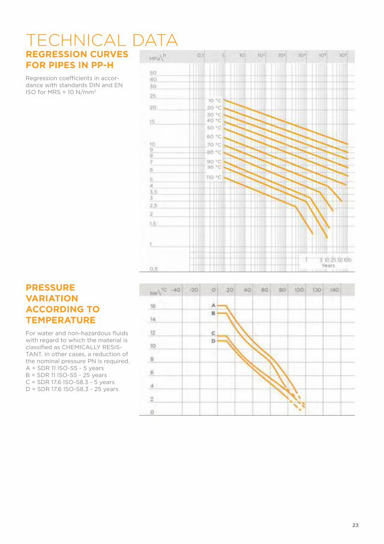
REGRESSION CURVES FOR PIPES IN PP-H
Regression coefficients in accor-dance with standards DIN and EN ISO for MRS = 10 N/mm2
PRESSURE VARIATION ACCORDING TO TEMPERATURE
For water and non-hazardous fluids with regard to which the material is classified as CHEMICALLY RESIS-TANT. In other cases, a reduction of the nominal pressure PN is required.A = SDR 11 ISO-S5 - 5 yearsB = SDR 11 ISO-S5 - 25 yearsC = SDR 17.6 ISO-S8.3 - 5 yearsD = SDR 17.6 ISO-S8.3 - 25 years
23
TECHNICAL DATA
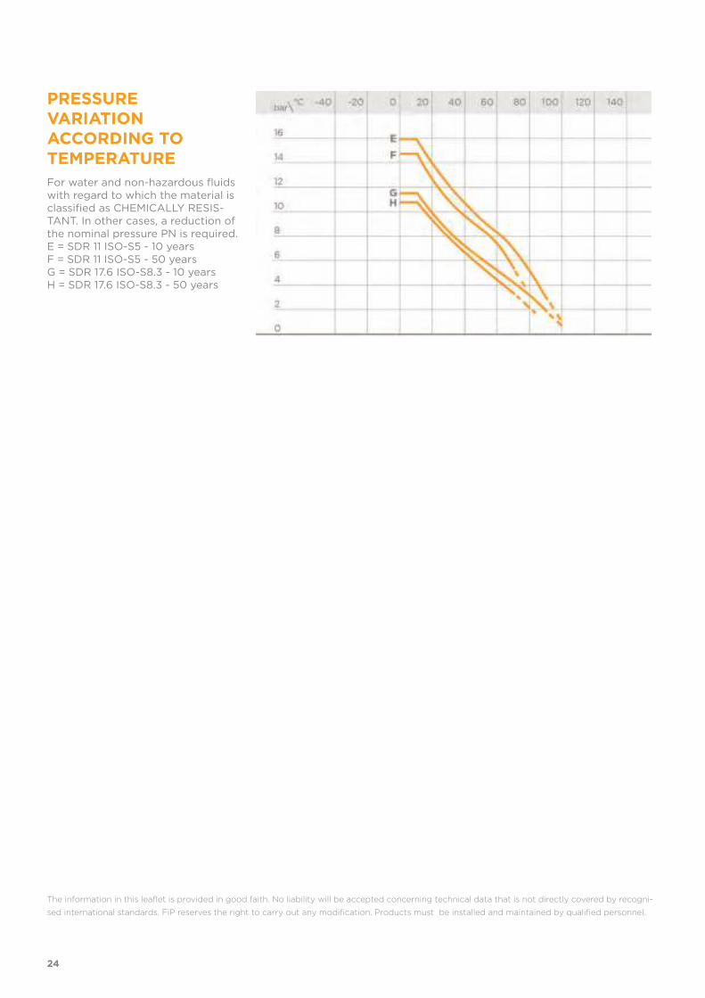
PRESSURE VARIATION ACCORDING TO TEMPERATURE
For water and non-hazardous fluids with regard to which the material is classified as CHEMICALLY RESIS-TANT. In other cases, a reduction of the nominal pressure PN is required.E = SDR 11 ISO-S5 - 10 yearsF = SDR 11 ISO-S5 - 50 yearsG = SDR 17.6 ISO-S8.3 - 10 yearsH = SDR 17.6 ISO-S8.3 - 50 years
The information in this leaflet is provided in good faith. No liability will be accepted concerning technical data that is not directly covered by recogni-
sed international standards. FiP reserves the right to carry out any modification. Products must be installed and maintained by qualified personnel.
24
25
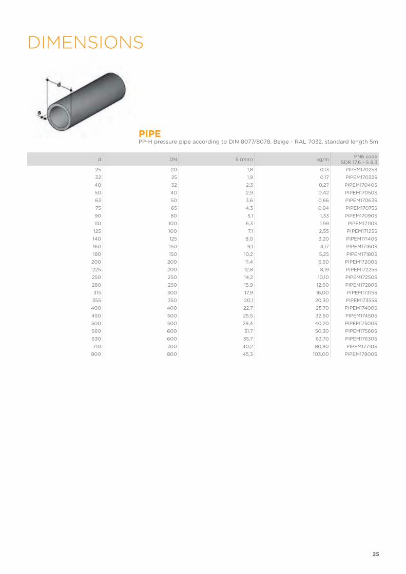
DIMENSIONS
PIPEPP-H pressure pipe according to DIN 8077/8078, Beige - RAL 7032, standard length 5m
d DN S (mm) kg/mPN6 code
SDR 17,6 - S 8,3
25 20 1,8 0,13 PIPEM17025S
32 25 1,9 0,17 PIPEM17032S
40 32 2,3 0,27 PIPEM17040S
50 40 2,9 0,42 PIPEM17050S
63 50 3,6 0,66 PIPEM17063S
75 65 4,3 0,94 PIPEM17075S
90 80 5,1 1,33 PIPEM17090S
110 100 6,3 1,99 PIPEM17110S
125 100 7,1 2,55 PIPEM17125S
140 125 8,0 3,20 PIPEM17140S
160 150 9,1 4,17 PIPEM17160S
180 150 10,2 5,25 PIPEM17180S
200 200 11,4 6,50 PIPEM17200S
225 200 12,8 8,19 PIPEM17225S
250 250 14,2 10,10 PIPEM17250S
280 250 15,9 12,60 PIPEM17280S
315 300 17,9 16,00 PIPEM17315S
355 350 20,1 20,30 PIPEM17355S
400 400 22,7 25,70 PIPEM17400S
450 500 25,5 32,50 PIPEM17450S
500 500 28,4 40,20 PIPEM17500S
560 600 31,7 50,30 PIPEM17560S
630 600 35,7 63,70 PIPEM17630S
710 700 40,2 80,80 PIPEM17710S
800 800 45,3 103,00 PIPEM17800S
26
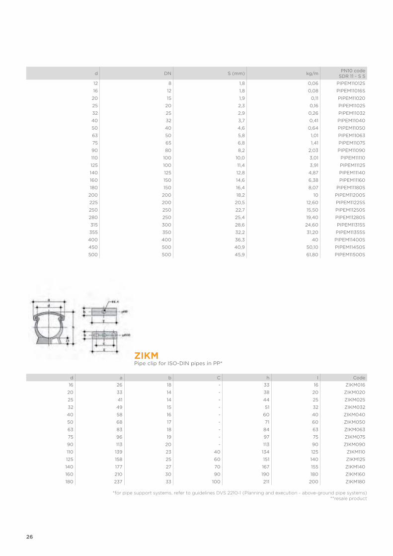
d DN S (mm) kg/mPN10 code
SDR 11 - S 5
12 8 1,8 0,06 PIPEM11012S
16 12 1,8 0,08 PIPEM11016S
20 15 1,9 0,11 PIPEM11020
25 20 2,3 0,16 PIPEM11025
32 25 2,9 0,26 PIPEM11032
40 32 3,7 0,41 PIPEM11040
50 40 4,6 0,64 PIPEM11050
63 50 5,8 1,01 PIPEM11063
75 65 6,8 1,41 PIPEM11075
90 80 8,2 2,03 PIPEM11090
110 100 10,0 3,01 PIPEM11110
125 100 11,4 3,91 PIPEM11125
140 125 12,8 4,87 PIPEM11140
160 150 14,6 6,38 PIPEM11160
180 150 16,4 8,07 PIPEM11180S
200 200 18,2 10 PIPEM11200S
225 200 20,5 12,60 PIPEM11225S
250 250 22,7 15,50 PIPEM11250S
280 250 25,4 19,40 PIPEM11280S
315 300 28,6 24,60 PIPEM11315S
355 350 32,2 31,20 PIPEM11355S
400 400 36,3 40 PIPEM11400S
450 500 40,9 50,10 PIPEM11450S
500 500 45,9 61,80 PIPEM11500S
ZIKMPipe clip for ISO-DIN pipes in PP*
d a b C h I Code
16 26 18 - 33 16 ZIKM016
20 33 14 - 38 20 ZIKM020
25 41 14 - 44 25 ZIKM025
32 49 15 - 51 32 ZIKM032
40 58 16 - 60 40 ZIKM040
50 68 17 - 71 60 ZIKM050
63 83 18 - 84 63 ZIKM063
75 96 19 - 97 75 ZIKM075
90 113 20 - 113 90 ZIKM090
110 139 23 40 134 125 ZIKM110
125 158 25 60 151 140 ZIKM125
140 177 27 70 167 155 ZIKM140
160 210 30 90 190 180 ZIKM160
180 237 33 100 211 200 ZIKM180
*for pipe support systems, refer to guidelines DVS 2210-1 (Planning and execution - above-ground pipe systems)**resale product
27
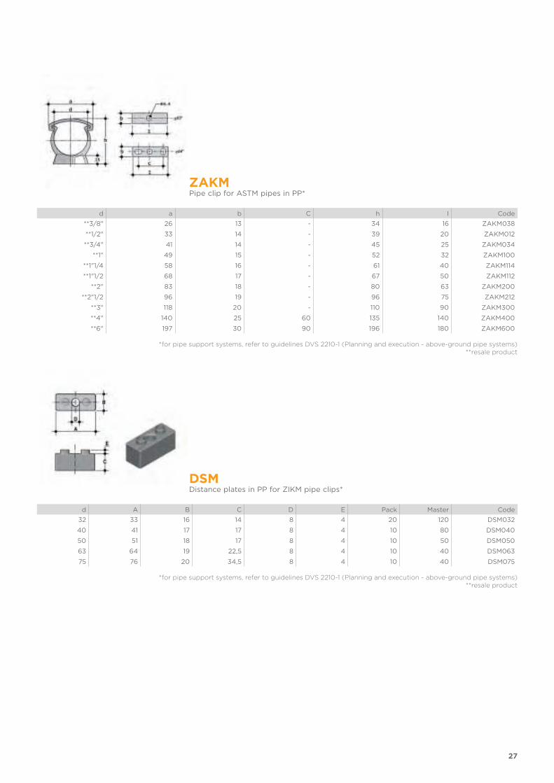
ZAKMPipe clip for ASTM pipes in PP*
d a b C h I Code
**3/8" 26 13 - 34 16 ZAKM038
**1/2" 33 14 - 39 20 ZAKM012
**3/4" 41 14 - 45 25 ZAKM034
**1" 49 15 - 52 32 ZAKM100
**1"1/4 58 16 - 61 40 ZAKM114
**1"1/2 68 17 - 67 50 ZAKM112
**2" 83 18 - 80 63 ZAKM200
**2"1/2 96 19 - 96 75 ZAKM212
**3" 118 20 - 110 90 ZAKM300
**4" 140 25 60 135 140 ZAKM400
**6" 197 30 90 196 180 ZAKM600
*for pipe support systems, refer to guidelines DVS 2210-1 (Planning and execution - above-ground pipe systems)**resale product
DSMDistance plates in PP for ZIKM pipe clips*
d A B C D E Pack Master Code
32 33 16 14 8 4 20 120 DSM032
40 41 17 17 8 4 10 80 DSM040
50 51 18 17 8 4 10 50 DSM050
63 64 19 22,5 8 4 10 40 DSM063
75 76 20 34,5 8 4 10 40 DSM075
*for pipe support systems, refer to guidelines DVS 2210-1 (Planning and execution - above-ground pipe systems)**resale product
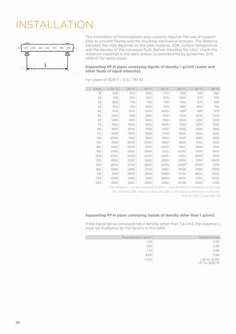
The installation of thermoplastic pipe systems requires the use of support clips to prevent flexing and the resulting mechanical stresses. The distance between the clips depends on the pipe material, SDR, surface temperature and the density of the conveyed fluid. Before installing the clips, check the distances reported in the table below, as provided for by guidelines DVS 2210-01 for water pipes.
Supporting PP-H pipes conveying liquids of density 1 g/cm3 (water and other fluids of equal intensity)
For pipes of SDR 11 / S 5 / PN 10:
d mm < 20 °C 30 °C 40 °C 50 °C 60 °C 70 °C 80 °C
16 650 625 600 575 550 525 500
20 700 675 650 625 600 575 550
25 800 775 750 725 700 675 650
32 950 925 900 875 850 800 750
40 1100 1075 1050 1000 950 925 875
50 1250 1225 1200 1150 1100 1050 1000
63 1450 1425 1400 1350 1300 1250 1200
75 1550 1500 1500 1400 1350 1300 1250
90 1650 1600 1700 1500 1450 1400 1350
110 1850 1800 1800 1700 1600 1500 1400
125 2000 1950 1900 1800 1700 1600 1500
140 2100 2050 2000 1900 1800 1700 1600
160 2250 2200 2100 2000 1900 1800 1700
180 2350 2300 2200 2100 2000 1900 1800
200 2500 2400 2300 2200 2100 2000 1900
225 2650 2550 2450 2350 2250 2150 2000
250 2800 2700 2600 2500 2400 2300 2150
280 2950 2850 2750 2650 2550 2450 2300
315 3150 3050 2950 2850 2700 2600 2450
355 3350 3250 3150 3000 2850 2750 2600
400 3550 3450 3350 3200 3050 2900 2750
* The distance L can be increased by 30% in case of vertical installation of the pipe
For different SDR values, multiply the data in the table by the following factors:
0.91 for SDR 17 and SDR 17.6
Supporting PP-H pipes conveying liquids of density other than 1 g/cm3.
If the liquid being conveyed has a density other than 1 g/cm3, the distance L must be multiplied by the factors in the table
Fluid density in g/cm3 Support factor
1,25 0,96
1,50 0,92
1,75 0,88
2,00 0,94
< 0,01 1.30 for SDR111.47 for SDR17.6
28
INSTALLATION


FITTINGS
FOR SOCKET WELDING
PP-H
Fittings, metric series ISO-UNI
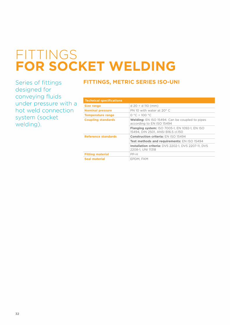
FITTINGSFOR SOCKET WELDING
FITTINGS, METRIC SERIES ISO-UNISeries of fittings designed for conveying fluids under pressure with a hot weld connection system (socket welding).
Technical specifications
Size range d 20 ÷ d 110 (mm)
Nominal pressure PN 10 with water at 20° C
Temperature range 0 °C ÷ 100 °C
Coupling standards Welding: EN ISO 15494. Can be coupled to pipes according to EN ISO 15494
Flanging system: ISO 7005-1, EN 1092-1, EN ISO 15494, DIN 2501, ANSI B16.5 cl.150
Reference standards Construction criteria: EN ISO 15494
Test methods and requirements: EN ISO 15494
Installation criteria: DVS 2202-1, DVS 2207-11, DVS 2208-1, UNI 11318
Fitting material PP-H
Seal material EPDM, FKM
32
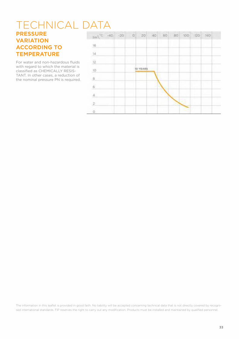
PRESSURE VARIATION ACCORDING TO TEMPERATURE
For water and non-hazardous fluids with regard to which the material is classified as CHEMICALLY RESIS-TANT. In other cases, a reduction of the nominal pressure PN is required.
The information in this leaflet is provided in good faith. No liability will be accepted concerning technical data that is not directly covered by recogni-
sed international standards. FIP reserves the right to carry out any modification. Products must be installed and maintained by qualified personnel.
33
TECHNICAL DATA
34
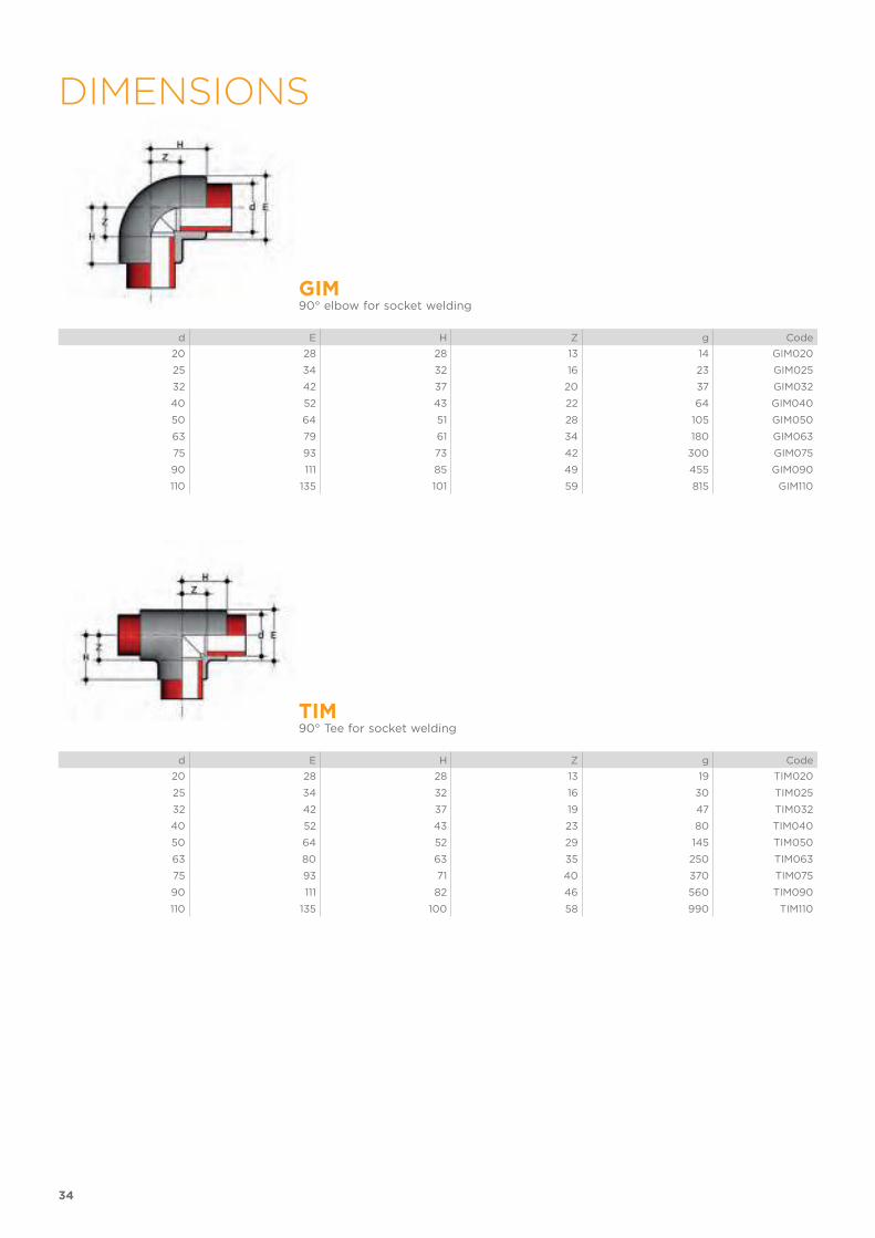
DIMENSIONS
GIM90° elbow for socket welding
d E H Z g Code
20 28 28 13 14 GIM020
25 34 32 16 23 GIM025
32 42 37 20 37 GIM032
40 52 43 22 64 GIM040
50 64 51 28 105 GIM050
63 79 61 34 180 GIM063
75 93 73 42 300 GIM075
90 111 85 49 455 GIM090
110 135 101 59 815 GIM110
TIM90° Tee for socket welding
d E H Z g Code
20 28 28 13 19 TIM020
25 34 32 16 30 TIM025
32 42 37 19 47 TIM032
40 52 43 23 80 TIM040
50 64 52 29 145 TIM050
63 80 63 35 250 TIM063
75 93 71 40 370 TIM075
90 111 82 46 560 TIM090
110 135 100 58 990 TIM110
35
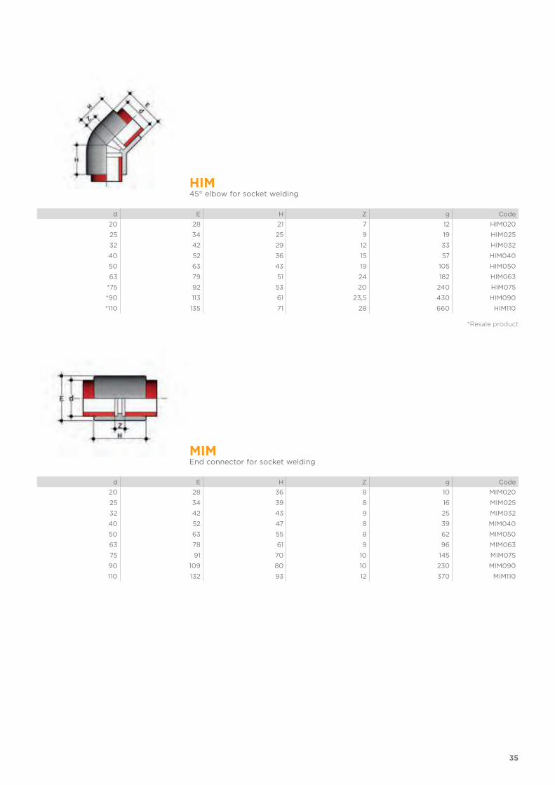
HIM45° elbow for socket welding
d E H Z g Code
20 28 21 7 12 HIM020
25 34 25 9 19 HIM025
32 42 29 12 33 HIM032
40 52 36 15 57 HIM040
50 63 43 19 105 HIM050
63 79 51 24 182 HIM063
*75 92 53 20 240 HIM075
*90 113 61 23,5 430 HIM090
*110 135 71 28 660 HIM110
*Resale product
MIMEnd connector for socket welding
d E H Z g Code
20 28 36 8 10 MIM020
25 34 39 8 16 MIM025
32 42 43 9 25 MIM032
40 52 47 8 39 MIM040
50 63 55 8 62 MIM050
63 78 61 9 96 MIM063
75 91 70 10 145 MIM075
90 109 80 10 230 MIM090
110 132 93 12 370 MIM110
36
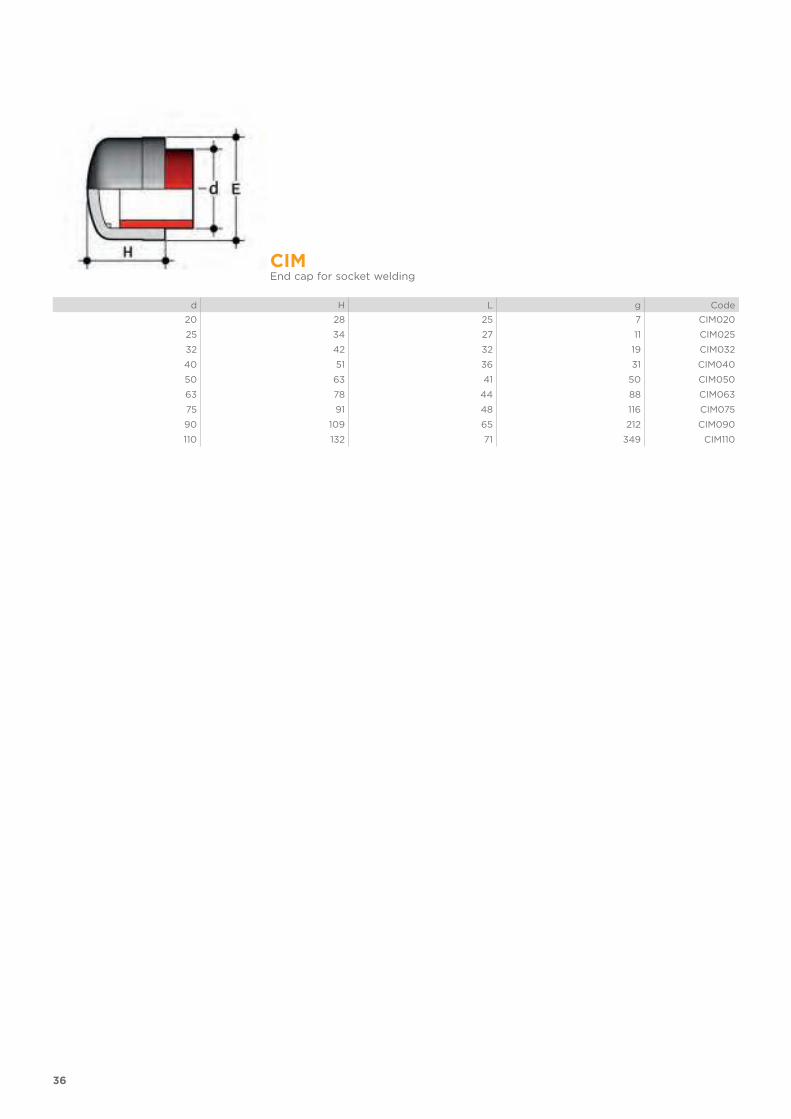
CIMEnd cap for socket welding
d H L g Code
20 28 25 7 CIM020
25 34 27 11 CIM025
32 42 32 19 CIM032
40 51 36 31 CIM040
50 63 41 50 CIM050
63 78 44 88 CIM063
75 91 48 116 CIM075
90 109 65 212 CIM090
110 132 71 349 CIM110

37
BIGMUnion for socket welding with O-Ring in EPDM or FKM
d R1
PN E H Z1
Z2 gEPDM code
FKM code
20 1" 10 47 45,5 12 5,5 34 BIGM020E BIGM020F
25 1"1/4 10 58 49,5 12 5,5 59 BIGM025E BIGM025F
32 1"1/2 10 65 53,5 12 5,5 73 BIGM032E BIGM032F
40 2" 10 78 59,5 14 5,5 115 BIGM040E BIGM040F
50 2"1/4 10 85 67,5 16 5,5 146 BIGM050E BIGM050F
63 2"3/4 10 103 79,5 20 5,5 249 BIGM063E BIGM063F
EFGMUnion nut with BSP thread for union types BIGM, BIFGM, BIFOM, BIROM, BIFXM, BIRXM
R d BIGM PN E F H g Code
1" 20 10 47 28 22 19 EFGM100
1"1/4 25 10 58 36 25 29 EFGM114
1"1/2 32 10 65 42 27 40 EFGM112
2" 40 10 78 53 30 57 EFGM200
2"1/4 50 10 85 59 33 74 EFGM214
2"3/4 63 10 103 74 38 119 EFGM234
38
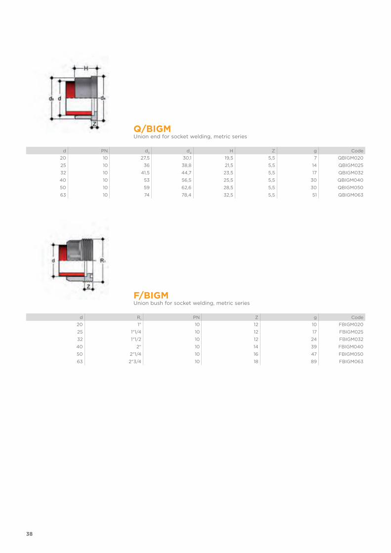
Q/BIGMUnion end for socket welding, metric series
d PN d3
d4
H Z g Code
20 10 27,5 30,1 19,5 5,5 7 QBIGM020
25 10 36 38,8 21,5 5,5 14 QBIGM025
32 10 41,5 44,7 23,5 5,5 17 QBIGM032
40 10 53 56,5 25,5 5,5 30 QBIGM040
50 10 59 62,6 28,5 5,5 30 QBIGM050
63 10 74 78,4 32,5 5,5 51 QBIGM063
F/BIGMUnion bush for socket welding, metric series
d R1
PN Z g Code
20 1" 10 12 10 FBIGM020
25 1"1/4 10 12 17 FBIGM025
32 1"1/2 10 12 24 FBIGM032
40 2" 10 14 39 FBIGM040
50 2"1/4 10 16 47 FBIGM050
63 2"3/4 10 18 89 FBIGM063

39
O-RINGSeals for union types BIGM, BIFGM, BIFOM, BIROM, BIFXM, BIRXM
d union C di T EPDM Code FKM Code
16 3062 15,54 2,62 OR3062E OR3062F
20 4081 20,22 3,53 OR4081E OR4081F
25 4112 28,17 3,53 OR4112E OR4112F
32 4131 32,93 3,53 OR4131E OR4131F
40 6162 40,65 5,34 OR6162E OR6162F
50 6187 47 5,34 OR6187E OR6187F
63 6237 59,69 5,34 OR6237E OR6237F
75 6300 75,57 5,34 OR6300E OR6300F
90 6362 91,45 5,34 OR6362E OR6362F
110 6450 113,67 5,34 OR6450E OR6450F

40
RIMReducer: spigot (d), reduced socket for socket welding (d1)
d x d1
E H Z g Code
25 x 20 28 39 25 10 RIM025020
32 x 20 36 43 30 13 RIM032020
32 x 25 34 46 30 17 RIM032025
40 x 25 42 48 33 24 RIM040025
40 x 32 42 51 33 27 RIM040032
50 x 32 52 54 36 39 RIM050032
50 x 40 52 57 36 44 RIM050040
63 x 32 65 61 44 69 RIM063032
63 x 50 65 68 44 76 RIM063050
75 x 50 78 69 47 106 RIM075050
75 x 63 78 75 47 115 RIM075063
90 x 63 92 82 56 156 RIM090063
90 x 75 92 88 56 175 RIM090075
110 x 63 112 93 66 290 RIM110063
110 x 90 112 102 66 305 RIM110090

41
QRNMStub with serrated face (according to DIN standards) for socket welding, for use with backing rings ODB
d DN b d3
d4
H Z g Code
20 15 7 27 45 20 6 12 QRNM020
25 20 9 33 58 22 6 24 QRNM025
32 25 10 41 68 25 6 36 QRNM032
40 32 11 50 78 27 6 47 QRNM040
50 40 12 61 88 30 6 63 QRNM050
63 50 14 76 102 34 6 94 QRNM063
75 65 16 90 122 38 6 149 QRNM075
90 80 17 108 138 44 8 213 QRNM090
110 110 18 131 158 50 8 297 QRNM110
QRAMStub with serrated face for socket welding, for used with backing rings OAB (for other dimensions use QRNM)
d DN OAB size b d3
d5
H Z g Code
25 20 3/4" 9 33 54 22 6 24 QRAM034
32 25 1" 10 41 63 25 6 36 QRAM100
40 32 1"1/4 11 50 72 27 6 47 QRAM114
50 40 1"1/2 12 61 82 30 6 63 QRAM112
90 80 3" 17 108 132 44 8 213 QRAM300
42
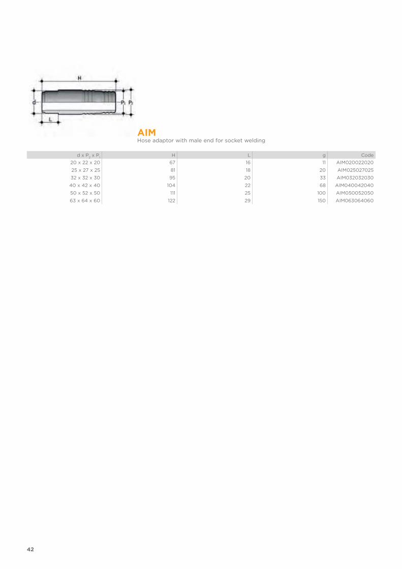
AIMHose adaptor with male end for socket welding
d x P2 x P
1H L g Code
20 x 22 x 20 67 16 11 AIM020022020
25 x 27 x 25 81 18 20 AIM025027025
32 x 32 x 30 95 20 33 AIM032032030
40 x 42 x 40 104 22 68 AIM040042040
50 x 52 x 50 111 25 100 AIM050052050
63 x 64 x 60 122 29 150 AIM063064060
43
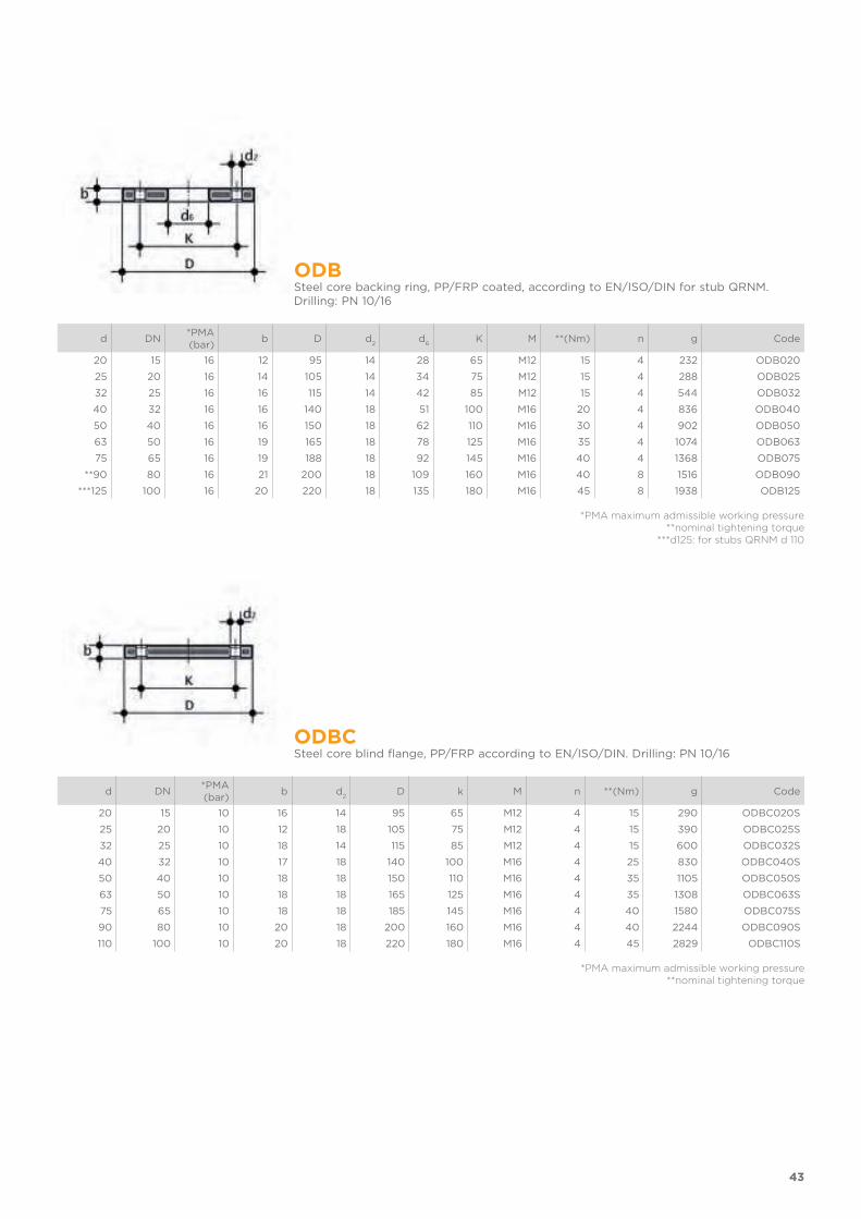
ODBSteel core backing ring, PP/FRP coated, according to EN/ISO/DIN for stub QRNM. Drilling: PN 10/16
d DN*PMA (bar)
b D d2
d6
K M **(Nm) n g Code
20 15 16 12 95 14 28 65 M12 15 4 232 ODB020
25 20 16 14 105 14 34 75 M12 15 4 288 ODB025
32 25 16 16 115 14 42 85 M12 15 4 544 ODB032
40 32 16 16 140 18 51 100 M16 20 4 836 ODB040
50 40 16 16 150 18 62 110 M16 30 4 902 ODB050
63 50 16 19 165 18 78 125 M16 35 4 1074 ODB063
75 65 16 19 188 18 92 145 M16 40 4 1368 ODB075
**90 80 16 21 200 18 109 160 M16 40 8 1516 ODB090
***125 100 16 20 220 18 135 180 M16 45 8 1938 ODB125
*PMA maximum admissible working pressure**nominal tightening torque
***d125: for stubs QRNM d 110
ODBCSteel core blind flange, PP/FRP according to EN/ISO/DIN. Drilling: PN 10/16
d DN*PMA (bar)
b d2
D k M n **(Nm) g Code
20 15 10 16 14 95 65 M12 4 15 290 ODBC020S
25 20 10 12 18 105 75 M12 4 15 390 ODBC025S
32 25 10 18 14 115 85 M12 4 15 600 ODBC032S
40 32 10 17 18 140 100 M16 4 25 830 ODBC040S
50 40 10 18 18 150 110 M16 4 35 1105 ODBC050S
63 50 10 18 18 165 125 M16 4 35 1308 ODBC063S
75 65 10 18 18 185 145 M16 4 40 1580 ODBC075S
90 80 10 20 18 200 160 M16 4 40 2244 ODBC090S
110 100 10 20 18 220 180 M16 4 45 2829 ODBC110S
*PMA maximum admissible working pressure**nominal tightening torque
44
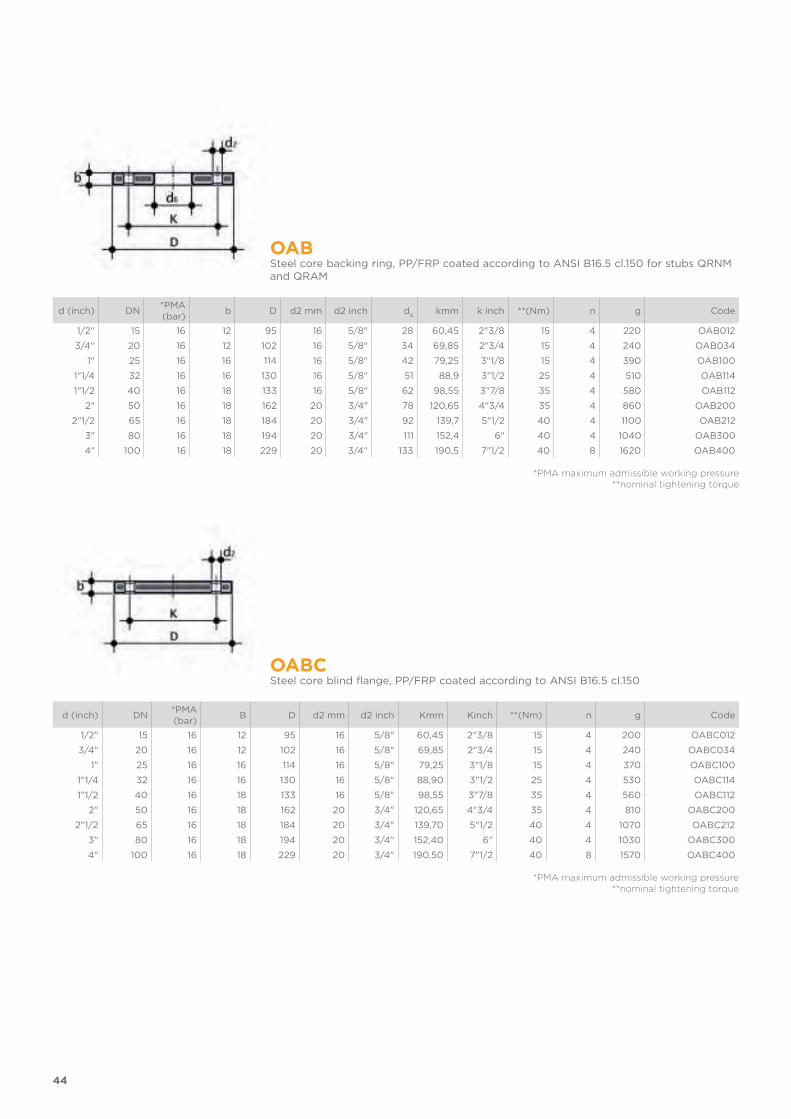
OABSteel core backing ring, PP/FRP coated according to ANSI B16.5 cl.150 for stubs QRNM and QRAM
d (inch) DN*PMA (bar)
b D d2 mm d2 inch d6
kmm k inch **(Nm) n g Code
1/2" 15 16 12 95 16 5/8" 28 60,45 2"3/8 15 4 220 OAB012
3/4" 20 16 12 102 16 5/8" 34 69,85 2"3/4 15 4 240 OAB034
1" 25 16 16 114 16 5/8" 42 79,25 3"1/8 15 4 390 OAB100
1"1/4 32 16 16 130 16 5/8" 51 88,9 3"1/2 25 4 510 OAB114
1"1/2 40 16 18 133 16 5/8" 62 98,55 3"7/8 35 4 580 OAB112
2" 50 16 18 162 20 3/4" 78 120,65 4"3/4 35 4 860 OAB200
2"1/2 65 16 18 184 20 3/4" 92 139,7 5"1/2 40 4 1100 OAB212
3" 80 16 18 194 20 3/4" 111 152,4 6" 40 4 1040 OAB300
4" 100 16 18 229 20 3/4" 133 190,5 7"1/2 40 8 1620 OAB400
*PMA maximum admissible working pressure**nominal tightening torque
OABCSteel core blind flange, PP/FRP coated according to ANSI B16.5 cl.150
d (inch) DN*PMA (bar)
B D d2 mm d2 inch Kmm Kinch **(Nm) n g Code
1/2" 15 16 12 95 16 5/8" 60,45 2"3/8 15 4 200 OABC012
3/4" 20 16 12 102 16 5/8" 69,85 2"3/4 15 4 240 OABC034
1" 25 16 16 114 16 5/8" 79,25 3"1/8 15 4 370 OABC100
1"1/4 32 16 16 130 16 5/8" 88,90 3"1/2 25 4 530 OABC114
1"1/2 40 16 18 133 16 5/8" 98,55 3"7/8 35 4 560 OABC112
2" 50 16 18 162 20 3/4" 120,65 4"3/4 35 4 810 OABC200
2"1/2 65 16 18 184 20 3/4" 139,70 5"1/2 40 4 1070 OABC212
3" 80 16 18 194 20 3/4" 152,40 6" 40 4 1030 OABC300
4" 100 16 18 229 20 3/4" 190,50 7"1/2 40 8 1570 OABC400
*PMA maximum admissible working pressure**nominal tightening torque

45
QHV/X Flat gasket in EPDM and FKM for flanges according to DIN 2501, EN 1092
d DN A B Sp EPDM code FKM code
20 - 1/2" 15 20 32 2 QHVX020E QHVX020F
25 - 3/4" 20 24 38,5 2 QHVX025E QHVX025F
32 - 1" 25 32 48 2 QHVX032E QHVX032F
40 - 1" 1/4 32 40 59 2 QHVX040E QHVX040F
50 - 1"1/2 40 50 71 2 QHVX050E QHVX050F
63 - 2" 50 63 88 2 QHVX063E QHVX063F
75 - 2" 1/2 65 75 104 2 QHVX075E QHVX075F
90 - 3" 80 90 123 2 QHVX090E QHVX090F
110 - 4" 100 110 148 3 QHVX110E QHVX110F
QHV/YFlat gasket in EPDM for flanges according to DIN 2501, EN 1092, self-centring for flanges drilled PN 10/16
d DN A1
B1
F I U Sp Code
20 - 1/2" 15 17 95 14 65 4 2 QHVY020E
25 - 3/4" 20 22 107 14 76,3 4 2 QHVY025E
32 - 1" 25 28 117 14 86,5 4 2 QHVY032E
40 - 1" 1/4 32 36 142,5 18 101 4 2 QHVY040E
50 - 1" 1/2 40 45 153,3 18 111 4 2 QHVY050E
63 - 2" 50 57 168 18 125,5 4 2 QHVY063E
75 - 2" 1/2 65 71 187,5 18 145,5 4 3 QHVY075E
90 - 3" 80 84 203 18 160 8 3 QHVY090E
110 - 4" 100 102 223 18 181 8 3 QHVY110E


FITTINGS
FOR SOCKET WELDING
PP-H
ISO-BSP adaptor fittings
FITTINGS FOR SOCKET WELDING
ISO-BSP ADAPTOR FITTINGSSeries of fittings designed for conveying fluids under pressure with a hot thread and weld connection system (socket welding).
Technical specifications
Size range d 20 ÷ 63 (mm); R 3/8” ÷ 2”
Nominal pressure PN 10 with water at 20° C
Temperature range 0 °C ÷ 100 °C
Coupling standards Welding: EN ISO 15494. Can be coupled to pipes according to EN ISO 15494
Thread: ISO 228-1, DIN 2999
Reference standards Construction criteria: EN ISO 15494
Test methods and requirements: EN ISO 15494
Installation criteria: DVS 2202-1, DVS 2207-11, DVS 2208-1, UNI 11318
Fitting material PP-H
Seal material EPDM, FKM
48

PRESSURE VARIATION ACCORDING TO TEMPERATURE
For water and non-hazardous fluids with regard to which the material is classified as CHEMICALLY RESIS-TANT. In other cases, a reduction of the nominal pressure PN is required.
The information in this leaflet is provided in good faith. No liability will be accepted concerning technical data that is not directly covered by recogni-
sed international standards. FIP reserves the right to carry out any modification. Products must be installed and maintained by qualified personnel.
49
TECHNICAL DATA

50
DIMENSIONS
MIMMEnd connector for socket welding (d) and with female BSP thread (R), with STAINLESS steel reinforcing ring
d x R PN E H Z g Code
20 x 1/2" 10 30 39 8 14 MIMM020012
25 x 3/4" 10 39 41 8 23 MIMM025034
32 x 1" 10 47 45 7 40 MIMM032100
40 x 1"1/4 10 55 50 8 46 MIMM040114
50 x 1"1/2 10 66 55 9 92 MIMM050112
63 x 2" 10 83 63 9 150 MIMM063200
51
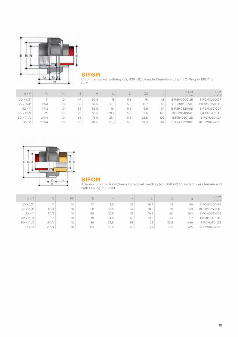
BIFGMUnion for socket welding (d), BSP (R) threaded female end with O-Ring in EPDM or FKM.
d x R R1
PN E H L1
Z1
Z2 gEPDM code
FKM code
20 x 1/2" 1" 10 47 50,5 15 5,5 16 43 BIFGM020012E BIFGM020012F
25 x 3/4" 1"1/4 10 58 54,5 16,3 5,5 16,7 68 BIFGM025034E BIFGM025034F
32 x 1" 1"1/2 10 65 59,5 19,1 5,5 16,9 94 BIFGM032100E BIFGM032100F
40 x 1"1/4 2" 10 78 66,5 21,4 5,5 19,6 145 BIFGM040114E BIFGM040114F
50 x 1"1/2 2"1/4 10 85 73,5 21,4 5,5 23,6 196 BIFGM050112E BIFGM050112F
63 x 2" 2"3/4 10 103 82,5 25,7 5,5 24,3 312 BIFGM063200E BIFGM063200F
BIFOMAdaptor union in PP-H/brass for socket welding (d), BSP (R) threaded brass female end with O-Ring in EPDM
d x R R1
PN E H K L1
Z gEPDM code
20 x 1/2" 1" 10 47 48,5 25 16,5 18 89 BIFOM020012E
25 x 3/4" 1"1/4 10 58 53,5 32 18,5 19 159 BIFOM025034E
32 x 1" 1"1/2 10 65 57,5 38 19,5 20 180 BIFOM032100E
40 x 1"1/4 2" 10 78 64,5 48 21,5 23 357 BIFOM040114E
50 x 1"1/2 2"1/4 10 85 78,5 55 23 32,5 448 BIFOM050112E
63 x 2" 2"3/4 10 103 85,5 69 27 31,5 785 BIFOM063200E
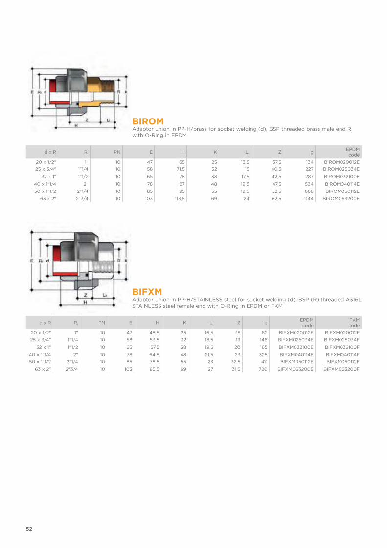
52
BIROMAdaptor union in PP-H/brass for socket welding (d), BSP threaded brass male end R with O-Ring in EPDM
d x R R1
PN E H K L1
Z gEPDM code
20 x 1/2" 1" 10 47 65 25 13,5 37,5 134 BIROM020012E
25 x 3/4" 1"1/4 10 58 71,5 32 15 40,5 227 BIROM025034E
32 x 1" 1"1/2 10 65 78 38 17,5 42,5 287 BIROM032100E
40 x 1"1/4 2" 10 78 87 48 19,5 47,5 534 BIROM040114E
50 x 1"1/2 2"1/4 10 85 95 55 19,5 52,5 668 BIROM050112E
63 x 2" 2"3/4 10 103 113,5 69 24 62,5 1144 BIROM063200E
BIFXMAdaptor union in PP-H/STAINLESS steel for socket welding (d), BSP (R) threaded A316L STAINLESS steel female end with O-Ring in EPDM or FKM
d x R R1
PN E H K L1
Z gEPDM code
FKM code
20 x 1/2" 1" 10 47 48,5 25 16,5 18 82 BIFXM020012E BIFXM020012F
25 x 3/4" 1"1/4 10 58 53,5 32 18,5 19 146 BIFXM025034E BIFXM025034F
32 x 1" 1"1/2 10 65 57,5 38 19,5 20 165 BIFXM032100E BIFXM032100F
40 x 1"1/4 2" 10 78 64,5 48 21,5 23 328 BIFXM040114E BIFXM040114F
50 x 1"1/2 2"1/4 10 85 78,5 55 23 32,5 411 BIFXM050112E BIFXM050112F
63 x 2" 2"3/4 10 103 85,5 69 27 31,5 720 BIFXM063200E BIFXM063200F
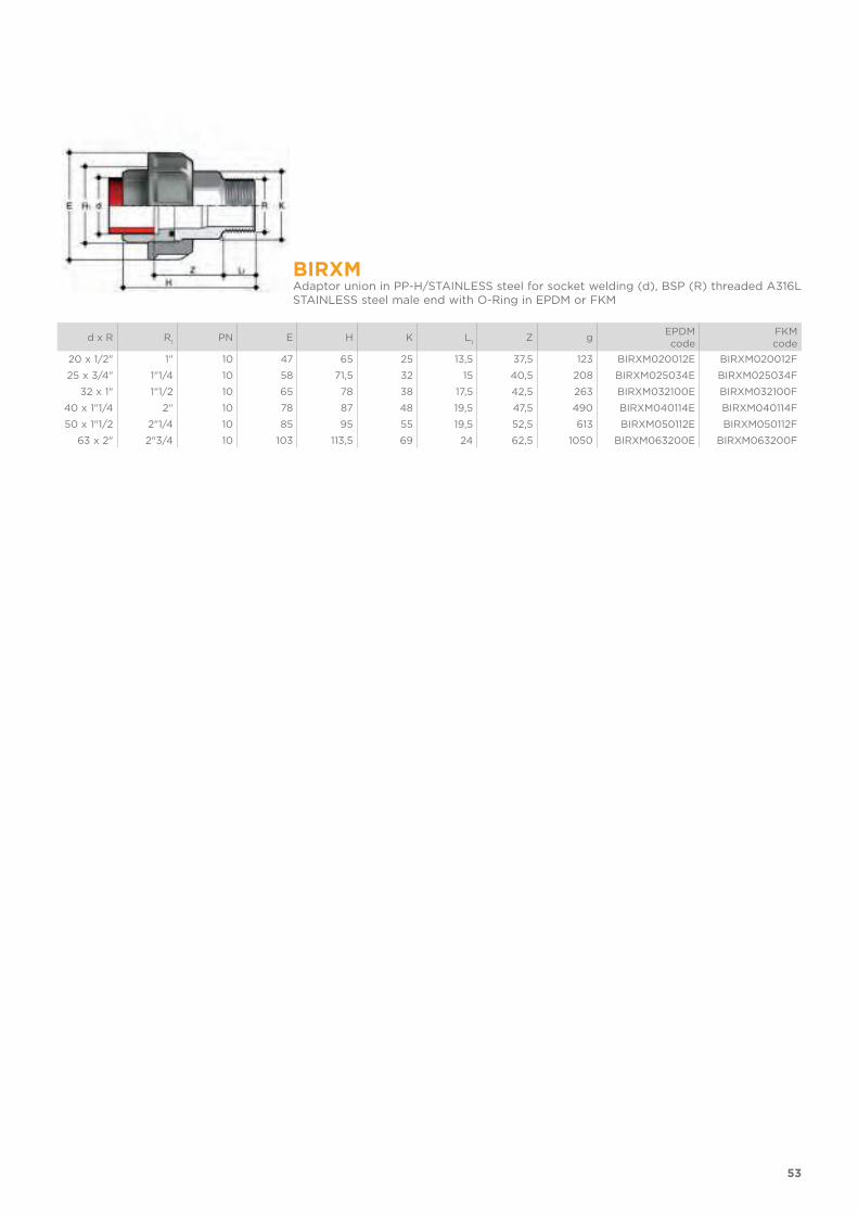
53
BIRXMAdaptor union in PP-H/STAINLESS steel for socket welding (d), BSP (R) threaded A316L STAINLESS steel male end with O-Ring in EPDM or FKM
d x R R1
PN E H K L1
Z gEPDM code
FKM code
20 x 1/2" 1" 10 47 65 25 13,5 37,5 123 BIRXM020012E BIRXM020012F
25 x 3/4" 1"1/4 10 58 71,5 32 15 40,5 208 BIRXM025034E BIRXM025034F
32 x 1" 1"1/2 10 65 78 38 17,5 42,5 263 BIRXM032100E BIRXM032100F
40 x 1"1/4 2" 10 78 87 48 19,5 47,5 490 BIRXM040114E BIRXM040114F
50 x 1"1/2 2"1/4 10 85 95 55 19,5 52,5 613 BIRXM050112E BIRXM050112F
63 x 2" 2"3/4 10 103 113,5 69 24 62,5 1050 BIRXM063200E BIRXM063200F
54
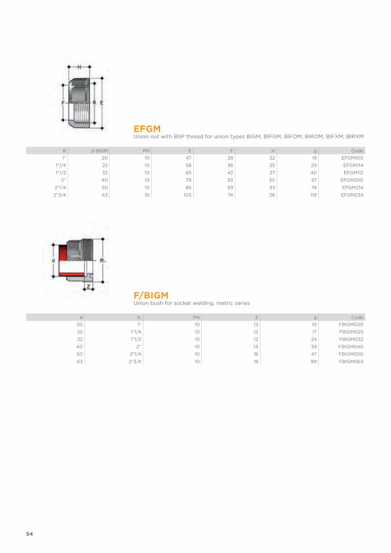
EFGMUnion nut with BSP thread for union types BIGM, BIFGM, BIFOM, BIROM, BIFXM, BIRXM
R d BIGM PN E F H g Code
1" 20 10 47 28 22 19 EFGM100
1"1/4 25 10 58 36 25 29 EFGM114
1"1/2 32 10 65 42 27 40 EFGM112
2" 40 10 78 53 30 57 EFGM200
2"1/4 50 10 85 59 33 74 EFGM214
2"3/4 63 10 103 74 38 119 EFGM234
F/BIGMUnion bush for socket welding, metric series
d R1
PN Z g Code
20 1" 10 12 10 FBIGM020
25 1"1/4 10 12 17 FBIGM025
32 1"1/2 10 12 24 FBIGM032
40 2" 10 14 39 FBIGM040
50 2"1/4 10 16 47 FBIGM050
63 2"3/4 10 18 89 FBIGM063
55
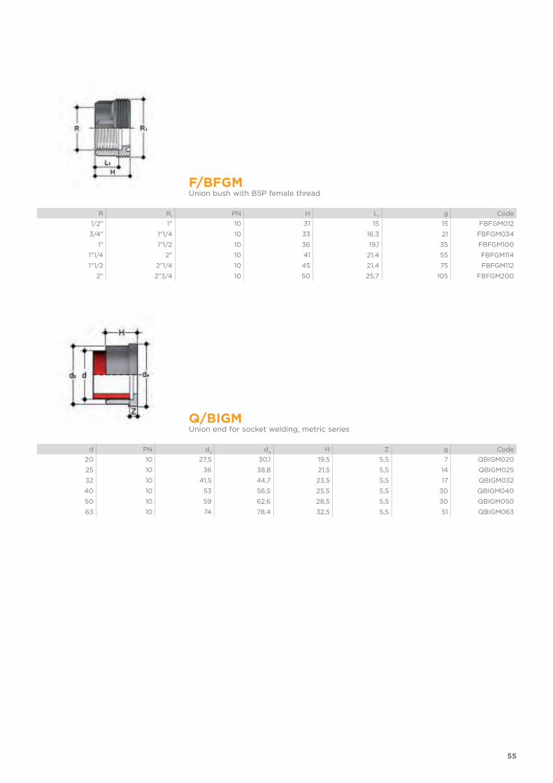
F/BFGMUnion bush with BSP female thread
R R1
PN H L1
g Code
1/2" 1" 10 31 15 15 FBFGM012
3/4" 1"1/4 10 33 16,3 21 FBFGM034
1" 1"1/2 10 36 19,1 35 FBFGM100
1"1/4 2" 10 41 21,4 55 FBFGM114
1"1/2 2"1/4 10 45 21,4 75 FBFGM112
2" 2"3/4 10 50 25,7 105 FBFGM200
Q/BIGMUnion end for socket welding, metric series
d PN d3
d4
H Z g Code
20 10 27,5 30,1 19,5 5,5 7 QBIGM020
25 10 36 38,8 21,5 5,5 14 QBIGM025
32 10 41,5 44,7 23,5 5,5 17 QBIGM032
40 10 53 56,5 25,5 5,5 30 QBIGM040
50 10 59 62,6 28,5 5,5 30 QBIGM050
63 10 74 78,4 32,5 5,5 51 QBIGM063
56
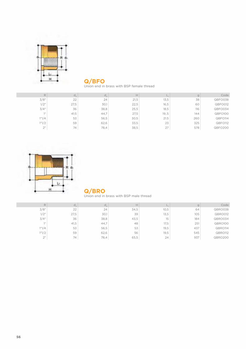
Q/BFOUnion end in brass with BSP female thread
R d3
d4
H L1
g Code
3/8" 22 24 21,5 13,5 38 QBFO038
1/2" 27,5 30,1 22,5 16,5 60 QBFO012
3/4" 36 38,8 25,5 18,5 116 QBFO034
1" 41;5 44,7 27,5 19,.5 144 QBFO100
1"1/4 53 56,5 30,5 21.5 260 QBFO114
1"1/2 59 62,6 33,5 23 325 QBFO112
2" 74 78,4 38,5 27 578 QBFO200
Q/BROUnion end in brass with BSP male thread
R d3
d4
H L1
g Code
3/8" 22 24 34,5 10,5 64 QBRO038
1/2" 27,5 30,1 39 13,5 105 QBRO012
3/4" 36 38,8 43,5 15 184 QBRO034
1" 41,5 44,7 48 17,5 251 QBRO100
1"1/4 53 56,5 53 19,5 437 QBRO114
1"1/2 59 62,6 56 19,5 545 QBRO112
2" 74 78,4 65,5 24 937 QBRO200

57
Q/BFXUnion end in A316L STAINLESS steel with female BSP thread
R d3
d4
H L1
g Code
3/8" 22 24 21,5 13,5 34 QBFX038
1/2" 27,5 30,1 22,5 16,5 54 QBFX012
3/4" 36 38,8 25,5 18,5 104 QBFX034
1" 41,5 44,7 27,5 19,5 130 QBFX100
1"1/4 53 56,5 30,5 21,5 234 QBFX114
1"1/2 59 62,6 33,5 23 293 QBFX112
2" 74 78,4 38,5 27 520 QBFX200
Q/BRXUnion end in A316L STAINLESS steel with male BSP thread
R d3
d4
H L1
g Code
3/8" 22 24 34,5 10,5 58 QBRX038
1/2" 27,5 30,1 39 13,5 95 QBRX012
3/4" 36 38,8 43,5 15 166 QBRX034
1" 41,5 44,7 48 17,5 226 QBRX100
1"1/4 53 56,5 53 19,5 393 QBRX114
1"1/2 59 62,6 56 19,5 491 QBRX112
2" 74 78,4 65,5 24 843 QBRX200

58
O-RINGSeals for union types BIGM, BIFGM, BIFOM, BIROM, BIFXM, BIRXM
d union C di T EPDM code FKM code
16 3062 15,54 2,62 OR3062E OR3062F
20 4081 20,22 3,53 OR4081E OR4081F
25 4112 28,17 3,53 OR4112E OR4112F
32 4131 32,93 3,53 OR4131E OR4131F
40 6162 40,65 5,34 OR6162E OR6162F
50 6187 47 5,34 OR6187E OR6187F
63 6237 59,69 5,34 OR6237E OR6237F
75 6300 75,57 5,34 OR6300E OR6300F
90 6362 91,45 5,34 OR6362E OR6362F
110 6450 113,67 5,34 OR6450E OR6450F


FITTINGS
FOR BUTT WELDING
PP-H
Fittings, metric series ISO-UNI

FITTINGSFOR BUTT WELDING
FITTINGS, METRIC SERIES ISO-UNISeries of fittings designed for conveying fluids under pressure with a weld connection system (butt welding).
Technical specifications
Size range d 20 ÷ d 630 (mm)
Nominal pressure SDR 17, 6 (PN6) with water at 20 °CSDR 11 (PN10) with water at 20 °C
Temperature range 0 °C ÷ 100 °C
Coupling standards Welding: EN ISO 15494. Can be coupled to pipes according to EN ISO 15494
Flanging system: ISO 7005-1, EN 1092-1, EN ISO 15494, DIN 2501, ANSI B16.5 cl.150
Reference standards Construction criteria: EN ISO 15494
Test methods and requirements: EN ISO 15494
Installation criteria: DVS 2202-1, DVS 2207-11, DVS 2208-1, UNI 11397
Fitting material PP-H
Seal material EPDM, FKM
62
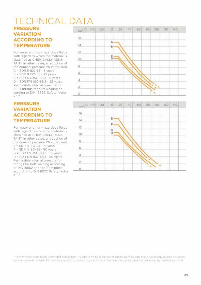
PRESSURE VARIATION ACCORDING TO TEMPERATURE
For water and non-hazardous fluids with regard to which the material is classified as CHEMICALLY RESIS-TANT. In other cases, a reduction of the nominal pressure PN is required.A = SDR 11 ISO-S5 - 5 yearsB = SDR 11 ISO-S5 - 25 yearsC = SDR 17.6 ISO-S8.3 - 5 yearsD = SDR 17.6 ISO-S8.3 - 25 yearsPermissible internal pressure for PP-H fittings for butt welding ac-cording to DIN 16962. Safety factor = 1.7
PRESSURE VARIATION ACCORDING TO TEMPERATURE
For water and non-hazardous fluids with regard to which the material is classified as CHEMICALLY RESIS-TANT. In other cases, a reduction of the nominal pressure PN is required.E = SDR 11 ISO-S5 - 10 yearsF = SDR 11 ISO-S5 - 50 yearsG = SDR 17.6 ISO-S8.3 - 10 yearsH = SDR 17.6 ISO-S8.3 - 50 yearsPermissible internal pressure for fittings for butt welding according to DIN 16962 and for PP-H pipes according to DIN 8077. Safety factor = 1.7
The information in this leaflet is provided in good faith. No liability will be accepted concerning technical data that is not directly covered by recogni-
sed international standards. FIP reserves the right to carry out any modification. Products must be installed and maintained by qualified personnel.
63
TECHNICAL DATA

64
DIMENSIONS
GBM90° bend, short spigot for butt welding SDR 17,6 - 8,3
d l r s Z gPN6 code
SDR 17,6 - S 8,3
50 7 55 2,9 62 47 GBM17050
63 8 69 3,6 77 89 GBM17063
75 10 75 4,3 85 152 GBM17075
90 10 90 5,1 100 245 GBM17090
110 10 110 6,3 120 422 GBM17110
125 15 125 7,1 140 652 GBM17125
140 15 140 8 155 900 GBM17140
160 15 160 9,1 175 1231 GBM17160
180 15 180 10,2 195 1875 GBM17180
200 15 200 11,4 215 2423 GBM17200
225 20 225 12,8 245 3469 GBM17225
250 25 250 14,2 275 4568 GBM17250
280 30 280 15,9 310 6550 GBM17280
315 35 315 17,9 350 9728 GBM17315
355 38 355 20,1 385 19365 GBM17355S
400 41 400 22,7 438 28650 GBM17400S
450 60 450 25,5 510 52551 GBM17450S
500 60 500 28,3 560 28650 GBM17500S
65
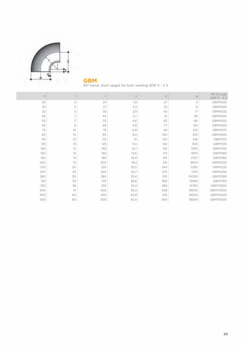
GBM90° bend, short spigot for butt welding SDR 11 - S 5
d l r s Z gPN 10 codeSDR 11 - S 5
20 3 24 1,9 27 5 GBM11020
25 5 27 2,3 32 9 GBM11025
32 5 35 2,9 40 17 GBM11032
40 7 44 3,7 51 36 GBM11040
50 7 55 4,6 62 66 GBM11050
63 8 69 5,8 77 124 GBM11063
75 10 75 6,8 85 210 GBM11075
90 10 90 8,2 100 355 GBM11090
110 10 110 10 120 616 GBM11110
125 15 125 11,4 140 945 GBM11125
140 15 140 12,7 155 1300 GBM11140
160 15 160 14,6 175 1870 GBM11160
180 15 180 16,4 195 2767 GBM11180
200 15 200 18,2 215 3604 GBM11200
225 20 225 20,5 245 5292 GBM11225
250 25 250 22,7 275 7210 GBM11250
280 30 280 25,4 310 10020 GBM11280
315 35 315 28,6 350 13965 GBM11315
355 38 355 32,2 385 12760 GBM11355S
400 41 400 36,3 438 18500 GBM11400S
450 60 450 40,9 510 18500 GBM11450S
500 60 500 45,4 560 18500 GBM11500S
66
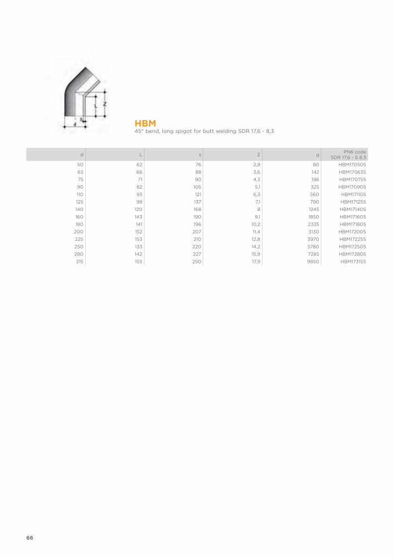
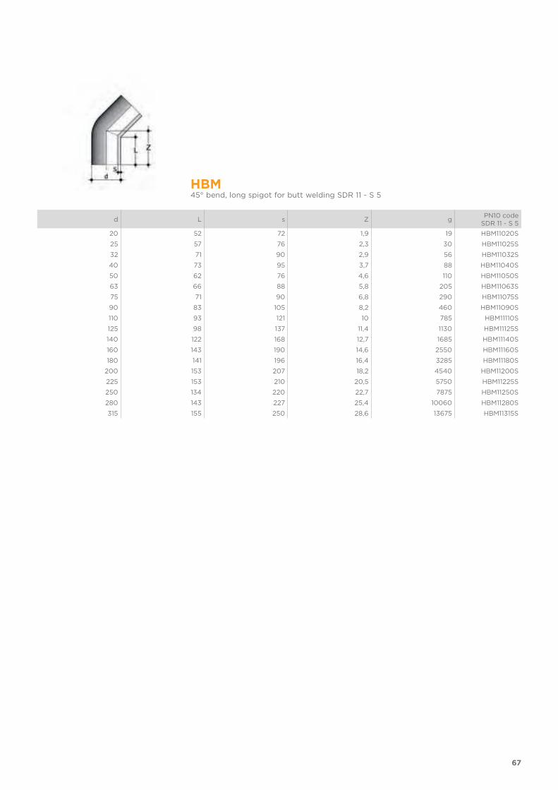
HBM45° bend, long spigot for butt welding SDR 17,6 - 8,3
d L s Z gPN6 code
SDR 17,6 - S 8,3
50 62 76 2,9 80 HBM17050S
63 66 88 3,6 142 HBM17063S
75 71 90 4,3 196 HBM17075S
90 82 105 5,1 325 HBM17090S
110 93 121 6,3 560 HBM17110S
125 98 137 7,1 790 HBM17125S
140 120 168 8 1245 HBM17140S
160 143 190 9,1 1850 HBM17160S
180 141 196 10,2 2335 HBM17180S
200 152 207 11,4 3130 HBM17200S
225 153 210 12,8 3970 HBM17225S
250 133 220 14,2 5780 HBM17250S
280 142 227 15,9 7285 HBM17280S
315 155 250 17,9 9850 HBM17315S
67
HBM45° bend, long spigot for butt welding SDR 11 - S 5
d L s Z gPN10 code
SDR 11 - S 5
20 52 72 1,9 19 HBM11020S
25 57 76 2,3 30 HBM11025S
32 71 90 2,9 56 HBM11032S
40 73 95 3,7 88 HBM11040S
50 62 76 4,6 110 HBM11050S
63 66 88 5,8 205 HBM11063S
75 71 90 6,8 290 HBM11075S
90 83 105 8,2 460 HBM11090S
110 93 121 10 785 HBM11110S
125 98 137 11,4 1130 HBM11125S
140 122 168 12,7 1685 HBM11140S
160 143 190 14,6 2550 HBM11160S
180 141 196 16,4 3285 HBM11180S
200 153 207 18,2 4540 HBM11200S
225 153 210 20,5 5750 HBM11225S
250 134 220 22,7 7875 HBM11250S
280 143 227 25,4 10060 HBM11280S
315 155 250 28,6 13675 HBM11315S
68
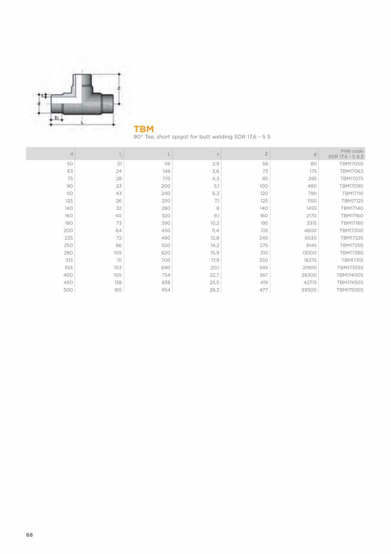
TBM90° Tee, short spigot for butt welding SDR 17,6 - S 5
d I1
L s Z gPN6 code
SDR 17,6 - S 8,3
50 21 116 2,9 58 80 TBM17050
63 24 146 3,6 73 175 TBM17063
75 28 170 4,3 85 295 TBM17075
90 23 200 5,1 100 480 TBM17090
110 43 240 6,3 120 790 TBM17110
125 26 250 7,1 125 1150 TBM17125
140 32 280 8 140 1455 TBM17140
160 40 320 9,1 160 2170 TBM17160
180 73 390 10,2 195 3315 TBM17180
200 64 430 11,4 215 4600 TBM17200
225 72 490 12,8 245 6530 TBM17225
250 86 550 14,2 275 8145 TBM17250
280 105 620 15,9 310 13000 TBM17280
315 111 700 17,9 350 18375 TBM17315
355 103 690 20,1 345 21900 TBM17355S
400 105 734 22,7 367 26300 TBM17400S
450 138 838 25,5 419 42715 TBM17450S
500 165 954 28,3 477 59500 TBM17500S
69
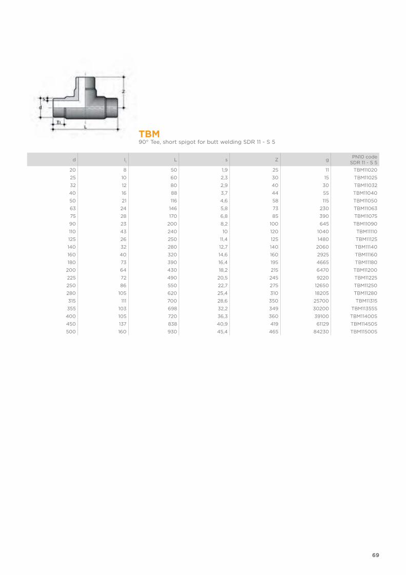
TBM90° Tee, short spigot for butt welding SDR 11 - S 5
d I1
L s Z gPN10 code
SDR 11 - S 5
20 8 50 1,9 25 11 TBM11020
25 10 60 2,3 30 15 TBM11025
32 12 80 2,9 40 30 TBM11032
40 16 88 3,7 44 55 TBM11040
50 21 116 4,6 58 115 TBM11050
63 24 146 5,8 73 230 TBM11063
75 28 170 6,8 85 390 TBM11075
90 23 200 8,2 100 645 TBM11090
110 43 240 10 120 1040 TBM11110
125 26 250 11,4 125 1480 TBM11125
140 32 280 12,7 140 2060 TBM11140
160 40 320 14,6 160 2925 TBM11160
180 73 390 16,4 195 4665 TBM11180
200 64 430 18,2 215 6470 TBM11200
225 72 490 20,5 245 9220 TBM11225
250 86 550 22,7 275 12650 TBM11250
280 105 620 25,4 310 18205 TBM11280
315 111 700 28,6 350 25700 TBM11315
355 103 698 32,2 349 30200 TBM11355S
400 105 720 36,3 360 39100 TBM11400S
450 137 838 40,9 419 61129 TBM11450S
500 160 930 45,4 465 84230 TBM11500S
70
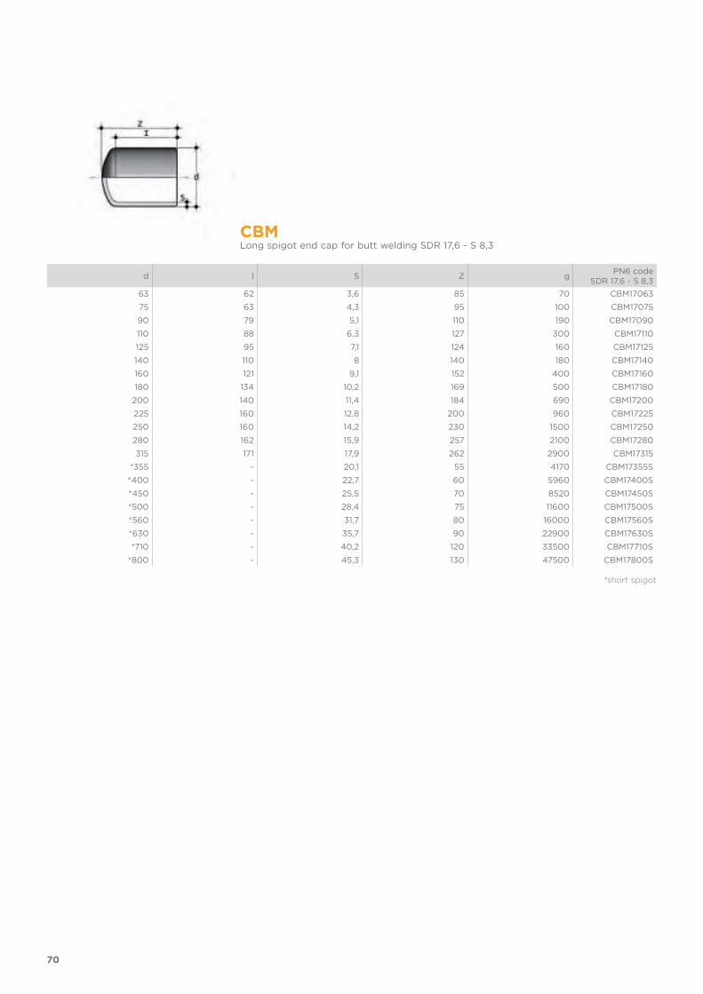
CBMLong spigot end cap for butt welding SDR 17,6 - S 8,3
d I S Z gPN6 code
SDR 17,6 - S 8,3
63 62 3,6 85 70 CBM17063
75 63 4,3 95 100 CBM17075
90 79 5,1 110 190 CBM17090
110 88 6,3 127 300 CBM17110
125 95 7,1 124 160 CBM17125
140 110 8 140 180 CBM17140
160 121 9,1 152 400 CBM17160
180 134 10,2 169 500 CBM17180
200 140 11,4 184 690 CBM17200
225 160 12,8 200 960 CBM17225
250 160 14,2 230 1500 CBM17250
280 162 15,9 257 2100 CBM17280
315 171 17,9 262 2900 CBM17315
*355 - 20,1 55 4170 CBM17355S
*400 - 22,7 60 5960 CBM17400S
*450 - 25,5 70 8520 CBM17450S
*500 - 28,4 75 11600 CBM17500S
*560 - 31,7 80 16000 CBM17560S
*630 - 35,7 90 22900 CBM17630S
*710 - 40,2 120 33500 CBM17710S
*800 - 45,3 130 47500 CBM17800S
*short spigot
71
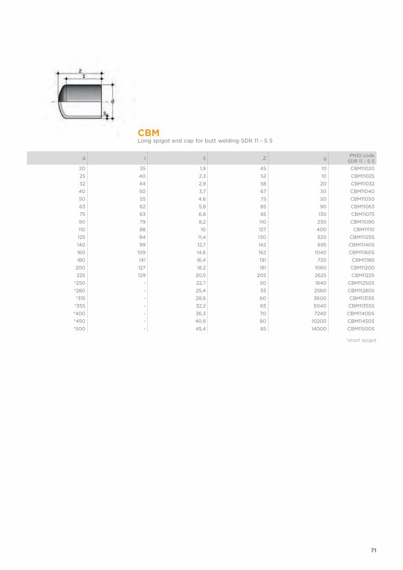
CBMLong spigot end cap for butt welding SDR 11 - S 5
d I S Z gPN10 code
SDR 11 - S 5
20 35 1,9 45 10 CBM11020
25 40 2,3 52 10 CBM11025
32 44 2,9 58 20 CBM11032
40 50 3,7 67 30 CBM11040
50 55 4,6 75 50 CBM11050
63 62 5,8 85 90 CBM11063
75 63 6,8 95 130 CBM11075
90 79 8,2 110 230 CBM11090
110 88 10 127 400 CBM11110
125 94 11,4 130 520 CBM11125S
140 99 12,7 142 695 CBM11140S
160 109 14,6 162 1040 CBM11160S
180 141 16,4 191 730 CBM11180
200 127 18,2 181 1060 CBM11200
225 129 20,5 205 2625 CBM11225
*250 - 22,7 50 1840 CBM11250S
*280 - 25,4 55 2560 CBM11280S
*315 - 28,6 60 3600 CBM11315S
*355 - 32,2 65 5040 CBM11355S
*400 - 36,3 70 7240 CBM11400S
*450 - 40,9 80 10200 CBM11450S
*500 - 45,4 85 14000 CBM11500S
*short spigot

72
BBM-LLong spigot union for butt welding with seal in EPDM or FKM
d DN R1
E SDR 11 - S5 S Z g*EPDM codeSDR 11 - S 5
**FKM codeSDR 11 - S 5
20 15 1" 46 1,9 190 70 BBML11020E BBML11020F
25 20 1"1/4 56 2,3 190 105 BBML11025E BBML11025F
32 25 1"1/2 66 2,9 190 140 BBML11032E BBML11032F
40 32 2" 79 3,7 190 210 BBML11040E BBML11040F
50 40 2"1/4 87 4,6 190 295 BBML11050E BBML11050F
63 50 2"3/4 107 5,8 190 480 BBML11063E BBML11063F
* EPDM O-ring** FKM O-ring
Q/BBM-LUnion end, long spigot, for butt welding for union BBM-L
d d3
d4
h SDR 11 - S 5 S Z Z gPN10 code
SDR 11 - S 5
20 27,4 30 5 1,9 95 20 QBBML11020
25 35,9 38,7 6 2,3 95 40 QBBML11025
32 41,4 44,6 6 2,9 95 45 QBBML11032
40 52,8 56,4 7 3,7 95 75 QBBML11040
50 58,8 62,5 7 4,6 95 110 QBBML11050
63 73,8 78,3 8 5,8 95 160 QBBML11063
75 83 96,7 9 6,8 130 290 QBBML11075
90 98 109,4 10 8,2 150 357 QBBML11090
110 118 134,8 11 10 170 630 QBBML11110
73
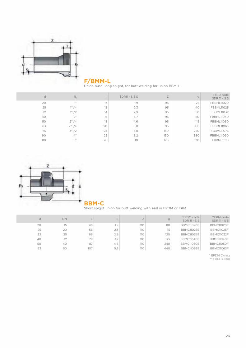
F/BMM-LUnion bush, long spigot, for butt welding for union BBM-L
d R1
I SDR11 - S 5 S Z gPN10 code
SDR 11 - S 5
20 1" 13 1,9 95 25 FBBML11020
25 1"1/4 13 2,3 95 40 FBBML11025
32 1"1/2 14 2,9 95 50 FBBML11032
40 2" 16 3,7 95 80 FBBML11040
50 2"1/4 18 4,6 95 115 FBBML11050
63 2"3/4 20 5,8 95 185 FBBML11063
75 3"1/2 24 6,8 130 250 FBBML11075
90 4" 25 8,2 150 380 FBBML11090
110 5" 28 10 170 630 FBBML11110
BBM-CShort spigot union for butt welding with seal in EPDM or FKM
d DN E S Z g*EPDM codeSDR 11 - S 5
**FKM codeSDR 11 - S 5
20 15 46 1,9 110 80 BBMC11020E BBMC11020F
25 20 56 2,3 110 75 BBMC11025E BBMC11025F
32 25 66 2,9 110 120 BBMC11032E BBMC11032F
40 32 79 3,7 110 175 BBMC11040E BBMC11040F
50 40 87 4,6 110 240 BBMC11050E BBMC11050F
63 50 107 5,8 110 440 BBMC11063E BBMC11063F
* EPDM O-ring** FKM O-ring
74
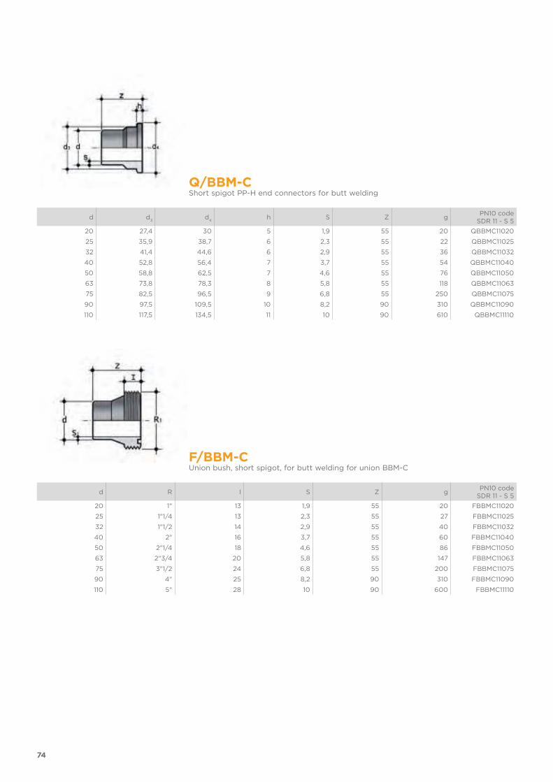
Q/BBM-CShort spigot PP-H end connectors for butt welding
d d3
d4
h S Z gPN10 code
SDR 11 - S 5
20 27,4 30 5 1,9 55 20 QBBMC11020
25 35,9 38,7 6 2,3 55 22 QBBMC11025
32 41,4 44,6 6 2,9 55 36 QBBMC11032
40 52,8 56,4 7 3,7 55 54 QBBMC11040
50 58,8 62,5 7 4,6 55 76 QBBMC11050
63 73,8 78,3 8 5,8 55 118 QBBMC11063
75 82,5 96,5 9 6,8 55 250 QBBMC11075
90 97,5 109,5 10 8,2 90 310 QBBMC11090
110 117,5 134,5 11 10 90 610 QBBMC11110
F/BBM-CUnion bush, short spigot, for butt welding for union BBM-C
d R I S Z gPN10 code
SDR 11 - S 5
20 1" 13 1,9 55 20 FBBMC11020
25 1"1/4 13 2,3 55 27 FBBMC11025
32 1"1/2 14 2,9 55 40 FBBMC11032
40 2" 16 3,7 55 60 FBBMC11040
50 2"1/4 18 4,6 55 86 FBBMC11050
63 2"3/4 20 5,8 55 147 FBBMC11063
75 3"1/2 24 6,8 55 200 FBBMC11075
90 4" 25 8,2 90 310 FBBMC11090
110 5" 28 10 90 600 FBBMC11110
75
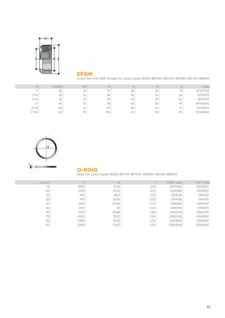
EFGMUnion nut with BSP thread for union types BIGM, BIFGM, BIFOM, BIROM, BIFXM, BIRXM
R d BIGM PN E F H g Code
1" 20 10 47 28 22 19 EFGM100
1"1/4 25 10 58 36 25 29 EFGM114
1"1/2 32 10 65 42 27 40 EFGM112
2" 40 10 78 53 30 57 EFGM200
2"1/4 50 10 85 59 33 74 EFGM214
2"3/4 63 10 103 74 38 119 EFGM234
O-RINGSeals for union types BIGM, BIFGM, BIFOM, BIROM, BIFXM, BIRXM
d union C di T EPDM code FKM code
16 3062 15,54 2,62 OR3062E OR3062F
20 4081 20,22 3,53 OR4081E OR4081F
25 4112 28,17 3,53 OR4112E OR4112F
32 4131 32,93 3,53 OR4131E OR4131F
40 6162 40,65 5,34 OR6162E OR6162F
50 6187 47 5,34 OR6187E OR6187F
63 6237 59,69 5,34 OR6237E OR6237F
75 6300 75,57 5,34 OR6300E OR6300F
90 6362 91,45 5,34 OR6362E OR6362F
110 6450 113,67 5,34 OR6450E OR6450F
76
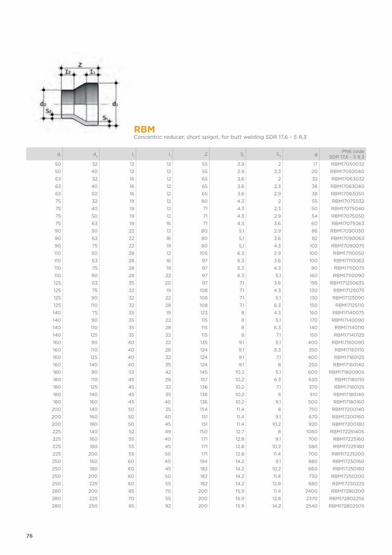
RBMConcentric reducer, short spigot, for butt welding SDR 17,6 - S 8,3
d1
d2
l1
l1
Z S1
S2
gPN6 code
SDR 17,6 - S 8,3
50 32 12 12 55 2.9 2 17 RBM17050032
50 40 12 12 55 2.9 2,3 20 RBM17050040
63 32 16 12 65 3.6 2 32 RBM17063032
63 40 16 12 65 3.6 2,3 36 RBM17063040
63 50 16 12 65 3.6 2.9 38 RBM17063050
75 32 19 12 80 4.3 2 55 RBM17075032
75 40 19 12 71 4.3 2,3 50 RBM17075040
75 50 19 12 71 4.3 2.9 54 RBM17075050
75 63 19 16 71 4.3 3.6 60 RBM17075063
90 50 22 12 80 5,1 2.9 86 RBM17090050
90 63 22 16 80 5,1 3.6 82 RBM17090063
90 75 22 19 80 5,1 4.3 102 RBM17090075
110 50 28 12 105 6.3 2.9 100 RBM17110050
110 63 28 16 97 6.3 3.6 100 RBM17110063
110 75 28 19 97 6.3 4.3 90 RBM17110075
110 90 28 22 97 6.3 5,1 160 RBM17110090
125 63 35 20 97 7.1 3.6 195 RBM17125063S
125 75 32 19 108 7.1 4.3 130 RBM17125075
125 90 32 22 108 7.1 5,1 130 RBM17125090
125 110 32 28 108 7.1 6.3 150 RBM17125110
140 75 35 19 123 8 4.3 160 RBM17140075
140 90 35 22 115 8 5,1 170 RBM17140090
140 110 35 28 115 8 6.3 140 RBM17140110
140 125 35 32 115 8 7.1 150 RBM17140125
160 90 40 22 135 9.1 5,1 400 RBM17160090
160 110 40 28 124 9.1 6.3 350 RBM17160110
160 125 40 32 124 9.1 7.1 400 RBM17160125
160 140 40 35 124 9.1 8 250 RBM17160140
180 90 53 42 145 10.2 5.1 600 RBM17180090S
180 110 45 28 157 10,2 6.3 630 RBM17180110
180 125 45 32 136 10,2 7.1 370 RBM17180125
180 140 45 35 136 10,2 8 510 RBM17180140
180 160 45 40 136 10,2 9.1 500 RBM17180160
200 140 50 35 154 11.4 8 750 RBM17200140
200 160 50 40 151 11.4 9.1 670 RBM17200160
200 180 50 45 151 11.4 10,2 920 RBM17200180
225 140 52 49 150 12.7 8 1060 RBM17225140S
225 160 55 40 171 12.8 9.1 700 RBM17225160
225 180 55 45 171 12.8 10,2 580 RBM17225180
225 200 55 50 171 12.8 11.4 700 RBM17225200
250 160 60 40 194 14.2 9.1 880 RBM17250160
250 180 60 45 182 14.2 10,2 660 RBM17250180
250 200 60 50 182 14.2 11.4 730 RBM17250200
250 225 60 55 182 14.2 12.8 680 RBM17250225
280 200 85 70 200 15.9 11.4 2400 RBM17280200
280 225 70 55 200 15.9 12.8 2370 RBM17280225S
280 250 85 92 200 15.9 14.2 2540 RBM17280250S
77
d
1d
2l1
l1
Z S1
S2
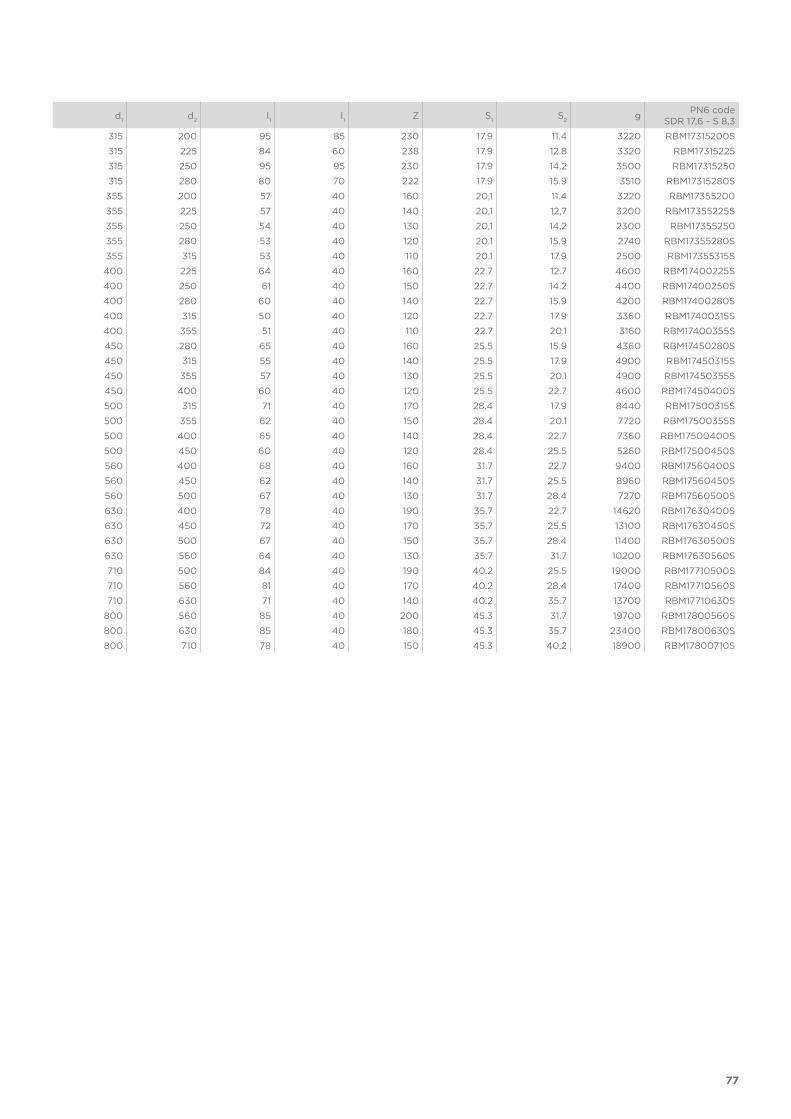
gPN6 code
SDR 17,6 - S 8,3
315 200 95 85 230 17.9 11.4 3220 RBM17315200S
315 225 84 60 238 17.9 12.8 3320 RBM17315225
315 250 95 95 230 17.9 14.2 3500 RBM17315250
315 280 80 70 222 17.9 15.9 3510 RBM17315280S
355 200 57 40 160 20,1 11.4 3220 RBM17355200
355 225 57 40 140 20,1 12,7 3200 RBM17355225S
355 250 54 40 130 20,1 14,2 2300 RBM17355250
355 280 53 40 120 20.1 15.9 2740 RBM17355280S
355 315 53 40 110 20.1 17.9 2500 RBM17355315S
400 225 64 40 160 22.7 12.7 4600 RBM17400225S
400 250 61 40 150 22.7 14.2 4400 RBM17400250S
400 280 60 40 140 22.7 15.9 4200 RBM17400280S
400 315 50 40 120 22.7 17.9 3360 RBM17400315S
400 355 51 40 110 22.7 20.1 3160 RBM17400355S
450 280 65 40 160 25.5 15.9 4360 RBM17450280S
450 315 55 40 140 25.5 17.9 4900 RBM17450315S
450 355 57 40 130 25.5 20.1 4900 RBM17450355S
450 400 60 40 120 25.5 22.7 4600 RBM17450400S
500 315 71 40 170 28.4 17.9 8440 RBM17500315S
500 355 62 40 150 28.4 20.1 7720 RBM17500355S
500 400 65 40 140 28.4 22.7 7360 RBM17500400S
500 450 60 40 120 28.4 25.5 5260 RBM17500450S
560 400 68 40 160 31.7 22.7 9400 RBM17560400S
560 450 62 40 140 31.7 25.5 8960 RBM17560450S
560 500 67 40 130 31.7 28.4 7270 RBM17560500S
630 400 78 40 190 35.7 22.7 14620 RBM17630400S
630 450 72 40 170 35.7 25.5 13100 RBM17630450S
630 500 67 40 150 35.7 28.4 11400 RBM17630500S
630 560 64 40 130 35.7 31.7 10200 RBM17630560S
710 500 84 40 190 40.2 25.5 19000 RBM17710500S
710 560 81 40 170 40.2 28.4 17400 RBM17710560S
710 630 71 40 140 40.2 35.7 13700 RBM17710630S
800 560 85 40 200 45.3 31.7 19700 RBM17800560S
800 630 85 40 180 45.3 35.7 23400 RBM17800630S
800 710 78 40 150 45.3 40.2 18900 RBM17800710S

78
RBMConcentric reducer, short spigot, for butt welding SDR 11 - S 5
d1
d2
l1
l1
Z S1
S2
gPN10 code
SDR 11 - S 5
25 20 12 12 37 2,3 1,9 5 RBM11025020
32 20 12 12 43 2,9 1,9 8 RBM11032020
32 25 12 12 43 2,9 2,3 10 RBM11032025
40 20 12 12 50 3,7 1,9 13 RBM11040020
40 25 12 12 50 3,7 2,3 15 RBM11040025
40 32 12 12 50 3,7 3 18 RBM11040032
50 25 12 12 55 4,6 2,3 23 RBM11050025
50 32 12 12 55 4,6 3 25 RBM11050032
50 40 12 12 55 4,6 3,7 29 RBM11050040
63 32 16 12 65 5,8 3 43 RBM11063032
63 40 16 12 65 5,8 3,7 50 RBM11063040
63 50 16 12 65 5,8 4,6 55 RBM11063050
75 32 19 12 80 6,8 3 70 RBM11075032
75 40 19 12 71 6,8 3,7 71 RBM11075040
75 50 19 12 71 6,8 4,6 79 RBM11075050
75 63 19 16 71 6,8 5,8 89 RBM11075063
90 50 22 12 80 8,2 4,6 125 RBM11090050
90 63 22 16 80 8,2 5,8 129 RBM11090063
90 75 22 19 80 8,2 6,9 155 RBM11090075
110 50 28 12 105 10 4,6 150 RBM11110050
110 63 28 16 97 10 5,8 200 RBM11110063
110 75 28 19 97 10 6,9 160 RBM11110075
110 90 28 22 97 10 8,2 140 RBM11110090
125 63 30 16 112 11,4 5,8 180 RBM11125063
125 75 32 19 108 11,4 6,9 200 RBM11125075
125 90 32 22 108 11,4 8,2 200 RBM11125090
125 110 32 28 108 11,4 10 220 RBM11125110
140 75 35 19 123 12,7 6,9 240 RBM11140075
140 90 35 22 115 12,7 8,2 260 RBM11140090
140 110 35 28 115 12,7 10 210 RBM11140110
140 125 35 32 115 12,7 11,4 220 RBM11140125
160 90 48 34 141 14.6 8.2 695 RBM11160090S
160 110 40 28 124 14,6 10 430 RBM11160110
160 125 40 32 124 14,6 11,4 700 RBM11160125
160 140 40 35 124 14,6 12,8 370 RBM11160140
180 90 45 22 157 16,4 8,2 660 RBM11180090
180 110 45 28 157 16,4 10 900 RBM11180110
180 125 45 32 136 16,4 11,4 510 RBM11180125
180 140 45 35 136 16,4 12,8 610 RBM11180140
180 160 45 40 136 16,4 14,6 700 RBM11180160
200 140 50 35 154 18,2 12,8 730 RBM11200140
200 160 50 40 151 18,2 14,6 700 RBM11200160
200 180 50 45 151 18,2 16,4 1300 RBM11200180
225 140 61 48 157 20.5 12.7 1575 RBM11225140S
225 160 55 40 171 20,5 14,6 960 RBM11225160
225 180 55 45 171 20,5 16,4 1020 RBM11225180
225 200 55 50 171 20,5 18,2 1200 RBM11225200
250 160 60 40 194 22,7 14,6 1480 RBM11250160

79
d
1d
2l1
l1
Z S1
S2
gPN10 code
SDR 11 - S 5
250 180 60 45 182 22,7 16,4 1200 RBM11250180
250 200 60 50 182 22,7 18,2 1110 RBM11250200
250 225 60 55 182 22,7 20,5 1040 RBM11250225
280 200 75 54 214 25.4 18.2 3450 RBM11280200S
280 225 72 57 203 25.4 20.5 3425 RBM11280225S
280 250 72 62 202 25.4 22.7 1980 RBM11280250
315 200 80 50 230 28.6 18.2 4520 RBM11315200
315 225 84 60 237 28.6 20.5 5110 RBM11315225S
315 250 86 63 231 28.6 22.7 5105 RBM11315250S
315 280 80 70 222 28.6 25.4 5195 RBM11315280S
355 200 57 40 160 32,3 18,2 4400 RBM11355200
355 225 57 40 140 32,3 20,5 4390 RBM11355225
355 250 54 40 140 32.2 22.7 3940 RBM11355250S
355 280 53 40 120 32.2 25.4 3720 RBM11355280S
355 315 53 40 110 32.2 28.6 3540 RBM11355315S
400 225 64 40 160 36.3 20.5 6100 RBM11400225S
400 250 61 40 150 36.3 22.7 5800 RBM11400250S
400 280 60 40 140 36.3 25.4 5500 RBM11400280S
400 315 50 40 120 36.3 28.6 4660 RBM11400315S
400 355 51 40 110 36.3 32.2 4480 RBM11400355S
450 280 65 40 160 40.9 25.4 9000 RBM11450280S
450 315 55 40 140 40.9 28.6 6720 RBM11450315S
450 355 57 40 130 40.9 32.2 6580 RBM11450355S
450 400 60 40 120 40.9 36.3 6380 RBM11450400S
500 315 71 40 170 45.4 28.6 11000 RBM11500315S
500 355 62 40 150 45.4 32.2 9300 RBM11500355S
500 400 65 40 140 45.4 36.3 9100 RBM11500400S
500 450 60 40 120 45.4 40.9 8300 RBM11500450S
560 400 68 40 160 50.8 36.3 12800 RBM11560400S
560 450 62 40 140 50.8 40.9 12900 RBM11560450S
560 500 67 40 130 50.8 45.4 11400 RBM11560500S
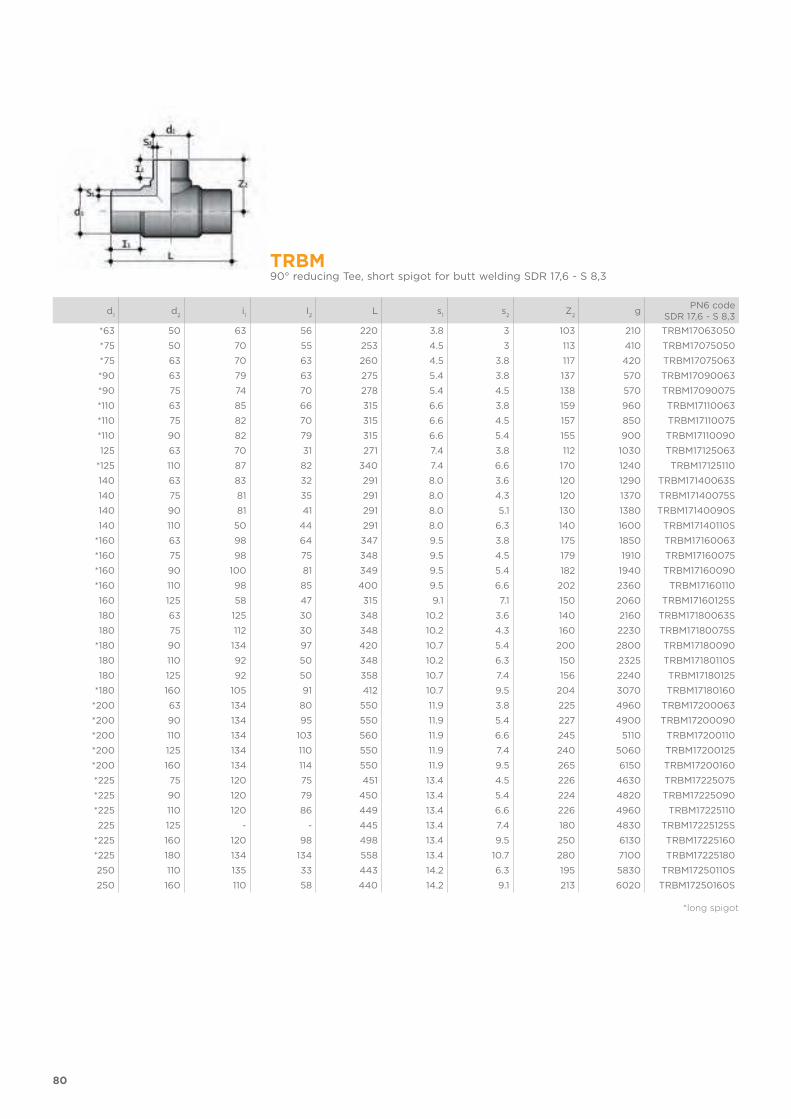
80
TRBM90° reducing Tee, short spigot for butt welding SDR 17,6 - S 8,3
d1
d2
i1
I2
L s1
s2
Z2
gPN6 code
SDR 17,6 - S 8,3
*63 50 63 56 220 3.8 3 103 210 TRBM17063050
*75 50 70 55 253 4.5 3 113 410 TRBM17075050
*75 63 70 63 260 4.5 3.8 117 420 TRBM17075063
*90 63 79 63 275 5.4 3.8 137 570 TRBM17090063
*90 75 74 70 278 5.4 4.5 138 570 TRBM17090075
*110 63 85 66 315 6.6 3.8 159 960 TRBM17110063
*110 75 82 70 315 6.6 4.5 157 850 TRBM17110075
*110 90 82 79 315 6.6 5.4 155 900 TRBM17110090
125 63 70 31 271 7.4 3.8 112 1030 TRBM17125063
*125 110 87 82 340 7.4 6.6 170 1240 TRBM17125110
140 63 83 32 291 8.0 3.6 120 1290 TRBM17140063S
140 75 81 35 291 8.0 4.3 120 1370 TRBM17140075S
140 90 81 41 291 8.0 5.1 130 1380 TRBM17140090S
140 110 50 44 291 8.0 6.3 140 1600 TRBM17140110S
*160 63 98 64 347 9.5 3.8 175 1850 TRBM17160063
*160 75 98 75 348 9.5 4.5 179 1910 TRBM17160075
*160 90 100 81 349 9.5 5.4 182 1940 TRBM17160090
*160 110 98 85 400 9.5 6.6 202 2360 TRBM17160110
160 125 58 47 315 9.1 7.1 150 2060 TRBM17160125S
180 63 125 30 348 10.2 3.6 140 2160 TRBM17180063S
180 75 112 30 348 10.2 4.3 160 2230 TRBM17180075S
*180 90 134 97 420 10.7 5.4 200 2800 TRBM17180090
180 110 92 50 348 10.2 6.3 150 2325 TRBM17180110S
180 125 92 50 358 10.7 7.4 156 2240 TRBM17180125
*180 160 105 91 412 10.7 9.5 204 3070 TRBM17180160
*200 63 134 80 550 11.9 3.8 225 4960 TRBM17200063
*200 90 134 95 550 11.9 5.4 227 4900 TRBM17200090
*200 110 134 103 560 11.9 6.6 245 5110 TRBM17200110
*200 125 134 110 550 11.9 7.4 240 5060 TRBM17200125
*200 160 134 114 550 11.9 9.5 265 6150 TRBM17200160
*225 75 120 75 451 13.4 4.5 226 4630 TRBM17225075
*225 90 120 79 450 13.4 5.4 224 4820 TRBM17225090
*225 110 120 86 449 13.4 6.6 226 4960 TRBM17225110
225 125 - - 445 13.4 7.4 180 4830 TRBM17225125S
*225 160 120 98 498 13.4 9.5 250 6130 TRBM17225160
*225 180 134 134 558 13.4 10.7 280 7100 TRBM17225180
250 110 135 33 443 14.2 6.3 195 5830 TRBM17250110S
250 160 110 58 440 14.2 9.1 213 6020 TRBM17250160S
*long spigot
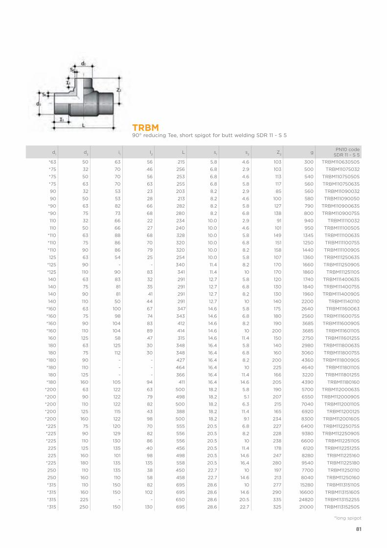
81
TRBM90° reducing Tee, short spigot for butt welding SDR 11 - S 5
d1
d2
i1
I2
L s1
s2
Z2
gPN10 code
SDR 11 - S 5
*63 50 63 56 215 5.8 4.6 103 300 TRBM11063050S
*75 32 70 46 256 6.8 2.9 103 500 TRBM11075032
*75 50 70 56 253 6.8 4.6 113 540 TRBM11075050S
*75 63 70 63 255 6.8 5.8 117 560 TRBM11075063S
90 32 53 23 203 8.2 2.9 85 560 TRBM11090032
90 50 53 28 213 8.2 4.6 100 580 TRBM11090050
*90 63 82 66 282 8.2 5.8 127 790 TRBM11090063S
*90 75 73 68 280 8.2 6.8 138 800 TRBM11090075S
110 32 66 22 234 10.0 2.9 91 940 TRBM11110032
110 50 66 27 240 10.0 4.6 101 950 TRBM11110050S
*110 63 88 68 328 10.0 5.8 149 1345 TRBM11110063S
*110 75 86 70 320 10.0 6.8 151 1250 TRBM11110075S
*110 90 86 79 320 10.0 8.2 158 1440 TRBM11110090S
125 63 54 25 254 10.0 5.8 107 1360 TRBM11125063S
*125 90 - - 340 11.4 8.2 170 1660 TRBM11125090S
*125 110 90 83 341 11.4 10 170 1860 TRBM11125110S
140 63 83 32 291 12.7 5.8 120 1740 TRBM11140063S
140 75 81 35 291 12.7 6.8 130 1840 TRBM11140075S
140 90 81 41 291 12.7 8.2 130 1960 TRBM11140090S
140 110 50 44 291 12.7 10 140 2200 TRBM11140110
*160 63 100 67 347 14.6 5.8 175 2640 TRBM11160063
*160 75 98 74 343 14.6 6.8 180 2560 TRBM11160075S
*160 90 104 83 412 14.6 8.2 190 3685 TRBM11160090S
*160 110 104 89 414 14.6 10 200 3685 TRBM11160110S
160 125 58 47 315 14.6 11.4 150 2750 TRBM11160125S
180 63 125 30 348 16.4 5.8 140 2980 TRBM11180063S
180 75 112 30 348 16.4 6.8 160 3060 TRBM11180075S
*180 90 - - 427 16.4 8.2 200 4360 TRBM11180090S
*180 110 - - 464 16.4 10 225 4640 TRBM11180110S
180 125 - - 366 16.4 11.4 166 3220 TRBM11180125S
*180 160 105 94 411 16.4 14.6 205 4390 TRBM11180160
*200 63 122 63 500 18.2 5.8 190 5700 TRBM11200063S
*200 90 122 79 498 18.2 5.1 207 6550 TRBM11200090S
*200 110 122 82 500 18.2 6.3 215 7040 TRBM11200110S
*200 125 115 43 388 18.2 11.4 165 6920 TRBM11200125
*200 160 122 98 500 18.2 9.1 234 8300 TRBM11200160S
*225 75 120 70 555 20.5 6.8 227 6400 TRBM11225075S
*225 90 129 82 556 20.5 8.2 228 9380 TRBM11225090S
*225 110 130 86 556 20.5 10 238 6600 TRBM11225110S
225 125 135 40 456 20.5 11.4 178 6120 TRBM11225125S
225 160 101 98 498 20.5 14,6 247 8280 TRBM11225160
*225 180 135 135 558 20.5 16,4 280 9540 TRBM11225180
250 110 135 38 450 22.7 10 197 7700 TRBM11250110
250 160 110 58 458 22.7 14.6 213 8040 TRBM11250160
*315 110 150 82 695 28.6 10 277 15280 TRBM11315110S
*315 160 150 102 695 28.6 14.6 290 16600 TRBM11315160S
*315 225 - - 650 28.6 20.5 335 24820 TRBM11315225S
*315 250 150 130 695 28.6 22.7 325 21000 TRBM11315250S
*long spigot
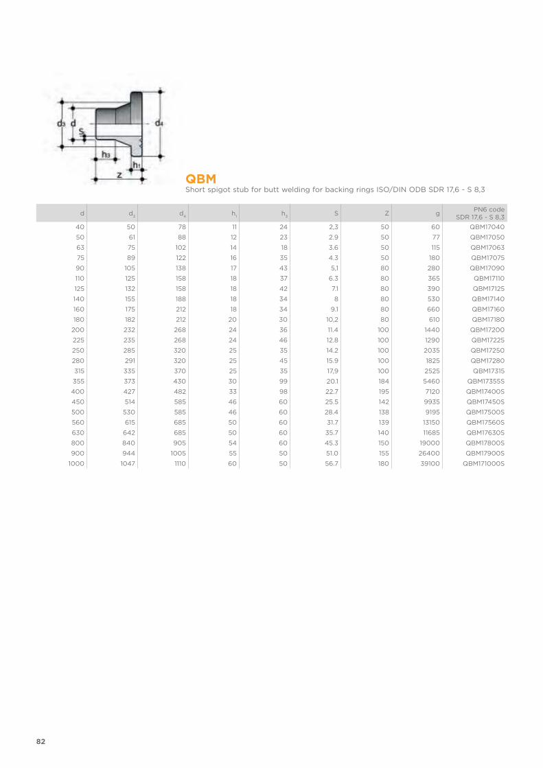
82
QBMShort spigot stub for butt welding for backing rings ISO/DIN ODB SDR 17,6 - S 8,3
d d3
d4
h1
h3
S Z gPN6 code
SDR 17,6 - S 8,3
40 50 78 11 24 2,3 50 60 QBM17040
50 61 88 12 23 2.9 50 77 QBM17050
63 75 102 14 18 3.6 50 115 QBM17063
75 89 122 16 35 4.3 50 180 QBM17075
90 105 138 17 43 5,1 80 280 QBM17090
110 125 158 18 37 6.3 80 365 QBM17110
125 132 158 18 42 7.1 80 390 QBM17125
140 155 188 18 34 8 80 530 QBM17140
160 175 212 18 34 9.1 80 660 QBM17160
180 182 212 20 30 10,2 80 610 QBM17180
200 232 268 24 36 11.4 100 1440 QBM17200
225 235 268 24 46 12.8 100 1290 QBM17225
250 285 320 25 35 14.2 100 2035 QBM17250
280 291 320 25 45 15.9 100 1825 QBM17280
315 335 370 25 35 17,9 100 2525 QBM17315
355 373 430 30 99 20.1 184 5460 QBM17355S
400 427 482 33 98 22.7 195 7120 QBM17400S
450 514 585 46 60 25.5 142 9935 QBM17450S
500 530 585 46 60 28.4 138 9195 QBM17500S
560 615 685 50 60 31.7 139 13150 QBM17560S
630 642 685 50 60 35.7 140 11685 QBM17630S
800 840 905 54 60 45.3 150 19000 QBM17800S
900 944 1005 55 50 51.0 155 26400 QBM17900S
1000 1047 1110 60 50 56.7 180 39100 QBM171000S
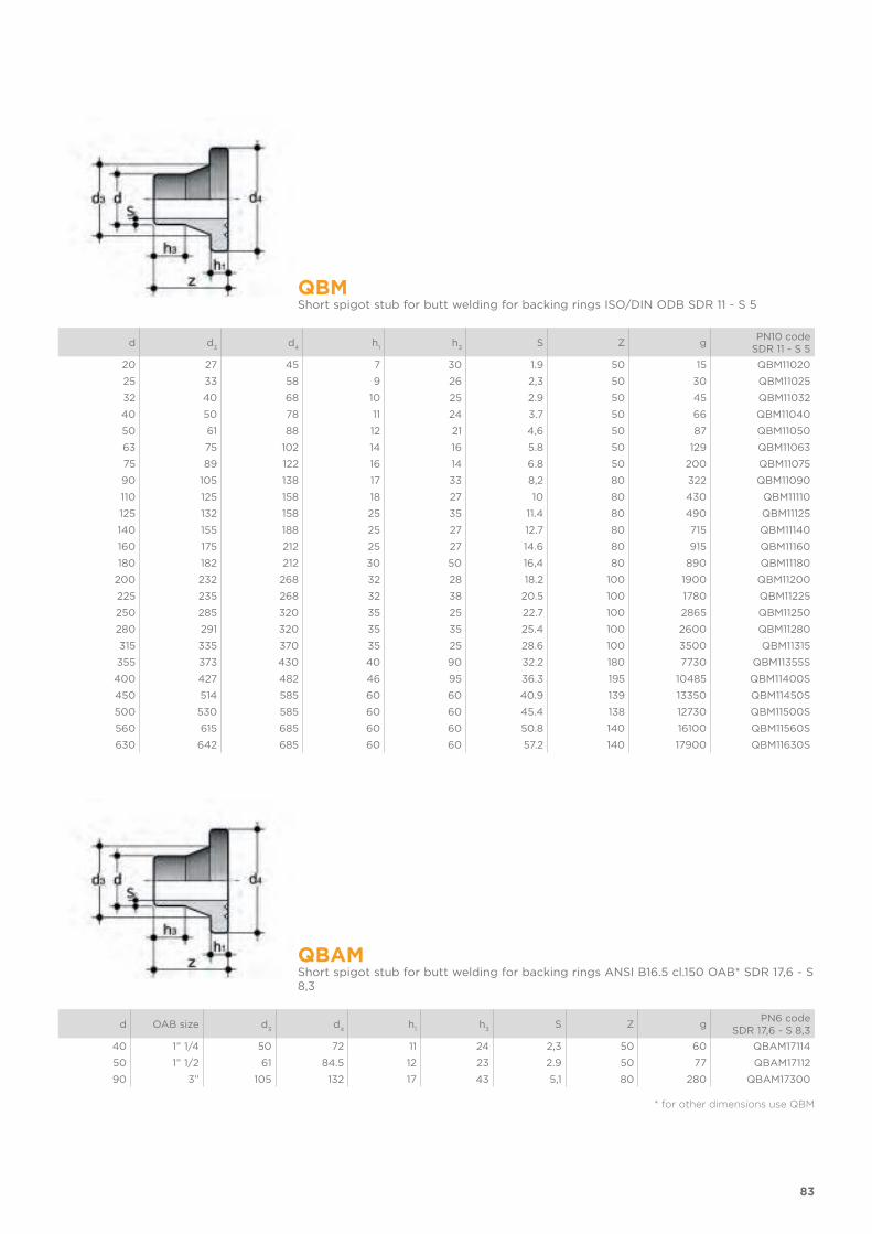
83
QBMShort spigot stub for butt welding for backing rings ISO/DIN ODB SDR 11 - S 5
d d3
d4
h1
h3
S Z gPN10 code
SDR 11 - S 5
20 27 45 7 30 1.9 50 15 QBM11020
25 33 58 9 26 2,3 50 30 QBM11025
32 40 68 10 25 2.9 50 45 QBM11032
40 50 78 11 24 3.7 50 66 QBM11040
50 61 88 12 21 4,6 50 87 QBM11050
63 75 102 14 16 5.8 50 129 QBM11063
75 89 122 16 14 6.8 50 200 QBM11075
90 105 138 17 33 8,2 80 322 QBM11090
110 125 158 18 27 10 80 430 QBM11110
125 132 158 25 35 11.4 80 490 QBM11125
140 155 188 25 27 12.7 80 715 QBM11140
160 175 212 25 27 14.6 80 915 QBM11160
180 182 212 30 50 16,4 80 890 QBM11180
200 232 268 32 28 18.2 100 1900 QBM11200
225 235 268 32 38 20.5 100 1780 QBM11225
250 285 320 35 25 22.7 100 2865 QBM11250
280 291 320 35 35 25.4 100 2600 QBM11280
315 335 370 35 25 28.6 100 3500 QBM11315
355 373 430 40 90 32.2 180 7730 QBM11355S
400 427 482 46 95 36.3 195 10485 QBM11400S
450 514 585 60 60 40.9 139 13350 QBM11450S
500 530 585 60 60 45.4 138 12730 QBM11500S
560 615 685 60 60 50.8 140 16100 QBM11560S
630 642 685 60 60 57.2 140 17900 QBM11630S
QBAMShort spigot stub for butt welding for backing rings ANSI B16.5 cl.150 OAB* SDR 17,6 - S 8,3
d OAB size d3
d4
h1
h3
S Z gPN6 code
SDR 17,6 - S 8,3
40 1” 1/4 50 72 11 24 2,3 50 60 QBAM17114
50 1” 1/2 61 84.5 12 23 2.9 50 77 QBAM17112
90 3” 105 132 17 43 5,1 80 280 QBAM17300
* for other dimensions use QBM
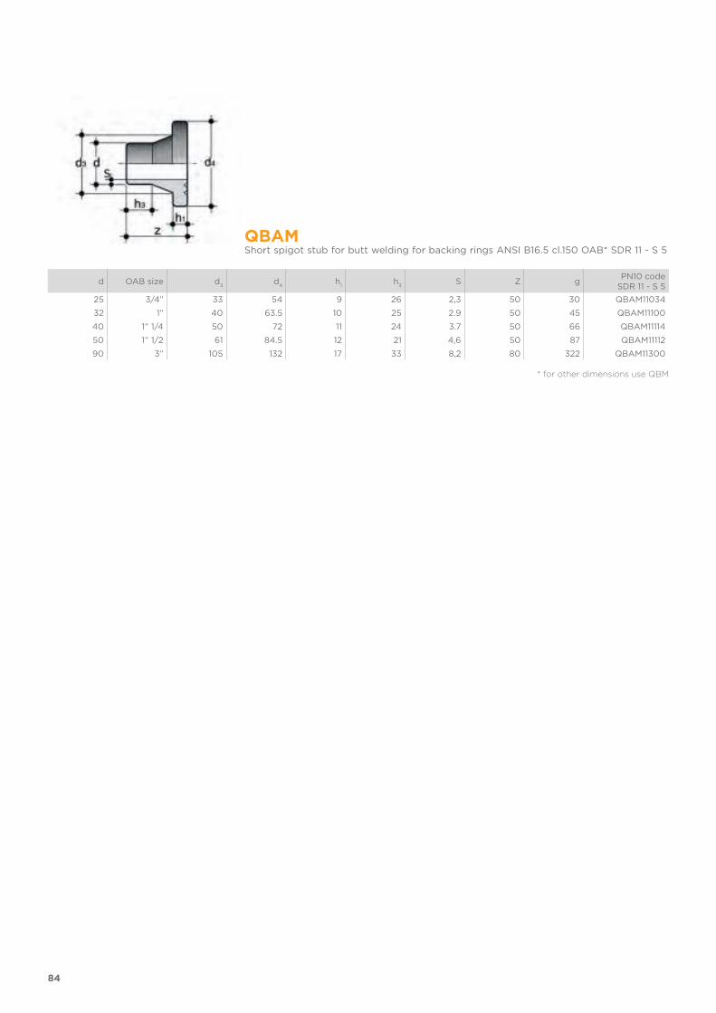
84
QBAMShort spigot stub for butt welding for backing rings ANSI B16.5 cl.150 OAB* SDR 11 - S 5
d OAB size d3
d4
h1
h3
S Z gPN10 code
SDR 11 - S 5
25 3/4” 33 54 9 26 2,3 50 30 QBAM11034
32 1” 40 63.5 10 25 2.9 50 45 QBAM11100
40 1” 1/4 50 72 11 24 3.7 50 66 QBAM11114
50 1” 1/2 61 84.5 12 21 4,6 50 87 QBAM11112
90 3” 105 132 17 33 8,2 80 322 QBAM11300
* for other dimensions use QBM
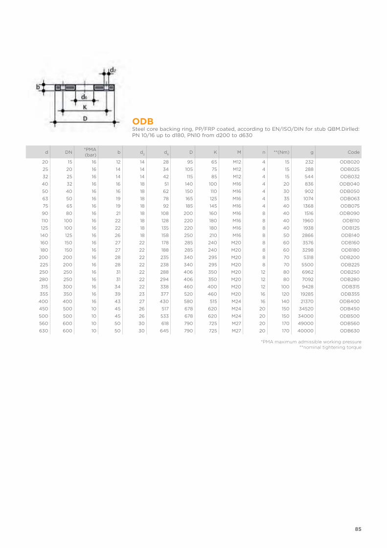
85
ODBSteel core backing ring, PP/FRP coated, according to EN/ISO/DIN for stub QBM.Dirlled: PN 10/16 up to d180, PN10 from d200 to d630
d DN*PMA (bar)
b d2
d6
D K M n **(Nm) g Code
20 15 16 12 14 28 95 65 M12 4 15 232 ODB020
25 20 16 14 14 34 105 75 M12 4 15 288 ODB025
32 25 16 14 14 42 115 85 M12 4 15 544 ODB032
40 32 16 16 18 51 140 100 M16 4 20 836 ODB040
50 40 16 16 18 62 150 110 M16 4 30 902 ODB050
63 50 16 19 18 78 165 125 M16 4 35 1074 ODB063
75 65 16 19 18 92 185 145 M16 4 40 1368 ODB075
90 80 16 21 18 108 200 160 M16 8 40 1516 ODB090
110 100 16 22 18 128 220 180 M16 8 40 1960 ODB110
125 100 16 22 18 135 220 180 M16 8 40 1938 ODB125
140 125 16 26 18 158 250 210 M16 8 50 2866 ODB140
160 150 16 27 22 178 285 240 M20 8 60 3576 ODB160
180 150 16 27 22 188 285 240 M20 8 60 3298 ODB180
200 200 16 28 22 235 340 295 M20 8 70 5318 ODB200
225 200 16 28 22 238 340 295 M20 8 70 5500 ODB225
250 250 16 31 22 288 406 350 M20 12 80 6962 ODB250
280 250 16 31 22 294 406 350 M20 12 80 7092 ODB280
315 300 16 34 22 338 460 400 M20 12 100 9428 ODB315
355 350 16 39 23 377 520 460 M20 16 120 19285 ODB355
400 400 16 43 27 430 580 515 M24 16 140 21370 ODB400
450 500 10 45 26 517 678 620 M24 20 150 34520 ODB450
500 500 10 45 26 533 678 620 M24 20 150 34000 ODB500
560 600 10 50 30 618 790 725 M27 20 170 49000 ODB560
630 600 10 50 30 645 790 725 M27 20 170 40000 ODB630
*PMA maximum admissible working pressure**nominal tightening torque

86
ODBCSteel core blind flange, PP/FRP coated, according to EN/ISO/DIN. Drilling PN 10/16 up to d160/180, PN 10 from d200/225 to d400
d DN*PMA (bar)
b d2
D k M n **(Nm) g Code
20 15 10 16 14 95 65 M12 4 15 290 ODBC020S
25 20 10 12 18 105 75 M12 4 15 380 ODBC025S
32 25 10 18 14 115 85 M12 4 15 600 ODBC032S
40 32 10 17 18 140 100 M16 4 25 830 ODBC040S
50 40 10 18 18 150 110 M16 4 35 1105 ODBC050S
63 50 10 18 18 165 125 M16 4 35 1308 ODBC063S
75 65 10 18 18 185 145 M16 4 40 1580 ODBC075S
90 80 10 20 18 200 160 M16 8 40 2244 ODBC090S
110 100 10 20 18 220 180 M16 8 45 2829 ODBC110S
125 100 10 20 18 220 180 M16 8 45 2873 ODBC125S
140 125 10 24 18 250 210 M16 8 50 3920 ODBC140S
160 150 10 22 22 285 240 M20 8 60 7181 ODBC160S
180 150 10 24 22 285 240 M20 8 60 7130 ODBC180S
200 200 10 24 22 340 295 M20 8 70 10580 ODBC200S
225 200 10 24 22 340 295 M20 8 70 10664 ODBC225S
250 250 10 30 22 395 350 M20 12 100 14040 ODBC250S
280 250 10 30 22 395 350 M20 12 100 14040 ODBC280S
315 300 16 34 22 445 400 M20 12 110 26480 ODBC315S
355 350 10 39 22 505 460 M20 16 160 39000 ODBC355S
400 400 10 46 25 574 515 M24 16 170 50400 ODBC400S
*PMA maximum admissible working pressure**nominal tightening torque

87
OABSteel core backing ring, PP/FRP coated, according to ANSI B16.5 cl.150 for stubs QBM and QBAM
Size DN*PMA (bar)
b d2 mm d2 inch d6
D kmm k inch n **(Nm) g Code
1/2” 15 16 12 16 5/8” 28 95 60.45 2” 3/8 4 15 200 OAB012
3/4” 20 16 12 16 5/8” 34 102 69,85 2” 3/4 4 15 240 OAB034
1” 25 16 16 16 5/8” 42 114 79.25 3” 1/8 4 15 490 OAB100
1” 1/4 32 16 16 16 5/8” 51 130 88.9 3” 1/2 4 25 670 OAB114
1” 1/2 40 16 18 16 5/8” 62 133 98.55 3” 7/8 4 35 640 OAB112
2” 50 16 18 20 3/4” 78 162 120.65 4” 3/4 4 35 1000 OAB200
2” 1/2 65 16 18 20 3/4” 92 184 139,7 5” 1/2 4 40 1310 OAB212
3” 80 16 18 20 3/4” 111 194 152.4 6” 4 40 1250 OAB300
4” 100 16 18 20 3/4” 133 229 190.5 7” 1/2 8 40 1660 OAB400
6” 150 16 24 22 7/8" 178 283 241,3 9"1/2 8 60 3750 OAB600
8” 200 10 24 22 7/8" 236 345 298,45 11"3/4 8 70 5140 OAB800
10” 250 10 27 25 1" 288 412 361,95 14"1/4 12 100 8080 OAB810
12” 315 10 32 25 1" 338 487 431,8 17" 12 110 15380 OAB812
14” 355 10 42 28,5 1"1/8 376 533 476,2 17"3/4 12 110 24940 OAB814
16” 400 10 44 28,5 1"1/8 430 596 539,7 18"13/32 16 110 34770 OAB816
*PMA maximum admissible working pressure**nominal tightening torque
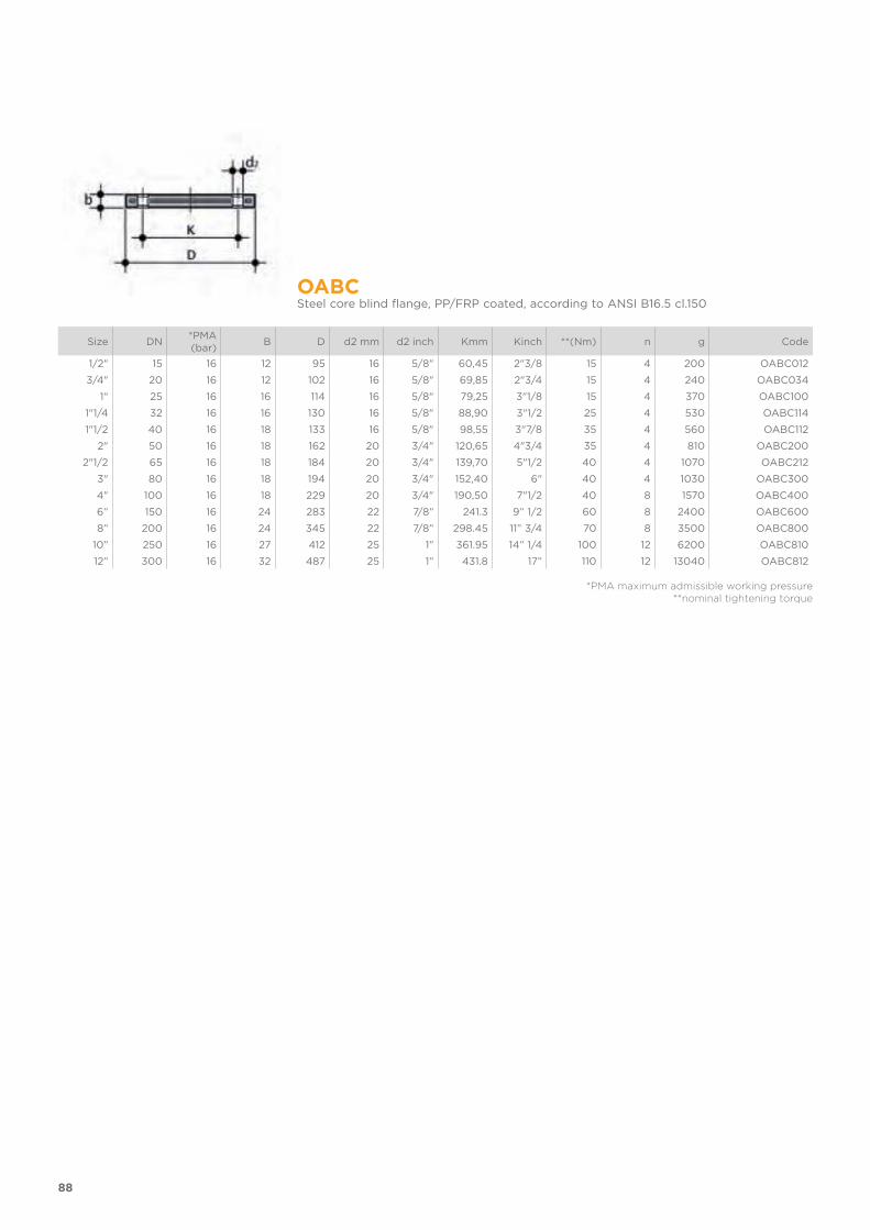
88
OABCSteel core blind flange, PP/FRP coated, according to ANSI B16.5 cl.150
Size DN*PMA (bar)
B D d2 mm d2 inch Kmm Kinch **(Nm) n g Code
1/2" 15 16 12 95 16 5/8" 60,45 2"3/8 15 4 200 OABC012
3/4" 20 16 12 102 16 5/8" 69,85 2"3/4 15 4 240 OABC034
1" 25 16 16 114 16 5/8" 79,25 3"1/8 15 4 370 OABC100
1"1/4 32 16 16 130 16 5/8" 88,90 3"1/2 25 4 530 OABC114
1"1/2 40 16 18 133 16 5/8" 98,55 3"7/8 35 4 560 OABC112
2" 50 16 18 162 20 3/4" 120,65 4"3/4 35 4 810 OABC200
2"1/2 65 16 18 184 20 3/4" 139,70 5"1/2 40 4 1070 OABC212
3" 80 16 18 194 20 3/4" 152,40 6" 40 4 1030 OABC300
4" 100 16 18 229 20 3/4" 190,50 7"1/2 40 8 1570 OABC400
6” 150 16 24 283 22 7/8” 241.3 9” 1/2 60 8 2400 OABC600
8” 200 16 24 345 22 7/8” 298.45 11” 3/4 70 8 3500 OABC800
10” 250 16 27 412 25 1” 361.95 14” 1/4 100 12 6200 OABC810
12” 300 16 32 487 25 1” 431.8 17” 110 12 13040 OABC812
*PMA maximum admissible working pressure**nominal tightening torque
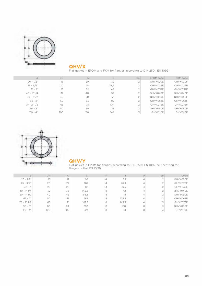
89
QHV/X Flat gasket in EPDM and FKM for flanges according to DIN 2501, EN 1092
d DN A B Sp EPDM code FKM code
20 - 1/2" 15 20 32 2 QHVX020E QHVX020F
25 - 3/4" 20 24 38,5 2 QHVX025E QHVX025F
32 - 1" 25 32 48 2 QHVX032E QHVX032F
40 - 1" 1/4 32 40 59 2 QHVX040E QHVX040F
50 - 1"1/2 40 50 71 2 QHVX050E QHVX050F
63 - 2" 50 63 88 2 QHVX063E QHVX063F
75 - 2" 1/2 65 75 104 2 QHVX075E QHVX075F
90 - 3" 80 90 123 2 QHVX090E QHVX090F
110 - 4" 100 110 148 3 QHVX110E QHVX110F
QHV/YFlat gasket in EPDM for flanges according to DIN 2501, EN 1092, self-centring for flanges drilled PN 10/16
d DN A1
B1
F I U Sp Code
20 - 1/2" 15 17 95 14 65 4 2 QHVY020E
25 - 3/4" 20 22 107 14 76,3 4 2 QHVY025E
32 - 1" 25 28 117 14 86,5 4 2 QHVY032E
40 - 1" 1/4 32 36 142,5 18 101 4 2 QHVY040E
50 - 1" 1/2 40 45 153,3 18 111 4 2 QHVY050E
63 - 2" 50 57 168 18 125,5 4 2 QHVY063E
75 - 2" 1/2 65 71 187,5 18 145,5 4 3 QHVY075E
90 - 3" 80 84 203 18 160 8 3 QHVY090E
110 - 4" 100 102 223 18 181 8 3 QHVY110E

FITTINGS
FOR BUTT WELDING
PP-H
ISO-BSP adaptor fittings
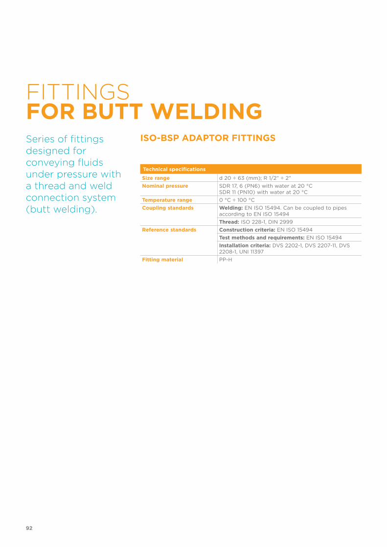
FITTINGSFOR BUTT WELDING
ISO-BSP ADAPTOR FITTINGSSeries of fittings designed for conveying fluids under pressure with a thread and weld connection system (butt welding).
Technical specifications
Size range d 20 ÷ 63 (mm); R 1/2” ÷ 2”
Nominal pressure SDR 17, 6 (PN6) with water at 20 °CSDR 11 (PN10) with water at 20 °C
Temperature range 0 °C ÷ 100 °C
Coupling standards Welding: EN ISO 15494. Can be coupled to pipes according to EN ISO 15494
Thread: ISO 228-1, DIN 2999
Reference standards Construction criteria: EN ISO 15494
Test methods and requirements: EN ISO 15494
Installation criteria: DVS 2202-1, DVS 2207-11, DVS 2208-1, UNI 11397
Fitting material PP-H
92

PRESSURE VARIATION ACCORDING TO TEMPERATURE
For water and non-hazardous fluids with regard to which the material is classified as CHEMICALLY RESIS-TANT. In other cases, a reduction of the nominal pressure PN is required.A = SDR 11 ISO-S5 - 5 yearsB = SDR 11 ISO-S5 - 25 yearsC = SDR 17.6 ISO-S8.3 - 5 yearsD = SDR 17.6 ISO-S8.3 - 25 yearsPermissible internal pressure for PP-H fittings for butt welding ac-cording to DIN 16962. Safety factor = 1.7
PRESSURE VARIATION ACCORDING TO TEMPERATURE
For water and non-hazardous fluids with regard to which the material is classified as CHEMICALLY RESIS-TANT. In other cases, a reduction of the nominal pressure PN is required. E = SDR 11 ISO-S5 - 10 yearsF = SDR 11 ISO-S5 - 50 yearsG = SDR 17.6 ISO-S8.3 - 10 yearsH = SDR 17.6 ISO-S8.3 - 50 yearsPermissible internal pressure for fittings for butt welding according to DIN 16962 and for PP-H pipes according to DIN 8077. Safety factor = 1.7
The information in this leaflet is provided in good faith. No liability will be accepted concerning technical data that is not directly covered by recogni-
sed international standards. FIP reserves the right to carry out any modification. Products must be installed and maintained by qualified personnel.
93
TECHNICAL DATA

94
DIMENSIONS
KBFMDouble adaptor for butt welding (d), BSP (R) threaded male end
d x R I i1
I2
SDR 11 - S 5 S gPN10 code
SDR 11 - S 5
20 x 1/2" 58 38 14 1.9 9 KBFM11020012S
25 x 3/4" 61 41 14 2.3 12 KBFM11025034S
32 x 1" 69 44 18 2.9 22 KBFM11032100S
40 x 1"1/4 75 49 19 3.7 37 KBFM11040114S
50 x 1"1/2 82 55 20 4.6 58 KBFM11050112S
63 x 2" 91 63 21 5.8 95 KBFM11063200S
DBMMDouble adaptor for butt welding (d), BSP (R) threaded female end
d x R K I I1
SDR - S 5 S gPN10 code
SDR 11 - S 5
20 x 1/2” 30 58 39 1.9 16 DBMM11020012S
25 x 3/4” 36 63 41 2.3 22 DBMM11025034S
32 x 1” 46 71 44 2.9 39 DBMM11032100S
40 x 1” 1/4 55 79 49 3.7 58 DBMM11040114S
50 x 1” 1/2 62 84 55 4.6 80 DBMM11050112S
63 x 2” 75 97 63 5.8 140 DBMM11063200S


VKD DN 10÷50
PP-H
DUAL BLOCK® 2-way ball valve

VKD DN 10÷50
DUAL BLOCK® 2-WAY BALL VALVE
• Connection system for weld, threaded and flanged joints• Patented SEAT STOP® ball seat carrier system that lets you micro-adjust
ball seats and minimise axial force effects• Easy radial disassembly allowing quick replacement of O-rings and ball
seats without any need for tools• PN10 True Union valve body made for PP-H injection moulding equipped
with built-in bores for actuation. ISO 9393 compliant test requisites• Option of disassembling downstream pipes with the valve in the closed
position• Floating full bore ball with high surface finish• Integrated bracket for valve anchoring• Ball seat carriers can be adjusted using the Easytorque adjustment kit
FIP has developed a VKD DUAL BLOCK® 2-WAY ball valve to introduce a high reference standard in thermosplastic valve design. VKD is a True Union ball valve that meets the most stringent needs required by industrial applications.
Technical specifications
Construction 2-way True Union ball valve with locked carrier and lockable union nuts
Size range DN 10 ÷ 50
Nominal pressure PN 10 with water at 20° C
Temperature range 0 °C ÷ 100 °C
Coupling standards Welding: EN ISO 15494 Can be coupled to pipes according to EN ISO 15494
Thread: ISO 228-1, DIN 2999
Flanging system: ISO 7005-1, EN 1092-1, EN ISO 15494, EN 558-1, DIN 2501, ANSI B.16.5 cl. 150
Reference standardsi Construction criteria: EN ISO 16135, EN ISO 15494
Test methods and requirements: ISO 9393
Installation criteria: DVS 2202-1, DVS 2207-11, DVS 2208-1, UNI 11318
Actuator couplings: ISO 5211
Valve material PP-H
Seal material EPDM, FKM (standard size O-ring);PTFE (ball seats)
Control options Manual control; electric actuator; pneumatic actuator
98

1 Ergonomic HIPVC handle equipped with removable tool to adjust the ball seat carrier.
2 Handle lock 0°- 90° SHKD (available as an accessory) ergonomically operable during service and padlockable
3 Robust integrated bracket for valve anchoring, for easy and quick automation even after valve installation on the system via the Power Quick module (optional)
4 DUAL BLOCK® patented lock system that ensures union nut
tightening hold even in severe conditions such as vibrations or heat dilation
99
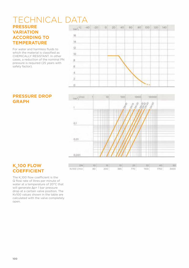
PRESSURE VARIATION ACCORDING TO TEMPERATURE
For water and harmless fluids to which the material is classified as CHEMICALLY RESISTANT. In other cases, a reduction of the nominal PN pressure is required (25 years with safety factor).
PRESSURE DROP GRAPH
KV100 FLOW
COEFFICIENT
The Kv100 flow coefficient is the
Q flow rate of litres per minute of water at a temperature of 20°C that will generate Δp= 1 bar pressure drop at a certain valve position. The Kv100 values shown in the table are calculated with the valve completely open.
DN 10 15 10 25 32 40 50
Kv100 l/min 80 200 385 770 1100 1750 3400
100
TECHNICAL DATA
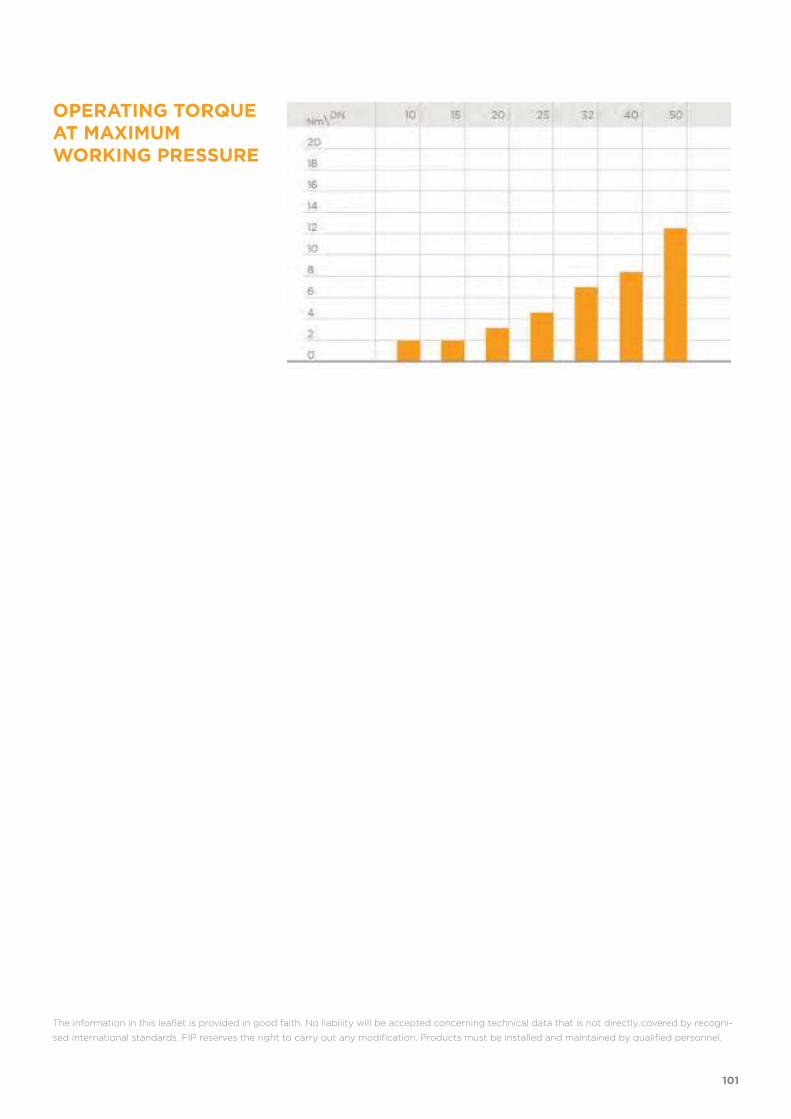
OPERATING TORQUE AT MAXIMUM WORKING PRESSURE
The information in this leaflet is provided in good faith. No liability will be accepted concerning technical data that is not directly covered by recogni-
sed international standards. FIP reserves the right to carry out any modification. Products must be installed and maintained by qualified personnel.
101

102
DIMENSIONS
VKDIMDual Block® 2-way ball valve with female ends for socket welding, metric series
d DN PN B B1
C C1
E H H1
Z g EPDM code FKM code
16 10 10 54 29 67 40 54 102 65 74,5 150 VKDIM016E VKDIM016F
20 15 10 54 29 67 40 54 102 65 73 145 VKDIM020E VKDIM020F
25 20 10 65 34,5 85 49 65 114 70 82 218 VKDIM025E VKDIM025F
32 25 10 69,5 39 85 49 73 126 78 90 298 VKDIM032E VKDIM032F
40 32 10 82,5 46 108 64 86 141 88 100 480 VKDIM040E VKDIM040F
50 40 10 89 52 108 64 98 164 93 117 682 VKDIM050E VKDIM050F
63 50 10 108 62 134 76 122 199 111 144 1166 VKDIM063E VKDIM063F
VKDIM/SHXDual Block® 2-way ball valve with handle lock and STAINLESS steel threaded inserts with female ends for socket welding, metric series
d DN PN B B1
C C1
E H H1
Z g EPDM code FKM code
16 10 10 54 29 67 40 54 102 65 74,5 160 VKDIMSHX016E VKDIMSHX016F
20 15 10 54 29 67 40 54 102 65 73 155 VKDIMSHX020E VKDIMSHX020F
25 20 10 65 34,5 85 49 65 114 70 82 228 VKDIMSHX025E VKDIMSHX025F
32 25 10 69,5 39 85 49 73 126 78 90 308 VKDIMSHX032E VKDIMSHX032F
40 32 10 82,5 46 108 64 86 141 88 100 490 VKDIMSHX040E VKDIMSHX040F
50 40 10 89 52 108 64 98 164 93 117 692 VKDIMSHX050E VKDIMSHX050F
63 50 10 108 62 134 76 122 199 111 144 1176 VKDIMSHX063E VKDIMSHX063F
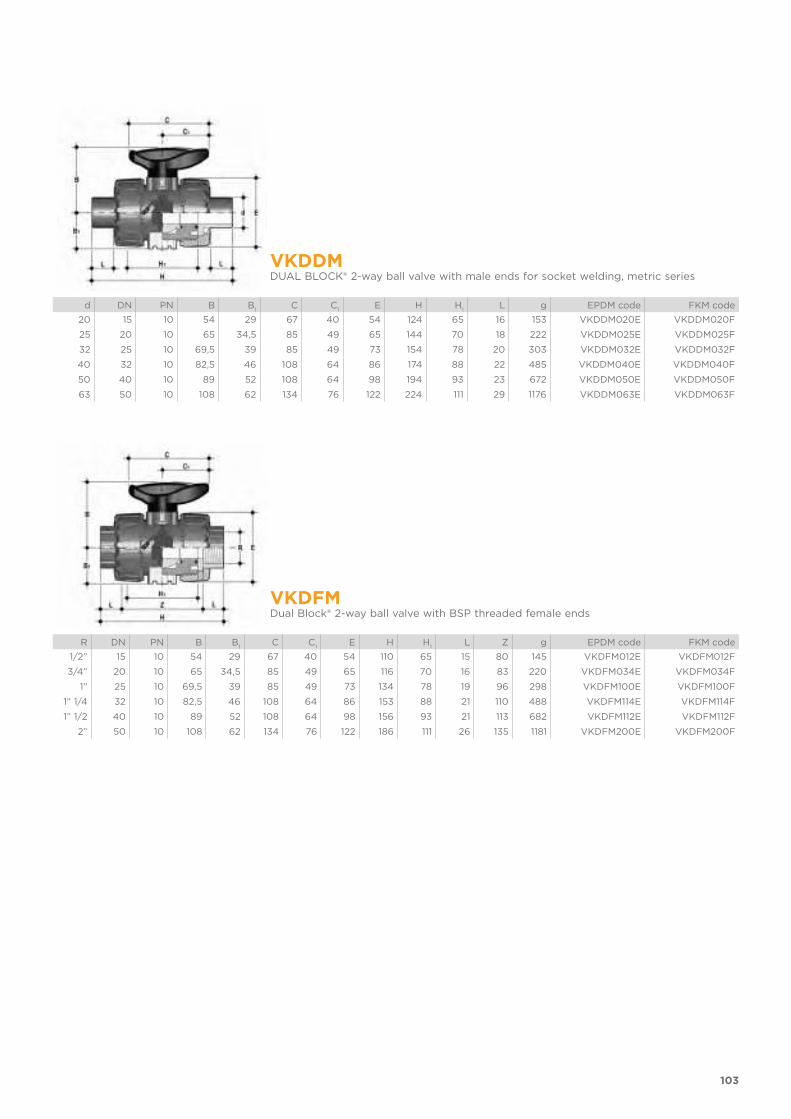
103
VKDDMDUAL BLOCK® 2-way ball valve with male ends for socket welding, metric series
d DN PN B B1
C C1
E H H1
L g EPDM code FKM code
20 15 10 54 29 67 40 54 124 65 16 153 VKDDM020E VKDDM020F
25 20 10 65 34,5 85 49 65 144 70 18 222 VKDDM025E VKDDM025F
32 25 10 69,5 39 85 49 73 154 78 20 303 VKDDM032E VKDDM032F
40 32 10 82,5 46 108 64 86 174 88 22 485 VKDDM040E VKDDM040F
50 40 10 89 52 108 64 98 194 93 23 672 VKDDM050E VKDDM050F
63 50 10 108 62 134 76 122 224 111 29 1176 VKDDM063E VKDDM063F
VKDFMDual Block® 2-way ball valve with BSP threaded female ends
R DN PN B B1
C C1
E H H1
L Z g EPDM code FKM code
1/2” 15 10 54 29 67 40 54 110 65 15 80 145 VKDFM012E VKDFM012F
3/4” 20 10 65 34,5 85 49 65 116 70 16 83 220 VKDFM034E VKDFM034F
1” 25 10 69,5 39 85 49 73 134 78 19 96 298 VKDFM100E VKDFM100F
1” 1/4 32 10 82,5 46 108 64 86 153 88 21 110 488 VKDFM114E VKDFM114F
1” 1/2 40 10 89 52 108 64 98 156 93 21 113 682 VKDFM112E VKDFM112F
2” 50 10 108 62 134 76 122 186 111 26 135 1181 VKDFM200E VKDFM200F
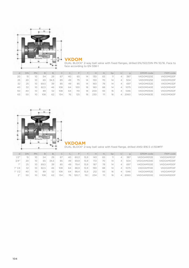
104
VKDOMDUAL BLOCK® 2-way ball valve with fixed flanges, drilled EN/ISO/DIN PN 10/16. Face to face according to EN 558-1
d DN PN B B1
C C1
F f H H1
Sp U g EPDM code FKM code
20 15 10 54 29 67 40 65 14 130 65 11 4 387 VKDOM020E VKDOM020F
25 20 10 65 34,5 85 49 75 14 150 70 14 4 504 VKDOM025E VKDOM025F
32 25 10 69,5 39 85 49 85 14 160 78 14 4 697 VKDOM032E VKDOM032F
40 32 10 82,5 46 108 64 100 18 180 88 14 4 1075 VKDOM040E VKDOM040F
50 40 10 89 52 108 64 110 18 200 93 16 4 1346 VKDOM050E VKDOM050F
63 50 10 108 62 134 76 125 18 230 111 16 4 2060 VKDOM063E VKDOM063F
VKDOAMDUAL BLOCK® 2-way ball valve with fixed flange, drilled ANSI B16.5 cl.150#FF
d DN PN B B1
C C1
F f H H1
Sp U g EPDM code FKM code
1/2” 15 10 54 29 67 40 60,3 15,9 143 65 11 4 387 VKDOAM012E VKDOAM012F
3/4” 20 10 65 34,5 85 49 69,9 15,9 172 70 14 4 504 VKDOAM034E VKDOAM034F
1” 25 10 69,5 39 85 49 79,4 15,9 187 78 14 4 697 VKDOAM100E VKDOAM100F
1” 1/4 32 10 82,5 46 108 64 88,9 15,9 190 88 14 4 1075 VKDOAM114E VKDOAM114F
1” 1/2 40 10 89 52 108 64 98,4 15,9 212 93 16 4 1346 VKDOAM112E VKDOAM112F
2” 50 10 108 62 134 76 120,7 19,1 234 111 16 4 2060 VKDOAM200E VKDOAM200F
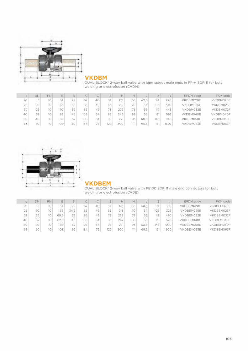
105
VKDBMDUAL BLOCK® 2-way ball valve with long spigot male ends in PP-H SDR 11 for butt welding or electrofusion (CVDM)
d DN PN B B1
C C1
E H H1
L Z g EPDM code FKM code
20 15 10 54 29 67 40 54 175 65 40,5 94 220 VKDBM020E VKDBM020F
25 20 10 65 35 85 49 65 212 70 54 106 340 VKDBM025E VKDBM025F
32 25 10 70 39 85 49 73 226 78 56 117 443 VKDBM032E VKDBM032F
40 32 10 83 46 108 64 86 246 88 56 131 593 VKDBM040E VKDBM040F
50 40 10 89 52 108 64 98 271 93 60,5 145 945 VKDBM050E VKDBM050F
63 50 10 108 62 134 76 122 300 111 65,5 161 1607 VKDBM063E VKDBM063F
VKDBEMDUAL BLOCK® 2-way ball valve with PE100 SDR 11 male end connectors for butt welding or electrofusion (CVDE)
d DN PN B B1
C C1
E H H1
L Z g EPDM code FKM code
20 15 10 54 29 67 40 54 175 65 40,5 94 210 VKDBEM020E VKDBEM020F
25 20 10 65 34,5 85 49 65 213 70 54 106 325 VKDBEM025E VKDBEM025F
32 25 10 69,5 39 85 49 73 228 78 56 117 420 VKDBEM032E VKDBEM032F
40 32 10 82,5 46 108 64 86 247 88 56 131 570 VKDBEM040E VKDBEM040F
50 40 10 89 52 108 64 98 271 93 60,5 145 900 VKDBEM050E VKDBEM050F
63 50 10 108 62 134 76 122 300 111 65,5 161 1500 VKDBEM063E VKDBEM063F

106
ACCESSORIESCVDMEnd connectors in PP-H SDR 11 PN 10, long spigot, for butt welding
d DN PN L SDR Code
20 15 10 55 11 CVDM11020
25 20 10 70 11 CVDM11025
32 25 10 74 11 CVDM11032
40 32 10 78 11 CVDM11040
50 40 10 84 11 CVDM11050
63 50 10 91 11 CVDM11063
CVDELong spigot PE100 end connectors for joints with electrofusion fittings or for butt welding
d DN PN L SDR Code
20 15 16 55 11 CVDE11020
25 20 16 70 11 CVDE11025
32 25 16 74 11 CVDE11032
40 32 16 78 11 CVDE11040
50 40 16 84 11 CVDE11050
63 50 16 91 11 CVDE11063
SHKDHandle block kit 0° - 90° lockable
d DN Code
16 - 20 10 - 15 SHKD020
25 - 32 20 - 25 SHKD032
40 - 50 32 - 40 SHKD050
63 50 SHKD063
PMKDWall mounting plate
d DN A B C C1
C2
F f f1
S Code
16 10 30 86 20 46 67,5 6,5 5,3 5,5 5 PMKD1
20 15 30 86 20 46 67,5 6,5 5,3 5,5 5 PMKD1
25 20 30 86 20 46 67,5 6,5 5,3 5,5 5 PMKD1
32 25 30 86 20 46 67,5 6,5 5,3 5,5 5 PMKD1
40 32 40 122 30 72 102 6,5 6,3 6,5 6 PMKD2
50 40 40 122 30 72 102 6,5 6,3 6,5 6 PMKD2
63 50 40 122 30 72 102 6,5 6,3 6,5 6 PMKD2
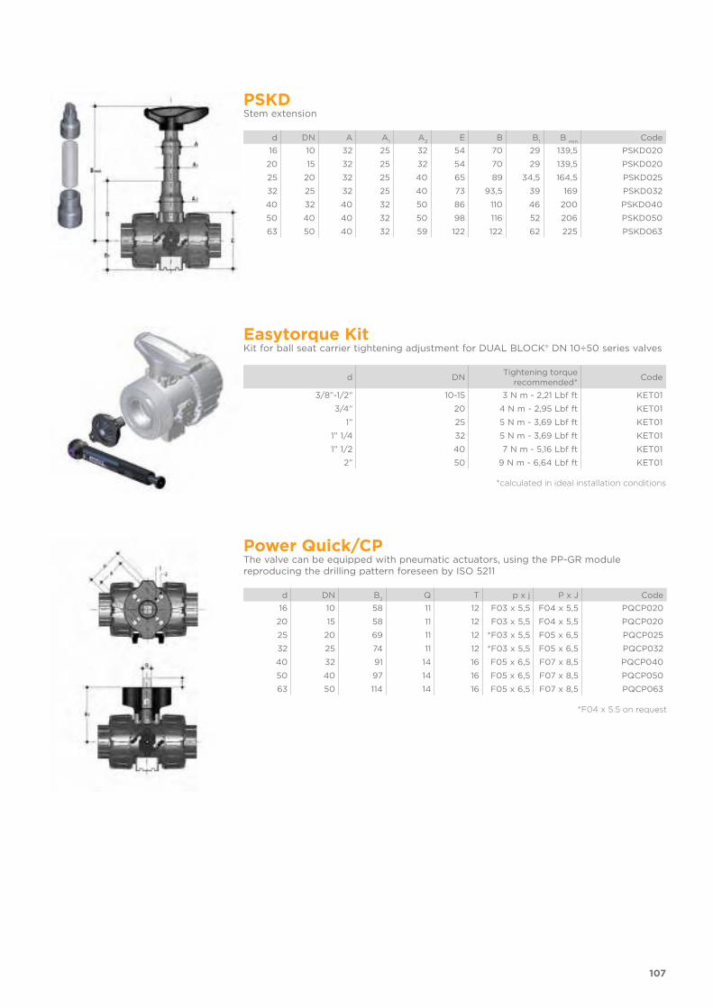
107
PSKDStem extension
d DN A A1
A2
E B B1
B min
Code
16 10 32 25 32 54 70 29 139,5 PSKD020
20 15 32 25 32 54 70 29 139,5 PSKD020
25 20 32 25 40 65 89 34,5 164,5 PSKD025
32 25 32 25 40 73 93,5 39 169 PSKD032
40 32 40 32 50 86 110 46 200 PSKD040
50 40 40 32 50 98 116 52 206 PSKD050
63 50 40 32 59 122 122 62 225 PSKD063
Easytorque KitKit for ball seat carrier tightening adjustment for DUAL BLOCK® DN 10÷50 series valves
d DNTightening torque
recommended*Code
3/8”-1/2” 10-15 3 N m - 2,21 Lbf ft KET01
3/4” 20 4 N m - 2,95 Lbf ft KET01
1” 25 5 N m - 3,69 Lbf ft KET01
1” 1/4 32 5 N m - 3,69 Lbf ft KET01
1” 1/2 40 7 N m - 5,16 Lbf ft KET01
2” 50 9 N m - 6,64 Lbf ft KET01
*calculated in ideal installation conditions
Power Quick/CPThe valve can be equipped with pneumatic actuators, using the PP-GR module reproducing the drilling pattern foreseen by ISO 5211
d DN B2
Q T p x j P x J Code
16 10 58 11 12 F03 x 5,5 F04 x 5,5 PQCP020
20 15 58 11 12 F03 x 5,5 F04 x 5,5 PQCP020
25 20 69 11 12 *F03 x 5,5 F05 x 6,5 PQCP025
32 25 74 11 12 *F03 x 5,5 F05 x 6,5 PQCP032
40 32 91 14 16 F05 x 6,5 F07 x 8,5 PQCP040
50 40 97 14 16 F05 x 6,5 F07 x 8,5 PQCP050
63 50 114 14 16 F05 x 6,5 F07 x 8,5 PQCP063
*F04 x 5.5 on request
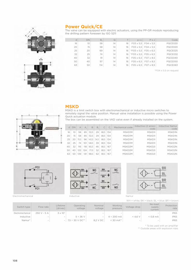
108
Power Quick/CEThe valve can be equipped with electric actuators, using the PP-GR module reproducing the drilling pattern foreseen by ISO 5211
d DN B2
Q T p x j P x J Code
16 10 58 14 16 F03 x 5,5 F04 x 5,5 PQCE020
20 15 58 14 16 F03 x 5,5 F04 x 5,5 PQCE020
25 20 69 14 16 *F03 x 5,5 F05 x 6,5 PQCE025
32 25 74 14 16 *F03 x 5,5 F05 x 6,5 PQCE032
40 32 91 14 16 F05 x 6,5 F07 x 8,5 PQCE040
50 40 97 14 16 F05 x 6,5 F07 x 8,5 PQCE050
63 50 114 14 16 F05 x 6,5 F07 x 8,5 PQCE063
*F04 x 5.5 on request
MSKDMSKD is a limit switch box with electromechanical or inductive micro switches to remotely signal the valve position. Manual valve installation is possible using the Power Quick actuation module.The box can be assembled on the VKD valve even if already installed on the system.
d DN A A1
B B1
C C1
Mechanical codeInductive (2 wires)
code Inductive Namur
code
16 10 58 85 132,5 29 88,5 134 MSKD1M MSKD1I MSKD1N
20 15 58 85 132,5 29 88,5 134 MSKD1M MSKD1I MSKD1N
25 20 70,5 96 143,5 34,5 88,5 134 MSKD1M MSKD1I MSKD1N
32 25 74 101 148,5 39 88,5 134 MSKD1M MSKD1I MSKD1N
40 32 116 118 165,5 46 88,5 167 MSKD2M MSKD2I MSKD2N
50 40 122 124 171,5 52 88,5 167 MSKD2M MSKD2I MSKD2N
63 50 139 141 188,5 62 88,5 167 MSKD2M MSKD2I MSKD2N
Electromechanical Inductive Namur
WH = white; BK = black; BL = blue; BR = brown
Switch type Flow rateLifetime[drives]
Operatingvoltage
Nominalvoltage
Workingpressure
Voltage dropNo-load
supplycurrent
Protectionrate
Electromechanical 250 V - 5 A 3 x 10⁷ - - - - - IP65
Inductive - - 5 ÷ 36 V - 4 ÷ 200 mA < 4,6 V < 0,8 mA IP65
Namur* - - 7,5 ÷ 30 V DC** 8,2 V DC < 30 mA** - - IP65
* To be used with an amplifier** Outside areas with explosion risks

All valves, whether manual or actuated, must be adequately supported in many applications. The VKD valve series is therefore provided with an inte-grated bracket that permits direct anchoring of the valve body without the need of othercomponents. For wall installation, dedicated PMKD mounting plates which are available as accessories can be used. These plates should be fastened to the valve before wall installation. PMKD plates also allow VKD valve ali-gnment with FIP ZIKM pipe clips as well as allowing different sizes of valves to be aligned.
d DN g H L J*
16 10 31,5 27 20 M4 x 6
20 15 31,5 27 20 M4 x 6
25 20 40 30 20 M4 x 6
32 25 40 30 20 M4 x 6
40 32 50 35 30 M6 x 10
50 40 50 35 30 M6 x 10
63 50 60 40 30 M6 x 10
* With threaded inserts
109
FASTENING AND SUPPORTING
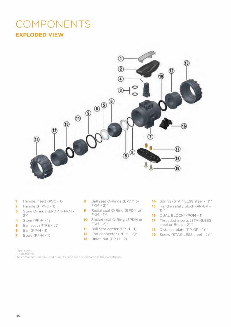
EXPLODED VIEW
1 Handle insert (PVC - 1)
2 Handle (HIPVC - 1)
3 Stem O-rings (EPDM o FKM - 2)*
4 Stem (PP-H - 1)
5 Ball seat (PTFE - 2)*
6 Ball (PP-H - 1)
7 Body (PP-H - 1)
8 Ball seat O-Rings (EPDM or FKM - 2)*
9 Radial seal O-Ring (EPDM or FKM - 1)*
10 Socket seal O-Ring (EPDM or FKM - 2)*
11 Ball seat carrier (PP-H - 1)
12 End connector (PP-H - 2)*
13 Union nut (PP-H - 2)
14 Spring (STAINLESS steel - 1)**
15 Handle safety block (PP-GR - 1)**
16 DUAL BLOCK® (POM - 1)
17 Threaded inserts (STAINLESS steel or Brass - 2)**
18 Distance plate (PP-GR - 1)**
19 Screw (STAINLESS steel - 2)**
* Spare parts** AccessoriesThe component material and quantity supplied are indicated in the parentheses.
110
COMPONENTS
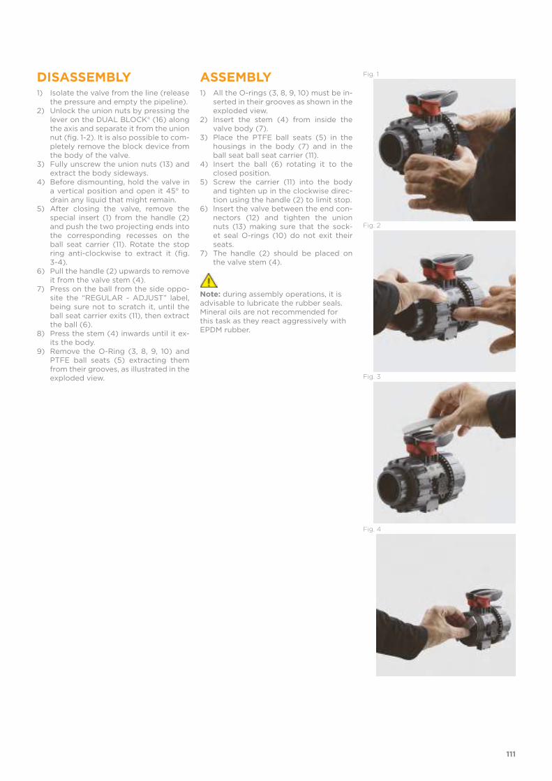
DISASSEMBLY1) Isolate the valve from the line (release
the pressure and empty the pipeline).2) Unlock the union nuts by pressing the
lever on the DUAL BLOCK® (16) along the axis and separate it from the union nut (fig. 1-2). It is also possible to com-pletely remove the block device from the body of the valve.
3) Fully unscrew the union nuts (13) and extract the body sideways.
4) Before dismounting, hold the valve in a vertical position and open it 45° to drain any liquid that might remain.
5) After closing the valve, remove the special insert (1) from the handle (2) and push the two projecting ends into the corresponding recesses on the ball seat carrier (11). Rotate the stop ring anti-clockwise to extract it (fig. 3-4).
6) Pull the handle (2) upwards to remove it from the valve stem (4).
7) Press on the ball from the side oppo-site the “REGULAR - ADJUST” label, being sure not to scratch it, until the ball seat carrier exits (11), then extract the ball (6).
8) Press the stem (4) inwards until it ex-its the body.
9) Remove the O-Ring (3, 8, 9, 10) and PTFE ball seats (5) extracting them from their grooves, as illustrated in the exploded view.
ASSEMBLY1) All the O-rings (3, 8, 9, 10) must be in-
serted in their grooves as shown in the exploded view.
2) Insert the stem (4) from inside the valve body (7).
3) Place the PTFE ball seats (5) in the housings in the body (7) and in the ball seat ball seat carrier (11).
4) Insert the ball (6) rotating it to the closed position.
5) Screw the carrier (11) into the body and tighten up in the clockwise direc-tion using the handle (2) to limit stop.
6) lnsert the valve between the end con-nectors (12) and tighten the union nuts (13) making sure that the sock-et seal O-rings (10) do not exit their seats.
7) The handle (2) should be placed on the valve stem (4).
Note: during assembly operations, it is advisable to lubricate the rubber seals. Mineral oils are not recommended for this task as they react aggressively with EPDM rubber.
Fig. 1
Fig. 2
Fig. 3
Fig. 4
111

Before proceeding with installation. please follow these instructions careful-ly:1) Check that the pipes to be connected to the valve are aligned in order to avoid mechanical stress on the threaded joints.2) Check that the DUAL BLOCK® union nut locking device (16) is fitted to the valve body.3) To release the union nuts, axially press the release lever to separate the lock and then unscrew it in the counter-clockwise direction.4) Unscrew the union nuts (13) and insert them on the pipe segments.5) Solvent weld or screw the end connectors (12) onto the pipe ends.6) Position the valve body between the end connectors and fully tighten the union nuts (13) manually by rotating clockwise without using wrenches or other tools that could damage the union nut surface.7) Lock the union nuts by returning the DUAL BLOCK® to its housing, pres-sing on it until the hinges lock on the union nuts.8) If necessary, support the pipework with FIP pipe clips or by means of the carrier built into the valve itself (see paragraph “fastening and carriers”).The VKD valve can be equipped with a handle lock to prevent ball rotation (supplied separately).When the handle safety block (14, 15) is installed, lift the lever (15) and rota-te the handle (fig. 6-7).A lock can also be installed on the handle to protect the system against tampering (fig. 8).Seal can be adjusted using the extractable insert on the handle (fig. 3-4).The seals can be adjusted later with the valve installed on the pipe by sim-ply tightening the union nuts. This "micro adjustment", only possible with FIP valves thanks to the patented "Seat stop system", allows the seal to be recovered where PTFE ball seats are worn due to a high number of opera-tions. The Easytorque kit can also be used for micro adjustments (fig. 5).
WARNINGS · If volatile liquid such as Hydrogen Peroxide (H2O2) or Sodium Hypochlo-rite (NaCIO) are used, for safety reasons we recommend you contact the service centre. These liquids, upon vaporising, could create hazardous over pressures in the area between the body and ball.· Always avoid sudden closing operations and protect the valve from acci-dental operations.
Fig.5
Fig.6
Fig.7
Fig.8
112
INSTALLATION


VKD DN 65÷100
PP-H
DUAL BLOCK® 2-way ball valve

VKD DN 65÷100
DUAL BLOCK® 2-WAY BALL VALVE
• Connection system for weld, threaded and flanged joints• Patented SEAT STOP® ball seat carrier system that lets you micro-adjust
ball seats and minimise axial force effects• Easy radial disassembly allowing quick replacement of O-rings and ball
seats without any need for tools• PN10 True Union valve body made for PP-H injection moulding equipped
with built-in bores for actuation. ISO 9393 compliant test requisites• Option of disassembling downstream pipes with the valve in the closed
position• Full bore ball with high surface finish• Integrated bracket for valve anchoring• Possibility of installing a gear box or pneumatic and/or electric actuators
by applying an ISO standard bore PP-GR flange• STAINLESS steel co-moulded stem, with square section as per ISO 5211
FIP has developed a VKD DUAL BLOCK® ball valve to introduce a high reference standard in thermosplastic valve design. VKD is a True Union ball valve that meets the most stringent needsrequired by industrial applications. This valve is also equipped with a customisable Labelling System.
Technical specifications
Construction 2-way True Union ball valve with locked carrier and union nuts
Size range DN 65 ÷ 100
Nominal pressure PN 10 with water at 20° C
Temperature range 0 °C ÷ 100 °C
Coupling standards Welding: EN ISO 15494. Can be coupled to pipes according to EN ISO 15494
Thread:ISO 228-1, DIN 2999
Flanging system: ISO 7005-1, EN ISO 1092-1, EN ISO 15494 EN 558-1, DIN 2501, ANSI B.16.5 cl.150
Reference standards Construction criteria: EN ISO 16135, EN ISO 15494
Test methods and requirements: ISO 9393
Installation criteria: DVS 2202-1, DVS 2207-11, DVS 2208-1, UNI 11318
Actuator couplings: ISO 5211
Valve material PP-H
Seal material EPDM, FKM;PTFE (ball seats)
Control options Manual control; electric actuator; pneumatic actuator
116

1 HIPVC ergonomic multifunctional handle for quick operation, lock and graduated adjustment in 10 positions. Possibility of inhibiting rotation with a lock
2 Customisable Labelling System: LCE module made of a transparent protection plug and customisable tag holder
using the LSE set (available as accessory). The customisation lets you identify the valve on the system according to specific needs
3 DUAL BLOCK® patented lock system that ensures union nut tightening hold even in severe conditions such as vibrations or heat dilation
4 Double stem with double O-Rings for ball centring and operating torque reduction
117
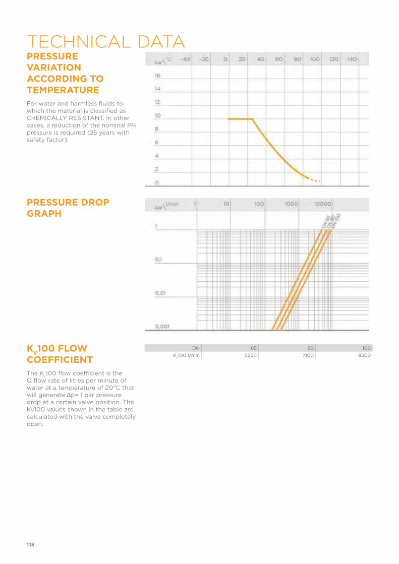
PRESSURE VARIATION ACCORDING TO TEMPERATURE
For water and harmless fluids to which the material is classified as CHEMICALLY RESISTANT. In other cases, a reduction of the nominal PN pressure is required (25 years with safety factor).
PRESSURE DROP GRAPH
KV100 FLOW
COEFFICIENT
The Kv100 flow coefficient is the
Q flow rate of litres per minute of water at a temperature of 20°C that will generate Δp= 1 bar pressure drop at a certain valve position. The Kv100 values shown in the table are calculated with the valve completely open.
DN 65 80 100
Kv100 l/min 5250 7100 9500
118
TECHNICAL DATA
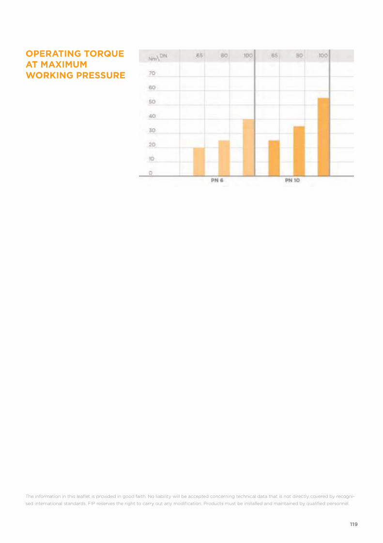
OPERATING TORQUE AT MAXIMUM WORKING PRESSURE
The information in this leaflet is provided in good faith. No liability will be accepted concerning technical data that is not directly covered by recogni-
sed international standards. FIP reserves the right to carry out any modification. Products must be installed and maintained by qualified personnel.
119
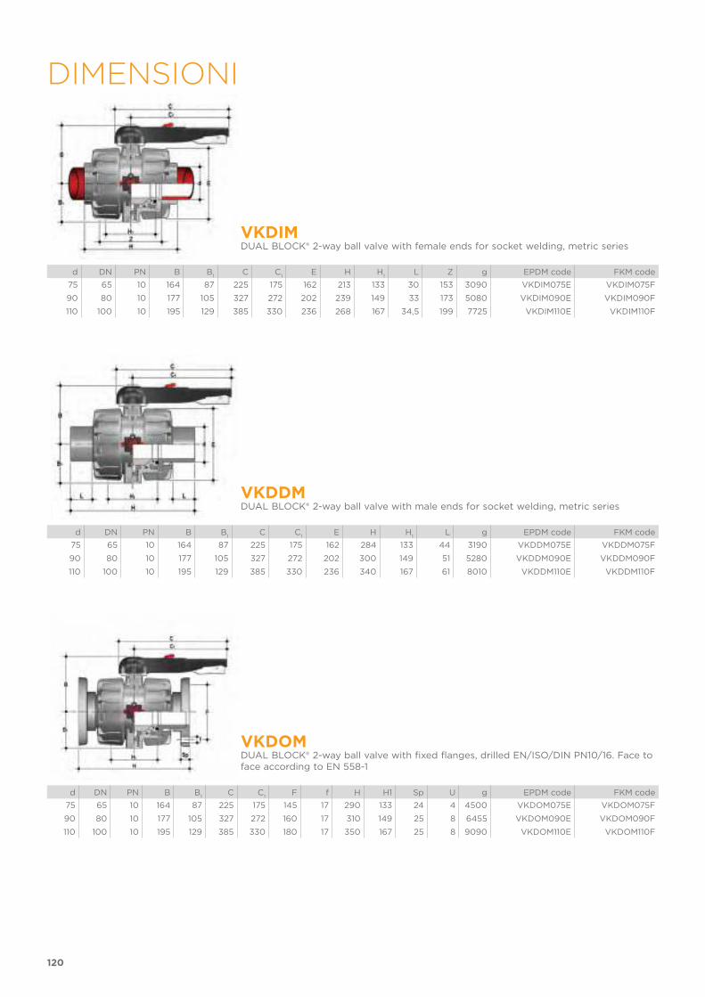
120
DIMENSIONI
VKDIMDUAL BLOCK® 2-way ball valve with female ends for socket welding, metric series
d DN PN B B1
C C1
E H H1
L Z g EPDM code FKM code
75 65 10 164 87 225 175 162 213 133 30 153 3090 VKDIM075E VKDIM075F
90 80 10 177 105 327 272 202 239 149 33 173 5080 VKDIM090E VKDIM090F
110 100 10 195 129 385 330 236 268 167 34,5 199 7725 VKDIM110E VKDIM110F
VKDDMDUAL BLOCK® 2-way ball valve with male ends for socket welding, metric series
d DN PN B B1
C C1
E H H1
L g EPDM code FKM code
75 65 10 164 87 225 175 162 284 133 44 3190 VKDDM075E VKDDM075F
90 80 10 177 105 327 272 202 300 149 51 5280 VKDDM090E VKDDM090F
110 100 10 195 129 385 330 236 340 167 61 8010 VKDDM110E VKDDM110F
VKDOMDUAL BLOCK® 2-way ball valve with fixed flanges, drilled EN/ISO/DIN PN10/16. Face to face according to EN 558-1
d DN PN B B1
C C1
F f H H1 Sp U g EPDM code FKM code
75 65 10 164 87 225 175 145 17 290 133 24 4 4500 VKDOM075E VKDOM075F
90 80 10 177 105 327 272 160 17 310 149 25 8 6455 VKDOM090E VKDOM090F
110 100 10 195 129 385 330 180 17 350 167 25 8 9090 VKDOM110E VKDOM110F

121
VKDOAMDUAL BLOCK® ball valve with ANSI B16.5 cl.150#FF fixed flanges *
d DN PN B B1
C C1
F f H H1 Sp U g EPDM code FKM code
2"1/2 65 10 164 87 225 175 145 17 290 133 24 4 4500 VKDOM075E VKDOM075F
3" 80 10 177 105 327 272 160 17 310 149 25 8 6455 VKDOM090E VKDOM090F
4" 100 10 195 129 385 330 180 17 350 167 25 8 9090 VKDOM110E VKDOM110F
VKDBMDUAL BLOCK® 2-way ball valve with long spigot male ends in PP-H SDR 11 for butt welding or electrofusion (CVDM)
d DN PN B B1
C C1
E H H1
L Z g EPDM code FKM code
75 65 10 164 87 225 175 162 356 133 71 214 3150 VKDBM075E VKDBM075F
90 80 10 177 105 327 272 202 390 149 88 214 5240 VKDBM090E VKDBM090F
110 100 10 195 129 385 330 236 431 167 92 247 7970 VKDBM110E VKDBM110F
VKDBEMDUAL BLOCK® 2-way ball valve with PE100 SDR 11 male end connectors for butt welding or electrofusion (CVDE).
d DN PN B B1
C C1
E H H1
L Z g EPDM code FKM code
75 65 10 164 87 225 175 162 356 133 71 214 3100 VKDBEM075E VKDBEM075F
90 80 10 177 105 327 272 202 390 149 88 214 5180 VKDBEM090E VKDBEM090F
110 100 10 195 129 385 330 236 431 167 92 247 7800 VKDBEM110E VKDBEM110F
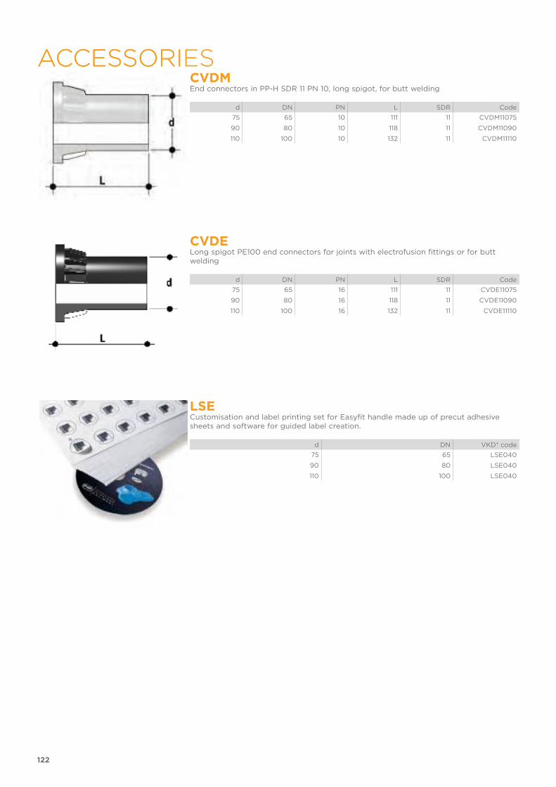
122
ACCESSORIACCESSORIESCVDMEnd connectors in PP-H SDR 11 PN 10, long spigot, for butt welding
d DN PN L SDR Code
75 65 10 111 11 CVDM11075
90 80 10 118 11 CVDM11090
110 100 10 132 11 CVDM11110
CVDELong spigot PE100 end connectors for joints with electrofusion fittings or for butt welding
d DN PN L SDR Code
75 65 16 111 11 CVDE11075
90 80 16 118 11 CVDE11090
110 100 16 132 11 CVDE11110
LSECustomisation and label printing set for Easyfit handle made up of precut adhesive sheets and software for guided label creation.
d DN VKD* code
75 65 LSE040
90 80 LSE040
110 100 LSE040

123
VKD-MSThe MS kit lets you install a limit switch valve with electromechanical or inductive micro switches on a manual VKD valve to remotely signal the valve position (open-closed). The kit can be assembled on the valve even if already installed on the system.
d DN B B1
C C1
Protection Mechanical code Inductive 3 wire
PNP codeInductive Namur*
code
75 65 266 87 150 80 IP67 FKMS1M FKMS1I FKMS1N
90 80 279 105 150 80 IP67 FKMS1M FKMS1I FKMS1N
110 100 297 129 150 80 IP67 FKMS1M FKMS1I FKMS1N
Electromechanical Inductive Namur*
* To be used with an amplifier
ACTUATOR MOUNTING FLANGEThe valve can be equipped with standard pneumatic or electric actuators and gearbox for heavy-duty operations, using a flange in PP-GR reproducing the drilling pattern provided for by standard ISO 5211 F07
d DN P x J T Q
75 65 F07 x 9 16 14
90 80 F07 x 9 16 14
110 100 F07 x 9 19 17
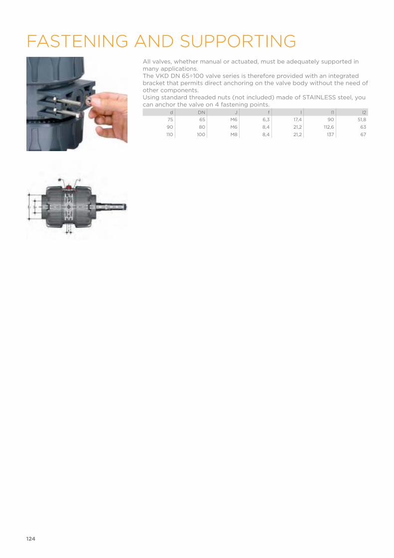
All valves, whether manual or actuated, must be adequately supported in many applications.The VKD DN 65÷100 valve series is therefore provided with an integrated bracket that permits direct anchoring on the valve body without the need of other components.Using standard threaded nuts (not included) made of STAINLESS steel, you can anchor the valve on 4 fastening points.
d DN J f l l1 l2
75 65 M6 6,3 17,4 90 51,8
90 80 M6 8,4 21,2 112,6 63
110 100 M8 8,4 21,2 137 67
124
FASTENING AND SUPPORTING
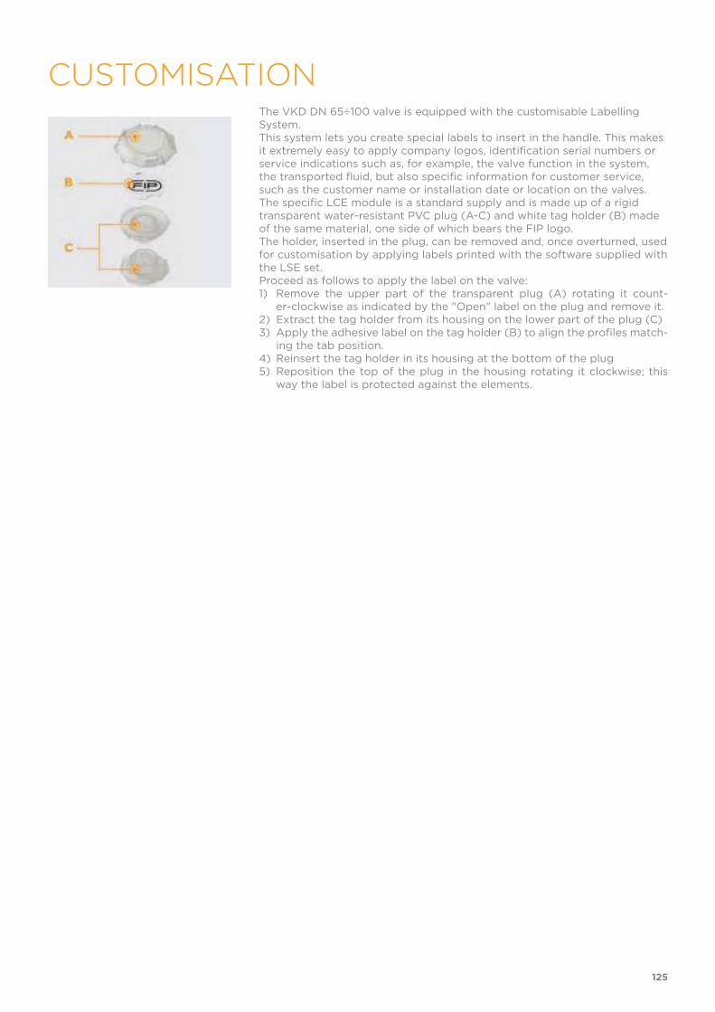
The VKD DN 65÷100 valve is equipped with the customisable Labelling System. This system lets you create special labels to insert in the handle. This makes it extremely easy to apply company logos, identification serial numbers or service indications such as, for example, the valve function in the system, the transported fluid, but also specific information for customer service, such as the customer name or installation date or location on the valves.The specific LCE module is a standard supply and is made up of a rigid transparent water-resistant PVC plug (A-C) and white tag holder (B) made of the same material, one side of which bears the FIP logo.The holder, inserted in the plug, can be removed and, once overturned, used for customisation by applying labels printed with the software supplied with the LSE set.Proceed as follows to apply the label on the valve:1) Remove the upper part of the transparent plug (A) rotating it count-
er-clockwise as indicated by the "Open" label on the plug and remove it.2) Extract the tag holder from its housing on the lower part of the plug (C)3) Apply the adhesive label on the tag holder (B) to align the profiles match-
ing the tab position.4) Reinsert the tag holder in its housing at the bottom of the plug5) Reposition the top of the plug in the housing rotating it clockwise; this
way the label is protected against the elements.
125
CUSTOMISATION
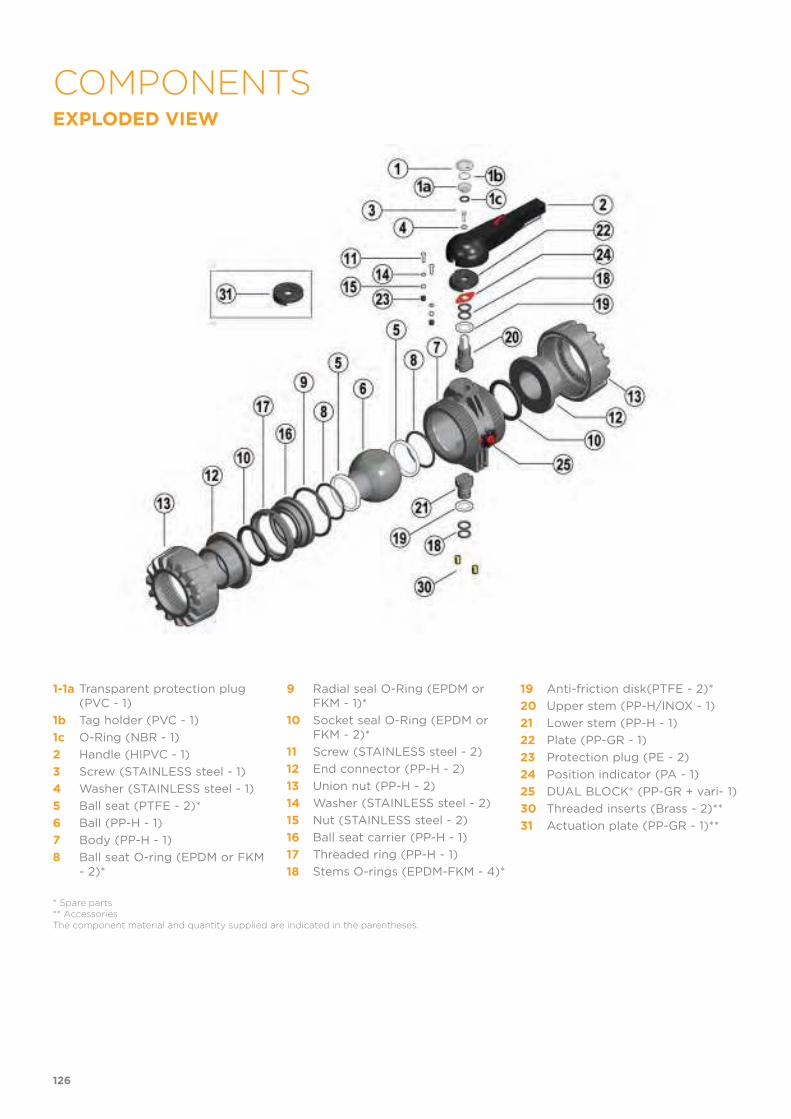
EXPLODED VIEW
1-1a Transparent protection plug (PVC - 1)
1b Tag holder (PVC - 1)
1c O-Ring (NBR - 1)
2 Handle (HIPVC - 1)
3 Screw (STAINLESS steel - 1)
4 Washer (STAINLESS steel - 1)
5 Ball seat (PTFE - 2)*
6 Ball (PP-H - 1)
7 Body (PP-H - 1)
8 Ball seat O-ring (EPDM or FKM - 2)*
9 Radial seal O-Ring (EPDM or FKM - 1)*
10 Socket seal O-Ring (EPDM or FKM - 2)*
11 Screw (STAINLESS steel - 2)
12 End connector (PP-H - 2)
13 Union nut (PP-H - 2)
14 Washer (STAINLESS steel - 2)
15 Nut (STAINLESS steel - 2)
16 Ball seat carrier (PP-H - 1)
17 Threaded ring (PP-H - 1)
18 Stems O-rings (EPDM-FKM - 4)*
19 Anti-friction disk(PTFE - 2)*
20 Upper stem (PP-H/INOX - 1)
21 Lower stem (PP-H - 1)
22 Plate (PP-GR - 1)
23 Protection plug (PE - 2)
24 Position indicator (PA - 1)
25 DUAL BLOCK® (PP-GR + vari- 1)
30 Threaded inserts (Brass - 2)**
31 Actuation plate (PP-GR - 1)**
* Spare parts** AccessoriesThe component material and quantity supplied are indicated in the parentheses.
126
COMPONENTS

DISASSEMBLY1) Isolate the valve from the line (release
the pressure and empty the pipeline).2) Release the union nuts by rotating the
button (25) to the left, pointing the ar-row on the open lock (fig. 1).
3) Unscrew the union nuts (13) and ex-tract the body (7) (fig. 2).
4) Before dismounting, hold the valve in a vertical position and open it 45° to drain any liquid that might remain.
5) Open the valve.6) Remove the protection plug on the
handle (2) and unscrew the screw (3) with the washer (4).
7) Remove the handle (2).8) Remove the screws (11) and plate (22)
from the body (7).9) Insert the two supplied wrench protru-
sions in the corresponding apertures on the threaded ring (17), extracting it by rotating counterclockwise with the ball seat carrier (16) (fig. 3).
10) Press on the ball (6), being careful not to scratch it, and remove it from the body.
11) Press the upper stem (20) inwards and extract it from the body and re-move the lower stem (21). Remove the anti-friction disks (19).
12) Remove the O-Ring (8, 9, 10, 18) and PTFE ball seats (5) extracting them from their housings, as illustrated in the exploded view.
ASSEMBLY1) All the O-rings (8, 9, 10, 18) must be
inserted in their grooves as shown in the exploded view.
2) Place the anti-friction disks (19) on the stems (20-21) and insert the stems in their housings in the body.
3) Place the PTFE ball seats (5) in the housings in the valve body (7) and in the carrier (16).
4) Insert the ball (6) rotating it to the closed position.
5) Insert the carrier with threaded ring (17) into the body and tighten up in the clockwise direction using the sup-plied tool, to limit stop.
6) Position the plate (22) with rack on the body, and screw in the screws (11) washers (14) and nuts (15).
7) The handle (2) with protection plug (1, 1a, 1b, 1c) should be placed on the stem (20) (fig. 4).
8) Screw in the screw (3) with the wash-er (4) and position the protection plug (1, 1a, 1b, 1c).
9) Insert the valve between the end con-nectors (12) and tighten the union nuts (13), making sure that the sock-et seal O-rings (10) do not exit their seats.
10) Release the union nuts by rotating the button (25) to the right, pointing the arrow on the closed lock (fig. 1).
Note: during assembly operations, it is advisable to lubricate the rubber seals. Mineral oils are not recommended for this task as they react aggressively with EPDM rubber.
Fig.1
Fig.2
Fig.3
Fig.4
127

Before proceeding with installation. please follow these instructions careful-ly:1) Check that the pipes to be connected to the valve are aligned in order to avoid mechanical stress on the threaded joints.2) Make sure the DUAL BLOCK® union nut lock system (25) is in the FREE position.3) Unscrew the union nuts (13) and insert them on the pipe segments.4) Solvent weld or screw the end connectors (12) onto the pipe ends.5) Position the valve body between the end connectors and fully tighten the union nuts (13) clockwise with an appropriate wrench.6) Lock the union nuts rotating the button (25) clockwise (see paragraph "union nut lock").7) If necessary, support the piping with FIP pipe clips or by means of the carrier built into the valve itself (see paragraph “fastening and supporting”).Adjust the ball seat carriers using the supplied tool (fig. 3).The seals can be installed later with the valve installed on the pipe by simply tightening the union nuts. This "micro adjustment", only possible with FIP valves thanks to the patented "Seat stop system", allows the seal to be reco-vered where PTFE ball seats are worn due to a high number of operations.
UNION NUT LOCK
Rotate the button to the left, pointing the arrow on the open lock to un-lock DUAL BLOCK®: the valve union nuts are free to rotate clockwise and counter-clockwise. Rotate the button to the right, pointing the arrow on the closed lock to lock DUAL BLOCK®: the valve union nuts are blocked in the desired position.
HANDLE LOCK
Thanks to the multifunctional handle and the red manoeuvre button on the lever, you can perform a 0°-90° operation and a graduated operation by means of the 10 intermediate positions and a stop lock: the handle can be locked in each of the 10 positions by simply pressing the Free-lock button. A lock can also be installed on the handle to protect the system against tampering.The valve is two-way and can be installed in any position. It can also be installed at end line or tank.
WARNINGS If volatile liquid such as Hydrogen Peroxide (H2O2) or Sodium Hypochlorite (NaCIO) are used, for safety reasons we recommend you contact the service centre. These liquids, upon vaporising, could create hazardous over pressu-res in the area between the body and ball.Always avoid sudden closing operations and protect the valve from acci-dental operations.
128
INSTALLATION


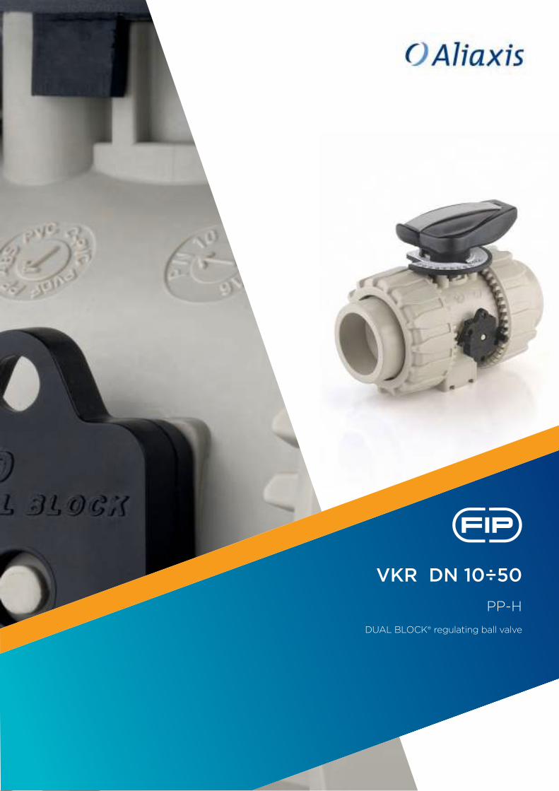
VKR DN 10÷50
PP-H
DUAL BLOCK® regulating ball valve

VKR DN 10÷50
DUAL BLOCK® REGULATING BALL VALVE
• Connection system for weld, threaded and flanged joints• Patented SEAT STOP® ball seat carrier system that lets you micro-adjust
ball seats and minimise axial force effects• Easy radial disassembly allowing quick replacement of O-rings and ball
seats without any need for tools• PN10 True Union valve body made for PP-H injection moulding equipped
with built-in bores for actuation. ISO 9393 compliant test requisites• Option of disassembling downstream pipes with the valve in the closed
position• High surface finish stem with double O-Ring and double groove ball con-
nection• Integrated bracket for valve anchoring• Ball seat carrier can be adjusted using the Easytorque adjustment kit• Actuation option: version with electric modulating actuator with 4-20 mA
/0-10 V inlet and 4-20 mA / 0-10 V outlet to monitor the position• Valve suitable for carrying fluids that are clean and free of suspended
particles
The VKR DUAL BLOCK® valve combines high reliability and safety aspects typical of VKD full bore ball valves with the new flow adjustment function with typical linear curve that meets the most stringent needs typical of industrial applications.
Technical specifications
Construction 2-way True Union regulating ball valve with locked carrier and lockable union nuts
Size range DN 10 ÷ 50
Nominal pressure PN 10 con acqua a 20 °C
Temperature range 0 °C ÷ 100 °C
Coupling standards Welding: EN ISO 15494 Can be coupled to pipes according to EN ISO 15494
Thread: ISO 228-1, DIN 2999
Flanging system: ISO 7005-1, EN ISO 1092-1, EN ISO 15494, EN 558-1, DIN 2501, ANSI B.16.5 cl. 150
Reference standards Construction criteria: EN ISO 16135, EN ISO 15494
Test methods and requirements: ISO 9393
Installation criteria: DVS 2202-1, DVS 2207-11, DVS 2208-1, UNI 11318
Actuator couplings: ISO 5211
Valve material PP-H
Seal material EPDM, FKM (standard size O-Rings);PTFE (ball seats)
Control options Manual control; electric actuator
132
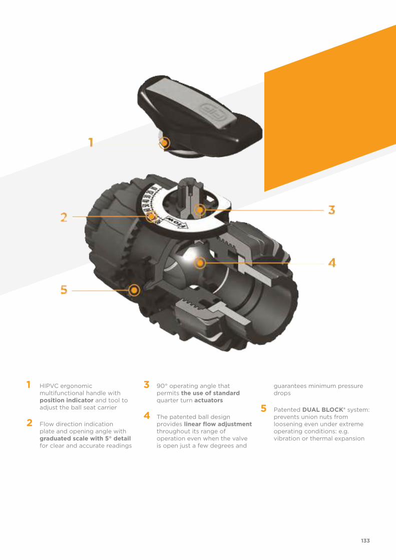
1 HIPVC ergonomic multifunctional handle with position indicator and tool to adjust the ball seat carrier
2 Flow direction indication plate and opening angle with graduated scale with 5° detail for clear and accurate readings
3 90° operating angle that permits the use of standard quarter turn actuators
4 The patented ball design provides linear flow adjustment throughout its range of operation even when the valve is open just a few degrees and
guarantees minimum pressure drops
5 Patented DUAL BLOCK® system: prevents union nuts from loosening even under extreme operating conditions: e.g. vibration or thermal expansion
133
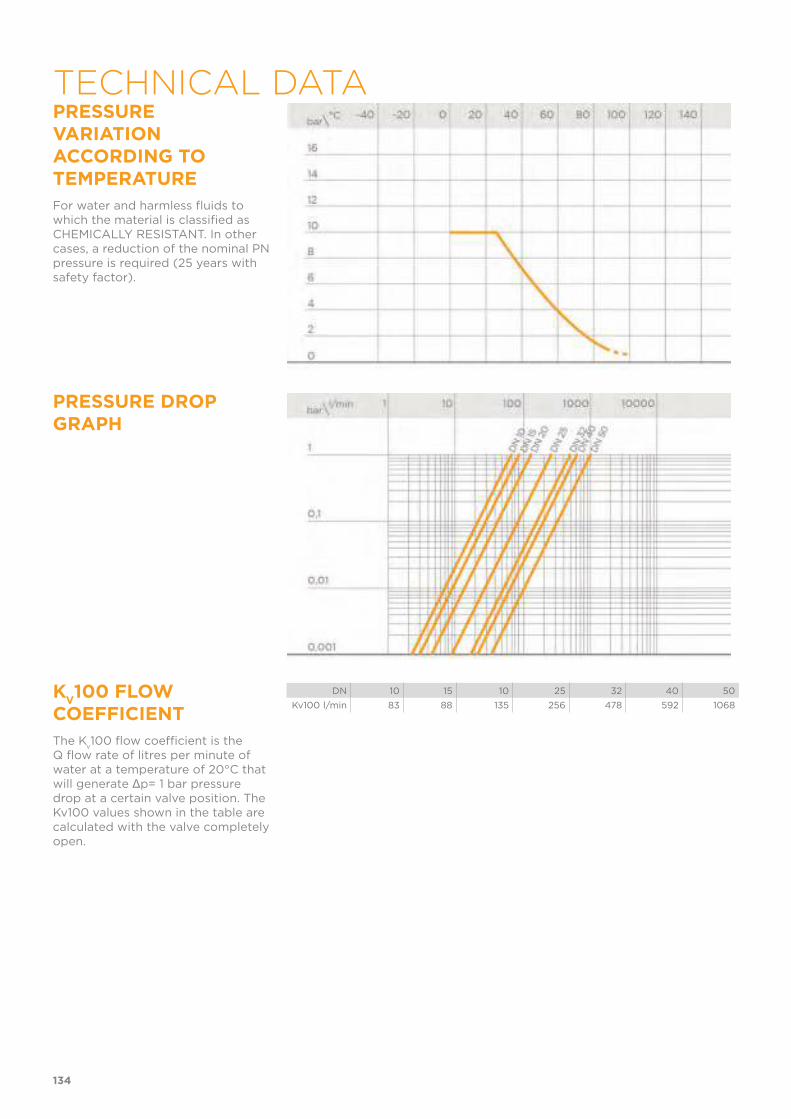
PRESSURE VARIATION ACCORDING TO TEMPERATURE
For water and harmless fluids to which the material is classified as CHEMICALLY RESISTANT. In other cases, a reduction of the nominal PN pressure is required (25 years with safety factor).
PRESSURE DROP GRAPH
KV100 FLOW
COEFFICIENT
The Kv100 flow coefficient is the
Q flow rate of litres per minute of water at a temperature of 20°C that will generate Δp= 1 bar pressure drop at a certain valve position. The Kv100 values shown in the table are calculated with the valve completely open.
DN 10 15 10 25 32 40 50
Kv100 l/min 83 88 135 256 478 592 1068
134
TECHNICAL DATA
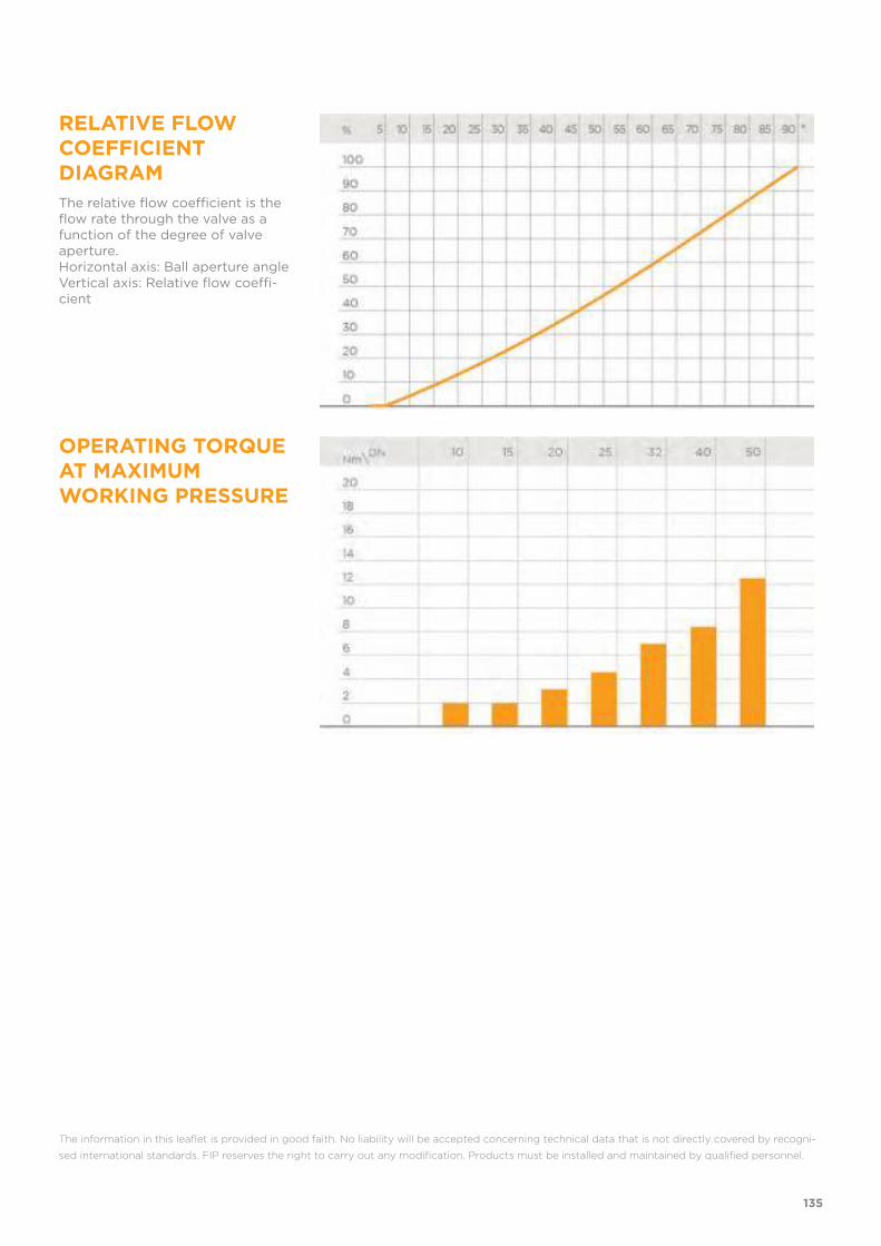
RELATIVE FLOW COEFFICIENT DIAGRAM
The relative flow coefficient is the flow rate through the valve as a function of the degree of valve aperture.Horizontal axis: Ball aperture angle Vertical axis: Relative flow coeffi-cient
OPERATING TORQUE AT MAXIMUM WORKING PRESSURE
The information in this leaflet is provided in good faith. No liability will be accepted concerning technical data that is not directly covered by recogni-
sed international standards. FIP reserves the right to carry out any modification. Products must be installed and maintained by qualified personnel.
135
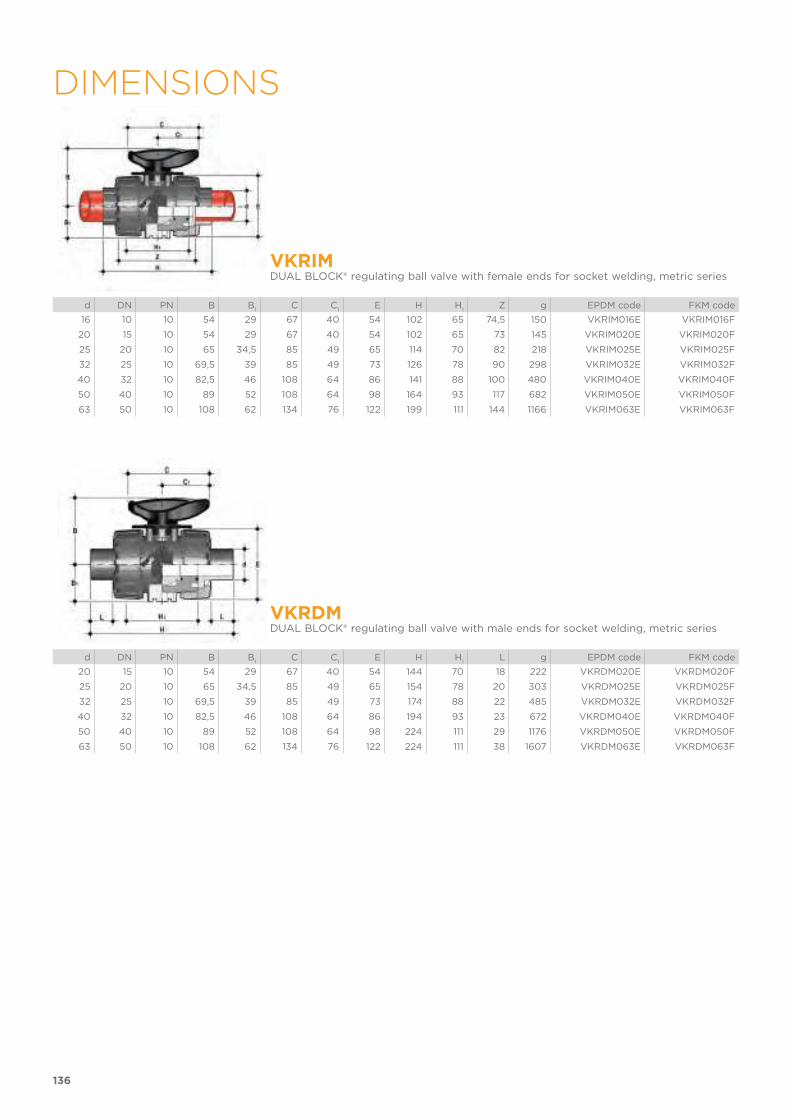
136
DIMENSIONS
VKRIMDUAL BLOCK® regulating ball valve with female ends for socket welding, metric series
d DN PN B B1
C C1
E H H1
Z g EPDM code FKM code
16 10 10 54 29 67 40 54 102 65 74,5 150 VKRIM016E VKRIM016F
20 15 10 54 29 67 40 54 102 65 73 145 VKRIM020E VKRIM020F
25 20 10 65 34,5 85 49 65 114 70 82 218 VKRIM025E VKRIM025F
32 25 10 69,5 39 85 49 73 126 78 90 298 VKRIM032E VKRIM032F
40 32 10 82,5 46 108 64 86 141 88 100 480 VKRIM040E VKRIM040F
50 40 10 89 52 108 64 98 164 93 117 682 VKRIM050E VKRIM050F
63 50 10 108 62 134 76 122 199 111 144 1166 VKRIM063E VKRIM063F
VKRDMDUAL BLOCK® regulating ball valve with male ends for socket welding, metric series
d DN PN B B1
C C1
E H H1
L g EPDM code FKM code
20 15 10 54 29 67 40 54 144 70 18 222 VKRDM020E VKRDM020F
25 20 10 65 34,5 85 49 65 154 78 20 303 VKRDM025E VKRDM025F
32 25 10 69,5 39 85 49 73 174 88 22 485 VKRDM032E VKRDM032F
40 32 10 82,5 46 108 64 86 194 93 23 672 VKRDM040E VKRDM040F
50 40 10 89 52 108 64 98 224 111 29 1176 VKRDM050E VKRDM050F
63 50 10 108 62 134 76 122 224 111 38 1607 VKRDM063E VKRDM063F
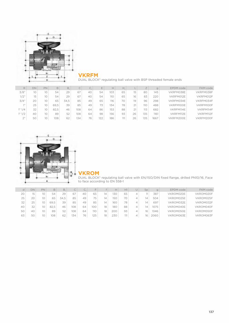
137
VKRFMDUAL BLOCK® regulating ball valve with BSP threaded female ends
R DN PN B B1
C C1
E H H1
L Z g EPDM code FKM code
3/8” 10 10 54 29 67 40 54 103 65 15 80 145 VKRFM038E VKRFM038F
1/2” 15 10 54 29 67 40 54 110 65 16 83 220 VKRFM012E VKRFM012F
3/4” 20 10 65 34,5 85 49 65 116 70 19 96 298 VKRFM034E VKRFM034F
1” 25 10 69,5 39 85 49 73 134 78 21 110 488 VKRFM100E VKRFM100F
1” 1/4 32 10 82,5 46 108 64 86 153 88 21 113 682 VKRFM114E VKRFM114F
1” 1/2 40 10 89 52 108 64 98 156 93 26 135 1161 VKRFM112E VKRFM112F
2” 50 10 108 62 134 76 122 186 111 26 135 1667 VKRFM200E VKRFM200F
VKROMDUAL BLOCK® regulating ball valve with EN/ISO/DIN fixed flange, drilled PN10/16. Face to face according to EN 558-1
d DN PN B B1
C C1
F f H H1 U Sp g EPDM code FKM code
20 15 10 54 29 67 40 65 14 130 65 4 11 387 VKROM020E VKROM020F
25 20 10 65 34,5 85 49 75 14 150 70 4 14 504 VKROM025E VKROM025F
32 25 10 69,5 39 85 49 85 14 160 78 4 14 697 VKROM032E VKROM032F
40 32 10 82,5 46 108 64 100 18 180 88 4 14 1075 VKROM040E VKROM040F
50 40 10 89 52 108 64 110 18 200 93 4 16 1346 VKROM050E VKROM050F
63 50 10 108 62 134 76 125 18 230 111 4 16 2060 VKROM063E VKROM063F
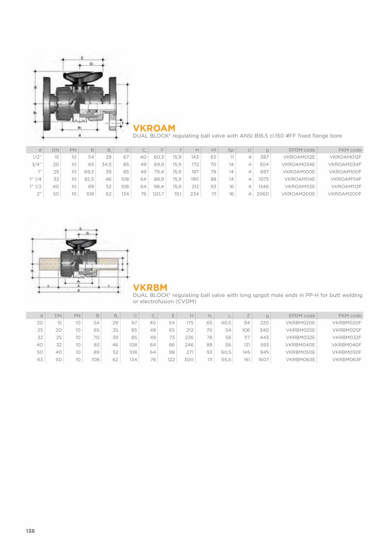
138
VKROAMDUAL BLOCK® regulating ball valve with ANSI B16.5 cl.150 #FF fixed flange bore
d DN PN B B1
C C1
F f H H1 Sp U g EPDM code FKM code
1/2” 15 10 54 29 67 40 60,3 15,9 143 65 11 4 387 VKROAM012E VKROAM012F
3/4” 20 10 65 34,5 85 49 69,9 15,9 172 70 14 4 504 VKROAM034E VKROAM034F
1” 25 10 69,5 39 85 49 79,4 15,9 187 78 14 4 697 VKROAM100E VKROAM100F
1” 1/4 32 10 82,5 46 108 64 88,9 15,9 190 88 14 4 1075 VKROAM114E VKROAM114F
1” 1/2 40 10 89 52 108 64 98,4 15,9 212 93 16 4 1346 VKROAM112E VKROAM112F
2” 50 10 108 62 134 76 120,7 19,1 234 111 16 4 2060 VKROAM200E VKROAM200F
VKRBMDUAL BLOCK® regulating ball valve with long spigot male ends in PP-H for butt welding or electrofusion (CVDM)
d DN PN B B1
C C1
E H H1
L Z g EPDM code FKM code
20 15 10 54 29 67 40 54 175 65 40,5 94 220 VKRBM020E VKRBM020F
25 20 10 65 35 85 49 65 212 70 54 106 340 VKRBM025E VKRBM025F
32 25 10 70 39 85 49 73 226 78 56 117 443 VKRBM032E VKRBM032F
40 32 10 83 46 108 64 86 246 88 56 131 593 VKRBM040E VKRBM040F
50 40 10 89 52 108 64 98 271 93 60,5 145 945 VKRBM050E VKRBM050F
63 50 10 108 62 134 76 122 300 111 65,5 161 1607 VKRBM063E VKRBM063F
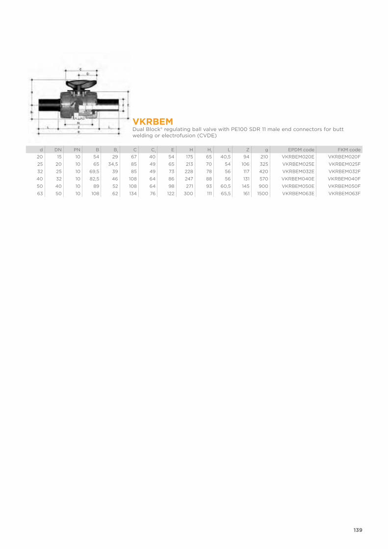
139
VKRBEMDual Block® regulating ball valve with PE100 SDR 11 male end connectors for butt welding or electrofusion (CVDE)
d DN PN B B1
C C1
E H H1
L Z g EPDM code FKM code
20 15 10 54 29 67 40 54 175 65 40,5 94 210 VKRBEM020E VKRBEM020F
25 20 10 65 34,5 85 49 65 213 70 54 106 325 VKRBEM025E VKRBEM025F
32 25 10 69,5 39 85 49 73 228 78 56 117 420 VKRBEM032E VKRBEM032F
40 32 10 82,5 46 108 64 86 247 88 56 131 570 VKRBEM040E VKRBEM040F
50 40 10 89 52 108 64 98 271 93 60,5 145 900 VKRBEM050E VKRBEM050F
63 50 10 108 62 134 76 122 300 111 65,5 161 1500 VKRBEM063E VKRBEM063F

140
ACCESSORIACCESSORIESCVDMEnd connectors in PP-H SDR 11 PN 10, long spigot, for butt welding
d DN PN L SDR Code
20 15 10 55 11 CVDM11020
25 20 10 70 11 CVDM11025
32 25 10 74 11 CVDM11032
40 32 10 78 11 CVDM11040
50 40 10 84 11 CVDM11050
63 50 10 91 11 CVDM11063
CVDELong spigot PE100 end connectors for joints with electrofusion fittings or for butt welding
d DN PN L SDR Code
20 15 16 55 11 CVDE11020
25 20 16 70 11 CVDE11025
32 25 16 74 11 CVDE11032
40 32 16 78 11 CVDE11040
50 40 16 84 11 CVDE11050
63 50 16 91 11 CVDE11063
PMKDWall mounting plate
d DN A B C C1
C2
F f f1
S Code
16 10 30 86 20 46 67,5 6,5 5,3 5,5 5 PMKD1
20 15 30 86 20 46 67,5 6,5 5,3 5,5 5 PMKD1
25 20 30 86 20 46 67,5 6,5 5,3 5,5 5 PMKD1
32 25 30 86 20 46 67,5 6,5 5,3 5,5 5 PMKD1
40 32 40 122 30 72 102 6,5 6,3 6,5 6 PMKD2
50 40 40 122 30 72 102 6,5 6,3 6,5 6 PMKD2
63 50 40 122 30 72 102 6,5 6,3 6,5 6 PMKD2
Easytorque KitKit for ball seat carrier tightening adjustment for DUAL BLOCK® DN 10÷50 series valves
d DNTightening torque
recommended*Code
3/8”-1/2” 10-15 3 N m - 2,21 Lbf ft KET01
3/4” 20 4 N m - 2,95 Lbf ft KET01
1” 25 5 N m - 3,69 Lbf ft KET01
1” 1/4 32 5 N m - 3,69 Lbf ft KET01
1” 1/2 40 7 N m - 5,16 Lbf ft KET01
2” 50 9 N m - 6,64 Lbf ft KET01
*calculated in ideal installation conditions

All valves, whether manual or driven, must be adequately supported in many applications.The VKR valve series is therefore provided with an integrated bracket that permits direct anchoring of the valve body without the need of other com-ponents.For wall installation, dedicated PMKD mounting plates which are available as accessories can be used. These plates should be fastened to the valve before wall installation.PMKD plates also allow VKR valve alignment with FIP ZIKM pipe clips as well as allowing different sizes of valves to be aligned.
d DN g H L J*
16 10 31,5 27 20 M4 x 6
20 15 31,5 27 20 M4 x 6
25 20 40 30 20 M4 x 6
32 25 40 30 20 M4 x 6
40 32 50 35 30 M6 x 10
50 40 50 35 30 M6 x 10
63 50 60 40 30 M6 x 10
* With threaded inserts
141
FASTENING AND SUPPORTING

EXPLODED VIEW
1 Handle insert (PVC - 1)
2 Handle (HIPVC - 1)
3 Stem O-ring (EPDM or FKM - 2)*
4 Stem (PP-H - 1)
5 Ball seat (PTFE - 2)*
6 Patented ball design (PP-H - 1)
7 Body (PP-H - 1)
8 Ball seat O-Rings (EPDM or FKM - 2)*
9 Radial seal O-Ring (EPDM or FKM - 1)*
10 Socket seal O-Ring (EPDM or FKM - 2)*
11 Ball seat carrier (PP-H - 1)
12 End connector (PP-H - 2)*
13 Union nut (PP-H - 2)
16 DUAL BLOCK® (POM - 1)
17 Threaded inserts (STAINLESS steel or Brass - 2)**
18 Distance plate (PP-GR - 1)**
19 Screw (STAINLESS steel - 2)**
28 Graduated plate (POM-PVC - 1)
29 Indicator (PVC - 1)
* Spare parts** AccessoriesThe component material and quantity supplied are indicated in the parentheses.
142
COMPONENTS
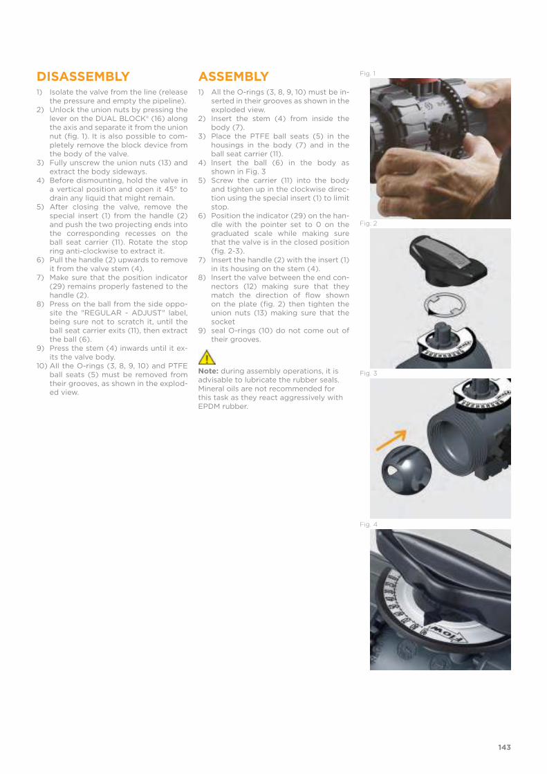
DISASSEMBLY1) Isolate the valve from the line (release
the pressure and empty the pipeline).2) Unlock the union nuts by pressing the
lever on the DUAL BLOCK® (16) along the axis and separate it from the union nut (fig. 1). It is also possible to com-pletely remove the block device from the body of the valve.
3) Fully unscrew the union nuts (13) and extract the body sideways.
4) Before dismounting, hold the valve in a vertical position and open it 45° to drain any liquid that might remain.
5) After closing the valve, remove the special insert (1) from the handle (2) and push the two projecting ends into the corresponding recesses on the ball seat carrier (11). Rotate the stop ring anti-clockwise to extract it.
6) Pull the handle (2) upwards to remove it from the valve stem (4).
7) Make sure that the position indicator (29) remains properly fastened to the handle (2).
8) Press on the ball from the side oppo-site the "REGULAR - ADJUST" label, being sure not to scratch it, until the ball seat carrier exits (11), then extract the ball (6).
9) Press the stem (4) inwards until it ex-its the valve body.
10) All the O-rings (3, 8, 9, 10) and PTFE ball seats (5) must be removed from their grooves, as shown in the explod-ed view.
ASSEMBLY1) All the O-rings (3, 8, 9, 10) must be in-
serted in their grooves as shown in the exploded view.
2) Insert the stem (4) from inside the body (7).
3) Place the PTFE ball seats (5) in the housings in the body (7) and in the ball seat carrier (11).
4) lnsert the ball (6) in the body as shown in Fig. 3
5) Screw the carrier (11) into the body and tighten up in the clockwise direc-tion using the special insert (1) to limit stop.
6) Position the indicator (29) on the han-dle with the pointer set to 0 on the graduated scale while making sure that the valve is in the closed position (fig. 2-3).
7) Insert the handle (2) with the insert (1) in its housing on the stem (4).
8) lnsert the valve between the end con-nectors (12) making sure that they match the direction of flow shown on the plate (fig. 2) then tighten the union nuts (13) making sure that the socket
9) seal O-rings (10) do not come out of their grooves.
Note: during assembly operations, it is advisable to lubricate the rubber seals. Mineral oils are not recommended for this task as they react aggressively with EPDM rubber.
Fig. 1
Fig. 2
Fig. 3
Fig. 4
143
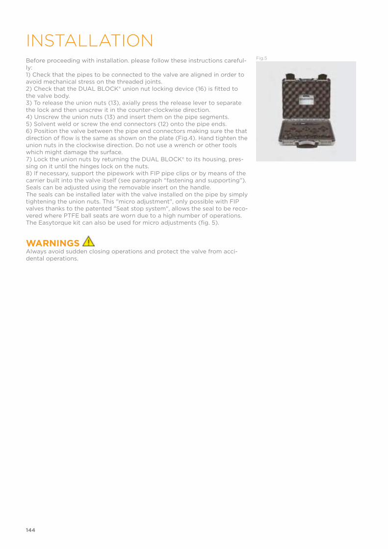
Before proceeding with installation. please follow these instructions careful-ly:1) Check that the pipes to be connected to the valve are aligned in order to avoid mechanical stress on the threaded joints.2) Check that the DUAL BLOCK® union nut locking device (16) is fitted to the valve body.3) To release the union nuts (13), axially press the release lever to separate the lock and then unscrew it in the counter-clockwise direction.4) Unscrew the union nuts (13) and insert them on the pipe segments.5) Solvent weld or screw the end connectors (12) onto the pipe ends.6) Position the valve between the pipe end connectors making sure the that direction of flow is the same as shown on the plate (Fig.4). Hand tighten the union nuts in the clockwise direction. Do not use a wrench or other tools which might damage the surface.7) Lock the union nuts by returning the DUAL BLOCK® to its housing, pres-sing on it until the hinges lock on the nuts.8) If necessary, support the pipework with FIP pipe clips or by means of the carrier built into the valve itself (see paragraph “fastening and supporting”).Seals can be adjusted using the removable insert on the handle.The seals can be installed later with the valve installed on the pipe by simply tightening the union nuts. This "micro adjustment", only possible with FIP valves thanks to the patented "Seat stop system", allows the seal to be reco-vered where PTFE ball seats are worn due to a high number of operations.The Easytorque kit can also be used for micro adjustments (fig. 5).
WARNINGS Always avoid sudden closing operations and protect the valve from acci-dental operations.
Fig.5
144
INSTALLATION


TKD DN 15÷50
PP-H
DUAL BLOCK® 3-way ball valve

TKD DN 15÷50
DUAL BLOCK® 3-WAY BALL VALVE
• Connection system for weld and threaded joints• Patented SEAT STOP® ball seat carrier system that lets you micro-adjust
ball seats and minimise axial force effects• Easy radial disassembly allowing quick replacement of O-rings and ball
seats without any need for tools• PN10 True Union valve body made for PP-H injection moulding equipped
with built-in bores for actuation. ISO 9393 compliant test requisites• Option of disassembling downstream pipes with the valve in the closed
position• High surface finish stem with double O-Ring and double groove ball
connection, equipped with optical position indicator for correct handle installation
• Integrated bracket for valve anchoring• Possibility of installing pneumatic and/or electric actuators thanks to the
robust integrated bracket for valve anchoring for easy and quick automa-tion using the Power Quick module (optional)
FIP has developed a TKD DUAL BLOCK® ball valve to introduce a high reference standard in thermosplastic valve design. TKD is a True Union diverting and mixing ball valve that meets the most stringent needs required in industrial applications. Technical specifications
Construction 3-way True Union ball valve with locked carrier and lockable union nuts
Size range DN 15 ÷ 50
Nominal pressure PN 10 with water at 20° C
Temperature range 0 °C ÷ 100 °C
Coupling standards Welding: EN ISO 15494 Can be coupled to pipes according to EN ISO 15494
Thread: ISO 228-1, DIN 2999
Reference standards Construction criteria: EN ISO 16135, EN ISO 15494
Test methods and requirements: ISO 9393
Installation criteria: DVS 2202-1, DVS 2207-11, DVS 2208-1, UNI 11318
Actuator couplings: ISO 5211
Valve material PP-H
Seal material EPDM, FKM (standard size O-Rings);PTFE (ball seats)
Control options Manual control; electric actuator; pneumatic actuator
148

1 Ergonomic HIPVC handle equipped with removable tool to adjust the ball seat carrier. Possibility of installing the LTKD stroke limiter (available as an accessory) that permits ball and handle rotation only for set opening and closing angles at 90° or 180°
2 Handle lock 0°- 90° SHKD (available as an accessory) ergonomically operable during service and padlockable
3 DUAL BLOCK® patented lock system that ensures union nut tightening hold even in severe conditions such as vibrations or heat dilation
4 Ball shutter high surface finish with floating type full passage with T or L port
5 4 PTFE ball seat system that compensates axial force guaranteeing optimal manageability and long working life
149
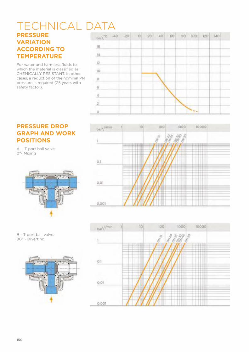
PRESSURE VARIATION ACCORDING TO TEMPERATURE
For water and harmless fluids to which the material is classified as CHEMICALLY RESISTANT. In other cases, a reduction of the nominal PN pressure is required (25 years with safety factor).
PRESSURE DROP GRAPH AND WORK POSITIONS
A - T-port ball valve:0°- Mixing
B - T-port ball valve:90° - Diverting
150
TECHNICAL DATA

C - T-port ball valve:180° - Branch closed/direct flow
D - T-port ball valve:270° - Diverting
E - L-port ball valve:0°/270° - Diverting
151
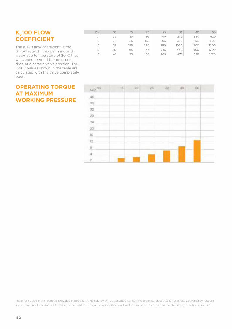
KV100 FLOW
COEFFICIENT
The Kv100 flow coefficient is the
Q flow rate of litres per minute of water at a temperature of 20°C that will generate Δp= 1 bar pressure drop at a certain valve position. The Kv100 values shown in the table are calculated with the valve completely open.
DN 10 15 20 25 32 40 50
A 25 35 95 140 270 330 620
B 37 55 135 205 390 475 900
C 78 195 380 760 1050 1700 3200
D 40 65 145 245 460 600 1200
E 48 73 150 265 475 620 1220
OPERATING TORQUE AT MAXIMUM WORKING PRESSURE
The information in this leaflet is provided in good faith. No liability will be accepted concerning technical data that is not directly covered by recogni-
sed international standards. FIP reserves the right to carry out any modification. Products must be installed and maintained by qualified personnel.
152
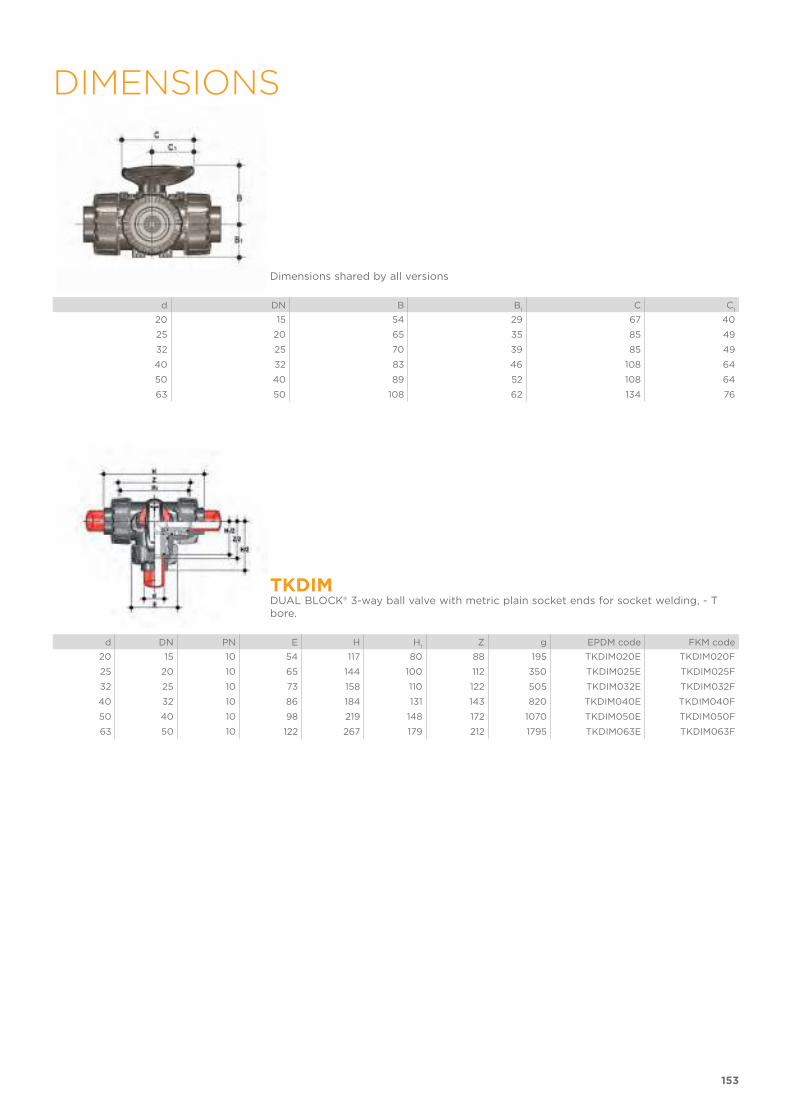
153
DIMENSIONS
Dimensions shared by all versions
d DN B B1
C C1
20 15 54 29 67 40
25 20 65 35 85 49
32 25 70 39 85 49
40 32 83 46 108 64
50 40 89 52 108 64
63 50 108 62 134 76
TKDIMDUAL BLOCK® 3-way ball valve with metric plain socket ends for socket welding, - T bore.
d DN PN E H H1
Z g EPDM code FKM code
20 15 10 54 117 80 88 195 TKDIM020E TKDIM020F
25 20 10 65 144 100 112 350 TKDIM025E TKDIM025F
32 25 10 73 158 110 122 505 TKDIM032E TKDIM032F
40 32 10 86 184 131 143 820 TKDIM040E TKDIM040F
50 40 10 98 219 148 172 1070 TKDIM050E TKDIM050F
63 50 10 122 267 179 212 1795 TKDIM063E TKDIM063F

154
LKDIMDUAL BLOCK® 3-way ball valve with metric plain socket ends for socket welding, - L bore.
d DN PN E H H1
Z g EPDM code FKM code
20 15 10 54 117 80 88 195 LKDIM020E LKDIM020F
25 20 10 65 144 100 112 350 LKDIM025E LKDIM025F
32 25 10 73 158 110 122 505 LKDIM032E LKDIM032F
40 32 10 86 184 131 143 820 LKDIM040E LKDIM040F
50 40 10 98 219 148 172 1070 LKDIM050E LKDIM050F
63 50 10 122 267 179 212 1795 LKDIM063E LKDIM063F
TKDDMDUAL BLOCK® 3-way ball valve with male ends for socket welding, metric series, T-port ball.
d DN PN E H H1
L g EPDM code FKM code
20 15 10 54 140 80 16 205 TKDDM020E TKDDM020F
25 20 10 65 175 100 18 360 TKDDM025E TKDDM025F
32 25 10 73 188 110 20 515 TKDDM032E TKDDM032F
40 32 10 86 220 131 22 835 TKDDM040E TKDDM040F
50 40 10 98 251 148 23 1100 TKDDM050E TKDDM050F
63 50 10 122 294 179 29 1830 TKDDM063E TKDDM063F
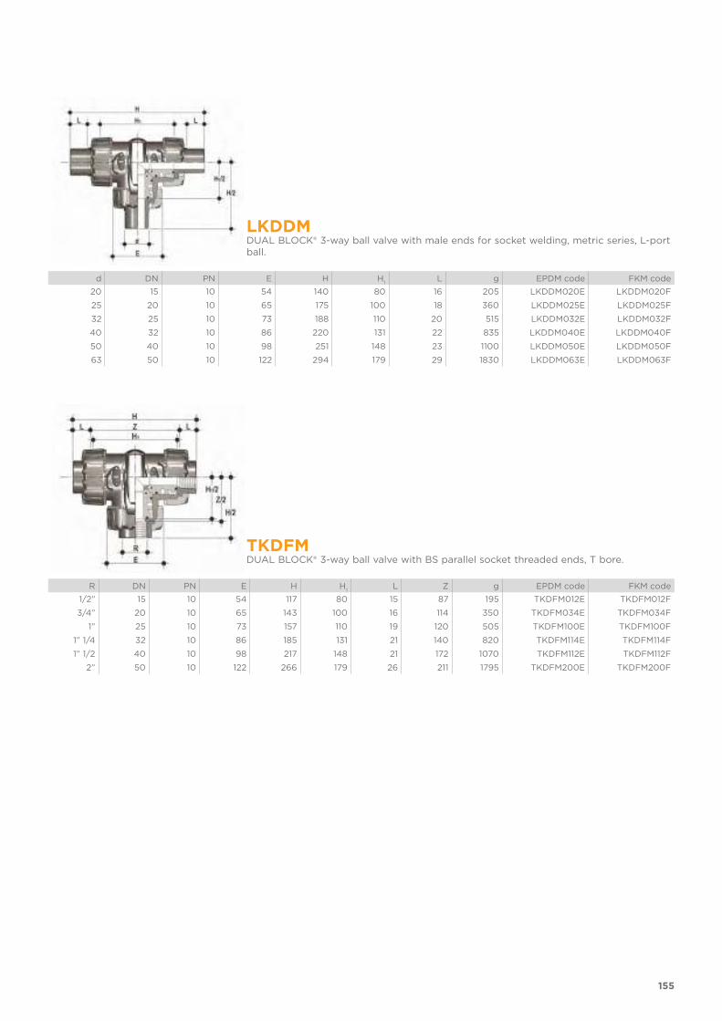
155
LKDDMDUAL BLOCK® 3-way ball valve with male ends for socket welding, metric series, L-port ball.
d DN PN E H H1
L g EPDM code FKM code
20 15 10 54 140 80 16 205 LKDDM020E LKDDM020F
25 20 10 65 175 100 18 360 LKDDM025E LKDDM025F
32 25 10 73 188 110 20 515 LKDDM032E LKDDM032F
40 32 10 86 220 131 22 835 LKDDM040E LKDDM040F
50 40 10 98 251 148 23 1100 LKDDM050E LKDDM050F
63 50 10 122 294 179 29 1830 LKDDM063E LKDDM063F
TKDFMDUAL BLOCK® 3-way ball valve with BS parallel socket threaded ends, T bore.
R DN PN E H H1
L Z g EPDM code FKM code
1/2” 15 10 54 117 80 15 87 195 TKDFM012E TKDFM012F
3/4” 20 10 65 143 100 16 114 350 TKDFM034E TKDFM034F
1” 25 10 73 157 110 19 120 505 TKDFM100E TKDFM100F
1” 1/4 32 10 86 185 131 21 140 820 TKDFM114E TKDFM114F
1” 1/2 40 10 98 217 148 21 172 1070 TKDFM112E TKDFM112F
2” 50 10 122 266 179 26 211 1795 TKDFM200E TKDFM200F

156
LKDFMDUAL BLOCK® 3-way ball valve with BS parallel socket threaded ends, L bore.
R DN PN E H H1
L Z g EPDM code FKM code
1/2” 15 10 54 117 80 15 87 195 LKDFM012E LKDFM012F
3/4” 20 10 65 143 100 16 114 350 LKDFM034E LKDFM034F
1” 25 10 73 157 110 19 120 505 LKDFM100E LKDFM100F
1” 1/4 32 10 86 185 131 21 140 820 LKDFM114E LKDFM114F
1” 1/2 40 10 98 217 148 21 172 1070 LKDFM112E LKDFM112F
2” 50 10 122 266 179 26 211 1795 LKDFM200E LKDFM200F
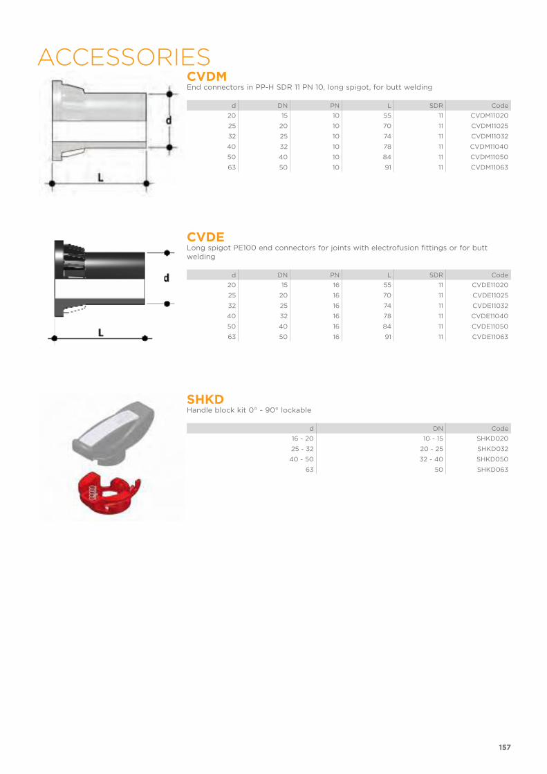
157
ACCESSORIESCVDMEnd connectors in PP-H SDR 11 PN 10, long spigot, for butt welding
d DN PN L SDR Code
20 15 10 55 11 CVDM11020
25 20 10 70 11 CVDM11025
32 25 10 74 11 CVDM11032
40 32 10 78 11 CVDM11040
50 40 10 84 11 CVDM11050
63 50 10 91 11 CVDM11063
CVDELong spigot PE100 end connectors for joints with electrofusion fittings or for butt welding
d DN PN L SDR Code
20 15 16 55 11 CVDE11020
25 20 16 70 11 CVDE11025
32 25 16 74 11 CVDE11032
40 32 16 78 11 CVDE11040
50 40 16 84 11 CVDE11050
63 50 16 91 11 CVDE11063
SHKDHandle block kit 0° - 90° lockable
d DN Code
16 - 20 10 - 15 SHKD020
25 - 32 20 - 25 SHKD032
40 - 50 32 - 40 SHKD050
63 50 SHKD063

158
LTKDThe LTKD stroke limiter specifically permits handle and ball rotation only at set opening and closing angles. The LTKD090 version permits operations for 90° angles while the LTKD180 version for 180° angles. The LTKD stroke limiter is made up of a single removable plate made of technopolymer. Designed for ISO 5211 bore and specifically designed to be directly housed on the valve body mounting flange. It is secured to the valve body by self-tapping screws or plastic rivets.
d DN 90° code 180° code
16 - 20 10 - 15 LTKD090020 LTKD180020
25 - 32 20 - 25 LTKD090032 LTKD180032
40 - 50 32 - 40 LTKD090050 LTKD180050
63 50 LTKD090063 LTKD180063
PSKDStem extension
d DN A A1
A2
E B B1
B min
Code
20 15 32 25 32 54 70 29 139,5 PSKD020
25 20 32 25 40 65 89 34,5 164,5 PSKD025
32 25 32 25 40 73 93,5 39 169 PSKD032
40 32 40 32 50 86 110 46 200 PSKD040
50 40 40 32 50 98 116 52 206 PSKD050
63 50 40 32 59 122 122 62 225 PSKD063
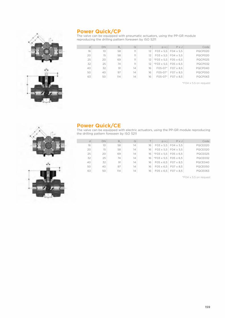
159
Power Quick/CPThe valve can be equipped with pneumatic actuators, using the PP-GR module reproducing the drilling pattern foreseen by ISO 5211
d DN B2
Q T p x j P x J Code
16 10 58 11 12 F03 x 5,5 F04 x 5,5 PQCP020
20 15 58 11 12 F03 x 5,5 F04 x 5,5 PQCP020
25 20 69 11 12 *F03 x 5,5 F05 x 6,5 PQCP025
32 25 74 11 12 *F03 x 5,5 F05 x 6,5 PQCP032
40 32 91 14 16 F05-07* F07 x 8,5 PQCP040
50 40 97 14 16 F05-07* F07 x 8,5 PQCP050
63 50 114 14 16 F05-07* F07 x 8,5 PQCP063
*F04 x 5.5 on request
Power Quick/CEThe valve can be equipped with electric actuators, using the PP-GR module reproducing the drilling pattern foreseen by ISO 5211
d DN B2
Q T p x j P x J Code
16 10 58 14 16 F03 x 5,5 F04 x 5,5 PQCE020
20 15 58 14 16 F03 x 5,5 F04 x 5,5 PQCE020
25 20 69 14 16 *F03 x 5,5 F05 x 6,5 PQCE025
32 25 74 14 16 *F03 x 5,5 F05 x 6,5 PQCE032
40 32 91 14 16 F05 x 6,5 F07 x 8,5 PQCE040
50 40 97 14 16 F05 x 6,5 F07 x 8,5 PQCE050
63 50 114 14 16 F05 x 6,5 F07 x 8,5 PQCE063
*F04 x 5.5 on request

160
MSKDMSKD is a limit switch box with electromechanical or inductive micro switches to remotely signal the valve position (maximum 90° rotation). Manual valve installation is possible using the Power Quick actuation module. The box can be assembled on the TKD valve even if already installed on the system.
d DN A A1
B B1
C C1
Mechanical codeInductive (2 wires)
code Inductive Namur
code
16 10 58 85 132,5 29 88,5 134 MSKD1M MSKD1I MSKD1N
20 15 58 85 132,5 29 88,5 134 MSKD1M MSKD1I MSKD1N
25 20 70,5 96 143,5 34,5 88,5 134 MSKD1M MSKD1I MSKD1N
32 25 74 101 148,5 39 88,5 134 MSKD1M MSKD1I MSKD1N
40 32 116 118 165,5 46 88,5 167 MSKD2M MSKD2I MSKD2N
50 40 122 124 171,5 52 88,5 167 MSKD2M MSKD2I MSKD2N
63 50 139 141 188,5 62 88,5 167 MSKD2M MSKD2I MSKD2N
Electromechanical Inductive Namur
WH = white; BK = black; BL = blue; BR = brown
Switch type Flow rateLifetime[drives]
Operatingvoltage
Nominalvoltage
Workingpressure
Voltage dropNo-load
supplycurrent
Protectionrate
Electromechanical 250 V - 5 A 3 x 10⁷ - - - - - IP65
Inductive - - 5 ÷ 36 V - 4 ÷ 200 mA < 4,6 V < 0,8 mA IP65
Namur* - - 7,5 ÷ 30 V DC** 8,2 V DC < 30 mA** - - IP65
* To be used with an amplifier** Outside areas with explosion risks

All valves, whether manual or actuated, must be adequately supported in many applications.The TKD valve series is therefore provided with an integrated bracket that permits direct anchoring of the valve body without the need of other com-ponents.Using standard threaded nuts (not included) made of STAINLESS steel, you can anchor the valve on 4 fastening points.
d DN g H L J
20 15 31,5 27 20 M5 x 8
25 20 40 30 20 M5 x 8
32 25 40 30 20 M5 x 8
40 32 50 35 30 M6 x 10
50 40 50 35 30 M6 x 10
63 50 60 40 30 M6 x 10
161
FASTENING AND SUPPORTING
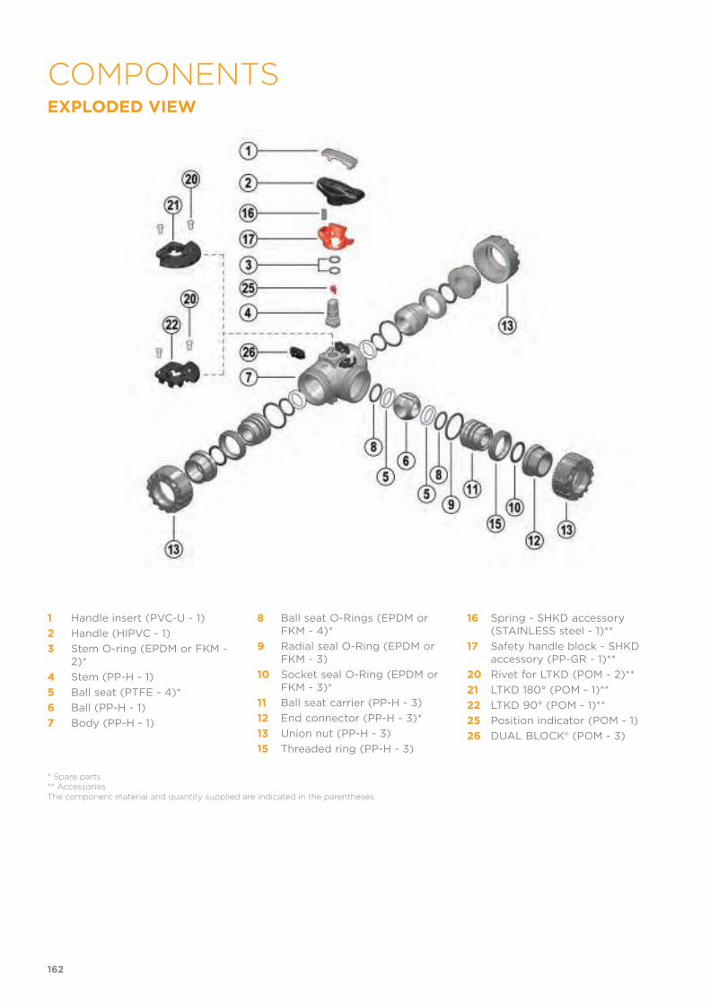
EXPLODED VIEW
1 Handle insert (PVC-U - 1)
2 Handle (HIPVC - 1)
3 Stem O-ring (EPDM or FKM - 2)*
4 Stem (PP-H - 1)
5 Ball seat (PTFE - 4)*
6 Ball (PP-H - 1)
7 Body (PP-H - 1)
8 Ball seat O-Rings (EPDM or FKM - 4)*
9 Radial seal O-Ring (EPDM or FKM - 3)
10 Socket seal O-Ring (EPDM or FKM - 3)*
11 Ball seat carrier (PP-H - 3)
12 End connector (PP-H - 3)*
13 Union nut (PP-H - 3)
15 Threaded ring (PP-H - 3)
16 Spring - SHKD accessory (STAINLESS steel - 1)**
17 Safety handle block - SHKD accessory (PP-GR - 1)**
20 Rivet for LTKD (POM - 2)**
21 LTKD 180° (POM - 1)**
22 LTKD 90° (POM - 1)**
25 Position indicator (POM - 1)
26 DUAL BLOCK® (POM - 3)
* Spare parts** AccessoriesThe component material and quantity supplied are indicated in the parentheses.
162
COMPONENTS

DISASSEMBLY1) Isolate the valve from the line (release
the pressure and empty the pipeline).2) Unlock the union nuts by pressing the
lever on the DUAL BLOCK® (26) along the axis and separate it from the union nut (fig. 1). It is also possible to com-pletely remove the block device from the body of the valve.
3) Unscrew the union nuts (13) and ex-tract the body (7).
4) After turning the handle (2) to the po-sition with the three arrows pointing at the three ports (for L-port ball with two arrows facing the ports a and b), extract the insert (1) from the handle (2) and insert the two protrusions in the corresponding apertures in the threaded rings (15), extracting the car-riers (11) by turning counterclockwise.
5) Extract the ball (6) from the central port being careful not to damage the seat surface.
6) Remove the PTFE ball seats (5) and O-Rings (8, 9, 10) from the carriers (11).
7) Pull the handle (2) upwards to remove it from the stem (4).
8) Press the stem (4) into the body and extract it.
9) Remove the PTFE ball seat (5) with relevant O-ring (8) from inside the valve body.
10) Remove the stem (4) O-rings (3) from their seats.
ASSEMBLY1) Insert the O-rings (3) on the stem (4).2) Insert the O-ring (8) in the seat in the
valve body and, next, the PTFE ball seat (5).
3) Insert the stem (4), from the interi-or, in the body, being sure the three marks on the socket correspond to the three outlets.
4) Insert the ball (6) from the central port b, being careful that the three bores match the three outlets (for L-port ball, the two bores must match the a and b outlets).
5) Insert the O-rings (8), PTFE ball seats (5), socket seal O-rings (10) and radial seal O-rings (9) in their seats on the carriers (11).
6) Insert the three carriers (11) with the relevant threaded rings (15), screwing in clockwise with the handle insert (1) and starting from the one on the cen-tral outlet b.
7) Press the handle (2) on the stem (4), being careful to match the printed ar-rows with the lines on the stem (fig. 2-3).
8) Return the insert (1) in the handle (2)9) Insert the valve between the end con-
nectors (12) and tighten the union nuts (13), making sure that the sock-et seal O-rings (10) do not exit their seats.
Note: during assembly operations, it is advisable to lubricate the rubber seals. Mineral oils are not recommended for this task as they react aggressively with EPDM rubber.
Fig. 1
Fig. 2
Fig. 3
Fig. 4
163
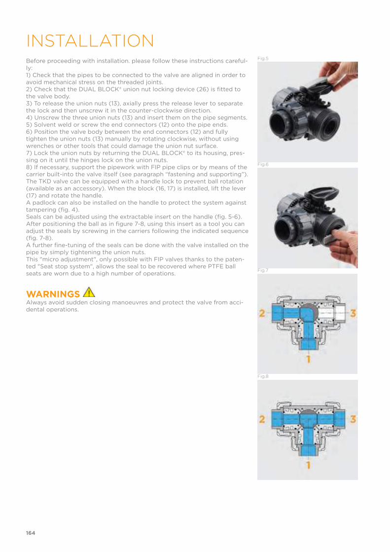
Before proceeding with installation. please follow these instructions careful-ly:1) Check that the pipes to be connected to the valve are aligned in order to avoid mechanical stress on the threaded joints.2) Check that the DUAL BLOCK® union nut locking device (26) is fitted to the valve body.3) To release the union nuts (13), axially press the release lever to separate the lock and then unscrew it in the counter-clockwise direction.4) Unscrew the three union nuts (13) and insert them on the pipe segments.5) Solvent weld or screw the end connectors (12) onto the pipe ends.6) Position the valve body between the end connectors (12) and fully tighten the union nuts (13) manually by rotating clockwise, without using wrenches or other tools that could damage the union nut surface.7) Lock the union nuts by returning the DUAL BLOCK® to its housing, pres-sing on it until the hinges lock on the union nuts.8) If necessary, support the pipework with FIP pipe clips or by means of the carrier built-into the valve itself (see paragraph “fastening and supporting”).The TKD valve can be equipped with a handle lock to prevent ball rotation (available as an accessory). When the block (16, 17) is installed, lift the lever (17) and rotate the handle.A padlock can also be installed on the handle to protect the system against tampering (fig. 4).Seals can be adjusted using the extractable insert on the handle (fig. 5-6). After positioning the ball as in figure 7-8, using this insert as a tool you can adjust the seals by screwing in the carriers following the indicated sequence (fig. 7-8).A further fine-tuning of the seals can be done with the valve installed on the pipe by simply tightening the union nuts.This "micro adjustment", only possible with FIP valves thanks to the paten-ted "Seat stop system", allows the seal to be recovered where PTFE ball seats are worn due to a high number of operations.
WARNINGS Always avoid sudden closing manoeuvres and protect the valve from acci-dental operations.
Fig.5
Fig.6
Fig.7
Fig.8
164
INSTALLATION


SR DN 15÷50
PP-H
Ball check valve
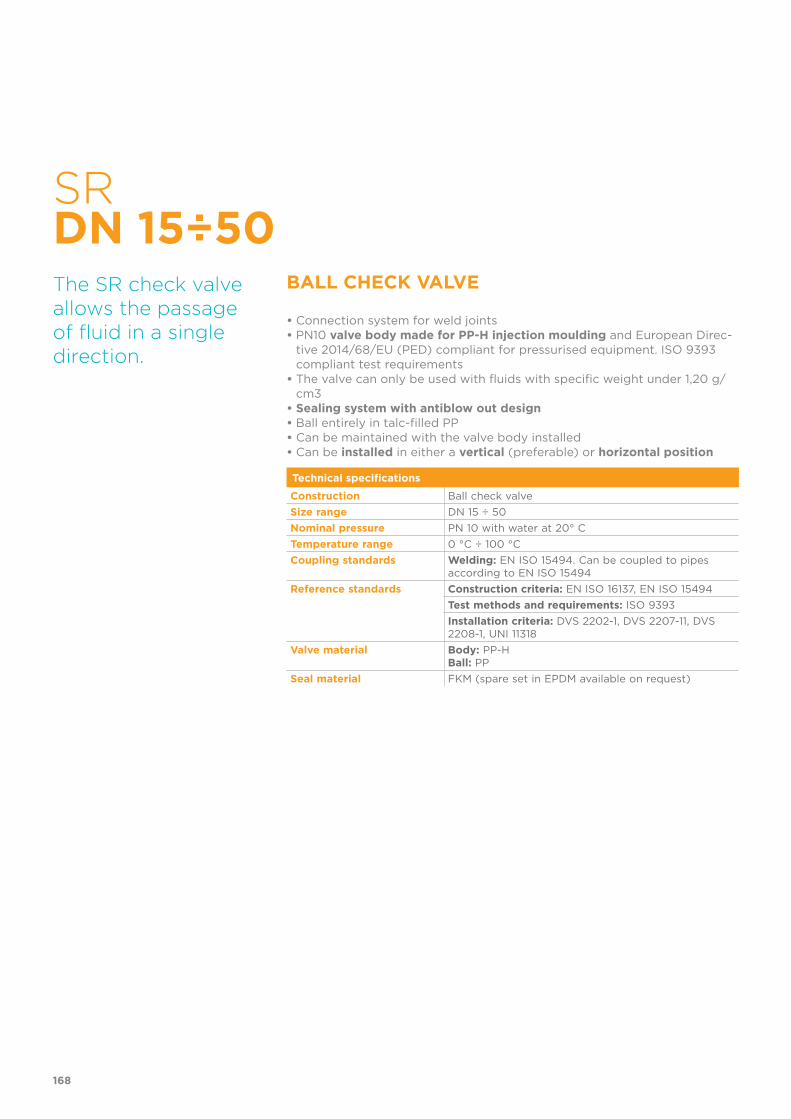
SR DN 15÷50
BALL CHECK VALVE
• Connection system for weld joints• PN10 valve body made for PP-H injection moulding and European Direc-
tive 2014/68/EU (PED) compliant for pressurised equipment. ISO 9393 compliant test requirements
• The valve can only be used with fluids with specific weight under 1,20 g/cm3
• Sealing system with antiblow out design• Ball entirely in talc-filled PP• Can be maintained with the valve body installed• Can be installed in either a vertical (preferable) or horizontal position
The SR check valve allows the passage of fluid in a single direction.
Technical specifications
Construction Ball check valve
Size range DN 15 ÷ 50
Nominal pressure PN 10 with water at 20° C
Temperature range 0 °C ÷ 100 °C
Coupling standards Welding: EN ISO 15494. Can be coupled to pipes according to EN ISO 15494
Reference standards Construction criteria: EN ISO 16137, EN ISO 15494
Test methods and requirements: ISO 9393
Installation criteria: DVS 2202-1, DVS 2207-11, DVS 2208-1, UNI 11318
Valve material Body: PP-HBall: PP
Seal material FKM (spare set in EPDM available on request)
168
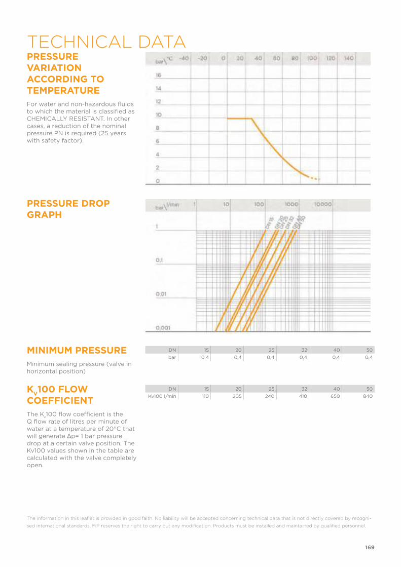
PRESSURE VARIATION ACCORDING TO TEMPERATURE
For water and non-hazardous fluids to which the material is classified as CHEMICALLY RESISTANT. In other cases, a reduction of the nominal pressure PN is required (25 years with safety factor).
PRESSURE DROP GRAPH
MINIMUM PRESSURE
Minimum sealing pressure (valve in horizontal position)
DN 15 20 25 32 40 50
bar 0,4 0,4 0,4 0,4 0,4 0,4
KV100 FLOW
COEFFICIENT
The Kv100 flow coefficient is the
Q flow rate of litres per minute of water at a temperature of 20°C that will generate Δp= 1 bar pressure drop at a certain valve position. The Kv100 values shown in the table are calculated with the valve completely open.
DN 15 20 25 32 40 50
Kv100 l/min 110 205 240 410 650 840
The information in this leaflet is provided in good faith. No liability will be accepted concerning technical data that is not directly covered by recogni-
sed international standards. FiP reserves the right to carry out any modification. Products must be installed and maintained by qualified personnel.
169
TECHNICAL DATA
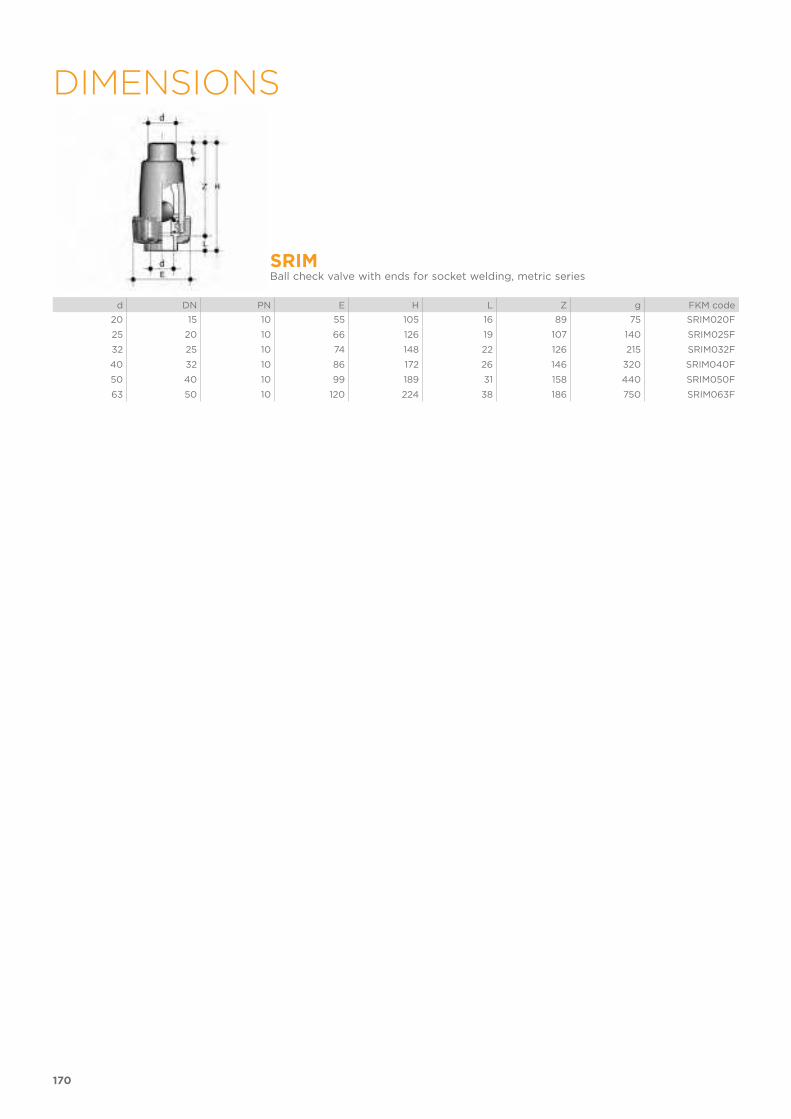
170
DIMENSIONS
SRIMBall check valve with ends for socket welding, metric series
d DN PN E H L Z g FKM code
20 15 10 55 105 16 89 75 SRIM020F
25 20 10 66 126 19 107 140 SRIM025F
32 25 10 74 148 22 126 215 SRIM032F
40 32 10 86 172 26 146 320 SRIM040F
50 40 10 99 189 31 158 440 SRIM050F
63 50 10 120 224 38 186 750 SRIM063F
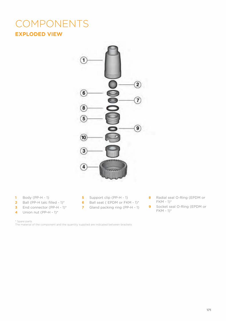
EXPLODED VIEW
1 Body (PP-H - 1)
2 Ball (PP-H talc filled - 1)*
3 End connector (PP-H - 1)*
4 Union nut (PP-H - 1)*
5 Support clip (PP-H - 1)
6 Ball seat ( EPDM or FKM - 1)*
7 Gland packing ring (PP-H - 1)
8 Radial seal O-Ring (EPDM or FKM - 1)*
9 Socket seal O-Ring (EPDM or FKM - 1)*
* Spare partsThe material of the component and the quantity supplied are indicated between brackets
171
COMPONENTS
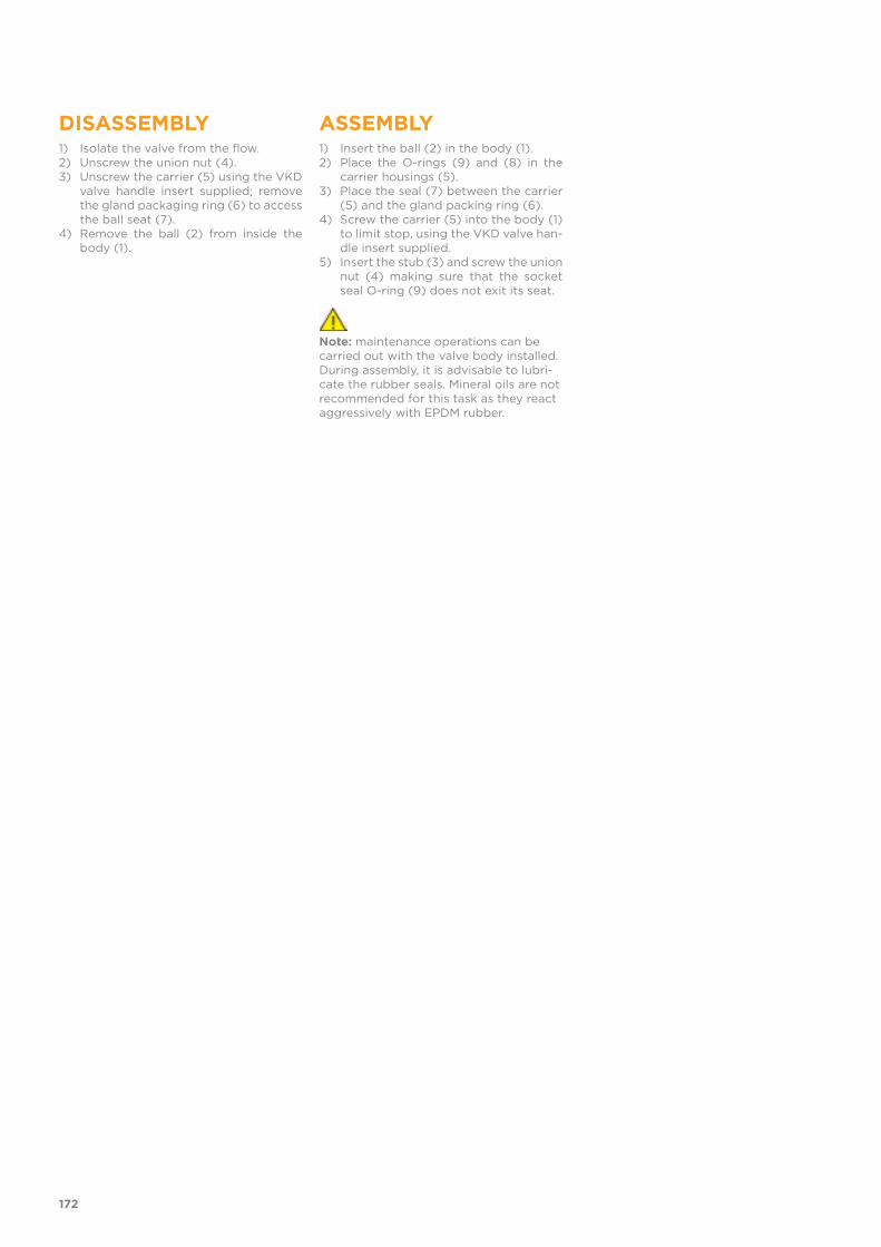
DISASSEMBLY1) Isolate the valve from the flow.2) Unscrew the union nut (4).3) Unscrew the carrier (5) using the VKD
valve handle insert supplied; remove the gland packaging ring (6) to access the ball seat (7).
4) Remove the ball (2) from inside the body (1).
ASSEMBLY1) Insert the ball (2) in the body (1).2) Place the O-rings (9) and (8) in the
carrier housings (5).3) Place the seal (7) between the carrier
(5) and the gland packing ring (6).4) Screw the carrier (5) into the body (1)
to limit stop, using the VKD valve han-dle insert supplied.
5) Insert the stub (3) and screw the union nut (4) making sure that the socket seal O-ring (9) does not exit its seat.
Note: maintenance operations can be carried out with the valve body installed. During assembly, it is advisable to lubri-cate the rubber seals. Mineral oils are not recommended for this task as they react aggressively with EPDM rubber.
172

1) The SR check valve can be installed on vertical or horizontal axis pipes.2) Install the valve such that the arrow on the body indicates the direction of fluid flow.
173
INSTALLATION

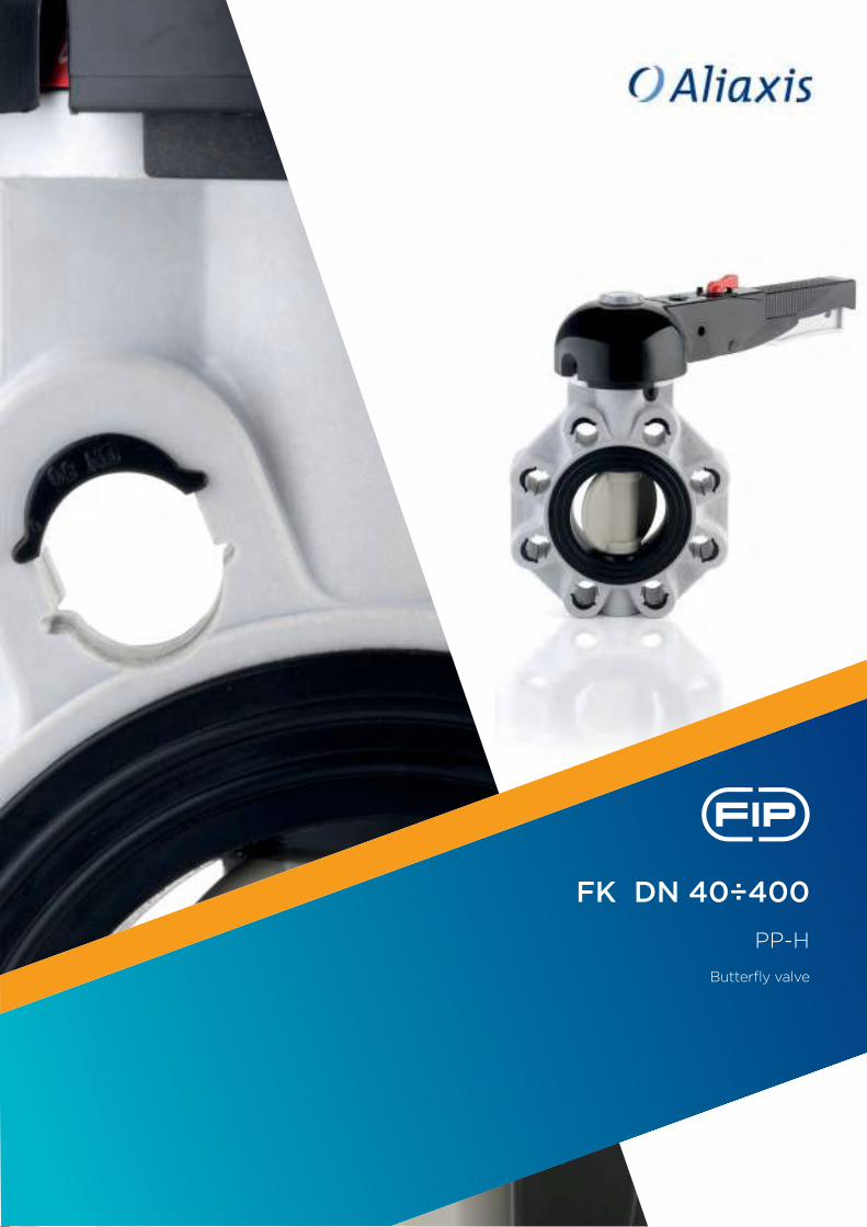
FK DN 40÷400
PP-H
Butterfly valve

FK DN 40÷400
BUTTERFLY VALVE
• Interchangeable Disk in PP-H with through shaft, available in different thermoplastic materials: PVC-U, PVC-C, ABS, PVDF
• Overall dimensions of the valve in accordance with standard ISO 5752 (DN 40÷200 Medium series 25, DN 250÷ 300 Long Series 16) and DIN 3202 K2 and ISO 5752 (DN DN 65÷200 K2, DN 250÷300 K3)
• Can also be installed as an end line valve, bottom discharge valve or tank dump valve
• Special Lug version PN 10 fully drilled according to DIN 2501 or ANSI B16.5 cl.150 with molded-in AISI 316 stainless steel threaded inserts
• Valve material compatibility (PP-H) with water conveyance, drinking wa-ter and other food substances according to current regulations
• Possibility of installing a manual reducer or pneumatic and/or electric actuators by applying an ISO standard drilling PP-GR flanges. DN 40 ÷ 200 valve equipped with plate with rack in PP-GR. For actuated versions with flange drilled according to ISO 5211 F05, F07, F10. DN 250÷300 valve, fitted with one-piece top flange in high mechanical strength PP-GR with mounting flange for internal components drilled according to standard ISO 5211 F10 (excluding DN 350÷400), F12, F14.
The FK is a butterfly valve for shutting off or regulating flow, with structural characteristics that make it ideal for industrial applications requiring high performance and longterm reliability. Thisvalve is also equipped with the customisable Labelling System. Technical specifications
Construction Bi-directional centric butterfly valve
Size range DN 40 ÷ 400
Nominal pressure Wafer versionrDN 40 ÷ 250: PN 10 with water at 20° CDN 300: PN 8 with water at 20° CDN 350: PN 7 with water at 20° CDN 400: PN 6 with water at 20° CLug versionDN 65÷200: PN 10 with water at 20° CDN 250÷300: PN 6 with water at 20° C
Temperature range 0 °C ÷ 100 °C
Coupling standards Flanging system: EN ISO 15494, DIN 2501, ISO 7005-1, EN 1092-1, ANSI B16.5 Cl.150, JIS B 2220
Reference standards Construction criteria: EN ISO 16136, EN ISO 15494
Test methods and requirements: ISO 9393
Actuator couplings: ISO 5211
Valve material Body: PP-GRDisk: PP-HStem: AISI steel 316
Seal material Liner: EPDM, FKM
Control options Manual control (DN 40÷200); Gearbox, pneumatic actuator, electric actuator
176
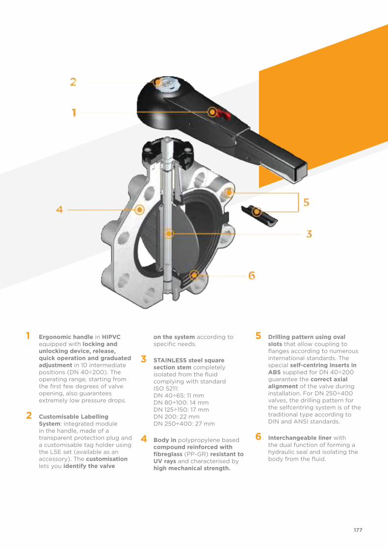
1 Ergonomic handle in HIPVC equipped with locking and unlocking device, release, quick operation and graduated adjustment in 10 intermediate positions (DN 40÷200). The operating range, starting from the first few degrees of valve opening, also guarantees extremely low pressure drops.
2 Customisable Labelling System: integrated module in the handle, made of a transparent protection plug and a customisable tag holder using the LSE set (available as an accessory). The customisation lets you identify the valve
on the system according to specific needs.
3 STAINLESS steel square section stem completely isolated from the fluid complying with standard ISO 5211: DN 40÷65: 11 mm DN 80÷100: 14 mm DN 125÷150: 17 mm DN 200: 22 mm DN 250÷400: 27 mm
4 Body in polypropylene based compound reinforced with fibreglass (PP-GR) resistant to UV rays and characterised by high mechanical strength.
5 Drilling pattern using oval slots that allow coupling to flanges according to numerous international standards. The special self-centring inserts in ABS supplied for DN 40÷200 guarantee the correct axial alignment of the valve during installation. For DN 250÷400 valves, the drilling pattern for the selfcentring system is of the traditional type according to DIN and ANSI standards.
6 Interchangeable liner with the dual function of forming a hydraulic seal and isolating the body from the fluid.
177
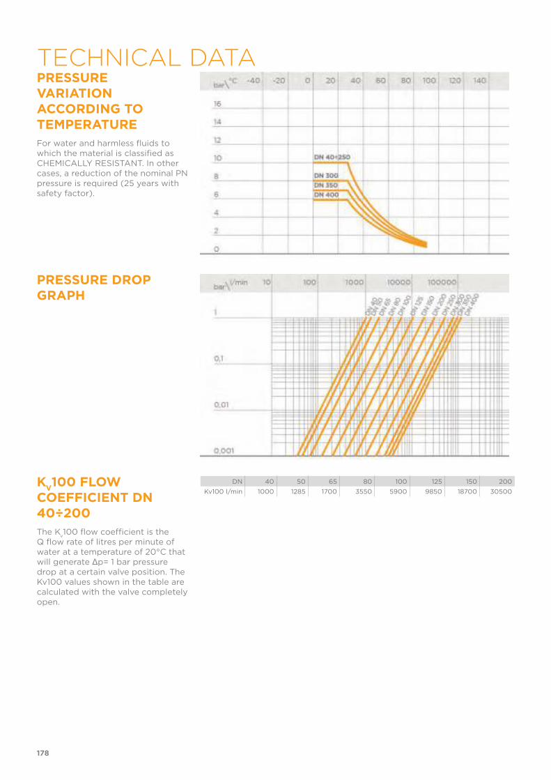
PRESSURE VARIATION ACCORDING TO TEMPERATURE
For water and harmless fluids to which the material is classified as CHEMICALLY RESISTANT. In other cases, a reduction of the nominal PN pressure is required (25 years with safety factor).
PRESSURE DROP GRAPH
KV100 FLOW
COEFFICIENT DN 40÷200
The Kv100 flow coefficient is the
Q flow rate of litres per minute of water at a temperature of 20°C that will generate Δp= 1 bar pressure drop at a certain valve position. The Kv100 values shown in the table are calculated with the valve completely open.
DN 40 50 65 80 100 125 150 200
Kv100 l/min 1000 1285 1700 3550 5900 9850 18700 30500
178
TECHNICAL DATA
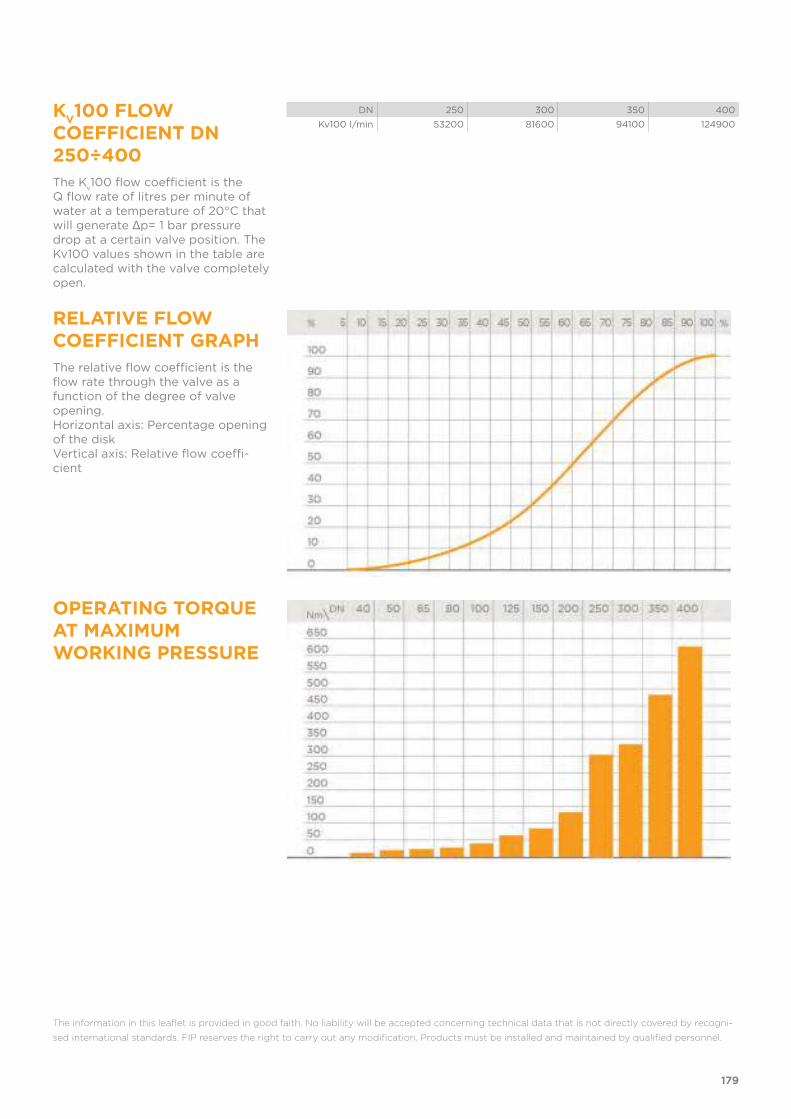
KV100 FLOW
COEFFICIENT DN 250÷400
The Kv100 flow coefficient is the
Q flow rate of litres per minute of water at a temperature of 20°C that will generate Δp= 1 bar pressure drop at a certain valve position. The Kv100 values shown in the table are calculated with the valve completely open.
DN 250 300 350 400
Kv100 l/min 53200 81600 94100 124900
RELATIVE FLOW COEFFICIENT GRAPH
The relative flow coefficient is the flow rate through the valve as a function of the degree of valve opening.Horizontal axis: Percentage opening of the diskVertical axis: Relative flow coeffi-cient
OPERATING TORQUE AT MAXIMUM WORKING PRESSURE
The information in this leaflet is provided in good faith. No liability will be accepted concerning technical data that is not directly covered by recogni-
sed international standards. FIP reserves the right to carry out any modification. Products must be installed and maintained by qualified personnel.
179
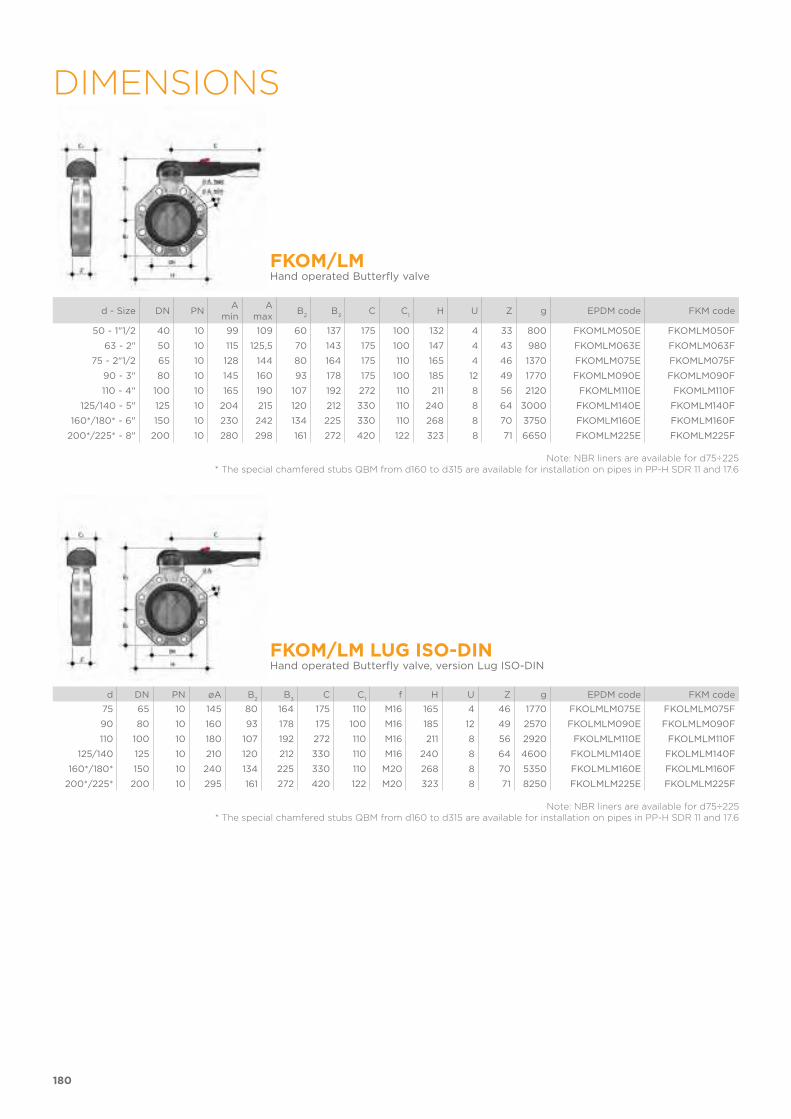
180
DIMENSIONS
FKOM/LMHand operated Butterfly valve
d - Size DN PNA
minA
maxB
2B
3C C
1H U Z g EPDM code FKM code
50 - 1"1/2 40 10 99 109 60 137 175 100 132 4 33 800 FKOMLM050E FKOMLM050F
63 - 2" 50 10 115 125,5 70 143 175 100 147 4 43 980 FKOMLM063E FKOMLM063F
75 - 2"1/2 65 10 128 144 80 164 175 110 165 4 46 1370 FKOMLM075E FKOMLM075F
90 - 3" 80 10 145 160 93 178 175 100 185 12 49 1770 FKOMLM090E FKOMLM090F
110 - 4" 100 10 165 190 107 192 272 110 211 8 56 2120 FKOMLM110E FKOMLM110F
125/140 - 5" 125 10 204 215 120 212 330 110 240 8 64 3000 FKOMLM140E FKOMLM140F
160*/180* - 6" 150 10 230 242 134 225 330 110 268 8 70 3750 FKOMLM160E FKOMLM160F
200*/225* - 8" 200 10 280 298 161 272 420 122 323 8 71 6650 FKOMLM225E FKOMLM225F
Note: NBR liners are available for d75÷225* The special chamfered stubs QBM from d160 to d315 are available for installation on pipes in PP-H SDR 11 and 17.6
FKOM/LM LUG ISO-DINHand operated Butterfly valve, version Lug ISO-DIN
d DN PN øA B2
B3
C C1
f H U Z g EPDM code FKM code
75 65 10 145 80 164 175 110 M16 165 4 46 1770 FKOLMLM075E FKOLMLM075F
90 80 10 160 93 178 175 100 M16 185 12 49 2570 FKOLMLM090E FKOLMLM090F
110 100 10 180 107 192 272 110 M16 211 8 56 2920 FKOLMLM110E FKOLMLM110F
125/140 125 10 210 120 212 330 110 M16 240 8 64 4600 FKOLMLM140E FKOLMLM140F
160*/180* 150 10 240 134 225 330 110 M20 268 8 70 5350 FKOLMLM160E FKOLMLM160F
200*/225* 200 10 295 161 272 420 122 M20 323 8 71 8250 FKOLMLM225E FKOLMLM225F
Note: NBR liners are available for d75÷225* The special chamfered stubs QBM from d160 to d315 are available for installation on pipes in PP-H SDR 11 and 17.6

181
FKOM/LM LUG ANSIHand operated Butterfly valve, version Lug ANSI
d DN PN øA B2
B3
C C1
f H U Z g EPDM code FKM code
2” 1/2 65 10 140 119 80 175 110 5/8” 165 4 46 1770 FKOALMLM212E FKOALMLM212F
3” 80 10 152 133 93 175 100 5/8” 185 12 49 2570 FKOALMLM300E FKOALMLM300F
4” 100 10 191 147 107 272 110 5/8” 211 8 56 2920 FKOALMLM400E FKOALMLM400F
5” 125 10 216 167 120 330 110 3/4” 240 8 64 4600 FKOALMLM500E FKOALMLM500F
6” 150 10 241 180 134 330 110 3/4” 268 8 70 5350 FKOALMLM600E FKOALMLM600F
8” 200 10 298 227 161 420 122 3/4” 323 8 71 8250 FKOALMLM800E FKOALMLM800F
Note: NBR liners are available for d 2 1/2”÷ 8”
FKOM/FMButterfly valve with bare shaft
d - Size DN PNA
minA
maxøA B
1B
2f H U Z g EPDM code EPDM code
50 - 1"1/2 40 10 99 109 - 106 60 19 132 4 33 474 FKOMFM050E FKOMFM050F
63 - 2" 50 10 115 126 - 112 70 19 147 4 43 654 FKOMFM063E FKOMFM063F
75 - 2"1/2 65 10 128 144 - 119 80 19 165 4 46 900 FKOMFM075E FKOMFM075F
90 - 3" 80 10 145 160 - 133 93 19 185 12 49 1300 FKOMFM090E FKOMFM090F
110 - 4" 100 10 165 190 - 147 107 19 211 8 56 1650 FKOMFM110E FKOMFM110F
125/140 - 5" 125 10 204 215 - 167 120 23 240 8 64 2450 FKOMFM140E FKOMFM140F
160*/180 - 6" 150 10 230 242 - 180 134 23 268 8 70 3200 FKOMFM160E FKOMFM160F
200*/225* - 8" 200 10 280 298 - 227 161 23 323 8 71 5900 FKOMFM225E FKOMFM225F
250*/280* **250 10 - - 350 248 210 22 405 12 114 11800 FKOMFM280E FKOMFM280F
315* **300 8 - - 400 305 245 22 475 12 114 18700 FKOMFM315E FKOMFM315F
355* **350 7 - - 460 330 280 22 530 16 129 23315 FKOMFM355E FKOMFM355F
400* **400 6 - - 515 350 306 26 594 16 169 30310 FKOMFM400E FKOMFM400F
10" ***250 10 - - 362 248 210 25,4 405 12 114 11800 FKOAMFM810E FKOAMFM810F
12" ***300 8 - - 432 305 245 25,4 475 12 114 18700 FKOAMFM812E FKOAMFM812F
14" ***350 7 - - 476 330 280 28,5 530 12 129 23315 FKOAMFM814E FKOAMFM814F
16" ***400 6 - - 540 350 306 28,5 594 16 169 30310 FKOAMFM816E FKOAMFM816F
Note: NBR liners are available for d75÷225* The special chamfered stubs QBM from d160 to d315 are available for installation on pipes in PP-H SDR 11 and 17.6
**ISO-DIN***ANSI B.16.5 150
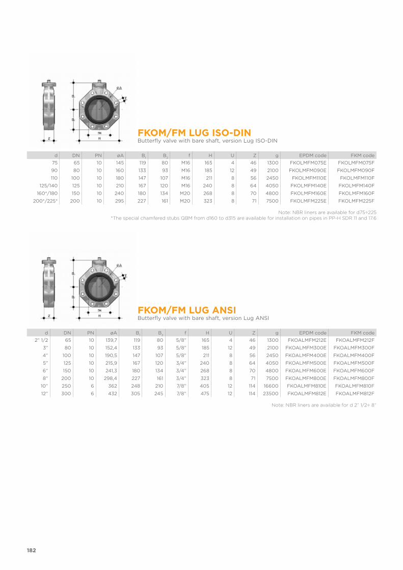
182
FKOM/FM LUG ISO-DINButterfly valve with bare shaft, version Lug ISO-DIN
d DN PN øA B1
B2
f H U Z g EPDM code FKM code
75 65 10 145 119 80 M16 165 4 46 1300 FKOLMFM075E FKOLMFM075F
90 80 10 160 133 93 M16 185 12 49 2100 FKOLMFM090E FKOLMFM090F
110 100 10 180 147 107 M16 211 8 56 2450 FKOLMFM110E FKOLMFM110F
125/140 125 10 210 167 120 M16 240 8 64 4050 FKOLMFM140E FKOLMFM140F
160*/180 150 10 240 180 134 M20 268 8 70 4800 FKOLMFM160E FKOLMFM160F
200*/225* 200 10 295 227 161 M20 323 8 71 7500 FKOLMFM225E FKOLMFM225F
Note: NBR liners are available for d75÷225 *The special chamfered stubs QBM from d160 to d315 are available for installation on pipes in PP-H SDR 11 and 17.6
FKOM/FM LUG ANSIButterfly valve with bare shaft, version Lug ANSI
d DN PN øA B1
B2
f H U Z g EPDM code FKM code
2” 1/2 65 10 139,7 119 80 5/8” 165 4 46 1300 FKOALMFM212E FKOALMFM212F
3” 80 10 152,4 133 93 5/8” 185 12 49 2100 FKOALMFM300E FKOALMFM300F
4” 100 10 190,5 147 107 5/8” 211 8 56 2450 FKOALMFM400E FKOALMFM400F
5” 125 10 215,9 167 120 3/4” 240 8 64 4050 FKOALMFM500E FKOALMFM500F
6” 150 10 241,3 180 134 3/4” 268 8 70 4800 FKOALMFM600E FKOALMFM600F
8” 200 10 298,4 227 161 3/4” 323 8 71 7500 FKOALMFM800E FKOALMFM800F
10” 250 6 362 248 210 7/8” 405 12 114 16600 FKOALMFM810E FKOALMFM810F
12” 300 6 432 305 245 7/8” 475 12 114 23500 FKOALMFM812E FKOALMFM812F
Note: NBR liners are available for d 2” 1/2÷ 8”
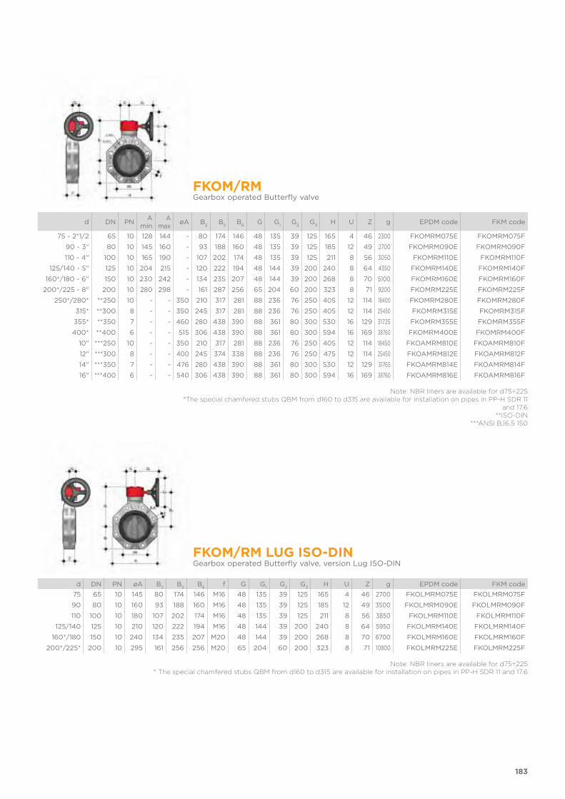
183
FKOM/RMGearbox operated Butterfly valve
d DN PNA
minA
maxøA B
2B
5B
6G G
1G
2G
3H U Z g EPDM code FKM code
75 - 2"1/2 65 10 128 144 - 80 174 146 48 135 39 125 165 4 46 2300 FKOMRM075E FKOMRM075F
90 - 3" 80 10 145 160 - 93 188 160 48 135 39 125 185 12 49 2700 FKOMRM090E FKOMRM090F
110 - 4" 100 10 165 190 - 107 202 174 48 135 39 125 211 8 56 3050 FKOMRM110E FKOMRM110F
125/140 - 5" 125 10 204 215 - 120 222 194 48 144 39 200 240 8 64 4350 FKOMRM140E FKOMRM140F
160*/180 - 6" 150 10 230 242 - 134 235 207 48 144 39 200 268 8 70 5100 FKOMRM160E FKOMRM160F
200*/225 - 8" 200 10 280 298 - 161 287 256 65 204 60 200 323 8 71 9200 FKOMRM225E FKOMRM225F
250*/280* **250 10 - - 350 210 317 281 88 236 76 250 405 12 114 18400 FKOMRM280E FKOMRM280F
315* **300 8 - - 350 245 317 281 88 236 76 250 405 12 114 25450 FKOMRM315E FKOMRM315F
355* **350 7 - - 460 280 438 390 88 361 80 300 530 16 129 31725 FKOMRM355E FKOMRM355F
400* **400 6 - - 515 306 438 390 88 361 80 300 594 16 169 38760 FKOMRM400E FKOMRM400F
10" ***250 10 - - 350 210 317 281 88 236 76 250 405 12 114 18450 FKOAMRM810E FKOAMRM810F
12" ***300 8 - - 400 245 374 338 88 236 76 250 475 12 114 25450 FKOAMRM812E FKOAMRM812F
14" ***350 7 - - 476 280 438 390 88 361 80 300 530 12 129 31765 FKOAMRM814E FKOAMRM814F
16" ***400 6 - - 540 306 438 390 88 361 80 300 594 16 169 38760 FKOAMRM816E FKOAMRM816F
Note: NBR liners are available for d75÷225*The special chamfered stubs QBM from d160 to d315 are available for installation on pipes in PP-H SDR 11
and 17.6**ISO-DIN
***ANSI B.16.5 150
FKOM/RM LUG ISO-DINGearbox operated Butterfly valve, version Lug ISO-DIN
d DN PN øA B2
B5
B6
f G G1
G2
G3
H U Z g EPDM code FKM code
75 65 10 145 80 174 146 M16 48 135 39 125 165 4 46 2700 FKOLMRM075E FKOLMRM075F
90 80 10 160 93 188 160 M16 48 135 39 125 185 12 49 3500 FKOLMRM090E FKOLMRM090F
110 100 10 180 107 202 174 M16 48 135 39 125 211 8 56 3850 FKOLMRM110E FKOLMRM110F
125/140 125 10 210 120 222 194 M16 48 144 39 200 240 8 64 5950 FKOLMRM140E FKOLMRM140F
160*/180 150 10 240 134 235 207 M20 48 144 39 200 268 8 70 6700 FKOLMRM160E FKOLMRM160F
200*/225* 200 10 295 161 256 256 M20 65 204 60 200 323 8 71 10800 FKOLMRM225E FKOLMRM225F
Note: NBR liners are available for d75÷225* The special chamfered stubs QBM from d160 to d315 are available for installation on pipes in PP-H SDR 11 and 17.6

184
FKOM/RM LUG ANSIGearbox operated Butterfly valve, version Lug ANSI
d DN PN øA B2
B5
B6
f G G1
G2
G3
H U Z g EPDM code FKM code
2” 1/2 65 10 140 80 174 146 5/8” 48 135 39 125 165 4 46 2700 FKOALMRM212E FKOALMRM212F
3” 80 10 152 93 188 160 5/8” 48 135 39 125 185 12 49 3500 FKOALMRM300E FKOALMRM300F
4” 100 10 191 107 202 174 5/8” 48 135 39 125 211 8 56 3850 FKOALMRM400E FKOALMRM400F
5” 125 10 216 120 222 194 3/4” 48 144 39 200 240 8 64 5950 FKOALMRM500E FKOALMRM500F
6” 150 10 241 134 235 207 3/4” 48 144 39 200 268 8 70 6700 FKOALMRM600E FKOALMRM600F
8” 200 10 298 161 287 256 3/4” 65 204 60 200 323 8 71 10800 FKOALMRM800E FKOALMRM800F
10” 250 6 362 210 317 281 7/8” 88 236 76 250 405 12 114 23200 FKOALMRM810E FKOALMRM810F
12” 300 6 432 245 374 338 7/8” 88 236 76 250 475 12 114 30250 FKOALMRM812E FKOALMRM812F
Note: NBR liners are available for d 2 1/2”÷ 8”
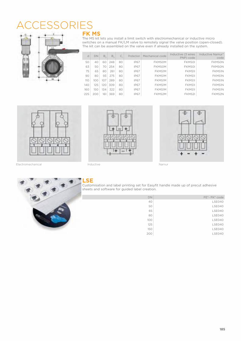
185
ACCESSORIESFK MSThe MS kit lets you install a limit switch with electromechanical or inductive micro switches on a manual FK/LM valve to remotely signal the valve position (open-closed). The kit can be assembled on the valve even if already installed on the system.
d DN B2
B3
C1
Protection Mechanical code Inductive (3 wires
PNP) codeInductive Namur*
code
50 40 60 248 80 IP67 FKMS0M FKMS0I FKMS0N
63 50 70 254 80 IP67 FKMS0M FKMS0I FKMS0N
75 65 80 261 80 IP67 FKMS1M FKMS1I FKMS1N
90 80 93 275 80 IP67 FKMS1M FKMS1I FKMS1N
110 100 107 289 80 IP67 FKMS1M FKMS1I FKMS1N
140 125 120 309 80 IP67 FKMS1M FKMS1I FKMS1N
160 150 134 322 80 IP67 FKMS1M FKMS1I FKMS1N
225 200 161 369 80 IP67 FKMS2M FKMS2I FKMS2N
Electromechanical Inductive Namur
LSECustomisation and label printing set for Easyfit handle made up of precut adhesive sheets and software for guided label creation.
DN FE*- FK* code
40 LSE040
50 LSE040
65 LSE040
80 LSE040
100 LSE040
125 LSE040
150 LSE040
200 LSE040

186
ACTUATOR MOUNTING FLANGEThe valve can be equipped with standard pneumatic or electric actuators and gearbox for heavy-duty operations, using a flange in PP-GR reproducing the drilling pattern provided for by standard ISO 5211.
DN J P Ø T Q
40 7 50 F 05 12 11
50 7 50 F 05 12 11
65 7/9 50/70 F 05/F 07 12 11
80 9 70 F 07 16 14
100 9 70 F 07 16 14
125 9 70 F 07 19 17
150 9 70 F 07 19 17
200 11 102 F 10 24 22
200 11 102 F 10 24 22
250 11/13/17 102/125/140 F 10/ F 12/ F 14 29 27
300 11/13/17 102/125/140 F 10/ F 12/ F 14 29 27
350 14/18 125/140 F 12/ F 14 29 27
400 14/18 125/140 F 12/ F 14 29 27
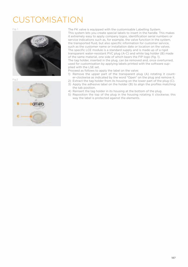
Fig. 1 The FK valve is equipped with the customisable Labelling System.This system lets you create special labels to insert in the handle. This makes it extremely easy to apply company logos, identification serial numbers or service indications such as, for example, the valve function in the system, the transported fluid, but also specific information for customer service, such as the customer name or installation date or location on the valves.The specific LCE module is a standard supply and is made up of a rigid transparent water-resistant PVC plug (A-C) and white tag holder (B) made of the same material, one side of which bears the FIP logo (fig. 1).The tag holder, inserted in the plug, can be removed and, once overturned, used for customisation by applying labels printed with the software sup-plied with the LSE set.Proceed as follows to apply the label on the valve:1) Remove the upper part of the transparent plug (A) rotating it count-
er-clockwise as indicated by the word "Open" on the plug and remove it.2) Extract the tag holder from its housing on the lower part of the plug (C).3) Apply the adhesive label on the holder (B) to align the profiles matching
the tab position.4) Reinsert the tag holder in its housing at the bottom of the plug.5) Reposition the top of the plug in the housing rotating it clockwise; this
way the label is protected against the elements.
Fig.2
187
CUSTOMISATION
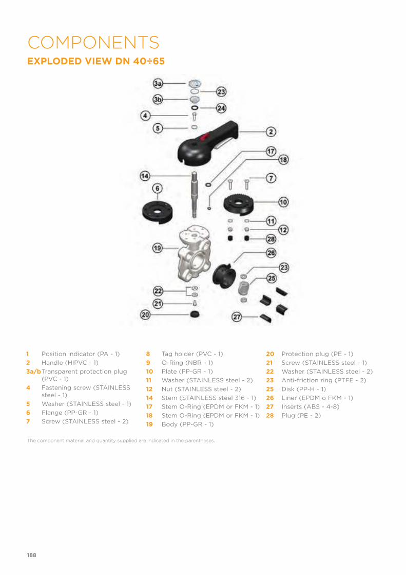
EXPLODED VIEW DN 40÷65
1 Position indicator (PA - 1)
2 Handle (HIPVC - 1)
3a/bTransparent protection plug (PVC - 1)
4 Fastening screw (STAINLESS steel - 1)
5 Washer (STAINLESS steel - 1)
6 Flange (PP-GR - 1)
7 Screw (STAINLESS steel - 2)
8 Tag holder (PVC - 1)
9 O-Ring (NBR - 1)
10 Plate (PP-GR - 1)
11 Washer (STAINLESS steel - 2)
12 Nut (STAINLESS steel - 2)
14 Stem (STAINLESS steel 316 - 1)
17 Stem O-Ring (EPDM or FKM - 1)
18 Stem O-Ring (EPDM or FKM - 1)
19 Body (PP-GR - 1)
20 Protection plug (PE - 1)
21 Screw (STAINLESS steel - 1)
22 Washer (STAINLESS steel - 2)
23 Anti-friction ring (PTFE - 2)
25 Disk (PP-H - 1)
26 Liner (EPDM o FKM - 1)
27 Inserts (ABS - 4-8)
28 Plug (PE - 2)
The component material and quantity supplied are indicated in the parentheses.
188
COMPONENTS
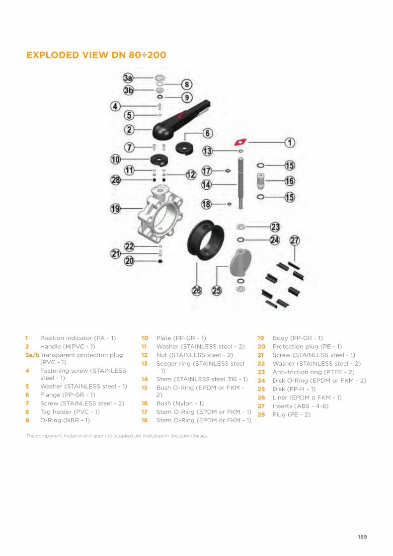
EXPLODED VIEW DN 80÷200
1 Position indicator (PA - 1)
2 Handle (HIPVC - 1)
3a/bTransparent protection plug (PVC - 1)
4 Fastening screw (STAINLESS steel - 1)
5 Washer (STAINLESS steel - 1)
6 Flange (PP-GR - 1)
7 Screw (STAINLESS steel - 2)
8 Tag holder (PVC - 1)
9 O-Ring (NBR - 1)
10 Plate (PP-GR - 1)
11 Washer (STAINLESS steel - 2)
12 Nut (STAINLESS steel - 2)
13 Seeger ring (STAINLESS steel - 1)
14 Stem (STAINLESS steel 316 - 1)
15 Bush O-Ring (EPDM or FKM - 2)
16 Bush (Nylon - 1)
17 Stem O-Ring (EPDM or FKM - 1)
18 Stem O-Ring (EPDM or FKM - 1)
19 Body (PP-GR - 1)
20 Protection plug (PE - 1)
21 Screw (STAINLESS steel - 1)
22 Washer (STAINLESS steel - 2)
23 Anti-friction ring (PTFE - 2)
24 Disk O-Ring (EPDM or FKM - 2)
25 Disk (PP-H - 1)
26 Liner (EPDM o FKM - 1)
27 Inserts (ABS - 4-8)
28 Plug (PE - 2)
The component material and quantity supplied are indicated in the parentheses.
189

EXPLODED VIEW DN 250÷300
1 Body (PP-GR - 1)
2 Washer (STAINLESS steel - 1)
3 Bush (PP - 1)
4 Bush O-Ring (EPDM or FKM - 4)
5 Bush (PP - 2)
6 Washer (PTFE - 2)
7 Liner (EPDM o FKM - 1)
8 Anti-friction ring (PTFE - 2)
9 Disk O-Ring (EPDM or FKM - 2)
10 Disk (PP-H - 1)
11 Washer (STAINLESS steel - 2)
12 Washer (STAINLESS steel - 1)
13 Protection plug (PE - 1)
14 Screw (STAINLESS steel - 1)
15 Washer (STAINLESS steel - 1)
16 Stem (STAINLESS steel 316 - 1)
17 Stem O-Ring (EPDM or FKM - 2)
18 Seeger ring (STAINLESS steel - 1)
19 O-Ring (EPDM or FKM - 2)
The component material and quantity supplied are indicated in the parentheses.
190
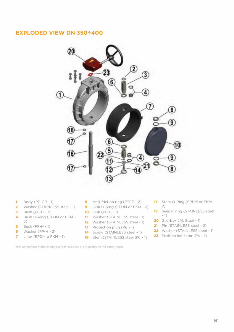
EXPLODED VIEW DN 350÷400
1 Body (PP-GR - 1)
2 Washer (STAINLESS steel - 1)
3 Bush (PP-H - 1)
4 Bush O-Ring (EPDM or FKM - 6)
5 Bush (PP-H - 1)
6 Washer (PP-H - 2)
7 Liner (EPDM o FKM - 1)
8 Anti-friction ring (PTFE - 2)
9 Disk O-Ring (EPDM or FKM - 2)
10 Disk (PP-H - 1)
11 Washer (STAINLESS steel - 1)
12 Washer (STAINLESS steel - 1)
13 Protection plug (PE - 1)
14 Screw (STAINLESS steel - 1)
16 Stem (STAINLESS steel 316 - 1)
17 Stem O-Ring (EPDM or FKM - 2)
18 Seeger ring (STAINLESS steel - 1)
20 Gearbox (Al, Steel - 1)
21 Pin (STAINLESS steel - 2)
22 Washer (STAINLESS steel - 1)
23 Position indicator (PA - 1)
The component material and quantity supplied are indicated in the parentheses.
191
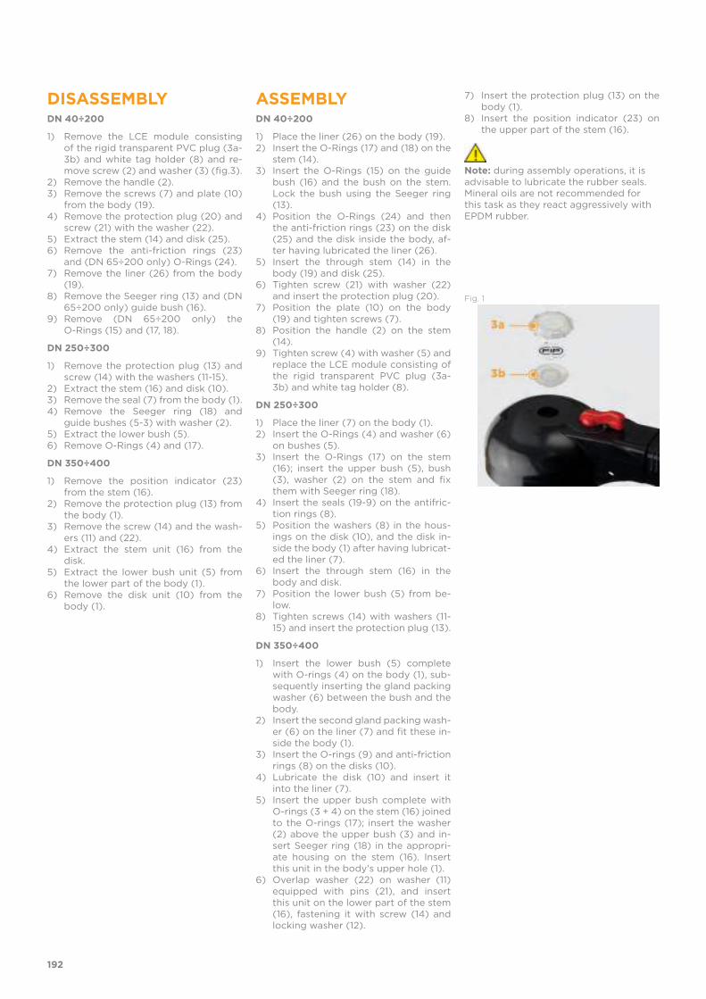
DISASSEMBLYDN 40÷200
1) Remove the LCE module consisting of the rigid transparent PVC plug (3a-3b) and white tag holder (8) and re-move screw (2) and washer (3) (fig.3).
2) Remove the handle (2).3) Remove the screws (7) and plate (10)
from the body (19).4) Remove the protection plug (20) and
screw (21) with the washer (22).5) Extract the stem (14) and disk (25).6) Remove the anti-friction rings (23)
and (DN 65÷200 only) O-Rings (24).7) Remove the liner (26) from the body
(19).8) Remove the Seeger ring (13) and (DN
65÷200 only) guide bush (16).9) Remove (DN 65÷200 only) the
O-Rings (15) and (17, 18).
DN 250÷300
1) Remove the protection plug (13) and screw (14) with the washers (11-15).
2) Extract the stem (16) and disk (10).3) Remove the seal (7) from the body (1).4) Remove the Seeger ring (18) and
guide bushes (5-3) with washer (2).5) Extract the lower bush (5).6) Remove O-Rings (4) and (17).
DN 350÷400
1) Remove the position indicator (23) from the stem (16).
2) Remove the protection plug (13) from the body (1).
3) Remove the screw (14) and the wash-ers (11) and (22).
4) Extract the stem unit (16) from the disk.
5) Extract the lower bush unit (5) from the lower part of the body (1).
6) Remove the disk unit (10) from the body (1).
ASSEMBLYDN 40÷200
1) Place the liner (26) on the body (19).2) Insert the O-Rings (17) and (18) on the
stem (14).3) Insert the O-Rings (15) on the guide
bush (16) and the bush on the stem. Lock the bush using the Seeger ring (13).
4) Position the O-Rings (24) and then the anti-friction rings (23) on the disk (25) and the disk inside the body, af-ter having lubricated the liner (26).
5) Insert the through stem (14) in the body (19) and disk (25).
6) Tighten screw (21) with washer (22) and insert the protection plug (20).
7) Position the plate (10) on the body (19) and tighten screws (7).
8) Position the handle (2) on the stem (14).
9) Tighten screw (4) with washer (5) and replace the LCE module consisting of the rigid transparent PVC plug (3a-3b) and white tag holder (8).
DN 250÷300
1) Place the liner (7) on the body (1).2) Insert the O-Rings (4) and washer (6)
on bushes (5).3) Insert the O-Rings (17) on the stem
(16); insert the upper bush (5), bush (3), washer (2) on the stem and fix them with Seeger ring (18).
4) Insert the seals (19-9) on the antifric-tion rings (8).
5) Position the washers (8) in the hous-ings on the disk (10), and the disk in-side the body (1) after having lubricat-ed the liner (7).
6) Insert the through stem (16) in the body and disk.
7) Position the lower bush (5) from be-low.
8) Tighten screws (14) with washers (11-15) and insert the protection plug (13).
DN 350÷400
1) Insert the lower bush (5) complete with O-rings (4) on the body (1), sub-sequently inserting the gland packing washer (6) between the bush and the body.
2) Insert the second gland packing wash-er (6) on the liner (7) and fit these in-side the body (1).
3) Insert the O-rings (9) and anti-friction rings (8) on the disks (10).
4) Lubricate the disk (10) and insert it into the liner (7).
5) Insert the upper bush complete with O-rings (3 + 4) on the stem (16) joined to the O-rings (17); insert the washer (2) above the upper bush (3) and in-sert Seeger ring (18) in the appropri-ate housing on the stem (16). Insert this unit in the body's upper hole (1).
6) Overlap washer (22) on washer (11) equipped with pins (21), and insert this unit on the lower part of the stem (16), fastening it with screw (14) and locking washer (12).
7) Insert the protection plug (13) on the body (1).
8) Insert the position indicator (23) on the upper part of the stem (16).
Note: during assembly operations, it is advisable to lubricate the rubber seals. Mineral oils are not recommended for this task as they react aggressively with EPDM rubber.
Fig. 1
192
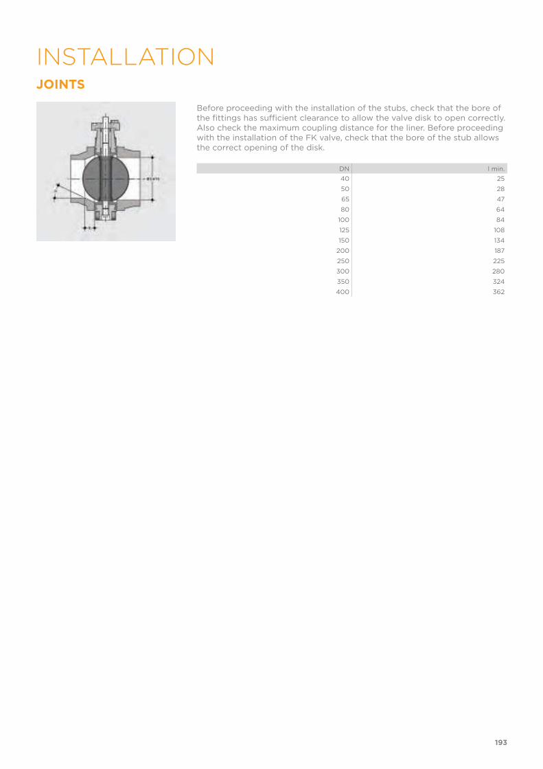
JOINTS
Before proceeding with the installation of the stubs, check that the bore of the fittings has sufficient clearance to allow the valve disk to open correctly. Also check the maximum coupling distance for the liner. Before proceeding with the installation of the FK valve, check that the bore of the stub allows the correct opening of the disk.
DN l min.
40 25
50 28
65 47
80 64
100 84
125 108
150 134
200 187
250 225
300 280
350 324
400 362
193
INSTALLATION
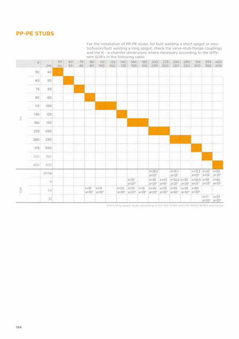
PP-PE STUBS
For the installation of PP-PE stubs, for butt welding a short spigot or elec-trofusion/butt welding a long spigot, check the valve-stub-flange couplings and the K - a chamfer dimensions where necessary according to the diffe-rent SDR's in the following table.
Short/long spigot stubs according to EN ISO 15494 and DIN 16962/16963 and flange
194
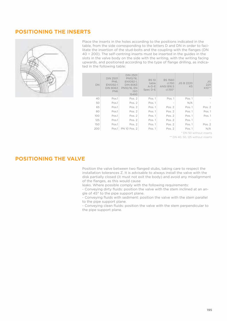
POSITIONING THE INSERTS
Place the inserts in the holes according to the positions indicated in the table, from the side corresponding to the letters D and DN in order to faci-litate the insertion of the stud-bolts and the coupling with the flanges (DN 40 ÷ 200). The self-centring inserts must be inserted in the guides in the slots in the valve body on the side with the writing, with the writing facing upwards, and positioned according to the type of flange drilling, as indica-ted in the following table:
DN
DIN 2501 PN6,
EN1092-1DIN 8063
PN6
DIN 2501 PN10/16,
EN1092-1, DIN 8063
PN10/16, EN ISO
15493
BS 10 table A-D-E
Spec D-E
BS 1560 cl.150
ANSI B16.5 cl.150*
JIS B 2220 K5
JIS 2211
K10**
40 Pos.1 Pos. 2 Pos. 1 Pos. 1 Pos. 1 -
50 Pos.1 Pos. 2 Pos. 1 - N/A -
65 Pos.1 Pos. 2 Pos. 1 Pos. 2 Pos. 1 Pos. 2
80 Pos.1 Pos. 2 Pos. 1 Pos. 2 Pos. 1 Pos. 1
100 Pos.1 Pos. 2 Pos. 1 Pos. 2 Pos. 1 Pos. 1
125 Pos.1 Pos. 2 Pos. 1 Pos. 2 Pos. 1 -
150 Pos.1 Pos. 2 Pos. 1 Pos. 2 Pos. 1 Pos. 2
200 Pos.1 PN 10 Pos. 2 Pos. 1 Pos. 2 Pos. 1 N/A
* DN 50 without inserts
** DN 40, 50, 125 without inserts
POSITIONING THE VALVE
Position the valve between two flanged stubs, taking care to respect the installation tolerances Z. It is advisable to always install the valve with the disk partially closed (it must not exit the body) and avoid any misalignment of the flanges, as this would causeleaks. Where possible comply with the following requirements:- Conveying dirty fluids: position the valve with the stem inclined at an an-gle of 45° to the pipe support plane.- Conveying fluids with sediment: position the valve with the stem parallel to the pipe support plane.- Conveying clean fluids: position the valve with the stem perpendicular to the pipe support plane.
195

TIGHTENING THE STUD-BOLTS
Before tightening the stud-bolts, it is advisable to open the disk in order to prevent damage to the seal. Tighten the stud-bolts in a uniform manner, in the order indicated in the figure, to the nominal operating torque value in-dicated in the table. The stud-bolts do not need to be excessively tightened in order to produce a perfect hydraulic seal. Overtightening could adversely affect the operating torque of the valve.
DN L min. *Nm
40 M16 x 150 9
50 M16 x 150 12
65 M16 x 170 15
80 M16 x 180 18
100 M16 x 180 20
125 M16 x 210 35
150 M20 x 240 40
200 M20 x 260 55
250 M20 x 310 70
300 M20 x 340 70
350 M20 x 360 75
400 M24 x 420 75
* Tightening torques for nuts and bolts on couplings with backing rings.
Values required to obtain the hydraulic test seal (1.5xPN at 20°C) (new or lubricated nuts and
bolts)
HANDLE LOCK
Thanks to the multifunctional handle and the red manoeuvre button on the lever, you can perform a 0°-90° operation and a graduated operation by means of the 10 intermediate positions and a stop lock: the handle can be locked in each of the 10 positions bysimply pressing the Free-lock button. Alock can also be installed on the handle to protect the system against tampering.The valve is two-way and can be installed in any position. It can also be installed at end line or tank.
196

WARNINGS
Make sure that the valves installed on the system are suitably supported for their weight.Always avoid sudden closing manoeuvres and protect the valve from ac-cidental operations. To this end, it is advisable to install a reduction gear, available on request.In the case of dirty fluids or those with sediments, install the valve inclined as shown in the figure.
197


DK DN 15÷65
PP-H
DIALOCK® 2-way diaphragm valve

DK DN 15÷65
DIALOCK® 2-WAY DIAPHRAGM VALVE
• Connection system for solvent weld, threaded and flanged joints• Optimised fluid dynamic design: maximum output flow rate thanks to the
optimised efficiency of the fluid dynamics that characterise the new inter-nal geometry of the body
• Internal components in metal, totally isolated from the fluid and external environment
• Modularity of the range: only 2 handwheel and 4 diaphragm and bonnet sizes for 7 different valve sizes
• Non-rising handwheel that stays at the same height during rotation, equipped with a graduated optical indicator protected by a transparent PVC cap with seal O-Ring
• Bonnet fastening screws in stainless steel protected against the external environment by PE plugs. Absence of metal parts exposed to the external environment to prevent any risk of corrosion
• New flanged bodies: the new bodies, characterised by a monolithic flanged structure, are available in PVC-U, PVC-C, PP-H and PVDF. This design, free from body and flange joints, greatly reduces mechanical stress and increases system performance.
• CDSA (Circular Diaphragm Sealing Angle) system that, thanks to the uniform distribution of shutter pressure on the diaphragm seal, offers the following advantages:
− reduction in the tightening torque of the screws fixing the actuator to the valve body − reduced mechanical stress on all valve components (actuator, body and diaphragm) − easy to clean valve interior − low risk of the accumulation of deposits, contamination or damage to the diaphragm due to crystallisation − operating torque reduction
The DK DIALOCK® diaphragm valve is particularly suitable for shutting off and regulating abrasive or dirty fluids. The new internal geometry of the body increases flow coefficient, reduce pressure drop and allows a sensitive and precise adjustment along the entire stroke of the shutter. The DK is extremely compact and very light. The innovative handwheel is equipped with a patented immediate and ergonomic operating locking device that allows it to be adjusted and locked in any position.
Technical specifications
Construction Diaphragm valve with maximized flow rate and DIALOCK® lockable handwheel
Size range DN 15 ÷ 65
Nominal pressure PN 10 with water at 20° C
Temperature range 0 °C ÷ 100 °C
Coupling standards Welding: EN ISO 15494. Can be coupled to pipes according to EN ISO 15494.
Thread: ISO 228-1, DIN 2999.
Flanging system: ISO 7005-1, EN ISO 1092-1, EN 15494, EN 558-1, DIN 2501, ANSI B.16.5 cl.150
Reference standards Construction criteria: EN ISO 16138, EN ISO 15494
Test methods and requirements: ISO 9393
Installation criteria: DVS 2202-1, DVS 2207-11, DVS 2208-1, UNI 11318
Valve material Body: PP-HBonnet and handwheel: PP-GRPosition indicator cap: PVC
Seal material EPDM, FKM, PTFE
Control options Manual control; pneumatic actuator
200
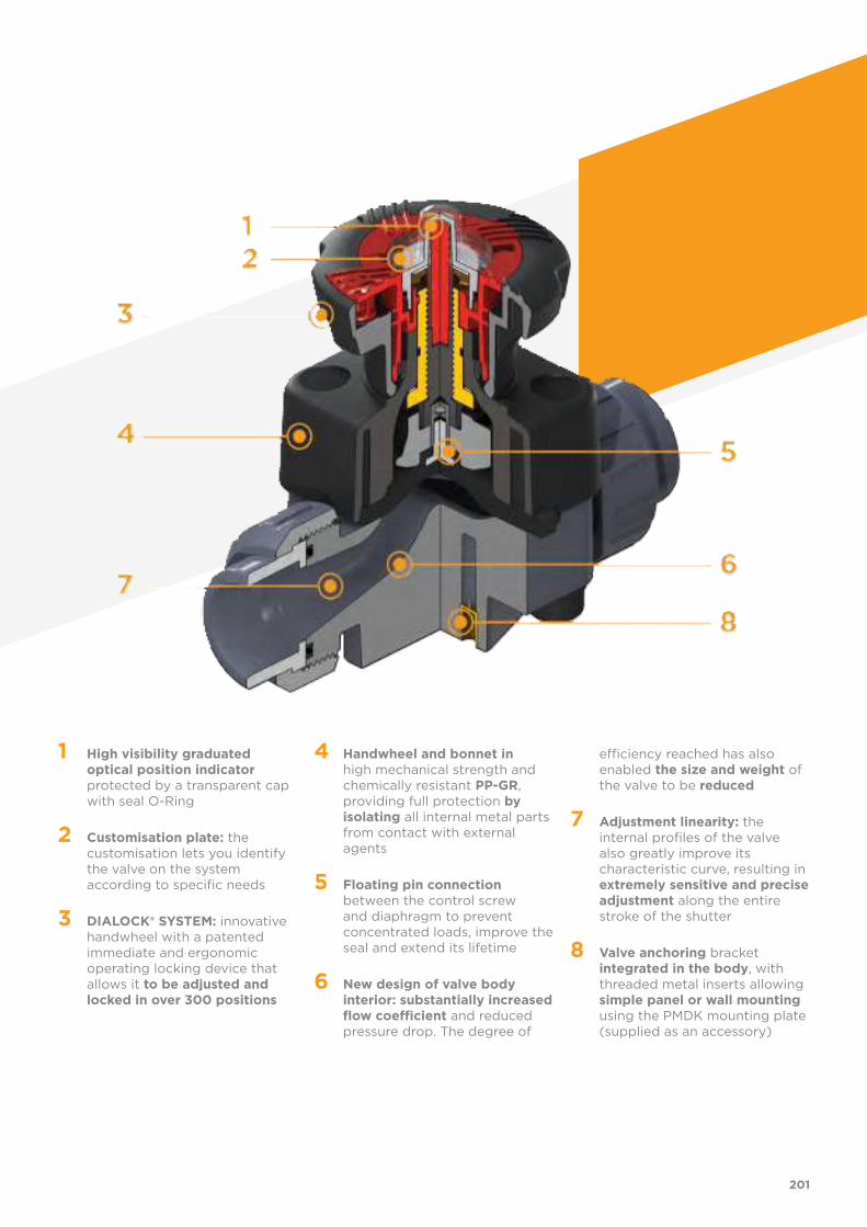
1 High visibility graduated optical position indicator protected by a transparent cap with seal O-Ring
2 Customisation plate: the customisation lets you identify the valve on the system according to specific needs
3 DIALOCK® SYSTEM: innovative handwheel with a patented immediate and ergonomic operating locking device that allows it to be adjusted and locked in over 300 positions
4 Handwheel and bonnet in high mechanical strength and chemically resistant PP-GR, providing full protection by isolating all internal metal parts from contact with external agents
5 Floating pin connection between the control screw and diaphragm to prevent concentrated loads, improve the seal and extend its lifetime
6 New design of valve body interior: substantially increased flow coefficient and reduced pressure drop. The degree of
efficiency reached has also enabled the size and weight of the valve to be reduced
7 Adjustment linearity: the internal profiles of the valve also greatly improve its characteristic curve, resulting in extremely sensitive and precise adjustment along the entire stroke of the shutter
8 Valve anchoring bracket integrated in the body, with threaded metal inserts allowing simple panel or wall mounting using the PMDK mounting plate (supplied as an accessory)
201
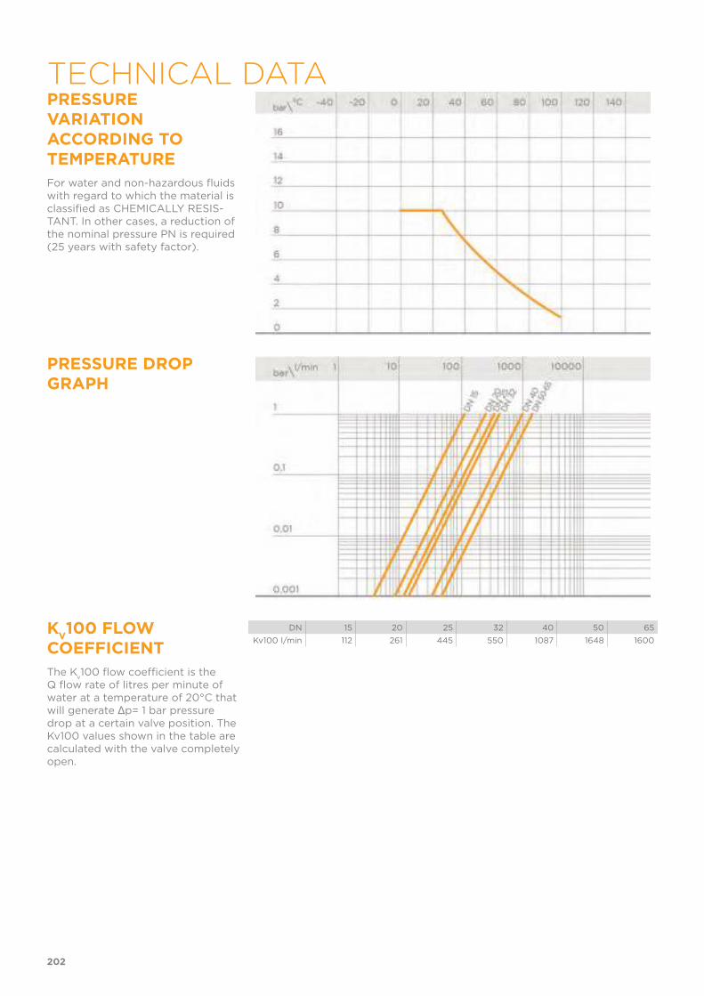
PRESSURE VARIATION ACCORDING TO TEMPERATURE
For water and non-hazardous fluids with regard to which the material is classified as CHEMICALLY RESIS-TANT. In other cases, a reduction of the nominal pressure PN is required (25 years with safety factor).
PRESSURE DROP GRAPH
KV100 FLOW
COEFFICIENT
The Kv100 flow coefficient is the
Q flow rate of litres per minute of water at a temperature of 20°C that will generate Δp= 1 bar pressure drop at a certain valve position. The Kv100 values shown in the table are calculated with the valve completely open.
DN 15 20 25 32 40 50 65
Kv100 l/min 112 261 445 550 1087 1648 1600
202
TECHNICAL DATA

RELATIVE FLOW COEFFICIENT GRAPH
The relative flow coefficient is the flow rate through the valve as a function of the degree of valve opening.Horizontal axis: Opening percentage of the valve Vertical axis: Relative flow coeffi-cient
The information in this leaflet is provided in good faith. No liability will be accepted concerning technical data that is not directly covered by recogni-
sed international standards. FIP reserves the right to carry out any modification. Products must be installed and maintained by qualified personnel.
203
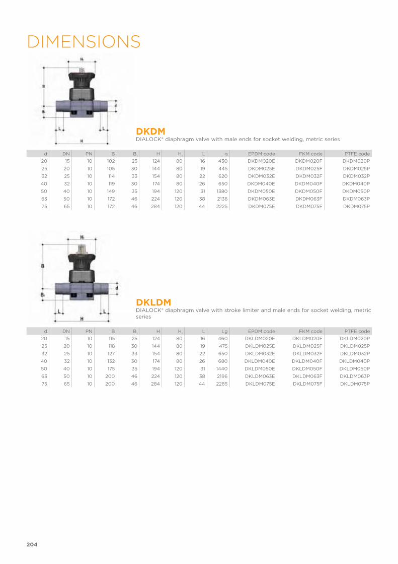
204
DIMENSIONS
DKDMDIALOCK® diaphragm valve with male ends for socket welding, metric series
d DN PN B B1
H H1
L g EPDM code FKM code PTFE code
20 15 10 102 25 124 80 16 430 DKDM020E DKDM020F DKDM020P
25 20 10 105 30 144 80 19 445 DKDM025E DKDM025F DKDM025P
32 25 10 114 33 154 80 22 620 DKDM032E DKDM032F DKDM032P
40 32 10 119 30 174 80 26 650 DKDM040E DKDM040F DKDM040P
50 40 10 149 35 194 120 31 1380 DKDM050E DKDM050F DKDM050P
63 50 10 172 46 224 120 38 2136 DKDM063E DKDM063F DKDM063P
75 65 10 172 46 284 120 44 2225 DKDM075E DKDM075F DKDM075P
DKLDMDIALOCK® diaphragm valve with stroke limiter and male ends for socket welding, metric series
d DN PN B B1
H H1
L Lg EPDM code FKM code PTFE code
20 15 10 115 25 124 80 16 460 DKLDM020E DKLDM020F DKLDM020P
25 20 10 118 30 144 80 19 475 DKLDM025E DKLDM025F DKLDM025P
32 25 10 127 33 154 80 22 650 DKLDM032E DKLDM032F DKLDM032P
40 32 10 132 30 174 80 26 680 DKLDM040E DKLDM040F DKLDM040P
50 40 10 175 35 194 120 31 1440 DKLDM050E DKLDM050F DKLDM050P
63 50 10 200 46 224 120 38 2196 DKLDM063E DKLDM063F DKLDM063P
75 65 10 200 46 284 120 44 2285 DKLDM075E DKLDM075F DKLDM075P
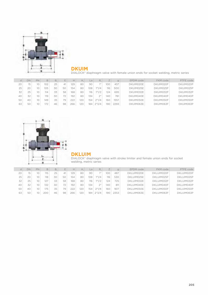
205
DKUIMDIALOCK® diaphragm valve with female union ends for socket welding, metric series
d DN PN B B1
E H H1
La R1
Z g EPDM code FKM code PTFE code
20 15 10 102 25 41 129 80 90 1" 100 457 DKUIM020E DKUIM020F DKUIM020P
25 20 10 105 30 50 154 80 108 1"1/4 116 500 DKUIM025E DKUIM025F DKUIM025P
32 25 10 114 33 58 168 80 116 1"1/2 124 695 DKUIM032E DKUIM032F DKUIM032P
40 32 10 119 30 72 192 80 134 2" 140 781 DKUIM040E DKUIM040F DKUIM040P
50 40 10 149 35 79 222 120 154 2"1/4 160 1557 DKUIM050E DKUIM050F DKUIM050P
63 50 10 172 46 98 266 120 184 2"3/4 190 2293 DKUIM063E DKUIM063F DKUIM063P
DKLUIMDIALOCK® diaphragm valve with stroke limiter and female union ends for socket welding, metric series
d DN PN B B1
E H H1
La R1
Z g EPDM code FKM code PTFE code
20 15 10 115 25 41 129 80 90 1" 100 487 DKLUIM020E DKLUIM020F DKLUIM020P
25 20 10 118 30 50 154 80 108 1"1/4 116 530 DKLUIM025E DKLUIM025F DKLUIM025P
32 25 10 127 33 58 168 80 116 1"1/2 124 725 DKLUIM032E DKLUIM032F DKLUIM032P
40 32 10 132 30 72 192 80 134 2" 140 811 DKLUIM040E DKLUIM040F DKLUIM040P
50 40 10 175 35 79 222 120 154 2"1/4 160 1617 DKLUIM050E DKLUIM050F DKLUIM050P
63 50 10 200 46 98 266 120 184 2"3/4 190 2353 DKLUIM063E DKLUIM063F DKLUIM063P

206
DKOMDIALOCK® diaphragm valve with flanged monolithic body, drilled PN10/16. Face to face according to EN 558-1
d DN PN B B1
F f H H1
Sp U g EPDM code FKM code PTFE code
20 15 10 102 25 65 14 130 80 4 13.5 817 DKOM020E DKOM020F DKOM020P
25 20 10 105 30 75 14 150 80 4 13.5 850 DKOM025E DKOM025F DKOM025P
32 25 10 114 33 85 14 160 80 4 13.5 892 DKOM032E DKOM032F DKOM032P
40 32 10 119 30 100 18 180 80 4 14 1005 DKOM040E DKOM040F DKOM040P
50 40 10 149 35 110 18 200 120 4 16 1771 DKOM050E DKOM050F DKOM050P
63 50 10 172 46 125 18 230 120 4 16 2453 DKOM063E DKOM063F DKOM063P
75 65 10 172 46 145 18 290 120 4 21 2997 DKOM075E DKOM075F DKOM075P
DKLOM version available on request
DKOAMDIALOCK® diaphragm valve with flanged monolithic body, drilled ANSI B16.5 cl. 150 #FF
d DN PN B B1
F f H H1
Sp U g EPDM code FKM code PTFE code
1/2" 15 10 102 25 60.3 14 108 80 4 13.5 817 DKOAM012E DKOAM012F DKOAM012P
3/4" 20 10 105 30 70 15.7 120 80 4 13.5 850 DKOAM034E DKOAM034F DKOAM034P
1" 25 10 114 33 80 15.7 131 80 4 13.5 892 DKOAM100E DKOAM100F DKOAM100P
1" 1/4 32 10 119 30 89 15.7 162 80 4 14 1005 DKOAM114E DKOAM114F DKOAM114P
1" 1/2 40 10 149 35 99 15.7 180 120 4 16 1771 DKOAM112E DKOAM112F DKOAM112P
2" 50 10 172 46 121 19 210 120 4 16 2453 DKOAM200E DKOAM200F DKOAM200P
2" 1/2 65 10 172 46 140 19 250 120 4 21 2997 DKOAM212E DKOAM212F DKOAM212P
DKLOAM version available on requestFor installation prior to october 2017 please contact Fip Technical Support

207
ACCESSORIESQ/BBM-LUnion end, long spigot, for butt welding for union BBM-L
d DN L H SDRPN10 code
SDR 11 - S 5
20 15 95 280 11 QBBML11020
25 20 95 298 11 QBBML11025
32 25 95 306 11 QBBML11032
40 32 95 324 11 QBBML11040
50 40 95 344 11 QBBML11050
63 50 95 374 11 QBBML11063
Q/BBM-CShort spigot PP-H end connectors for butt welding
d DN L H SDRPN10 code
SDR 11 - S 5
20 15 55 200 11 QBBMC11020
25 20 55 218 11 QBBMC11025
32 25 55 226 11 QBBMC11032
40 32 55 244 11 QBBMC11040
50 40 55 264 11 QBBMC11050
63 50 55 294 11 QBBMC11063
Q/BBE-LLong spigot PE100 end connectors for electrofusion or butt welding
d DN L H SDR Code
20 15 95 280 11 QBBEL11020
25 20 95 298 11 QBBEL11025
32 25 95 306 11 QBBEL11032
40 32 95 324 11 QBBEL11040
50 40 95 344 11 QBBEL11050
63 50 95 374 11 QBBEL11063
PMDKWall mounting plate
d DN A B C D F S Code
20 15 65 97 81 33 5,5 11 PMDK1
25 20 65 97 81 33 5,5 11 PMDK1
32 25 65 97 81 33 5,5 11 PMDK1
40 32 65 97 81 33 5,5 11 PMDK2
50 40 65 144 130 33 6,5 11 PMDK2
63 50 65 144 130 33 6,5 11 PMDK2
75 65 65 144 130 33 6,5 11 PMDK2

All valves, whether manual or actuated, must be adequately supported in many applications.The DK valve series is therefore provided with an integrated bracket that permits direct anchoring of the valve body without the need of other com-ponents.For wall or panel installation, dedicated PMDK mounting plates which are available as accessories can be used. These plates should be fastened to the valve before wall installation.PMDK plates also allow DK valve alignment with FIP ZIKM pipe clips.
d DN h I j
20 15 10 25 M6
25 20 10 25 M6
32 25 10 25 M6
40 32 10 25 M6
50 40 13 44,5 M8
63 50 13 44,5 M8
75 65 13 44,5 M8
208
FASTENING AND SUPPORTING

fig 1 The DIALOCK® DK DN 15÷65 valve can be customised using a customisation plate in white PVC.The customisation plate (B), housed in the transparent protection cap (A), can be removed and, once overturned, used for indicating identification serial numbers or service indications on the valves such as, for example, the valve function in the system, the conveyed fluid, but also specific informa-tion for customer service, such as the customer name or installation date or location on the valves. The waterproof transparent protection cap with seal O-Ring protects the customisation plate against deterioration.To access the customisation plate, make sure the handwheel is in the unlock position and proceed as follows:1) Turn the transparent protection cap anti-clockwise to limit stop (fig. 1)
and remove it by pulling it upwards and, if necessary, by inserting a screw-driver into the slot (C) to facilitate operation (fig. 2 ).
2) Remove the plate inside the transparent protection cap and customise it as required (fig. 3).
3) Re-assemble, making sure that the seal O-Ring of the transparent protec-tion cap remains in its seating (fig. 4).
fig 2
fig 3 fig 4
209
CUSTOMISATION
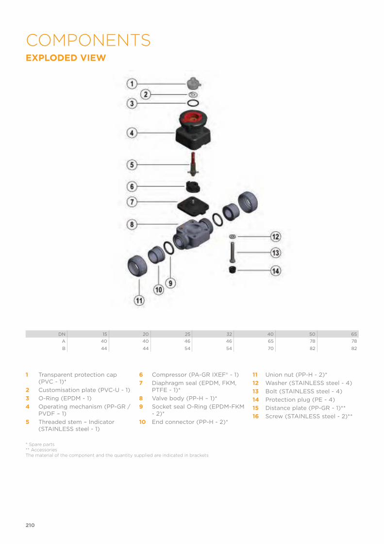
EXPLODED VIEW
DN 15 20 25 32 40 50 65
A 40 40 46 46 65 78 78
B 44 44 54 54 70 82 82
1 Transparent protection cap (PVC - 1)*
2 Customisation plate (PVC-U - 1)
3 O-Ring (EPDM - 1)
4 Operating mechanism (PP-GR / PVDF – 1)
5 Threaded stem – Indicator (STAINLESS steel - 1)
6 Compressor (PA-GR IXEF® - 1)
7 Diaphragm seal (EPDM, FKM, PTFE - 1)*
8 Valve body (PP-H – 1)*
9 Socket seal O-Ring (EPDM-FKM - 2)*
10 End connector (PP-H - 2)*
11 Union nut (PP-H - 2)*
12 Washer (STAINLESS steel - 4)
13 Bolt (STAINLESS steel - 4)
14 Protection plug (PE - 4)
15 Distance plate (PP-GR - 1)**
16 Screw (STAINLESS steel - 2)**
* Spare parts** AccessoriesThe material of the component and the quantity supplied are indicated in brackets
210
COMPONENTS
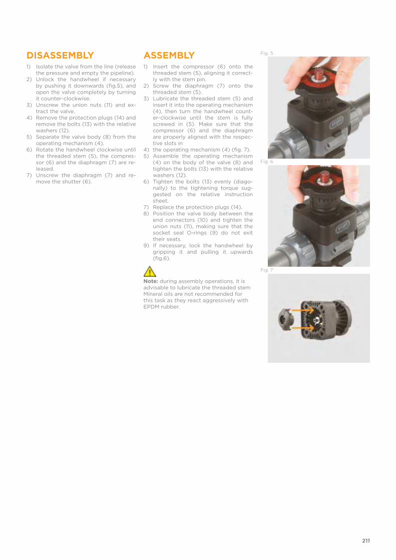
DISASSEMBLY1) Isolate the valve from the line (release
the pressure and empty the pipeline).2) Unlock the handwheel if necessary
by pushing it downwards (fig.5), and open the valve completely by turning it counter-clockwise.
3) Unscrew the union nuts (11) and ex-tract the valve.
4) Remove the protection plugs (14) and remove the bolts (13) with the relative washers (12).
5) Separate the valve body (8) from the operating mechanism (4).
6) Rotate the handwheel clockwise until the threaded stem (5), the compres-sor (6) and the diaphragm (7) are re-leased.
7) Unscrew the diaphragm (7) and re-move the shutter (6).
ASSEMBLY1) Insert the compressor (6) onto the
threaded stem (5), aligning it correct-ly with the stem pin.
2) Screw the diaphragm (7) onto the threaded stem (5).
3) Lubricate the threaded stem (5) and insert it into the operating mechanism (4), then turn the handwheel count-er-clockwise until the stem is fully screwed in (5). Make sure that the compressor (6) and the diaphragm are properly aligned with the respec-tive slots in
4) the operating mechanism (4) (fig. 7).5) Assemble the operating mechanism
(4) on the body of the valve (8) and tighten the bolts (13) with the relative washers (12).
6) Tighten the bolts (13) evenly (diago-nally) to the tightening torque sug-gested on the relative instruction sheet.
7) Replace the protection plugs (14).8) Position the valve body between the
end connectors (10) and tighten the union nuts (11), making sure that the socket seal O-rings (9) do not exit their seats.
9) If necessary, lock the handwheel by gripping it and pulling it upwards (fig.6).
Note: during assembly operations, it is advisable to lubricate the threaded stem Mineral oils are not recommended for this task as they react aggressively with EPDM rubber.
Fig. 5
Fig. 6
Fig. 7
211
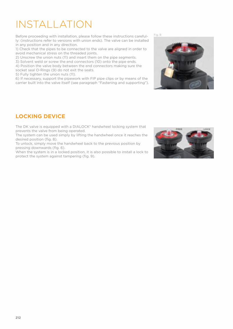
Before proceeding with installation, please follow these instructions careful-ly: (instructions refer to versions with union ends). The valve can be installed in any position and in any direction.1) Check that the pipes to be connected to the valve are aligned in order to avoid mechanical stress on the threaded joints.2) Unscrew the union nuts (11) and insert them on the pipe segments.3) Solvent weld or screw the end connectors (10) onto the pipe ends.4) Position the valve body between the end connectors making sure the socket seal O-Rings (9) do not exit the seats.5) Fully tighten the union nuts (11).6) If necessary, support the pipework with FIP pipe clips or by means of the carrier built into the valve itself (see paragraph “Fastening and supporting”).
Fig. 8
LOCKING DEVICE
The DK valve is equipped with a DIALOCK® handwheel locking system that prevents the valve from being operated.The system can be used simply by lifting the handwheel once it reaches the desired position (fig. 8).To unlock, simply move the handwheel back to the previous position by pressing downwards (fig. 6).When the system is in a locked position, it is also possible to install a lock to protect the system against tampering (fig. 9).
212
INSTALLATION

STROKE LIMITER
The DKL version of the diaphragm valve is equipped with a handwheel stroke control system which allows the minimum and maximum flows to be preset and preserves the diaphragm from excessive compression during closing operations.The system allows the valve stroke to be modified using the two indepen-dent adjusting screws, which determine the mechanical limits of the valve during opening and closing. The valve is sold with the stroke limiters posi-tioned so as not to limit the stroke bothduring closing and opening.To access and set the adjusting screws, remove the transparent protection cap (A) as previously described (see chapter “Customisation”).
Travel stop adjustment. Minimum flow rate or valve closed.1) Turn the handwheel clockwise until the desired minimum flow rate or the closed position is reached.2) Fully screw the nut (D) to limit stop, and lock it in this position by tighte-ning the locknut (E). If you want to exclude the stroke limiting function during closing, unscrew the nuts (D and E) completely. In this way, the valve will close completely.3) Re-assemble the transparent protection cap making sure that the seal O-Ring remains in its seating.
Stroke limiter adjustment. Maximum flow rate1) Turn the handwheel counter-clockwise until the desired maximum flow rate is reached.2) Turn the knob (F) counter-clockwise to limit stop. The plate shows the direction of rotation of the wheel to obtain a smaller or greater maximum flow rate. If it is not necessary to limit the opening stroke, turn the knob (F) clockwise several times. In this way, the valve will open completely.3) Re-assemble the transparent protection cap making sure that the seal O-Ring remains in its seating.
213

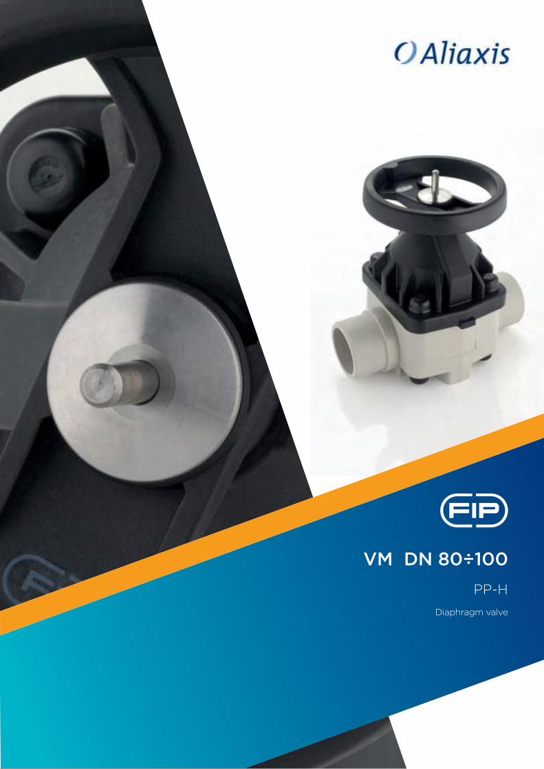
VM DN 80÷100
PP-H
Diaphragm valve
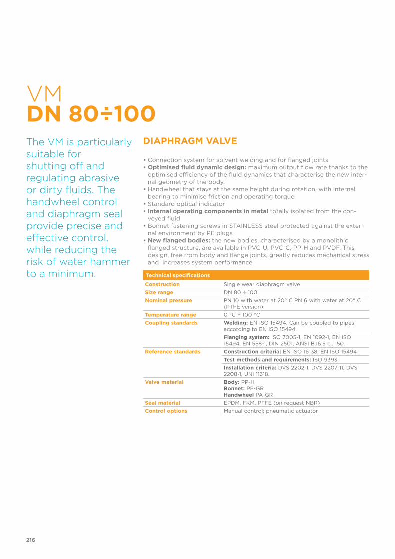
VM DN 80÷100
DIAPHRAGM VALVE
• Connection system for solvent welding and for flanged joints• Optimised fluid dynamic design: maximum output flow rate thanks to the
optimised efficiency of the fluid dynamics that characterise the new inter-nal geometry of the body.
• Handwheel that stays at the same height during rotation, with internal bearing to minimise friction and operating torque
• Standard optical indicator• Internal operating components in metal totally isolated from the con-
veyed fluid• Bonnet fastening screws in STAINLESS steel protected against the exter-
nal environment by PE plugs• New flanged bodies: the new bodies, characterised by a monolithic
flanged structure, are available in PVC-U, PVC-C, PP-H and PVDF. This design, free from body and flange joints, greatly reduces mechanical stress and increases system performance.
The VM is particularly suitable for shutting off and regulating abrasive or dirty fluids. The handwheel control and diaphragm seal provide precise and effective control, while reducing the risk of water hammer to a minimum. Technical specifications
Construction Single wear diaphragm valve
Size range DN 80 ÷ 100
Nominal pressure PN 10 with water at 20° C PN 6 with water at 20° C (PTFE version)
Temperature range 0 °C ÷ 100 °C
Coupling standards Welding: EN ISO 15494. Can be coupled to pipes according to EN ISO 15494.
Flanging system: ISO 7005-1, EN 1092-1, EN ISO 15494, EN 558-1, DIN 2501, ANSI B.16.5 cl. 150.
Reference standards Construction criteria: EN ISO 16138, EN ISO 15494
Test methods and requirements: ISO 9393
Installation criteria: DVS 2202-1, DVS 2207-11, DVS 2208-1, UNI 11318.
Valve material Body: PP-HBonnet: PP-GRHandwheel PA-GR
Seal material EPDM, FKM, PTFE (on request NBR)
Control options Manual control; pneumatic actuator
216
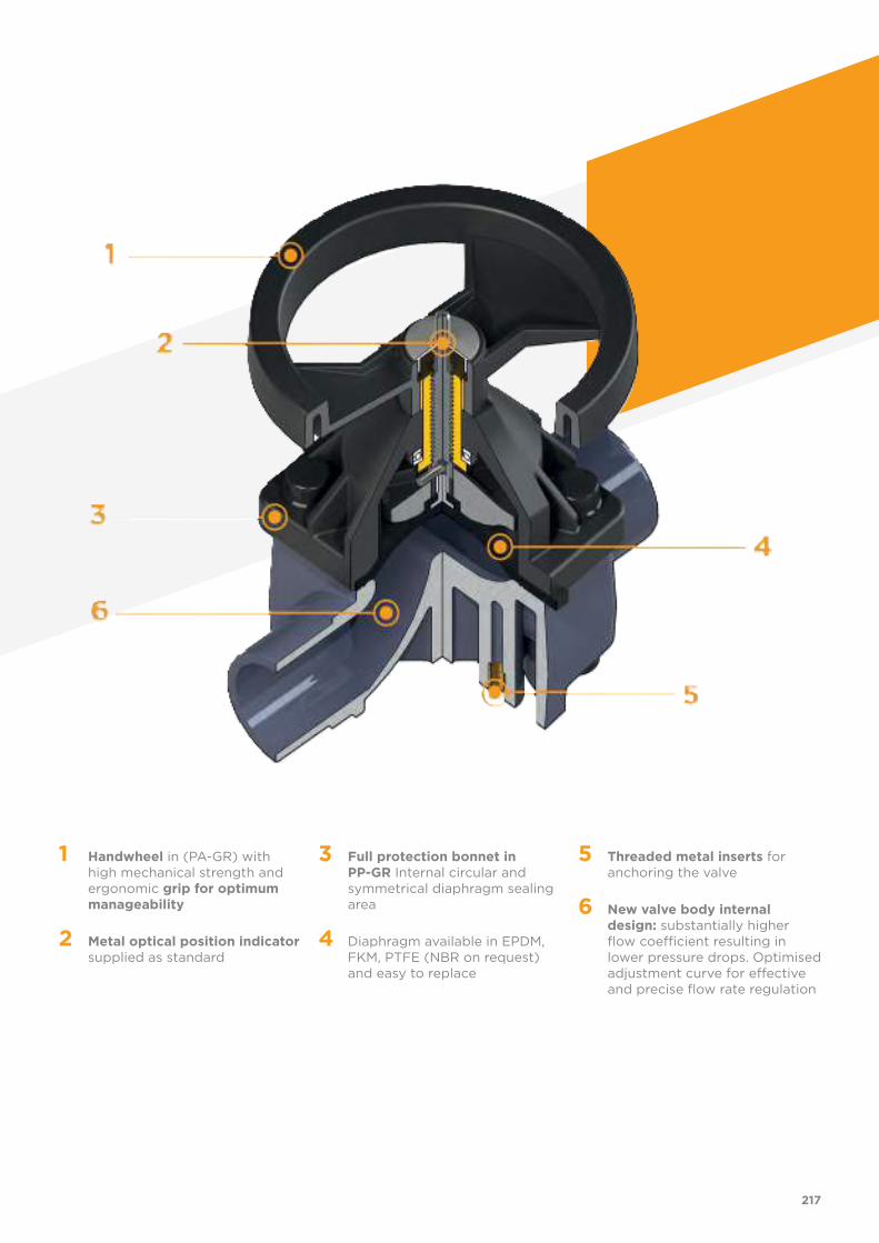
1 Handwheel in (PA-GR) with high mechanical strength and ergonomic grip for optimum manageability
2 Metal optical position indicator supplied as standard
3 Full protection bonnet in PP-GR Internal circular and symmetrical diaphragm sealing area
4 Diaphragm available in EPDM, FKM, PTFE (NBR on request) and easy to replace
5 Threaded metal inserts for anchoring the valve
6 New valve body internal design: substantially higher flow coefficient resulting in lower pressure drops. Optimised adjustment curve for effective and precise flow rate regulation
217
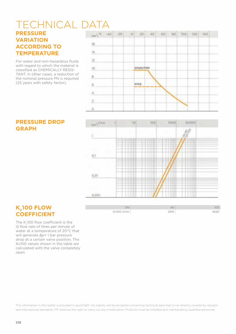
PRESSURE VARIATION ACCORDING TO TEMPERATURE
For water and non-hazardous fluids with regard to which the material is classified as CHEMICALLY RESIS-TANT. In other cases, a reduction of the nominal pressure PN is required (25 years with safety factor).
PRESSURE DROP GRAPH
KV100 FLOW
COEFFICIENT
The Kv100 flow coefficient is the
Q flow rate of litres per minute of water at a temperature of 20°C that will generate Δp= 1 bar pressure drop at a certain valve position. The Kv100 values shown in the table are calculated with the valve completely open.
DN 80 100
Kv100 l/min 2910 4620
The information in this leaflet is provided in good faith. No liability will be accepted concerning technical data that is not directly covered by recogni-
sed international standards. FIP reserves the right to carry out any modification. Products must be installed and maintained by qualified personnel.
218
TECHNICAL DATA
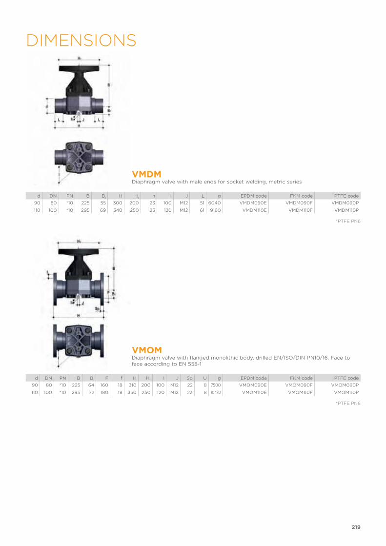
219
DIMENSIONS
VMDMDiaphragm valve with male ends for socket welding, metric series
d DN PN B B1
H H1
h I J L g EPDM code FKM code PTFE code
90 80 *10 225 55 300 200 23 100 M12 51 6040 VMDM090E VMDM090F VMDM090P
110 100 *10 295 69 340 250 23 120 M12 61 9160 VMDM110E VMDM110F VMDM110P
*PTFE PN6
VMOMDiaphragm valve with flanged monolithic body, drilled EN/ISO/DIN PN10/16. Face to face according to EN 558-1
d DN PN B B1
F f H H1
I J Sp U g EPDM code FKM code PTFE code
90 80 *10 225 64 160 18 310 200 100 M12 22 8 7500 VMOM090E VMOM090F VMOM090P
110 100 *10 295 72 180 18 350 250 120 M12 23 8 10480 VMOM110E VMOM110F VMOM110P
*PTFE PN6
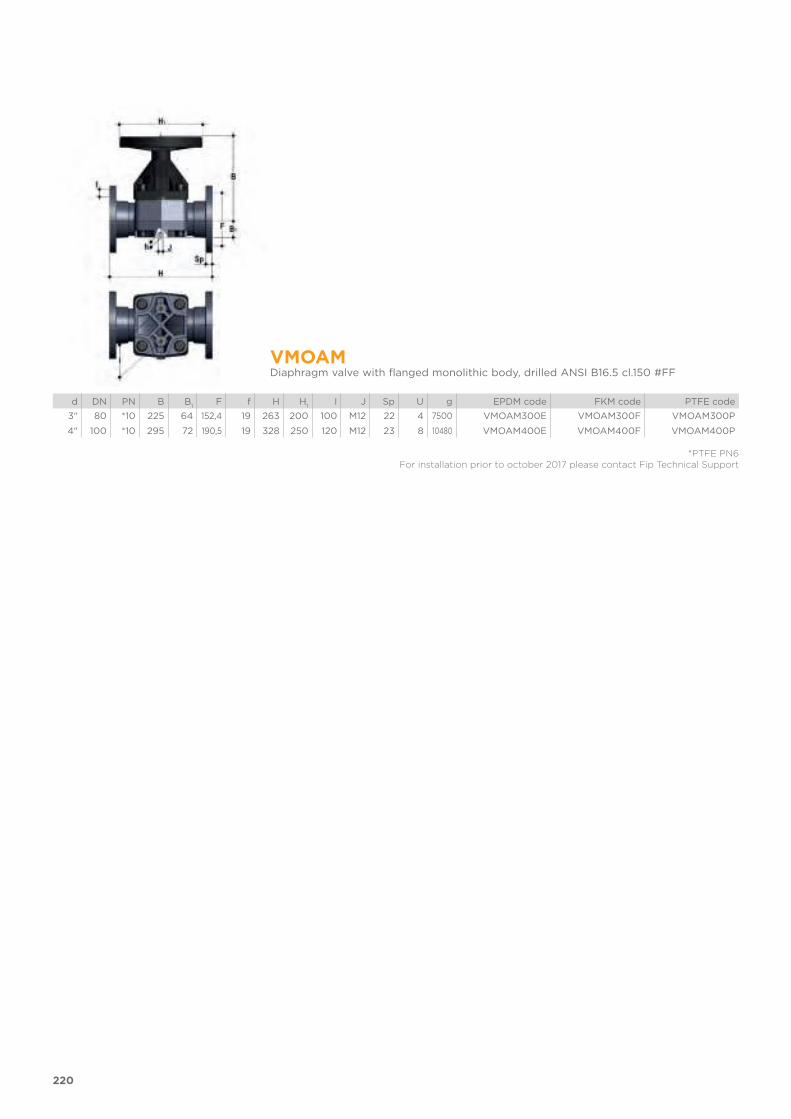
220
VMOAMDiaphragm valve with flanged monolithic body, drilled ANSI B16.5 cl.150 #FF
d DN PN B B1
F f H H1
I J Sp U g EPDM code FKM code PTFE code
3" 80 *10 225 64 152,4 19 263 200 100 M12 22 4 7500 VMOAM300E VMOAM300F VMOAM300P
4" 100 *10 295 72 190,5 19 328 250 120 M12 23 8 10480 VMOAM400E VMOAM400F VMOAM400P
*PTFE PN6For installation prior to october 2017 please contact Fip Technical Support
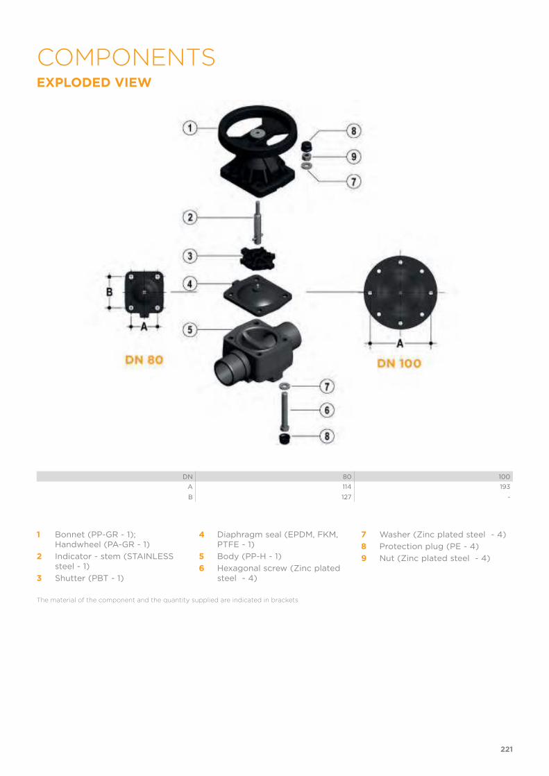
EXPLODED VIEW
DN 80 100
A 114 193
B 127 -
1 Bonnet (PP-GR - 1);Handwheel (PA-GR - 1)
2 Indicator - stem (STAINLESS steel - 1)
3 Shutter (PBT - 1)
4 Diaphragm seal (EPDM, FKM, PTFE - 1)
5 Body (PP-H - 1)
6 Hexagonal screw (Zinc plated steel - 4)
7 Washer (Zinc plated steel - 4)
8 Protection plug (PE - 4)
9 Nut (Zinc plated steel - 4)
The material of the component and the quantity supplied are indicated in brackets
221
COMPONENTS
DISASSEMBLYThe diaphragm constitutes the part of the valve more subject to mechani-cal and chemical stress from the fluid. Consequently, the condition of the diaphragm must be checked at regular intervals in accordance with the service conditions. To do this, it must be discon-nected from the handwheel and from the valve body.
1) Cut-off fluid upstream from the valve and make sure it is de-pressurised (downstream drain if necessary).
2) Unscrew the four screws (6) and sep-arate the body (5) from the internal components.
3) Unscrew the diaphragm (4) from the shutter (3). Rotate the handwheel clockwise to free the stem-shutter unit. Clean or replace the diaphragm, if necessary (4). If necessary, lubricate the stem (2).
ASSEMBLY1) Apply the shutter (3) to the stem (2),
ensuring the stem pin is positioned correctly.
2) Screw the diaphragm (4) onto the stem (2), taking care not to stretch it.
3) Open the valve.4) Place the bonnet-handwheel unit (1)
on the body (5) and join the two com-ponents with bolts.
5) Press the protection plugs into place (8).
222

The valve can be installed in any position and in any direction.When starting up the plant, make sure that there are no leaks from between the diaphragm and the valve body. If necessary, tighten the fastening screws (6).
WARNINGS Note: during assembly operations, it is advisable to lubricate the threaded stem. Mineral oils are not recommended for this task as they react aggressi-vely with EPDM rubber.Moreover, as the diaphragm seal is compressed between the body and the actuator, the valve body stud-bolts and nuts must be checked and tighte-ned, if necessary, prior to installation.
223
INSTALLATION

CM DN 12÷15
PP-H
Compact diaphragm valve
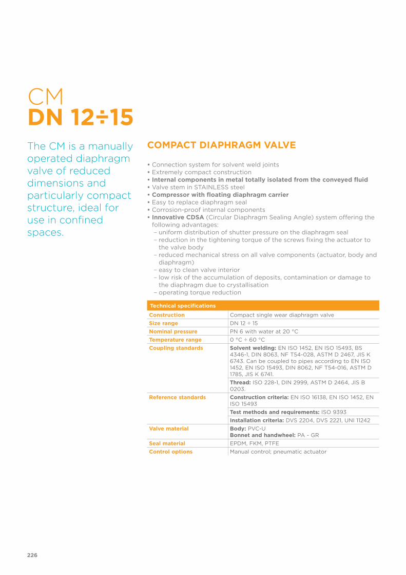
CM DN 12÷15
COMPACT DIAPHRAGM VALVE
• Connection system for solvent weld joints• Extremely compact construction• Internal components in metal totally isolated from the conveyed fluid• Valve stem in STAINLESS steel• Compressor with floating diaphragm carrier• Easy to replace diaphragm seal• Corrosion-proof internal components• Innovative CDSA (Circular Diaphragm Sealing Angle) system offering the
following advantages: − uniform distribution of shutter pressure on the diaphragm seal − reduction in the tightening torque of the screws fixing the actuator to the valve body − reduced mechanical stress on all valve components (actuator, body and diaphragm) − easy to clean valve interior − low risk of the accumulation of deposits, contamination or damage to the diaphragm due to crystallisation − operating torque reduction
The CM is a manually operated diaphragm valve of reduced dimensions and particularly compact structure, ideal for use in confined spaces.
Technical specifications
Construction Compact single wear diaphragm valve
Size range DN 12 ÷ 15
Nominal pressure PN 6 with water at 20 °C
Temperature range 0 °C ÷ 60 °C
Coupling standards Solvent welding: EN ISO 1452, EN ISO 15493, BS 4346-1, DIN 8063, NF T54-028, ASTM D 2467, JIS K 6743. Can be coupled to pipes according to EN ISO 1452, EN ISO 15493, DIN 8062, NF T54-016, ASTM D 1785, JIS K 6741.
Thread: ISO 228-1, DIN 2999, ASTM D 2464, JIS B 0203.
Reference standards Construction criteria: EN ISO 16138, EN ISO 1452, EN ISO 15493
Test methods and requirements: ISO 9393
Installation criteria: DVS 2204, DVS 2221, UNI 11242
Valve material Body: PVC-UBonnet and handwheel: PA - GR
Seal material EPDM, FKM, PTFE
Control options Manual control; pneumatic actuator
226
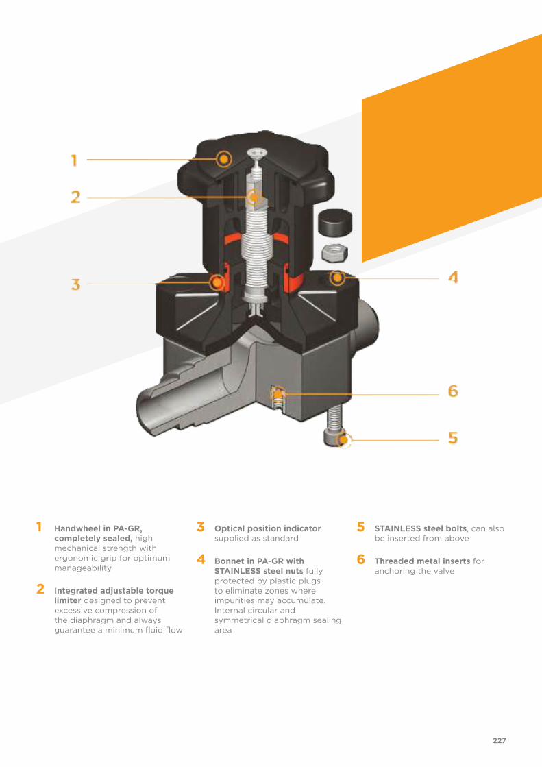
1 Handwheel in PA-GR, completely sealed, high mechanical strength with ergonomic grip for optimum manageability
2 Integrated adjustable torque limiter designed to prevent excessive compression of the diaphragm and always guarantee a minimum fluid flow
3 Optical position indicator supplied as standard
4 Bonnet in PA-GR with STAINLESS steel nuts fully protected by plastic plugs to eliminate zones where impurities may accumulate. Internal circular and symmetrical diaphragm sealing area
5 STAINLESS steel bolts, can also be inserted from above
6 Threaded metal inserts for anchoring the valve
227
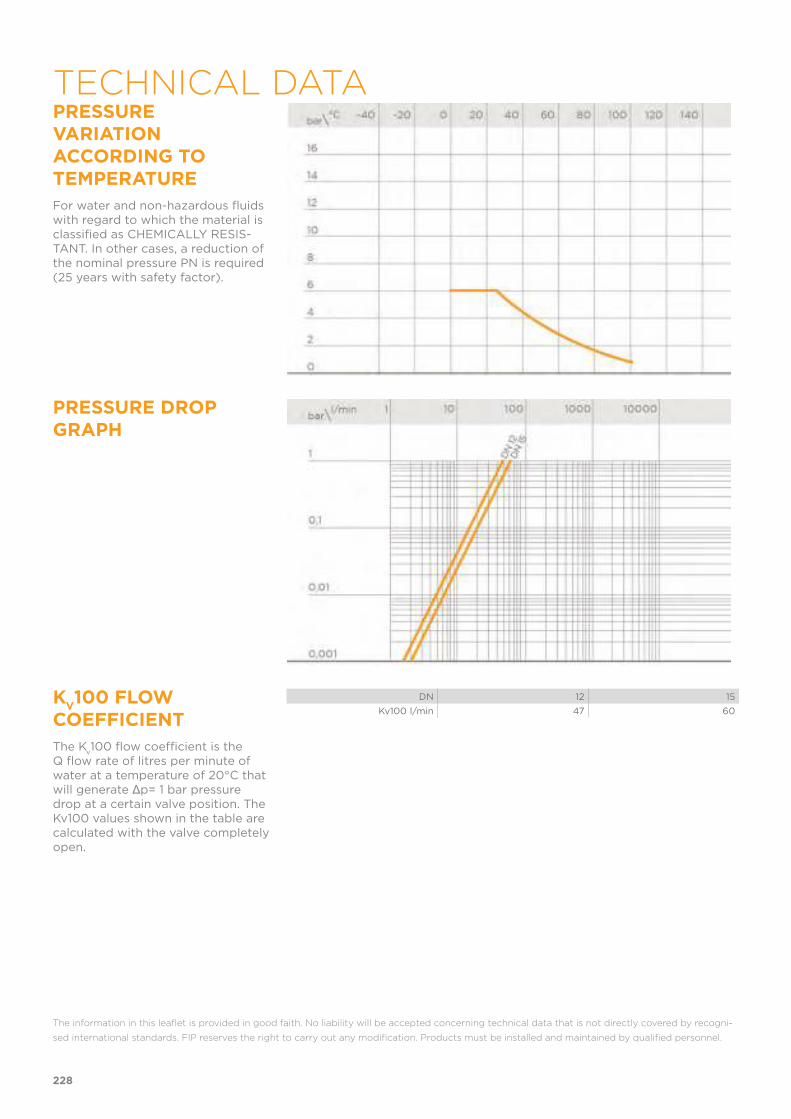
PRESSURE VARIATION ACCORDING TO TEMPERATURE
For water and non-hazardous fluids with regard to which the material is classified as CHEMICALLY RESIS-TANT. In other cases, a reduction of the nominal pressure PN is required (25 years with safety factor).
PRESSURE DROP GRAPH
KV100 FLOW
COEFFICIENT
The Kv100 flow coefficient is the
Q flow rate of litres per minute of water at a temperature of 20°C that will generate Δp= 1 bar pressure drop at a certain valve position. The Kv100 values shown in the table are calculated with the valve completely open.
DN 12 15
Kv100 l/min 47 60
The information in this leaflet is provided in good faith. No liability will be accepted concerning technical data that is not directly covered by recogni-
sed international standards. FIP reserves the right to carry out any modification. Products must be installed and maintained by qualified personnel.
228
TECHNICAL DATA
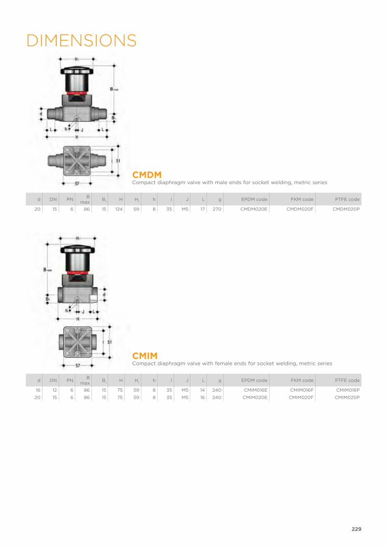
229
DIMENSIONS
CMDMCompact diaphragm valve with male ends for socket welding, metric series
d DN PNB
maxB
1H H
1h I J L g EPDM code FKM code PTFE code
20 15 6 86 15 124 59 8 35 M5 17 270 CMDM020E CMDM020F CMDM020P
CMIMCompact diaphragm valve with female ends for socket welding, metric series
d DN PNB
maxB
1H H
1h I J L g EPDM code FKM code PTFE code
16 12 6 86 15 75 59 8 35 M5 14 240 CMIM016E CMIM016F CMIM016P
20 15 6 86 15 75 59 8 35 M5 16 240 CMIM020E CMIM020F CMIM020P
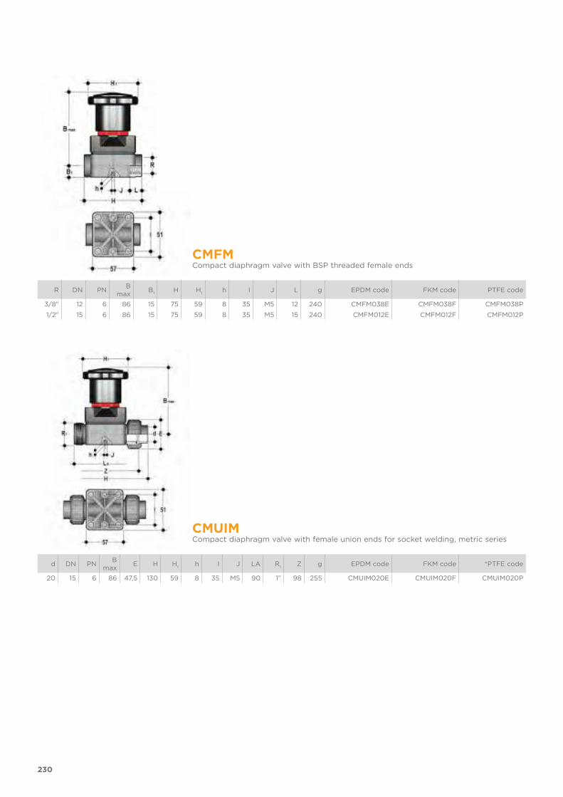
230
CMFMCompact diaphragm valve with BSP threaded female ends
R DN PNB
maxB
1H H
1h I J L g EPDM code FKM code PTFE code
3/8” 12 6 86 15 75 59 8 35 M5 12 240 CMFM038E CMFM038F CMFM038P
1/2” 15 6 86 15 75 59 8 35 M5 15 240 CMFM012E CMFM012F CMFM012P
CMUIMCompact diaphragm valve with female union ends for socket welding, metric series
d DN PNB
maxE H H
1h I J LA R
1Z g EPDM code FKM code *PTFE code
20 15 6 86 47,5 130 59 8 35 M5 90 1” 98 255 CMUIM020E CMUIM020F CMUIM020P

EXPLODED VIEW
1 Body (PP-H- 1)
2 Diaphragm seal (EPDM, FKM, PTFE - 1)
5 Fastening screw (STAINLESS steel - 4)
6 Washer (STAINLESS steel - 4)
7 Shutter (PA-GR - 1)
8 Nut (STAINLESS steel - 1)
9 Stem (STAINLESS steel - 1)
10 Bonnet (PA-GR - 1)
13 Nut (STAINLESS steel - 4)
14 Protection plug (POM - 4)
15 Optical position indicator (PVDF - 1)
22 O-Ring (NBR - 1)
23 Handwheel (PA-GR - 1)
24 O-Ring (NBR - 1)
25 Bonnet (PA-GR - 1)
26 Fastening screw (STAINLESS steel - 1)
The material of the component and the quantity supplied are indicated between brackets
231
COMPONENTS
DISASSEMBLYIf the valve is already installed on the line, shut-off the fluid flow upstream and make sure that there is no pressure. If ne-cessary, fully drain the system downstre-am. If there are hazardous fluids present, drain and ventilate the valve.
The diaphragm constitutes the part of the valve more subject to mechani-cal and chemical stress from the fluid. Consequently, the condition of the diaphragm must be checked at regular intervals in accordance with the service conditions. To do this, it must be
disconnected from the handwheel and from the valve body.
1) Unscrew the four screws (5) and sep-arate the body (1) from the internal components.
2) Unscrew the diaphragm seal (2) from the shutter (7).
3) If necessary, clean or replace the dia-phragm seal (2).
4) If necessary, lubricate the stem (9).
ASSEMBLY1) The diaphragm seal (2) must be
screwed fully into the compressor (7) in a clockwise direction. If necessary, unscrew slightly in an anticlockwise direction to line up the screw holes.
2) Fix the bonnet (10) to the body (1) using screws (5). Tighten the screws, making sure not to over-compress the diaphragm.
232
The valve can be installed in any position and in any direction. When starting up the plant, make sure that there are no leaks from between the diaphragm and the valve body. If necessary, tighten the fastening screws (5).
SETTINGThe valve is factory set to guarantee a permanent seal without requiring any further intervention. To adjust the setting, rotate the handwheel to the required minimum opening position, remove screw (26) using a hex key.Remove the bonnet (25) and rotate the handwheel (23) clockwise until a resistance to the rotation is felt.If necessary, replace the O-Ring (24) in its seating and re-insert the bonnet (25) in the handwheel: the double D connection must fit over the stem (9) and, with a slight twisting action, align the ribs in the bonnet with those in the handwheel.Tighten screw (26) to a sufficiently high torque value.Each turn of the handwheel corresponds to 1.75mm travel.
233
INSTALLATION


RV DN 15÷100
PP-H
Sediment strainer
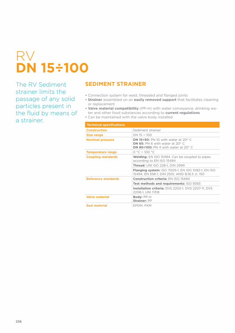
RV DN 15÷100
SEDIMENT STRAINER
• Connection system for weld, threaded and flanged joints• Strainer assembled on an easily removed support that facilitates cleaning
or replacement• Valve material compatibility (PP-H) with water conveyance, drinking wa-
ter and other food substances according to current regulations• Can be maintained with the valve body installed
The RV Sediment strainer limits the passage of any solid particles present in the fluid by means of a strainer.
Technical specifications
Construction Sediment strainer
Size range DN 15 ÷ 100
Nominal pressure DN 15÷50: PN 10 with water at 20° CDN 65: PN 6 with water at 20° CDN 80÷100: PN 4 with water at 20° C
Temperature range 0 °C ÷ 100 °C
Coupling standards Welding: EN ISO 15494. Can be coupled to pipes according to EN ISO 15494
Thread: UNI ISO 228-1, DIN 2999
Flanging system: ISO 7005-1, EN ISO 1092-1, EN ISO 15494, EN 558-1, DIN 2501, ANSI B.16.5 cl. 150
Reference standards Construction criteria: EN ISO 15494
Test methods and requirements: ISO 9393
Installation criteria: DVS 2202-1, DVS 2207-11, DVS 2208-1, UNI 11318
Valve material Body: PP-HStrainer: PP
Seal material EPDM, FKM
236
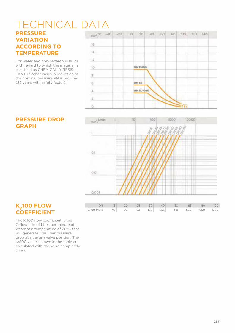
PRESSURE VARIATION ACCORDING TO TEMPERATURE
For water and non-hazardous fluids with regard to which the material is classified as CHEMICALLY RESIS-TANT. In other cases, a reduction of the nominal pressure PN is required (25 years with safety factor).
PRESSURE DROP GRAPH
KV100 FLOW
COEFFICIENT
The Kv100 flow coefficient is the
Q flow rate of litres per minute of water at a temperature of 20°C that will generate Δp= 1 bar pressure drop at a certain valve position. The Kv100 values shown in the table are calculated with the valve completely clean.
DN 15 20 25 32 40 50 65 80 100
Kv100 l/min 40 70 103 188 255 410 650 1050 1700
237
TECHNICAL DATA
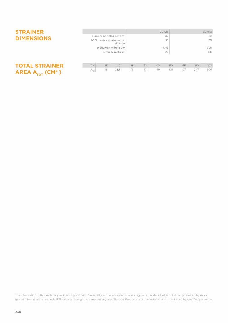
STRAINER DIMENSIONS
20÷25 32÷110
number of holes per cm2 37 32
ASTM series equivalent in strainer
18 20
ø equivalent hole μm 1016 889
strainer material PP PP
TOTAL STRAINER AREA A
TOT (CM2 )
DN 15 20 25 32 40 50 65 80 100
Atot
16 23,5 36 53 69 101 197 247 396
The information in this leaflet is provided in good faith. No liability will be accepted concerning technical data that is not directly covered by reco-
gnised international standards. FIP reserves the right to carry out any modification. Products must be installed and maintained by qualified personnel.
238
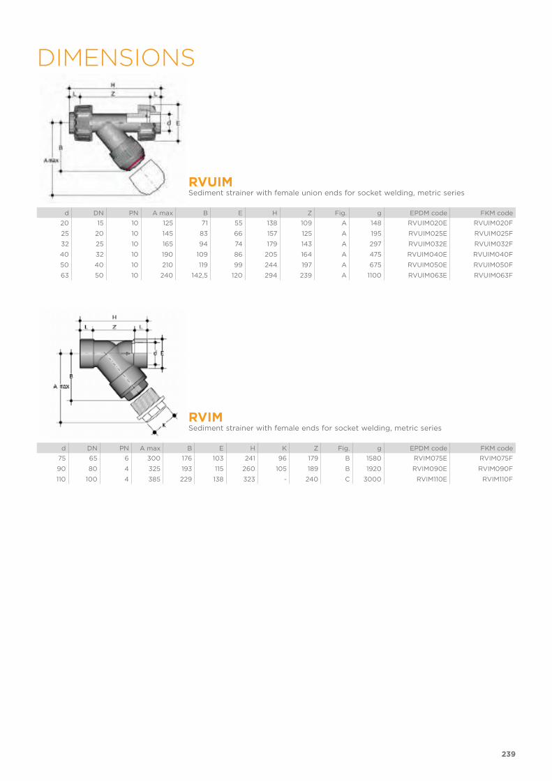
239
DIMENSIONS
RVUIMSediment strainer with female union ends for socket welding, metric series
d DN PN A max B E H Z Fig. g EPDM code FKM code
20 15 10 125 71 55 138 109 A 148 RVUIM020E RVUIM020F
25 20 10 145 83 66 157 125 A 195 RVUIM025E RVUIM025F
32 25 10 165 94 74 179 143 A 297 RVUIM032E RVUIM032F
40 32 10 190 109 86 205 164 A 475 RVUIM040E RVUIM040F
50 40 10 210 119 99 244 197 A 675 RVUIM050E RVUIM050F
63 50 10 240 142,5 120 294 239 A 1100 RVUIM063E RVUIM063F
RVIMSediment strainer with female ends for socket welding, metric series
d DN PN A max B E H K Z Fig. g EPDM code FKM code
75 65 6 300 176 103 241 96 179 B 1580 RVIM075E RVIM075F
90 80 4 325 193 115 260 105 189 B 1920 RVIM090E RVIM090F
110 100 4 385 229 138 323 - 240 C 3000 RVIM110E RVIM110F

240
RVUFMSediment strainer with BSP threaded female union ends
R DN PN A max B E H Z Fig. g EPDM code FKM code
1/2” 15 10 125 71 55 142 112 A 148 RVUFM012E RVUFM012F
3/4” 20 10 145 83 66 159 126 A 195 RVUFM034E RVUFM034F
1” 25 10 165 94 74 183 145 A 297 RVUFM100E RVUFM100F
1” 1/4 32 10 190 109 86 214 171 A 475 RVUFM114E RVUFM114F
1” 1/2 40 10 210 119 99 235 192 A 675 RVUFM112E RVUFM112F
2” 50 10 240 143 120 285 234 A 1100 RVUFM200E RVUFM200F
RVUOMSediment strainer with female union ends and fixed flanges, drilled EN/ISO/DIN PN10/16
d DN PN A max B F f H g EPDM code FKM code
20 15 10 125 72 65 14 163 248 RVUOM020E RVUOM020F
25 20 10 145 84 75 14 193 295 RVUOM025E RVUOM025F
32 25 10 165 95 85 14 211 397 RVUOM032E RVUOM032F
40 32 10 190 111 100 18 244 625 RVUOM040E RVUOM040F
50 40 10 210 120 110 18 277 825 RVUOM050E RVUOM050F
63 50 10 240 139 125 18 331 1250 RVUOM063E RVUOM063F
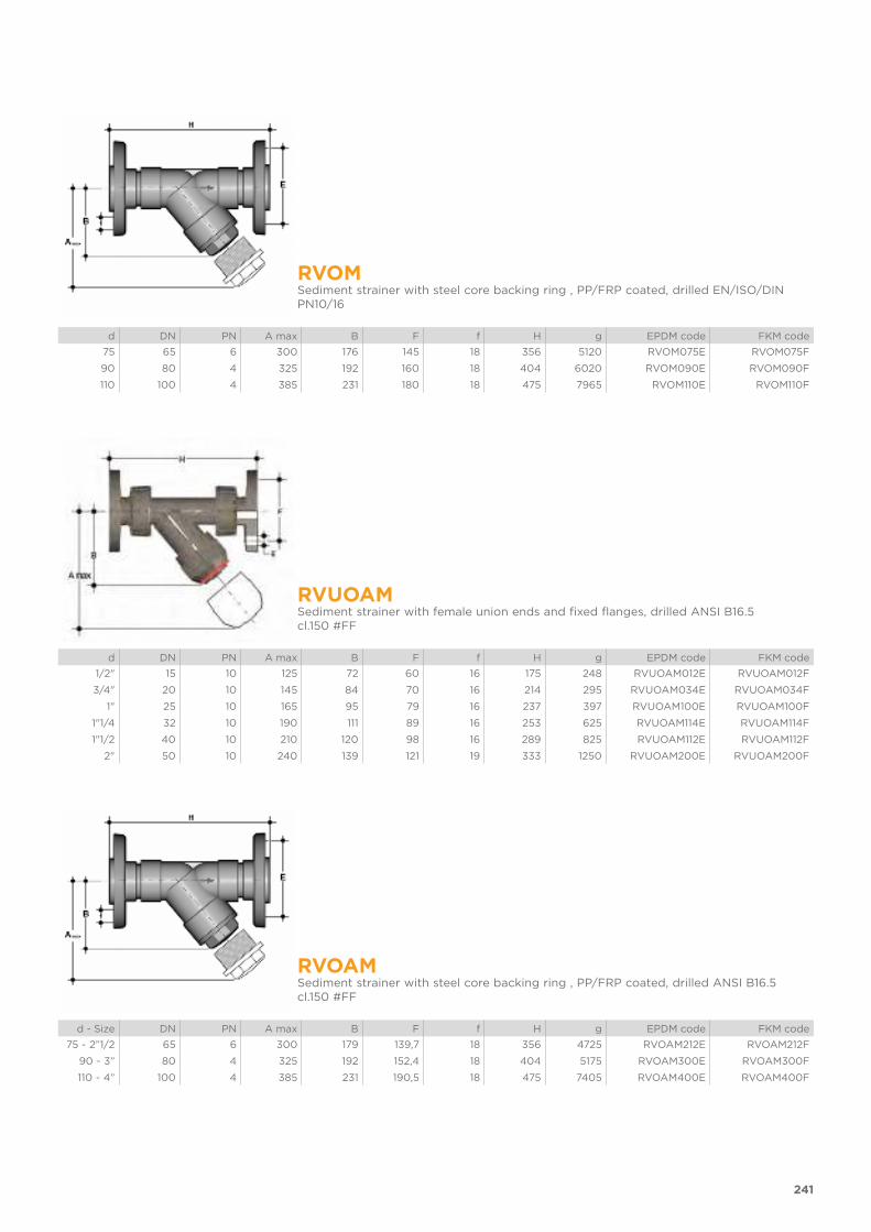
241
RVOMSediment strainer with steel core backing ring , PP/FRP coated, drilled EN/ISO/DIN PN10/16
d DN PN A max B F f H g EPDM code FKM code
75 65 6 300 176 145 18 356 5120 RVOM075E RVOM075F
90 80 4 325 192 160 18 404 6020 RVOM090E RVOM090F
110 100 4 385 231 180 18 475 7965 RVOM110E RVOM110F
RVUOAMSediment strainer with female union ends and fixed flanges, drilled ANSI B16.5 cl.150 #FF
d DN PN A max B F f H g EPDM code FKM code
1/2" 15 10 125 72 60 16 175 248 RVUOAM012E RVUOAM012F
3/4" 20 10 145 84 70 16 214 295 RVUOAM034E RVUOAM034F
1" 25 10 165 95 79 16 237 397 RVUOAM100E RVUOAM100F
1"1/4 32 10 190 111 89 16 253 625 RVUOAM114E RVUOAM114F
1"1/2 40 10 210 120 98 16 289 825 RVUOAM112E RVUOAM112F
2" 50 10 240 139 121 19 333 1250 RVUOAM200E RVUOAM200F
RVOAMSediment strainer with steel core backing ring , PP/FRP coated, drilled ANSI B16.5 cl.150 #FF
d - Size DN PN A max B F f H g EPDM code FKM code
75 - 2”1/2 65 6 300 179 139,7 18 356 4725 RVOAM212E RVOAM212F
90 - 3” 80 4 325 192 152,4 18 404 5175 RVOAM300E RVOAM300F
110 - 4” 100 4 385 231 190,5 18 475 7405 RVOAM400E RVOAM400F
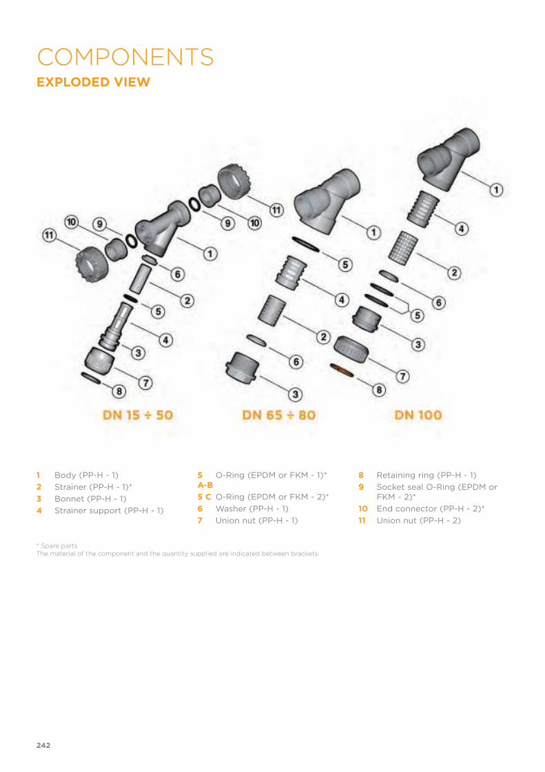
EXPLODED VIEW
1 Body (PP-H - 1)
2 Strainer (PP-H - 1)*
3 Bonnet (PP-H - 1)
4 Strainer support (PP-H - 1)
5 A-B
O-Ring (EPDM or FKM - 1)*
5 C O-Ring (EPDM or FKM - 2)*
6 Washer (PP-H - 1)
7 Union nut (PP-H - 1)
8 Retaining ring (PP-H - 1)
9 Socket seal O-Ring (EPDM or FKM - 2)*
10 End connector (PP-H - 2)*
11 Union nut (PP-H - 2)
* Spare partsThe material of the component and the quantity supplied are indicated between brackets
242
COMPONENTS

DISASSEMBLYDN 15÷50 (FIG. A) - DN 100 (FIG. C)
1) Isolate the sediment strainer from the fluid flow and empty the system up-stream.
2) Unscrew the union nut (7) and sep-arate the bonnet-support (3-4) from the body (1).
3) Remove the bottom washer (6) from the bonnet-support (3-4).
4) Remove the retaining ring (8) and separate the union nut (7) from the bonnet (3).
5) Remove the O-Ring from the bonnet (5).
DN 65÷80 (FIG. B)
1) Isolate the sediment strainer from the fluid flow and empty the system up-stream.
2) Unscrew the bonnet (3) and separate it from the body (1).
3) Remove the support (4) from the bonnet (3).
4) Remove the washer (6) from the bon-net (3) and the O-Ring (5) from its seating in the body.
ASSEMBLYDN 15÷50 (FIG. A) - DN 100 (FIG. C)
1) Insert the O-Ring (5) in its seating in the bonnet (3).
2) Insert the bonnet (3) in union nut (7) and fix the two components using the retaining ring (8).
3) Insert the strainer (2) in the bonnet support (3-4) and hold in place with the washer (6).
4) Insert the bonnet (3) in the body (1) and tighten the union nut (7).
DN 65÷80 (FIG. B)
1) Insert the O-Ring (5) in the body (1)2) Insert the washer (6) in the bonnet (3)3) Insert the strainer (2) in its support (4)4) Insert the support (4) in the bonnet
(3)5) Screw the bonnet (3) in the body (1)
Note: maintenance operations can be carried out with the valve body installed. During assembly, it is advisable to lubri-cate the rubber seals. Mineral oils are not recommended for this task as they react aggressively with EPDM rubber.
Fig. A
Fig. B
Fig. C
243
DN 15÷50 (fig. A)
The sediment strainer can be installed in any position, making sure that the arrow stamped on the body indicates the direction of fluid flow and that the strainer part is facing downwards. To avoid damaging the strainer, appro-priate devices must beinstalled on the line to prevent backflow.1) Unscrew the union nuts (11) and slide them onto the pipe.2) Heat weld the end connectors (10) onto the pipe segments.3) Position the sediment strainer between the end connectors4) Tighten the union nuts.
DN 65÷80 (fig. B) e DN 100 (fig. C)
The joint must be made by solvent welding the pipe directly into the socket of the valve body.
WARNINGS - Always check the cleanliness of the filter elements.
244
INSTALLATION


VR DN 15÷80
PP-H
Check valve

VR DN 15÷80
CHECK VALVE
• Connection system for weld, threaded and flanged joints• No metal parts in contact with the fluid• Piston with counterweight able to work with high intensity fluid• Limited pressure drop. Only minimum back pressure is required for the
hermetic seal• Valve material compatibility (PP-H) with water conveyance, drinking wa-
ter and other food substances according to current regulations• Can be maintained with the valve body installed
The VR is an angle seat check valve with weighted PP-H piston that allows the passage of fluid in one direction only.
Technical specifications
Construction Angle seat check valve
Size range DN 15 ÷ 80
Nominal pressure DN 10÷50: PN 10 with water at 20° CDN 65 PN 6 with water at 20° CDN 80: PN 4 with water at 20° C
Temperature range 0 °C ÷ 100 °C
Coupling standards Welding: EN ISO 15494. Can be coupled to pipes according to EN ISO 15494
Thread: ISO 228-1, DIN 2999
Flanging system: ISO 7005-1, EN 1092-1, EN ISO 15494, EN 558-1, DIN 2501, ANSI B.16.5 cl. 150
Reference standards Construction criteria: EN ISO 16137, EN ISO 15494
Test methods and requirements: ISO 9393
Installation criteria: DVS 2202-1, DVS 2207-11, DVS 2208-1, UNI 11318
Valve material PP-H
Seal material EPDM or FKM
248

PRESSURE VARIATION ACCORDING TO TEMPERATURE
For water and non-hazardous fluids with regard to which the material is classified as CHEMICALLY RESIS-TANT. In other cases, a reduction of the nominal pressure PN is required (25 years with safety factor).
PRESSURE DROP GRAPH
KV100 FLOW
COEFFICIENT
The Kv100 flow coefficient is the
Q flow rate of litres per minute of water at a temperature of 20°C that will generate Δp= 1 bar pressure drop at a certain valve position. The Kv100 values shown in the table are calculated with the valve completely open.
DN 15 20 25 32 40 50 65 80
Kv100 l/min 110 205 375 560 835 1300 1950 2600
MINIMUM PRESSURE REQUIRED TO LIFT THE PISTON
DN 15 20 25 32 40 50 65 80
bar 0,008 0,009 0,014 0,017 0,018 0,021 0,022 0,022
249
TECHNICAL DATA
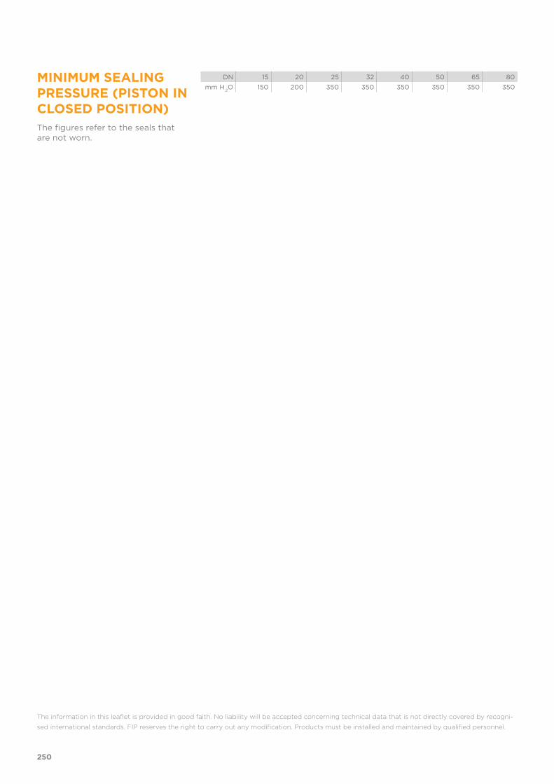
MINIMUM SEALING PRESSURE (PISTON IN CLOSED POSITION)
The figures refer to the seals that are not worn.
DN 15 20 25 32 40 50 65 80
mm H.2O 150 200 350 350 350 350 350 350
The information in this leaflet is provided in good faith. No liability will be accepted concerning technical data that is not directly covered by recogni-
sed international standards. FIP reserves the right to carry out any modification. Products must be installed and maintained by qualified personnel.
250
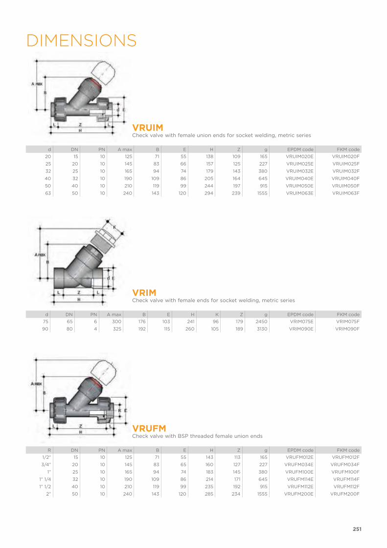
251
DIMENSIONS
VRUIMCheck valve with female union ends for socket welding, metric series
d DN PN A max B E H Z g EPDM code FKM code
20 15 10 125 71 55 138 109 165 VRUIM020E VRUIM020F
25 20 10 145 83 66 157 125 227 VRUIM025E VRUIM025F
32 25 10 165 94 74 179 143 380 VRUIM032E VRUIM032F
40 32 10 190 109 86 205 164 645 VRUIM040E VRUIM040F
50 40 10 210 119 99 244 197 915 VRUIM050E VRUIM050F
63 50 10 240 143 120 294 239 1555 VRUIM063E VRUIM063F
VRIMCheck valve with female ends for socket welding, metric series
d DN PN A max B E H K Z g EPDM code FKM code
75 65 6 300 176 103 241 96 179 2450 VRIM075E VRIM075F
90 80 4 325 192 115 260 105 189 3130 VRIM090E VRIM090F
VRUFMCheck valve with BSP threaded female union ends
R DN PN A max B E H Z g EPDM code FKM code
1/2” 15 10 125 71 55 143 113 165 VRUFM012E VRUFM012F
3/4” 20 10 145 83 65 160 127 227 VRUFM034E VRUFM034F
1” 25 10 165 94 74 183 145 380 VRUFM100E VRUFM100F
1” 1/4 32 10 190 109 86 214 171 645 VRUFM114E VRUFM114F
1” 1/2 40 10 210 119 99 235 192 915 VRUFM112E VRUFM112F
2” 50 10 240 143 120 285 234 1555 VRUFM200E VRUFM200F

252
VRUOMCheck valve with union ends and fixed flanges, drilled EN/ISO/DIN PN10/16
d DN PN A max B F f H g EPDM code FKM code
20 15 10 125 72 65 14 163 265 VRUOM020E VRUOM020F
25 20 10 145 84 75 14 193 327 VRUOM025E VRUOM025F
32 25 10 165 95 85 14 211 480 VRUOM032E VRUOM032F
40 32 10 190 111 100 18 244 795 VRUOM040E VRUOM040F
50 40 10 210 120 110 18 277 1065 VRUOM050E VRUOM050F
63 50 10 240 139 125 18 331 1705 VRUOM063E VRUOM063F
VROMCheck valve with steel core backing ring, PP/FRP coated, drilled EN/ISO/DIN PN10/16
d DN PN A max B F f H g EPDM code FKM code
75 65 6 300 179 145 18 356 5990 VROM075E VROM075F
90 80 4 325 192 160 18 404 7230 VROM090E VROM090F
VRUOAMCheck valve with union ends and fixed flanges, drilled ANSI B16.5 cl.150 #FF
Size DN PN A max B F f H g EPDM code FKM code
1/2" 15 10 125 72 60 16 175 265 VRUOAM012E VRUOAM012F
3/4" 20 10 145 84 70 16 214 327 VRUOAM034E VRUOAM034F
1" 25 10 165 95 79 16 237 480 VRUOAM100E VRUOAM100F
1"1/4 32 10 190 111 89 16 253 795 VRUOAM114E VRUOAM114F
1"1/2 40 10 210 120 98 16 289 1065 VRUOAM112E VRUOAM112F
2" 50 10 240 139 121 19 333 1705 VRUOAM200E VRUOAM200F
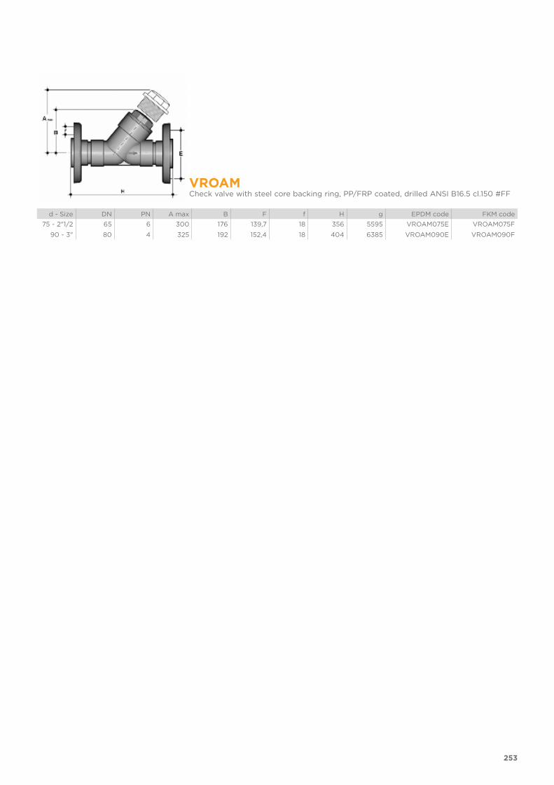
253
VROAMCheck valve with steel core backing ring, PP/FRP coated, drilled ANSI B16.5 cl.150 #FF
d - Size DN PN A max B F f H g EPDM code FKM code
75 - 2"1/2 65 6 300 176 139,7 18 356 5595 VROAM075E VROAM075F
90 - 3" 80 4 325 192 152,4 18 404 6385 VROAM090E VROAM090F

EXPLODED VIEW
1 Body (PP-H - 1)
2 Piston (PP-H - 1)
3 Bonnet (PP-H - 1)
4 O-Ring (EPDM or FKM - 1/2)*
5 Piston flat gasket (EPDM o FKM - 1)*
6 Union nut (PP-H - 1)
7 Retaining ring (PP-H - 1)
8 Socket seal O-Ring (EPDM or FKM - 2)*
9 End connector (PP-H - 2)*
10 Union nut (PP-H - 2)
* Spare partsThe material of the component and the quantity supplied are indicated between brackets
254
COMPONENTS
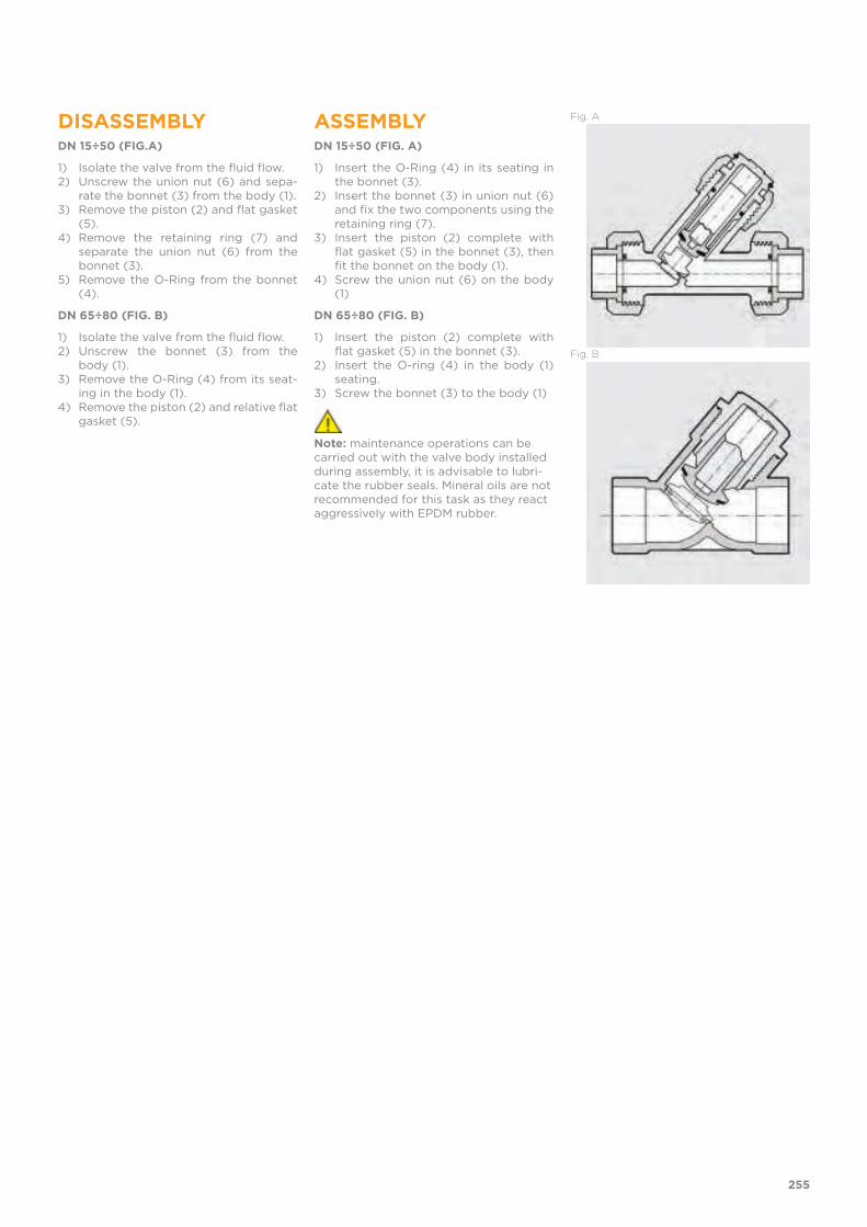
DISASSEMBLYDN 15÷50 (FIG.A)
1) Isolate the valve from the fluid flow.2) Unscrew the union nut (6) and sepa-
rate the bonnet (3) from the body (1).3) Remove the piston (2) and flat gasket
(5).4) Remove the retaining ring (7) and
separate the union nut (6) from the bonnet (3).
5) Remove the O-Ring from the bonnet (4).
DN 65÷80 (FIG. B)
1) Isolate the valve from the fluid flow.2) Unscrew the bonnet (3) from the
body (1).3) Remove the O-Ring (4) from its seat-
ing in the body (1).4) Remove the piston (2) and relative flat
gasket (5).
ASSEMBLYDN 15÷50 (FIG. A)
1) Insert the O-Ring (4) in its seating in the bonnet (3).
2) Insert the bonnet (3) in union nut (6) and fix the two components using the retaining ring (7).
3) Insert the piston (2) complete with flat gasket (5) in the bonnet (3), then fit the bonnet on the body (1).
4) Screw the union nut (6) on the body (1)
DN 65÷80 (FIG. B)
1) Insert the piston (2) complete with flat gasket (5) in the bonnet (3).
2) Insert the O-ring (4) in the body (1) seating.
3) Screw the bonnet (3) to the body (1)
Note: maintenance operations can be carried out with the valve body installed during assembly, it is advisable to lubri-cate the rubber seals. Mineral oils are not recommended for this task as they react aggressively with EPDM rubber.
Fig. A
Fig. B
255

The check valve can be installed on vertical or horizontal axis pipes. The bonnet (3) must however always be turned upwards as the piston works by gravity.If the valve is installed in a vertical position, if the connection is solvent wel-ded, make sure that the solvent cement does not enter inside the body, as this would damage the seating of the seal.Install the valve such that the arrow stamped on the body indicates the direction of fluid flow .
WARNINGS Do not used compressed air or other gases to test thermoplastic lines.
256
INSTALLATION

257

258

C O-Ring code
d nominal external diameter in mm
DN nominal internal diameter in mm
EPDM ethylene propylene elastomer
FKM (FPM) fluoroelastomer
g weight in grams
HIPVC PVC high impact
K bonnet key
Kg weight in kilograms
L length in metres
M bolts
MRS minimum guaranteed breaking
strength of the material at 20° C - water - for 50 years of service
n number of flange holes
NBR acrylonitrile butadiene elastomer
PA-GR fibreglass reinforced polyamide
PBT polybutylene terephthalate
PE polyethylene
PN nominal pressure in bar (max.
operating pressure at 20 °C water)
POM polyoxymethylene
PP-GR fibreglass reinforced polypropylene
PP-H polypropylene homopolymer
PVC-C chlorinated polyvinyl chloride
PVC-U unplasticized polyvinylchloride
PVDF polyvinylidene difluoride
PTFE polyethrafluorethylene
R nominal thread size in inches
S thickness series = SDR-1 2
s pipe thickness in mm
SDR standard dimension ratio = d / s
Sp flange thickness on flanged valves
U number of flange holes for flanged valves
KEYABBREVIATIONS
259


Co
de
LE
VA
RA
P 0
9/2
019
FIP - Formatura Iniezione Polimeri
Loc. Pian di Parata, 16015 Casella Genova Italy
Tel. +39 010 9621.1
Fax +39 010 9621.209
www.fipnet.com
Related Documents