www.bhrgroup.co.uk 14th International Conference Multiphase Production Technology Cannes, France - 17th - 19th June 2009 SDAG Discretization Methods for Multiphase Flow Simulation of Ultra-Long Gas-Condensate Pipelines Erich Zakarian & Henning Holm Shtokman Development A.G.

Pipeline discretization (BHR Multiphase 2009)
Jul 14, 2015
Welcome message from author
This document is posted to help you gain knowledge. Please leave a comment to let me know what you think about it! Share it to your friends and learn new things together.
Transcript

www.bhrgroup.co.uk
14th International Conference Multiphase Production Technology
Cannes, France - 17th - 19th June 2009
SDAG
Discretization Methods for Multiphase
Flow Simulation of Ultra-Long
Gas-Condensate Pipelines
Erich Zakarian & Henning HolmShtokman Development A.G.
14th International Conference Multiphase Production Technology
Cannes, France - 17th - 19th June 2009
SDAG
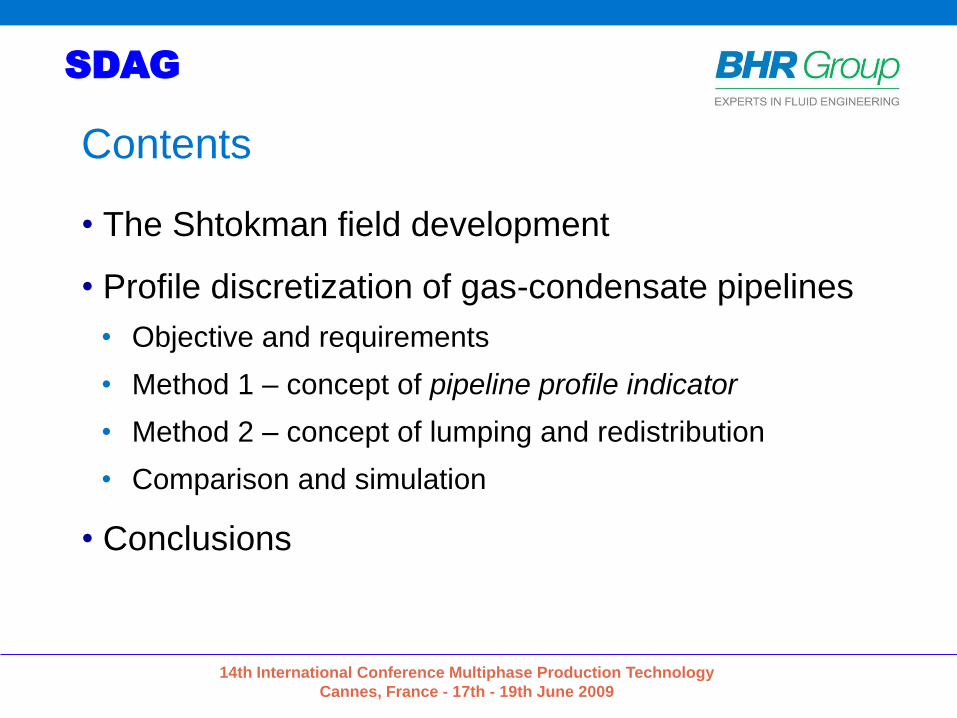
Contents
• The Shtokman field development
• Profile discretization of gas-condensate pipelines
• Objective and requirements
• Method 1 – concept of pipeline profile indicator
• Method 2 – concept of lumping and redistribution
• Comparison and simulation
• Conclusions

14th International Conference Multiphase Production Technology
Cannes, France - 17th - 19th June 2009
SDAG
Integrated Development of the Shtokman
Gas-Condensate Field – Phase 1

14th International Conference Multiphase Production Technology
Cannes, France - 17th - 19th June 2009
SDAG
Cannes
ParisMurmansk
Teriberka
Shtokman
Gas export to shore • 70 MSm3/d (2.5 BCFD) – Phase 1
• 2 x 36” ND trunklines (0.86 m ID)
• Length 558 km (347 miles)
• Dry two-phase flow
• CGR = from 2 to 16 Sm3/MSm3
14th International Conference Multiphase Production Technology
Cannes, France - 17th - 19th June 2009
SDAG
-400
-300
-200
-100
0
100
200
0 100 200 300 400 500
Distance [km]
Ele
vati
on
[m
]
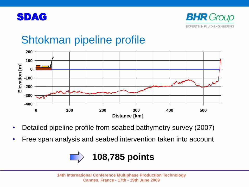
Shtokman pipeline profile
• Detailed pipeline profile from seabed bathymetry survey (2007)
• Free span analysis and seabed intervention taken into account
108,785 points
14th International Conference Multiphase Production Technology
Cannes, France - 17th - 19th June 2009
SDAG
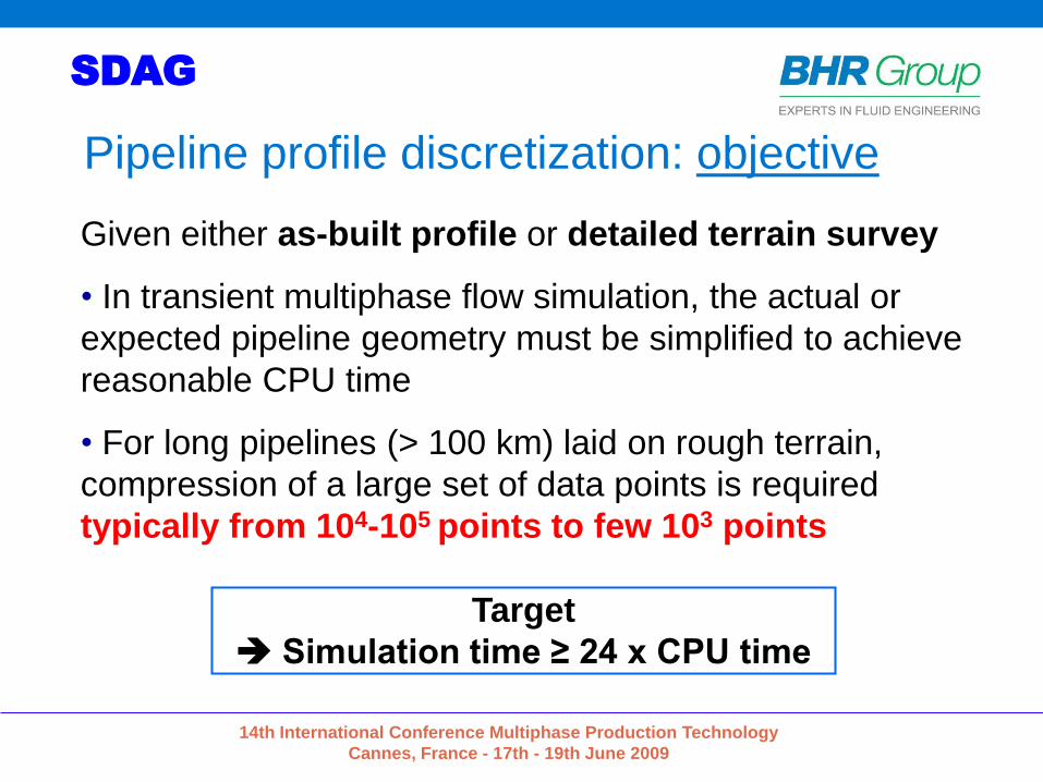
Given either as-built profile or detailed terrain survey
• In transient multiphase flow simulation, the actual or
expected pipeline geometry must be simplified to achieve
reasonable CPU time
• For long pipelines (> 100 km) laid on rough terrain,
compression of a large set of data points is required
typically from 104-105 points to few 103 points
Pipeline profile discretization: objective
Target
Simulation time ≥ 24 x CPU time

14th International Conference Multiphase Production Technology
Cannes, France - 17th - 19th June 2009
SDAG
The Shtokman case
• Average pipe length will be approximately 200 m
• Avoid small pipe sections to maximize numerical time steps
Δt < min (Δx/U)i
Target ≈ 2500 pipesfor a total length of 554 km

14th International Conference Multiphase Production Technology
Cannes, France - 17th - 19th June 2009
SDAG
Pipeline profile discretization: requirements1. The total pipe length must be conserved
2. The simplified geometry must have the same overall shape (large and small scale undulations)
3. The pipe angle distribution of the discretized profile must be as close as possible to the original distribution
4. The total climb (cumulative length of uphill pipes) must be conserved to predict the same overall liquid content in steady-state flow conditions
1
2
4
3
Original profile
14th International Conference Multiphase Production Technology
Cannes, France - 17th - 19th June 2009
SDAG
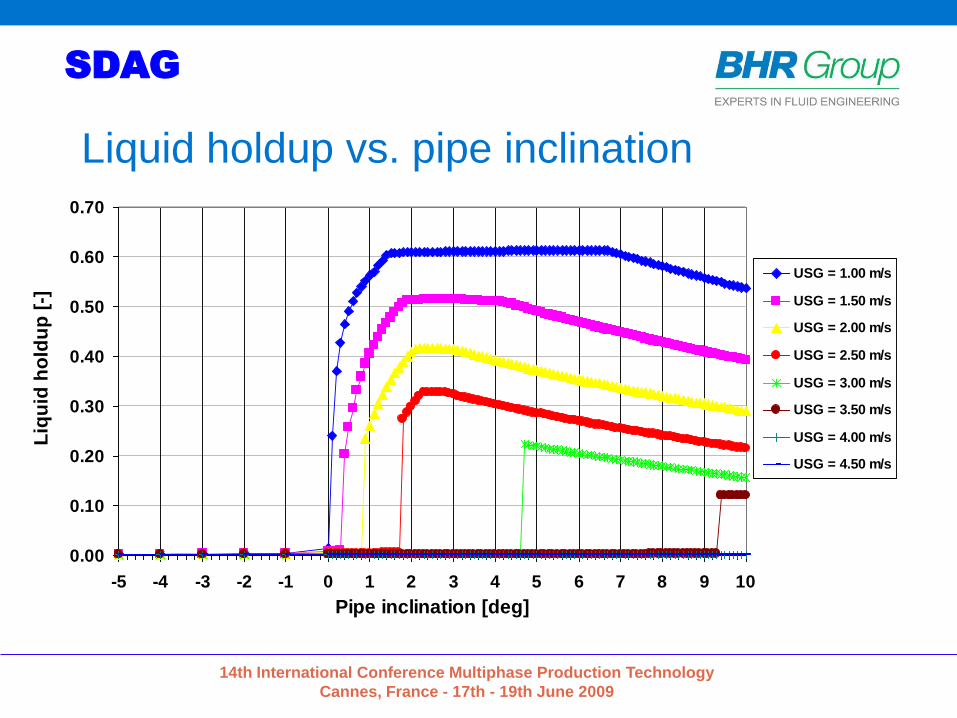
Liquid holdup vs. pipe inclinationOLGAS 5.3: liquid holdup vs. pipe inclination and gas superficial velocity
USL=0.003 m/s - G=180 kg/m3 - o=775 kg/m3 - mG=0.02 cP - mO=2.5 cP
=0.0025 N/m - Wall roughness=30 mm - Inner diameter=0.9906 m
0.00
0.10
0.20
0.30
0.40
0.50
0.60
0.70
-5 -4 -3 -2 -1 0 1 2 3 4 5 6 7 8 9 10
Pipe inclination [deg]
Liq
uid
ho
ldu
p [
-]
USG = 1.00 m/s
USG = 1.50 m/s
USG = 2.00 m/s
USG = 2.50 m/s
USG = 3.00 m/s
USG = 3.50 m/s
USG = 4.00 m/s
USG = 4.50 m/s

14th International Conference Multiphase Production Technology
Cannes, France - 17th - 19th June 2009
SDAG
Two methods for a single objective
Method 1: concept of pipeline profile indicator
• Select, simplify and complexify relevant sub-profiles
• Use the pipeline profile indicator and the total climb to
match the original angle distribution
Method 2: concept of lumping elements with similar
inclination
• Redistribution to match the original large & small
scale topographies

14th International Conference Multiphase Production Technology
Cannes, France - 17th - 19th June 2009
SDAG
Method 1
Concept of pipeline profile indicator
14th International Conference Multiphase Production Technology
Cannes, France - 17th - 19th June 2009
SDAG
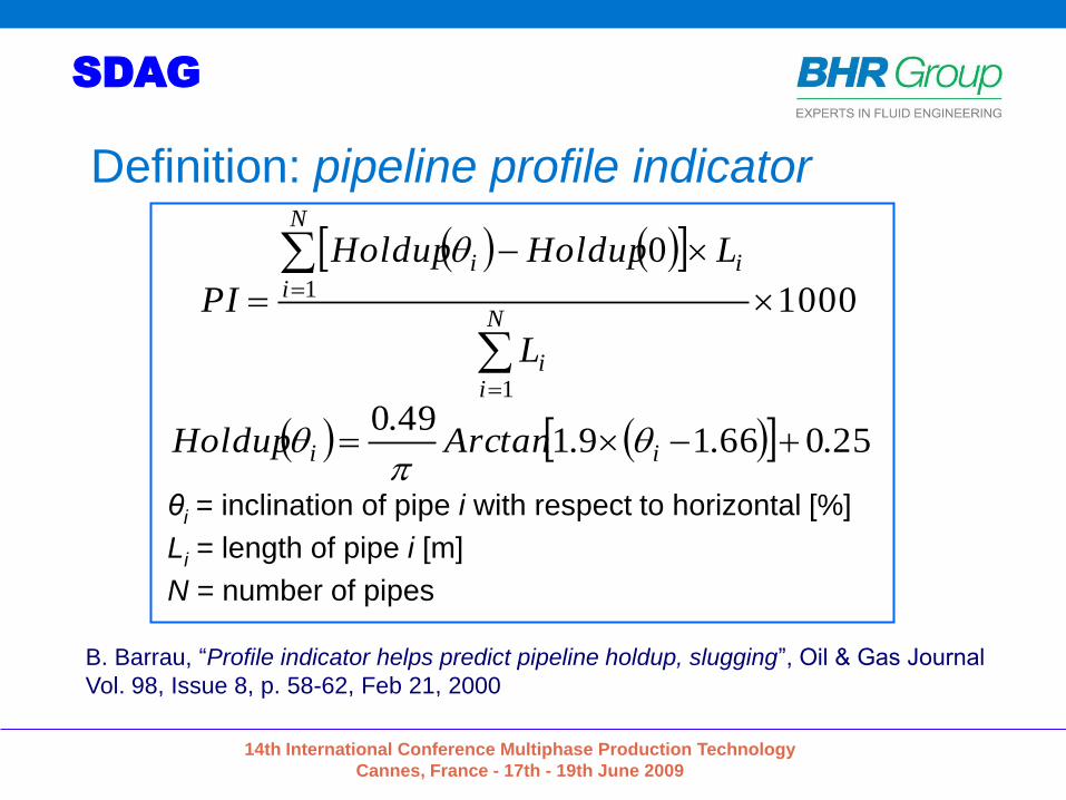
Definition: pipeline profile indicator
θi = inclination of pipe i with respect to horizontal [%]
Li = length of pipe i [m]
N = number of pipes
B. Barrau, “Profile indicator helps predict pipeline holdup, slugging”, Oil & Gas Journal
Vol. 98, Issue 8, p. 58-62, Feb 21, 2000
1000
0
1
1
N
ii
N
iii
L
LHoldupHoldup
PI
25066191490
...tanArc.
Holdup ii
14th International Conference Multiphase Production Technology
Cannes, France - 17th - 19th June 2009
SDAG
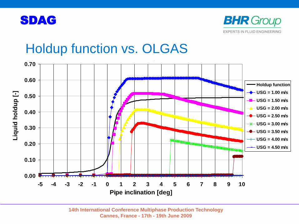
Holdup function vs. OLGAS OLGAS 5.3: liquid holdup vs. pipe inclination and gas superficial velocity
USL=0.003 m/s - G=180 kg/m3 - o=775 kg/m3 - mG=0.02 cP - mO=2.5 cP
=0.0025 N/m - Wall roughness=30 mm - Inner diameter=0.9906 m
0.00
0.10
0.20
0.30
0.40
0.50
0.60
0.70
-5 -4 -3 -2 -1 0 1 2 3 4 5 6 7 8 9 10
Pipe inclination [deg]
Liq
uid
ho
ldu
p [
-]
Holdup function
USG = 1.00 m/s
USG = 1.50 m/s
USG = 2.00 m/s
USG = 2.50 m/s
USG = 3.00 m/s
USG = 3.50 m/s
USG = 4.00 m/s
USG = 4.50 m/s
14th International Conference Multiphase Production Technology
Cannes, France - 17th - 19th June 2009
SDAG
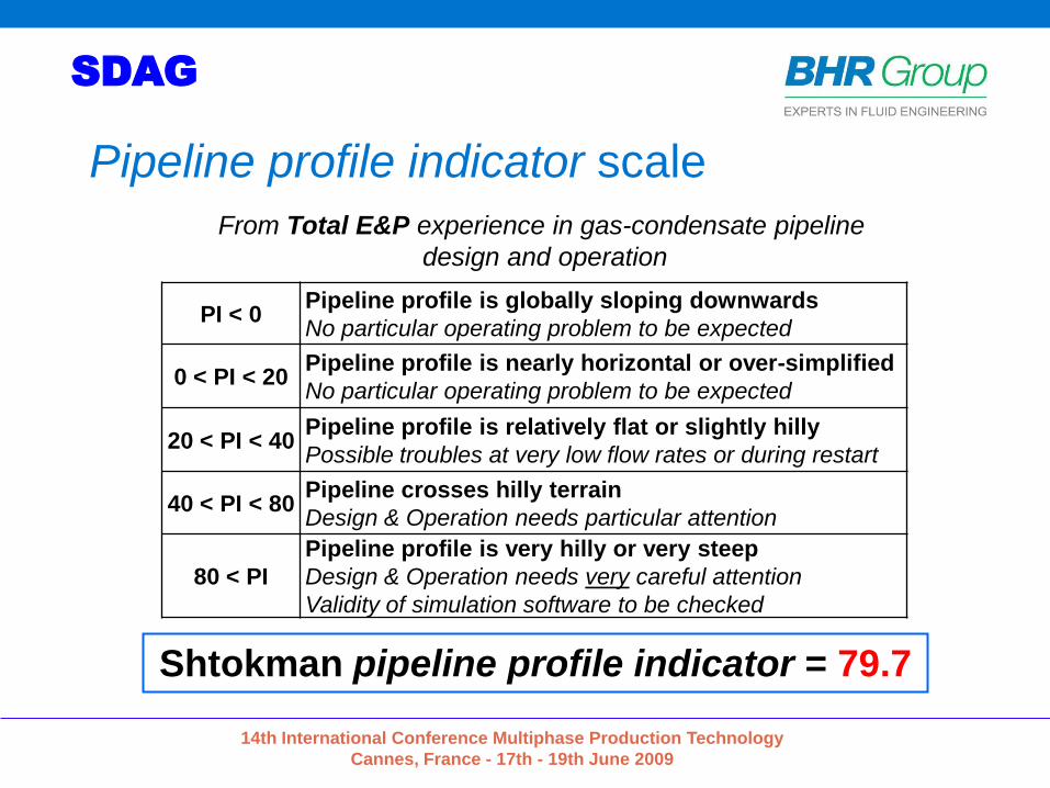
Pipeline profile indicator scale
PI < 0Pipeline profile is globally sloping downwards
No particular operating problem to be expected
0 < PI < 20Pipeline profile is nearly horizontal or over-simplified
No particular operating problem to be expected
20 < PI < 40Pipeline profile is relatively flat or slightly hilly
Possible troubles at very low flow rates or during restart
40 < PI < 80Pipeline crosses hilly terrain
Design & Operation needs particular attention
80 < PI
Pipeline profile is very hilly or very steep
Design & Operation needs very careful attention
Validity of simulation software to be checked
From Total E&P experience in gas-condensate pipeline
design and operation
Shtokman pipeline profile indicator = 79.7
14th International Conference Multiphase Production Technology
Cannes, France - 17th - 19th June 2009
SDAG
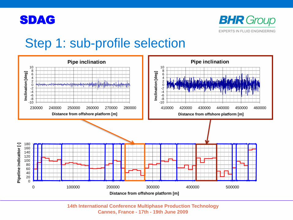
Step 1: sub-profile selection
020406080
100120140160180
0 100000 200000 300000 400000 500000
Pip
eli
ne in
dic
att
or
[-]
Distance from offshore platform [m]
-10-8-6-4-202468
10
230000 240000 250000 260000 270000 280000
Incli
nati
on
[d
eg
]
Distance from offshore platform [m]
Pipe inclination
-10-8-6-4-202468
10
410000 420000 430000 440000 450000 460000
Incli
nati
on
[d
eg
]
Distance from offshore platform [m]
Pipe inclination
14th International Conference Multiphase Production Technology
Cannes, France - 17th - 19th June 2009
SDAG
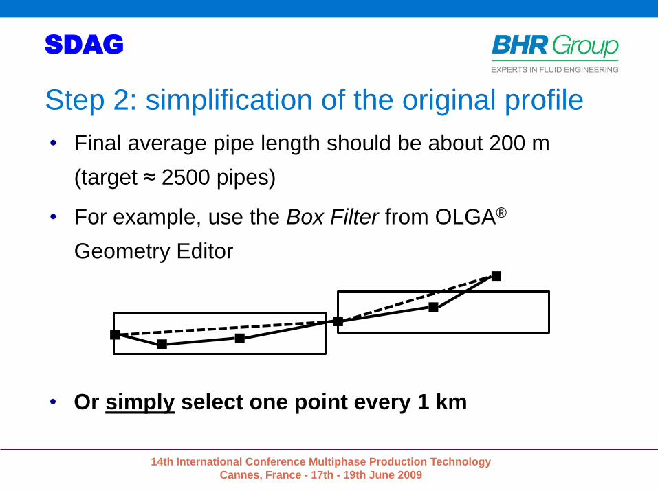
• Final average pipe length should be about 200 m
(target ≈ 2500 pipes)
• For example, use the Box Filter from OLGA®
Geometry Editor
• Or simply select one point every 1 km
Step 2: simplification of the original profile
14th International Conference Multiphase Production Technology
Cannes, France - 17th - 19th June 2009
SDAG
0500100015002000250030003500400045005000
-400
-300
-200
-100
0
100
200
0 100000 200000 300000 400000 500000
To
tal c
limb
[m]E
levati
on
[m
]
Distance from offshore platform [m]
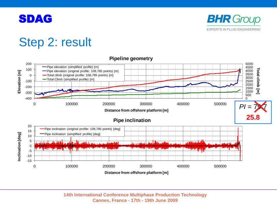
Pipeline geometry
Pipe elevation (simplified profile) [m]
Pipe elevation (original profile: 108,785 points) [m]
Total climb (original profile: 108,785 points) [m]
Total Climb (simplified profile) [m]
-15
-10
-5
0
5
10
15
20
0 100000 200000 300000 400000 500000
Incli
nati
on
[d
eg
]
Distance from offshore platform [m]
Pipe inclination
Pipe inclination (original profile: 108,785 points) [deg]
Pipe inclination (simplified profile) [deg]
PI = 79.7
25.8
Step 2: result
14th International Conference Multiphase Production Technology
Cannes, France - 17th - 19th June 2009
SDAG
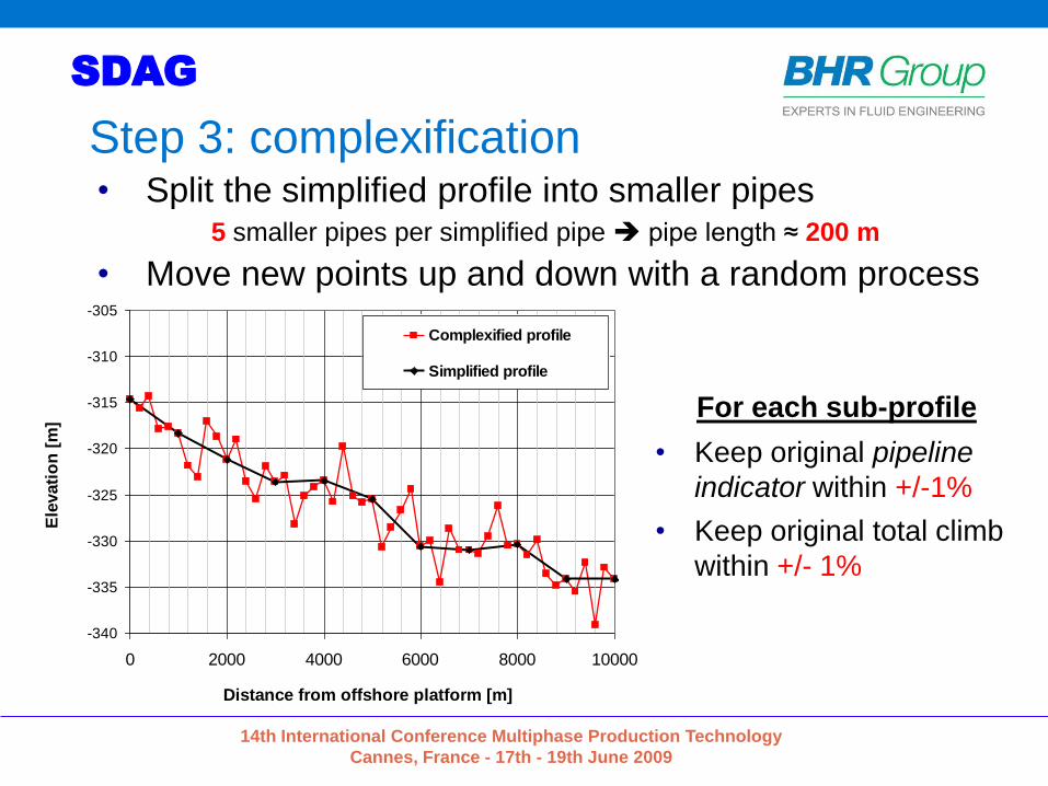
Step 3: complexification
Pipeline geometry
-340
-335
-330
-325
-320
-315
-310
-305
0 2000 4000 6000 8000 10000
Distance from offshore platform [m]
Ele
vati
on
[m
]
Complexified profile
Simplified profile
Inverse of the standard normal cumulative distribution
-4
-3
-2
-1
0
1
2
3
4
0 0.1 0.2 0.3 0.4 0.5 0.6 0.7 0.8 0.9 1
ProbabilityN
orm
Std
-1
For each sub-profile
• Keep original pipeline
indicator within +/-1%
• Keep original total climb
within +/- 1%
• Split the simplified profile into smaller pipes5 smaller pipes per simplified pipe pipe length ≈ 200 m
• Move new points up and down with a random process

14th International Conference Multiphase Production Technology
Cannes, France - 17th - 19th June 2009
SDAG
0500100015002000250030003500400045005000
-400
-300
-200
-100
0
100
200
0 100000 200000 300000 400000 500000
To
tal c
limb
[m]E
levati
on
[m
]
Distance from offshore platform [m]
Pipeline geometry
Pipe elevation (complexified profile) [m]
Pipe elevation (original profile: 108,785 points) [m]
Total climb (complexified profile) [m]
Total climb (original profile: 108,785 points) [m]
-15
-10
-5
0
5
10
15
20
0 100000 200000 300000 400000 500000
Incli
nati
on
[d
eg
]
Distance from offshore platform [m]
Pipe inclination
Pipe inclination (original profile: 108,785 points) [deg]
Pipe inclination (complexified profile) [deg]
Step 3: result
14th International Conference Multiphase Production Technology
Cannes, France - 17th - 19th June 2009
SDAG
Method 2
Concept of lumping elements with similar inclination

14th International Conference Multiphase Production Technology
Cannes, France - 17th - 19th June 2009
SDAG
Method 2 – “Lumping and redistributing”
1. Define the criteria (in priority) to determine the pipe length to be used for
the simplified profile :
1. minimum pipe length
2. maximum elevation change for a pipe element
3. maximum pipe length
2. Sort all elements in the detailed profile by inclination in ascending order
3. Lump together the sorted elements to longer pipes, starting with the
element with the steepest downhill inclination. The length of each pipe
element is then limited by dominating criteria in 1).
4. Distribute the pipe elements in the simplified profile to match the large
scale and small scale topography of the detailed profile.
14th International Conference Multiphase Production Technology
Cannes, France - 17th - 19th June 2009
SDAG
Pipelength (m)
Pip
e e
lev
ati
on
ch
an
ge
(m
)
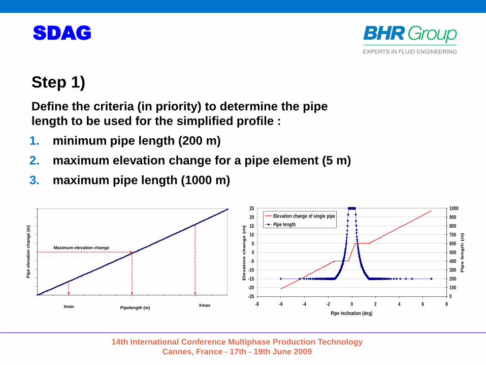
Xmin Xmax
Maximum elevation change
-25
-20
-15
-10
-5
0
5
10
15
20
25
-8 -6 -4 -2 0 2 4 6 8
Pipe inclination (deg)
Ele
va
tio
n c
ha
ng
e (
m)
0
100
200
300
400
500
600
700
800
900
1000
Pip
e l
en
gth
(m
)
Elevation change of single pipe
Pipe length
Step 1)
Define the criteria (in priority) to determine the pipe
length to be used for the simplified profile :
1. minimum pipe length (200 m)
2. maximum elevation change for a pipe element (5 m)
3. maximum pipe length (1000 m)
14th International Conference Multiphase Production Technology
Cannes, France - 17th - 19th June 2009
SDAG
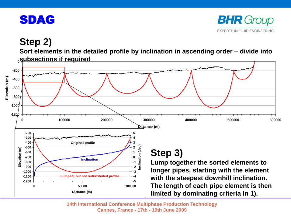
Step 3)Lump together the sorted elements to
longer pipes, starting with the element
with the steepest downhill inclination.
The length of each pipe element is then
limited by dominating criteria in 1).
-1200
-1000
-800
-600
-400
-200
0
0 100000 200000 300000 400000 500000 600000
Distance (m)
Ele
vati
on
(m
)
-1200
-1100
-1000
-900
-800
-700
-600
-500
-400
-300
-200
0 50000 100000
Distance (m)
Ele
vati
on
(m
)
-5
-4
-3
-2
-1
0
1
2
3
4
5
Incli
nati
on
(d
eg
)Original profile
Inclination
Lumped, but not redistributed profile
Step 2) Sort elements in the detailed profile by inclination in ascending order – divide into
subsections if required

14th International Conference Multiphase Production Technology
Cannes, France - 17th - 19th June 2009
SDAG
”Inclination classes” versus ”lumping by inclination in ascending order ”
0
100000
200000
300000
400000
500000
600000
-5 -4 -3 -2 -1 0 1 2 3 4 5
Inclination (deg)
Accu
mu
late
d l
en
gth
(m
)
grouping by inclination classes
Lumping by inclinations in
ascending order
0
200
400
600
800
1000
1200
1400
1600
1800
2000
30 35 40 45 50 55 60 65 70
Export flow rate [MSm3/d]
Co
nd
en
sa
te c
on
ten
t [m
3]
Original profile 20-70 km
'lumping by inclination in ascending order'
'Sorted by inclination classes'

14th International Conference Multiphase Production Technology
Cannes, France - 17th - 19th June 2009
SDAG
Step 4)Redistribution of elements by “Simulated Annealing” (Travelling salesman problem)
“minimize distance between detailed profile and simplified profile”
yi : values from the simplified profile
ŷi : values from the detailed profile
wi : weight factor
where as “i” denotes:
1) Elevation
2) “Total Climb”
3) “Pipeline Indicator” *
2)()( ii ii yywyF
Cost function:
-1200
-1000
-800
-600
-400
-200
0
0 100000 200000 300000 400000 500000 600000
Distance (m)
Ele
vati
on
(m
)
-400
-350
-300
-250
-200
-150
-100
-50
0
0 100000 200000 300000 400000 500000 600000
Distance (m)
Ele
vati
on
(m
)
-300
-290
-280
-270
-260
-250
-240
-230
70000 75000 80000 85000 90000 95000 100000
Distance (m)
Ele
vati
on
(m
)

14th International Conference Multiphase Production Technology
Cannes, France - 17th - 19th June 2009
SDAG
Original
profile
Simplified
profile
Method 1
profile
Method 2
profileNumber of pipes 108,784 554 2,766 2,550
Pipeline profile indicator 79.7 25.8 80.3 80.3
Total climb [m] 4,187 1,235 4,180 4,187Total length [m] 554,505 554,400 554,507 554,505
Comparison
Pipeline geometry
-300
-290
-280
-270
-260
-250
-240
-230
70000 75000 80000 85000 90000 95000 100000
Distance from offshore platform [m]
Ele
vati
on
[m
]
Original profile
Simplified profile
Discretized profile (method 1)
Discretized profile (method 2)

14th International Conference Multiphase Production Technology
Cannes, France - 17th - 19th June 2009
SDAG
Angle distributionsPipe angle distribution
0
10000
20000
30000
40000
50000
60000
70000
80000
(-90,
-60)
(-30,
-20)
(-10,
-5)
(-2, -
1)
(-0.5
, -0.
25)
(0, 0
.01)
(0.1
, 0.2
)
(0.3
, 0.4
)
(0.5
, 0.7
5)
(1, 1
.25)
(1.5
, 2)
(2.5
, 3)
(4, 5
)
(6, 7
)
(8, 9
)
(10,
20)
(30,
90)
Pipe angle group [deg]
To
tal
pip
e l
en
gth
per
an
gle
gro
up
[m
]
Original profile
Discretized profile (Method 2)
Discretized profile (Method 1)
Simplified profile

14th International Conference Multiphase Production Technology
Cannes, France - 17th - 19th June 2009
SDAG
Steady-state simulation: original vs. discretizationCondensate content vs. export flow rate
42" ND pipeline - Fluid: 50%J0/50%J1 - OLGA steady-state pre-processor
0
200
400
600
800
1000
1200
1400
1600
1800
2000
30 35 40 45 50 55 60 65 70
Export flow rate [MSm3/d]
Co
nd
en
sate
co
nte
nt
[m3]
Original profile 20-70 km
Discretized profile 20-70 km (Method 1)
Discretized profile 20-70 km (Method 2)

14th International Conference Multiphase Production Technology
Cannes, France - 17th - 19th June 2009
SDAG
Steady-state simulation: simplified vs. discretizationTotal condensate content vs. export flow rate
42" ND pipeline - Fluid: 50%J0/50%J1 - OLGA steady-state pre-processor
0
1000
2000
3000
4000
5000
6000
7000
8000
9000
10000
20 25 30 35 40 45 50 55 60 65 70
Export flow rate [MSm3/d]
To
tal
co
nd
en
sa
te c
on
ten
t [m
3]
80
100
120
140
160
180
200
Inle
t pre
ss
ure
[ba
ra]
Total condensate content (simplified profile)Total condensate content (method 1)Total condensate content (method 2)Inlet pressure (simplified profile)Inlet pressure (method 1)Inlet pressure (method 2)

14th International Conference Multiphase Production Technology
Cannes, France - 17th - 19th June 2009
SDAG
Conclusions
• Simplification of long and rough gas-condensate
pipeline profiles is a key issue for correct design
• Two methods were introduced for the development
of the Shtokman field – Phase 1
• Essential characteristics of the original detailed
pipeline profile are conserved:
Length + Topography + Angle distribution + Total climb
• The hydrodynamic behavior of the original profile is
conserved through both methods despite significant
data compression
14th International Conference Multiphase Production Technology
Cannes, France - 17th - 19th June 2009
SDAG
Discretization Methods for Multiphase
Flow Simulation of Ultra-Long Gas-
Condensate Pipelines
Erich Zakarian, Henning HolmShtokman Development A.G., Russia
[email protected], [email protected]
Dominique LarreyTotal E&P, Process Department, France

14th International Conference Multiphase Production Technology
Cannes, France - 17th - 19th June 2009
SDAG
Back-up

14th International Conference Multiphase Production Technology
Cannes, France - 17th - 19th June 2009
SDAG
Why discretization is so important?
Poor discretization
Incorrect design of
receiving facilities
Wrong operating
envelope
Reduced operating
flexibility
Higher risk of
continuous flaring
Wrong model tuning
against field data
Total condensate content vs. export flow rate42" ND pipeline - Fluid: 50%J0/50%J1 - OLGA steady-state pre-processor
0
1000
2000
3000
4000
5000
6000
7000
8000
9000
10000
20 30 40 50 60 70
Export flow rate [MSm3/d]
To
tal
co
nd
en
sate
co
nte
nt
[m3]
Simplified profile
Discretized profile (Method 1)
Discretized profile (Method 2)

14th International Conference Multiphase Production Technology
Cannes, France - 17th - 19th June 2009
SDAG
Seabed profile
-400
-300
-200
-100
0
100
200
0 100 200 300 400 500
Distance [km]
Ele
vati
on
[m
]
Ice scours &
depressions Elongated pockmarksPockmarks
Ridges & ice scours3D
Sid
e S
can S
onar
imagery

14th International Conference Multiphase Production Technology
Cannes, France - 17th - 19th June 2009
SDAG
Total climb
• Total climb = cumulative length of uphill pipes
• Helpful indicator as a first check
• Relevant indicator in addition to the pipeline profile
indicator to match the original angle distribution
Shtokman original pipeline profile (2007 survey)
Total climb = 4187 m
14th International Conference Multiphase Production Technology
Cannes, France - 17th - 19th June 2009
SDAG
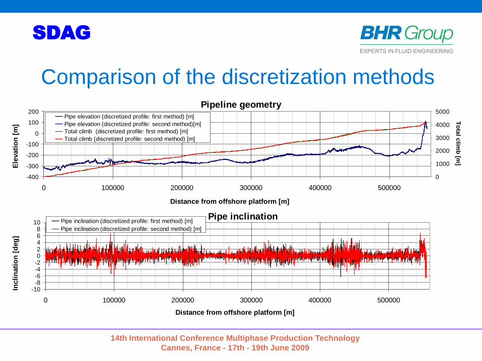
Comparison of the discretization methodsPipeline geometry
-400
-300
-200
-100
0
100
200
0 100000 200000 300000 400000 500000
Distance from offshore platform [m]
Ele
vati
on
[m
]
0
1000
2000
3000
4000
5000
To
tal c
limb
[m]
Pipe elevation (discretized profile: first method) [m]
Pipe elevation (discretized profile: second method)[m]
Total climb (discretized profile: first method) [m]
Total climb (discretized profile: second method) [m]
Pipe inclination
-10-8-6-4-202468
10
0 100000 200000 300000 400000 500000
Distance from offshore platform [m]
Incli
nati
on
[d
eg
]
Pipe inclination (discretized profile: first method) [m]
Pipe inclination (discretized profile: second method) [m]
14th International Conference Multiphase Production Technology
Cannes, France - 17th - 19th June 2009
SDAG
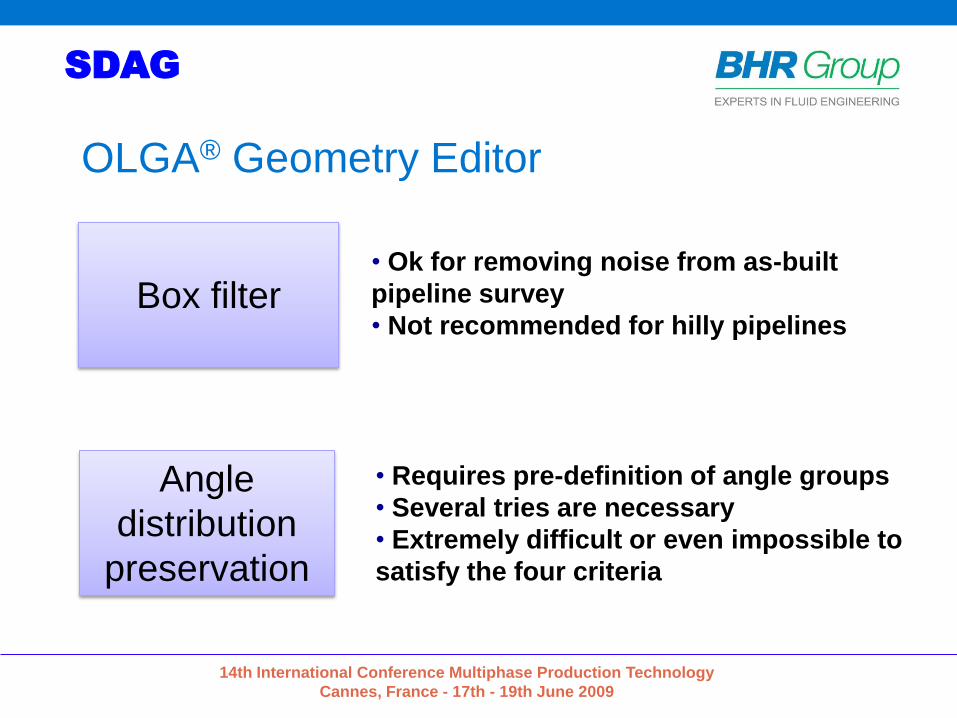
OLGA® Geometry Editor
Box filter
Angle
distribution
preservation
• Ok for removing noise from as-built
pipeline survey
• Not recommended for hilly pipelines
• Requires pre-definition of angle groups
• Several tries are necessary
• Extremely difficult or even impossible to
satisfy the four criteria
Related Documents