EEF APPRENTICES & SKILLS TECHNOLOGY CENTRE BIRMINGHAM UNIVERSITY SCHOOL OF ENGINEERING SKILLS TRAINING 2016 PIPE VICE PROJECT

Welcome message from author
This document is posted to help you gain knowledge. Please leave a comment to let me know what you think about it! Share it to your friends and learn new things together.
Transcript
EEF APPRENTICES & SKILLS TECHNOLOGY CENTRE
BIRMINGHAM UNIVERSITY SCHOOL OF ENGINEERING
SKILLS TRAINING 2016
PIPE VICE PROJECT
2
CONTENTS
1. JOINING INSTRUCTIONS
2. HOW TO FIND US
3. ABOUT EEF APPRENTICES AND SKILLS TECHNOLOGY CENTRE
4. SAFE WORKING PRACTICES
5. CNC GENERAL NOTES
6. DESIGN DRAWINGS
7. QUALITY ASSURANCE SHEET
3
1. JOINING INSTRUCTIONS
Group 1
8am to 4:30 pm, Monday 6 June 2016
8am to 4:30 pm, Tuesday 7 June 2016 Group 2
8am to 4:30 pm, Wednesday 8 June 2016
8am to 4:30 pm, Thursday 9 June 2016 Group 3
8am to 4:30 pm. Friday 10 June 2016
8am to 4:30 pm, Monday 13 June 2016 Group 4
8am to 4:30 pm, Tuesday 14 June 2016
8am to 4:30 pm, Wednesday 15 June 2016 Group 5
8 am to 4:30 pm, Thursday 16 June 2016
8 am to 4.30 pm, Friday 17 June 2016 Training will commence promptly at the times stated and it is important that you arrive on time and be dressed in your overalls, safety boots and safety glasses ready to begin training at your allotted times. We will supply: • Overalls • Safety glasses • Safety footwear
(Please bring a thick pair of socks with you as safety boots do not come in half sizes) • Refreshments
IMPORTANT INFORMATION FOR YOU - PLEASE READ BEFORE ATTENDING
• You will be issued with security passes that will open certain doors to allow access to the top
floor classrooms, workshop and toilets areas. New security passes will be issued to you daily. • Please ensure you sign in at reception each morning and sign out at the end of each day and
hand in your security pass each time you leave the building.
• Toilets are situated on the ground floor next to reception area. Toilet facilities are also available in the workshop area.
• The fire alarm is a loud continuous bell, on hearing the alarm please leave the building by the
nearest available exit and make your way to the front of the building and remain with your tutor until the all clear has been given and a fire register has been taken. Do not re-enter the building until instructed to do so by the Fire Brigade.
• The centre is a smoke free environment and smoking is only permitted in the designated
smoking area, which can be found at the rear of the building – please use ashtrays provided. • Break times are usually 10.30am and 2.45pm for 15 minutes in duration. A sandwich lunch will
be provided at 12.30pm on the days specified above. • When in the workshop – EYE PROTECTION, SAFETY BOOTS AND OVERALLS must be
worn AT ALL TIMES. • Do not operate or use any equipment in the workshop until you have been instructed on how to
use it safely.

4
2. HOW TO FIND US
EEF Apprentices & Skills Technology Centre Telephone: 0121 331 3930 Unit 3 Fax: 0121 331 3949 Nexus Point Website: www.eef.org.uk Gavin Way Birmingham B6 7AF From Birmingham City Centre Follow A34 north (Birchfield Road) After approximately 4 miles, exit onto the A453 (Aldridge Road) towards Kingstanding/Sutton Coldfield. In half a mile turn right onto Holford Drive, then take 1st exit on to Gavin Way. The EEF Technology Training Centre will then be on the right. Free Parking is available at the front of the building. From the M6 Take the A34 exit (Birmingham North) follow the A34 until the junction with A453 (Aldridge Road) take the left turn and follow the Aldridge Road. In half a mile turn right onto Holford Drive, and then take 1st exit on to Gavin Way. The EEF Technology Training Centre will then be on the right. Free Parking is available at the front of the building. Useful Travel numbers and Websites CENTRO: www.centro.org.uk 0121 200 2700 Travel West Midlands: www.travelwm.co.uk 0870 608 2608
5
3. ABOUT EEF APPRENTICES AND SKILLS TECHNOLOGY CENTRE
EEF Apprentices & Skills Technology Centre is a fully approved and licensed training provider. We sustain the highest tradition of engineering and manufacturing training excellence, playing a major role in strengthening the skills base of companies and our industry. We are approved by City and Guilds, EAL, the Chartered Institution of Environmental Health and the Institute of Leadership and Management. We are also regarded by the Learning Skills Council and Business Link, as a key player in the training and development of people within the engineering/manufacturing sector. Services offered by EEF Apprentices & Skills Technology Centre include:
Apprentice Selection and Recruitment
Craft Apprentices Training
Technician apprentice Training
Graduate and Undergraduate Training
Approved Electrical, Mechanical engineering/manufacturing/maintenance Training
CNC Programming and setter training
CAD Training
Approved Welder Training
Approved First Aid Training
Quality Training
Approved Folk Lift Truck and Overhead Crane Driver Training
Approved Health and Safety Training
Hydraulic and Pneumatic Training
I.T Training
Lean Manufacturing Training
Basic Workshop and Traditional Machining Skills Training
Power Press Safety Training
Approved Team leader/First Line Manager Awards.
Consider the Outstanding qualities of the Technology Centre: 1. We train people in smaller groups, including one to one support, for optimum impact. 2. We can adapt courses to match the customer’s priorities and the individual needs of the
learner. 3. We have the flexibility to run programmes in your own premises. 4. Our courses are genuinely hands on, combining theory with a structured practical approach. 5. Our staff are experienced engineers as well as qualified trainers 6. Our fees are highly competitive What’s more, you can rely on the quality of our advice on any aspect of you training needs. Our knowledge, and our experience, is comprehensive: as part of a leading national engineering organisation, we are continuously in touch with the latest developments and opportunities.
6
4. SAFE WORKING PRACTICES
Always wear safety equipment provided:
Safety Glasses
Overalls (done up to neck)
Safety Boots (laces tied)
ALWAYS ensure that long hair is tied back or covered
ALWAYS remove Jewellery - rings, bracelets etc. (They may get caught in the machine or on swarf)
ALWAYS keep aisles free from obstruction - ensure that exits can be reached safely
ALWAYS keep work area clean and tidy - Avoid slips trips and falls.
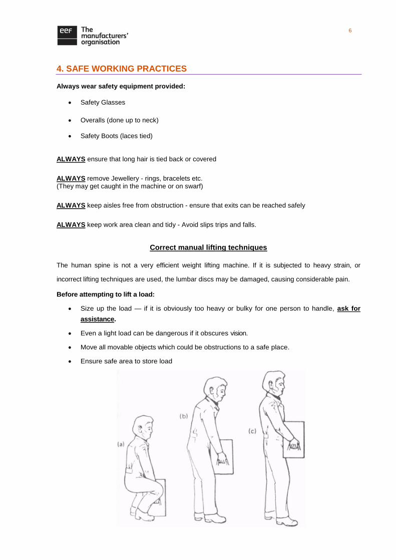
Correct manual lifting techniques
The human spine is not a very efficient weight lifting machine. If it is subjected to heavy strain, or
incorrect lifting techniques are used, the lumbar discs may be damaged, causing considerable pain.
Before attempting to lift a load:
Size up the load — if it is obviously too heavy or bulky for one person to handle, ask for
assistance.
Even a light load can be dangerous if it obscures vision.
Move all movable objects which could be obstructions to a safe place.
Ensure safe area to store load
7
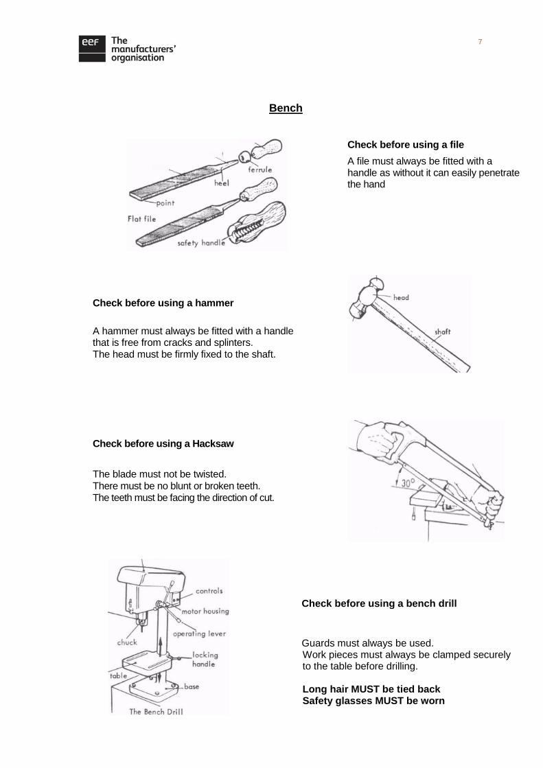
Check before using a Hacksaw
The blade must not be twisted.
There must be no blunt or broken teeth. The teeth must be facing the direction of cut.
Bench
Check before using a file
A file must always be fitted with a handle as without it can easily penetrate the hand
Check before using a hammer
A hammer must always be fitted with a handle that is free from cracks and splinters. The head must be firmly fixed to the shaft.
Check before using a bench drill
Guards must always be used. Work pieces must always be clamped securely to the table before drilling. Long hair MUST be tied back Safety glasses MUST be worn
8
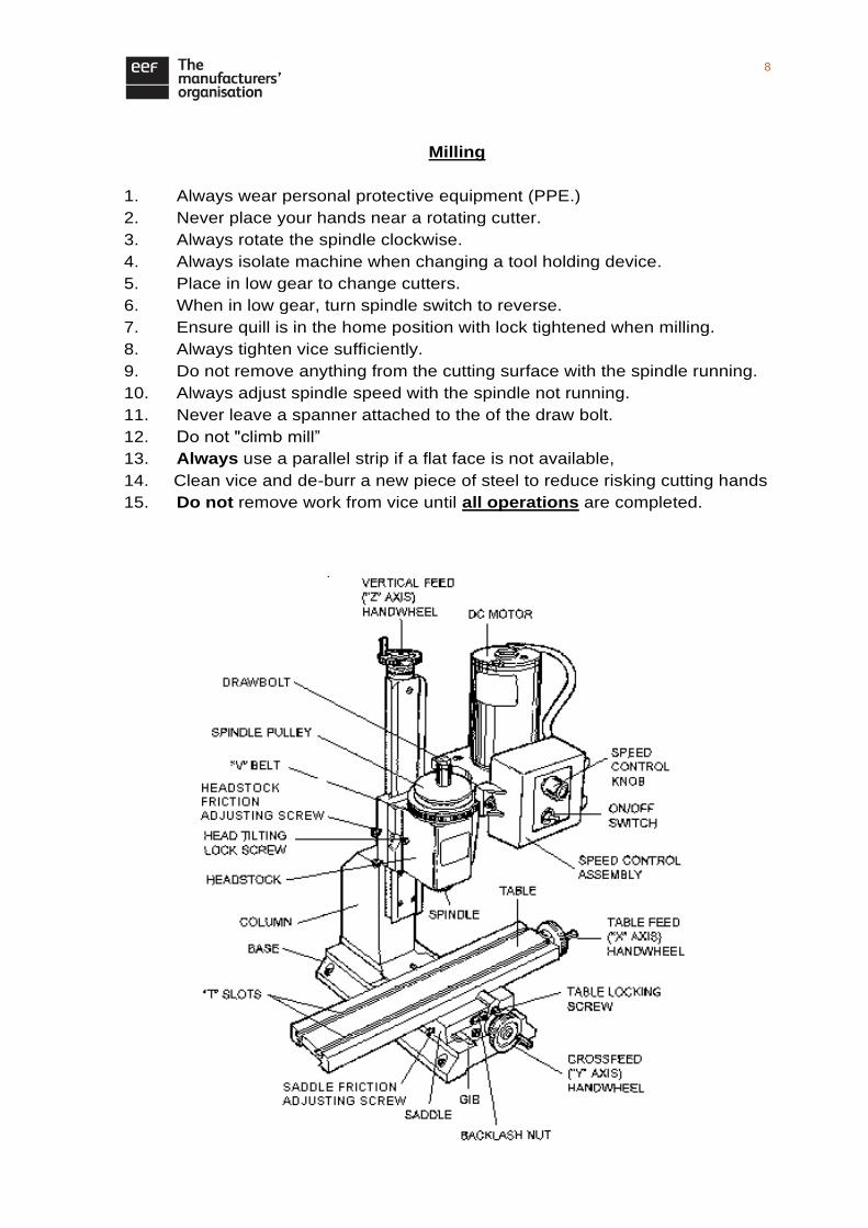
Milling
1. Always wear personal protective equipment (PPE.)
2. Never place your hands near a rotating cutter.
3. Always rotate the spindle clockwise.
4. Always isolate machine when changing a tool holding device.
5. Place in low gear to change cutters.
6. When in low gear, turn spindle switch to reverse.
7. Ensure quill is in the home position with lock tightened when milling.
8. Always tighten vice sufficiently.
9. Do not remove anything from the cutting surface with the spindle running.
10. Always adjust spindle speed with the spindle not running.
11. Never leave a spanner attached to the of the draw bolt.
12. Do not "climb mill”
13. Always use a parallel strip if a flat face is not available,
14. Clean vice and de-burr a new piece of steel to reduce risking cutting hands
15. Do not remove work from vice until all operations are completed.
9
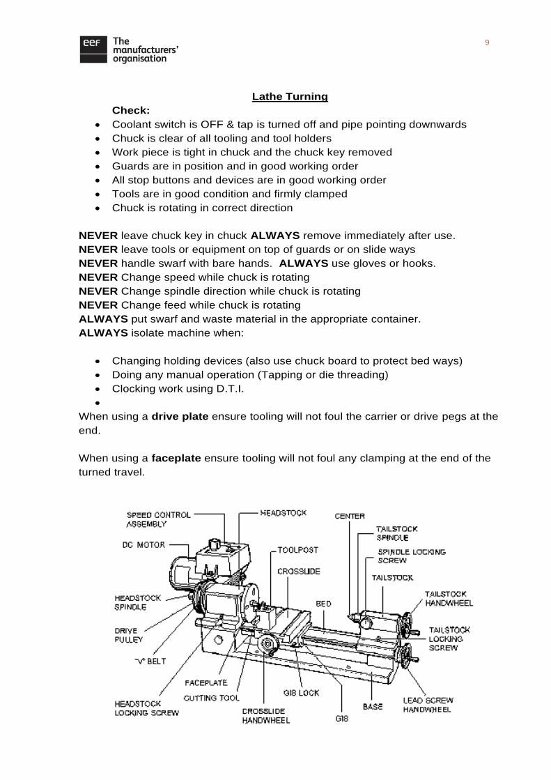
Lathe Turning
Check:
Coolant switch is OFF & tap is turned off and pipe pointing downwards
Chuck is clear of all tooling and tool holders
Work piece is tight in chuck and the chuck key removed
Guards are in position and in good working order
All stop buttons and devices are in good working order
Tools are in good condition and firmly clamped
Chuck is rotating in correct direction
NEVER leave chuck key in chuck ALWAYS remove immediately after use.
NEVER leave tools or equipment on top of guards or on slide ways
NEVER handle swarf with bare hands. ALWAYS use gloves or hooks.
NEVER Change speed while chuck is rotating
NEVER Change spindle direction while chuck is rotating
NEVER Change feed while chuck is rotating
ALWAYS put swarf and waste material in the appropriate container.
ALWAYS isolate machine when:
Changing holding devices (also use chuck board to protect bed ways)
Doing any manual operation (Tapping or die threading)
Clocking work using D.T.I.
When using a drive plate ensure tooling will not foul the carrier or drive pegs at the
end.
When using a faceplate ensure tooling will not foul any clamping at the end of the
turned travel.
10
5. CNC GENERAL NOTES
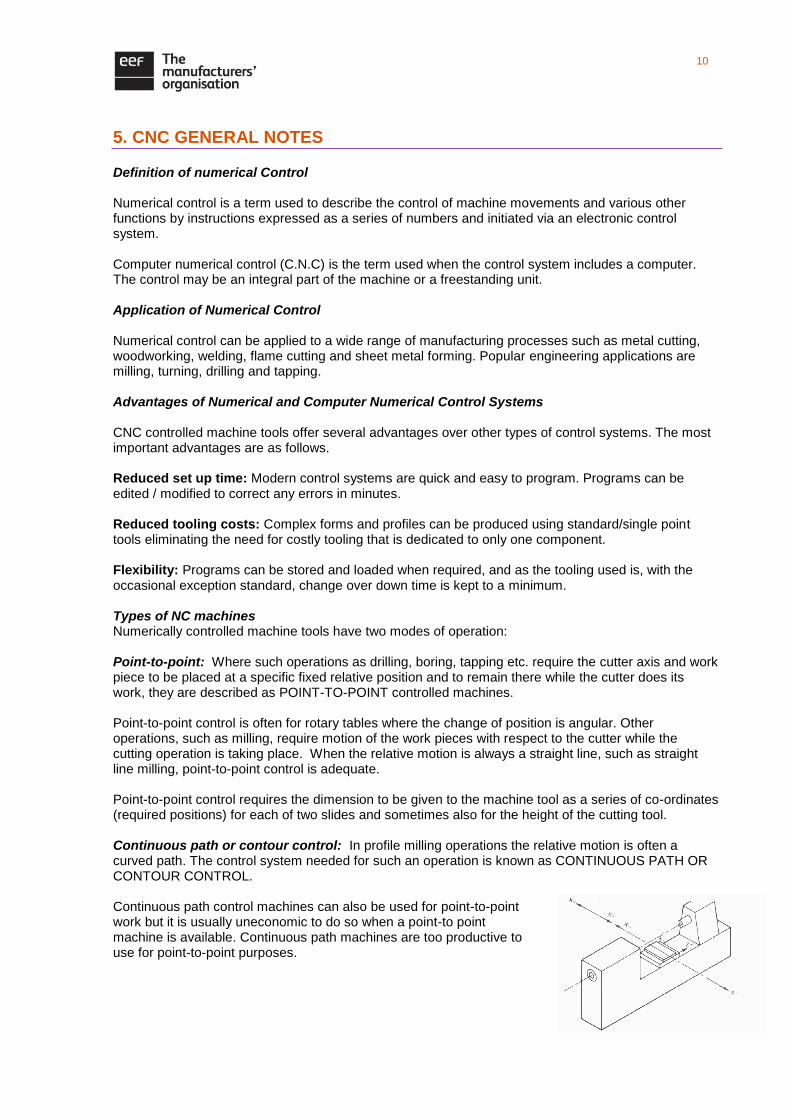
Definition of numerical Control Numerical control is a term used to describe the control of machine movements and various other functions by instructions expressed as a series of numbers and initiated via an electronic control system. Computer numerical control (C.N.C) is the term used when the control system includes a computer. The control may be an integral part of the machine or a freestanding unit. Application of Numerical Control Numerical control can be applied to a wide range of manufacturing processes such as metal cutting, woodworking, welding, flame cutting and sheet metal forming. Popular engineering applications are milling, turning, drilling and tapping. Advantages of Numerical and Computer Numerical Control Systems CNC controlled machine tools offer several advantages over other types of control systems. The most important advantages are as follows. Reduced set up time: Modern control systems are quick and easy to program. Programs can be edited / modified to correct any errors in minutes. Reduced tooling costs: Complex forms and profiles can be produced using standard/single point tools eliminating the need for costly tooling that is dedicated to only one component. Flexibility: Programs can be stored and loaded when required, and as the tooling used is, with the occasional exception standard, change over down time is kept to a minimum. Types of NC machines Numerically controlled machine tools have two modes of operation: Point-to-point: Where such operations as drilling, boring, tapping etc. require the cutter axis and work piece to be placed at a specific fixed relative position and to remain there while the cutter does its work, they are described as POINT-TO-POINT controlled machines. Point-to-point control is often for rotary tables where the change of position is angular. Other operations, such as milling, require motion of the work pieces with respect to the cutter while the cutting operation is taking place. When the relative motion is always a straight line, such as straight line milling, point-to-point control is adequate. Point-to-point control requires the dimension to be given to the machine tool as a series of co-ordinates (required positions) for each of two slides and sometimes also for the height of the cutting tool. Continuous path or contour control: In profile milling operations the relative motion is often a curved path. The control system needed for such an operation is known as CONTINUOUS PATH OR CONTOUR CONTROL. Continuous path control machines can also be used for point-to-point work but it is usually uneconomic to do so when a point-to point machine is available. Continuous path machines are too productive to use for point-to-point purposes.

11
Part Programming The expression ‘part program’ often causes confusion, since part is often thought to mean something which is not complete. However when used in the context of part programming or part program, the program is complete. The word part means component. Machine Axis Designation The machine axes, or planes in which the machine moves, are each identified by a letter: X, Y and Z on a milling machine and X, Z for a lathe. Z axis movement are always along the line of the rotating spindle. Preparatory Functions Preparatory functions, known as G codes, are used to set the conditions for, and the control of machining operations. The functions are identified by the letter G, followed by 2 digits. For example when G21 is called the machines measuring system will be in metric, G01 would be called to move the machine table or cutting tool in a straight line at a specified feed rate. Many G codes are standard across a range of machine tools however reference to a specific machine manual is always valuable, as code designation may vary depending on make and type. Many G codes are known as MODAL and once called remain active until cancelled, for example G40 will cancel G41 and 42. A NON-MODAL G code is only operative in the block (line) of code it is called, an example of which is G04 dwell. Miscellaneous Functions Miscellaneous or management functions are known as M codes. They are used to control functions that support and manage the machining operation. The functions are identified by the letter M and 2 digits. M code designations do vary depending on machine make and type so REMEMBER WHEN WRITING A PART PROGRAM, ONLY ONE M CODE CAN BE CALLED PER BLOCK (LINE).
12
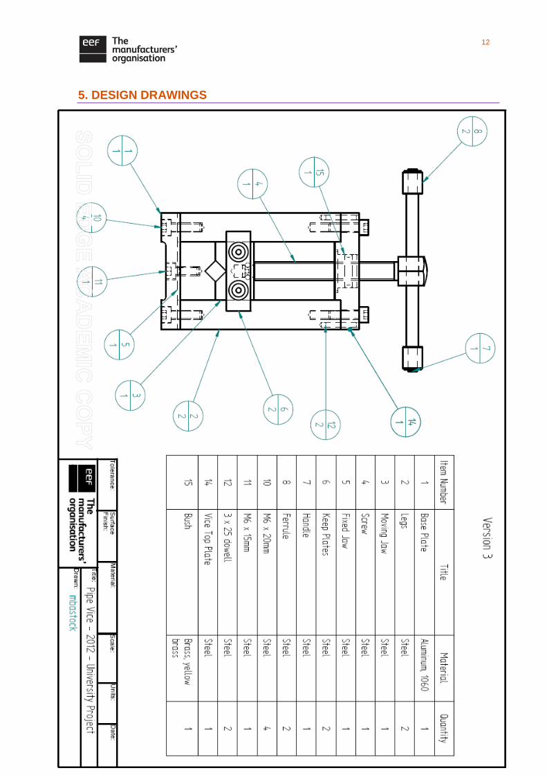
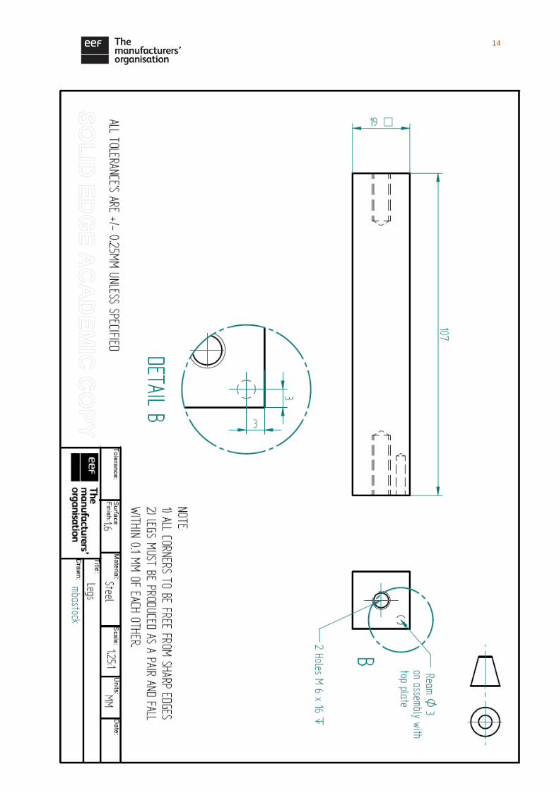
5. DESIGN DRAWINGS

13
14
15
16
17
18
19
20
21
22
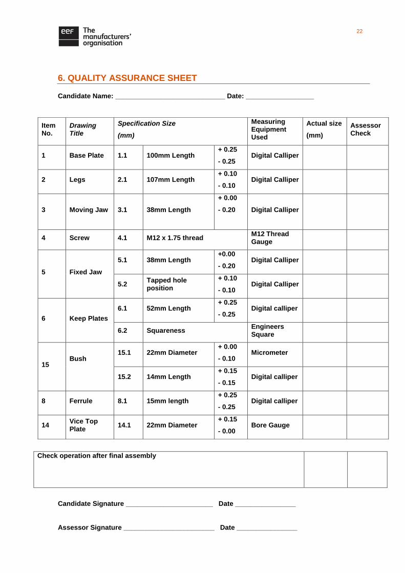
6. QUALITY ASSURANCE SHEET
Candidate Name: _____________________________ Date: __________________
Check operation after final assembly
Candidate Signature _______________________ Date ________________
Assessor Signature ________________________ Date ________________
Item No.
Drawing Title
Specification Size
(mm)
Measuring Equipment Used
Actual size
(mm)
Assessor Check
1 Base Plate 1.1 100mm Length + 0.25
- 0.25 Digital Calliper
2 Legs 2.1 107mm Length + 0.10
- 0.10 Digital Calliper
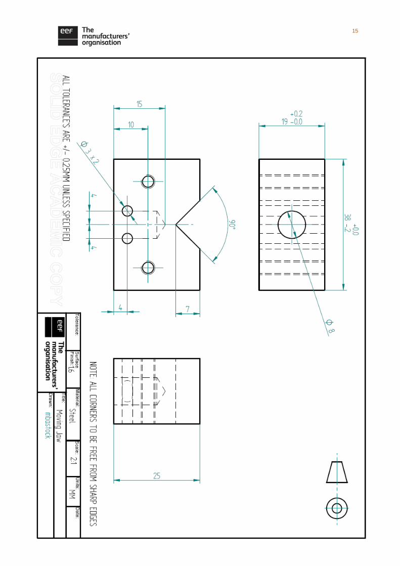
3 Moving Jaw 3.1 38mm Length
+ 0.00
- 0.20
Digital Calliper
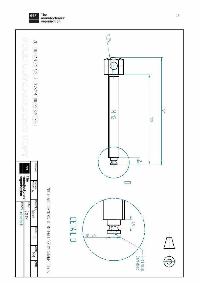
4 Screw 4.1 M12 x 1.75 thread M12 Thread Gauge
5
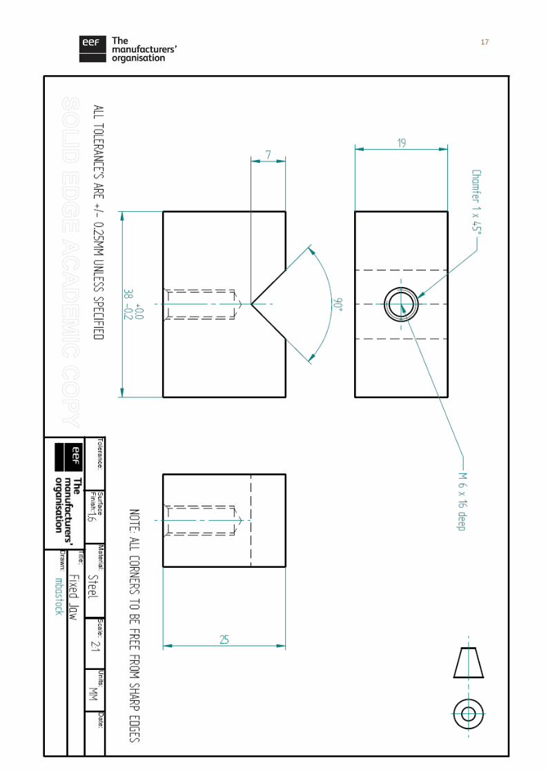
Fixed Jaw
5.1 38mm Length +0.00
- 0.20 Digital Calliper
5.2 Tapped hole position
+ 0.10
- 0.10 Digital Calliper
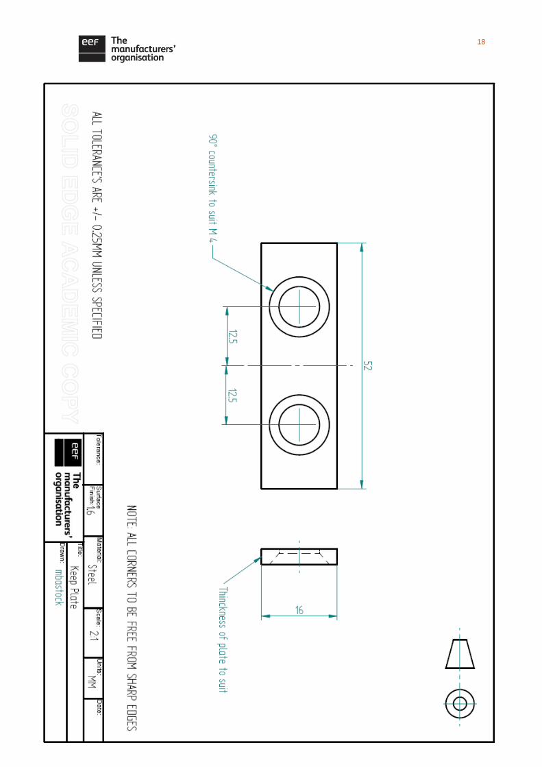
6 Keep Plates
6.1 52mm Length + 0.25
- 0.25 Digital calliper
6.2 Squareness Engineers Square
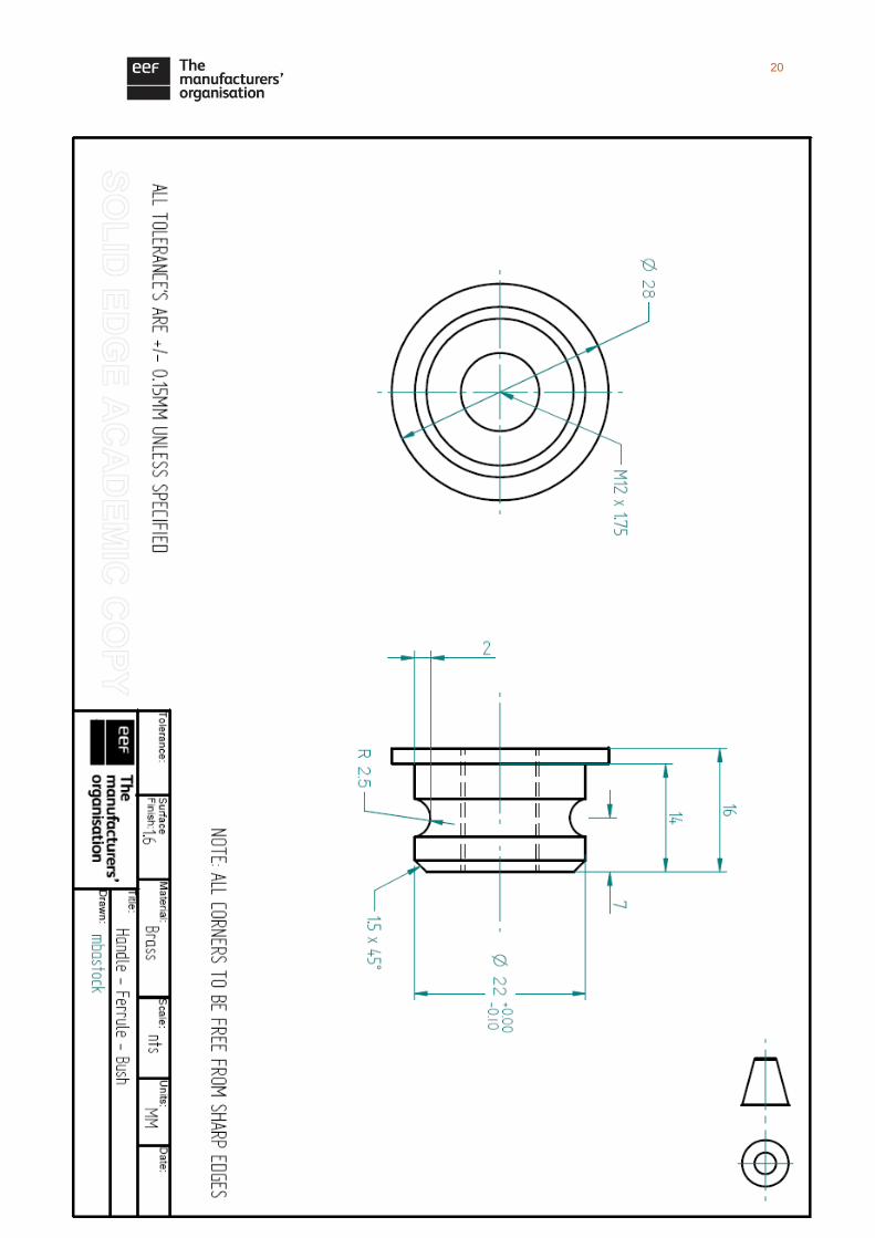
15 Bush
15.1 22mm Diameter + 0.00
- 0.10 Micrometer
15.2 14mm Length + 0.15
- 0.15 Digital calliper
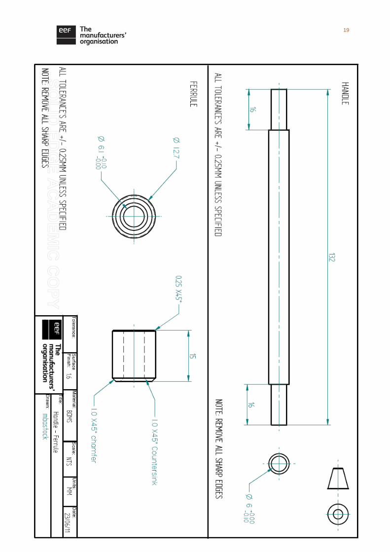
8 Ferrule 8.1 15mm length + 0.25
- 0.25 Digital calliper
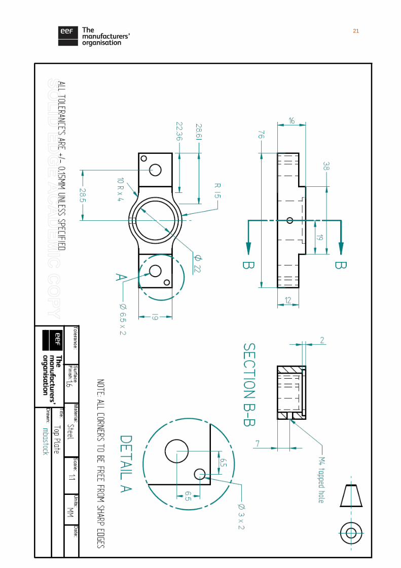
14 Vice Top Plate
14.1 22mm Diameter + 0.15
- 0.00 Bore Gauge
Related Documents