2 2 3 8 1 P I teknillinen korkeakoulu kniikan osasto • N:o6 liversity of Technology of Civil Engineering >ly and Sewerage Post Graduate Course in Water Engineering 1979 —81 in co-operatiort with Ministry for Foreign Affairs of Finland Department for International Development Co-operation Kayombo W.R.C. Pipe Materials in Transmission Mains l w Tampere 1981 UDK 628.14 ISBN 951-720-584-8 ISSN 0357-8860

Welcome message from author
This document is posted to help you gain knowledge. Please leave a comment to let me know what you think about it! Share it to your friends and learn new things together.
Transcript
2 2 3
8 1 P I
teknillinen korkeakoulu kniikan osasto
•
N:o6 liversity of Technology of Civil Engineering
>ly and Sewerage Post Graduate Course in Water Engineering 1979 —81
in co-operatiort with
Ministry for Foreign Affairs of Finland Department for International Development Co-operation
Kayombo W.R.C.
Pipe Materials in Transmission Mains
lw Tampere 1981
UDK 628.14 ISBN 951-720-584-8 ISSN 0357-8860
3<3
Tampereen teknillinen korkeakoulu Rakennustekniikan osasto Vesitekniikka
223 S I P
Tampere University of Technology Department of Civil Engineering Water Supply and Sewerage Post Graduate Course in Water Engineering 1979
#
N:o6
—81
in co-operation with Ministry for Foreign Affairs of Finland Department for International Development Co-operation
Kayombo W.R.C.
Pipe Materials in Transmission Mains UBRMW n .prpnce Centre
Tampere 1981 UDK 628.14 ISBN 951-720-584-8 ISSN 0357-8860
PIPE MATERIALS IN TRANSMISSION MAINS
by C.R.W. Kayombo
A thesis submitted for a
degree of Master of Science
(Engineering) at the Tampere
University of Technology,
Finland
March 1981
TABLE OF CONTENTS
ABSTRACT
DEVELOPMENT OF PIPES 1
1.1 History of Pipes 1
1.2 Community Water Supply 2
1.3 Transmission 3
FLUID FLOW AND PIPE MATERIAL REQUIREMENTS 4
2.1 Formulae in Fluid Transport 4
2.2 Material Requirements 7
2.3 Problems Encountered in Pipelines 7
2.3.1 Forces on Pipelines 7
Soil 7
Traffic 9
Water Hammer 9
Thrust 12
Others 13
2.3.2 Corrosion 13
2.3.3 Health Aspects 18
PIPE MATERIALS 19
3.0 Development 19
3.1 Plastics 19
3.2 ' Prestressed Contrete 24
3.3 Asbestos Cement 25
3.4 Cast Iron 28
3.5 -Steel 30
3.6 Engineering Properties of Pipe 33
Materials
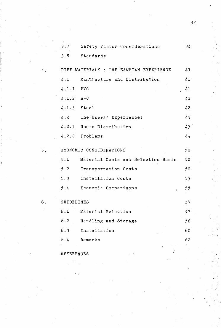
3.7 Safety Factor Considerations
3.8 Standards
PIPE MATERIALS : THE ZAMB.IAN EXPERIENCE
4.1 Manufacture and Distribution
4.1.1 PVC
4.1.2 A-C
4.1.3 Steel
4.2 The Users' Experiences
4.2.1 Users Distribution
4.2.2 Problems
ECONOMIC CONSIDERATIONS
5.1 Material Costs and Selection Basis
5.2 Transportation Costs
5.3 Installation Costs
5.4 Economic Comparisons
GUIDELINES
6.1 Material Selection
6.2 Handling and Storage
6.3 Installation
6.4 Remarks
REFERENCES
ABSTRACT
In this paper the author has confined himself to
a discussion on pipes in rising mains. The manufacturing
process and characteristics of the different pipe materials
have been covered. The study also looks at some problems
encountered in pipelines. A brief survey of the use of
different pipe materials (viz. PVC, A-C and Steel) in
Zambia has been included. The paper ends with guidelines
to the use of different pipe materials in Zambia taking
into account previous experiences.
1
].. DEVELOPMENT OF PIPES
1.1 Historical Factors
Water Supply Engineering originated with the growth of
ancient towns or trade centres. Inspite of the time at
which they were constructed the structures were of a
complex nature and remnants of some of them are monuments
of great magnitude. Some of the notable ones are the
aqueducts of Rome and her empire. Indeed Sextus Julius (5)
Frontinus who was water commissioner of Rome in AD 97
reported the existence of nine aqueducts supplying water
to Rome. These varied in length from 10 to over 80 km and
varying in cross section from 0.5 to 5sq.m. Clemeus
( 5 ) Herschet a hydraulic engineer (1842-1930) estimated
the total capacity of the aqueducts at over 400,000m3/d.
However, quality control in water supply is of recent
origin. It too originated with the growth of cities.
Developments in science and engineering in the eighteenth
and nineteenth centuries created industrial centres which
attracted people. The sanitary facilities of these mush
rooming towns were soon over stretched. Whereas before
water was simply drawn from streams and wells, then
distributed through stand pipes, the fatigue of fetching
water from these stand pipes caused the inhabitants to
restrict its use to the most important usage - food -
neglected everything else including cleanliness. . .
2
There was therefore need to develop a system of distributing
safe water and with it, the disposal of wastewater. Although
cities were provided with drainage systems fecal and other
wastes were not allowed into these systems. They left the
drainage systems to carry storm water only. Surprisingly
this practice continued well into the nineteenth century.
Eventually human excrement was allowed into these open storm
drains. It was this filthy sight and general unhygienic
conditions of this system that notable characters like
Sir Edwin Chadwick (a lawyer by profession 18^2) called for
(5 ) a crusader for health. In 181+9 Dr. John Snow demonstrated
the role of fecal pollution of drinking water in the
epidemicity of cholera.
Eventually John Roe accepted Chadiwick's advice and
constructed sewer lines of vitrified tile pipe. Thus
industrial developments coupled with increase in the demand
for proper sanitation forced the ancient scientists and
engineers to improve on the methods of water supply and
wastewater disposal. This required the use of pipes for
the transmission and distribution in case of,water and for
the collection and transmission in case of wastewater.
1.2 Community Water Supply
Water is supplied to municipalities for many purposes such
as (l) drinking, (2) bathing and laundry, (3) for watering
lawns and gardens, (U) industrial use,' (5) f° r fire fighting
and (6) for wastewater removal. To provide for all these
3
varying uses the supply must be satisfactory in quality and
quantity. It must also "be cheap to the user. In Zambia
150 Ipcd is used frequently in designing community water
supply.
Therefore, when a choice of what pipe material to use is
to be made consideration should be given as to the total
cost of the pipes, including the transportation and
installation costs; their capability to transmit the desired
quantity and their chemical effect, if any, on the water.
Masonry and most metal pipes transmitting water to communities
may be attacked by the water they convey and thereby change
its quality. Therefore every designer should adjust the pipe
materials used to the quality of the water, or adjust the
quality of the water to the pipe material used.
1.3 Transmission
Water supply conduits transporting water from the source to
the community form an important link. Conduits may be
designed for open channel or closed conduit pressure flow.
Open channels follow the hydraulic grade line or dug out
canals. On the other hand pressure conduits may depart from
the hydraulic grade line and cut through valleys and hills.
Size and shape of the conduit are determined by hydraulic and
economic factors. The same is true when one has to decide
on which pipe material to be used for any given scheme.
k
2. FLUID FLOW AND PIPE MATERIAL REQUIREMENTS
The structural design and indeed the choice of pipe material
•will be governed by factors such as the hydraulics of the
flow system and the prevailing local conditions. Usually
the capacities of commercial pipes vary considerably from
theoretical values. It is therefore a common practice to
design pipeline system for maximum discharges at non-silting
and non-erodable velocities to minimize friction losses.
The local conditions will vary from place to place and the
magnitude will depend on factors such as soil type,
dissolved chemicals in water, traffic, etc.
2.1 Formulae in Fluid Transport
Resistance to flow, which is related to the pipe material
plays an important role in pipeline design. And in rising
(transmission) mains this frictional resistance is more
important than resistance caused by appurtenances. In dealing
with this problem a number of rational formulae and their
solutions have been developed. Starting off with the
original Chezy's proposal (1775) to the present Darcy Weiback.
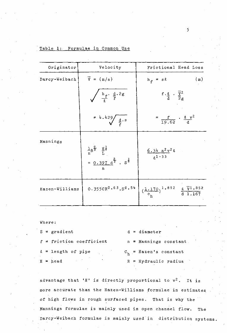
In Table 1 three common formulae have been tabulated-
In field practice, however, the engineer is free to choose
the formulae which suits his conditions. For many practical
conditions the Hazen-Williams formulae is popular and well
documented. It is also reasonably accurate over a range
of pipe diameters and flows. The weakness lies in the
estimates of C in the absence of measurements of head loss
and velocity. On the other hand Mannings formulae has the
5
Table 1: Formulae in Common Use
Originator Velocity Fractional Head Loss
Darcy-Weibach V = ( m / s )
h . d . 2 ,
X f
= k
•h2fl-
h , = s £
f ._£ d
(m)
r 2 g
£ v< 1 9 . 6 2 d
M a n n i n g s
L ^R;
= 0 - 3 9 7 d £
6.3U n 2 v 2 £
1 - 3 3
Hazen-Williams 0.355CR°-63.S°-51t /l.lTOx1'852 £ yi.852 * c. J d I.167 h
Where:
S. = gradient
f = friction coefficient
£ = length of pipe
H = head
d =
n =
Ch =
R =
diameter
Mannings constant
Hazen's constant
Hydraulic radius
advantage that '-H' is directly proportional to v2 . It is
more accurate than the Hazen-Williams formulae in estimates
of high flows in rough surfaced pipes. That is why the
Mannings formulae is mainly used in open channel flow. The
Darcy-Weibach formulae is mainly used in distribution system
6
Its advantage is that for constant 'f' H is directly-
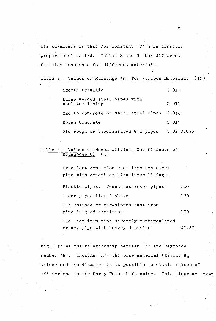
proportional to 1/d. Tables 2 and 3 show different
formulae constants for different materials.
Table 2 : Values of Mannings 'n' for Various Materials (15)
Smooth metallic 0.010
Large welded steel pipes with
coal-tar lining 0.011
Smooth concrete or small steel pipes 0.012
Rough Concrete 0.017
Old rough or tuberculated G.I pipes 0.02-0.035
Table 3 : Values of Hazen-Williams Coefficients of Roughness Ch ( 3)
Excellent condition cast iron and steel
pipe with cement or bituminous linings.
Plastic pipes. Cement asbestos pipes 140
Older pipes listed above 130
Old unlined or tar-dipped cast iron
pipe in good condition 100
Old cast iron pipe severely turberculated
or any pipe with heavey deposits 4-0-80
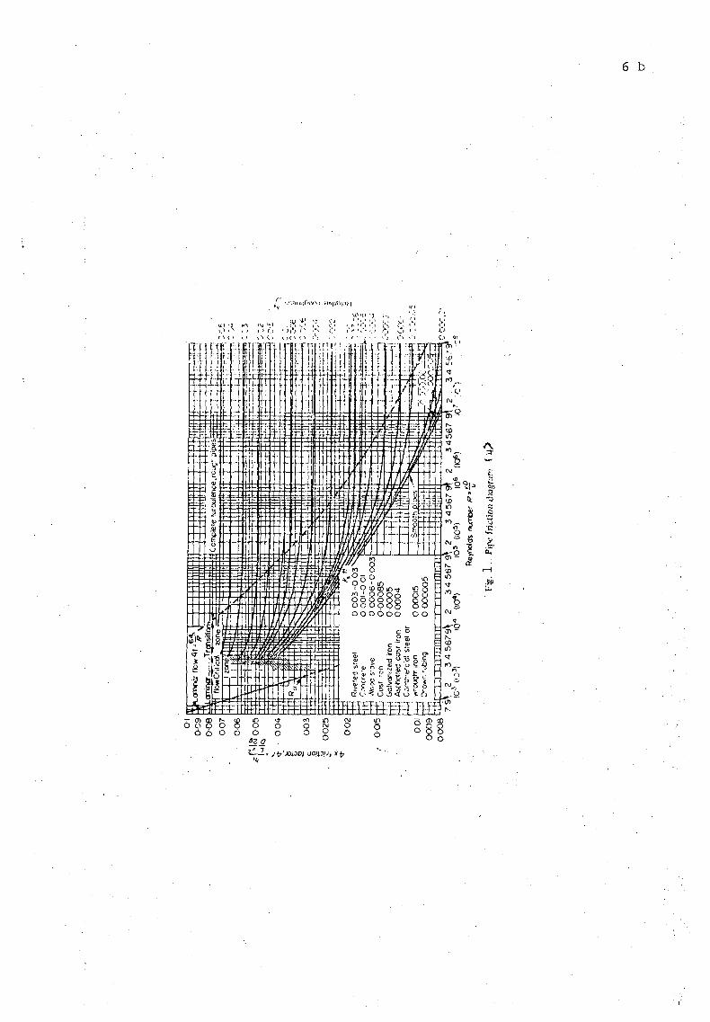
Fig.l shows the relationship between 'f' and Reynolds
number 'R1. Knowing 'R', the pipe material (giving Ks
value) and the diameter is is possible to obtain values of
'f' for use in the Darcy-Weibach formulae. This diagrame known
6 b
\';;n u jf>iinj ;i/\|iD|;vi
WO -J : ;t:; :-; x y ;•:
as the Hunder House resistance diagram is used for flow
in uniform conduct.
2.2 Material Requirements
Before consideration is made as to what type of pipe to be
used the first step is determining the total consumption.
The hydraulic and economic factors will follow in deciding
the minimum workable size of pipe. Structurally the pipes
must overcome the following forces:
1) Temperature-induced expansion and contraction.
2) External loads in the form of traffic, backfill and
their own weight between supports.
3) Unbalanced pressures at bends, contractions and
closures.
L,) Water hammer
5) Internal pressures equal to the full head of water
2.3 Problems Commonly Encountered in Pipelines
2.3.1 Forces on Pipes
Soil: Buried pipes have to cope with, among other
things, crippling of the walls caused by external soil
pressure. This may be crushing or buckling. The pipe may
also suffer from deflection or change of diameter because
of the compression of the soil. In pipeline design ring
deflection is often very important. Crackling is primarily
a function of ring deflection. Marston calculated
maximum load on buried pipes and came up with a formulae for
the load on buried pipes. The formulae is in imperial units,
8
It is therefore necessary to convert the dimensions
whenever using the formulae
W = C/B2
where W = load on pipe lb/ft
C = load coefficient as function of depth, trench
width and type of soil
/ = density of backfill lb/ft
B = width of trench at top of pipe (ft)
Expansive soils have aperculiar property. By definition
expansive soils are soils that swell (upon wetting), or
shrink (upon drying). The process is generally referred
to as volume changes. Various clays (e.g. kaolinites,
montmorillonites, etc.) behave this way. The following f
characteristics may indicate a potential expansive soil
if it:
- becomes very hard upon drying and also cracks.
- becomes very sticky upon wetting
- absorbs water slowly
- fine grained.
These soils can damage structures on or within them. In
underground piping the failure is more of beam break in
strong-rigid type pipes and ring-crash in weak rigid type
pipes. Construction of a trench for the installation of
a pipeline attracts water from the surroundings into the
trench. Shallow cover over the pipe in expansive soils
which thereafter suffer from long dry periods may promote
pipe damage because of pressure differences above and below
9
the pipe. Damage to the external pipe coating may occur
due to shrinkage. As the soil shrinks it grips the coating
and peels it off, thus exposing the pipe.
Traffic:
Traffic loads are a nuisance to pipelines. In general
'weak' pipes like plastics and asbestos cement pipes have to
be protected with either concrete pipes or cast iron pipes
whenever they encounter roads or railways. Accordint to
studies undertaken by the Transport and Road Research
(12) Laboratory , most severe loads on pipes occur during
the construction period when heavy trucks transverse
pipelines. It was also established that the impact factor
increases with speed of vehicles. But the relationship
between impact factor and speed was found to be independent
of pipe size, type of pipe and backfill material.
Water Hammer:
Regardless of the pipe material a water hammer can occur in-
any pipeline as a result of a rapid change in flow. This
induces a pressure wave which hauls back and forth. Typical
causes of sudden change of fluid velocity are:
l). Quick opening of line valve
2) Quick closing of a line valve
3) Sudden starting of a pump
h) Sudden stopping of a pump.
When for example flow in a pipeline is suddenly stopped, in
less time than is required for a pressure wave to make one
10
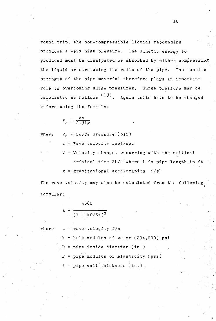
round trip, the non-compressible liquids rebounding
produces a very high pressure. The kinetic energy so
produced must be dissipated or absorbed by either compressing
the liquid or stretching the walls of the pipe. The tensile
strength of the pipe material therefore plays an important
role in overcoming surge pressures. Surge pressure may be
(13) calculated as follows . Again units have to be changed
before using the formula:
P = a V
s 2.31g
where Ps = Surge pressure (psi)
a = Wave velocity feet/sec
V = Velocity change, occurring with the critical
critical time 2L/a where L is pipe length in ft-
g = gravitational acceleration f/s2
The wave velocity may also be calculated from the following.
formular:
-4660
a (1 + KD/Et)*
where a = wave velocity f/s
K = bulk modulus of water (294,000) psi
." D = pipe inside diameter (in. )
E = pipe modulus of elasticity (psi)
t = pipe wall thickness (in.)
11
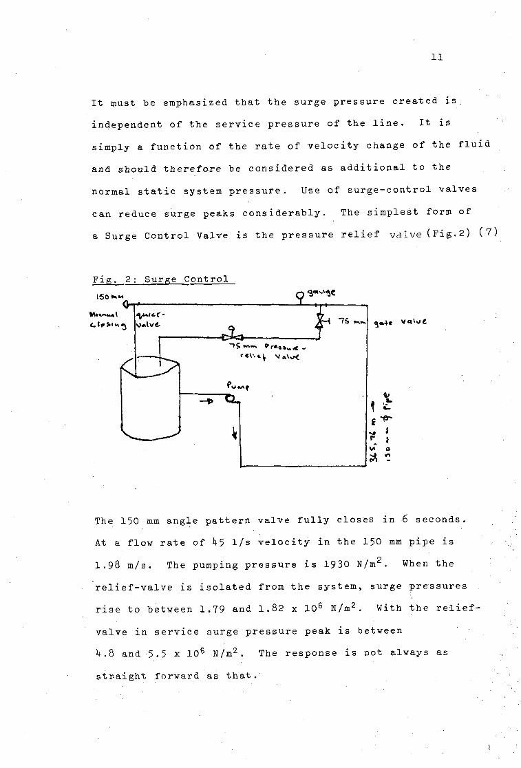
It must be emphasized that the surge pressure created is
independent of the service pressure of the line. It is
simply a function of the rate of velocity change of the fluid
and should therefore be considered as additional to the
normal static system pressure. Use of surge-control valves
can reduce surge peaks considerably. The simplest form of
a Surge Control Valve is the pressure relief valve (Fig.2) (7)
Fig. 2: Surge Control
G-T-
VJ-Avt
C^O-
;r— AH -76 ̂ m
XL.
k
g»4« vo^e
0/
» • - * •
^ i
vi o
The 150 mm angle pattern valve fully closes in 6 seconds.
At a flow rate of h5 1/s velocity in the 150 mm pipe is
1.98 m/s. The pumping pressure is 1930 N/m2. When the
relief-valve is isolated from the system, surge pressures
rise to between 1.79 and 1.82 x 10 6 N/m2. With the relief-
valve in service surge pressure peak is between
k.8 and 5.5 x 10⁶ N/m2. The response is not always as
straight forward as that.
*
12
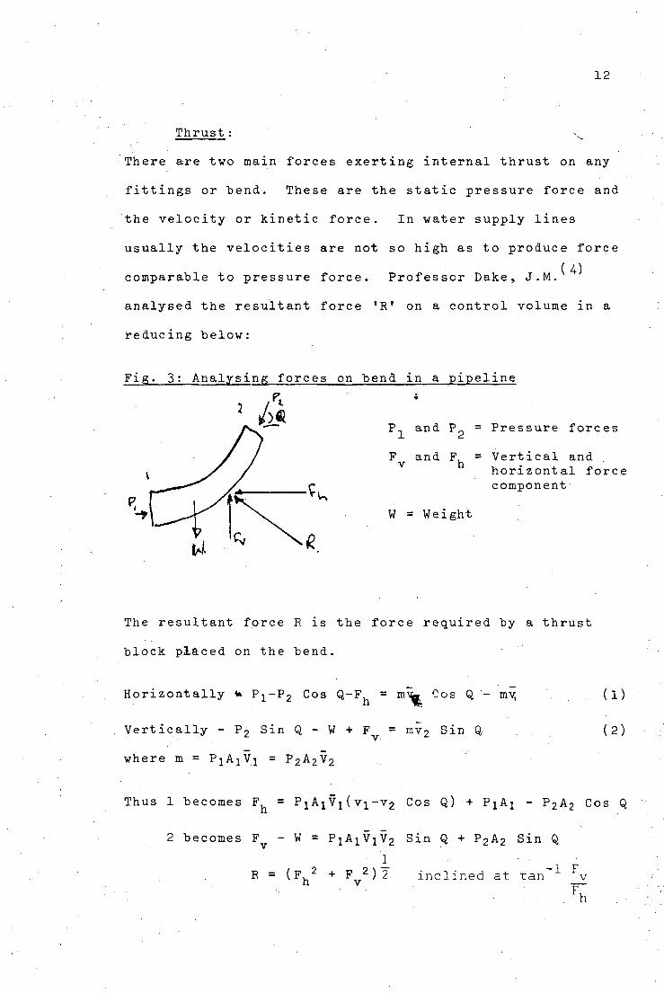
Thrust: • v . .
There are two main forces exerting internal thrust on any
fittings or bend. These are the static pressure force and
the velocity or kinetic force. In water supply lines
usually the velocities are not so high as to produce force
( A) comparable to pressure force. Professor Dake, J.M.
analysed the resultant force 'R' on a control volume in a
reducing below:
Fig. 3: Analysing forces on bend in a pipeline
P.. and P = Pressure forces
F and F, = Vertical and horizontal force component
W = Weight
The resultant force R is the force required by a thrust
block placed on the bend.
Horizontally <+ pi - p2 C o s Q-Fh = m ^ " o s Q ~ mvi
Vertically - P2 Sin Q - W + F = mv2 Sin Q
where m = PiAjV^ = P 2A 2V 2
(1)
(2)
Thus 1 becomes F = P 1A 1V 1(v 1-v 2 Cos Q) + PiAi - P2A2 Cos Q
2 becomes F - W = P ^ V Y ^ Sin Q + P2A2 Sin Q
R = ( F . 2 + F 2)2 inclined at tan -1 Fv
13
Others:
In some places other external forces such as those caused
by earthquakes are common. T.M. Mikaoka reports on some
damages caused by earthquakes in Japan. See Table k. Other
forces may be freezing of water in pipes especially in cold
climates. This usually is due to either to (a) pipes not
buried sufficiently deep, or (b) above-ground-surface pipes
insufficiently protected. The water may be melted by either
electrical thawing or using steam.
2 . k.2 Corrosion.
Corrosion has long been a concern to the water works and the
pipe industry. Despite the technological advances that
have reduced the susceptability of pipes to corrosion the
problem has continued to be a serious and costly one.
Indeed there are many factors involved when talking of the
corrosive quality of water. Each case must be examined
individually. Metalic pipes are the principal targets of
corrosion.
Theory of Corrosion
Basically the highly complex phenomenon of corrosion is
analogous to a dry-cell battery. Most common dry-cells are
made up of carbon and zinc electrodes separated by an
electrolyte. There is chemical reduction at the zinc
(cathode) electrode, and chemical oxidation at the carbon
(anode) electrode. Most metals have small amounts of
impurities. In addition the surfaces are not homogenous,
but have in essence, microcells. The exposure of metals to
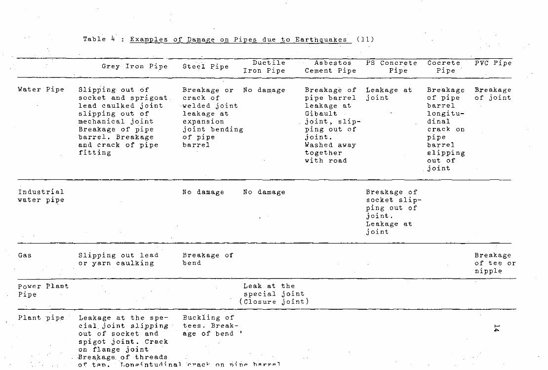
Table h : Examples of Damage on Pipes due to Earthquakes (11)
Grey Iron Pipe Steel Pipe Duct ile Iron Pipe
Asbestos Cement Pipe
PS Concrete Pipe
Cocrete Pipe
PVC Pipe
Water Pipe Slipping out of socket and sprigoat lead caulked joint slipping out of mechanical joint Breakage of pipe barrel. Breakage and crack of pipe fitting
Breakage or No damage crack of welded joint leakage at expansion joint bending of pipe barrel
Breakage of pipe barrel leakage at Gibault joint , slipping out of j oint. Washed away together with road
Leakage at j oint
Breakage of pipe barrel longitudinal crack on pipe barrel slipping out of joint
Breakage of joint
Industrial water pipe
No damage No damage Breakage of socket slipping out of joint. Leakage at j oint
Gas Slipping out lead or yarn caulking
Breakage of bend
Breakage of tee or nipple
Power Plant Pipe
Leak at the special joint (Closure joint)
Plant pipe Leakage at the special joint slipping out of socket and spigot joint. Crack on flange joint •Breakage of threads of tan. T.ono-intud'ina'l o->*acL'
Buckling of tees. Breakage of bend '
o n • n i n e b f l r r p l
15
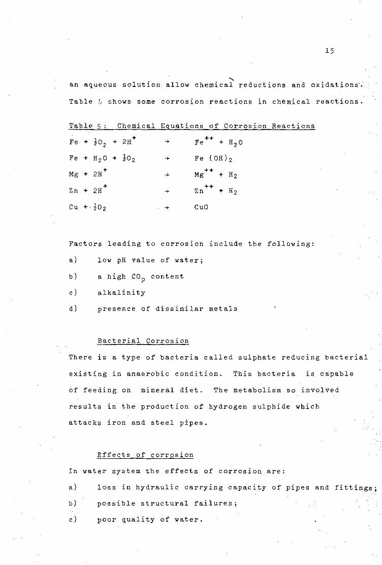
an aqueous solution allow chemical reductions and oxidations
Table 5 shows some corrosion reactions in chemical reactions
Table 5 : Chemical Equations of Corrosion Reactions
Fe + g02 + 2H+ -*• Fe + + + H20
Fe + H20 + 502 -> Fe (0H) 2
Mg + 2H+ -*- Mg + + + H2
Zn + 2H -*- Zn + H2
Cu + |0 2 -*• CuO
Factors leading to corrosion include the following:
a) low pH value of water;
b) a high C0p content
c) alkalinity
d) presence of dissimilar metals
Bacterial Corrosion
There is a type of bacteria called sulphate reducing bacterial
existing in anaerobic condition. This bacteria is capable
of feeding on mineral diet. The metabolism so involved
results in the production of hydrogen sulphide which
attacks iron and steel pipes.
Effects of corrosion
In water system the effects of corrosion are:
a) loss in hydraulic carrying capacity of pipes and fittings;
b) possible structural failures;
c) poor quality of water.
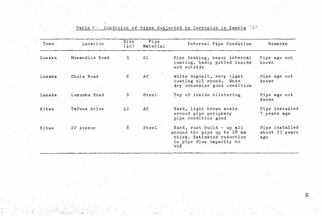
Table 6 ; Condition of Pipes Subjected to Corrosion in Zambia ' 1?
Town Location / • \ ., . • , Internal Pipe Condition Remarks (in) Material
Lusaka Musandile Road 3 Gl Pipe leaking, heavy internal Pipe age not coating, badly pitted inside known and outside
Lusaka Chula Road 6 AC White deposit, very light Pipe age not coating all round, When known dry otherwise good condition
Lusaka Lumumba Road 8 Steel Top of inside blistering Pipe age not known
Kitwe Tafuna Drive 12 AC Hard, light brown scale Pipe installed around pipe periphery 7 years ago pipe condition good
Kitwe 22 Avenue 8 Steel Hard, rust build - up all Pipe installed around the pipe up to 18 mm about 23 years thick. Estimated reduction ago in pipe flow capacity to ko%
a\
IT
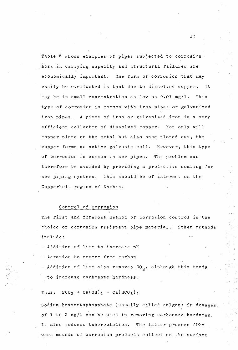
Table 6 shows examples of pipes subjected to corrosion.
Loss in carrying capacity and structural failures are
economically important. One form of corrosion that may
easily be overlooked is that due to dissolved copper. It
may be in small concentration as lov as 0.01 mg/1. This
type of corrosion is common with iron pipes or galvanized
iron pipes. A piece of iron or galvanized iron is a very
efficient collector of dissolved copper. Not only will
copper plate on the metal but also once plated out, the
copper forms an active galvanic cell. However, this type
of corrosion is common in new pipes. The problem can
therefore be avoided by providing a protective coating for
new piping systems. This should be of interest on the
Copperbelt region of Zambia.
Control of Corrosion
The first and foremost method of corrosion control is the
choice of corrosion resistant pipe material. Other methods
include:
- Addition of lime to increase pH
- Aeration to remove free carbon
- Addition of lime also removes C0 ?, although this tends
to increase carbonate hardness.
Thus: 2C02 + Ca(0H)2 + Ca(HC0 3) 2
Sodium hexametaphosphate (usually called calgon) in dosages
of 1 to 2 mg/1 can be used in removing carbonate hardness.
It also reduces tuberculati on. The latter process fro.m
when mounds of corrosion products collect on the surface
18
of metal:
- avoid having two metals with a high electropotential
difference
- coatings and linings of pipes will prevent both anodic
and cathodic reactions
Since bacterial corrosion can also occur from outside
protective coating (e.g. with bitumen) will help prevent
this. Also packing gravel or sand outside will free drain
water and thereby prevent anaerobic corrosion.
2..U.3 Health Aspects '"';'
Although lead pipes are used in the distribution system, ';';
it is advisable to note that water of low pH value should '!/
not be Conveyed in such pipes because when taken into
solution lead is a poison. Some authorities have raised
fears over the use of asbestos-cement (A-C) pipes for '[
health reasons. A ten-year study by the Norwegian Institute
for Water Research (8) have shown that calcium removal from
A-C pipes caused pipe deterioration of 0.3mm/year but the
rate reduced rapidly from the first year onwards. There
is evidence that persons exposed to airborne asbestos
experience higher than expected rates of peritoneal,
nesothelioma, gastric cancer. However, H. Wister Meigs, M.D (10)
reports on a,forty-year period study of independent
variables related to drinking water using A-C pipes and the
occurrence of cancer'. The discussion concludes. in ' part that
there is no consistent indication that use of A-C pipe in
Connecticut Public Water supplies has been followed by
increases either of cancer's or of individual sites studied".
19
3. PIPE MATERIALS
3.0 Development
Increases in population, industrial activities and
agricultural developments have resulted in increased water
consumption. Consequently, this has demanded good control
of leakages, high pressures as veil as trench loadings in
the operational requirements of pipelines. Whereas in
earlier periods pipes were thick and rigid, today's
manufactureres have, with improved technology, developed
high strength materials. For example, the thick-walled
pipes were able to withstand vertical loads under normal
installation. In the thin-walled pipes, the supporting
effect of soil is taken into consideration.
In generalseLection of pipe materials is based on the following
1) • Strength of pipe, as measured by the capacity to
withstand internal and external pressure.
2) Durability in the face of cracking,, erosion, corrosion
and disintegration.
3) Safety
k) Easy or difficult in handling and transportation.
5) Availability of related resources.
6) Costs.
3.1 Plastics
Manufacture
In recent years use of plastics has greatly increased.
Composition depends on the type and these come in different
20
forms. Some of the known plastics are Poly Vinyl Chloride
(PVC), Polyethelene (PE), Polyproplene (PP) and Acrylonitrile
Butadiene-Styrene (ABC). Because of their frequent use in
public water supplies the first two have been discussed here.
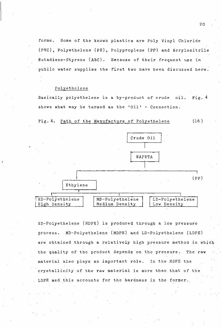
Polyethelene
Basically polyethelene is a by-product of crude oil. Fig. 4
shows what may be termed as the 'Oil1 - Connection.
Fig. 4. Path of the Manufacture of Polyethelene (16)
Crude Oil
NAPHTA
Ethylene
HD-Polyethelene High Density
T MD-Polyethelene Medium Density
(PP)
LD-Polyethelene Low Density
HD-Polyethelene (HDPE) is produced through a low pressure
process. MD-Polyethelene (MDPE) and LD-Polyethelene (LDPE)
are obtained through a relatively high pressure method in whic
the quality of the product depends on the pressure. The raw
material also plays an important role. In the HDPE the
crystallinity of the raw material is more than that of the
LDPE and this accounts for the hardness in the former.
21
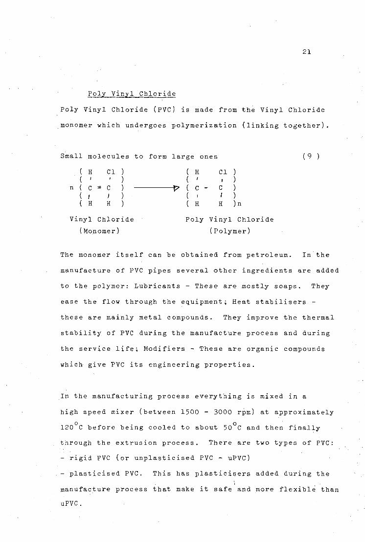
Poly Vinyl Chloride
Poly Vinyl Chloride (PVC) is made from the Vinyl Chloride
monomer which undergoes polymerization (linking together)
Small molecules to form large ones
CI
(9 )
( H ( '
n ( C = C ( / ; ( H H
Vinyl Chloride
(Monomer)
( H CI ( '
P ( C - C ( • '
( H H
Poly Vinyl Chloride
(Polymer)
The monomer itself can he obtained from petroleum. In the
manufacture of PVC pipes several other ingredients are added
to the polymer: Lubricants - These are mostly soaps. They
ease the flow through the equipment; Heat stabilisers -
these are mainly metal compounds. They improve the thermal
stability of PVC during the manufacture process and during
the service life; Modifiers - These are organic compounds
which give PVC its engineering properties.
In the manufacturing process everything is mixed in a
high speed mixer (between 1500 - 3000 rpm) at approximately
o . o
120 C before being cooled to about 50 C and then finally
through the extrusion process. There are two types of PVC:
- rigid PVC (or unplasticised PVC - uPVC)
- plasticised PVC. This has plasticisers added during the
manufacture process that make it safe and more flexible than
uPVC.
\
22
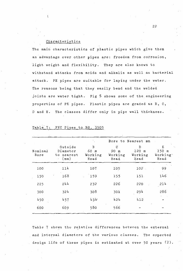
Charact eristics
The main characteristics of plastic pipes which give them
an advantage over other pipes are: freedom from corrosion,
light weight and flexibility. They are also known to
withstand attacks from acids and alkalis as well as bacterial
attack. PE pipes are suitable for laying under the water.
The reasons being that they easily bend and the welded
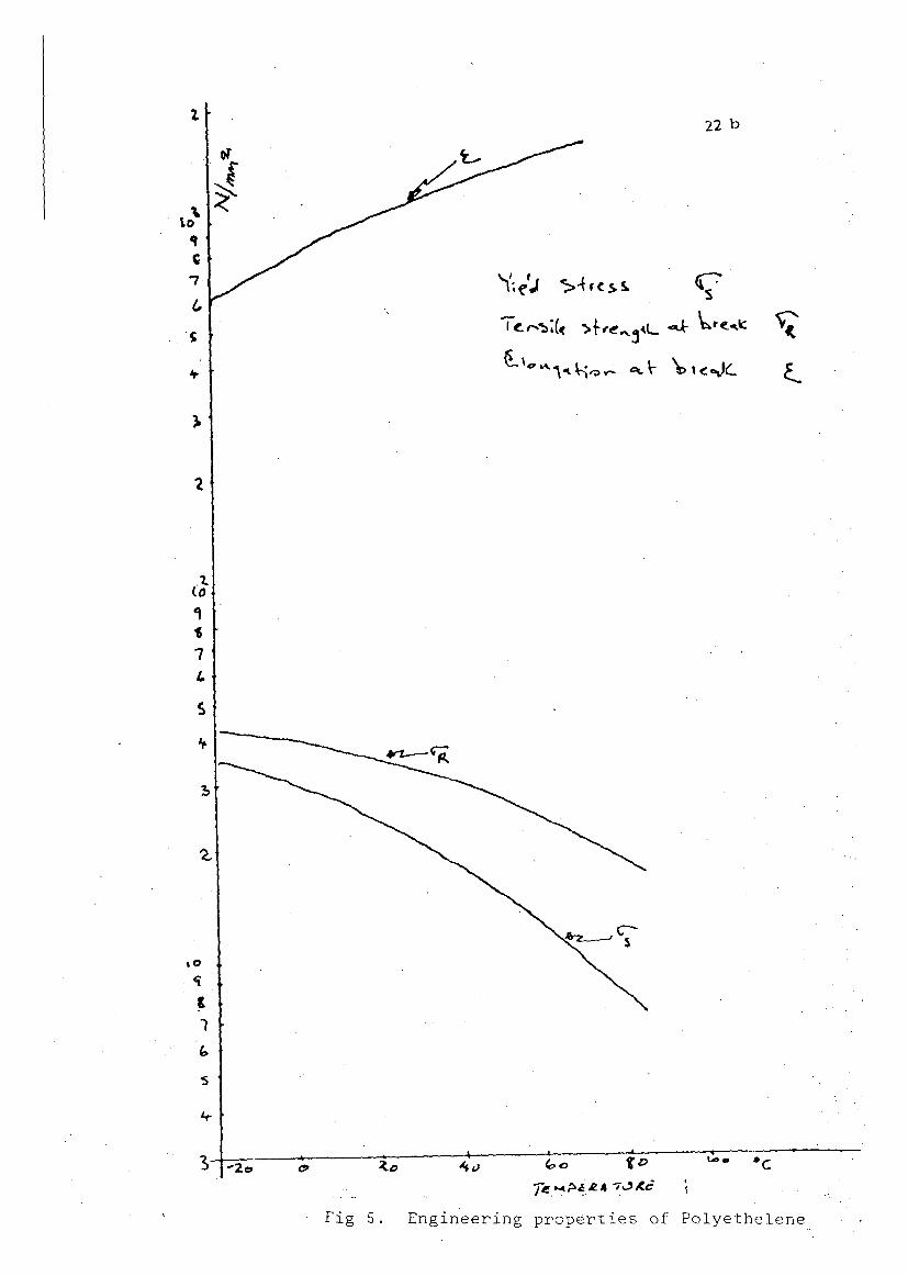
joints are water tight. Fig 5 shows some of the engineering
properties of PE pipes. Plastic pipes are graded as B, C,
D and E. The classes differ only in pipe wall thickness.
Table 7: PVC Pipes to BS. 3505
Nominal Bore
100
150
225
300
1+50
600
Out side Diameter
to nearest (mm)
Ilk
168
21+1+
32U
U5T
609
B 60 m
Working Head
107
159
232
308
U3U'
580
Bore to
C 90 m
Working Head
105
155
226
301
1+21+
566
Nearest mm
D 120 m
Working Head
102
151
220
29I+
1+12
-
E 150 m
Working Head
99
11+6
2ll+
286
-
-
Table 7 shows the relative differences between the external
and internal diameters of the various classes. The expected
design life of these pipes is estimated at over 50 years (2).
22 b
<T
rJ)
Co e »-Go f ©
Fig 5. Engineering properties of Polyethelene
23
Impact strength decreases with lowering temperature while
tensile strength decreases with increasing temperature and
these facts should he borne in mind when using these pipes
under extreme temperatures. Fig.U shows a graphical
representation of these characteristics. PVC tends to
embrittle when exposed to direct sunlight while Polyethelene
is affected by ultra violet rays.
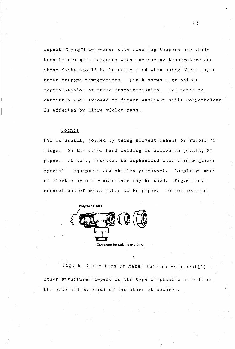
Joints
PVC is usually joined by using solvent cement or rubber '0'
rings. On the other hand welding is common in joining PE
pipes. It must, however, be emphasized that this requires
special equipment and skilled personnel. Couplings made
of plastic or other materials may be used. Fig.6 shows
connections of metal tubes to PE pipes. Connections to
Polythene pipe
Connector for polythene piping.
Fig. 6. Connection of metal tube to PE pipes (10.) .
other structures depend on the type of plastic as well as
the size and material of the other structures.
2k
3.2 Pre-Stressed Concrete
Manufacture
Pre-stressed pipes are made by tensioning 'high' tensile
wire around a cylindrical core. The core may consist of
either longitudinally prestressed concrete or a thin steel
cylinder which has a thin spun concrete lining to the
interior. The latter are referred to as 'cylinder prestressed
concrete pipes' and the former 'non-cylinder'. After the
wires have been wound and stressed a thick coat of concrete
is pneumatically poured externally onto the pipe evenly as
it is rotated. The design procedure for this pipe consists
of the calculation for different amounts of prestressing
steel. For each one, the geometrical and material
characteristics of the pipe and the admissible working pressure
is obtained. It is then possible to draw the curve 'admissible
working pressure versus steel quantity' and finally from the
required working pressure to find the necessary steel
section.
Characteristics
By increasing the number of prestressing steel it is possible
to raise the pressure capability of the pipe. The main
advantage of prestressed concrete pipes is that they are
cheaper than steel for diameters of 300 mm and above. They
are also able to withstand certain corrosive conditions
that would attack iron and steel. However, it has to be
protected against stress corrosion of the prestressing
25
steel. Since corrosion failure of the steel requires the
existence of water in contact with the steel surface, the
best way to avoid stress corrosion is to avoid the contact
of water with the prestressing steel. This may be achieved
either by making a waterproof mortar coating of the pipe
or protect the steel with sythetic resins. Other
disadvantages include weight and the fact that it is
almost impossible to make connections after the pipe has
been laid because of the need to cut into the prestressing
wires .
Joints
Joints for prestressed pipes are usually the lock joint-
push-in type where the socket and spigot may be made of
steel or prestressed concrete collars. Also the Viking
Johnson coupling shown in Fig. 8 may be applied.
3.3 Asbestos Cement
Manufacture
Asbestos cement (A-C) pipes are made of cement and
asbestos fibres mixed into a slurry and then deposited layer
upon layer around a cylindrical mould-like structure. When
the required thickness is reached the pipe is steam or water
cured.
26
Characteristics
A-C pipes have the characteristic property of being
resistant to corrosive conditions that would otherwise
be disastrous to cast, iron or steel. They also possess
good water tightness. Hence, they are used in
transmission mains. Compared to, say, concrete pipes
they have relatively low wall thickness. They do not
tuberculate.
However, these pipes suffer from a number of disadvantages
The major one being that the pipes tend to be brittle
and therefore liable to be easily damaged under impact
loads.
Special parts are made from metal (see Fig. 7a)
especially at take-off points. It is for this reason
that when cast iron is used on joints the pipeline must
be protected with bitumen if used in aggressive soils.
In general A-C pipes should be bitumen coated if
magnesium sulphate in the soil is greater than 2000 mg/1,
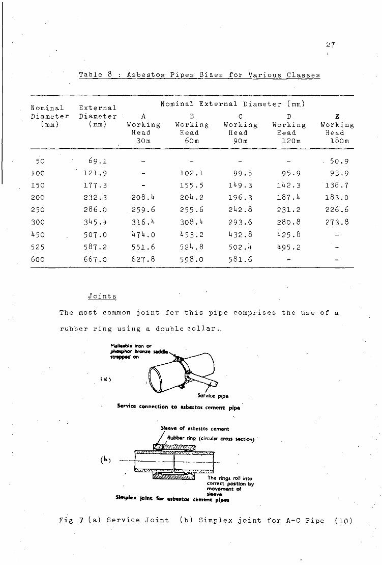
Table 8 showes the relative difference in internal and
external diameters for different classes of pipes.
27
Table 8 : Asbestos Pipes Sizes for Various Classei
Nominal Diameter
(mm)
50
100
150
200
250
300
1+50
525
600
External Diameter
(mm)
,
69.I
121.9
177.3
232.3
286.0
3h<>.k
507.0
587.2
667.O
A Working Head 30m
-
-
-
208.U
259.6
316.1+
U7U. 0
551.6
627.8
Nominal Ext
B Working Head 60m
-
102 .1
155.5
20l+ .2
255.6
308.1+
1+53.2
521+.8
598.0
ernal Diame
C Working Head 90m
-
99.5
1^9.3
196.3
21+2.8
293.6
1+32.8
502.1+
581.6
ter (mm)
D Working Head 120m
-
95-9
11+2.3
187.1*
231.2
280.8
1+25.8
1+95.2
-
E Working Head 180m
50.9
93.9
138.7
183.0
226.6
273.8
-
-
-
Joints
The most common joint for this pipe comprises the use of a
rubber ring using a double collar..
Malleable iron or phosphor bronte Mddte strapped on
IU)
Service pipe
Service connection to asbestos cement pipe
(t» •>.>.'/.•>•>>>.*».•>/>».
Sleeve of asbestos cement
Rubber ring (circular cross section)
\>.ti>>>»>,><Vi<>,: \
^Smmmf^4 ^The rings roll Into correct position by movernent of
«• 1 . sleeve Mnplex joint for asbestos cement pipes
Fig 7 (a) Service Joint (b) Simplex joint for A-C Pipe (10)
28
Common examples are the simplex joint (also known as the
'Fluid-Tite' joint) shown in Fig. 7b. The socket and
spigot joint, common in steel pipes, is not so common in
A-C pipes since most pipes are manufactured with plain ends.
3.4 Cast Iron
Manafacture
There are basically two types of cast iron pipes, vis., Grey
cast iron and spun iron. The latter is often called Ductile
iron. Basically both of them are composed of iron. The
difference comes in the manufacture, whereas grey iron pipes
are cast vertically in sand moulds. On the other hand
'spun iron' is prepared by pouring molten cast iron into a
horizontal water-cooled rotating mould. The centrigugal
forces flings the molten metal outwardly and evenly. The
metal solidifys after a few spins and is then drawn red.
After removing from the mould the pipe is again heated and
then cooled slowly to reduce stresses induced by chilling.
Characteristics
The spun iron pipes are of higher density and tougher than
the grey iron pipes. Both pipes have the disadvantage of
being heavy and liable to corrosion. Hence there is need
to coat them inside and outside. The practice is coal tar
pitching and sheathing with plastics. Grey iron is rather
rigid while spun iron is ductile. Consequently the American
Water Works Association has for Grey Iron AWWA HI standard
for rigid pipes structure and for Spun Iron AWWA HS
29
standard for which takes into account the ductility of
the material. Both types of pipes are suitable for large
diameter pipeline.
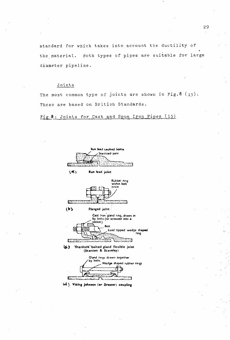
Joints
The most common type of joints are shown in Fig.8 (15).
These are based on British Standards.
Fig 8: Joints for Cast and Spun Iron Pipes (15)
Run lead caulked home • Sterilized yarn
v«> Run lead jo in t
Rubber ring within bolt circle
( t ^ Flanged joint
Cast Iron gland ring, drawn in by bolts (or screwed into a
^socket)
~*\ \~- aoit
lillilill V \ Load tipped wedge shaped •—r»^ r ing
•'J ''"'/M?>^,
I j t ) ' S t a n l o c k ' b o l t e d gland f lex ib le jo in t (S tan ton & Staveley)
Gland rings drawn together by bolts
Wedge shaped rubber rings
S i i a . : 1,' . i-,Vf"n E i 3 W . ) V ik ing Johnson (o r Dresser) coupl ing
30
(a) Run-end- j oint : Not so popular now "but still in use.
It requires high class workmanship. The lead which makes
I O . . .
t h e g r i p has t o be m i t a l l y h e a t e d t o 400 C. t h e j o i n t i s
r i g i d .
(h) Flanged joints: Special, care must be taken to ensure
alignment before inserting bolts to avoid fracture of the
pipe or frange. The rubber rig between the flanges must
lie inside the bolt circle and not intrude into the pipes.
Cleanliness must be observed.
(c) Compressed gasget joint: As can be seen from Fig.8 (c)
the principle is that of forcing the load tipped rubber into
an annular space.
(d) Viking Johnson Coupling: Commonly used for steel pipe
coupling. The principle is simply another version of
compressing rubber rings into the annular space. Except
there is no socket or spigot.
3.5 Steel
Manufacture
Usually steel pipes in rising mains are of large sizes.
These are made from steel plates bent to circular form.
The edges of the plate are either lap welded or bult welded.
Smaller sizes (32 to U 5 0 mm) known as 'seamless' are made
from ingots of hot steel which are pierced and then rolled
into cylinders of required dimension.
31
Characteristics
There are no standards for steel pipes because there must
be a minimum thickness to prevent bending of shape for
buried pipes or collapse of pipe, under partial vacuum
conditions. There must also be a minimum paractical
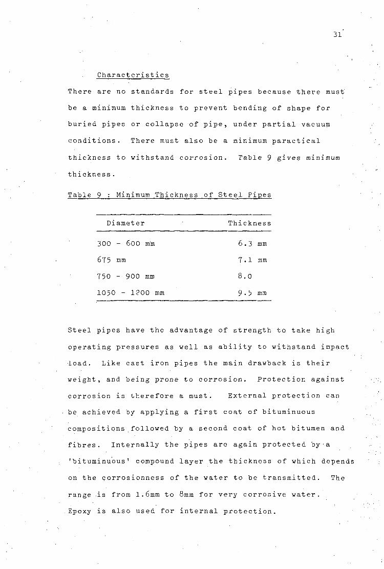
thickness to withstand corrosion. Table 9 gives minimum
thickness.
Table 9 : Minimum Thickness of Steel Pipes
Diameter Thickness
300 - 600 mm 6.3 mm
67 5 mm 7•1 mm
750 - 900 mm 8.0
1050 - 1200 mm 9•5 mm
Steel pipes have the advantage of strength to take high
operating pressures as well as ability to withstand impact
•load. Like cast iron pipes the main drawback is their
weight, and being prone to corrosion. Protection against
corrosion is therefore a must. External protection can
be achieved by applying a first coat of bituminuous
compositions followed by a second coat of hot bitumen and
fibres. Internally the pipes are again protected by•a
'bituminuous' compound layer the thickness of which depends
on the corrosionness of the water to be transmitted. The
range is from 1.6mm to 8mm for very corrosive water.
Epoxy is also used for internal protection.
32
According to tests performed on the Los Angeles rising
main after failures in 1971, conclusions were that steel
under low operating temperature has very little notch
toughness(9)#
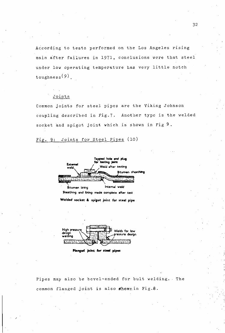
Joints
Common joints for steel pipes are the Viking Johnson
coupling described in Fig.7. Another type is the welded
socket and spigot joint which is shown in Fig 9.
Fig. 9: Joints for Steel Pipes (10)
Tapped hot* end plug for tasting joint
Bitumen lining Internal weld
Sheathing and lining made complete after test
Welded socket & spljot joint for steel pipe
Ranged joint for ttoai pipe*
Pipes may also he bevel-ended for bult welding. • The
common flanged joint is also tfhownin Fig.8.
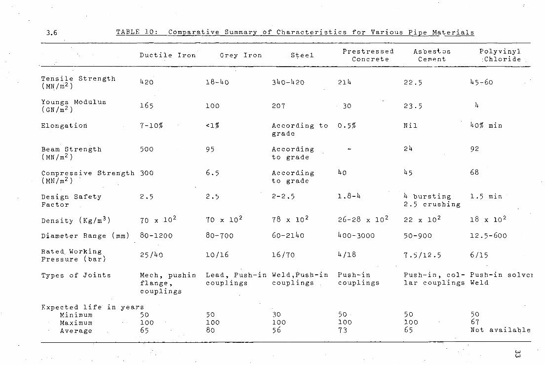
3.6 TABLE 10: Comparative Summary of Characteristics for Various Pipe Materials
Ductile Iron Grey Iron Steel Prestressed
Concrete Asbestos Cement
Polyvinyl Chloride
Tensile Strength (MN/m2) H20 18-Uo
Youngs Modulus (GN/m2)
Elongation
Beam Strength (MN/m2)
165
7-1056
500
100
<1%
95
Compressive Strength 300 (MN/m2)
Design Safety Factor
Density (Kg/m3)
Diameter Range (mm)
Rated. Working Pressure (bar)
Types of Joints
2.5
70 x 10'
80-1200
25/H0
6.5
2.5
70 x 10 2
80-700
10/16
3U0-U20
207
2lU
30
According to 0.5% grade
According to grade
According to grade
2-2.5
78 x 1 0 2
60-211+0
1 6 / 7 0
Uo
1.8-H
2 6 - 2 8 x 1 0 2
1+00-3000
U/18
Mech, pushin Lead, Push-in Weld,Push-in Push-in flange, couplings couplings couplings couplings
Expected life in years Minimum 50 Maximum • 100 Average 65
50 100 80
30 100 56
50 100 73
22.5
23.5
Nil
2U
h bursting 2.5 crushing
22 x 10 2
50-900
7.5/12.5
U5-60
k0% min
92
68
1.5 min
18 x 102
12.5-600
6/15
Push-in, col- Push-in solver lar couplings Weld
50 100 6 5 •
50 67 Not available
U) CO
34
3.7 Safety Factors Considerations
Although an attempt has been made in Table 10 to compare
safety factors of various materials this should not be
regarded as rigid. This is because different materials
have different failure modes, and their response to different,
external and internal forces are different. For example,
pressure rating for asbestos cement is calculated by
dividing quick burst pressure by a safety factory of, say,
U.0; While the pressure rating for cast iron pipes is
calculated by dividing the combination of maximum trench
load and quick burst pressure by a safety factor of 2.5.
It must be pointed out that in establishing these safety
factors it is assumed that the products response to short
term as well as long term pressure loads are not substantially
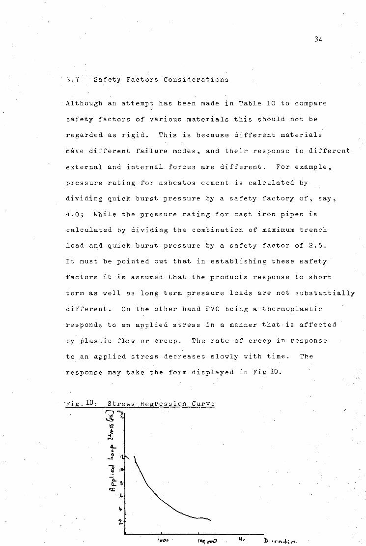
different. On the other hand PVC being a thermoplastic
responds to an applied stress in a manner that-is affected
by plastic flow or creep. The rate of creep in response
to an applied stress decreases slowly with time. The
response may take the form displayed in Fig 10.
Fig.10; Stress Regression Curve i—i "o
t?
a a 'K
<x A
Z
Itrpt l«»,«xrO H ' 'bi'ro4--|<-i
35
This means that the safety factor should be established
for long hours of stress application. Using, for example
100,000 hour stress application, the design stress upon
which pressure rating is based is then defined by dividing
the 'hoop' stress established on the stress regression curve
at 100,000 hour by a chosen safety factor.
3 .8 Standards
There are many standards for the manufacture and installation
of pipes adopted by individual countries. In Zambia mainly
British Standards are used. Extracts from these British
Standards for the pipes commonly used in Zambia have been
tabulated in Tables 11 to 15. Other International
Standards are:
IS0/R13 Cast iron pipes for pressure mains
IS0/R160 Asbestos-cement pressure pipes
ISO/R559 Steel pipes for gas, water and sewage
ISO/RII65 Plastic pipes for transport of fluids
ISO/R2531 Ductile iron pipes for pressure pipes
ISO/R2785 Guide to the selection of A-C pipes
subject to external loads.
It should be mentioned that there is a trend of change to
ISO Standards.
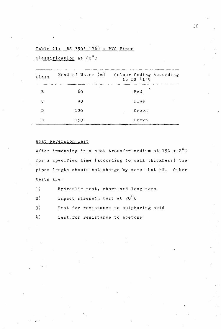
Table 11: BS 3505 1968 : PVC Pipes
Classification at 20 C
Class Head of Water (ra) Colour Coding According
to BS Ul59
B
C
D
E
6o
90
120
150
Red
Blue
Green
Brovn
Heat Reversion Test
After immensing in a heat transfer medium at 150 ±
for.a specified time (according to wall thickness)
pipes length should not change by more that 5%• 0t
tests are:
1) Hydraulic test, short and long term
2) Impact strength test at 20 C
3) Test for resistance to sulphuring acid
k) Test.for resistance to acetone
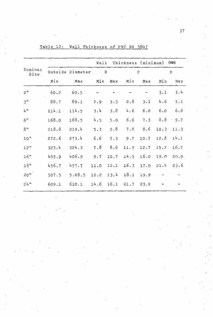
37
Table 12: Wall Thickness of PVC BS 3807
Wall Thickness (minimum) (nm)
Nominal Size
2"
3"
i t "
6"
8"
10"
12"
16"
18"
20"
2 It"
Outside Diameter B C D
Min Max Min Max Min Max Min Ma'x
60.2 60.5 - 3.1 3.h
88.7 89.I 2.9 3.3 2.8 3.1 It.6 5-1
llU.l • Hit.5 3.it 3.8 it.6 6.0 6.0 6.6
1 6 8 . 0 1 6 8 . 5 i t . 5 5 . 0 6 . 6 7 . 3 8 . 8 9 . 7
2 1 8 . 8 2 l 9 . i t 5 . 3 5 . 8 7 . 8 8 . 6 1 0 . 3 1 1 . 3
2 7 2 . 6 273.U 6.6 7 . 3 9 . 7 1 0 . 7 1 2 . 8 l i t . l
323 . i t 3 2 i t . 3 7 . 8 8 . 6 1 1 . 5 1 2 . 7 1 5 - 2 1 6 . 7
U05 .9 U 0 6 . 9 9 - 7 1 0 . 7 l i t . 5 1 6 . 0 1 9 . 0 2 0 . 9
U'56.7 i t 5 7 . 7 1 1 . 0 1 2 . 1 1 6 . 3 1 7 . 9 2.1. U 2 3 . 6
5 0 7 . 5 5 . 0 8 . 5 1 2 . 2 13 . i t 1 8 . 1 1 9 . 9
6 0 9 . 1 6 1 0 . 1 l i t . 6 1 6 . 1 2 1 . 7 2 3 . 9
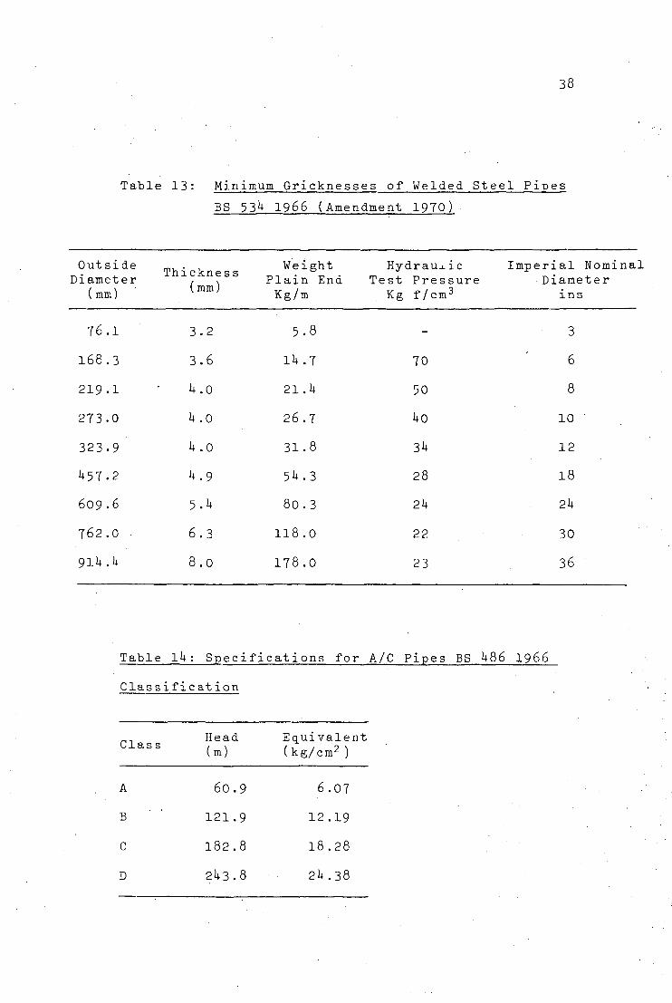
38
Table 13: Minimum Gricknesses of Welded Steel Pipes
BS 53k 1966 (Amendment 1970)
Outside Thicknes Weight Hydraulic Imperial Nominal Diameter , . Plain End Test Pressure Diameter
(mm) {mm) Kg/m Kg f/cm3 ins
76.1
168.3
219.1
273.0
323.9
U57.2
609 .6
762.0
91*+ .k
3.2
3.6
U.o
U .0
u . o
U.9
5.U
6.3
8.0
5.8
Ik .7
21 .1*
26.7
31.8
5U.3
80.3
118.0
178.0
-
70
50
Ho
3i+
28
2k
22
23
3
6
8
10
12
18
2k
30
36
Table ik: Specifications for A/C Pipes BS ^86 1966
Classification
Head Equivalent Clas s / -, /, . o \
(m) (kg/cm^)
A 60.9 6.07
B ' 121.9 12.19
C 182.8 18.28
D 21+3.8 21+.38
39
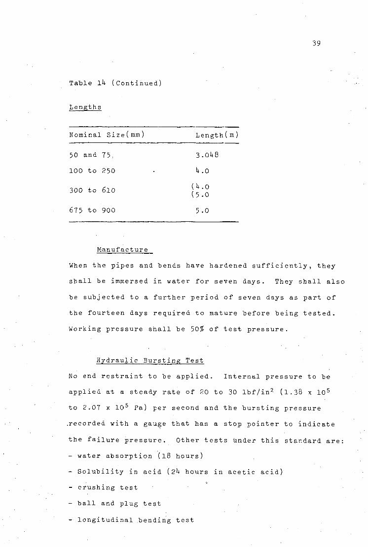
Table Ik (Continued)
Lengths
Nominal Size(mm)
50 and 75:
100 to 250
300 to 610
675 to 900
Length(m)
3.01+8
k.O
{k.O (5.0
5.0
Manufacture
When the pipes and bends have hardened sufficiently, they
shall be immersed in water for seven days. They shall also
be subjected to a further period of seven days as part of
the fourteen days required to mature before being tested.
Working pressure shall be 50% of test pressure.
Hydraulic Bursting; Test
No end restraint to be applied. Internal pressure to be
applied at a steady rate of 20 to 30 lbf/in2 (1.38 x 10 5
to 2.07 x 10 5 Pa) per second and the bursting p ressure
.recorded with a gauge that has a stop pointer to indicate
the failure pressure. Other tests under this standard are:
- water absorption (18 hours)
- Solubility in acid (2k hours in acetic acid)
- crushing test
- ball and plug test
- longitudinal bending test
1+0
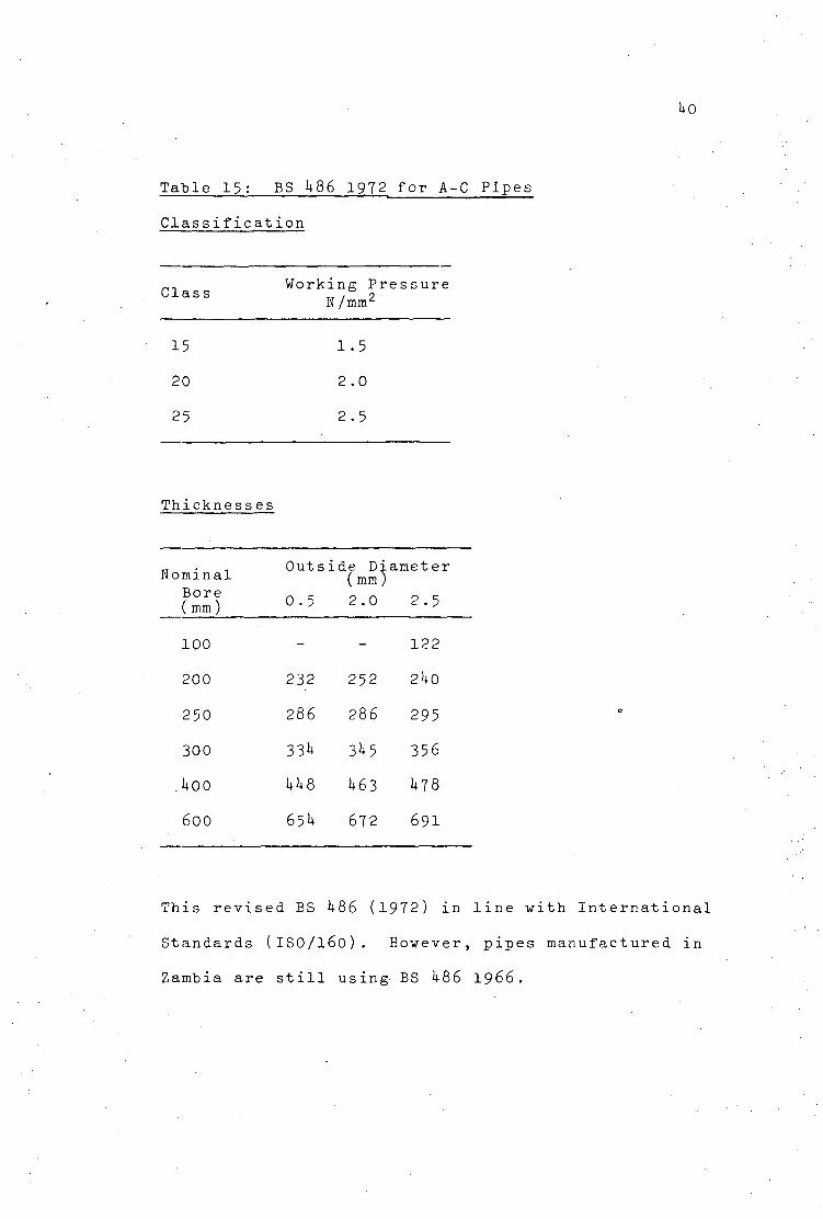
Table 1 5 : BS 1+86 1972, fo r A-C P i p e s
C l a s s i f i c a t i o n
Clas s Working Pressure
N/mm2
15
20
25
1.5
2.0
2.5
Thickness es
N o m i n a l B o r e ( mm)
1 0 0
2 0 0
2 5 0
3 0 0
.1+00
6 0 0
O u t s i
0 . 5
-
2 3 2
2 8 6
33*+
1+1+8
65I+
d e Di* (mm)
2 . 0
-
2 5 2
2 8 6
31+5
1+63
6 7 2
i m e t e r
2 . 5
1 2 2
2l+0
2 9 5
3 5 6
1+78
6 9 1
This revised BS 1+86 (1972) in line with International
Standards (ISO/160). However, pipes manufactured in
Zambia are still using BS 1+86 1966.
1*1
h. PIPE MATERIALS : THE ZAMBIAN EXPERIENCE
H.l Manufacture and Distribution
It can be generally said that three types of pipes (viz:
steel, asbestos cement, and PVC) are widely used in Zambia.
Cast iron pipes may be found in some old installations
especially in the mining areas. However, galvanized iron
pipes of small diameters have been using throughout the
country in the distribution networks. Originally all these
pipes were imported. However, industrial development within
the last fifteen years or so has made it possible to
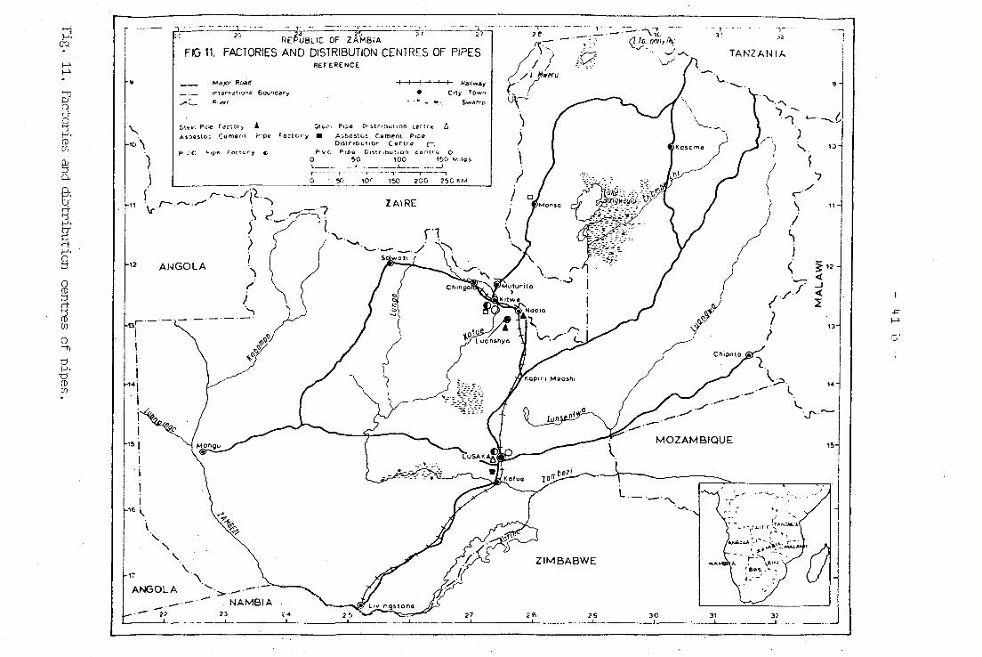
manufacture the three types locally. Fig.11 shows the
distribution of factories and distribution centres in the
country.
h .1.1 P.V.C.
PVC pipes are manufactured by a company called PLASTICO
in Lusaka. PROPORITE of Kitwe acts as the distribution
agent on the Copperbelt. The manufacture process used at
the Lusaka factory is the extrusion process mentioned-in
Chapter 3. Raw materials are ordered from Germany, United
Kingdom and Italy. The company has had some success in
exporting their pipes to neighbouring Malawi. The pipe
sizes are 6 m length and diameters range from 2 inches
(50 mm) to 6 inches (150 mm). They are using imperial
unit s .
REPUBLIC OF ZAMBIA
FIG 11. FACTORIES AND DISTRIBUTION CENTRES OF PIPES R E F E R E N C E
Major Road
3 ' Ji !
TANZANIA |
V... )
) V
,- > ^
<-S /
^d
1D-
11 -
< IH i
-P
1+2
1+ . 1.2 Asbestos Cement
Asbestos cement pipes are manufactured by TAP of Chilanga
a few kilometres south of Lusaka. The company has its own
distribution centre in Kitwe. The House of Mansa, although
not officially an agent of TAP, supplies users in Luapula
Province with A-C pipes. The manufacture process is the
same as mentioned in Chapter 3 using British Standards
BS 1+86. Only asbestos is imported, the cement is locally
produced. The products' size range from 50 mm to 600 mm.
U.1.3 Steel
Steel pipes are manufactured by two companies in Zambia,
viz: Hume (Zambia) Ltd. of Luanshya and Robert Hudson of
Ndola. Both companies apply arc welding using cold rolled
steel plates. However, the methods are slightly different
in the sense that Robert Hudson make spiral folding of the
steel plates while welding inside and outside. On the
other hand Hume only makes one fold and weld only outside
in a straight line. In both cases pipes are subjected to
hydraulic pressure tests and in some cases the pipes are
X-Ray tested in Kalulushi. Pipes are manufactured according
to British Standards BS 531+ and BS 3601. Raw materials are
ordered from West Germany, Japan and Swaziland. For pipe
protection various forms are used depending on the
requirements of the customer. Most of the manufactured
pipes are protected with spun bitumen with fibre glass
wrap and coal tar expoxy.
U3
It should be mentioned here that Hume (Zambia) Ltd. also
manufacture concrete pipes. However, the bulk of their
products are meant for low pressure applications.
Reinforced concrete pipes may be manufactured on request.
Pipe range from 150 mm to 91-4 mm.
U.2 Users' Experiences
h.2.1 Users' distribution
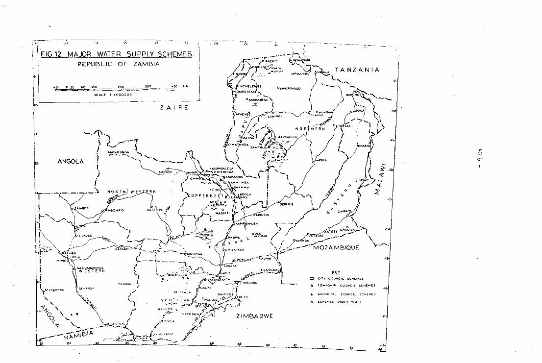
As indicated in Section U.l, three pipe materials are
mainly used in the rising main of most schemes in Zambia.
The users are evenly distributed throughout the Republic.
Fig.12 shows the main water supply schemes in Zambia.
This does not include village schemes, some of which
(e.g. in Luapula Province) are quite big and private
schemes owned by religious institutions. As far as the-
distribution of the three materials is concerned, it has
followed the pattern of the development of the towns. The
selection for the particular type of material was sometimes
governed by the people who designed the schemes. For
example, Luanshya, Mansa and Mbala were designed by one
consultant who recommended PVC pipes from his home country.
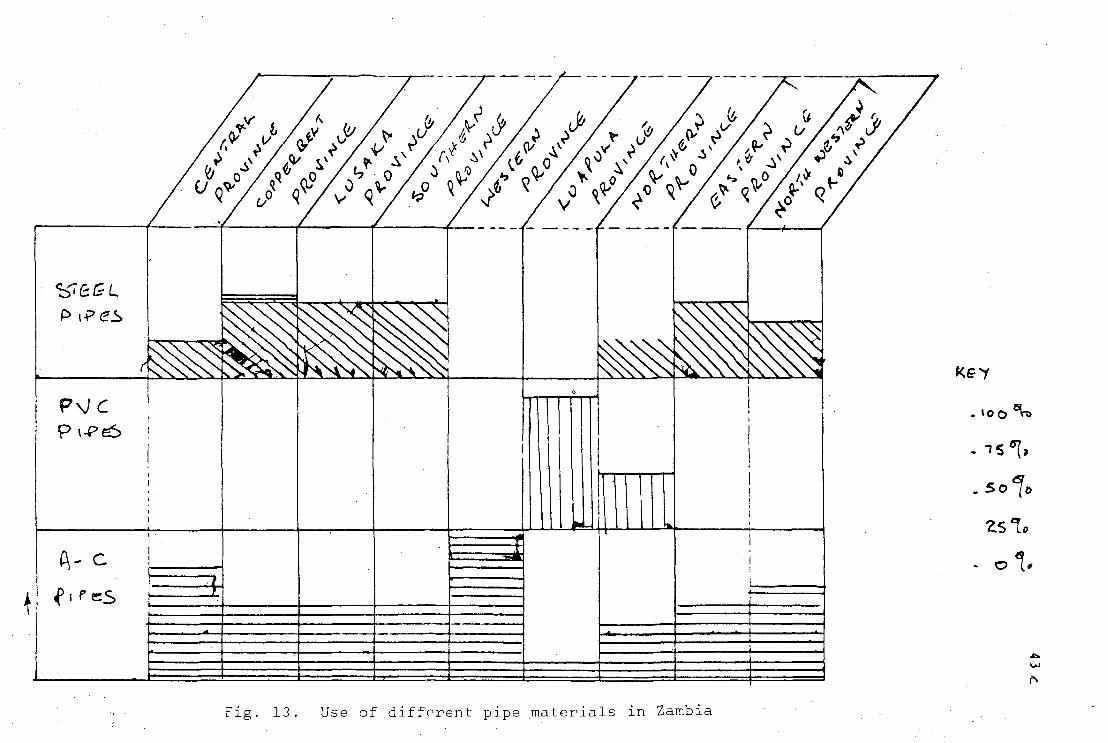
It can be said, however, that use of steel pipes has been
mainly restricted to areas of high population densities like
the major Copperbelt towns and cities. Fig. 13 showes the
distribution of the three pipe materials in the provinces.
This is by no means absolute but rather indicative. It is
also worth mentioning here that in most areas where PVC was
used it is slowly being replaced by steel pipes. Also
A- c
fifes
^
ZS*L
Fig. 13. Use of different pipe materials in Zambia
u
because of the decline in the use of PVC, the use of
asbestos cement pipes has been on the increase. The
replacement of PVC by steel pipes has been greatly
influenced by the local people.
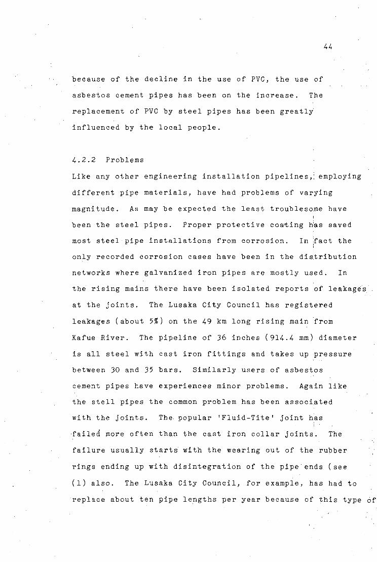
4. 2 .2 Problems
Like any other engineering installation pipelines,; employing
different pipe materials, have had problems of varying
magnitude. As may be expected the least troublesome have
been the steel pipes. Proper protective coating has saved
most steel pipe installations from corrosion. In Tact the
only recorded corrosion cases have been in the distribution
networks where galvanized iron pipes are mostly used. In
the rising mains there have been isolated reports of leakages
at the joints. The Lusaka City Council has registered
leakages (about 5%) on the 49 km long rising main from
Kafue River. The pipeline of 36 inches (914.4 mm) diameter
is all steel with cast iron fittings and takes up pressure
between 30 and 35 bars. Similarly users of asbestos
cement pipes have experiences minor problems. Again like
the stell pipes the common problem has been associated
with the joints. The- popular 'Fluid-Tite' joint has
failed more often than the cast iron collar joints. The
failure usually starts with the wearing out of the rubber
rings ending up with disintegration of the pipe ends (see
(l) also. The Lusaka City Council, for example, has had to
replace about ten pipe lengths per year because of this type
h5
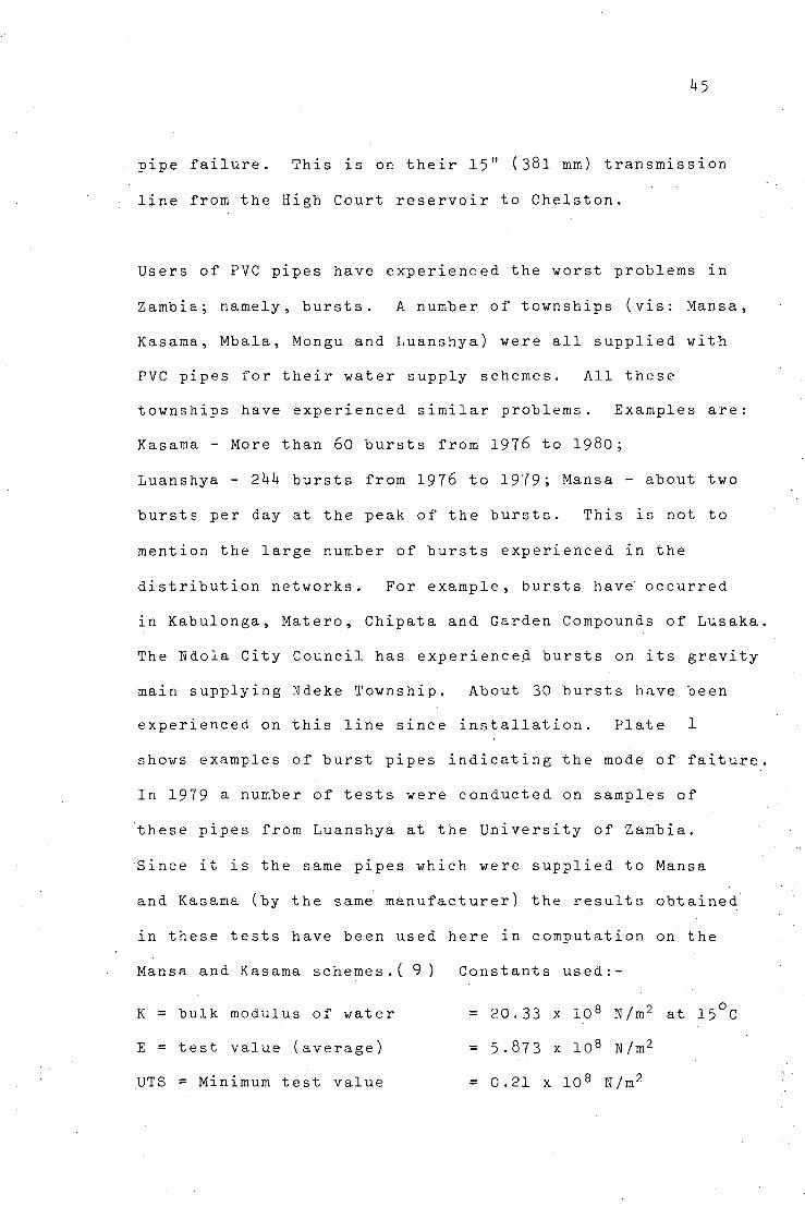
pipe failure. This is on their 15" (38l mm) transmission
line from the High Court reservoir to Chelston.
Users of PVC pipes have experienced the worst problems in
Zambia; namely, bursts. A number of townships (vis: Mansa,
Kasama, Mbala, Mongu and Luanshya) were all supplied with
PVC pipes for their water supply schemes. All these
townships have experienced similar problems. Examples are:
Kasama - More than 60 bursts from 1976 to 1980 ;
Luanshya - 2hh bursts from 1976 to 1979; Mansa - about two
bursts per day at the peak of the bursts. This is not to
mention the large number of bursts experienced in the
distribution networks. For example, bursts have occurred
in Kabulonga, Matero, Chipata and Garden Compounds of Lusaka,
The Ndola City Council has experienced bursts on its gravity
main supplying Ndeke Township. About 30 bursts have been
experienced on this line since installation. Plate 1
shows examples of burst pipes indicating the mode of faiture.
In 1979 a number of tests were conducted on samples of
these pipes from Luanshya at the University of Zambia.
Since it is the same pipes which were supplied to Mansa
and Kasama (by the same manufacturer) the results obtained
in these tests have been used here in computation on the
Mansa and Kasama schemes.( 9 ) Constants used:-
K = bulk modulus of water = 20.33 x 10 8 N/m2 at 15°C
E = test value (average) = 5-873 x 10 8 N/m2
UTS = Minimum test value = 0.21 x 10 8 N/m2
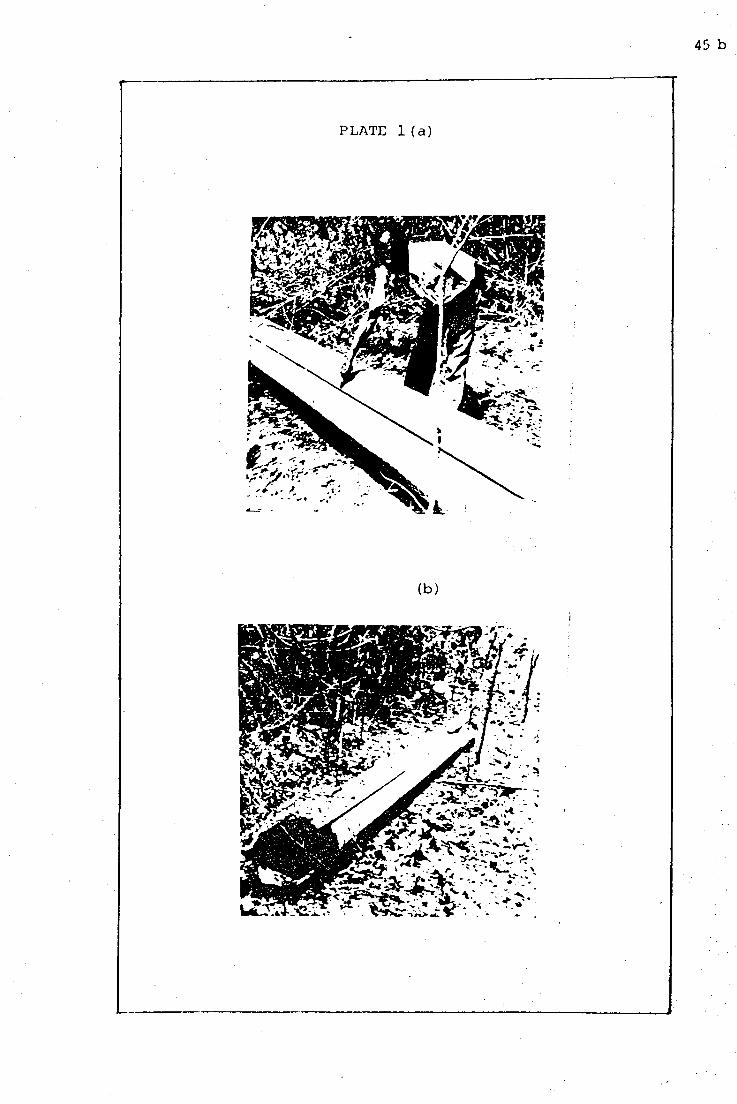
45 b
PLATE 1 ( a )
(b)
U6
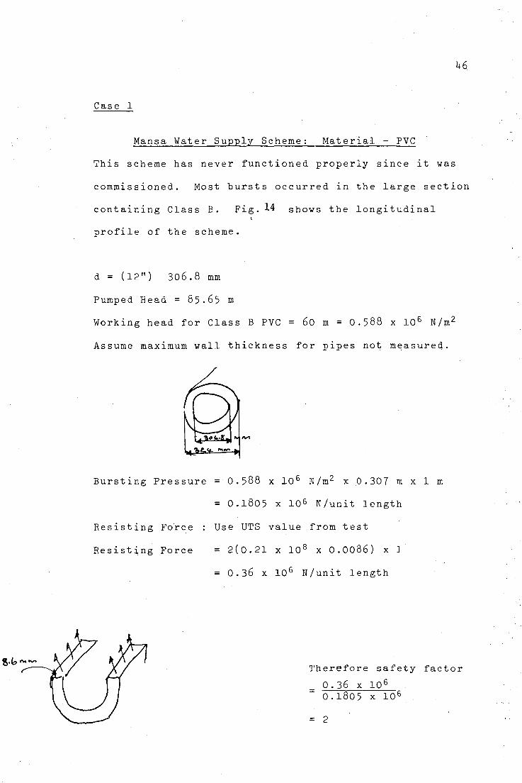
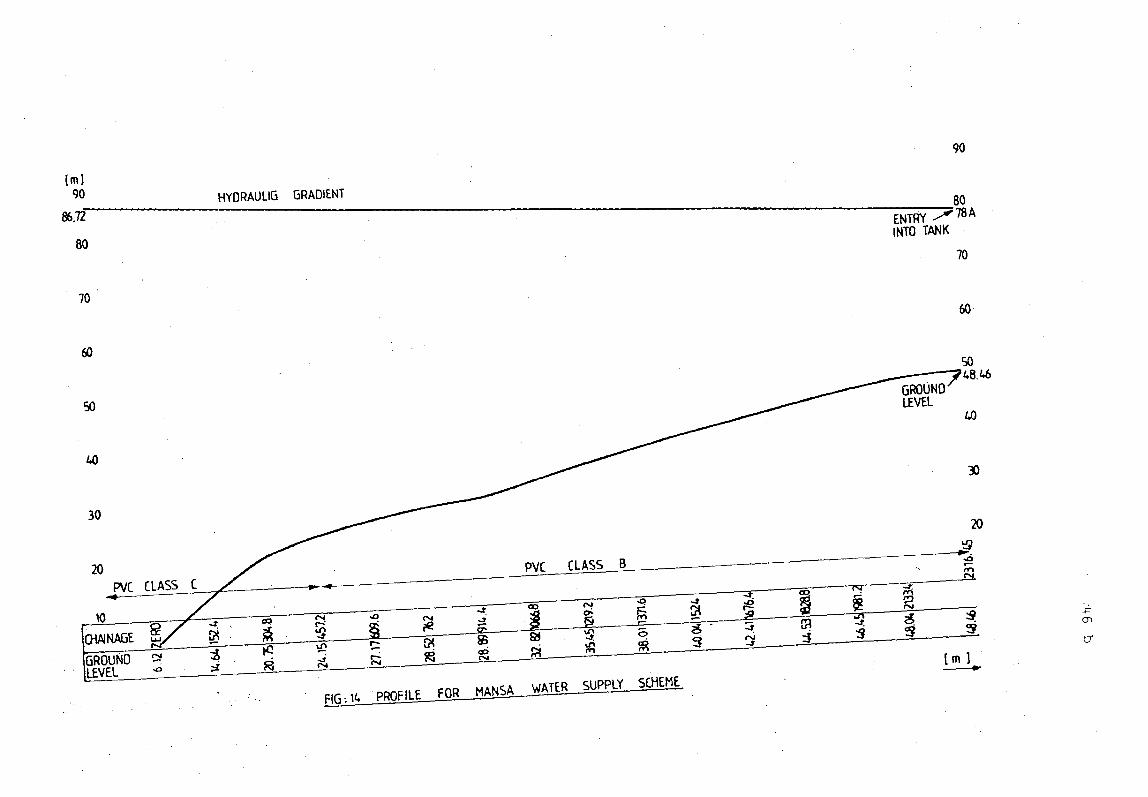
Case 1
Mansa Water Supply Scheme: Material - PVC
This scheme has never functioned properly since it was
commissioned. Most bursts occurred in the large section
containing Class B. Fig. 14 shows the longitudinal
profile of the scheme.
d = (12") 306.8 mm
Pumped Head = 85.65 m
Working head for Class B PVC = 60 m = O.588 x 106 N/m2
Assume maximum wall thickness for pipes not measured.
Bursting Pressure = 0.588 x 10 6 N/m2 x .0.307 m x 1 m
= 0.1805 x 10⁶ N/unit length
Resisting Force : Use UTS value from test
Resisting Force = 2(0.21 x 10 8 x 0.0086) x 1
= 0.36 x 10⁶ N/unit length
Therefore safety factor
0 . 3 6 x 1 0 6
0 . 1 8 0 5 x 1 0 6
= 2 xf
90
[ml 90 HYORAULIG GRADIENT 80
78 A 86.72 ENTRY INTO TANK
70
70 60
60
50
0)
30
20
10 CHA1NAGE
GROUND cs lEVEL__f.
PVC CLASS C
CD
V
^7
This safety factor is reasonable and one would have
expected the pipeline not to experience as many huruts
as it did. Unfortunately the pipeline was NOT Pressure
Tested before use. It is also clear from available
information that the pipes were subjected to pressures
higher than the recommended working pressure.
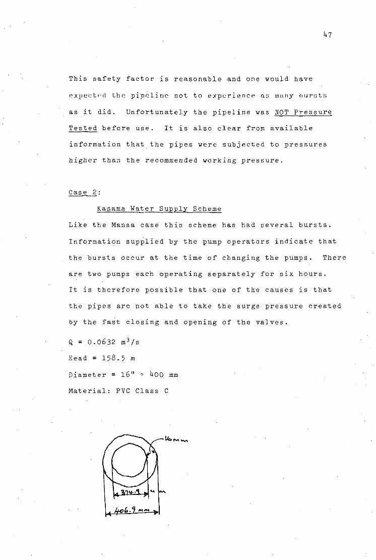
Case 2:
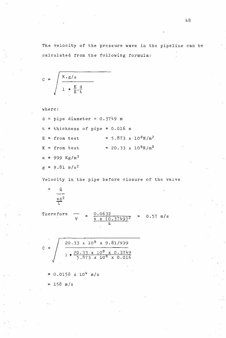
Kasama Water Supply_ Scheme
Like the Mansa case this scheme has had several bursts.
Information supplied by the pump operators indicate that
the bursts occur at the time of changing the pumps. There
are two pumps each operating separately for six hours.
It is therefore possible that one of the causes is that
the pipes are not able to take the surge pressure created
by the fast closing and opening of the valves.
Q = 0.0632 m3/s
Head = 158.5 m
Diameter = l6" - UOO mm
Material: PVC Class C
r<* xv^
L L^L.^ M~ y\
1+8
The velocity of the pressure wave in the pipeline can "be
calculated from the following formula:
C = K .g/a
1 + K cL E't
where:
d = pipe diameter = 0.37^9 m
t = thickness of pipe = 0.016 m
E = from test = 5-873 x 108N/m2
K = from test = 20.33 x 10⁸N/m2
a = 999 Kg/m3
g = 9.81 m/s2
Velocity in the pipe before closure of the valve
Q
ird< 1+
Therefore V
0.0632 TT x (0.37^9)^
k
0.57 m/s
C = 20.33 x 108 x 9-81/999
1 + 20.33 x 108 x 0.37l»9 5 .873 x 108 x 0.016
= 0.0158 x 10⁴ m/s
= 158 m/s
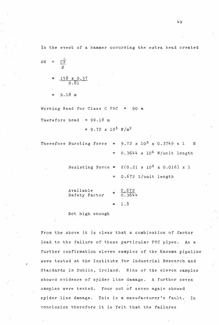
^9
In the event of a hammer occurring the extra head created
AH = CV
g
= 158 x 0.57 9.81
= 9.18 m
Working Head for Class C PVC = 90 m
Therefore head = 99-18 m
= 9-72 x 10 5 N/m2
Therefore Bursting Force = 9-72 x 10 5 x 0.371+9 x 1 N
= 0.36hk x 106 N/unit length
Resisting Force = 2(0.21 x 108 x 0.016) x 1
= 0.672 N/unit length
Available Safety Factor
Not high enough
0 .672
0.361+4
1.8
From the above it is clear that a combination of factor
lead to the failure of these particular PVC pipes. As a
further confirmation eleven samples of the Kasama pipeline
were tested at the Institute for Industrial Research and
Standards in Dublin, Ireland. Nine of the eleven samples
showed evidence of spider line damage. A further seven
samples were tested. Four out of seven again showed
spider line damage. This is a manufacturer's fault. In
conclusion therefore it is felt that the failures
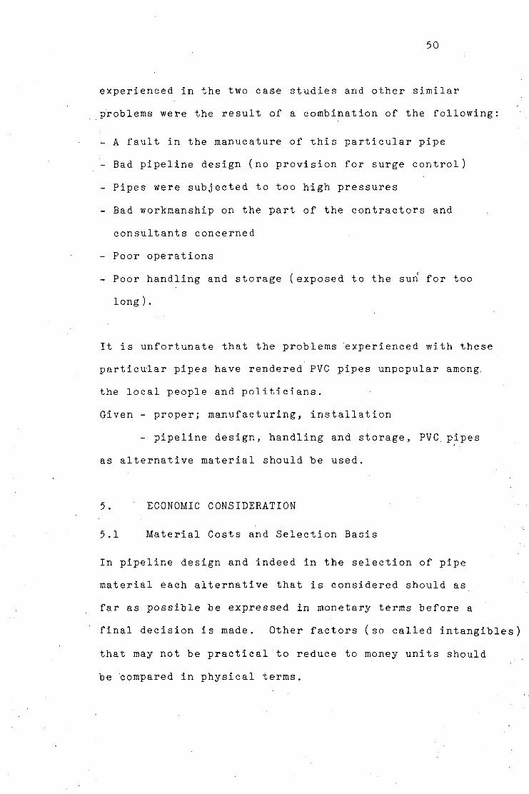
50
experienced in the two case studies and other similar
problems were the result of a combination of the following:
- A fault in the manucature of this particular pipe
- Bad pipeline design (no provision for surge control)
- Pipes were subjected to too high pressures
- Bad workmanship on the part of the contractors and
consultants concerned
- Poor operations
- Poor handling and storage (exposed to the sun for too
long).
It is unfortunate that the problems experienced with these
particular pipes have rendered PVC pipes unpopular among,
the local people and politicians.
Given - proper; manufacturing, installation
- pipeline design, handling and storage, PVC. pipes
as alternative material should be used.
5. ECONOMIC CONSIDERATION
5.1 Material Costs and Selection Basis
In pipeline design and indeed in the selection of pipe
material each alternative that is considered should as
far as possible be expressed in monetary terms before a
final decision is made. Other factors (so called intangibles)
that may not be practical to reduce to money units should
be compared in physical terms.
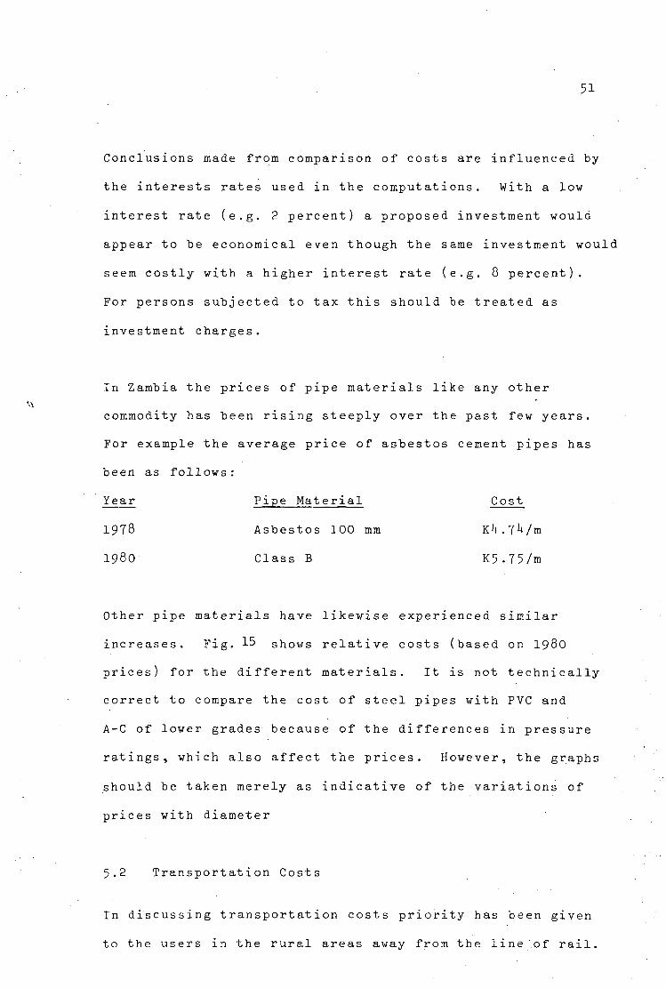
51
Conclusions made from comparison of costs are influenced by
the interests rates used in the computations. With a low
interest rate (e.g. 2 percent) a proposed investment would
appear to be economical even though the same investment would
seem costly with a higher interest rate (e.g. 8 percent).
For persons subjected to tax this should be treated as
investment charges.
In Zambia the prices of pipe materials like any other
commodity has been rising steeply over the past few ye
For example the average price of asbestos cement pipes
been as follows:
Year Pipe Material Cost
1978 Asbestos 100 mm K^.T^/m
1980 Class B K5.T5/m
Other pipe materials have likewise experienced similar
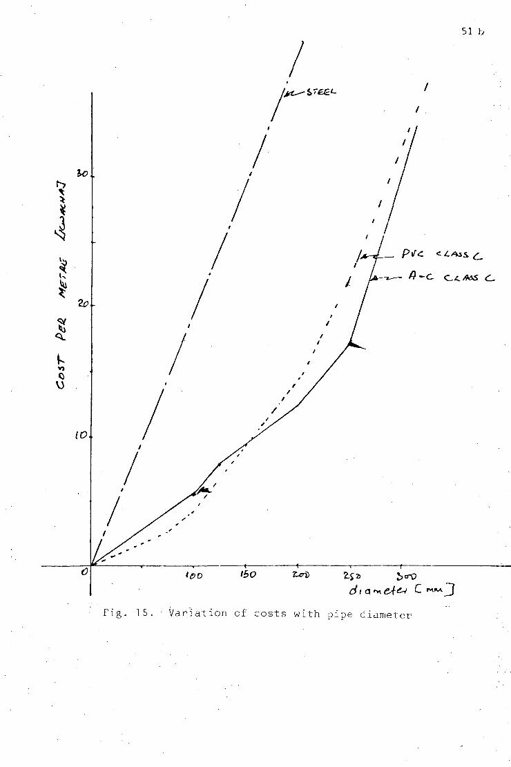
increases. Fig. 15 shows relative costs (based on 1980
prices) for the different materials. It is not technically
correct to compare the cost of steel pipes with PVC and
A-C of lower grades because of the differences in pressure
ratings, which also affect the prices. However, the graphs
should be taken merely as indicative of the variations of
prices with diameter
5.2 Transportation Costs
In discussing transportation costs priority has been given
to the users in the rural areas away from the line of rail.
51 b
Fig. 15. Variation of costs with pipe diameter
52
This is because of the Government's emphasis on rural
development and the fact that sometimes manufacturers
(e.g. Hume (Zambia) Limited) deliver pipes to the customers
on the Copperbelt and Lusaka without extra charge. The
word 'sometimes' must be emphasized because it depends on
the relationship between the manufacturer and the customer.
The quantity of pipes also matters. The usual practice is
for the customer to find his own transport. When the
manufacturer makes delivery he charges between 20 ngwee and
30 ngwee per kilometre. And again this is applicable only
on the Copperbelt and Lusaka. Private and semi-government
transporters have two systems of charging, viz:
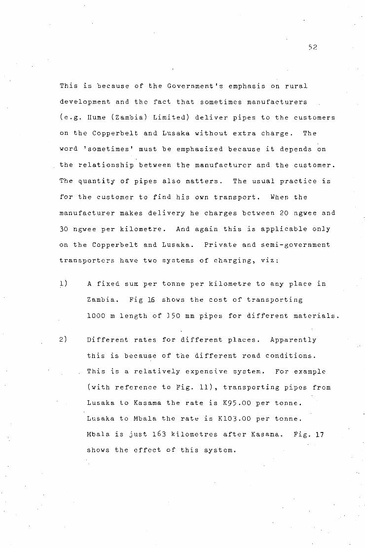
1) A fixed sum per tonne per kilometre to any place in
Zambia. Fig 16 shows the cost of transporting
1000 m length of 150 mm pipes for different materials.
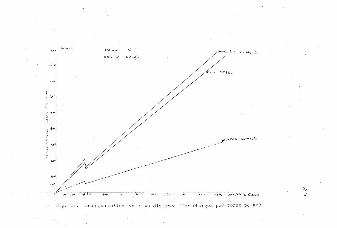
2) Different rates for different places. Apparently
this is because of the different road conditions.
This is a relatively expensive system. For example
(with reference to Fig. 11), transporting pipes from
Lusaka to Kasama the rate is K95.00 per tonne.
Lusaka to Mbala the rate is K103.00 per tonne.
Mbala is just l63 kilometres after Kasama. Fig. 17
shows the effect of this system.
-4--C CL«S b.
EG I.
£^S»>JO. CU'^V-b
Fig. 16 Transportation costs vs distance (for charges per tonne pe km)
MCi»*r> X
tic <v» <v-i n>
S2
tk-tt
I««J
I)JX>
1 © « a
fioo
f.OO
Jf-O*
TJOO
o
rv\0> A/.A
C w f l ^ f l
*L4.S * ^ A
f
5>e/2.e-/s>jfc:
A~<
M & A A.A
C /V * A< 4
AC A S A-«vf/q
M o t^<a O
/ / J / A / f i S T ^ f c
Se£o2-NjJ(C:
1
sr^e*.
M b / H _ A
C f-f * **A
£_/»-S> A-A</1
M o *>£> O
£ X VJ l /oG,S7z>AJfc
^ e ^ r O o e
'
7vC
wacha]
:res (k
ror various cenl
10 • P
o o •
c o
—i -t->
1 5 +->
nspc
rH
Fig.
53
5.3 Installation Costs
Laying costs of pipes are not fixed. That is to say a
contractor cannot tell off-hand the cost of laying, say,
100 metres regardless of material type. Of course the
cost of laying steel pipes for example will be more than the
cost of laying PVC pipes. However, the actual cost will
be a function of:
Location
In Zambia work cf this type is mostly done manually.
Since the cost of labour in urban areas is more than in
rural areas it follows that the laying costs will be
influenced by the location. Even when machinery is to be
used, the cost of transporting machinery to whatever
location will have a bearing on the overall cost.
Total Cost of Scheme
If a contractor is employed merely to lay, say, 100 metres
of pipeline the overall cost of laying will be higher than if
he were employed to undertake other jobs connected to the
scheme like installation of pumps and tanks.
Competition
This is very important in tendering engineering works. The
more competitors there are the lower are the costs. This
can be clearly seen in big projects.
It is for the above reasons that' no fixed rates are
available for laying different types of pipes. Each scheme
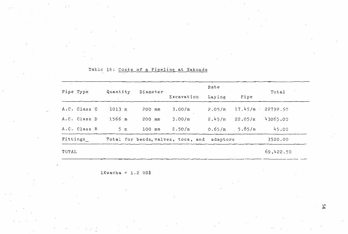
Table 16: Costs of a Pipeline at Nakonde
Rate Pipe Type Quantity Diameter Total
Excavation Laying Pipe
A.C. Class C 1013 m 200 mm 3.00/m 2.05/m 17.^5/m 22792-50
A.C. Class D 1566 m 200 mm 3.00/m 2.1+5/m 22.05/m ^3065.00
A.C. Class B 5 m 100 mm 2.50/m 0.65/m . 5.85/m ^5.00
Fittings
TOTAL
Total for bends, valves, toes , and adaptors 3520.00
69 ,U22 . 50
lKwacha = 1.2 US$
"I
)
^.OoOdi
/i>i«o°i
llc*v
.? L%oeO
V X^ooO
j ^ s7e£<-
^o»Oj
-....'£e>.otf.;rnrrr "'PC ^ " S r o 3<*? • r ^ 5c O t.<-e> 7 C " 8 » f Tff'.-
. P>J (_
4 *
'ig. .18. Transportation plus material costs vs distance
55
is defferent from another. Table 16 gives an example of the
overall cost for a pipeline scheme in Northern Province.
The project was carried out in 1979 . The costs exclude
backfilling and trimming.
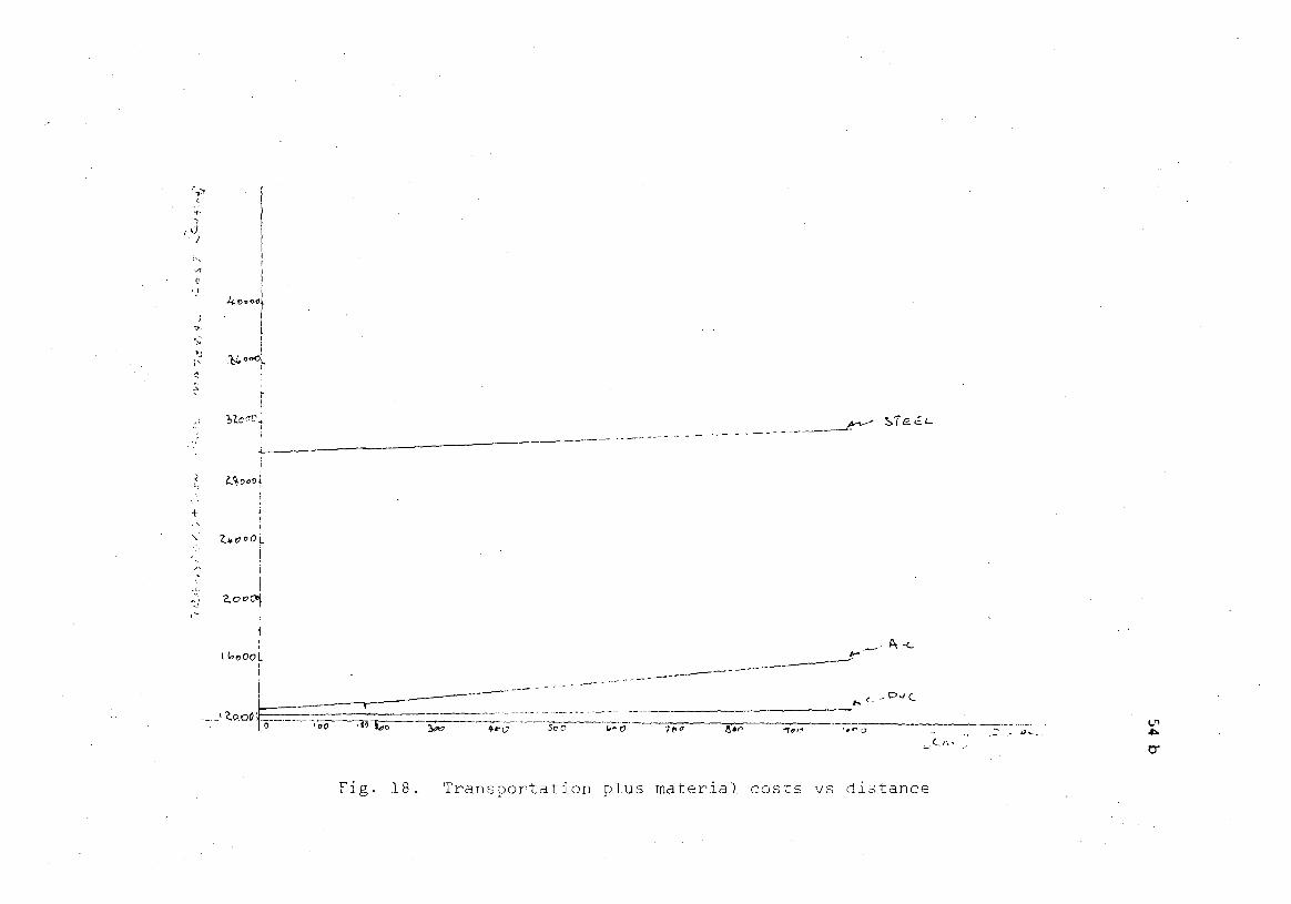
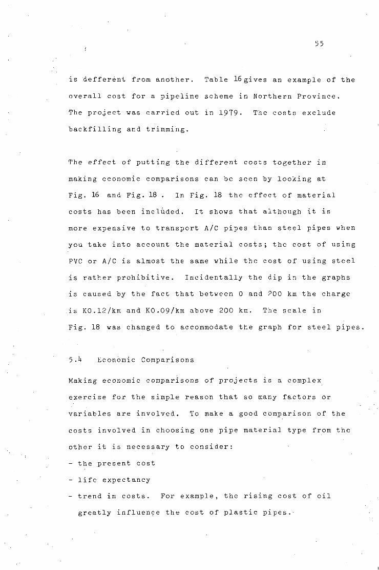
The effect of putting the different costs together in
making economic comparisons can be seen by looking at
Fig. 16 and Fig. 18 . In Fig. 18 the effect of material
costs has been included. It shows that although it is
more expensive to transport A/C pipes than steel pipes when
you take into account the material costs; the cost of using
PVC or A/C is almost the same while the cost of using steel
is rather prohibitive. Incidentally the dip in the graphs
is caused by the fact that between 0 and 200 km the charge
is K0.12/km and K0.09/km above 200 km. The scale in
Fig. 18 was changed to accommodate the graph for steel pipes.
5 A Economic Comparisons
Making economic comparisons of projects is a complex
exercise for the simple reason that so many factors or
variables are involved. To make a good comparison of the
costs involved in choosing one pipe material type from the
other it is necessary to consider:
- the present cost
- life expectancy
- trend in costs. For example, the rising cost of oil
greatly influence the cost of plastic pipes.'
56
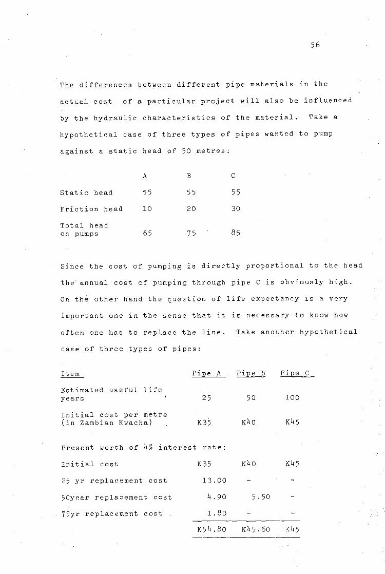
The differences between different pipe materials in the
actual cost of a particular project will also be influenced
by the hydraulic characteristics of the material. Take a
hypothetical case of three types of pipes wanted to pump
against a static head of 50 metres :
Static head
Friction head
Total head
A
55
10
B
55
20
C
55
30
on pumps 65 75 85
Since the cost of pumping is directly proportional to the head
the' annual cost of pumping through pipe C is obviously high.
On the other hand the question of life expectancy is a very
important one in the sense that it is necessary to know how
often one has to replace the line. Take another hypothetical
case of three types of pipes:
Item Pipe A Pipe B Pipe C
Estimated useful life years ' 25 50 100
Initial cost per metre (in Zambian Kwacha) . K35 K*i0 K\5
Present worth of k% interest rate:
Initial cost K35 K*+0 K*+5
25 yr replacement cost 13.00 -
50year replacement cost b.90 5-50
75yr replacement cost 1.80 -
K5i*.8o KI45.60 Ki+5
57
In the present social and political situations, it is worth
to note that decisions reached on the basis of economic
considerations may be over-ridden by--political or social
influences. For example, PVC pipes have become unpopular
in Northern and Luapula Provinces of Zambia for reasons
stated in Chapter Four. It is, however, hoped that the
analysis of the problem in this paper will help to change
the attitude of the public towards this pipe material.
6. GUIDELINES
Facts presented here are based on conclusions drawn from the
discussions in the previous chapters. It must'be emphasized
that what is stated here is not absolute but rather gives
a guide as to the use of different pipe materials in Zambia.
6.1 Material Selection
For a user at any place in rural Zambia pipe material
selection is influenced by:
- Hydraulic properties
- Costs
Other factors, for example, aggressive soils or corrosive
water, will be included in considering alternatives.
From Chapter Four it is clear that previous users of PVC
were careless. It is therefore felt that use of this type
of pipe in distant places should be encouraged. However,
58
usage should be limited to small scale schemes in terms
of consumption and static head. This is because experience
has shown that operators in 95% of cases have no proper
training. Consequently, pipeline systems are subjected to
pressures to which they were not designed for. In terms
of costs PVC for small scale schemes is fair. A scheme
serving up to a population of 10,000 falls in this category.
The deterioration of rubber rings in asbestos cement pipes
need further investigations to determine the real cause.
However, the cases studied showed that this failure caused
pipe replacement of about 0.1$ of installed length per year,
In terms of costs A-C has an upper hand over steel. A-C
pipes would therefore do well for medium size schemes.
Schemes serving between 10,000 and 30,000 people fall in
this category. For schemes designed to take very high
pressures steel pipes should be recommended. Also to be
included in this category are big schemes serving over
30,000 people.
6.2 Handling and Storage
The simple and geneal rule is handle and store all pipe
materials with care. However, the fact that A/C pipes may
break on sudden impact while plastic pipes may break or
deform calls for extra care in handling them.
59
Plastic Pipes
When handling plastic pipes it must be remembered that
the impact strength decreases with the fall in temperature;
the surface may easily get damaged when dragged on the
ground.
The above fact is also true when transporting these pipes.
When loading ensure that:
- Pipes are bound tight together
- The transporting bed is smooth
- No point loads on the pipes
During storage again ensure that:
- the bed is smooth
- the pipes are not stocked in piles of over three metres
- the pipes are not left in direct sunshine. Store in
cool place .
Asbestos-Cement Pipes
In a way most of what has been said for PVC pipes may also
be applied to A-C pipes in as far as handling and storage
are concerned. Differences occur on the fact that sunshine
or sun heat do not have the same adverse effect on A-C as
on PVC pipes. It should also be remembered to remove the
rubber rings (and store them in a cool place) that may be
inserted in advance if there is considerable time anticipated
between dispatch and installlation.
60
Steel Pipes
- Ensure that the protective coating is not damaged during
transportation and storage
- Avoid storing steel pipes in places of high humidity for
a long t ime.
6.3 Installation'
Installation practices vary from country to country and
may in fact vary from engineer to engineer depending upon
one's point of view. However, there are a number of general
factors that must he observed during installation:
- First and foremost is careful handling. It does not serve
any useful purpose to transport, and store a pipe carefully
only to damage it during installation. Pipes should NOT
be DROPPED into the trench, but should be literally laid.
Fig- 19 gives one example.
Dimentions of the trench are a function of the pipe
diameter and some times soil conditions. In general the
trench should not be deeper than 1.5m and trench width may
be pipe diameter plus 20cm on both sides at the bottom of
the trench. (14)
- Ensure that the ends are clean before joining.
- Minimize the time between the time, for excavating the trench
and backfilling.
- In some areas because of soil conditions or traffic it
may be necessary to support the trench.
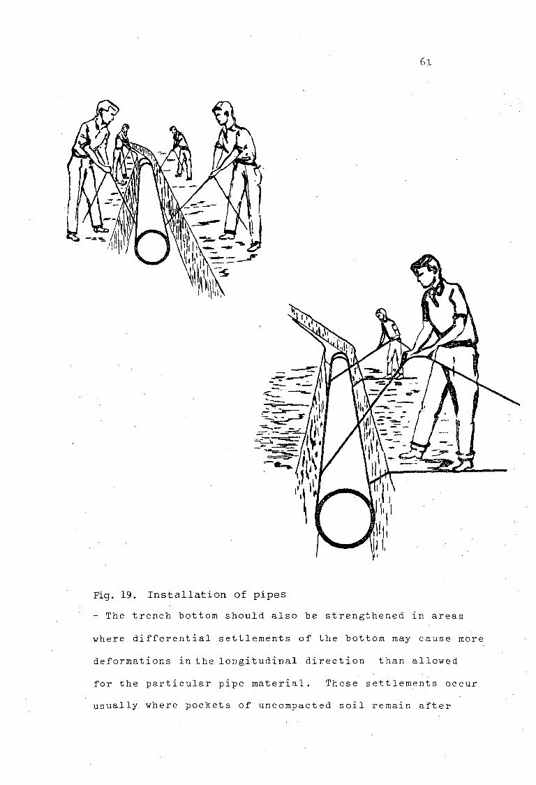
6.1
Fig. 19. Installation of pipes
- The trench bottom should also be strengthened in areas
where differential settlements of the bottom may cause more
deformations in the longitudinal direction than allowed
for the particular pipe material. These settlements occur
usually where pockets of uncompacted soil remain after
62
removing gravel or stones. When laying PE pipes under water
or for that matter any other pipe the bearing capacity of
( 14) '
the bottom must be determined.
- It may be necessary to add weight to the pipe to keep
it in position. But make sure the pipe is already filled
with water before laying and is air free.
- Care should be taken to protect the joints when laying
pipes. Fig.20 shows some methods of achieving this.
-In the Zambian conditions it is a must to allow for
expansion when making joints.
6.4 Remarks
The Ministry of Agriculture and Water Development should
prepare a manual for the selection and design for pipelines
suitable to Zambian conditions. This will help standardise
the work done. As it is now the different consultants,
contractors and even manufacturers apply British Standards
to suit their needs.
During the research period of this paper the writer was
unable to find old or new 'Cost Indices'. It is therefore
felt that'the Ministry of Works and Supply should publish
monthly or quarterly building and construction cost indices.
From this study it is clear that contractors and consultants
have taken advantage of the lack of technical knowledge by
the users in the rural areas. It is therefore felt that
a design manual should be accompanied with a proper inspection
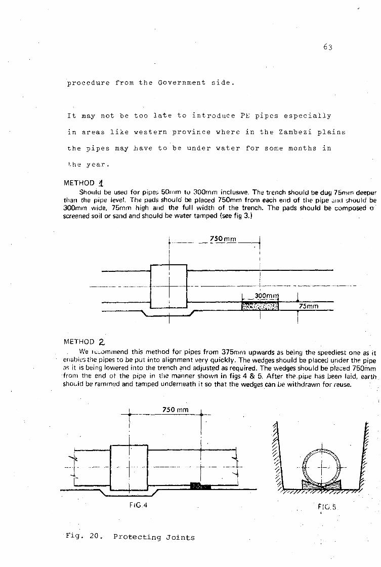
63
procedure from the Government side.
It may not be too late to introduce PE pipes especially
in areas like western province where in the Zambezi plains
the pipes may Jhave to be under water for some months in
the year.
METHOD 1 Should be used for pipes 50rnm to 300mm inclusive. The trench should be dug 75mrn deeper
than the pipe level. The pads should be placed 750mm from each end of the pipe ami should be 300mm wide, 75rnm high and the full width of the trench. The pads should be composed o screened soil or sand and should be water tamped (see fig 3.)
750 mm
^v J~
I 300rruTl EWJ~[.'-.'.U'.'.U| r ~ * * * • "
75 mm T
METHOD Z
We icommend this method for pipes from 375mrn upwards as being the speediest one as it enables the pipes to be put into alignment very quickly. The wedges should be placed under the pipe as it is being lowered into the trench and adjusted as required. The wedges should be placed 750mm from the end or the pipe in the manner showri in figs 4 & 5. After the pipe has been laid, earth should be rammed and tamped underneath it so that the wedges can be withdrawn for reuse.
750 mm
FIG.4 FIG.
Fig. 20. Protecting Jo in ts
6.4
REFERENCES
Associated Engineeering Services Limited,(1977),
Zambia Water Wastage Studies, Vol. 1.
Bromell, R.Y.: Design Criteria and Experiences in the
Use of Various Materials. (1977) International
Standing Committee on Water Distribution.
Committee on Pipeline
and Waste Water.
Civil Engineers.
Dake, J.M.K. (1972): Essentials of Engineering Hydraulic
pp 26-48
Fair, G.M., Geyer, J.C., Okum, D.H. (1966): Water and
Waste Water Engineering, Vol. 1, ppl2.0-12.30.
Gerald, F. Mouser, Clark, R.H. (1972): Loads on Buried
Pipes. Journal .Water and Sewage Works, Vol. 1
Kerr, S., Logan (1966): Effect of Valve Operation on
Water Hammer. Journal, American Water Works
Association, Vol. 52, No. 1.
Kristiansen, E. (1977): Degradation of Concret
Asbestos-Cement Pipes. Norwegian Institut
Water Research. Unpublished.
Marianayagam, C.C. (1980): Investigations into
of Locally Manufactured (and imported) PVC
for Water Supply. University of Zambia.
Mieges, J.W., Walker, S.J., Woodhull, R.C. (1980):
Asbestos-Cement Pipes no danger in Connecticut.
Journal Water and Sewage Works. June.
Planning, Pipeline Design for Water
(1975), American Society of
e and
e. for
the Use
pipes
65
Mikaoka, J. (1977): Pipelines laid in difficult
Conditions, including Earthquake Zone. International
Standing Committee on Water Distribution.
Philips, R.V., Roland, I.F., (1972): Pipeline Problems.
Journal, American Water Works Association,
pp 421-442.
Robert, J. Hucks (1972): Design of PVC Pipeline for
Water Distribution System. Journal American Water
Works Association. May 10.
Suomen Standardisoimisliitto, SF.S31H:E (1974)
pp 2-26.
Twort, A.C., Hoather, R.C., Law, F.M.,(1979): Water
Supply. Second Edition.
0Y Wiik & Hoglund, A.B., (1980): Sales Manual. VASA,
Finland.
TAMPEREEN TEKNILLINEN KORKEAKOULU I f f l i l m S i l N ^ ' VESlTEKNIIKKA I l i f f l i M l i l ' JULKAISUJA l i f f i H § f |'.' -:
;'
TAMPERE UNIVERSITY OF TECHNOLOGY ' S ^ H B K ^ ^ WATER SUPPLY AND SEWERAGE l ^ l ^ P ^ P r ! PUBLICATIONS
1. Luonsi, A., Jateveden blologinen puhdistus matallssa lampotiloissa. 1980. 138 s. (Summary fn English).
2. Salmela, K., Blologinen foforinpoisto PhoStrip-menetelmalta. 1979. 95 s.
3. Suominen, A., Puhtaan hapen kaytto aktllvilletemenetelmassa. 1979: 63 s.
4. Marstio, E., Jarven kunnostaminen vesisyvyytta llsaamaUi. 1979.134 s.
5. Salokangas, R., Katko, T., VSnnl, M., Wort-Cost Analysts In Water Supply — Case Study. 1980. 70 p.
6. Kayombo, W.R.C., Pipe Materials in Transmission Mains. 1981. 65 p.
7. Mashauri, D.M.A., Selection of Settling Basin for Sediment Removal. 1981. 143 p.
8. Mlengu, J.M.K., Operation and Maintenance Practice for Rural Water Supply in Kilimanjaro Region. 1981.112 p.
9. Msengi, R.M.C., Windmills within Water Supply. 1981. 83 p.
10. Njau, B.E., Hydrogeological Investigations in Water Master Plans of Tanzania. 1981.184 p.
11. Odira, P,M.A.A., Selection of Drifts or Bridges in Semidesert Areas of Flash Roods. 1981.102 p.
12. Riti, M.M., Horizontal Roughing Filter in Pretreatment of Slow Sand Filters. 1981.145 p.
13. Shawa, W.C., Manganese Removal in Kitwe Water Works. 1981. 47 p.
TAMPERE UNIVERSITY OF TECHNOLOGY Tieteenkatu 21, Hervanta
POSTAL ADDRESS: P.O. BOX 527 TEL.: 358 - (9)31 -162 111 SF-33101 Tampere 10 TELEX: 22-313 ttktr-sf
Related Documents


![[UPSC MAINS-2014] Insights Secure Mains, 01 August 2014 · [UPSC MAINS-2014] Insights Secure Mains, ... Critically evaluate the success of the South Asian Association for Regional](https://static.cupdf.com/doc/110x72/5ada2dfe7f8b9ae1768cd560/upsc-mains-2014-insights-secure-mains-01-august-upsc-mains-2014-insights-secure.jpg)


