-1- MODIFICATION OF CORE -SHAPE FOR IMPROVEMENT OF PRODUCTIVITY OF MALLEABLE IRON PIPE FITTINGS (SOCKET 1", 1 " ) THESIS Submitted in partial fulfilment for the award of the deg ree of MASTER OF TECHNOLOGY In PRODUCTION ENGINEERING Submitted By Krishan Dev 100628181031 PUNJAB TECHNICAL UNIVERSITY JALANDHAR

Welcome message from author
This document is posted to help you gain knowledge. Please leave a comment to let me know what you think about it! Share it to your friends and learn new things together.
Transcript

7/29/2019 Pipe Line Socket Thesis
http://slidepdf.com/reader/full/pipe-line-socket-thesis 1/81
-1-
MODIFICATION OF CORE -SHAPE FOR
IMPROVEMENT OF PRODUCTIVITY OF
MALLEABLE IRON PIPE FITTINGS
(SOCKET 1", 1
"
)
THESIS
Submitted in partial fulfilment for the award of the degree of
MASTER OF TECHNOLOGY
In
PRODUCTION ENGINEERING
Submitted By
Krishan Dev
100628181031
PUNJAB TECHNICAL UNIVERSITY
JALANDHAR
7/29/2019 Pipe Line Socket Thesis
http://slidepdf.com/reader/full/pipe-line-socket-thesis 2/81
-II-
MODIFICATION OF CORE -SHAPE FOR
IMPROVEMENT OF PRODUCTIVITY OF
MALLEABLE IRON PIPE FITTINGS
(SOCKET 1", 1
"
)
THESIS
Submitted in partial fulfilment for the award of the degree of
MASTER OF TECHNOLOGY
In
PRODUCTION ENGINEERING
Submitted By: Under Guidance of:
Krishan Dev Er. Gautam Kocher
Roll No. 100628181031 Asst. Prof.
Production Engg. Deptt.
R.I.E.T Phagwara, Punjab (INDIA)
Department of Mechanical Engineering
R AMGARHIA INSTITUTE OF ENGG. & TECHNOLOGY
PHAGWARA.
AFFILIATED TO PUNJAB TECHNICAL UNIVERSITY, JALANDHAR
7/29/2019 Pipe Line Socket Thesis
http://slidepdf.com/reader/full/pipe-line-socket-thesis 3/81
-III-
DECLARATION
I hereby certify that the thesis titled: Modification of Core-Shape for Improvement of
Productivity of Malleable Iron Pipe Fittings (Socket 1ʺ, 1 ʺ) in partial fulfilment for
the Award of Degree of Master of Technology in Production Engineering at
Ramgarhia Institute of Engineering & Technology, Phagwara is an authentic record of
my work carried out under the supervision of Er.Gautam Kocher, Assistant Professor,
Mechanical Engineering Department Ramgarhia Institute of Engineering & Technology,
Phagwara. I have not submitted the matter presented in the thesis anywhere for the award
of degree.
(Krishan Dev)Roll No. 100628181031
CERTIFICATE
This is to certify that the above statement made by the candidate is correct to the best of
my knowledge and belief.
Er.Gautam Kocher
Assistant Professor
The Viva-Voce examination of Krishan Dev (Roll No.100628181031) has been
conducted successfully on __________________
Supervisors HOD External
Examiner

7/29/2019 Pipe Line Socket Thesis
http://slidepdf.com/reader/full/pipe-line-socket-thesis 4/81
-IV-
ABSTRACT
The term pipe fittings include a number of fittings e.g. elbow, tee, socket, union etc.
These fittings should have chamfering at outlet. The chamfering is provided to assist
assembly and prevent damage to the start of thread. The chamfering should have an
included angle of 900
± 50. Presently there is practice of chamfering malleable iron pipe
fittings after these have been galvanized.
In this work, new shaped cores for malleable iron sockets 1ʺ, 1 ʺ have been
developed. With the use of these new cores, we get sockets after casting which don’t
need chamfering anymore. The occurrence of chamfering during casting process savesthe valuable time required for chamfering operation. The sockets casted by using these
new cores are lighter in weight than the existing sockets. Other dimensions of new
sockets are kept unchanged. Thus the number of sockets that can be made from the same
amount of molten metal has increased. Thus the scrap production due to chamfering
operation has reduced. The labour cost of chamfering has eliminated due to use of these
new cores. Thus the productivity has increased due to reduction in time of production,
scrap production and labour cost.
Keywords: Chamfering, Malleable, Core, Pipe Fittings.

7/29/2019 Pipe Line Socket Thesis
http://slidepdf.com/reader/full/pipe-line-socket-thesis 5/81
-V-
ACKNOWLEDGEMENT
I am heartily grateful to the supreme power almighty with whose blessings I have been
able to complete this study.
I owe my profound gratitude to my guide Er.Gautam Kocher Assistant Professor
Mechanical Engineering Department of Ramgarhia Institute of Engineering. &
Technology Phagwara for his inspiring and pains taking supervision, valuable guidance,
suggestions at every stage of my thesis. Without his critical review and valuable
discussions this work could not have been produced to its present form.
I would like to acknowledge the cooperation and help rendered by Er. R.K.Dhawan,
Principal and Er. Harvinder Lal Assistant Professor, Ramgarhia Institute of Engg. &
Technology.
I am also thankful to the proprietors of B.N. Industry, Jalandhar city for providing me
infrastructural facilities.
KRISHAN DEV
Roll No. 100628181031
7/29/2019 Pipe Line Socket Thesis
http://slidepdf.com/reader/full/pipe-line-socket-thesis 6/81
-VI-
TABLE OF CONTENTS
Topic Page
Declaration & Certificate III
Abstract IV
Acknowledgement V
Table of Contents VI-VII
List of Figures VIII-IX
List of Tables X
List of Publications XI
Chapter 1: Introduction 1-28
1.1 Process of manufacturing of G.I. Malleable Pipe fittings 2
1.2 Terminology 16
1.3 Types of Fittings 17
1.4 Core 19
1.5 Core Materials 20
1.6 Core Sands Which Require Heat Treatment 21
1.7 Core Sand Which Do Not Require Heat Treatment 23
1.8 Washes, Pastes, Powders and Other Dressings 24
1.9 Core Frames 27
1.10 Machine Core making 28

7/29/2019 Pipe Line Socket Thesis
http://slidepdf.com/reader/full/pipe-line-socket-thesis 7/81
-VII-
Chapter 2: Literature Review 29-35
Chapter 3: Problem Formulation 36
Chapter 4: Experimental Work 37-53
4.1 Experimental Introduction 37
4.2 Work Place 37
4.3 Procedure for making core box, Pattern of socket 37
4.4 Manual Core making 40
4.5 Procedure for making moulding sand, mould and casting of socket 43
4.6 Tools & Equipments Required 47
Chapter 5: Results 54-67
5.1 Analysis 61
5.2 Discussion 63
Chapter 6: Conclusion 68
6.1 Scope of Improvement 68
References 69-70

7/29/2019 Pipe Line Socket Thesis
http://slidepdf.com/reader/full/pipe-line-socket-thesis 8/81
-VIII-
LIST OF FIGURES
Figure No. Page
Figure 1.1 Pipe Fittings 1
Figure 1.2 Induction Furnace 3
Figure 1.3 Annealing Furnace 4
Figure 1.4 Equipment for Compression 5
Figure 1.5 Grinding Machine 6
Figure 1.6 Shot Blasting Machine 7
Figure 1.7 Dry Galvanizing Process 12
Figure 4.1 Core Box 37
Figure 4.2 Core Box 1ʺ (sectional view) 38
Figure 4.3 Core Box 1 ʺ (sectional view) 38
Figure 4.4 Pattern of Socket 39
Figure 4.5 New Cores 40
Figure 4.6 New Cores of Socket 1ʺ 41
Figure 4.7 Existing Core of Socket 1ʺ 41
Figure 4.8 Existing Core of Socket 1 ʺ 42
Figure 4.9 New Core of Socket 1 ʺ 42
Figure 4.10 Making of Moulds 44
Figure 4.11 New Pieces of Socket 45

7/29/2019 Pipe Line Socket Thesis
http://slidepdf.com/reader/full/pipe-line-socket-thesis 9/81
-IX-
Figure 4.12 Shovel 47
Figure 4.13 Trowel 48
Figure 4.14 Trowel 48
Figure 4.15 Lifter 48
Figure 4.16 Lifter 48
Figure 4.17 Strike Off Bar 48
Figure 4.18 Vent Wire 49
Figure 4.19 Draw Spike 49
Figure 4.20 Slick 49
Figure 4.21 Sprue Cutter 50
Figure 4.22 Bellow 50
Figure 4.23 Rectangular Flasks 51
Figure 4.24 Handle Ladle 51
Figure 4.25 Handle Ladle 52
Figure 4.26 Muller 52
Figure 4.27 Rotary Furnace 53

7/29/2019 Pipe Line Socket Thesis
http://slidepdf.com/reader/full/pipe-line-socket-thesis 10/81
-X-
LIST OF TABLES
Table No. Page
Table 1.3.1 Types of fittings 17
Table 1.3.2 Details of wall Thickness 19
Table 4.3.1 Dimensions of Pattern of socket1ʺ 39
Table 4.3.2 Dimensions of Pattern of socket1 ʺ 39
Table 4.4.1 Materials Required for core 40
Table 4.4.2 Dimensions of new core of socket 1ʺ 41
Table 4.4.3 Dimensions of existing core of socket 1ʺ 42
Table 4.4.4 Dimensions of existing core of socket1 ʺ 42
Table 4.4.5 Dimensions of new core of socket1 ʺ 43
Table 4.5.1 Materials Required for Mould 44
Table 4.5.2 Materials Required for Making socket 45
Table 4.5.3 Dimensions of new piece of socket 1ʺ 45
Table 4.5.4 Dimensions of existing piece of socket 1ʺ 46
Table 4.5.5 Dimensions of new piece of socket 1 ʺ 46
Table 4.5.4 Dimensions of existing piece of socket 1 ʺ 46
Table 4.6.1 Tools and equipments required 47

7/29/2019 Pipe Line Socket Thesis
http://slidepdf.com/reader/full/pipe-line-socket-thesis 11/81
-XI-
LIST OF PUBLICATIONS
1. Optimization of Core Shape for Malleable Iron Pipe Fittings (Socket 1 ʺ),
Published in “International Journal on Emerging Technologies” 3(I):151-
153(2012)
2. Productivity Improvement technique for Malleable Iron Pipe Fittings
(Socket 32 mm), Published in International conference on “advancements and
futuristic trends in mechanical and materials engineering”(PTU,AFTMME -2012)
pp. 65-66

7/29/2019 Pipe Line Socket Thesis
http://slidepdf.com/reader/full/pipe-line-socket-thesis 12/81
-1-
CHAPTER: 1
INTRODUCTION
The term “Pipe fittings” include a number of fittings e.g. elbow, tee, socket, union etc.
These fittings are used to connect pipes. Male fittings are those which have only male
threads. Female fittings are those which have only female threads. Male-Female
fittings are those which have male and female threads at outlet. We have done work
on Blackheart Malleable iron pipe fittings. Malleable iron is a cast iron-carbon alloy,
which solidifies in the as-cast condition in a graphite free structure, that is, Total
carbon content is present in its combined form as cementite (Fe 3C). The properties of
material are obtained by heat treatment. Malleable iron castings may be either white
heart, blackheart or pearlitic, according to the chemical composition, Temperature and
Time cycle of Annealing process and properties resulting there from. Blackheart
Malleable iron castings obtained after annealing in an inert atmosphere have a black
fracture. The microstructure developed in the castings is mainly ferritic with temper
carbon.
Figure: 1.1 Pipe Fittings
7/29/2019 Pipe Line Socket Thesis
http://slidepdf.com/reader/full/pipe-line-socket-thesis 13/81
-2-
1.1 PROCESS OF MANUFACTURING G.I. MALLEABLE PIPE
FITTINGS
Various steps in manufacturing of pipe fittings are -:
Casting
Annealing
Grinding
Shot Blasting
Galvanization
Machining including Chamfering, Tapping.
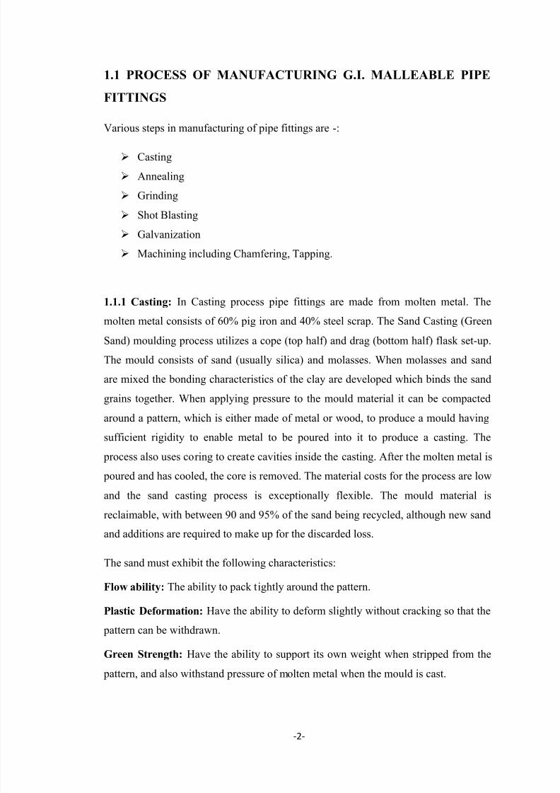
1.1.1 Casting: In Casting process pipe fittings are made from molten metal. The
molten metal consists of 60% pig iron and 40% steel scrap. The Sand Casting (Green
Sand) moulding process utilizes a cope (top half) and drag (bottom half) flask set-up.
The mould consists of sand (usually silica) and molasses. When molasses and sand
are mixed the bonding characteristics of the clay are developed which binds the sand
grains together. When applying pressure to the mould material it can be compacted
around a pattern, which is either made of metal or wood, to produce a mould having
sufficient rigidity to enable metal to be poured into it to produce a casting. The
process also uses coring to create cavities inside the casting. After the molten metal is
poured and has cooled, the core is removed. The material costs for the process are low
and the sand casting process is exceptionally flexible. The mould material is
reclaimable, with between 90 and 95% of the sand being recycled, although new sand
and additions are required to make up for the discarded loss.
The sand must exhibit the following characteristics:
Flow ability: The ability to pack tightly around the pattern.
Plastic Deformation: Have the ability to deform slightly without cracking so that the
pattern can be withdrawn.
Green Strength: Have the ability to support its own weight when stripped from the
pattern, and also withstand pressure of molten metal when the mould is cast.

7/29/2019 Pipe Line Socket Thesis
http://slidepdf.com/reader/full/pipe-line-socket-thesis 14/81
-3-
Permeability: This allows the gases and steam to escape from the mould during
casting.
The melting process is either carried out in rotary or induction furnace.
Figure: 1.2 Induction Furnace
An induction furnace is an electrical furnace in which the heat is applied by
induction heating of metal. The advantage of the induction furnace is a clean, energy-
efficient and well-controllable melting process compared to most other means of
metal melting. Most modern foundries use this type of furnace and now also more
iron foundries are replacing cupolas with induction furnaces to melt cast iron, as the
former emit lots of dust and other pollutants. Induction furnace capacities range from
less than one kilogram to one hundred tones capacity and are used to melt iron and
steel, copper, aluminium and precious metals. Since no arc or combustion is used, the
temperature of the material is no higher than required to melt it; this can prevent loss
of valuable alloying elements. The one major drawback to induction furnace usage in
a foundry is the lack of refining capacity; charge materials must be clean of oxidation
products and of a known composition and some alloying elements may be lost due to
oxidation (and must be re-added to the melt). Operating frequencies range from utility
frequency (50 or 60 Hz) to 400 kHz or higher, usually depending on the material being melted, the capacity (volume) of the furnace and the melting speed required.
Generally, the smaller the volume of the melts, the higher the frequency of the furnace
used; this is due to the skin depth which is a measure of the distance an alternating
current can penetrate beneath the surface of a conductor. For the same conductivity,
the higher frequencies have a shallow skin depth - that is less penetration into the
melt. Lower frequencies can generate stirring or turbulence in the metal. A preheated,
1-tonne furnace melting iron can melt cold charge to tapping readiness within an hour.
Power supplies range from 10 kW to 15 MW, with melt sizes of 20 kg to 30 tones of

7/29/2019 Pipe Line Socket Thesis
http://slidepdf.com/reader/full/pipe-line-socket-thesis 15/81
-4-
metal respectively. An operating induction furnace usually emits a hum or whine (due
to fluctuating magnetic forces and magnetostriction), the pitch of which can be used
by operators to identify whether the furnace is operating correctly or at what power
level.
1.1.2 Annealing: The pipe fitting material after casting needs to be annealed. It is
very important process in the manufacturing of pipe fittings. The purposes of
annealing are:-
1 To improve ductility
2 To improve malleability
3 To relieve internal stresses
Figure: 1.3 Annealing Furnace
Process: Material is first packed in annealing furnace. The annealing furnace is
generally made from heat resistant material like fire bricks. The material is generally
packed inside rings of steel. The layers of material are separated from each other by
sand which acts as a conductor of heat as well as stops products from sticking to each
other when heated. The material is heated to a temperature of 960 0C. The material is
then held at this temp for about 4-6 hours. The material is then allowed to cool slowly
in the furnace itself. The cooling process takes generally 2-3days.After cooling
process is over and furnace cools to suitable temp, the material is then taken out. The
annealed material is tested for its malleability by the compression test as explained
further.

7/29/2019 Pipe Line Socket Thesis
http://slidepdf.com/reader/full/pipe-line-socket-thesis 16/81
-5-
Compression Test: This test is conducted on the material that has been annealed. It is
conducted to judge the malleability of the pipe fittings and shall be carried out as:
A ring of 10mm width for socket 1ʺ is cut from one end of the unfinished socket after
the annealing process to form a test piece. The outside of the test piece is measured
over the points 450 off mould joints. The test piece shall be placed on the equipment
as shown in FIG 1.4 [A hand vice can be used in place] and shall be compressed
gradually at the rate of 17 to 20mm/min until the amount of compression reaches 5
percent of one original outside diameter. The test should not show any crack on any
part of the work piece.
Figure: 1.4 Equipment for Compression
1.1.3 Grinding: A machine tool operation which is mostly used of finish within close
tolerances flat, cylindrical or other surfaces by the abrasive action of a high speed
grinding wheel is known as Grinding. A machine tool which is usually designed to
finish close tolerances flat, cylindrical or other Surfaces by the abrasive action of a
high-speed grinding wheel is called grinding machine or grinder.
Grinding Action: Grinding wheels are composed of an abrasive material of very high
harness, approaching the hardness of diamond held together by a set adhesive
substance called, a bond. Upon rapid rotation of the grinding wheel, its grainscontacting the work piece remove thin chips from it. The cutting ability of separate
grains varies since the form of grains varies and their sharp cutting edges are arranged
differently. For this reason, the material being ground is cut by certain grains in the
same manner as by the cutting teeth of a milling cutter. Some other grains scrape and
scratch the work. Some grains only rub against the surface of the work piece.
Consequently, in grinding a metal, not only chips of various forms are produced, but a
metallic dust as well is produced .The particles of this dust and pieces of the chips are
cemented together at the high temperature generated in grinding. This temperature is

7/29/2019 Pipe Line Socket Thesis
http://slidepdf.com/reader/full/pipe-line-socket-thesis 17/81
-6-
due to friction of grinding wheel on the ground surface. In grinding without coolant,
the temperature is in the zone where chips cut may reach 2000oC. The harder the
material to be ground, the more rapidly the grains of the grinding wheel will be
dulled. For this reason, wheels, in which the bond presents less resistance to breaking
out of the dulled grains, are used for grinding the harder materials. This facilitates self
sharpening of the wheel.
Figure: 1.5 Grinding Machine
1.1.4 Shot Blasting: Shot Blasting is a process in which an abrasive material is forced
through a jet nozzle using compressed air pressure. This creates a fast and effective
way of cleaning or preparing surfaces for recoating using steel shots. Steel shots are
sharp, hard abrasive which is used to prepare surfaces on non‐ferrous metals before
recoating.
Shot blasting machines incorporate 5 basic elements:
1. One or more wheel units
2. A cabinet that contains abrasive material as it performs its cleaning function.
3. A means of presenting the work to be cleaned the abrasive action.
4. A system to re‐circulate and clean the abrasive, removing sand, fines and
contaminants from the abrasive mix before returning effective abrasive to the blast
wheels.

7/29/2019 Pipe Line Socket Thesis
http://slidepdf.com/reader/full/pipe-line-socket-thesis 18/81
-7-
5. Dust collector to remove all dust and abrasive fines from blast machine to provide
an environmentally safe operating atmosphere.
The wheel: The key component in airless blast cleaning machine is the
abrasive‐throwing wheel. The intensity of the radial and tangential forces it develops,
the abrasive flow volume and velocity it generates, the accuracy and stability of its
blast pattern in the target zone‐all are vital to the effectiveness and economy of the
blast cleaning operation.
Figure: 1.6 Shot Blasting Machine
Blasting: Abrasive from an overhead storage hopper is fed to the centre of the wheel
unit which is rotating at high speed. A cast‐alloy impeller rotates with the wheel and
carries the abrasive to an opening in the stationary control cage form where it is
discharged onto the bladed wheels. At this point, the abrasive is picked up by the
inner ends of the throwing blades and is rapidly accelerated as it moves to the
periphery of the wheel. When the blast wheel is properly adjusted and its elements are in good working
condition, the full effect of the blast stream will be attained for maximum efficiency.
Some of the more common causes and cures of wheel malfunctions are highlighted on
these pages.
Control Cage: One of the most critical components in the wheel is the control cage.
This governs the directions of the blast out of the wheel and onto the work to be
7/29/2019 Pipe Line Socket Thesis
http://slidepdf.com/reader/full/pipe-line-socket-thesis 19/81
-8-
cleaned. As little as 10% misadjustments of the “hot spot” can reduce cleaning
efficiency by 25% or more.
Impeller: Of equal importance in maintaining the desired blast pattern is the effect of
abrasive wear on the impeller. If the leading edge of any segment of the impeller
becomes worn so that it becomes parallel with the blade, the abrasive will cut through
the bottom of the blade and could create wear on the steel spacer and blade slots. Not
only will the blast pattern be affected but also wheel imbalance will result creating
additional serious problems.
Wear Affects Efficiency: Complaints of longer than normal cleaning cycles,
inadequate cleaning and high maintenance costs can usually be traced directly to loss
of directional control over the blast pattern. Of course, the blast pattern must be set
properly in the first place but it can change for a variety of reasons. Wear on the
wheel parts which control the “Hot‐Spot”‐ control cage, impeller and blades – is the
chief cause for changes in this pattern. Inspect them regularly and replace them as
soon as excessive wear is detected.
Ammeter – A Tool to Control Cleaning Efficiency: The ammeter on each Shot
Blasting machine wheel motor is an important tool to help you control cleaning
efficiency. It is the only way of determining at a glance how much abrasive is being
thrown by the wheel. For example, on a typical Shot Blasting machine, with a 19 ½ ʺ
diameter by 2 ½ʺ wide wheels using a 15 HP motor on 440 volts approximately 8
amperes would be used without any abrasive flowing into the wheel. Under full load,
20 amps would be used. The abrasive thrown under full amperage would weigh about
375 pounds per minute or about 31 pounds for each abrasive load ampere. If the
wheel were operating at 17 amps rather than 20, there would be over 25% reduction in
wheel efficiency. When the wheel is operating at less than full amperage (as stamped
on the plate above the ammeter) this usually means there is an insufficient amount of
abrasive in the machine but it may also indicate poor adjustment of the wheel parts, it
is important that the cause of this low amperage be corrected immediately since
longer periods of blasting are required under these conditions to produce the desired
cleaning results.

7/29/2019 Pipe Line Socket Thesis
http://slidepdf.com/reader/full/pipe-line-socket-thesis 20/81
-9-
Wheel Housing: The blast wheel is enclosed within a housing whose primary
function is to serve as a safety guard and abrasive seal around the rapidly rotating
wheel. To minimize wear on the housing, a series of protective liners are installed
inside this housing. The latest protective liner kit, which is recommended for all “M”,
“R” and “RLM” wheels, consist of only nine places. Labyrinth seals provide an
abrasive tight closure between top, side and end liners. The curved top liner
minimizes ricochet of abrasive back into the wheel.
To Reduce Blast Cleaning Wheel Noise: One of the chief sources of noise at the
blast machine is the opening where abrasive is fed to the blast wheel. The Sound
Abator totally enclosed abrasive control valve, which can be installed on most Shot
Blasting machine machines, is specifically designed to combat noise from this source
by sealing the opening to the wheel. It can reduce the noise level of a typical blast
wheel, measured three inches from the abrasive feed inlet, by 25 decibels (A scale).
The Sound Abator also serves another important function by modulating the volume
of abrasive flowing to the blast wheel.
The Abrasive Handling System: Every Shot Blasting machine blast cleaning system
contains the following elements:
1. The abrasive elevator.
2. A device to move abrasive from the elevator and provide preliminary screening of
the abrasive before it enters the separator – this may be by gravity or a screened rotary
screw conveyor.
3. An air wash abrasive separator to remove all dust, fines and contaminants from the
abrasive.
4. A hopper to collect refuse removed for the abrasive.
5. An abrasive control device (Sound Abator) to control and meter flow of abrasive to
the blast wheel.
6. A means of moving spent abrasive, sand and other contaminants to the elevator.
This could be a helicoids screw, shaker conveyor or gravity.
Ventilation and Environmental Protection: Since the blasting action removes sand,
scale, rust, etc. from work and reduces the material removed to varying degrees of

7/29/2019 Pipe Line Socket Thesis
http://slidepdf.com/reader/full/pipe-line-socket-thesis 21/81
-10-
fineness, an adequate and properly operating dust collector system is necessary for
efficient operation of the blast equipment. The predetermined flow of air from each of
the vent points on the Shot Blasting machine must exist for proper operation of the
machine. Although the failure to maintain this flow will soon become obvious
through a reduction in cleaning efficiency and dusting at the machine, a periodic
check on air volumes will preclude the possibility of an unobserved gradual
degradation of operation. The dust collector is also the air source for the abrasive
separator. The condition and efficiency of the dust collector have an important
influence on separator efficiency. When proper ventilation is being experienced at
each venting point, static pressure readings (with a manometer) should be taken in
each of the vent pipes and these readings recorded as standards for future comparison.
Should any future readings show material change in static pressures, it indicates an
upset in the condition of air flow, the cause of which should be investigated
immediately.
Importance of Abrasive: The final element of blast cleaning is the abrasive itself.
Three important factors should be considered to evaluate the performance of the
abrasive:
1. The amount of cleaning the abrasive will do in a given length of time.
2. The quality of the cleaning.
3. The cost of performing a given amount of work.
This performance is determined by abrasive breakdown characteristics, the abrasive
size distribution in the blast machine and the abrasive hardness. Abrasive breakdown
rate affects the shape of the abrasive in the operating mix, and therefore the
maintenance on the blast equipment. Abrasive size distribution is also influenced by
the breakdown rate. The smallest size abrasive possible should be selected for each
job. The size of the abrasive selected, however, is not the factor influencing
consumption. Rather, it is the size at which the abrasive is removed for the machine.
Abrasive hardness is the third major consideration in arriving at proper product
selection. The harder, tougher and more resistant the abrasive, the more useful energy
it will impart to the cleaning task.
When possible, use a low breakdown and high hardness product, characteristics found
in Shot Blasting machine Steel Abrasive, for lowest maintenance costs and maximum
cleaning efficiency.

7/29/2019 Pipe Line Socket Thesis
http://slidepdf.com/reader/full/pipe-line-socket-thesis 22/81
-11-
1.1.5 Hot Dip Galvanization: The galvanizing process consists of three basic steps:
surface preparation, galvanizing and inspection.
Surface Preparation: Surface preparation is the most important step in the
application of any coating. In most instances incorrect or inadequate surface
preparation is generally the cause of a coating failing before its expected service
lifetime. The surface preparation step in the galvanizing process has its own built-in
means of quality control in that zinc simply will not metallurgically react with a steel
surface that is not perfectly clean. Any failures or inadequacies in surface preparation
will immediately be apparent when the steel is withdrawn from the molten zinc
because the unclean areas will remain uncoated and immediate corrective action must
be taken. Surface preparation for galvanizing typically consists of three steps: caustic
cleaning, acid pickling and fluxing.
Caustic Cleaning: A hot alkali solution often is used to remove organic contaminants
such as dirt, paint markings, grease and oil from the metal surface. Epoxies, vinyls,asphalt or welding slag must be removed before galvanizing by grit-blasting, sand-
blasting or other mechanical means.
Pickling: Scale and rust normally are removed from the steel surface by pickling in a
dilute solution of hot sulphuric acid or ambient temperature hydrochloric acid.
Surface preparation also can be accomplished using abrasive cleaning as an
alternative to or in conjunction with chemical cleaning. Abrasive cleaning is a process
whereby sand, metallic shot or grit is propelled against the steel material by air blasts
or rapidly rotating wheels.
Fluxing: Fluxing is the final surface preparation step in the galvanizing process.
Fluxing removes oxides and prevents further oxides from forming on the surface of
the metal prior to galvanizing. The method for applying the flux depends upon
whether the galvanizer uses the wet or dry galvanizing process.

7/29/2019 Pipe Line Socket Thesis
http://slidepdf.com/reader/full/pipe-line-socket-thesis 23/81
-12-
In the dry galvanizing process (see Figure 1.7), the steel or iron is dipped or pre-
fluxed in an aqueous solution of zinc ammonium chloride. The material is then dried
prior to immersion in molten zinc. In the wet galvanizing process, a blanket of liquid
zinc ammonium chloride is floated on top of the molten zinc. The iron or steel being
galvanized passes through the flux on its way into the molten zinc.
Figure: 1.7 Dry Galvanizing Process
Galvanizing: In this step, the material is completely immersed in a bath consisting of
a minimum of 98% pure molten zinc. The bath temperature is maintained at about 840
0F (449 0C). Pipe Fittings items are immersed in the bath until they reach bath
temperature. The zinc metal then reacts with the iron on the steel surface to form a
zinc/iron inter-metallic alloy. The articles are withdrawn slowly from the galvanizing
bath and the excess zinc is removed by draining, vibrating and/or centrifuging. The
metallurgical reactions that result in the formation and structure of the zinc/iron alloy
layers continue after the articles are withdrawn from the bath, as long as these articles
are near the bath temperature. The articles are cooled in either water or ambient air
immediately after withdrawal from the bath. Because the galvanizing process involves
total material immersion, it is a complete process; all surfaces are coated. Galvanizing
provides both outside and inside protection for hollow structures. The galvanizer’s
ability to work in any type of weather allows a higher degree of assurance of on-time
delivery. Working under these circumstances, galvanizing can be completed quickly
and with short lead times. Two- or three-day turnaround times for galvanizing are
common.

7/29/2019 Pipe Line Socket Thesis
http://slidepdf.com/reader/full/pipe-line-socket-thesis 24/81
-13-
Inspection: The two properties of the hot-dip galvanized coating that are closely
scrutinized after galvanizing are coating thickness and coating appearance. A variety
of simple physical and laboratory tests may be performed to determine thickness,
uniformity, adherence and appearance. Products are galvanized according to IS 6745-
1972. The mass of zinc coated pipe fittings is determined by stripping method as
explained:
Stripping Solution: Dissolve 20g of antimony trioxide (Sb2O3) or 32g of antimony
trichloride (SbCl3) in 1000ml of concentrated hydrochloric acid (sp gravity 1.16).
Immediately before test, prepare the stripping solution by adding 5ml of the solution
prepared under to 100ml of concentrated hydrochloric acid (sp gravity 1.16). Mix
well.
Procedure: Weigh the cleaned test piece whose mass is less than 200 g nearest to
0.01 g, for test piece whose mass is between 300 to 1000 g, weigh to nearest 0.1 g and
for masses over 1000 g, the accuracy of weighing shall be nearest to 0.5 g. After
weighing immerse each test piece singly in test solution prepared and allow remaining
there until the violent evolution of hydrogen ceases, and only a few bubbles are being
evolved. This requires about 15 to 30 seconds except in the case of sherardizedcoatings which require somewhat longer time.
Calculation
Where
M=mass of zinc coating in g/m2of surface,
M1=original mass in g of the test piece,
M2=mass in g of the stripped test piece, and
t= thickness of the stripped test piece in mm.
Performance of Galvanized Coatings: Galvanized coatings have a proven
performance under numerous environmental conditions. The corrosion resistance of
zinc coatings is determined primarily by the thickness of the coating but varies with
the severity of environmental conditions. Environments in which galvanized steel and

7/29/2019 Pipe Line Socket Thesis
http://slidepdf.com/reader/full/pipe-line-socket-thesis 25/81
-14-
iron are commonly used include indoor and outdoor atmospheres, the storage of
hundreds of different chemicals, in fresh water, sea water, soils, and/or concrete.
Because of the many years galvanizing has been used for corrosion protection, a
wealth of real-world, long-term exposure data on zinc coating performance in a wide
variety of environments is available.
Atmospheric Exposure: Zinc oxide is the initial corrosion product of zinc in
relatively dry air. This is formed by a reaction between the zinc and atmospheric
oxygen. In the presence of moisture, this can be converted to zinc hydroxide. The zinc
hydroxide and zinc oxide further react with carbon dioxide in the air to form zinc
carbonate. The zinc carbonate film is tightly adherent and relatively insoluble. It is
primarily responsible for the excellent and long-lasting corrosion protection provided
by the galvanized coating in most atmospheric environments. Exposure atmospheres
may be divided into five types. They are:
Moderately Industrial: These environments generally are the most aggressive in
terms of corrosion. Air emissions may contain some sulphides and phosphates that
cause the most rapid zinc coating consumption. Automobile, truck and plant exhaust
are examples of these emissions. Most city or urban area atmospheres are classified as
moderately industrial.
Suburban: These atmospheres are generally less corrosive than moderately industrial
areas. As the term suggests, they are found in the largely residential perimeter
communities of urban or city areas.
Temperate Marine: The service life of galvanized coatings in marine environments
is influenced by proximity to the coastline and prevailing wind direction and intensity.
In marine air, zinc corrosion follows a different mechanism; chlorides from sea spray
can react with the normally protective zinc corrosion products to form soluble zinc
chlorides. When these chlorides are washed away, fresh zinc is exposed to corrosion.
The addition of calcium or magnesium salts to the surface of the zinc can extend the
service life of the coating.

7/29/2019 Pipe Line Socket Thesis
http://slidepdf.com/reader/full/pipe-line-socket-thesis 26/81
-15-
Tropical Marine: These environments are similar to temperate marine atmospheres
except they are found in warmer climates. Possibly because many tropical areas are
often relatively far removed from heavy industrial or even moderately industrial areas,
tropical marine climates tend to be somewhat less corrosive than temperate marine
climates.
Rural: These are usually the least aggressive of the five atmospheric types. This is
primarily due to the relatively low level of sulphur and other emissions found in such
environments.
Corrosion Performance in Fresh Water: Galvanizing is successfully used to protect
steel in fresh water exposure. “Fresh water” refers to all forms of water except sea
water. Fresh water may be classified according to its origin or application. Included
are hot and cold domestic, industrial, river, lake and canal waters. Corrosion of zinc in
fresh water is a complex process controlled largely by impurities in the water. Even
rain water contains oxygen, nitrogen, carbon dioxide and other dissolved gases, in
addition to dust and smoke particles. Ground water carries microorganisms, eroded
soil, decaying vegetation, dissolved salts of calcium, magnesium, iron, and
manganese, and suspended colloidal matter. All of these substances and other factors
such as pH, temperature and motion affect the structure and composition of the
corrosion products formed on the exposed zinc surface. Relatively small differences
in fresh water content or conditions can produce relatively substantial changes in
corrosion products and rate. Thus, there is no simple rule governing the corrosion rate
of zinc in fresh water. Hard water is much less corrosive than soft water. Under
conditions of moderate or high water hardness, a natural scale of insoluble salts tends
to form on the galvanized surface. These combine with zinc to form a protective
barrier of calcium carbonate and basic zinc carbonate.
Corrosion Performance in Soils: More than 200 different types of soils have been
identified and are categorized according to texture, colour and natural drainage.
Coarse and textured soils, such as gravel and sand, permit free circulation of air, and
the process of corrosion may closely resemble atmospheric corrosion. Clay and silt
soils have a fine texture and hold water, resulting in poor aeration and drainage. The
corrosion process in such soils may resemble the corrosion process in water.

7/29/2019 Pipe Line Socket Thesis
http://slidepdf.com/reader/full/pipe-line-socket-thesis 27/81
-16-
1.1.6 Machining: After galvanization, the pipe fittings are chamfered. Then sockets
are threaded with the help of taps. In this way entire manufacturing process is over.
1.2 TERMINOLOGY:
Various terms used in pipe fitting are as given below:-
Fittings- The connecting pieces connecting one or more parts.
Equal Fittings- Where all outlets are of the same size.
Unequal Fittings- When two or more outlets are of different size irrespective
of the number of outlets.
Male Fittings- Fittings having only male threads.
Female Fittings- Fittings having female threads on the outlet.
Male-Female Fittings- Fittings having male and female threads at the outlets.
Reinforcement- An additional material at the outside diameter of an internallythreaded fitting in the form of band or bead.
Rib- Locally of axially aligned additional material on the outside or inside of a
fitting for assistance in the assembly or manufacturing.
Run- Two principal axially aligned outlets of a tee or cross.
Branch- Side outlet(s) of a tee or cross.
Chamfer- Removal of a conical portion at the entrance of a thread to assist
assembly and prevent damage to the start of the thread.
Face-to-Face Dimension- Distance between two parallel faces of axially
aligned outlet of a fitt ing.
Face-to-Centre Dimension- Distance from the face of an outlet to the central
axis of angularly disposed outlet.

7/29/2019 Pipe Line Socket Thesis
http://slidepdf.com/reader/full/pipe-line-socket-thesis 28/81
-17-
Centre-to-Centre Dimension- Distance between the two parallel central axis
of the outlet of a fitting.
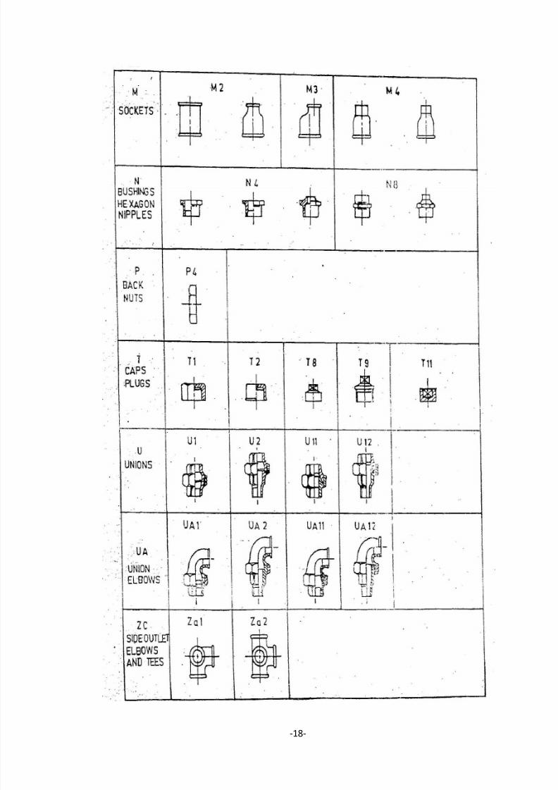
1.3 TYPES OF FITTINGS:
It is denoted as elbow, bend, tee, cross, etc. the diagrammatic representation of the
various types of fittings is given in table-1.3.1
Table 1.3.1: Type of Fittings [26]
7/29/2019 Pipe Line Socket Thesis
http://slidepdf.com/reader/full/pipe-line-socket-thesis 29/81
-18-
7/29/2019 Pipe Line Socket Thesis
http://slidepdf.com/reader/full/pipe-line-socket-thesis 30/81
-19-
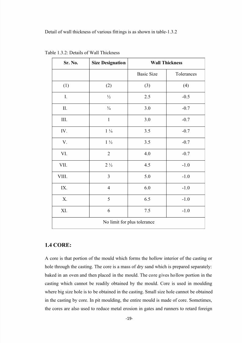
Detail of wall thickness of various fitt ings is as shown in table-1.3.2
Table 1.3.2: Details of Wall Thickness
Sr. No. Size Designation Wall Thickness
Basic Size Tolerances
(1) (2) (3) (4)
I. ½ 2.5 -0.5
II. ¾ 3.0 -0.7
III. 1 3.0 -0.7
IV. 1 ¼ 3.5 -0.7
V. 1 ½ 3.5 -0.7
VI. 2 4.0 -0.7
VII. 2 ½ 4.5 -1.0
VIII. 3 5.0 -1.0
IX. 4 6.0 -1.0
X. 5 6.5 -1.0
XI. 6 7.5 -1.0
No limit for plus tolerance
1.4 CORE:
A core is that portion of the mould which forms the hollow interior of the casting or
hole through the casting. The core is a mass of dry sand which is prepared separately:
baked in an oven and then placed in the mould. The core gives hollow portion in the
casting which cannot be readily obtained by the mould. Core is used in moulding
where big size hole is to be obtained in the casting. Small size hole cannot be obtained
in the casting by core. In pit moulding, the entire mould is made of core. Sometimes,
the cores are also used to reduce metal erosion in gates and runners to retard foreign

7/29/2019 Pipe Line Socket Thesis
http://slidepdf.com/reader/full/pipe-line-socket-thesis 31/81
-20-
matter in the melt and to provide a cap on the top of the mould.
1.4.1 Characteristics of Cores: The core should be sufficiently strong and hard so
that it may be able to support its own weight and withstand force of molten metal.
It should be permeable to escape core gases.
It should be able to withstand high temperatures of the molten metal.
It should be capable of collapsing shortly after the molten metal has solidified
around it.
It should produce minimum amount of gas when in contact with molten metal.
1.4.2 Core Making: The cores are made separately in a core box. The core boxes are
made of wood or metal and designed in several types to aid in-core removal. The
various steps in core making are ramming of core sand in the box, venting,
reinforcing, removing of core from the box, baking, pasting and sizing. The cores are
made either by hand or by machines designed for this purpose. The cores of
symmetrica1 cross-section can be made by extruding core sand mixture through a
suitable die opening. Usually the cores are made by core blowing machine for
production work.
1.4.3 Core Baking or Core Drying: After making the cores, they are dried to drive
off the moisture and to harden the binder. The cores are dried in ovens equipped with
drawers, shelves or other holding devices. They are dried in batches or continuously
over moving shelves. The heat in oven is produced by burning oil or by electric
resistance. The core drying time depends upon the quantity of moisture and binder
used in the sand, size of the core and temperature of the oven.
1.5 CORE MATERIALS:
Dry sand cores are usually made of clear river sand which is mixed with a binder and
then baked to give the desired strength.
1.5.1 Core Sand: Core sand must have the proper type of strength, porosity or
permeability, smooth surface and sufficient refractoriness. Strength depends on the
type of sand and binding material used. Sharper grains of sand will bond together and
form a stronger core. Porosity or permeability depends on the size of the sand grain
and its freedom from fines in between grains. Smooth surface of a core results in a
7/29/2019 Pipe Line Socket Thesis
http://slidepdf.com/reader/full/pipe-line-socket-thesis 32/81
-21-
smooth surface of the opening in the casting. In the attempt to produce a smooth
surface, care must be used not to go too far since permeability is lost as the fineness of
the sand increases. Refractory property is possessed by sand to a great extent. A
binder must be selected that will withstand the temperature required of the core. A
thin coating of graphite or similar material adds considerably to its ability to
withstand the intense heat momentarily.
It is not desirable to have the core remain hard after the metal has cooled. The binding
material used should disintegrate or be burn out by the prolonged contact with the hot
metal so that the core may be removed easily from the finished casting. This so
prevents shrinkage cracks during cooling.
1.5.2 Core Binders. It has already been stated that silica sand is used for preparing
cores. This sand has no natural bond. Hence some other materials are added to it
which acts as binders. The binder cement the sand grains and give sufficient strength
to cores to prevent breakage, distortion, erosion during core making, moulding and
casting.
Various commercial binders are available in the market like core oil, resins, sulphite,
liquor, molasses and proteins. The core oil mainly contains vegetable oil like linseed
oil or corn oil. Core oils are very economical and produce better cores. Rosin and
pitch are thermoplastic binders. The powdered binder is mixed with the core-sand. On
heating, the binder liquefies and coats the grain sands. On cooling the dispersed liquid
binds the sand grains together fulfilling a united mass. Rosin is a form of resin.
Petroleum and coal for resins are also used as binders. Pitch compounded with dextrin
and steam coal is used for large cores. Phenol and urea-formaldehyde, thermosetting
plastic core binders are more suitable. Molasses give hardness to the core but lacks in
strength.
Protein binders like gelation, glue, casein, etc. are used where easily collapsible cores
are required. Sulphite liquor is used where high strength, hardness, quick drying and
high temperature resistance is required.
1.6 CORE SANDS WHICH REQUIRE HEAT TREATMENT:
For the strengthening of cores include oil-bonded, clay-bonded, and resin-bonded
sand mixture (the bonding resins in the last type of sand are fast-curing synthetic

7/29/2019 Pipe Line Socket Thesis
http://slidepdf.com/reader/full/pipe-line-socket-thesis 33/81
-22-
resins). Oil-bonded and clay-bonded core sands show satisfactory properties are
comparatively cheap and suitable for use in hand and machine production of cores in
sand blowing, jolt and squeeze machines. The cores made from these required thermal
heating to impart strength, which lengthens the production process, lowers the
operating efficiency of the foundry and generates a need for installing driers.
That is why such core sands find application in piecework and short run work. Resin
bounded core sands are made with synthetic resin binders of Class B-1
(carbamidebase), B-3 (lignin) and Class A-I (powdered Bakelite).
These binders are capable of hardening at 230-250°C for a short time (2 or 3 min to
30-50s depending on the composition and size of cores). Catalysts (both organic and
inorganic acids) may be added to speed up the process of curing. The core sand
composition also includes such additives as ferric oxide and crystalline graphite
which improve the heat conduction and increase the specific heat of the sand all
thereby enable the core to heat through and harden more speedily. Other additives
diminish stickiness and improve flow ability. The core sand hardens directly in a
metal core box heated by a gas or by electrical heaters. These are the so-called hot
boxes. The sand hardens as a result of policondensation of a binder (resins of B-1 and
B-3 classes) or its polymerization (powdered Bakelite) the core gains high strength,
up to 100 kgf cm-2 and B-3 class resins have low green strength, they flow easily and
thus readily fill the cavities of complex core boxes. The cores are taken off the boxes
already hard. So the castings show improved dimensional accuracy. The core sands
deform well, shake out with ease from the castings but have insufficient thermal
stability. Resin-bonded sands go into the production of cores of all classes for casting
thin-walled small pieces 150 to 200 kg in mass from iron, steel and non-ferrous
alloys. These sands are prepared from washed sands of the first and second classes,
which are more expensive than common quartz sands; the cost of binders is high too,
400 to 800 rubles per ton. The cores are moulded in complex, costly metal boxes, so
that resin-bonded sands are envisaged for use in high volume and high run production.
In this case it pays to automatize the production process with a view to increasing the
efficiency of manufacture, cutting down the costs and improving the quality of
castings. Along with the sands mentioned above, powdered Bakelite-bonded sands are
used for the manufacture of hollow shell-type cores.

7/29/2019 Pipe Line Socket Thesis
http://slidepdf.com/reader/full/pipe-line-socket-thesis 34/81
-23-
1.7 CORE SAND WHICH DO NOT REQUIRE FOR HEAT
TREATMENT
Core sands which do not call for heat treatment are most promising since they allow
the foundry to dispense with the heating of boxes and to simplify substantially the
production process and moulding equipment. Cores can be made in wooden, plastic
and metal core boxes. These sands are highly suitable for use in various types of
production.
Synthetic resin-bonded cold-curing core sands contain such binders as carbamide,
carbamide-furan, phenol-furan; phenol formaldehyde resins (binders of B-1 class).
Catalysts are added to speed up the hardening of binders. These are commonly
organic and inorganic acids such as benzenesulphonic, orthophosphoric and nitricacids. The core sands feature high flow ability and strength from 14.7 to 15.20 kgf
cm-2 and also good gas permeability, deformability and collapsibility.
An important characteristic of a sand mixture is its life that is the time during which
the sand still remains mouldable. The life of sands can be controlled by varying the
amount of catalyst added to the sand. As the quantity of catalyst increases, the sand
life shortens. So, knowing the time it takes to fill the box and ram the sand, we can
add such an amount of catalyst as is necessary to provide the desired span of life for
the sand. As the sand hardens, its strength gradually grows. The rate of strength
growth is directly proportional to the added amount of catalyst. The maximum value
of strength for the given sand decreases with the increased quantity of catalyst.
As the thermal stability of sand decreases, burning-on becomes more probable.
Phenolic and phenol-furan resins feature the highest thermal stability and make
suitable binders of sands for steel castings. Carbamide-furan resins have lower
thermal stability. They serve as binders of iron core sands. Carbamide resins have the
lowest thermal stability. These are the binders of core sands for casting non-ferrous
alloys.
Cold curing sands has a lower strength than sands curable in hot boxes and therefore
they largely go into the production of cores of the third and fifth classes. The setting
time these sands take until they acquire a maximum strength comes to few hours. The
merit of cold-curing sands is they allow for the production of cores in wooden, plastic,
and metal boxes. That is why they have found the widest applications in the batch
production of moderate sized and large sized castings from iron and steel. The use of

7/29/2019 Pipe Line Socket Thesis
http://slidepdf.com/reader/full/pipe-line-socket-thesis 35/81
-24-
these sands makes it possible to exclude drying, mechanize the core production
process, improve the quality of castings and increase the output.
Cold-curing silica-bonded sands include core sand mixtures with a liquid silica glass
as a binder. The cores are dried by blowing carbon dioxide through the rammed sand.
They can also harden under heat. The core sands have high strength, good gas
permeability, but show lowed formability and poor collapsibility. Sawdust
(aboutl.5%) and asbestos powder (up to 5 %) make the cores more deformable and
collapsible. These core sands are applicable in the piece and batch production of steel
and iron castings.
Liquid self-set core sands which compare in properties to the previously described
sands have come into extensive use in the batch production of large castings. The use
of these sands enables the foundries to raise the output per man-hour, mechanize the
process of production of cores for casting parts both piecemeal and in small lots and
improve the quality of castings
1.8 WASHES, PASTES, POWDERS AND OTHER DRESSINGS:
Core and mould washes and pastes are called upon to prevent metal penetration or
burning -on, increase the surface strength, decreases the crumbliness of mould and
core walls and provide clean surfaces and smooth casting appearance. Anti-
penetration washes consist of refractory materials which form the base and binding-
agents. The washes applied to the surface of mould and cores form a strong refractory
coating which keeps the molten metal and its oxides from penetrating into pores
between sand grains and thus eliminates the burnt- on-effect.
1.8.1 Moulding Washes: These paints must conform to the following requirements:
(l) Have a high melting temperature to sand up to the fusion effect of contactingmetal.
(2) Produce no fusible compositions when in contact with the metal.
(3) Remain invariable in composition during preparation, storage and when in use.
(4) Have good covering capacity.
(5) Form a strong skin on mould and core walls, free of cracks after drying.
(6) Firmly adhere to the mould. . .
(7) contain as little foreign matter and difficulty available materials as possible.
The choice of washes depends on the kind of metal cast, mass of the casting and

7/29/2019 Pipe Line Socket Thesis
http://slidepdf.com/reader/full/pipe-line-socket-thesis 36/81
-25-
moulding method. Washes for large iron castings contain such anti-penetration
materials as black lead with the additions of bentonite and binders: In washes for
small and medium size iron castings, silica flour mixed with coal and ground coke
substitutes for graphite. Washes for steel castings usually consist of silica flour or
zirconium silicate which serves as a refractory base, mixed with the same-binders as
those used for iron castings.
In casting iron parts, it is advisable to add 5% coal and charcoal dust to the wash in
order to create-a reducing atmosphere in the mould; silica flour, graphite and ground
anthracite account for 95% of this reducing wash.
The compositions of washes for moulds and cores of iron castings are described here.
The steel moulding washes of the 2nd, 3rd and 4th types are put to use for cores in
castings steel parts with walls 20 to 40 mm in thickness. In painting cores or moulds,
it is advisable to stir the wash regularly to make it stay in suspension. When applying
the wash on cores by dipping, one should shake off the excess of wash to avoid
influxes and insure against sealing of the vents, it is good practice to check the coat
tightness and its surface hardness by applying the wash to sample moulds and cores or
to standard specimens. To enable a better sticking of the wash to the surface of
moulds and cores, foundries make use of priming paints consisting of 25% lignin,
75% water and 25% pectic gel. The paints are applied by the common methods. Air -
drying washes speed up the process of drying of coated moulds and cores. The
composition of a wash of this type includes 10% crystalline graphite, 12% black lead,
3.5% polyvinyl butyral and 74.5% solvent 646 (or a solution of ethyl acetate and
alcohol in the proportion 1. to 1). This wash is applied to moulds and cores for iron
castings. In the wash used for steel castings, graphite is changed by zircon.
1.8.2 Pastes: If washes do not give a sufficiently smooth casting surface nor ensure
the desired dimensional accuracy of casting, it can be useful to apply pastes on to the
surface of cores to exclude surface blemishes. Pastes find rare uses, however, because
they involve manual labour. Coating pastes are made anhydrous. They usually consist
of four parts crystalline graphite and one part vegetable oil (by volume). Sometime
lignin serves as a binder Instead of the expensive oil and talc together with graphite
makes the base. After applying the paste, the cores are dried at 220-240°C.It is
advisable to use oil-free pastes of the following composition (% by mass): 50% talc,
15% chamotte, 25% crystalline graphite, and 15% clay. The dry powder is then

7/29/2019 Pipe Line Socket Thesis
http://slidepdf.com/reader/full/pipe-line-socket-thesis 37/81
-26-
dissolved in 0.6 or 0.51 of water per kg dry mass. If the paste is applied to a hot core,
the coat does not require additional drying.
1.8.3 Putties: These find use for repairing purposes and for sealing seams which may
form while cementing the cores. It is only the cores which have small cracks and
dents in unimportant places that are subject to repair. The cores with open fissures and
large fractured parts are considered non-repairable. The putty of the following
composition is most popular: 65% grade 2KOO63 sand, 25% crystalline graphite, and
10% moulding clay screened through No. 016 sieve. The ingredients-are properly
mixed, and the mass is then blended with water (O.31kg water for 1 kg powder);
powdered soap is added in an amount of 0.5% by mass to give plasticity. Puttyapplied to the cores for steel castings consists of 40% refractory clay, 30% silica flour
and 30% quartz sand; the powder is then mixed with 12% lignin and 13% water.
1.8.4 Core Cements (Pastes): These serve to .bond together core boxes. The
composition commonly includes water-soluble binders, clay and bentonite. In wide
use are the core pastes of the following compositions:
(1) 0.50% lignin, 50% moulding day, 20% water (the rupture strength of dry paste is
not less than 685 kPa, or kgf cm-2);
(2) 40% dextrin and 60% clay mixed with water (65 parts water to 100 parts by mass
of powder).
1.8.5 Parting Powders and Dusts: Patterns and core boxes are dusted with facings to
prevent the moulding sand from sticking to their surfaces. Powders for in a water-
impermeable coat and thus exclude sand adhesion. Foundries use a lycopodium
powder and its substitutes for the purpose.
The lycopodium powder is a white to yellow substance which is light in mass, fluid
and fine-grained (it fully passes through No. 0063; No. 055 catches 5% powder). This
powder is costly and not readily available.
1.8.6 Artificial Dusts: (substitutes for lycopodium powder) are produced from fine
powders of tripoli, dolomite and other similar materials. The powders are treated with
paraffin, fat, and wax to provide a thin film on powder grains. Other materials which
prevent sand sticking are kerosene with crystalline graphite or the mixture of 10%

7/29/2019 Pipe Line Socket Thesis
http://slidepdf.com/reader/full/pipe-line-socket-thesis 38/81
-27-
oleic acid and 90% kerosene. Heating a pattern plate to 40°C also helps eliminate
sticking. The film of kerosene on the pattern surface precludes its moistening with
water and thus excludes sand adhesion. For economy, the mixture may consist of 50%
kerosene and 50% black oil. Heating the tern dries its Surface and thus impedes
moisture condensation if the sand is still hot.
1.9 CORE FRAMES:
These are the reinforcement means moulded into cores to increase strength. The
frames are made from wire or shaped cast iron plates. The core--reinforcement must
fulfil the following requirements: give sufficient strength and rigidity to the core, not
spring or come off the core sand (soft, annealed wire will do for the purpose), deform
readily to allow for contraction of the casting, not stand in the way of vent holes being
made and permit easy shakeout of the core from the casting.Thin cores are reinforced
with I or 12 mm wire inserted into the core boxes during core moulding. Small and
moderately sized cores are made with 6 to 10 mm wire frames whose separate parts
are fastened with a thinner wire. The reinforcement means for large sand-clay cores
are iron and steel cast frames with 6 to 10 mm cast in wire inserts.
The framework for medium-sized and large cores includes lifting arrangements by
which the cores are suspended on the crane for delivering them to the assembly site.
Wire and cast frames are made in various shapes. Wire frames are laid along the
length in the core. They should terminate at least 2 or 3 mm short of the core ends.
The frame should pass into the prints to add to the core strength. If the core has two
prints located opposite each other the frame should extend into both.
The wire that makes up the frame proper is the basic wire and which runs around the
frame periphery and strengthens individual parts of the core is the binding wire. It is
impermissible to place the frame wire too close to or directly on the surface or the
core otherwise the frame may weld to the casting and cause the formation of
blowholes and hot tears. The distance from the wire frame to the core surface must be
5 to 10 mm. For cast frames, this distance in cores measuring 500 x 500 mm, (500 -
1000) x (500 - 1000) mm and over 1000 x 1000mm ranges from 20 to 30 mm, 25 to
30 mm and from 30 to 35 mm respectively.
If a core should have only one frame, this is placed in the centre of its cross section.
Several frames should be positioned uniformly over the core cross section. If a core

7/29/2019 Pipe Line Socket Thesis
http://slidepdf.com/reader/full/pipe-line-socket-thesis 39/81
-28-
has a curved axis, it is better to set up a few thin frames instead of a single thick frame
in order to facilitate the core shakeout from the casting. It is undesirable to use core
reinforcement in the mass production of castings since this complicates the core
making process and the core shake out procedure. The required strength of cores is
often possible to achieve by using high strength core sand.
1.9.1 Making a Large Core in Turnout Core Box with Loose Side: In the
preliminary operations, the core maker first prepares a cast frame (grid) for core
moulding. For this, he bends wire about the contour of the core working cavity and
checks it for the right position by inserting the frame into the box. After this done, he
cleans the box of the adhered sand, wipes its working surface with a kerosene-moisten
drag, fills the box with core sand to a depth of 50 - 70 mm and rams it.
The core maker now inserts the clay coated frame into the box and sets up steel pins
or hooks to reinforce the protruding and narrow portions of the core. Then he lines the
working surface of the box with core sand and rams it into narrow pockets and
recesses. Next he inserts into the box, a wooden piece to form a cavity for coke ash
and fills the box around the wooden piece with sand and compacts it. The core maker
then removes the piece, makes vent holes, fills the cavity with coke ash and sand and
rams the core. Using the necessary handling equipment, he places a drying plate on
the top and inverts the box.
Further, the core maker raps the box to facilitate the removal of the upper part. After
this is done; he gently takes aside loose pieces of the box. Now he finishes up the
core, checks it for compactness, repair the portions damaged in the core removal
operation, rounds off and fillets sharp angles and inserts metal pins into thin parts and
at corners. The finished core is conveyed for drying and then for coating.
1.10 MACHINE CORE MAKING:In the mass and large-lot production of castings, cores are made on core making
machines which at present are progressively introduced into foundries producing
castings in small lots. Core making machines increase the productivity of labour,
make easier the work of operators and produce cores of high accuracy, largely from
sands of lowered green strength which flow readily into deep pockets of the box.
There is a variety of core making machines available to the foundry such as core
blowing, slinging, jarring, squeezing, core shooter, screw-feed (extrusion) types and
others.

7/29/2019 Pipe Line Socket Thesis
http://slidepdf.com/reader/full/pipe-line-socket-thesis 40/81
-29-
CHAPTER: 2
LITERATURE REVIEW
A comprehensive review of the work reported by various researchers in the field of improving productivity of castings is described as
C. Li and B. G. Thomas [2000] investigated the theoretical limits of the shell
thickness, casting speed, and productivity of the steel continuous casting process as a
function of steel grade, section size, and mould length, assuming ideal liquid flux
lubrication. The predictions are based on the maximum casting speed that is just able
to produce a thin shell with the critical thickness needed to withstand the ferrostatic
pressure below the mould and avoid a longitudinal rupture from excessive creep stain.
The calculations are performed with a finite-element thermal-stress model that has
been validated with numerical solutions and plant data. The critical shell thickness is
predicted to be on the order of 3 mm. It is surprisingly insensitive to steel grade and
superheat, but decreases with decreasing section size and increasing working mould
length. The theoretical maximum casting speed and potential productivity both
increase with decreasing critical shell thickness. The theoretical limits to casting
speed are predicted to be extremely high, exceeding 21 m/min for a conventional 700-
mm working mould length, 200-mm square bloom mould, which corresponds to 3.5
million tonnes / year. The infeasibility of these limits in practice is likely due to other
problems such as achieving shell thickness uniformity and liquid flux lubrication.
Attention should return to focussing on these other problems which limit productivity.
This work suggests that if shortening mould length can solve lubrication, taper, and
other problems, then it should be explored as a potential means to increase
productivity. A uniform shell would be strong enough to withstand the ferrostatic
pressure even with a shorter mould length and a higher casting speed. To overcome
the other problems which limit casting speed and productivity, design changes
regarding fluid flow, mould powder, mould taper, and machine length are also
required. This should be the concern of the designers of future continuous casting
processes.

7/29/2019 Pipe Line Socket Thesis
http://slidepdf.com/reader/full/pipe-line-socket-thesis 41/81
-30-
Thomas Schroeder [2004] reviewed the formulations of starch and dextrin based
adhesives used in making cores. Various advantages of these adhesives are
availability and low costs, stability of quality, insolubility in oils and fats, non-toxic
and biodegradable nature, heat resistance.
Nicolas Perry, Magali Mauchand, Alain Bernard [2004] described that the costs
controls is a major decision tool in the competitiveness of the companies. After
defining the problems related to this control difficulties, they presented an approach
using a concept of cost entity related to the design and realization activities of the
product. They tried to apply this approach to the fields of the sand casting foundry.
This work high lightened the enterprise modelling difficulties (limits of a global cost
modelling) and some specifics limitations of the tool used for this development. A
Cost Entity is a grouping of costs associated with the resources consumed by an
activity.
L.A. Dobrazański, M. Krupiński, J.H. Sokolowski, P. Zarychta and Wlodarczyk -
Fligier [2006] presented methodology of the automatic quality based on analysis of
images obtained with the X-ray defect detection, employing the artificial intelligence
tools. The methodologies developed made identification and classification of defects
possible and the appropriate process control made it possible to reduce them and to
eliminate them at least in part. The reduction of defects in casting resulted in increase
of productivity.
J. Dańko, M. Holtzer, R. Dańko [2007] presented a paper which dealt with such
problems of scientific and development research concerning the reclamation of used
foundry sands as: management of used sands generated in foundry production,
recommendation of selection of effective reclamation techniques and assessment
methods of the reclaimed material quality, identification methods and an
environmental impact assessment of spent sands from foundry technologies, moulding
and core sands of an increased reclamability and a decreased harmfulness for
environment. The reclamation of used sand helps in increasing productivity.
7/29/2019 Pipe Line Socket Thesis
http://slidepdf.com/reader/full/pipe-line-socket-thesis 42/81
-31-
A. Fedoryszyn [2007] observed that an increase of productivity requires a wide-scale
mechanisation of the equipment used for casting production on modern foundry
moulding lines. Modernisation of foundries is expected to help in creation of optimum
conditions for casting production, satisfying all the requirements regarding quantity
and quality of castings produced. Modern designs of moulding lines were described,
including moulding machines and the related equipment.
F. Peters, R. Voigt, S. Z. Ou and C. Beckermann [2007] described that steel
castings produced in sand moulds, the expansion of the sand has a significant impact
on the final size and shape of the casting. Experiments were conducted using a
cylindrical casting to study this effect for different sands (silica and zircon) and
different sand binder systems (phenolic urethane and sodium silicate). The type of
sand has a significant effect on the final casting dimensions, in particular because the
expansion of silica sand can be irreversible. The sand expansion effect is enhanced by
the presence of sodium silicate binder. In addition, the size of the core strongly affects
the internal and external dimensions of the resulting casting.
Liu Weihua, L i Yingmin, Qu Xueliang, Liu Xiuling [2008] proposed productivity
improvement by preparing a new aqueous alkaline resol phenol-formaldehyde resin
from phenol and formaldehyde using NaOH as catalyst; With addition of some cross-
linking agents, after passing carbon dioxide gas through the resin bonded sand, high
as-gassed strength and 24 h strength are achieved.
E.O. Olakanmi and A.O. Arome [2009] contributed to productivity improvement by
characterising core-binding properties of beniseed and melon oils with a view to
finding alternatives to the imported foundry core oils that deplete Nigeria’s foreign
exchange. Clay and sand samples collected from Niger and Plateau states respectively
were blended with varying proportions of core-oils in order to assess their functional
properties. Baked strength of 3,223.41 kNm-2 obtained for the oils suggest that the oil
samples can be used as substitute for imported core oil. On the basis of ranking
according to functional properties, beniseed oil was found to possess more desirable
functional properties in terms of bulk density, strength and collapsibility. Practical
applications of these core oils reveal that they are suitable for castings of large,
medium and small sizes. On the basis of results obtained in this study both beniseed

7/29/2019 Pipe Line Socket Thesis
http://slidepdf.com/reader/full/pipe-line-socket-thesis 43/81
-32-
oil and melon oil can be used as substitutes for imported core oils like linseed oil,
corn oil and fish oil. Beniseed core oil binder was found to be the most desirable for
core making because it was able to impart higher bulk density, green and baked
strength to the core mixes. Moreover, its collapsibility was faster than that of the
melon core oil binder.
Slavomír Peľák, Rudolf Mišičko, Dagmar Fedáková, Jana Bidulská [2009]
evaluated the relationships between the chemical composition, the dendrite structure
parameters, the casting technology parameters and the occurrence of defects in
continuously cast slabs. For calculation of the selected indices, the sulphur and
phosphorus content, the overheating temperature, the casting speed, the dendrite arm
spacing, and the central zone share were chosen. These indices determined the
susceptibility of steel to the defect formation. The defects were formed in steels with a
high overheating degree, a low share of central zone, high dendrite arm spacing and
an exceeded recommended sulphur and phosphorus content.
A.K.M.B. Rashid [2010] presented methods of controlling hot tears in casting in
order to increase productivity. He proposed the use of local chilling of hot spots,
reduction in casting temperature to reduce hot tearing. He also suggested that fins are
a major source casting constraint. So casting should be checked straight out of mould,
not after machining.
Lakshamanan Singaramu [2010] The Taguchi method is a powerful problem
solving technique for improving process performance, yield and productivity. Green
sand process involves many process parameters which affect the quality of the
castings produced. An analysis of significant process parameters of green sand casting
process has been made in this paper. The parameters considered were Green strength,
moisture content, permeability and mould hardness. The outcome of the paper was the
optimised process parameters of the green sand casting process which lead to
improved process performance and thus minimum casting defects.
R. Venkataraman [2010] presented innovative ideas for improving foundry
productivity and casting quality. He discussed case studies in areas like design of
product, methoding practice, pattern manufacturing, moulding, core making, meltingand pouring and post processing after casting evaluation. He suggested time study of

7/29/2019 Pipe Line Socket Thesis
http://slidepdf.com/reader/full/pipe-line-socket-thesis 44/81
-33-
processes like drag moulding time, cope moulding time, core setting time, box closing
time and pouring time. Implementation of new ideas is helpful for increasing
productivity by reducing cycle time. Metal spurting can be prevented by a mobile
cover moving along with ladle covering top area of mould. This ensures safety of
people , plant and facilities.
Nishikant M Ejrekar, Vicky Kapur [2011] contributed to productivity improvement
by presenting a practical approach to coating technology in production of high quality
castings. Refractory coatings play an important role in preventing many casting
defects like metal penetration and fusion. The main objective while using a refractory
coating is to apply a uniform coating layer free from runs, drips and cracks.
Anil Barik [2011] discussed effects and controlling measures of directional
solidification in castings towards quality improvements. Directional solidification can
be achieved through use of riser, chills, chaplets, insulating pads and sleeves for
risers, mouldable exothermic sleeves.
O.S.I. Fayomi, O.O. Ajayi and A.P.I. Popoola [2011] investigated the use of local
oils, namely groundnut oil, cotton seed oil and palm oil with Nigeria local clay and
silica sand for the production of foundry cores on varying composition. Addition of
cassava starch, local clay, oil and moisture to sand are used to produce strong and
efficient core. These oils were tested and it was found that the three could be used to
produce foundry cores. The best Composition was found to be core comprising 2.5%
starch, 2.5% clay, 8% oil, 8% moisture and 68% sand and baked at 150oC for 1 h
30min. The tensile strength of the core was as high as 600 KN/m2. The study have
been used to consider the effectiveness and suitability of Nigeria Ochadamu sand and
clay with other bounding binder proportion of groundnut oil, cotton oil, palm oil, and
starch variation. The results showed after tensile analysis that the sand and oils
employed were good binders if baked between temperature of 150 and 200°C and
with 2.5% starch content.
J.S. Colten [2011] suggested solution for various casting defects to increase
productivity. Shrinkage can amount to 5-10% by volume. So part and mould need to
be designed to take this amount into consideration. Porosity is caused due toentrapped gases and shrinkage. Remedies suggested for gas bubbles are controlled

7/29/2019 Pipe Line Socket Thesis
http://slidepdf.com/reader/full/pipe-line-socket-thesis 45/81
-34-
atmosphere, proper venting, and proper design of runners, gates and addition metallic
elements to react with gases. Solutions for porosity/shrinkage are use of runners and
use of chills.
R. Vinayagasundaram, V.R. Nedunchezhian [2012] studied the application of
modern technology in foundries and its impact on productivity and profitability. In
order to produce the cast components in foundries with high quality and at lowest cost
the foundry owners have to introduce modern technology to improve the productivity.
This study brought out how technically qualified entrepreneurs of selected foundries
have carried out technological innovations, mainly due to their self-motivation and
self-efforts. Introducing the modern technology in the process and changing product
designs, as desired or directed by the customers resulted in cost reduction, quality and
productivity improvement. These incremental innovations have enabled the selected
foundries to enhance competitiveness, grow in the domestic market and penetrate the
international market and grow in size over time. And have achieved technological
innovations successfully based on their technological capability and customer needs,
enabling them to sail through the competitive environment.
Bharathi Rajkumar k. and Gukan Rajaram [2012] implemented lean philosophy
in foundry with a spotlight on increasing productivity. The purpose was to develop
kaizens to eliminate waste in the foundry. In this case study, the industry could not
meet the customer requirements due to the increasing cycle time of the individual
process and rework due to excess rejection. Processing time was more in core making,
mould making and finishing section of the foundry. Time study and motion study was
conducted and the respective operation idle time and busy time were taken. This paper
described some of the quality improvement tasks that reduced the rejection rate which
also affect the productivity. The improvement of work process was executed by
eliminating and combining of work process, which reduces production time, number
of process and space utilisation. The results of process were analysed by conducting
time study after implementation with cost benefit analysis to show the financial
benefits.
Noberto T. Rizzo Downes, Ramon D. Duque proposed ten steps for increasing
yield in ductile iron castings. These included use of ceramic foam, shorter gating

7/29/2019 Pipe Line Socket Thesis
http://slidepdf.com/reader/full/pipe-line-socket-thesis 46/81
-35-
systems, non-turbulent gating system gating design, thinner runners and ingates, and
proper and efficient use of risers. Many of these techniques were reported in the
literature. It was suggested that cost-savings achieved by application of these steps
could be significantly higher than those achieved by conventional scrap reduction
procedures.
These researchers have suggested various means to increase productivity in foundry.
These researches emphasize use of easily available core binders, proper composition
of contents of cores to reduce wastage and production cost of cores. Use of refractory
coating on mould and core, use of proper sand binders of mould are other means of
having defect free castings. Vinayagasundaram and Nedunchezhian emphasized the
use of modern technology in foundries to increase productivity. These modern
technologies include – Just in Time, Lean Manufacturing, and Enterprise Resource
Planning. Technological challenges for foundry according to him are optimal design
of pattern and core to minimize scrap.

7/29/2019 Pipe Line Socket Thesis
http://slidepdf.com/reader/full/pipe-line-socket-thesis 47/81
-36-
CHAPTER: 3
PROBLEM FORMULATION
A lot of researches have been done by many researchers in the field of casting. There
is large scope of improvements in this field. Researches in the field of foundry include
core making techniques, use of different type of binders for core making, mould
making techniques, use of different techniques to improve quality of sand casting etc.
Major foundries are producing auto parts, sanitary fittings, pipe fittings and machine
parts. Pipe fitting industry is a small scale industry. Pipe fittings are mainly made of
malleable iron. These products are first casted in foundry. Productivity in these
industries is low because of non-optimal shape of core boxes in which cores are made.
It has been seen that pattern and core makers engaged in these industries are not
technically aware of productivity improvement techniques. So a need is felt to make a
core of optimum shape in order to improve productivity.
OBJECTIVES
Various Objectives of our work are:-
1) To reduce time of chamfering and labour cost.
2) To reduce the cutting tool cost for chamfering.
3) To increase productivity by reducing scrap production due to chamfering.
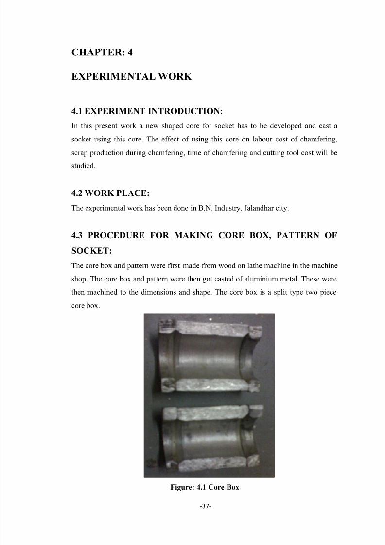
7/29/2019 Pipe Line Socket Thesis
http://slidepdf.com/reader/full/pipe-line-socket-thesis 48/81
-37-
CHAPTER: 4
EXPERIMENTAL WORK
4.1 EXPERIMENT INTRODUCTION:
In this present work a new shaped core for socket has to be developed and cast a
socket using this core. The effect of using this core on labour cost of chamfering,
scrap production during chamfering, time of chamfering and cutting tool cost will be
studied.
4.2 WORK PLACE:
The experimental work has been done in B.N. Industry, Jalandhar city.
4.3 PROCEDURE FOR MAKING CORE BOX, PATTERN OF
SOCKET:
The core box and pattern were first made from wood on lathe machine in the machine
shop. The core box and pattern were then got casted of aluminium metal. These were
then machined to the dimensions and shape. The core box is a split type two piece
core box.
Figure: 4.1 Core Box

7/29/2019 Pipe Line Socket Thesis
http://slidepdf.com/reader/full/pipe-line-socket-thesis 49/81
-38-
Figure: 4.2 Core Box 1ʺ (sectional view)*
Figure: 4.3 Core Box 1 ʺ (sectional view)*
*All dimension are in mm.
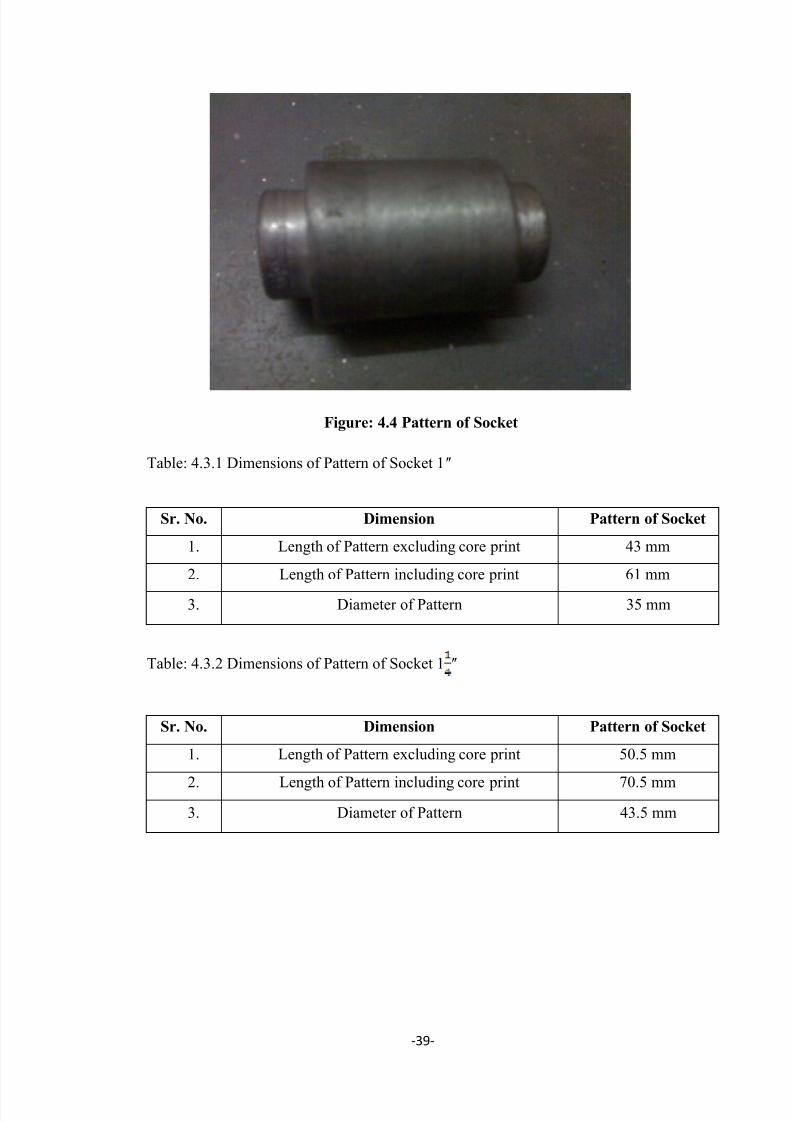
7/29/2019 Pipe Line Socket Thesis
http://slidepdf.com/reader/full/pipe-line-socket-thesis 50/81
-39-
Figure: 4.4 Pattern of Socket
Table: 4.3.1 Dimensions of Pattern of Socket 1ʺ
Sr. No. Dimension Pattern of Socket
1. Length of Pattern excluding core print 43 mm
2. Length of Pattern including core print 61 mm
3. Diameter of Pattern 35 mm
Table: 4.3.2 Dimensions of Pattern of Socket 1 ʺ
Sr. No. Dimension Pattern of Socket
1. Length of Pattern excluding core print 50.5 mm
2. Length of Pattern including core print 70.5 mm
3. Diameter of Pattern 43.5 mm

7/29/2019 Pipe Line Socket Thesis
http://slidepdf.com/reader/full/pipe-line-socket-thesis 51/81
-40-
4.4 MANUAL CORE MAKING:
In the single piece and small-lot production of castings, it is common practice to make
cores manually in core boxes and with the aid of templates. The production of cores in
core boxes is the most widespread method which is rather simple and effective. Firstthe box halves are fastened with clamps and the box is placed vertically on the bench.
The sand is then gradually rammed, layer after layer, into the box, it is trimmed off
level along the top face, a reinforcement wire is inserted, the core is vented and then
the box is gently knocked with a mallet to facilitate the core removal. It should be
remembered that too sharp and hard blows can deform the core. Next the clamps are
loosened; one box half is lifted, the core is withdrawn from the box, and placed it on
plate for transportation to an oven. Here it is dried properly. The core is now ready for
use.
Table: 4.4.1 Materials Required for Core
Sr. No. Material Quantity
1 Sand 60%
2 Dextrin 40%
3 Water
65 parts water to 100 parts by mass of
powder.
Figure: 4.5 New Cores
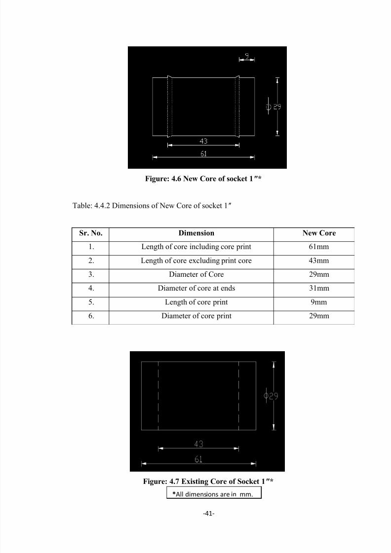
7/29/2019 Pipe Line Socket Thesis
http://slidepdf.com/reader/full/pipe-line-socket-thesis 52/81
-41-
Figure: 4.6 New Core of socket 1ʺ*
Table: 4.4.2 Dimensions of New Core of socket 1ʺ
Sr. No. Dimension New Core
1. Length of core including core print 61mm
2. Length of core excluding print core 43mm
3. Diameter of Core 29mm
4.
Diameter of core at ends 31mm5. Length of core print 9mm
6. Diameter of core print 29mm
Figure: 4.7 Existing Core of Socket 1ʺ**All dimensions are in mm.

7/29/2019 Pipe Line Socket Thesis
http://slidepdf.com/reader/full/pipe-line-socket-thesis 53/81
-42-
Table: 4.4.3 Dimensions of Existing Core of socket 1ʺ
Sr. No. Dimension Existing Core
1. Length of core excluding core print 43mm
2. Length of core including print core 61mm
3. Length of core print 9mm
4. Diameter of core 29mm
Figure: 4.8 Existing Core of Socket 1 ʺ*
Table: 4.4.4 Dimensions of Existing Core of socket 1 ʺ
Sr. No. Dimension Existing Core
1. Length of core excluding core print 50.5mm
2. Length of core including print core 70.5mm
3. Length of core print 10mm
4. Diameter of core 36.5mm
Figure: 4.9 New Core for socket 1 ʺ*
Table: 4.4.5 Dimensions of New Core of socket 1 ʺ
*All dimensions are in mm.

7/29/2019 Pipe Line Socket Thesis
http://slidepdf.com/reader/full/pipe-line-socket-thesis 54/81
-43-
Sr. No. Dimension New Core
1 Length of core including core print 70.5mm
2 Length of core excluding print core 50.5mm
3 Diameter of Core 36.5mm4 Diameter of core at ends 38.5mm
5 Length of core print 10mm
6. Diameter of core print 29mm
4.5 PROCEDURE FOR MAKING MOULDING SAND, MOULD
AND CASTING OF SOCKET:
None of the natural sand possesses the required qualities to the required extent. They
may lack in one or more of these properties which we have to make up by artificial
means to make the sand suitable for use. Sand mixing is the process through which we
add those materials to the sand which are rich in such characteristics which the sand
lacks. Sand to be used in moulding should be properly conditioned before use in order
to obtain good castings, since most of the defects which occur in castings are due to
improper conditioning of the sand. It holds good equally for the new as well as old or
used sand. Proper conditioning means the uniform distribution of the clay bond over the said grains, even distribution and proper control of the moisture content in the
sand and sorting out the foreign materials like nails, gaggers and other metal pieces
from the sand by ridding and a thorough mixing of the entire sand mass. Even today
above operation is carried out by hand in most of the small foundries. Since no testing
equipment is normally available in such foundries, the sand condition is judged by
moulders themselves by virtue of their practical experience only and the quality of the
castings produced in such foundries entirely depends upon this factor. A common
physical test, which is generally followed by most of, moulders, for judging the sand
condition is to grip a handful of the prepared foundry sand and then relieve the
pressure of the fingers. The sand mass thus produced is broken into two pieces by
hand and the edges formed at the broken section are carefully observed. If there is no
deformation in the edges the sand is supposed to properly conditioned. If the upper
surface of the broken pieces appears to be setting, down gradually, as if it is being
compressed, it indicates high moisture content. Gradual separation of sand grains, as
if they are being sprinkled from the parted surfaces, indicate a weak-bond and low
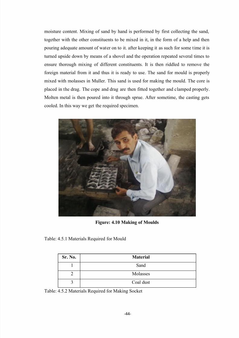
7/29/2019 Pipe Line Socket Thesis
http://slidepdf.com/reader/full/pipe-line-socket-thesis 55/81
-44-
moisture content. Mixing of sand by hand is performed by first collecting the sand,
together with the other constituents to be mixed in it, in the form of a help and then
pouring adequate amount of water on to it. after keeping it as such for some time it is
turned upside down by means of a shovel and the operation repeated several times to
ensure thorough mixing of different constituents. It is then riddled to remove the
foreign material from it and thus it is ready to use. The sand for mould is properly
mixed with molasses in Muller. This sand is used for making the mould. The core is
placed in the drag. The cope and drag are then fitted together and clamped properly.
Molten metal is then poured into it through sprue. After sometime, the casting gets
cooled. In this way we get the required specimen.
Figure: 4.10 Making of Moulds
Table: 4.5.1 Materials Required for Mould
Table: 4.5.2 Materials Required for Making Socket
Sr. No. Material
1 Sand
2 Molasses
3 Coal dust
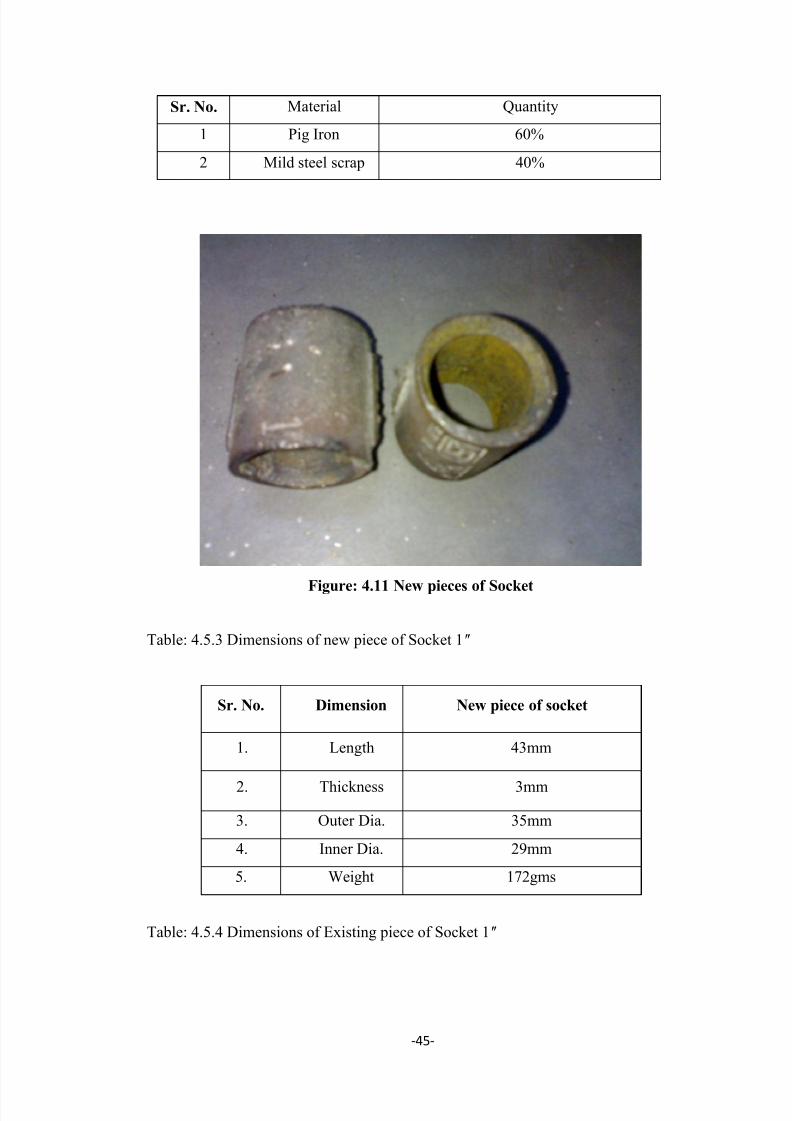
7/29/2019 Pipe Line Socket Thesis
http://slidepdf.com/reader/full/pipe-line-socket-thesis 56/81
-45-
Figure: 4.11 New pieces of Socket
Table: 4.5.3 Dimensions of new piece of Socket 1ʺ
Sr. No. Dimension New piece of socket
1. Length 43mm
2. Thickness 3mm
3. Outer Dia. 35mm
4. Inner Dia. 29mm
5. Weight 172gms
Table: 4.5.4 Dimensions of Existing piece of Socket 1ʺ
Sr. No. Material Quantity
1 Pig Iron 60%
2 Mild steel scrap 40%

7/29/2019 Pipe Line Socket Thesis
http://slidepdf.com/reader/full/pipe-line-socket-thesis 57/81
-46-
Sr. No. Dimension Existing piece of socket
1. Length 43mm
2. Thickness 3mm
3. Outer Dia. 35mm
4. Inner Dia. 29mm
5. Weight 180gms
Table: 4.5.5 Dimensions of New piece of Socket 1 ʺ
Sr. No. Dimension New piece of socket
1. Length 50.5mm
2. Thickness 3.5mm
3. Outer Dia. 43.5mm
4. Inner Dia. 36.5mm
5. Weight 274gms
Table: 4.5.6 Dimensions of Existing piece of Socket 1 ʺ
Sr. No. Dimension Existing piece of socket
1. Length 50.5mm
2. Thickness 3.5mm
3. Outer Dia. 43.5mm
4. Inner Dia. 36.5mm
5. Weight 286gms
4.6 TOOLS & EQUIPMENTS REQUIRED:

7/29/2019 Pipe Line Socket Thesis
http://slidepdf.com/reader/full/pipe-line-socket-thesis 58/81
-47-
Table: 4.6.1 Tools & Equipments Required
The function of various tools &equipments is explained as:
4.6.1 Shovel: It consists of iron pan with a wooden handle. It can be used for mixingand conditioning the sand and then transferring the mixture in some container.
Figure: 4.12 Shovel
Sr. No. Name of Tool/Equipment
1 Shovel2 Trowels
3 Lifters
4 Strike off bar
5 Vent wire
6 Draw spike
7 Licks
8 Sprue pin9 Sprue cutter
10 Bellows
11 Files
12 Moulding boxes
13 Ladle
14 Riddle
15 Muller 16 Furnace
17 Rotary blower
18 Weighing scale
19 Weights
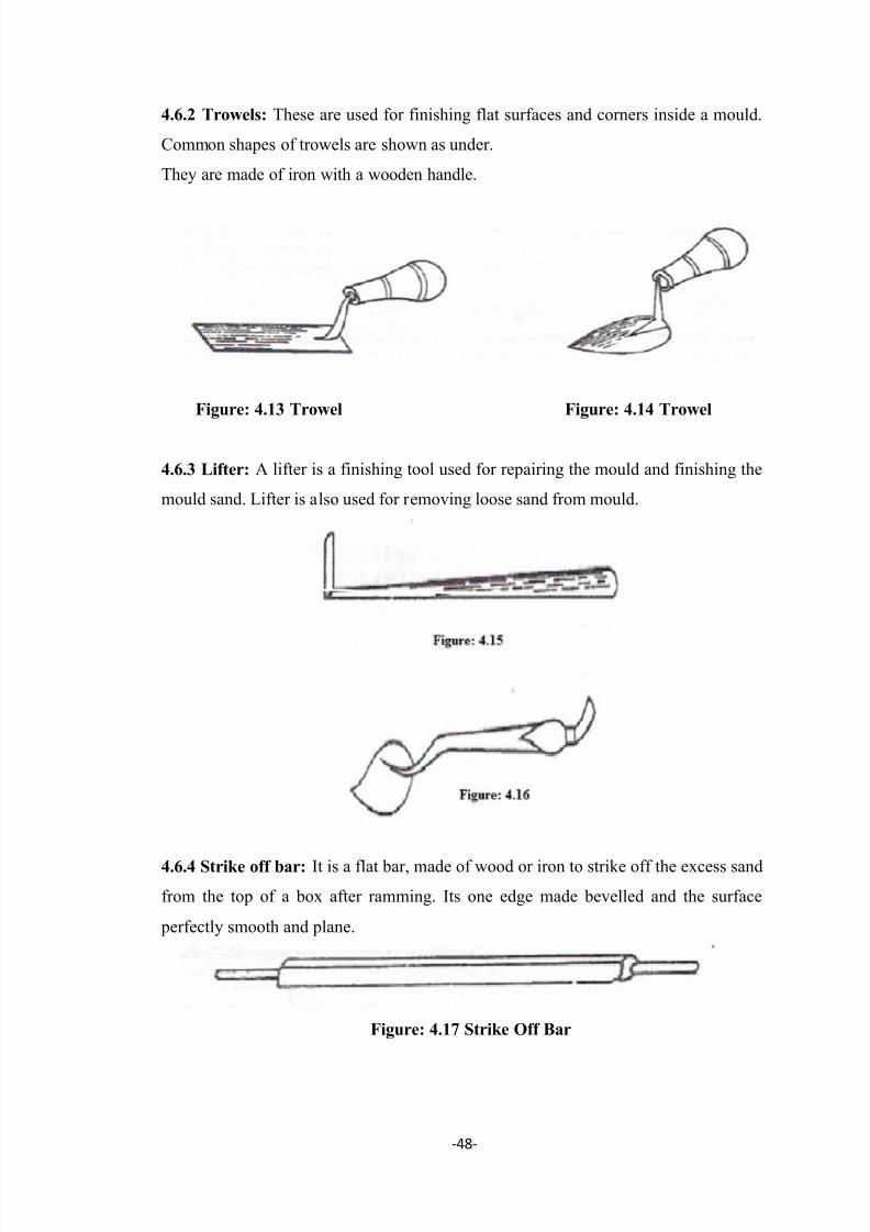
7/29/2019 Pipe Line Socket Thesis
http://slidepdf.com/reader/full/pipe-line-socket-thesis 59/81
-48-
4.6.2 Trowels: These are used for finishing flat surfaces and corners inside a mould.
Common shapes of trowels are shown as under.
They are made of iron with a wooden handle.
Figure: 4.13 Trowel Figure: 4.14 Trowel
4.6.3 Lifter: A lifter is a finishing tool used for repairing the mould and finishing the
mould sand. Lifter is also used for removing loose sand from mould.
4.6.4 Strike off bar: It is a flat bar, made of wood or iron to strike off the excess sand
from the top of a box after ramming. Its one edge made bevelled and the surface
perfectly smooth and plane.
Figure: 4.17 Strike Off Bar

7/29/2019 Pipe Line Socket Thesis
http://slidepdf.com/reader/full/pipe-line-socket-thesis 60/81
-49-
4.6.5 Vent wire: It is a thin steel rod or wire carrying pointed edge at one end and a
wooden handle or a bent loop at the other. After ramming and striking off the excess
sand it is used to make small holes, called vents, in the sand mould to allow the exit of
gases and steam during casting.
Figure: 4.18 Vent wire
4.6.6 Draw Spike: It is a tapered steel rod having a loop or ring at its one end and a
sharp point at the other. It is used to tap and draw patterns from the mould.
Figure: 4.19 Draw Spike
4.6.7 Slicks: They are used for repairing and finishing the mould surfaces and edges
after the pattern has been withdrawn. The commonly used slicks are heart and leaf,
square and heart, spoon and bead and heart and spoon.
Figure: 4.20 Slick
4.6.8 Sprue Pin: it is a tapered rod of wood or iron which is embedded in the sand
and later withdrawn to produce a hole, called runner, through which the molten metal
is poured into the mould.
4.6.9 Sprue Cutter: It is also used for the same purpose as a sprue pin but there is a
marked difference between their uses in that the cutter is used to produce the hole
after ramming the mould. It is in the form of a tapered hollow tube which is inserted
in the sand to produce the hole.
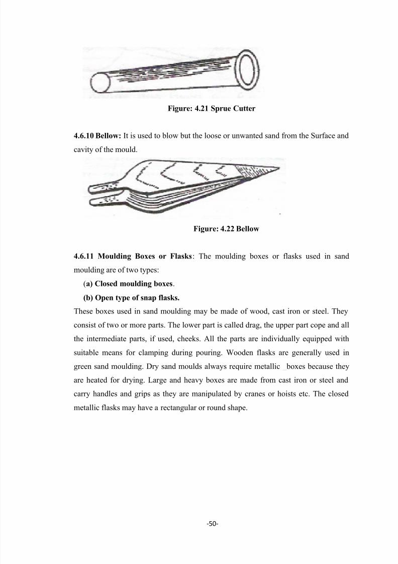
7/29/2019 Pipe Line Socket Thesis
http://slidepdf.com/reader/full/pipe-line-socket-thesis 61/81
-50-
Figure: 4.21 Sprue Cutter
4.6.10 Bellow: It is used to blow but the loose or unwanted sand from the Surface and
cavity of the mould.
Figure: 4.22 Bellow
4.6.11 Moulding Boxes or Flasks: The moulding boxes or flasks used in sand
moulding are of two types:
(a) Closed moulding boxes.
(b) Open type of snap flasks.
These boxes used in sand moulding may be made of wood, cast iron or steel. They
consist of two or more parts. The lower part is called drag, the upper part cope and all
the intermediate parts, if used, cheeks. All the parts are individually equipped with
suitable means for clamping during pouring. Wooden flasks are generally used in
green sand moulding. Dry sand moulds always require metallic _boxes because they
are heated for drying. Large and heavy boxes are made from cast iron or steel and
carry handles and grips as they are manipulated by cranes or hoists etc. The closed
metallic flasks may have a rectangular or round shape.
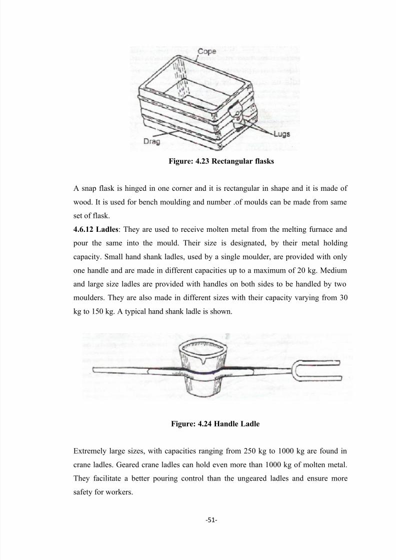
7/29/2019 Pipe Line Socket Thesis
http://slidepdf.com/reader/full/pipe-line-socket-thesis 62/81
-51-
Figure: 4.23 Rectangular flasks
A snap flask is hinged in one corner and it is rectangular in shape and it is made of
wood. It is used for bench moulding and number .of moulds can be made from same
set of flask.
4.6.12 Ladles: They are used to receive molten metal from the melting furnace and
pour the same into the mould. Their size is designated, by their metal holding
capacity. Small hand shank ladles, used by a single moulder, are provided with only
one handle and are made in different capacities up to a maximum of 20 kg. Medium
and large size ladles are provided with handles on both sides to be handled by two
moulders. They are also made in different sizes with their capacity varying from 30
kg to 150 kg. A typical hand shank ladle is shown.
Figure: 4.24 Handle Ladle
Extremely large sizes, with capacities ranging from 250 kg to 1000 kg are found in
crane ladles. Geared crane ladles can hold even more than 1000 kg of molten metal.
They facilitate a better pouring control than the ungeared ladles and ensure more
safety for workers.

7/29/2019 Pipe Line Socket Thesis
http://slidepdf.com/reader/full/pipe-line-socket-thesis 63/81
-52-
All the ladles, irrespective of their size, consist of an outer casing made of steel or
plate bent in proper shape and then welded. Inside this casing is provided a refractory
lining. At its top the casing is .shaped to have a controlled and well-directed flow of
molten metal.
Figure: 4.25 Handle Ladle
4.6.13 Muller
Figure: 4.26 Muller

7/29/2019 Pipe Line Socket Thesis
http://slidepdf.com/reader/full/pipe-line-socket-thesis 64/81
-53-
It is possible to mix foundry sand by hand, and quite successful moulds have been
made using this method for many generations, but the amateur foundry man will not
have the space or time to laboriously mix small quantities of sand to the quality that a
Muller can.
4.6.14 Rotary Furnace
Figure: 4.27 Rotary Furnace
The rotary melting furnace is the most flexible and universal design of equipment to
recycle aluminium scrap. Due to the nature of its operation all scrap forms can be
recycled with good results. The rotary furnace is rotated either by a friction drive
wheel system or a positive rack/pinion or chain drive depending upon the size and
production requirements. A single door is utilized with either vertical, horizontal
rotation or a pendulum type swing arrangement depending upon the plant layout. A
high efficiency fume extraction system is provided either fixed directly on the furnace
which tilts with the furnace and exhausts through a rotary joint or simply by a high
level fume collection hood / housing. Rotary furnaces have been traditionally static
but over recent years tilting designs have been implemented due to the many
advantages with regard to reduced cycle times, yields and consumptions. Mechatherm
engineer rotary furnaces to suit all applications and client requirements. We can
supply oxy-fuel burner system, cold air burner operating on either fuel oil or gas.

7/29/2019 Pipe Line Socket Thesis
http://slidepdf.com/reader/full/pipe-line-socket-thesis 65/81
-54-
CHAPTER: 5
RESULTS
1.
Reduction in Scrap Production for socket 1ʺ: - For calculating the reduction inscrap production due to chamfering, first the weights of sockets casted by using
existing and new core are noted. These two types of weights of sockets are
compared for calculating the reduction in scrap production. For this purpose, 25
sockets of each type are weighed and their weights are as given below:
Socket No. Weight of socket 1ʺ in gms.
with existing core
1 180
2 180
3 181
4 180
5 179
6 182
7 180
8 180
9 180
10 179
11 180
12 181
13 180
14 181
15 182
16 182
17 180
18 179
19 179
20 17921 179
22 179
23 179
24 179
25 180
Total weight of 25 sockets 4500
Weight per socket 180

7/29/2019 Pipe Line Socket Thesis
http://slidepdf.com/reader/full/pipe-line-socket-thesis 66/81
-55-
Difference in weight of one socket (with existing and new core) = 8gms
Reduction in scrap production = 8gms
% age of scrap reduction = 8 x 100/180
= 4.4%
Socket No. Weight of socket 1ʺ in gms.
with new core
1 1722 172
3 172
4 172
5 173
6 173
7 172
8 172
9 172
10 172
11 172
12 171
13 172
14 172
15 172
16 173
17 173
18 173
19 171
20 171
21 171
22 17223 171
24 172
25 172
Total weight of 25 sockets. 3300
Weight per socket 172

7/29/2019 Pipe Line Socket Thesis
http://slidepdf.com/reader/full/pipe-line-socket-thesis 67/81
-56-
2. Reduction in Scrap Production for socket 1 ˝ : - Reduction in scrap production
is calculated in the same manner which has been used previously in case of socket
1ʺ and is explained as below:
Socket No. Weight of socket 1 ʺ in gms.
With existing core
1 286
2 286
3 286
4 2865 286
6 288
7 286
8 286
9 287
10 286
11 286
12 286
13 286
14 28615 286
16 287
17 287
18 286
19 286
20 285
21 285
22 284
23 286
24 285
25 286
Total weight of 25 sockets 7150
Weight per socket 286

7/29/2019 Pipe Line Socket Thesis
http://slidepdf.com/reader/full/pipe-line-socket-thesis 68/81
-57-
Socket No Weight of socket 1 ʺ in gms
with new core
1 274
2 274
3 274
4 274
5 274
6 274
7 274
8 274
9 275
10 275
11 274
12 27413 274
14 274
15 274
16 274
17 274
18 274
19 275
20 274
21 274
22 27223 274
24 273
25 274
Total weight of 25 sockets 6850
Weight per socket 274
Difference in weight of one socket (reduction in scrap) = 12gms
Reduction in scrap production = 12gms
% age of scrap reduction = 12 x 100/286
= 4.2%
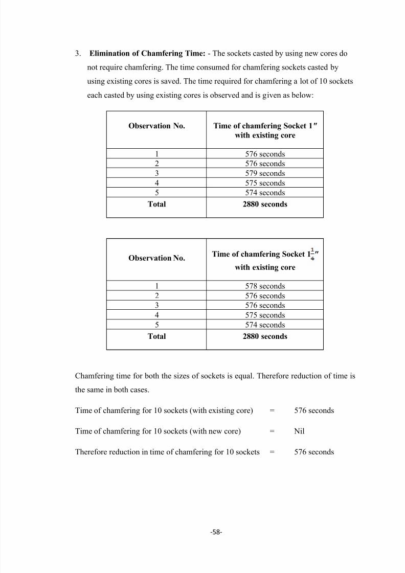
7/29/2019 Pipe Line Socket Thesis
http://slidepdf.com/reader/full/pipe-line-socket-thesis 69/81
-58-
3. Elimination of Chamfering Time: - The sockets casted by using new cores do
not require chamfering. The time consumed for chamfering sockets casted by
using existing cores is saved. The time required for chamfering a lot of 10 sockets
each casted by using existing cores is observed and is given as below:
Observation No. Time of chamfering Socket 1ʺ
with existing core
1 576 seconds
2 576 seconds
3 579 seconds
4 575 seconds
5 574 seconds
Total 2880 seconds
Observation No.Time of chamfering Socket 1 ʺ
with existing core
1 578 seconds
2 576 seconds
3 576 seconds
4 575 seconds
5 574 seconds
Total 2880 seconds
Chamfering time for both the sizes of sockets is equal. Therefore reduction of time is
the same in both cases.
Time of chamfering for 10 sockets (with existing core) = 576 seconds
Time of chamfering for 10 sockets (with new core) = Nil
Therefore reduction in time of chamfering for 10 sockets = 576 seconds
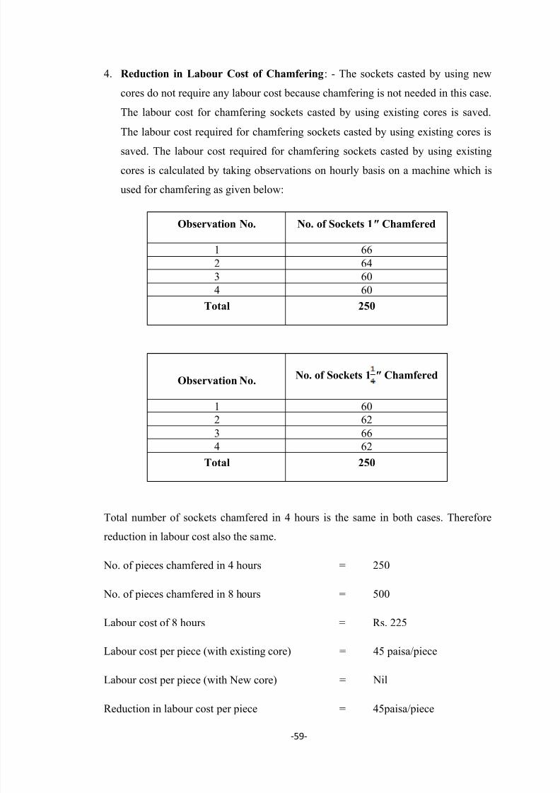
7/29/2019 Pipe Line Socket Thesis
http://slidepdf.com/reader/full/pipe-line-socket-thesis 70/81
-59-
4. Reduction in Labour Cost of Chamfering: - The sockets casted by using new
cores do not require any labour cost because chamfering is not needed in this case.
The labour cost for chamfering sockets casted by using existing cores is saved.
The labour cost required for chamfering sockets casted by using existing cores is
saved. The labour cost required for chamfering sockets casted by using existing
cores is calculated by taking observations on hourly basis on a machine which is
used for chamfering as given below:
Observation No. No. of Sockets 1ʺ Chamfered
1 66
2 64
3 604 60
Total 250
Observation No.No. of Sockets 1 ʺ Chamfered
1 60
2 623 66
4 62
Total 250
Total number of sockets chamfered in 4 hours is the same in both cases. Therefore
reduction in labour cost also the same.
No. of pieces chamfered in 4 hours = 250
No. of pieces chamfered in 8 hours = 500
Labour cost of 8 hours = Rs. 225
Labour cost per piece (with existing core) = 45 paisa/piece
Labour cost per piece (with New core) = Nil
Reduction in labour cost per piece = 45paisa/piece

7/29/2019 Pipe Line Socket Thesis
http://slidepdf.com/reader/full/pipe-line-socket-thesis 71/81
-60-
5. Reduction in Cutting Tool Cost for Chamfering: - The sockets casted by using
new cores do not require chamfering. Therefore there is no cutting cost for
chamfering in this case. The cutting tool cost for chamfering sockets casted by
using existing cores is saved. The cutting tool cost required for chamfering
sockets casted by using existing cores is calculated as given below:
For Socket 1ʺ
No. of cutting bits used = 3
Cost of 3 cutting bits = Rs. 360
No. of sockets chamfered (with existing core) = 5000
Cost of chamfering of sockets (with existing core) = 360 X 100/5000
= 7.2 paisa/socket
Cost of chamfering (with new core) = Nil
Reduction in expenses on cutting tool = 7.2 paisa/socket
For Socket 1 ʺ
No. of cutting bits used = 3
Cost of 3 cutting bits = Rs. 360
No. of sockets chamfered (with existing core) = 5000
Cost of chamfering of sockets (with existing core) = 360 X 100/5000
= 7.2 paisa/socket
No. of sockets chamfered (with existing core) = 5000
Cost of chamfering (with new core) = Nil
Reduction in expenses on cutting tool = 7.2 paisa/socket
Cutting tool cost of chamfering for both the sizes of socket is equal. Therefore
reduction in cutting tool cost is the same in both cases.
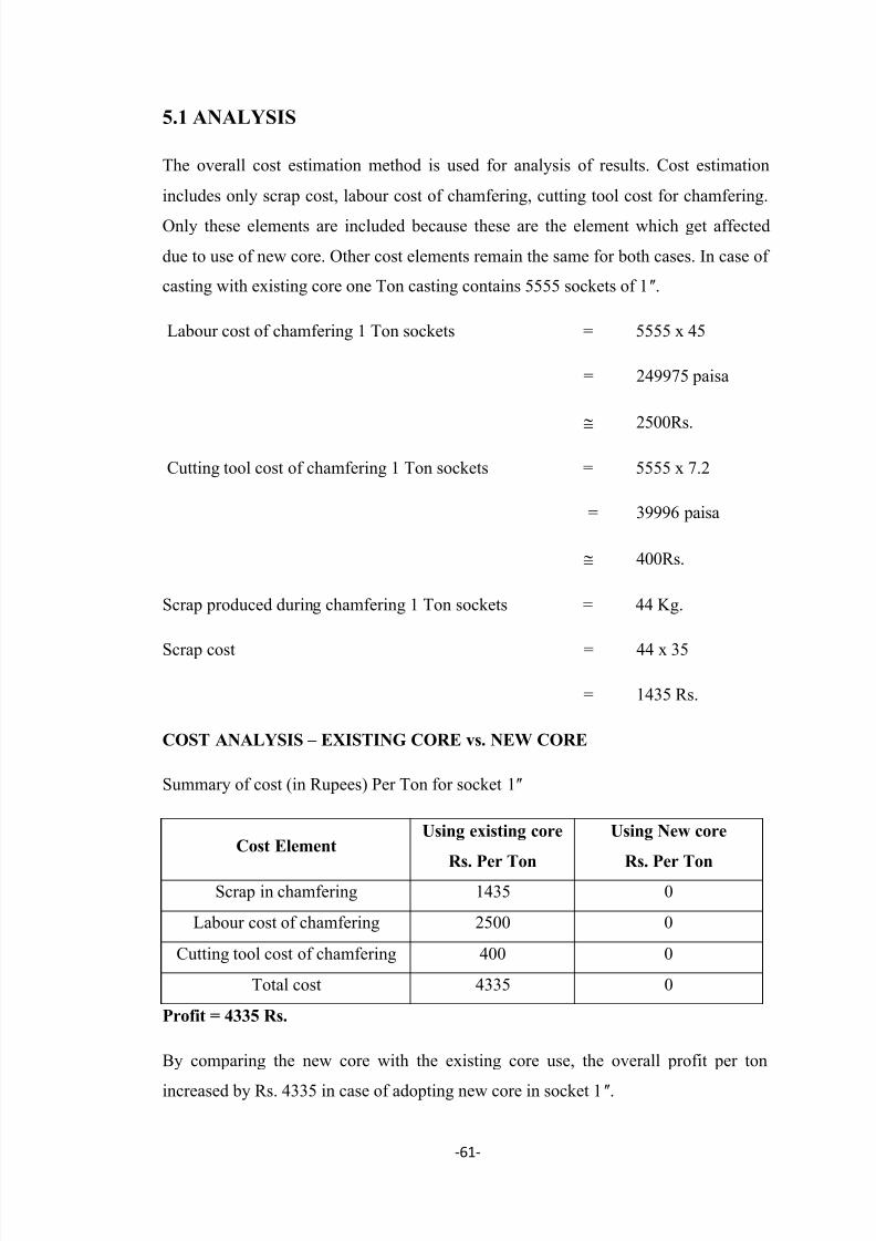
7/29/2019 Pipe Line Socket Thesis
http://slidepdf.com/reader/full/pipe-line-socket-thesis 72/81
-61-
5.1 ANALYSIS
The overall cost estimation method is used for analysis of results. Cost estimation
includes only scrap cost, labour cost of chamfering, cutting tool cost for chamfering.
Only these elements are included because these are the element which get affected
due to use of new core. Other cost elements remain the same for both cases. In case of
casting with existing core one Ton casting contains 5555 sockets of 1ʺ.
Labour cost of chamfering 1 Ton sockets = 5555 x 45
= 249975 paisa
2500Rs.
Cutting tool cost of chamfering 1 Ton sockets = 5555 x 7.2
= 39996 paisa
400Rs.
Scrap produced during chamfering 1 Ton sockets = 44 Kg.
Scrap cost = 44 x 35
= 1435 Rs.
COST ANALYSIS – EXISTING CORE vs. NEW CORE
Summary of cost (in Rupees) Per Ton for socket 1ʺ
Cost ElementUsing existing core
Rs. Per Ton
Using New core
Rs. Per TonScrap in chamfering 1435 0
Labour cost of chamfering 2500 0
Cutting tool cost of chamfering 400 0
Total cost 4335 0
Profit = 4335 Rs.
By comparing the new core with the existing core use, the overall profit per ton
increased by Rs. 4335 in case of adopting new core in socket 1ʺ.

7/29/2019 Pipe Line Socket Thesis
http://slidepdf.com/reader/full/pipe-line-socket-thesis 73/81
-62-
In case of casting with existing core one Ton casting contains 3496 sockets 1 ʺ
Labour cost of chamfering 1 Ton sockets = 3496 x 45
= 157320 paisa
1573Rs.
Cutting tool cost of chamfering 1 Ton sockets = 3496 x 7.2
= 25171.2 paisa
251Rs.
Scrap produced during chamfering 1 Ton sockets = 42 Kg.
Scrap cost = 42 x 35
= 1470 Rs.
Summary of cost (in Rupees) Per Ton for socket 1 ʺ
Cost ElementUsing existing core
Rs. Per Ton
Using New core
Rs. Per Ton
Scrap in chamfering 1470 0
Labour cost of chamfering 1573 0
Cutting tool cost of
chamfering251 0
Total cost 3294 0
Profit = 3294 Rs.
By comparing the new core with the existing core use, the overall profit per ton
increased by Rs. 3294 in case of adopting new core in socket 1 ʺ.
So it shows the advantages of using new cores.

7/29/2019 Pipe Line Socket Thesis
http://slidepdf.com/reader/full/pipe-line-socket-thesis 74/81
-63-
5.2 DISCUSSION
Scrap Production :- Experiments carried out with new shaped core show that scrap
due to chamfering is not produced using these cores because chamfering is not needed
in this case whereas scrap produced due to chamfering increases with an increase in
number of pieces in case of using existing core. The variation in scrap production
with existing and new core for socket 1ʺ is shown graphically as:
0
100
200
300400
500
600
700
800
900
10 20 30 40 50 60 70 80 90 100
Pieces with existing
core
Pieces with new shapedcore
Number of Pieces
Graph 1- Plot of scrap production during chamfering for pieces with existing and
new core for socket 1ʺ
0
1000
2000
3000
4000
5000
6000
7000
8000
10 20 30 40
Pieces with existing core
Pieces with new shaped
core
Graph 2- Bar graph showing weight of socket 1ʺ with existing and new shaped core
S c r a W e i h t i n G m s .
No. Of Pieces
W e i h t i n
m s .

7/29/2019 Pipe Line Socket Thesis
http://slidepdf.com/reader/full/pipe-line-socket-thesis 75/81
-64-
0
200
400
600
800
1000
1200
1400
10 20 30 40 50 60 70 80 90 100
Pieces with existing core
pieces with new shaped
core
Graph 3- Plot of scrap production during chamfering for pieces with existing and
new core for socket 1 ʺ
0
2000
4000
6000
8000
10000
12000
10 20 30 40
Pieces with existing core
Pieces with new shaped core
Graph 4- Bar graph showing weight of socket 1 ʺ.with existing and new shaped core.
W e i g h t i n g m s .
No. Of Pieces
S c r a W e i h t i n G m s .
No. Of Pieces

7/29/2019 Pipe Line Socket Thesis
http://slidepdf.com/reader/full/pipe-line-socket-thesis 76/81
-65-
Labour Cost of Chamfering :- Our experiments have shown that there is no labour
cost of chamfering using new core. With existing core labour cost is 45 paisa/piece.
The variation in labour cost of chamfering for existing and new core products is
shown graphically as:
0
100
200
300
400
500
100 200 300 400 500 600 700 800 900 1000
Pieces with existing
core
Pieces with new shaped
core
Number of Pieces
Graph 5- Plot showing labour cost of chamfering for pieces with existing and new
core for sockets 1ʺ and 1 ʺ.
0
50
100
150
200
250
300
350
400
200 400 600 800
Pieces with existing core
Pieces with new shaped
core
Graph 6 – Bar graph showing labour cost of chamfering for pieces with existing and
new core for sockets 1ʺ and 1 ʺ.
L a b o u r c o s t i n R s .
L a b o u r c o s t i n R s .
No. Of Pieces

7/29/2019 Pipe Line Socket Thesis
http://slidepdf.com/reader/full/pipe-line-socket-thesis 77/81
-66-
Cutting Tool Cost of Chamfering :- Our experiments have shown that there is no
cutting tool cost of chamfering using new core. With existing core cutting tool cost is
7.2 paisa/piece. The variation in cutting tool cost of chamfering for existing and new
core products is shown graphically as:
0
50
100
150
200
250
300
350
400
1000 2000 3000 4000 5000
Pieces with existing core
Pieces with new shaped
core
Number of Pieces
Graph 7 – Plot showing cutting tool cost during chamfering for pieces with existing
and new core for sockets 1ʺ and 1 ʺ
0
50100
150
200
250
300
350
400
1250 2500 3750 5000
pieces with existing
core
pieces with new core
Number of Pieces
Graph 8 – Bar graph showing cutting tool cost during chamfering for pieces with
existing and new core for sockets 1ʺ and 1 ʺ.
C u t t i n t o o l c o s t i n R s .
C u t t i n t o o l c o s t i n R s .

7/29/2019 Pipe Line Socket Thesis
http://slidepdf.com/reader/full/pipe-line-socket-thesis 78/81
-67-
Time of Chamfering :- Our experiments have shown that no time is needed for
chamfering using new core. With existing core time consumed is 576 seconds for 10
pieces. The variation in time of chamfering for existing and new core products is
shown graphically as:
0
1000
2000
3000
4000
5000
6000
7000
10 20 30 40 50 60 70 80 90 100
Pieces with existing
core
Pieces with new
shaped core
Number of Pieces
Graph 9 – Plot showing time of chamfering for pieces with existing and new core for
sockets 1ʺ and 1 ʺ.
0
50
100
150
200
250
300
350
400
1250 2500 3750 5000
Pieces with existing core
Pieces with new shaped
core
Number of pieces
Graph 10 – Bar graph showing time of chamfering for pieces with existing and new
core for sockets 1ʺ and 1 ʺ.
T i m e o f c h a m f e r i n g i n s e c o n d s
T i m e o f
c h a m f e r i n g i n s e c o n d s
7/29/2019 Pipe Line Socket Thesis
http://slidepdf.com/reader/full/pipe-line-socket-thesis 79/81
-68-
CHAPTER: 6
CONCLUSION
1) Experiments have shown that no scrap is produced due to chamfering in case of using new core. It is because chamfering is not needed in this case. Scrap produced
during chamfering in case of existing core with socket 1˝ is 8 gm. per piece. Hence in
case of metal casting of 2 tonnes there is saving of 88 kilogram of scrap. The market
cost of scrap is about Rs. 22 per kilogram, whereas the cost of malleable casting is Rs.
62 per kilogram. Hence there can be saving Rs. 3520 in that case. In case of socket
1 ʺ, there is saving of 12 gm per piece.
2) No time is needed for chamfering in case of using new core whereas time of
chamfering n case of using existing core is 576 seconds for 10 pieces.
3) There is no cutting tool cost in case of using new core. In case of using existing
core, the cost of cutting tools for chamfering is Rs. 360 for 5000 pieces.
4) There is no labour cost for chamfering in case of using new core. In case of using
existing core the labour cost is 45 paisa per piece.
The productivity has improved with the use of new shaped core due to
reduction in scrap production, time needed for chamfering, cutting tool cost and
labour cost for chamfering.
6.1 SCOPE OF IMPROVEMENT
The chamfering work is needed in all other pipe fittings including Tee, Elbow and
Union of different sizes. There is scope of eliminating the need for chamfering these
items also. New shaped cores for these items need to be developed. Productivity of
pipe fitting industry will improve to great extent by using such cores.

7/29/2019 Pipe Line Socket Thesis
http://slidepdf.com/reader/full/pipe-line-socket-thesis 80/81
-69-
REFERENCES
1. C. Li and B.G. Thomas 2000, “Analysis of the potential productivity of continues
cast moulds.” pp. 595-611
2. Thomas Schroeder 2004, “Starch and dextrin based adhesives.”
3. Nicolas Perry, Magali Mauchand, Alain Bernard 2004, “Costs models in design
and manufacturing of sand castings products.” IDMME.
4. L.A. Dobrazański, M. Krupiński, J.H. Sokolowski, P. Zarychta and Wlodarczyk -
Fligier 2006, “Methodology of analysis of casting defects” Journal of
Achievements in materials and manufacturing engineering, Vol. 18 Issue 1-2
5.
J. Dańko, M. Holtzer, R. Dańko 2007, “Factors influencing selection of effectivereclamation techniques and assessment methods of the reclaimed material
quality.” Archives Of Foundry Engineering, ISSN (1897-3310) Vol. 7, pp. 29-32
6. A. Fedoryszyn 2007, "Assessment of systems for mechanisation of casting
production.”, Archives of Foundry Engineering, Vol. 7 pp. 83-86
7. F. Peters, R. Voigt, S.Z. Ou and C. Beckermann 2007,“Effect of mould expansion
on pattern allowances nib sand casting of steel”, International Journal of Cast
Metals Research , Vol.20 No. 5
8. Liu Weihua, Li Yingamin, Qu Xueliang, Liu Xiuling 2008,“Study on binder
system of CO2-cured phenol-formaldehyde resin used in foundry”, China
Foundry, Vol. 5 No. 2
9. E.O. Olakanmi and A.O. Arome 2009, “Characterisation of the core-binding
properties of fatty based oils”, International Journal of Physical Sciences, Vol.
4(11), pp. 623-628
10. Slavomír Peľák, Rudolf Mišičko, Dagmar Fedáková, Jana Bidulská 2009,
“Between the dendrite structure quality, the casting technology and the defects in
continuously cast slabs.” Materials Engineering, Vol. 16 No. 4
11. A.K.M.B. Rashid 2010, “Casting defects.” Advanced Topics in Foundry
Engineering
12. Lakashamanan Singaram 2010, “Improving quality of sand casting using Taguchi
method and Ann analysis.” International Journal on Design and Manufacturing
Technologies, Vol. 4 No. 1

7/29/2019 Pipe Line Socket Thesis
http://slidepdf.com/reader/full/pipe-line-socket-thesis 81/81
13. R. Venkataraman 2010, “Innovative ideas for improving foundry productivity and
casting quality.” Transactions of 58th IFC
14. Nishikant M Ejrekar, Vicky Kapur 2011, “Refractory coating – A Practical
A pproach.” Foundry, Vol. 23 No. 1
15. Anil Barik, “Effects and controlling measures of directional solidification in
castings towards quality improvement.”, foundry Journal, Vol. 23 No. 5
16. Q.S.I. Fayomi, O.O. Ajayi and A.P.I. Popoola 2011,“Suitability of local binder
compositional variation on silica sand for foundry core-making”, International
Journal of Physical Sciences, Vol. 6(8), pp. 1940-1946
17. J.S. Colton 2011, “Casting defects & design issues.” Manufacturing Processes and
Systems
18. R. Vinayagasundaram, V.R. Nedunchezhian 2012, “Application OF Modern
Technology in Foundry and its Impact on Productivity and Profitability”,
European Journal of Social Sciences, Vol. 29, pp. 320-330
19. Bharathi Rajkumar K. and Gukan Rajaram 2012, “Productivity enhancement in
foundry industry using lean tools.” Indian Foundry Journal, Vol. 58, No. 9
20. Norberto T. Rizzo Downes, Ramon D. Duque, “Ten steps to improving casting
yield in ductile iron foundries.”
21. IS: 4759-1979, Indian Standard Specification for Hot-Dip Zinc Coatings on
Structural Steel and Other Allied Products.
22. IS: 2108-1977, Indian Standard Specification for Black Heart Malleable Iron
Castings.
23. IS: 2107-1977, Indian Standard Specification for White Heart Malleable Iron
Castings.
24. IS: 2633-1972, Method for Testing Indian Standard Uniformity of Coating on
Zinc Coated Articles.
25. IS: 6745-1972, Indian Standard Method for Testing Mass of Coating on Zinc
Related Documents


