PIP II SRF Program Slava Yakovlev DOE Independent Project Review of PIP-II 16 June 2015

Welcome message from author
This document is posted to help you gain knowledge. Please leave a comment to let me know what you think about it! Share it to your friends and learn new things together.
Transcript
PIP II SRF Program
Slava YakovlevDOE Independent Project Review of PIP-II16 June 2015
Outline
• The linac reference design; • The main challenges and technical risks; • Relevant R&D; • The reference design of critical components; • Status of RF and mechanical design of CMs; • TD organization, staffing and facilities;• LCLS II activity;• Summary
6/9/15Slava Yakovlev | PIP II SRF Program2
PIP II SC Linac Requirements
6/9/15Slava Yakovlev | PIP II SRF Program3
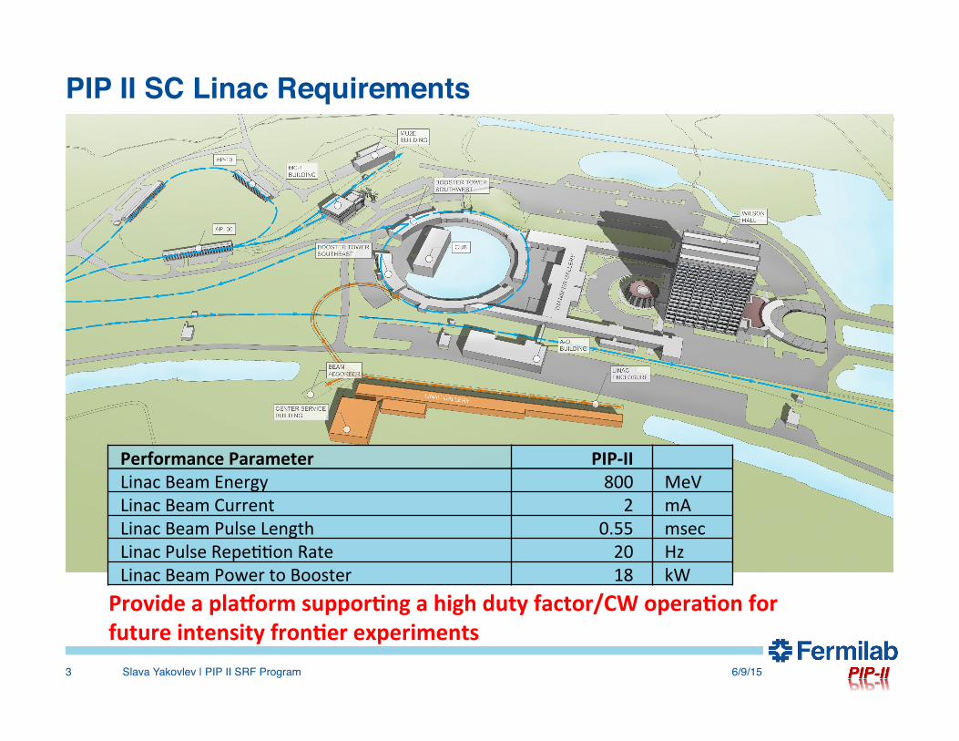
Performance Parameter PIP-‐II Linac Beam Energy 800 MeV Linac Beam Current 2 mA Linac Beam Pulse Length 0.55 msec Linac Pulse Repe??on Rate 20 Hz Linac Beam Power to Booster 18 kW Provide a pla3orm suppor6ng a high duty factor/CW opera6on for future intensity fron6er experiments

The Linac Reference Design • The reference design is ready:• Frequency choice: sub-harmonics of 1.3 GHz
- 162.5 MHz, 325 MHz and 650 MHz;• RF cavity types and betas:
- one section of 162.5 MHz HWR type, β = 0.11 cavity, - two sections of 325 MHz spoke-cavity type, SSR1 and SSR2 with
β = 0.22 and β = 0.47; and - two sections of elliptical 650 MHz cavities with β = 0.61 and β = 0.92;
• Break points are optimized in order to minimize the number of the cavities;• CM concept:
- separate CMs, - solenoids for HWR and SSR, - no focusing elements for elliptical.
• Operating regimes – both pulsed and CW;• No HOM dampers.
6/9/15Slava Yakovlev | PIP II SRF Program4

The Linac Reference Design
6/9/15Slava Yakovlev | PIP II SRF Program5
Section Freq Energy (MeV) Cav/mag/CM Type RFQ 162.5 0.03-2.1
HWR (βopt=0.11) 162.5 2.1-10.3 8/8/1 HWR, solenoid
SSR1 (βopt=0.22) 325 10.3-35 16/8/ 2 SSR, solenoid
SSR2 (βopt=0.47) 325 35-185 35/21/7 SSR, solenoid
LB 650 (βg=0.61) 650 185-500 33/22/11 5-cell elliptical, doublet*
HB 650 (βg=0.92) 650 500-800 24/8/4 5-cell elliptical, doublet*
*Warm doublets external to cryomodules All components CW-capable
The Linac Reference Design
6/9/15Slava Yakovlev | PIP II SRF Program6
Name β Freq (MHz)
Type of cavity
Bpeak (mT)
Epeak (MV/m)
Eacc (MV/m)
ΔE
(MeV)
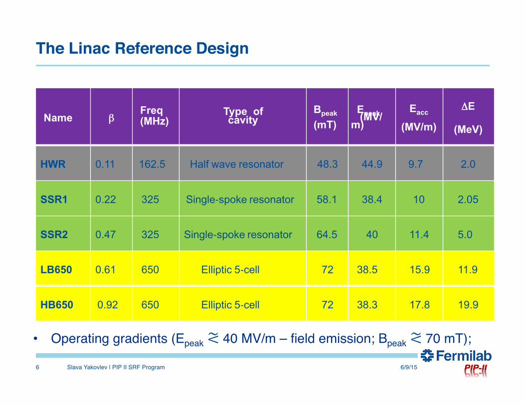
HWR 0.11 162.5 Half wave resonator 48.3 44.9 9.7 2.0
SSR1 0.22 325 Single-‐spoke resonator 58.1 38.4 10 2.05
SSR2 0.47 325 Single-‐spoke resonator 64.5 40 11.4 5.0
LB650 0.61 650 Elliptic 5-‐cell 72 38.5 15.9 11.9
HB650 0.92 650 Elliptic 5-‐cell 72 38.3 17.8 19.9
• Operating gradients (Epeak ⪝ 40 MV/m – field emission; Bpeak ⪝ 70 mT);
The main challenges and technical risks
6/9/15Slava Yakovlev | PIP II SRF Program7
• Future CW operation → cryo-losses → high Q0 is desired;
• Low beam loading → narrow bandwidth;– Pulsed regime → Lorentz Force Detune (LFD);– CW regime → microphonics;
• High-Order Modes → “to damp, or not to damp?”
R&D approach:
• High-Q0 program was initiated and is running successfully;• Resonance Control program is underway in order to mitigate
both microphonics and LFD;• “Passive” mitigation of the cavity detune – improvement of
cavity mechanical properties is underway;• Detailed HOM analysis is performed.
6/9/15Slava Yakovlev | PIP II SRF Program8
High Q0 R&D program
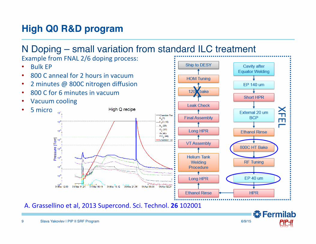
N Doping – small variation from standard ILC treatment
6/9/15Slava Yakovlev | PIP II SRF Program9
Example from FNAL 2/6 doping process: • Bulk EP • 800 C anneal for 2 hours in vacuum • 2 minutes @ 800C nitrogen diffusion • 800 C for 6 minutes in vacuum • Vacuum cooling • 5 microns EP
A. Grassellino et al, 2013 Supercond. Sci. Technol. 26 102001
High Q0 R&D program
6/9/15Slava Yakovlev | PIP II SRF Program10
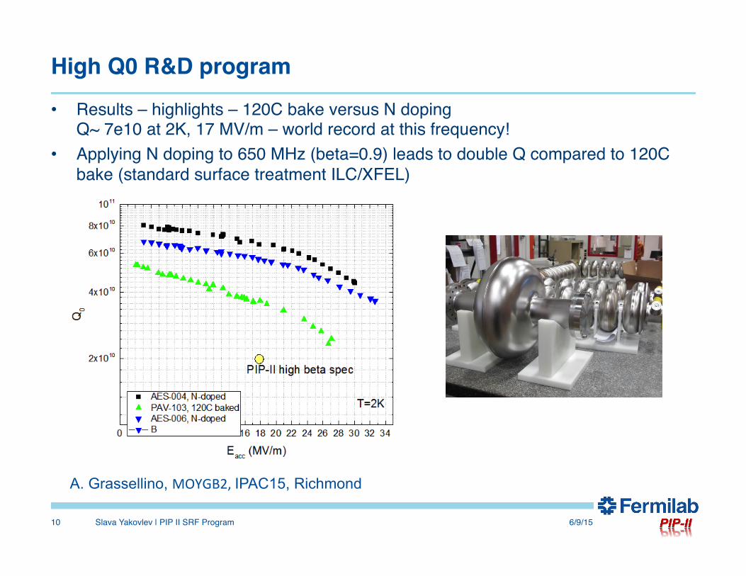
• Results – highlights – 120C bake versus N doping Q~ 7e10 at 2K, 17 MV/m – world record at this frequency!
• Applying N doping to 650 MHz (beta=0.9) leads to double Q compared to 120C bake (standard surface treatment ILC/XFEL)
A. Grassellino, MOYGB2, IPAC15, Richmond
High Q0 R&D program
6/9/15Slava Yakovlev | PIP II SRF Program11
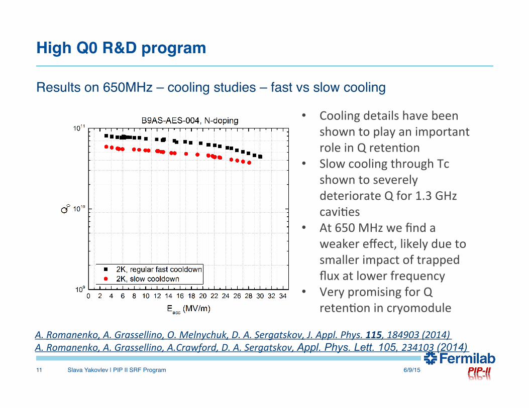
Results on 650MHz – cooling studies – fast vs slow cooling
• Cooling details have been shown to play an important role in Q reten?on
• Slow cooling through Tc shown to severely deteriorate Q for 1.3 GHz cavi?es
• At 650 MHz we find a weaker effect, likely due to smaller impact of trapped flux at lower frequency
• Very promising for Q reten?on in cryomodule
A. Romanenko, A. Grassellino, O. Melnychuk, D. A. Sergatskov, J. Appl. Phys. 115, 184903 (2014) A. Romanenko, A. Grassellino, A.Crawford, D. A. Sergatskov, Appl. Phys. Lett. 105, 234103 (2014)
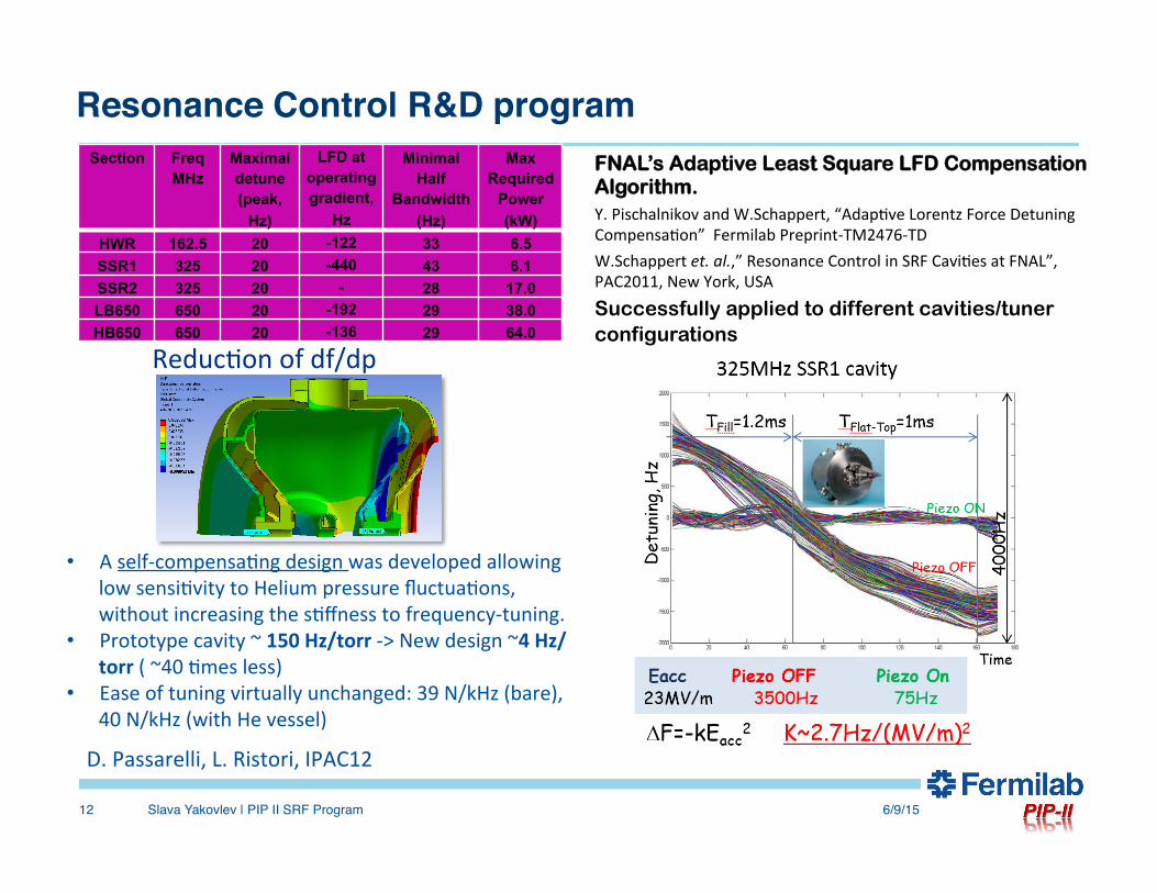
Resonance Control R&D programSection Freq
MHz Maximal detune (peak,
Hz)
LFD at operating gradient,
Hz
Minimal Half
Bandwidth (Hz)
Max Required
Power (kW)
HWR 162.5 20 -122 33 6.5 SSR1 325 20 -440 43 6.1 SSR2 325 20 - 28 17.0 LB650 650 20 -192 29 38.0 HB650 650 20 -136 29 64.0
6/9/15Slava Yakovlev | PIP II SRF Program12
Reduc?on of df/dp
D. Passarelli, L. Ristori, IPAC12
• A self-‐compensa?ng design was developed allowing low sensi?vity to Helium pressure fluctua?ons, without increasing the s?ffness to frequency-‐tuning.
• Prototype cavity ~ 150 Hz/torr -‐> New design ~4 Hz/torr ( ~40 ?mes less)
• Ease of tuning virtually unchanged: 39 N/kHz (bare), 40 N/kHz (with He vessel)
FNAL’s Adaptive Least Square LFD Compensation Algorithm. Y. Pischalnikov and W.Schappert, “Adap?ve Lorentz Force Detuning Compensa?on” Fermilab Preprint-‐TM2476-‐TD W.Schappert et. al.,” Resonance Control in SRF Cavi?es at FNAL”, PAC2011, New York, USA
Successfully applied to different cavities/tuner configurations
Resonance Control R&D program
6/9/15Slava Yakovlev | PIP II SRF Program13
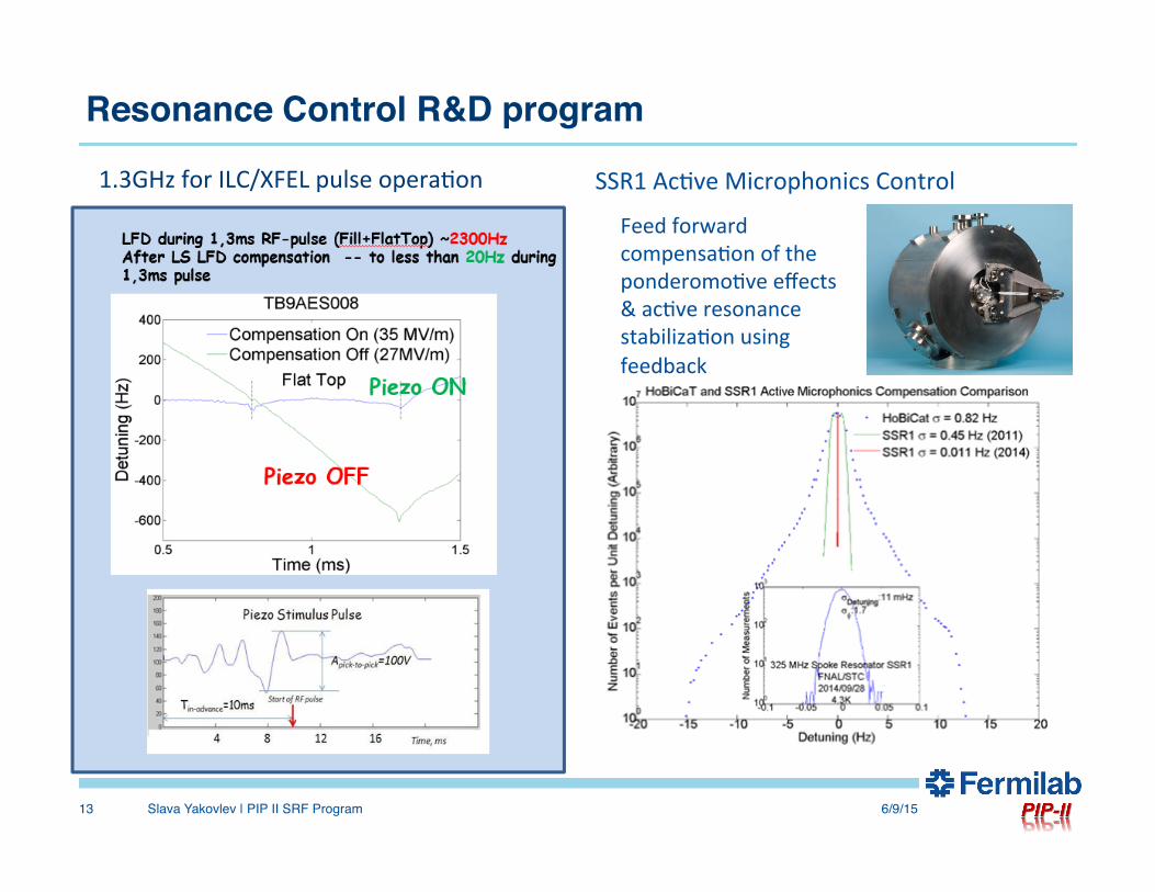
1.3GHz for ILC/XFEL pulse opera?on
Feed forward compensa?on of the ponderomo?ve effects & ac?ve resonance stabiliza?on using feedback
SSR1 Ac?ve Microphonics Control

Studies of HOMs in the PIP II
6/9/15Slava Yakovlev | PIP II SRF Program14
o Small beam current o Small bunch population Detailed simulations show:
• Beam Break Up (BBU) should not be a problem;
• “Klystron-type” longitudinal instability does not look to be a problem as well.
• Resonance excitation of the dipole modes does not look to be an issue;
• Accidental resonance excitation of the 2d monopole band in beta=0.9 section may lead to longitudinal emittance dilution, but probability is very small. However, v.2 of the cavity was designed which is free of this issue.
No HOM dampers for PIP II
General design approach
• Most components (couplers, tuners, etc.) should be of the same or similar type;
• Cryomodules should be preferably of the same type and contain mostly the same parts;
• Two types of CMs are to be prototyped, - spoke-cavity CM for SSR1 and - elliptical cavity CM for HB 650.
• Other CMs will be developed basing on the lessons learned for these CMs.
6/9/15Slava Yakovlev | PIP II SRF Program15
Status of development of critical components
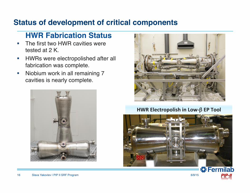
§ The first two HWR cavities were tested at 2 K.
§ HWRs were electropolished after all fabrication was complete.
§ Niobium work in all remaining 7 cavities is nearly complete.
6/9/15Slava Yakovlev | PIP II SRF Program16
HWR Fabrication Status
HWR Electropolish in Low-‐β EP Tool

Status of development of critical components
6/9/15Slava Yakovlev | PIP II SRF Program17
• HWR Cryomodule Vessel Assembly
Titanium Strongback
Cryostat vessel in factory
Status of development of critical components
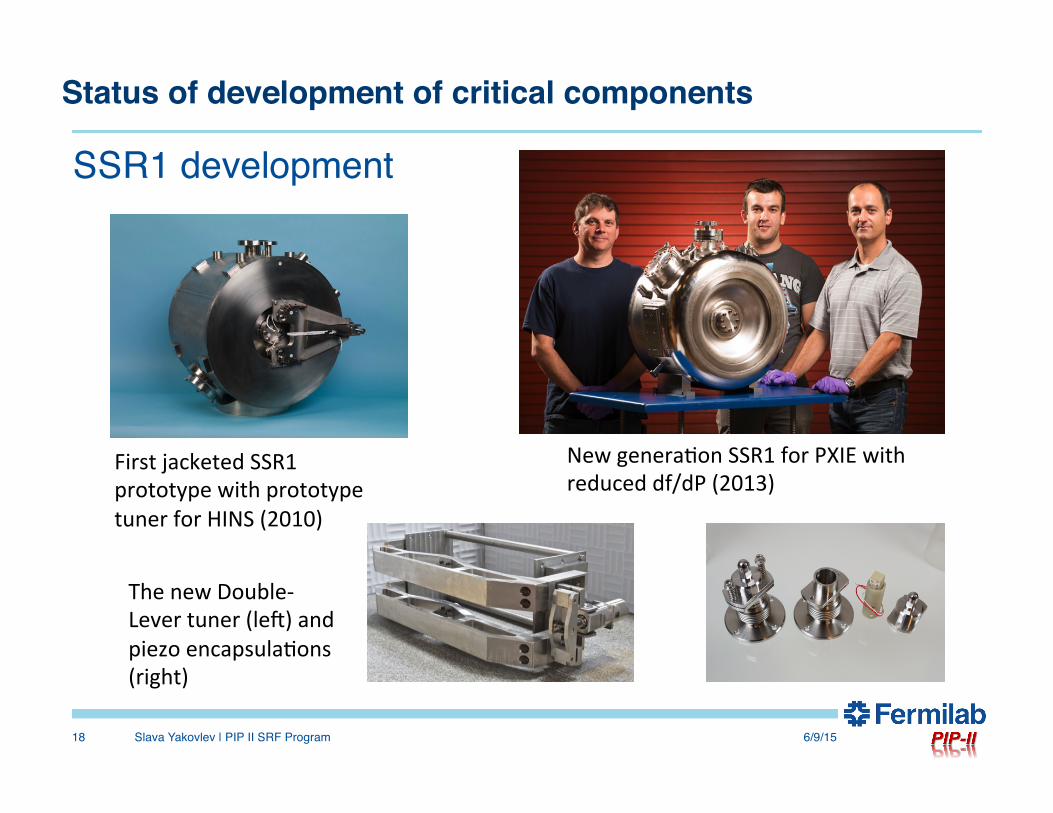
SSR1 development
6/9/15Slava Yakovlev | PIP II SRF Program18
First jacketed SSR1 prototype with prototype tuner for HINS (2010)
New genera?on SSR1 for PXIE with reduced df/dP (2013)
The new Double-‐Lever tuner (len) and piezo encapsula?ons (right)
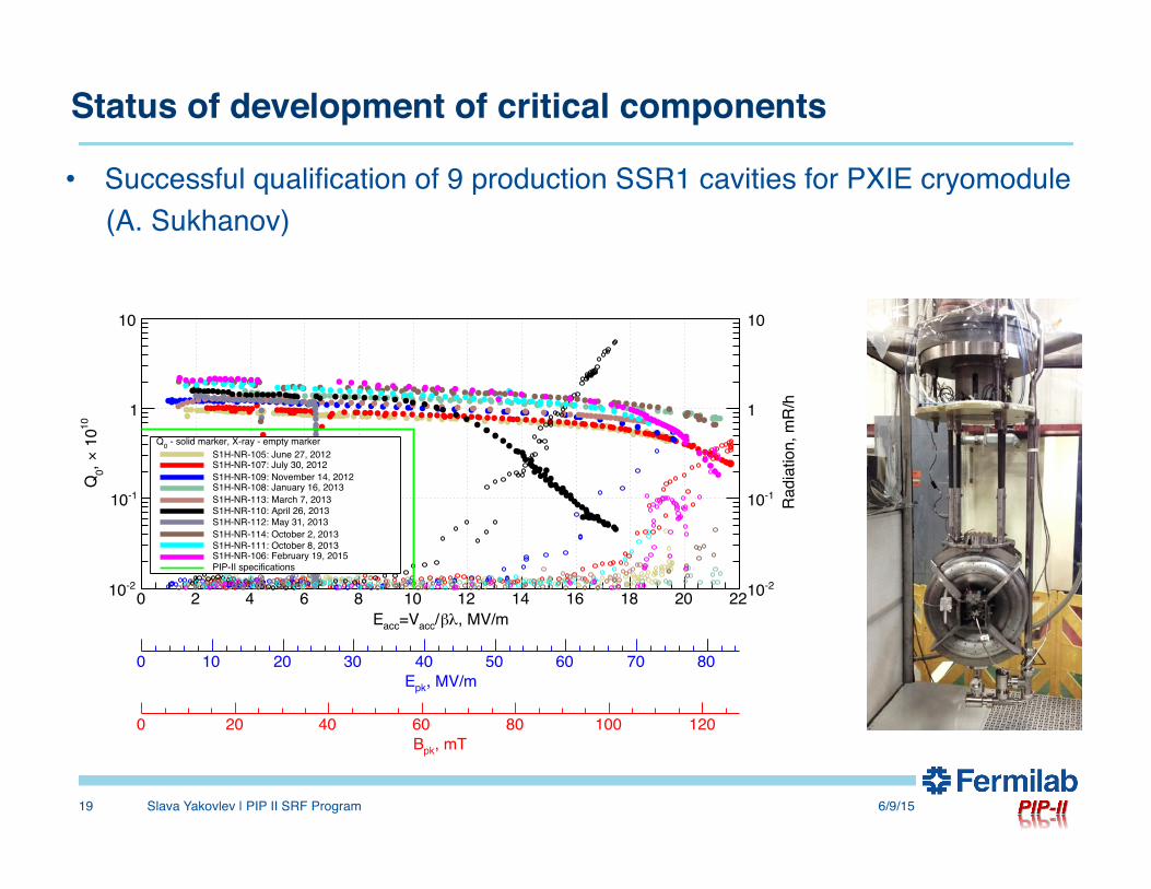
• Successful qualification of 9 production SSR1 cavities for PXIE cryomodule (A. Sukhanov)
6/9/15Slava Yakovlev | PIP II SRF Program19
, MV/mλβ/acc=VaccE0 2 4 6 8 10 12 14 16 18 20 22
10 1
0×, 0
Q
-210
-110
1
10
Radi
atio
n, m
R/h
-210
-110
1
10
, MV/mpkE0 10 20 30 40 50 60 70 80
, mTpkB0 20 40 60 80 100 120
- solid marker, X-ray - empty marker0QS1H-NR-105: June 27, 2012S1H-NR-107: July 30, 2012S1H-NR-109: November 14, 2012S1H-NR-108: January 16, 2013S1H-NR-113: March 7, 2013S1H-NR-110: April 26, 2013S1H-NR-112: May 31, 2013S1H-NR-114: October 2, 2013S1H-NR-111: October 8, 2013S1H-NR-106: February 19, 2015PIP-II specifications
Status of development of critical components
Status of development of critical components
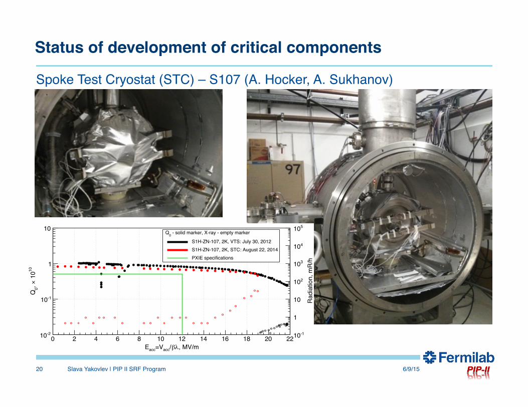
Spoke Test Cryostat (STC) – S107 (A. Hocker, A. Sukhanov)
6/9/15Slava Yakovlev | PIP II SRF Program20
S1H-NR-107
•Q0 vs Eacc
9
, MV/mλβ/acc=VaccE0 2 4 6 8 10 12 14 16 18 20 22
10 1
0×, 0
Q
-210
-110
1
10
Rad
iatio
n, m
R/h
-110
1
10
210
310
410
510
, MV/mpkE0 10 20 30 40 50 60 70 80
, mTpkB0 20 40 60 80 100 120
- solid marker, X-ray - empty marker0Q
S1H-ZN-107, 2K, VTS: July 30, 2012S1H-ZN-107, 2K, STC: August 22, 2014PXIE specifications
Status of development of critical components
6/9/15Slava Yakovlev | PIP II SRF Program21
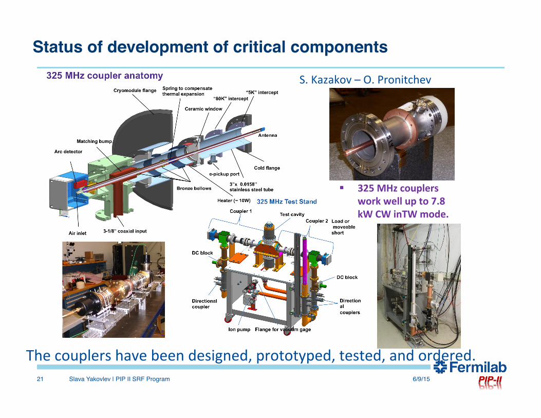
§ 325 MHz couplers work well up to 7.8 kW CW inTW mode.
S. Kazakov – O. Pronitchev
The couplers have been designed, prototyped, tested, and ordered.
Status of development of critical components
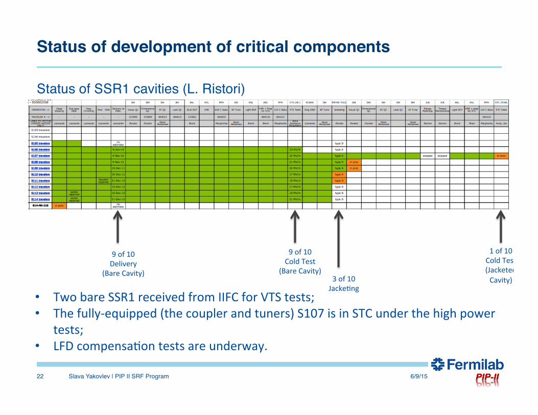
Status of SSR1 cavities (L. Ristori)
6/9/15Slava Yakovlev | PIP II SRF Program22
9 of 10 Delivery
(Bare Cavity)
9 of 10 Cold Test
(Bare Cavity) 3 of 10 Jacke?ng
1 of 10 Cold Test (Jacketed Cavity)
• Two bare SSR1 received from IIFC for VTS tests; • The fully-‐equipped (the coupler and tuners) S107 is in STC under the high power
tests; • LFD compensa?on tests are underway.
Status of development of critical components
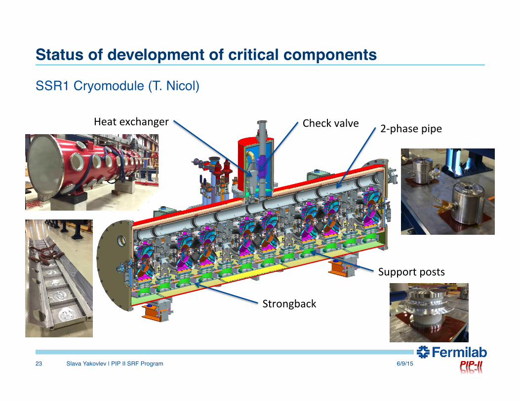
SSR1 Cryomodule (T. Nicol)
6/9/15Slava Yakovlev | PIP II SRF Program23
Support posts
2-‐phase pipe Heat exchanger Check valve
Strongback
Status of development of critical components
6/9/15Slava Yakovlev | PIP II SRF Program24
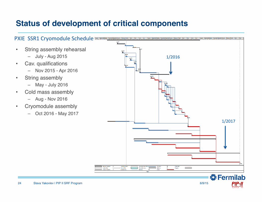
• String assembly rehearsal – July - Aug 2015
• Cav. qualifications– Nov 2015 - Apr 2016
• String assembly– May - July 2016
• Cold mass assembly – Aug - Nov 2016
• Cryomodule assembly – Oct 2016 - May 2017
1/2016
1/2017
PXIE SSR1 Cryomodule Schedule
Status of development of critical components
6/9/15Slava Yakovlev | PIP II SRF Program25
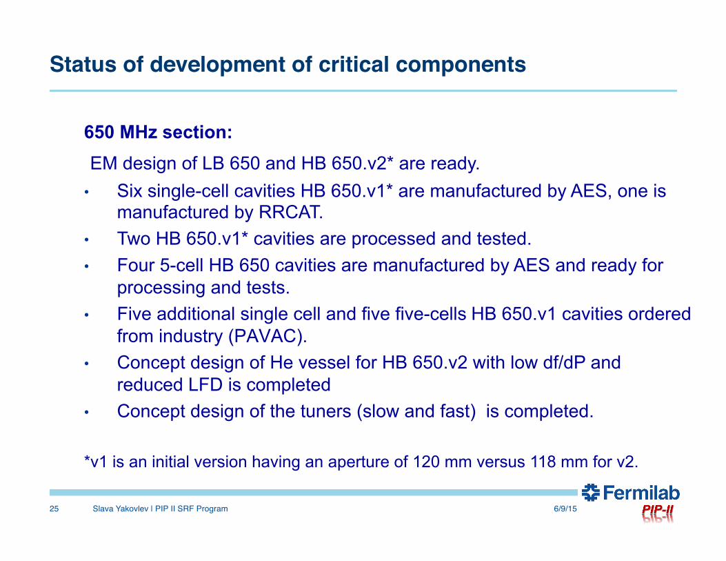
650 MHz section: EM design of LB 650 and HB 650.v2* are ready. • Six single-cell cavities HB 650.v1* are manufactured by AES, one is
manufactured by RRCAT. • Two HB 650.v1* cavities are processed and tested. • Four 5-cell HB 650 cavities are manufactured by AES and ready for
processing and tests. • Five additional single cell and five five-cells HB 650.v1 cavities ordered
from industry (PAVAC). • Concept design of He vessel for HB 650.v2 with low df/dP and
reduced LFD is completed • Concept design of the tuners (slow and fast) is completed. *v1 is an initial version having an aperture of 120 mm versus 118 mm for v2.
Status of development of critical components
6/9/15Slava Yakovlev | PIP II SRF Program26
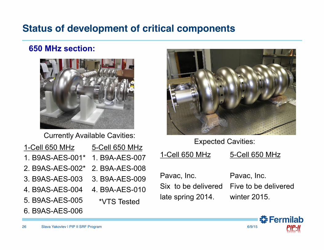
Currently Available Cavities: 1-Cell 650 MHz 1. B9AS-AES-001* 2. B9AS-AES-002* 3. B9AS-AES-003 4. B9AS-AES-004 5. B9AS-AES-005 6. B9AS-AES-006
5-Cell 650 MHz 1. B9A-AES-007 2. B9A-AES-008 3. B9A-AES-009 4. B9A-AES-010
*VTS Tested
Expected Cavities:
1-Cell 650 MHz Pavac, Inc. Six to be delivered late spring 2014.
5-Cell 650 MHz Pavac, Inc. Five to be delivered winter 2015.
650 MHz section:
Status of development of critical components
6/9/15Slava Yakovlev | PIP II SRF Program27
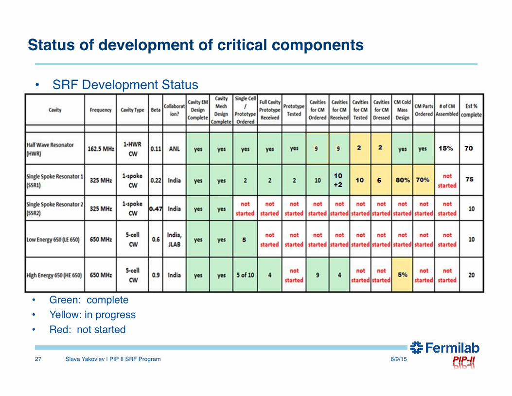
• SRF Development Status
• Green: complete• Yellow: in progress• Red: not started
TD organization, staffing and facilities
6/9/15Slava Yakovlev | PIP II SRF Program28
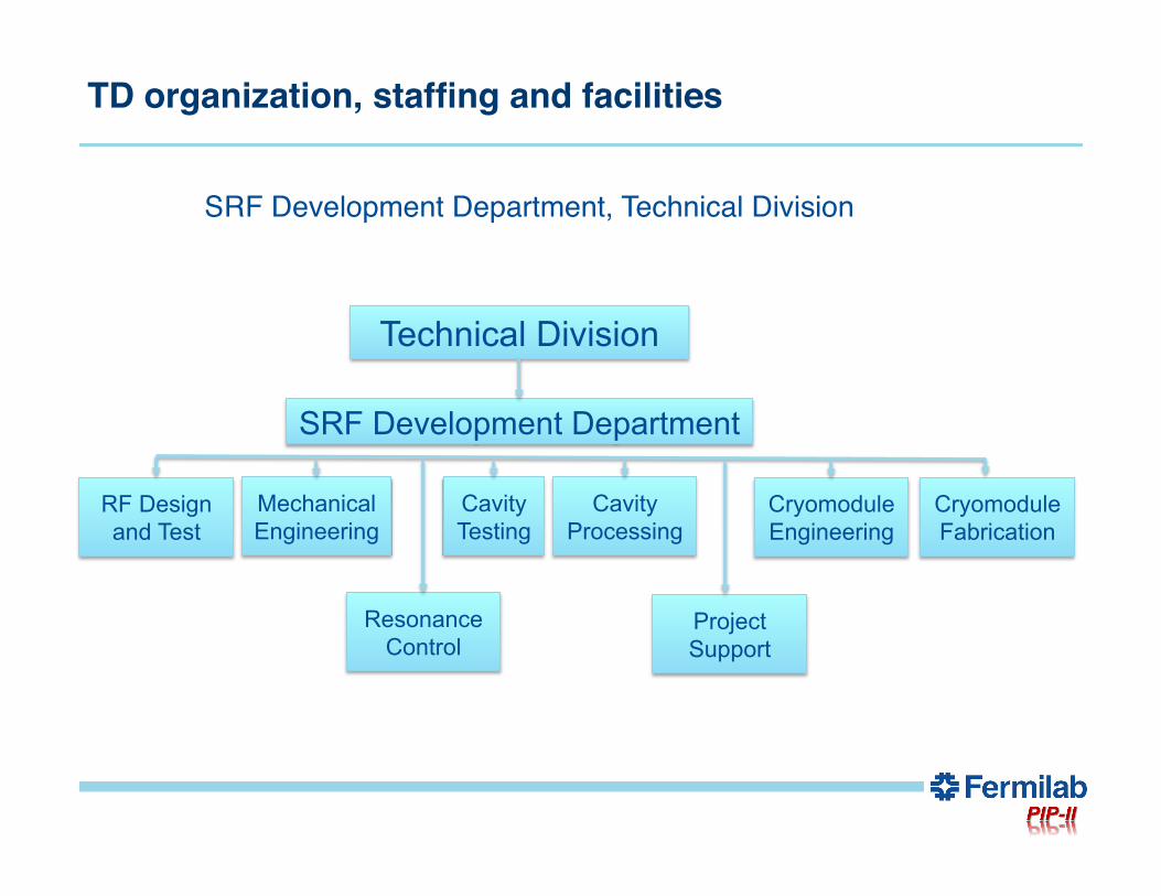
SRF Development Department, Technical Division
Technical Division
SRF Development Department
RF Design and Test
Mechanical Engineering
Cavity Testing
Cavity Processing
Cryomodule Engineering
Cryomodule Fabrication
Resonance Control
Project Support
TD organization, staffing and facilities
6/9/15Slava Yakovlev | PIP II SRF Program29
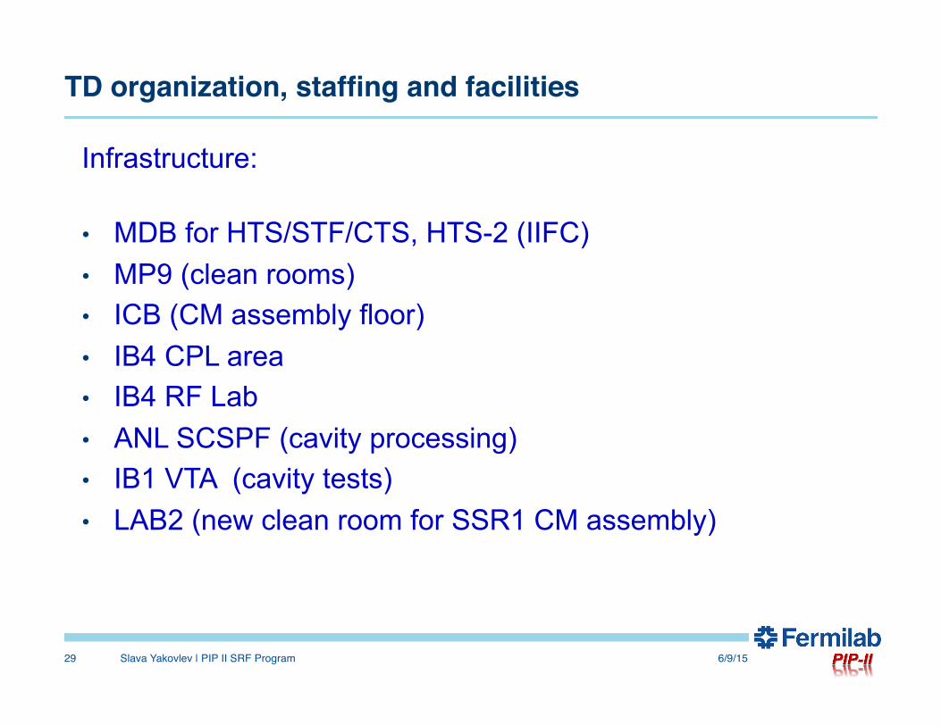
Infrastructure:
• MDB for HTS/STF/CTS, HTS-2 (IIFC) • MP9 (clean rooms) • ICB (CM assembly floor) • IB4 CPL area • IB4 RF Lab • ANL SCSPF (cavity processing) • IB1 VTA (cavity tests) • LAB2 (new clean room for SSR1 CM assembly)
LCLS II issues
6/9/15Slava Yakovlev | PIP II SRF Program30
• LCLS II project R&D and design is very well aligned to the
PIP II.• PIP-II construction will be starting up as LCLS-II
construction rolls off• Technical staff will move from LCLS-II onto PIP-II • PIP-II will benefit from the extensive cryomodule
production experience of LCLS-II• R&D challenges are very similar between the two projects
(High Q0, Resonance Control)
Summary• The linac reference design is ready; • The main challenges and technical risks are identified; • Relevant R&D are organized and are in progress; • The concept design of most critical parts is done; • The low energy part of the linac is in process of fabrication; • We work intensively in the frame of IIFC collaboration on the 650 MHz CM
design;• TD organization and staffing are ready for the project;• LCLS II activity is well-aligned to PIP II
6/9/15Slava Yakovlev | PIP II SRF Program31
Related Documents