6/21/2018 Automatic Transaxle/Transmission - 4F27E - Pinpoint Tests - OSC Equipped Vehicle - Diagnosis and Testing • 2010 Ford Transit Connec… https://www.motologic.com/car/34bb00c0-d588-012d-31ea-19005f6e69db/article/eb680009f3fe95095f421333a67b0225 1/33 Report a problem with this article 307-01 Automatic Transaxle/Transmission — 4F27E 2010 Transit Connect DIAGNOSIS AND TESTING Procedure revision date: 04/20/2011 Pinpoint Tests — OSC Equipped Vehicle Special Tool(s) Fluke 77-IV Digital Multimeter FLU77-4 or equivalent Pressure Gauge Assembly 307-004 (T57L-77820-A) Vehicle Communication Module (VCM) and Integrated Diagnostic System (IDS) software with appropriate hardware, or equivalent scan tool Any time an electrical connector or solenoid body is disconnected, inspect the connector for terminal condition, corrosion and contamination. Also inspect the connector seal for damage. Clean, repair or install new as necessary. Shift Solenoid Pre-Diagnosis Use the Solenoid Operation Chart — Converter Disengaged or Solenoid Operation Chart — Engaged when carrying out Pinpoint Test A. Refer to Specifications in this section. Solenoid Operation Chart — Converter Disengaged Selector Lever Position PCM Commanded Gear SSA (ON/OFF) SSB (ON/OFF) SSC PWM SSD PWM SSE PWM P/N P/N On Off Off Off Off R R Off Off Off Off Off D 1 Off Off Off On On 1(M) On On Off Off On 2 Off Off Off Off On 3 Off Off Off Off Off 2010 Transit Connect

Welcome message from author
This document is posted to help you gain knowledge. Please leave a comment to let me know what you think about it! Share it to your friends and learn new things together.
Transcript
6/21/2018 Automatic Transaxle/Transmission - 4F27E - Pinpoint Tests - OSC Equipped Vehicle - Diagnosis and Testing • 2010 Ford Transit Connec…
https://www.motologic.com/car/34bb00c0-d588-012d-31ea-19005f6e69db/article/eb680009f3fe95095f421333a67b0225 1/33
Report a problem with this article
307-01 Automatic Transaxle/Transmission — 4F27E 2010 Transit Connect
DIAGNOSIS AND TESTING Procedure revision date: 04/20/2011
Pinpoint Tests — OSC Equipped Vehicle
Special Tool(s)
Fluke 77-IV Digital Multimeter FLU77-4 or equivalent
Pressure Gauge Assembly 307-004 (T57L-77820-A)
Vehicle Communication Module (VCM) and Integrated Diagnostic System (IDS) software withappropriate hardware, or equivalent scan tool
Any time an electrical connector or solenoid body is disconnected, inspect the connector for terminal condition,corrosion and contamination. Also inspect the connector seal for damage. Clean, repair or install new asnecessary.
Shift Solenoid Pre-Diagnosis
Use the Solenoid Operation Chart — Converter Disengaged or Solenoid Operation Chart — Engaged whencarrying out Pinpoint Test A. Refer to Specifications in this section.
Solenoid Operation Chart — Converter Disengaged
Selector Lever Position PCM Commanded Gear SSA (ON/OFF) SSB (ON/OFF) SSC PWM SSD PWM SSE PWM
P/N P/N On Off Off Off Off
R R Off Off Off Off Off
D 1 Off Off Off On On
1(M) On On Off Off On
2 Off Off Off Off On
3 Off Off Off Off Off
2010 Transit Connect

6/21/2018 Automatic Transaxle/Transmission - 4F27E - Pinpoint Tests - OSC Equipped Vehicle - Diagnosis and Testing • 2010 Ford Transit Connec…
https://www.motologic.com/car/34bb00c0-d588-012d-31ea-19005f6e69db/article/eb680009f3fe95095f421333a67b0225 2/33
Selector Lever Position PCM Commanded Gear SSA (ON/OFF) SSB (ON/OFF) SSC PWM SSD PWM SSE PWM
4 On Off On Off Off
With an ON/OFF solenoid, OFF = No Hydraulic Flow.
With a PWM solenoid, OFF = Full Hydraulic Flow.
Solenoid Operation Chart — Converter Engaged
Selector Lever Position PCM Commanded D Gear SSA (ON/OFF) SSB (ON/OFF) SSC PWM SSD PWM SSE PWM
D 3 Off On On Off Off
4 On On On Off Off
With a ON/OFF solenoid, OFF = No Hydraulic Flow.
With a PWM solenoid, OFF = Full Hydraulic Flow.
Pinpoint Tests
Refer to Wiring Diagrams Cell 29 for schematic and connector information.
PINPOINT TEST A : SHIFT AND TCC SOLENOIDS (ONLY)
NOTE: Refer to the Transaxle Vehicle Harness Connector illustration within the Transaxle Connector Layoutsprocedure in this section.
NOTE: Refer to the Transaxle Internal Harness Connectors illustration within the Transaxle Connector Layoutsprocedure in this section.
NOTE: Read and record all DTCs. All Transmission Range (TR) sensor and Output Shaft Speed (OSS) DTCsmust be repaired before entering output state control.
A1 ELECTRONIC DIAGNOSTICS SET UP
Make sure the transaxle harness connector is fully seated, terminals are fully engaged in connectorand in good condition before proceeding.
Connect the scan tool.
Ignition ON.
Access the shift solenoids and the Torque Converter Clutch (TCC) solenoid PIDs.

6/21/2018 Automatic Transaxle/Transmission - 4F27E - Pinpoint Tests - OSC Equipped Vehicle - Diagnosis and Testing • 2010 Ford Transit Connec…
https://www.motologic.com/car/34bb00c0-d588-012d-31ea-19005f6e69db/article/eb680009f3fe95095f421333a67b0225 3/33
Is communication with the PCM established?
Yes GO to A2.
No REPEAT procedure to access the shift solenoid and TCC solenoid PIDs. If the scan tool cannotestablish communication with the PCM, REFER to the Powertrain Control/Emissions Diagnosis (PC/ED)manual for diagnosis of the PCM.
A2 WIGGLE TEST
Using the scan tool, select the shift solenoids and TCC solenoid PIDs to be commanded:SSA.
SSB.
SSC.
SSD.
SSE.
TCC.
Select PIDs to be monitored:SSPCA_F.
SSPCB_F.
SSPCC_F.
SSPCD_F.
SSPCE_F.
TCC.
Using the scan tool, command the suspect shift solenoid(s) ON.
Wiggle all wiring and connectors to the transaxle. Monitor the shift solenoid fault state for changes.
Does the suspect shift solenoid(s) fault PID state change?
Yes REPAIR the circuit. TEST the system for normal operation.
No GO to A3.
A3 CHECK SOLENOID FUNCTION
Turn each shift solenoid ON and OFF.

6/21/2018 Automatic Transaxle/Transmission - 4F27E - Pinpoint Tests - OSC Equipped Vehicle - Diagnosis and Testing • 2010 Ford Transit Connec…
https://www.motologic.com/car/34bb00c0-d588-012d-31ea-19005f6e69db/article/eb680009f3fe95095f421333a67b0225 4/33
Does the shift solenoid turn ON and OFF when commanded and can the shift solenoid activation beheard?
Yes GO to A4.
No GO to A5.
A4 DRIVE TEST
Select PIDs GEAR_OSC, TCC, TRAN_RAT and GEAR_RAT.
Test drive the vehicle while an assistant commands upshifts, downshifts and TCC engagement whilemonitoring the TRAN_RAT and GEAR_RAT PIDs.
Does the transaxle upshift and downshift or TCC engage/disengage when commanded and is theTRAN_RAT PID equal to the GEAR_RAT PID?
Yes CLEAR all DTCs. ROAD TEST to verify if concern is still present. If concern is still present, CHECK thevehicle wiring harness for an intermittent condition. If the condition is still not present, GO to A2. REFERto Diagnosis By Symptom in this section to diagnose shift or TCC concern.
No REFER to Diagnosis By Symptom in this section to diagnose an internal transaxle mechanical concern.
A5 CHECK FOR AN OPEN CIRCUIT
Ignition OFF.
Disconnect: Transaxle Vehicle Harness C199.
Disconnect: PCM C175T.
Visually inspect all wires, pins and connectors for damage.
Measure the resistance of the suspect shift solenoid circuit between the PCM transaxle electricalC175T and transaxle vehicle harness C199.
Shift Solenoid and Circuit Transaxle C199 Pin PCM C175T Pin
Shift Solenoid A (SSA) 15S-TA23 (GN/YE) C199-6 C175T-11
Shift Solenoid B (SSB) 15S-TA24 (GN/BU) C199-8 C175T-23
Shift Solenoid C (SSC) 15S-TA63 (GN/BK) C199-3 C175T-45
Shift Solenoid D (SSD) 15S-TA64 (GN/OG) C199-9 C175T-33
Shift Solenoid E (SSE) 15S-TA65 (GN/WH) C199-1 C175T-44

6/21/2018 Automatic Transaxle/Transmission - 4F27E - Pinpoint Tests - OSC Equipped Vehicle - Diagnosis and Testing • 2010 Ford Transit Connec…
https://www.motologic.com/car/34bb00c0-d588-012d-31ea-19005f6e69db/article/eb680009f3fe95095f421333a67b0225 5/33
Is the resistance less than 5 ohms?
Yes GO to A6.
No REPAIR the circuit(s) for an open. TEST the system for normal operation.
A6 CHECK FOR SHORTS TO GROUND
Measure the resistance between transaxle vehicle harness, C199 and ground.
Shift Solenoid and Circuit Transaxle C199 Pin Ground
SSA 15S-TA23 (GN/YE) C199-6 Ground
SSB 15S-TA24 (GN/BU) C199-8 Ground
SSC 15S-TA63 (GN/BK) C199-3 Ground
SSD 15S-TA64 (GN/OG) C199-9 Ground
SSE 15S-TA65 (GN/WH) C199-1 Ground
Is the resistance greater than 10,000 ohms?
Yes GO to A7.
No REPAIR the circuit(s) for a short to ground. TEST the system for normal operation.
A7 CHECK FOR SHORT TO BATTERY VOLTAGE
Ignition ON.
Measure the voltage between transaxle vehicle harness, C199 and ground.
Shift Solenoid and Circuit Transaxle C199 Pin Ground
SSA 15S-TA23 (GN/YE) C199-6 Ground
SSB 15S-TA24 (GN/BU) C199-8 Ground
SSC 15S-TA63 (GN/BK) C199-3 Ground

6/21/2018 Automatic Transaxle/Transmission - 4F27E - Pinpoint Tests - OSC Equipped Vehicle - Diagnosis and Testing • 2010 Ford Transit Connec…
https://www.motologic.com/car/34bb00c0-d588-012d-31ea-19005f6e69db/article/eb680009f3fe95095f421333a67b0225 6/33
Shift Solenoid and Circuit Transaxle C199 Pin Ground
SSD 15S-TA64 (GN/OG) C199-9 Ground
SSE 15S-TA65 (GN/WH) C199-1 Ground
Is any voltage present?
Yes REPAIR the circuit(s) for a short to power. TEST the system for normal operation.
No GO to A8.
A8 CHECK SOLENOID RESISTANCE
Measure and record the resistance between transaxle vehicle harness C199, component side and aknown good ground on the transaxle case. Compare the resistance values to the table.
Shift Solenoid and Pin Resistance Specification Range
SSA pin 6 10.9-26.2 ohms
SSB pin 8 10.9-26.2 ohms
SSC pin 3 1.0-4.2 ohms
SSD pin 9 1.0-4.2 ohms
SSE pin 1 1.0-4.2 ohms
Is the resistance within specification?
Yes GO to A9.
No GO to A10.
A9 CHECK THE PCM
Connect: PCM C175T.
Using the scan tool, select the following PIDs to be commanded:SSASSB

6/21/2018 Automatic Transaxle/Transmission - 4F27E - Pinpoint Tests - OSC Equipped Vehicle - Diagnosis and Testing • 2010 Ford Transit Connec…
https://www.motologic.com/car/34bb00c0-d588-012d-31ea-19005f6e69db/article/eb680009f3fe95095f421333a67b0225 7/33
SSCSSDSSETCC
Using the scan tool, command the suspect solenoid(s) ON while measuring the voltage betweentransaxle harness C199 and ground.
Shift Solenoid and Circuit Transaxle Vehicle Harness C199 Ground
SSA 15S-TA23 (GN/YE) C199-6 Ground
SSB 15S-TA24 (GN/BU) C199-8 Ground
SSC 15S-TA63 (GN/BK) C199-3 Ground
SSD 15S-TA64 (GN/OG) C199-9 Ground
SSE 15S-TA65 (GN/WH) C199-1 Ground
Is the voltage above 10 volts?
Yes REFER to Diagnosis By Symptom in this section for a stuck solenoid or other non-functioning internalcomponents.
No INSTALL a new PCM. REFER to Section 303-14.
A10 CHECK THE TRANSAXLE INTERNAL WIRING HARNESS FOR A SHORT TO GROUND
Remove the transmission fluid pan. Refer to Transmission Fluid Pan in this section.
Disconnect the shift solenoid electrical connector(s).1 — SSA
2 — SSB
3 — SSC
4 — SSD
5 — SSE

6/21/2018 Automatic Transaxle/Transmission - 4F27E - Pinpoint Tests - OSC Equipped Vehicle - Diagnosis and Testing • 2010 Ford Transit Connec…
https://www.motologic.com/car/34bb00c0-d588-012d-31ea-19005f6e69db/article/eb680009f3fe95095f421333a67b0225 8/33
Measure the resistance between transaxle internal wiring harness C199, component side and aknown good ground on the transaxle case or solenoid body.
Is the resistance greater than 10,000 ohms?
Yes GO to A11.
No INSTALL a new transaxle internal wiring harness. TEST the system for normal operation.
A11 CHECK THE TRANSAXLE INTERNAL WIRING HARNESS FOR AN OPEN
Measure the resistance between transaxle internal harness connector pin 6 and transaxle internalharness solenoid connector pin 6.
Measure the resistance between transaxle internal harness connector pin 8 and transaxle internalharness solenoid connector pin 8.
Measure the resistance between transaxle internal harness connector pin 3 and transaxle harnesssolenoid connector pin 3.

6/21/2018 Automatic Transaxle/Transmission - 4F27E - Pinpoint Tests - OSC Equipped Vehicle - Diagnosis and Testing • 2010 Ford Transit Connec…
https://www.motologic.com/car/34bb00c0-d588-012d-31ea-19005f6e69db/article/eb680009f3fe95095f421333a67b0225 9/33
Measure the resistance between transaxle internal harness connector pin 9 and transaxle harnesssolenoid connector pin 9.
Measure the resistance between transaxle internal harness connector pin 1 and transaxle harnesssolenoid connector pin 1.
Is the resistance less than 5 ohms?
Yes If SSA or SSB is suspected, INSTALL a new solenoid. If SSC , SSD or SSE is suspected, GO to A12.
No INSTALL a new transaxle internal harness. TEST the system for normal operation.
A12 CHECK THE TRANSAXLE INTERNAL HARNESS GROUND CIRCUIT
Measure the resistance between transaxle internal harness connector pins and ground eye hook asfollows:
SSC — Between transaxle internal harness solenoid connector pin 11 and ground eyehook.
SSD — Between transaxle internal harness solenoid connector pin 12 and ground eyehook.
SSE — Between transaxle internal harness solenoid connector pin 10 and ground eyehook.

6/21/2018 Automatic Transaxle/Transmission - 4F27E - Pinpoint Tests - OSC Equipped Vehicle - Diagnosis and Testing • 2010 Ford Transit Connec…
https://www.motologic.com/car/34bb00c0-d588-012d-31ea-19005f6e69db/article/eb680009f3fe95095f421333a67b0225 10/33
Is the resistance less than 5 ohms?
Yes INSTALL a new solenoid. TEST the system for normal operation.
No INSTALL a new transaxle internal harness. TEST the system for normal operation.
PINPOINT TEST B : TFT SENSOR
NOTE: Refer to the Transaxle Vehicle Harness Connector illustration within the Transaxle Connector Layoutsprocedure in this section.
NOTE: Refer to the Transaxle Internal Harness Connectors illustration within the Transaxle Connector Layoutsprocedure in this section.
B1 ELECTRONIC DIAGNOSTICS SET UP
Make sure the transaxle harness connector is fully seated, terminals are fully engaged in theconnector and in good condition before proceeding.
Connect the scan tool.
Ignition ON.
Access the Transmission Fluid Temperature (TFT) PIDs.
Is communication with the PCM established?
Yes GO to B2.
No REPEAT procedure to access the TFT PIDs. If the scan tool cannot establish communication with thePCM, REFER to the Powertrain Control/Emissions Diagnosis (PC/ED) manual for diagnosis of PCM.
B2 WARM-UP/COOL-DOWN CYCLE VERIFICATION
While monitoring the TFT PIDs, carry out the following test: If transaxle is cold, run transaxle to warmit up. If transaxle is warm, allow transaxle to cool down.

6/21/2018 Automatic Transaxle/Transmission - 4F27E - Pinpoint Tests - OSC Equipped Vehicle - Diagnosis and Testing • 2010 Ford Transit Connec…
https://www.motologic.com/car/34bb00c0-d588-012d-31ea-19005f6e69db/article/eb680009f3fe95095f421333a67b0225 11/33
Do the TFT PIDs increase as the transaxle is warmed up or decrease as the transaxle is cooled or doesthe TFT or TFTV drop in and out of range?
Yes If the TFT PIDs increase as the transaxle is warmed or decrease as the transaxle is cooled, CLEAR allDTCs. ROAD TEST to verify if concern is still present. If concern is still present, REFER to Diagnosis BySymptom in this section to diagnose transaxle overheating. If the TFT drops in and out of range,INSPECT for intermittent concern in the internal/external harness, sensor or connector.
No GO to B3.
B3 CHECK VEHICLE HARNESS FOR A SHORT TO POWER
Disconnect: Transaxle Vehicle Harness C199.
Disconnect: PCM C175T.
Visually inspect all wires and connectors for damage.
Measure the voltage between transaxle vehicle harness C199-5, circuit 15S-TA17 (GN/OG) andground.
Measure the voltage between transaxle vehicle harness C199-4, circuit 9-TA36 (BN/GN) and ground.
Is any voltage present?
Yes REPAIR the circuit for a short to power. TEST the system for normal operation.
No GO to B4.

6/21/2018 Automatic Transaxle/Transmission - 4F27E - Pinpoint Tests - OSC Equipped Vehicle - Diagnosis and Testing • 2010 Ford Transit Connec…
https://www.motologic.com/car/34bb00c0-d588-012d-31ea-19005f6e69db/article/eb680009f3fe95095f421333a67b0225 12/33
B4 CHECK THE VEHICLE HARNESS FOR A SHORT TO GROUND
Measure the resistance between transaxle vehicle harness C199-5, circuit 15S-TA17 (GN/OG) andground.
Measure the resistance between transaxle vehicle harness C199-4, circuit 9-TA36 (BN/GN) andground.
Is the resistance greater than 10,000 ohms?
Yes GO to B5.
No REPAIR the circuit for a short to ground. TEST the system for normal operation.
B5 CHECK VEHICLE HARNESS FOR OPEN
Measure the resistance between transaxle vehicle harness C199-5, circuit 15S-TA17 (GN/OG) andPCM C175T-19, circuit 15S-TA17 (GN/OG).
Measure the resistance between transaxle vehicle harness C199-4, circuit 9-TA36 (BN/GN) and PCMC175T-40, circuit 9-PA1A (BN/RD).

6/21/2018 Automatic Transaxle/Transmission - 4F27E - Pinpoint Tests - OSC Equipped Vehicle - Diagnosis and Testing • 2010 Ford Transit Connec…
https://www.motologic.com/car/34bb00c0-d588-012d-31ea-19005f6e69db/article/eb680009f3fe95095f421333a67b0225 13/33
Is the resistance less than 5 ohms?
Yes GO to B6.
No REPAIR the circuit. TEST the system for normal operation.
B6 CHECK THE RESISTANCE OF THE TFT SENSOR
Measure the resistance between transaxle vehicle harness connector pin 5 (component side,transaxle internal harness), and transaxle vehicle harness connector pin 4 (component side,transaxle internal harness).
Record the resistance.
Resistance should be approximately in the following ranges:-20°C (-4°F) — 236-317 K ohms.
0°C (32°F) — 83.2-107 K ohms.
20°C (68°F) — 33.5-41.2 K ohms.
40°C (104°F) — 14.6-17.6 K ohms.
60°C (140°F) — 7.08-8.01 K ohms.
80°C (176°F) — 3.61-4.06 K ohms.
100°C (212°F) — 1.96-2.20 K ohms.
120°C (248°F) — 1.13-1.25 K ohms.
130°C (266°F) — 0.87-0.96 K ohms.
Is the resistance in the range?
6/21/2018 Automatic Transaxle/Transmission - 4F27E - Pinpoint Tests - OSC Equipped Vehicle - Diagnosis and Testing • 2010 Ford Transit Connec…
https://www.motologic.com/car/34bb00c0-d588-012d-31ea-19005f6e69db/article/eb680009f3fe95095f421333a67b0225 14/33
Yes GO to B7.
No GO to B8.
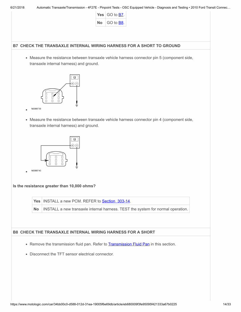
B7 CHECK THE TRANSAXLE INTERNAL WIRING HARNESS FOR A SHORT TO GROUND
Measure the resistance between transaxle vehicle harness connector pin 5 (component side,transaxle internal harness) and ground.
Measure the resistance between transaxle vehicle harness connector pin 4 (component side,transaxle internal harness) and ground.
Is the resistance greater than 10,000 ohms?
Yes INSTALL a new PCM. REFER to Section 303-14.
No INSTALL a new transaxle internal harness. TEST the system for normal operation.
B8 CHECK THE TRANSAXLE INTERNAL WIRING HARNESS FOR A SHORT
Remove the transmission fluid pan. Refer to Transmission Fluid Pan in this section.
Disconnect the TFT sensor electrical connector.

6/21/2018 Automatic Transaxle/Transmission - 4F27E - Pinpoint Tests - OSC Equipped Vehicle - Diagnosis and Testing • 2010 Ford Transit Connec…
https://www.motologic.com/car/34bb00c0-d588-012d-31ea-19005f6e69db/article/eb680009f3fe95095f421333a67b0225 15/33
Measure the resistance between transaxle vehicle harness connector pin 5 (component side,transaxle internal harness) and ground.
Measure the resistance between transaxle vehicle harness connector pin 4 (component side,transaxle internal harness) and ground.
Measure the resistance between C199-4 and C199-5, component side.
Is the resistance greater than 10,000 ohms?
Yes GO to B9.
No INSTALL a new transaxle internal harness. TEST the system for normal operation.
B9 CHECK THE TRANSAXLE INTERNAL HARNESS FOR AN OPEN

6/21/2018 Automatic Transaxle/Transmission - 4F27E - Pinpoint Tests - OSC Equipped Vehicle - Diagnosis and Testing • 2010 Ford Transit Connec…
https://www.motologic.com/car/34bb00c0-d588-012d-31ea-19005f6e69db/article/eb680009f3fe95095f421333a67b0225 16/33
Measure the resistance between transaxle vehicle harness connector pin 5 (component side,transaxle internal harness), and TFT sensor internal harness connector pin 5.
Measure the resistance between transaxle vehicle harness connector pin 4 (component side,transaxle internal harness), and TFT sensor internal harness connector pin 4.
Is the resistance less than 5 ohms?
Yes INSTALL a new TFT sensor.
No INSTALL a new transaxle internal harness. TEST the system for normal operation.
PINPOINT TEST C : TR SENSOR
NOTE: Refer to the Transmission Range (TR) Sensor Vehicle Harness Connector illustration within theTransaxle Connector Layouts procedure in this section.
NOTE: Refer to the Transmission Range (TR) Sensor Diagnosis PID Chart within the Transaxle ConnectorLayouts procedure in this section.
NOTE: DTC P0705 may also be set from an open ground in the tail lamp circuit. Check and repair tail lampcircuit as necessary.
C1 VERIFY TR SENSOR ALIGNMENT
Using a scan tool, view the TRD, TRL, TRN, TRP and TRR PIDs to determine if an internal fault ispresent in the Transmission Range (TR) sensor, refer to the Transmission Range (TR) SensorDiagnostic PID Chart in Transaxle Connector Layouts in this section.
If an electrical issue exists in the TR sensor electrical circuit, 2 or more binary positions willshow 1s.
Verify TR sensor alignment.
6/21/2018 Automatic Transaxle/Transmission - 4F27E - Pinpoint Tests - OSC Equipped Vehicle - Diagnosis and Testing • 2010 Ford Transit Connec…
https://www.motologic.com/car/34bb00c0-d588-012d-31ea-19005f6e69db/article/eb680009f3fe95095f421333a67b0225 17/33
Is the TR sensor correctly aligned?
Yes GO to C2.
No ADJUST the TR sensor. TEST the system for normal operation.
C2 VERIFY SELECTOR LEVER CABLE/LINKAGE ADJUSTMENT
Verify that the selector lever cable/linkage is correctly adjusted. Refer to Section 307-05.
Is the selector lever cable/linkage correctly adjusted?
Yes GO to C3.
No ADJUST the selector lever cable/linkage REFER to Section 307-05. TEST the system for normaloperation.
C3 CHECK THE TRANSAXLE POWER SUPPLY CIRCUIT
Disconnect: TR Sensor C167.
Ignition ON.
Measure the voltage between TR sensor C167-1 and ground.
Is the voltage greater than 10 volts?
Yes GO to C5.
No GO to C4.
C4 CHECK PDB FUSE 26 (10A)
Ignition ON.

6/21/2018 Automatic Transaxle/Transmission - 4F27E - Pinpoint Tests - OSC Equipped Vehicle - Diagnosis and Testing • 2010 Ford Transit Connec…
https://www.motologic.com/car/34bb00c0-d588-012d-31ea-19005f6e69db/article/eb680009f3fe95095f421333a67b0225 18/33
Check fuse: Power Distribution Box (PDB) 26 (10A).
Is the resistance less than 5 ohms?
Yes REPAIR circuit 15-TA18 (GN/OG) for an open. TEST the system for normal operation.
No REPAIR circuit 15-TA18 (GN/OG) for a short to ground. TEST the system for normal operation.
C5 CHECK THE VEHICLE HARNESS FOR A SHORT TO POWER
Select PARK.
Ignition OFF.
Disconnect: PCM C175T.
Ignition ON.
Measure the voltage between TR sensor C167 pins 2, 3, 4, 5, 7 and 8 and ground using the followingtable:
TR Sensor Circuit TR Sensor C167 Pin Ground
15S-TA37A (GN/YE) Park C167-5 Ground
15-TA42 (GN/WH) M1 C167-3 Ground
15-TA41 (GN/OG) M2 C167-7 Ground
15S-TA40 (GN/BK) Drive C167-2 Ground
15S-TA38 (GN/BU) Reverse C167-4 Ground
15S-TA39 (GN/RD) Neutral C167-8 Ground
Is any voltage present?
Yes REPAIR the circuit(s) for a short to power.
No GO to C6.
C6 CHECK THE VEHICLE HARNESS FOR A SHORT TO GROUND
Measure the resistance between TR sensor C167 pins 2, 3, 4, 5, 7 and 8 and ground using thefollowing table:
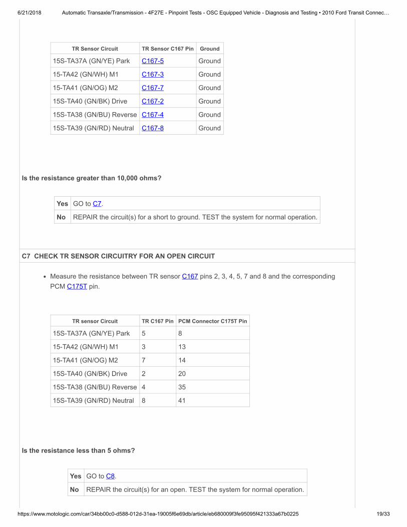
6/21/2018 Automatic Transaxle/Transmission - 4F27E - Pinpoint Tests - OSC Equipped Vehicle - Diagnosis and Testing • 2010 Ford Transit Connec…
https://www.motologic.com/car/34bb00c0-d588-012d-31ea-19005f6e69db/article/eb680009f3fe95095f421333a67b0225 19/33
TR Sensor Circuit TR Sensor C167 Pin Ground
15S-TA37A (GN/YE) Park C167-5 Ground
15-TA42 (GN/WH) M1 C167-3 Ground
15-TA41 (GN/OG) M2 C167-7 Ground
15S-TA40 (GN/BK) Drive C167-2 Ground
15S-TA38 (GN/BU) Reverse C167-4 Ground
15S-TA39 (GN/RD) Neutral C167-8 Ground
Is the resistance greater than 10,000 ohms?
Yes GO to C7.
No REPAIR the circuit(s) for a short to ground. TEST the system for normal operation.
C7 CHECK TR SENSOR CIRCUITRY FOR AN OPEN CIRCUIT
Measure the resistance between TR sensor C167 pins 2, 3, 4, 5, 7 and 8 and the correspondingPCM C175T pin.
TR sensor Circuit TR C167 Pin PCM Connector C175T Pin
15S-TA37A (GN/YE) Park 5 8
15-TA42 (GN/WH) M1 3 13
15-TA41 (GN/OG) M2 7 14
15S-TA40 (GN/BK) Drive 2 20
15S-TA38 (GN/BU) Reverse 4 35
15S-TA39 (GN/RD) Neutral 8 41
Is the resistance less than 5 ohms?
Yes GO to C8.
No REPAIR the circuit(s) for an open. TEST the system for normal operation.

6/21/2018 Automatic Transaxle/Transmission - 4F27E - Pinpoint Tests - OSC Equipped Vehicle - Diagnosis and Testing • 2010 Ford Transit Connec…
https://www.motologic.com/car/34bb00c0-d588-012d-31ea-19005f6e69db/article/eb680009f3fe95095f421333a67b0225 20/33
C8 CHECK THE TR SENSOR RESISTANCE
Measure the resistance between TR sensor C167 pins, component side, using the following table:
TR Position TR C167 Pin TR C167 Pin
TR Position TR C167 Pin TR C167 Pin
PARK C167-1 C167-5
REVERSE C167-1 C167-4
NEUTRAL C167-1 C167-8
DRIVE C167-1 C167-2
M2 C167-1 C167-7
M1 C167-1 C167-3
PARK/NEUTRAL C167-6 C167-9
Are the resistances less than 1,000 ohms?
Yes INSTALL a new PCM. REFER to Section 303-14.
No INSTALL a new TR sensor. REFER to Transmission Range (TR) Sensor in this section. TEST thesystem for normal operation.
PINPOINT TEST D : LPC PCA SOLENOID
NOTE: Refer to the Transaxle Vehicle Harness Connector illustration within the Transaxle Connector Layoutsprocedure in this section.
NOTE: Read and record all DTCs.
D1 ELECTRONIC DIAGNOSTICS SET UP
Make sure the transaxle harness connector is fully seated, terminals are fully engaged in theconnector and in good condition before proceeding.
Connect the scan tool.
Ignition ON.
Access the Pressure Control Solenoid A (PCA) solenoid PIDs.
Is communication with the PCM established?

6/21/2018 Automatic Transaxle/Transmission - 4F27E - Pinpoint Tests - OSC Equipped Vehicle - Diagnosis and Testing • 2010 Ford Transit Connec…
https://www.motologic.com/car/34bb00c0-d588-012d-31ea-19005f6e69db/article/eb680009f3fe95095f421333a67b0225 21/33
Yes GO to D2.
No REPEAT procedure to access the PCA solenoid PIDs. If the scan tool cannot establish communicationwith the PCM, REFER to the Powertrain Control/Emissions Diagnosis (PC/ED) manual for diagnosis ofPCM.
D2 SOLENOID FUNCTIONAL TEST
Remove the line pressure tap plug.
Install a 1/8 x 28-to-1/8 x 28 pipe thread adapter into the line pressure tap.
Install the Hydraulic Pressure Gauge on the adapter.
Select PCA.
Increase engine speed above 1,500 rpm.
Using the scan tool, command the line pressure to 50, 70, 90, 110, 130 or 150 psi while monitoringthe pressure gauge.
Once the test is complete, remove the 1/8 x 28-to-1/8 x 28 pipe thread adapter and install the linepressure tap plug.
Tighten to 13 Nm (115 lb-in).
Does the pressure reading match the commanded pressure?
Yes CLEAR DTCs. TEST the system for normal operation.
No GO to D3.

6/21/2018 Automatic Transaxle/Transmission - 4F27E - Pinpoint Tests - OSC Equipped Vehicle - Diagnosis and Testing • 2010 Ford Transit Connec…
https://www.motologic.com/car/34bb00c0-d588-012d-31ea-19005f6e69db/article/eb680009f3fe95095f421333a67b0225 22/33
D3 CHECK THE VEHICLE HARNESS FOR A SHORT TO POWER
Ignition OFF.
Disconnect: Transaxle Vehicle Harness C199.
Disconnect: PCM C175T.
Visually inspect all wires and connectors for damage.
Ignition ON.
Measure the voltage between transaxle vehicle harness C199-2, circuit 91S-TA17 (BK/RD) andground.
Measure the voltage between transaxle vehicle harness C199-7, circuit 8-TA36 (WH/GN) and ground.
Is any voltage present?
Yes REPAIR the circuit for a short to power. TEST the system for normal operation.
No GO to D4.
D4 CHECK THE VEHICLE HARNESS FOR A SHORT TO GROUND
Measure the resistance between transaxle vehicle harness C199-2, circuit 91S-TA17 (BK/RD) andground.

6/21/2018 Automatic Transaxle/Transmission - 4F27E - Pinpoint Tests - OSC Equipped Vehicle - Diagnosis and Testing • 2010 Ford Transit Connec…
https://www.motologic.com/car/34bb00c0-d588-012d-31ea-19005f6e69db/article/eb680009f3fe95095f421333a67b0225 23/33
Measure the resistance between transaxle vehicle harness C199-7, circuit 8-TA36 (WH/GN) andground.
Is the resistance greater than 10,000 ohms?
Yes GO to D5.
No REPAIR the circuit(s) for a short to ground. TEST the system for normal operation.
D5 CHECK THE VEHICLE HARNESS FOR AN OPEN CIRCUIT
Ignition OFF.
Measure the resistance between transaxle vehicle harness C199-2, circuit 91S-TA17 (BK/RD) andPCM C175T-50, circuit 91S-TA17 (BK/RD).
Measure the resistance between transaxle vehicle harness C199-7, circuit 8-TA36 (WH/GN) andPCM C175T-43, circuit 8-TA36 (WH/GN).

6/21/2018 Automatic Transaxle/Transmission - 4F27E - Pinpoint Tests - OSC Equipped Vehicle - Diagnosis and Testing • 2010 Ford Transit Connec…
https://www.motologic.com/car/34bb00c0-d588-012d-31ea-19005f6e69db/article/eb680009f3fe95095f421333a67b0225 24/33
Is the resistance less than 5 ohms?
Yes GO to D6.
No REPAIR the circuit for an open. TEST the system for normal operation
D6 CHECK SOLENOID RESISTANCE
Measure the resistance between transaxle C199-2, component side and ground.
Measure the resistance between transaxle C199-7, component side and ground.
Is the resistance between 2.4 and 7.3 ohms?
Yes INSTALL a new PCM. REFER to Section 303-14.
No GO to D7.
D7 CHECK THE TRANSAXLE INTERNAL WIRING HARNESS FOR A SHORT TO GROUND
Remove the transmission fluid pan. Refer to Transmission Fluid Pan in this section.

6/21/2018 Automatic Transaxle/Transmission - 4F27E - Pinpoint Tests - OSC Equipped Vehicle - Diagnosis and Testing • 2010 Ford Transit Connec…
https://www.motologic.com/car/34bb00c0-d588-012d-31ea-19005f6e69db/article/eb680009f3fe95095f421333a67b0225 25/33
Disconnect the Line Pressure Control (LPC) electrical connector.
Measure the resistance between transaxle vehicle harness connector pin 2 (component side,transaxle internal harness) and ground.
Measure the resistance between transaxle vehicle harness connector pin 7 (component side,transaxle internal harness) and ground.
Is the resistance greater than 10,000 ohms?
Yes GO to D8.
No INSTALL a new transaxle internal harness. TEST the system for normal operation.
D8 CHECK THE TRANSAXLE INTERNAL HARNESS FOR AN OPEN
Measure the resistance between transaxle vehicle harness connector pin 2 (component side,transaxle internal harness) and transaxle internal harness connector pin 2.

6/21/2018 Automatic Transaxle/Transmission - 4F27E - Pinpoint Tests - OSC Equipped Vehicle - Diagnosis and Testing • 2010 Ford Transit Connec…
https://www.motologic.com/car/34bb00c0-d588-012d-31ea-19005f6e69db/article/eb680009f3fe95095f421333a67b0225 26/33
Measure the resistance between transaxle vehicle harness connector pin 7 (component side,transaxle internal harness) and transaxle internal harness connector pin 7.
Is the resistance less than 5 ohms?
Yes INSTALL a new LPC solenoid. TEST the system for normal operation.
No INSTALL a new transaxle internal harness. TEST the system for normal operation.
PINPOINT TEST E : TSS SENSOR AND OSS SENSOR
NOTE: Refer to the Turbine Shaft Speed (TSS) Sensor Vehicle Harness Connector and Output ShaftSpeed (OSS) Sensor Vehicle Harness Connector illustrations within the Transaxle Connector Layoutsprocedure in this section.
E1 ELECTRONIC DIAGNOSTICS SET UP
Make sure the transaxle harness connector is fully seated, terminals are fully engaged in theconnector and in good condition before proceeding.
Connect the scan tool.
Ignition ON.
Access the following PIDs: TSS or OSS.
Is communication with the PCM established?
Yes GO to E2.
No REPEAT procedure to access the speed sensor PIDs. If the scan tool cannot establish communication

6/21/2018 Automatic Transaxle/Transmission - 4F27E - Pinpoint Tests - OSC Equipped Vehicle - Diagnosis and Testing • 2010 Ford Transit Connec…
https://www.motologic.com/car/34bb00c0-d588-012d-31ea-19005f6e69db/article/eb680009f3fe95095f421333a67b0225 27/33
with the PCM, REFER to the Powertrain Control/Emissions Diagnosis (PC/ED) manual for diagnosis ofPCM.
E2 DRIVE CYCLE TEST
While monitoring the appropriate speed sensor PID, drive the vehicle so that the transaxle upshiftsand downshifts through all gears.
Does the TSS or OSS sensor PID increase and decrease with engine and vehicle speed?
Yes GO to E3.
No If the TSS or OSS sensor PID does not increase and decrease with engine and vehicle speed,INSPECT for open or short in vehicle harness, sensor, a PCM concern or internal hardware concern.GO to E4.
E3 DRIVE CYCLE TEST ERRATIC
While monitoring the appropriate sensor PID, drive the vehicle so that the transaxle upshifts anddownshifts through all gears.
Is the TSS or OSS Sensor PID signal erratic (drop to zero or near zero and return to normal operation)?
Yes If the sensor signal is erratic, INSPECT for intermittent concern in the harness, sensor or connector. GOto E4.
No CLEAR all DTCs. TEST the system for normal operation.
E4 CHECK THE VEHICLE WIRING HARNESS FOR A SHORT TO POWER
Ignition OFF.
Disconnect: TSS Sensor C143 or OSS Sensor C193.
Disconnect: PCM C175T.
Ignition ON.
Measure the voltage between TSS sensor C143-1, circuit 8-TA27 (WH/VT) and ground.

6/21/2018 Automatic Transaxle/Transmission - 4F27E - Pinpoint Tests - OSC Equipped Vehicle - Diagnosis and Testing • 2010 Ford Transit Connec…
https://www.motologic.com/car/34bb00c0-d588-012d-31ea-19005f6e69db/article/eb680009f3fe95095f421333a67b0225 28/33
Measure the voltage between TSS sensor C143-2, circuit 9-TA27 (BN/WH) and ground.
Measure the voltage between OSS sensor C193-1, 8-RJ29 (WH/BU) and ground.
Measure the voltage between OSS sensor C193-2, 9-RJ29 (BN/BU) and ground.
Is there any voltage?
Yes REPAIR the circuit for a short to power. TEST the system for normal operation.
No GO to E5.
E5 CHECK THE VEHICLE WIRING HARNESS FOR A SHORT TO GROUND
Measure the resistance between TSS sensor C143-1, circuit 8-TA27 (WH/VT) and ground.

6/21/2018 Automatic Transaxle/Transmission - 4F27E - Pinpoint Tests - OSC Equipped Vehicle - Diagnosis and Testing • 2010 Ford Transit Connec…
https://www.motologic.com/car/34bb00c0-d588-012d-31ea-19005f6e69db/article/eb680009f3fe95095f421333a67b0225 29/33
Measure the resistance between TSS sensor C143-2, circuit 9-TA27 (BN/WH) and ground.
Measure the resistance between OSS sensor C193-1, 8-RJ29 (WH/BU) and ground.
Measure the resistance between OSS sensor C193-2, 9-RJ29 (BN/BU) and ground.
Is the resistance greater than 10,000 ohms?
Yes GO to E6.
No REPAIR the circuit for a short to ground. TEST the system for normal operation.
E6 CHECK THE VEHICLE WIRING HARNESS FOR AN OPEN CIRCUIT
Ignition OFF.

6/21/2018 Automatic Transaxle/Transmission - 4F27E - Pinpoint Tests - OSC Equipped Vehicle - Diagnosis and Testing • 2010 Ford Transit Connec…
https://www.motologic.com/car/34bb00c0-d588-012d-31ea-19005f6e69db/article/eb680009f3fe95095f421333a67b0225 30/33
Measure the resistance between TSS sensor C143-1, circuit 8-TA27 (WH/VT) and PCM C175T-37,circuit 8-TA27 (WH/VT).
Measure the resistance between TSS sensor C143-2, circuit 9-TA27 (BN/WH) and PCM C175T-40,circuit 9-PA1A (BN/RD).
Measure the resistance between OSS sensor C193-1, circuit 8-RJ29 (WH/BU) and PCM C175T-4,circuit 8-RJ29 (WH/BU).
Measure the resistance between OSS sensor C193-2, circuit 9-RJ29 (BN/BU) and PCM C175T-15,circuit 9-RJ29 (BN/BU).
Is the resistance less than 5 ohms?
Yes GO to E7.
No REPAIR the circuit for an open. TEST the system for normal operation.

6/21/2018 Automatic Transaxle/Transmission - 4F27E - Pinpoint Tests - OSC Equipped Vehicle - Diagnosis and Testing • 2010 Ford Transit Connec…
https://www.motologic.com/car/34bb00c0-d588-012d-31ea-19005f6e69db/article/eb680009f3fe95095f421333a67b0225 31/33
E7 CHECK RESISTANCE OF TSS SENSOR OR OSS SENSOR
For the TSS sensor, measure the resistance between TSS sensor connector pin 1, component sideand TSS sensor connector pin 2, component side. Record the resistance. Resistance should be asfollows below:
Sensor Resistance Temperature
Sensor Resistance Temperature
TSS 273-333 ohms -20°C (-4°F)
TSS 330-390 ohms 21°C (70°F)
TSS 487-601 ohms 160°C (320°F)
For the OSS sensor, measure the resistance between OSS connector pin 1, component side andOSS connector pin 2, component side. Record the resistance. Resistance should be as followsbelow:
Sensor Resistance Temperature
OSS 675-775 ohms -20°C (-4°F)
OSS 800- 920 ohms 21°C (70°F)
OSS 1210-1390 ohms 160°C (320°F)

6/21/2018 Automatic Transaxle/Transmission - 4F27E - Pinpoint Tests - OSC Equipped Vehicle - Diagnosis and Testing • 2010 Ford Transit Connec…
https://www.motologic.com/car/34bb00c0-d588-012d-31ea-19005f6e69db/article/eb680009f3fe95095f421333a67b0225 32/33
Is the resistance within specification for the appropriate sensor?
Yes GO to E8.
No INSTALL a new sensor. TEST the system for normal operation.
E8 CHECK SENSORS FOR SHORT TO GROUND
For TSS sensor, measure the resistance between TSS sensor connector pin 1, component side andground.
For OSS , measure the resistance between OSS connector pin 1, component side and ground.
Is the resistance greater than 10,000 ohms?
Yes INSTALL a new PCM. TEST the system for normal operation. If the condition still exists, REFER toDiagnosis By Symptom in this section for diagnosis of shift or torque converter concerns.
No INSTALL a new TSS or OSS sensor. TEST the system for normal operation. If the condition still exists,REFER to Diagnosis By Symptom in this section for diagnosis of shift or torque converter concerns.
Copyright © 2013 Ford Motor Company

6/21/2018 Automatic Transaxle/Transmission - 4F27E - Pinpoint Tests - OSC Equipped Vehicle - Diagnosis and Testing • 2010 Ford Transit Connec…
https://www.motologic.com/car/34bb00c0-d588-012d-31ea-19005f6e69db/article/eb680009f3fe95095f421333a67b0225 33/33
Related Documents


![[164] pinpoint](https://static.cupdf.com/doc/110x72/587065dc1a28ab48378b4f79/164-pinpoint.jpg)
