Pin Jointed Systems Examples of pin - jointed frame structures. Assumptions - no bending moments , no shear Axial forces only Locating tension and compression members by inspection Sum of forces at joints Unstable structures and redundant members Statically determinate structures Three dimensional pin jointed systems

Pin Jointed Systems
Dec 12, 2015
beam
Welcome message from author
This document is posted to help you gain knowledge. Please leave a comment to let me know what you think about it! Share it to your friends and learn new things together.
Transcript

Pin Jointed Systems
Examples of pin - jointed frame structures.Assumptions - no bending moments , no shearAxial forces onlyLocating tension and compression members by inspectionSum of forces at jointsUnstable structures and redundant membersStatically determinate structuresThree dimensional pin jointed systems

Examples of pin jointed truss structures


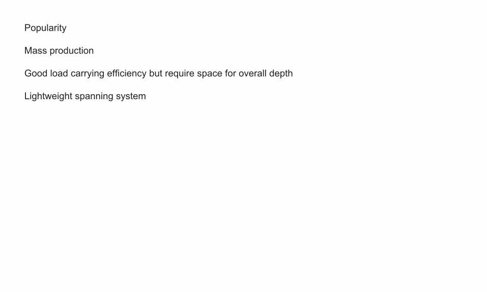
Popularity
Mass production
Good load carrying efficiency but require space for overall depth
Lightweight spanning system

Key design considerations
Length of compression members is minimsed.
(Strut strength is inversely proportional to square of its length. More on this soon.)
For tension members, length is irrelevant to load-carrying capacity.
Loads are applied at nodes only joints are pinned and assumed to be frictionless.
Members are subject to axial compression or tension .
There is no bending or shear on members.

Finding compression and tension by inspection.


Imagine the effect of cutting or removing a member, the struc-ture becomes unstable or a mechanism.
The nodes at the ends of the removed member will either move closer together (member is in compression) or further apart (member is in tension).

Compressive member
Tensile member

horizontal and vertical equilibrium
and simultaneous equations

Resolve forces perpendicular to one of the unknown forces
This eliminates one force from the problem as it does not have a component perpendicular to itself
First resolve components of AC perp to AC
Then resolve parallel to AC.

But it can be easier you - can draw it at scale

In this example, brackets are on 5m spacing, the total design load of the pipes is 3.8kN/m determine the value of the forces in the members bycalculation or by drawing.
Tip:Start with joint E Only consider joints where there are two unknowns.Remember vertical and horizontal equilibrium.allow 0.5kN per node for self weight of truss.

Unstable structures and redundant members
The ability to look at a structure and mentally remove a member to identify compressive and tensile members can also help identifying unstable structures (mechanisms)
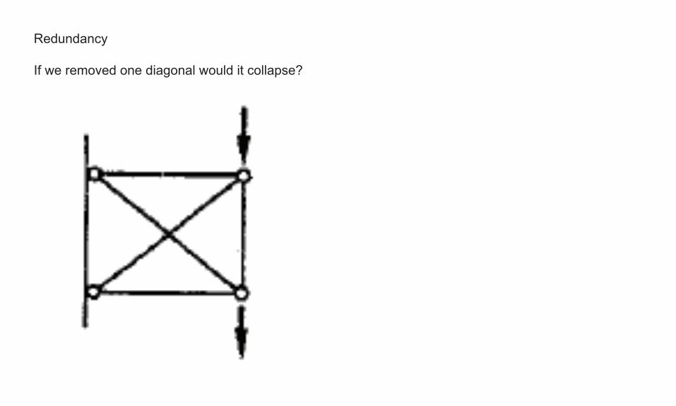
Redundancy
If we removed one diagonal would it collapse?

No, so it has one redundancy.
but as the structure is loaded one member is in compression and one is in tension.

Conisder this situation, both diagonal members are required if they can only act in tension.
Some care is needed to ensure a redundant or unloaded member is not required for a particular load case.

We looked atExamples of pin - jointed frame structures.Assumptions - no bending moments , no shearAxial forces onlyLocating tension and compression members by inspectionSum of forces at jointsUnstable structures and redundant membersStatically determinate structures
If these principles can be extended into three dimensions we are dealing with space trusses.

The basic building block of a plane truss is the triangle
The basic building block of a space truss is a tetrahedron
The same principles apply but now we require a minimum of six reactions (plane trusses needed three)
three vertical to stop movement in the z direction and three more in the x-y plane to prevent rotation and movement in x or y directions.

Forces have to be resolved in three directions
Determine forces in all members for this simple structure when lift-ing 100kNForce in memberDA = 152.2.kNDE = 152.2kNDB = DC = 1109.9kNEB = 119.1kNEC= 37.5 kN


Related Documents