DOCUMENT RESUME ED 099 496 CE 002 573 TITLE Progress Check Module; Basic Electricity and Electronics Individualized Learning System. Progress Check Booklet. INSTITUTION Bureau of Naval Personnel, Washington, D.C. PIMP? NO NATEDTRA-34258-PC PUB DATE Jan 74 won 297p.; For other modules in the series, see CE 0C2 574-589. Several series of blank pages were removed from the document EDRS PRICE MF-$0.75 HC- $13.80 PLUS POSTAGE DESCRIPTORS *Electricity; *Electronics; Individualized Instruction; Individualized Programs; Individual Tests; Military Training; Post Secondary Education; Programed Instruction; *Programed Materials; Testing; Trade and Industrial Education ABSTPACT The Progress Check Booklet is designed to be used by the student working in the programed course to determine if he has mastered the concepts in the course booklets on: electrical current; voltage; resistance; measuring current and voltage in series circuits; relationships of current, voltage, and resistance; parallel circuits; combination circuits and voltage dividers, induction; relationships of current, counter EMF (electromotive force), and voltage in LB (inductive resistance) circuits; transformers; capacitance; series AC (alternatin1g current) resistive-reactive circuits; series AC, RLC (inductive-resistive-capacitive) circuits and resonance; and parallel AC resistive-reactive circuits. Each progress check lesson consists of self-tests with the accompanying answers. Correct answers to all questions indicate to the student that he is ready to proceed to the next lesson. Appended are trigonometric tables and a summary of each of the modules. (Author/BP)

Welcome message from author
This document is posted to help you gain knowledge. Please leave a comment to let me know what you think about it! Share it to your friends and learn new things together.
Transcript

DOCUMENT RESUME
ED 099 496 CE 002 573
TITLE Progress Check Module; Basic Electricity andElectronics Individualized Learning System. ProgressCheck Booklet.
INSTITUTION Bureau of Naval Personnel, Washington, D.C.PIMP? NO NATEDTRA-34258-PCPUB DATE Jan 74won 297p.; For other modules in the series, see CE 0C2
574-589. Several series of blank pages were removedfrom the document
EDRS PRICE MF-$0.75 HC- $13.80 PLUS POSTAGEDESCRIPTORS *Electricity; *Electronics; Individualized
Instruction; Individualized Programs; IndividualTests; Military Training; Post Secondary Education;Programed Instruction; *Programed Materials; Testing;Trade and Industrial Education
ABSTPACTThe Progress Check Booklet is designed to be used by
the student working in the programed course to determine if he hasmastered the concepts in the course booklets on: electrical current;voltage; resistance; measuring current and voltage in seriescircuits; relationships of current, voltage, and resistance; parallelcircuits; combination circuits and voltage dividers, induction;relationships of current, counter EMF (electromotive force), andvoltage in LB (inductive resistance) circuits; transformers;capacitance; series AC (alternatin1g current) resistive-reactivecircuits; series AC, RLC (inductive-resistive-capacitive) circuitsand resonance; and parallel AC resistive-reactive circuits. Eachprogress check lesson consists of self-tests with the accompanyinganswers. Correct answers to all questions indicate to the studentthat he is ready to proceed to the next lesson. Appended aretrigonometric tables and a summary of each of the modules.(Author/BP)

BEST CM NAME
NAVEDTRA :34258-PC
U OlIPAATMINT Of ut AO soADUCAtION A Aril PAOI
ft A11016AL. stanturii 0.IDUCATAINI
tty+S OQCUMENT 14As ALI t°Lief° ExACitt At lifTS4t atesaa on CmiGANIZAAt INC. at POINTS 42+ 10E* Oir 00 4. ,;A:,PAYED 00 NOT NEctsyAk r Ata ,6.1sine 0$$ tom. eavoka.EoucaTiow pas ..0$4 C
BASIC ELECTRICITY AND ELECTRONICS
INDIVIDUALIZED LEARNING SYSTEM
PROGRESS CHECKMODULE
Progress Check Booklet
3 CHIEF OF NAVAL EDUCATION AND TRAININGU January 1974

Progress Check
MODULE ONE
Lesson I
Lesson IILesson III
Lesson IVLesson V
AnswersNotes
CONTENTS
ELECTRICAL CURRENT
Electricity and the ElectronElectron MovementSound/Slide, Constructing a Simple CircuitCurrent FlowMeasurement of CurrentSound/Slide, The AmmeterThe AmmeterLessons I - V
Module One
MODULE lvo VOLTAGE
Lesson I
Lesson II
Lesson III
Lesson IVLesson V
Lesson VI
AnswersNotes
MODULE THREE
IE td
EMF from Chemical ActionMagnetismSound/Slide, Electromagnetic inductionElectromagnetic InductionGenerating AC VoltageSound/Slide, AC-DC Generator OperationUses of AC and DCSound/Slide, DC VoltmeterMeasuring VoltageLesson I - VI
Module Two- nia.,1, e 41. J. let- RESISTANCE
Lesson I
Lesson IILesson IIILesson IVAnswersNotes
Characteristics of ResistanceResistorsResistor IdentificationThe OhmmeterLessons I - IVModule Three - 131a.. ,,, Je ',Ted
NAVEDTRA 34258-PC
MODULE FOUR - MEASURING CURRENT AND VOLTAGE IN SERIES CIRCUITS
Lesson I
Lesson IILesson IIIAnswersNotes
MODULE FIVE
Lesson I
Lesson IILesson IIILesson IVLesson VAnswersNotes
Measuring Current in a Series CircuitVoltage in a Series CircuitThe Multimeter as a VoltmeterLessons 1 - III
Module Four - Rla tk rise., 4 its
- RELATIONSHIPS OF CURRENT, VOLTAGE AND RESISTANCE
Voltage, Current and ResistanceOhm's Law FormulaPowerInternal Resistance
Troubleshooting Series CircuitsLessons I - VModule Five. fa s le.f..1
iii
Page
1
3
5
6
-911
12
14
16
19
23
26
27
30
3435
38
3943
46
4952
575961
63
67
71
74
8081
8789
939596
9899

Progress Check NAVEDTRA 34258-PC
CONTENTS
MODULE SIX - PARALLEL CIRCUITS
Lesson I
Lesson IILesson IIILesson IVAnswersNotes
Rules for Voltage and CurrentRules for Resistance and PowerVariational AnalysisTrout,leshooting Parallel Circuits
Lessons I - IVModule Six -AA.); e.1: d% a
MODULE SEVEN COMBINATION CIRCUITS AND VOLTAGE DIVIDERS
Lesson I
Lesson IILesson IIIAnswersNotes
Solving Complex CircuitsVoltage ReferenceVoltage DividersLessons I - Ill
Module Seven -RiA.A 0/,./e/ed
MODULE EIGHT - INDUCTION
Lesson I
Lesson IILesson IIILesson IVAnswersNotes
MODULE NINE
Lesson 1
Lesson 11
Lesson IiiLesson IVLesson VLesson VIAnswersNotes
ElectromagnetsInductors and Flux DensityInducing a VoltageInduction and inductanceLessons I - IVModule Eight - Slap, A d.Irled
- RELATIONSHIPS OF CURRENT, COUNTER EMF AND
VOLTAGE IN LR CIRCUITS
Rise and Decay of Current and Voltage
LR Time ConstantUniversal Time Constant ChartInductive ReactanceRelationships In Inductive CircuitsPhase Relationships in Inductive Circuits
Lessons ! VI
Module Nine -1404,,i r 06 474
MODULE TEN - TRANSFORMERS
Lesson I
Lesson IILesson IIILesson IVLesson VAnswersNotes
Transformer ConstructionTransformer Theory and OperationTurns and Voltage RatiosPower and CurrentTransformer EfficiencyLessons I - V
Module Ten- Alitftk pp.., de
iv
Page
103
106110
113
116
117
121
125
129
134
135
139141
142
145148
150
153
157160
164
167
169
171
174
177180
182
184
186
189
190

Progress Check
MODULE ELEVEN - CAPACITANCE
Lesson 1
Lesson IILesson IIILesson IVLesson VLesson VILesson VIIAnswersNotes
CONTENTS
The CapacitorTheory of CapacitanceTotal CapacitanceRC Time ConstantsCapacitivePhase and Per RelationshipsCapacitor Design ConsiderationsLessons I VII
Module Eleven - f0"04 elio. ;1- /4 1.'d
MODULE TWELVE - SERIES AC RESISTIVE-REACTIVE CIRCUITS
Lesson I
Lesson IILesson IIILesson IVLesson VLesson VIAnswersNotes
NAVEDTRA 34258-PC
Voltage and Impedance in AC Series CircuitsVector ComputationsRectangular and Polar NotationsVariational Analysis of Series RL CircuitsFrequency Discrimination in RL CircuitsSeries RC CircuitsLesson 1 - VI
Module Twelve - ht ft k d . to d
MODULE THIRTEEN - SERIES AC RLC CIRCUITS AND RESONANCE
Lesson 1 Solving RLC CircuitsLesson 11 Series AC Circuits at ResonanceLesson 111 Resonance in Series RC CircuitsAnswers Lesson I - IIINotes Module Thirteen - i 4. L 4,. it ., de d'o te.41
MODULE FOURTEEN - PARALLEL AC RESISTIVE-REACTIVE CIRCUITS
Lesson 1
Lesson 11Lesson 111Lesson IVLesson VAnswersNotes
Appendix
Solving for Quantities in RL CircuitsVariational Analysis in Parallel CircuitsParallel RC and RLC CircuitsParallel ResonanceEffective Resistance In RL CircuitsLessons I - VModule Fourteen f.3 At eel f , It to
Page
195
197
199
203207210212213215
219222224227
230232236238
241
245
247251
252
257260
262265
268
270271
Trigonometric Tables 275
V

LESSON PROGRESS CHEW.:
Record your answers in the spaces provided. When you have completed
a les!,c:, progress check, compare yetr answers to the correct answers.
The correct answers are located at the end of each module along with
blank pages for notes.
IF YOUR ANSWERS ARE ALL CORRECT, GO ON TO THE NEXT LESSON. IF NOT,
STUDY ANY OF THE OTHER RESOURCES AVAILABLE FOR THAT LESSON UNTIL
YOU CAN ANSWER ALL THE QUESTIONS CORRECTLY.
vi

Progress Check Cne-I
PROGRESS CHECKLESSON I
Electricity and the Electron
1. Labe! the three particles indicated.
2. If a neutral atom contains 10 protons and 14 neutrons,it should contain:
a. 24 electrons.b. 10 electrons.c. 14 electrons.===.9m,
3. The atomic particles which orbit the nucleus are:
a. protons.b. neutrons.c. electrons.
4. The nucleus of an atom is composed of:
a. electrons and neutrons.b. protons and electrons.c. protons, electrons, and neutrons.d. neutrons and protons.
5. Protons and electrons normally are:
a. equal in number.b. equal in size and weight.c. found in the nucleus.
1

Progress Check One-I
6. Electron movement is theoretical because:
11111
a. the effects of electricity are unpredictable.
b. the existence of electricity is not positively known.
c. electron flow or movement cannot be directly observed.
7. Which statement(s) is/are true?
a. The neutron is the lightest partici found in the atom.
b. Electricity is explained by the mc. fnt of protons.
c. The electron is the most mobile ato.dic particle.
d. All atoms have the same atomic structure and contain
the same number of electrons, protons, and neutrons.
e. Atoms may differ from each other in the numbers of
electrons, protons, and neutrons wh ch make up their
structure.
2

Progress Check
PROGRESS CHECKLESSON 11
Electron Movement
1. Label the atomic particles.
A
One-11
2. State the Law of Charged Bodies:
3. Match.
1.
2.
two protonsproton and electron(4.) and (-)
two electrons
a.
b.
attraction
repulsion3.
4.
5. positive and negative6. (+) and (4-)
7. like charges c. neither8. unlike charges9. negative and negative10. positive and positive11. two neutrons
4. Match.
1. weakest attraction to nucleus2. greatest attraction to nucleus3. easiest to free from its atomic
orbit
3

Progress Cheek One-II
5. Which correctly describes "random drift?'
a. the general movement of electrons in one direction througha wire.
b. the occasional straying of electrons from one nuclearorbit to another in the same atom.
c. the undirected movement of free electrons in a wire.d. the haphazard movement of atoms in a wire.
6. correctly describes "free electrons?"
a. electrons which are no longer attached to an atom.b. electrons which maka up the outermost shell of an atom.c. electrons which have become attached to another atom's
nucleus.
7. When an electron is removed from a neutral atom the atom becomesa/an:
1111.111! a. negative ion.b. positive ion.c. uncharged ion.d. free ion.
8. The energy required to free an electron from it's parent atomis known as:
a. potential energy.b. atomic energy.c. ionization potential.d. electromotive force.
Sound/Slide
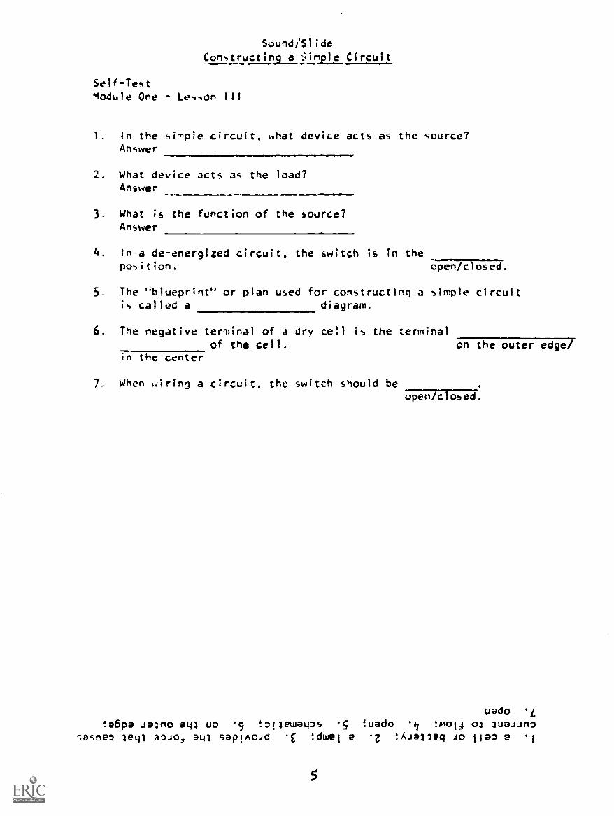
Constructing a dimple Circuit
Self-TestModule One - Lesson III
1. In the simple circuit, what device acts as the source?Answer
2. What device acts as the load?Answer
3. What is the function of the source?Answer
4. In a de-energized circuit, the switch is in theposition. open/closed.
5. The "blueprint" or plan used for constructing a simple circuitis called a diagram.
6. The negative terminal of a dry cell is the terminalof the cell. on the outer edge/
in the center
7. When wiring a circuit, the switch should beopen/closed.
uado L!e6pa Jalmo ato uo 9 !aoewatps 5 !tiado :mol4 of 2u3.1.1n,
7,at.ne, leo a.so4 go sap!Awd .E !dwei e z !Aialleg JO ila 'I
5

Progress Check
PROGRESS CHECKLESSON III
Current Flow
1. Draw a schematic of the circuit shown below.
One-III
2. Which arrow correctly shows the direction of current flow?
Aeo-
B
3. Which correctly describes electron current flow?
a. free electrons moving in one direction.b. the directed drift of positive and negative charges through
a wire.c. the drifting of outermost electrons away fro& their atomic
nuclei.d. the random drift of electrons in a conductor.
6

Progress Check One-III
4. In which circuit will current flow?
a.
b.
c.
d.
e.11=11MINIW
T
F-44-.71t

Progress Check One-III
5. Match.
1. cell a.
2. switch3. lamp b.
4. conductorconductorc.
6. Which arrow points to the negative terminal?
1 A
7. Which statement(s) is/are true?
a. Current will not flow in a circuit unless there is a completepath.
b. When a circuit is closed, there is an incomplete path.c. A circuit is open when there is an incomplete path.d. Current flow in a conductor is from positive to negative.
8

Progress Check One-IV
PROGRESS CHECKLESSON IV
Measurement of Current
1. How many electrons constitute a coulomb of charge? .1=11.=1
2. When two coulombs of charge pass a given point in one-half second,the current is:
a. 2 amperes.b. 4 amperes.
c. 0.5 amperes.d. 1 ampere.
alimilMM=1
3. Which formula is used to determine current flow?
a. Q = T
b. 1 =
c. 1 =Qxtd. t=Qx1
4. Convert to scientific notation.
a. 210b. 0.0431c. 83,000d. 0.001ffil.11
5. Convert to Ocimal numbers.
a. 103
b. 10-I
c. 10-3
d. 105
9
progless Check One-1V
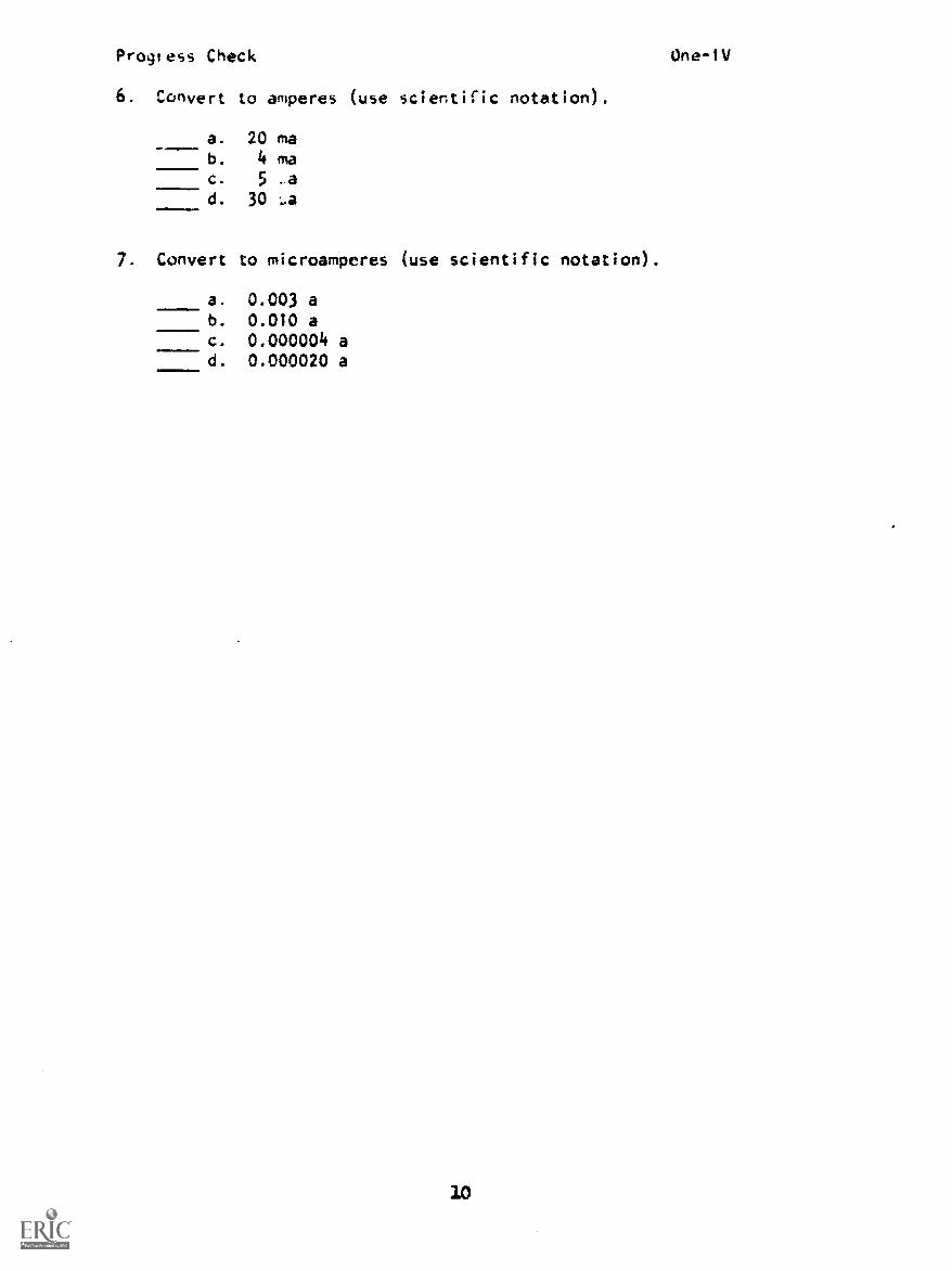
6. Convert to amperes (use scientific notation).
a. 20 mab. 4 mac. 5 .ad. 30
7. Convert to microamperes (use scientific notation)...111.1
a. 0.003 ab. 0.010 ac. 0.000004 ad. 0.000020 a
10

Sound/Slide
The Ammeter
Self-TestModuie One Le, sup' V
1. The unit of measure for current is the2. On an ammeter, the black terminal is and the red
terminal is
3. What indicates that an ammeter is connected with incorrect polarity?Arswer:
4. When an ammeter is to be connected into a circuit, the first step is
5. When an ammeter is properly connected into a simple circuit, themeter is connected so that:a. only a small amount of the total current will pats through the
meter.b. all of the current flowing in the circuit will pa s through the
meter.Answer:
6. A milliampere is equal to ampere(s).7. The name for one millionth of an ampere is one ampere.8. It is good practice to select a meter having a range
than you expect to measure. greater/smaller
BEST COPY AVAILABLE
Jale2.16 !0.113w 't :OHM .9!ci 5 ao az!ElJaua-ap -f7 !uo!lba.ilp Buoim ao u! lnallap
Ilim Jalu!nd al41 .f Japo leo u!) artp!sod 'aA!leflau E !aJadwe 1
U

Progress Check One -V
PROGRESS CHECKLESSON V
The Ammeter
1. Label the parts of the ammeter.
2. Which statements) is/are true?
d,
a. The basic unit of electron current is the ampere.b. When measuring current, the ammeter must be connected in
parallel.The ammeter is used to measure coul bs per second andis represented schematically by
d. Polarity must be observed when conn t ng the ammeter into
the circuit.e. Current readings will be higher when the ammeter Is connected
near the negative terminal of the cell than when connectednear the positive terminal.
3. Which meter is properly connected for taking current measurements?
a. Meter #1b. Meter #2c. Meter #3d. Meter #4
12

Progress Check One-V
4. Which correctly lists the steps for hooking up an ammeter andrecording current?
a. (1) Place switch in closed position.(2) Break circuit and connect meter in series (observe
polarity).(3) Place switch in open position and take current reading.
b. (1) De-energize circuit.
(2) Connect leads, placing the meter in series andobserving polarity.
(3) Energize circuit and take current reading.c. bothd. neither
5. Build the circuit shown below. Then record the current in theblank below.
SE
TS
13
T7 To
DS?

PROGRESS CHECK ANSWERSMODULE ONE
LESSON III
--I--
b
1.
2.
LESSON I
2.
a.
b.
c.
b
electron
neutron
proton
3. c
4. d
5. a
6. c
7. c, e
LESSON II
1. a. proton
b. neutron
c. electron
2. Like charges repel and
unlike charges attract.
3. 1-b 7-b
2 -a 8-a
3-a 9-b
4-b 10-b
5-a 11-c
6-b
4. 1-a
2-c
3-a
5. c
6. a
7. b
8. c
3. a
4. e
5. 1-e
2-d
3-c
4-a
6. a
7. a, c
LESSON IV
1. 6,250,000,000,000,000,000 or 6.25 x 10
electrons
2. b
3. b
4. a. 2.1 x 10²
b. 4.31 x 10⁻²
c. 8.3 x 10⁴
d. 1 x 10⁻³
5. a. 1000
b. 0.1
c. 0.001
d. 100,000
6. a. 2 x 10⁻²
a
b. 4 x 10⁻³a
c. 5 x 10⁻⁶
a
d. 3 x 10⁻⁵
a
7. a. 3 x 1031,a
b. 1 x 10⁴
...a
c. 4 x 100:a
d. 2 x 101ua
314
PROGRESS CHECK ANSWERS MODULE ONE
LESSON V1. a. positive termiral
P. pointer (need10C. negative termilald. meter dial (scale)
2. a, c, and d3. c
4. b
5. About 0.2 amps
IF YOUR ANSWERS ARE ALL CORRECT, YOU MAY TAKE THE MODULE TEST. IF NOT,STUDY ANY OF THE OTHER RESOURCES AVAILABLE FOR THIS LESSON BEFORE TAKINGTHE PROGRESS CHECK AGAIN.

Progress Check
1. Match.
MODULE TWO
PROGRESS CHECKLESSON I
EMF From Chemical Action
A
1. carbon electrode2. negative terminal3. zinc electrode4. electrolyte5. positive terminal
Two-I
2. Current flow inside a dry cell is from:
a. positive to negativeb. negative to positive.
19

Progress Check Two -1
3. Identify the kind of cell connection used in each circuit andthe amount of voltage being applied to tr.e lamp.
a. 15V 1SV cell connection:
voltage at lamp:
b. cell connection:
voltage at lamp:
c. cell connection:tSV
4. Which statement(s) is/are true?
voltage at lamp:
=MIM
a. Terminals of the opposite polarity are connected togetherin a series aiding connection.
b. Terminals of the same polarity are connected together In aseries opposing connection.
c. Both.
d. Neither.
5. Which statement(s) about electromotive force is/are true?
a. EMF is a force which tends to move electrons.b. EMF is the same as voltage.c. EMF is generated by the chemical energy released as a
result of mechanical work on the cell.d. EMF causes an accumulation of opposite charges on a
cell's terminals.
20

Progress Check Two-1
6. Match.
1. Voltage a. V2. Electromotive Force b. E3. Volt c. EMF
7. Match.
2.
4.
5.
21
a. Series-aiding
b. Series-opposing
c. Parallel

Progress Check Two-I
8. Convert to volts. (Use scientific notation.)
9
a. 10 myb. 5
C. 4 kV
d. 30 My
. Match.
1. 3 v
2. 5000 Kv3. 0.03 my4. 5 my5. 0.000003 v6. 0.012 My7. 12,000 v
10. Convert values as indicated.
a. 5 volts to millivoltsb. 1 volt to microvoltsc. 4 millivolts to microvoltsd. 4 volts to kilovolts
voltsvoltsvoltsvolts
a. 0.005 vb. 30 Ivc. 12 kvd. 5 Mye. 0.003 my
e. 5 x 10⁶
volts to megavoltsf. 3 megavolts to kilovoltsg. 1000 millivolts to voltsh. 1 microvolt to voltsi. 2 microvolts to millivolts
j. 3 x 10⁴
kilovolts to megavoltsk. 1 kilovolt to megavolts
22

Progress Check
PROGRESS CHECKLESSON
Magnetism
I. Which set of magnets will be attracted?
a
Two-11
2. Which diagram correctly shows the directional property offlux lines?
a.
23
b.
Progress Check Two-11
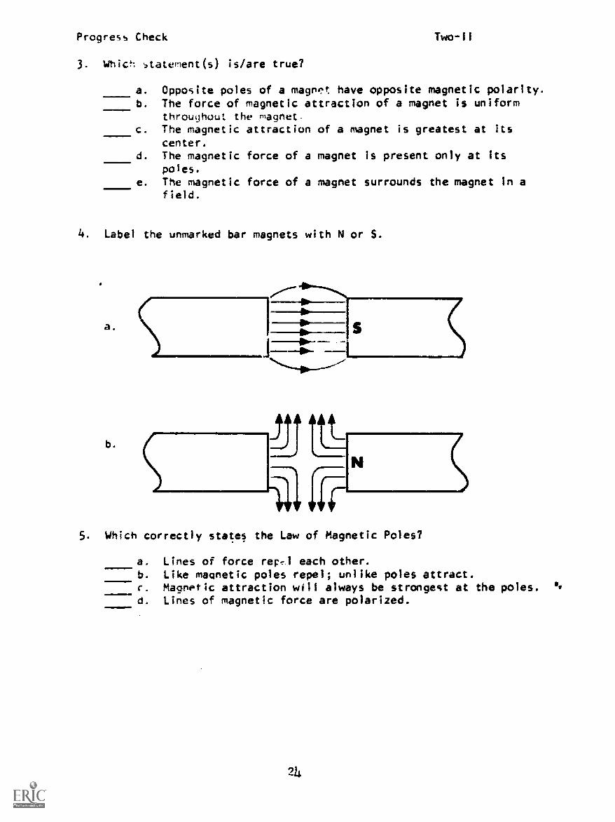
3. Which statevient(s) is/are true?
=m11
a. Opposite poles of a magnet have opposite magnetic polarity.b. The force of magnetic attraction of a magnet is uniform
throughout the magnetc. The magnetic attraction of a magnet is greatest at its
center.d. The magnetic force of a magnet is present only at its
poles.
e. The magnetic force of a magnet surrounds the magnet in afield.
4. Label the unmarked bar magnets with N or S.
a.
b.
S
5. Which correctly states the Law of Magnetic Poles?
a. Lines of force rep.,1 each other.b. Like magnetic poles repel; unlike poles attract.c. Magnetic attraction will always be strongest at the poles.d. Lines of magnetic force are polarized.
214

Progress Check Two-11
6. Which statenient(s) is/are true?
a. The strength of a magnetic field at any point is indicatedA.!by the flux density.
D. Flux density for any magnet is greatest at its poles.c. Flux density increases as distance from the poles increases.d. A strong magnetic field contains few lines of flux.e. The attraction for a piece of iron is strongest where the
flux density is highest.
7. Around a magnet, the external lines of force:
a. leave the magnet from the north pole and enter the southpolP.
b. often cross each other.c. leave the magnet from the south pole and enter the north
pole.d. may be broken by a piece of iron shielding.

Sound/SlideElectromagnetic Induction
Self -Test
III
1. The left-hand rule is used to determine the direction of flowin a generator.
2. When usinq the left-hand rule for generators, the thumb prints in the direc-tion of , and the first finger in the direction of the
The center finger will point in the direction of
3. If the field is moving rather than the conductor, theshould point in the direction of motTag-Fg; conductor.
4. A -agnetic fipld is always visualized as having a direction that is fromto
ionos '43i0u '47 !anoelaJ 4ciLunci3 .E :(Japuo
3eu3 u!) m0 l4 3ua_sin3 4xn,4 JO play 'uo!low JO lsnJul z ula.un, .1
26

Progress Check Two-111
PROGRESS CHECKLESSON III
Electromagnetic Induction
1. Electromagnetic induction is:
a. the process by which magnetism is produced by an electriccurrent flowing through a conductor.
b. the generation of tMF caused by a difference in chargebetween two points.
c. the movement of electrons or current through a conductor.d. the action which causes electron displacement in a con-_
ductor when lines of force move through it.
2. List tha three factors that determine the amount of induced EMF.
1)
2)
3)
3. Which correctly illustrates the Left-Hand Rule for Generators?
.ob. dp
Flux
a.
ELIXTRON
MOVEMENT
ELECTRONNLMENT
flux
27
ELECTRONMOVEMENT
d.
ELLLTRONMOVEALNT
Progress Check
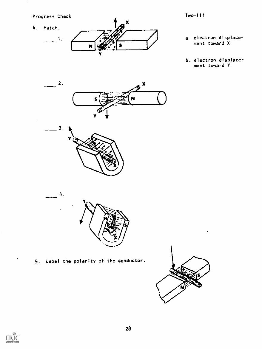
4. Match.
1.
2.
3.
4
5. Label the polarity of the conductor.
Two-111
a. electron displace-ment toward X
b. electron displace-ment toward

Progress Check
6. Electrons will flow from:
a. A to Bb. B to Ac. C to Bd. D to C
Two-III
7. Which statement(s) is/are true?
a. Decreasing the speed of the conductor through the magneticfield results in more EMF.
b. A magnetic field is stronger if the flux density isincreased.
c. If the ctrt.lugch of the magnetic field is increased, EMFwitl decrease.
d. If the number of turns of wire (or loops) in a magneticfield is increased, more EMF results.
e. EMF is greatest when the conductor is moving parallel tothe lines of flux.
29
Progress Check Two-IV
PROGRESS CHECKLESSON IV
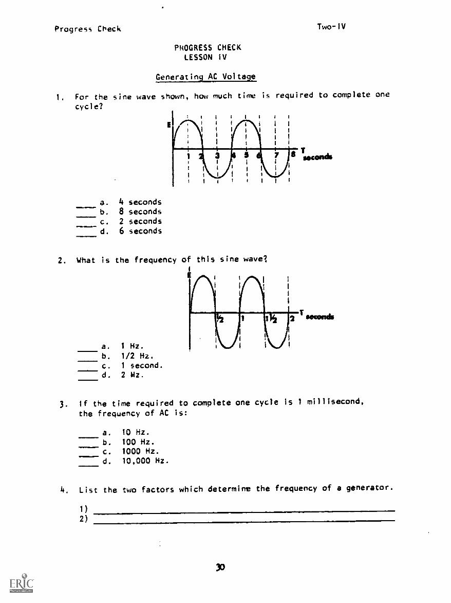
Generating AC Voltage
1. For the sine wave shown, how much time is required to complete one
cycle?1 1 i 1 I I
I 1 1 l I
I I 1 I
I
a. 4 secondsb. 8 secondsc. 2 secondsd. 6 seconds
2. What is the frequency of this sine wave?
a. 1 Hz.
b. 1/2 Hz.
c. 1 second.d. 2 Wz.
2
3. If the time required to complete one cycle is 1 millisecond,
the frequency of AC is:
a. 10 Hz.
b. 100 Hz.
c. 1000 Hz.d. 10,000 Hz.
4. List the two factors which determine the frequency of a generator.
1)2)
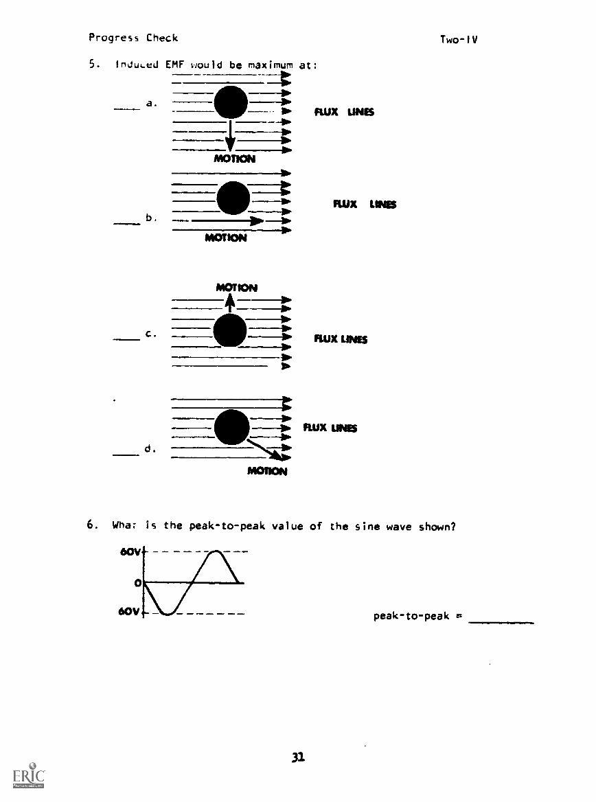
Progress Check Two-IV
5. InduLed EMF would be maximum at:
--1:
a.
b.
c.
d.
III IS FLUX UNES-ew
MOTION
FLUX LOWS
MOTION
MOTION
IFLUX IVIES
1-IN. FLUX LAVES
MOTION
6. What is the peak-to-peak value of the sine wave shown?
0
60V - peak-to-peak e.
31
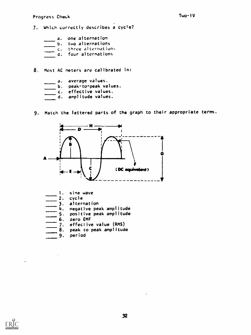
Progress CheLk Two-IV
7. Which correctly describes a cycle?
a. one alternationb. two alternationsc. three alternation.,
O. four alternations
8. Most AC meters are calibrated in:
a. average values.
b. peak-to-peak values.c. effective values.d. amplitude values.11w.
9. Match the lettered parts of the graph to their appropriate terms.
H_soD -Pm
.11INIMINM
F
( DC equivekrnt)
1. sine wave2. cycle3. alternation4. negative peak amplitude5. positive peak amplitude6. zero EMF7. effective value (RMS)8. peak to peak amplitude9. period
32

Progress Check Two-IV
10. Which -,tatement(s) is/are true?
a. The N.nber of cycles per second is called the amplitude.b. The peak value of a sine wave is the maximum positive
or -,axi u. negative value attained during one cycle.c. One cycle of a sine wave is produced each time a simple
AC generator rotates one complete revolution.d. voltage values are usually expressed in effective
values.
11. The symbols used to represent instantaneous values of currentand voltage are:
a. 1, Eb. r, ec. i, ed. i, r
33

Sound/SlideAC-DC Generator Operation
self-Test
module T..o - Le' -,on V
1. List the three requirements for electromagnetic induction to occur.There -us: be:a.
b.
C.
2. A generator is a device used to convert energy intoenergy.
3 An AC generator will have while a DC generator willhave
4 I'- de the wire loops (coils) of either an AC or DC generator, thedirection of current is
constant/changing periodically
5 Draw a graph of the current inside the wire loops (coils) of a generator.
a for 90° rotation 90" 180" 270' 360'
b. for 270 0 rotation0
900 180° 270° 3600
6. The current is maximum at:
00 021 06 0
a. 0, 180 °, and 3600b. 90°c. 90° and 2700
06 0
3 '9
-e .5 Aite3!poped 6ul6uego !(Japio leo
u!) Jolelnuwo e gs6u!) d!is f !(Japio ley u!) te,!J2oata 'teotueoaw -z!(Japi0 tae U!) coLlow aA!lelau 3 s!lau6ew e -q 'Jolanpuo, e -e -t

Progre,., Check Two-V
PROGRESS CHECKLESSON V
of AC and DC
1. Match the lettered parts in the diagram to their appropriatenarles or functionts.
IMM111.111m0
1. armature2. slip rings3. brushes4. rotating loop5. creates lines-of-flux6. magnet
2. Another name for an AC generator is:
...1.1
11111,....11!
a. stator.b. alternator.c. commutator.d. rotor.e. CROW model.
Prugress Check Two-V
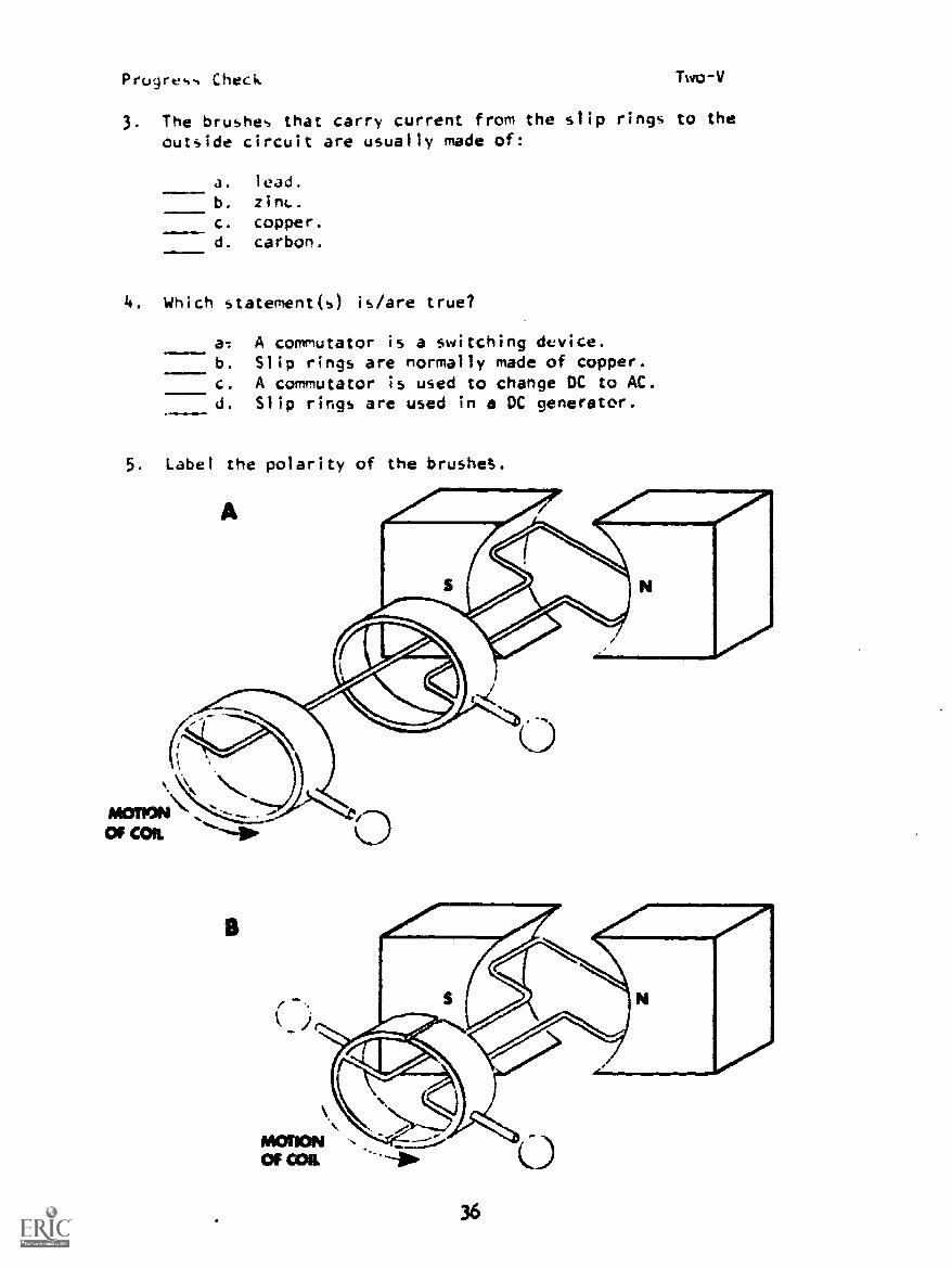
3. The brushes that carry current from the slip rings to theoutside circuit are usually made of
a. lead.
b. zint..
c. copper.d. carbon.
4. Which statement(s) is/are true?
a: A commutator is a switching device.b. Slip rings are normally made of copper.c. A commutator is used to change DC to AC.d. Slip rings are used in a DC generator.
5. Label the polarity of the brushes.
36

Progress Check Two-V
6. W".lch diagram shows the output waveform taken from a commutator?
A. B.
7. Match.
1. usually used for transmission overgreat distances with low loss of
2. the output generated does not varyin direction
3. generator has its contact ringdivided into segments (commutator)
4. generator has .tip ring which trans-mits EMF to the load
5. voltage may be increased or decreasedin value with a low loss of energy
a. AC
b. DC
8. In what position of the commutator would induced EMF bemaximum.
A.
37
B.

Sound/SlideVoltage Measurement - The DC Voltmeter
Self -TestModule Two - Lesson VI
1. When a meter is said to be "polarity sensitive," it makedoes/does not
a difference which lead is connected to the positive or negative side
of the source.
2. DC voltmeters "polarity sensitive."
are/are not
3. The red lead should be connected to the side
of the source. negative/positive/either
4. A voltmeter is connected in with the component across
series/parallelUlrich voltage is to be measured.
5. When measuring the voltage across the load, the voltmeter is connected
so that:
a. all of the current flowing through the load flows through the meter.
b. a small part of the current is passed through the meter.
q S tiatieJed .47 !anoisod !a.te 'z !ssop -t
38

Progress Check Two-VI
PROGRESS CHECKLESSON VI
Measuring Voltage
1. Which schematic shows the voltmeter correctly installed?
A. B. C.
2. To measure DC voltages, a voltmeter must be connected:
a. in series with the load being measured.b. in parallel across the component or source to be measured.c. across a potential difference.d. with its red lead to the negative side of component being
measured and black lead to the positive side.
3. Between what points can voltage be measured?
a. A and Bb. A and Dc. B and Cd. A and Ce. C and Ef. D and E
4. What is the potential difference across the lamp?
1.5V
39
volts

Progress Check
5. Which statement(s) is/are true?
Two-V1
a. Voltage can be measured only -rocs a potential
difference.P. A difference in potential exist. where EMF is generated
and where energy is used by the load.
c. The schematic symbol of a voltmeter is
d. Polarity must be observed when measuring DC voltage.
e. A voltage drop occurs where EMF is generated.f. A voltage rise occurs at the voltage source.
6. To which point in the diagram would the negative terminal of
the voltmeter be connected? (Circle your answer.)
A
I 1
7. What is the total EMF produced by the two batteries?
A H1111} B EMF =
6v 3v
8. What is the potential difference between points A and B?
Ma. 6 voltsb. 4.5 voltsc. 7.5 volts
d. 1.5 volts
9. Complete the table:
Voltage between:
AB BC CD AD
6v 1.5v
ho
B
volts
A D
1----1111 IF-41111-13, 6v
Progress Check Two-111
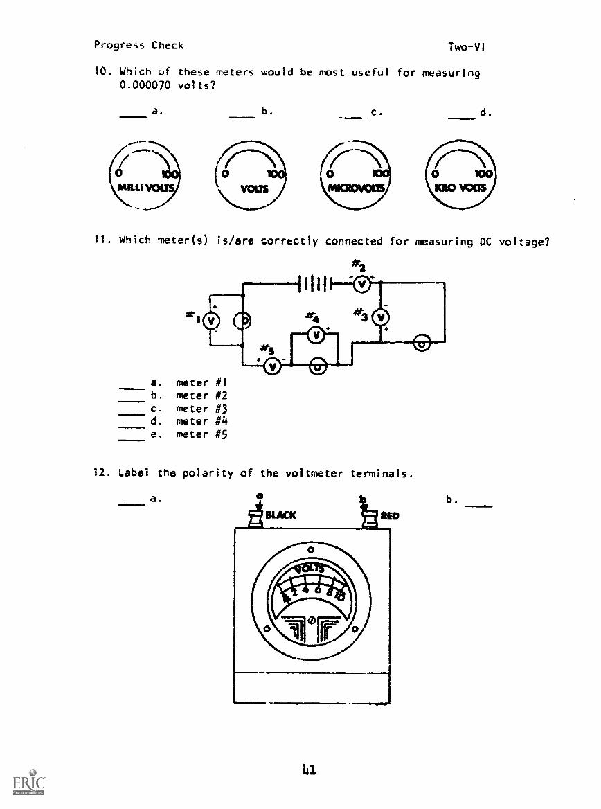
10. Which of these meters would be most useful for measuring0.000070 volts?
a. b. c. d.
11. Which meter(s) is/are correctly connected for measuring DC voltage?
#2
a. meter #1b. meter #2c. meter #3d. meter #4e. meter #5
12. Label the polarity of the voltmeter terminals.
a.
tii
b.

Progress Check Two-V1
13. Using PB 0-1, build a simple circuit according to the schematic below.
Ti T2
TS T7
DS 1
Energize the circuit, then measure and record voltage;a. at the source (between T1 and T8). volts
b. across the load. voltsc. across the closed switch. volts
De-energize the circuit, then measure and record voltage;d. at the source (between T1 and T8). volts.111!..1!e. across the load. volts
f. across the open switch. volts
142

PROGRESS CHECK ANSWERSMODULE TWO
LESSON 1 LESSON 1 (Cont'd)
1. I-d 10. a. 5,000 or 5 x 10³ my
2-a b. 1,000,000 or 1 x 10⁶
..v
3-b c. 4,000 or 4 x 10³
4-e d. 0.004 or 4 x 10⁻³ kv
5-c e. 5 my
2. a f. 3,000 or 3 x 10³ kv
3. a. parallel, 1.5 volts g. 1 v
b. series, 0 volts (opposing) h. 0.000001 or 1 x 10⁻⁶
v
c. series, 4.5 volts (aiding) i. 0.002 or 2 x 10⁻³ my
4. a, b, c j. 30 My
5. a, d k. 0.001 or 1 x 10 -3 my
6. 1-b
2-c
3-a LESSON'll
7. 1-c 1. b
2-c 2. a
3-a 3. a, f
4-a 4. a. N
5-b
8. a. 1 x 10⁻²
v
b. 5 x 10⁻⁶
v
c. 4 x 10³ y
d. 3 x 10⁷ v
9. 1-e
2-d
3-b
4-a
5-e
6-c
7-c
b. N
5. b
6. a. b, e
7. a
LESSON 111
1. d
2. 1) strength of magnetic field
2) speed of relative motion between
conductor and magnetic field
3) length of conductor in magnetic field
3. c

PROGRESS CHECK ANSWERS MODULE TWO
LESSON III (Cont'd)
4. 1-b
1-b
3 -a
4 -b
LESSON IV (Cont'd)
10. b, c, d
11. c
LESSON V
5. 1. 1-B
2 -0
3-C
4-B
6. a 5-A
7. d 6-A
2. b
LESSON IV 3.
1. a 4. a, b
2. a 5. A.
3. c
4. 1) the speed of rotation
of the armature (coil of B.
wire)
2) the number of pairs of
magnet'c poles in the
generator 6. A.
5. a, c 7. 1-a
6. 120 volts 2-b
7. b 3-b
8. 4-a
9. 1-H 5-a
2-0 8. B
3-E
4-C
5-2
6-A
7-F
8-G
9-D

PROGRESS CHECK ANSWERS MODULE TWO
LESSON VI
1. B
2. D,
3. a, c, d, f
4. 0 v
5. a. b, c, d, f
6. A
7. 9 volts
8. b
9.Ail BC Cli '-7Z-1
.....__i
!v i,Iv 3v , 6v
10.
11. a, c
12. a. (-)
b. (+)
13. a. 3 volts (approximate)
b. 3 volts (approximate)
c. zero volts
d. 3 volts (approximate)
e. zero volts
f. 3 volts
IF YOUR ANSWERS ARE ALL CORRECT, TAKE THE MODULE TEST. IF NOT, STUDY
ANY OF THE OTHER RESOURCES AVAILABLE FOR THIS LESSON BEFORE TAKING
THE TEST.

Prugre,,,, Check Three-I
PROGRESS CHECKLESSON I
Characteristics of Resistance
1. List three factors that determine the resistance of a conductor.
(1)
(2)
(3)
2. Which is the poorest conductor?
a. gold
b. copperc. aluminumd. carbone. silver
3. A material is a conductor because:
a. its atoms can easily accept and give up electrons.b. its atoms do not readily accept or give up electrons.
4. Define resistance.
5. The letter abbreviation for resistance is and its unitof measurement symbol Is
6. Which section of copper wire has the most resistance?
a. b. c.
49

Progress Check Three-I
7. Which state-:cnt(s) is/are true?
a. Resistance is a measure of the amount of current flow in aconductor.
b. ,.1! -ater;3I offer ,o-v a,lount of opposition to electronflo.
c. The more resistance a material has, the smaller thecurrent it will conduct.
d. The atomic structure of a material has very little effecton its resistance.
8. 33 k = 33 x 103 = (in basic units).
9. 1.0 x 10³ kilohms equals one
10. Which is true?
a. 500,000 ohms equals 50 Megohms.b. Ohms divided by 1000 equal Megohms.c. Ohms divided by 1000 equal kilohms.d. 0.5 Megohms equals 500 kilohms.
11. If tha length of a conductor is halved, what is the effect on itsresistance?
12. Which section of silver conductor has the least resistance?
a.
5o
b. c.
Progres, Check Three-I
13. Whiol .,tateivot(s) is/are true?
a. The greater the cross-sectional area of a conductor,the smaller the resistance.
b. The oreater the cross-sectional area of a vdire, themighel the re-,istance.
c. An insulator is a material which aids electron flow.d. Rubber, glass, and porcelain are examples of poor
conductors.e. Non-conductors have a low resistance.f. Good insulators have a high resistance.g. The unit of measure for resistance is the ampere.
If you don't know what it does don't fool with it!
51
Progress Check Three-11
PROGRESS CHECKLESSON 11
Resistors
1. Resistors are usually classified according to:
a. the materials used for their resistance elements.b. their ohmic value or amount of resistance they possess.
c. whether their resistance value is fixed or can be
varied.d. their physical size.
2. Which statememt(s) isiare true?
a. The value of a fixed resistor is set and cannot be varied.b. Potentiometers and rheostats are classified as fixed
resistors.
c. More than one resistance value can be obtained from atapped resistor; however, each of these values is fixed.
d. The maximum resistance value of a tapped resistor dependson the number of taps or connections that it has.
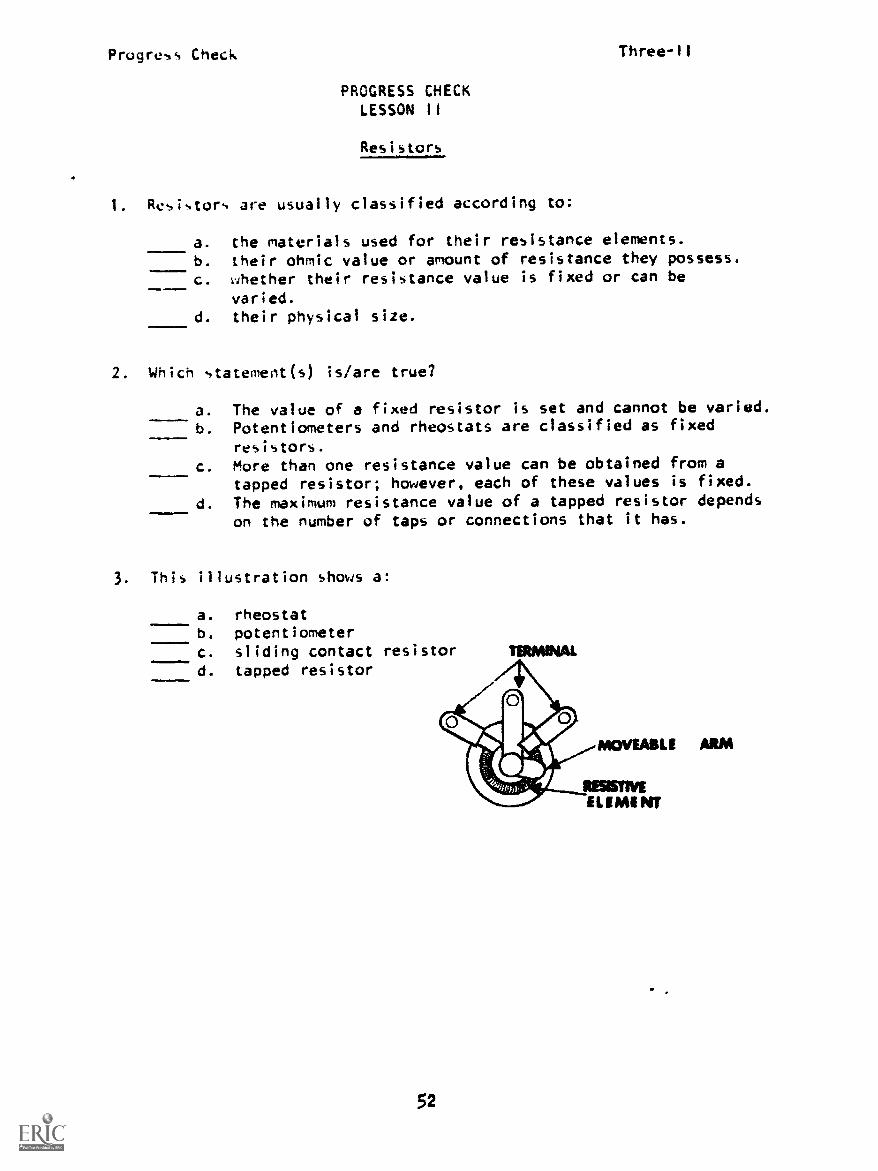
3. This illustration shows a!
=.
a. rheostatb. potentiometerc. sliding contact resistord. tapped resistor
52
ISIMINAL

Progress Check
4. WhiLh Lircuit ;how, a rheostat?
A.
53

Progress Check Three-II
5. Draw the schematic symbol for each of the resistors illustrated.
a.
b.
c.
d.
e.
f.
..100.=1.1!

Progress Check Three-11
6. MatLh.
1. inexpensive and easy tomanufacture
2. ohmic value-, tend to changewith age
3. e) .ensive to manufacture4. able to carry large amounts
of current without damage5. low current handling capabilities6. highly accurate resistance values7. ohmic values not highly accurate;
wide tolerance range8. resistance values very stable
over long periods of time
7. Which statement(s) is/are true?
a. carbon resistors
b. wire-wound resistors
a. Resistor value refers to the number of ohms of resistancea resistor ha4
b. Resistance is a physical property.c. it is possible to tell the resistance value of a resistor
from its physical size.d. Resistors with greater cross-sectional area have gleaner
resistance.
8. Which resistor has the most resistance?
a.
b.
c.
d.

Progress Check Three-11
9. The wattacje rating of a resistor:
a. determines a resistors ohmic value.b. determines the maximum current a resistor can safely carry.
c. refers to the amount of resistance possessed by a resistor.d. is determined by the resistor's physical size.
10. Match.
1. highest ohmic value a. (7201
2. highest wattage rating
b. CUDOCCOMA-
c.
d.
11. In which circuit would the lamp burn brightest?
a.
r_
b.
56
2 X10...K :.. ;f Dorm, ..em
c.
Progress Check Three-Ill
PROGRESS CHECKLESSON III
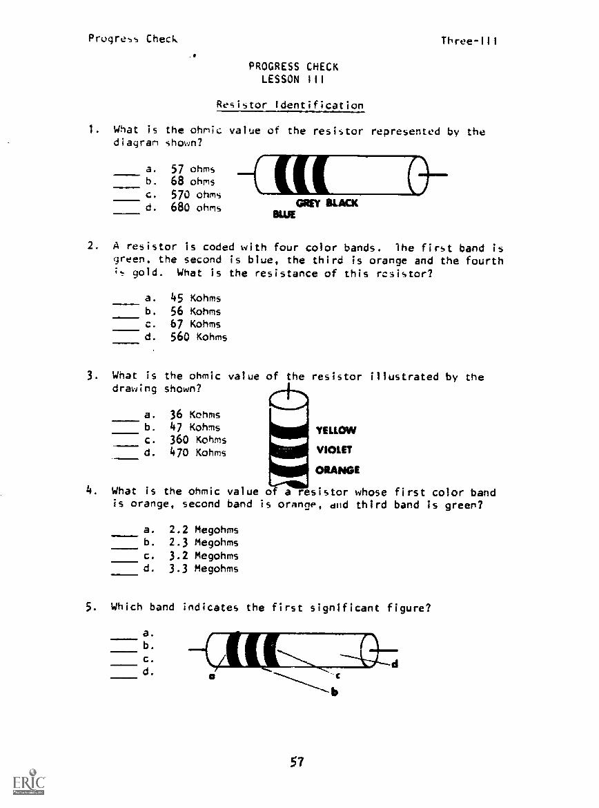
Resistor Identification
1. What is the ohmic value of the resistor represented by thediagram shown?...,, a. 57 ohms
b. 68 ohmsc. 570 ohmsd. 680 ohms
BLUEGREY BLACK
2. A resistor is coded with four color bands. the first band isgreen, the second is blue, the third is orange and the fourthit gold. What is the resistance of this rcsistor?
=11MIMm.
a. 45 Kohmsb. 56 Kohmsc. 67 Kohmsd. 560 Kohms
3. What is the ohmic value of the resistor illustrated by thedrawing shown?
=..a.VINNIa. 36 Kohmsb. 47 Kohmsc. 360 Kohmsd. 470 Kohms
YELLOW
VIOLET
ORANGE
4. What is the ohmic value of a resistor whose first color bandis orange, second band is orange, dfld third band is green?
1111 a. 2.2 Megohmsb. 2.3 Megohmsc. 3.2 Megohmsd. 3.3 Megohms
5. Which band indicates the first significant figure?
1/1.1 a.
--(/ (.1[,I:
a
57

Progress Check Three-111
6. The tolerance of this resistor is:
....111am a. 1
b. 5.
c. 10
d. 20 SILVER
ORANGE
--REDYELLOW
7. Which is the correct sequence of color bands on a 24 Kohm resistorvrith a tolerance of 10,:?
a. yellow, red, orange, silver.b. silver, red, yellow, orange.c. red, yellow, orange, gold.d. red, yellow, orange, silver.
8. Color band "b" on the resistor below indicates the:
a. first significant figureb. second significant figurec. multiplierd. tolerance
9. What is the resistance of the resistor illustrated in figure #1?
a. 5.63 ohmsb. 56 kohmsc. 56.3 ohmsd. 563 ohms
RC4201563.1
10. What is the magnitude of resistance offered by a resistor thathas the designation "RC220104K"?
a. 100 kohmsb. 10 kohmsc. 10.4 kohmsd. 22.1 kohms
11. What is the resistance of this resistor?
Is!?!C. 47.5 ohms
a. 475 kohmsb. 4.7 megohms
d. 475 ohms
RN6 011475 F
58

Progress Check Three-IV
PROGEESS CHECKLESSON IV
The Ohmmeter
1. The principle function of an ohmmeter is to measure themagnitude of:
a. currentb. resistancec. voltaged. conductance
2. In the schematic shown, which ohmmeter will indicate the resistanceof resistor B?
a. 01
b. 02
c. z3
d. ale
3. On the diagram shown, an ohmmeter must.be connected betweenpoints to measure the combined resistance ofresistors A and B.
a. 1 and 4C B Ab. 2 and 3 ---\AA: --vv\v------,\Ajv
c. 2 and 41 2 3 4d. 1 ana 3
4. When resistance is measured using the ohms function of a multi-meter, minimum resistance values will be indicated when the meterpointer is at the portion of the ohms scale.
a. linear portionb. extreme leftc. extreme rightd. center
5. When res;stace is measured with a multimeter, the scaleis svch that maximum resistance is indicated at the
a. extreme rightb. extreme leftc. linear portiond. center
59

Progress Check Three-IV
6. When measuring a 100 Kohm resistor, the pointer on the ohmmeter
scale indicates 10. in what position is the range selector?
mrsam.re..
a. R x 10b. R x 100c. R x 1,000d. R x 10,000
7. What will the pointer indicate on an Ohmmeter scale if the range
selector is set to R x 10,000 and the resistor being measured is
5.6 Megohms/
a. 0.56b. 5.6c. 56d. 560-,.-
8. The pointer of an ohmmeter indicating mid-scale, with the range
selector in the R x 100 position, will when the
range selector is moved to the R x 10,000 position.
a. move toward infinityb. not movec. move toward zero
6(0

PROGRESS CHECK ANSWERS
MODULE THREE
LESSON I
1. (1) type of material used
(atomic structure of a
material)
(2) length of conductor
(3) cross-sectional area
of conductor
LESSON (Cont'd)
5. a.
b. -WV-
c'
d. -^/0"-
e. _AAA
f. -"/VP--
2. d 6 1. a
3. a 2. a
4. Resistance is the property 3. b
of a material that opposes 4. b
current flow. 5. a
5. R. - 6. b
6. b 7. a
7. b, c 8. b
8. 33.000_ 7. a, b
9. megohm 8. c
10. c, d 9. b, d
11. Resistance will be halved 10. 1. d
12. a 2. c
13. a, d, f 11. c
LESSON if
1. a, c
2. a, c
3. b
4. B
LESSON III
1. b
2. b
3. b
4. d
61

PROGRESS CHECK ANSWERS MODULE THREE
LESSON III (Cont'd)
5. a
6. c
7. d
8. b
9. b
10. a
11. b
LESSON IV
1.
2.
3.
4. c
5. b
6. d
7. 0-
8. c
IF YOUR ANSWERS ARE ALL CORRECT, YOU MAY TAKE THE MODULE TEST. IF
NOT, STUDY ANY OF THE OTHER RESOURCES AVAILABLE FOR THIS LESSON BEFORE
TAKING THE PROGRESS CHECK AGAIN.
62
Progre.,s Check
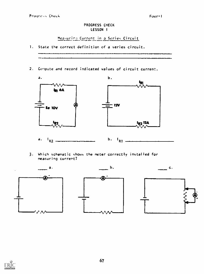
PROGRESS CHECKLESSON 1
measuriri Current in a Series Circuit
1. State the correct definition of a series circuit.
Four-f
2. Cornpute and record indicated values of circuit current.
a.
a. 1
R2
b.
b. 1
R1
3. Which schematic shows the meter correctly installed formeasuring current?
a. b.
67
c.

Proqre,,, Check Four-1
4. match the sche-iatiLs to their appropriate characteristics.
c.
b.
d.
1. more than Line path for current flow
2. series circuit3. parallel circuit4. only one path for current flow
5 To measure direct current on any scale, except the 50 microamp scale, the meter function switch must be in the
position.
6. Which illustration indicates a current value of 20 .amps?
a. b.
IMMA
SOVPa
66

Progress Check Four-1
7. Using FractIce Board 0-1. a 62 k resistor, and one dry cell,construct a series circuit as indicated by the schematic andclose the switch, then measure and record circuit current.
8. What is the current reading indicated below?. a. 40 mab. 430 mac. 230 mad. 80 ma
69

Progress Check Four-I
9. On the illustration below, check the arrows which point to thejacks used when making current measurements in the ranges of0-1 ma, 10 ma, 100 ma, 500 ma.
10. Modify the series circuit you constructed for question #7 asshown below and close the switch, then measure and recordcircuit current.
70

Four-11
PROGRESS CHECKLESSON 11
Voltage in a Serie. Circuit
1. Stud.. the ,c_he.atic. then check the statement(ti) that is/are true.
. 4V
fin 4-
5V
a. The voltage rise is equal to the sum of the voltage drops.b. The total voltage dropped is 13 volts.c. The voltage drop across RI is greater than the voltage
drop across R2.d. The voltage rise at the source is 4 volts.e. The total applied voltage is i8 volts.f. The rise in potential is 9 volts.
g. The polarities indicated for both voltage drops are correct.h. The polarity indicated for ER1 is correct.
2. Select the resistor in each schematic that will have the largestvoltage drop.
a.
71
b.

Progre.,, Check Four-11
3. Match letter...d arrows on schematic to corresponding voltageconcepts. -A
1. voltage rise2. "0" difference in potential3. voltage drop
4. Compute and record the correct amount of total voltage rise ordrop in each schematic.
ER1 3V
a.
b.
Ea
6.5V
ER3 2V
fR2 L5V
72
voltage drop
voltage rise

Progre,, Check Four-If
5. Co -cute and record the ,ource voltage (Ea
a.
b.
ER2 25V
73
in each ,chematic.
Ea =
Ea
=

ProgreNs Check Four-Ill
1. Match.
2.
3
4
PROGRESS CHECKLESSON III
The Multimeter as a Voltmeter
a. AC voltage meterconnection
b. DC voltage meterconnection
c. incorrect voltmeterconnection (AC or DC)

Progress Check Four-III
2. Check the -,tatementW that is/are true.
a. When measuring voltage with a multimeter, the functionsitch ntiSt alway., be in the +DC position.
b. When reatiing DC voltage, polarity must be observed.c. When measuring DC voltage with a multimeter, correct
meter connection will cause pointer deflection to theleft of zero.
d. Meter polarity of the Simpson 260 can be changed bymoving the function switch to either +DC or -DC.
e. Meter polarity of the Simpson 260 can only be changedby removing the test leads from the circuit and reversingthem.
3. Interpret the meter DC scale below by matching the indicatedvoltage to the range switch position.
U0I520 30
4 6
Range-Switch Position
1. 10 v2. 50 v3. 2.5 v4. 250 v5. 1000 v
mImFO
75
406
DC Voltage
a. 540 voltsb. 135 voltsc. 27 voltsd. 1.35 voltse. 5.4 volts

Pruyre.- Cht.Lk Four-Ill
4. Check the lettered parts and scales of the multimeter that are used
for fieasuring DC voltage.
UST COPY AVAILABLE
76

Progress Checl, Four-lit
5. The diagram below illustrates a circuit with a variable resistor,a fed resistor, and a source connected in series. The variableresistor is shown at three different settings.
Check the statement(s) that is/are true.
a. The largest voltage drop will take place across the leastresistance.
b. The voltage drop across the variable resistor is alwaysgreatest.
c. The voltage drop across the variable resistor will becomegreater or smaller as the resistance goes up or down.
d. The voltage dropped across a fixed resistor always remainsthe same.
e. The sum of the voltage drops always equals the appliedvoltage.
77
Progrt.,, Check Four-111
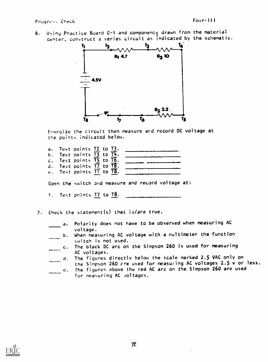
6. Using Practice Board 0-1 and components drawn from the material
center, construct a series circuit as indicated by the schematic.
tj
4.5V
Ts
Ehergize the circuit then measure and record DC voltage atthe points indicated below.
a. Test points T2
b. Test points T3
c. Test points T5
d. Test points T7e. Test points T1
to T3.
to i.to T.to Tom.
to IT
Open the switch and measure and record voltage at:
f. Test points 17 to T8.
7. Check the statement(s) that is/are true.'
a. Polarity does not have to be observed when measuring ACvoltage.
b. When measuring AC voltage with a multimeter the function
switch is not used.c. The black DC arc on the Simpson 260 is used for measuring
AC voltages.d. The figures directly below the scale marked 2.5 VAC only on
the Simpson 260 ere used for measuring AC voltages 2.5 v or less.
c. fhe figures above the red AC arc on the Simpson 260 are used
for measuring AC doltages.

Progr .,-. Check Four-Ill
8. Interpret the meter reading and record the Indicated AC voltagefor each range switcn position.
Range Switch Position Meter Reading
a. 10 vb. 50 vc. 2.5 vd. 250 ve. 1000 v
LEST COPY AVAILABLE
79
volts ACvolts ACvolts ACvolts ACvolts AC

PROGRESS CHECK ANSWERS
MODULE FOUR
LESSON I LESSON II (Cont'cll
1. Only one path for current 5. a. 35 v
flow. b. 55 v
2. a. 6 amps
b. 12 amps LESSON III
3. a 1. 1. b
4. 1-b and d 2. a
2-a and c 3. c
3-b and d 4. a
4-a and c 2. b, d
5. +0C or -DC 3. 1. e
6. a 2. c
7. Approximately 25 .amps 3. d
8. b 4. b
9. c, e 5. a
10. Approximately 250 milliamps 4. b, e, f,
5.
LESSON II 6.
1. a, c, f, g, h
2. a. R1
b. RI
3. 1. a
2. b and d
3. c
4. a. 6.5 v (drop)
b. 3 v (rise)
c, e
Approximately
a. 1.25 v
b. 2.6 v
c. 0.6 v
0. 0 v
e. 4.5 v
f. 4.5 v
7. a, d, e
8. a. 7.5 VAC
b. 37.5 VAC
c. 1.9 VAC
J. 187.5 VAC
e. 750 VAC

PP.QGPEY:. LHECK ,ANSWERS MODULE FOUR
iF YOUR AuMRS ARE ALL CORRECT, YOU MAY TAKE THE MODULE TEST. IF NOT,
STULY ANY OF THE OTHER RESOURCES AVAILABLE FOR THIS LESSON BEFORE TAKING
THE PROGRESS CHECK AGAIN.
POOR SHOT-.1 :*
N "lb %
;POtIR tLins.HOUSEKEEPING

C!'et.:k Five-I
PROGRESS CHECKLESSON
V,:ltale. Current, and Resistance
1 r, circuit tnat unk one path for current fIcycJ itia/a7 circuit.
a. oderb. .,eriet,
:. stuart
d. parallel
I' circuit resistance is physically changed to a higher value,drd the applied voltage remains unchanged, circuit current will:
a. increase.
b. decrease.c. remain the same.
d. increase by the square.
3. Wnat is the value of ERI
in the diacaran.*,hown below?
a. 180 v100 v
c. 80 rJ. 20 v
ER320V
60V
4. If the value of voltage applied to a circuit is physicallydoubled :Thiie circuit resistance is unchanged, circuit current
a. decrease by four times.. double.
C. rerain the same.d. increase by four times.
e7
Progress Checl Five-1
5. P,,N,i,111. re.dtruing a circuits applied voltage to half of its
original value cause the circuit current to be:
a. halved.
c. tripled.
a. quadrupled.
6. Mu .,tatu-era, "Circuit current is directly proportional tothe applied voltage and inversely proportional to circuit re-sistance," is knopel as:
d. Kifchhoff's Lap..
b. Joule's Lay..
c. Ohm's Law.d. Weber's Theory.
7. Pn.rsically decreasing circuit resistance will cause circuitcurrent to:
a. increase by square.b. decrease.c. increase.
d. re,,ain unchanged.
86

Prugress Check Five-11
PROGRESS CHECKLESSON 11
Ohm's Law Formula
1. Converting chemical energy to electrical energy within a sourcedescribes a:
a. fall in potential.b. rise in potential.c. voltage drop.d. power transfer.
2. Wi,at is the value of the voltage drop across a 30-ohm resistort''at has 2 amps of current flowing through it?
a. 0.06 voltsb. 15 voltsc. 60 voltsd. 120 vo.ts
3. What is the value of current?
a. 1.66 -la
b. 16.6 maC. 166 mad. 1.66 a
4. What i the value of the load resistance?
a. 300 ohmsb. 480 ohmsc. 30 kohmsd. 48 kohris
89

Fl fe., Checl. Five-11
5. wwt is the vultage drop acro,-, a 1 kohm resistor that has
2 -ma of current flo,.ing through it?
a. v
b. ..: .v
C. A. V
d. 0.5 My
6. Which of the follovAny mathematically expresses Ohm's Law?
a. 1 =
b. P IE
4. W = FD
P=
7. Which of the following accurately describes the conversion fromelectrical energy to heat energy within a resistance?
a. voltage dropb. current lossc. rise in potentialJ. po.ier loss
8. What Is the value of source voltage in the circuit diagramsOlbr1 be1j.,:7
a. 6 4b. 8 vc. 12 v
d. 24 V
RI 2K
I.72nta
L.R3 6K
90
R2 4K

Proyress Check Five-11
9. 50 c4:p1;0'd ArrC,',S a resistor, causes 5 amps of currentto flow. What is the value of the resistor?
e.
a. 10 ohms.b. 25 uh is.
c. 250 uhm.d. 2.5 kohms.
10. What is the value of total current in the diagram below?
a. 2 mab. 5 mac. 2 ad. 5 a
11. What is the value of current flow if a 40-ohm resistor isconnected across a 20-volt battery?
a. 0.2 ab. 0.5ac. 2 ad. 5 a
12. What is the value of the load resistor in the diagram shownbelow?
a. 10 ohms.b. 100 ohms.c. 1 kohm.d. 10 kohms.
al0ma
91

Progress Check
13. Which of the following is a characteristic of the circuit
represented by the diagram shown?
a. V(Otage drop% are equal.
b. Total resi-tanLekhan the smallest resistor.
c. Total current is the sum of
individual currents.d. Total resistance is greater
than the largest. resistor.
14. What is the resistance of R3?
a. 8 ohmsb. 12 ohms
c. 18 ohmsd. 20 ohms
15. What is the value of RT?
a. 765 kohms
b. 15.5 kohms
c. 15.75 kohmsd. 765 Kohms
RI
92
250 f2

Progress Check Five-III
PROGRESS CHECKLESSON III
Power
1. The amount of work done per unit time describes:
a. current.b. voltage.c. resistance.d. power.
2. How much power is dissipated by a circuit that has a 75-voltsource and a current flow of 5 ma?
a. 375 wb. 3.75 wc. 0.375 wd. 37.5 w
3. Which of the following correctly expresses the relationshipthat exists between power, work and time?
a. P =
b. P =
c. P=WxTd. P = W + T
4. In the circuit represented by the diagram below, how muchpower is supplied by the source?
a. 6.15 wb. 16.6 wc. 110 w
d. 160 w 11SbW
93
Pi 20W
Progre-,, Cheek
5. Electrical power can be expressed as:
a. force per unit area.b. co,i1umbs per unit time.
c. work per unit t ire.
d. joules per coulomb.
Five-111
6. How much power is dissipated by a circuit that has a 440-volt
source and a total resistance of 880 ohms?
a. 110 w
b. 220 wc. 440 wJ. 880 w
7. How much power is dissipated by a circuit containing 6 K ohms
of resistance when 2 ma of current is flowing?
a. 2.4 mwb. 24 mwc. 1.2 w
d. 12 w
94

Progress Check Five-IV
PROGRESS CHECKLESSON IV
Internal Resistance
1. When a load is placed across a source, what causes the decreasein terminal voltage?
a. the internal resistance of the source.b. the physical size of the source.L. the power dissipated by the load.d. the physical size of the load resistance.
2. Internal resistance is an opposition to current and willLause voltage to be present across the load.
more/less
3 A!, circuit current increases, the voltage drop across theinternal resistance will
increase/decrease
4. 1-creasing the load resistance will result in circuitmore/less
current and therefore voltage dropped across the internalresistance. more/less
5. All sources of EMF contain a certain amount of resistance.This opposition to current flow is called:
a. terminal resistance.b. internal resistance.c. load resistance.d. circuit resistance.
6. Internal resistance of a source be measured withan ohmmeter. can cannot
95

Progress Check
PROGRESS CHECKLESSON V
Treubleshootin3 Series Circuits
1. A shorted curponent in a series circuit willtotal resistance.
a. cause an increase inb. cause a decrease inc. have no effect ond. always double
Five-V
2. What effect will an open have on total resistance of a seriescircuit?
a. Total resistance will increase to infinity.b. Total resistance will always double.
c. Total resistance will always decrease to zero.d. Total resistance will decrease to a smaller value.
In a series circuit a shorted component will cause:
a. a decrease in circuit currentb. an increase in total resistancec. a decrease in all voltage dropsd. an increase in circuit current
4. In the circuit represented by the diagram shown, a short acrossR-3 will cause i /an.
a. increase in totalresistance.
b. decrease in totalcircuit current.
c. decrease in the voltagedrops across ER1 and E
R2.
d. increase in the voltaged..-ps across ER1 and E
R2.
96

Progres, Check Five-V
S. What vtieLt dues an open have on circuit current?
a. It will cause current to decrease to 0.b. It will cause current to exactly double.
lt -ill ,au,ft Lurrynt to increase at a linear rate.d. It will cause current to decrease to half its original
value.
6. Determine the trouble in the circuit represented by the diagram3hown by comparing the abnormal with the normal measurements.
NORMAL CIRCUIT ABNORMAL CIRCUITa. point A grounded MEASUREMENTS MEASUREMENTSb. RI openc. R3 open E 200 v 200 vd. point B grounded MI 50 v 0
M2 10 ma 0M3 150 v 200 v
97

LESSON I
PROGRESS CHECK ANSWERS
MODULE FIVE
LESSON III
1. b 1. d
b 2. c
3. d 3. a
4. b 4. c
5. a 5. c
6. c 6. b
7. c 7. b
LESSON II LESSON IV
1. b 1. a
2. c 2. less
3. c 3. increase
4. c 4. less; less
5. c 5. b
6. a 6. cannot
7. a
8. d LESSON V
9. a 1. b
10. a 2. a
11. 5 3. d
12. d 4. d
13. d 5. a
14. a 6. c
15. c
IF YOUR ANSWERS ARE ALL CORRECT, YOU MAY TAKE THE MODULE TEST. STUDY
ANY OF THE OTHER RESOURCES AVAILABLE FOR THIS LESSON BEFORE TAKING THE
PROGRESS CHECK AGAIN.

Pr,,,gress Check Six-I
PROGRESS CHECKLESSON I
Rutes for Voltage and Current
1. A parallel circuit is one in which:
a. the currents through each branch are equal.b. there is more than une current path connected to a common
voltage source.c. the vo:tagu drops across each component are different.d. there :5 only one path for current flow.
2. Which statement below expresses the relationship between sourcevoltage and the voltage drops across each branch of a parallelcircuit?
a. Sour Rage increases as any branch voltage dropdetrt.oss.
b. The voltage drop across each branch is equal to sourcevoltage.
c. The voltage drop across each branch increases as thesource voltage decreases.
d. Source voltage is the sum of the voltage drops acrosseach branch.
3. Which of the following equations is the mathematical expressionfor total voltage in a parallel circuit?
11!0
a . ET = El x E2 x x En
b. ET = El + E2 + + En
c. ET = El = E2 = =En
- 1
d.I
= - - En
4. Which of the following equations would be used to determinetotal current in a parallel circuit?
a. fir = 1
112 1
2= = I
n- I
b. 1T = 11 - 12 - - 1-- I
c. IT = 1
1+ 1
2+ + I
n
d. IT = 11 x 12 x x In
103

Progress Check Six-I
5. In a parallel circuit, current through each branch is inverselyproportional to:
a. the number of branches.b. the source voltage.c. total circuit current.d. the branch resistance.Mi.
6. Between what two points of the circuit represented by this dia-gram should an ammeter be inserted to measure total circuit current?
a. A and Bb. C and Dc. D and Ed. E and F
A B
7. When R3 is added to the circuit diagram shown below, the currentthrough R1 will:
a. in:A-ease.
b. decreacr by half.c the square.
!_t aAr-34'
8. In t p sente1 by the diagram shown below, betweenre-r
v!hat !nts 7.hoL.41 en ammeter be inserted to measure the
ccmbi:e: cusr_nts of R2 and igy
a L
E
c C rr D
d. A and B
1014

Progress Check Six-1
9. What happen to the total current in a parallel circuit whenanother resistor is connected in parallel?
a. Current will always triple.b. Current -ill decrease.
c. Current will not change.d. Current will increase.
10. In the circuit represented by the schematic shown below, betweenwhat two points would a fuse be placed to protect all circuitcomponents?
a. A and Bb. C and 0c. E and Fd. G and H
A B
11. In the circuit represented by the diagram shown below, if 52 isopened, the voltmeter reading will:
a. increase.
b. decrease.c. drop to zero.d. remain steady.
105

Progress, Check
PROGRESS CHECKLESSON II
Rules for Resistance and Power
I. In the' circuit below, it resistor R2 is replaced with one of greaterreNi-,tanCes the:
a. total circuit resistance will decrease.b. current flow through RI will increase.L. voltage drop across R2 will increase.d. power dissipated by RI will remain the same.
12. WsiCh of the follo :ng equations is used to determine the total
r,istance of a two-branch parallel circuit?
a. RT = RI R2---
b. RT
RI + R2
RI x R2c . R =
T RI + R2
d. RT
RI + R2RI x R2
3. in the circuit represented by the diagram shown, if RI is
Ji..connected from the circuit, the indication on ohmmeterM1 will:
a. increase.
U. decrease.c. drop to O.U. increase to infinity.
106

Prugr,, CheLk Six-I1
4. 14 a third current path is added to a two-branch parallel circuit,the total resistance of the circuit will be:
a. thar it tw.1, before the current path was added.L. ;realer than it ..a before the current path WdS added.c. the sa-e as it was before the current path was added.d. equal to the resistance of the additional current path.
5. Which of the following expressions could be used to determine thetotal resistance of a parallel circuit containing resistors ofe.ual value?
a. RT n
RI x R2b. R =
RI x R2
RI + R2c R
T RI + R2
RI + R2d R
T
6. Which of the following expressions could be used to solve fortotal power of a parallel circuit when the power dissipated byeach branch resistor is known?
a. P, = I
2ET
b. PT
= P1
P2
+ + P
c. PT
= 12
Ix P2 x x P
d. PT
seP
107

PrUlt-V,Is ChtCI.
7. Which cf Ih beiu- re,iturs hd., the same resistance as theequivalent resistance of RI and R2?
(ANILBrownYell
Red
BrowPlack
Yellow HrownGreyYe! low
cf.
Brow orangeGreen
8. 1.rhic4 of the following describ-s the relationship between theequivalent resistance and the individual branch resistance of
a parallel circuit? Equivalent resistance will always be:
a. qreater than the largest branch resistance.
b. smaller than the smallest branch resistance.
c. equal to the sum of the branch resistance.J. equal to the .,real lest branch resistance.
9. In the circuit represented by the diagram shown below, what will
happen to the equivalent resistance when R3 is connected?
J. ncreaseb. decrea-,e
c. doubled. not change R1 RZ 3
108

Progress Check Six-II
10. In the circuit diagram shown below. the total power dissipatedb the circuit when R3 is connected will:
a. double.q0t 4t'd'
C. increase.d. decrease.
-
R1141R2
11. In a three-branch parallel circuit, the equivalent resistanceof any two of the branches will always be:
a. the same as the total resistance of the circuit.b. less than the total resistance of the circuit.c. greater than the total resistance of the circuit.d. equal to the equivalent resistance of any other two
branches.
12. A circuit consists of two resistors, equal in ohmic value, con-nected in parallel. What is the total resistance?
a. oi.e-half the value of one resistorb. one-half the sum of the resistorsc. the sum of the resistorsd. the same as the value of one resistor
13. What is the value of the equivalent resistance of a three-branchparallel circuit that contains resistors of 20 ohms, 30 ohms,and 60 ohms?
=11m. a. 0.1
b. 0.6c. 10.
d. 110..
109
Progress Check Six-III
PROGRESS CHECKLESSON III
Variational Analysis
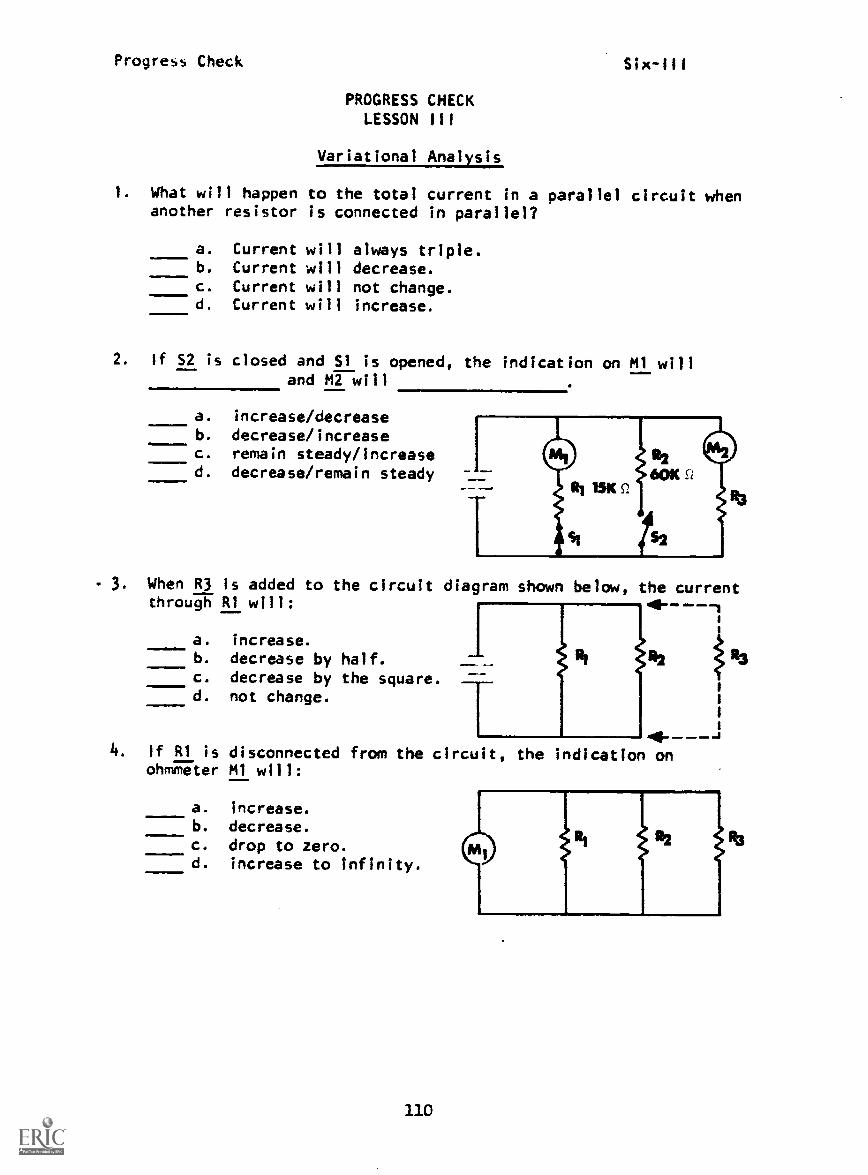
. What will happen to the total current in a parallel circuit whenanother resistor is connected in parallel?
a. Current will always triple.b. Current will decrease.c. Current will not change.d. Current will increase.
2. If S2 is closed and Si is opened, the indication on M1 willand M2 will
a. increase/decreaseb. decrease/increasec. remain steady/increased. decrease/remain steady
- 3. When R3 is added to the circuit diagram shown below, the currentthrough 111 will:
a. increase.b. decrease by half.c. decrease by the square.d. not change.
4 - - --J4. If R1 is disconnected from the circuit, the indication on
ohmmeter M1 will:
22
a. increase.b. decrease.c. drop to zero.d. increase to infinity.
1.10

Progress CheckSix -Ill
5. If resistor R2 is increased in value, which of the followingis correct?
a. Total circuit resistance will decrease.b. The current flow through RI will increase.c. The voltage drop across RIwill increase.d. The power dissipated by ill will remain the same.
6. What will happen to the equivalent resistance when R3 isconnected?
a. increaseb. decreasec. double
7. The total power dissipated when R3 is connected will:
10 a. double.b. not change.c. increase.d. decrease.
8. What effect will an open in one branch of a parallel circuit haveon total circuit current?
a. An open will cause circuit current to increase.b. An open will cause circuit current to double.c. An open will cause circuit current to decrease.d. An open does not effect circuit current.
Ui

Progress Check
9. Decreasing source voltage will cause I
R3to:
a. remain constant.b. increase.c. decrease.d. stop.
10. Increasing E in a parallel circuit causes the current through eachbranch to proportionally.
112
Progress CheckSix-IV
PROGRESS CHECKLESSON IV
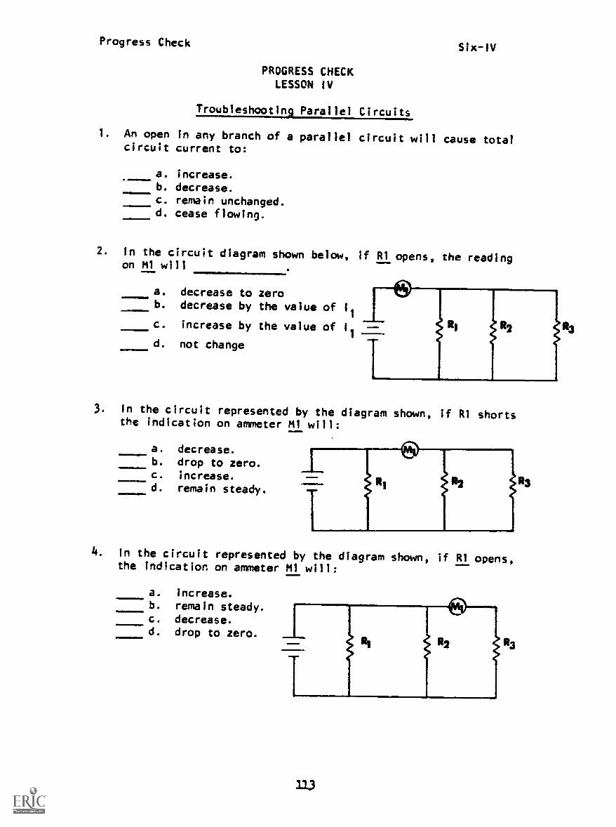
Troubleshooting Parallel Circuits
I. An open in any branch of a parallel circuit will cause totalcircuit current to:
a. increase.MININNINMAIn
MIM
b. decrease.c. remain unchanged.d. cease flowing.
2. In the circuit diagram shown below, if RI opens, the readingon MI will
a. decrease to zerob. decrease by the value of 11
c. increase by the value of --
d. not change
3. In the circuit represented by the diagram shown, if Rl shortsthe indication on ammeter Ml will:
a. decrease.b. drop to zero.c. increase.d. remain steady.
4. In the circuit represented by the diagram shown, if RI opens,the Indication on ammeter Ml will:
a. increase.b. remain steady.c. decrease.d. drop to zero. L
113

Progress Check Six-IV
5. In the circuit diagram shown below, if R2 opens, what valueof current will flow through R4?
a. 0
b. 6 mac. 8 mad. 12 ma
6. An open in any branch of a parallel circuit will:
a. have no effect on any other branch.4. cause total circuit current to increase.c. decrease total resistance.d. Increase the power supplied to the circuit.
7. By comparing abnormal with normal measurements, rmine thetrouble in the circuit represented by the diagram.
111.1
NORMAL CIRCUIT ABNORMAL CIRCUITa. open at point A MEASUREMENTS MUSUREMENTS
b. 111 open
c. R2 open
d. R3 open
Ea
30 v
Ml 6 ma
M2 3 ma
M3 3 ma
30 v
5 ma
3 ma
2 ma

Progress Check Six-IV
8. By comparing the abnormal with the normal measurements, determinethe trouble in the circuit represented by the diagram.
MOMM1
a.
b.
C.
point A open
point B open
point C open
d. point D open
NORMAL CIRCUIT ABNORMAL CIRCUITMEASUREMENTS MEASUREMENTS
Ea
50 v
M1 50 v
M2 8 ma
M3 50 v
50 v
50 v
6 ma
0
115

LESSON I
1. b
2. b
3. c
4. c
5. d
6. b
7. d
8. c
9. d
10. c
11. d
LESSON II
1. d
2. c
3. a
4. a
5. a
6. b
7. C
8. b
9. b
10. C
11. C
PROGRESS CHECK ANSWERS
MODULE SIX
LESSON II (Cont'd)
12. a
13. c
LESSON III
1. d
2. d
3. d
4. a
5. d
6. b
7. c
8. c
9. c
10. increase
LESSON IV
1. b
2. b
3. b
4. b
5. b
6. a
7. c
8. C
IF YOUR ANSWERS ARE ALL CORRECT, YOU MAY TAKE THE MODULE TEST. IF NOT,
STUDY ANY OF THE OTHER RESOURCES AVAILABLE FOR THIS LESSON BEFORE TAKING
THE PROGRESS CHECK AGAIN.

Progress CheckSeven-I
PROGRESS CHECKLESSON i
Solving Complex Circuits
1. Which formula below correctly expresses the total powerdissipated in a series-parallel circuit?
a. PT = I
2E
t. PT
= IR
111.1=1
.11111010. c . PT
= 121 + P2 + P3 + + Pn
P1 x P2d. P =
T p1-747'122
2. What is the total power dissipated?
g,
24V
a. 36 mwb. 48 mwc. 60 mwd. 72 mw
1 2
Ri6K f?
R2 1OCs2 R3 VIRS1
3. What is the value of total circuit current?
a. 2.5 mab. 5 mac. 10 mad. 15 ma
4. Voltmeter M2 will indicate:
a. 40 voltsb. 60 voltsc. 100 voltsd. 360 volts
121
R1 8K R
113
48K0

Progress Check
5. What is the resistance of RI?
a. 9 kilohmsb. 18 kilohmsc. 27 kilohmsd. 36 kilohms
Seven-1
TRT 30K..
6. Which of the following expressions shows the correct relationshipbetween total and individual resistance for the circuit representedby the diagram?
a. RT
=R1+ R3
R2 x R3
+b . R -
R2 R3
R2 +R3
RI x (R2 + R3)c. R =
T RI + (R2 + R3)
RI + (R2 x R3)d. R =
T RI x iR2 + R3)
,1=1
7. What is the total circuit current?
a. 6 mab. 8 mac. ICI ma
d. 12 ma
122

Progress CheckSeven-1
8. What is the value of source voltage?
c. 120 volts
b. 90 volts1113°V
a. 30 volts
4d. 150 volts
Enefft36°V
se_
9. What is the value of the current flowing through uya . 8 mab. 10 mac. 12 mad. 28 ma
r--
61.
10. Which of the following expressions is a correct statement ofKirchhoff's Voltage Law for the circuit represented by the dia-gram shown below?
a. ET = El = (E2 + E3)
b. ET = E1= E
2= E
3
c. ET = El + E2 = E3
d . ET = El +2
'r E3
)
123

Progress Check Seven -I
II. "A circuit that has more than one current path and more than one
series voltage drop," describes which figure?
11
11111w
RG.3
e446._ A shoff-ciresifto ETERNITY!
1214
Ra2
RG.4
Progress CheckSeven-11
PROGRESS CHECKLESSON 11
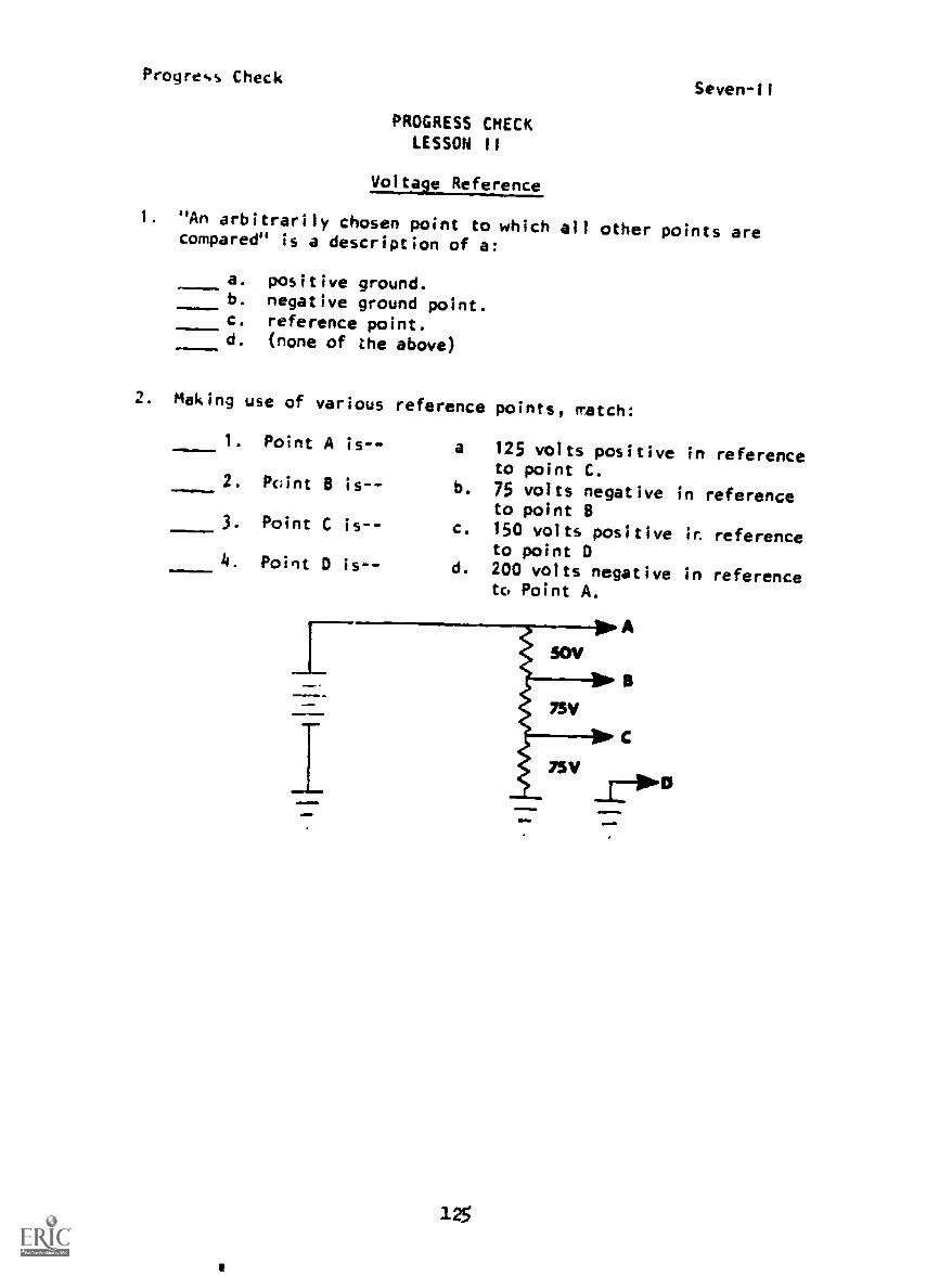
Voltage Reference
1. "An arbitrarily chosen point to which all other pointscompared" is a description of a:
4.,==
01=110.
a.
b.
c.
d.
positive ground.negative ground point.reference point.(none of the above)
2. Making use of various reference points, match:
1. Point A is-- a
2. Pvint B is-- b.
3. Point C is-- c.
4. Point D is-- d.
12
125 volts positive into point C.75 volts negative into point B150 volts positive ir
to point D200 volts negative intc, Point A.
7SV
A
B
are
reference
reference
reference
reference
Progress Check Seven-11
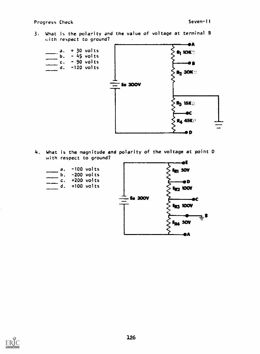
3. What is the polarity and the value of voltage at terminal Bwith respect to ground?
a.
b.
c.
d.
+ 30 volts- 45 volts90 volts
- 120 volts
4. What is the magnitude and polarity of the voltage at point Dwith respect to ground?
a. -100 voltsb. -200 voltsc. +200 voltsd. +100 volts
126

Progress CheckSeven -ti
5. What is the polarity of the voltage at Point A with respectto R?
AmMiMemIN.1
a. positive
b. negative
6. What is the potential and polarity at point B with respectLo A?
Aa. + 50 voltsb. +200 voltsc. - 50 voltsd. +300 volts
=1.
127

Progress Check Scven-II
7. What is the polarity an'' magnitude of the voltage at point Ewith respect to point B?
11011
a. -35 voltsb. +40 voltsc. +65 voltsd. -70 volts
128

Progress CheckSeven-III
PROGRESS CHECKLESSON III
Voltage Dividers
I. Which feature of a voltage divider enables it to supply voltagesof positive and/or negative polarity?
a. number of series resistors.b. size of resistors used.c. location of reference point.d. number of loads attached.
2. What is the polarity of point C with respect to Point B?
a. negative
b. positive4
c. no polarity can be assigned
_yr
0A
3. What is th.e magnitude and polarity of point A with respectto ground?
a. negative 40 voltsb. positive 60 voltsc. negative 60 voltsd. positive 20 volts
129

Progress Check Seven-ill
4. What is the polarity and voltage at terminal C with respect topoint A? A
a. -40 vb. +60 v
c. -60 vd. -200 v
5. Which of the following diagrams shows the correct direction ofcurrent flow, using the electron theory of current flow?
a.
C.
3.30
b.
d.

Progress CheckSeven-111
6. What effLct will closing S1 have on total circuit current?
a. Total circuit current will decrease.b. Total circuit current will increase.c. Total circuit current will double.d. Total circuit current will not change.
.a..10
7. Closing SI will cause the voltage across R2 to:
a. decrease.b. increase.c. increase to source voltage.d. not change.
1011MI
131
=m1M111

Progress Check Seven-Ill
8. What effect will closing S1 have on total resistance?
!!.1!,,
a. increaseb. not changec. decreased. increase to infinity
9. What effect will opening Si have on the voltage dropped across Ri?
a. increaseb. not changec. increase to source voltaged. decrease
132

Progress CheckSeven-III
10. Moving the arm of load 1 to point A will cause ERI to:
11. Solve.
a.
b.
c.
d.
double.
increase.decrease.
stay the same.
a. I
T=
b. R, =I -c. E
RI=
d. E =R2 ----f%f E =
9. Ri3 =
Mb!
133
LOAD I
LESSON I
PROGRESS CHECK ANSWERS
MODULE SEVEN
LESSON III
1. c 1. c
2. b 2. a
3. b 3. b
4. b 4. c
5. b 5. c
6. a 6. b
7. a 7. a
8. b 8. c
9. c 9. d
10. a 10. b
11. c
LESSON
1. c
2. 1-a
2-c
3-b
4-d
3. c
4. b
5. a
6. c
7. d
11. a. 22 ma
b. 4.5 kl
c. 55 v
d. 17.5 v
e. 7 ma
f. 27.5 v
g. 18.3
IF YOUR ANSWERS ARE ALL CORRECT, YOU MAY TAKE THE MODULE TEST. IF
NOT, STUDY ANY OF THE OTHER RESOURCES AVAILABLE FOR THIS LESSON BEFORE
TAKING THE PROGRESS CHECK AGAIN.
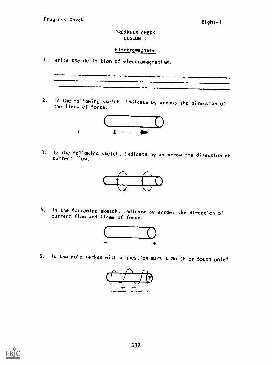
C C)
Progress Check
PROGRESS CHECKLESSON I
Electromagnets
1. Write the definition of electromagnetism.
Eight-1
2. In the following sketch, indicate by arrows the direction ofthe lines of force.
(
3. In the following sketch, indicate by an arrow the direction ofcurrent flow.
4. In the following sketch, indicate by arrows the direction ofcurrent flow and lines of force.
MI=
5. is the pole marked with a question mark r. North or South pole?
139

Progres Check Elght-1
6. State in your own words the two primary purposes for using arelay.
2.
DON'T
GET
.0 NEDON
PLAY ITCO L WITH
ELECTRICITY
1140

Progress CheckEight-II
PROGRESS CHECKLESSON If
inductors and Flux Density
1. Match the statement in A to the drawings in B.
A
1. has higher permeability
2. has higher reluctance
3. has less permeability
4. has less reluctance
B
a. LAM M/
b.
2. List the five factors that affect flux density in an inductor.
Directly Proportional (Any order.)a.
b.
c.d.
Inversely Proportional
e.
141

Progress Check Eight-Ill
PROGRESS CHECKLESSON III
Irducing a Voltage
1. Three factors are necessary to generate an EMF by magneticinduction. List the three factors. (Any order.)
a.
b.
C-
2. The magnetic field generated by a current-carrying conductororiginates:
a. along the skin area of the conductor.b. in the immediate area around the conductor.c. instantaneously throughout the conductor.d. in the center of the conductor.
3. When a circuit is first energized, the magnetic field:
a. expands.b. collapses.
4. With the field moving outward, the conductor movesin relation to it.
5. Relative motion exists in a current-carrying conductor due tothe and field.
6. The EMF induced in a conductor due to a changing magnetic fieldthe current that causes it.
7. The induced EMF opposes circuit EMF. This induced EMF is calledEMF..11liw.
8. The induced EMF is of value after current reachesa steady value.
1L2

Progress Check
9. When current is in a steady state and he circuit is opened,the starts to collapse.
10. When the magnetic field is collapsing, the CEMF is in such adirection that it attempts to current flow.
On the schematic, indicate (with polarity signs) the polarity ofCEMF at the instant SW1 is closed.
12. On the schematic, indicate (with signs) the polarity of CEMF atthe instant SW1 is opened.
Smiq
13. Indicate the polarity of induced EMF in Lircuit B when circuit Ais first energized.
.1111.41111110rwp
A
T
1143
Progress Check Eight-111
14. Which of the statements below is known as Lenz's Law?
to source voltage, the sum is zero.d. The polarity of the induced EMF is such that it tends
to set up a current flow that opposes the originalcurrent.
a. The sum of the voltage drops around a series circuit willequal source voltage.
b. The direction of the voltage drops is such as to add tosource voltage.
c. The polarity of the voltage drops is such that when added
15. CEMF' is present in a circuit only when circuit current is
16. A source that will supply a continuously changing value of Eand 1 is a/an source.

Progress CheckEight-IV
PROGRESS CHECKLESSON IV
Induction and Inductance
1. Inductance is the property of a circuit that opposes any changein circuit
2. A change in circuit current produces a/an thatopposes this change.
3. Lenz's Law is the basis for explaining the property of
4. The voltage produced by the property of inductance is called
5. The opposition felt by a changing current is due to circuit
6. The CEMF present in a circuit due to inductance thesource current.
7. Inductance is symbolized by the letter L and is measured in
allMIIMO.MIaIMP
a. farads.b. henrys.c. ohms.d. mhos.
8. Very small units of inductance are normally expressed ashenrys or henrys.
9. To find LT
of a three-branch parallel inductive circuit, theformula would be used.
10. In parallel, total inductance is always the smallestinductance.
1145
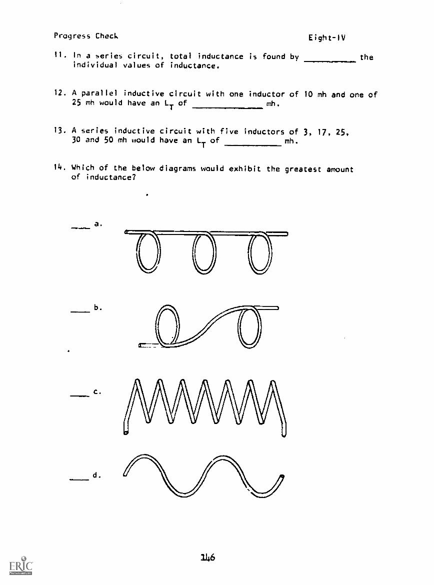
Progress Check Eight-1V
11. In a series circuit, total inductance is found by theindividual values of inductance.
12. A parallel inductive circuit with one inductor of 10 mh and one of25 mh would have an LT of mh.
13. A series inductive circuit with five inductors of 3, 17, 25,30 and 50 mh would have an L
Tof mh.
14. Which of the below diagrams would exhibit the greatest amountof inductance?
a.
b.
c.
d.
116

Progress CheckEight-1V
15. List three physical means available for increasing the magneticfield strength of an inductor.
a.
b.
C.
16. To determine the direction of the inductive magnetic field,you would use the for coils.
17. Inserting a core into a coil will create a greater concentrationof
18. inductance be affected by increasing currentthrough the coil.
19. List three physical means of increasing induction between twocoils.
a.
b.
G.
20. Two coils positioned at right angles will exhibitmutual inductance.
21. Coefficient of coupling will be greatest between which of thecoil pairs below?
117
I I
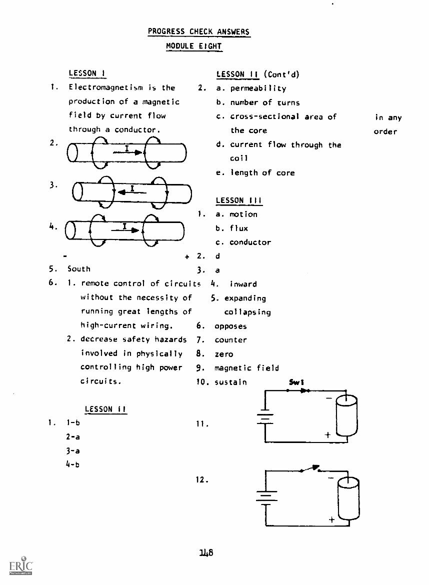
PROGRESS CHECK ANSWERS
MODULE EIGHT
LESSON I LESSON II (Cont'd)
1. Electromagnetism is the 2. a. permeability
production of a magnetic b. number of turns
field by current flow c. cross-sectional area of in any
through a conductor. the core order
2. ,
L-IIPd. current flow through the
coil
e. length of core
"C\3.
LESSON III
1. a. motion
b. flux
c. conductor
+ 2. d
South 3. a
1. remote control of circuits 4. inward
without the necessity of 5. expanding
running great lengths of collapsing
high-current wiring. 6. opposes
2. decrease safety hazards 7. counter
involved in physically 8. zero
controlling high power 9. magnetic field
circuits. 10. sustain Swi
LESSON II
1. 1-b
2-a
3-a
4-b
12.
1148

PROGRESS CHECK ANSWERS MODULE EIGHT
13.
LESSON III (Cont'd) LESSON IV (Contid)
13. 125 mh
14. c
15. a. increasing turns in coil
b. decreasing space between turns
c. inserting iron core
16. left-hand rule
17. lines of flux
14.
15.
16.
d
changing
alternating
18. will not
19. a. decrease space between coils
b. use high permeability core material
c. increase coil turns
LESSON IV 20. zero or no
1. current 21. a.
2. voltage or CEMF
3. inductance
4. CEMF
5. inductance
6. opposes
7. b
8. milli
micro (either order)19
LT1, 1
Ll
1
L2 tr
10. less than
11. adding
12. 7.1 mh
IF YOUR ANSWERS ARE ALL CORRECT, YOU MAY NOW TAKE THE MODULE TEST. IF
NOT, STUDY ANY OF THE OTHER RESOURCES AVAILABLE FOR THIS LESSON BEFORE
TAKING THE PROGRESS CHECK AGAIN.
149-

Progress Check Nine -1
PROGRESS CHECKLESSON I
Rise and Decay of Current and Voltage
I. In a DC LR circuit, when the circuit is first energizes, voltagedrop is across the inductor.
2. At the instant the circuit is energized, circuit current isand E
Ris
3. After five time constants, voltage drop across the resistoris and circuit current is
4. When current has stabilized (five time constants), voltagedrop across the inductor is
5. As circuit current is increasing, energy is being stored ina/an field about the coil.
6. Removing the source and shorting the LR branch will causethe magnetic field to and current will flow inthe direction.
7. Which of the graphs below correctly indicates CEMF,and 1 at 15 when the switch is opened?
a.
b.
cmomigimmommswAlmmakimemmilimpnmumm.._mmusawnam.11 mmosrumws
molimimmillOMMIPAggiMmompplimm
niummumimmsmammanknomOMMOWAOW9MmimprumilmmaimsImploommmommmvaimmommsrimmmummillmmmommil ma
TO T1 r2 13 14 TS T9 T10
Curve a = 1 and ER
Curve b = CEMF and EL

Progress Check Nine-I
8. on the growth and decay graph, the horizontal base represents
9. The purpose of the graph is to pictorially represent the valuesof voltage and current in reference to
10. The vertical base of the graph represents circuit values of Eand 1 in either a or direction.
11. Which graph represents current in a DC circuit containing onlyresistance when the switch is closed at Ti?
a.
r 6 - -+ -h-7 ITo T1 T2 T3 T4 T5
Tb.
.
L . J .
t
TO T1 T2 T3 T4 T5
12. Current is slower to reach its maxir,um value in a circuit con-taining inductance due to the generated by the inductor.
13. The of the LR circuit is greatest at Ti deeto the rate of change of current being greatest at this instant.
14. The polarity of the CEMF always the source EMFduring current rise.
1514

Progress Check Nine-1
15, When a circuit is first de-energized, the value ofor is maximum.
16. What values are represented by the graph below when a DC LRcircuit is energized?
IIMMIME.I.IIIMM
a. EL
curve A; ER
curve B
b. ER
curve B; I curve B
c. ER curve A; E
Lcurve B
d. C.E.M.F. curve A; I curve A
155

Progress Check Nine-I
17. On the graph below, the greatest rate of change is at times:
1----+
1--- --i---t------ti
1---
T4 T3 14 T5 T6 T7 T8 T9 T I
a. T1-T2 and T6-T7.-b. T2-T3 and T5-16.
c. T1 -T2 and T5-16.d. T2-13 and T6-T7.
TIME
156

Progress CheckNine-II
PROGRESS CHECKLESSON II
LR Time Constant
1. A time constant is the length of time required for current toincrease or decrease to of its maximum or minimumvalue.
2. The greatest increase or decrease in current takes place duringthe:
a. first TC.b. second IC.c. third IC.d. fourth TC.
3. A circuit time constant is determined by the formula:
a. TC =
1 b. TC =L
c. TC = R Ld. TC = RL
4. For practical purposes five time constants are required toreach I maximum. Each time constant of the five is:
a. of equal time.b. inversely proportional to CEMF.c. varied as current varies.d. proportional to applied voltage.
5. The time constant of an LR circuit containing an inductorof 50 millihenrys and a resistor of 5 Kohms is:
a. 0.01 secondsb. 10 secondsc. 10 .secondsd. 10 mseconds
157

Progress Check Nine-11
6. From the previous question, we find that it will take
for circuit current to reach maximum.
a. 50.. seconds
b. 63. seconds
c. 78, secondsd. 86.. seconds
7. Which of the following combination, will have the greatesttime constant?
a. R= 100. L 10..h
b. L = 100 mh R = 100..
c. R = SO, L = SOO mhd. L= 10 h R=
8. With a maximum value of 7 amps possible, current will beamps after two time constants of current rise.
On the graph below, indicate correct values of percentage ateach point indicated.
C
8
A
TO 11 T2
158
T3 T4
E
T3
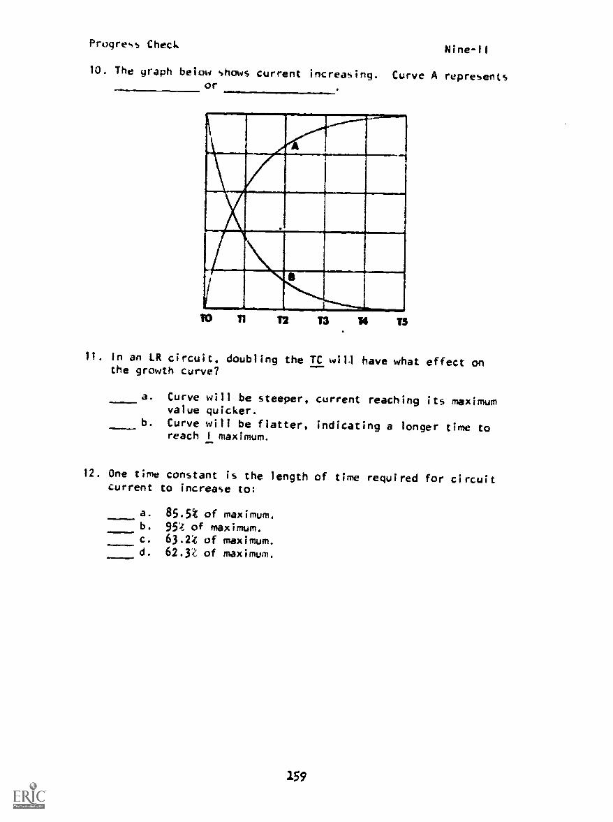
Progress CheckNine-11
10. The graph below shows current increasing. Curve A representsor
T2 T3 T5
11. In an 1.Ft circuit, doubling the TC will have what effect onthe growth curve?
a. Curve will be steeper, current reaching its maximumvalue quicker.
b. Curve will be flatter, indicating a longer time toreach 1 maximum.
12. One time constant is the length of time required for circuitcurrent to increase to:
alwafea.Mob.
a. 85.5% of maximum.b. 954 of maximum.c. 63.24 of maximum.d. 62.3'4 of maximum.
159
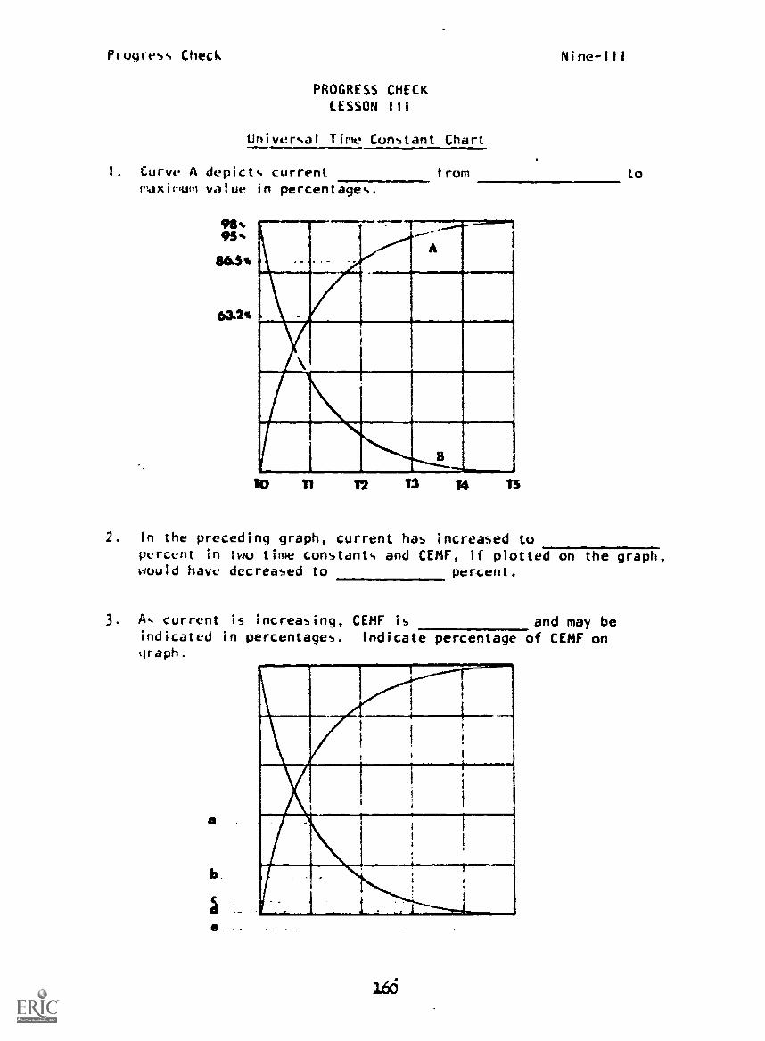
Progress Check Nine-Ill
PROGRESS CHECKLESSON III
Universal Time Constant Chart
1. Curve A depicts currentpldximum value in percentages.
pMMe..0011.114,!..a...Mil-as.am.
63.24
12
from to
T3 /4 T5
2. In the preceding graph, current has increased topercent in two time constants and CEMF, if plotted on the graph,would have decreased to percent.
3. As current is increasing, CEMF is and may beindicated in percentages. Indicate percentage of CEMF ongraph.
a
I
.
V
1
I
i
I,
16(5
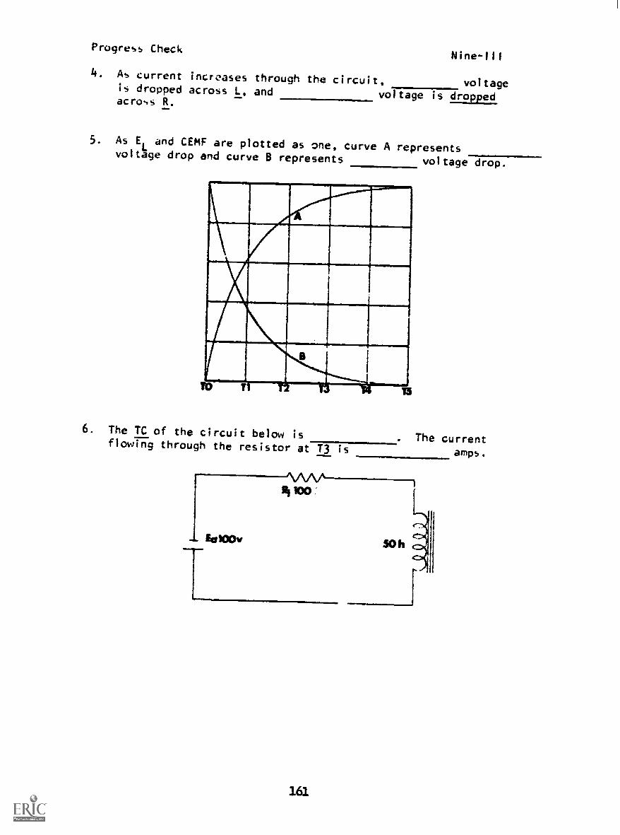
Progress CheckNine-111
4. As current increases through the circuit, voltageis dropped across L. and voltage is droppedacross R.
5. As EL and CEMF are plotted as one, curve A represents
voltage drop and curve B represents voltage drop.
6. The TC of the circuit below isflowing through the resistor at T3 is
. The currentamps.
161

Progress Check Nine-III
7. Using circuit values in question 6, indicate on the graph thevalues of I
Rat IC points indicated. Draw in the other curve
and indicate the value of CEMF/ELat TC points.
1.00
A
S 40
mlh
TO T1 12 T3 S4 TS
8. Again using the circuit in question 6, plot on the graph thevalues of E
Rat all five time constant points.
TO T2
162
T3 T4 TS

Progress Check Nine -Ill
9. On the graph draw the ER and EL
curves and indicate the pointat which ER = EL.
a
10 T1 T2 T3 T4 TS
10. In a circuit containing an L of 500 mh, a resistance of1,000.. (1 k..) , and a source of 250 v,
a. the value of the maximum voltage drop across L isvolts at Time
b. the maximum resistive voltage drop is voltsat TC
c. the TC isd. the maximum current possible is
11. Doubling the value of L in question 10 will cause IC to
12. Decreasing the value of R in question 10 by one-half willcause L to
13. With an R of 1 k , and L of 5,000 mh, TC will be
14. If a source of 500 volts is added to the circuit in question 13,a current of amps will be flowing at 13.
15. Decreasing the source voltage of question 14 by one-half and Rby one-half will cause IT to
163

Progress Check Nine-IV
PROGRESS CHECKLESSON IV
Inductive Reactance
I. The property of a coil is such that it anychange in
2. Frequency is a factor in determining the opposition an inductoroffers to circuit current; hence, an inductor is acomponent.
3. By combining inductance and its property of reactance, we getwhich is symbolized by
4. Inductive reactance is an opposition to current and is measuredin
5. Unlike resistance, however, XL
is affected by changes in
6. As.
XL
is determined in part by frequency of the source, a cir-cuit containing a source of 250 volts DC would exhibit
XL
.
(maximum, minimum, zero)
7. The formula for determining the reactance of a coil isXL
=
8. From the formula for inductive reactance, it is easy to seethat and are variables andis a fixed value.
164
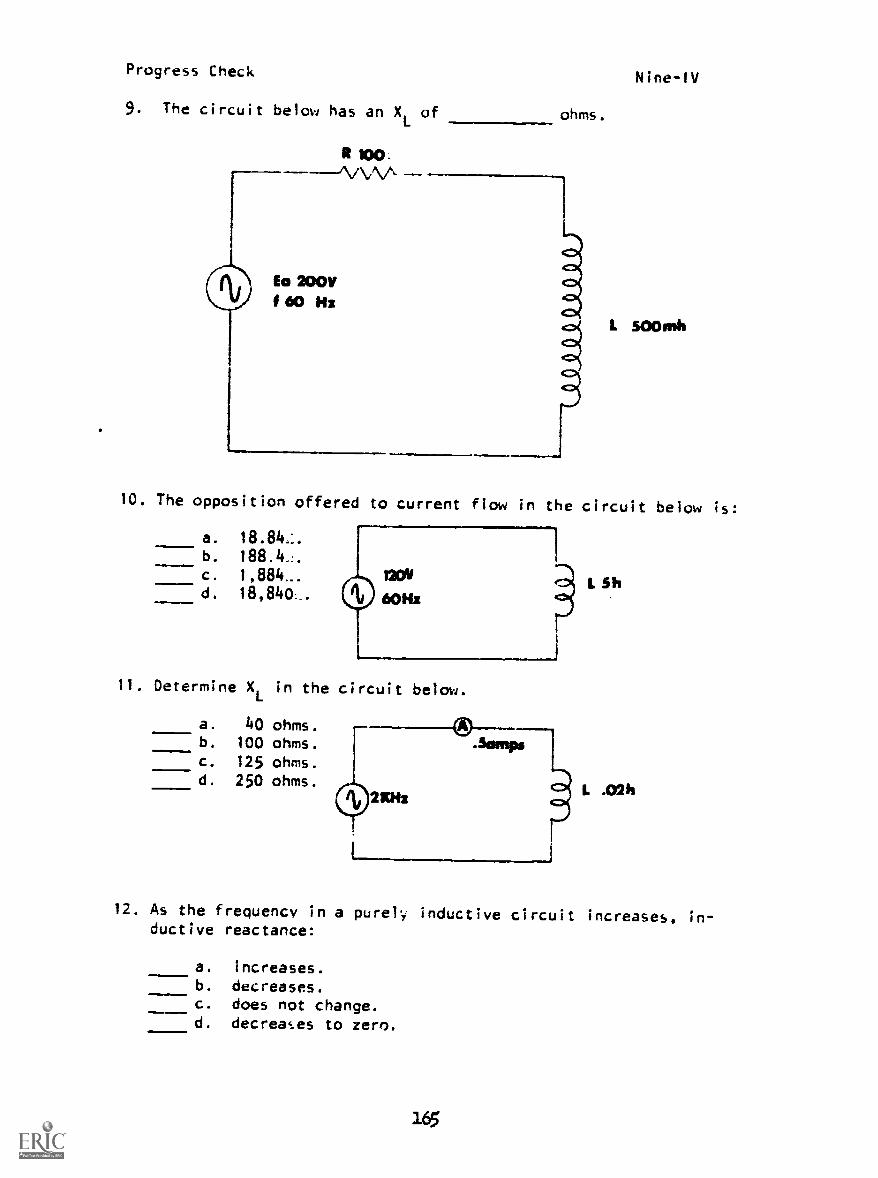
Progress Check Nine-1V
9. The circuit below has an XL
of
Eo 2001/
f 60 Nz
it too:
ohms.
10. The opposition offered to current flow in the circuit below is:
a. 18.84...b. 188.4-!.
c. 120V
d. 18,840.. 6O Hz
11. Determine X1 in the circuit below.
a. 40 ohms.b. 100 ohms.c. 125 ohms.d. 250 ohms.
L Sh
L .02k
12. As the frequency in a purely inductive circuit increases, in-ductive reactance:
11111..111b
a. increases.b. decreases.c. does not change.d. decreases to zero.
16

Progress Check Nine-1V
13. Which of the following determines the inductance ofa coil?
a. frequencyb. voltagec. currentd. physical construction
14. The henry is the unit of:
a.11.111w..
a. inductanceb. resistancec. capacitanced. impedance
15. A coil is said to possess an inductance of 1 henry if an EMFof 1 volt is induced in the coil when a current through thecoil is changing at the rate of per second.
a. 1 ampereb. 2 amperesc. 3 amperesd. 4 amperes
16. if you increase the input frequency of a circuit from 60 Hzto 120 Hz, the inductance will:
a. double.b. halve.
c. increase.d. not change.
166

Progress Check Nine-V
PROGRESS CHECKLESSON V
Relationships in Inductive Circuits
1. The value of reactive power (Px) is determined by using theformula
2. XL
is an apposition to current as is R. The circuit currentbelow is amps.
=
3. Since an inductor reacts to frequency changes, what effect wouldthe following values experience if frequency were doubled? Answerincrease, decrease, or remain the same to each part.
a. XL
b. I
T
c. ER
d. EL
e. R
4. In an LR circuit, what would happen to Pt if frequency wereincreased?
5. What effect would increasing the frequency have on an inductor'smagnetic field?
6. True power Is dissipated only in a circuit whi.h contains
167
Prugress Check Nine-V
7. In an inductive circuit containing no resistance, power inthe circuit is classed as power.
8. All power in a purely reactive circuit is not in realityconsumed; it is stored in a field.
9. Since it is returned to the circuit on the next half cycle, itis called power.
10. Power stored in a reactive circuit is measured in
168

Progress CheckNineVI
PROGRESS CHECKLESSON VI
Phase Relationships in Inductive Circuits
I. In an inductive AC circuit the current lags the applied voltageby:
a. 360°.b. 270°.C. 180°.d. 90°.
2. The CEMF of a coil will be greatest when the current sine waveis at:
=111! a. maximum negative value.b. passing through 0 value.c. .707 of maximum value.d. maximum positive value.
3. In an AC inductive circuit, the voltage is such that it:
a. lags current by 90°.b. is in phase with current.c. is out of phase with the current by 180o .
d. leads current by 90°...wrmallF
4. In the circuit below, what phase relationship exists betweenthe voltage applied to the conductor and the self-inducedvoltage in the conductor.
a. E.ind
leads Ea
by 90°
b. Ea
leads Eind
by 90o
c. Ea
and Eind are in phase.
d. Eind
and Ea
are 180° out of phase.
169

Progress Check Nine-VI
5. Which vector diagram correctly represents the phase relationshipbetween voltage and current in a purely inductive circuit.(Current is the reference value.)
b.
d.
6. At what point on this current sine wave is the current goingthrough its greatest rate of change.
7. Which vector diagram correctly represents the phase relationshipbetween applied voltage and CEMF.
a. CEMF b.
C. d.
lEa
CEMF
170

PROGRESS CHECK ANSWERSram NINE
LESSON I LESSON 11.(Cont'd)1. maximum 9. C. 95t2. minimum and minimum O. 982
3. maximum and maximum E. 100'
4. zero 10. I, ER
5. magnetic 11. b
6. collapse, same 12. c
7. a
8. time
9. time
10. positive, negative
II. a
12. CEMF
13. CEMF
14. opposes
15. CEMF, EL
16. e
17. c
LESSON II
1. 63.2%
2. a
3. a
4. a
5. c
6. a
7. d
8. 6.05 amps
9. A. 63.2%
B. 86.5%
AMPS
LESSON III
1. growth or rise, minimum
2. 86.5%, 13.5%
3. decreasing
a. 36.8',f,
b. 13.5%
c. 5%
d. 2%
e.
4. less, more
5. resistive, inductive
6. 0.5 seconds, 0.95 a or 950 ma
7.
11111Mill.fin. IIIYAIIMIE111M111111111111
T
171
LOA
remaining
CEMF/EL
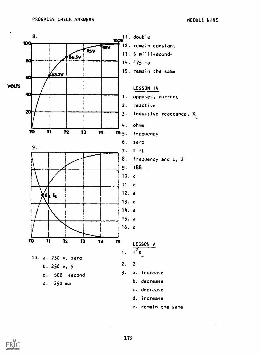
PROGRESS CHECK ANSWERS MODULE NINE
8
9SV
63.2V
T1 T2 T3 T4
9
11. double
12. remain constant
13. 5 milliseconds
14. 475 ma
15. remain the same
LESSON IV
1. opposes, current
2. reactive
3. inductive reactance, XL
4. ohms
T5 5. frequency
6. zero
1111=11111WANE1,11111.=WM
T1 T*4 13
10. a. 250 v, zero
b. 250 v, 5
c. 500 second
d. 250 ma
14 T5
7. 2 fL
8. frequency and L, 2-
9. 188 .
10.
11. d
12. a
13. d
14. a
15. a
16. d
LESSON V
1. I
2XL
2. 2
3. a. increase
b. decrease
c. decrease
d. increase
e. remain the same
3.72

PROGRESS CHECK ANSWERSMODULE NINE
LESSON V (Cont'd)
4. Ptwould decrease
5. changes will be faster
6. resistance
7. reactive
8. magnetic
9. reactive power
10. volt amps reactive (var)
LESSON VI
1. d
2. b
3. d
4. d
5. d
6. c
7. b
IF YOUR ANSWERS ARE ALL CORRECT, YOU MAY TAKE THE MODULE TEST. IF NOT,STUDY ANY OF THE OTHER RESOURCES AVAILABLE FOR THIS LESSON BEFORE TAKINGTHE PROGRESS CHECK AGAIN.
173-

Progress CheckTen-I
PROGRESS CHECKLESSON 1
Transformer Construction
1. Due to the methods of construction and materials used, main-tenance of ordinary transformers is required:
a. weekly.b. monthly.c. infrequently.d. often.
2. An air-core transformer, is best at:
a. high frequencies.b. low frequencies.c. high current.d. high voltage.
3. The schematic symbol below is for a/an trans-former.
a.
b.
c.
d.
step-down, iron-corestep-up, paper-corestep-down, air-corestep-up, iron-core
1:2
4. The schematic symbol below is for a/anf firmer.
a. step-down, iron-core, tapped secondaryb. step-up, air-core, tapped primaryc. step-down, air-core, tapped secondaryd. step-up, iron-core, tapped secondary
177
trans-
t3

Progress Check Ten-I
5. The schematic symbol below is for a/an trans-former.
=411111111=,
a. step-down, iron-coreb. step-up, air-corec. step-down, air-cored. step-up, iron-core
3:1
6. A transformer is a device that transfers electrical energyfrom one circuit to another electrically-isolated circuit by:
a. magnetizing current.b. electromagnetic induction.c. exciting current.d. eddy current.
7. An iron core is used in a power transformer in order to:
a. concentrate the field about the 14indings.b. release the high-frequency currents.c. disperse the field about the windings.d. increase the eddy currents.
S. The part of a transformer connected to the source is called the:.1111
a. primary winding.b. secondary winding.c. iron core.d. laminations.
9. The material used to separate the core laminations of a powertransformer is usually:
a. paper.b. carbon.c. lead.
d. varnish.!178

Progress Check Ten-I
10. A transformer designed for low-frequency operation requiresa core of:
a. low permeability.b. low reluctance.c. high retentivity.d. high copper loss.
II. iron -core transformers are normally used at:
a. low frequencies.b. low voltages.c. high currents.d. high frequencies.
12. The coefficient of coupling for the two coils would be:
a. maximum.b. minimum.c. average.d. effective.
179

Progress Check Ten-11
PROGRESS CHECKLESSON 11
Transformer Theory and Operation
1. On the scheptatic. the dots indicate the:
a. areas where the insulation has broken down.b. top lead of the primary and secondary have the same
polarity.c. primary and secondary have the same number of windings.d polarity of the secondary is opposite to the primary.
2. A step-down transformer receives energy at one voltage anddelivers it at a/an:
a. equal voltage.b. lower frequency.c. lower voltage.d. higher voltage.
3. The small current that flows in the primary winding of a
transformer with no load connected to the secondary is calledthe current.
a. secondary.b. exciting.c. eddy.d. leakage.
4. The extent of coupling between two inductors is expressed by:
a. varying current.b. counter EMF.c. self-inductance.d. coefficient of coupling.
180
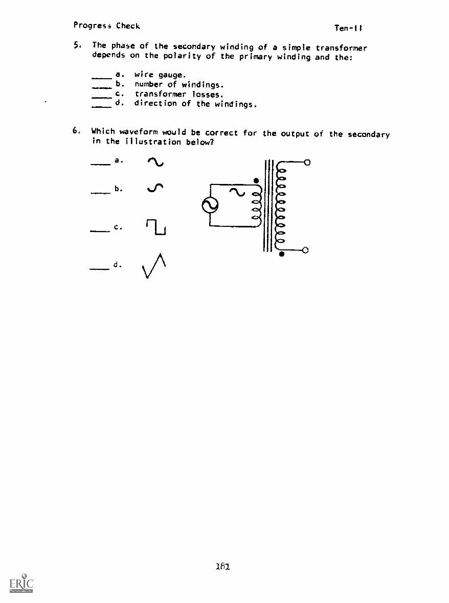
Progress Check Ten-11
5. The phase of the secondary winding of a simple transformerdepends on the polarity of the primary winding and the:
a. wire gauge.b. number of windings.c. transformer losses.d. direction of the windings.
6. Which waveform would be correct for the output of the secondaryin the illustration below?
c.
d.
ti
181

Progress Check
PROGRESS CHECKLESSON III
Turns and Volta9e Ratios
1 It the primary of a power transformer has 2,000 turns with120 volts AC applied, how many turns are needed in the secondaryto have an output of 6 volts AC?
a. 60 turnsb. 100 turnsc. 166 turnsd. 600 turns
2. A step-up transformer has low:
a. voltage input, high-voltage output.b. current input, high-current output.c. power input, high-power output.d. frequency input, high-frequency output.
3. a 5:1 ratio step-down transformer has 250v on the pr inkiry,.chat i the secondary voltage?
4. 25vb. 50vc. 250vd. 1250v
4. Compute the output voltage (ERL) in the illustration below.
a. 40vb. 30v
c. 400vd. 600v
110

Progress Check Ten-Ill
5. A step-down transformer receives energy at one voltage anddelivers it at a/an:
a. equal voltage.b. lower frequency.c. lower voltage.d. higher voltage.
6. A transformer which has a lower secondary voltage than primaryvoltage is a/an:
a. step-up transformer.b. air-core transformer.c. step-down transformer.d. iron-core transformer.
7 If the primary of a power transformer has 400 turns with120v AC applied, what is the voltage output from a 50 turnsecordary?
a. 12 Vb. 15 vc. 20 vd. 25 v
183

Progress Check Ten-IV
PROGRESS CHECKLESSON IV
Power and Current
1. It a 3:1 ratio step-down transformer has 3 amps of current inthe primary, what is the current in the secondary?
a. la
b. 3a
c. 9ad. 6a
2. How much current is flowing through the resistive load in thecircuit below? ra. 3 amps_
b. 4 ampsc. 5 amp.,
d. 6 arlps Np1000 TURNS
1p 2A
P45
400 TiliNSS
3. In the illustration below the applied voltage is:
a. 400 vb. 20 vc. 40 vd. 200 v
is 2A
Es 200V
4. In a step-down transformer the current through the secondarywill be:
a. less than the current in the primary.b. greater than the current in the primary.c. the same as the primary.d. directly proportional to frequency.
1814

Progress Check Ten-IV
5. In the circuit below, if the switch is closed, the currentflow in the primary will:
a. increase.b. decrease.c. not change 4
(S)d. stop.
6. In a step-up transformer the primary current is:
a. more than the secondary current.b. less than the secondary current.c. equal to the secondary current.d. equal to the coefficient of coupling.
7. Compute the primary current flow for the transformer shown below.
a. 2 amps.b. 3 amps.c. 6 amps.d. 9 amps.
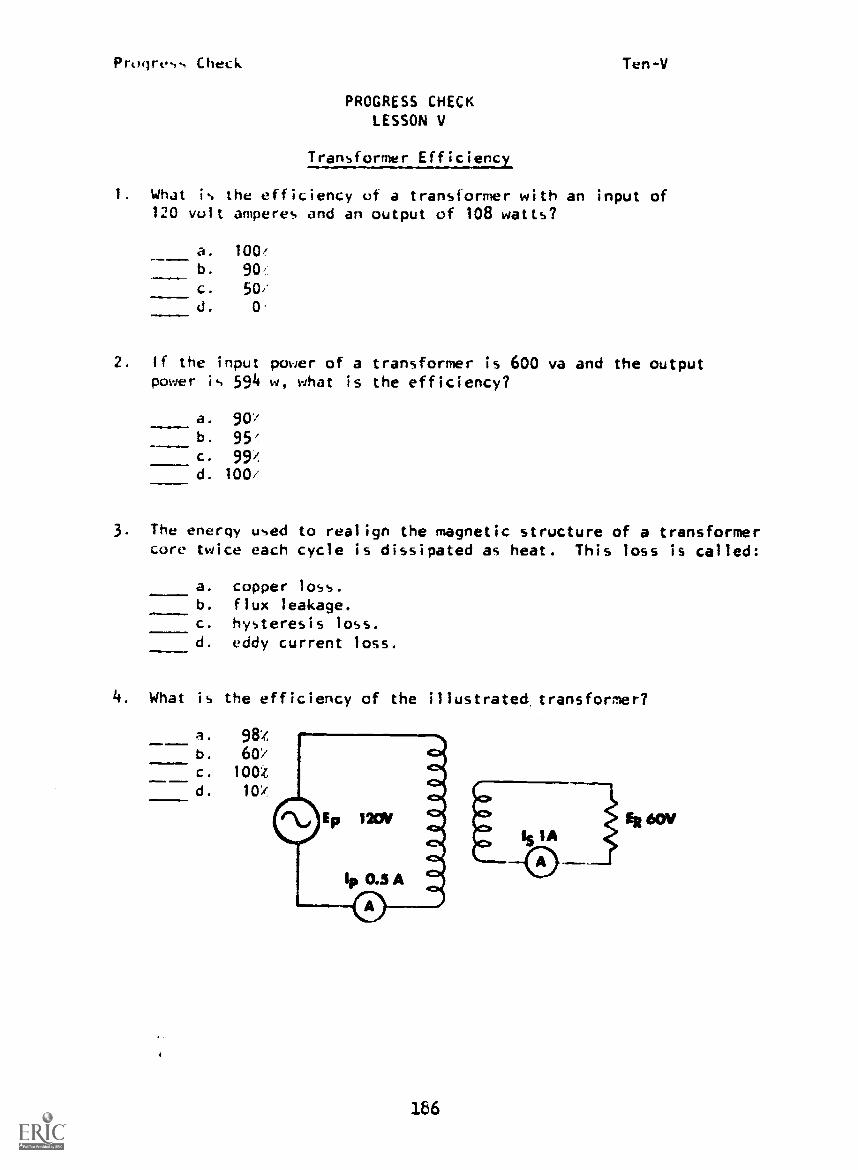
Progress Check Ten-V
PROGRESS CHECKLESSON V
Transformer Efficiency
1. What is the efficiency of a transformer with an input of120 volt amperes and an output of 108 watts?
... a. 100/
b. 90,
c. 50/d. 0
2. If the input power of a transformer is 600 va and the outputpower is 594 w, what is the efficiency?
a. 9Oib. 95/
c. 99/d. 100,
3. The energy used to realign the magnetic structure of a transformercore twice each cycle is dissipated as heat. This loss is called:
a. copper loss.b. flux leakage.c. hysteresis loss.d. eddy current loss.
4. What is the efficiency of the illustrated transformer?
a. 98Zb. 60.,
c. 1001
d. 10:1
186

Progress CheckTen-V
5. Which type of transformer loss is reduced by using silicon steelas the core material?
a. copper lossb. flux leakagec. eddy currentsd. hysteresis loss
6. The undesirable currents in a transformer core arecurrents.
=1
a. ratiob. eddyc. primaryd. secondary
7. Transformer cores are laminated in order to:
a. increase displacement currents.b. reduce mutual inductance.c. provide an easy path for current.d. reduce eddy currents.
8. The current handling capacity of a transformer is determined bythe:
a. applied voltage.b. thickness of insulation.c. shape of the core.d. physical size of the wire used.
9. Copper losses may be minimized by using:
a. larger diameter wire.b. high-resistance wire.c. laminated cores.d. coaxial cable.
10. The power dissipated by winding resistance in a transformeris called I R loss, or loss.
a. eddy currentb. copperc. hysteresisd. core
,MIMMIM11M
187

Prugress Check Ten-VI
PROGRESS CHECKLESSON VI
Semiconductor Rectifiers
1. A semiconductor rectifier:
a. rectifies AC to pulsating DC.b. rectifies DC to AC.c. pulsates.
2. Select the schematic symbol for a rectifier.
a.
d.
---61f111117-
3. Select the drawing which will allow current to flow.

PROGRESS CHECK ANSWERS
MODULE TEN
LESSON 1 LESSON 1111. c if . c2. a 5. c3. d 6. c4. d 7. b5. a
6. bLESSON IV
7. a 1. c8.. a 2. e9. d 3. a10. b 4. b11. a 5. a12. b 6. a
7. cLESSON I I
1. dLESSON V
2. c 1. b3. b 2. c4. d 3. c5. d 4. c6. b 5. d
6. b
LESSON 111 7. d1. b 8. d2. a 9. a3. b 10. b
(Cant id)

PROGRESS CHECK ANSWERS MODULE TEN
LESSON VI
I. a
2.
3. b
,t
ACCIpENTS-don't just
eliaein?
KU COPY AVAILABLE
IF YOUR ANSWERS ARE ALL CORRECT, YOU MAY TAKE THE MODULE TEST. IF NOT,
STUDY ANY OF THE OTHER RESOURCES AVAILABLE FOR THIS LESSON BEFORE TAKING
THE PROGRESS CHECK AGAIN.
Progress Check Eleven-1
PROGRESS CHECKLESSON 1
The Capacitor
1. Two metal plates separated by a non-conductor is an exampleof a/an:
a. resistor.b. inductor.c. capacitor.d. generator.
2. The material between the plates of a capacitor is called the
I ..1111
a. farad.b. dielectric.c. reactor.d. inductor.
3. Charging of a capacitor occurs when electrons
M Fie
Imm N. G.
a. forced onto both plates.b. drawn from both plates.c. forced onto one plate and drawn from the other plate.d. drawn from the dielectric.
4. Energy is stored in a capacitor in the electrostatic fieldthrough the:
a. plates.b. dielectric.c. conductors.d. leads.
5. The energy used to create an electrostatic field throughthe dielectric in a capacitor is recovered when:
a. the electrons are permitted to return to their normalpositions on the plates.
b. the capacitor charges.c. current flows between the plates.d. a voltage source is connected across the plates.
195

Progre,, Lhet k Eleven-1
6. When d capacitor is charged, the bound electron' in thedielectric:
a, fron - to + charged plates.U. 1:!o tro..1 + to - charged plates.c. are hot affected by the charged plates.d. have their orbits distorted.
- -
7. A capacitor i.. able to store energy in an electrostatic field:
a. Lit t..-;een the plates.
b. on the plates.c. in the conductors.d. in the leads.
196

Progress Check Eleven-II
PROGRESS CHECKLESSON II
Theory of Capacitance
I. The property of a circuit which opposes a change in voltageis called:
a. resistance.b. inductance.c. capacitance.d. current.
2. In a given capacitor, changing the dielectric to one which has. greater dielectric constant will have what effect on itscapacitance?
NM1?...1
a. decreaseb. increasec. not changed. decrease by one-half
3. The capacitance of a capacitor is the plate area.
a. directly proportional tob. inversely proportional toc. equal to the square ofd. equal to the square root of
4. Which is the correct relationship between plate spacing andcapacitance?
a. Capacitance is directly proportional to the square of thedistance between plates.
b. Capacitance is inversely proportional to the square of thedistance between plates.
c. Capacitance is directly proportional to plate spacing.d. Capacitance is inversely proportional to plate spacing.
5. Since a capacitor reacts to a voltage change by producing aCEMF, a capacitor is said to be
a.
b.
c.
d.
inductive.resistive.
electromagnetic.reactive.
197

Progress Check
6. The capacitance of a capacitor isbetween the plate.,.
a. directly proportional tob. inversely proportional toc. equal to the square ofd. equal to the square root of
198
Eleven-II
the distance

Progress Check Eleven-III
PROGRESS CHECKLESSON III
Total Capacitance
1. Capacitance is the property of a circuit that opposes a changein:
a. current.b. voltage.c. resistance.d. capacitive reactance.
2. The plates of a capacitor are separated by a:
a. wire.b. coil.c. semiconductor.d. dielectric.
3. The plates of a capacitor, in relation to the conductors, have:
a. a small cross-sectional area.b. a large cross-sectional area.c. high resistance.d. low reactance.
4. The total capacitance in the below circuit is:
a. 12 Lf.b. 3
c. 1.2 J.d. 0.3 J.
199

Protires,-, Check Eleven-111
5. Determine total capacitance in the below circuit.
a. 2.75 .f.b. 1.62 ..f.
c. 6.5 ..f.
d. 0.154 f.
.25 ufd
6. Determine the total capacitance in the below circuit.
a. 1.2
b. 6.0 .fc. 1.0 f
d. 0.5 ,f
1.2 ufd
7. The total capacitance of the below circuit is:
a. 10 . f.
b. 20 . f.
c. 5 . f .d. 0.5 .f. ufd 110 ufd
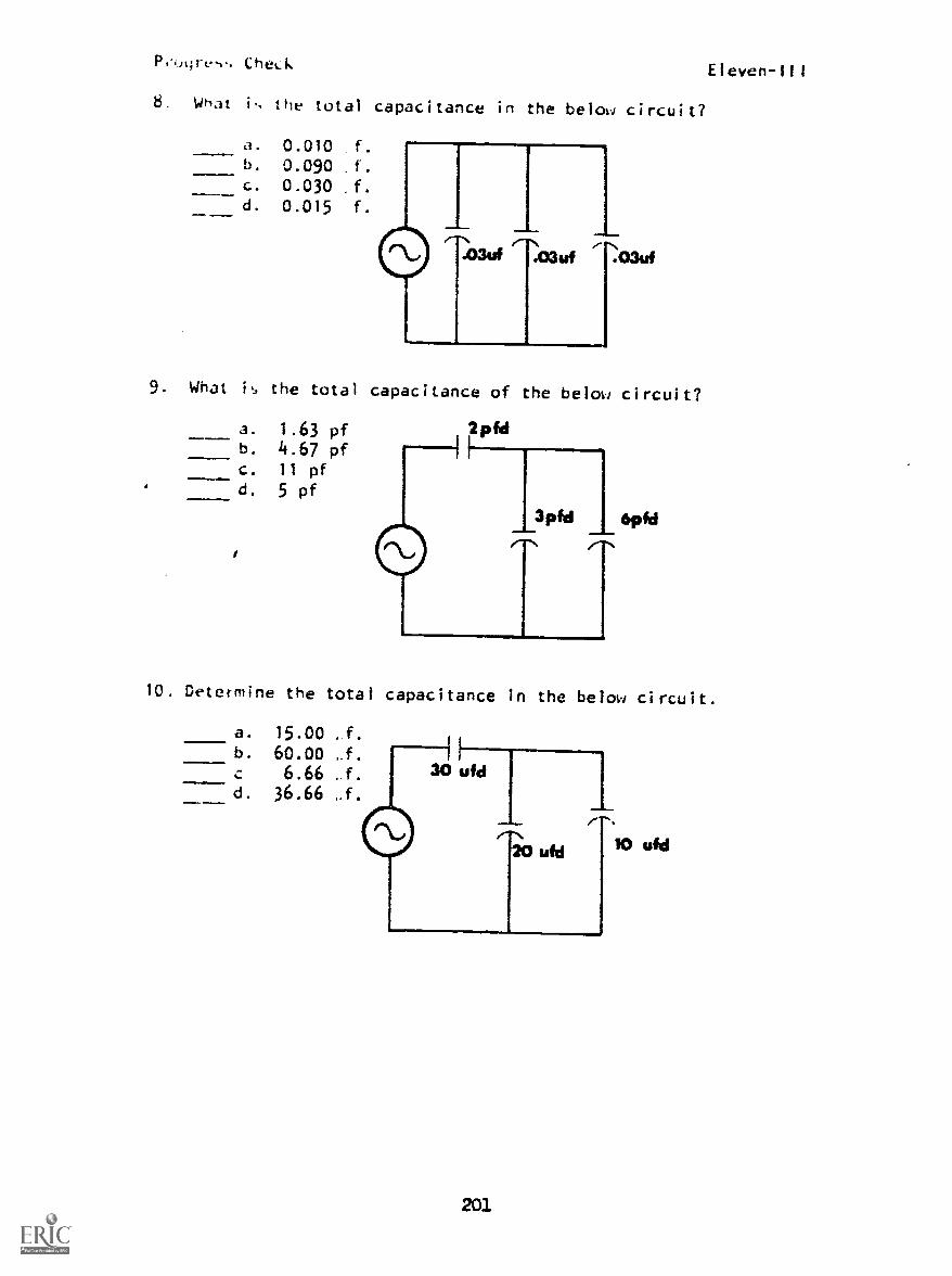
Pi.ogre,.. Check
8. What i., the total capacitance in the below circuit?
a. 0.010 f.
b. 0.090 f.
c. 0.030 f.
d. 0.015 f.
.O3uf .03W
9 What is the total capacitance of the below circuit?
a. 1.63 pfb. 4.67 pfc. 11 pfd. 5 pf
Eleven-111
10. Determine the total capacitance in the below circuit.
a. 15.00 , f.
b. 60.00 J.6.66 .f.
d. 36.66 J.
201

Progress Check Eleven-111
11. What is the total capacitance of the below circuit?
a. 5.45 pfb. 9.23 pfc. 90 pfd. 60 pf
12. The total capacitance of the below circuit is:
a. 40 pf.b. 20 pf.c. 10 pf.d. 5 pf.
20pfd
2Opfd
13. Determine the total capacitance of the below circuit.
a. 11 . f.
b. 1
c. 0.66 -f.d. 0.33 1.f. 1-
2
14. What is the total capacitance of the below capacitors?
Vufda. 2.94 ;.f.
b. 40 ,fc. 0.34 :If
d. 294 -f
202
25 ufd
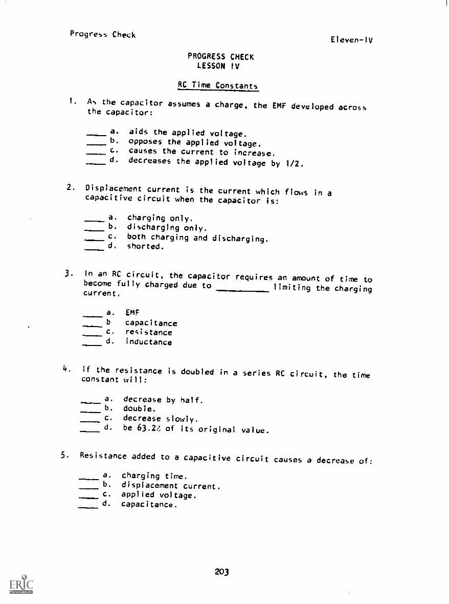
Progress CheckEleven-IV
PROGRESS CHECKLESSON IV
RC Time Constants
1. As the capacitor assumes a charge, the EMF developed acrossthe capacitor:
a. aids the applied voltage.b. opposes the applied voltage.c. causes the current to increase.d. decreases the applied voltage by 1/2.
2. Displacement current is the current which flows in acapacitive circuit when the capacitor is:
a. charging only.b. discharging only.c. both charging and discharging.d. shorted...111.1111=le
3. In an RC circuit, the capacitor requires an amount of time tobecome fully charged due to limiting the chargingcurrent.
=m...a. EMFb capacitancec. resistanced. inductance
4. If the resistance is doubled in a series RC circuit, the timeconstant will:
IDe
a. decrease by half.b. double.c. decrease slowly.d. be 63.24, of its original value.
5. Resistance added to a capacitive circuit causes a decrease of:
a. charging time.b. displacement current.c. applied voltage.d. capacitance.
203

Check Eleven -1V
L,. lhe ttiq..t adding re,i,.tince in a capacitive circuit i., to:
d . illcrea..c the charging_
b. decrea.,e the charging time.L. incras.e the current drawn.J. Jcrea.,e the total voltage drop.
/ W"dt cm..tant of the telex, circuit?
, . 0.3 fl,,ec.
b. 3U0 ;.!..ec.
L. 0.3J , 0.75
20
7 15 ufd
6. What the tirk. con..tant of the below circuit?
d. 1000 mecb. 100 ve,ec
C. 10 1,1.,ec
d. 1 n.,ec
10K
,100urd
5. Determine the value of vol tags across the capacitor at the end01 two time constants of discharge. The capacitor had 100 voitsaLross its plate,. when discharge started.
a. 86.5 v
b. 5.0 vc. 55.0 v
d. 13.5 v
2
10K
Sufd

Progress CheckEleven-IV
10. During charge time, the voltage across the capacitor afterfour time constants will be:
a. 237.5 v.b. 245 v.c. 12.5 v.d. 5 v.
apt
11. After two time constants, the voltage on the resistor in thebelow circuit will be:
a. 294.0 v.b. 259.5 v.c. 40.5 v.d. 15.0 v.
75.
of
12. During discharge, after 3 time constants, what is the value ofcurrent in the below circuit? The capacitor was fully chargedbefore discharge started.
=1.M.1 a. 0.1 amp.b. 1.0 amp.c. 1.9 amp.d. 0.2 amp.
205
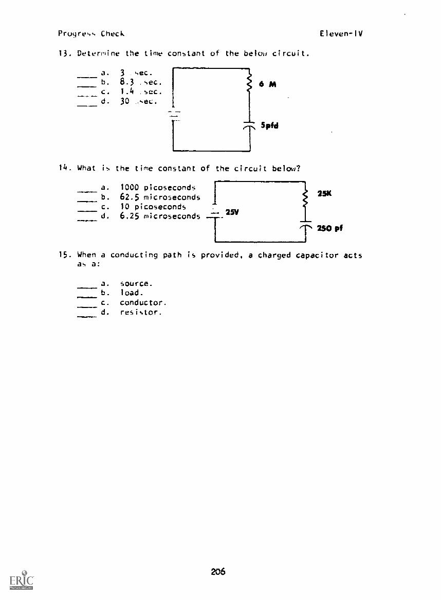
Progress Check Eleven-IV
13. Determine the time constant of the below circuit.
a. 3 sec.
b. 8.3 sec.
c. 1.4 sec.
d. 30 sec.
14. What is the time constant of the circuit below?
a. 1000 picosecondsb. 62.5 microsecondsc. 10 picosecondsd. 6.25 microseconds -- 25V
25K
250 pf
15. When a conducting path is provided, a charged capacitor actsas a:
a. source.b. load.
c. conductor.d. resistor.
206

Progress CheckEleven-V
PROGRESS CHECKLESSON V
Capacitive Reactance
1. The capacitance of a capacitor can be determined by:
a. dividing the voltage by the stored charge.b. multiplying the voltage by the stored charge.c. dividing the stored charge by the voltage.d. dividing the rate of change of current by the voltage.
2. A capacitor has a charge of 3:05 coulombs with 1000 voltsdifference in poten:ial between its plates. What is itscapacitance?
a. 0.0005 farads.b. 0.00005 farads.c. 0.000002 farads.d. 20000 farads.
3. Determine the capacitance of a capacitor with 0.001 coulomb ofcharge stored when 200 volts is applied.
a. 0.000005 farads.b. 0.00005 farads.c. 0.000002 farads.d. 0.00002 farads.
4. The opposition a capacitor offers to an alternating current is
a. capacitance.b. farads.c. inductive reactance.d. capacitive reactance.
5. Capacitive reactance is dependent upon both capacitance and:
a. circuit current.b. resistance of the circuit.c. magnitude of the applied voltage.d. frequency of the applied voltage.
207
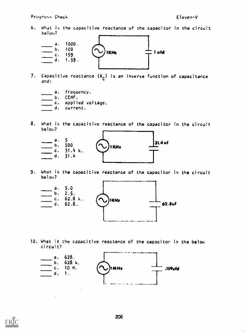
Progress Check Eleven-V
6. WhJt is the capacitive reactance of the capacitor in the circuitbelow?
a. 1000_b. 100
c. 159..
d. 1.59.
ufd
7. Capacitive reactance (X C) is an inverse function of capacitanceand:
a. frequency.b. CEMF.c. applied voltage.d. current.
8. What is the capacitive reactance of the capacitor in the circuitbelow?
a. 5
b. 500c. 31.4 k.d. 31.4
9. What is the capacitive reactance of the capacitor in the circuitbe l ow?
a. 5.0b. 2.5..
C. 62.8 k.d. 62.8.. 62.8uf
10. What it the capacitive reactance of the capacitor in the belowcircuit?
a. 628_b. 628 kc. 10 M._
d. 1
208

Pf.qre,.., CheckElevenV
11. CapaLitive reactance i5 the opposition a capacitor offers to:
-a. a change in current.b. a change in voltage.c. alternating current.d. direct current.
4. 4 .
. 49
BEST COPY AVAILABLE
209
Progress Check Eleven-VI
PROtiRESS CHECK
LESSON VI
Phase and Pol.er Relationships
1. Capacitance is the property of a circuit that opposes a changein:
a. current.b. voltage.c. resistance.d. capacitive reactance.
2. The plates of a capacitor are separated by a:
11111MMIN=Olb
a. wire.b. coil.c. semiconductor.d.
3. When a voltage changing at the ra e of 1 volt per secondcauses a charging current of 1 amp to flot , the capacitanceis equal to 1:
a. henry.b. ohm.c. coulomb.d. farad.
4. In a purely capacitive circuit, with current as a reference,where does the voltage vector lie?
a.+900
b. -90°-----c. -2700
d. +1800
5. In a purely capacitive circuit, the power dissipated is:
1MIMI11
a. 0.707 of instantaneous power.b. th, ,roduct of current and voltage.
d. al' legative.
210

Progress Check Eleven-VI
6. In an AC capacitive circuit, the current:
a. is in phase with the voltage.b. lags the voltage by 90c. leads the voltage by 90.d. lags the voltage by 180 .
211

Progres Check Eleven-VII
PROGRESS CHECKLESSON VII
Capacitor Design Considerations
I. An advantage of the rotor-stator type capacitor is that itscapacitance:
a. is of very large value.b. may be varied over a prescribed range.c. is of very small value.
2. Polarity must be observed in the wiring connection ofcapacitors.
a. ceramic.b. trimmer.c. variable.d. electrolytic.
3. What type of capacitor is considered to be self-healing?
m a. Oil.b. Electrolytic.c. Paper.d. Mica.
4. The two primary disadvantages of electrolytic capacitors arethat they have a low-leakage resistance and they are:
a. polarized.b. self-healing.c. very expensive.d. highly inflammable.
212

LESSON 1
PROGRESS CHECK ANSWERS
MODULE ELEVEN
LESSON III
1. c 12. b
2. b 13. b
3. c 14. a
4. b
5. a LESSON IV
6. d 1. b
7. a 2. c
3.LESSON 11 4. b
1. c 5. b
2. b 6. a
3. a 7. a
4. d 8. a
5. d 9. d
6. b 10. b
11. c
LESSON III 12. d
1. b 13. d
2. d 14. d
3. b 15. a
4. c
5. d LESSON V
6. d 1. c
7. b 2. b
8. b 3. a
9. a 4. d
10. a 5. d
11. b 6.
7. a
213
(Cont'd)

PROGRESS CHECK ANSWERS MODULE ELEVEN
LESSON V (Cont'd)
8. a
9. b
10. d
11. c
LESSON VI
1. b
2. d
3. d
4. b
5. c
6. c
LESSON VII
1. b
2. d
3. a
4. a
IF YOUR ANSWERS ARE ALL CORRECT, YOU MAY TAKE THE MODULE TEST. IF NUT,
STUDY ANY OF THE OTHER RESOURCES AVAILABLE FOR THIS LESSON BEFOkE TAKING
THE PRMESS CHECK AGAIN.
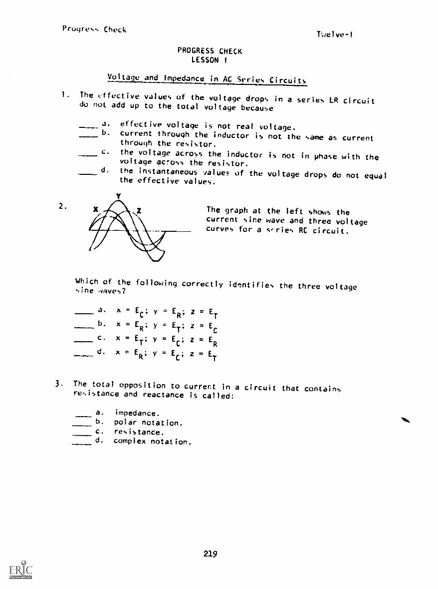
Pruyres-. CheckTwelve-I
PROGRESS CHECKLESSON I
Voltage and Impedance in AC Series Circuits
1. The cffective values of the voltage drops in a series LR circuitdo not add up to the total voltage because
2.
a. effective voltage is not real voltage.b. current through the inductor is not the same as current
through the resistor.c. the voltage across the inductor is not in phase with the
voltage across the resistor.d. the instantaneous values of the voltage drops do not equal
the effective values.
Y
The graph at the left shows thecurrent sine wave and three voltagecurves for a series RC circuit.
Which of the following correctly id'ntifies the three voltagesine 4ave s?
a. x=EC' y=ER' z=ETb. x=E
R'y=-E
T'z = EC
c. x=ET'y=E-
C'z= E
R
d. x=ERey=E-
C'z= E
T
3. The total opposition to current in a circuit that containsresistance and reactance is called:
a. impedance.b. polar notation.c. resistance.d. complex notation.
219

Progress Check Twelve -I
4. in a reactive circuit, the total opposition to current flow is:
a. Rt
.
b. XIt
.
c. 21.#
d. X .
---- CT
5. Impedance is 'he opposition that an AC circuit offers to:
a. a change in current.b. a change in voltage.c. frequency variations.d. current.
6. The vector -,um of resistance and reactance in a series FL circuitis:
a. reactance.b. inductance.
c. capacitance.d. irpeJance.
7. In a circuit that contains reactance and resistance, the totalopposition t..) current is called:
a. complex notation.b. impedance.c. resistance.d. polar notation.
8. What is the phase relationship between voltage and current inan AC series resistive circuit?
a. E leads I by 900.
b. I leads E by 9e.c. "i lags E by 90 .
d. 1 and I are in phase.
220
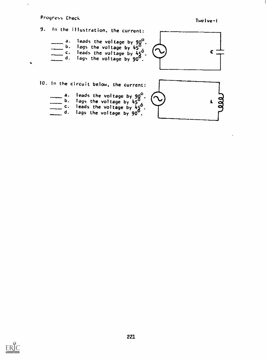
Progress Check
9. In the illustration, the current:
a. leads the voltage by 9e.b. lags the voltage by 45 .
c. leads the voltage by 4g°.d. lags the voltage by 90 .
10. In the circuit below, the current:
a. leads the voltage by 9g °.-b. lags the voltage by 45c. leads the voltage by 4g .
d. lags the voltage by 90 .
221
Twelve-I

Progress Check Twelve-11
PROGRESS CHECKLESSON II
Vector Computations
1 The magnitude of the vector shown below is and itsstandard direction is
a. 15°, 25b. 25°, 1g
c. 25, 15d. 15, 25°
..ty/1.
2. The tangent of the angle for a total voltage vector is equalto:
a.
c.
EL
ET
R
XL
b.
d.
EL
ER
XL
3. The ratio of inductive reactance to impedance is equal to:
11.1
a. TAN l-b. SIN /c. COS 7-70. /..
4. The cosine of the phase angle in a series circuit can be foundusing:
a. ELand R.
b. XL and Z.
c. ER and ET.
d. R and XL.
222

Progress Check
5. Find the impedance of the circuit.
a. 200b. 600..c. 400d. 450.=1..
Twelve-11
6. What is the applied voltage in the circuit below?
I.mMINNIrefIdee
a. 6 vb. 8 vC. i0 vd. 14 v
Find the impedance.
a. 300b. 424.
c. 600_d. 900..
By
223
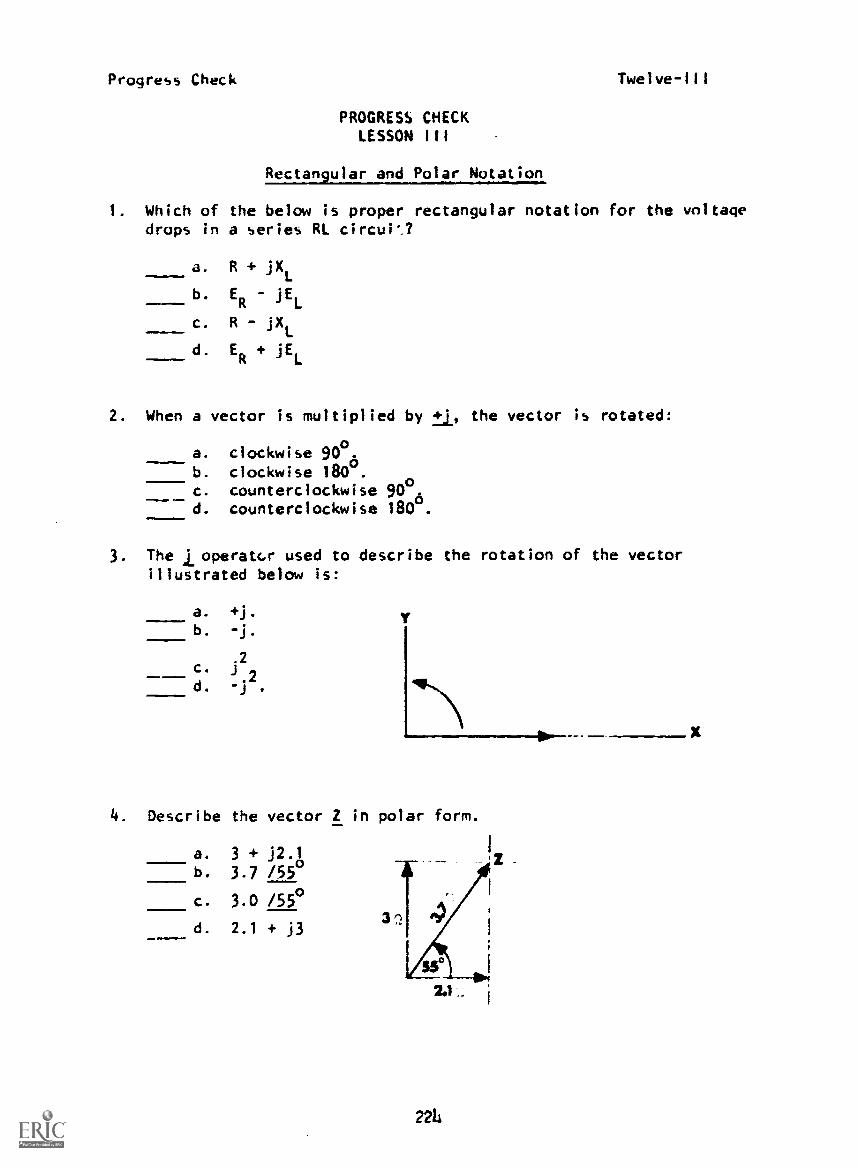
Progress Check
PROGRESS CHECKLESSON III
Rectangular and Polar Notation
1. Which of the below is proper rectangular notation for the voltagedrops in a series RL circuP.?
a. R + jXL
b. ER
jEL
c. R - jX
d. ER+ jEL
2. When a vector is multiplied by 21., the vector is rotated:
a. clockwise 900.b. clockwise 1800.c. counterclockwise 80
o
d. counterclockwise 180 ..1.1.111!
3. The j operator used to describe the rotation of the vectorillustrated below is:
a. +j.
b. -j.
.2c. -
d. j
4. Describe the vector Z in polar form.
a. 3 + j2.1
b. 3.7 /550
c. 3.0 /550
d. 2.1 + j3
2214

Fruqress CheckTwelve-Ill
5. Divide 60 /30° by 12 /450 and express your answer in polar form.
/75°
/75°
/-15°
1-15°
a. 5
b. 72
c. 72
d. 5
6. Multiply 24 /12° by 12 /28° and express your answer in polar form.
a. 286 /40°
b. 2 /16°
c. 36 /40°
d. 288 /16°
7. If1
= 12 + 118 and Z2
= 13 - j2, what is theT
of the two inrectangular form?
a. 30 /33°
b. 25 + j16c. 1 + j20d. 30 /57°
8. The total voltage in the below circuit is:
r_r-v-v-Nr
10V ±20V
a. 20 j30b. 30 + j20c. 30 - j20d. 30 + j90
isv
225
2SV

Progress Cheek Twelve-1 I I
9. Find I T' / and PF.
IT
I. =
PF
4
Ji
.ff)af
.1.1 flip
226
Pr,igress CheckTwelve-IV
PROGRESS CHECKLESSON IV
Voriational Analysis of Series RL Circuits
1. If the frequency applied to an inductor is doubled, the currentthrough the inductor wilt:
J. lead the voltage.b. be in phase with the voltage.c. be reduced by one-half.d. be doubled.
2. If the resistance is increased in a series RL circuit, the Cir-cuit phase angle will:
.mam=1....a. increase.b. decrease.c. remain the same.
XL
d. equal
3. If the applied frequency is not changed but the inductance ina series RL circuit is increased, the current will:
a. remain the same.b. increase.c. decrease.amamligMiln
d. equalEL .
COS I-
4. If the frequency applied to a series RL circuit is increased,the circuit phase angle will:
a, increase.b. decrease.c. remain the same.
Ea
d. equal ------COS /
227
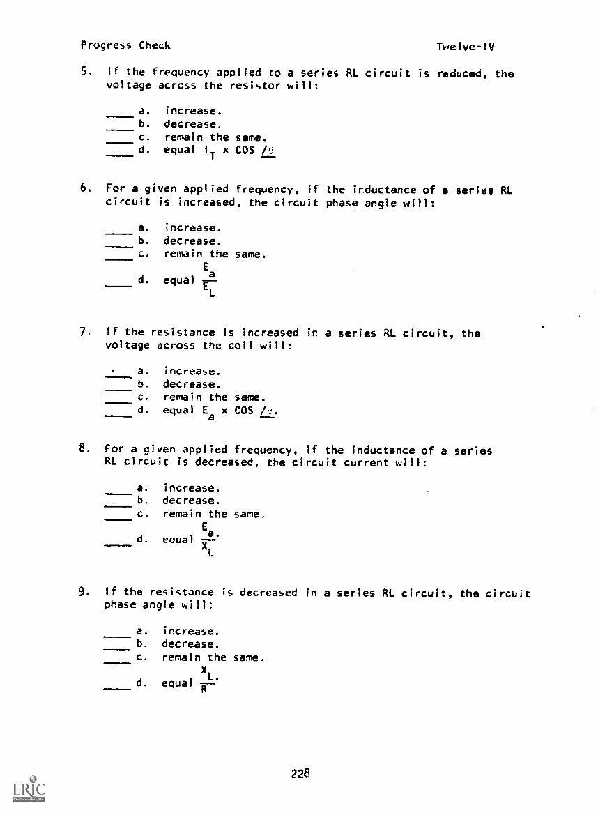
Progress Check Twelve-IV
5. If the frequency applied to a series RL circuit is reduced, thevoltage across the resistor will:
a. increase.b. decrease.c. remain the same.d. equal
Tx COS i
6. For a given applied frequency, if the irductance of a series RLcircuit is increased, the circuit phase angle will:
a. increase.b. decrease.c. remain the same.
Ea
d. equal r.L
7. If the resistance is increased ir a series RL circuit, thevoltage across the coil will:
.111111
a. increase.b. decrease.c. remain the same.d. equal Ea x COS kJ.
8. For a given applied frequency, if the inductance of a seriesRL circuit is decreased, the circuit current will:
a. increase.b. decrease.c. remain the same.
Ea.d. equal I)
9. If the resistance is decreased in a series RL circuit, the circuitphase angle will:
a. increase.b. decrease.c. remain the same.
d. equal
XL.
228

Progress Check Twelve-IV
10. In an inductive circuit, if the frequency is decreased, the cur-rent will be:
a. increased.b. decreased.c. unaffected.d. squared.
11. If the frequency applied to a series RL circuit is decreased,the circuit phase angle will:
a. increase.b. decrease.c. remain the same.
E.
equal u337,d.
12. If the frequency applied to a series RL circuit is decreased,the apparent power will:
a. increase.b. decrease.c. remain the same.
Ptd. equal Pt
13. Solve for:
a. It
b. R
e. Zt
d. /t
e. Ea
f. Pa
9. Px
h. PF
i. EL
1728wER nv
229
X

Progress Check Twelve-V
PROGRESS CHECKLFSSON V
Frequency Discrimination in RL Circuits
1. In an RL circuit, cutoff frequency is the point where thetrue power has decreased to half the maximum power and:
a. X --. R.
b. X1 = X.
c. Pt = P.
d. COS / = TAN / .
2. In the series RL circuit below, if the frequency applied is thefco
of the circuit, what is the value of XL?
AAAa. 100 ohms. ,
NOMMIe.m
.11.11
b. 159 ohms.
c. 1 Kohm.d. 2 Kohms. 159mb
3. Match the output connections with the circuit function:
a. High frequency discriminator to
b. High pass filter to
c. Low pass filter to .
d. Low frequency discriminator to
4. When low frequencies are to be attenuated, the output of aseries RL filter circuit should be taken from across the:
a. resistor.b. resistor and the coilc. coil.d. generator.
230

Progress Check Twelve-V
5. In the series RI circuit below, if the frequency applied isthe c
coof the circuit, what is the circuit phase angle?
a. 12 00
--b. 70670----c. 45
d. 900 .159 I§
6. What is the cutoff frequency ( fco) of the circuit below?
a. 31.8 Hz.b. 194 Hz.c. 500 Hz.d. 50 Hz.
231
41.
.318h

Progress Check Twelve-VI
PROGRESS CHECKLESSON VI
Series RC Circuits
1. If the value of capacitance is decreased in a series RC circuit,
the voltage across the capacitor will:
a. increase.b. decrease.c. remain the same.d. equal EC x COS /-.
2. When a series RC circuit is used as a high-pass filter, the
output is taken from across the:
.=11
a. resistor.b. capacitor.c. resistor and capacitor.d. generator.
3. If the value of resistance is increased in a series RC circuit,the voltage across the resistor will:
MIEMI=.!
a. increase.b. decrease.
c. remain the same.d. equal E
ax SIN /-.
4. In the illustration below, the current:
a. leads the voltage by 9e.b. lags the voltage by 45c. leads the voltage by 4g .
d. lags the voltage by 90 .
5. If a series RC circuit is used as a filter and the output is
taken from the resistor, the circuit Is a filter.
a. high frequency discriminatingb. band eliminatingc. low passd. high pass
232

Progress CheckTwelve-VI
6. In a capacitive circuit, if the frequency is increased, thecurrent will be:
a. increased.b. decreased.c. unaffected.d. reduced slightly.
7. If high frequencies are to be attentuated in an RC filter circuit,the output would be taken from across the:
a. resistor.b. capacitor.c. resistor and capacitor.d. generator.
8. If the applied frequency is unchanged, but the value of capacitanceis increased in a series RC circuit, the current will:
a. remain the same.----b. increase.
c- decrease.Ea
d. equal -cor7
9. If low frequencies are to be attenuated in an RC filtercircuit, the output would be taken from across the:
1,==.111111M
a. generator.b. resistor.c. capacitor.d. resistor and capacitor.
10. If the frequency applied to an RC circuit is decreased, thevoltage drop across the capacitor will:
a. equal Ea multiplied by COS P).
b. remain the same.1c. decrease.d. increase.
233

progress Check Twelve-V1
11. If the filter circuit below'is to be used as a low-passfilter, the output will be taken from across points:
a...-
a. A and B.b. B and C.
c. C and A.
12. If the value of resistance is increased in a series RC circuit,the voltage across the capacitor will:
a. equal I x COS /. .
b. increasi.
c. decrease.d. remain the same.
13. When a series RC circuit is used as a low-pass filter theoutput is taken from across the:
_ _ a. resistor.
b. capacitor.c. resistor and capacitor.d. generator.
14. In a series RC circuit, if the frequency of the applied voltageis decreased, the circuit current will:
Ea.
a. equal
b. increase.
c. decrease.Ea.
d. equal 37
23L

Progress Check
15. rind the impedance in the diagram shown. A XL 30
a. 50 /370 ohms.
b. 50 1-37° ohms.
c. 50 /53° ohms.
d. 50 1-53° ohms.
xc 6°
Twelve-V1
0 R40
16. In a series RC circuit, the apparent power is 265 va, the phase',Ingle is -67.6° and the frequency of the applied stage is 60 Hz.
Solve for:
a. Pt
=
b. P =x
c. PF =
235
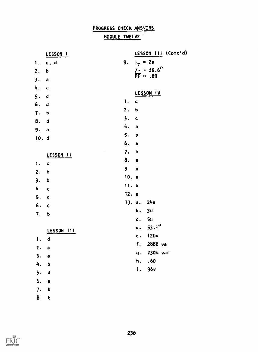
LESSON I
1. c. d
2. b
3. a
4.
5. d
6. d
7. b
8. d
9. a
10. d
LESSON II
1. c
2. b
3. b
4.
5. d
6.
7. b
LESSON III
1. d
2. C
3. a
4. b
5. d
6. a
7. b
8. b
PROGRESS CHECK ANS'ZiRS
MODULE TWELVE
LESSON III (Cont'd)
9. 1
T2a
/- 2 26.6°PI: is .89
LESSON IV
1. c
2. b
3. 4
4. a
5.
6. a
7. b
8. a
9 a
10. a
11. b
12. a
13. a. 24a
b. 3.2
C.
d. 53.1°
e. 120v
f. 2880 va
g. 2304 var
h. .60
1. 96v
236

PROGRESS CHECK ANSWERS MODULE TWELVE
LESSON V LESSON VI (Cont'd)
1. a 13. b
2. c 14. c
3. a. B, C 15. b
b. A, B 16. a. 101 w
c. B, C b. 245 var
d. A, B c. .38
4. c
5. c
6. d
LESSON VI
1. a
2. a
3. a
4. a
5. d
6. a
7. b
8.
9. b
10. d
11. b
12. c
IF YOUR ANSWERS ARE ALL CORRECT, GO TO THE NEXT LESSON. IF NOT, STUDY
ANY OF THE OTHER RESOURCES AVAILABLE FOR THIS LESSON BEFORE TAKING THE
PROGRESS CHECK AGAIN.
237

Progress Check Thirteen-I
PROGRESS CHECKLESSON 1
Solving Series RLC Circuits
1. At high frequencies, hollow tubing is used forconductors because of the:
a. effective resistance.b. proximity effect.c. skin effect.d. circumference effect.
2. What is the impedance in the circuit below?
a. 72 /-330 ohms.
b. 72 /-570 ohms.
c. 110 1-570 ohms.
d. 110 /-330 ohms.
3. If the frequency applied to a coil decreases, what will be theeffect upon the Q of the coil?
a. g, will halve.
b. Q will increase.c. Q will decrease.d. Q will remain the same.
4. In a series RLC circuit, the current will be:
a. greatest through R.b. greatest through L.c. greatest through C.d. equal in R, 1., and C.

Progress Check Thirteen-1
5. The circuit Q may be maintained at a yligh level by keepingto a minimum.
a. resistanceb. reactancec. capacitanced. inductance
6. When hollow tubing is tsed as a conductor, it is to take
advantage of the effect.
a. proximityb. skinc. Edisond. copper
7. The change in current distribution in a conductor due to theaction of an alternating current in a nearby conductor iscalled the:
a. hollow er2ct.b. tube effect.c. proximity effect.d. skin effect.
The tendency of AC conductors to carry the current on thesurface rather than throughout the cross-sectional area isknown as the:
a. hollow effect.b. tube effect.c. proximity effect.d. skin effect.
9. The resistance of coils due to proximity effect may be reduced by:
decreasing the separation betweenusing larger conductors.increasing the separation betweenadding more turns to the coil.
2142
conductors.
conductors.
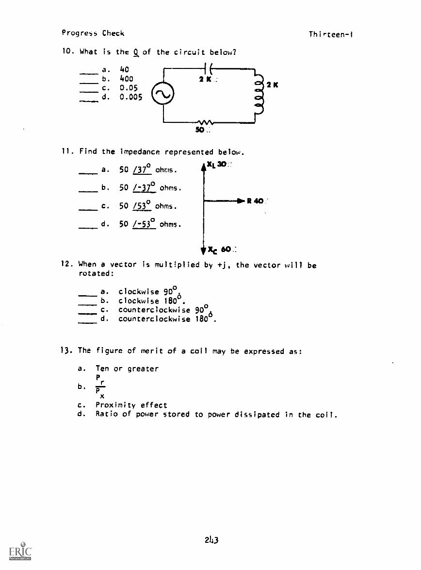
Progress Check Thirteen-I
10. What is the Q of the circuit below?
a. 40b. 400c. 0.05d. 0.005
11. Find the impedance represented below.
XL30.:a. 50 /37 ohms.
b. 50 1-37° ohms.
c. 50 /53° ohms.
d. 50 1-53° ohms.
Xc 60, :
12. When a vector is multiplied by +j, the vector will berotated:
21(
R40:
a. clockwise 90°.b. clockwise 180°.c. counterclockwise 90°d. counterclockwise 160x.
13. The figure of merit of a coil may be expressed as:
a. Ten or greater
Prb.
x
c. Proximity effectd. Ratio of power stored to power dissipated in the coil.
2143
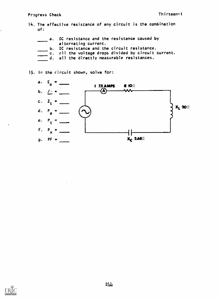
Progress Check Thirteen-I
14. The effective resistance of any circuit is the combinationof:
a. DC resistance and the resistance caused byalternating current.
b. DC resistance and the circuit resistance.c. ell the voltage drops divided by circuit current.d. all the directly measurable resistances.
15. In the circuit shown, solve for:
a. E =a-b. I-=
c. =t --
d. Pa
e. Pt
=
f. P =x --9. Pr=
211
XL 200

Progress Check Thirteen-II
PROGRESS CHECKLESSON 11
Series AC Circuits at Resonance
1. At resonance in a series RLC circuit:
a. inductance equals capacitance.b. impedance is minimum.c. current is minimum.d. power factor is 0.707.
2. In a series RLC circuit at resonance the:
a. XL
and Xc
are equal.
b. Ztof the circuit is equal to circuit R.4.111111
c. circuit current is maximum.
d. phase angle between E and I is zero.
3. The total voltage in the circuit below is
a. 31 /65°
b. 32 /25°
c. 66 /65°
d. 66 /25°
4. What is the resonant frequency in the circuit below?
a. 1 Hz.
b. 10 Hz.
c. 100 Hz.d. 1000 Hz.
2145
.159 h
volts.

Progress Check Thirteen-II
5. Determine the resonant frequency of a series RLC circuitconsisting of a 4 coil a 1.f capacitor and a 10 ohmresistor.
a. 79.5 kHz.b. 89.8 Hz.c. 628.0 Hz.d. 12.56 Hz.111-
6. If the frequency applied to a series RLC circuit is decreasedto a frequency below resonance, the current will:
a. increase.b. decrease.c. lag the voltage.d. be unchanged.
7. If the various voltage drops in a series RLC circuit are addedvectorially, the resultant will be equal to the:
a. impedance.b. reactive voltage.c. applied voltage.d. true power.
2146

Progress Check Thirteen-111
PROGRESS CHECKLESSON III
Resonance in Series RC Circ.its
1. What two points indicate a resonant circuit on the graph?
a. A and B 'Cb. C and Dc. A and C
-----d. B and D
2. Comparing the vector diagram to the circuit drawing, you canassume the circuit is operating:
a. at the upper f .
b. at resonance. Co
c. at the lower f .
co
3. When the frequency of voltage applied to a coil decreases, theQ of the coil will:
a. halve.b. not change.c. increase.d. decrease.
21.17
Progress Check Thirteen-III
4. At resonance in a series RLC circuit, current is:
a. muimum.b. limited by reactance.
c. minimum.d. out of phase with applied voltage.
5. If a series RLC circuit is operating below resonance, the im-pedance will appear to be:
a. capacitive.b. resistive.c. decreased.d. inductive.
6. If a series RLC circuit is operating above resonance, the impedancewill appear to be:
a. capacitive.b. resistive.c. decreased.
d. inductive.
7. When a series RLC circuit is operating at its resonant frequency,the impedance is equal to:
a. R jX,X
b. XL
SIN
c. Ea
x COS /-.
d. R.
When a series RLC circuit is operating at resonance, the linecurrent is:
a. lagging E.b. leading E .
c. in phase With Ea.d. minimum.
2148

Progress Check Thirteen-III
9. When the frequency of voltage applied to a coil increases, theQ of the coil will:
a. not change.b. increase.c. decrease.d. double.
10. If the frequency applied to a series RLC circuit were decreasedto a frequency below resonance, the current would:
a. increase.b. decrease.c. lag the voltage.d. be unchanged.
11. An impedance vector diagram uses what two quantities to solvefor 27
a. Reactance and inductance.b. Capacitance and reactance.c. Inductance and capacitance.d. Resistance and reactance.
12. What is the bandwidth of a series circuit if the resonantfrequency is 50 Hz and the circuit Q is 50?
a. 0.10 Hz.b. 100 Hz.c. 1 Hz.
d. 10 Hz.
13. What is the 9, of the circuit below?
a. 40b. 400
-C. 0.05d. 0.005
2149
2K I-2

Prowess Check Thirteen-111
14. If the Q of the coil in a series resonant circuit is lowered,
the bandwidth will:
a. increase.b. not be affected.c. decreake.d. equal
XL
15. When a series RLC circuit is operated at resonance, theinductive reactance will equal the of the circuit.
a. cut-off frequencyb. resistancec. impedanced. capacitive reactance
16. In a series RLC circuit, the current will be:
a. greatest through R.b. greatest through L.c. greatest through T.d. equal in R. L, and C.
17. If the half-power points of a series resonant circuit are550 Hz and 570 Hz, what is the resonant frequency?
a. 555 Hzb. 560 Hzc. 565 Hzd. 20 Hz
250

LESSON I
PROGRESS CHECK ANSWERS
MODULE THIRTEEN
LESSON II (Cont'd)
1. c 5. a
2. b 6. b
3. d 7. c
4. d
5. a LESSON III
6. b 1. b
7. c 2. b
8. d 3. b
9. c 4. a
10. a 5. a
11. b 6. d
12. c 7. d
13. d 8. c
i4. a 9. a
15. a. 150 v 10. b
b. 600 11. d
c. 20.. 12. c
d. 1125 va 13. a
e. 562.5 w 14. a
f. 974.25 vas 15. d
g. .50 16. d
17. b
LESSON II
1. b
2. a, b, c, d
3. c
4. d
IF YOUR ANSWERS ARE ALL CORRECT, YOU MAY TAKE THE MODULE TEST FOR
THIS MODULE. IF NOT, STUDY ANY OF THE OTHER RESOURCES AVAILABLE
FOR THIS LESSON BEFORE TAKING THE PROGRESS CHECK AGAIN.
$1

Progress Check Fourteen-I
PROGRESS CHECKLESSON I
Solvin for Quantities in Parallel RL Circuits
1. What is the equivalent impedance of the parallel network?
a. 15.9 ohms.b. 7.1 ohms.c. 5.5 ohms.d. 8.9 ohms.
2. If the resistance is increased in an RL parallel circuit, thetotal current will:
a. be reduced to zero.b. increase.c. decrease.d. remain the same.
3 , the inductance in a parallel RL circuit is increased, thewill decrease.
a. power factor.b. inductive reactance.c. resistive voltage drop.d. circuit phase angle.
4. Which current vector diagram is correct for the below circuit?
a.
Mt
ilL
c.
257
b.
d.

Progress Check Fourteen-I
5. What is the phase relationship between voltage and current ina parallel RL circuit?
a. I lags Ea
by 90°.
b. I
Rleads E
aby 90°.
c. IL leads Ea
by 90°.
d. I
R'I
L'and E
aare in phase.
6. Which of the following diagrams illustrates the phase relation-ship in a two-branch parallel RL circuit?
a. 91
101
b. AA
It fit
EA
I
d.
L At
fit1
c.
au low
7. In a parallel RL circuit, the applied voltage has what phaserelationship with the branch currents?
111=1
a. Ea is in phase with IL but not IR.
b. Ea
is out of phase with I
Rand IL.
c. Ea is in phase with IL and IR.
d. Ea is in phase with IR but not IL.
8. An equivalent impedance for a parallel RL circuit is valid onlyat a given operating frequency because the:
a. reactive component varies with the frequency.b. true power of the circuit is inversely proportional to
the frequency of the circuit.c. resistive voltage drop varies directly with the frequency.d. applied voltage increases as the frequency is decreased.
258

Progress CheckFourteen -i
9. What is the equivalent impedance of the parallel section ofthe below c;rcuit?
a. 4.5 ohmsb. 9.5 ohmsc. 2.5 ohmsd. 7.5 ohms
10. If the resistance is decreased in an RL parallel circuit, thetotal current will:
=0011
a. increase.b. decrease.c. remain the same.d. drop to zero.
11. When total impedance is computed, coil resistance is usuallytaken into consideration only if the g, of the coil is:
a. more than 50.b. 20.c. 15.
d. less than 10.
12. The addition of a resistor in series with the inductive branchin a parallel RL circuit will cause:
a. phase angle to increase.b. phase angle to decrease.c. true power to remain the same.d. true power to decrease.
259
Proyre ss Check Fourteen-II
PROGRESS CHECKLESSON II
Variational Anal sis in RL Parallel Circuits
1. What circuit quantity will be doubled if the frequency of the
voltage applied to a parallel RL circuit is doubled?
a. inductance.b. inductive reactance.
c. inductive branch voltage drop.J. inductive branch current.
2. Decreasing the frequency applied to a parallel RL circuit
causes to decrease.
a. I
b. Pt
c. ZT
d. In
3. Increasing frequency in a parallel RL circuit will cause IR
to:
a. remain the same.b. decrease.c. increase.
d. vary with sine of angle theta.
4. Decreasing the frequency applied to a parallel RL circuit
causes to increase.
a. I
Tb. ZT
P
d. It
260

Proyrss Check Fourteen-If
5. increasing the trequency of applied voltage will cause thecurrent through LI to:
J. increase.L. decrease.c. reoain the ,,ame.J. equal E x COS / .
6. The addition tt d resistor in ,.eries with the inductive branchin a parallel RL circuit :Jill cause to decrease.
a. phase angleb. pmier factorL. true powerd. re,..i-tine branch current
7. Increasinq the frequency applied to a parallel RL circuitcause,, to increase.
a. pha e angleb. i,-pedance
d. IL
8. Increasing the frequency applied to a parallel RL circuitcau,se, to decrease.
a.
ITc. P
IP
261
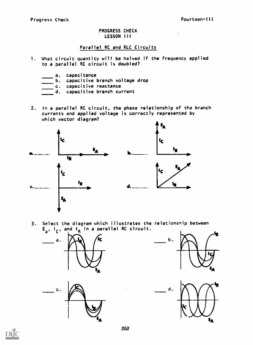
Progress Check Fourteen-111
PROGRESS CHECKLESSON III
Parallel RC and RIC Circuits
1 What circuit quantity will be halved if the frequency appliedto a parallel RC circuit is doubled?
a. capacitanceb. capacitive branch voltage dropc. capacitive reactanced. capacitive branch current
2. In a parallel RC circuit, the phase relationship of the branchcurrents and applied voltage is correctly represented bywhich vector diagram?
C.
b.
d.
IR
3. Select the diagram which illustrates the relationship betweenE. I
C'and I
Rin a parallel RC circuit.
a.
c.
262
b.
d.

Progress CheckFourteen-III
4. The total impedance of this circuit is ohms.
a. r0b. 142
c. 112
d. 71
5. Decreasing the resistance in a parallel RC circuit causesto decrease.
a. true powerb. capacitive currentc. phase angled. total current
6. if the frequency applied to a parallel RC circuit is increased,the total current will:
a. remain the sameb. increase.c. decrease.d. equal Ea x COS I.
Determine total impedance of the circuit below.
a. 175 ohmsb. 60 ohmsc. 100 ohmsd. 125 ohms R TOO
8. Decreasing the frequency applied to the circuit below willcause to decrease.
1111a. total currentb. impedancec. power factord. capacitive reactance
263

Prociress Check Fourteen-III
9. It a three-branch parallel RLC circuit is operated at a very
lc. trequency, it t i I i appear to the source.
a. capacitiveb. shortedc. inductived. re,,istive
10. In a three-branch parallel RLC circuit, if the inductive
currents and capacitive currents are equal, the circuit will
appear to be purely:400
a.
b.
c.
d.
inductive.
capacitive.resistive.react ive.
AIC
4,1/4
To.
11. In a parallel RLC circuit, if the circuit phase angle is nega-
tive. the circuit appears to the source.
a.
b.
c.
capacitiveinductive
resistive
2613

Progress CheckFourteen-IV
PROGRESS CHECKLESSON IV
Parallel Resonance
1. At resonance, the impedance of an ideal parallel LC circuitis:
a. maximum.b. capacitive.c. inductive.d. minimum.....1111altea.
2. Increasing from resonance the frequency applied to a parallelLC circuit causes the current drawn from the source to:
a. appear inductive.b. decrease.c. increase.d. lag the voltage.
3. If an ideal parallel LC circuit is at resonance and XL
is 2000ohms, what is the value of X ?
a. 1000 ohmsb. 4000 ohmsc. 2000 ohmsd. 20 Kohms
4. Determine the resonant frequency of the circuit below.
a. 1 KHzb. 10 KHzc. 100 KHzd. 1000 KHz 159inh
5 One indication that a two-branch LC circuit is at its resonantfrequency is maximum:
a. line current.b. resistor current.c. phase angle.d. impedance.
265

Proyre's Check Fourteen-1V
6. Decreasing the frequency applied to a parallel LC circuit
from resonance causes current drawn from the source to:
a. lead the voltage.b. decrease.c. increase.d. appear capacitive.
7. If a three-branch parallel RLC circuit is operated above its
resonant frequency, it will appear to the source.
a. inductiveb. resistivec. opend. capacitive
8. To determine the resonant frequency of the circuit below, thevalues of must be known.
a. R and Lb. 17 and
c. C and IT
d. applied frequency and
266

Progress Check Fourteen-IV
9. After the source of power is removed, the current will continueto circulate back and forth between the inductor and capacitorat a diminishing rate. This action is known asaction.
.1110.111.
a. LC
b. flywheel
c. circulatingd. damped wave
S
10. A damped wave is caused by thepractical circuit.
a. resistanceb. capacitancec. inductanced. current
267
present in any

Prugress Check
PROGRESS CHECKLESSON V
Effective Resistance in RL Circuits
Fourteen-V
. If the Q of the coil is greater than 10, the effect of R2 onthe impedance of the circuit is:
a. negligible.b. to increase impedance. 1
c. to decrease impedance.d. to double impedance.
3
2. One of the effects of a low-Q coil, compared with a high-Qcoil, in a parallel RL circuit is:
a. higher circuit current.b. lower circuit current.c. higher inductive current.d. lower resistive current.
3. Replacing a high-Q coil with a low-Q coil in a parallel RL
circuit will cause:
a. an increase in phase angle.b. a decrease in phase angle.c. no change in circuit current.d. an increase in the voltage drop across the coil.
i. A decrease in effective resistance in a parallel RL circuitwill have what effect on the voltage dro7 across the inductor?
a. no change in E
b.- decrea.e in EL
c. increase in E
L
d. E,Lwill decrease by 1/2
268

Progress Check Fourteen-V
5. Increasing Rf of the coil in a parallel RL circuit will havewhat effect on true power?
a.
b.
c.
no effectan increase in P
t
a decrease in Pt
6. If the Ref of the coil in a parallel RL circuit is increased,the power factor of the circuit will:
a. remain the same.b. increase.
c. decrease.
If you don't know what it does don't fool with it!
269

LESSON I
PROGRESS CHECK ANSWERS
MODULE FOURTEEN
LESSON III (Cont4d)
1. b 5. c
2. c 6. b
3. d 7. b
4. b 8. a
5. a 9. c
6. a 10. c
7. d 11. b
8. a
9. a LESSON IV
10. a 1. a
11. d 2. c
12. b 3. c
4. a
LESSON II 5. d
1. b 6. c
2. c 7. d
3. a 8. b
4. a 9. b
5. b 10. a
6. a
7. b LESSON V
8. a 1. a
2. a
LESSON III 3. b
1. c 4. a
2. a 5. b
3. 6. b
4. d
IF YOUR ANSWERS ARE NOT ALL CORRECT, STUDY ANY OF THE OTHER RESOURCES
AVAILABLE FOR THIS LESSON UNTIL YOU CAN ANSWER ALL THE QUESTIONS
CORRECTLY.
270--

.4
12.
Appendix
'1. 1 il, Si'
BEST COPY AVAIUMLF
it 1-, al. 2"
Fourteen
0. 3' 0 4- (1. It f "Imift
.;" (3, 13 4). '...1, at 0000 at, 001 7 0,110 4s 0. 0012 0. 0070 O. 0057 O. (1105 0. 0122 0. 0140 0 01-.71. 000 1. 0000 1. 0000 1. 0000 I 000 1. 0000 O. !3'1'/'1 11,14.1
1,81, 11.'111011 al, 11(117 13.'1045 0. 00 1.! 0, 00 ,'0 0. 0057 II. 0105 (1. 0122 0, 0140 0. 0157at all -, 1 0. 01,12 0, 02919 0. 022 0. 0244 O. 021.2 0. 027'1 0. 0297 0 0 414 0. 0 412pa -a 0, aaps pas 0. aai., ; 0. 4'a97 . 4.aq 7 0. wig,. 0. .1,011 el..i:. NI U. 0.:11'42 020" 0 0227 0. 0244 0. 021,2 0. 027" 0. 0297 0. 0414 0. (1442
0. 0 44') 0. 9 4' '. 0. 0 484 0. 0.101 0. 0419 (1. 04 10. 0. 04'34 O. 0.471 0, 04,04 0. 0;401.O. 'Vag.' (1. 11'14 al, 11'1'14 0, 91'12 0,1111 0, 9110 0.1910 9'489 0. 1988 O. '1187ail 0. 0 /11 0. 0 if 7 0. a) 3s4 0. 04(12 0. 0419 0. 04 37 O. 0454 0474 4). 048') 11. 11107
:1'.ti
1.01
Go
"01i`1.111
47;.: 4 it. 41;41 0, (119)4 (1. 0;71, O. 059 4 43. 01.10 0. 01,280. 9 91747 0, 9,1)44 0. 998 4 O. 9951 0. 41141 O. 19800. ill.: 1 II. '1"1-12 (). 11;19') 1). (1-477 e1144 0. 01.12 0. 01.24
20. 1 et 20, 0575
0. 01 '45 0. 01,4. o0. 997,1 0. 9978 0. 9977O. 01.47 0. (II,a,4 O. 0102
at ;1;4 0. 07 42 0. 0;50 U. (17t,7 0. 0785 0. 0804 0. 0819 0. 0837 0. 0/454,0. 9974 0, 997 4 0. 1,72 0. 91)71 0. 9'h,9 0. '1'43 .8 0. qqt,t, 0. 'VOA . 3:0, 011; a1, 0744 0, 0752 0, 011.9 0. 07s7 0. 0805 0. (1 )422 0. 0840 0. 0857.
1). 01SN'i 0101.ft, 114 (3 (1, 1i1111. ()Vt.! 11. 0910
O. 0924 0. 0,141 0. 09,:s 0. 09 7t, 0. 099 3 0. 1011 0, 102340. 99=47 0. aait. O. 9954 0, 99 0. ,19s1 0. 9,141 0, '19470, 0928 0. 0045 0. 091,3 0. 09)41 (1. 099)4 0. 1011 0, 10
0. 1045 0. 10..3 0. los() 0, 1047 0. 1115 0. 1134 O. 1144 0. 111.7 0. 11K4 0, 1201:O. 9941 0. 9943 O. 4942 0, 140 0. 1938 0. 11 3a, 0. 19 14 0.19 32 0.9930 O. fp121(;1). 11,`,1 U. 1410.9 0, lOs'. 0. 1104 O. 1122 O. 11 39 O. 1157 0. 1175 0. 1142 0. 1210
PI (1. 12 is, (1. 125 4 0. 1271 0, 11ss 0. 1 405 0. 1 32 4 0. 1 440 0. 1'457 0. 1474'""2 0. -a"23 0. a"21 4',19 (1. 9017 0. 94714 0. 9912 0. 9910 0. 490 . 'pow,'112s 124'. 0. 124,3 0. 1281 0. 1211 0. 1417 0. 1 114 0. 13;4 0. 14711 0. 1 3314
0. 1192 0, 1401 0. 142f. O. 1444 0. 1-41,1 O. 1478 0. 1415 O. 1513 O. 15 10 0. 15470. 9 913 O. 9100 O. 1818 0. 1895 0. 1813 O. 9890 0. ,1884 0.1;885 0..0042 0. "s1400. 140.; 11. 1424 0. 1441 (7. 145" 0. 1477 0. 14')5 0. 1512 0. 15 30 0. 1548 0. 1 it'll.0. I ,4 0. 15,L 0. 11,1 11,33 0. 16SO 1a.144 ft. 11.145 0. 1702 0. 1119:0. 9s; ; 'as ;4 0, 'Ih71 0. 'as'.') 0. 43. 'is'. 1 0. '0.0 (1 0. 9857 0.1854 0.'1315)I,,f, 0, 1 s.44 at, 1..02 0. 11 20 0. 10.35 0. 1t.55 0. 11,73 0. O. 1709 0. 1727 0. 1745'0. 1: sa. at, 1754 0. 1711 0. 1;88 0, 1340; 0. 11422 0. 1840 0. 13457 0. 1874 0. 1841
. 0. '4-44 0, 9-.45 IL 942 0, q3 4 VI 0, als at 0.1813 O. 99429 0. 9821. 0. 99424 0. 9820U, I ...3 41. 17s1 0. 1 ;11.1 (1. 1s) 7 0, 1)435 0. 1853 0. 11471 0, 13490 (1. 1908 0. 1921.
,1:11.
. I!:
10 '4 0. 1 *a2. S 0. 1',42 0. 1 'IS'. 0.' 1977 0. 1994 0. 2011 0. 2023 0. 2045 0. 20+,2it. .4,1. It. ,15121 0..141 0 0.1501. 0. 1803 0. 1711 0. 171tt O. 9792 O. 97 WI 0, q71450, 1944 it. 191,2 0 1480 0. 1'1'x34 0. 2011. 0. 2035 0. 2053 0, 2071 0. 1081 0, 210720:-# 11 401, 0, 211 5 13.4130 O. 2147 0. 211,4 0. 2181 0. 2198 0. 221S 0. 22320. 9.; -t778 0, 9774 0, 9770 . 97.,7 0, 471.3 0. 751 0. 1755 0, 1751 0. 97480, 212., 1..2 0, 21140 0, 214" 0..:217 0. 2235 0. 2254 0. 2272 0. 22q0.
t
11,
41.
11.
21.7 0. 22s4.#740 0. 974t.
127 2345
O. al" 11. 1"
(1.2300 0.2313 0.2334 0. 2351 0.231,8 (1. 2385 0. 2402'r712 0. 472,4 (3. "724 0. '7720 0. 1714 0. 9711 0. '1707
0.231.4 0.2"442 0. 2401 0.241+1 0.2438 O. 245.. 0.4475`
0. 4" 0. 3" 0. 4" 0. S"
275
0, 4," O. 7" 0. 80 0.4"

4
i 4
414
1. I
0. 4.1:0
, 1,,
-.4
..4 ir4
10 4, It
I.; "
it I: 4-,it 4; -2
tr, 40, 4
4. 4
0. 15- 4- -
It .4 1,,-nal
, 4., ',t.
.1 . tr. 2" 0, 4 Ii 4 14 .4" 41. ." ;" 41. M" 41. '4"
Fourteen
4 ." 11.
4. r a
a, 41. 4
0 2.4:01 la:
11. .4
00 '4. hr
'I
0 2..1.40, '4, r 1
0,4. 'It ; ,
P', 0. .1"
41.
te I 4it .11's 4
11. 4. 1.4
0, 2,4441, qt.: 4
0 2'4 .441 411.4
11. it! 11, :I'l 4. it. tr, 2. :4 0 2..12 0. 1
,;* 41 If 41 :1 4.1 11. 2. -. 11 2. ;4 tl, 21.41 41, 27411. 2741/.1, . 41, 1. .11 4) '4.4. al. '4..11 4), 'If 4. 41 11..31. 0. 10. ; '11 2.! 41 ;
it th al. :I; 0. 2:st 11. i 11. Za..e.f. ti. Z411 0. 2430 0 24.4'3
". 0. .40 :%.! 4), 4-44(1 (I. -4") ." (1. 2*, ."4 0. 24041 tr. 2'01;
tr. 0.104, tr, 0, 4,1 0 41, .441,4,4 41, '104 4 (4. '4'17h 11, '4 7 t 0. 't-at.`,.
11.
...Lit)
0, 2.01,
;
0, 2.'24
20;4
0, 20.44
41. 2,4 10
I), .'11,4
0, 40117
0, 2.441
0. 40.!.1
0, 300 0
11. 4040
0, '4(14' -1
11 41147
11. 4114'
tr. 30;4
1', 1.,1:1
0. 410;0, ,440,41. 42, ,a
4 42;2'1-1.1.4
11, 4.4, 4
41.
It, WA,
(I. I
4..no0. 4444
41 i:..14). .4.1.11
41. 4.444
41 11.114
(I, 311'1
41. 4440q4444
0 440;
0. istr.,.4,134
0. 404
11. '4,.14Z.
es. 4444
0, 41'0,0, q44'10, 342;
0, 44221 4 4.!
0.
0..4-14;4). 4I-,4
0. 117341. '144 40, 44.4.,
t1, Si is0. .1.124,
4.441
0, 0.442II 4172
31, 41'300, 44;40. '43..31
41, 4371..
0, ,14210. 4.4.1
tr,WI;
0. 3203,0..14724t, 3 445
O. 33710. 441 441. 34041
0, .44210, 4,.11
0. 422 30. 04i,141 3404
0. 3 14;O. '14000. 34,4111
4),.4;31.,0, 4240
0. 124'30. 04..30, 1424
11, 14414u. '440'441.
0, 44 4; It, 34,34 O. 4+,0 11, in,f. 44, 4,(14 4.4 M 41 3434 0, 1.443 tt, V,. 7
1.. 'I ;Aila; 4 , 4
'1 ',"%'t
0. 4. ',4I
41. 4. .4.1
0..44; 40 4;1.1
0,41 ; 4A4
4), ill41. ; -.4.4
044411 4; P4
it. '13.1140, '47,1'1
41. 'a 4420. 4'14 (1
tl, is 1111 (1, 4,1, 0 4, 44 44. 41.40 0. tr, 41,.41 0. 31,0: 41. '4714 4". 30
11. .1 4 411 0. .442, 4 4). '141 ; t4, '1411 0..4404 0, 42404. 0. 121 0. 02 145 41. 0.! ;14
'' 4-,..t 41. 4 - ;'4 (4. 44...1 0. 4.14.4 0, 40 4) 40-0 O. 3'17'1 41. 40110 O.
0 1.* .!1..'_1
11. i;:N11,
0. 47'),+4 °44
0. 441 1 0. 4427q4 4.,
0. 44..430,
O. 3/44')0.
0. 441'4(4.
0. 4s101n. ft: I 2.
" "4"" " 0. .4101 11 4122 0 4142 0.414.4 O. 414 3 0. 4204 tt.
11. 4 t 4 0, 4140 0, 30 1 ;0;1 , .4147 0 400 4 0. 4411'4 to. 4035 O. 41141
it 44'4... 41. '41'.4 0 '114,1 0. '41:4 41. 01 11 0. 01.4 0. ,a1 s7 0, 01.01 0, 01.43
0 204 t
0,
II, 400 I
440;
0 411
0 44:7
11 41 41
0. 43 1
41. 414,
0. 4'44,')
0. 411.4
0. '1340
0. 43 ;1
0. 4411
41. 41.1..
0. 44
0, 4.1.10
0, 412 4 0, '41:1 41. '1114 41, .110 (I. 00 4) 0. .40mus 41,.40:44 0, '40;044; 4 41. 444.1 44, .1 41 0. 41. s n, 4,.11 0. 4.21 0. 4,,42
11, 4,2,42 41. 4:' () 42;4 0. 4...o4 u, .140-i tr. 4 421 0, 347 O. 4 4'2 0. 441.4
I1. '811,, 41, 14, .4041 41, '4114 4 0, 'MI% 0, n01 1 0. q11111 11. 49.11.
.1, 4. 14 tr. 4.14,. at. 4:27 4r 4:h II. 4'1;41 tr, 4701 0, 441 4 0. 44 14 0.
4 0, 4.11.. 0, 44 41 0. 444.. 0. 44, 2 (4, 44 ;h t4. 44'14 0. 41400 0. 4.+241
'a. 4'4'4'4
,1. S'i; 4It, 4'121
41 "1./.."1
0 4'14211. S'11117
41. 40/.ft'4,1'4
ti. 40 4..41. ,4442
0, 401404
11. 4.0 44
O. -012 'I41,
0. '14:41
11. 4011 4.
O. .,074
I 4,/112
tr 4.,;10, 111.04 4
tI. 4,4e,(1, 10141.
to, 44 0241. "OS
0, 4' 1 74). h144 ;1/
0, 4* 4411 ../.(EZ.
0, 41.4/4(I, 4.)4'14
11. 441.447.'!4.41.
it. ;'IU. Mb
it .1 ; 11. VI ti. '.144 0, "14411. 11. ',22:1 41, ,41 `1..! ;2 0.
276
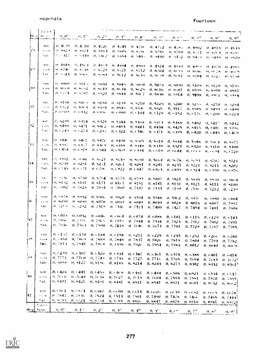
2.4
42
44
44(.15ttidi x
i1.... ft. 0 41, 1" .t. 0. 4" 4'. 4" 0, I "
0. 14 O. 4 1 it 0. 4 ;24. 4;41 0 4 :4 0. 4;72 it. 4,,1 %N.).& !,21 11. .1414 H. 0, 474-. it, 4740.. 41 a), . 4.111 0, 44 2 0, 4 414 , it. .44 44) it 44 t2
411.
. .1%
.1-,
I .u.
4.s!.
a ...
'
-'It.
4IN
t
4 4.1
II .1444 4s4 4 0. 44 -,'9 it. 4494 it 490 0 4.424 0. 49 49ii -.744 0, s; 44 4;29 0. 4 ;21 0, 14';414 54.',
.4 4 O. I. 0, I-is.4 Ii. 41.12 44 41. 114 -04 (1. 134.41
-1111141 0, -011 -I4.
;07
I), hit 40 (14.4 0. 4114.11 0. 14()711 4). 111'4414). 4.4 i 84,'44 4). 44.24 0, 414, it. 44.070. 4.4'0 0. 4444 0 44 7 0, 44.4(1 0. 4914
It. 4i ,fi It. 41f fi, -.1640 0, -0 1.#
''Nq i O. 4444 0, 84440. ttiot . , 32 41, 4,41411 0, , 040
0, 4210 O. 51.24 0, 240:"6 it, 0. 4,2I. 0. nst.;
0. 104 1.142
4299 0. 4 414 11. 42'4 0. 4 144 4). 4144 O. .'4.47 4 11. 4 4r1140. 4440 it. 4471 0. 844 2 0, 4443 0. x444 O. 4434 0, 44250, 249 It .27.4 0,4.29; 0.4,322 0.4.344, 0. i71 4.494
9444 H. 444 1 41, 4474, o. 440 0. 4,04 0. 4419 0. 44141. 4 141- 11, n 'I, 7 it X if 4 11. .VO4 II, 4414 14 4 49 41. 4 41')I), 4',4 0,0419 0,1,444 0,4,41,9 o 4.14 0.4 f .1'1 ci.44
-4492 H. .4.14, Ii, 444121 0, M4,3,11 m4441 II. 442411 0. 42. : 1 0, S14,1
;-I3 0. , I 0 ;qt. t), M22
Fourteen
4). ;" M"
4411: II 48140. 4, :1 (I
0. 44 ; it. ,t44
0. 494, 0.0. 44,54, 41, -.4 :!'4,
4), 4704 0,
0. 51114 11:41$499 it. 4490
O. 4944 0. 494:1
41.4"
0, 424-. 0, .2701405 0 84.1,4
it. 174. 4). 200
41, '1402 0. S41-0. 4414 0. .440,(1,4,420 0, 4.444
0, 4.444 0. '0,4.30. 5 4241 MiloO. 4.1 H. .-4.1
O. 't.f.n40 4440O. 1.22.4
0. 44 320, 44'4f.0.4 4.9
4). 447 7a, 434t4t
1724
O. r,,,A0 0, 41d1 51,78 II. P'4, J. 470; (4. 472 10. 4241 0. 4241 0. N.! 41 0. ',221 0. 14:11 0. 42020.4.44; it. (.4', 4 0. (.499 it. I 4424 t1, #,45(1 0, 4.474,
44. 1.,. 411 O, s';,4 O. 47:9 0. 4.''12 0, 5807 0. 4421 0. 4454 0. '04-10 444..I42 H. s141 0. 4171 0. 411.1 0 4141 0. 8141 O. 41 41 0. 4121 O, 4111 0. 4100
:002 0. 7itzs 4). 70,4 H. 7 4150 0. 7107 0. 71 43 0. ;149 0, ;144- 0. 7212 O. ;2 49
0, 4492 0. 404. 0. 4920 0. 49 14 0. 444 0. 404.2 1). 497 O. it44'o (4. 004H 1040 U. 4070 41. 4441-04 O. 4049 0. tt1039 0. /10:.$ 0. 14018 0. 4007 0, 7997it. :22 O. ;119 0. ',".444 0. 7373 0. 740a 0. 742; O. 7444 it. 7441 0, 7s044
0...042 4).1.044. O. 0. 4) 0. 1 074 0. 4.044 0...101 0. #.114 0, ..124 0.1,1430. 474 . it. ;4t, 0. ;944 0, 7934 0. 7924 0. 4912 0. 7901 0. 7491it. 759,1 it. 7490 it, 7614 ;,44, 7,73 0, 7701 O. 7729 O. 7;47 0. 77144
0. a 1 (1. '170 0.4.144 0,4.3144H. ti%st/ 0, 744,9 O. :449 a. ;4441, :41 4 0, :41 4'. 744.9 0, ;4914
,it{ 0.4 42S4,.1 1). 71 /
'All. tt.Y, j'
st.t: 0.:44;
'4
4). 21 1 .4,225 44. t 23') 0,4 242 0. i 2,4, 0, 1,4400. 74 37 9, 714244 4t. 7414 0, ;404 0. 779 1 0, 7 ;M211, 792. 0. 7944 4). 794 1 (1, 4011 0. 40441 a. 404 9
it. 1 31)7 0, 4,311 0. i.i 54 O. - 347 0. 4, 3..l 0. 4,374 0. .384 0. 4.401 0. ,414it, 774.0 O. 7;49 11, 77 34 0. 7727 O. 771, 11. 7704 0, 74,04 O. 74,43 O. ;I.:2'0. '4127 it. 4144, 0. 4144 0, 4214 0. 4141 0. 4274 0. t4302 0. 4432 0, 43441
0., 441 0.4.4;44 0. t44.44), 74,49 0. 7 is 0, 7.270. 4421 0. 4441 0. 4441
0, .441 0. 04,44 0.4,4(04 0.4.421 0. 4.444 a, 4,'.17-;4.I 0.' ;1,04 0. 7494 0. 7441 0. 7470 it, 74;49'
0, 4411 0. 4441 it. 4471 n, 44,01 O. N4r34 11, ht.4.21
4.,;.1 0. 4,'1S; 0, 14.00 O. ",1 3 O. O. 4') t.,44 0, I,f.S0.7413 0, 7401 0. 7490 0, 4). 741.1, 0. 7444 0. 744 41,
0. -, :24 it. x ; '14 II. 54 4814. (4. 8441 4). 1i478 ii, S'11(1 1), 4941 it,
(1. 2" 0. i" 0. 41' 43, 0,4" 0, 7° 0. s"
277

Appendix
12,4
31411q
142
:43
44
44.
14
49
50
52
-53
'54
billI gifi
tan
Gob
tan
tan
8211
I OM
tan
bill09
tan
NISI
c urg
Ian
<<.stan
8111
tan
1211
1,14tan
bill08
tan
oin
Ian
din4 115
tan
Sin1118
tan
sin44,8tan
fundIlion
Fourteen
11
O.
0. 74 11O. "004
0. 1"
(1..704O. 74200. 90 34.
0. 2"
0.4,717O. 74080. 904.7
3" 0. 4" O. 4" 0. I," 0. 7' N"
0...730 O. 743 O. b754, 0.1,769 0.4,742 0.4,7940. 739b 0. 7 384 0. 7373 0, 734,1 0. 7 34') 0. 7 3370 904,1 0. 91 41 0. 911.1 0. 9195 0. 9248 0. 941.0
O. d440 O. 4,1443 0..0844 0.1,8514 0.4,1471 0.1.884 0. 40494, 0.4,90'1 0.4,921O. 7114 0. 7302 O. 72'10 0. 7278 0. 72.4, 0. 7444 0. 7242 0. 7230 0. 72180. 9125 O. 9348 0. 9 4'11 0. "424 0. "447 0. "490 0. 9523 0. `3S5o0 0. 9590
0.1.94 7 0.1,959 0.1,972 0.1,944 0..,9,47 0. 7009 O. 7022 O. 7034 0. 704e,0. 11,44 0. 7181 0. 714,9 O. 7157 O. 7145 0. 71 33 O. 7120 0. 7108 0. 70,0. 94, 47 0. 91,441 0. 9725 0. 9759 0. 9193 0. 9827 0. 9144,1 0. 9149., 0. 99 40
0. 7(171 4). 7084 O. 7091, 0. 71118 0. 7120 0. 7133 0. 7145 0. 7157 O. 711,9O. 7071 O. 7059 0. 7046 0. 7034 0. 7022 0. 7009 n.4,997 0...984 0. ,,9721. 0000 1. 00 35 1. 0070 1. 0105 1. 0141 1. 0174. 1. 0212 1. 0247 1. 0284
0. 7193 0, 7201, 0. 72114 0. 7130 0. 7242 0. 7254 0. 724.4. 0. 7278 0. 72900..,947 0. 4.434 0. 40421 0. 4,909 0. 4,8'4e. 0.1,8144 0. 4,871 0.4,1448 0. /04441. 01515 1. 0392 1. 0428 1. 044 1. 0501 1. 0538 1. 0575 1. 04,14 1. 04149
0. 7314 0. 7325 0. 7337 0. 7349 0. 7361 0, 7373 0. 73/45 0, 7 396 0. 74080. 4,1440 0...807 0. !.7914 0.1,742 0.4,74,9 0,1.7% 0..,743 0.4.730 0.4.7171. 0724 1. 07..1 1. 0799 1. 0837 1. 0875 1. 0913 1, 0951 1. 04190 1. 1028
0. 7431 0. 7445 0. 7455 0. 7441e 0. 7478 0. 7490 0. 7401 0. 7 413 0, 75240. 1.4,91 41..78 0. 4,1,64 0.4,4,52 0...4.39 0. be.26 0. 1.4,1 3 0..,1.00 0. 1.51471,110b 1.1145 1.1184 1.1224 1.12b3 1.1303 1.1343 1.1383 1.1423
41. 7547 0.7559 0.7570 0.7581 0.7593 0. 71.04 0.74.15 0.74.27 0.74,380.4.54,1 0.4,547 0. (.534 0.11521 0. 1.5014 0.1,494 0.41481 n.1.41,14 0.1.4551. 1504 1. 1544 1. 14145 1. 1141. 1. 14,1.7 1. 1708 1. 1750 1. 1792 1. 1833
74,4,0 0. 7..72 0. 7043 0. 7..94 0. 7705 0. 7714. 0, 7727 0. 7738 0. 77490.1.4214 0. b414 0.1,401 0.1.388 0.1,374 0.1.34,1 0.1,347 0,4,334 0.1.3201. 118 1. 191.0 1. 2002 1. 2045 1. 20814 1. 41 31 1. 2174 1. 2218 1. 221.1
0. 1771 O. 77142 0, 7793 0. 71404 0. 7814 0. 7824, 0. 71437 0. 78414 O. 714590.1,293 0...2140 0.1.41,1, 0.1,252 0.1,23') 0.1.225 0.1,213 0.6198 0.4,I1441. 2349 1. 4393 1. 2437 1. 2482 1. 2527 1. 2572 1, 24.17 1. 2111,2 1. 2708
0.7880 0.78'11 0. 7902 0. 7912 0. 7923 0.7434 0. 7944 0.7955 0.74650. 4.157 0. 1.143 0. 4.129 0. 1.114 0. 4.101 0. 4.01414 0...074 0, 4,01,0 0. 4,0461. 27'19 1. 2841. 1. 2892 1. 29314 1. 2945 1. 3032 1. 307" 1. 3127 1. 3175
0.79144, 0.7997 0. 14007 0.140114 0.140214 0.14039 0, 8049 0. /4059 0. /4070O. 4.018 0. 4,004 0. 5990 0. 5976 0. 59f,2 0. 5948 0. 5934 O. 5920 0. 590.,1. 5270 1. 3319 1. 33t,7 1. 341t, 1. 3465 1, 3514 1. 354,4 1. 3613 1. 3663
O. 8090 0. 8100 0. 8111 0,14121 0. 8131 0. 8141 0.8151 0. 814,1 0. 81710. 5878 O. 58e4 0. 5850 0. 5835 0.51421 0.4807 0. 5793 0. 5779 0.571.41. 37e,4 1. 31414 1. 384,4 1. 391., 1. 39.,8 1. 4019 1. 4071 1. 4124 1. 4176
0. 14192 0. gm 0. 8211 0. 8221 0.14131 0, 14241 0. 8251 0.14261 0. 82710.5736 0.5721 0.5707 0.51,93 0.5(.78 0.51,1,4 0.5650 0.5635 0.56211. 42141 1. 4335 1. 431414 1. 4442 1. 4494, 1..1450 1. 4605 I, 4.65'1 1. 4715
0. 0" 0. 1" 0. 20 0. 3" 0. 4° 0. 5° 0. (," 0. 7" 0. 4"
278
O. 9"
0.4.8070. 7320. 949
0..,9340. 7204,0. 9:,2 3
O. 1059O. 70830. 994,5
0. 7181O. 4,9591. 0 319
(1. 7302O. 4,8331. 01.86
0. 74200. 1.7041. 104,7
0. 75360.4.5741.14b1
0.71,490. 64411. 1875
0, 774,040.4.3071. 2305
O. 78(.90.4,1701. 2753
0.7971.0, 1,0321. 3222
0. 140800. 58921. 3713
0. 810.47501. 4229
0. 82810.51,061. 4770
0.9'
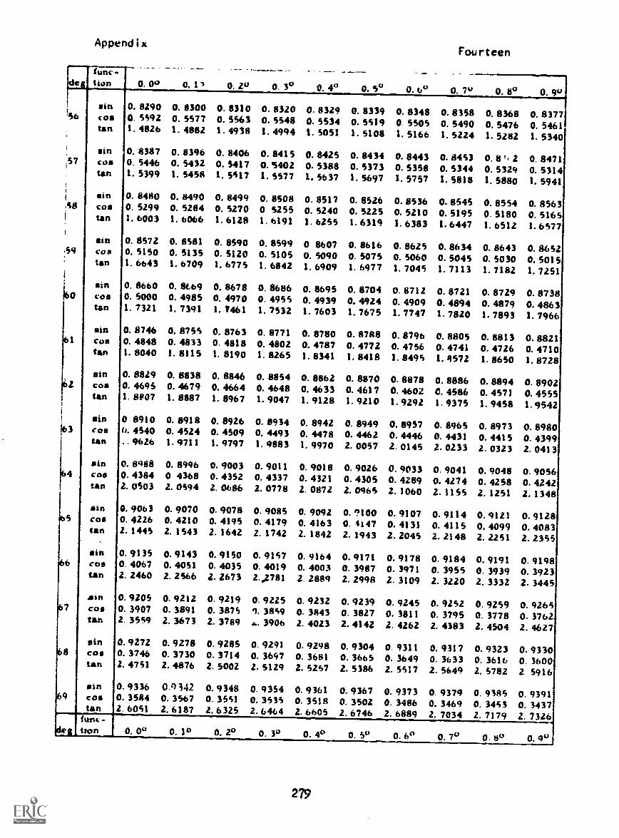
Appendix
itifIC
tIon 0. 00 0. 11 0. 2° 0. 3° O. 4° O. 3° 0. 6°
Fourteen
O. 7" 0. 8° 0. 9"sin 0. 8290 0. 8300 0. 8310 0. 8320 0. 8329 0. 8339 0. 8348 0. 8358 0. 8368 0. 837756 cos 0. 5392 0. 5577 0. 5563 0. 5548 0. 5534 0. 5519 0. 5505 0. 5490 0. 5476 0. 5461tan I. 4826 1. 4882 1. 4938 1. 4994 1, 5051 1. 5108 1. 5166 1. 5224 1. 5282 I. 5340sin 0. 8387 0. 8396 0. 8406 0. 8415 0, 8425 0. 8434 0. 8443 0. 8453 0. 8*. 2 0. 8471S Co. 0. 5446 0. 5432 0. 5417 0.5402 0. 5388 0. 5373 0. 5358 0. 5344 0. 5329 0. 5314tan 1. 5399 1. 5458 1. 5517 1. 5577 1, 3637 1.5697 I. 57 57 1. 5818 1. 5880 I. 5941sin 0. 8480 0. 8490 0. 8499 0. 8508 0. 8517 0. 8526 0. 8536 0. 8545 0. 8554 0. 856358 COS 0. 5299 0. 5284 0. 5270 0 5255 0. 5240 0. 5225 0. 5210 0. 5195 0. 5180 0. 5165tan 1. 6003 1. 6066 1. 6128 1. 6191 1. 6255 1. 6319 1. 6383 1. 6447 1. 6512 1. 6577sin 0. 8572 0. 8581 0. 8590 0. 8599 0 8607 0. 8616 0. 8625 O. 86 34 0. 8643 0, 865259 COM 0. 5150 0. 5135 0. 5120 0. 5105 0. 5090 0. 5075 0. 5060 0. 5045 0. 5030 0. 5015tan 1. 6643 I. 6709 1. 6775 1. 6842 1. 6909 1. 6977 I. 7045 1. 7113 I. 7182 1, 7251sin 0. 8660 0. 8669 0. 8678 0. 8686 0. 8695 0. 8704 O. 8712 0. 8721 0. 8729 0. 8738Co. 0. 5000 0. 4985 0. 4970 0. 4955 0. 4939 0.4924 0. 4909 0. 4894 0.4879 0.4863tan 1. 7321 I. 7391 I. 7461 1. 7532 1. 7603 1. 7675 1. 7747 1. 7820 I. 7393 1. 7966sin 0. 8746 0. 8755 0. 8763 0. 8771 0. 8780 0. 8788 0. 8796 0. 8805 0. 8813 0. 8821
621
Co. 0. 4848 0. 4833 0. 4818 0. 4802 0. 4787 0. 4772 0. 4756 0. 4741 0.4726 0.4710tan 1. 8040 I. 8115 1. 8190 1. 8265 I. 8341 I. 8418 1. 8495 1. 9572 1. 8650 1. 8728sin 0. 8829 0. 8838 0. 8846 0. 8854 0. 8862 0. 8870 0. 8878 0. 8886 0. 8894 0. 8902cos 0. 4695 0. 4679 0.4664 0. 4648 0. 4633 0. 4617 0. 4602 0. 4586 0. 4371 0. 4555tan 1. 8E/07 1. 8887 I. 896 7 1. 9047 1. 9128 I. 9210 1.9292 1. 9375 1. 9438 1.9542sin 0 8910 0. 8918 0. 8926 0. 89 34 0. 8942 0. 8949 O. 8957 0. 8965 0. 8973 0. 8980COO 6. 4540 0. 4524 0. 4509 0. 449 3 0. 4478 0. 4462 0. 4446 0. 4431 0. 4415 0. 4399tan ..9626 1. 9711 I. 9797 1. 9883 1. 9970 2. 0057 2. 0143 2. 0233 2. 0323 2. 0413sin 0. 8988 0.8996 0. 9003 0. 9011 0. 9018 0. 9026 0. 9033 0. 9041 0.9048 0.9056cos 0. 4384 0 4368 0. 4352 0. 4337 0. 4321 0. 4305 0. 4289 0. 4274 0. 4258 0.4242tan 2. 0503 2. 0594 2.0686 2. 0778 2. 0872 2. 0965 2. 1060 2. 1135 2. 1251 2. 1348
cosgin 0. 906 3
0. 42260. 90700. 4210
0. 90780. 4195
0. 90850.4179
0. 90920. 4163
0. ?1000.$147
0.91070. 4131
0.91140.4115
0. 91210. 4099
O. 91280. 4083tan 2. 1445 Z. 1543 2. 1642 2. 1742 2. 1842 2. 1943 2. 2045 2. 2148 2. 2251 2. 2355
sin 0. 9135 0. 9143 0. 9150 0. 9157 O. 9164 O. 9171 0. 9178 0. 9184 O. 9191 0. 919866 COS 0. 4067 0. 4051 0. 4035 0. 4019 0. 4003 0. 3987 0. 3971 0. 3955 0. 3939 0. 3923tan 2. 2460 2.2566 2. 2673 2.2781 2.2889 2. 2998 2. 3109 2. 3220 2. 3332 2.3445sin 0. 9205 0. 9212 0. 9219 0. 9225 0. 9232 O. 92 39 0. 9245 0. 92 52 0. 92 59 0. 926 567 cos 0. 3907 0. 3891 0. 3875 9. 3839 0. 3843 0. 3827 O. 3811 0. 3795 0. 3778 0. 3762tall 2. 3559 2. 3673 2. 3789 A.. 3906 2. 4023 2. 4142 2. 4262 2, 4383 2. 4504 2. 4627sin 0. 9272 0.9278 0.9285 0. 9291 0. 9298 0. 9304 0. 9311 0.9317 0.9323 0.933068 cos 0. 3746 0. 3730 0. 3714 0. 3697 0. 3681 0. 366 5 0. 36 49 0. 3633 0. 3616 0. 3600tan 2. 4751 2. 4876 2. 5002 2. 5129 2. 5257 2. 5386 2. 5517 Z. 5649 2. 3782 2. 5916sin 0. 9336 0.4) 342 0. 9348 0. 9354 O. 9361 0. 9367 0. 9373 0. 9379 0.9383 0.9391cos 0. 3584 0. 3567 0. 3551 0. 3535 0. 3518 0. 3502 0. 3486 0. 3469 0. 3453 0. 3437tan 2. 6051 2. 6187 2. 6325 2. 6464 2. 6605 Z. 6746 2. 6889 2. 7034 2. 7179 2. 7326func-
idea tton 0. 00 0. 1° 0.2° 0. 30 0.4° 0. 5" 0.6° 0.7° 0.8° 0.9°
279

Appendix
SI
<
;
a'.12
1,11444
-1 11 'I It4
ei 4,. at .4 0 '141., o 1 rf. 4:. as a.1 32
0, 34, 1 16,, la. 4 4: 3 la 4''% at 4 4.!:
. .11's S F -Z 4 4
11 it (0 '4 2 0 /.4 ;...; as. L p, -3 41 ./.4 52 S a II 122 3 11. s4o 0. 31 10 0 41 , 11'3
, a 4 . '4.1 a 1 .1 .1 a s 410. I
41, a .3. a1 la o 54 . a.; II .1--4.44
(1 11 11 4t140 (I. al, WO; U. 1(1
I at: . S ft
Fourteen
41 'a-4.1..4
(1. 2,174
4. i 14,- S. 1 44.1 i. 1...2 1 4 1 1. 3 1 it o -;. 4111,
0 a .4 a - .4. 41 a; a 4 41
; 1. 2 a" al) a) 2,;.1 11 2- A 0 2-40 4) « ^44 2-.0:; 4 :2 5 4 44 3 t 7 . , 5 i a 7 3. 41 c:
0 3 4 a 8, 1; !I ....a 0 a. .: 14 a, 412. al 1, 7, 41 .aa 41 0, -II -I,
,4 ...-,,. .2 ...4, ti .'.2., i 41 .,.;(1. 0..14 - 11 .14 7.1 .4....a 'Iv 11. 21 `1
-' -1.4.-4 , -.1,1 -. t, . t 4 a 4 ;.,--,., -. -.,,4 t r di., i 4 . 414.3 t r.-, .4
It a. 4.
at .a.44444. a)
421
a. a . 0 a. 7 ; ; 0, sa O (a 4.4 (4 'a, '90
1 .1 la 4). 4',21 a4 4-,a1.4 a) 44'17 la 24-.0i -.4 4 .-1 1 4. } I 4 a" a 7 4 a;
a7'14 17467
4.14 I II 24ala!I .4; 4:- .1 441;4-
41 4.11 4I a:3-1 4;441 U -7:.4 41 17.!:, 0. -473.!
0. 4 1.31 0. 4 31-1 0 2.117 0, 2 too4 i 1 1 -1. 1 .1.2 -1 3 11A 4. 1a. 1 4 3 47,- .4.U4 4 .. 4' 2072.
0
0. .a444t
o, o.-4,211
U. 41:45,
41
0.
3, 441.3
Itt,
14,
U
5
flU
4.
141'41
:
.1 .;11-71;
4141'0,
2.1.144)
2"41.
4,4143
.4.
(1
.2;-a044211
a, -,14
3
44,
,
4, ,
a ,, 1:
CI Z a.I2 11, "1:11)4:
t
41
r ,,,13,
'a. '.4
4, :0, ?,
a0. 443 4 U
3. a=120 5 '4 34
0. it. (4
41 z.fs4
'I:44 4'. 4- 11, 41 -a 41 a:,
%.1 0, ,21.-, zi it, 4
1 131', -1. 1. 2 .1 403 -3 4 4;'4 4 4" 17 1 ;
1 1/
I .11" ti
:! I t) ia
It )7 ,4 -a; a.
:3,42- o 2..117. 7 4 1 --:
11
U
,
.4al
a'. 7 41 'a770 :al 11 '17 ;34
0. 21.1":4. ;.4-: 4
a".2 4 11 "7:, a-;,.! 0. '41% 4 I 4)
0 0 - ,1 0 .,:4 0 a- la.1t4 41. 1++44 41. 1N41'4
A. 344! A. 1 12'1 .,. -!122 5. 42141 , 143; i'IS; ;4. 44141,
21 414, nu' -1
11 21 3
-1 2-.2 4
44-1
a., la.
0, .0404 0-111 (I .a-,1 si
it 1a.0a 4'. 1 -12 0 1-12A
4.4 a) 414
(1. a < Va 41. 41:1 11 .044-4
41, 17,0'4 41. : 41 I 7;N4
; A. a 1.10
1- 1 o. -.,. o (. 41, 'is' 4, 41 140 a. al 'IS, 'a at 0, .4. ;-1
It if 4) ,1 -r,2 at 4. as-, I.. 4. 1. 546 0 V 3 4 I, It 0 14a. 4,2.
3 A -.2 *; "1 7-- a.4 ".o2 . +124 - (4.4(4., 141, a 17.12 24
a 1) 4) 'a-a- aN44: 11 -. 11 a, ail 41 a
4' 1'. .1 1 1 *4 U 1A 441 U 1 '.31 O. 3 1-1-3 (1 14.4 O. 1.1, 1 1444
47 tt . . a, 1,-; -44 . 422 . a. 342 ,, 7;244
'omI44. If 'I WO
11. 34.2. 0 1410'41 ; 4
a 444. '07 a ,.44 0 a ,1 4 (r 41, Pi 3 0 23
a2. 0 I :7.1 41 1 1- : U 1 14 44 3 42 s U 110, 41 14 - -4 U 12.:1 (1 12.A4 14 12 is
zo. f .414; :3 -:-. a 1 a, , so 4 ,, '11',1 4 ti
41
al 3111
U
11 .* " a a '1 '4 1 1, 'Pa 'a l 4444 11. 411410 a 04 II .11.14
I - I " 4. 1 ; 1 II 1.4 41 113, 344'47 o 1(1,44 41 11, i1. - ..a ,t3 a)-17 I a 2.14:-..! a 1"...!
2E0
at 7" 0, a

Appendix
'' 0
li4. 4
0 I 4:,0 0, 1-,
052 40*,
41. 414441.1
0, 3 4 apd
33. 0175
0
Fourteen
I) 1
O , /4- 0, .; , O
o 4
. , ,1 O
I, .1
,
0
.1,1,, 41
0
41 A,
it ,4" ,
II 0 ft 0'1 ,;s7t ' 1 . 4 0 1 4 4 1 I 3 . 4 1 0.1 r 1. 0 I 1., 41 41'4.11 41324i 11 (1104 (1 416;?4I ,.14- 1,1. 0.! 10 '0 10 4, 10 -0, 10, 11 20
.3 41 0 I 44 41 I IF I. -a 0. .4 1 'a I, 0. A 47 4,4 ;4 14,4 4; 0 (3. I 0 0-02 0, 07, 07,,f1 0, 07 42 .0, 071S;
11 '' 11. '1 1: if 1: -14 1: 71 1 4. 00 i 4. 40 1i, f 1 5. 'Is0 1,7) 0. .,
14. f 7
0 1 a ;,0 414 4
1, Ile
00
IS
A 47 /0, 4,4.
00
1
AS11t4 2..%
,1
0 .1 4 -,1
4. 414 141
1, 4.
11 4 0.2O. OS I i
1. 44
44,
0.1-4
04S 4
0:171.44
I 4 ,,...1
0 111,..%17. ., i
(1 44,
0. 0--4 1,1', 44
0 4 441 0. 441 41 'I 4'41 0. 0 I 4.: 41 0 (4. AA a
0. 0-0!'1 74
O. 04,'0 4'; :1
047120
0.22.
04-1402
0. 044, it 0411.14 24.
0401'10
0. 04,442, (I
it. 0
0 .4 4 1.1 f). 1 1 1 1 11. '3 44 4 I 44 0, I 4; 41 ./.3 (1. 1: 0 44 4 IS (), 04 asO. 0432 0414 0207 0 27 , U. 02( 2 0. 0244 0. 0227 0213 4 (4. 01 4.:40 14
,1 4
41. '42
O. 11.1 1 O 0 4.4
4,',
it
Nit
.1 i 1 4
4.,
1, 000
40
1 0043
44,
1
07
000
47 .4
1. 000 1, 00' . 1,117
1.4_ r.0 01.10
71.2 ;1,012 , 0
,
010;4'
0 00,.;1 1 1 . f 1
(1 0070.4 4 2
(1
I'll00-.20
(I 00 4-;..0 ;
4%, 0017S7 4 0^
0. 1 0, 2
---0. 4
-
0. 4 0, ..._
0. , ,,
___ .....
0.
__ _____ ____ _____..____
0 ,...../ 0
0 0_.
2E1/.2/12.

Progress Check
SUMMARY OF MODULES
Summary
Voltage
Voltage is a force which does work upon electrical charges tomaintain a difference of potential between terminals of avoltage source. Voltage sources convert ottA_ forms of energy(chemical, mechanical, etc.) to electrical E21%ntial energy.
Symbol: "E" (for Electromotive Force, or Energy)
Basic unit of measure: Volt (abbreviated "V.")
Measuring device: Voltmeter Schematic symbol:
Connected in parallel, voltmeters "work" only In energizedcircuits.
Voltage "rise": The difference of potential measured between theterminals of a voltage source.
Voltage "fall" or "drop": A difference of potential measured atthe terminals of an electrical "load", (or across parts of the"load").
I..._..g._._E..._Tta.........tJredltyoltae"dros"canbenon.rhenthereis
current flow through the oad.
Purpose: Voltage (E) causes current flow in electrical/electroniccircuits when a complete "path" (for the current) is connected tothe terminals of a voltage source.
Current
Current is the directed "drift" or "flow" of free electrons whichis caused when a complete "path" is connected to the terminals ofa voltage source.
Symbol: "I"
Basic unit of measure: ampere (abbreviated "a")
Measuring device: Ammeter Schematic symbol:
Connected in series, ammeters "work" only in energized circuits.
Two types of current: "DC" and "AC". DC, direct-current is "one-way" current flow: the direction of electron current flow withinthe current "path" or circuit, is away from the (-) terminal of thevoltage source, through the complete "path" (circuit) and on towardsthe (+) terminal of the source. DC voltage sources are batteries,generators with a commutator and electronic "power" supplies. AC,alternating current is "two-way" current flow: The direction of
283

Progress Check Summary
electron flow within the current "path" is the same as for DC, but
the direction of flow alternates, or reverses, with periodic reversals
of polarity of the voltage source. AC voltage sources are generators
with slip-rings, electronic "power" supplies and electronic "signal"
generators.
Schematic symbol:
Schematic symbol:
d I 1h.- Battery
(AC source)
Purpose:
Current (1) is the directed drift or flow of free electrons on their
way to do useful work within an electrical "load". Current flow is
the "mechanism through which electrical energy is converted to other
forms of energy: heat and/or light, mechanical, etc."
Res!stance
Resistance Is opposition to current flow. The amount of resistance,
or opposition, is determined primarily by the atomic structure of
materials used as the "path" for current flow. Materials with few
free electrons have great opposition ... high resistance. These
materials are called insulators. Materials with many free electrons
have little opposition ... low resistance. These materials are
called conductors. Resistors (and "semi-conductors") have values of
opposition to current which fall between Insulators and conductors.
Symbol: "R"
Basic unit of measure: Ohm
Symbol: f2 14
Schematic symbols for resistors: Fixed likkAr Tapped 11400k
111IMQ
;010Ar Variable
0-1010
Measuring device: Ohmmeter (Ohmmeters "work "" only in deenergized
circuits.)
"Open": an incomplete path ... permits no (0) current flow. The
value of (R), in ohms, is infinite (-) or maximum.
2 64
Progress CheckSummary
"Short": permits maximum current flow ... the current "path" has71710Mpposition ... no resistance. The value of (R), in ohms,is essentially zero °DT
Purpose: Resistance (R) is used to "control" the amount of currentflow by affecting the number of free electrons available within thecurrent "path" or circuit, which could become directed. "R" repre-sents an electrical "load", or "loads"; devices in which electricalenergy is converted to other forms of energy (heat and/or light,mechanical, etc.) when current flows through them.
285
Progress Check Summary
RELATIONSHIP BETWEEN (E), (I) ,,_AND (R).
Ohm's Law:
"The (value of) total circuit current is directly proportional to
the (value of) applied voltage and indirectly proportional to the
(ohmic value of) total circuit resistance."
Expression:
V.,
=E (Vol)
I (amperes) or, a. =R Ohms/
ts
Relationship:
The value of circuit current depends upon the value of applied
voltage and the value of resistance. When (E) does not change,
and the ohmic value of (R) INCREASES, the value of (I) must
DECREASE. The end result is a smaller fraction, and vice-versa.
When the value of (E) is INCREASED, and the ohmic value of (R) is
NOT CHANGED, the value of (I) must INCREASE. The end result is a
larger fraction, and vice-versa.
When rearranged, the expression can be used as a tool to determine
the direction of change (in value) of voltage drops.
Expression:
=E(voltage "drop") I (amperes)
X R(ohms)
Relationship:
When (I) INCREASES, and the ohmic value of (R) does NOT CHANGE,
the voltage "drop" (E) must INCREASE, and vice-versa. When the
ohmic value of (R) CHANGES [such a change will always affect the
value of (I)] the direction of change of the voltage drop (E),
will always follow the same direction as the change in (R).
CHARACTERISTICS OF ANY SERIES CIRCUIT.
Current:
The value of current in any series circuit is the same in every
part and component ("loads") of the circuit because THERE IS ONLY
ONE PATH FOR CURRENT FLOW. Total circuit current (IT) Is equal
to the current flow through each load in the circuit .(1R1'
I
R2'
etc)
Expression:
IT IRI 1R2 "" /Rn"(See M5, M6 and M7 In Figure 1)
286

Progress CheckSummary
Voltage:
The value of the voltage drop across each load resistance in aseries circuit is equal to the value of current through the load(IR1'
I
R2'etc.) times the ohmic value of the load (R
1,R2, etc.).
Expression:
ER(drop)
= IT X R1
(or R2, etc.)
The total voltage drop (ET) is equal to the sum of the individualvoltage across (ER), ER2, etc.).
Expression:
ET = EERI R2 ERn" (See Ml, M2, M3 and M4 in Figure 1.)
The total voltage drop (ET) must always be equal to the value ofthe i51-Ted voltage (Ea).
Expression:
ET = Ea
Resistance:
The ohmic value of total circuit resistance (RT) is equal to thesum of the individual ohmic values of resistance (or resistors)in the circuit.
Expression:
RT = R + R2 + Rn
287

Progress Check Summary
FIGURE 1 (Sample Series Circuit)
VoItase drops
ER1 (MI) = IT (M5, 6 or 7) x R1
.05a X 3000:a
= 150V, (MI)
ER2 (M2) = IT X R2
In .05a X 20005'4
ION (M2)
ER3 (M3) = IT X R3
it 05a X 50002
= 250V (M3)
ERT (M4) = IT X RT
= .05a X 10,000Q
= 500V (MO
2fi8
5OmaPA6
2Ka12

Progtess Check
Current:
IT n I
RI= I
R2= I
R3= 0.05a (50ma) M5 = M6 = M7
Summa r y
Voltage:
ERI
(150V) + ER2 (100V) + E
R3(250V) = E
T (500V) = Ea
(500V)
also (IT x RI) + (IT x R2) + (IT x R3) = (IT x
(.05a X 30 + (.05a X 20 + (.05a X 50 (.05a X 10IU)
Resistance:
RI (30 + R2 (20 + R3(50 = RT (100
HOW TO USE THE EXPRESSIONS FOR SERIES CIRCUIT CHARACTERISTICS, WITHOHM'S LAW, TO ANALYZE ANY SERIES CIRCUIT WHEN THE OHMIC VALUE OF ARESISTOR CHANGES, OR IS CHANGED.
Circuit to beanalyzed:
whir
M3
2051 111 hti
0.50a R2tp,set at 30a
Resistance Characteristic:
RT = RI + R2 = 2053 + 3052 = 5052
Ohm's Law:
=410.101b
I =Ea 10V= = 0.2aT RT 5112
Current Characteristic:
0.2 amperes (200 ma.) The indication on M3IT IR1 1R2
should be 0.2 amperes.
289

Progress Check Summary
Voltage drops:
ERI
= I
RIx R
I= 0.2a x = 4V. The indication on MI should
be 4V.
ER2
=R2
x R2
= 0.2a x 301-2 = 6V. The indication on M2 should
be 6v.
Voltage Characteristic:
ERI
+ ER2
= ET - Ea
4v + 6V = 10V = 10V
Test Situation:
The ohmic value of R2
is DECREASED to 5 ohms.
Resistance Characteristic:
Ri + R24 = RT4 (20C. + 50 = 250
The direction of change of total circuit resistance: DECREASED.
Ohm's Law:
Ea10V=712 0 4a+
T ).(7:
The value of I has increased; therefore, the indication on M3
should increasi. (Note that the value of Ea
has NOT CHANGED;
neither has the ohmic value of RI
.)
Current Characteristic:
1.1T
= +IRI
= +1R2
= 0.4a.
Voltage drops:
+ER1 = tIT x R14. = 0.4a x 2O . 8V. The value of ER1 has INCREASED;
therefore, the indication on MI should INCREASE.
:ER2 = +1T
x R2- = 0.4a x . 2V. The value of ER2
has DECREASED;
therefore, the Indication on M2 should DECREASE. (Note that the
direction of change of the voltage drop followed the direction of
change in ohmic value of the resistor.)
290

Progress Check
Voltage Characteristic:
ER11 ER2 ETA Ea-*
8V + 2V = 10V= 10V
Summary
CHARACTERISTICS OF ANY PARALLEL CIRCUIT
Voltage:
The value of the applied voltage (Ea), total voltage drop (ET) andeach branch voltage drop is the same! Every branch (currentpath for a load) is (electrically) connected directly to theterminals of the voltage source.
Expression:
ER1 ER2 ERnET = Ea (See M6, M7 and M8 next page.)
Current:
The value of total circuit current (IT
) is equal to the sum of theindividual branch currents. There is more than one path for current,flow.
Expression:
IT 1Ri + I
R2+ 1
Rn(See MI, M2, M3, M4, and M5 next page.)
Resistance:
When more current paths are added, the total circuit currentincreases therefore, the ohmic value of total circuit resistance(R
Tor R
EQ) will always be less than the ohmic value of the
branch with the smallest ohmic value.
Expression:
(or Rx R2A :11 a+ I -j- also, RT (or R
EQ)
RI 7-7171uRT EQ; a Rn '
291

Progress Check
SAMPLE PARALLEL CIRCUIT
Summary
Voltage:
Ea ET ERI ER2 ERnM6 = M7 = MEI
also, IT RT = IR1 x RI = 1R2 x R2 ... IRn x Rn
Ohm's Law:
ERI 360V
I
RI=
K-1
ER; 5m7 (10ma.)
ER2 360V
R2=
R203a. (30ma.)I
I = 360V . .02a. (20ma.)R3 R3
Current:
/R2 IRnIT /111 +lOma + 30ma + 20ma = 60ma
ET
ERI
ER2
ERn
also,RI R2 Rn
Resistance:
11 ,
P IR1`1`
M2 + M3 = M4M4 + M1 = M5
1+ 11 t 11
+ 1 1
R2
R3' 1:5.7 12K 13.17
292
PA8
360v
+ 3 2 6N3g7- 367

Progress Check
11114%. RTRf4r.----40,3rw
RT = 6 Kohms
E360V
also, RT = T.T . row ¢ 6Kohms (6000 ohms)
Summary
HOW TO USE THE EXPRESSIONS FOR PARALLEL CIRCUIT CHARACTERISTICS, WITHOHM'S LAW, TO ANALYZE ANY PARALLEL CIRCUIT WHEN A BRANCH IS CONNECTED(ADDED) OR DISCONNECTED (REMOVED).
6R21211
R3
M2 0 61312v
S2 S3
e'rVOLTAGE CHARACTERISTIC:
Ea = ET
= ERI
= ER2
= 12V (ER3
= 0 because S3 is OPEN).
Meters M5 and M6 should indicate 12V; M7 should Indicate 0 Volts.
Ohm's Law:
1RI
ERI 12V= kT = 6 = 2.Oamps. Indication on Ml: NO CHANGE
ER2 12V
= 1.0amps. Indication on M2: NO CHANGE1R2 R2 12
Current Characteristic:
IT 1R1 + /R22.0a + 1.0a = 3.0a. The indication on M4
should be 3.0 amperes.
Resistance Characteristic:
Ri x R2 x 12f2 724 ohms
RT R1 + R2 rfl 17
Test Situation Switch S3 is now closed. (This adds another pathto the circuit.)
293

Progress Check Summary
Voltage Characteristic:
Ea = ET
= ER1
= ER2
= ER3
= 12V. The indication on M5 and M6
should NOT CHANGE; M7 indication INCREASES; should indicate 12V.
Ohm's Law:
110 =
ER1 I2V
. is 2.0a. Indication on MI: NO CHANGE
FR21R2
12V= Tr. 1.0a. Indication on M2: NO CHANGE
ER3 I2V
R3 RS = = -1"u'na. Indication on M3: INCREASE
Current Characteristic:
T RI+ 1
R2+ I
R3= 2.0a + 1.0a + 3.0a = 6.0a.
The Indication on M3 should INCREASE to 3.0a: the indication onM4 shcuid INCREASE.
Resistance Characteristic:
1+ 1+ 1% i 4 12 l+ 6
ST R R2 R3 1r: + 122 '12 12 12 12
12 RT-4.17 7 -T 2 ohms
E 2Valso, RT -ra =
1
--G- = 2 ohms
Test Situation:
S3 remains CLOSED; Si is OPENED.
12v
294
Progress Check
Voltage Characteristics:
Summary
Ea ET ER2ER3 (ER1 indicated by M5, is 0 because Si is open.)
The indication on M5 should DECREASE (to 0); the indication on M6and M7 should NOT CHANGE.
Ohm's Law:
/RI
ERI OV
70- = Oa. Indication on Ml: DECREASE
ER2 2V
/R2 R21117'
1.0a. Indication on M2: NO CHANGE
E2.2.. 12V
3.0a. Indication on M3: NO CHANGER3 R3
Current Characteristic:
IT /RI /R2+ 1R3 = Oa. + I.0a + 3.0a. 4.0a. The indication
on M4 should DECREASE (It was 6.0a before SI was opened).
Resistance Characteristic:
120 x 4a 48052
The
Tgr2 = 3 ohmsR2 + R3
TI
The value of total circuit resistance (RT) has INCREASED because
one of the current paths of the circuit was removed (disconnected)when Si was opened.
Note that the ohmic value of RT (3 ohms) is still less than theohmic value of P.3 (4 ohms), the branch with the smallest ohmicvalue.
295

Progress Check Str/nary
HOW TO USE THE EXPRESSIONS FOR THE CHARACTERISTICS OF SERIES AND PARALLELCIRCUITS, WITH OHM'S LAW, TO ANALYZE COMBINATION CIRCUITS:
Series-Parallel Combination:
M4
R2and R
3form a parallel circuit.
Voltage: ER2
= ER3
= M5
Current: I
R2+ I
R3= I
RI
I
RI= I
TM2 + M3 = M4
x R3Resistance: R
Eqof R
2and R3 =
R2
3 R2 + R3
R1
and REq
(of R2and R
3) form a series circuit.
Voltage: Ea = ET = ER1 + ER of R2 and R3 MI + M5 = M6Eq
Current: I
T= I
R1= (I
R2+ I R3 )
Resistance: RT = R1
+ REq
of R2 and R3
Test Situation:
The ohmic value of R2
is INCREASED.
Resistance Characteristic (Series)
RTt = R1-4. + +REq of R2 and R3
Ohm's Law:
E
RTt ITl
296

Progress Check Summary
When the ohmic value of R2 INCREASES, the ohmic value of RT mustalso INCREASE. This will then cause 1T to DECREASE (the value ofEa
has NOT CHANGED) and the indication on Mk should DECREASE.
Voltage drops:
ER1
= I
R14,x R Since I
Thas DECREASED (same as I
RI) then the
voltage drop across RI should DECREASE. The indication on Mlshould DECREASE, when the voltage drop across R1 DECREASES thenthe voltage drop across RI must INCREASE, BECAUSE the value ofEa and the total voltage rop (ET) has NOT CHANGED.
Voltage Characteristic (Series):
Ea = ET = ER14. + tEREci
of R2 and R3
Ohm's Law:
ER2t
R 3-)-=
1
R2 R3. 4,
2t R3
Current Characteristic:
When the ohmic value of R2
INCREASES, the indication on M2 shouldDECREASE. However, the voltage drop across R has INCREASED whichmust cause the current through R
3to INCREASE and the indication
on M3 should INCREASE.
"T 1R1' (IR2' "R3)
Note: The change (increase) in ohmic value is always greater thanthe change (increase) in voltage drop, which results in a smallerfraction.
Parallel - Series Combination:
297

Progress Check Summary
R2and R
3form a series circuit.
Current: I
R2= I
R3= M5
Voltage: ER2 + ER3 = Ml
Resistance: R2+ R
3= REq
R1
and REq
(of R2and R
3) form a parallel circuit.
Voltage Characteristic:
Ea = ET
= ERI
= (ERI
+ ER3
) Ml = M2 + M3
Current Characteristic:
IT = I
RI+ I
R2(or I
R3) M4 + M5 = M6
Resistance Characteristic:
RIx (R2 +
R3)
R1 x
REq (Series)
RT RI
+ (R2
+ R3) RI + REq
(Series)
Test Situation:
The ohmic value of R3
is DECREASED.
Resistance:
Since the ohmic value of R3DECREASES, the ohmic value of R
Eq(R
2+ R
3)
must also DECREASE. This will cause the ohmic value of RT to DECREASE.
When RT DECREASES, and the value of Ea does NOT CHANGE, the value of IT
should INCREASE. This indication on M6 should INCREASE.
Ohm's Law:
E
= I tRT4. T
298

Progress Check Summary
Note: in parallel circuits, when the ohmic value in one branch changes,it will not affect the value of (I), (E) or (R) in any other branch(unless a "short" occurs which "flows" a fuse. Therefore, the indicationon M4 should NOT CHANGE. The indication on Ml should NOT CHANGE unlessthe value of Ea changes.
If the indication un M6 has INCREASED, and the indication on M4 hasNOT CHANGED, then the indication on M5 must have INCREASED to accountfor the direction of change in M6.
Current Characteristic:
tlT
= I
RI+ I
R2t (or 1
R3)
Voltage drops:
ER2
t = I
R2t x R
2 The indication on M2 should INCREASE.
ER34, = 1113f x R34. The indication on M3 should DECREASE.
Note: Even though the value of 1R3 INCREASED, the ohmic value of R3
has DECREASED (the original change); therefore, the indication on M3DECREASES.
Voltage Characteristic:
= ER2
f + ER3
4
The sum of the voltage drops across R2 and R3 (ER2 + ER3) must still
be equal to the value of Ea.
INDUCTANCE:
The property of electrical circuits that opposes any change in thevalue of circuit current is called "inductance". Inductors convertelectrical energy in the form of current flow, to electrical potentialenergy in the form of a magnetic field.
Symbol : ''L''
Basic unit of measure: henry (abbreviated "h." or "hy.")
Schematic symbols:
Fixed, air core Fixed, iron core Variable
rsty-y-1 rsr-v-se-N
10mh tOhy
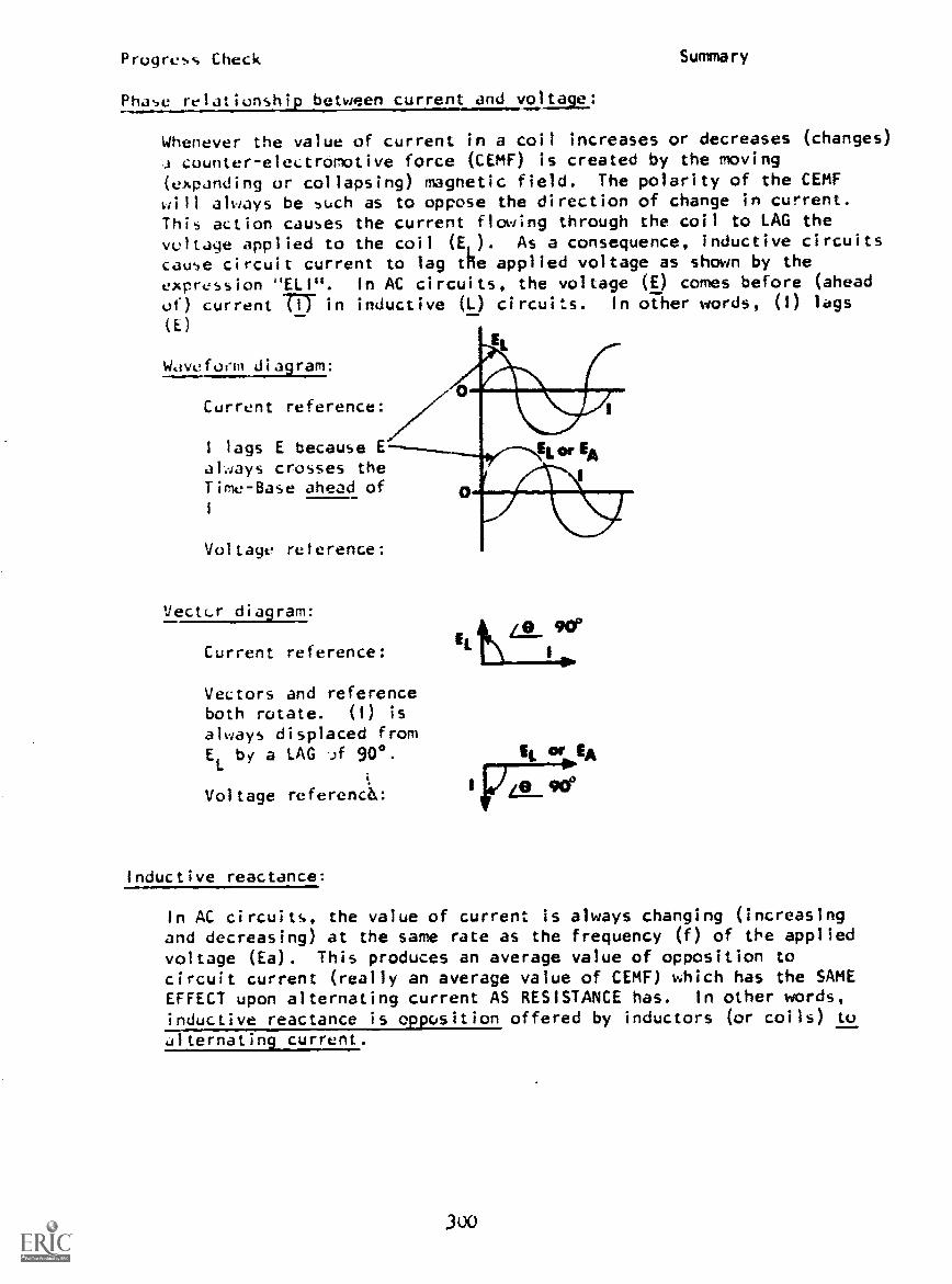
Prugress Check Summary
Phase relationship between current and voltage:
Whenever the value of current in a coil increases or decreases (changes)
counter-electromotive force (CEMF) is created by the moving
(expanding or collapsing) magnetic field. The polarity of the CEMFwill always be such as to oppose the direction of change in current.This action causes the current flowing through the coil to LAG thevintage applied to the coil (El). As a consequence, inductive circuitscause circuit current to lag the applied voltage as shown by the
expression "ELI". In AC circuits, the voltage (E) comes before (ahead
of) current TIT in inductive (L) circuits. In other words, (1) lags
(E)
Waveform diagram:
Current reference:
I lags E because Eal.rays crosses theTime-Base ahead of1
Voltage reference:
Vectc.r dia9ram:
Current reference:
Vectors and referenceboth rotate. (I) is
always displaced fromEL
by a LAG if 900.
Voltage referencd:
Inductive reactance:
It SEA
I IVA_ 90°
In AC circuits, the value of current is always changing (increasingand decreasing) at the same rate as the frequency (f) of the applied
voltage (Ea). This produces an average value of opposition tocircuit current (really an average value of CEMF) which has the SAMEEFFECT upon alternating current AS RESISTANCE has In other words,inductive reactance is opposition offered by inductors (or coils) toalternating current.

Progress Check Stu
Symbol:
"X," ("X" represents reactance and "sub-L" represents selfinductance.)
Basic unit of measure:
ohm Symbol:
Factors which affect the ohmic value of XL:
Frequency (f) of the applied voltage and inductance (L).
Expression:
X = 2-fL (The ohmic value of XL
follows in the same directionoY change as (f) or (1).)
Purpose of inductors:
Because inductors are "frequency sensitive" they are used infiltering circuits, phase-shifting circuits and special wave-form shaping circuits.
POWER:
A term used to describe electrical energy in the process of beingconverted and "supplied" by voltage sources, and being converted and"used" by electrical loads... a complete system of energy conversion.Voltage sources convert other forms of energy to electrical energyand electrical loads convert electrical energy to other forms ofenergy, or store electrical energy in magnetic or electrical fields.
In keeping with the Law of Conservation of Energy, Pout'
the power
"used" by eielctrical loads must always be equal to P. , the powerIn
"supplied" by voltage sources. Electrical loads "tell" the sourcehow much they need by the value of circuit current, in accordance
Eawith the relationships IT =
As a consequence, circuit current (I) is the common factor betweenP.tn
and Pout
.
True Power:
(Abbreviated T.P.) is considered to be P "True" power describeselectrical energy being converted to othP forms of energy: heat
301

Progress Check Summary
and/or light. Resistance is the only circuit component which
"uses" "true" power.
Basic; unit of measure:
Watt (abbreviated W. or w)
Expression:
T.P. = 1
2R (Watts = a.
2x -)
In "purely" resistive DC and AC circuits, with arrx load connection
arrangement, total (true) power (PT) is always equal to the sum
of the individual powers.
Expression:
= P1
+ P2
+ PnPTotal
Reactive Power:
(Abbreviated R.P.) is also considered to be Pout
. However, reactive
power is electrical energy that is cc.iverted to another form of
electrical energy. (Magnetic or electrical fields) when current flows
in circuits which contain inductance and capacitance. In AC circuits
(only) reactive power is stored in magnetic or electric fields and,at some later time, this electrical energy is returned to the source!
Basic unit of measure: (Volt-amperes Reactive) (VAR)
Expression: R.P. - 1
2XL
(or 1
2Xc
) (VAR = a.2
x (reactive))
Apparent Power:
(Abbreviated A.P.) Apparent Power Is always considered to be Pin.
Apparent Power describes the power DC and AC voltage sourcesmust supply to the total electrical load.
Basic unit of measure: VA (Volt-amperes)
Expression: A.P. EalT (VA = Volts x amperes)
In summary, P.In
= EaIT and Pout
= I2RT (for resistive circuits only) or
out= I
22 (for resistive-reactive AC circuits only). Since P.
ry
= Pout
,
then EalT
= I2RT (or I
2Z). Notice that circuit current (1) Is common ...
it appears on both sides of the equal sign.
302
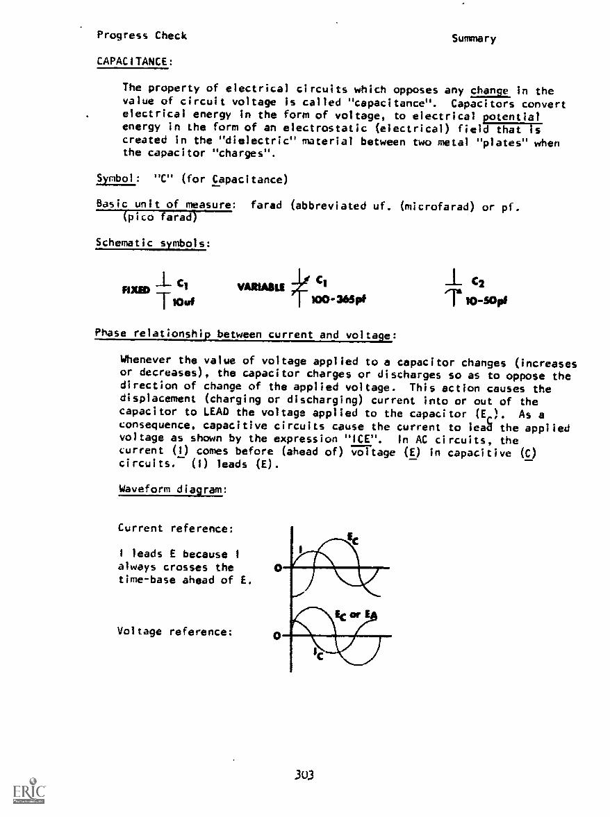
Progress Check Summary
CAPACITANCE:
The property of electrical circuits which opposes any change in thevalue of circuit voltage is called "capacitance". Capacitors convertelectrical energy in the form of voltage, to electrical potentialenergy in the form of an electrostatic (electrical) field that iscreated in the "dielectric" material between two metal "plates" whenthe capacitor "charges".
Symbol: "C" (for Capacitance)
Basic unit of measure: farad (abbreviated uf. (microfarad) or pf.(pico farad)
Schematic symbols:
I C1FIXED
TMut
VARU1SIECI C2
100-3650 111 10-50p.
Phase relationship lJrrentwici tage:
Whenever the value of voltage applied to a capacitor changes (increasesor decreases), the capacitor charges or discharges so as to oppose thedirection of change of the applied voltage. This action causes thedisplacement (charging or discharging) current into or out of thecapacitor to LEAD the voltage applied to the capacitor (Er). As aconsequence, capacitive circuits cause the current to lead the appliedvoltage as shown by the expression "ICE". In AC circuits, thecurrent (1) comes before (ahead of) voltage (E) in capacitive (C)circuits. (I) leads (E).
Waveform diagram:
Current reference:
I leads E because I
always crosses thetime-base ahead of E.
Voltage reference:
303

Progress Check Summary
Vector diagram:
Current reference:
Vectors and referenceboth rotate. (I) is
always displaced fromE by a LEAD of 90 °.
Voltage reference:
Capacitive reactance:
In AC circuits, the value of applied voltage is changing at thesame rate as the frequency of the applied voltage. This produces
an average value of opposition to circuit current (sometimesreferred to as "counter-voltage" because the polarity is alwaysopposing the polarity of the applied voltage). This oppositionhas the same effect upon alternating current as resistance has!In other words, capacitive reactance is apposition offered bycapacitors to alternating current.
Symbol: "Xc" ("X" represents reactance and "sub-C" represents capacitance.)
basic unit of measure: ohm Symbol:
Factors which affect the ohmic value of X : Frequency (f) of the applied
voltage and Capacitance (O.
Expression:
1
XC2:77
(The ohmic value of Xc is always in the opposite direction
of change of (f) or (C).)
Purpose of capacitors:
Because capacitors are "frequency sensitive". They are used infiltering circuits, phase-shifting circuits and special wave-form
shaping circuits.

Progress Check
IMPEDANCE:
Summary
The total opposition to alternating current in any AC circuit Iscalled impedance.
Symbol : "Z"
Basic unit of measure: ohm Symbol: 1.
The impedance (Z) of alternating current circuits is composed ofresistance (R) and/or reactance (X).
Express ion:
RL Circuits: Zv777
RC Circuits: Z = 1)1 +( -X CZ)
Indicates Ea lags 1
T
Waveform and Vector Reiationshies)
AC circuit voltages (ER), (EL), (EC) and (Ea) are vector quantities.
AC circuit oppositions (R), (XL), (Xc) and (2) are also vector quantities.
RL Circuit: (R = XL
Waveform diagram:
Vector diagram:E
RC Circuit: (R = X
Waveform diagram:
Vector diagram:I PIM

-Progress Check Summary
RELATIONSHIP BETWEEN I Ea and Z.
Ohm's Law:
The (value of) total circuit current (IT
) is directly propor-tional to the (value of) applied voltage (Ea) and inverselyproportional to the (ohmic value of) total circuit opposition(Z).
Ea
Expression: IT = rRelationship:
Whenever the value of IT changes, the direction of the change willalways be such as to follow the direction of change in the value ofapplied voltage (Ea) or, in the opposite direction of change in thevalue of im edance (Z). However, you must understand that thedirection of change in the ohmic value of (Z) is ALWAYS determinedby the direction of change in the value of resistance (R), in ohms,the value of inductance (L), in henries, the value of capacitance(C), in farads, or the frequency (f), in Hertz, of the appliedvoltage.
HOW TO USE THE EXPRESSIONS FOR (XL), (Xc), AND (2), WITH OHM'S LAW, TO
ANALYZE AC SERIES RL OR RC CIRCUITS WHEN (f), (L), (C) OR (R) IS INCREASEDOR DECREASED:
RL CIRCUITS:
Circuit diagram:
RL Series Circuit Relationships:
Current: IT =/1.1 /RI M3
V-------71Voltage drops: ET = ERI
1+ ELI
Note: Ea = ET
= E. ELI = Ml
ERI
= Eout
= M2
Impedance: Z = 'R12 + X L12
Sob
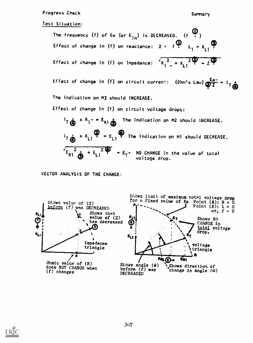
Progress Check Summary
Test Situation:
The frequency (f) of Ea (or Ein) is DECREASED. (f (!))
Effect of change in (f) on reactance: 2 7 fq) L1
XLl
cpEffect of change in (f) on impedance: R12.0 + XL1 =
Effect of change in (f) on circuit current: (Ohm's Law)97 =T
The indication on M3 should INCREASE.
Effect of change in (f) on circuit voltage drops:
11.6 x RIP ER IThe indication on M2 should INCREASE.
I
TxX
Ll4P= E
LIThe indication on Ml should DECREASE.
vERI2
+ ELI
241NO CHANGE in the value of totalvoltage drop.
VECTOR ANALYSIS OF THE CHANGE:
XL,
Shows value of (Z)Wore (f) was DECREASED
Shows that10% value of (2)
has decreased
impedancetriangle
Ohmic value of (R)does NOT CHANGE when(f) changes
Shows limit of maximum total voltage dropfor a fixed value of Ea Point (A): R = 0
Point (11): L = 0or, f = 0
Shows NOCHANGE intotal voltagedrop.
A-
ELI
IP!
ELI
"lb
%ET%
1 %
%16 ET
voltage14 triangle
EAR p ERIShows angle (0) %Shows direction ofbefore (f) was change in angle (0)DECREASED
307

Progress Check Summary
fILTER CHARACTERISTICS STUDY GUIDE
1. Purpose:
The purpose of any filter circuit is to "pass" a desired range or"band" of frequencies and eliminate (reject or discriminate against)
all other frequencies.
The term "pass" means that the amplitude of the output voltage forall frequencies "passed" by the filter ,ircuit will have highenough amplitudes to be used, or is useable, by other circuits.
The term "eliminate" or "discriminate" means that the amplitudeof the output voltage for all frequencies eliminated or discrimin-ated against by the filter circuit will not have high enoughamplitudes to be used by other circuits.
2. Types of filter circuits:
Low-pass - Output voltage amplitude of all "low" frequencies, belowthe cut-off frequency (1
CO), is useable.
Discriminates against "high" frequencies (all frequencies above ).co
High-pass - Opposite of the low-pass filter. Output voltage amplitudeof all "high" frequencies, above the cut-off frequency (f
Li/), is
useable.
Discriminates against "low" frequencies (all frequencies below (I )
cc)
Band-pass - Output voltage amplitude cf all frequencies within agiven range or "band" of frequencies is useable. Hence, the term
"band-pass".
Discriminates against all frequencies above the upper cut-offfrequency. and below the lower cut-off frequency.
Band-Eliminator - Opposite of the band-pass filter. Output voltageamplitude of all frequencies within a given "band" is not useable ...discrimates against these frequencies.
All frequencies above the upper cut-off frequency, and below thelower cut-off frequency have useable output voltage amplitudes.
Also called "band-reject" filter, "band-stop" filter or "wavetrap".
nd Cut-off frequency (L ); The cut-off frecoency uf a filter circuit
is the frequency of iRe applied voltage at which the amplitude ofthe output voltage (Eout) is equal to the 0.707 (70.74) of the applied
(input) voltage (Ein). (Foul = 0.101 x E. n) (When the output voltage
(at any frequency IS greater that 70./ of the input voltage, theamplitude is considered to be "useable".)

0.7W
Progress Check Summary
NOTE: The frequency at which the above condition occurs in lowpass or high pass filter circuits is determined by the value ofR and L for RL circuits, R and C for RC circuits, and the valueof L and C for LC filter circuits.
The upper and lower cut-off frequency of any RLC band-pass orband-eliminator filter circuit is determined by the value of(L), (C) and "Q" of the circuit.
Filter response curves: Output voltage (Eout) vs. frequency (f).
Low-Pass High-Pass
RL, RC or LC Circuit RL, RC or LC Circuit
. aiON
frquancy
309
MoMlid..MOMIRM.M.IM.Maimyymim
frequency
passed

Progress Check
Band-Pass RLC Circuit
Summary
Band-Eliminator RIC Circuit
5. LI filter circuit, low-pass, high-pass, band-pass or band -eliminator can be simplified and analyzed using a basic circuitarrangment that you learned to analyze in Module 5: a seriescircuit with two resistors, one of which is variable.
The analysis of either circuit follows the same pattern:
DC Circuit. Let's assume the ohmic value of R2 is increased (byturning its control knob). This change should cause the value oftotal circuit opposition to current (PT) to increase. The directionof change in RT causes the total circuit current (IT) to decrease(indication on M3 should decrease). The direction of change in IT
310

Progress Check Summary
causes the voltage drop across RI to decrease (indication on MIshould decrease) and the voltcje drop across R2 should increase (asshould the indication on M2), because the total voltage drop acrossRI and R2 (ET) must be equal to the value of Ea.
Filter Circuit. Let's assume that the frequency (f) of the appliedvoltage (E ) is increased, and that the increase in (f) causes thevariable opposition to current in the box marked "frequency sensitive"section, to increase. This direction of change causes the value oftotal circuit opposition (2) to increase. The direction of changein Z causes total circuit current (IT) to decrease (indication on M3should decrease). The direction of change in IT causes the voltagedrop across Ri to decrease (indication on MI shoula decrease) andthe voltage drop across the "frequency sensitive" section increases(as should the indication on M2) because (ET), the vector sum of thevoltage drop across R1 and the "frequency sensitive" section, must beequal to the value of E (Note: Changing the frequency of thevoltage applied to a fi ?ter circuit is NOT the same thing as changingthe value of the applied voltage. The frequency of E is stated inHertz, whereas the value of E is stated in volts. Wen analyzingAC circuits in which the frequa ency of E is increased (or decreased),you must assume that the value of Ea (IR volts) has not changed.)
Conclusion. The "frequency sensitive" section of the filter circuitacts just like the variable resistor in the DC series circuit. Ineither circuit, the value of voltage drop across the variable oppositionto current flow "follows" the direction of change in ohmic value. Inother words, "As an opposition changes, so goes its voltage drop."(This "rule" has two exceptions, both of which are explained onpage 303 of this booklet.)
6. RL Filter Circuits
Circuit Diagram: Voltage drop vs. frequency curves:
311

Progress Check Summary
Analysis of RL filter circuits when the frequency (f) of theapplied voltage (Ea) is increased from a low value to a higher
value.
1. Effect of an increase in (f) on the "frequency sensitive"(reactive) component:
2 f* L- = XL
' (increases)
2. Effect of the change in inductive reactance (XL
) on
circuit impedance (Z):
R2
+ XL
2= 2/ (increases)
3. Effect of the change in (2) on total circuit current (IT):Ea-
= I
T(decreases)
4. Effect of the change in (IT) on the voltage drop across (R)and (L) :
Resistor: IT; x = ER. (decreases)
Inductor: 1T4. x = ELI (increases)*
* The vector sum of ER
and ELwill always be equal to the
value Ea
.
Note: All changes are in the opposite direction when the valueof (f) is decreased (from a high value to a lower value).
For all frequencies of the applied votlage below (f )' the value
of ER
is greater than EL. (The ohmic value of R is greaterco
than
XL
)
When the frequency of Ea is adjusted to fop, ER = EL (point "X");
XL = R, /- = 45' and Eout = 0.707 x Ein (point "X").
For all frequencies of the applied voltage above (f ), thevalue of E
Lis greater than ER. (The ohmic value oPX
Lis
greater than R)
Cut-off frequency: The frequency at which XL = R can be determined
using the expression f =co 27E.
312

Progress Check Summary
5. Effect of a change in the value of (R) or (L) on f :
co
Increased (R)
ko -.new fa)
Increased (L)
6. Possible arrangements for RL filter circuits:
Circuit Diagrams:
HIGH-PASS
LOW-PASS
313
t0.707
t0.707
Response Curves: (E vs. f)out
fragrancy

Progress Check
7. RC Filter Circuits
Circuit Diagram:
0.707
Summary
Voltage drop vs. frequency curves:
frequttney-
Analys;s of RC filter circuits when the frequency (f) of theapplies voltage (Ea) Is increased from a low value to a highervalue.
1. Effect of an increase in (f) on the "frequency sensitive"(tclactive) component:
2: ft C= X
C4 (decreases).-.
2. Effect of the change in capacitive reactance (X c) on circuitimpedance (Z):
4R 2+ (-X 4)
2= 24 (decreases)
3. Effect of the change in (Z) on total circuit currentEa.
4
= 1
Tt (increases)
4 Effect of the change in (IT) on the voltage drop across (R)and (C):
Resistor: 1
Tt x R+ = ER+ (increases)*
Capacitor: ITt x Xc4 = Ec4 (decreases)*
*ThevectorsumofERand E will always be equal to the value of
(Y:
E.
3114

Progress CheckSummary
NOTE: All changes are in the opposite direction when the valueof (f) is decreased (from a high value to a lower value).
For all frequencies of the applied voltage below (f 0), thevalue of E is greater than ER. (The ohmic value o? Xc isgreater th3n R)
When the frequency of Ea is adjusted to fc0, Ec = ER (point "X");
XC = R. /0 = 45° and Eout = 0.707 x E
in(point "X").
For all frequencies of the applied votlage above (f 0), thevalue of ER is greater than Ec (the ohmic vlaue of fi is greaterthan X ).
Cut-off frequency: The frequency at which Xc = R can be
determined using the expression f =co rirre
Effect of a change in the value of (R) or (C) on fco:
Increased (R) Decreased (C)
3)5
frequency

Progress Check Summary
Possible arrangements for RC filter circuits:
Circuit Diagrams:
LOW-PASS
C
R
HIGH-PASS
t
Response Curves: Emst
vs. f
0.707 -1
Passed'2g
t0.707
316
fc o
----frequency
frequency --a.
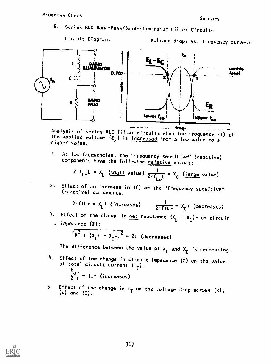
Progrss CheckSummary
8. Series RIC Band-Pass/Eland-Eliminator filter Circuits
Circuit Diagram: Voltage drops vs. frequency curves:
os 1 uPPer fco
Analysis of series RIC filter circuits when the frequency (f) ofthe applied voltage (Ea) is increased from a low value to ahigher value.
1. At low frequencies, the "frequency sensitive" (reactive)components have the following relative values:
2-fLoL = XL (small value) -------- X (large value)2fif
Lo2. Effect of an increase in (f) on the "frequency sensitive"
(reactive) components:
1= XLt (increases)271fiC0
= XC
4 (decreases)
3. Effect of the change in net reactance (XL - Xc)* on circuitimpedance (2):
R 2+ (XLt y) 2
= (decreases)
The difference between the value of XL
and X is decreasing.
4. Effect of the change in circuit impedance (z) on the valueof total circuit current (IT):
E
Z. = IT? (increases)
5. Effect of the change in IT on the voltage drop across (R),(L) and (C):
317

Progress Check Summary
Resistor: I
Tx = E
Rt (increases)"
inductor: 1Tt x XL = EL
t (increases)
Capacitor: ITT x = Ec4 (decreases)**
Inductor and Capacitor: (E0 - Ec4) 4(decreases)*
** The vector sum of ER and the value of (EL - EC) will always
be equal to the value of Ea.
When the frequency of E is increased to the lower cut-off
frequency, ER = (EL - Ec), point "X" on the voltage curves.
NOTE: For all frequencies of E , below (f ), the.ohmic value
X I.; greater than Xi; consequefltly, the value of Er is
greater than EL so the circuit appears capacitive to the
source: IT leads E . To see the equivalent.series circuit,
cover the inductor IL) of the circuit diagram.
Circuit diagram: Voltage vs. frequency curves:
i:4) max. ER
t i Iv Ec ,.
RAND usableELIMINATOR I
1 hnolht.. .O /MO
lower fa)
win IrkER
upper fco
freq.
Analysis of series RLC filter circuits when the frequency (f) of
the applied voltage (E ) is increased from the lower f to f
(f0) designates the ""resonant""""resonant"" frequency of an RLC cirE0 uit. o
(f,,) is the frequency of the applied voltage which causes the
value of X to have the same ohmic value as X X. Note: Any
frequency bf E , can be a "resonant" frequency, it all depends
on the value off' (L) and (C) In an RLC circuit.
When the frequency (f) of the applied voltage is adjusted to the
frequency which causes "resonance" the following circuit conditions
exist:
318

Progress CheckSummary
1. Net circuit reactance: X has decreased and XL
has increaseduntil, at f
o'XL. X
C consequently, the difference between'
these two values (XL
- XC
) is zero (or minimum).
2. Effect of minimum value of net circuit reactance on circuitimpedance (Z):
.rR2+ (X
LXC)
2 R2+ (0) m Z (At f
o, 2 R)
The value of (Z) is minimum.
3. Effect of minimum circuit impedance (Z) on the value of totalcircuit current (I ):
E
if-7 I: 1T (maximum)
min
4. Effect of maximum value of IT on voltage drop across (R),(L) and (C):
resistor: 1
T(max) x R ER (maximum)
inductor: I
T(max) x XL . EL (very large value)
capacitor: 1T(max) x Xc = Ec (very large value)
EL
E
Inductor and Capacitor: (EL - Ec) = 0 (minimum)
Circuit Diagram: Voltage drop vs. frequency curves:
319
freq.

Progress Check Summary
Analysis of series RLC filter circuits when the frequency (f) of
the applied voltage (Ea) is increased from fo to the upper fc0.
1. When the frequency of E is the resonant frequency, the
following circuit conditions exist:
XL= X
C'therefore (X
L- X
C) = 0. Z is minimum (equal to R)
EL = EC; therefore, (EL EC) = 0. ER
is maximum (equal to Ea)
Since the value of (Z) is minimum, IT is maximum.
2. Effect of a further increase in (f) on the "frequency sensitive"
(reactive) components:
2-ftL = XL
t (increases) 3747. s Xc4 (decreases)
3. Effect of the change in net reactance (XL - X ) on circuit
impedance (Z):
'R2+ (X
Lt - X 4)
2= Z1 (increases)
The difference between the value of X and X is now increasing,
because the value of XL is greater thin X.
4. Effect of the change in circuit impedance (Z) on the value of
total circuit current (IT):
a-y7 . 11.4 (decreases)
5. Effect of the change in IT on the voltage drop across (R),
and (C):
Resistor:T
x 11-1. = ERf (decreases)
Inductor: x XLt = ELt (increases)
Capacitor: IT. x Xc. = EC: (decreases)
Inductor and Capacitor: (ELt Ec4) 4(increases)
When the frequency of E is increased to the upper cut-off frequency,
ER= (E
LEC
) point AP" on the voltage curves. Note: For all
frequencies of Ea'
above (f ), the ohmic value of XL
is greater than
Xc; consequently, the value of EL is greater than EC, so the circuit
appears inductive to the source: IT au. Ea. To see the equivalent
series circuit, cover the capacitor (C) of the circuit diagram.
320

Progress CheckSummary
Resonant frequency (f ):
When the frequency (f) of Ea is such that the ohmic value of XLis equal to Xc, for any RIC circuit, that frequency is called
the "resonant" frequency. The value of (f ) for any RLC circuitis determined only by the values of (L) an (4) in the circuit.
fo
= or f = .1522n1/07. o Aor
Effect of changing the value of (1.) or (C) on the value of (f0):
Decreased (I)
_ frequency-4..
Increased (C)
MOW AD 14 _.Jfo
frequency
Possible arrangements for series RLC filter circuits:
Circuit Diagrams:
.-y-y-e-H
i\vEt.
321
Response Curves:(Eout vs. f)

Progress Check Summary
Pubibie arrangements for series RLC filter circuits (can't):
Circuit Diagrams: Response Curves: (EOut
vs. f)
Summary of Series RLC Circuit Conditions:
322

Progress CheekSummary
Circuit conditions below resonance:
I. The ohmic value of Xc is larger than XL.
2. Z is a large value (due to large value of Xc).
3. I
Tis a small value (due to large value of Z).
4. Ec is larger than EL.
5. EC) is large (due to large value of Er). ER is small.
6. The circuit appears capacitive to the source: I
Tleads E.
C' -cult conditions at resonance:
The ohmic value of X it equal to XL.
2. Z is minimum (equal f.o the ohmic value or R.) X ) = 0
IT is maximum (due to the minimum value of 2)
4. EL
is equal to E (very large voltages).
5. ER
is maximum. (EL
EC) is minimum.
6. The circuit appears resistive to the source: 1
Tin phase
with Ea
.
Circuit conditions above resonance:
1. The ohmic value of XL is larger than X.
2. Z is a large value (due to large value of XL).
3. I
T is a small value (due to large value of 2).
4. EL is larger than Ec.
5. (EL
EC
) is large =LA.- to large value of EL). E
Ris small.
6. The c'i..uit appear inductive to the source: I
TLags E.
323
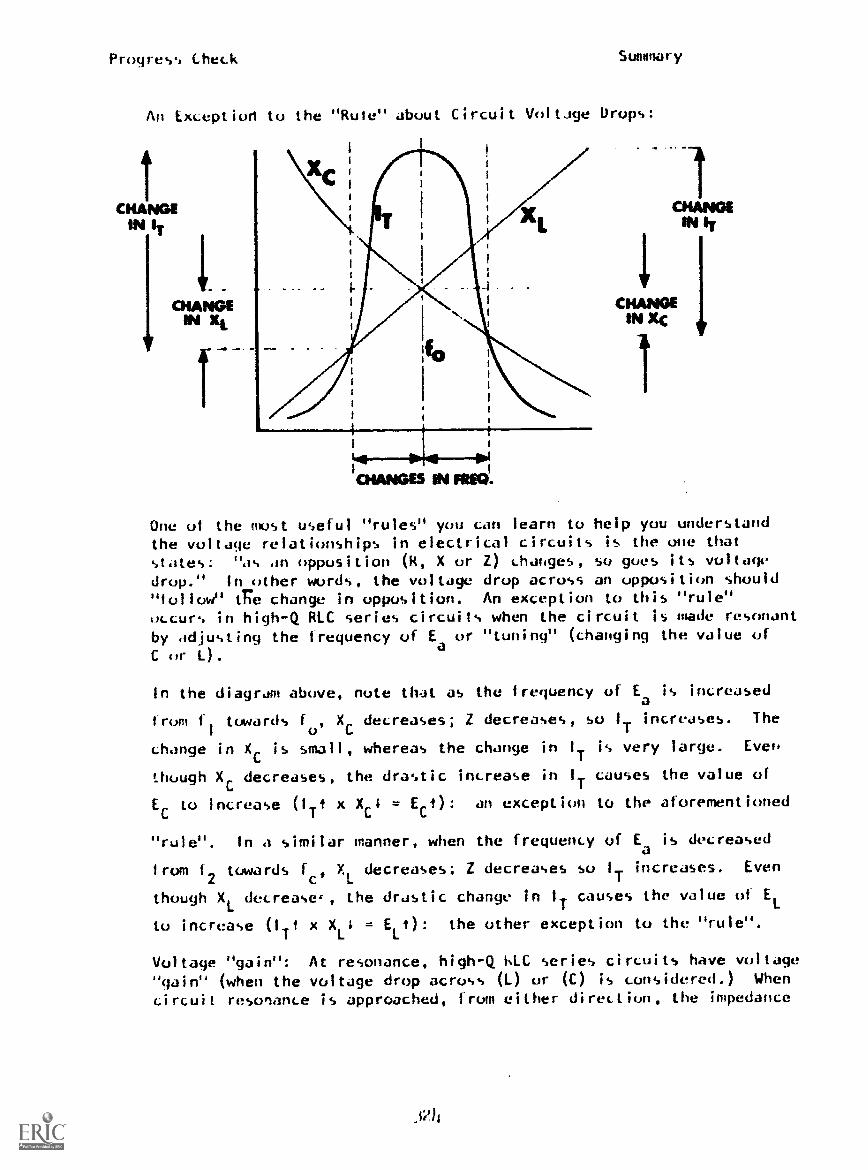
Proyre.,., Check Summary
An Exception to the "Rule" about Circuit Vol tJge Drops:
CHANGEIN IT
1CHANGES MM *EL
One of the oust useful "rules" you can learn to help you understandthe voltage relationships in electrical circuits is the one that
states: "as an opposition (R, X or Z) changes, so goes its voltagedrop." In other words, the voltage drop across an opposition should"follow" egie change in opposition. An exception to this "rule"occur% in high-Q RLC series circuits when the circuit is made resonant
by adjusting the frequency of Eaor "tuning" (changing the value of
C or 1.).
In the diagram above, note that as the frequency of Ea is increased
from f
1
towards fo'
XC
decreases; Z decreases, so I
Tincreases. The
change in Xc is small, whereas the change in IT is very large. Even
though Xc decreases, the drastic increase in IT causes the value of
E to increase (IT? x X 4 = E 4): an exception to the aforementioned
"rule". In a similar manner, when the frequency of Ea
is decreased
from f2
towards fc , XL decreases; Z decreases so I
Tincreases. Even
though XL. decrease', the drastic change in IT causes the value of EL
to increase (Iit
x XL4 = EL 1): the other exception to the "rule".
Voltage "gain": At resonance, high-Q 6LC series circuits have voltage"gain" (when the voltage drop across (L) or (C) is considered.) When
circuit resonance is approached, from either direction, the impedance
_Ph

Pr dress Check Summary
(Z) of the circuit decreases sharply with a corresponding drasticincrease in total circuit current (I ). The large current causes
Ithe individual voltage drops across L) and (C) to increase to veryhigh voltages at resonance. (in some circuits, it is possible forthe value of E
L(and EC) to be many times the value of E
a!) The
large increase in value of EL (and EC '
) at resonance, is called
voltage "gain".
Note: Voltage "gain" is very useful in series RLC band-pass filtercircuits, particularly when the coil (L) is the primary of atransformer. Also, the voltage and current rating of the partsused in high-Q RLC band-pass and band-eliminator filter circuitsmust be capable of handling the large current and high voltageswhich can occur when a circuit is caused to be resonant.
"Q": The "Q" (for Quality) of a coil is a number that representsthe ratio of energy stored (in the magnetic field of the coil) toenergy used (converted to heat) by the "effective resistance" ofthe coil. There are two kinds of "Q": and
Qcoil0-ckt'
Qcoil The value of Qcoil is determined by the following relationship:
/XL
XL 2rftL,
Reff
= Q coil Reff
Reff
t Qcoil)
(Refer to the example in the parentheses above.) Within the limitsof the frequency range for which it is designed, the value of
Qcoilshould not change with changes in frequency of E This is becausethe ohmic value of R
eff (due to "skin effect" an "proximity effect")
changes in the same direction as the value of XL when the frequencyof E
ais changed. '
Qckt
: The value of Qckt is determined by the following relationship:
XL
XL 21Tf4i.-4.
RT Qckt RT= Q
ckti
In the case of 0ckt' the total resistance of the circuit includes the
ohmic value of Reff
of the coil. The value of Qckt should always be
smallerthanQcoirAswithQcoil,the value of XL follows the direction
of change in frequency of Ea; however, unlikeQcoil'
the effect of any
change in value of Reff
(normally a small ohmic value) is "swamped"
(reduced) by other resistances in the circuit. (The value of totalcircuit current is also less.) The "swamping" effect of other circuitresistances causes the value of Q
ckt to change when the frequency of
Ea
is changed. As a consequence. the lower value of Qckt
is used as
the figure to determine the bandwidth of RLC bandpass and band-eliminator
325

Progress Check Summary
titter circuits.
Bandwidth: This term is used to describe the number of frequencies
contained within the "band" between the upper and lower cut-off
frequency occurs is determined by Qckt
in accordance with the
following relationship:f
= Bandwidth (B.W.)Qckt
(Note: Use of this relationship assumes that f0, the frequency of
Ea
which causes the filter circuit to become resonant, is the
center frequency within the bandwidth.)
Bandwidth may also be determined by subtracting the lower cut-off
frequency (f1) from the upper cut-off frequency (f2) as follows:
(upper fGQ - lower fa) = (f2 - fl) = Bandwidth (6.14.)
Low-Q circuits (Q's less than 10) have wide bandwidths. (Many
frequencies between f1
and f2), and high-Q circuits have narrow
bandwidths (fewer frequencies between f1
and f2).) The higher
the value of Qckt'
the narrower the bandwidth of the circuit.
The illustrations show how the bandwidth of RLC filter circuits
is affected by the value of 0-ckt'
9. Effect of Value of "Q" on Bandwidth of Filter Circuits:
fof
HIGH Q
0.707LON Q
ikhz
I 1
920
------ Radio Station Frequencies in KHz
326

Progress Check Summary
To see how the value of 0ckt
affects the output voltage vs.
frequency response of band-pass filter circuits, let's assumethat you live in a town which has three radio stations that areclose together, as far as their broadcasting frequencies areconcerned. You want to listen to the station which broadcastson a frequency of 890 KHz., but the filter circuits in yourradio have a low value of "Q". Now, refer to the low-Q band-pass filter response curve on the diagram. It has a widebandwidth. As a consequence, there is a useable output voltage3171177Tariat the frequency of each radio station .... they areall being "passed". With this kind of response, when you tunedthe radio to 890 KHz., you would hear all three radio stationsat the same time! Now look at the curve for the high-Q band-passfilter circuit. It has a narrow bandwidth. When the filtercircuits in a radio have 67 717nd of response, only the frequencyof 890 KHz (9KHz on either sid.1 of 890 KHz) will have a useableoutput voltage and be "passed". By comparing the two responsecurves, you should be able to see that the frequencies of theother two radio stations are effectively filtered out by thenarrow bandwidth of the high-Q filter circuit.
Note: The ability of filter circuits to discriminate betweenfrequencies that are close together is called "selectivity".(Low-Q circuits are hot as frequency selective as high-Q circuits.)-
The diagram below shows how the value of 0ckt
affects the bandwidth
(and the selectivity) of band-eliminator filter circuits.
.66
LOW Q% 1% 1 //HIGH Q
I 1 ,
1
t
1 .t.t,;
\14 !
1
860 --r-8 Q 920
Radio Station Frequencies in KHz lift
10. "Tuning" of RLC Band-Pass Filter Circuits:
"Tuning" is the process of changing the value of (1) or (C) ofan RLC filter circuit so it will be resonant to a differentfrequency of .molied voltage. (The most common method is to
327

Progress Check Summary
change the value of (C), using a variable capacitor.) The following
diagrams illustrate what happens to (fu) and bandwidth of a band-pass
filter circuit when the value of (C) is changed.
In Figure 1, the LC product of the circuit makes it resonant toan applied voltage with a frequency of 890I(Hz. When the circuit
is "tuned", by increasing the value of (C), the circuit iscaused to be resonant to a lower value of (f ). Notice that the
bandpass curve shifts and centers itself over the new value of
(1o).
Figure 1.
560Khz
frimeency
890Khz
In Figure 2, the clicuit is tuned to a higher value of (f0) by
decreasing the value of (C). In this case the band-pass curveshifts and centers itself over the new, higher value of (f0).
1
= f
27*L,C4.0
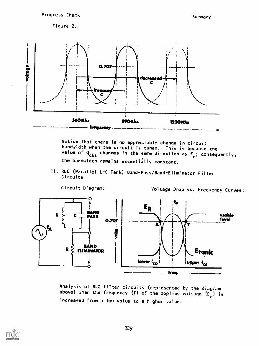
Progress Check
Figure 2.
Summary
560Khz 890KhzfrequencY
r2201131:
Notice that there is no appreciable change in circuitbandwidth when the circuit Is tuned. This is because thevalue of Q
ckt changes in the same direction as f0; consequently,
the bandwidth remains essentially constant.
II. RLC (Parallel L-C Tank) Band-Pass/Band-Eliminator FilterCircuits
Circuit Diagram:
0.707
i
Voltage Drop vs. Frequency Curves:
Analysis of RLC filter circuits (represented by the diagramabove) when the frequency (f) of the applied voltage (Ee) is
increased from a low value to a higher value.
329
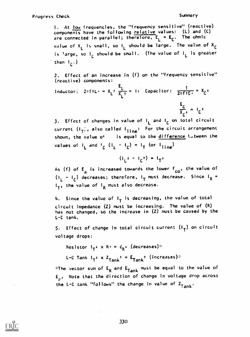
Progress Check Summary
1. At low frequencies, the "frequency sensitive" (reactive)
components have the following relative values: (L) and (C)
are connected in parallel; therefore, EL = EC. The ohmic
value of XL
is small, so I
Lshould be large. The value of X
is large, so lc should be small. (The value of I
Lis greater
than IC.)
2. Effect of an increase in (f) on the "frequency sensitive"(reactive) components:
E1
Inductor: 2rftL. = X --= 14 Capacitor: X 4L XLt 2rftC. C
EC
Ick
3. Effect of changes in value of 1
Land 1 on total circuit
current (IT" also called Cline: For the circuit arrangement
shown, the value o4 is equal to the difference Ltween the
values of IL and 'c (IL 1c) = IT (or Mine)
(1L
4 - 1 t) = 1
T4
As (f) of Ea
is increased towards the lower fco
, the value of
(IL
IC) decreases; therefore, I
Tmust decrease. Since 1
R=
I
T'the value of I
Rmust also decrease.
4. Since the value of I
Tis decreasing, the value of total
circuit impedance (2) must be increasing. The value of (R)has not changed, so the increase in (2) must be caused by the
L-C tank.
5. Effect of change in total circuit current (IT) on circuit
voltage drops:
Resistor I
T4 x R = ER4 (decreases)*
L-C Tank IT4 x ZTank
= ETank
i (increases);
The vector sum of ERand E
Tankmust be equal to the value of
E,. Note that the direction of change in voltage drop across
the L-C tank "follows" the change In value of ZTank.
330

Progress Check Slifrifllary
When the frequency of Ea is increased to the lower cut-off
frequency, ERETank' (Point "X" on the voltage curves.)
Note: For all frequencies of Ea
, below fo
, the value of XL
is less than Xc; therefore, the value of IL is greater than lc.
The circuit appears inductive to the source. IT lags Ea. To
see the equivalent series circuit, cover the capacitor (C) ofthe circuit diagram.
Circuit Diagram: Voltage Drop vs. Frequency Curves:
usablelevel
freq.
Analysis of RLC filter circuits (represented by the diagramabove) when the frequency (f) of the applied voltage (Ea) is
increased from the lower fco
to f0. (f ) designates the
"resonant" frequency 4 the L-C tank. (f ) is the frequency
of the applied voltage which causes the value of XL to have
the same ohmic value as X. Note: la. frequency of Ea
can be
a resonant frequency depending upon the value of (L) and (C)of the L-C tank.
When the frequency (f) of the applied voltage is adjusted tothe frequehcy which causes "resonance" the follow.ng circuitconditions exist:
1. Reactance: XL = Xc (L) and (C) are connected in parallel;
E = EL
E
2. Current: %LC
= = IL =L C
331
circulating

Progre.-s Check Summary
Within the L-C tank, the circulating current (Icirc
) is maximum.
(Limited only by the resistance in the tank.)
(IL
IC) = IT atus
1
L= 1
Cstherefore, the value of (I
LI
C)
= 0.
Total circuit current (IT) is minimum. (Note: The minimum value
of 1
Tdepends on the value of Q
ckt)
3. Impedance: When the tank is made resonant, it offers maximumopposition (2) to circuit current.
Total circuit impedance (2) is maximum.
4. Circuit voltage drops:
Resistor: 1
T(min) x R = ER (minimum)
Inductor: I
(-A.
rc(max) x XL = EL (maximum)
Capacitor: 1 I.rc
(max) x XC = EC (maximum)
L-C Tank: 1
T(min) x
Tank(max) = E
Tank(maximum)
Voltage Drop vs. Frequency Curves:Circuit Diagram:
ammoPASS
COW-
tBAND
ELIMINATOR
332
fro*

Progress Check Summary
Analysis of RLC filter circuits (represented by the diagramwhen the frequency (f) of the applied voltage (Ea) is
increased from fo
to the upper fco
1. When the circuit is resonant, the following conditionsexist: XL = Xc, (L) and (C) are connected in parallel, so
EL = EC. IL = IC which is also the value ofc
1
irc. (z) is
maximum; (IT
) is minimum. ETank is maximum; E
Ris minimum.
2. Effect of an increase in (f) on the "frequency sensitive"(reactive) components:
Inductor: = X tEL
= 11.4 Capacitor: 17771
77.= Xc,
4
CX
.
C
3. Effect of changes in value of 1
Land I on total circuit
current (IT), also called 1
line: For the circuit arrangement
shown, the value of IT is equal to the difference between the
values of I
Land
I. (IL - IC) = I
T(or 1
line)
1Ct) IT1
As (f) of Ea is increased, from fo towards the upper +-co, lc
becomes greater than IL. The value of (IL - IC) increases;
therefore, I
Tmust increase. Since I
R= I
T'the value of I
Rmust also increase.
4. Since the value of 1
T is increasing, the value of total
circuit impedance (2) must be decreasing. The value of (R)has not changed, so the decrease in (2) must be caused by theL-C tank.
5. Effect of change in total circuit current (IT) on circuit
voltage drops:
Resistor: ITr x R. = ER
(increases)*
L-C Tank: 1Tt xTank
i
ETank4'(decreases):
The vector sum of ER and ETank must be equal to the value of E .
Note tnat the direction of change in voltage drop across theL-C tank still "follows" the change in value of ZT,r11,.
333
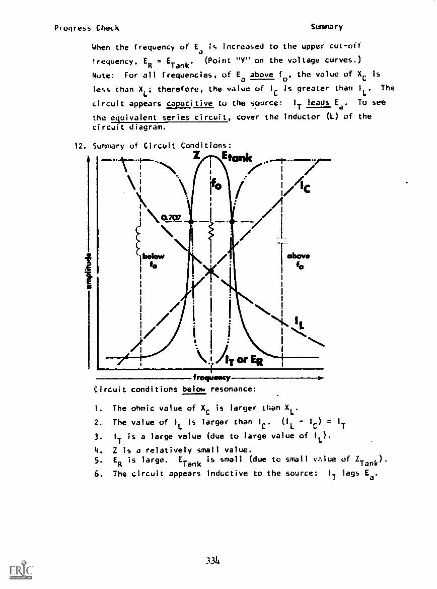
Progress Check
12.
Summary
When the frequency of Ea is increased to the upper cut-off
trequency, ER = ETank
. (Point "Y" on the voltage curves.)
Note: For all frequencies, of Ea
above fo
, the value of Xc is
less than XL; therefore, the value of lc is greater than 1L. The
circuit appears capacitive the source: IT leads Ea. To see
the equivalent series circuit, cover the inductor (L) of the
circuit diagram.
Summary of Circuit Conditions:
/ IC
irNO. 707 /
N\ab&ow
I-ammo
1
1 IL
..\JATor ER
frequolscy
Circuit conditions below resonance:
1. The ohmic value of XC is larger than XL.
2. The value of I
Lis larger than I
C'(I
L1G) =
T
3. 1T is a large value (due to large value of IL).
4. Z is a relatively small value.5. E
Ris large. E
Tankis small (due to small vrnlue of Z
Tank)
6. The circuit appears inductive to the source: IT lags Ea.
334
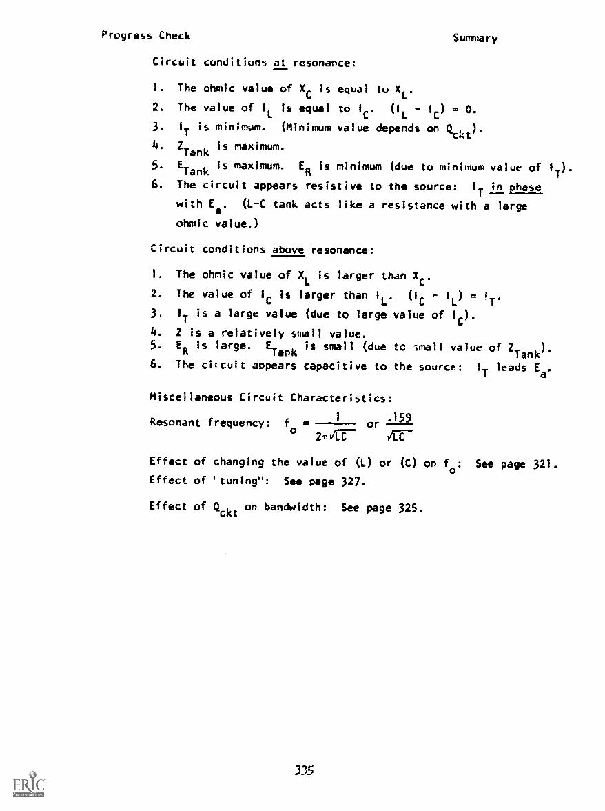
Progress Check Summary
Circuit conditions at resonance:
1. The ohmic value of Xc is equal to XL.
2. The value of IL is equal to lc. (IL - 1c) = O.
3. IT is minimum. (Minimum value depends on Qc4t).
4.ZTank
Is maximum.
. ETank
Is maximum. ER is minimum (due to minimum value of IT).5
6. The circuit appears resistive to the source: IT in phase
with E. (L-C tank acts like a resistance with a large
ohmic value.)
Circuit conditions above resonance:
1. The ohmic value of XL
is larger than XC.
2. The value of lc is larger than IL. (1c - IL) = IT.
3. IT is a large value (due to large value of 1c).
4. Z is a relatively small value.5. ER is large. E-
ank is small (due to small value of ZTank
)l
6. The ciicuit appears capacitive to the source: IT leads Ea.
Miscellaneous Circuit Characteristics:
/ '159Resonant frequency: f = - orc) 27.40r-
Effect of of changing the value of (L.) or (C) on fo: See page 321.
Effect of "tuning": See page 327.
Effect of Qckt on bandwidth: See page 325.

Progress Check Summary
Possiblz arrangements for parallel RLC filter circuits:
Circuit Diagrams:
336
Response Curves:
(Eout
vs. f)

Progress Check Summary
WAVE FORMS, VECTORS AND PHASE RELATIONSHIPS
LEARNING OBJECTIVES:
Recognize the relationship between in-phase and out-of-phase a-cvoltage waveforms and their corresponding diagrams in terms of ampli-tude, phase, magnitude and direction, given statements, writtenproblems, waveform diagrams or vector diagrams.
REFERENCES:
hAVPERS 93400A-1A, Fundamentals of Electronics, pages 156-160.
Application Items:
1. Identify the phase relationship of El with respect to £2 and thephase relationship of the resultant waveform with respect to Elor E2 in terms of leading, lagging, or in-phase for thefollowing:
a. El is
resultant is£2, the b. El is
resultant isEl. E2.
c. El IsresultantEl.
E2, the
E2, the d. El is
337
resultant isE2.
E2, the
RESULTANT
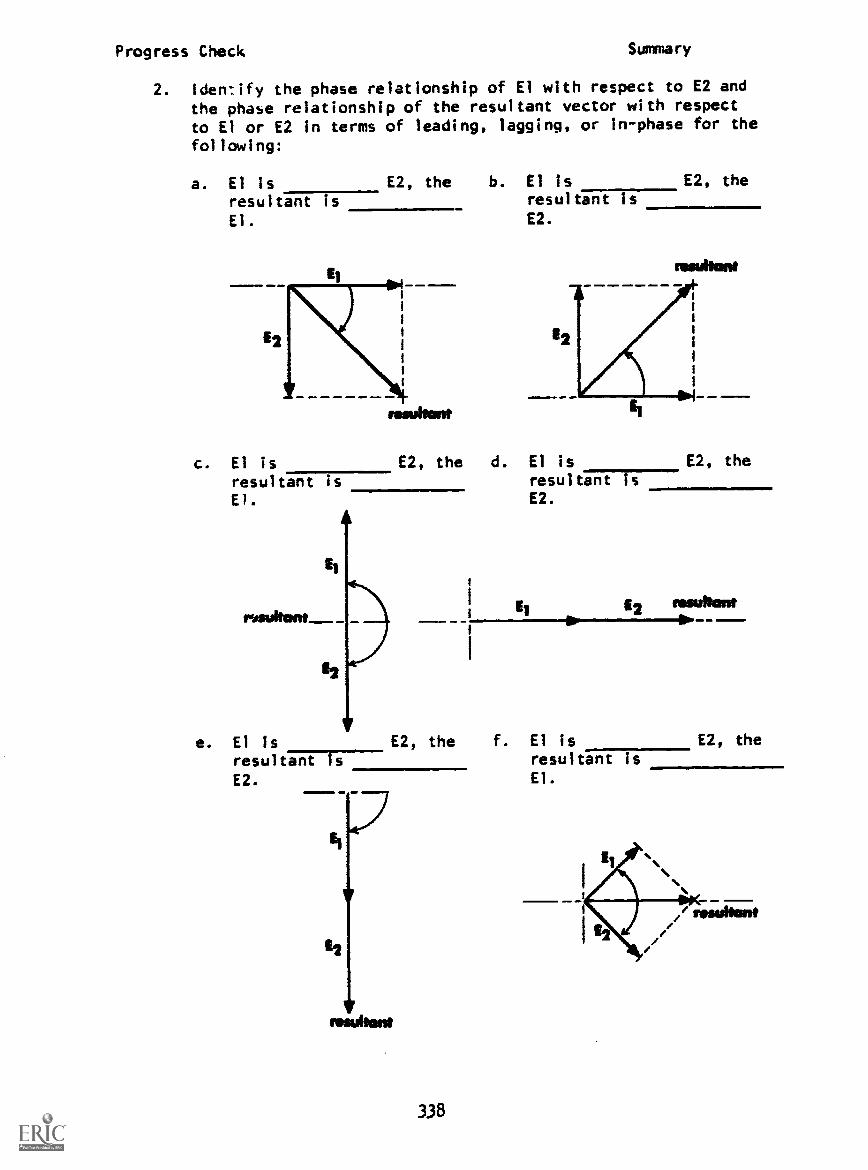
Progress Check Summary
2. Iden :ify the phase relationship of El with respect to E2 andthe phase relationship of the resultant vector with respectto El or E2 in terms of leading, lagging, or in-phase for the
following:
a. El is E2, the b. El is
resultant 7----El.
c. El is
resultant isEl.
resultant is
E2.
E2, the
£2, the d. El is
resultant is£2.
EtOr
E2, the
fesultant
e. El is E2, the f. El is E2, the
resularaTT----£2.
338
resultant isEl.

Progress Check Summary
3. Match the waveform diagrams with their corresponding vectordiagrams. The resultant waveform has been omitted for clarity.
(Hint: Observe the difference in amplitude of the variouswaveforms.)
a. b.
c. d.=11INIIO
A.
D. i
a. I
339
F.

Progress Check Summary
4. Solve the following problems for the quantities indicated:
a. Effective value of the resultantvoltage:
Draw a vector diagram that showsEl, E2 and the resultant vector.
at. ma. ..ms wm. Im m. ..o
1
If the peak value of El was increased by y0 volts, what wouldbe the magnitude of the resultant
b. Effective value of the resultantvoltage?
L42.42vpk
Draw a waveform that shows El, E2and the resultant waveform.
; II1
1 1 I1
1 1
1 1 I
1t 1
I I I
52II
1 I 1
II I
$
T 28.28vpig II I
s
1
I
II I I
1 1 I I
fe 90° 190° 2700 360e
340
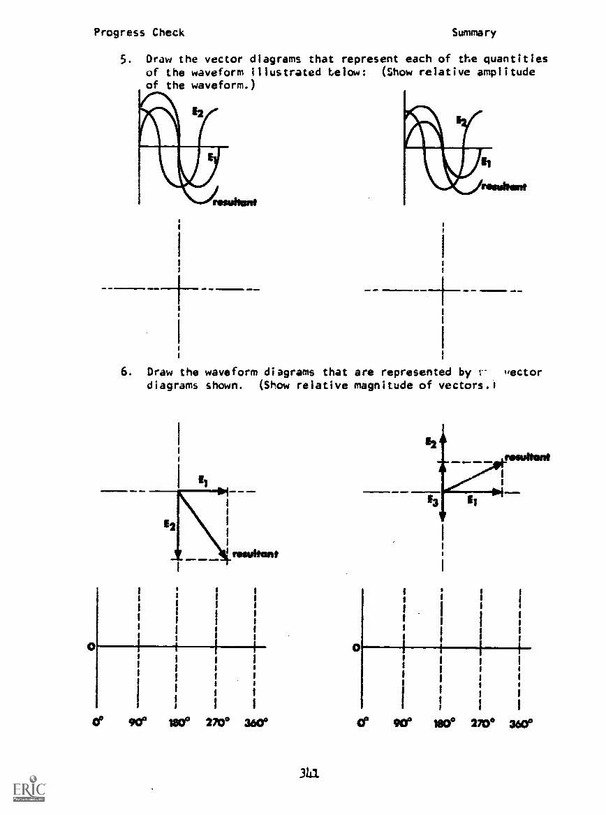
Progress Check Summary
5. Draw the vector diagrams that represent each of the quantitiesof the waveform illustrated below: (Show relative amplitudeof the waveform.)
±.d =o ! .=1. e
6. Draw the waveform diagrams that are represented by I- "ectordiagrams shown. (Show relative magnitude of vectors.)
IMMEIMINN OMIm
I I
I
I
0° 90° WO° 270° 3600
343.
a
13 1
I
I
0° 90° 180° 270° 360°

Progress Check
SERI ES CIRCUITS
Summery
111 illIM MIIIIM 81111 11=1110 Mil, =1111 mMINI=1.11
SIN
COS
TAN =
xY ;R
ER PTAEUI r " 15 TiVIT
AE P
X x x OPP
Wmr1711 /cm A"
OPPz' HYP
312

Progress Check
PARALLEL CIRCUITS
OPP ix PxTli 17 7 T
T A
ADJ IR PT=HYP IT PA
OPPIx Px
ADJIQ
PT
'X
Summary
px
BEST COPY AWIRABIE
33
M.M.1. 40.=..... IIMIMOM 11M1.1. MMINP ...la.=

Progress Check Summary
'..F.R11,KI:ar.AN1 11144111S
..sesve Mae,
I. t ha' 1; .. it .c and t h. A.: %,0 I tt41 sour. If 4' all .1i itN.
gurionaV u Mhn the reactance f Lt. th. tame of C.
I. At %ortv entrnt is a maxi-=um tvtry nighl.
At rt.4onan.... sesies tesunant uircuitacts like a resistor of low ohmic value.
Ai tes..oto.e. the voltages across L and Care .14:al in magnitude by 180 degrees outof phase with each other.
At re,.:1Athe. the -same current flows
thro.;0 the entire circuit.
i. At tsnan.e, the voltage across eitheror C may be greater than that of the
source, giving resonant voltage step-up.
At res onante. inereasing the value ofail resistance R lowers the circuiturrent, thereby lowering the resonantvoltage .tell -up.
9. Oil resonance, .he circuit arts like thatpart which has the higher reactance.a. Increasing C above its at-resonance
value makes the circuit act like acoil.
b. Reducing C below Its at-resonancevalue makes the circuit act like acapacitor.Int.:easing I. above its at-resonancevalue makes the circuit act like atoil.
d. Reducing L below its at-resonancevalue makes the circuit act like acapacttur.
e. Applying a higher frequency than therescant One makes the circuit actlike a coil.
f. Applying a lower frequency than theresonant one makes the circuit actlike .apacitur.
10. The proeuct LC is constant for any givenresonant frequency.
Increasing L or increasing C lowers theresonant frequency.
12. Decreasing L or decreasing C raises theresonant frequency.
13. The V factor of the circuit is essen-tially eqcal to the coil reactance divid-ed by the' AC resistance of the coil.
PARALLEL-RESONANT CIRCUITS--------- _
i. the coil. the capacitor and the ACvoltage source are all in parallel.
Resonance occurs when the reactance ofL is equal to the reactance of C.
3. At resonance, source current is aminimum (very low).
4. At resonance, a parallel resonant circuitacts like a resistor of high ohmic value.
S. At resonance, the voltages across 1., C,and the source e all the same inmagnitude and e.
6. At resonance, .c currents through L andC are essentially equal in magnitude butare 180 degrees out of phase.
7. At resonance, the current through eitherL or C is greater than the source current,giving reconam current step-up.
S. At resonance, increasing the value of coilresistance R increases line current,thereby lowering the resonant currentstep-up.
9. Off resonance, the circuit acts likethat part which has the lower reactance.a. Increasing C above its at- resonance
value maksa the circuit act like acapacitor.
b. Reducing C below its at-resonancevalue makes the circuit act like acoil.
c. increasing L above its at-resonancevalue makes the circuit act like acapacitor.
d. Reducing L below its at- resonancevalue makes the circuit act likecoil.
e. Applying a higher frequency than theresonant one makes the circuit actlike a capacitor.
f. Applying a lower frequency than theresonant ore makes the circuit actlike a coil.
10. The product LC is constant in any givenresonant frequency.
11. Increasing L or increasing C louvre theresonant frequency.
12. Decreasing L or decreasing C raises theresonant frequency.
13. The Q factor of the circuit is essen-tially equal to the coil reactance divid-ed by the AC resistance of the coil.
31414
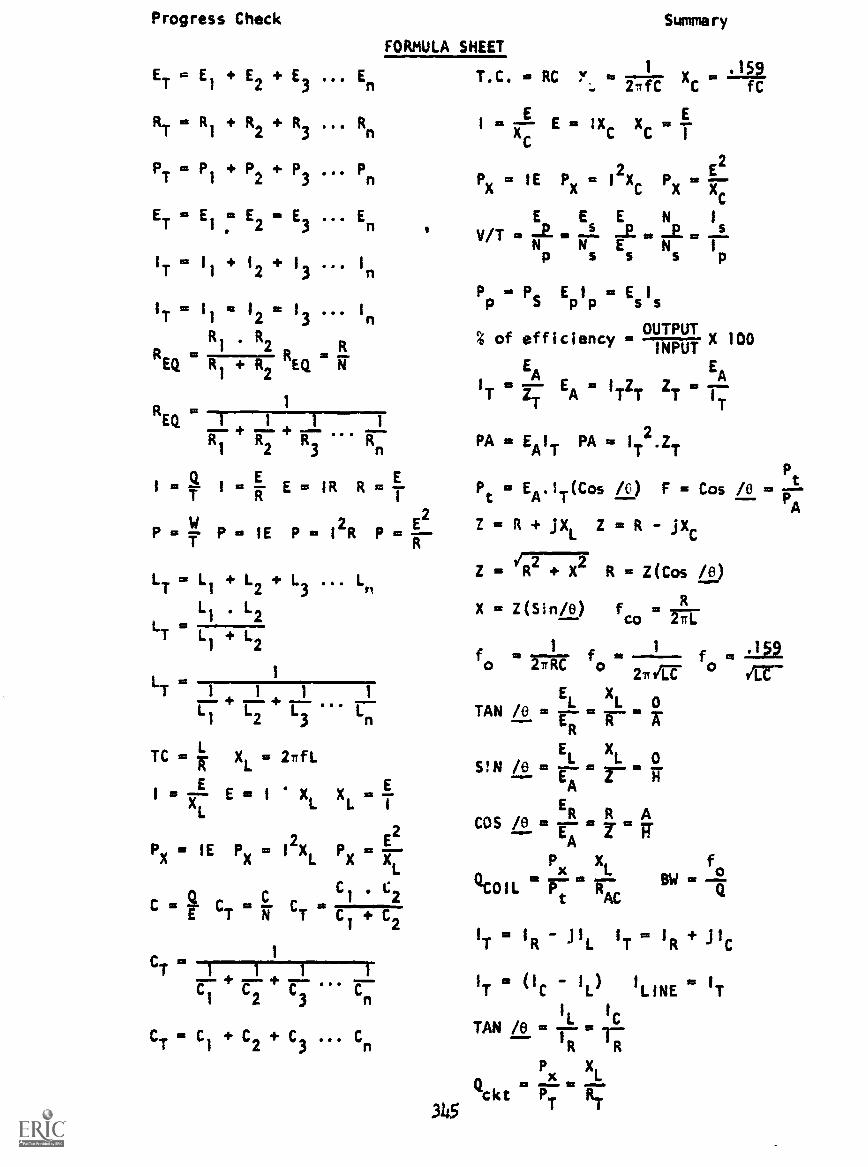
Progress Check
ET = El + E2 + E3 En
RT = R1 + R2 + R3 ... Rn
PTP1
P2 P3 Pn
ET = El1:2
E2= E
3En
IT . 11 + 12 + 13 I
n
I=I a al .. I
TII
213 In
RI
. R2
R R ggiN""'
EQ RI + R2 EQ
1R =EQ T+ 1+ 1
R1
R2
R3
Rn
PA = EA
I
TPA = I
T2.ZT
Pt1= Q 1= E Eco IR 11 =ET R I
Pt = EA. IT (Cos /0 ) F = Cos /0 = Pt
Summary
FORMULA SHEET
1 9T.C. = RC ' = X =
.15
C fC
mXA E= 2Xc Xc = T
PxIE PX= I
2Xc Fix
2
E E E N 1
v/T is so j. -E..N N E N Ip s s s p
Pp = PS Epp
= Es Is
% of efficiencyOUltigIT
X 100
EA r 1 7
EA
IT `A IrT `T IT
2= R + JXL Z = R - jXcP =T P = I E P = I2R P =Er
LT = L1 + L2 + L3 ... Ln
L1
. L2
L =T L
1
+ L2
ffiTI I Ir t- L1 2 3 n
TC = XL = 2rfL
I = 7 E = I
.
X XL = T
E2
Px = IE Px = I
2XL Px = 7-
11-c
CI
. C2C = CT = CT =
I 2
1
CT 1 1 1
C1 r r r IT = (IC IL) 'LINE IT1 2 3
TAN /e =I
L =IC
1--CT = C1 + C2 + C3 ... CnR
L
Z = R R = Z(Cos fe)
X = Z(Sin/e) fc0 .
1 fm 1 ffo nie o
2 itr °m
EL XL0
TAN /0 a
EL xLS! N /8 r r
A
R ACOS /e = ER my - TTA
Qompx XL fo
SW =PT cc
IT = IR - j1L
IT = IR +C
3145
Px XL
Qckt PT RT
Related Documents