PILOT'S HANDBOOK 9900 Series Models 9900, 9900A and 9900B This Revision Incorporates The Multifunction Display Interface Supplement to the Pilot's Handbook

Welcome message from author
This document is posted to help you gain knowledge. Please leave a comment to let me know what you think about it! Share it to your friends and learn new things together.
Transcript

PILOT'S HANDBOOK
9900 Series
Models 9900, 9900A and 9900B
This Revision Incorporates The Multifunction Display Interface Supplement
to the Pilot's Handbook
Copyright 1998 P/N: 32-2302 RYAN INTERNATIONAL CORPORATION Revision: 3 4800 Evanswood Drive • Columbus, Ohio 43229 November 9, 1998
PILOT'S HANDBOOK
9900 Series
Models 9900, 9900A and 9900B
This Revision Incorporates The Multifunction Display Interface Supplement
to the Pilot's Handbook

i
PREFACE ____________________________________ ____________________________________ Thank you for becoming an owner of the Ryan TCAD. You have demonstrated a concern for yourself, those who depend on you for flying safely, and a concern for others who share the airspace around you. Now you can fly with greater confidence, and greater peace of mind, knowing you are equipped with the latest technology available for collision alert. This Operation and Performance Handbook is intended as a guide to the capabilities and operation of the Ryan TCAD 9900 Series. By carefully reading this manual, you will become familiar with TCAD, and how to get the best performance from your investment.
WARNING
The TCAD does not detect all aircraft, and is designed as a backup to the See and Avoid concept, and the ATC Radar
environment. See TCAD Limits in Appendix 2. Refer to this handbook for TCAD limits. CAUTION: This handbook, and the Ryan TCAD, are advisory only. Any action recommended in this manual, or made as a result of data supplied by the TCAD, must be in accordance with applicable FARs and common sense. The pilot in command is the final authority as to the operation of the aircraft.

ii
Features of the Ryan TCAD 9900 Series Feature 9900 9900A 9900B Top and bottom antenna capability for maximum coverage above and below the aircraft
Yes Yes Yes
Selectable Air Traffic Shield – TCAD Electronically monitors for traffic within the airspace you define. You get traffic coverage with minimal distraction!
Yes Yes Yes
Traffic Display - You get the traffic information in the same place, in the same format, in bright LED characters.
Yes Yes Yes
Digital Profile Display with Trend Data – Gives you a quick indication of the significance of the traffic to your safety.
Yes Yes Yes
Additional threat display for additional, less threatening traffic
Yes Yes Yes
Ground mode – Shows traffic in the air before departure without displaying ramp traffic.
Yes Yes Yes
Approach Mode – Eliminates the display of traffic on the ground while on approach.
Yes Yes Yes
iii
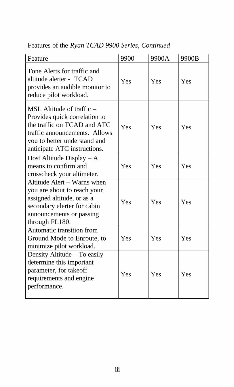
Features of the Ryan TCAD 9900 Series, Continued
Feature 9900 9900A 9900B
Tone Alerts for traffic and altitude alerter - TCAD provides an audible monitor to reduce pilot workload.
Yes Yes Yes
MSL Altitude of traffic – Provides quick correlation to the traffic on TCAD and ATC traffic announcements. Allows you to better understand and anticipate ATC instructions.
Yes Yes Yes
Host Altitude Display – A means to confirm and crosscheck your altimeter.
Yes Yes Yes
Altitude Alert – Warns when you are about to reach your assigned altitude, or as a secondary alerter for cabin announcements or passing through FL180.
Yes Yes Yes
Automatic transition from Ground Mode to Enroute, to minimize pilot workload.
Yes Yes Yes
Density Altitude – To easily determine this important parameter, for takeoff requirements and engine performance.
Yes Yes Yes

iv
Features of the Ryan TCAD 9900 Series, Continued
Feature 9900 9900A 9900B Unrestricted Mode – Enlarges the monitored area and mutes audible alerts until the traffic is closer.
±5000 feet & 3iNM
±10,000 Feet & 6 iNM
±10,000 Feet & 6 iNM
Upgrade Capability – Your TCAD is designed for future enhancement and greater capability
Yes, to 9900A
Yes, to 9900B
Yes, future upgrades
Remote Mute - Yoke mounted mute button if desired.
Yes Yes Yes
½ 3ATI Display - Fits in an instrument location or in the avionics stack.
Yes Yes Yes
Three Programmable Shields – To define the volume of airspace monitored based on aircraft performance and your preferences.
Fixed shield
Yes Yes
Maximum Range – The horizontal limits for tracking traffic around your aircraft.
3 iNM
6 iNM for Mode S targets, 5iNM for Mode A or C
6 iNM for Mode S targets, 5iNM for Mode A or C
Dynamic Shield, displays traffic beyond selected shield during high-speed climbs and descents
Yes Yes Yes
Voice Alert for traffic – Voice warning for traffic alerts.
No Yes Yes

v
Features of the Ryan TCAD 9900 Series, Continued
Feature 9900 9900A 9900B Displays Mode A squawk (when available). To quickly determine if traffic is VFR, IFR, or communicating with ATC.
No Yes Yes
Displays N-number of Mode-S equipped aircraft. Lets you quickly track and correlate the TCAD data with traffic announced on the radio.
No Yes Yes
Provides for Interface with other Multifunction Displays.
No No Yes
Displays bearing to the target for optimal visual tracking.
No No Yes

vi
This Handbook is organized into the Following sections: I Introduction Describes the product, operating concept, technology, and components of the Ryan TCAD 9900 Series. II Operator Controls & Basic Displays Illustrates the controls and display features of the Ryan TCAD 9900 Series. III The Air Traffic Shield Introduces and describes use of the Air Traffic Shield. IV Threat Acquisition Describes recommended procedures when threats are acquired by the TCAD. V Altitude Displays Explains display of MSL altitudes and Flight Levels VI Altitude Alert Describes operation of the Altitude Alert. VII Density Altitude The Density Altitude function is described.

vii
VIII Flying with TCAD Describes operation of TCAD and illustrates a flight from startup to landing. IX Operating Tips Contains useful suggestions to maximize the utility of the Ryan TCAD. X Built-In Test & Fault Displays Describes the TCAD built-in test function and fault displays. Appendix 1 Setup Describes parameters that can be set by the pilot. Appendix 2 Limits Describes limitations of the TCAD and how those limitations can affect performance of the equipment. Appendix 3 Excerpts Presents excerpts from FAA Advisory Circular 90-48C, Pilot's Role in Collision Avoidance. Appendix 4 Contains Specifications, Factory Settings, Warranty, Disclaimer, and Customer Support information. Multifunction Display Interface Supplement (P/N 32-2303) Contains information and operating instructions for TCAD Interface with Multifunction Displays.
viii
Table of Contents ____________________________________ ____________________________________ I Introduction 1 Product Description …………………………… 1 Concept ……………………………………… 2 Technology …………………………………… 3 Components …………………………………… 6 II Operator Controls & Basic Displays 7 Description of Operator Controls …………… 8 Symbols ……………………………………… 10 Audible & Visual Alerts ……………………… 11 Basic Displays ……………………………… 11 III The Air Traffic Shield 15 Terminal, Standard and Enroute Modes ……… 15 Ground Mode ………………………………… 16 Unrestricted Mode …………………………… 17 Approach Mode ……………………………… 17 IV Threat Acquisition …………………………… 21 Bearing to the Traffic ………………………… 21 Visual and non-Visual Acquisition …………… 21 Imminent Alert ……………………………… 22 Multiple Threats ……………………………… 23 Mode A Images ……………………………… 23 Mute …………………………………………… 24 No Altitude Threats …………………………… 24 Data …………………………………………… 24 Update Rate …………………………………… 25 Range ………………………………………… 25 V Altitude Displays 27 Entering Altimeter Setting …………………… 27 Host Altitude Display ………………………… 28 Threat Altitude Display ……………………… 28

ix
VI Altitude Alert 29 Engaging ……………………………………… 29 Disengaging …………………………………… 31 Example ……………………………………… 31 VII Density Altitude 33 Engaging ……………………………………… 33 Entering OAT ………………………………… 34 Disengaging …………………………………… 34 VIII Flying with TCAD 35 Examples of Operation, Model 9900B ………… 35 Examples of Operation Model 9900A ………… 45 Examples of Operation Model 9900 …………… 53 IX Operating Tips 61 Scanning ……………………………………… 61 "No Alt" Replies ……………………………… 62 Range Considerations ………………………… 62 Display Priority ……………………………… 63 Dynamic Shield ……………………………… 64 High Density Operation ……………………… 64 Data …………………………………………… 64 Multiple Threats ……………………………… 65 Monitoring Traffic …………………………… 66 Scalloping ……………………………………… 66 Considerations for Setting Shield Radius ……… 67 Considerations for Setting Shield Height ……… 67 Profile Display ………………………………… 68 Dual Display Operation ……………………… 68 Alert Tones …………………………………… 68 Bearing ………………………………………… 68

x
X Built-In Test & Fault Displays 69 Appendix 1 - Setup 71 Programming ………………………………… 71 Setting the Shield Size ………………………… 71 Tone Options ………………………………… 72 Appendix 2 - Limits 73 Airframe Shadowing ………………………… 73 Signal Reflections …………………………… 74 Overlapped Replies …………………………… 74 Appendix 3 - Excerpts 75 FAA Advisory Circular 90-48C Excerpts …… 75 Appendix 4 85 Specifications ………………………………… 85 Factory Settings ……………………………… 86 Parts and Service Warranty …………………… 87 Customer Support …………………………… 87 Disclaimer …………………………………… 88 Multifunction Display Interface Supplement 89 Index 101

1
SECTION I INTRODUCTION ____________________________________ PRODUCT DESCRIPTION The Ryan TCAD (Traffic and Collision Alert Device) is an on-board air traffic display used to identify potential collision threats. TCAD computes relative altitude and range of threats from nearby Mode C and Mode S-equipped aircraft. Aircraft with non-Mode C transponders can provide range information. TCAD will not detect aircraft without operating transponders. TCAD, within defined limits, creates a shield of airspace around the aircraft, whereby detected traffic cannot penetrate without generating an alert. The shield size is selectable for various phases of flight, and is adjustable by the pilot. The TCAD uses a quickly readable alphanumeric display for threat information. Range is displayed in indicated Nautical Miles (iNM), and relative altitude is displayed in 100-foot increments. The TCAD will display multiple aircraft threats. TCAD is advisory only, and is a back up to the See and Avoid Concept, and the ATC radar environment. Additional functions are provided: DATA and Altitude TCAD will display the identity, transponder code (when available), N-number (Mode S traffic) and MSL altitude of detected aircraft. Indicated Altitude TCAD provides for MSL corrected altitude (or Flight Level) of the host (your) aircraft.

2
Density Altitude Quickly computes density altitude, for determining runway requirements and cruise performance. Altitude Alert Provides tones for approaching a target altitude, and to inform the pilot of inadvertent changes in cruise altitude. CONCEPT Transponder reply signals are generated by aircraft as a result of interrogations. Reply signals near the host aircraft are sensed by the TCAD antenna, and processed by the TCAD computer unit. The nominal range of the threat, determined by the arrival amplitude of the threat aircraft’s transponder signal, is displayed as indicated Nautical Miles (iNM). The vertical separation of the host and threat is determined through decoding of altitude replies. This is important, as effective collision alert makes use of the following principle: "No two aircraft can collide unless they are at nearly the same altitude." This means that any threat approaching from any angle can be avoided by establishing and maintaining vertical separation. Thus, by decoding altitude replies and providing altitude, range and trend data, the TCAD supplies essential information to assist the pilot in making an avoidance decision.

3
Any threat approaching from any angle...
...can be avoided by establishing and maintaining vertical separation.
TECHNOLOGY Since the 1950s, researchers have sought methods to alert pilots of collision threats. Reply signals from airborne beacon transponders are the accepted basis for effective collision alert. When transponders are interrogated by TCAS equipped aircraft, military radar sites, or civilian radar sites, reply signals are transmitted. The Ryan TCAD receives and processes these signals from nearby aircraft to provide traffic alert information. Altitude separation is determined by comparing the altitude replies from the threat aircraft with the onboard altitude encoder of the host aircraft. The altitude reply from the threat is referenced to 29.92 inches (pressure altitude), as
4
is the onboard encoder, thus providing meaningful separation information. The difference in altitude is displayed with a plus or minus symbol, indicating that the traffic shows above or below your encoded altitude. TCAD monitors the altitude difference and displays a closing symbol when the difference becomes smaller, and a parting symbol when the difference becomes larger, thus providing altitude trend information. No trend symbol means the altitude separation is not changing. Altitude separation is critical for effective collision avoidance.
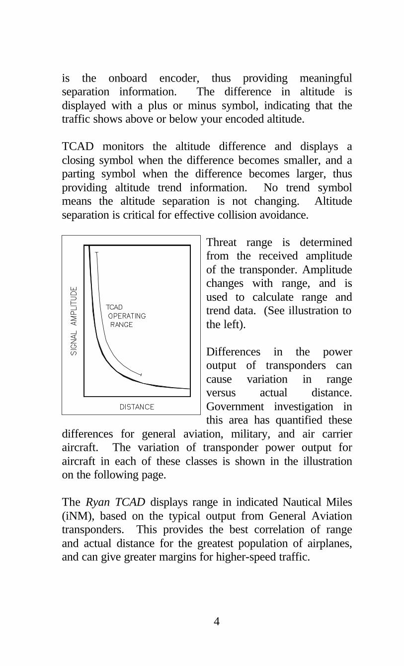
Threat range is determined from the received amplitude of the transponder. Amplitude changes with range, and is used to calculate range and trend data. (See illustration to the left). Differences in the power output of transponders can cause variation in range versus actual distance. Government investigation in this area has quantified these
differences for general aviation, military, and air carrier aircraft. The variation of transponder power output for aircraft in each of these classes is shown in the illustration on the following page. The Ryan TCAD displays range in indicated Nautical Miles (iNM), based on the typical output from General Aviation transponders. This provides the best correlation of range and actual distance for the greatest population of airplanes, and can give greater margins for higher-speed traffic.

5
The increase or decrease of range data shows the trend in range. This trend information, particularly in closure situations, is important for effective collision alert, and is essentially independent of power variations among transponders. The TCAD displays threats detected within a predetermined volume of airspace (the Air Traffic Shield). The size of the shield can be selected by the pilot, based on anticipated traffic conditions, using the TRML, STD, and ENRT mode buttons. Additionally, the pilot can program the size of the shield in each mode. Multiple threats within the shield are prioritized and displayed based on range and altitude separation. Secondary and third level threats are indicated by symbols and can be displayed at the operator's discretion.

6
COMPONENTS The Ryan TCAD 9900 Series consists of three basic components: the Display, remote Processor and Transponder Coupler. An optional second Display is available for two-pilot operations, and two couplers are normally used when the aircraft has two transponders.
The Display contains 20 bright-character LED elements and all controls for operation of the TCAD. The Processor contains dual high-performance microwave receivers, and an advanced high-speed computer. The Transponder Coupler is included to interface with the onboard transponder. The TCAD antennas are aerodynamically designed blade antennas mounted on the top and bottom of the aircraft.

7
SECTION II OPERATOR CONTROLS & BASIC DISPLAYS ____________________________________ ____________________________________ The TCAD 9900 Series display uses 20 LED cells to communicate visual information to the pilot. Audible tones and selectable voice annunciation provide aural warnings. Audible warnings are used to call attention to a detected threat within the monitored airspace. The Altitude Alert generates a distinctive short tone to call attention to an approaching target altitude, or altitude deviation. Plus and minus symbols are used to indicate the vertical direction of a threat. Altitude trend information is shown by the use of a closing symbol (two triangles pointing together in an hourglass shape) and by a parting symbol (two triangles pointing apart in a diamond shape). A letter in the lower right-most cell of the display (the mode cell) indicates the mode (TRML, STD, or ENRT). The letter "U" or "G" in the mode cell indicates a special sub-mode has been selected. (See Section III). One (or two) aircraft symbols to the right of a traffic display indicate that a second (or third) threat has been detected and is available for display. The s button is used to momentarily display the secondary threat, and the t button is used to display the third-level threat. When the secondary threat display is selected, the aircraft symbol reverses (i.e. from a light aircraft on a dark background to a dark aircraft on a light background) to clearly indicate which threat is being displayed.
8
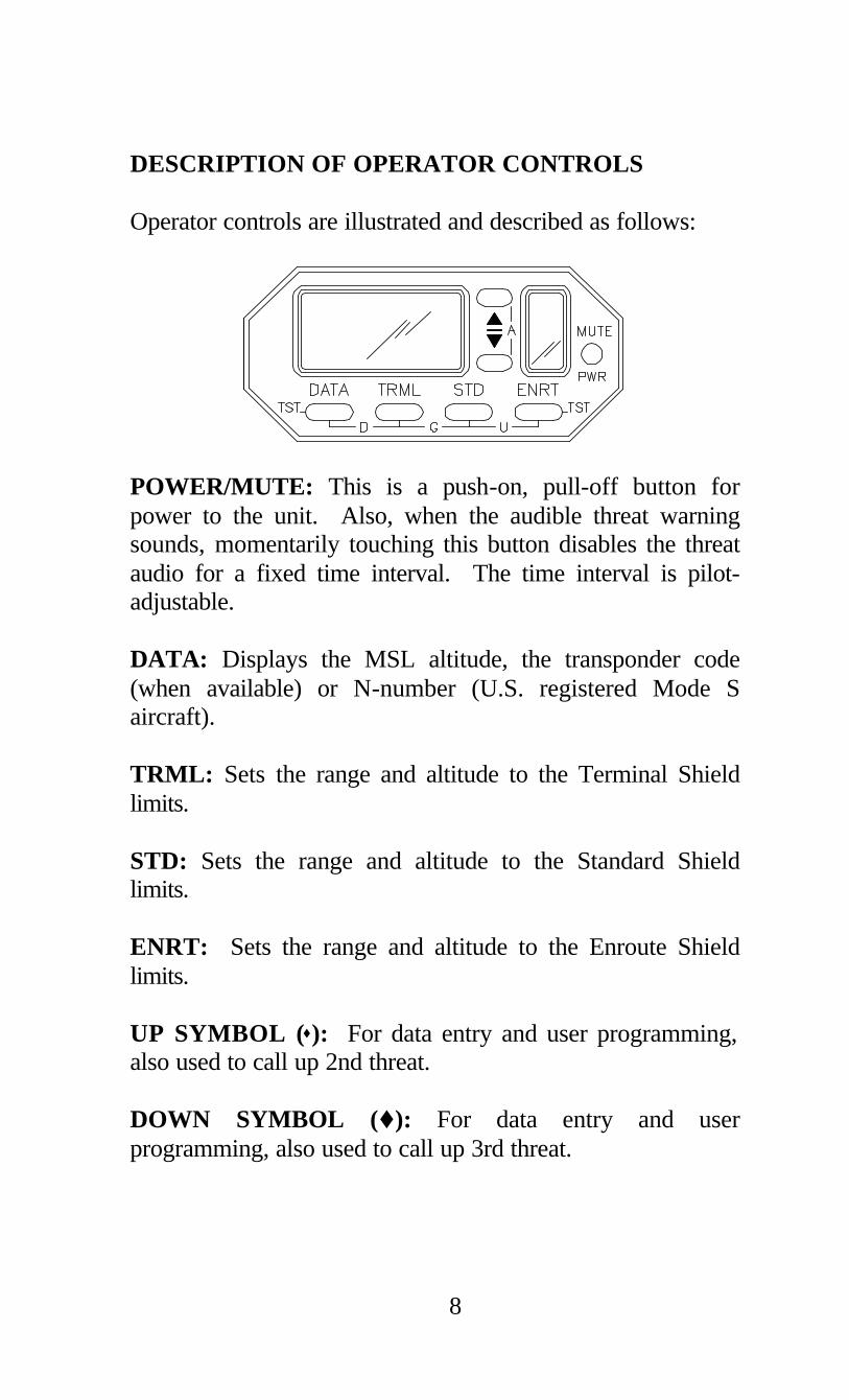
DESCRIPTION OF OPERATOR CONTROLS Operator controls are illustrated and described as follows:
POWER/MUTE: This is a push-on, pull-off button for power to the unit. Also, when the audible threat warning sounds, momentarily touching this button disables the threat audio for a fixed time interval. The time interval is pilot-adjustable. DATA: Displays the MSL altitude, the transponder code (when available) or N-number (U.S. registered Mode S aircraft). TRML: Sets the range and altitude to the Terminal Shield limits. STD: Sets the range and altitude to the Standard Shield limits. ENRT: Sets the range and altitude to the Enroute Shield limits. UP SYMBOL (s): For data entry and user programming, also used to call up 2nd threat. DOWN SYMBOL (t): For data entry and user programming, also used to call up 3rd threat.
9
Pressing two buttons simultaneously accesses five functions. UP SYMBOL (s) & DOWN SYMBOL (t): These buttons, engage or disengage the Altitude Alerter (-A-). See Section VI. DATA & TRML: By pressing these two buttons, the Density Altitude function (-D-) is engaged or disengaged (See Section VII). TRML & STD: By pressing these two buttons, the Ground Mode (-G-) is engaged (See Section III). STD & ENRT: By pressing these two buttons, the Unrestricted Mode (-U-) is engaged (See Section III). DATA & ENRT: By pressing these two buttons, the Built-in Test function (-TST-) is initialized (See Section X). TRML & MUTE: By pressing these two buttons, the Approach Mode set-up is accessed (See Section III).

10
SYMBOLS Special symbols displayed on TCAD are shown below:

11
AUDIBLE & VISUAL ALERTS Voice, tones and an optional annunciator light are used to alert the pilot. The alerts used by TCAD are: SINGLE A non-repetitive alert for detected
traffic within monitored airspace. IMMINENT A repetitive alert for detected ALERT traffic within ±500 feet and 1 iNM, and a faster repetition when within ±300 feet and 0.7 iNM When voice alerts are enabled (Model 9900A and 9900B), the last tone is replaced by the word “Traffic”. TCAD will alarm once for each target tracked outside the Imminent Alert airspace. The optional annunciator light will illuminate whenever traffic is shown on the display. The terms “audible alert” and “tones” are used interchangeably in this manual and, when referenced to traffic, mean the audible traffic warning used by TCAD. A unique reverberating tone is used for the Altitude Alerter. BASIC DISPLAYS There are two basic displays on the Ryan TCAD: l When the unit is searching, and l When a threat is acquired. The following illustrations show typical displays and associated controls:

12
Search Configuration
¬ TCAD is searching for a threat.
Aircraft altitude.
® Self Test Cursor ¯ Mode indicator (shown indicating Enroute Mode). ° Used to adjust TCAD parameters,
barometric pressure (altimeter setting); and to engage or disengage the Altitude Alert.
± "A" - Altitude Alert engaged. ² "M" - displayed when tones are muted. ³ Mutes audible tones for a specified duration,
and push/pull for on/off. È Used to select mode, and for initiating
barometric pressure adjustment prior to using the s and t buttons.

13
Threat Acquisition
¬ Range is 2.1 indicated Nautical Miles and approximately 1:30. ( the arrow is on the Model 9900B only).
Traffic is 300 feet above, converging
in altitude. ® Mode indicator (Terminal Mode). ¯ s Used to display secondary threat. t Used to display third level threat. ° Second and third level threats. Flashing
shows nearby and opposite in altitude (See Section IV).
± Mutes audible tones for a specified duration,
and push/pull for on/off. ² Used to select shield size. ³ Displays additional data about
the displayed threat.

14
This page intentionally left blank.
15
SECTION III THE AIR TRAFFIC SHIELD ____________________________________ ____________________________________ The optimum volume of airspace to be monitored by TCAD changes with traffic density. When traffic is light, and aircraft are at cruising speeds, a large volume of airspace should be monitored. In higher-density airspace, when the pilot is more alert for traffic and speeds are limited, a smaller surveillance volume is generally appropriate. “Air Traffic Shield” describes an adjustable volume of airspace, controlled by the pilot, to display potential threats, yet prevent extraneous traffic from being displayed. The Air Traffic Shield has a specified radius and height above and below the aircraft, where a detected threat normally cannot enter without generating an alert. TERMINAL, STANDARD & ENROUTE MODES The Ryan TCAD provides three quickly selectable shield volumes, designated as the Enroute (ENRT), Standard (STD) and Terminal (TRML) modes. When the host aircraft is at cruise, ENRT is selected. A large volume of airspace should be monitored because traffic is usually light, and threats could approach at high speeds and high rates of climb or descent. STD would typically be selected when the host aircraft transitions from enroute flight. Traffic usually becomes more dense and the speed of potential threats is usually lower. Therefore a smaller shield size would be appropriate. Similarly, TRML would be selected when in the terminal area, because a smaller volume of airspace is generally best, in order to display threats and prevent display of extraneous traffic.
16
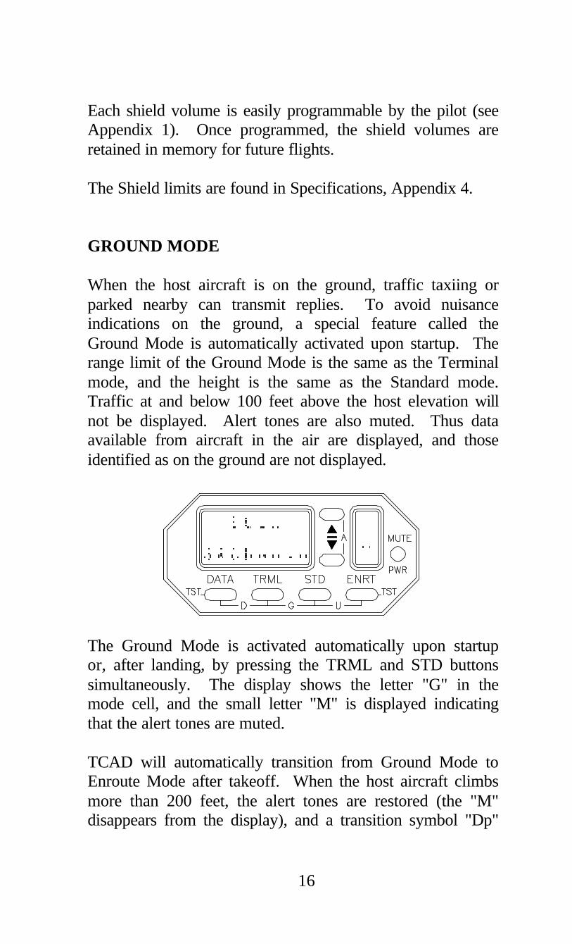
Each shield volume is easily programmable by the pilot (see Appendix 1). Once programmed, the shield volumes are retained in memory for future flights. The Shield limits are found in Specifications, Appendix 4. GROUND MODE When the host aircraft is on the ground, traffic taxiing or parked nearby can transmit replies. To avoid nuisance indications on the ground, a special feature called the Ground Mode is automatically activated upon startup. The range limit of the Ground Mode is the same as the Terminal mode, and the height is the same as the Standard mode. Traffic at and below 100 feet above the host elevation will not be displayed. Alert tones are also muted. Thus data available from aircraft in the air are displayed, and those identified as on the ground are not displayed.
The Ground Mode is activated automatically upon startup or, after landing, by pressing the TRML and STD buttons simultaneously. The display shows the letter "G" in the mode cell, and the small letter "M" is displayed indicating that the alert tones are muted. TCAD will automatically transition from Ground Mode to Enroute Mode after takeoff. When the host aircraft climbs more than 200 feet, the alert tones are restored (the "M" disappears from the display), and a transition symbol "Dp"
17
replaces the Ground Mode symbol. The shield dimensions expand by holding the bottom of the shield at 200 feet above the departure elevation, and the top of the shield climbs as the aircraft climbs. The monitored airspace height expands until the ENRT Mode shield size is reached. Then the symbol in the Mode cell changes to an "E" indicating Enroute Mode. Some encoders require a warm-up period before valid data are available. When in the Ground Mode, initialization will automatically halt at the altimeter adjustment until the encoder indicates it is supplying valid data. CAUTION: Do not operate TCAD in the Ground Mode
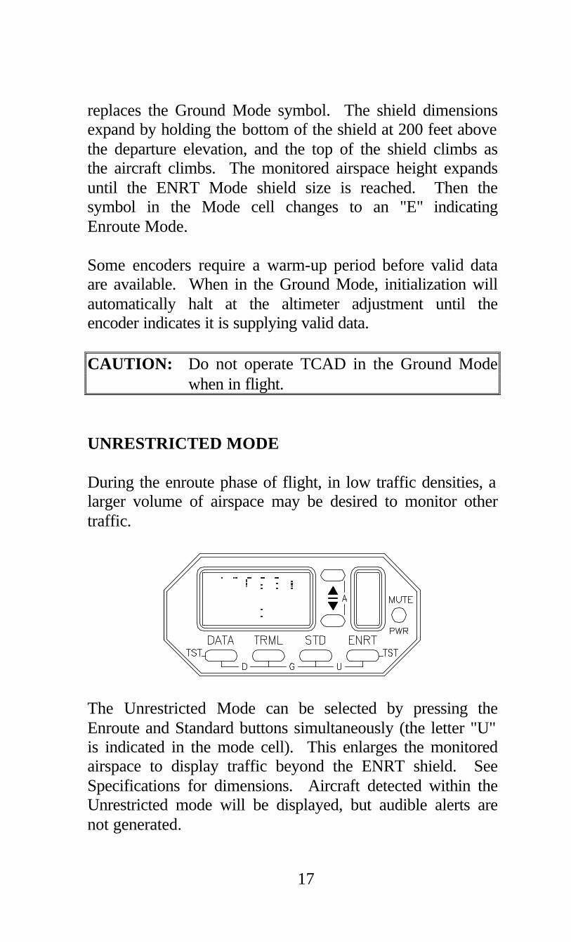
when in flight. UNRESTRICTED MODE During the enroute phase of flight, in low traffic densities, a larger volume of airspace may be desired to monitor other traffic.
The Unrestricted Mode can be selected by pressing the Enroute and Standard buttons simultaneously (the letter "U" is indicated in the mode cell). This enlarges the monitored airspace to display traffic beyond the ENRT shield. See Specifications for dimensions. Aircraft detected within the Unrestricted mode will be displayed, but audible alerts are not generated.

18
The annunciator light, if installed, will illuminate when traffic is displayed. When traffic is detected in the ENRT shield, TCAD will generate a tone and automatically return to the Enroute Mode. APPROACH MODE The Approach Mode automatically eliminates tones caused by aircraft on the ground as the TCAD-equipped airplane approaches the runway. Approach Mode is similar but opposite to the Ground Mode. As the host aircraft descends, the shield size becomes smaller, and upon landing TCAD enters the Ground Mode. TCAD must be supplied with the destination elevation to use the Approach Mode. Before landing, the pilot can access the Approach mode by pressing the MUTE and the TRML buttons (thus Muting the Terminal). The status window shows "APCH". The top line of the TCAD display shows "FldElev:", and the lower line shows ">>xx00ft" (xx is normally the elevation previously set into this mode). The up and down buttons can be used to enter the destination field elevation. Pressing the mute button again restores TCAD to the previously selected mode (or eight seconds elapsed time will automatically return TCAD to the previously selected mode).

19
As the aircraft descends, and the lower limit of the Enroute shield is within 100 feet of the selected field elevation, TCAD automatically enters the Approach Mode, as shown by "Ap" in the Mode cell. As the aircraft continues descent, the shield limits will change from Enroute through Standard until the shield reaches the lateral limits of the TRML mode, and the vertical limits of the STD mode. Then, the vertical limit of the shield below the aircraft will become smaller so as to not display traffic on the ground and at +100 feet AGL. When the airplane descends to within 100 feet of the field elevation, TCAD transitions to the Ground mode where threat tones are muted, as indicated by the "M" in the status window, and "G" in the Mode cell. When preset, TCAD automatically enters Approach Mode from Terminal, Standard, Enroute, or Unrestricted Mode. The Approach Mode can be set at any time, but will engage only when the bottom of the selected shield is greater than 300 feet above the selected field elevation.

20
This page intentionally left blank.

21
SECTION IV THREAT ACQUISITION ____________________________________ ____________________________________ The following paragraphs describe the threat acquisition portion of TCAD operation, and include information on visually acquiring traffic, and situations that will be encountered in TCAD operation. BEARING TO THE TRAFFIC (Model 9900B) The TCAD Model 9900B uses a patented antenna system and four receivers to provide bearing to the traffic. An arrow on the display shows the direction to aid in visually locating the traffic. The direction of the traffic is determined using the top and bottom antennas. Each antenna provides basic directional information, and a minimum level signal from the opposing antenna resolves any ambiguity. TCAD presents traffic information in a plan-view format on Multifunction Displays. For more information, see the Supplement at the end of this manual. Contact Ryan International Corporation for a current list of compatible displays. NOTE: TCAD diagnostics monitor for bearing reliability. When the 9900B detects a low-reliability bearing signal, the bearing arrow will momentarily disappear. All other information will continue to be displayed. VISUAL AND NON-VISUAL ACQUISITION (Model 9900 and 9900A) When TCAD detects traffic, and the alert sounds, the pilot should view the TCAD display and determine the vertical

22
separation and range between the host and threat aircraft. The pilot should then visually scan forward of the aircraft, as the warning time is shortest for head-on traffic. If the displayed data does not suggest urgent action, the pilot should continue to scan, giving priority to the region ahead. If the vertical separation is small, and the range is decreasing, the pilot should take steps to establish the location of the traffic and maintain vertical separation. More typically, there will be sufficient altitude separation, and sufficient range, so that immediate pilot reaction is not necessary for safety. Knowing the altitude separation, visual scanning can be restricted to the appropriate elevation from the aircraft. Note: The minimum range indication on TCAD is 0.0 iNM. CAUTION: The traffic you see may not be the traffic the TCAD has detected. Continue to monitor the TCAD and visually scan outside even after the traffic is observed. IMMINENT ALERT Repetitive warning tones are provided when traffic is very close. Traffic detected within ±500 feet and 1.0 iNM will generate a double tone that repeats at approximately two- second intervals. When the traffic is detected within ±300 feet and 0.7 iNM, a triple tone is generated at approximately one-second intervals. When voice alerts are enabled, the last tone is replaced by the word “Traffic”.

23
MULTIPLE THREATS TCAD can monitor more than 50 aircraft at one time, and displays up to three. When a second (or third) threat is detected in the monitored area, one (or two) small airplane symbols appear in the right display window. Data on second and third threats can be momentarily displayed by pressing the s button or t button adjacent to the aircraft symbols (See Section IX, Operating Tips). If the first and second threats are above the host aircraft, both threats can be avoided by descending. Similarly, if both are below the host aircraft, the threats can be avoided by ascending. If the primary threat is above the aircraft and the second threat is below the aircraft (or vice versa), and are within 500 feet of the host, avoiding one could position the other threat closer to the host airplane. If this situation exists, and the detected aircraft are within 1 iNM, the small airplane symbol will flash, indicating a need to view the secondary display before deciding on a course of action. Generally, the shield size should be reduced when three threats are detected within the monitored area. MODE A IMAGES The Ryan TCAD processing function decodes and pairs Mode A and C replies from threat aircraft, and sends the data on to be prioritized and displayed. A few ATC assigned Mode A codes are identical to Mode C codes, making it difficult for the processor to determine which of the A/C pair is the Mode A and which is the Mode C. In this case, both combinations are prioritized and displayed. If the threat aircraft or Mode A image is within the shield, it will be displayed. In the unlikely event that both the Mode A image and the threat are detected inside the monitored area, the combination is treated as a multiple threat.

24
MUTE The mute button silences audible warnings for a specified duration. When activated, an upper case "M" appears on the display. Mute does not disable Altitude Alert tones. The mute time is pilot adjustable (see Appendix 1). Pressing the mute button when mute is activated will restore the audible alerts. NO ALTITUDE THREATS The TCAD can detect aircraft without altitude-reporting capability. In this case, TCAD provides iNM and horizontal closure information. TCAD will display NO ALT along with the iNM (See "No ALT" Replies in Section IX). When the host aircraft is above 12,000 feet pressure altitude, non-Mode C traffic is not displayed. DATA Pressing the DATA button when a threat is shown will display the altitude and identity code of the threat. This can be helpful to determine if the traffic is VFR, VFR handled by ATC, or has an IFR squawk. When a Mode S target is acquired, the N-number of U.S. registered Mode S aircraft is displayed instead of the transponder code. The transponder code of the traffic is a secondary function, while altitude and iNM are primary. In many situations, especially in high-density areas, TCAD will not acquire the transponder code. If the code is not available, ‘Mode A/C’ or ‘Mode A’ will be displayed. The code of non-Mode C traffic can also be displayed.

25
UPDATE RATE TCAD is updated by transponder replies from threat aircraft. The rate of update is directly related to the density of the Secondary Surveillance radar environment and the interrogations from TCAS-equipped aircraft. The transponder reply light provides an indication of the update rate. RANGE TCAD uses signal strength to determine the range of traffic. Variations in output power from the opposing traffic will affect the iNM correlation to actual distance, and is most pronounced at ranges beyond three iNM. Closure information should be the primary determinant of a threat beyond three iNM. See Section IX for more information.

26
This page intentionally left blank.

27
SECTION V ALTITUDE DISPLAYS ____________________________________ ____________________________________ When the current ATC-supplied altimeter setting is entered into TCAD, the digital altitude display shown is the same as the altitude shown for your aircraft at the ATC facility. In addition, when a threat has been acquired and the DATA button is pressed, the MSL altitude (or flight level) and ATC assigned transponder code of the threat will be displayed. Note: The altimeter setting does not need to be entered for collision alert operation. Since both the host and threat aircraft are transmitting pressure altitude, displayed altitude separation is not affected by the altimeter setting. ENTERING ALTIMETER SETTING The barometric pressure can be adjusted by pressing any mode button, then the up or down symbol button. Normal operation will resume after releasing the button. Note: The TCAD is not processing traffic information while the altimeter setting buttons are depressed. TCAD has returned to collision alert operation when the "SRCHNG" display appears. If TCAD detects invalid encoder data, altitude is not displayed on TCAD, and traffic separation information is not available. CAUTION: Altitude encoders and altimeters are not always accurate, and could lead to errors in the information provided to TCAD. Be sure that your altimeter and encoder are accurate, and maintain enough separation when traffic is encountered.

28
HOST ALTITUDE DISPLAY The MSL altitude or the flight level of the host aircraft is displayed in the search configuration. Below 18,000 feet, the TCAD barometric correction can be adjusted to the local altimeter setting. At 18,000 feet and above, the altimeter automatically adjusts to 29.92 inches, and the display will show Flight Level instead of altitude in feet. When the local altimeter is lower than 29.92 inches, FL 180, (and sometimes FL 190) does not exist. TCAD will not display flight levels until the barometric correction in the TCAD indicates that Flight Level display is appropriate. On descent, the local altimeter setting can be preset, and when the aircraft descends below the flight levels, the MSL altitude will be displayed. If the altitude features are not used, a barometric setting of 29.92 inches is recommended for the TCAD. THREAT ALTITUDE DISPLAY The altitude of the threat aircraft is displayed when the DATA button is pressed. TCAD will provide the MSL altitude of the traffic (corrected to the barometric pressure setting in the TCAD), or the Flight Level, as appropriate. See Section VIII, Flying with TCAD. CAUTION: Altitude information provided by the Ryan TCAD is advisory only and is not to be used for dispatch purposes.

29
SECTION VI ALTITUDE ALERT ____________________________________ ____________________________________ In the Air Traffic Control environment, an unauthorized deviation in assigned altitude can compromise safety. The Ryan TCAD provides a means to alert the pilot prior to arrival at an assigned altitude, or inadvertent changes in cruise altitude. ENGAGING The Altitude Alert function is activated by pressing the s and t buttons simultaneously. When this is done, ALT SET: is displayed on the upper display line, with the last entered altitude appearing on the lower line.
The s and t buttons can be used separately to adjust the displayed altitude to an assigned or desired altitude (or flight level). If no button presses occur for 8 seconds, the Altitude Alert will engage at the displayed altitude, and TCAD will return to the collision alert display. If desired, the Altitude Alert can be manually engaged by pressing the s and t buttons simultaneously while the ALT SET: message is displayed.

30
When the Altitude Alert is engaged, a small upper case "A" appears on the display. A reversed-image "A" is shown prior to arrival at the target altitude, and a normal "A" is shown when on the target altitude (See Symbols, Section II). When the Altitude Alert is set for a target altitude and engaged, a short tone will announce that the aircraft has arrived within 500 feet of the target altitude. At the selected cruise altitude, a change of 200 feet will generate an altitude deviation tone. The aircraft must then return to the selected cruise altitude to re-engage the altitude alert tones. Note: The altitude encoder provides information in 100-foot increments. Therefore, when the encoder trips the second 100-foot increment, the tone will sound. Note: The TCAD continues to operate in the Collision Alert configuration when the Altitude Alert is engaged. CAUTION: TCAD operates in the Collision Alert configuration except while the Altitude Alert is being set. When adjusting the Altitude Alert, large steps to the vicinity of the selected altitude can be made by pressing the TRML or STD button.

31
DISENGAGING The Altitude Alert function can be disengaged by pressing the s and t buttons simultaneously. The "A" symbol will disappear from the display. The Altitude Alert will automatically disengage if the aircraft changes 1000 feet from a set altitude. EXAMPLE
¬ Cleared to climb and maintain 11,000 feet. The pilot activates the Altitude Alert by pressing the s and t buttons. The s button can be used to set the assigned altitude of 11,000 feet. The display shows ALT SET: 11000FT, then engages following a short wait (or manually engaged by pressing both the s and t buttons when ALT SET: 11000FT is displayed). As the aircraft passes through 10,500 feet, a tone is issued. ® If the aircraft deviates from 11,000 feet, a tone sounds.

32
¯ Cleared to descend and maintain 7,000 feet. Reset the
Altitude Alert by Pressing the s and t buttons twice, once to disengage, and again to activate. The pilot uses the t button to set the assigned altitude of 7,000 feet. After 8 seconds, Altitude Alert engages (or manually engaged as before).
° A tone will sound at 7,500 feet as a reminder to level at 7,000 feet.

33
SECTION VII DENSITY ALTITUDE ____________________________________ ____________________________________ Density Altitude is useful for calculating powerplant performance at cruise, and for calculating runway requirements for high altitude, high temperature departures. Density Altitude is determined from pressure altitude and temperature. The Ryan TCAD receives pressure altitude from the onboard altitude encoder. By manually entering the outside air temperature (OAT), the TCAD can compute and display the Density Altitude. ENGAGING The Density Altitude function is engaged by simultaneously pressing the DATA and TRML buttons. The display will show the previously entered temperature (in degrees F or degrees C) and the Density Altitude corresponding to that temperature and aircraft pressure altitude. The Density Altitude function can be engaged anytime. Note: Some altitude encoders have a warm-up period of as much as 10 minutes before the correct altitude is reported. Be sure that your encoder is supplying the TCAD with proper pressure altitude. CAUTION: The TCAD does not operate in the collision alert function when computing and displaying Density Altitude.

34
ENTERING OAT By depressing the s or t button while engaged in the Density Altitude function, the Outside Air Temperature (OAT) on the TCAD can be adjusted to reflect the OAT as reported, or as shown on the OAT gauge. The Density Altitude corresponding to the displayed temperature and aircraft altitude is computed and displayed.
Note: TCAD does not measure the actual Outside Air Temperature. The operator must adjust TCAD to reflect the OAT. The OAT can be adjusted using a degrees Fahrenheit (F) format or a degrees Celsius (C) format. Press the DATA button to toggle between Fahrenheit and Celsius. When Density Altitude is selected, the display defaults to the previously entered temperature and format. Pressing the TRML or STD button can make large steps to the vicinity of the desired OAT. DISENGAGING The TCAD can be returned to the collision alert function by pressing the DATA and TRML buttons. If no button is pressed for 8 seconds, the TCAD will automatically return to collision alert operation.

35
SECTION VIII FLYING WITH TCAD ____________________________________ ____________________________________ TCAD tracks altitude separation, altitude closure, range and range trend of threat aircraft. The following sequences could be encountered during a typical flight with TCAD. Other sections of this Handbook explain set up of pilot programmable functions, use of the Altitude Alert and Density Altitude features, and Built-in Test. There are three examples of operation in this section, one for each model of the 9900 Series. EXAMPLES OF OPERATION, Model 9900B Power has been applied, and TCAD has completed the initialization sequence. The altimeter setting can be entered if desired.
In the illustration above, current altimeter is 30.14" and the field elevation is 1,700 feet MSL. After a few seconds, TCAD will enter a collision alert configuration (Search or Threat Acquisition). The altimeter setting does not need to be correct for effective collision alert operation, but it can be very helpful (see Section V).

Examples of Operation, Model 9900B
36
The shield sizes could be reset (see Appendix 1), but it is not necessary to adjust them before each flight. For this example, the shield sizes are those set at the factory (see Appendix 3).
This illustration shows TCAD has automatically entered the Ground Mode, and is operating in the Search Configuration. All tones are muted (hence the "M") and aircraft at and below 100 feet above the host aircraft’s encoded altitude are not displayed (see Section III for more on Ground Mode). An ATC clearance is received, providing initial clearance to 4,000 feet. The Altitude Alert can be set for 4,000 feet (see Section VI). When passing through 3,500 feet, a tone will sound as a reminder of arrival at the assigned altitude. When the Altitude Alert is engaged, a small upper case reversed-image "A" will appear on the display as illustrated above. If Density Altitude is of concern for takeoff, depressing the DATA and TRML buttons and entering the Outside Air Temperature (OAT) can provide this (see Section VII).

Examples of Operation, Model 9900B
37
Before takeoff, check the area visually for traffic and check the TCAD. TCAD is indicating traffic 400 feet above, closing in altitude, 0.8 iNM away, approximately 1:30. The traffic is then visually acquired on a close-in base to final, and lands before your departure. Note the "G" in the lower right-most cell, indicating Ground Mode.
WARNING TCAD may not detect all traffic on approach. Always check
the area visually before departing.
After climbing more than 200 feet, the "M" disappears, indicating that the alert tones are enabled. The mode symbol changes to "Dp", indicating departure transition, until the aircraft climbs above the programmed base of the Enroute Mode (see Section III). ). If a high-rate climb were made, the Dynamic Shield would expand to monitor for traffic above the set shield. Note the reversed-image "A" remains, indicating that the Altitude Alert is set.

Examples of Operation, Model 9900B
38
Passing through 2,900 feet, “traffic” sounds. The traffic shows 500 feet above the host aircraft, closing in altitude, 1.0 iNM, at approximately 10:30. The iNM is getting smaller, indicating closure in range. The traffic is visually acquired to the left front, descending. Continue to monitor traffic and maintain climb or increase rate of climb.
TCAD shows the closest point of approach, 200 feet below and 0.5 iNM off the left wing. The altitude separation and range then increase. Note the automatic transition to the Enroute Mode.
Traffic continues to descend, and passes to the left.

Examples of Operation, Model 9900B
39
At 3,500 feet, the Altitude Alert sounds indicating the aircraft is nearing 4,000 feet. At 4,000 feet the reversed-image "A" changes to a normal "A".
Traffic is acquired 1,000 feet above at 2.5 iNM, approximately 12:00 o’clock. The traffic is 1000 feet higher and showing level, so it is likely not a threat.
Pressing the DATA button reveals the traffic to be VFR at 5,000 feet MSL.

Examples of Operation, Model 9900B
40
The traffic continues to close in range, and has changed slightly in altitude. The traffic is acquired visually.
The traffic continues to approach, and is nearly overhead.
The traffic flies directly overhead and passes behind. You are instructed by ATC to turn 45° to the right.

Examples of Operation, Model 9900B
41
Eventually the traffic, which has climbed to 1200 feet above, leaves the monitored area.
Cleared out of 4,000 feet for Flight Level 210. Reset the Altitude Alert to FL 210.
Passing through 10,000 feet, the alert sounds. TCAD shows traffic 1,400 feet below, closing in altitude at 2.8 iNM, off the left wing. Since the threat is closing in altitude, it is also climbing.

Examples of Operation, Model 9900B
42
The altitude separation is getting smaller, but the iNM is slowly increasing, and the traffic is still at about 9:00 o’clock. The traffic is flying a nearly parallel course.
Pressing the DATA button reveals the target has a Mode A/C transponder, but no squawk has been acquired. ATC verifies the traffic climbing to 9000 feet.
Leveling at FL 210, the Unrestricted Mode is selected (see Section III). Traffic is displayed 8,000 feet above and 5.3 iNM, aft and to the left.

Examples of Operation, Model 9900B
43
DATA shows the traffic as N864UA, likely airline traffic. Later, the Approach Mode is set in anticipation of descent and landing (See Section III).
Descending now, TCAD automatically transitions to the Approach Mode (shown by the “Ap” in the lower right). If a high-rate descent is made, the Dynamic Shield would expand to monitor for traffic below the set shield. The alert sounds, and TCAD shows traffic 1,000 feet above, closing, 2.0 iNM at approximately 10:30. The traffic is then visually acquired. A short time later, ATC reports the traffic.
The traffic now shows 500 feet above, 1.5 iNM, about 9:00 o’clock. A second threat has entered the monitored area.
Examples of Operation, Model 9900B
44
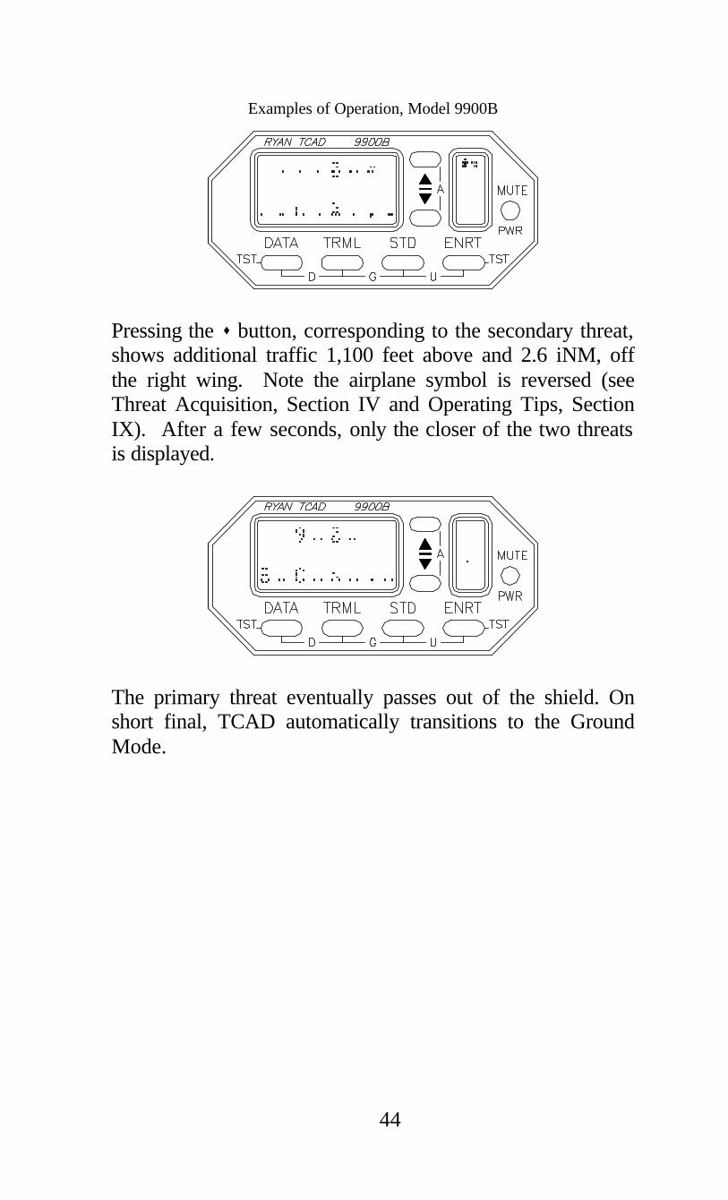
Pressing the s button, corresponding to the secondary threat, shows additional traffic 1,100 feet above and 2.6 iNM, off the right wing. Note the airplane symbol is reversed (see Threat Acquisition, Section IV and Operating Tips, Section IX). After a few seconds, only the closer of the two threats is displayed.
The primary threat eventually passes out of the shield. On short final, TCAD automatically transitions to the Ground Mode.
45
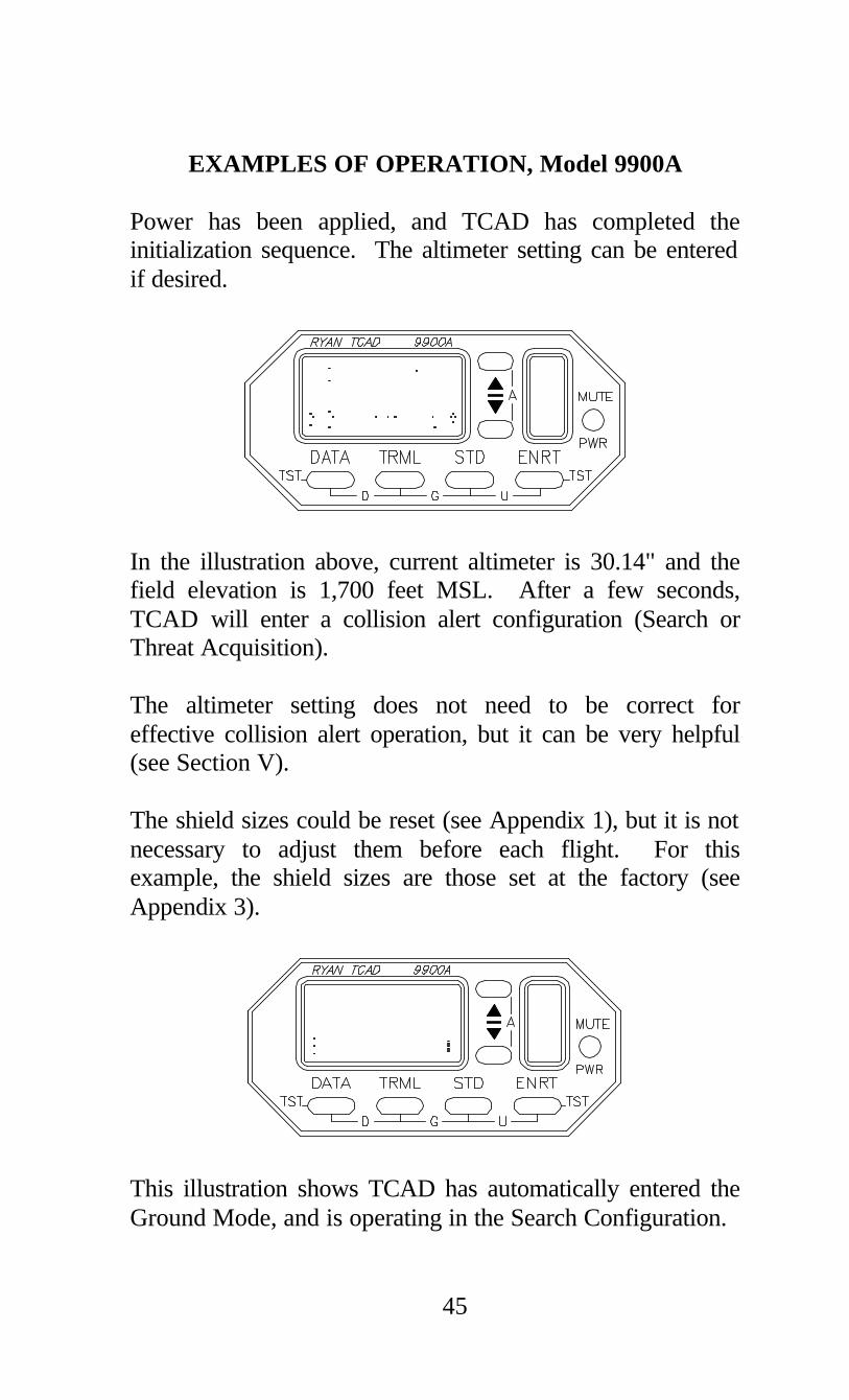
EXAMPLES OF OPERATION, Model 9900A Power has been applied, and TCAD has completed the initialization sequence. The altimeter setting can be entered if desired.
In the illustration above, current altimeter is 30.14" and the field elevation is 1,700 feet MSL. After a few seconds, TCAD will enter a collision alert configuration (Search or Threat Acquisition). The altimeter setting does not need to be correct for effective collision alert operation, but it can be very helpful (see Section V). The shield sizes could be reset (see Appendix 1), but it is not necessary to adjust them before each flight. For this example, the shield sizes are those set at the factory (see Appendix 3).
This illustration shows TCAD has automatically entered the Ground Mode, and is operating in the Search Configuration.
Examples of Operation, Model 9900A
46
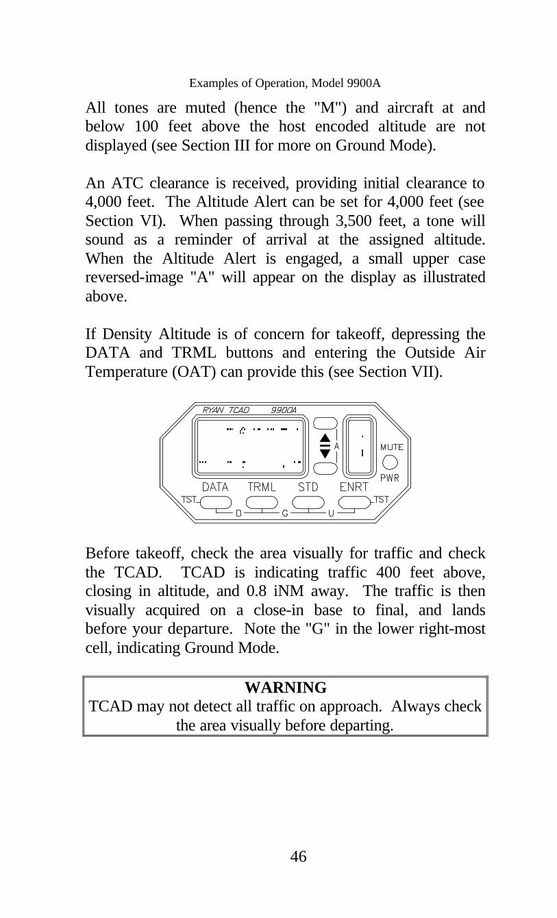
All tones are muted (hence the "M") and aircraft at and below 100 feet above the host encoded altitude are not displayed (see Section III for more on Ground Mode). An ATC clearance is received, providing initial clearance to 4,000 feet. The Altitude Alert can be set for 4,000 feet (see Section VI). When passing through 3,500 feet, a tone will sound as a reminder of arrival at the assigned altitude. When the Altitude Alert is engaged, a small upper case reversed-image "A" will appear on the display as illustrated above. If Density Altitude is of concern for takeoff, depressing the DATA and TRML buttons and entering the Outside Air Temperature (OAT) can provide this (see Section VII).
Before takeoff, check the area visually for traffic and check the TCAD. TCAD is indicating traffic 400 feet above, closing in altitude, and 0.8 iNM away. The traffic is then visually acquired on a close-in base to final, and lands before your departure. Note the "G" in the lower right-most cell, indicating Ground Mode.
WARNING TCAD may not detect all traffic on approach. Always check
the area visually before departing.

Examples of Operation, Model 9900A
47
After climbing more than 200 feet, the "M" disappears, indicating that the alert tones are enabled. The mode symbol changes to "Dp", indicating departure transition, until the aircraft climbs above the programmed base of the Enroute Mode (see Section III). Note the reversed-image "A" remains, indicating that the Altitude Alert is set.
Passing through 2,900 feet, “traffic” sounds. The traffic shows 500 feet above the host aircraft, closing in altitude, 1.0 iNM. The iNM is getting smaller, indicating closure in range. The traffic is acquired visually, descending.
TCAD shows the closest point of approach, 200 feet below and 0.5 iNM. Altitude separation and range then increase.

Examples of Operation, Model 9900A
48
During climb out, the TCAD automatically transitions to Enroute Mode. At 3,500 feet, the Altitude Alert sounds indicating the aircraft is nearing 4,000 feet. At 4,000 feet the reversed-image "A" changes to a normal "A".
Traffic is acquired, 1000 feet above, and 2.5 iNM.
Pressing the DATA button shows the traffic to be VFR at 5,000 feet MSL.

Examples of Operation, Model 9900A
49
The traffic is now climbing, and will shortly leave the monitored area.
Cleared out of 4,000 feet for Flight Level 210. Reset the Altitude Alert to FL 210.
Passing through 10,000 feet, the alert sounds. TCAD shows traffic 1,400 feet below, closing in altitude at 2.8 iNM. Since the threat is closing in altitude, it is also climbing. Continue to monitor. You may want to visually acquire the traffic (see Scanning, Section IX, and Appendix 2).

Examples of Operation, Model 9900A
50
The altitude separation is getting smaller, but the iNM is staying about the same. The traffic is probably flying a parallel course.
Pressing the DATA button reveals the target has a Mode A/C transponder, but no squawk has been acquired. ATC verifies the traffic climbing to 9000 feet.
Leveling at FL 210, the Unrestricted Mode is selected (see Section III). Traffic is displayed 8,000 feet above and 5.3 iNM.

Examples of Operation, Model 9900A
51
DATA reveals the traffic as N864UA, likely airline traffic. Later, the Approach Mode is set in anticipation of descent and landing (See Section III).
Descending now, TCAD automatically enters the Approach Mode (as shown by the “Ap”). If a high-rate descent is made, the Dynamic Shield would expand to monitor for traffic below the set shield. The alert sounds, TCAD shows traffic 1,000 feet above, closing and 2.0 iNM. The traffic is then visually acquired and later, ATC reports the traffic.
The traffic is now 500 feet above and 1.5 iNM. A second threat has entered the monitored area.

Examples of Operation, Model 9900A
52
Pressing the s button, the secondary threat, shows 1,100 feet above and 2.6 iNM. Note the airplane symbol is reversed (see Section IV and Section IX). After a few seconds, only the closer of the two threats is displayed.
The traffic eventually passes out of the shield. On short final, TCAD automatically transitions to the Ground Mode.
53
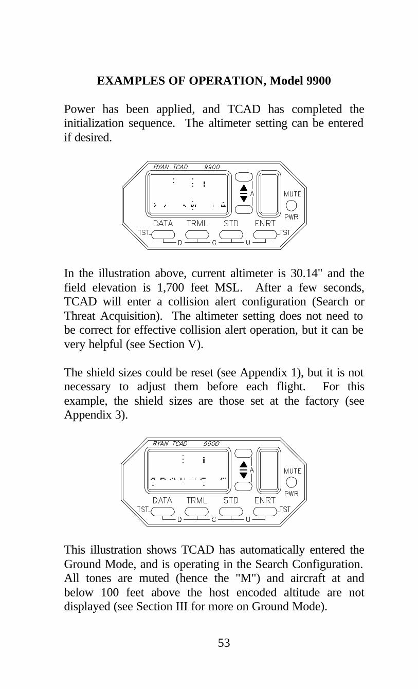
EXAMPLES OF OPERATION, Model 9900 Power has been applied, and TCAD has completed the initialization sequence. The altimeter setting can be entered if desired.
In the illustration above, current altimeter is 30.14" and the field elevation is 1,700 feet MSL. After a few seconds, TCAD will enter a collision alert configuration (Search or Threat Acquisition). The altimeter setting does not need to be correct for effective collision alert operation, but it can be very helpful (see Section V). The shield sizes could be reset (see Appendix 1), but it is not necessary to adjust them before each flight. For this example, the shield sizes are those set at the factory (see Appendix 3).
This illustration shows TCAD has automatically entered the Ground Mode, and is operating in the Search Configuration. All tones are muted (hence the "M") and aircraft at and below 100 feet above the host encoded altitude are not displayed (see Section III for more on Ground Mode).

Examples of Operation, Model 9900
54
An ATC clearance is received, providing initial clearance to 4,000 feet. The Altitude Alert can be set for 4,000 feet (see Section VI). When passing through 3,500 feet, a tone will sound as a reminder of arrival at the assigned altitude. When the Altitude Alert is engaged, a small upper case reversed-image "A" will appear on the display as illustrated above. If Density Altitude is of concern for takeoff, depressing the DATA and TRML buttons and entering the Outside Air Temperature (OAT) can provide this (see Section VII).
Before takeoff, check the area visually for traffic and check the TCAD. TCAD is indicating traffic 400 feet above, closing in altitude, and 0.8 iNM away. The traffic is then visually acquired on a close-in base to final, and lands before your departure. Note the "G" in the lower right-most cell, indicating Ground Mode.
WARNING TCAD may not detect all traffic on approach. Always check
the area visually before departing.

Examples of Operation, Model 9900
55
After climbing more than 200 feet, the "M" disappears, indicating that the alert tones are enabled. “Dp” indicates departure transition. As the aircraft climbs, TCAD will automatically change to Enroute (see Section III). Note the reversed-image "A" remains, indicating that the Altitude Alert is set.
Passing through 2,900 feet, a tone sounds. The traffic shows 500 feet above the host aircraft, closing in altitude, 1.0 iNM. The iNM is getting smaller, indicating closure in range.
The traffic is acquired visually, crossing from left to right, descending. TCAD shows the closest point of approach, 200 feet below and 0.5 iNM. During climb out, the TCAD automatically transitions to Enroute Mode.

Examples of Operation, Model 9900
56
After the traffic passes, altitude separation and range increase.
At 3,500 feet, the Altitude Alert sounds indicating the aircraft is nearing 4,000 feet. At 4,000 feet the reversed-image "A" changes to a normal "A".
Traffic is acquired 1000 feet above and 2.5 iNM.

Examples of Operation, Model 9900
57
Pressing the DATA button shows the traffic 5,000 MSL. ATC identifies the traffic at 5000 feet.
The traffic is now climbing, and will shortly leave the monitored area.
Later in the flight, the alert sounds. TCAD shows traffic 1,400 feet below, closing in altitude at 2.8 iNM. Since the threat is closing in altitude, it is climbing. Continue to monitor. You may want to visually acquire the traffic (see Scanning, Section IX, and Appendix 2).

Examples of Operation, Model 9900
58
The altitude separation is getting smaller, but the iNM is staying about the same. The traffic is probably flying a parallel course. Later, the Approach Mode is set in anticipation of descent and landing (See Section III).
Descending now, TCAD automatically transitions to the Approach Mode (as shown by the “Ap” in the lower right of the display). The alert sounds, and TCAD shows traffic 1,000 feet above, closing and 2.0 iNM. The traffic is then visually acquired. A short time later, ATC reports the traffic.
The traffic is now 500 feet above and 1.5 iNM. A second threat has entered the monitored area.
Examples of Operation, Model 9900
59
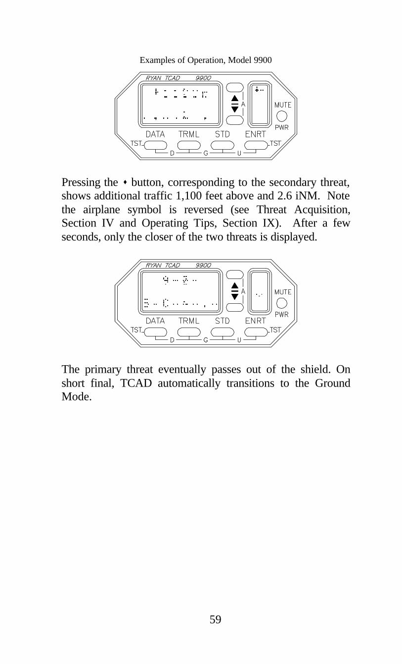
Pressing the s button, corresponding to the secondary threat, shows additional traffic 1,100 feet above and 2.6 iNM. Note the airplane symbol is reversed (see Threat Acquisition, Section IV and Operating Tips, Section IX). After a few seconds, only the closer of the two threats is displayed.
The primary threat eventually passes out of the shield. On short final, TCAD automatically transitions to the Ground Mode.

60
This page intentionally left blank

61
SECTION IX OPERATING TIPS ____________________________________ ____________________________________ SCANNING To optimize use of the data provided by TCAD, the pilot should consider where the greatest potential for collision is, and how to best find the traffic. If the threat aircraft is well above or below your airplane, no action may be necessary on your part to avoid the threat and the traffic can be located if desired. CAUTION: Because of encoder variations, any threat within 300 feet of your altitude should be considered at your altitude. For threats detected at or near your altitude, first scan ahead of the aircraft, then expand the scan to the left and right. By maintaining adequate vertical separation, traffic can always be avoided. Most flight hours are flown by Mode C equipped aircraft. Replies received from non-Mode C aircraft will cause NO ALT to be displayed on TCAD, with the iNM. The pilot must analyze this traffic without knowing the altitude difference. Since TCAD range indications are based from your aircraft, some altitude information is available from non-mode C traffic. For example, non-mode C traffic 6,000 feet directly above your aircraft will likely never show closer than 1 iNM. Appendix 3 contains excerpts from AC 90-48C, Pilot's Role in Collision Avoidance, which provides additional tips on visual scanning.

62
"NO ALT" REPLIES Many aircraft have encoding altimeters that require warm-up time. The replies received from warming-up encoders do not contain altitude data. TCAD will indicate NO ALT from these aircraft, until their encoder is provides altitude data. These replies often come from aircraft interrogated while on the ground. Thus, TCAD may display NO ALT even in locations where altitude reporting is required. Occasionally a NO ALT indication can be generated from sources other than non-Mode C traffic. These replies come from operations unrelated to civilian air traffic control, and are more likely to occur along the coasts. There is no difference between these replies and non-Mode C replies and the data is treated as traffic. TCAD priority computations weight nearby Mode C traffic above the non-Mode C, so altitude-equipped traffic will be prioritized and displayed appropriately. Good management of shield size will minimize extraneous indications. RANGE CONSIDERATIONS Range is displayed in indicated Nautical Miles (iNM). Actual range is equal to iNM when the threat aircraft’s transponder output power is normal, and the signal is not shadowed by the airframe. Transponders used aboard general aviation aircraft typically provide close agreement between iNM and actual range. Higher speed aircraft, such as airliners, often transmit stronger transponder signals, usually two times the power of general aviation transponders. In this case the actual range will be about 40% greater than the displayed iNM, thus offering greater margins for these high-speed aircraft. For example, an airliner showing 3.0 iNM may actually be four miles or more away. An airliner showing 0.7 iNM is likely to be a mile away.

63
The location of the transponder antenna on the threat aircraft can affect TCAD performance. A shadowed signal will reduce the ability of TCAD to detect the traffic. Antenna patterns can also cause an increase in the radiated signals, making the iNM closer than actual distance. These anomalies are more pronounced beyond three iNM. (see Appendix 2, TCAD Limits). While iNM is influenced by transponder power output and airframe shadowing, the trend in iNM is essentially independent of these factors. The received signal energy will increase or decrease as the range from the traffic changes. Therefore the trend in iNM is important for effective collision alert (also see Scalloping in this section). The display of indicated Nautical Miles increments in 0.1 iNM intervals from 0.0 to 6.0 iNM. DISPLAY PRIORITY When more than one threat is available for display, TCAD assigns a priority to each threat. There is greater emphasis on threats at or near the host altitude. The primary threat displayed by TCAD is the threat having highest priority. Note: Altitude separation and proximity determine the priority of a threat. As each threat changes position, a secondary threat can become the primary threat.

64
DYNAMIC SHIELD (Models 9900A and 9900B) If the host aircraft climbs (or descends) more than 800 feet per minute, traffic 500 feet above (or below) the boundary of the selected shield will be displayed. Alert tones will not be issued until the TCAD detects shield penetration. This gives the pilot awareness of traffic beyond the selected shield that may become a threat. HIGH DENSITY OPERATION For best operation in high-density areas, make the Air Traffic Shield as small as practicable. By reducing the shield size, detected signals will represent imminent potential threats, not extraneous information. DATA The DATA button displays the MSL altitude (or Flight Level) of traffic. The Mode A squawk will also be shown, if available. The squawk helps to determine if the traffic is VFR, IFR, or VFR handled by ATC. To get the correct MSL altitude, the altimeter setting in the TCAD must be correct. Transponder code and altitude are available for primary, secondary, and third level threats. The Mode A code of the threat aircraft is not always available because of matching and interrogator limitations. This does not compromise the collision-alert function or indicate degraded operation. If the squawk is not available, TCAD displays “Mode A/C”, or “Mode A” as appropriate. U.S. registered Mode S traffic will display the N-number instead of the Mode A code. This is helpful when the traffic is also on the ATC frequency. The N-number makes it possible to anticipate a potentially conflicting vector.

65
MULTIPLE THREATS When a second target is detected within the selected Air Traffic Shield, a small aircraft symbol is shown. Another aircraft symbol is displayed when a third threat is detected. Generally the shield size should be reduced when three threats are detected within the monitored area.
The additional threats can be displayed by pressing the s or t button next to the aircraft symbol. The secondary threat is displayed when the s button is depressed. A third threat is displayed when the t button is depressed. An indication is provided to confirm which threat is displayed. When the appropriate button is pressed, the corresponding aircraft symbol illuminates to provide a visual indication (see the illustration above). A flashing aircraft symbol indicates the second or third threat is nearby and opposite in altitude (see Multiple Threats, Section IV).

66
MONITORING TRAFFIC Even when traffic is visually acquired, it may be difficult to maintain visual contact. Monitor TCAD for unexpected changes in altitude or iNM. SCALLOPING Antenna transmission and reception patterns exhibit a property that can be helpful in traffic awareness. The effect, called scalloping or lobing, is non-uniformity in signal strength around antennas, and can be used as an indication that the traffic could be on a collision course. Traffic on a collision course does not move laterally, so the antenna pattern does not cross lobes. Received signals normally will be stable and the iNM indication will step down smoothly. When traffic crosses lobes, fluctuation in the signal level will cause variability in the iNM display. Thus, a smooth decrease in iNM should generally be of greater concern than a fluctuating iNM display. Note: Aircraft detected inside the shield should never be ignored. The traffic may become a threat by changing course or altitude unexpectedly.

67
CONSIDERATIONS FOR SETTING SHIELD RADIUS Shield radius settings should be optimized (see Setup, Appendix 1). If the shield radius is set too high, extraneous alerts will be sounded from aircraft that are no threat. If set to an excessively small value, warning time is compromised. Use minimum values that provide adequate warning time. Studies have shown that, given an alert, a minimum of ten seconds warning time is practical. During the ten second warning, the pilot first interprets the displayed data to determine the altitude difference. An immediate reaction is necessary only if this difference is zero or small. Two aircraft converging at 540 knots will cover a distance of 1.5 NM in 10 seconds. Below 10,000 feet, it is unlikely that the converging speed between two aircraft would exceed this value. With the radius set at 1.5 iNM, the warning time for threat aircraft would likely exceed ten seconds. A radius of 1.5 iNM would generally be adequate for standard conditions, with a larger radius for Enroute and a smaller radius for Terminal Mode. The shield size is the pilot’s decision. CONSIDERATIONS FOR SETTING SHIELD HEIGHT Two aircraft converging in altitude at 2400 feet per minute will change altitude by 400 feet in ten seconds. A ±1,000-foot shield height can be used in standard conditions. In terminal areas where climb and descent rates are usually slower, the limits could be narrowed, and then expanded for enroute flight. When the shield around the host aircraft is thin, extraneous alerts can be practically eliminated, while maintaining good shielding against threats.

68
PROFILE DISPLAY By presenting traffic data in profile, emphasizing altitude separation, the complexity of traffic alert is greatly simplified. Any traffic not close in altitude can be disregarded, and multiple threats can be simply recognized and resolved (see Multiple Threats, Section IV). DUAL DISPLAY OPERATION If a second display is installed, common functions such as altimeter setting and mode selection can be made from one display and will be communicated to the other display. TCAD will operate in only one common mode (i.e. TRML, STD, or ENRT). Independent functions such as DATA & MSL altitude and second threats can be accessed independently. ALERT TONES TCAD is designed to keep the number of audible alerts to a minimum. An alert tone is issued only once for traffic outside the Imminent Alert airspace (see Section IV). This means traffic that momentarily goes beyond the shield limits and then returns will not cause additional warnings. BEARING (Model 9900B) The TCAD bearing indicator is designed to give the pilot a general direction to look for the traffic. Antenna placement, shadowing and rate of angular change can cause slight discrepancies between the observed angle and the angle measured by TCAD.

69
SECTION X BUILT-IN TEST & FAULT DISPLAYS ____________________________________ ____________________________________ A TCAD built-in test function and Performance Monitor is provided. Electronic detection of faults is limited. An observant pilot is the best and most effective monitor of the equipment. Initiate the test by pressing the DATA and ENRT buttons simultaneously. The following is displayed: 1. Testing Remote. 2. The Alert light illuminates (if installed) and the word
“testing” is generated in the audio system. 3. SYS CHK: OK 4. COM LINK 100% (should be 95% or greater) 5. Testing Display. 6. The display will then show the software versions. If there is a fault indication, do not use TCAD data. CAUTION: TCAD does not display traffic information during the Built-in Test procedure. A cursor on the display confirms continued operation of the equipment. Two dots in the cell immediately to the left of the mode cell alternately illuminate, indicating continued operation. If the dots do not alternate, the equipment is not operating. “Link Failure" indicates a disrupted communications link between the processor and display. Error codes helpful in the troubleshooting of system problems can be displayed. If an unusual series of letters and numbers are shown, record the information to assist maintenance.

70
This page intentionally left blank.
71
APPENDIX 1 SETUP ____________________________________ ____________________________________ PROGRAMMING The user can set several parameters in the TCAD. These parameters are kept in memory, and do not have to be adjusted until desired. This allows flexibility for the pilot, yet requires minimum effort before flight. To engage a programming function, the appropriate button is pressed twice. The current setting will be displayed. The up and down buttons can be used to adjust the displayed parameter. To select the next parameter, the appropriate button is pressed again. When each parameter has been considered, TCAD returns to collision alert operation. In all cases, if no button is pressed for about 8 seconds when in a programming mode, TCAD will step to the next selection until it returns to collision alert operation. SETTING THE SHIELD SIZE Depress the selected button (TRML, STD, or ENRT) twice. The shield height in 100-foot increments will be displayed. To change the height, press the s or t buttons. Depress the selected button again for shield radius adjustment. Depress the mode button once more to return TCAD to normal operation. Note: For considerations in setting shield size, see Section IX, Operating Tips.
72
TONE OPTIONS To select default tone options, depress the Mute button twice. The Tone Volume can be adjusted using the up or down buttons. Depress Mute again to adjust Mute Time Duration. Depressing the Mute button again allows enabling or disabling of voice traffic alerts. A final press of Mute will return the TCAD to collision alert operation. If no button is pressed for 8 seconds, TCAD will automatically step to the next selection until it returns to collision alert operation. The sequence for tone related set up is as follows: Press Mute twice: Volume Set Press Mute again: Mute Duration Press Mute again: Voice Enabled or Disabled Press Mute again: Returns to operation TCAD issues an alert tone for traffic outside the imminent alert airspace only once. This means traffic that momentarily goes beyond the shield limits and then returns will not create an annoyance.

73
APPENDIX 2 LIMITS ____________________________________ ____________________________________ The TCAD only displays intruders equipped with operative transponders. TCAD provides no indication of traffic conflicts with aircraft without transponders, or where the threat aircraft is outside a Secondary Surveillance Radar (SSR) environment. AIRFRAME SHADOWING Microwave energy can be obstructed by the airframes of both the host and threat aircraft. A shadowing occurs when the signals must pass around metal structures. TCAD is designed to operate optimally when the host TCAD antenna and the threat transponder antenna are in line of sight. With the TCAD antenna top and bottom mounted, and with transponder antennas bottom mounted, the optimal condition generally exists when threats are above, to approximately 15 degrees below the host aircraft. When the threat is further below the host aircraft, or during turns, signals can be attenuated, causing display of greater than actual iNM. Transponder antenna placement on the threat aircraft and flight maneuvers also have an effect. Whenever a detected threat is below the aircraft, consider airframe shadowing when analyzing the data. For a threat to remain in the shadowed region, a lengthy and parallel track between host and threat is necessary, such as final approach to a runway when the threat is below your aircraft. Note: Airframe shadowing does not affect the accuracy of altitude separation information.

74
SIGNAL REFLECTIONS Transponder signals can be reflected by nearby structures. This can result in unreliable altitude and iNM indications, especially near hangars or buildings. This condition occurs primarily when the host aircraft is on the ground, since the top mounted TCAD antenna is less exposed to reflections while in flight. OVERLAPPED REPLIES When two aircraft are interrogated at the same instant, the replies received by TCAD can be mixed, degrading the ability to decode the replies. This is more likely to occur in higher density areas, when both aircraft are illuminated at the same moment by the same radar. By using degarbling techniques, the processor can often provide data on the closest threat. In some instances, both aircraft will be decoded, and in other instances, accurate decoding is impossible. This means the traffic may not be displayed on TCAD at all. By keeping the shield size small in high-density areas, the potential for garbled replies is minimized. CAUTION: Federal Regulations state that "When an ATC clearance has been obtained, no pilot in command may deviate from that clearance, except in an emergency, unless he obtains an amended clearance." Traffic information provided by the Ryan TCAD does NOT relieve the pilot in command of this responsibility.

75
APPENDIX 3 EXCERPTS ____________________________________ ____________________________________ Excerpts from AC 90-48C; Pilot's Role in Collision Avoidance. 1. PURPOSE. This advisory circular is issued for the purpose of alerting all pilots to the potential hazards of midair collision and near midair collision, and to emphasize those basic problem areas related to the human causal factors where improvements in pilot education, operating practices, procedures, and improved scanning techniques are needed to reduce midair conflicts. • • • • 4. ACTION. The following areas warrant special attention and continuing action on the part of all pilots to avoid the possibility of becoming involved in a midair conflict. a. "See and Avoid" Concept. (1) The flight rules prescribed in Part 91 of the Federal Aviation Regulations (FAR) set forth the concept of "See and Avoid." This concept requires that vigilance shall be maintained at all times, by each person operating an aircraft, regardless of whether the operation is conducted under Instrument Flight Rules (IFR) or Visual Flight Rules (VFR). (2) Pilots should also keep in mind their responsibility for continuously

76
maintaining a vigilant lookout regard-less of the type of aircraft being flown. Remember that most MAC accidents and reported NMAC incidents occurred during good VFR weather conditions and during the hours of daylight. b. Visual Scanning. (1) Pilots should remain constantly alert to all traffic movement within their field of vision, as well as periodically scanning the entire visual field outside of their aircraft to ensure detection of conflicting traffic. Remember that the performance capabilities of many aircraft, in both speed and rates of climb/descent, result in high closure rates limiting the time available for detection, decision, and evasive action. (2) The probability of spotting a potential collision threat increases with the time spent looking outside, but certain techniques may be used to increase the effectiveness of the scan time. The human eyes tend to focus somewhere, even in a featureless sky. In order to be most effective, the pilot should shift glances and refocus at intervals. Most pilots do this in the process of scanning the instrument panel, but it is also important to focus outside to set up the visual system for effective target acquisition. (3) Pilots should also realize that

77
their eyes may require several seconds to refocus when switching views between items in the cockpit and distant objects. Proper scanning requires the constant sharing of attention with other piloting tasks, thus it is easily degraded by such psychophysiological conditions such as fatigue, boredom, illness, anxiety, or preoccupation. (4) Effective scanning is accomplished with a series of short, regularly-spaced eye movements that bring successive areas of the sky into the central visual field. Each movement should not exceed 10 degrees, and each area should be observed for at least 1 second to enable detection. Although horizontal back-and-forth eye movements seem preferred by most pilots, each pilot should develop a scanning pattern that is most comfortable and then adhere to it to assure optimum scanning. (5) Peripheral vision can be most useful in spotting collision threats from other aircraft. Each time a scan is stopped and the eyes are refocused, the peripheral vision takes on more importance because it is through this element that movement is detected. Apparent movement is almost always the first perception of a collision threat, and probably the most important, because it is the discovery of a threat that triggers the events leading to proper evasive action. It is essential to remember, however, that if another
78
aircraft appears to have no relative motion, it is likely to be on a collision course with you. If the other aircraft shows no lateral or vertical motion, but is increasing in size, take immediate evasive action. (6) Visual search at night depends almost entirely on peripheral vision. In order to perceive a very dim lighted object in a certain direction, the pilot should not look directly at the object, but scan the area adjacent to it. Short stops, of a few seconds, in each scan will help to detect the light and its movement. (7) Lack of brightness and color contrast in daytime and conflicting ground lights at night increase the difficulty of detecting other aircraft. (8) Pilots are reminded of the requirement to move one's head in order to search around the physical obstructions, such as door and window posts. The doorpost can cover a considerable amount of sky, but a small head movement may uncover an area which might be concealing a threat. c. Clearing Procedures. (1) Pilots should: (i) Prior to taxiing onto a runway or landing area for takeoff, scan the approach areas for possible landing traffic by maneuvering the aircraft to provide a clear view of such areas. It

79
is important that this be accomplished even though a taxi or takeoff clearance has been received. (ii) During climbs and descents in flight conditions which permit visual detection of other traffic, execute gentle banks left and right at a frequency which permits continuous visual scanning of the airspace about them. (iii) Execute appropriate clearing procedures before all turns, abnormal maneuvers, or acrobatics. d. Airspace, Flight Rules, and Operational Environment. (1) Pilots should be aware of the type of airspace in which they intend to operate in order to comply with the flight rules applicable to that airspace. Aeronautical information concerning the National Airspace System is disseminated by three methods: aeronautical charts (primary); the Airman's Information Manual (AIM); and the Notices to Airmen (NOTAM) system. The general operating and flight rules governing the operation of aircraft within the United States are contained in Part 91 of the FAR. (2) Pilots should: (i) Use currently effective aeronautical charts for the route or area in which they intend to operate. (ii) Note and understand the aeronautical legend and chart symbols

80
related to airspace information depicted on aeronautical charts. (iii) Develop a working knowledge of the various airspace segments, including the vertical and horizontal boundaries. (iv) Develop a working knowledge of the specific flight rules (FAR 91) governing operation of aircraft within the various airspace segments. (v) Use the AIM. The Basic Flight Information and ATC procedures describe the airspace segments and the basic pilot responsibilities for operating in such airspace. (vi) Contact the nearest FAA Flight Service Station for any pertinent NOTAMS pertaining to their area of operation. (3) Pilots should also be familiar with, and exercise caution, in those operational environments where they may expect to find a high volume of traffic or special types of aircraft operation. These areas include Terminal Radar Service Areas (TRSA's), airport traffic patterns, particularly at airports without a control tower; airport traffic areas (below 3,000 feet above the surface within five statute miles of an airport with an operating control tower); terminal control areas; control zones, including any extensions; Federal airways; vicinity of VOR's; restricted areas; warning areas; alert areas; Military Operating Areas (MOA); intensive student jet training areas;

81
military low-level high-speed training routes; instrument approach areas; and areas of high density jet arrival/ departure routings, especially in the vicinity of major terminals and military bases. e. Use of Communications Equipment and Air Traffic Advisory Services. (1) One of the major factors contributing to the likelihood of NMAC incidents in terminal areas that have an operating air traffic control (ATC) system has been the mix of known arriving and departing aircraft with unknown traffic. The known aircraft are generally in radio contact with the controlling facility (local, approach, or departure control) and the other aircraft are neither in two-way radio contact nor identified by ATC at the time of the NMAC. This precludes ATC from issuing traffic advisory information to either aircraft. (2) Although pilots should adhere to the necessary communications requirements when operating VFR, they are also urged to take advantage of the air traffic advisory services available to VFR aircraft. (3) Pilots should: (i) Use the AIM. (A) The basic AIM contains a section dealing with services

82
available to pilots, including information on VFR advisory services, radar traffic information services for VFR pilots, and recommended traffic advisory practices at nontower airports. (B) The airport/facility directory contains a list of all major airports showing the services available to pilots and the applicable communication frequencies. (ii) Develop a working knowledge of those facilities providing traffic advisory services and the area in which they give these services. (iii) Initiate radio contact with the appropriate terminal radar or nonradar facility when operating within the perimeters of the advertised service areas or within 15 miles of the facility when no service area is specified. (iv) When it is not practical to initiate radio contact for traffic information, at least monitor the appropriate facility communication frequency, particularly when operating in or through arrival/departure routes and instrument approach areas. (v) Remember that controller observation of aircraft in the terminal area is often limited by distance, depth perception, aircraft conspicuity, and other normal visual acuity problems. Limitations of radar (when available),

83
traffic volume, controller workload, unknown traffic etc., may prevent the controller from providing timely traffic advisory information. Traffic advisories are secondary to the controllers' primary duties (which are separating aircraft under their control and issuing safety advisories when aware of safety conflicts). Therefore, the pilot is responsible for seeing and avoiding other traffic. Traffic advisories should be requested and used when avail-able to assist the pilot to see and avoid other traffic by assisting, but not substituting in any way, the pilot's own visual scanning. It is important to remember that advisories which air traffic control may provide are not intended to lessen in any manner the pilot's obligation to properly scan to see and avoid traffic. f. Airport Traffic Patterns. (1) A significant number of midair collisions, as well as near midair collisions, have occurred within the traffic pattern environment. (2) Pilots should: (i) When operating at tower-controlled airports, maintain two-way radio contact with the tower while within the airport traffic area. Make every effort to see and properly avoid any aircraft pointed out by the tower, or any other aircraft which may be in the area and unknown to the tower.
84
(ii) When entering a known traffic pattern at a nontower airport, keep a sharp lookout for other aircraft in the pattern. Enter the pattern in level flight and allow plenty of spacing to avoid overtaking or cutting any aircraft out of the pattern. (iii) When approaching an unfamiliar airport fly over or circle the airport at least 500 feet above traffic pattern altitude (usually at 2,000 feet or more above the surface) to observe the airport layout, any local traffic in the area, and the wind and traffic direction indicators. Never descend into the traffic pattern from directly above the airport. (iv) Be particularly alert before turning to the base leg, final approach course, and during the final approach to landing. At nontower airports, avoid entering the traffic pattern on the base leg or from a straight-in approach to the landing runway. (v) Compensate for blind spots due to aircraft design and flight attitude by moving your head or maneuvering the aircraft.

85
APPENDIX 4 ____________________________________ ____________________________________ SPECIFICATIONS General Weight: 7.6 pounds with mounting tray (3.4 Kg) Operating Voltage: 11 - 29 Volts DC Current Requirements: 1.2A @ 14 VDC 0.7A @ 28 VDC Display dimming: Automatic Shield Limits TRML: 200 FT to 1000 FT 0.5 iNM to 1.5 iNM STD: 500 FT to 1500 FT 1.0 iNM to 3.0 iNM ENRT: 1000 FT to 2000 FT 2.0 iNM to 5.0 iNM (6.0 for Mode S traffic) UNRESTRICTED MODE: 9900A and 9900B: ±10,000 FT and 6.0iNM Model 9900: ±5,000 FT and 3.0iNM

86
FACTORY SETTINGS TCAD is delivered with the following default settings: Audio Volume: Mid Range Mute Duration: 30 seconds Voice: Enabled ENRT Shield Size: ±2000 feet, 3.0 iNM STD Shield Size: ±1000 feet, 2.0 iNM TRML Shield Size: ±500 feet, 1.0 iNM Altimeter Setting: 29.92 inches Density Altitude Temperature: 59°F Altitude Alert: 5,000 feet

87
PARTS and SERVICE WARRANTY The Ryan TCAD is warranted against defects in materials and workmanship for 18 months from date of shipment to an authorized dealer, or one year from the date of original installation, whichever occurs first. The obligation of Ryan International Corporation is limited to the repair or replacement, at the option of Ryan International Corporation, of products, which prove to be defective during the warranty period. No other warranty is expressed or implied. Proper installation of the Ryan TCAD is the responsibility of the installing agency, and is not part of this warranty. Ryan International Corporation is not liable for consequential damages. Warranty protection is assured only when your Ryan TCAD is installed and serviced by an authorized dealer. CUSTOMER SUPPORT We appreciate the confidence you have placed in Ryan International Corporation, and in your avionics dealer. We trust that both the Ryan TCAD and your dealer have met your expectations. If you have questions or comments regarding the Ryan TCAD, please contact Customer Service at 800-877-0048. Serial Numbers and purchase information: Processor: ____________ Display: ____________ Date of Purchase: ____________ Dealer Name: ____________

88
DISCLAIMER The Ryan TCAD has been meticulously designed to provide warning of nearby traffic. As with any device, there are significant limitations. The TCAD can only detect signals if they are received. There are many impediments that prevent the signal from being received, including the lack of interrogation signals, and the relative signal patterns of the transmitting and receiving antennas. We must declare, in the strongest of terms, that TCAD is not foolproof, and will not warn of nearby traffic in every instance, nor will it, in itself, prevent collisions. We make no claim in this regard. The pilot must make the avoidance decisions. We do claim the TCAD is a very helpful device that can and has on many occasions saved the aircraft and occupants from disaster. Further, it aids in traffic awareness and traffic avoidance. The TCAD is an aid to the see and avoid process and does not replace the common sense and good judgment of the pilot. As a pilot, you must be relied upon for a certain level of competence and a high standard of knowledge about the airspace, aerodynamics, regulations, and the Ryan TCAD. This includes knowledge of the limitations as well as the capabilities of the TCAD. This equipment is designed to increase the pilot's awareness of nearby traffic. It will not detect every aircraft. It is not designed to replace the see and avoid responsibility of the pilot, or the ATC responsibility in the IFR environment. The information provided by TCAD is not intended to lessen in any manner the pilot's obligation to see and avoid traffic. The pilot in command of an aircraft is directly responsible for, and is the final authority as to, the operation of that aircraft.
89
MULTIFUNCTION DISPLAY INTERFACE SUPPLEMENT TO THE
PILOT'S HANDBOOK P/N 32-2303, Revision 0, July 6, 1998
Introduction This Pilot's Guide is a reference for the interface with the Ryan TCAD Model 9900B and other Multifunction Displays (MFD). It does not replace the Multifunction Display manufacturer's Operator's Manual or the Ryan TCAD Pilot's Handbook. Information regarding specific displays is found at the end of this supplement. Operator Controls & Basic Displays The Ryan TCAD Model 9900B Display serves as the TCAD controller and digital-profile traffic display. The MFD shows traffic information in a plan-view, graphical presentation. The MFD will initialize normally. When communication between the Multifunction Display and the TCAD is established, a message that your aircraft is specially equipped for traffic alert is displayed on the MFD. After initialization, proceed with operation of the Multifunction Display in a normal manner. TCAD data will be shown in a "thumbnail" abbreviated view on part of the display. The symbols for closing and parting traffic depicted on the MFD display are identical to those shown on the TCAD 9900B. The symbols and definitions are available at any time on a special help screen on the MFD.

90
The Air Traffic Shield The range and height of the TCAD-monitored area is controlled by the shield size selected on the TCAD. The range selected on the TCAD is the maximum range limit for traffic displayed on the MFD. Thumbnail Display: The solid circle is always one mile. The intermediate circle (if shown) represents three miles. The outermost circle shows the number that corresponds to the range for that circle. The shield range selected on TCAD determines the number on the outermost ring. TCAD “rounds” range to the next lowest whole number. For instance, if two iNM is selected then the outermost range ring will show 2. If 2.1, 2.2 or even 2.9 is selected, TCAD will round to 2inm. Traffic beyond two miles will be shown on the MFD out to the limit selected on TCAD. When only a dotted ring is shown, the range selected on the TCAD is less than 1 iNM, and the range ring corresponds to that selected range. The inner and middle range rings on the full-screen view are marked. The outer range ring corresponds to the range in the lower right corner of the display. Note that the scale on the display is compressed between three and six iNM, meaning the distance between the three mile and six mile ring is less than the distance between the one and three mile ring. This reduces clutter and dedicates more area for traffic close to your aircraft.

91
Threat Acquisition TCAD will respond normally to traffic acquisition, and the MFD will show the traffic as long as the bearing is available for the traffic (see limitations). As with other MFD functions, selecting the smallest TCAD range consistent with operations is best to minimize clutter on the display. Approximately six threats can be shown on the MFD. In the event of threat overlap, the higher-priority threat (the closer in altitude and range) is shown over the other threat until there is no longer any overlap. Help Displays The Help page on the MFD provides basic legend information to allow the operator to quickly interpret the traffic information on the MFD. Fault Displays If the MFD fails to detect the TCAD, or if the TCAD data received by the MFD is detected as invalid, TCAD ERROR will show on the thumbnail display. The large full-screen display will show "TCAD COMMUNICATION LOST". If the TCAD altitude information is invalid, the MFD will display TCAD ALT (on the thumbnail display) or TCAD ALTITUDE INVALID (on the full-screen display). Any display should also pass the "common sense" test. If the information displayed seems wrong it probably is and should be checked.
92
Appendix 1 Limitations TCAD uses transponder replies to track traffic. If the reply rate is low and your aircraft turns, there will be a momentary lag in the position change of the traffic. If your MFD supplies a heading correction, there should be little display lag due to turning your aircraft. Some jumpiness in the displayed threats can be expected due to reception angles and reflections. This is most evident at distances greater than three iNM or when your aircraft is on the ground. The number of threats displayed is limited, and TCAD monitors many more threats than can be shown on the display. When a threat of higher priority appears on the display, replacing one of lower priority, it appears that one of the threats jumps from one part of the display to another. This can be disconcerting, but is of no consequence. High traffic density areas, long ranges and maneuvers can create signal drop out, resulting in the display of two threats for one aircraft. The drop out is momentary, and the threats will quickly merge. They are not colliding. Occasionally TCAD will not show a bearing to a threat. The traffic will be displayed on the TCAD, and the normal audible and visual alerts will occur. Traffic without bearing is not displayed on the MFD. Appendix 2 Disclaimer The MFD is ancillary to the TCAD display. Traffic information, especially regarding the altitude separation, is available immediately by viewing the TCAD display.

93
Appendix 3 (Reserved)

94
Appendix 4 Interface with Ryan TCAD 9900B and the Argus Series Moving Map Displays. There are two ways to access secondary functions on the ARGUS. INFOrmation can be accessed by pressing [ENR] and [AUX], or with a remote switch or button on the panel or the yoke. Similarly, SELect can be accessed by pressing AUX and DEP, or by a remote switch or button. When INFO or SEL are referred to in this section, "press the button" is used but in fact any of the above methods can be used. The ARGUS will scroll through the normal self-test and limitations display. When the message "push key to continue" is shown, press any key. When communication between the Argus and the TCAD is established, a message that your aircraft is specially equipped for traffic alert is displayed. Press any key again. Proceed with operation of the ARGUS in a normal manner. If MP+PL was selected in the Amend mode (see Amend section in this guide) TCAD data will be shown in a "thumbnail", abbreviated view in the lower left corner of the display (see Figure 1). The symbols shown on the display are similar to those shown on the TCAD and are defined in Figure 3. Symbol definitions are available on a special help page on the ARGUS. The thumbnail display is not shown in the ARRival Mode.

95
Figure 1 Thumbnail Traffic Display

96
Figure 2 Full-screen Traffic Display When the INFORmation Mode is selected the TCAD thumbnail view will expand to a full-screen view (see Figure 2). The full-screen view shows the altitude separation next to each threat. When the TCAD is displayed on the full-screen, pressing the SELect button will cause an individual threat to be tagged with a rectangle containing the MSL altitude (or Flight Level) of that threat (this is called the Traffic Selection function). The N-number, squawk or transponder type will be shown in the bottom center of the screen. Each additional press of the SELect button will sequence the tag to the next highest priority traffic (as defined by the TCAD) until all the threats have been shown. To exit the TCAD SELect mode, press the SELect button to step through each threat until the last threat is displayed. Hold the INFOrmation button for more than one second to return the ARGUS to its previous mode and the TCAD to the thumbnail display. As with the ARGUS, selecting the smallest TCAD range consistent with operations is best to minimize clutter on the display. Help Function & Fault Displays Press the INFOrmation button when showing full-screen traffic information to access the TCAD Help function. If the ARGUS fails to detect the TCAD, TCAD ERROR will be shown on the thumbnail display. The large full-screen display will show "TCAD COMMUNICATION LOST". Failure of the altitude input to TCAD will cause TCAD ALT and TCAD ALTITUDE INVALID to be displayed on the Argus
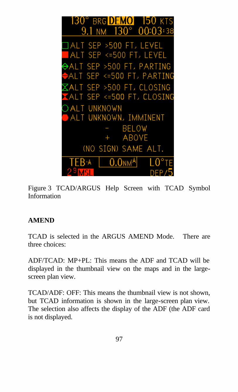
97
Figure 3 TCAD/ARGUS Help Screen with TCAD Symbol Information AMEND TCAD is selected in the ARGUS AMEND Mode. There are three choices: ADF/TCAD: MP+PL: This means the ADF and TCAD will be displayed in the thumbnail view on the maps and in the large-screen plan view. TCAD/ADF: OFF: This means the thumbnail view is not shown, but TCAD information is shown in the large-screen plan view. The selection also affects the display of the ADF (the ADF card is not displayed.

98
ADF Mode: This means the thumbnail view is not shown, but TCAD information is shown in the large-screen plan view. The selection also affects the display of the ADF (the ADF card is shown full time). The same amend page will also enable the TCAD help page to be displayed. TCAD help can be selected, Y or N. If Y is selected, then the help page is available when the INFOrmation button is pressed when viewing the large-screen TCAD display on the ARGUS. Exit AMEND Mode normally. Table of Buttons and Functions Understanding of the interface with TCAD with ARGUS can be enhanced with an understanding of the buttons and functions: All TCAD parameters such as shield height and shield radius and TCAD Mode selection are controlled by the TCAD display. Function Press Result Amend, to select the TCAD display options on ARGUS
[AUX] three times, then select AMEND
To choose the TCAD thumbnail view on all map modes except Arrival, select MP+PL. To enable the large-screen Plan view only, select TCAD + ADF:off or ADF Mode. Also enable the help page, Y or N.
Show the TCAD thumbnail
No button press is necessary.
The thumbnail display (shown in Figure 2) is

99
display. available in all modes except ARRival. See Figure 3 for symbol information.
Function Press Result To go from the thumbnail TCAD display to the full-screen TCAD display
Press INFO Expanded TCAD information is displayed. See Figure 2.
To go from the full-screen TCAD display back to the thumbnail display.
Hold INFO for more than one second.
The thumbnail display (shown in Figure 2) is available in all modes except ARRival. See Figure 3 for TCAD symbol information.
To access the Traffic Selection function; to get MSL altitude & Squawk/N-number of traffic
Press SEL when in the full-screen TCAD display.
Shows the MSL of the selected traffic and the transponder type, N-number or squawk of the traffic is shown at the bottom of the display. Press the SEL button to select additional traffic.
To get out of the Traffic Selection function
Press the SEL button until all threats have been selected, then once more for the full-screen TCAD display.
To access the help screen, for TCAD symbol definitions
Press INFO when in the full-screen view
TCAD will display TCAD symbol definitions. See Figure 3.

100
To go from the help screen back to the thumbnail view
Hold INFO button down for more than one second.
Thumbnail view is shown
Disclaimer The ARGUS display is supplemental to the TCAD display. Traffic information about the traffic, particularly regarding the altitude separation, is available immediately by viewing the TCAD display.
-end-
End of Multifunction Display Interface Supplement to the Pilot's Handbook

101
Index
A "A" See Altitude Alert "Ap" transition symbol 19 AC 90-48C excerpts 75 Advisory Circular 75 Airframe Shadowing 73 Air Traffic Shield 15 Alert Tones 78 Altimeter Setting 27 Altitude Alert 29 Altitude Alert Example 31 Altitude Deviation 29 Altitude Displays 28 Altitude Trend 4 Antenna 6 Approach Mode 18
B Barometric pressure setting 27 Basic Displays 11 Built-in Test 69 Buttons 8 Button Operation See Setup or Description of operator controls
C Components 6 Concept 2 Considerations for setting shield height 67 Considerations for setting shield radius 67 Controls, operator 8 Customer service number 87 Customer support 87
D "Dp" transition symbol 16 Data 24 Density Altitude 33 Description, Product 1 Description of operator controls 8 Disclaimer 88 Displays, basic 7 Displays, Flying with TCAD 35 Dual Display Operation 48

102
E ENRT See Enroute Mode ENRT symbol 10 Encoder accuracy 27 Enroute mode 15 Examples of Operation 35
F Factory Settings 86 Fault Displays 69 Features ii Flashing aircraft symbol 23 Flight Level display 28 Flying with TCAD 35
G "G" See Ground Mode Garbled Replies See Overlapped Replies Ground Mode 16
H High Density Operation 64 High Density Operation, code acquisition 64
I - J - K Imminent Alert 22 Indicated Nautical Miles 4 iNM increments 63 iNM trend 63
L Limits, Shield 85 Limits, TCAD 73 Link Failure 69 Lobing See Scalloping
M "M" See Mute MSL Altitude of Threat 27 Maximum Range See Shield limits Mode A Images 23 Mode indicator 10, 12, 13 Modes 15 Mode S traffic 24, 64 Monitoring traffic 66 Multifunction Display Interface Supplement 89 Multiple threats 23, 65 Mute 24 Mute Settings See Tone Options

103
N No Altitude threats 24, 62 Non-Mode C Traffic See No-Altitude threats N-number 24,64
O Operating Range See Shield limits Operating tips 61 Operating voltage 85 Operational examples 35 Operator controls 8 Overlapped replies 74
P - Q Parts 87 Parts and Service Warranty 87 Pilot's Role in Collision Avoidance 75 Power Requirements 85 Pressure setting 27 Priority, display 63 Product description 1 Profile Display 68 Programming 71
R Range Considerations 25, 62 Range determination 4 Range display increments 63 Range trend 5 Radius of shield See Setup Reflections 74 Reply overlap 74 Reply signals, use of 2
S STD See Standard Mode STD symbol 10 Scalloping 66 Scanning 61, 75 Search display 12 Secondary threat display 23, 65 Service 87 Settings, factory 86 Setting shield size 71 Setting tone options 72 Setup 71 Shadowing 73 Shield limits 85 Shield size considerations 67 Shield size setup 71

104
Signal reflections 74 Specifications 85 Squawk of threat See DATA Standard Mode 15 Symbols 10
T TCAD (Traffic and Collision Alert Device) 1 TCAD LIMITS 73 TRML See Terminal Mode TRML symbol 10 Target altitude See Altitude Alert Technology 3 Temperature See Density Altitude Terminal Mode 15 Test, Built-in 69 Third level threat display 23, 65 Threat acquisition 21 Threat acquisition display 13 Threat altitude 28 Threat code 24 Tips 61 Tone Options 72 Tones 11 Tone settings 72 Trend in iNM See Range Considerations
U "U" See Unrestricted Mode Unrestricted Mode 17 Update rate 25
V Visual acquisition 21 Visual scan 61, 75 Voltage 85
W - X - Y - Z Warranty 87 Weight 85

Copyright 1997, Ryan International Corporation Printed in USA
Related Documents


