INOM EXAMENSARBETE MASKINTEKNIK, GRUNDNIVÅ, 15 HP , STOCKHOLM SVERIGE 2021 Piezoelectric Guitar Tuner ALBIN BOESTAD FABIAN RUDBERG KTH SKOLAN FÖR INDUSTRIELL TEKNIK OCH MANAGEMENT

Welcome message from author
This document is posted to help you gain knowledge. Please leave a comment to let me know what you think about it! Share it to your friends and learn new things together.
Transcript

INOM EXAMENSARBETE MASKINTEKNIK,GRUNDNIVÅ, 15 HP
, STOCKHOLM SVERIGE 2021
Piezoelectric Guitar Tuner
ALBIN BOESTAD
FABIAN RUDBERG
KTHSKOLAN FÖR INDUSTRIELL TEKNIK OCH MANAGEMENT
Piezoelectric Guitar Tuner
Bachelor Thesis at ITM
ALBIN BOESTAD, FABIAN RUDBERG
Bachelor Thesis at ITMSupervisor:Nihad SubasicExaminer: Nihad Subasic
TRITA-ITM-EX 2021:24

Abstract
This bachelor thesis in Mechatronics account for theprocess of constructing an automatic guitar tuner by meansof a piezo-electric sensor, a stepper motor and Arduino-based control. The E4 - string on an acoustic guitar wasused as a proxy for tuning any other possible guitar string.The accuracy and tuning-speed of the construction was ex-amined through physical experimentation. Accuracy wasmeasured in terms of the average distance from a piezo-calibrated frequency value. The tuning-speed was appraisedby counting the number of times a guitar string had to beplucked before the motor stopped within an acceptable tun-ing interval. The automatic guitar tuner were able to reli-ably get the E4 - string in tune by plucking it once withinan interval of ±2 Hz and +3.8 cents and −5.1 cents fromthe theoretical value. The average error was −3.4 centsfrom the targeted value.
Keywords: Mechatronics Tuner Guitar Piezo Arduino
ReferatPiezoelektrisk Gitarrstämmare
I foljande kandidatexamensarbete kontrueras en automa-tisk gitarrstammare med hjalp av en piezosensor, en steg-motor och en Arduino-mikrokontroller. E4-strangen pa enakustisk gitarr anvandes som substitut for hur stamningsprocedurenskulle kunna fungera for vilken annan gitarrstrang som helst.Noggrannheten samt stamningshastigheten undersoktes ge-nom experiment. Genomsnittet av frekvensskillnaderna mel-lan de piezo-kalibrerade avlasningsvardena och E4-strangensvarden definierade mattet pa noggrannhet. Hastigheten pastrangstamningen beraknades i form av hur manga gangeren strang behovdes slas an innan strangen var inom ettgodkant intervall. Den automatiska gitarrstammaren visa-de sig palitiligt kunna stamma E4-strangen pa ett forsokinom ett noggrannhetsintervall pa ±2Hz fran det teoretis-ka vardet. Stammaren kunde stamma inom +3.4 cents och−5.1 cents samt var var i genomsnitt −3.4 cents i fran detteoretiska vardet.
Nyckelord: Mekatronik Stammare Guitar Piezo Arduino

Acknowledgements
We want to thank our supervisor Nihad Subasic for his unfaltering engagement dur-ing the course curriculum. Particularly for his immediate and straightforward criticduring the various challenges that came up during the project. We would also liketo thank course assistant Amir Avdic, who tirelessly and enthusiastically assistedus and other groups during the lab sessions.
Albin Boestad and Fabian Rudberg.KTH Royal Institute of Technology, Stockholm, May 2021

Contents
1 Introduction 11.1 Background . . . . . . . . . . . . . . . . . . . . . . . . . . . . . . . . 11.2 Purpose . . . . . . . . . . . . . . . . . . . . . . . . . . . . . . . . . . 11.3 Scope . . . . . . . . . . . . . . . . . . . . . . . . . . . . . . . . . . . 21.4 Method . . . . . . . . . . . . . . . . . . . . . . . . . . . . . . . . . . 2
1.4.1 Calibration . . . . . . . . . . . . . . . . . . . . . . . . . . . . 31.4.2 Sampling Frequency . . . . . . . . . . . . . . . . . . . . . . . 31.4.3 Piezo Reading Calibration . . . . . . . . . . . . . . . . . . . . 31.4.4 Acceptable Tuning Interval . . . . . . . . . . . . . . . . . . . 31.4.5 Kp Calibration . . . . . . . . . . . . . . . . . . . . . . . . . . 31.4.6 Accuracy . . . . . . . . . . . . . . . . . . . . . . . . . . . . . 41.4.7 Speed . . . . . . . . . . . . . . . . . . . . . . . . . . . . . . . 4
2 Theory 52.1 Musical intervals . . . . . . . . . . . . . . . . . . . . . . . . . . . . . 5
2.1.1 The musical alphabet . . . . . . . . . . . . . . . . . . . . . . 52.1.2 Octaves . . . . . . . . . . . . . . . . . . . . . . . . . . . . . . 62.1.3 Harmonics . . . . . . . . . . . . . . . . . . . . . . . . . . . . . 82.1.4 Tuning accuracy . . . . . . . . . . . . . . . . . . . . . . . . . 8
2.2 The Fast Fourier Transform . . . . . . . . . . . . . . . . . . . . . . . 82.3 Piezoelectric effect . . . . . . . . . . . . . . . . . . . . . . . . . . . . 92.4 Arduino Uno . . . . . . . . . . . . . . . . . . . . . . . . . . . . . . . 102.5 P-Controller . . . . . . . . . . . . . . . . . . . . . . . . . . . . . . . . 112.6 Stepper Motor . . . . . . . . . . . . . . . . . . . . . . . . . . . . . . 11
2.6.1 Stepper Motor Driver . . . . . . . . . . . . . . . . . . . . . . 122.6.2 H-bridge . . . . . . . . . . . . . . . . . . . . . . . . . . . . . . 13
3 Demonstration 143.1 Problem Formulation . . . . . . . . . . . . . . . . . . . . . . . . . . . 143.2 Hardware and Electronics . . . . . . . . . . . . . . . . . . . . . . . . 14
3.2.1 Piezoelement . . . . . . . . . . . . . . . . . . . . . . . . . . . 143.2.2 Arduino Uno . . . . . . . . . . . . . . . . . . . . . . . . . . . 153.2.3 Stepper Motor NEMA 17 . . . . . . . . . . . . . . . . . . . . 15

CONTENTS
3.2.4 Stepper motor driver Adafruit . . . . . . . . . . . . . . . . . 163.2.5 Connection . . . . . . . . . . . . . . . . . . . . . . . . . . . . 16
3.3 Software . . . . . . . . . . . . . . . . . . . . . . . . . . . . . . . . . . 173.4 Frequency detection . . . . . . . . . . . . . . . . . . . . . . . . . . . 17
4 Results 194.1 Calibration . . . . . . . . . . . . . . . . . . . . . . . . . . . . . . . . 19
4.1.1 Sampling Frequency . . . . . . . . . . . . . . . . . . . . . . . 194.1.2 Piezo Reading Calibration . . . . . . . . . . . . . . . . . . . . 194.1.3 Acceptable Tuning Interval . . . . . . . . . . . . . . . . . . . 204.1.4 Kp Calibration . . . . . . . . . . . . . . . . . . . . . . . . . . 20
4.2 Research findings . . . . . . . . . . . . . . . . . . . . . . . . . . . . . 204.2.1 Accuracy . . . . . . . . . . . . . . . . . . . . . . . . . . . . . 214.2.2 Speed . . . . . . . . . . . . . . . . . . . . . . . . . . . . . . . 24
5 Discussion and Conclusion 255.1 Discussion . . . . . . . . . . . . . . . . . . . . . . . . . . . . . . . . . 255.2 Conclusion . . . . . . . . . . . . . . . . . . . . . . . . . . . . . . . . 27
6 Future work 28
Bibliography 29
A Component list 32
B Glossary 34
C Parts of an acoustic guitar 35
D Stepper Motor Datasheet: Nema 17 36
E Blueprint Tuning Key Gripper 38
F Arduino Code 39
G Acumen Simluation 45
H Piezo Calibration Data 48
I Calibration data for the constant of proportional control, Kp 51I.1 Tuning from D#4 to E4. . . . . . . . . . . . . . . . . . . . . . . . . . 51I.2 Tuning from F4 to E4 . . . . . . . . . . . . . . . . . . . . . . . . . . 55
J Results Appendix 58J.1 Data Tables. One half-step below and above E4. Acceptable tuning
interval ±3. K = 5. Non-calibrated reference frequency for Piezo. . . 58

CONTENTS
J.2 Data Tables. One half-step below and above E4. Acceptable tuninginterval ±2. K = 4.8. Calibrated Piezo-frequency. . . . . . . . . . . . 61
J.3 Data Tables. Five points between D#4 and E4. Acceptable tuninginterval ±2. K = 4.8. Calibrated Piezo-frequency. . . . . . . . . . . . 63
J.4 Data Tables. Five points between F and E4. Acceptable tuninginterval ±2. K = 6.8. Calibrated Piezo-frequency. . . . . . . . . . . . 64
J.5 Graphs for acceptable tuning interval ±3 . . . . . . . . . . . . . . . 64
K Adafruit Stepper Motor driver 67
L TB6612 driver 78
M Set screw hub - 5mm Bore 90
N Clip-part deassembled from Korg AW2G tuner 91
O Pitchclip 2 Clip-on tuner 92

List of Figures
2.1 Piano Keyboard with note names . . . . . . . . . . . . . . . . . . . . . . 62.2 Illustration of the piezoelectricity effect . . . . . . . . . . . . . . . . . . 92.3 Arduino Uno Overview . . . . . . . . . . . . . . . . . . . . . . . . . . . 102.4 Stepper motor overview . . . . . . . . . . . . . . . . . . . . . . . . . . . 122.5 Unipolar stepper motor . . . . . . . . . . . . . . . . . . . . . . . . . . . 122.6 Bipolar stepper motor . . . . . . . . . . . . . . . . . . . . . . . . . . . . 12
3.1 Piezo-element . . . . . . . . . . . . . . . . . . . . . . . . . . . . . . . . . 143.2 Actobotic axle hub . . . . . . . . . . . . . . . . . . . . . . . . . . . . . . 153.3 Nema 17 . . . . . . . . . . . . . . . . . . . . . . . . . . . . . . . . . . . . 153.4 Adafruit stepper motor driver . . . . . . . . . . . . . . . . . . . . . . . . 163.5 Connections . . . . . . . . . . . . . . . . . . . . . . . . . . . . . . . . . . 173.6 Flowchart . . . . . . . . . . . . . . . . . . . . . . . . . . . . . . . . . . . 18
4.1 Piezo reading of E4 . . . . . . . . . . . . . . . . . . . . . . . . . . . . . . 204.2 Tuning D to E4 . . . . . . . . . . . . . . . . . . . . . . . . . . . . . . . . 214.3 Tuning F4 to E4 . . . . . . . . . . . . . . . . . . . . . . . . . . . . . . . 224.4 Tuning to E4 from a range of starting point between D# and F4 . . . . 224.5 Error of tuning in Hz . . . . . . . . . . . . . . . . . . . . . . . . . . . . . 234.6 Error of tuning in cents . . . . . . . . . . . . . . . . . . . . . . . . . . . 234.7 Result of times string was plucked . . . . . . . . . . . . . . . . . . . . . 24
C.1 14 relevant parts of an acoustic guitar . . . . . . . . . . . . . . . . . . . 35
J.1 Graf of tuning D to E4 . . . . . . . . . . . . . . . . . . . . . . . . . . . . 65J.2 Graf of tuning F4 to E4 . . . . . . . . . . . . . . . . . . . . . . . . . . . 66
M.1 Set screw hub datasheet. . . . . . . . . . . . . . . . . . . . . . . . . . . . 90
N.1 Korg AW2G tuner . . . . . . . . . . . . . . . . . . . . . . . . . . . . . . 91
O.1 Clip-on tuner . . . . . . . . . . . . . . . . . . . . . . . . . . . . . . . . . 92

List of Tables
2.1 Frequency table . . . . . . . . . . . . . . . . . . . . . . . . . . . . . . . . 7
H.1 Piezo calibration table 1 . . . . . . . . . . . . . . . . . . . . . . . . . . . 48H.2 Piezo calibration table 2 . . . . . . . . . . . . . . . . . . . . . . . . . . . 49H.3 Piezo calibration table 3 . . . . . . . . . . . . . . . . . . . . . . . . . . . 50
I.1 Calibration Table 1 . . . . . . . . . . . . . . . . . . . . . . . . . . . . . . 51I.2 Calibration Table 2 . . . . . . . . . . . . . . . . . . . . . . . . . . . . . . 51I.3 Calibration Table 3 . . . . . . . . . . . . . . . . . . . . . . . . . . . . . . 52I.4 Calibration Table 4 . . . . . . . . . . . . . . . . . . . . . . . . . . . . . . 52I.5 Calibration Table 5 . . . . . . . . . . . . . . . . . . . . . . . . . . . . . . 52I.6 Calibration Table 6 . . . . . . . . . . . . . . . . . . . . . . . . . . . . . . 52I.7 Calibration Table 7 . . . . . . . . . . . . . . . . . . . . . . . . . . . . . . 53I.8 Calibration Table 8 . . . . . . . . . . . . . . . . . . . . . . . . . . . . . . 53I.9 Calibration Table 9 . . . . . . . . . . . . . . . . . . . . . . . . . . . . . . 53I.10 Calibration Table 10 . . . . . . . . . . . . . . . . . . . . . . . . . . . . . 53I.11 Calibration Table 11 . . . . . . . . . . . . . . . . . . . . . . . . . . . . . 53I.12 Calibration Table 12 . . . . . . . . . . . . . . . . . . . . . . . . . . . . . 54I.13 Calibration Table 13 . . . . . . . . . . . . . . . . . . . . . . . . . . . . . 54I.14 Calibration Table 14 . . . . . . . . . . . . . . . . . . . . . . . . . . . . . 54I.15 Calibration Table 15 . . . . . . . . . . . . . . . . . . . . . . . . . . . . . 55I.16 Calibration Table 16 . . . . . . . . . . . . . . . . . . . . . . . . . . . . . 55I.17 Calibration Table 17 . . . . . . . . . . . . . . . . . . . . . . . . . . . . . 55I.18 Calibration Table 18 . . . . . . . . . . . . . . . . . . . . . . . . . . . . . 55I.19 Calibration Table 19 . . . . . . . . . . . . . . . . . . . . . . . . . . . . . 56I.20 Calibration Table 20 . . . . . . . . . . . . . . . . . . . . . . . . . . . . . 56I.21 Calibration Table 21 . . . . . . . . . . . . . . . . . . . . . . . . . . . . . 56I.22 Calibration Table 22 . . . . . . . . . . . . . . . . . . . . . . . . . . . . . 56I.23 Calibration Table 23 . . . . . . . . . . . . . . . . . . . . . . . . . . . . . 56I.24 Calibration Table 24 . . . . . . . . . . . . . . . . . . . . . . . . . . . . . 57I.25 Calibration Table 25 . . . . . . . . . . . . . . . . . . . . . . . . . . . . . 57
J.1 Results table 1 . . . . . . . . . . . . . . . . . . . . . . . . . . . . . . . . 59J.2 Results table 2 . . . . . . . . . . . . . . . . . . . . . . . . . . . . . . . . 60

LIST OF TABLES
J.3 Results table 3 . . . . . . . . . . . . . . . . . . . . . . . . . . . . . . . . 61J.4 Results table 4 . . . . . . . . . . . . . . . . . . . . . . . . . . . . . . . . 62

List of Abbreviations
ADC - Analog-to-Digital ConverterCFT - Continuous Fourier TransformDC - Direct CurrentDFT - Discrete Fourier TransformFFT - Fast Fourier TransformFT - Fourier TransformGND - GroundI/O - Input/OutputKTH - Kungliga Tekniska Hogskolan (Royal Institute of Technology)MATLAB - Matrix LabratoryPID - Proportional Integral DerivativePWM - Pulse Width ModulationUSB - Universal Serial Bus

Chapter 1
Introduction
In a busy life, all types of help to make everyday tasks easier are convenient. There-fore there is a growing market for automatizing monotone tasks. An acoustic guitaris usually tuned by the user manually turning the tuning keys on the guitar whilecomparing the sound it makes with a reference. The reference could be anotherinstrument, an electric guitar tuner or a tuning fork. An automatic guitar tunerwould only need the user to pluck the strings. This report presents how to createa device that will adjust, in this case, acoustic guitars tuning keys based on thevibrations created by the strings of the guitar.
1.1 BackgroundAn acoustic guitar is a type of string instrument. The instrument produces soundfrom the vibrations of the strings. The most rudimentary way to tune a guitar is bycomparing a string’s sound with a fixed sound made by a tuning fork. The stringand the tuning fork has the same frequency when they sound the same. Some tunersdetect the string’s frequency and let the user know if that tone is sharp or flat. Theuser can then tighten or loosen the tuning key to adjust the tone (see AppendixC). There are two standard procedures when using electrical tuners in transducingactual frequency values generated by the plucking of a string. The first method isto pick up the air-traveling sound waves with a microphone. The second methodis to directly, from the guitar body itself, pick up the vibrations from the stringstraveling through the guitar’s body.
1.2 PurposeThe project aims to survey the use of a piezoelectric sensor and a controller to tunean acoustic guitar through an electric motor automatically. Furthermore, within acertain benchmark, the aim is to optimize the adaptation and the accuracy of thetuning process.
1

CHAPTER 1. INTRODUCTION
To conclude, the following three research questions are to be answered:
• How can a piezoelectric sensor and a controller be used together with anelectric motor to tune an acoustic guitar automatically?
• What is the accuracy of the guitar tuner when tuning one-half step above orbelow the desired frequency value?
• How few times does a string need to be plucked before it is ’in tune’?
1.3 ScopeThe project presented in this thesis covers a Bachelor thesis in Mechatronics atthe Royal Institute of Technology (KTH). A similar project has previously beenpublished as a Bachelor thesis at the Mechatronics department at KTH; they focusedon tuning an electric guitar through a connected cable [1]. In this project, thetuner has been designed for tuning an acoustic guitar through a piezo-sensor. Theproject corresponds to 15 ECTS-points and is taking place over a time period ofapproximately four months. It has a budget of 1000 SEK as well as availablematerials in the Mechatronics lab at KTH.
1.4 MethodThe first objective of the project was a literature study. Afterward, the first setof components was gathered. The first components were a stepper motor with adriver, a piezo element and an Arduino Uno board. With the initials test, we couldsee that the piezo could be used to get input signals. The motor was tested torotate the tuning keys of the guitar. After these steps, a model for the tuningkey grips was created using Solid Edge 2019. The model was 3D printed usingCura Ultimaker. The next step was starting to work on the signal analysis fromthe piezo element. To get the frequency, Fast Fourier Transforms was used. Whenthis was successful, everything was connected to one circuit. Before regulating thesteps for the motor, the readout of the piezo and FFT needed to be synchronized.The synchronization involved reading what the piezo got as the frequency when thestring was in tune. The string was tuned to E4 and then ten readouts from thepiezo were documented and an average frequency was set as the target frequency.The next step was to regulate the motor’s rotation depending on how much intune the string was. This was done by experiments where proper constants for thecontroller were tested. When the tuner could tune correctly on one attempt, testsof accuracy were conducted. Thirty measurements were made where the stringsstarting frequency was between ± a half step from E4.
2

CHAPTER 1. INTRODUCTION
1.4.1 CalibrationThe tuner was calibrated to improve the accuracy of the tuning. Values for thesampling frequency, the constant Kp, tuning interval and the motor’s speed waschosen. The piezo element was synchronized with a reference tuner. Specificallythe KORG Pitchclip 2 Clip-on tuner, a commercially available electronic tuner, seeAppendix O for tuner specifications.
1.4.2 Sampling FrequencyThe sampling frequency was chosen to a sample rate twice the maximum frequencyof the highest signal according to Nyquist [2]. The highest signal was selected tobe one-half step above the targeted frequency value. A guitar string is rarely byaccident more out of tune than one-half step and a sampling frequency too far awayfrom the targeted frequency affected the reading from the piezo.
1.4.3 Piezo Reading CalibrationThe piezo output reading was synchronized with a commercial tuner, Pitchclip 2Clip-on tuner that gets clip unto the guitar. According to the tuner manufacture,the tuner had an accuracy of ±1 cent, Appendix O. One cent means that the tunerhas an accuracy of one 100th of a half step. The E4 string was manually tuned untilthe reference tuner said it was in tune. The string was plucked ten times, and thepiezo reading was documented, see Appendix H.
1.4.4 Acceptable Tuning IntervalFinding a interval in which the string could be regarded as tuned was found by ex-perimenting with different intervals in tandem using the reference tuner (AppendixO) as a guide for accuracy.
1.4.5 Kp CalibrationIn the Theory Section 2.5, a detailed description about the proportional constantKp is introduced. To calibrate the value of the factor KP a series of experimentswere conducted. To start with a low value to work from, KP was preliminary set toKP = 3. After that, the E4 string was tuned to be a half step below E4, meaning itwas tuned in D#, see Section 2.1.1 and Table 2.1. The motor was then attached tothe tuning key of the E4 string and after plucking the string, the motor rotated acertain amount of steps which were documented. Then the string was plucked againand the motor rotated again. This procedure was repeated until the string was intune. Then the value of Kp was adjusted and the same experiment was conducted.The same experiment was also done by tuning the string one half-step above E4,i.e. F4.
3
CHAPTER 1. INTRODUCTION
1.4.6 AccuracyTo measure accuracy a series of tests was conducted where the tuner was tunedten times from D#, ten times from F4 and ten times from a range of frequenciesbetween D# and F4.
1.4.7 SpeedThe speed of the guitar tuner is defined as the number of times the string needs tobe plucked before it is in tune. If the number of trials in an attempt is two, the firstpluck results in the motor to rotate and the second pluck of the string checks thatthe string is in tune.
4

Chapter 2
Theory
The following chapter consists of the relevant theory to the thesis.
2.1 Musical intervalsAll music is built on intervals between different notes and these notes are measuredin frequencies. The important music theory is the musical alphabet, octaves andharmonics.
2.1.1 The musical alphabetThere are multiple ways of describing music. A musical interval is simply the dis-tance between two frequencies. Specifically related to this thesis, frequency is themeasurement of the number of repeating cycles per second that a guitar string makeswhen plucked. The first seven letters of the Latin alphabet A, B, C, D, E, F andG, represent the names of the characteristic sounds that the human ear perceivesfrom these frequencies. [3]
The smallest interval within western music is called a half-step. Between all notes(A, B, C, D, E, F, G) except in the middle of B, C and E, F respectively, going onehalf-step down in pitch is denoted by adding the flat symbol b; and going one half-step up in pitch is denoted by adding the ”sharp”-symbol, #. These symbols arecalled ’accidentals’. For example, ”Bb”, pronounced ’b flat’, refers to the note withthe frequency corresponding to one half-step below the note B. ”B#”, pronounced’b sharp’, refers to the note with the frequency corresponding to one half-step aboveB [4]. These ”frequency-interval-building-blocks” of western music theory can bemore directly communicated by using the familiar image of a piano keyboard, seefigure 2.1. Observe that”C#” is the same as ”Db”, and ”D#” is the same as ”Eb”;and that there are no accidentals between E,F and B, C.
5

CHAPTER 2. THEORY
Figure 2.1. Piano Keyboard with note names [3].
2.1.2 OctavesThe twelve musical notes are periodic, meaning that they are repeating themselves.The note twelve half-steps above the note C is also called C. This interval is calledan octave. Going up one octave in pitch doubles the frequency of the lower octave.A number is added to the note’s letter to distinguish between these C’s (or anyother note). A lower number means a lower octave. C1 is half the frequency of C2and C2 is half the frequency of C3. Furthermore, the notation C1, C2, C3, etc iscalled ”Scientific pitch notation” [5].
Another common type of unit describing pitch intervals is called a cent. One centis one hundredth of a half-tone interval. This unit is often used in electronic guitartuners and by musicians. [3]
For this thesis we are only concerned with the open strings in standard tuning,they are from the lowest string: E2, A2, D3, G3, B3, E4. These are marked red inTable 2.1. For reference, the human hearing range spans roughly from E0 to E10,the lowest note on a piano is A0 and the highest note on a piano is C8 [3], see Table2.1. Also, notice how one octave up doubles the frequency from the previous octave.
6

CHAPTER 2. THEORY
Table 2.1. Frequency of guitar strings within the human hearing range (Hz). Theopen strings of a guitar in open tuning are marked in red. The empty cells arereferring to sharps/flats but are omitted to make the table more tolerable to look at[3].
E0 20.602 E3 164.81 E6 1318.5 E9 10548F0 21.827 F3 174.61 F6 1396.9 F9 11175
23.125 185.00 1480.0 11840G0 24.500 G3 196.00 G6 1568.0 G9 12544
25.957 207.65 1661.2 13290A0 27.500 A3 220.00 A6 1760.0 A9 14080
29.135 233.08 1864.7 14917B0 30.868 B3 246.94 B6 1975.5 B9 15804C1 32.703 C4 261.63 C7 2093.0 C10 16744
34.648 277.18 2217.5 17740D1 36.708 D4 239.66 D7 2349.3 D10 18795
38.891 311.13 2489.0 19912E1 41.203 E4 329.63 E7 2637.0 E10 21096F1 43.654 F4 349.23 F7 2793.8
46.249 369.99 2960.0G1 48.999 G4 392.00 G7 3136.0
51.913 415.30 3322.4A1 55.000 A4 440.00 A7 3520.0
58.270 466.16 3729.3B1 61.735 B4 493.88 B7 3951.1C2 65.406 C5 523.25 C8 4186.0
69.296 554.37 4434.9D2 73.416 D5 587.33 D8 4698.6
77.782 622.25 4978.0E2 82.407 E5 659.26 E8 5274.0F2 87.307 F5 698.46 F8 5587.7
92.499 739.99 5919.9G2 97.999 G5 783.99 G8 6271.9
103.83 830.61 6644.9A2 110.00 A5 880.00 A8 7040.0
116.54 932.33 7458.6B2 123.47 B5 987.77 B8 7902.1C3 130.81 C6 1046.5 C9 8372.0
138.59 1108.7 8869.8D3 146.83 D6 1174.7 D9 9397.3
155.56 1244.5 9956.0
7

CHAPTER 2. THEORY
2.1.3 HarmonicsThe sound produced from a vibrating guitar string does not only consist of oneunique frequency element. What is perceived by the human ear as sound is a clus-ter of sinusoidal waves. The group made up of these waves is called the naturalfrequencies and the lowest frequency wave among those is called the fundamentalfrequency. The natural frequencies of a string can be calculated according to equa-tion (2.1) where n is an integer (multiple of the fundamental frequency), L is length,T is tension and d is the density of the string. The fundamental frequency is thenumber of wave cycles per second that humans experience as the loudest sound. Theother waves are called harmonics and those frequencies consist of integer-multiplesof the fundamental frequency [3].
f(n) = nπ
L
√T
d(2.1)
Consequently, tuning a guitar is partly a matter of identifying the fundamentalfrequency among the natural frequencies. Harmonics resulting from the vibratingguitar string can therefore be viewed as undesirable, i.e. noise, with regard to theaim of accurately tuning a guitar string.
2.1.4 Tuning accuracyCents is a measurement of the accuracy of a tune. A cents corresponds to 1 hun-dredth of a semitones. Meaning that between A2 and A2# there is 100 cents.Human perception can identifier a differences of ±5 cents.
2.2 The Fast Fourier TransformThe Fast Fourier Transform is an effective algorithm of the discrete Fourier trans-form. To elucidate about the workings of the FFT, definitions of the underlyingconcepts are appropriately delineated.
The natural frequencies, see Section 2.1.3, can be mathematically expressed withthe Fourier transform (FT). The concept behind The FT is that any periodic wavecan be described as a summation of sinusoidal functions [6]. Using the FT, one cantransform these sinusoidal functions from the time domain to the frequency domain.The continuous Fourier transform (CFT) is used for signals expressed as functionsof continuous time variables. To take advantage of the CFT the function of thesignal itself must be known so as to be able to integrate over it.
8

CHAPTER 2. THEORY
Often in practice, the function of the signal is unknown, but experimental datasamples at discrete times have been recorded and are available for analysis. In thatcase, the discrete Fourier transform (DFT) can be utilized. When calculating theFT with the DFT the finite collection of data samples has a computational complex-ity of O(n2). The FFT is an algorithm that reduces this complexity to O(NlogN)[7].
2.3 Piezoelectric effectThe word piezo is derived from the Greek ”piezein”, which means to squeeze [8]. Inthe late 1800’s Pierre and Jacques Curie discovered that some naturally occurringcrystals, like quartz, can generate an electrical charge when pressure is applied tothem. The term piezoelectricity then means ”pressure-driven electricity”. When amechanical force is applied to a piezoelectric substance, the electrical charges withinthe molecule of that substance reorient. This reorientation causes a differential inthe surface charge-distribution, which results in a voltage [9], see figure 2.2.
Figure 2.2. Illustration of the piezoelectricity effect [9].
9

CHAPTER 2. THEORY
2.4 Arduino UnoArduino Uno is a microcontroller developed by the open-sourced company Arduino.Arduino Uno is based on the single-chip microcontroller ATmega328. The controllerconsist of a USB port, power jack, a reset button, 14 input/output pins, 6 analogpins. The USB port can be used to power the Arduino as well as uploading code tothe Arduino. The power jack can power the Arduino by a battery or from an AC-to-DC adapter. The input/output pins are labeled 0 to 13 on the Arduino board.Out of those 14 pins, six of them can be used as PWM. They are labeled with atilde sign ˜ next to their number. The analog pins are labeled A0 - A5 [10]. Seefigure 2.3 for an overview of the pins. PWM stands for Puls-Width Modulation.The PWM modulates the duty cycle of a square wave to imitate an analog signallevel [11].
Figure 2.3. Overview of a Arduino UNO pins positioning [12].
10

CHAPTER 2. THEORY
2.5 P-ControllerTo control a system a controller is needed. A system is something changes dependingon the input to the system. One type of controller is a P-controller. It stands for aproportional controller. The proportional controller takes an input signal, multiplythe input with a factor and sends the new signal as input to the system. Theoutput of the controller is u(t). The input to the controller is the error, e(t). e(t)is calculated according to (2.2).
e(t) = r(t) − y(t) (2.2)
r(t) is the reference state, i.e., the state we want the system to be. y(t) representswhere the system currently is. If y(t) were equal to r(t), the error would be zero.Thereby would the input to the system also be zero and the system would notchange. The following function calculates the signal u(t), i.e the signal that goes tothe system, for a P-controller:
u(t) = Kpe(t) (2.3)
Kp is a factor that is multiplied with the error. The higher Kp is, the faster thesystem response. However, this can lead to instability. Experiments can decide thevalue of KP [2].
2.6 Stepper MotorA stepper motor is a type of DC motor. The motor divides a complete revolutioninto steps and can therefore make precise movements in the form of steps. Themotor consists mainly of two parts: a stator and a rotor. The stator consists ofwounded coils that are paired. The coils are distributed evenly around the rotor.Each pair of coils are facing each other with the rotor between them. Figure 2.4 isan overview of a stepper motor. The rotor has a permanent magnet in it, and therotor is magnetized in the axial direction. In a stepper motor, only one pair of coilsis active at a time. When one pair of coils is active, they induce a magnetic pullthat moves the rotor a step. After one step, the following pair of coils are activatedand the rotor rotates another step [13].
There are two types of stepper motor, Unipolar and Bipolar. The unipolar op-erates phase with a winding and a center tap, see figure 2.5. The center tap allowsa Unipolar stepper motor to reverse without the need to change the current. ABipolar stepper motor has a winding per phase without a center tap, see figure 2.6.A Bipolar needs a H-bridge to be able to reverse [15].
11

CHAPTER 2. THEORY
Figure 2.4. Overview of a stepper motor [14].
Figure 2.5. Wiring setup for a Unipolar stepper motor [16]
Figure 2.6. Wiring setup for Bipolar stepper motor [16]
2.6.1 Stepper Motor DriverA stepper motor driver is a circuit that controls a stepper motor. The driver controlsthat the motor takes the right amount of steps. The driver also controls which waythe motor steps [13].
12

CHAPTER 2. THEORY
2.6.2 H-bridgeAn H-bridge is a type of integrated drive-circuit module. The H-bridge arrangementmakes it possible to change the polarity of the voltage applied. This allows forrunning a DC stepper motor both forward and backward [17].
13

Chapter 3
Demonstration
In the following sections, the construction and its constituent parts are outlined.
3.1 Problem FormulationThe guitar tuner consists of two sections: the frequency detection part and thecontrol of the motor to adjust the tuning keys on the guitar. From the piezo element,a signal is transported into the Arduino. That signal is in the time domain. To getthe frequency of that signal the signal is transformed using Fast Fourier Transform.The transformation turns the signal from the time domain to the frequency domain.
3.2 Hardware and ElectronicsThe following sections cover all the hardware and electronics used in the project.
3.2.1 PiezoelementTo pick up the vibrations from the guitar, a piezo element is connected to theheadstock of the guitar, see Appendix C. The piezo used in the project is a 7BB-20-6 6.3 KHz Piezo-element by Murata. The piezo is connect by soldering two wiresto the element, see figure 3.1.
Figure 3.1. Piezo-element soldered with two wires. Picture taken by authors.
14

CHAPTER 3. DEMONSTRATION
3.2.2 Arduino UnoTo control the system a micro controller is needed. The controller used will be anArduino Uno (Playknoelogy Uno Rev. 3 model). For datasheet see reference [10].
3.2.3 Stepper Motor NEMA 17To move the tuning key a motor is needed. A stepper motor is a dc motor thatrotates a certain amount of steps, see subsection 2.6. The motor chosen in thisproject is a Nema 17 bipolar stepper motor. The datasheet can be found in theApendix D. A bipolar stepper motor needs a H-bridge to be able rotate in bothdirections. It runs on 12 Volt. To turn the tuning keys a grip was designed in SolidEdge and 3D printed using an Ultimaker 2 3D print machine. The blueprint can befound in Appendix E. The grip connects to the shaft of the motor by an axle hub,see figure 3.2. The motor can be seen in figure 3.3 where it is assembled with thegrip and the axle hub.
Figure 3.2. Actobotics axle hub [18].
Figure 3.3. Nema17 stepper motor. Picture taken by authors.
15

CHAPTER 3. DEMONSTRATION
3.2.4 Stepper motor driver AdafruitTo control the stepper motor a stepper motor driver is used. The driver chosen inthis project is a Adafruit Stepper motor, see figure 3.4. The driver can power a12 Volt stepper motor, and has a built in H-bridge. For datasheet and assemblydescription see Appendix K.
Figure 3.4. Picture of Adafruit Stepper Motor Driver [19].
3.2.5 ConnectionThe piezo element is attached to a plastic clamp to hold the piezo onto the guitarhead stock, see Appendix C. This clamp is the disassembled clip-on part from anold guitar KORG AW2G clip-on chromatic guitar tuner, see Appendix N. The piezohas two wires soldered unto it. One of them goes to the Arduino Unos 5 volt outputpin. The other splits to one that goes through a 10M Ohm resistor and then groundon the Arduino. The other goes to the Arduino Uno’s analog pin A0. From themotor driver pins Vcc, PWMA and PWMB connect to the Arduino 5 volt outputpin. GND on the driver connects to one of the Arduinos ground pins. Pins AIN1and AIN2 connects to pins 8 and 9 on the Arduino. Pins BIN1 and BIN2 connectto pins 10 and 11. A 12 volt battery connects to the driver boards VMOTOR pinswith a 100 µF capacitor between the positive and negative poles of the battery. Thecapacitor protects the driver board from potential Volt spikes. The battery powersonly the motor. A brief overview of the connection can be seen in figure 3.5 below.
16

CHAPTER 3. DEMONSTRATION
Figure 3.5. This is an overview of the connections, it was made using Tinkercad.
3.3 SoftwareThe Arduino was programmed in Arduinos own software, Arduino IDE 1.8.13. Thecode can be found in Appendix F. The code is built around two sections. The signalanalysed with Fast Fourier Transform and the control of the stepper motor. Thesignal input and Fast Fourier Transform part of the code is based on the code AudioFrequency Detector by Clyde A. Lettsome [20]. The Audio Frequency Detector usesarduinoFFT-library [21]. The control of the stepper motor is based on Arduinosbuilt-in stepper library [22]. The control is a P-regulator. The larger the error is,the higher the number of steps the stepper motor takes. A flow-chart of the programis shown in figure 3.6.
3.4 Frequency detectionTo know what tone the guitar string was currently tuned at, a KORG Pitchclip 2,clip-on guitar tuner was used, see Appendix O. The clip-on Guitar tuner has as anaccuracy of +-1 cent. Cent is an audio accuracy measurement. 1 cent approximatesone hundreth of a halfstep, as described in section 2.1.2.
When a string is plucked, the vibrations gets detected by the piezo element whichis clamped on to the guitar head stock. The Arduino takes the signal as an inputfrom Analog A0. Samples of the analog input are stored as elements in an array asa function of time. The FFT-function transforms the array from the time-domainto the frequency domain. The constituent parts of the signal as a function of timeare thereby approximated and re-represented as magnitude and phase. The sam-pling frequency is a measure of the number of samples per second (Hz) used in theFFT. Depending on the sampling frequency, the approximation of the frequencieswill vary and thereby influence how accurate the tuning becomes. The samplingfrequency is set to double the highest frequency that will be detected. For a guitarstring tuned to its base setting, a sampling frequency set to double of one half stepabove is sufficient for accurate detection of the frequency.
17

CHAPTER 3. DEMONSTRATION
Figure 3.6. Flow-chart of the program. The figure was created with draw.io.
18
Chapter 4
Results
The following chapter covers the results from the calibration of the proportionalcontroller, the piezo frequency readings and the experiments that determine howreliable the tuner is. The results and the calibration in this chapter are based ontuning the E4 string of a steel-string acoustic guitar.
4.1 CalibrationResults from the calibrations described in Section 1.4 are presented in the followingsections.
4.1.1 Sampling FrequencyExperiments confirmed that having the sampling frequency to be double the fre-quncy of a half step above E4 was working when tuning from different frequencieswithin ± a semitone around E4.
4.1.2 Piezo Reading CalibrationThe result can be seen in figure 4.1. The average output of the piezo for the E4tuning was 333.54 Hz.
19
CHAPTER 4. RESULTS
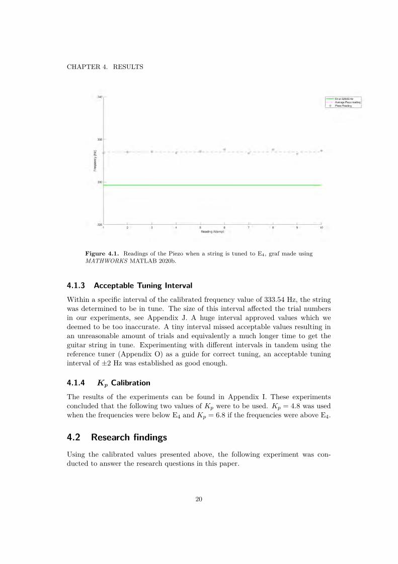
Figure 4.1. Readings of the Piezo when a string is tuned to E4, graf made usingMATHWORKS MATLAB 2020b.
4.1.3 Acceptable Tuning IntervalWithin a specific interval of the calibrated frequency value of 333.54 Hz, the stringwas determined to be in tune. The size of this interval affected the trial numbersin our experiments, see Appendix J. A huge interval approved values which wedeemed to be too inaccurate. A tiny interval missed acceptable values resulting inan unreasonable amount of trials and equivalently a much longer time to get theguitar string in tune. Experimenting with different intervals in tandem using thereference tuner (Appendix O) as a guide for correct tuning, an acceptable tuninginterval of ±2 Hz was established as good enough.
4.1.4 Kp CalibrationThe results of the experiments can be found in Appendix I. These experimentsconcluded that the following two values of Kp were to be used. Kp = 4.8 was usedwhen the frequencies were below E4 and Kp = 6.8 if the frequencies were above E4.
4.2 Research findingsUsing the calibrated values presented above, the following experiment was con-ducted to answer the research questions in this paper.
20

CHAPTER 4. RESULTS
4.2.1 AccuracyFrom figure 4.2, 4.3 and 4.4 the tuning process can be observed. In figure 4.5 theerror from the 30 attempts are shown in Hz and in figure 4.6 the error is in cents.The average error was 0.6 Hz from the target frequency. The accuracy of the tunerwas within the interval -5.14 cents and +3.76 cents. The negative value means belowthe frequency of E4 and the positive value means above. Notice that the referencetuner used for calibration is specified to have an accuracy of ±1 cent. One cent isone hundredth of a semitone.
Figure 4.2. Tuning from D# to E4, graf made using MATHWORKS MATLABR2020b.
21

CHAPTER 4. RESULTS
Figure 4.3. Tuning from F4 to E4, graf made using MATHWORKS MATLABR2020b.
Figure 4.4. Tuning to E4 from a range of starting point betwene D# and F4, grafmade using MATHWORKS MATLAB R2020b.
22

CHAPTER 4. RESULTS
Figure 4.5. Graf over the error of 30 tuning attempts as well as the avrage error,graf made using MATHWORKS MATLAB R2020b.
Figure 4.6. Error for the tune represented in cents, graf made using MATHWORKSMATLAB R2020b.
23

CHAPTER 4. RESULTS
4.2.2 SpeedFigure 4.7 shows the result of how many times the string needed to be plucked in30 tuning attempts.
Figure 4.7. The number of times the string was plucked before it is was in tune. In25 attempts out of 30, the string was in tune after plucking the string twice. Thatmeans that the string was turned to the right frequency after just one iteration of themotor rotating. After plucking the string again, the computer program recognized thefrequency to be within the acceptable tuning interval, graf made using MATHWORKSMATLAB 2020b.
24
Chapter 5
Discussion and Conclusion
5.1 DiscussionDuring the initial tests of the piezoelectric guitar tuner, the end result of the tuningalways ended up at a frequency value below that given by the clip-on reference tuner.
To compensate, the tuner was calibrated so that the frequency detected by thetuner corresponded to the clip-on tuners response of the frequency. The result be-came more accurate towards being actually in tune after the calibration.
One significant part of the construction was the choice of motor. At first, a 5Volt stepper was used. The motor could turn the tuning keys of the guitar howeverwhen the motor had to take few steps, the motor could not manage to create enoughtorque to turn the guitar keys. Therefore a high torque stepper motor, Nema17,was used instead. This motor performed significantly better. But even this motorcan have difficulty turning the guitar key if it only takes small steps. We believethis occurs due tot the fact that it is a stepper motor. With a regular DC motorthere would be a constant torque when active. With a stepper motor the amountof steps are of importance, and the motor probably executed the given amount ofsteps before the torque could turn the key. This results in lowered accuracy of thetuner.
For the project the E4 was used as the proxy for the guitar strings. The E4 tuningkey had the least resistance when turning with the guitar in this project. It shouldbe noted that the guitar used in this project had quite the stiff tuning keys overall.Changing the string to a lighter type of string did have an unrecognizable effect onhow stiff the tuning key became. However, when restringing the guitar, turning thetuning key so that it was as loose as possible before restringing the guitar did affectthe stiffness of the key.
The sampling frequency for the FFT proved to play a major role in detecting the
25

CHAPTER 5. DISCUSSION AND CONCLUSION
frequency of the guitar string. If the Sampling frequency is set too low, the FFTwill not comprehend frequency above half the sampling frequency resulting in aminimal readout. If it is set too high, the FFT will have difficulty reading out afrequency far below half the sampling frequency. In the experiments when the tunerwas tuning from F4 to E4, see Appendix I.2, the readout of the tuner nearly alwayswas 349.23 as the starting frequency. In these tests, the sampling frequency was setto double the frequency of F4. When the string was tuned to be close to F4, thetuner detected 349.23 Hz no matter what. One way to eliminate this is to increasethe sampling frequency. This results in a better readout for when a string is halfa step above the tune. Yet this would also worsen the readout if the guitar stringis tuned a half or a whole step below the supposed tune. A guitar string is rarelymore than one half-step from its original tuning unless the artist explicitly wants itto be. Therefore, it was decided that the sampling frequency will be set to doublethe frequency of one half-step above the tuning of the string.
The target frequency interval was decided as ±2 Hz. This was done after testswere conducted where the interval was set to ±3 Hz. In those experiments, thetuner never ended near the edge of the interval, see Apendix J.5 . The interval wasconsequently shrunk to ±2 Hz. When tried with a closer interval, the tuner hada hard time to finish the tune. This was due to it never ultimately reaching thetarget frequency and kept going back and forth. But also that the tuner sometimespicks up the wrong frequency and sabotages the tuning. When the motor takes afew steps the motor tended to take the steps but the tuning key would not turn anysignificant amount to change the frequency and then the tuner would be stuck.
Sometimes the frequency detected something utterly different than what the stringwas tuned to. At first, we believed that the piezo element somehow got affected bythe noise in the lab-room. That hypothesis quickly got rejected after some testingand what seems to be happening was that other vibrations got generated from thetable of the lab environment or the picking hand touching the guitar body whenplucking the string. It could also have been other strings vibrating as a result ofplucking the E4 string. This is a phenomenon called sympathetic resonance. Sym-pathetic resonance takes place when one string on any multiple-stringed instrumentis plucked. The other strings that are tuned so that they align with the harmonicseries of the frequency of the plucked string also start vibrating [23]. This could alsobe read from the feedback display on the commercially available reference tuner. Tomediate disturbances, a ± 50 Hz of E4 threshold was set up in the software code.If the detected frequency were not within the threshold, the motor would take anysteps. After a string was a plucked all strings were lightly damped by the palm ofthe hand.
When our motor stopped and the program judged the string to be in tune, thereference tuner also showed the string to be in tune. So even though the errorfrom our data was significantly larger than that of the reference tuner, the practical
26

CHAPTER 5. DISCUSSION AND CONCLUSION
difference was unrecognizable, see Appendix O. Most times, the tuner only neededto rotate the motor one time to be in tune. Note that this one time rotation isrecorded as two attempts in the data. The second attempt is to verify for the Ar-duino program that the guitar string is in tune. An interesting comparison is thatthe human ear can notice a difference in pitch of about five to six cents [24], andthe average error for our tuner was −3.4 cents.
5.2 ConclusionA piezoelectric sensor can be used to tune a guitar. The piezo needs to work witha FFT to be able to understand the noted frequencies. The readout of the sensoris strongly connected with the setup. Mainly what sampling frequency used by theFFT affected the readout from the piezo. With proper calibration of the controller,the tuner performed well. The accuracy of the tune was easily on average within-5 cent to +4 cents or ±2Hz of the target frequency. Compared to the commercialtuner used to compare, it showed us to be perfectly in tune. On average, the tuningwas -3 cents of the target frequency. The human ear can notice differences of 5-6cents. With the correct values of Kp , the constant for the p-controller, the tunercould most times rotate the tuning key so the string was in tune on its first try.
27

Chapter 6
Future work
A development of this project could be to create a device that can tune all stringswithout specifying which tuning key the device is mounted on. This could be donejust by categorizing the piezo readings into different intervals belonging to eachstring. In order to make this work a stronger motor is needed to handle the inertiaof the stiffer strings.
An integrated design is appropriate in order to make the device more user friendly.This would albeit be a nice expansion of this device for a project more orientedtowards the design aspects of construction. Everything needs to be able to fit insidesomething that can be handheld.
The tuner in this project uses a P-controller to control the amount steps takenby the stepper motor. This can be developed to be a PID-controller which wouldbe more accurate. However, for our tests with the E4 string a P-controller are morethan sufficient to get a decent result.
28

Bibliography
[1] Gylling, M and Svensson, DEGREE PROJECT IN TECHNOLOGY, FIRSTCYCLE, 15 CREDITS KTH STOCKHOLM, SWEDEN 2017 Robotic ElectricGuitar Tuner ,KTH, 2017. Available [Onl ine]:http://www.diva-portal.org/smash/get/diva2:1200615/FULLTEXT01.pdf
[2] Glad,T Ljung, L. Reglerteknik: Grundlaggande Teori Studentlitteratur AB.4:16 th edition. October 2006. [Book] ISBN 978-91-44-02275-8
[3] French, R. Engineering the Guitar Theory and Practice New York, NY :Springer US : Imprint: Springer [Book] Available [Online]:https://kth-primo.hosted.exlibrisgroup.com/permalink/f/qra184/46KTH_ALMA_DS51174906940002456
[4] En Liten Bok Om Musikteori Wise publications,2001. Oversattare Ola Eriksson.[Book]
[5] Sauveur, J Principes d’acoustique et de musique, ou Systeme general desintervalles des sons et de son application a tous les systemes et a tous les instru-ments de musique. Inserted in the ”Memoires” of 1701 of the Royal Academy ofSciences, by M. Sauveur. Date access: 2021-02-15. Available [Online]:https://kth-primo.hosted.exlibrisgroup.com/permalink/f/1vh8pa3/TN_cdi_bnf_primary_oai_bnf_fr_gallica_ark_12148_bpt6k1510877z
[6] Fourier, J-B.J. Theorie analytique de la chaleur Paris, Gallica Ebooks Available[Online]:https://kth-primo.hosted.exlibrisgroup.com/permalink/f/1vh8pa3/TN_cdi_bnf_primary_oai_bnf_fr_gallica_ark_12148_bpt6k1045508v
[7] Vretblad, A. Fourier Analysis and its Applications 2003, New York, NY:Springer, Available [Online]:https://kth-primo.hosted.exlibrisgroup.com/permalink/f/1vh8pa3/TN_cdi_springer_books_10_1007_b97452
29

BIBLIOGRAPHY
[8] Pring, J. (1965). The Oxford dictionary of modern Greek Oxford: Claren-don.[Book]
[9] Manbachi, A, Cobbold, R. S. C. Development and Application of PiezoelectricMaterials for Ultrasound Generation and Detection. Ultrasound, 19(4), 187-196.Date access: 2021-02-15 Available [Online]:https://kth-primo.hosted.exlibrisgroup.com/permalink/f/1vh8pa3/TN_cdi_crossref_primary_10_1258_ult_2011_011027
[10] Arduino Uno Date access: 2021-02-05 [Online] Available:https://store.arduino.cc/arduino-uno-rev3:
[11] Barr, M. Pulse Width Modulation Embedded Systems Programming, Septem-ber 2001, pp.103-104. Date access: 05-02-2021. Available [Online] :https://barrgroup.com/Embedded-Systems/How-To/PWM-Pulse-Width-Modulation
[12] Overview of the Arduino pin Overview of the Arduino pins. Date access.2021-02-16 Available [Online]:https://www.electronicwings.com/arduino/arduino-uno-r3-board
[13] Basics of stepper motor Date access: 2021-02-15. Available [Online]:https://www.orientalmotor.com/stepper-motors/technology/stepper-motor-basics.html
[14] Stepper Motor Date access: 2021-02-24 Available [Online]:https://www.monolithicpower.com/stepper-motors-basics-types-uses
[15] The difference between unipolar and bipolar stepper motors Date Access:2021-04-10. Available [Online]:https://techexplorations.com/blog/arduino/blog-the-difference-between-unipolar-and-bipolar-stepper-motors/
[16] Unipolar and Bipolar stepper motor Date Access: 2021-04-10. Available[Online]https://blog.orientalmotor.com/wiring-basics-unipolar-vs-bipolar
[17] Johansson, H.B. Elektroteknik 2013, KTH, Department of Machine Design[Book]
[18] Actobatic-axle-hub Date Access: 2021-04-26. Available [Online]https://www.electrokit.com/produkt/actobotics-axelnav-med-fastskruv-5mm/
[19] Adafruit Stepper Motor driver Date access: 2021-04-26. Available [Online]:https://www.adafruit.com/product/2448l
30
BIBLIOGRAPHY
[20] AudioFrequncyDetector with FFT Date Access: 2021-03-20. Available [Online]:https://clydelettsome.com/blog/2019/12/18/my-weekend-project-audio-frequency-detector-using-an-arduino/
[21] ArduinoFFT Date Access: 2021-03-15. Available [Online]:https://www.arduino.cc/reference/en/libraries/arduinofft/
[22] Stepper motor software Date Access 2021-03-10. Available [Online]:https://lastminuteengineers.com/28byj48-stepper-motor-arduino-tutorial/
[23] Rossing, T.D. The Science of String Instruments 2010 Springer [Book]Available [Online]:https://kth-primo.hosted.exlibrisgroup.com/permalink/f/1vh8pa3/TN_cdi_askewsholts_vlebooks_9781441971104
[24] Loeffler, D.B. Instrument Timbres and Pitch Estimation in Polyphonic Music,Georgia Institute of Technology, 2006. Date access: 2021-05-05. Available[Online]:https://web.archive.org/web/20060914233900/http://etd.gatech.edu/theses/available/etd-04102006-142310/unrestricted/loeffler_dominik_b_200605_mast.pdf
[25] 14 relevant parts of an acoustic guitar. Date Access: 2021-03-15. Available[Online]:https://bestbeginnerguitartoday.com/parts-of-an-acoustic-guitar/
[26] Korg AW2G Clip-On Chromatic Guitar Tuner Date Access: 2021-04-27.Available [Online]:https://www.amazon.com/Korg-AW2G-Clip-Chromatic-Guitar/dp/B001XJBWXG?th=1
[27] Pitchclip 2 Clip-on Tuner Date Access: 2021-04-30. Available [Online]:https://www.korg.com/se/products/tuners/pitchclip2/specifications.php
31

Appendix A
Component list
• Set screw hub (5mm). Appendix M.
• Arduino Uno Microcontroller Board (Playknowlogy Uno Rev. 3. model). Fordatasheet see reference [10].
• Battery (12V) from Yuasa.
• Battery snap (for 9V battery).
• Battery (9V lithium) *.
• Capacitor (100µF),
• Clip-on tuner (Korg Pitchclip 2) used for calibration. Appendix O.
• Clip-part de-assembled from a ’Clip-On Guitar Tuner’ (Korg AW2G) Appendix N.
• Grip for Tuning Key, 3D printed according to blueprint in Appendix E.
• Jumper wires of appropriate length *.
• Heat sink 20x20mm *.
• Piezo element (9 kHz, Murata)
• Resistor (10MΩ ).
• Stepper Motor (Bipolar, Nema 17), Appendix D.
32

APPENDIX A. COMPONENT LIST
* No further specification required in order to replicate the construction described above.These parts are elementary and any corresponding version with similar measurements canbe used equivalently.
33

Appendix B
Glossary
fretting pressing a finger somewhere on the fretboard to get a certain noteopen string playing a guitar string without fretting
34
Appendix C
Parts of an acoustic guitar
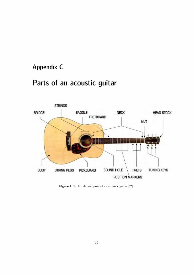
Figure C.1. 14 relevant parts of an acoustic guitar [25].
35

Appendix D
Stepper Motor Datasheet: Nema 17
36

! " # $ % & ' ( ) * + , - ) . / 0 . + , 1 * + , 2 * ( ) 3 + 4 5 1 6 4 7 4 ( 8 5 . + 3 ( 09 : ; < : = > 9 ? = ? 9 @ < ? < A < : B C D E F G D H I D J F K G B G J F L
M N O P Q R S T U V M W X Y X N Z [ P Q Z P X \ ] ] S Z P T ^ _ U Q Y ` Q O a [ P S bc d e f g h i j e k lm n o p q r s t u v w x qy z | ~ z ~ z
¡ ¢ £ £ ¤ ¥ ¦§ ¨ © ª «¬ ® ¯ ° ± ² ³ ´ µ ° ± ® ®¶ · ¸ ¹ º » ¼ ½ ¸ · ¾ ¹ ¿ » ÀÁ Â Ã Ä Å Æ Ç È È Ä É Ã Ê Ë ÌÍ Î Ï Ð Ï Ñ Ò Ó Ô Î Õ Î Ö Õ × Ò Ï Î Ø Ù Ú ÛÜ Ý Þ ß à á â Ý à ã ä ã å ä æ â ç ã è é ê ë ì íî ï ð ñ ò ó ô õ ï ö ÷ ø ù ú û ô ü ý þ ÿ
100M ¸ Min ! " # $ %& ' '() * + , - . / / - * 0 - 1 2 / 3 1 - 4 5 6 7 8 9 : ; 9< = > ? = @ A B C @ = D E F = G H I
J K L M K L N K O P Q R S T U V WX Y Z [ \ Y ] ^ Y _ ` a \ b c d e f g h i j k l l m n o l p q r m s t u v r wx y z | ~
¡ ¡ ¢ £ ¤ ¥
¦ § ¨ © ª «¬ ® ¯ ° ± ² ³ ³ ´ µ µ ¶ ³ ³ · ¸ · ¹ º » ¼ ½ ¾ ¿ À » ¼ ½ Á ¿  ¿ à ¿Ä Ä Å
Æ ÇÈÉ

Appendix E
Blueprint Tuning Key Gripper
38
Appendix F
Arduino Code
1 /*2 File/Sketch Name: Guitar Tuner3 School: KTH Royal Institute of Technology4 Made by: Albin Boestad & Fabian Rudberg5 Created: 2021-04-09 Version 1.0:6 Trita:-ITM-EX 2021:2478 Description: This code is based on the
AudioFrequencyDetection code written by Clyda.ALettersome
9 and can be found: https://clydelettsome.com/blog/2019/12/18/my-weekend-project-audio-frequency-detector-using-an-arduino/
10 This code detects the frequency detetctet from a piezosensor on a guitar. The frequncy is compared
11 to see if the string is in tune. Then the Arduino controlsthe stepper motorto adjust the tuning peg
12 so the guitar is in tune.1314 The piezo elemment sends a analog adio signal to A0 on the
Arduino Uno and then gets sampled.15 A Fast Fourier Tranfrom(FFT) is used on the data using the
library arduinoFFT.h. The FFT transform16 the signal from the time doma to the frequency domain.
The maximum frequency detetcted is determined.17 The frequencys is displays using the Arduino Serial Monitor
and is compared to the frequency of a in18 tune string. Then a stepper motor is rotated based on how
wrong the frequency is.19 */
39

APPENDIX F. ARDUINO CODE
20 //Includes the arduinoFFT library as well as the Stepperlibrary.
21 #include <arduinoFFT.h>22 #include <Stepper.h>2324 //float freqarray[] = 82.41, 110, 146.83,196.00, 246.94,
329.63; //329.63Standrad frequency for a guitar infollowing order [E2, A2, D3, G3, B3, E4]
25 float piezoarray[] = 333.54; //This frequncy is theavrage readout for the piezo when the string is tuned toE4
2627 #define SAMPLES 128 //Sets the amount of samples
that will be taken for the FFT. Must be a base 2 number.Max 128 for Arduino Uno.
28 #define SAMPLING_FREQUENCY 698.46//Based on Nyquist, must be2 times the highest expected frequency. For the guitarE4 is the highest frequency.
29303132 unsigned int samplingPeriod; //Creates an int for the
sampling period33 unsigned long microSeconds; //creats a long for the
microSeconds3435 double vReal[SAMPLES]; //create vector of size SAMPLES to
hold real values36 double vImag[SAMPLES]; //create vector of size SAMPLES to
hold imaginary values3738 // Number of steps per internal motor revolution39 const float STEPS_PER_REV = 200;404142 // Setups the steppermotor, creaets an Stepper class named
steppermotor.43 // Specifies the pins that going to the stepper driver. The
pins that are44 // used are 8,9,10,11 that connects to In1, In2, IN3, In4 on
the stepper45 // motor driver board ULN2003. The pins need to be entered
in the sequence46 // 1-3-2-4 to be able to make the proper steps sequencing
40
APPENDIX F. ARDUINO CODE
47 Stepper steppermotor(STEPS_PER_REV, 7,8,10,13);48 //Creates a instance of arduinoFFT class named FFT.49 arduinoFFT FFT = arduinoFFT();5051 // Define Variables5253 int StepsRequired;//StepsRequired is the amount steps that
are needed to turn.54 float Difference;55 int var = 1; // Var is variable that changes depending on
which case the code is in56 int t = 0; //t is a variabel that changes which string we
are tuning. As of this version only E4 is tuned andtherefore is t set to 0.
57 float factor ; //Factor for the P-regulator. Facktor = 4.8is good when below E4 and factor = 6.8 is good when aboveE4.
5859 void setup()60 61 Serial.begin(115200); //Baud rate for the Serial Monitor62 samplingPeriod = round(1000000*(1.0/SAMPLING_FREQUENCY))
; //Period in microseconds6364 steppermotor.setSpeed(250);6566 6768 void loop()69 7071 if(var ==1)72 73 int var = 1; // Sets varible to 1 so that case 1 is
running.74 7576 if(var !=1)77 78 int var = var; //Sets the varible so that i does not
change. If it is in case 2 it stays in cse 2. Case 2 iswhen the tuning is finished.
79 80
41

APPENDIX F. ARDUINO CODE
81 switch(var)8283 case 1: //Case 1 Case 1 is where it does sampling and
turns the stepper motor8485 Serial.print("\n");86 Serial.print("New reading");87 Serial.print("n");88 delay(1000);89909192 /*Sample SAMPLES times*/93 for(int i=0; i<SAMPLES; i++)94 95 microSeconds = micros(); //Returns the number of
microseconds since the Arduino board beganrunning the current script.
9697 vReal[i] = analogRead(A0); //Reads the value from
analog pin 0 (A0), quantize it and save it as areal term.
98 vImag[i] = 0; //Makes imaginary termalways 0
99100 /*remaining wait time between samples if necessary*/101 while(micros() < (microSeconds + samplingPeriod))102 103 //do nothing104 105106 107108109110 /*Perform FFT on samples*/111 FFT.Windowing(vReal, SAMPLES, FFT_WIN_TYP_HAMMING,
FFT_FORWARD);112 FFT.Compute(vReal, vImag, SAMPLES, FFT_FORWARD);113 FFT.ComplexToMagnitude(vReal, vImag, SAMPLES);114115 /*Find peak frequency and print peak*/116 double peak = FFT.MajorPeak(vReal, SAMPLES,
SAMPLING_FREQUENCY);
42

APPENDIX F. ARDUINO CODE
117118 /*Print out on Serial Monitor*/119 Serial.print("\n");120 Serial.print("Peak frequency:");121 Serial.print("\n");122 Serial.println(peak); //Print out the most dominant
frequency.123124 /*Depending on which string and what frequencys was
detetcted the following happens*/125 if (peak<=(piezoarray[t]+50) && (piezoarray[t]-50)<=peak)126 // The motor will only rotate if peak frequency is not to
far away.127 //This is a measurment incase the sampling went wrong and
the detetcted peak frequencys is wrong128 129 if((piezoarray[t]-2)<= peak && peak <= (piezoarray[t]+2)
) //If the sampled frequencys is withing130 //an interval of +-2 Hz, we say it is in tune131 /*Writes on seriel monitorn the following*/132 Serial.print("String is in tune");133 Serial.print("\n");134 var = 2; //Switches var so the case
will switch to case 2135 delay(3000); //Waits 3 seconds, usefull to
able to see what happens136 //on Serial Monitor as well
as the motors rotation.137 break; //breaks the case and returns
to the loop138 139140 Difference = (piezoarray[t]-peak); //
Calculates the differences of the peak andintune frequncy.
141 /*Prints out the following in serial monitor
*/142 Serial.print("Diffrences:");143 Serial.print(piezoarray[t]-peak);144 Serial.print("\n");145 Serial.print("Amount of steps ");146147148
43

APPENDIX F. ARDUINO CODE
149 if (Difference<=0) //If we are above E4 tehdifferences will be neagtive.
150 151 faktor = 6.8; //Facktor set to 6.8 will
be used if the detected frequncy is aboveE4
152 StepsRequired = Difference*faktor; //Stepsthe motor needs to take
153 154 else155 156 faktor = 4.8; //If the differences is
positive the detetcted frequncy is belowE4, and
157 //the factor = 4.8 willbe used
158 StepsRequired = Difference*faktor; //Stepsthe motor needs to take
159 160 Serial.print(StepsRequired);161 delay(1000);162 Serial.print("\n");163 steppermotor.step(StepsRequired); //
Rotatates the motor StepsRequired step.164 delay(2000);165 166 memset(vReal, 0, sizeof(vReal)); //Makes sure that all
values in vReal is set to zero before a new sampling167 break; // G r ut case 1168169170 case 2: //When the string is in tune a led is lit up by
seting pin 2 to HIGH.171172 //Do nothing when the string is in tune173174 ;175 176177178
44
Appendix G
Acumen Simluation
//Simulation Piezoelectric guitar tuner// SChool: KTH Royal Institute of Technology//Made by: Albin BOestad & Fabian Rudberg// Created: 2021-03-23// Trita: ITM-EX 2021:24
//Description: Simulation of the piezoelectri guitartuner.//The tuner will rotate a grip that is attached to the// guitar tunning key.//The tuner will be able to rotate the the tuning key in//both direction depending if the string needs to be//tightened or loosened.
model box (x,y,z) = //Creates a box which has its center// in koordinates (x,y,z).
initially_3D = ()
always
_3D =(Box //Creates a box the represents all
//the electronics for the tuner.center=(x,y, z)size=(10, 7, 12) //The size of the box is given// on the form (x, y, z)
45

APPENDIX G. ACUMEN SIMLUATION
color = white)
model cyl_ (x,y,z,a) = //Creates a cylinder. In data is// the center of the cylinder and//the angle,"a", that the cylinder// should rotateinitially_3D = ()always
_3D = (Cylinder //Creates model of the griper that//will attach to the tuning key.
center = (x, y,z)
size = (2, 2) //Size if the cylinder is given// as (hight, radius).
color = yellowrotation = (0,a,0) //Tells the model to rotate around
//the y-axle with the angle a.)
model peg (x,y,z,a) = //Model of the tuning key
initially_3D = ()
always_3D =
(Boxcenter=(x,y, z)size=(0.5, 1, 5)color = bluerotation = (0,a,0)) //Tells the model to rotate around
// the y-axle with angle a. The same//rotation for both the tning key
//model as the grip model
model Main(simulator) =initially //THe following code is run only once
b = create box(0,0,-4), //Creates the obejct boxc = create cyl_(0, -4.5, -1,0), //Creates the object cylindertp = create peg(0, -5.5, -1,0), //Creates the obejct tuning key
t = 0, t’=0, //Time starts at Zero and does not accelrate
46
APPENDIX G. ACUMEN SIMLUATION
a = 0, a’ = 0 //Angle "a" is zero in the beginning and the angular//velocity, a’, is zero.
always //Following code is run constantly.n.t’=1, //Decides the speed of the simluation. With t’ = 1 the time
//will move with 1 second/second// Sets the angular velocity to 1 when t<3, corresponds
//to the Arduino tells the motor to rotate// in one direction a certain amount of steps.if t<= 3 then
a’ = 1
//Here the motor has rotate in one direction but rotate//to far and therefore rotates back
else if 3<t && t<= 6 thena’ = -1 //The minus corresponds to rotate in the
//other direction
//After thiscorrectio we are still to far of so the//tuner makes one last rotationelse if 6<t && t<=7 then
a’=1
//Now the tuner says the guitar is in tuneelsea’ = 0, // When the angular velocity is set to zero the model
//stops rotatingangle ac.a = a, //Send to the cylinder model that it shall rotate with//the the angle ’a’. By sending this comand constantly//the model will make a rotating motion
tp.a =a //Send to the tuning key model that it shall rotate with// the the angle ’a’. By sending this comand constantly//the model will make a rotating motion
47

Appendix H
Piezo Calibration Data
Table H.1. Tuning the E4 string to the E4-frequency of 329.63Hz according tothe tuner and noting the equivalent frequency as detected by the Piezo-element (andapproximated as frequency through the FFT-algorithm). For Pitchclip 2 specs, seeAppendix O and for Piezo-element specification, see Appendix ??
.
Pitchclip 2 - Frequency *Piezo - Frequency329.63 333.40329.63 333.49329.63 333.56329.63 333.40329.63 333.58329.63 333.81329.63 333.35329.63 333.79329.63 333.31329.63 333.67
* The average piezo-frequency value for E4 became 333.52 Hz.
48

APPENDIX H. PIEZO CALIBRATION DATA
Table H.2. Tuning the E4 string to the D#-frequency of 311.13Hz according tothe tuner and noting the equivalent frequency as detected by the Piezo-element (andapproximated as frequency through the FFT-algorithm). For Pitchclip 2 specs, seeAppendix O and for Piezo-element specification, see Appendix ??
.
Pitchclip 2 - Frequency *Piezo - Frequency311.13 314.13311.13 314.00311.13 315.11311.13 314.71311.13 314.18311.13 313.88311.13 314.89311.13 313.82311.13 310.41311.13 313.70
* The average piezo-frequency value for D# became 314.18 Hz.
49

APPENDIX H. PIEZO CALIBRATION DATA
Table H.3. Tuning the E4 string to the F-frequency of 349.23Hz according to thetuner and noting the equivalent frequency as detected by the Piezo-element (andapproximated as frequency through the FFT-algorithm). For Pitchclip 2 specs, seeAppendix O and for Piezo-element specification, see Appendix ??
.
Pitchclip 2 - Frequency *Piezo - Frequency349.23 349.23349.23 347.26349.23 349.23349.23 349.23349.23 349.23349.23 349.23349.23 349.23349.23 349.23349.23 349.23349.23 349.23
* The average piezo-frequency value for F became 349.03 Hz.
50

Appendix I
Calibration data for the constant ofproportional control, Kp
I.1 Tuning from D#4 to E4.
Table I.1. Kp = 3.0. Test 1.
.
Iteration Frequency Steps1 314.59 562 352.42 243 331.87 54 332.61 0
Table I.2. Kp = 5.0. Test 1.
.Iteration Frequency Steps
1 314.19 962 334.27 0
51
APPENDIX I. CALIBRATION DATA FOR THE CONSTANT OF PROPORTIONALCONTROL, Kp
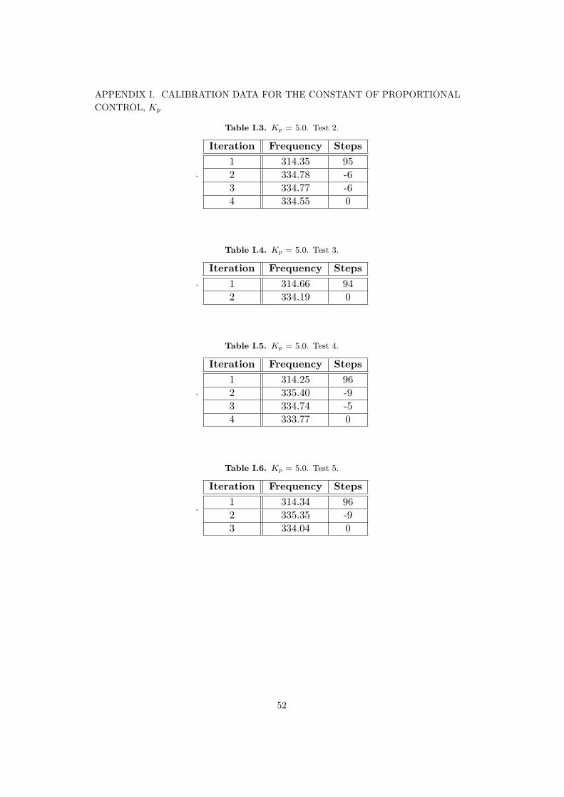
Table I.3. Kp = 5.0. Test 2.
.
Iteration Frequency Steps1 314.35 952 334.78 -63 334.77 -64 334.55 0
Table I.4. Kp = 5.0. Test 3.
.Iteration Frequency Steps
1 314.66 942 334.19 0
Table I.5. Kp = 5.0. Test 4.
.
Iteration Frequency Steps1 314.25 962 335.40 -93 334.74 -54 333.77 0
Table I.6. Kp = 5.0. Test 5.
.
Iteration Frequency Steps1 314.34 962 335.35 -93 334.04 0
52

APPENDIX I. CALIBRATION DATA FOR THE CONSTANT OF PROPORTIONALCONTROL, Kp
Table I.7. Kp = 4.5. Test 1.
.Iteration Frequency Steps
1 313.84 882 333.94 0
Table I.8. Kp = 4.5. Test 2.
.
Iteration Frequency Steps1 314.63 852 331.30 103 333.99 0
Table I.9. Kp = 4.5. Test 3.
.
Iteration Frequency Steps1 314.44 852 331.47 93 333.99 0
Table I.10. Kp = 4.8. Test 1.
.Iteration Frequency Steps
1 314.58 912 334.34 0
Table I.11. Kp = 4.8. Test 2.
.Iteration Frequency Steps
1 313.20 972 333.95 0
53

APPENDIX I. CALIBRATION DATA FOR THE CONSTANT OF PROPORTIONALCONTROL, Kp
Table I.12. Kp = 4.8. Test 3.
.
Iteration Frequency Steps1 314.56 912 331.29 103 334.85 -64 334.99 -65 334.55 -56 334.11 0
Table I.13. Kp = 4.8. Test 4.
.Iteration Frequency Steps
1 314.58 912 334.00 10
Iteration Frequency Steps1 314.57 912 333.35 0
Table I.14. Kp = 4.8. Test 5.
.
54
APPENDIX I. CALIBRATION DATA FOR THE CONSTANT OF PROPORTIONALCONTROL, Kp
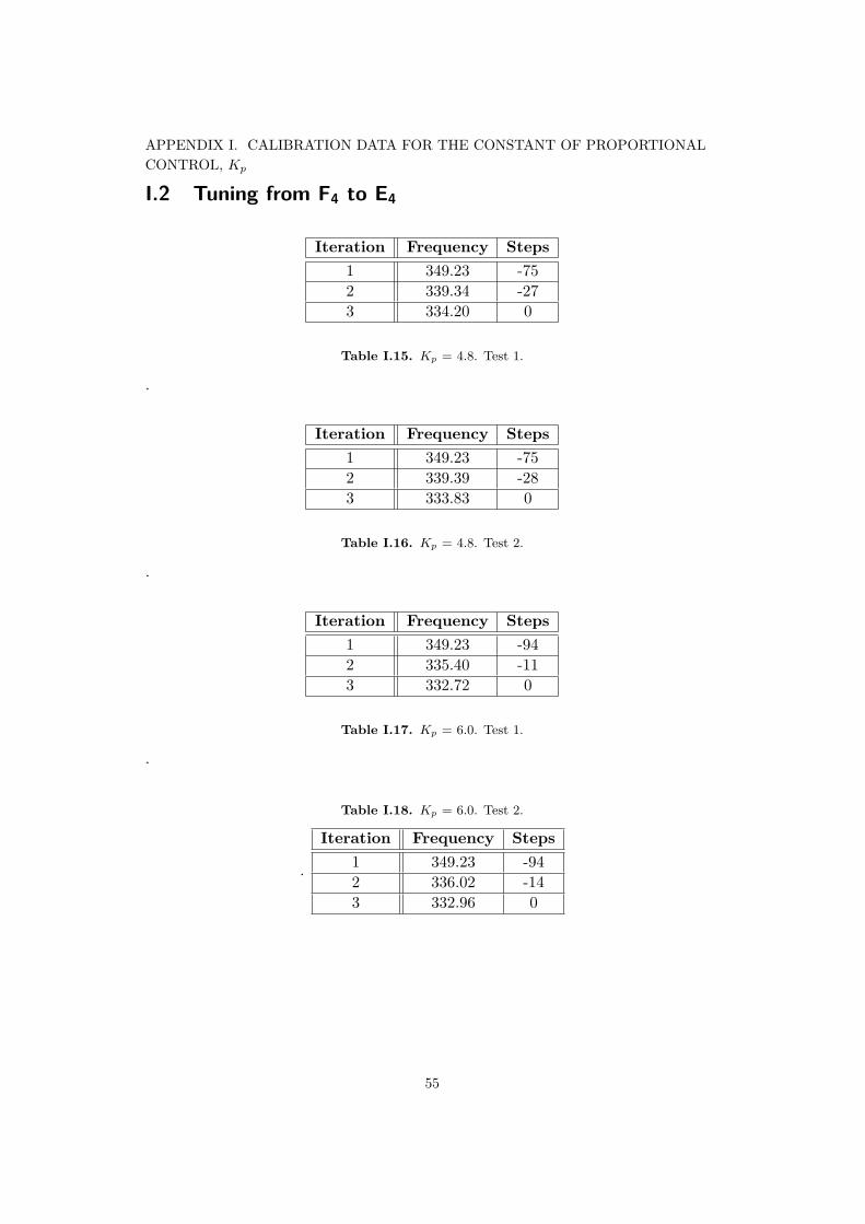
I.2 Tuning from F4 to E4
Iteration Frequency Steps1 349.23 -752 339.34 -273 334.20 0
Table I.15. Kp = 4.8. Test 1.
.
Iteration Frequency Steps1 349.23 -752 339.39 -283 333.83 0
Table I.16. Kp = 4.8. Test 2.
.
Iteration Frequency Steps1 349.23 -942 335.40 -113 332.72 0
Table I.17. Kp = 6.0. Test 1.
.
Table I.18. Kp = 6.0. Test 2.
.
Iteration Frequency Steps1 349.23 -942 336.02 -143 332.96 0
55

APPENDIX I. CALIBRATION DATA FOR THE CONSTANT OF PROPORTIONALCONTROL, Kp
Table I.19. Kp = 7.0. Test 1.
.
Iteration Frequency Steps1 349.23 -1092 331.62 133 333.93 0
Table I.20. Kp = 6.5. Test 1.
.Iteration Frequency Steps
1 349.23 -1012 334.22 0
Table I.21. Kp = 6.5. Test 2.
.
Iteration Frequency Steps1 349.23 -1012 334.61 -63 333.48 0
Table I.22. Kp = 6.5. Test 3.
.Iteration Frequency Steps
1 349.23 -1012 333.78 0
Table I.23. Kp = 6.8. Test 1.
.Iteration Frequency Steps
1 349.23 -1062 333.63 0
56

APPENDIX I. CALIBRATION DATA FOR THE CONSTANT OF PROPORTIONALCONTROL, Kp
Table I.24. Kp = 6.8. Test 2.
.Iteration Frequency Steps
1 349.23 -1062 332.65 0
Table I.25. Kp = 6.8. Test 3.
.Iteration Frequency Steps
1 349.23 -1062 333.83 0
57

Appendix J
Results Appendix
J.1 Data Tables. One half-step below and above E4.Acceptable tuning interval ±3. K = 5. Non-calibratedreference frequency for Piezo.
58

APPENDIX J. RESULTS APPENDIX
Table J.1. Automatically tuning from D#4 to E4 with proportional constant, K=5,and acceptable tuning interval equal to ±3 Hz
.
Attempt* Tuner Freq. [Hz] Piezo Freq. [Hz] Steps** Trials***1 311.13 313.86 78
329.83 22 311.13 314.39 76
330.05 23 311.13 314.47 75
329.74 24 311.13 313.63 80
330.17 25 311.13 313.85 78
330.28 26 311.13 313.82 79
330.37 27 311.13 314.85 73
329.72 28 311.13 314.57 75
349.23 -98311.22 92329.05 4
9 311.13 314.07 77329.48 2
10 311.13 349.23 -98292.95 183330.45 3
* The E4 - string count as ’in tune’ when within the interval of 329.63 +/- 3 Hz. This isfor uncalibrated piezo-frequency and with a wider larger interval than later was shown tobe more effective.** Negative sign (-) before recorded steps means clockwise rotation*** One trial means hitting the string once and getting a response-measurement
59

APPENDIX J. RESULTS APPENDIX
Table J.2. Automatically tuning from F4 to E4 with proportional constant, K=5,and acceptable tuning interval equal to ±3 Hz
.
Attempt Tuner Freq. [Hz] Piezo Freq. [Hz] Steps Trials1 349.23 349.23 -98
335.18 -27329.70 3
2 349.23 349.23 -98335.17 -27329.67 3
3 349.23 349.23 -98334.75 -25330.68 3
4 349.23 349.23 -98334.70 -25330.16 3
5 349.23 349.23 -98334.35 -23329.68 3
6 349.23 349.23 -98333.81 -20329.25 3
7 349.23 349.23 -98334.96 -26330.03 3
8 349.23 349.23 -98334.92 -26329.77 3
9 349.23 349.23 -98349.23 -98313.27 81329.47 4
10 349.23 348.36 -93339.03 -47329.70 3
60

APPENDIX J. RESULTS APPENDIX
J.2 Data Tables. One half-step below and above E4.Acceptable tuning interval ±2. K = 4.8. CalibratedPiezo-frequency.
Table J.3. Automatically tuning from D#4 to E4 with proportional constant,K=4.8, and acceptable tuning interval equal to ±2 Hz
.
Attempt* Tuner Freq. [Hz] Piezo Freq. [Hz] Steps** Trials***1 311.13 314.13 93
328.21 25337.87 -29334.50 0 4
2 311.23 314.00 93334.44 0 2
3 311.23 315.11 88331.16 11332.59 0 3
4 311.23 314.71 90332.23 0 2
5 311.23 314.18 92332.57 0 2
6 311.23 313.88 84333.57 0 2
7 311.23 314.89 89333.34 0 2
8 311.23 313.82 94333.04 0 2
9 311.23 310.41 111332.48 0 2
10 311.23 313.70 95333.29 0 2
* The E4 - string count as ’in tune’ when within the interval of 333.52 +/- 2 Hz. Thevalue of 333.52 piezo-calibrated according to Appendix H** Negative sign (-) before recorded steps means clockwise rotation*** One trial means hitting the string once and getting a response-measurement
61

APPENDIX J. RESULTS APPENDIX
Table J.4. Automatically tuning from F to E4 with proportional constant, K=4.8,and acceptable tuning interval equal to ±2 Hz
.
Attempt Tuner Freq. [Hz] Piezo Freq. [Hz] Steps Trials1 349.23 349.23 -106
331.90 0 22 349.23 347.26 -93
334.94 0 23 349.23 349.23 -106
331.63 0 24 349.23 349.23 -106
333.20 0 25 349.23 349.23 -106
333.20 0 26 349.23 349.23 -106
332.25 0 27 349.23 349.23 -106
332.96 0 28 349.23 349.23 -106
332.81 0 29 349.23 349.23 -106
330.85 12331.72 0 3
10 349.23 349.23 -106332.18 0 2
62

APPENDIX J. RESULTS APPENDIX
J.3 Data Tables. Five points between D#4 and E4.Acceptable tuning interval ±2. K = 4.8. CalibratedPiezo-frequency.
Attempt Piezo freq. Steps Trials1 320.25 63
333.23 0 22 323.93 50
331.67 0 23 325.94 36
333.00 0 24 327.88 27
333.00 0 25 330.18 16
333.97 0 2
63
APPENDIX J. RESULTS APPENDIX
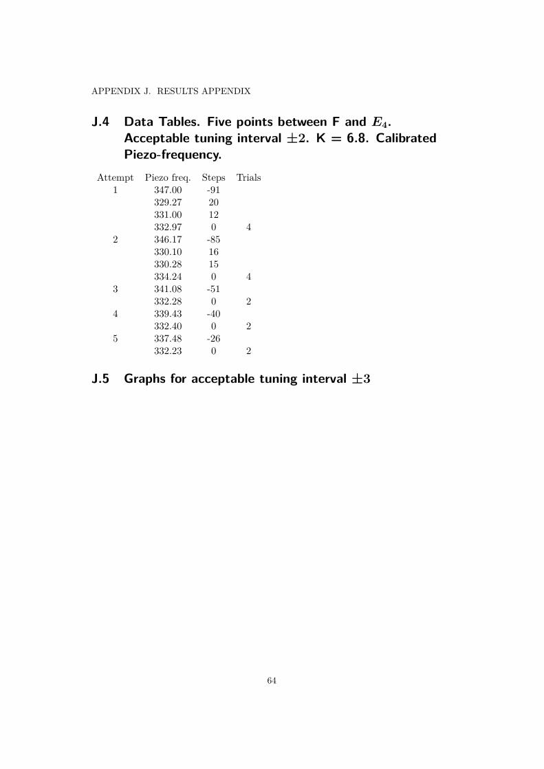
J.4 Data Tables. Five points between F and E4.Acceptable tuning interval ±2. K = 6.8. CalibratedPiezo-frequency.
Attempt Piezo freq. Steps Trials1 347.00 -91
329.27 20331.00 12332.97 0 4
2 346.17 -85330.10 16330.28 15334.24 0 4
3 341.08 -51332.28 0 2
4 339.43 -40332.40 0 2
5 337.48 -26332.23 0 2
J.5 Graphs for acceptable tuning interval ±3
64

APPENDIX J. RESULTS APPENDIX
Figure J.1. Graf of tuning from D# to E4 with a +-3Hz acceptable tuning interval,graf was made using emphMATHWORKS MATLAB R2020b
65
APPENDIX J. RESULTS APPENDIX
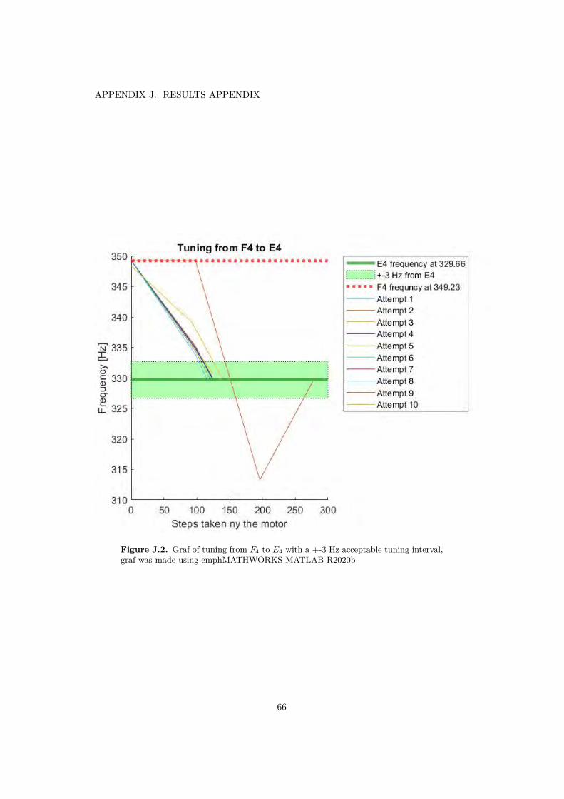
Figure J.2. Graf of tuning from F4 to E4 with a +-3 Hz acceptable tuning interval,graf was made using emphMATHWORKS MATLAB R2020b
66

Appendix K
Adafruit Stepper Motor driver
67

Adafruit TB6612 1.2A DC/Stepper Motor Driver BreakoutBoard
Created by lady ada
Last updated on 2020-11-20 05:59:31 PM EST

Overview
Fire four solenoids, spin two DC motors or step one bi-polar or uni-polar stepper with 1.2A per channel
using the TB6612. These are perhaps better known as "the drivers in our assembled Adafruit
Motorshield (http://adafru.it/1438) or Motor HAT (https://adafru.it/eRq)" We really like these dual H-bridges,
so if you want to control motors without a shield or HAT these are easy to include on any solderless
breadboard or perma-proto.
We solder on TB6612 onto a breakout board for you here, with a polarity protection FET on the motor
voltage input and a pullup on the "standby" enable pin. Each breakout chip contains two full H-bridges
(four half H-bridges). That means you can drive four solenoids, two DC motors bi-directionally, or one
stepper motor. Just make sure they're good for 1.2 Amp or less of current, since that's the limit of this chip.
© Adafruit Industries https://learn.adafruit.com/adafruit-tb6612-h-bridge-dc-stepper-motor-driver-breakout Page 3 of 20

They do handle a peak of 3A but that's just for a short amount of time, about 20 milliseconds. What we
like most about this particular driver is that it comes with built in kick-back diodes internally so you dont
have to worry about the inductive kick damaging your project or driver!
There's two digital inputs per H-bridge (one for each half of the bridge) as well as a PWM input per driver
so you can control motor speed. Runs at 2.7V-5V logic. The motor voltage is separate from the logic
voltage. Good for motor voltages from 4.5V up to 13.5V! This wont work well for 3V motors.
Comes as one assembled and tested breakout plus a small strip of header. You'll need to do some light
soldering to attach the header onto the breakout PCB. Arduino, motors, and power supply not included.
© Adafruit Industries https://learn.adafruit.com/adafruit-tb6612-h-bridge-dc-stepper-motor-driver-breakout Page 4 of 20

© Adafruit Industries https://learn.adafruit.com/adafruit-tb6612-h-bridge-dc-stepper-motor-driver-breakout Page 5 of 20
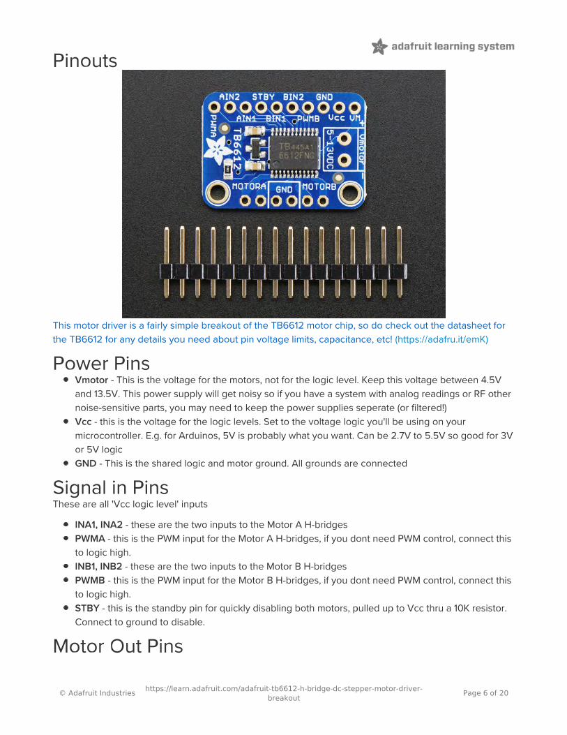
Pinouts
This motor driver is a fairly simple breakout of the TB6612 motor chip, so do check out the datasheet for
the TB6612 for any details you need about pin voltage limits, capacitance, etc! (https://adafru.it/emK)
Power PinsVmotor - This is the voltage for the motors, not for the logic level. Keep this voltage between 4.5V
and 13.5V. This power supply will get noisy so if you have a system with analog readings or RF other
noise-sensitive parts, you may need to keep the power supplies seperate (or filtered!)
Vcc - this is the voltage for the logic levels. Set to the voltage logic you'll be using on your
microcontroller. E.g. for Arduinos, 5V is probably what you want. Can be 2.7V to 5.5V so good for 3V
or 5V logic
GND - This is the shared logic and motor ground. All grounds are connected
Signal in PinsThese are all 'Vcc logic level' inputs
INA1, INA2 - these are the two inputs to the Motor A H-bridges
PWMA - this is the PWM input for the Motor A H-bridges, if you dont need PWM control, connect this
to logic high.
INB1, INB2 - these are the two inputs to the Motor B H-bridges
PWMB - this is the PWM input for the Motor B H-bridges, if you dont need PWM control, connect this
to logic high.
STBY - this is the standby pin for quickly disabling both motors, pulled up to Vcc thru a 10K resistor.
Connect to ground to disable.
Motor Out Pins
© Adafruit Industries https://learn.adafruit.com/adafruit-tb6612-h-bridge-dc-stepper-motor-driver-breakout Page 6 of 20

These are 'Vmotor level' power outputs
Motor A - these are the two outputs for motor A, controlled by INA1, INA2 and PWMA
Motor B - these are the two outputs for motor B, controlled by INB1, INB2 and PWMB
© Adafruit Industries https://learn.adafruit.com/adafruit-tb6612-h-bridge-dc-stepper-motor-driver-breakout Page 7 of 20

Assembly
Prepare the header strip:Cut the strip to length if necessary. It will be easier to solder if
you insert it into a breadboard - long pins down
Add the breakout board:Place the breakout board over the pins so that the short pins
poke through the breakout pads
© Adafruit Industries https://learn.adafruit.com/adafruit-tb6612-h-bridge-dc-stepper-motor-driver-breakout Page 8 of 20

And Solder!Be sure to solder all pins for reliable electrical contact.
(For tips on soldering, be sure to check out our Guide to
Excellent Soldering (https://adafru.it/aTk)).
© Adafruit Industries https://learn.adafruit.com/adafruit-tb6612-h-bridge-dc-stepper-motor-driver-breakout Page 9 of 20

Arduino Use: Stepper MotorsIn this example we'll wire up and use a bi-polar stepper motor with recommended 12V motor voltage, and
200 steps per rotation.
WiringWe'll wire it to a Metro, but you can use any microcontroller you like!
Connect:
Vmotor to 12V (red wire)
Vcc to 5V (orange wire)
GND to ground
AIN2 to Digital 4
AIN1 to Digital 5
BIN1 to Digital 6
BIN2 to Digital 7
PWMA and PWMB to Vcc (orange wire)
Then hook one stepper motor coil to Motor A (red and yellow) and the second coil to Motor B (green and
gray/brown). If you have another motor, you'll need to experiment a little to figure out which wires are
which coil. Check any documentation you have! You can use a multimeter to measure between wires, the
ones with a small resistance between them are a pair to a coil, for example. If the motor is vibrating but
not spinning, check all wires are connected and try flipping around a pair or rechecking the wire pairs.
If you have a unipolar motor, there will be a 5th or 6th wire that is the 'common' wire. Connect these wires
to the GND pins in between the Motor A and B outputs on the breakout.
© Adafruit Industries https://learn.adafruit.com/adafruit-tb6612-h-bridge-dc-stepper-motor-driver-breakout Page 10 of 20
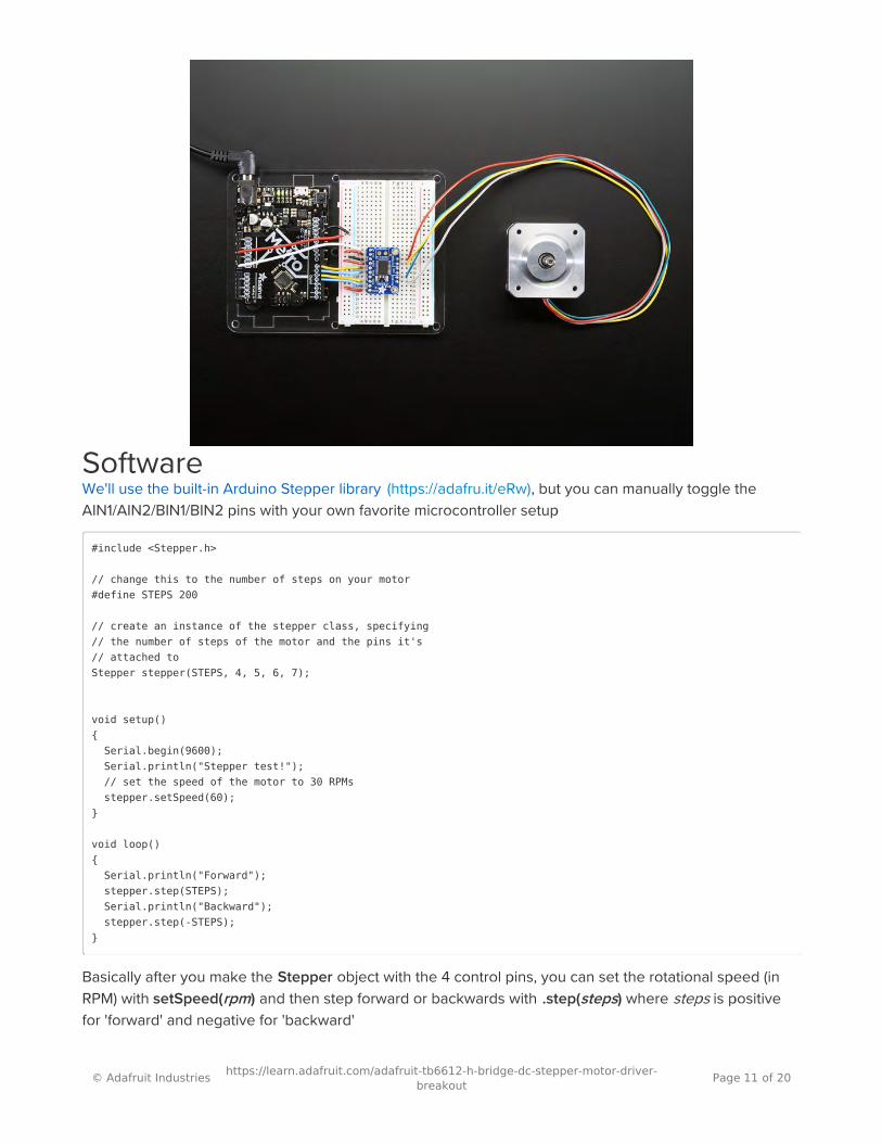
SoftwareWe'll use the built-in Arduino Stepper library (https://adafru.it/eRw), but you can manually toggle the
AIN1/AIN2/BIN1/BIN2 pins with your own favorite microcontroller setup
#include <Stepper.h>
// change this to the number of steps on your motor#define STEPS 200
// create an instance of the stepper class, specifying// the number of steps of the motor and the pins it's// attached toStepper stepper(STEPS, 4, 5, 6, 7);
void setup() Serial.begin(9600); Serial.println("Stepper test!"); // set the speed of the motor to 30 RPMs stepper.setSpeed(60);
void loop() Serial.println("Forward"); stepper.step(STEPS); Serial.println("Backward"); stepper.step(-STEPS);
Basically after you make the Stepper object with the 4 control pins, you can set the rotational speed (in
RPM) with setSpeed(rpm) and then step forward or backwards with .step(steps) where steps is positive
for 'forward' and negative for 'backward'
© Adafruit Industries https://learn.adafruit.com/adafruit-tb6612-h-bridge-dc-stepper-motor-driver-breakout Page 11 of 20

Appendix L
TB6612 driver
78

TB6612FNG
2012-11-01 1
Toshiba Bi-CD Integrated Circuit Silicon Monolithic
TB6612FNG Driver IC for Dual DC motor TB6612FNG is a driver IC for DC motor with output transistor in LD MOS structure with low ON-resistor. Two input signals, IN1 and IN2, can choose one of four modes such as CW, CCW, short brake, and stop mode.
Features • Power supply voltage: VM = 15 V(Max) • Output current: IOUT = 1.2 A(ave)/3.2 A (peak) • Output low ON resistor: 0.5Ω (upper+lower Typ. @ VM ≥ 5 V) • Standby (Power save) system • CW/CCW/short brake/stop function modes • Built-in thermal shutdown circuit and low voltage detecting circuit • Small faced package(SSOP24: 0.65 mm Lead pitch) * This product has a MOS structure and is sensitive to electrostatic discharge. When handling this product,
ensure that the environment is protected against electrostatic discharge by using an earth strap, a conductive mat and an ionizer. Ensure also that the ambient temperature and relative humidity are maintained at reasonable levels.
Weight: 0.14 g (typ.)

TB6612FNG
2012-11-01 2
Block Diagram
Pin Functions No. Pin Name I/O Function
1 AO1 2 AO1
O ch A output 1
3 PGND1 4 PGND1
― Power GND 1
5 AO2 6 AO2
O ch A output 2
7 BO2 8 BO2
O ch B output 2
9 PGND2 10 PGND2
― Power GND 2
11 BO1 12 BO1
O ch B output 1
13 VM2 14 VM3
― Motor supply
15 PWMB I ch B PWM input/200 kΩ pull-down at internal 16 BIN2 I ch B input 2/200 kΩ pull-down at internal 17 BIN1 I ch B input 1/200 kΩ pull-down at internal 18 GND ― Small signal GND 19 STBY I “L” = standby/200 kΩ pull-down at internal 20 Vcc ― Small signal supply 21 AIN1 I ch A input 1/200 kΩ pull-down at internal 22 AIN2 I ch A input 2/200 kΩ pull-down at internal 23 PWMA I ch A PWM input/200 kΩ pull-down at internal 24 VM1 ― Motor supply

TB6612FNG
2012-11-01 3
Absolute Maximum Ratings (Ta = 25°C)
Operating Range (Ta = -20 to 85°C)
Characteristics Symbol Rating Unit Remarks
VM 15 Supply voltage
VCC 6 V
Input voltage VIN -0.2 to 6 V IN1,IN2,STBY,PWM pins
Output voltage VOUT 15 V O1,O2 pins
IOUT 1.2 Per 1 ch
2 tw = 20 ms Continuous pulse, Duty ≤ 20% Output current IOUT (peak)
3.2
A
tw = 10 ms Single pulse
0.78 IC only
0.89 50 mm × 50 mm t = 1.6 mm Cu ≥ 40% in PCB mounting Power dissipation PD
1.36
W 76.2 mm × 114.3 mm t = 1.6 mm Cu ≥ 30% in PCB monting
Operating temperature Topr -20 to 85 °C
Storage temperature Tstg -55 to 150 °C
Characteristics Symbol Min Typ. Max Unit Remarks
VCC 2.7 3 5.5 V Supply voltage
VM 2.5 5 13.5 V ― ― 1.0 VM ≥ 4.5 V
Output current (H-SW) IOUT ― ― 0.4
A 4.5 V > VM ≥ 2.5 V Without PWM Operation
Switching frequency fPWM ― ― 100 kHz
入力端子; IN1,IN2,PWM,STBY
Vcc
GND
Input
Internalcircuit200kΩ
出力端子; O1,O2
VM
PGND
O1 O2
Input pin: Output pin: O1, O2
O1 O2
VM

TB6612FNG
2012-11-01 4
H-SW Control Function
Input Output
IN1 IN2 PWM STBY OUT1 OUT2 Mode
H H H/L H L L Short brake
H H L H CCW L H
L H L L Short brake
H H H L CW H L
L H L L Short brake
L L H H OFF
(High impedance) Stop
H/L H/L H/L L OFF
(High impedance) Standby
H-SW Operating Description ・To prevent penetrating current, dead time t2 and t4 is provided in switching to each mode in the IC.
VM VM VM
M
VM
GND
<ON> t5
M
VM
GND
<OFF> t4
M
GND
M
GND
<Short brake> t3
M
GND
<OFF> t2
<ON> t1
OUT2 OUT1 OUT1 OUT1
OUT1 OUT1
OUT2 OUT2
OUT2 OUT2
GND
VM
OUT1 Voltage wave
t1
t2
t3
t5
t4
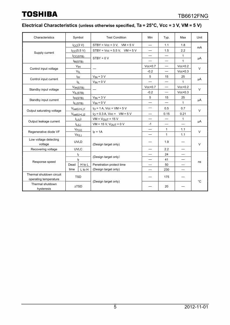
TB6612FNG
2012-11-01 5
Electrical Characteristics (unless otherwise specified, Ta = 25°C, Vcc = 3 V, VM = 5 V)
Characteristics Symbol Test Condition Min Typ. Max Unit
ICC(3 V) STBY = Vcc = 3 V, VM = 5 V ― 1.1 1.8
ICC(5.5 V) STBY = Vcc = 5.5 V, VM = 5 V ― 1.5 2.2 mA
ICC(STB) ― ― 1 Supply current
IM(STB) STBY = 0 V
― ― 1 μA
VIH Vcc×0.7 ― Vcc+0.2 Control input voltage
VIL ―
-0.2 ― Vcc×0.3 V
IIH VIN = 3 V 5 15 25 Control input current
IIL VIN = 0 V ― ― 1 μA
VIH(STB) Vcc×0.7 ― Vcc+0.2 Standby input voltage
VIL(STB) ―
-0.2 ― Vcc×0.3 V
IIH(STB) VIN = 3 V 5 15 25 Standby input current
IIL(STB) VIN = 0 V ― ― 1 μA
Vsat(U+L)1 IO = 1 A, Vcc = VM = 5 V ― 0.5 0.7 Output saturating voltage
Vsat(U+L)2 IO = 0.3 A, Vcc = VM = 5 V ― 0.15 0.21 V
IL(U) VM = VOUT = 15 V ― ― 1 Output leakage current
IL(L) VM = 15 V, VOUT = 0 V -1 ― ― μA
VF(U) ― 1 1.1 Regenerative diode VF
VF(L) IF = 1A
― 1 1.1 V
Low voltage detecting voltage
UVLD ― 1.9 ―
Recovering voltage UVLC (Design target only)
― 2.2 ― V
tr ― 24 ―
tf (Design target only)
― 41 ―
H to L ― 50 ― Response speed
Dead time L to H
Penetration protect time (Design target only) ― 230 ―
ns
Thermal shutdown circuit operating temperature
TSD ― 175 ―
Thermal shutdown hysteresis
∆TSD (Design target only)
― 20 ― °C
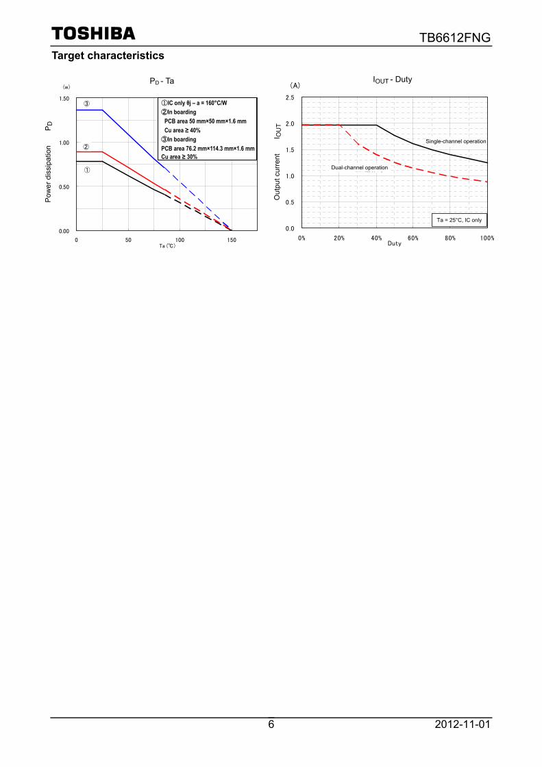
TB6612FNG
2012-11-01 6
Target characteristics
PD - Ta
0.00
0.50
1.00
1.50
0 50 100 150Ta ()
(w)
①
②
①IC単体θj-a=160/W②基板実装時
PCB面積 50×50×1.6mm
Cu箔面積≧40%
③基板実装時
PCB面積 76.2×114.3×1.6mm
Cu箔面積≧30%
③ ①IC only θj – a = 160°C/W ②In boarding PCB area 50 mm×50 mm×1.6 mm Cu area ≥ 40% ③In boarding PCB area 76.2 mm×114.3 mm×1.6 mm Cu area ≥ 30%
Pow
er d
issi
patio
n P D
PD - Ta
Ta = 25°C, IC only
1 ch driving
2 ch driving
Iout - Duty
0.0
0.5
1.0
1.5
2.0
2.5
0% 20% 40% 60% 80% 100%Duty
(A)
2ch動作時
1ch動作時
Ta=25,IC単体
Out
put c
urre
nt I O
UT
IOUT - Duty
Dual-channel operation
Single-channel operation
Ta = 25°C, IC only
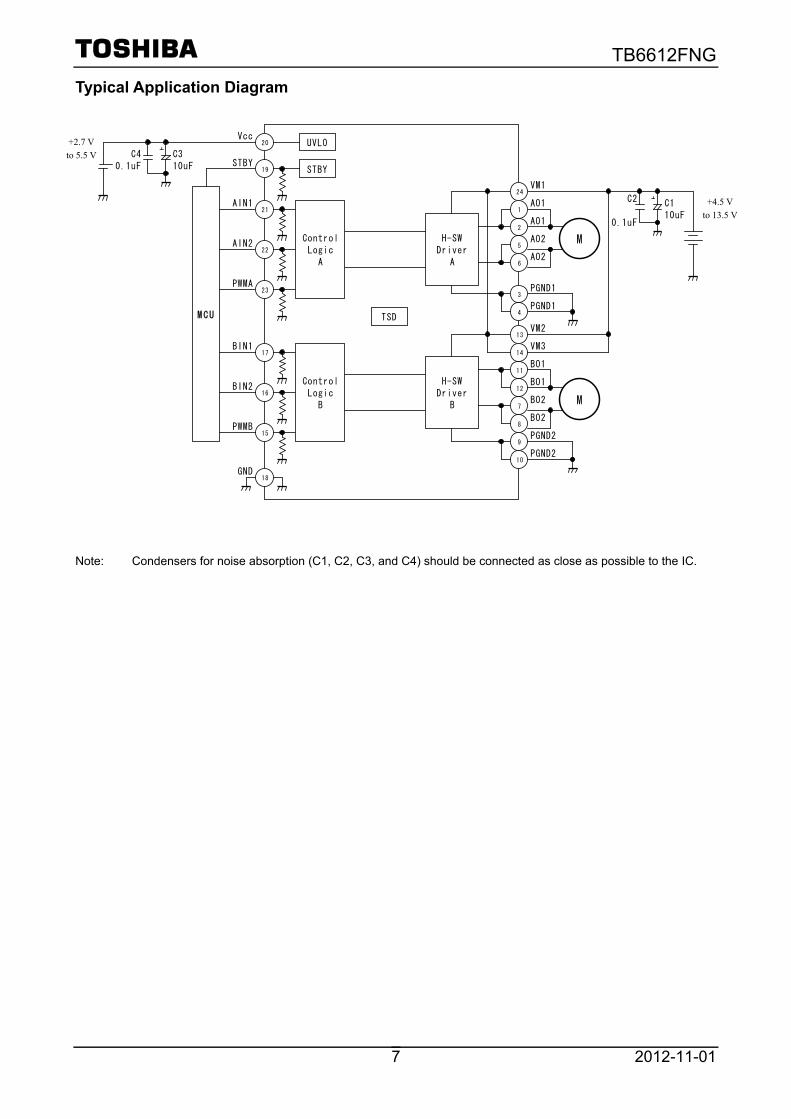
TB6612FNG
2012-11-01 7
Typical Application Diagram Note: Condensers for noise absorption (C1, C2, C3, and C4) should be connected as close as possible to the IC.
+4.5V~13.5V
+ C110uF
C2
0.1uF
M
M CU
STBY
AIN1
AIN2
PWMA
H-SWDriver
A
18
TSD
Vcc
GND
2AO1
24VM1
ControlLogic
A
20
21
22
23
19
3PGND1
BIN1
BIN2
PWMB
ControlLogic
B
17
16
15
STBY
UVLO
4PGND1
1AO1
6AO2
5AO2
H-SWDriver
B
11BO1
13VM2
9PGND2
10PGND2
12BO1
7BO2
8BO2
14VM3
M
+2.7V~5.5V
+ C310uF
C40.1uF
+2.7 V to 5.5 V
+4.5 Vto 13.5 V

TB6612FNG
2012-11-01 8
Package Dimennsions
Weght: 0.14 g (typ)
Detail of a terminal

TB6612FNG
2012-11-01 9
Notes on Contents 1. Block Diagrams
Some of the functional blocks, circuits, or constants in the block diagram may be omitted or simplified for explanatory purposes.
2. Equivalent Circuits
The equivalent circuit diagrams may be simplified or some parts of them may be omitted for explanatory purposes.
3. Timing Charts
Timing charts may be simplified for explanatory purposes. 4. Application Circuits
The application circuits shown in this document are provided for reference purposes only. Thorough evaluation is required, especially at the mass production design stage. Toshiba does not grant any license to any industrial property rights by providing these examples of application circuits.
5. Test Circuits
Components in the test circuits are used only to obtain and confirm the device characteristics. These components and circuits are not guaranteed to prevent malfunction or failure from occurring in the application equipment.
IC Usage Considerations
Notes on handling of ICs [1] The absolute maximum ratings of a semiconductor device are a set of ratings that must not be
exceeded, even for a moment. Do not exceed any of these ratings. Exceeding the rating(s) may cause the device breakdown, damage or deterioration, and may result injury by explosion or combustion.
[2] Use an appropriate power supply fuse to ensure that a large current does not continuously flow in
case of over current and/or IC failure. The IC will fully break down when used under conditions that exceed its absolute maximum ratings, when the wiring is routed improperly or when an abnormal pulse noise occurs from the wiring or load, causing a large current to continuously flow and the breakdown can lead smoke or ignition. To minimize the effects of the flow of a large current in case of breakdown, appropriate settings, such as fuse capacity, fusing time and insertion circuit location, are required.
[3] If your design includes an inductive load such as a motor coil, incorporate a protection circuit into
the design to prevent device malfunction or breakdown caused by the current resulting from the inrush current at power ON or the negative current resulting from the back electromotive force at power OFF. IC breakdown may cause injury, smoke or ignition. Use a stable power supply with ICs with built-in protection functions. If the power supply is unstable, the protection function may not operate, causing IC breakdown. IC breakdown may cause injury, smoke or ignition.
[4] Do not insert devices in the wrong orientation or incorrectly. Make sure that the positive and negative terminals of power supplies are connected properly. Otherwise, the current or power consumption may exceed the absolute maximum rating, and exceeding the rating(s) may cause the device breakdown, damage or deterioration, and may result injury by explosion or combustion. In addition, do not use any device that is applied the current with inserting in the wrong orientation or incorrectly even just one time.

TB6612FNG
2012-11-01 10
Points to remember on handling of ICs (1) Thermal Shutdown Circuit
Thermal shutdown circuits do not necessarily protect ICs under all circumstances. If the thermal shutdown circuits operate against the over temperature, clear the heat generation status immediately. Depending on the method of use and usage conditions, such as exceeding absolute maximum ratings can cause the thermal shutdown circuit to not operate properly or IC breakdown before operation.
(2) Heat Radiation Design
In using an IC with large current flow such as power amp, regulator or driver, please design the device so that heat is appropriately radiated, not to exceed the specified junction temperature (Tj) at any time and condition. These ICs generate heat even during normal use. An inadequate IC heat radiation design can lead to decrease in IC life, deterioration of IC characteristics or IC breakdown. In addition, please design the device taking into considerate the effect of IC heat radiation with peripheral components.
(3) Back-EMF
When a motor rotates in the reverse direction, stops or slows down abruptly, a current flow back to the motor’s power supply due to the effect of back-EMF. If the current sink capability of the power supply is small, the device’s motor power supply and output pins might be exposed to conditions beyond absolute maximum ratings. To avoid this problem, take the effect of back-EMF into consideration in system design.
TB6612FNG
2012-11-01 11
RESTRICTIONS ON PRODUCT USE • Toshiba Corporation, and its subsidiaries and affiliates (collectively "TOSHIBA"), reserve the right to make changes to the information
in this document, and related hardware, software and systems (collectively "Product") without notice.
• This document and any information herein may not be reproduced without prior written permission from TOSHIBA. Even with TOSHIBA's written permission, reproduction is permissible only if reproduction is without alteration/omission.
• Though TOSHIBA works continually to improve Product's quality and reliability, Product can malfunction or fail. Customers are responsible for complying with safety standards and for providing adequate designs and safeguards for their hardware, software and systems which minimize risk and avoid situations in which a malfunction or failure of Product could cause loss of human life, bodily injury or damage to property, including data loss or corruption. Before customers use the Product, create designs including the Product, or incorporate the Product into their own applications, customers must also refer to and comply with (a) the latest versions of all relevant TOSHIBA information, including without limitation, this document, the specifications, the data sheets and application notes for Product and the precautions and conditions set forth in the "TOSHIBA Semiconductor Reliability Handbook" and (b) the instructions for the application with which the Product will be used with or for. Customers are solely responsible for all aspects of their own product design or applications, including but not limited to (a) determining the appropriateness of the use of this Product in such design or applications; (b) evaluating and determining the applicability of any information contained in this document, or in charts, diagrams, programs, algorithms, sample application circuits, or any other referenced documents; and (c) validating all operating parameters for such designs and applications. TOSHIBA ASSUMES NO LIABILITY FOR CUSTOMERS' PRODUCT DESIGN OR APPLICATIONS.
• PRODUCT IS NEITHER INTENDED NOR WARRANTED FOR USE IN EQUIPMENTS OR SYSTEMS THAT REQUIRE EXTRAORDINARILY HIGH LEVELS OF QUALITY AND/OR RELIABILITY, AND/OR A MALFUNCTION OR FAILURE OF WHICH MAY CAUSE LOSS OF HUMAN LIFE, BODILY INJURY, SERIOUS PROPERTY DAMAGE AND/OR SERIOUS PUBLIC IMPACT ("UNINTENDED USE"). Except for specific applications as expressly stated in this document, Unintended Use includes, without limitation, equipment used in nuclear facilities, equipment used in the aerospace industry, medical equipment, equipment used for automobiles, trains, ships and other transportation, traffic signaling equipment, equipment used to control combustions or explosions, safety devices, elevators and escalators, devices related to electric power, and equipment used in finance-related fields. IF YOU USE PRODUCT FOR UNINTENDED USE, TOSHIBA ASSUMES NO LIABILITY FOR PRODUCT. For details, please contact your TOSHIBA sales representative.
• Do not disassemble, analyze, reverse-engineer, alter, modify, translate or copy Product, whether in whole or in part.
• Product shall not be used for or incorporated into any products or systems whose manufacture, use, or sale is prohibited under any applicable laws or regulations.
• The information contained herein is presented only as guidance for Product use. No responsibility is assumed by TOSHIBA for any infringement of patents or any other intellectual property rights of third parties that may result from the use of Product. No license to any intellectual property right is granted by this document, whether express or implied, by estoppel or otherwise.
• ABSENT A WRITTEN SIGNED AGREEMENT, EXCEPT AS PROVIDED IN THE RELEVANT TERMS AND CONDITIONS OF SALE FOR PRODUCT, AND TO THE MAXIMUM EXTENT ALLOWABLE BY LAW, TOSHIBA (1) ASSUMES NO LIABILITY WHATSOEVER, INCLUDING WITHOUT LIMITATION, INDIRECT, CONSEQUENTIAL, SPECIAL, OR INCIDENTAL DAMAGES OR LOSS, INCLUDING WITHOUT LIMITATION, LOSS OF PROFITS, LOSS OF OPPORTUNITIES, BUSINESS INTERRUPTION AND LOSS OF DATA, AND (2) DISCLAIMS ANY AND ALL EXPRESS OR IMPLIED WARRANTIES AND CONDITIONS RELATED TO SALE, USE OF PRODUCT, OR INFORMATION, INCLUDING WARRANTIES OR CONDITIONS OF MERCHANTABILITY, FITNESS FOR A PARTICULAR PURPOSE, ACCURACY OF INFORMATION, OR NONINFRINGEMENT.
• Do not use or otherwise make available Product or related software or technology for any military purposes, including without limitation, for the design, development, use, stockpiling or manufacturing of nuclear, chemical, or biological weapons or missile technology products (mass destruction weapons). Product and related software and technology may be controlled under the applicable export laws and regulations including, without limitation, the Japanese Foreign Exchange and Foreign Trade Law and the U.S. Export Administration Regulations. Export and re-export of Product or related software or technology are strictly prohibited except in compliance with all applicable export laws and regulations.
• Please contact your TOSHIBA sales representative for details as to environmental matters such as the RoHS compatibility of Product. Please use Product in compliance with all applicable laws and regulations that regulate the inclusion or use of controlled substances, including without limitation, the EU RoHS Directive. TOSHIBA ASSUMES NO LIABILITY FOR DAMAGES OR LOSSES OCCURRING AS A RESULT OF NONCOMPLIANCE WITH APPLICABLE LAWS AND REGULATIONS.

Appendix M
Set screw hub - 5mm Bore
Figure M.1. Set screw hub datasheet.
90
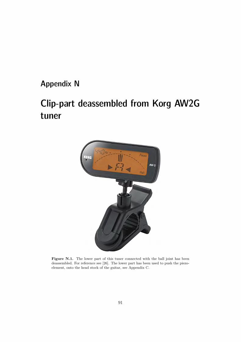
Appendix N
Clip-part deassembled from Korg AW2Gtuner
Figure N.1. The lower part of this tuner connected with the ball joint has beendeassembled. For reference see [26]. The lower part has been used to push the piezo-element, onto the head stock of the guitar, see Appendix C.
91

Appendix O
Pitchclip 2 Clip-on tuner
Scale 12-note equal temperamentDetection range (sine wave) AO (27.5 Hz) - C8 (4186 Hz)
Detection Accuracy +/- 1 centPower Supply CR2032 lithium battery x 1Battery Life Approximately 24 hours (A4 input)
Dimensions (W x D x H) 52 x 24 x 34 mmWeight 17g (including batteries)
Figure O.1. This clip-on tuner model was used to calibrate our the piezo element’sfrequency detection [27] .
92

TRITA TRITA-ITM-EX 2021:24
www.kth.se
Related Documents