Pierre Gélat Pierre Gélat National Physical Laboratory National Physical Laboratory 3 April 2003 3 April 2003 Developments in Acoustic Developments in Acoustic Emission at the UK’s Emission at the UK’s National Physical National Physical Laboratory Laboratory

Pierre Gélat National Physical Laboratory 3 April 2003 Developments in Acoustic Emission at the UK’s National Physical Laboratory.
Dec 20, 2015
Welcome message from author
This document is posted to help you gain knowledge. Please leave a comment to let me know what you think about it! Share it to your friends and learn new things together.
Transcript

Pierre GélatPierre Gélat
National Physical LaboratoryNational Physical Laboratory
3 April 20033 April 2003
Developments in Acoustic Developments in Acoustic Emission at the UK’s National Emission at the UK’s National Physical LaboratoryPhysical Laboratory
The Finite Element MethodThe Finite Element Method
The FE method is a numerical method to solve arbitrary PDEs The FE method is a numerical method to solve arbitrary PDEs
The method consists of approximating the structure in small The method consists of approximating the structure in small domain portions called finite elementsdomain portions called finite elements
Each element has a set of material properties associated with it Each element has a set of material properties associated with it (Young’s modulus, material density, Poisson’s ratio, etc.)(Young’s modulus, material density, Poisson’s ratio, etc.)
A set of output quantities (e.g. displacement) can be obtained A set of output quantities (e.g. displacement) can be obtained for given forcing/boundary conditionsfor given forcing/boundary conditions
http://www.npl.co.uk/npl/acousticshttp://www.npl.co.uk/npl/acoustics
Axisymetric and Three Dimensional Axisymetric and Three Dimensional Transducer ModellingTransducer Modelling
Use of PAFEC 8.6 Vibroacoustics software (soon to be upgraded to 8.8) Use of PAFEC 8.6 Vibroacoustics software (soon to be upgraded to 8.8) used for modelling the behaviour of ultrasonic and audio-range transducer, used for modelling the behaviour of ultrasonic and audio-range transducer, with fluid loading or in vacuum, for both continuous and transient excitationwith fluid loading or in vacuum, for both continuous and transient excitation
Allows the coupling of vibrating structures to the modelling of finite and Allows the coupling of vibrating structures to the modelling of finite and infinite regions of fluid (boundary elements, wave envelope elements)infinite regions of fluid (boundary elements, wave envelope elements)
Piezoelectric elements can be defined Piezoelectric elements can be defined
PAFEC’s mathematicians are working with NPL both to extend the PAFEC’s mathematicians are working with NPL both to extend the functionality of the software and to provide NPL with bespoke software to functionality of the software and to provide NPL with bespoke software to tackle specific modelling problemstackle specific modelling problems
Quantities routinely obtained from PAFEC include: acoustic pressure, Quantities routinely obtained from PAFEC include: acoustic pressure, structural displacement and electrical impedance structural displacement and electrical impedance
Sensitivity analysis and optimisation capabilities Sensitivity analysis and optimisation capabilities
http://www.npl.co.uk/npl/acousticshttp://www.npl.co.uk/npl/acoustics
Sensor Modelling Using the Finite Element MethodSensor Modelling Using the Finite Element Method
Understanding the dynamics of piezoelectric sensorUnderstanding the dynamics of piezoelectric sensor
Investigating the effect of variations in design on overall Investigating the effect of variations in design on overall sensitivitysensitivity
Designing novel sensor configurationsDesigning novel sensor configurations
Sensitivity analysis and optimisation (sensitivity Sensitivity analysis and optimisation (sensitivity vsvs. . bandwidth)bandwidth)
http://www.npl.co.uk/npl/acousticshttp://www.npl.co.uk/npl/acoustics
AE sensor modellingAE sensor modelling
Sensor is assumed to be axisymmetricSensor is assumed to be axisymmetric
Piezoelectric material is PZT5-APiezoelectric material is PZT5-A
Apply unit voltage across PZT5-A between 0.1 MHz and 1MHzApply unit voltage across PZT5-A between 0.1 MHz and 1MHz
Obtain electrical impedanceObtain electrical impedance
http://www.npl.co.uk/npl/acousticshttp://www.npl.co.uk/npl/acoustics
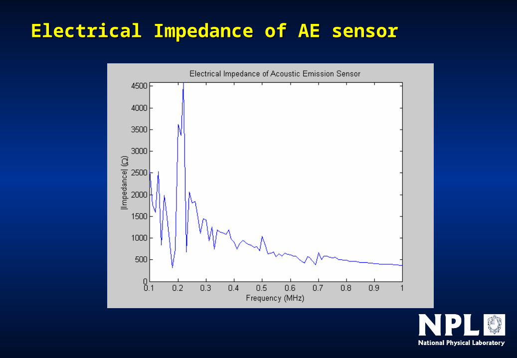
Electrical Impedance of AE sensorElectrical Impedance of AE sensor

Modelling of AE reference facilityModelling of AE reference facility
Aim is to develop a methodology to model a simple AE system from the Aim is to develop a methodology to model a simple AE system from the electrical excitation of the reference transducer to the electrical output of the electrical excitation of the reference transducer to the electrical output of the sensorsensor
Requires the combination of more than one techniqueRequires the combination of more than one technique
- one to model the transducer and sensorone to model the transducer and sensor
- the other to model the stress wave propagation in the mediumthe other to model the stress wave propagation in the medium
NPL’s Finite Element (FE) method used toNPL’s Finite Element (FE) method used to
- predict displacement output of transducer for a given electrical inputpredict displacement output of transducer for a given electrical input
- predict electrical response of sensor for a given displacement at its facepredict electrical response of sensor for a given displacement at its face
Fraunhofer’s Finite Difference/Integral (EFIT) method used toFraunhofer’s Finite Difference/Integral (EFIT) method used to
- predict displacement as a function of time at a given point in an elastic predict displacement as a function of time at a given point in an elastic mediummedium
http://www.npl.co.uk/npl/acousticshttp://www.npl.co.uk/npl/acoustics

Experimental arrangementExperimental arrangement
• The reflective The reflective coating is coating is Aluminium or Aluminium or ChromiumChromium
• The displacement The displacement equivalent noise equivalent noise floor of the floor of the interferometer is interferometer is around 3.5 pmaround 3.5 pmRMSRMS
1)1) Out-of-plane displacement history of surface measured using Out-of-plane displacement history of surface measured using interferometerinterferometer
2)2) Repeated with sensor coupled in place of interferometerRepeated with sensor coupled in place of interferometer

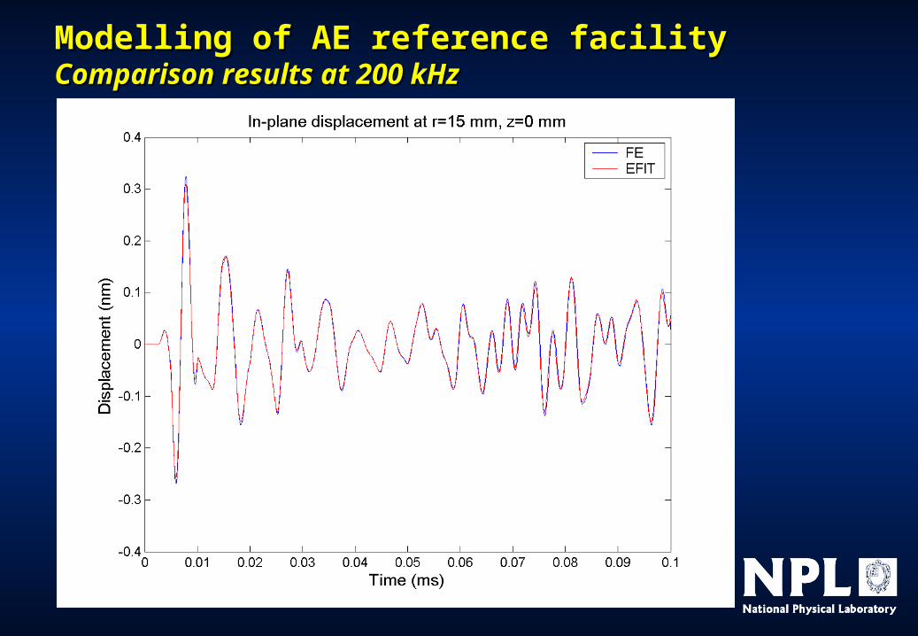
Modelling of AE reference facilityModelling of AE reference facilityComparison of NPL’s FE and Fraunhofer’s EFIT methodComparison of NPL’s FE and Fraunhofer’s EFIT method
Comparison performed using a simple Comparison performed using a simple problem for validationproblem for validation
- point displacement excitationpoint displacement excitation
- small cylindrical glass block allows small cylindrical glass block allows treatment as an axisymmetric problemtreatment as an axisymmetric problem
- displacements compared at chosen displacements compared at chosen pointspoints
Peter D. Theobald:
Peter D. Theobald:
. .
Force Force f = A sin (2f = A sin (2ft) . B sin (ft) . B sin (ft)ft) excited excited at at r = 0r = 0, , z = 0z = 0
http://www.npl.co.uk/npl/acousticshttp://www.npl.co.uk/npl/acoustics

Reference source - Reference source - Finite Element modelling of conical transducer

Reference source - Reference source - Finite Element modelling of conical transducer

Modelling of AE reference facilityModelling of AE reference facilityComparison results at 200 kHzComparison results at 200 kHz
Modelling of AE reference facilityModelling of AE reference facilityComparison results at 200 kHzComparison results at 200 kHz

Modelling of AE reference facilityModelling of AE reference facilityComparison results at 200 kHzComparison results at 200 kHz

Modelling of AE reference facility - Modelling of AE reference facility - ConclusionsConclusions
Validation is complete and shows good comparison between Validation is complete and shows good comparison between techniquestechniques
Work is now progressing on the modelling of a complete system Work is now progressing on the modelling of a complete system comprising of source transducer, glass cylinder and sensorcomprising of source transducer, glass cylinder and sensor
If successful this should produce a complete transfer function for the If successful this should produce a complete transfer function for the AE system for each wave mode received at the sensorAE system for each wave mode received at the sensor
Next stage of work is to model the NPL test facilityNext stage of work is to model the NPL test facility
- would provide more information for the calibration of sensorswould provide more information for the calibration of sensors
- could be combined with a calibrated reference source to provide system could be combined with a calibrated reference source to provide system calibrationcalibration
Related Documents