Project Number: YR-RB01 picoBrew: Automated Home Brew A Major Qualifying Project Report: submitted to the faculty of the WORCESTER POLYTECHNIC INSTITUTE in partial fulfillment of the requirements for the Degree of Bachelor of Science By _________________________________ Peter Bertoli _________________________________ Daniel Flavin _________________________________ Christopher Moniz _________________________________ Sean Seymour Date: April 30, 2009 Approved: _________________________________ Professor Yiming Rong, Major Advisor

Welcome message from author
This document is posted to help you gain knowledge. Please leave a comment to let me know what you think about it! Share it to your friends and learn new things together.
Transcript
Project Number: YR-RB01
picoBrew: Automated Home Brew
A Major Qualifying Project Report:
submitted to the faculty of the
WORCESTER POLYTECHNIC INSTITUTE
in partial fulfillment of the requirements for the
Degree of Bachelor of Science
By
_________________________________
Peter Bertoli
_________________________________
Daniel Flavin
_________________________________
Christopher Moniz
_________________________________
Sean Seymour
Date: April 30, 2009
Approved:
_________________________________
Professor Yiming Rong, Major Advisor
Abstract
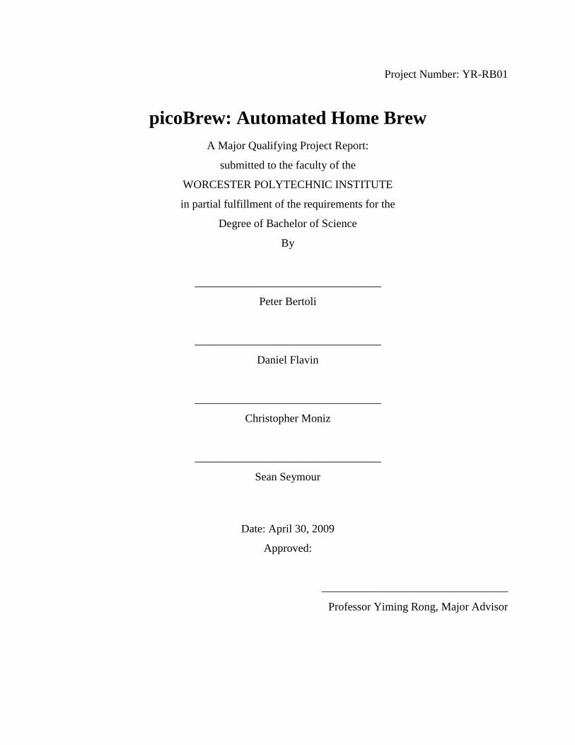
The picoBrew project determined the marketable requirements of a small-scale
automated beer brewing system. Techniques from industrial robotics were applied to the basic
home brew cycle, resulting in a prototype design which could be easily controlled as well as
manufactured. The prototype design focused on repeatability and ease of cleaning, two of the
major requirements as determined from market studies. The prototype was capable of
independently performing the heating, ingredient handling, and cooling cycles required to make
beer.
Acknowledgements
We would like to thank:
Yiming (Kevin) Rong (Project Advisor)
Chuck (McNamara Fabricating Co Inc)
Torbjorn S. Bergstrom (WPI)
Greg Cole
Joe Zhu (WPI)
Chickery Kasouf (WPI)
Neil Bryer (www.wombatcomic.com)
This project would not have been successfully completed without their support.
Table of Contents
List of Figures ................................................................................................................................. i List of Tables ................................................................................................................................... i 1 Introduction ............................................................................................................................. 1
2 Background ............................................................................................................................. 3 2.1 Brewing ............................................................................................................................ 3
2.1.1 Ingredients................................................................................................................. 3 2.1.2 The Brewing Process ................................................................................................ 5
2.2 Challenges in Automation ................................................................................................ 7
2.3 Similar Products ............................................................................................................... 8 3 Methodology ......................................................................................................................... 10
3.1 Computer Aided Design (CAD) Modeling .................................................................... 10 3.2 Computer Aided Manufacture (CAM) ........................................................................... 11 3.3 Physical Build ................................................................................................................ 12 3.4 Control Assembly ........................................................................................................... 12
4 Results ................................................................................................................................... 14 4.1 System Options .............................................................................................................. 14
4.1.1 Boiling Vessel ......................................................................................................... 14 4.1.2 Heating Element...................................................................................................... 15 4.1.3 Cooling Methods ..................................................................................................... 16
4.1.4 Ingredient Handling ................................................................................................ 17 4.1.5 Control System........................................................................................................ 19
4.2 Final System Design....................................................................................................... 21 4.2.1 Mechanical System ................................................................................................. 21
4.2.2 Control System........................................................................................................ 25 4.3 System Performance ....................................................................................................... 29
5 Conclusion and Recommendations ....................................................................................... 31
6 Business Plan ........................................................................................................................ 32 8 Appendices ............................................................................................................................ 37
8.1 Appendix A - Overall thermodynamic equations: ......................................................... 37 8.2 Appendix B – Recipe Research ...................................................................................... 39 8.3 Appendix C – CuBloc Port Listing ................................................................................ 43
8.4 Appendix D – Schematic Diagrams ............................................................................... 44 8.5 Appendix E – Calibration Data ...................................................................................... 47 8.6 Appendix F – Menu Flow Chart .................................................................................... 49 8.7 Appendix G – Survey Information ................................................................................. 51
8.9 Appendix H – Bill of Materials ...................................................................................... 54 8.10 Appendix I – Labor Costs .............................................................................................. 57 8.11 Appendix J – Poster........................................................................................................ 58
List of Figures
Figure 1: The Home Brew Process ................................................................................................. 1
Figure 3 - CAD model of Hops Handling Cell ............................................................................. 10
Figure 2 - Standard Design Cycle ................................................................................................. 10
Figure 4 - Example of CAM for welding fixture .......................................................................... 11
Figure 5 - Welding Fixture Mounted on Frame ............................................................................ 12
Figure 6: Software Flow Chart ..................................................................................................... 13
Figure 7 - Thermoydynamic Representation of System ............................................................... 23
Figure 8 – Prototype...................................................................................................................... 24
Figure 9: Final System Schematic ................................................................................................ 27
Figure 10: Control System Block Diagram .................................................................................. 28
List of Tables
Table 1 - Boiling Vessel Advantages vs. Disadvantages .............................................................. 14
Table 2 – Heating Element Advantages vs. Disadvantages .......................................................... 15
Table 3 - Cooling Option Advantages vs. Disadvantages ............................................................ 16
Table 4 – Water vs. Refrigerant Cooling Systems ........................................................................ 17
Table 5 – Steep System Drive Options ......................................................................................... 18
Table 6 – Malt Handling Drive Options ....................................................................................... 18
Table 7 – Steep System Drive Options ......................................................................................... 19
Table 8 – Controller Options ........................................................................................................ 20
Table 9 – Display Advantages vs. Disadvantages ........................................................................ 20
Table 10 – Temperature Sensor Advantages vs. Disadvantages .................................................. 21
1
1 Introduction
The home brewing of beer has become an increasingly popular pastime in the United
States since being federally legalized in 19781. Currently, there are an estimated one and a
quarter million home brewers in the US and Canada, brewing some 36 million bottles of beer a
year2. These individuals support a thriving industry of home brew suppliers and associations.
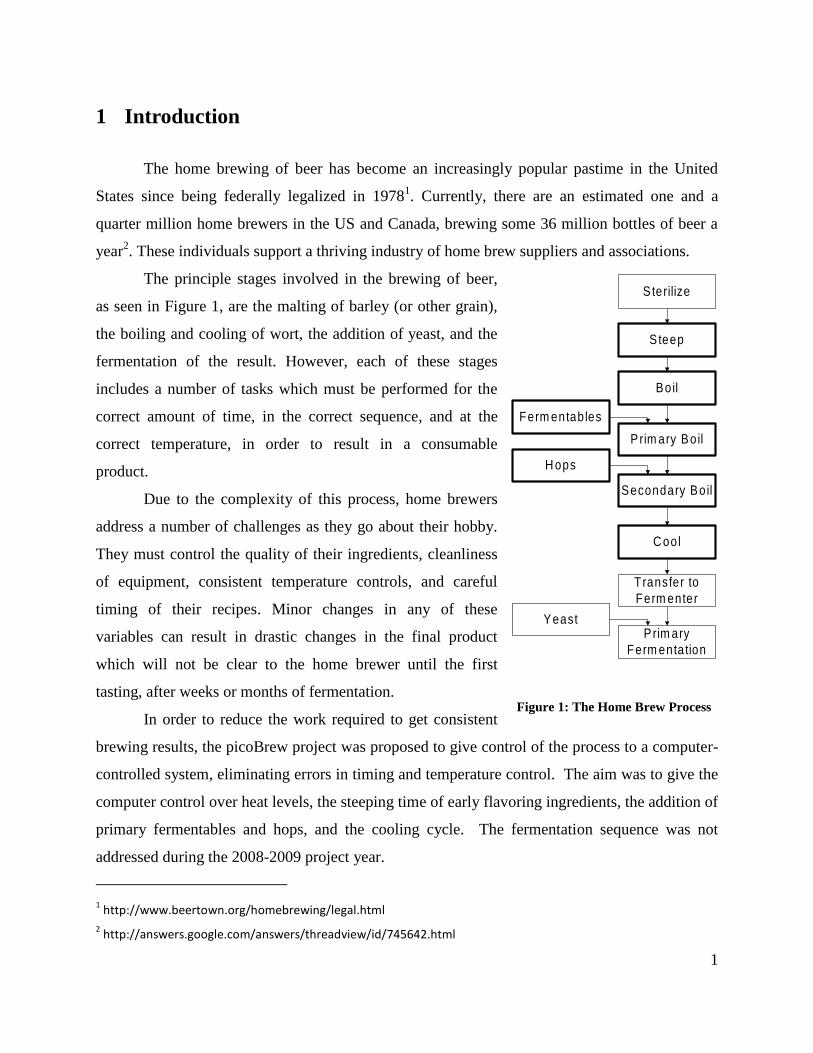
The principle stages involved in the brewing of beer,
as seen in Figure 1, are the malting of barley (or other grain),
the boiling and cooling of wort, the addition of yeast, and the
fermentation of the result. However, each of these stages
includes a number of tasks which must be performed for the
correct amount of time, in the correct sequence, and at the
correct temperature, in order to result in a consumable
product.
Due to the complexity of this process, home brewers
address a number of challenges as they go about their hobby.
They must control the quality of their ingredients, cleanliness
of equipment, consistent temperature controls, and careful
timing of their recipes. Minor changes in any of these
variables can result in drastic changes in the final product
which will not be clear to the home brewer until the first
tasting, after weeks or months of fermentation.
In order to reduce the work required to get consistent
brewing results, the picoBrew project was proposed to give control of the process to a computer-
controlled system, eliminating errors in timing and temperature control. The aim was to give the
computer control over heat levels, the steeping time of early flavoring ingredients, the addition of
primary fermentables and hops, and the cooling cycle. The fermentation sequence was not
addressed during the 2008-2009 project year.
1 http://www.beertown.org/homebrewing/legal.html
2 http://answers.google.com/answers/threadview/id/745642.html
Sterilize
S teep
Boil
Ferm entables
Prim ary Boil
H ops
Secondary Boil
C ool
Transfer to
Ferm enter
YeastP rim ary
Ferm entation
Figure 1: The Home Brew Process

2
The final goal of the picoBrew project was to develop a prototype of a commercially
viable automated homebrew system aimed at both novice and veteran home brewers who want a
greater freedom to experiment with ingredients and recipes, leaving the procedural concerns to
the computer.
3
2 Background
The brewing process is an exceptionally complex system. While wine is simply fermented
grape juice, beer requires many more ingredients, processed in a very specific fashion. In order
to understand the automation of brewing, a complete understanding of these ingredients and
steps is required.
2.1 Brewing
Brewing is the name given to the process of creating beer from raw ingredients. The
process of brewing consists of three major cycles; boiling, cooling, and fermentation. Each of
these cycles alters the characteristics of the beer by the chemical processes that occur during the
cycle.
2.1.1 Ingredients
There are four primary ingredients in the brewing of beer: water, malts, hops and yeast.
Characteristics of malt and hops are particularly sensitive to small changes in the brewing
process, and thus were the primary focus of the picoBrew system.
2.1.1.1 Water
The water used in the brewing process may change the taste of the beer, as varied
mineral content exists from different water sources. Many brewers choose to use filtered
water to eliminate these minerals; however, others choose not to, seeking to use the
minerals to add distinctive additional flavor to their beer.
2.1.1.2 Malts
The sugars that drive fermentation come from the malt extract. In the malting
process, barley is soaked in water then drained to initiate the germination process.
Germination activates enzymes within the barley which convert starch and proteins into
sugars that would subsequently be used by the plant. Once the seed starts to sprout, it is
4
dried quickly to halt the germination process. At this point, it is shipped to commercial
breweries, where it is crushed and soaked in hot water to restart and accelerate the
enzyme activity to convert the remaining starches to sugars. The malt extract used by
most home brewers is made by dehydrating the resulting sugar solution, which is then
packaged for sale as either a powder or syrup with approximately 20% water content3.
2.1.1.3 Hops
Hops are divided into one of two categories, bittering hops and aroma hops. They
are characterized by their bitter flavor which is used to balance the sugars of malts in
beer. They are classified by weight percent alpha acid resin within the hop cones.
Bittering hops average around 10% by weight, while aroma hops only average 5% by
weight4. The higher concentration of alpha acid resin in bittering hops allow for the
release of flavor over a longer period of time.
2.1.1.4 Yeast
The yeast chosen to ferment the wort has a substantial influence on the finished
beer. Different strains of yeast are able to survive in environments of varying
temperatures and levels of alcohol. Therefore, yeast can be chosen based on the amount
of sugar in the beer which the brewer wants converted to alcohol, as well as the
fermentation environment. Different strains of yeast may also give the beer fruity or
nutty flavors.
3 Palmer, J. (1999). What is Malt. Retrieved December 14, 2008, from How to Brew:
http://www.howtobrew.com/section1/chapter3.html
4 Palmer, J. (1999). Hops: How Are They Used. Retrieved December 14, 2008, from How to Brew:
http://www.howtobrew.com/section1/chapter5-1.html
5
2.1.2 The Brewing Process
The brewing process starts with a vat of water. Flavoring grains are steeped in the water at
a sub-boiling temperature then removed. Malt is added once the water reaches a boil, and hops
are added at various points throughout the boiling cycle. As the mixture boils, flavors develop.
However, some sulfur-based compounds form which must evaporate or they could adversely
affect the flavor.
2.1.2.1 Steeping Cycle
The steep cycle adds sugars, flavors, and “mouth feel” to the beer, using a variety
of cracked grains. These grains serve as the foundation for various flavors and are usually
held at a given temperature, from 140-170 °F, for 30 to 90 minutes, and then removed.
The water is then brought to a boil for the malt addition stage.
2.1.2.2 Malt Addition
The addition of malts to the boiling water results in wort, the unfermented
precursor to beer. The malts add a sweet flavor and the sugars needed for fermentation to
the beer. Most recipes call for the addition of malts at the start of the boil cycle, to allow
the malts to fully dissolve in the water; however, others call for malts to be added at
different intervals during the boiling cycle to impart a stronger sweet flavor to the wort
before the boiling is complete.
Upon addition of malt extract, foaming occurs within the wort. This foam is the
malt protein coagulating due to the heat and rolling motion of the boil. Boil over may
occur when this foam expands over the edge of the pot and begins to spill out. This can
be prevented by regularly mixing the wort in order to break up the coagulated proteins5.
5 Palmer, J. (1999). The "Hot Break". Retrieved December 14, 2008, from How to Brew:
http://www.howtobrew.com/section1/chapter7-2.html
6
2.1.2.3 Hop Addition
Hops are added at various intervals to impart specific flavors to the wort. These
additions to the boil cycle fall into three categories: bittering, flavoring and finishing,
each of which is a combination of specific hops with specific timing cycles.
Bittering hops are added at the beginning of the boil cycle in order to allow for
full release of the alpha acid resin as it isomerizes. The bittering boil time is usually
between 45 and 90 minutes. An increase in the boil time will improve the isomerization,
by approximately 5% as time increases from 45 to 90 minutes. Further heating will result
in boiling off aromatic oils, reducing aroma and flavor.
Flavoring hops are added partway through the boil cycle to reach a compromise
between bittering and aroma characteristics. While less alpha acid resin will isomerize,
creating less bitter flavor, less of the aromatic oils will evaporate, leaving the wort with a
stronger aroma at the end of the boil cycle.
Finishing hops are added at the end of the boil cycle. These hops have a low
alpha acid concentration but are higher in aromatic oils. By adding them at the end of the
cycle, most of the aromatic oils remain in the wort adding a stronger aroma
characteristic6.
2.1.2.4 Cooling
Cooling the wort quickly is important for sanitation and flavor reasons. While the
wort is still hot it is protected from bacterial formation by the elevated temperatures. As
the wort cools, bacteria are able to colonize the liquid, negatively impacting the flavor
throughout the fermentation process. By rapidly cooling the wort, it can be transferred
into the sterilized fermentation container quickly, reducing the chance for bacterial
contamination7.
6 Palmer, J. (1999). Hops: How Are They Used. Retrieved December 14, 2008, from How to Brew:
http://www.howtobrew.com/section1/chapter5-1.html
7 Palmer, J. (1999). Cooling the Wort. Retrieved December 14, 2008, from How to Brew:
http://www.howtobrew.com/section1/chapter7-4.html
7
Additionally, the sulfur compounds that form throughout the boil cycle are still
produced as the wort cools. Without boiling there is no evaporation to carry off these
compounds. By rapidly cooling the wort, the formation of these sulfur compounds is
halted more readily.
2.1.2.5 Fermentation
In fermentation, yeast is used to turn wort into beer by the conversion of sugars to
alcohol. Fermentation takes place over three distinct stages: adaptation (aerobic),
primary (anaerobic), and secondary.
In the adaptation stage, yeast cells rapidly reproduce. They use oxygen and their
own glucose reserve to synthesize sterols, which are essential for the yeast cell membrane
to become permeable to sugars and nutrients within the wort. This allows fermentation to
progress to the second stage, primary fermentation, where yeast cells begin to metabolize
the sugars within the wort into alcohol. At the end of this stage, the majority of the yeast
dies off. Finally, in secondary fermentation, remaining active yeast breaks down fusel
alcohols, which are characterized by their aggressive chemical taste, into esters,
producing a fruity, pleasant taste.
2.2 Challenges in Automation
In automating the complex processes of brewing, many challenges arise. The first
challenge is that of developing a mechanical system; the second, developing a control system;
finally, interfacing the two.
The mechanical system challenges start with designing a brew kettle which can handle
the heat and chemical exposure of the brewing process, while not adversely affecting flavor.
Once a kettle is designed, heating and cooling methods must be developed which can be readily
controlled. The cooling cycle is the most crucial stage, as explained above, due to the importance
of sterility in brewing.
A method of controlling large quantities of ingredients must then be laid out. The method
chosen must be safe for food contact and easily cleaned. It also must control up to ten pounds of
8
mixed ingredients over a relatively small brew pot, including high density, high viscosity syrups
and low density, finely ground powders. It is not uncommon for the volume of ingredients to be
larger than the volume of water at the start of the brew cycle.
The control system must be able to track and direct positioning of all these mechanical
components. It must also simultaneously track time and temperature changes. These control
loops may be low voltage systems with milliamps of current measuring temperature, or line
voltage systems pulling tens of amps controlling heat; the system must handle them all.
For practicality, the user needs full control over all portions of the brewing cycle, from
initial steeping time to final cooling temperature. Therefore, the controller needs to be simple to
use, yet still having sufficient processing capability to manage the system.
To manufacture the complete prototype, there are a number of secondary considerations.
For the mechanical portion, various test jigs as well as machining and assembly fixtures must be
developed. Electronics boards must be designed and assembled to fit in a compact package, but
must allow sufficient cooling for the hot and humid brewing environment. Additionally, software
must be written and thoroughly debugged.
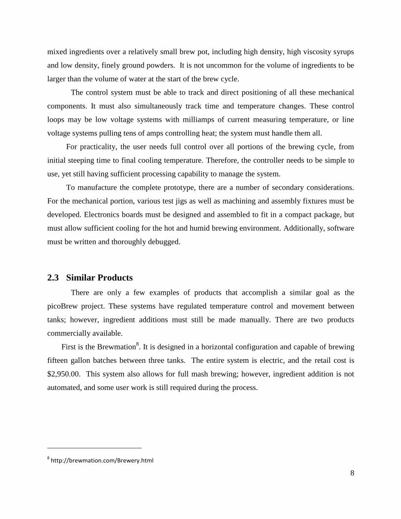
2.3 Similar Products
There are only a few examples of products that accomplish a similar goal as the
picoBrew project. These systems have regulated temperature control and movement between
tanks; however, ingredient additions must still be made manually. There are two products
commercially available.
First is the Brewmation8. It is designed in a horizontal configuration and capable of brewing
fifteen gallon batches between three tanks. The entire system is electric, and the retail cost is
$2,950.00. This system also allows for full mash brewing; however, ingredient addition is not
automated, and some user work is still required during the process.
8 http://brewmation.com/Brewery.html
9
Next is the Brew-Zer System9. Unlike the Brewmation, it is designed in a vertical fashion
and is capable of brewing five to eleven gallon batches. It is propane heated, with the rest of the
systems being electrical and has a retail price of $2399.99.
The picoBrew projects aims to fill the gap in the current market by developing a small
scale automated brewery in the five gallon range, at a price point under $750. There are currently
no commercial products in this category. Such a product is expected to draw interest from more
advanced hobby brewers looking for an affordable automated system.
9 http://www.homebrew.com/shopping/static/BREWZER.shtml
10
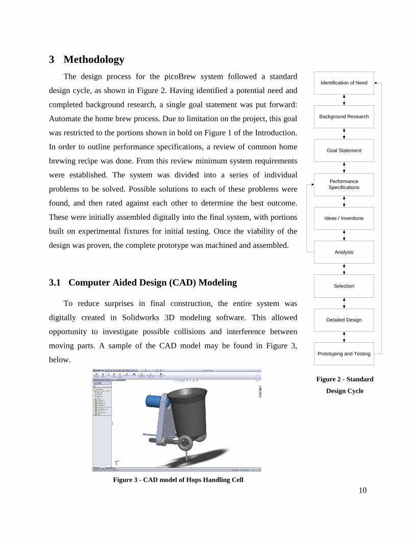
3 Methodology
The design process for the picoBrew system followed a standard
design cycle, as shown in Figure 2. Having identified a potential need and
completed background research, a single goal statement was put forward:
Automate the home brew process. Due to limitation on the project, this goal
was restricted to the portions shown in bold on Figure 1 of the Introduction.
In order to outline performance specifications, a review of common home
brewing recipe was done. From this review minimum system requirements
were established. The system was divided into a series of individual
problems to be solved. Possible solutions to each of these problems were
found, and then rated against each other to determine the best outcome.
These were initially assembled digitally into the final system, with portions
built on experimental fixtures for initial testing. Once the viability of the
design was proven, the complete prototype was machined and assembled.
3.1 Computer Aided Design (CAD) Modeling
To reduce surprises in final construction, the entire system was
digitally created in Solidworks 3D modeling software. This allowed
opportunity to investigate possible collisions and interference between
moving parts. A sample of the CAD model may be found in Figure 3,
below.
Figure 3 - CAD model of Hops Handling Cell
Identification of Need
Background Research
Goal Statement
Performance
Specifications
Ideas / Inventions
Analysis
Selection
Detailed Design
Prototyping and Testing
Figure 2 - Standard
Design Cycle
11
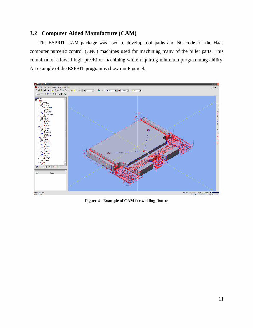
3.2 Computer Aided Manufacture (CAM)
The ESPRIT CAM package was used to develop tool paths and NC code for the Haas
computer numeric control (CNC) machines used for machining many of the billet parts. This
combination allowed high precision machining while requiring minimum programming ability.
An example of the ESPRIT program is shown in Figure 4.
Figure 4 - Example of CAM for welding fixture
12
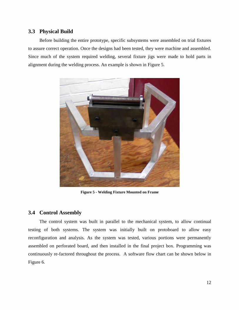
3.3 Physical Build
Before building the entire prototype, specific subsystems were assembled on trial fixtures
to assure correct operation. Once the designs had been tested, they were machine and assembled.
Since much of the system required welding, several fixture jigs were made to hold parts in
alignment during the welding process. An example is shown in Figure 5.
Figure 5 - Welding Fixture Mounted on Frame
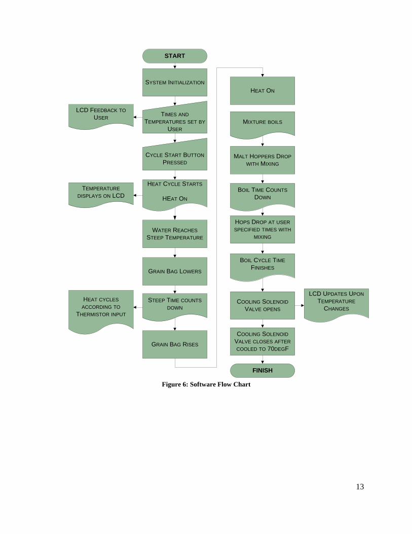
3.4 Control Assembly
The control system was built in parallel to the mechanical system, to allow continual
testing of both systems. The system was initially built on protoboard to allow easy
reconfiguration and analysis. As the system was tested, various portions were permanently
assembled on perforated board, and then installed in the final project box. Programming was
continuously re-factored throughout the process. A software flow chart can be shown below in
Figure 6.
13
SYSTEM INITIALIZATION
HOPS DROP AT USER
SPECIFIED TIMES WITH
MIXING
MALT HOPPERS DROP
WITH MIXING
COOLING SOLENOID
VALVE OPENS
COOLING SOLENOID
VALVE CLOSES AFTER
COOLED TO 70DEGF
GRAIN BAG LOWERS
GRAIN BAG RISES
HEAT CYCLE STARTS
HEAT ON
TIMES AND
TEMPERATURES SET BY
USER
CYCLE START BUTTON
PRESSED
STEEP TIME COUNTS
DOWN
MIXTURE BOILS
BOIL TIME COUNTS
DOWN
BOIL CYCLE TIME
FINISHES
FINISH
START
HEAT CYCLES
ACCORDING TO
THERMISTOR INPUT
TEMPERATURE
DISPLAYS ON LCD
LCD FEEDBACK TO
USER
LCD UPDATES UPON
TEMPERATURE
CHANGES
WATER REACHES
STEEP TEMPERATURE
HEAT ON
Figure 6: Software Flow Chart
14
4 Results
As outlined in the Methodology, the various options for each of the subsystems was analyze.
The final design was developed from the collated data then assembled and tested.
4.1 System Options There are a number of subsystems within the prototype, each with its own set of
challenges. To make design decisions, possible resolutions to each design challenge were
organized, with a listing of the advantages and drawbacks of each option.
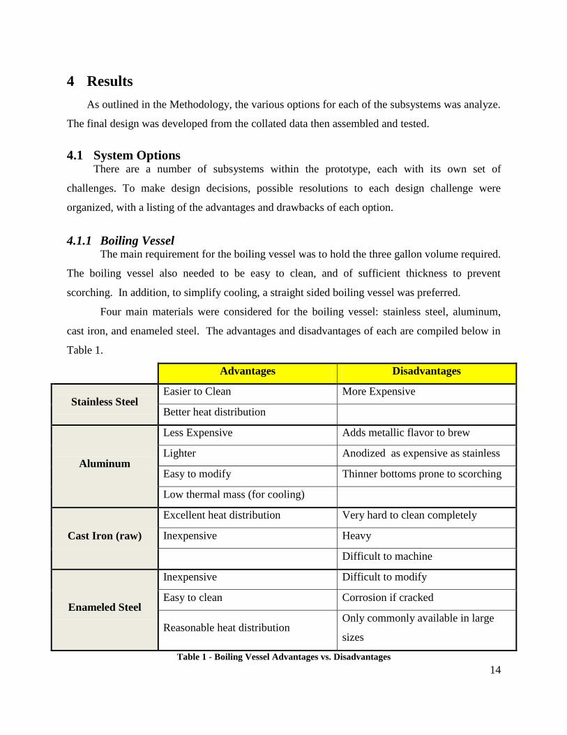
4.1.1 Boiling Vessel The main requirement for the boiling vessel was to hold the three gallon volume required.
The boiling vessel also needed to be easy to clean, and of sufficient thickness to prevent
scorching. In addition, to simplify cooling, a straight sided boiling vessel was preferred.
Four main materials were considered for the boiling vessel: stainless steel, aluminum,
cast iron, and enameled steel. The advantages and disadvantages of each are compiled below in
Table 1.
Advantages Disadvantages
Stainless Steel Easier to Clean More Expensive
Better heat distribution
Aluminum
Less Expensive Adds metallic flavor to brew
Lighter Anodized as expensive as stainless
Easy to modify Thinner bottoms prone to scorching
Low thermal mass (for cooling)
Cast Iron (raw)
Excellent heat distribution Very hard to clean completely
Inexpensive Heavy
Difficult to machine
Enameled Steel
Inexpensive Difficult to modify
Easy to clean Corrosion if cracked
Reasonable heat distribution Only commonly available in large
sizes
Table 1 - Boiling Vessel Advantages vs. Disadvantages
15
4.1.2 Heating Element
The main requirement for the heating element was to provide sufficient heat to boil the
required amount of water. The heating element also needed to be safe for indoor use, be easily
controlled, and use a readily available fuel or power source. The different options considered,
with their advantages and disadvantages, are listed below in Table 2.
Advantages Disadvantages
Natural Gas
No refill system required Harder to control
High heat output Safety issue with open flame
Not all houses equipped
Propane
High heat output Control issues
Easy availability Open flame safety concerns
Constant refills required
Electric Element
(resistive)
Simple High thermal mass
Inexpensive Difficult to clean
Can use relay for binary control High current requirements
Electric Element
(Inductive)
Easy control (relay) Expensive
Easy clean-up May not function with all pots
Higher efficiency (less heat lost to
room)
Cool to touch (safety advantage)
Submersion Heater
(electric)
Higher efficiency (all heat into brew) Hard to find appropriate size
No exposed heating element Difficult to clean
Expensive
Heat Exchange Coil
Can use same coil for cooling Complex pluming
Minimal chance of overheat/scorching Difficult to clean
Still requires external heat source
Table 2 – Heating Element Advantages vs. Disadvantages
16
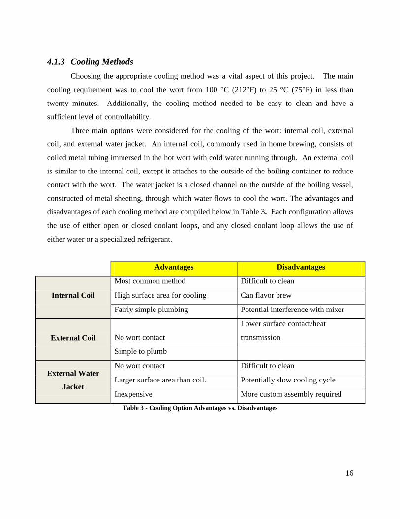
4.1.3 Cooling Methods
Choosing the appropriate cooling method was a vital aspect of this project. The main
cooling requirement was to cool the wort from 100 °C (212°F) to 25 °C (75°F) in less than
twenty minutes. Additionally, the cooling method needed to be easy to clean and have a
sufficient level of controllability.
Three main options were considered for the cooling of the wort: internal coil, external
coil, and external water jacket. An internal coil, commonly used in home brewing, consists of
coiled metal tubing immersed in the hot wort with cold water running through. An external coil
is similar to the internal coil, except it attaches to the outside of the boiling container to reduce
contact with the wort. The water jacket is a closed channel on the outside of the boiling vessel,
constructed of metal sheeting, through which water flows to cool the wort. The advantages and
disadvantages of each cooling method are compiled below in Table 3. Each configuration allows
the use of either open or closed coolant loops, and any closed coolant loop allows the use of
either water or a specialized refrigerant.
Advantages Disadvantages
Internal Coil
Most common method Difficult to clean
High surface area for cooling Can flavor brew
Fairly simple plumbing Potential interference with mixer
External Coil No wort contact
Lower surface contact/heat
transmission
Simple to plumb
External Water
Jacket
No wort contact Difficult to clean
Larger surface area than coil. Potentially slow cooling cycle
Inexpensive More custom assembly required
Table 3 - Cooling Option Advantages vs. Disadvantages
17
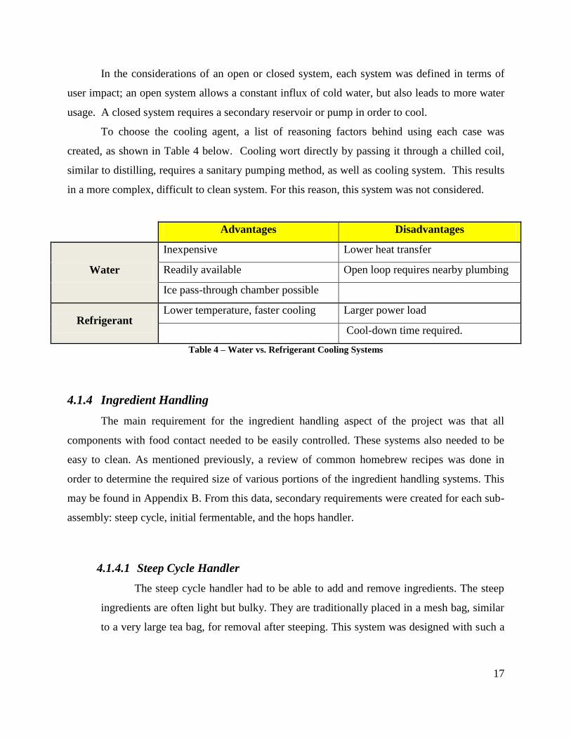
In the considerations of an open or closed system, each system was defined in terms of
user impact; an open system allows a constant influx of cold water, but also leads to more water
usage. A closed system requires a secondary reservoir or pump in order to cool.
To choose the cooling agent, a list of reasoning factors behind using each case was
created, as shown in Table 4 below. Cooling wort directly by passing it through a chilled coil,
similar to distilling, requires a sanitary pumping method, as well as cooling system. This results
in a more complex, difficult to clean system. For this reason, this system was not considered.
Advantages Disadvantages
Water
Inexpensive Lower heat transfer
Readily available Open loop requires nearby plumbing
Ice pass-through chamber possible
Refrigerant
Lower temperature, faster cooling Larger power load
Cool-down time required.
Table 4 – Water vs. Refrigerant Cooling Systems
4.1.4 Ingredient Handling
The main requirement for the ingredient handling aspect of the project was that all
components with food contact needed to be easily controlled. These systems also needed to be
easy to clean. As mentioned previously, a review of common homebrew recipes was done in
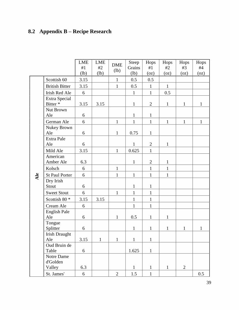
order to determine the required size of various portions of the ingredient handling systems. This
may be found in Appendix B. From this data, secondary requirements were created for each sub-
assembly: steep cycle, initial fermentable, and the hops handler.
4.1.4.1 Steep Cycle Handler
The steep cycle handler had to be able to add and remove ingredients. The steep
ingredients are often light but bulky. They are traditionally placed in a mesh bag, similar
to a very large tea bag, for removal after steeping. This system was designed with such a
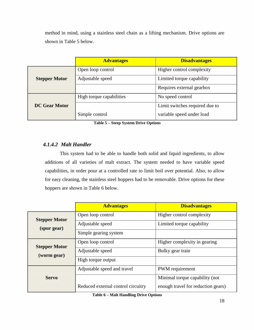
18
method in mind, using a stainless steel chain as a lifting mechanism. Drive options are
shown in Table 5 below.
Advantages Disadvantages
Stepper Motor
Open loop control Higher control complexity
Adjustable speed Limited torque capability
Requires external gearbox
DC Gear Motor
High torque capabilities No speed control
Simple control
Limit switches required due to
variable speed under load
Table 5 – Steep System Drive Options
4.1.4.2 Malt Handler
This system had to be able to handle both solid and liquid ingredients, to allow
additions of all varieties of malt extract. The system needed to have variable speed
capabilities, in order pour at a controlled rate to limit boil over potential. Also, to allow
for easy cleaning, the stainless steel hoppers had to be removable. Drive options for these
hoppers are shown in Table 6 below.
Advantages Disadvantages
Stepper Motor
(spur gear)
Open loop control Higher control complexity
Adjustable speed Limited torque capability
Simple gearing system
Stepper Motor
(worm gear)
Open loop control Higher complexity in gearing
Adjustable speed Bulky gear train
High torque output
Servo
Adjustable speed and travel PWM requirement
Reduced external control circuitry
Minimal torque capability (not
enough travel for reduction gears)
Table 6 – Malt Handling Drive Options
19
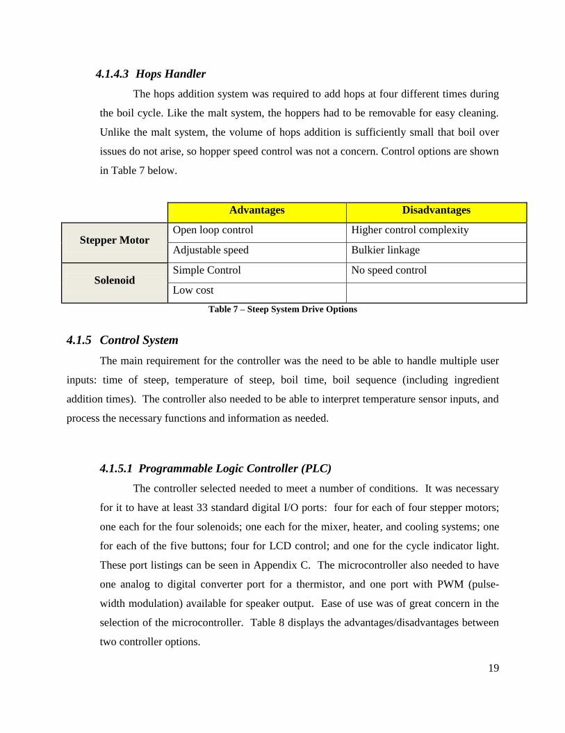
4.1.4.3 Hops Handler
The hops addition system was required to add hops at four different times during
the boil cycle. Like the malt system, the hoppers had to be removable for easy cleaning.
Unlike the malt system, the volume of hops addition is sufficiently small that boil over
issues do not arise, so hopper speed control was not a concern. Control options are shown
in Table 7 below.
Advantages Disadvantages
Stepper Motor Open loop control Higher control complexity
Adjustable speed Bulkier linkage
Solenoid Simple Control No speed control
Low cost
Table 7 – Steep System Drive Options
4.1.5 Control System
The main requirement for the controller was the need to be able to handle multiple user
inputs: time of steep, temperature of steep, boil time, boil sequence (including ingredient
addition times). The controller also needed to be able to interpret temperature sensor inputs, and
process the necessary functions and information as needed.
4.1.5.1 Programmable Logic Controller (PLC)
The controller selected needed to meet a number of conditions. It was necessary
for it to have at least 33 standard digital I/O ports: four for each of four stepper motors;
one each for the four solenoids; one each for the mixer, heater, and cooling systems; one
for each of the five buttons; four for LCD control; and one for the cycle indicator light.
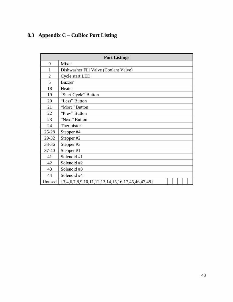
These port listings can be seen in Appendix C. The microcontroller also needed to have
one analog to digital converter port for a thermistor, and one port with PWM (pulse-
width modulation) available for speaker output. Ease of use was of great concern in the
selection of the microcontroller. Table 8 displays the advantages/disadvantages between
two controller options.
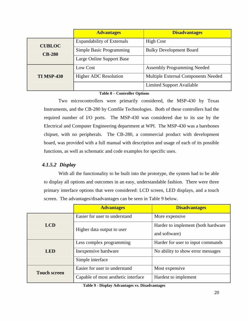
20
Advantages Disadvantages
CUBLOC
CB-280
Expandability of Externals High Cost
Simple Basic Programming Bulky Development Board
Large Online Support Base
TI MSP-430
Low Cost Assembly Programming Needed
Higher ADC Resolution Multiple External Components Needed
Limited Support Available
Table 8 – Controller Options
Two microcontrollers were primarily considered, the MSP-430 by Texas
Instruments, and the CB-280 by Comfile Technologies. Both of these controllers had the
required number of I/O ports. The MSP-430 was considered due to its use by the
Electrical and Computer Engineering department at WPI. The MSP-430 was a barebones
chipset, with no peripherals. The CB-280, a commercial product with development
board, was provided with a full manual with description and usage of each of its possible
functions, as well as schematic and code examples for specific uses.
4.1.5.2 Display
With all the functionality to be built into the prototype, the system had to be able
to display all options and outcomes in an easy, understandable fashion. There were three
primary interface options that were considered: LCD screen, LED displays, and a touch
screen. The advantages/disadvantages can be seen in Table 9 below.
Advantages Disadvantages
LCD
Easier for user to understand More expensive
Higher data output to user Harder to implement (both hardware
and software)
LED
Less complex programming Harder for user to input commands
Inexpensive hardware No ability to show error messages
Simple interface
Touch screen Easier for user to understand Most expensive
Capable of most aesthetic interface Hardest to implement
Table 9 - Display Advantages vs. Disadvantages
21
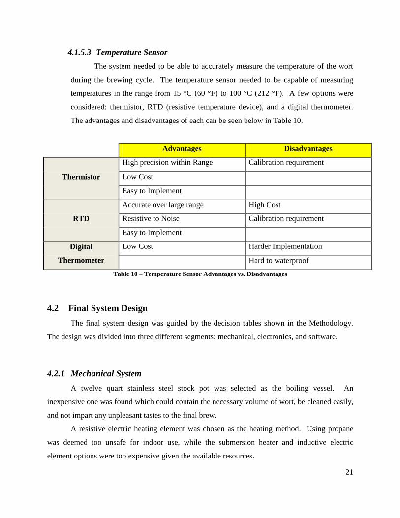
4.1.5.3 Temperature Sensor
The system needed to be able to accurately measure the temperature of the wort
during the brewing cycle. The temperature sensor needed to be capable of measuring
temperatures in the range from 15 °C (60 °F) to 100 °C (212 °F). A few options were
considered: thermistor, RTD (resistive temperature device), and a digital thermometer.
The advantages and disadvantages of each can be seen below in Table 10.
Advantages Disadvantages
Thermistor
High precision within Range Calibration requirement
Low Cost
Easy to Implement
RTD
Accurate over large range High Cost
Resistive to Noise Calibration requirement
Easy to Implement
Digital
Thermometer
Low Cost Harder Implementation
Hard to waterproof
Table 10 – Temperature Sensor Advantages vs. Disadvantages
4.2 Final System Design
The final system design was guided by the decision tables shown in the Methodology.
The design was divided into three different segments: mechanical, electronics, and software.
4.2.1 Mechanical System
A twelve quart stainless steel stock pot was selected as the boiling vessel. An
inexpensive one was found which could contain the necessary volume of wort, be cleaned easily,
and not impart any unpleasant tastes to the final brew.
A resistive electric heating element was chosen as the heating method. Using propane
was deemed too unsafe for indoor use, while the submersion heater and inductive electric
element options were too expensive given the available resources.
22
The water jacket was determined to be the option best suited to the projects cooling
needs. The cooling method chosen was an open loop, water cooled jacket with flow fully
circling the pot. Water cooling was chosen for simplicity and to reduce potential exposure to
possibly hazardous refrigerants. A solenoid valve, commonly used on dishwashers to control
input flow, was chosen to control the cold water flow. The cooling jacket was chosen over the
internal coil to reduce cleaning and contamination concerns.
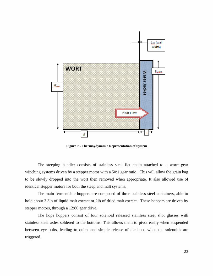
4.2.1.1 Cooling Thermodynamic Study
To prove feasibility as part of the decision process, a thermodynamic study was
completed on the external water jacket. In order to simplify such an analysis, several
assumptions were made. The water jacket system was calculated as a series of steady-
state systems with constant temperature differences between the wort and the cooling
water. The inner wall of the boiling vessel would be treated as a vertical plate heat
exchanger, with natural convection on the wort side and forced convection on the coolant
side. Research had shown that incoming ground water temperature would be an average
of about 13 °C (55 °F) in New England10
(up to 20 °C (68°F) in the extreme southern
United States) and therefore 13 °C was used. Water flow was presumed to be available at
1.5 gallons per minute, about 70% of the EPA mandated maximum of 2.2 gallons per
minute11
. An arbitrary size was chosen for the water jacket, one within the expected
range of size options, and a standard twelve quart, 304 stainless steel stock pot was used
for evaluation. A schematic diagram of the system is shown below in Figure 7.
Based on these assumptions, heat transfer rates were calculated at temperature
extremes, as well as at an average value. From the total heat removal required and the
heat transfer rate, a time value for each temperature case was then calculated. These
values fell within the acceptable range of cooling times. These calculations can be found
in Appendix A.
10 http://public.dep.state.ma.us/wsc_viewer/Default.aspx?formdataid=0&documentid=9113
11 http://www.epa.gov/WaterSense/pubs/bathroom_faucets.htm
23
Figure 7 - Thermoydynamic Representation of System
The steeping handler consists of stainless steel flat chain attached to a worm-gear
winching systems driven by a stepper motor with a 50:1 gear ratio. This will allow the grain bag
to be slowly dropped into the wort then removed when appropriate. It also allowed use of
identical stepper motors for both the steep and malt systems.
The main fermentable hoppers are composed of three stainless steel containers, able to
hold about 3.3lb of liquid malt extract or 2lb of dried malt extract. These hoppers are driven by
stepper motors, through a 12:80 gear drive.
The hops hoppers consist of four solenoid released stainless steel shot glasses with
stainless steel axles soldered to the bottoms. This allows them to pivot easily when suspended
between eye bolts, leading to quick and simple release of the hops when the solenoids are
triggered.
24
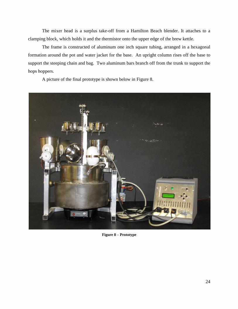
The mixer head is a surplus take-off from a Hamilton Beach blender. It attaches to a
clamping block, which holds it and the thermistor onto the upper edge of the brew kettle.
The frame is constructed of aluminum one inch square tubing, arranged in a hexagonal
formation around the pot and water jacket for the base. An upright column rises off the base to
support the steeping chain and bag. Two aluminum bars branch off from the trunk to support the
hops hoppers.
A picture of the final prototype is shown below in Figure 8.
Figure 8 – Prototype
25
4.2.2 Control System
4.2.2.1 Control Hardware
For materials handling, stepper motors were chosen for both steep and hops
handlers, with solenoids being used to control the hops hoppers. The Minebea-Matsushita
Motor Corporation PM55L stepper motor was chosen for its high torque capabilities and
reasonable price. The Ledex, Inc. 191172-001 was chosen as the best solenoid for the
intended purpose, due to its easy availability and low cost.
The power supply needed to be able to provide power to all DC components that
could possibly be running at one time. The maximum load situation involved the CB-280
running at full capacity, a fan running, and one stepper motor running. The stepper motor
required about 800 mA at 24V running at full capacity. The CB-280 comes standard with
a 12V 500 mA power supply, so this was assumed to be its maximum load. The case fan
required about 200 mA at 12V. A 24V power supply was necessary in order to be able to
run the stepper motors, and could be stepped down to 12V using a voltage regulator to
run the CB-280 board, fan, and solenoids. Assuming 80% efficiency in the conversion
from 24V to 12V, the fan and CB-280 board would need 420 mA total at 24V to make
the required 700 mA at 12V. The power supply had to be able to provide at least 1220
mA at 24V with conversion from a 120VAC line. The Power-One # MAP42-1024 was
selected. This power supply provides 1700 milliamps at 24VDC from an input source of
85-264 VAC. The additional power capacity provides for unexpected inefficiencies or
overlooked loads, as well as future expansion.
A thermistor was eventually chosen for temperature sensing. These devices were
readily available in the temperature range required, with high precision and accuracy.
Although calibration was needed, it ensured that the reading at the controller would
match the temperature across the appropriate range.
The RTD was too expensive and lacked the required precision needed over the
wide temperature range. The digital thermometer, being an integrated circuit (IC), would
have been difficult to waterproof as well as implement with our current control system.
26
In order to interface the CB-280 with the various powered components, a series of
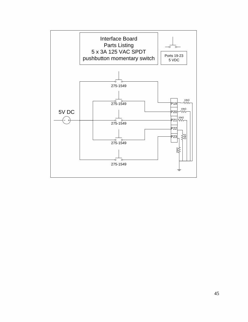
control boards was created. Schematics for these can be found in Appendix D.
Solid-state relays were needed in order to control 120V power to the heater,
mixer, and the cooling valve with the CB-280. For the heater, which runs at 1100 watts,
a relay of at least 10 amps was needed, and the D-240A10Z was used. Both the mixer
and the cooling valve required less than 1 Amp of power and the Crouzet M-OAC5-315
was used to control these two components.
Both the stepper motors and the solenoids required a voltage and current larger
than what could be supplied by the CB-280 so MOSFET-based control boards were built
to control these components. The control board for each stepper motor required four
MOSFETS, eight Schottky diodes, and four 10kOhm resistors. The MOSFETS, when
activated, provided the grounding for each of the four signal lines on the stepper motor
which were connected to the source pins on the MOSFET. The source pins were wired
with Schottky diodes to provide protection against potential power surges. The CB-280
was connected to the gate lines on the MOSFET, so that when a 5V signal was sent from
the microcontroller, the MOSFET would allow electron flow. The gate also contained a
10kOhm pull down resistor which allowed for faster voltage drop and therefore quicker
switching of the MOSFET. The drain on the MOSFET was wired directly to ground.
The solenoid control board required fewer components. Each solenoid only
required a single MOSFET and 10kOhm resistor. The I/O pin from the CB-280 was
wired to the MOSFET gate, and a 10kOhm resistor was wired from the gate to ground,
once again to provide for faster switching. One side of the solenoid was wired to the
source on the MOSFET, and the drain was wired to ground.
From the available display options, the LCD screen was chosen. Comfile
Technologies, our chosen controller manufacturer, had available prewritten code and
attachment points for an LCD which allowed for easy output to the LCD screen.
While the touchscreen would have simplified input and output, the cost was
beyond the scope of this project. The LED display would have been more difficult to
understand, less adaptable, and more challenging in the long run. A single LED was used
as a signal indicator light, but not to display any values.
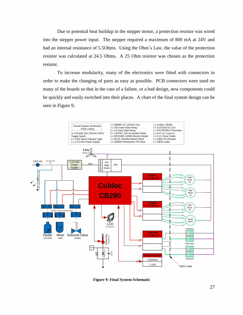
27
Due to potential heat buildup in the stepper motor, a protection resistor was wired
into the stepper power input. The stepper required a maximum of 800 mA at 24V and
had an internal resistance of 5.5Ohms. Using the Ohm’s Law, the value of the protection
resistor was calculated at 24.5 Ohms. A 25 Ohm resistor was chosen as the protection
resistor.
To increase modularity, many of the electronics were fitted with connectors in
order to make the changing of parts as easy as possible. PCB connectors were used on
many of the boards so that in the case of a failure, or a bad design, new components could
be quickly and easily switched into their places. A chart of the final system design can be
seen in Figure 9.
FAND80BH-12
1
2
3
4
1
2
3
4
120V AC
Solenoids
275-636 DPST1.7A 24V
Power
Supply
10A Relay
Cubloc
CB280
LCDCLCD216-G
Dis
t B
oa
rd
24V
Malt
Motor
#3
4
3
2
1
Steep
Motor
Stepper
3 + 4 Board
Solenoids
1 - 4 Board
Solenoid
Solenoid
Malt
Motor
#1
4
3
2
1
Malt
Motor
#2
Stepper
1 + 2 Board
4
4
4
2
2
4
6
NT
CA
PIP
E3
Th
erm
isto
r
1A Relay 1A Relay
Solenoid Valve303650
120VAC 15A Grounded Outlets
12
0V
Ne
on
Ind
ica
tor L
igh
t10A
SS Relay
MixerHB51
HeaterCE23309
1A
SS Relay
1A
SS Relay
Interface Board
5 Buttons
1 LED
5.1
V Z
en
er
0.4
7u
F
10
kΩ
P24
DB25 Cable
1 x DB0BH-12 120VDC Fan
1 x 10A Solid State Relay
2 x 1A Solid State Relay
3 x 120VAC 15A Grounded Outlet
1 x DE23309 1100W Electric Heater
1 x No.51 Hamilton Beach Mixer
1 x 303650 Dishwasher Fill Valve
Overall System Schematic
Parts Listing
1 x Cubloc CB280
1 x CLCD216-G LCD
1 x NTCAPIPE3 Thermistor
1 x 0.47 µF Capacitor
1 x 5.1V Zener Diode
1 x 10kΩ 1% Resistor
1 x DB25 Cable
1x 275-636 20A 125VAC DPST
Toggle Switch
1 x 120V Neon Indicator Light
1 x 1.7A 24V Power Supply
24V12V
Step
Down
Figure 9: Final System Schematic
28
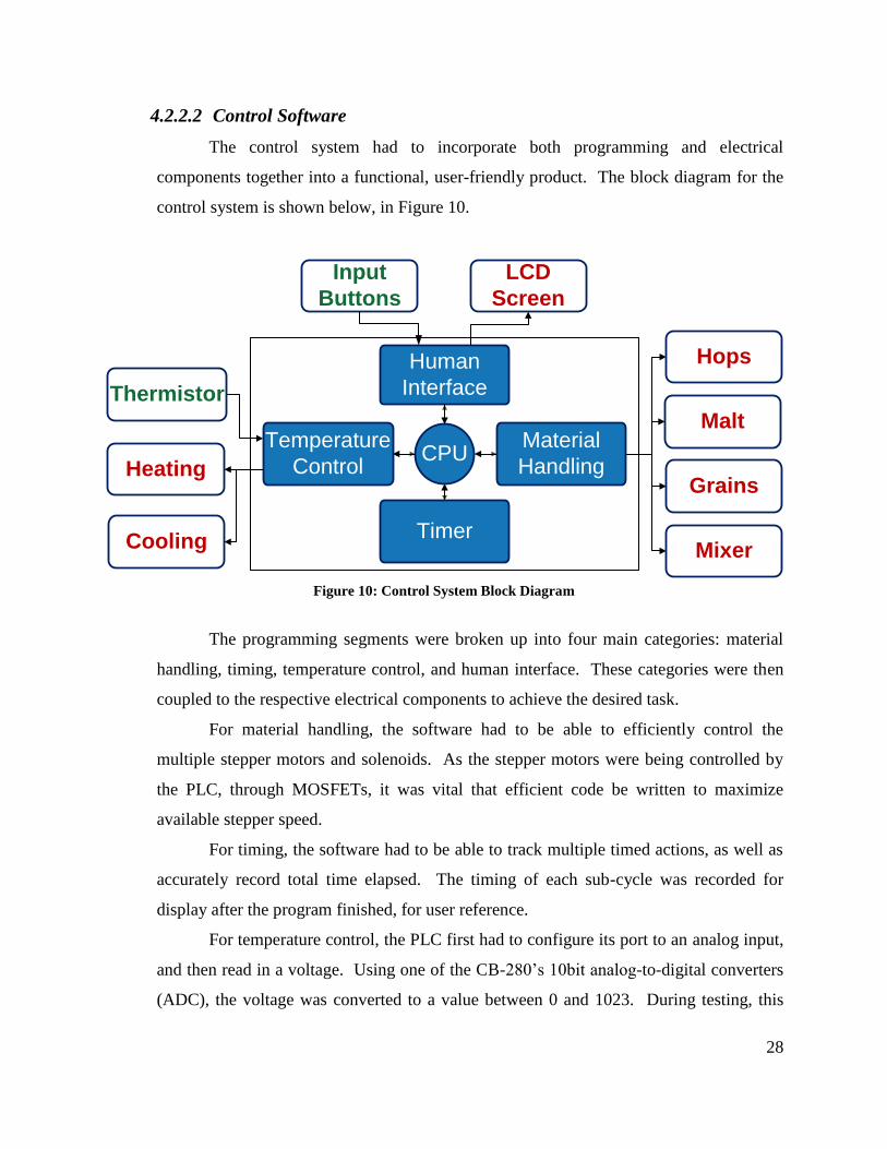
4.2.2.2 Control Software
The control system had to incorporate both programming and electrical
components together into a functional, user-friendly product. The block diagram for the
control system is shown below, in Figure 10.
Malt
Hops
Grains
Mixer
LCD
Screen
Input
Buttons
Thermistor
Heating
Cooling
Temperature
Control
Material
Handling
Human
Interface
Timer
CPU
Figure 10: Control System Block Diagram
The programming segments were broken up into four main categories: material
handling, timing, temperature control, and human interface. These categories were then
coupled to the respective electrical components to achieve the desired task.
For material handling, the software had to be able to efficiently control the
multiple stepper motors and solenoids. As the stepper motors were being controlled by
the PLC, through MOSFETs, it was vital that efficient code be written to maximize
available stepper speed.
For timing, the software had to be able to track multiple timed actions, as well as
accurately record total time elapsed. The timing of each sub-cycle was recorded for
display after the program finished, for user reference.
For temperature control, the PLC first had to configure its port to an analog input,
and then read in a voltage. Using one of the CB-280’s 10bit analog-to-digital converters
(ADC), the voltage was converted to a value between 0 and 1023. During testing, this
29
data was recorded and compared with temperature data, allowing accurate calibration of
the complete system. Due to accuracy requirements in the cooling, steeping, and boiling
ranges, three independent calibration curves were implemented to achieve highest
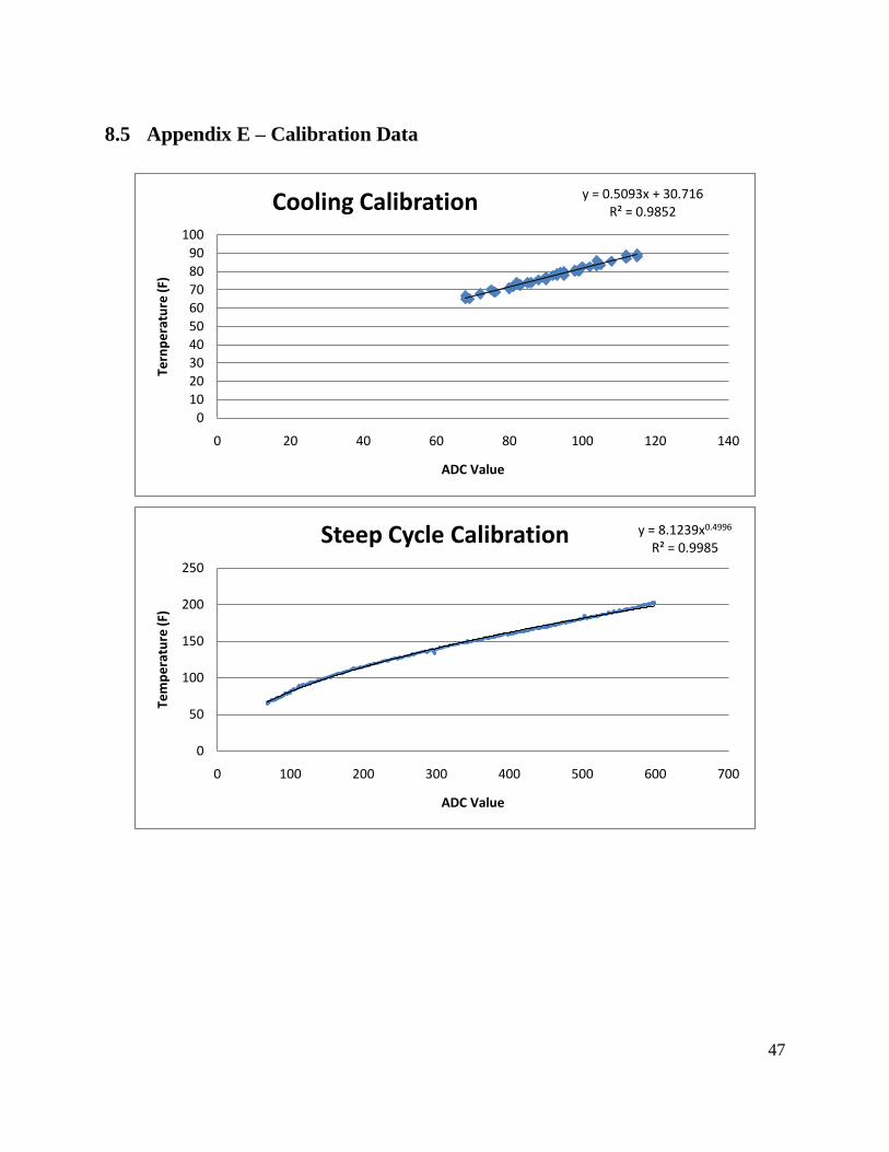
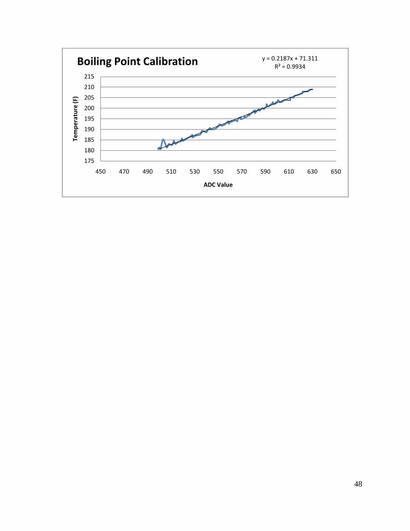
precision in the required ranges. Calibration data can be seen in Appendix E.
On the human interface side, the code had to both retrieve and output the required
information in the most user-friendly way possible, while limiting possibilities for input
errors. The general menu flow was designed to cater to both novice and advanced
brewers. Novice users can choose a preset recipe, load ingredients, and press “Cycle
Start.” Advanced users can choose a custom cycle, with the ability to control all timing
and temperature decisions. The user also has the option of saving up to three custom
recipes and cycles for future use. An annotated flow chart of the menu options may be
found in Appendix F.
4.3 System Performance
The picoBrew prototype proved quite capable during both dry runs and final testing. The
system was able to read and control temperature to within 1.1 °C (2 °F) throughout the entire
cycle, with the ability to read within 0.28 °C (0.5 °F) within the important portions of the steep,
heat, and cool stages. Timing control was consistent within one second over the course of the
average three hour brewing cycle. Cooling was rapid despite minor plumbing leaks.
However, final testing showed a few easily correctable flaws in the prototype. The
heating element chosen was barely sufficient to boil the wort, and suffered from a drop in
temperature during ingredient additions. The current prototype is unable to support a larger
heating element due to the current limit on the solid state relay controlling the heater. However,
replacing this relay with a similar but higher-rated unit would allow the use of a larger heating
system.
The second issue which arose was with the mixer head. As the wort boils away, the fluid
level may drop, reducing the amount of fluid covering the mixing head. This can result in the
propulsion of hot sticky wort above the edges of the brew kettle, coating any object within a one
meter radius. This can be corrected by extending the mixer shaft several inches, insuring that the
mixer head is submerged at all times.

30
The final issue was with the steep system. When tested with the largest steep requirements,
the winch proved unable to lift the waterlogged grain bag from the brew kettle. A more powerful
stepper motor would overcome this problem easily.
31
5 Conclusion and Recommendations
The picoBrew prototype works well as a proof of concept. It handles the heating and
cooling stages of the brewing cycle with excellent temperature and timing control. Reception
amongst home brewers and other interested individuals was uniformly positive, with many
expressing an interest in commercialization.
It is hoped that this project will be continued at WPI, as there are many upgrades and
additions that could be made. For example, a system intended to control and track the
fermentation cycle would be a clear continuation. Temperature control is vital to consistent
fermentation, and the ability to record alcohol level as measured by hydrometer would allow
brewers greater control over the timing of secondary fermentation and bottling.
A full mash cycle could also be added to the system. This addition would require a
second stainless steel vessel capable of holding about three gallons of water, a second heating
element, a second thermistor, a pump, a plastic five gallon mash tank, and water level sensor.
This full grain system would not require the current steep or primary fermentable handlers. This
system could be easily added onto the current setup and would allow the system to be sold with
various setups for different level brewers.
Even within the scope of the current prototype, there are many areas where systems could
be updated. The control system could be streamlined by a team with greater experience in
electronics. A superior cooling jacket could be fabricated, possibly of an annular aluminum
design to be pressed onto the stainless brewing pot. This would reduce leakage and allow direct
contact between the brew kettle and heating element.
32
6 Business Plan
Assessment of Market Viability
The beer market within the country is expanding both in production and value, with an
increase of 1.7% in production volume in the overall market and an increase of 12% in sales for
craft brews alone. The beer market has since been increasing each year, and the expansion in the
market shows that markets within are sustainable.
According to the most recent data presented in the The Annual Beer Handbook on
consumer characteristics there appears to be a reasonable market for the picoBrew. Currently
there are 202.9 million people12
within the legal beer drinking community of the United States.
However, the population of homebrewers within the beer drinking population is
unknown. Because of this, data pertaining to the craft brew community was analyzed to account
for the specialty of homebrewing within the general market. Craft brews consist of the section of
the market pertaining to brewpubs, microbreweries and regional craft brewers. The United
States largest homebrewing organization, the American Homebrewers Association (AHA) has
released approximations of its membership size. The AHA currently has around 17,000 active
members13
, which represents only a portion of the homebrew population because only registered,
due paying members are counted.
Of the 202.9 million people in the beer drinking population 9.6 percent fall into the
market of craft beer drinkers. This amounts to approximately 19.5 million people. In this subset
of the community 70.8% make over $60,000 a year in pretax income, amounting to 13.8 million
people14
.
While a viable market appears to exist in the homebrewing community, interactions
between competitors in a market can create challenges for small companies depending on cost
structure and demand within the market. This may be lead to a minimum share of the market
being required to remain competitive15
.
12 2007. Consumer characteristics. The Beer Handbook. p172(10)
13 http://www.beertown.org/homebrewing/membership.html
14 2007. Consumer characteristics. The Beer Handbook. p172(10)
15 Karnani, Aneel. Minimum Market Share. Marketing Science, Vol. 2, No. 1 (Winter, 1983), pp. 75-93
33
However, specialization within a market lessens the minimum market share required. In
a case where a company is able to carve a niche in the market the minimum market share
decreases.
In the case of the picoBrew project there would be no minimum market share because of
a lack of competition and the specialization of the market. With no comparable products in the
market in either scale or cost, the picoBrew project would be able to hold a competitive niche in
the market allowing sales to be independent of larger competition in the market.
Using the membership of the AHA as a population base and an estimated market share of
between 1% and 5% the customer base for the picoBrew project can be estimated between 1,700
and 8,500 people.
Consumer Needs
The consumer needs for the product determined the systems added to the product in
development. To this end, a survey was taken to gain a basic understanding of the desires of
homebrewers in an automated system.
The set of survey questions in Appendix G were distributed over two internet forum sites
targeted towards the homebrew community. Ratebeer.com and Beeradvocate.com are both
websites that focus on craft brewing a commercial and home scale. These sites are frequented by
practitioners of the hobby and enthusiasts who are more focused on the works of the commercial
brewers.
Overall, the design of the picoBrew project matched the desired system capabilities of
respondents to the survey, with the system having at least the minimal capabilities users would
look for in a home brew system. The results of the survey questions can be seen in Appendix G.
Manufacturing Cost Considerations
Three major costs are associated with the manufacturing process: materials, direct labor,
and overhead costs. In the analysis of the manufacturing cost of the picoBrew prototype, only
cost of materials and manufacturing labor are evaluated.
Material cost for the prototype of the system can be seen within the bill of materials
(BOM). The BOM was developed with the principles of the manufacturing process in mind,
34
reducing the number of levels in the BOM to a minimum. Garwood16
states that “an over
structured bill of materials generally implies long lead times, unnecessary tasks, and, thus, higher
costs.”
The levels within the BOM presented in appendix H were chosen to divide the various
processes in manufacturing to allow for each level of a subsystem to only require one type of
labor. This was done to assist in the process of the cost analysis, so that each section of the
BOM has an associated material, and labor cost.
The costs of materials in the BOM are representative of the prototyping costs of the
project. Material costs can be reduced in the transition from prototyping to production due to
bulk discounts from suppliers on materials. The cost of ideal materials should average around
50% of the total manufacturing cost17
.
Direct labor costs in the production of a product average between 12% and 15% of the
total manufacturing cost. The cost of direct labor is a product of the man hours and the wage
rates specific to the type of labor being performed.
While this cost estimate follows a simple base function, the factors of variability in labor
productivity can alter the estimate associated with manufacturing labor. A base productivity can
be defined in order to account for the regional variables associated with manufacturing18
.
The manufacturing of the picoBrew prototype would require several types of employees
based upon their specialized skills; specifically machinists, welders and assemblers.
Machinist’s wages depend largely on the training and experience they have completed,
and on the level of detail in the job, with precision jobs paying higher wages. In the United
States the mean hourly wage of a general machinist is $17.36 where as the mean hourly wage
increases to $19.72 when only Massachusetts is considered.19
Welders are defined by the Bureau of Labor Statistics as a group of workers whose
specialty centers on welding, soldering and brazing operations. Welder’s job in a manufacturing
process varies between skill levels and the level of automation in a process.
16 Garwood, Dave. 1995. Bill of Materials. Dogwood Publishing Company, Inc. Marietta, GA
17 Black, J.T. 1991. The Design of the Factory with a Future. McGraw Hill Inc. New York. P. 14.
18 Clark, F.D., and Lorenzoni, A.B. 1985, Applied Cost Engineering. Marcel Dekker, INC. New York. Chpt 5
19 http://www.bls.gov/oco/ocos223.htm
35
The mean hourly wage of a welder in the US is $15.43 for general or all purchase
machinery welding operations. However, in Massachusetts this is increased to $19.68 since
Massachusetts is ranked one of the highest paying states in this profession.
Assemblers fall into one of two categories needed for an automated project. The physical
body of the product must be assembled in line with the electronic components being assembled.
In the end these two subassemblies are brought together to create the finished product. Since
assembly is a less specialize vocation in comparison to welding and machining it can be
expected that the mean hourly wages are less, with electronics assemblers making $13.7520
and
team assemblers making $12.7221
System Prototype Cost
This data was used along with the production time estimates made based upon our build
of the prototype system to determine what the prototyping cost of the picoBrew project was. The
detailed breakdown of material cost can be seen in the BOM in appendix H while the wage cost
can be seen in appendix I.
Overall the prototyping of the picobrew project cost $994.12 in material cost. This
includes the cost of materials that were freely available to us in Washburn shops stock.
Labor cost or the product was determined using the mean hourly wage of the various types of
work needed to carry out the production of the prototype. Labor cost came to a total of $339.69
including an estimated 18.8 labor hours. In addition to this, a productivity factor of 90% was
used to offset the relation of worker conditions to efficiency of employees. The total cost of the
picoBrew prototype and labor came out to be $1,333.81.
Future of Commercialization
Future considerations for the commercialization of the picoBrew project include reducing
production cost and including a focus on the design for manufacturability. Cost can be reduced
by both streamlining the existing processes and making the system as a whole more efficient.
While the picoBrew prototype acts as a valid proof of concept for the idea of a small scale,
20 http://www.bls.gov/oes/current/oes512022.htm#ind
21 http://www.bls.gov/oes/current/oes512092.htm

36
affordable, automated homebrewing system it would have to be redesigned to be both more
mechanically effective, and aesthetically appealing to the consumer before it could be taken into
the market.
37
8 Appendices
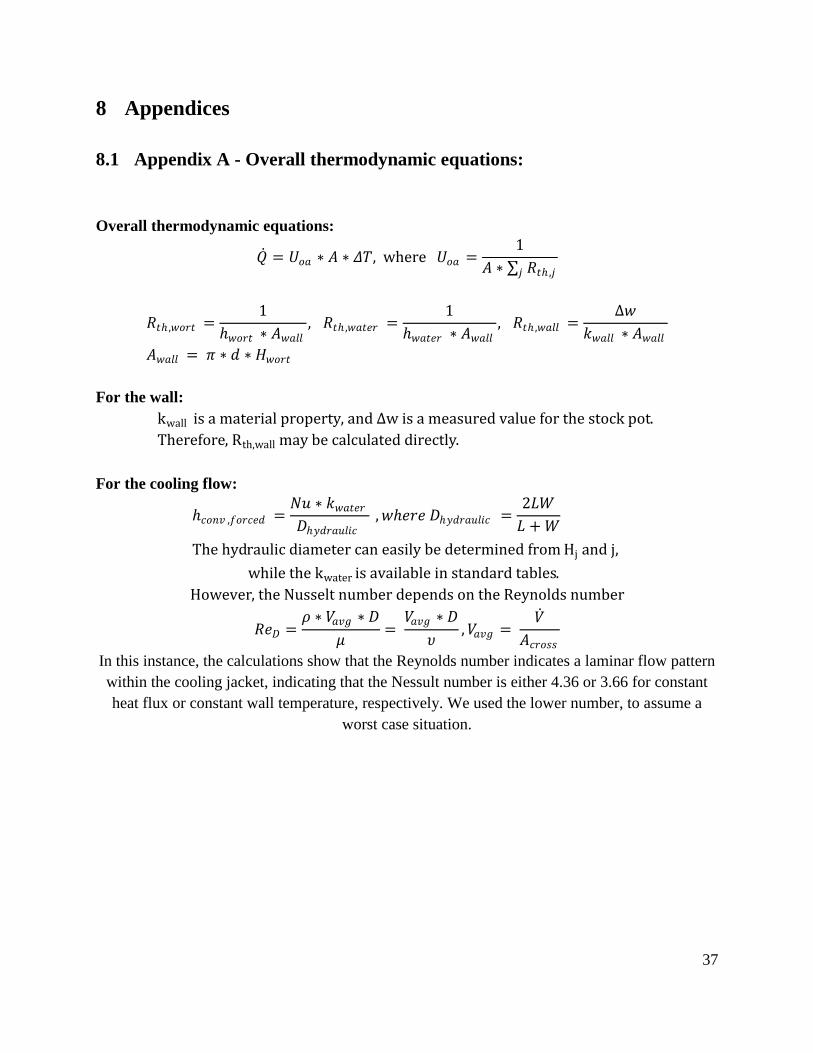
8.1 Appendix A - Overall thermodynamic equations:
Overall thermodynamic equations:
𝑄 = 𝑈𝑜𝑎 ∗ 𝐴 ∗ 𝛥𝑇, where 𝑈𝑜𝑎 =1
𝐴 ∗ 𝑅𝑡 ,𝑗𝑗
𝑅𝑡 ,𝑤𝑜𝑟𝑡 =1
𝑤𝑜𝑟𝑡 ∗ 𝐴𝑤𝑎𝑙𝑙, 𝑅𝑡 ,𝑤𝑎𝑡𝑒𝑟 =
1
𝑤𝑎𝑡𝑒𝑟 ∗ 𝐴𝑤𝑎𝑙𝑙, 𝑅𝑡 ,𝑤𝑎𝑙𝑙 =
∆𝑤
𝑘𝑤𝑎𝑙𝑙 ∗ 𝐴𝑤𝑎𝑙𝑙
𝐴𝑤𝑎𝑙𝑙 = 𝜋 ∗ 𝑑 ∗ 𝐻𝑤𝑜𝑟𝑡
For the wall:
kwall is a material property, and ∆w is a measured value for the stock pot.
Therefore, Rth,wall may be calculated directly.
For the cooling flow:
𝑐𝑜𝑛𝑣 ,𝑓𝑜𝑟𝑐𝑒𝑑 =𝑁𝑢 ∗ 𝑘𝑤𝑎𝑡𝑒𝑟𝐷𝑦𝑑𝑟𝑎𝑢𝑙𝑖𝑐
,𝑤𝑒𝑟𝑒 𝐷𝑦𝑑𝑟𝑎𝑢𝑙𝑖𝑐 =2𝐿𝑊
𝐿 + 𝑊
The hydraulic diameter can easily be determined from Hj and j,
while the kwater is available in standard tables.
However, the Nusselt number depends on the Reynolds number
𝑅𝑒𝐷 =𝜌 ∗ 𝑉𝑎𝑣𝑔 ∗ 𝐷
𝜇=
𝑉𝑎𝑣𝑔 ∗ 𝐷
𝜐,𝑉𝑎𝑣𝑔 =
𝑉
𝐴𝑐𝑟𝑜𝑠𝑠
In this instance, the calculations show that the Reynolds number indicates a laminar flow pattern
within the cooling jacket, indicating that the Nessult number is either 4.36 or 3.66 for constant
heat flux or constant wall temperature, respectively. We used the lower number, to assume a
worst case situation.
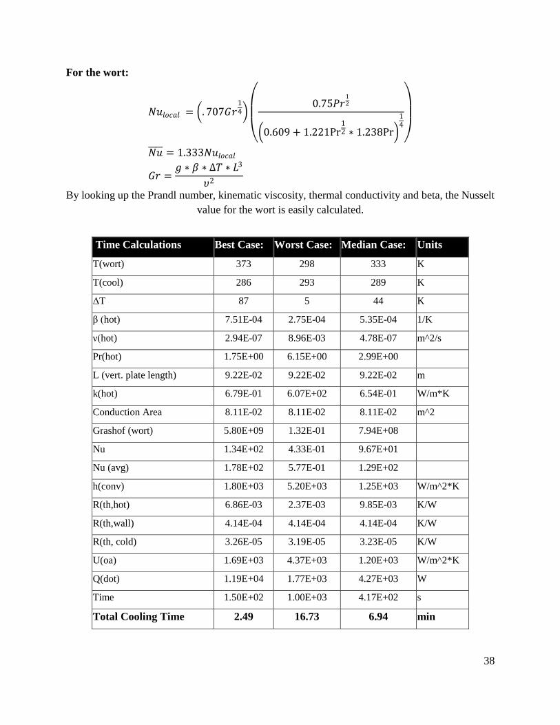
38
For the wort:
𝑁𝑢𝑙𝑜𝑐𝑎𝑙 = . 707𝐺𝑟14
0.75𝑃𝑟
12
0.609 + 1.221Pr12 ∗ 1.238Pr
14
𝑁𝑢 = 1.333𝑁𝑢𝑙𝑜𝑐𝑎𝑙
𝐺𝑟 =𝑔 ∗ 𝛽 ∗ ∆𝑇 ∗ 𝐿3
𝜐2
By looking up the Prandl number, kinematic viscosity, thermal conductivity and beta, the Nusselt
value for the wort is easily calculated.
Time Calculations Best Case: Worst Case: Median Case: Units
T(wort) 373 298 333 K
T(cool) 286 293 289 K
ΔT 87 5 44 K
β (hot) 7.51E-04 2.75E-04 5.35E-04 1/K
ν(hot) 2.94E-07 8.96E-03 4.78E-07 m^2/s
Pr(hot) 1.75E+00 6.15E+00 2.99E+00
L (vert. plate length) 9.22E-02 9.22E-02 9.22E-02 m
k(hot) 6.79E-01 6.07E+02 6.54E-01 W/m*K
Conduction Area 8.11E-02 8.11E-02 8.11E-02 m^2
Grashof (wort) 5.80E+09 1.32E-01 7.94E+08
Nu 1.34E+02 4.33E-01 9.67E+01
Nu (avg) 1.78E+02 5.77E-01 1.29E+02
h(conv) 1.80E+03 5.20E+03 1.25E+03 W/m^2*K
R(th,hot) 6.86E-03 2.37E-03 9.85E-03 K/W
R(th,wall) 4.14E-04 4.14E-04 4.14E-04 K/W
R(th, cold) 3.26E-05 3.19E-05 3.23E-05 K/W
U(oa) 1.69E+03 4.37E+03 1.20E+03 W/m^2*K
Q(dot) 1.19E+04 1.77E+03 4.27E+03 W
Time 1.50E+02 1.00E+03 4.17E+02 s
Total Cooling Time 2.49 16.73 6.94 min
39
8.2 Appendix B – Recipe Research
LME
#1
(lb)
LME
#2
(lb)
DME
(lb)
Steep
Grains
(lb)
Hops
#1
(oz)
Hops
#2
(oz)
Hops
#3
(oz)
Hops
#4
(oz)
Ale
Scottish 60 3.15 1 0.5 0.5
British Bitter 3.15 1 0.5 1 1
Irish Red Ale 6 1 1 0.5
Extra Special
Bitter * 3.15 3.15 1 2 1 1 1
Nut Brown
Ale 6 1 1
German Ale 6 1 1 1 1 1 1
Nukey Brown
Ale 6 1 0.75 1
Extra Pale
Ale 6 1 2 1
Mild Ale 3.15 1 0.625 1
American
Amber Ale 6.3 1 2 1
Kolsch 6 1 1 1
St Paul Porter 6 1 1 1 1
Dry Irish
Stout 6 1 1
Sweet Stout 6 1 1 1
Scottish 80 * 3.15 3.15 1 1
Cream Ale 6 1 1
English Pale
Ale 6 1 0.5 1 1
Tongue
Splitter 6 1 1 1 1 1
Irish Draught
Ale 3.15 1 1 1 1
Oud Bruin de
Table 6 1.625 1
Notre Dame
d'Golden
Valley 6.3 1 1 1 2
St. James' 6 2 1.5 1 0.5
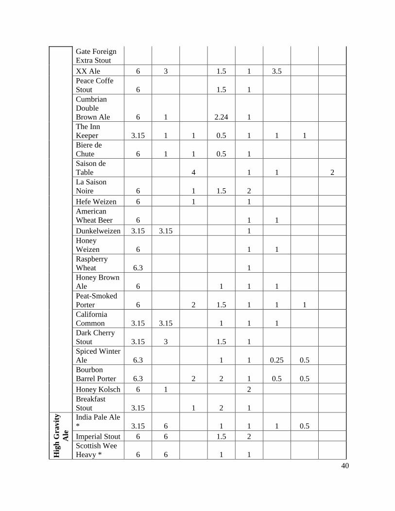
40
Gate Foreign
Extra Stout
XX Ale 6 3 1.5 1 3.5
Peace Coffe
Stout 6 1.5 1
Cumbrian
Double
Brown Ale 6 1 2.24 1
The Inn
Keeper 3.15 1 1 0.5 1 1 1
Biere de
Chute 6 1 1 0.5 1
Saison de
Table 4 1 1 2
La Saison
Noire 6 1 1.5 2
Hefe Weizen 6 1 1
American
Wheat Beer 6 1 1
Dunkelweizen 3.15 3.15 1
Honey
Weizen 6 1 1
Raspberry
Wheat 6.3 1
Honey Brown
Ale 6 1 1 1
Peat-Smoked
Porter 6 2 1.5 1 1 1
California
Common 3.15 3.15 1 1 1
Dark Cherry
Stout 3.15 3 1.5 1
Spiced Winter
Ale 6.3 1 1 0.25 0.5
Bourbon
Barrel Porter 6.3 2 2 1 0.5 0.5
Honey Kolsch 6 1 2
Breakfast
Stout 3.15 1 2 1
Hig
h G
ravit
y
Ale
India Pale Ale
* 3.15 6 1 1 1 0.5
Imperial Stout 6 6 1.5 2
Scottish Wee
Heavy * 6 6 1 1
41
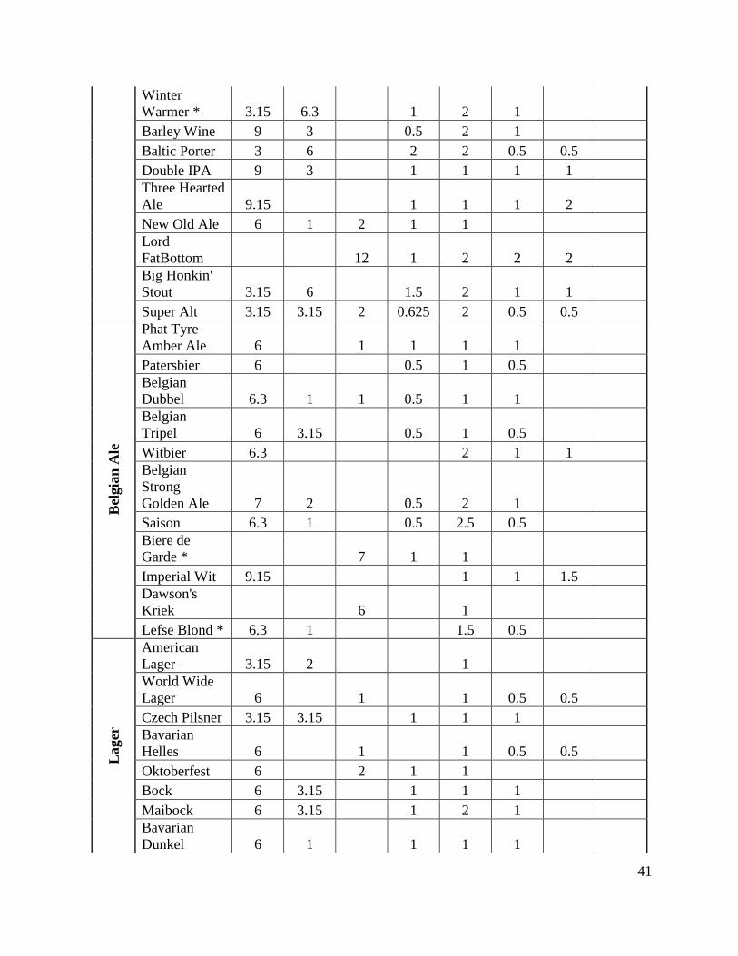
Winter
Warmer * 3.15 6.3 1 2 1
Barley Wine 9 3 0.5 2 1
Baltic Porter 3 6 2 2 0.5 0.5
Double IPA 9 3 1 1 1 1
Three Hearted
Ale 9.15 1 1 1 2
New Old Ale 6 1 2 1 1
Lord
FatBottom 12 1 2 2 2
Big Honkin'
Stout 3.15 6 1.5 2 1 1
Super Alt 3.15 3.15 2 0.625 2 0.5 0.5
Bel
gia
n A
le
Phat Tyre
Amber Ale 6 1 1 1 1
Patersbier 6 0.5 1 0.5
Belgian
Dubbel 6.3 1 1 0.5 1 1
Belgian
Tripel 6 3.15 0.5 1 0.5
Witbier 6.3 2 1 1
Belgian
Strong
Golden Ale 7 2 0.5 2 1
Saison 6.3 1 0.5 2.5 0.5
Biere de
Garde * 7 1 1
Imperial Wit 9.15 1 1 1.5
Dawson's
Kriek 6 1
Lefse Blond * 6.3 1 1.5 0.5
Lager
American
Lager 3.15 2 1
World Wide
Lager 6 1 1 0.5 0.5
Czech Pilsner 3.15 3.15 1 1 1
Bavarian
Helles 6 1 1 0.5 0.5
Oktoberfest 6 2 1 1
Bock 6 3.15 1 1 1
Maibock 6 3.15 1 2 1
Bavarian
Dunkel 6 1 1 1 1
42
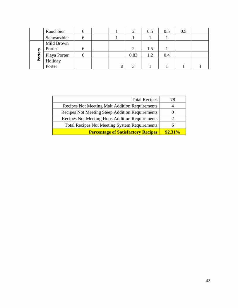
Rauchbier 6 1 2 0.5 0.5 0.5
Schwarzbier 6 1 1 1 1 P
ort
ers
Mild Brown
Porter 6 2 1.5 1
Playa Porter 6 0.83 1.2 0.4
Holiday
Porter 3 3 1 1 1 1
Total Recipes 78
Recipes Not Meeting Malt Addition Requirements 4
Recipes Not Meeting Steep Addition Requirements 0
Recipes Not Meeting Hops Addition Requirements 2
Total Recipes Not Meeting System Requirements 6
Percentage of Satisfactory Recipes 92.31%
43
8.3 Appendix C – CuBloc Port Listing
Port Listings
0 Mixer
1 Dishwasher Fill Valve (Coolant Valve)
2 Cycle start LED
5 Buzzer
18 Heater
19 “Start Cycle” Button
20 “Less” Button
21 “More” Button
22 “Prev” Button
23 “Next” Button
24 Thermistor
25-28 Stepper #4
29-32 Stepper #2
33-36 Stepper #3
37-40 Stepper #1
41 Solenoid #1
42 Solenoid #2
43 Solenoid #3
44 Solenoid #4
Unused {3,4,6,7,8,9,10,11,12,13,14,15,16,17,45,46,47,48}

44
8.4 Appendix D – Schematic Diagrams
24V
Vin1
Vout2
GND
0
0.3
3µ
F 0.1
µF
FAND80BH-12
Solenoids
Cubloc
CB280
4
Vin1
Vout2
GND
0
0.3
3µ
F 0.1
µF
Distribution Board
Parts Listing
2 x L7812CV Voltage Regulator
2 x 0.33µF Capacitor
2 x 0.1µF Capacitor
45
P19
P20
P21
P22
P23
5V DC
275-1549
275-1549
275-1549
275-1549
275-1549
Interface Board
Parts Listing
5 x 3A 125 VAC SPDT
pushbutton momentary switchPorts 19-23
5 VDC
10kΩ
10kΩ
10kΩ
10kΩ
10kΩ
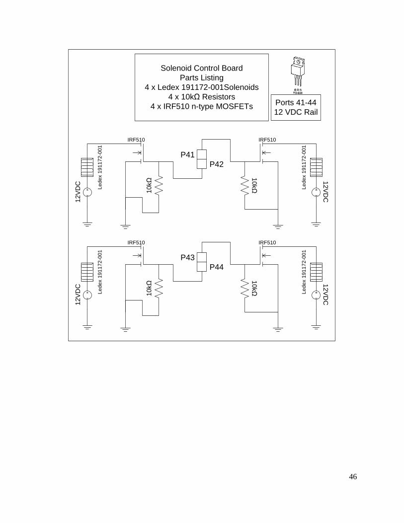
46
12
VD
C
IRF510
10kΩ
Le
de
x 1
91
17
2-0
01
12V
DC
IRF510
10kΩ
Le
de
x 1
91
17
2-0
01
P41
P42
12
VD
C
IRF510
10
kΩ
Le
de
x 1
91
17
2-0
01
12
VD
C
IRF510
10
kΩ
Le
de
x 1
91
17
2-0
01
P43
P44
Solenoid Control Board
Parts Listing
4 x Ledex 191172-001Solenoids
4 x 10kΩ Resistors
4 x IRF510 n-type MOSFETsPorts 41-44
12 VDC Rail
47
8.5 Appendix E – Calibration Data
y = 0.5093x + 30.716R² = 0.9852
0
10
20
30
40
50
60
70
80
90
100
0 20 40 60 80 100 120 140
Tern
pe
ratu
re (
F)
ADC Value
Cooling Calibration
y = 8.1239x0.4996
R² = 0.9985
0
50
100
150
200
250
0 100 200 300 400 500 600 700
Tem
pe
ratu
re (
F)
ADC Value
Steep Cycle Calibration
48
y = 0.2187x + 71.311R² = 0.9934
175
180
185
190
195
200
205
210
215
450 470 490 510 530 550 570 590 610 630 650
Tem
pe
ratu
re (
F)
ADC Value
Boiling Point Calibration
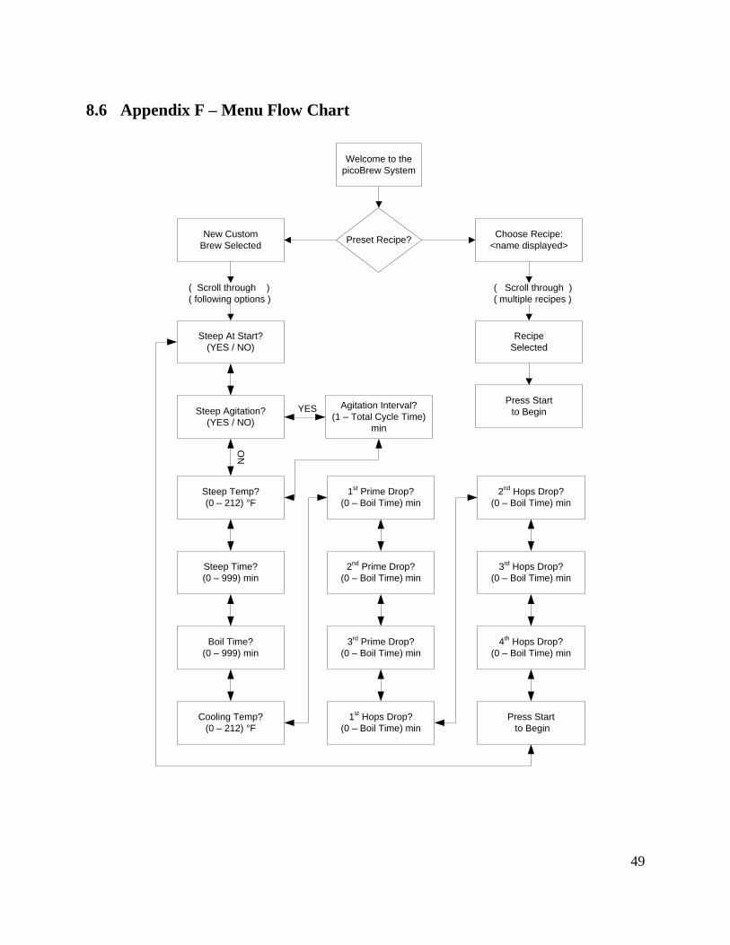
49
8.6 Appendix F – Menu Flow Chart
NO
Welcome to the
picoBrew System
Preset Recipe?New Custom
Brew Selected
Choose Recipe:
<name displayed>
Recipe
Selected
Press Start
to Begin
( Scroll through )
( multiple recipes )
( Scroll through )
( following options )
Steep At Start?
(YES / NO)
Steep Agitation?
(YES / NO)
Steep Temp?
(0 – 212) °F
Steep Time?
(0 – 999) min
Boil Time?
(0 – 999) min
Cooling Temp?
(0 – 212) °F
1st Prime Drop?
(0 – Boil Time) min
2nd
Prime Drop?
(0 – Boil Time) min
3rd
Prime Drop?
(0 – Boil Time) min
2nd
Hops Drop?
(0 – Boil Time) min
1st Hops Drop?
(0 – Boil Time) min
3rd
Hops Drop?
(0 – Boil Time) min
4th Hops Drop?
(0 – Boil Time) min
Press Start
to Begin
Agitation Interval?
(1 – Total Cycle Time)
min
YES
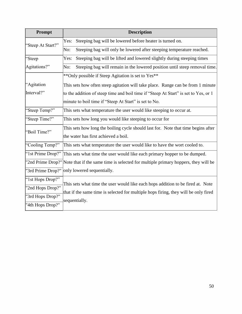
50
Prompt Description
“Steep At Start?” Yes: Steeping bag will be lowered before heater is turned on.
No: Steeping bag will only be lowered after steeping temperature reached.
“Steep
Agitations?”
Yes: Steeping bag will be lifted and lowered slightly during steeping times
No: Steeping bag will remain in the lowered position until steep removal time.
“Agitation
Interval?”
**Only possible if Steep Agitation is set to Yes**
This sets how often steep agitation will take place. Range can be from 1 minute
to the addition of steep time and boil time if “Steep At Start” is set to Yes, or 1
minute to boil time if “Steep At Start” is set to No.
“Steep Temp?” This sets what temperature the user would like steeping to occur at.
“Steep Time?” This sets how long you would like steeping to occur for
“Boil Time?” This sets how long the boiling cycle should last for. Note that time begins after
the water has first achieved a boil.
“Cooling Temp?” This sets what temperature the user would like to have the wort cooled to.
“1st Prime Drop?” This sets what time the user would like each primary hopper to be dumped.
Note that if the same time is selected for multiple primary hoppers, they will be
only lowered sequentially.
"2nd Prime Drop?"
"3rd Prime Drop?"
“1st Hops Drop?” This sets what time the user would like each hops addition to be fired at. Note
that if the same time is selected for multiple hops firing, they will be only fired
sequentially.
"2nd Hops Drop?"
"3rd Hops Drop?"
"4th Hops Drop?"
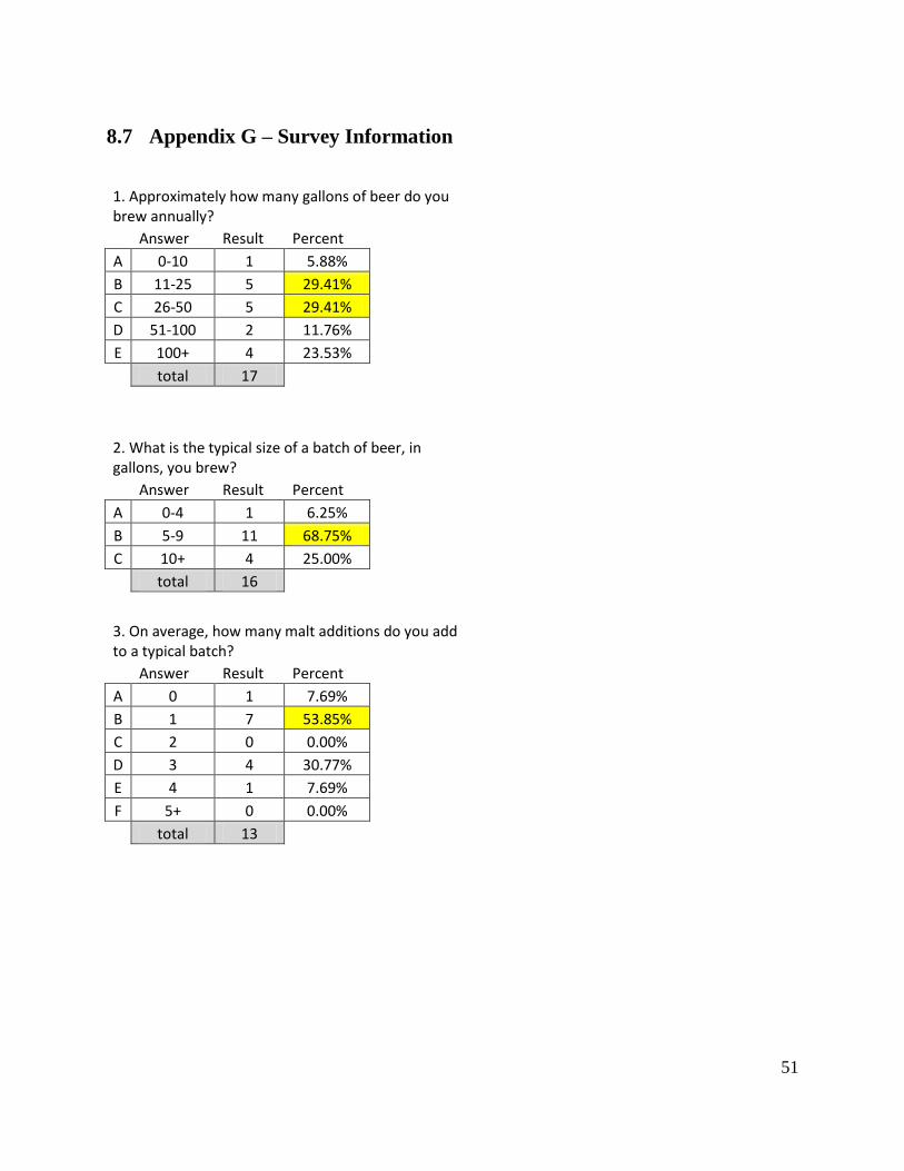
51
8.7 Appendix G – Survey Information
1. Approximately how many gallons of beer do you brew annually?
Answer Result Percent
A 0-10 1 5.88% B 11-25 5 29.41% C 26-50 5 29.41% D 51-100 2 11.76% E 100+ 4 23.53%
total 17
2. What is the typical size of a batch of beer, in gallons, you brew?
Answer Result Percent
A 0-4 1 6.25% B 5-9 11 68.75% C 10+ 4 25.00%
total 16
3. On average, how many malt additions do you add to a typical batch?
Answer Result Percent
A 0 1 7.69% B 1 7 53.85% C 2 0 0.00% D 3 4 30.77% E 4 1 7.69% F 5+ 0 0.00%
total 13
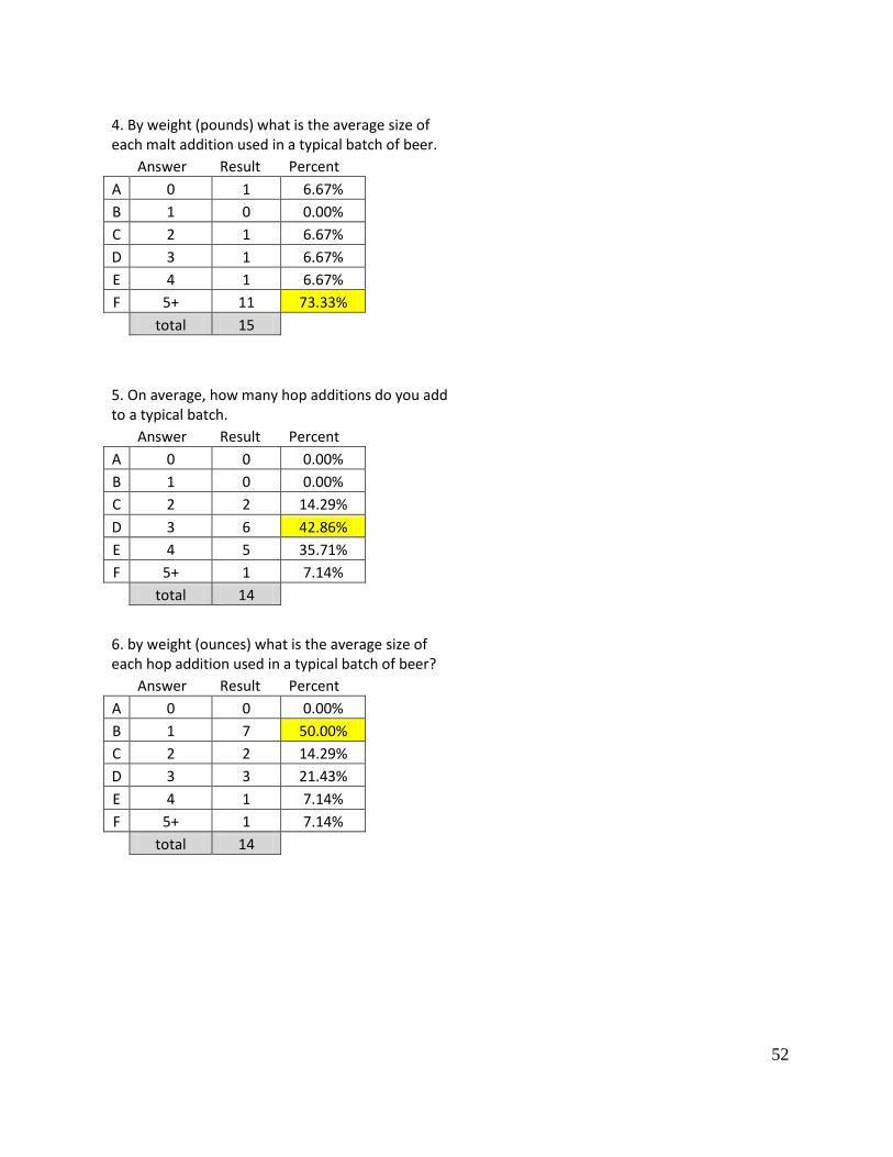
52
4. By weight (pounds) what is the average size of each malt addition used in a typical batch of beer.
Answer Result Percent
A 0 1 6.67% B 1 0 0.00% C 2 1 6.67% D 3 1 6.67% E 4 1 6.67% F 5+ 11 73.33%
total 15
5. On average, how many hop additions do you add to a typical batch.
Answer Result Percent
A 0 0 0.00% B 1 0 0.00% C 2 2 14.29% D 3 6 42.86% E 4 5 35.71% F 5+ 1 7.14%
total 14
6. by weight (ounces) what is the average size of each hop addition used in a typical batch of beer?
Answer Result Percent
A 0 0 0.00% B 1 7 50.00% C 2 2 14.29% D 3 3 21.43% E 4 1 7.14% F 5+ 1 7.14%
total 14
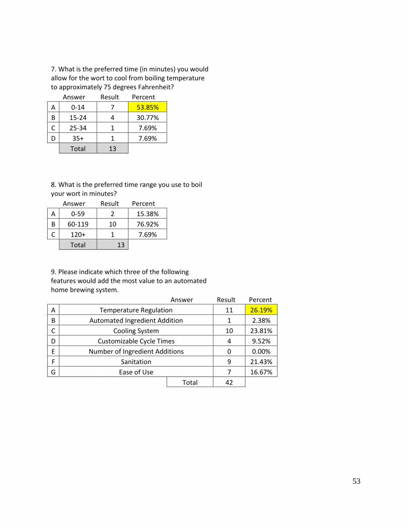
53
7. What is the preferred time (in minutes) you would allow for the wort to cool from boiling temperature to approximately 75 degrees Fahrenheit?
Answer Result Percent
A 0-14 7 53.85% B 15-24 4 30.77% C 25-34 1 7.69% D 35+ 1 7.69%
Total 13
8. What is the preferred time range you use to boil your wort in minutes?
Answer Result Percent
A 0-59 2 15.38% B 60-119 10 76.92% C 120+ 1 7.69%
Total 13
9. Please indicate which three of the following features would add the most value to an automated home brewing system.
Answer Result Percent
A Temperature Regulation 11 26.19%
B Automated Ingredient Addition 1 2.38%
C Cooling System 10 23.81%
D Customizable Cycle Times 4 9.52%
E Number of Ingredient Additions 0 0.00%
F Sanitation 9 21.43%
G Ease of Use 7 16.67%
Total 42
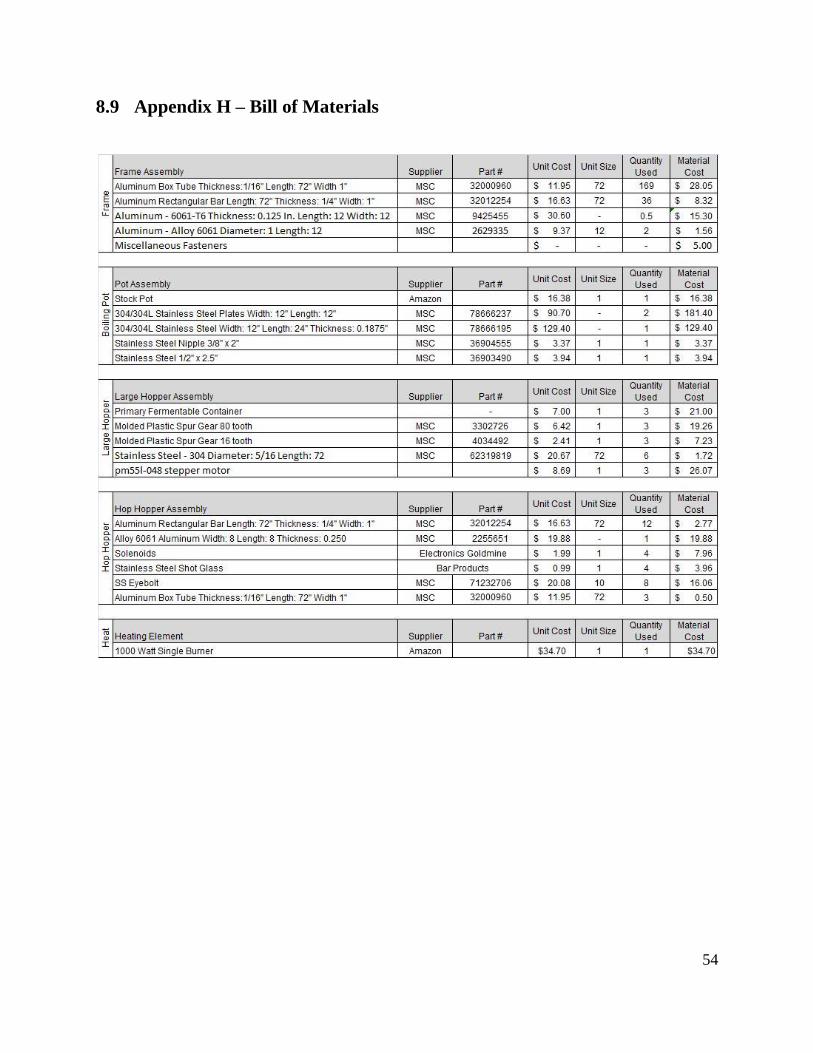
54
8.9 Appendix H – Bill of Materials
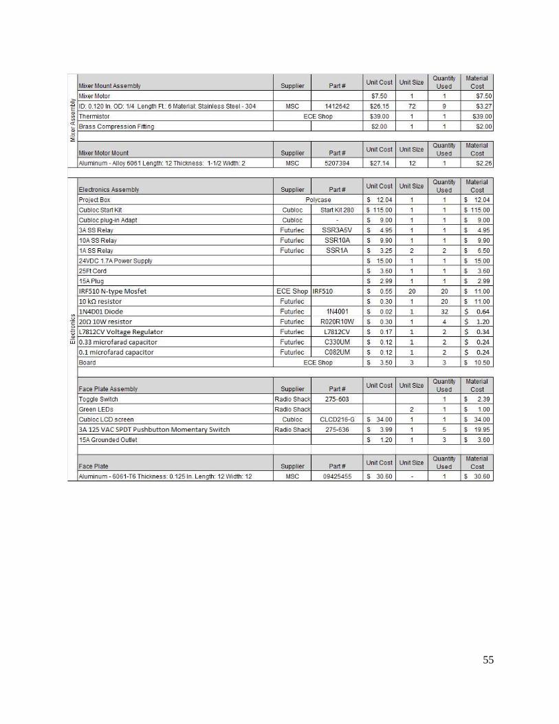
55
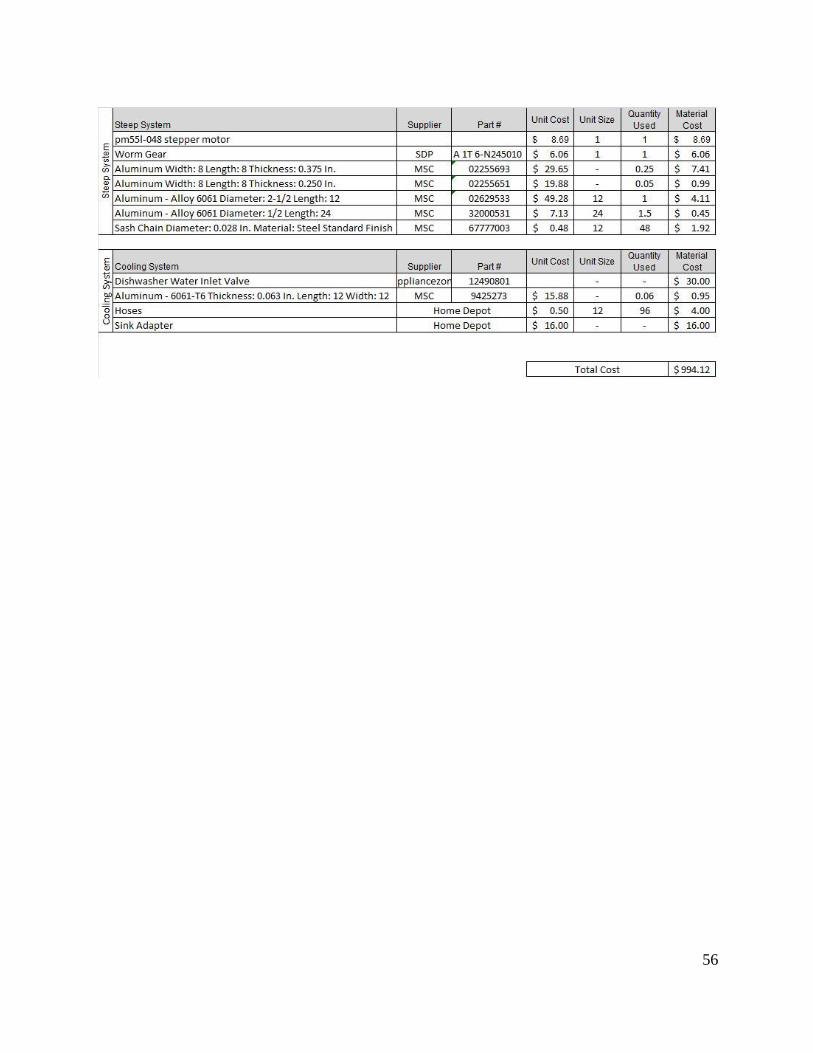
56
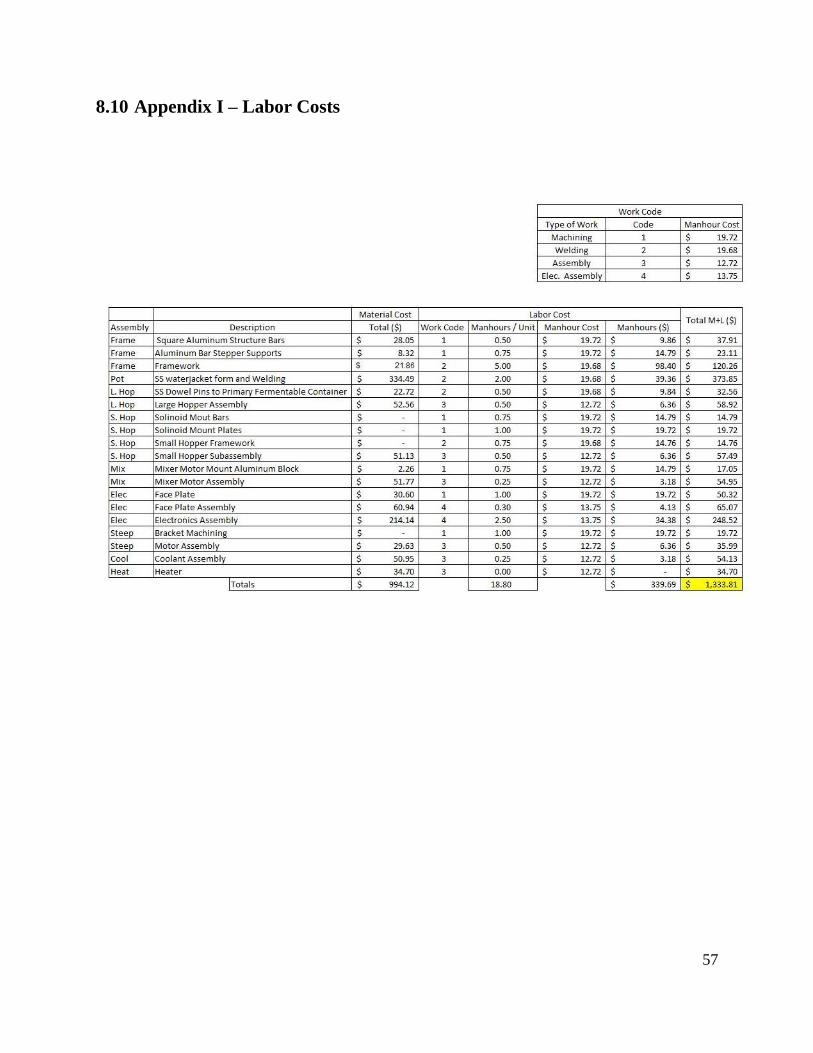
57
8.10 Appendix I – Labor Costs
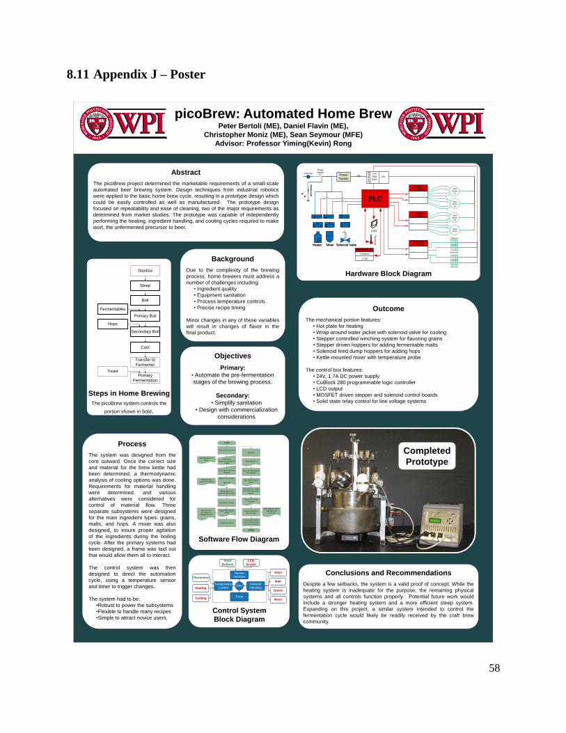
58
8.11 Appendix J – Poster
picoBrew: Automated Home BrewPeter Bertoli (ME), Daniel Flavin (ME),
Christopher Moniz (ME), Sean Seymour (MFE)
Advisor: Professor Yiming(Kevin) Rong
Abstract
The picoBrew project determined the marketable requirements of a small-scale
automated beer brewing system. Design techniques from industrial robotics
were applied to the basic home brew cycle, resulting in a prototype design which
could be easily controlled as well as manufactured. The prototype design
focused on repeatability and ease of cleaning, two of the major requirements as
determined from market studies. The prototype was capable of independently
performing the heating, ingredient handling, and cooling cycles required to make
wort, the unfermented precursor to beer.
Objectives
Primary: • Automate the pre-fermentation
stages of the brewing process.
Secondary: • Simplify sanitation
• Design with commercialization
considerations
Background
Due to the complexity of the brewing
process, home brewers must address a
number of challenges including:
• Ingredient quality
• Equipment sanitation
• Process temperature controls
• Precise recipe timing
Minor changes in any of these variables
will result in changes of flavor in the
final product.
Steps in Home Brewing
The picoBrew system controls the
portion shown in bold.
Sterilize
Steep
Boil
Fermentables
Primary Boil
Hops
Secondary Boil
Cool
Transfer to
Fermenter
YeastPrimary
Fermentation
Outcome
The mechanical portion features:
• Hot plate for heating
• Wrap-around water jacket with solenoid valve for cooling
• Stepper controlled winching system for flavoring grains
• Stepper driven hoppers for adding fermentable malts
• Solenoid fired dump hoppers for adding hops
• Kettle-mounted mixer with temperature probe
The control box features:
• 24V, 1.7A DC power supply
• CuBlock 280 programmable logic controller
• LCD output
• MOSFET driven stepper and solenoid control boards
• Solid state relay control for line voltage systems
Conclusions and Recommendations
Despite a few setbacks, the system is a valid proof of concept. While the
heating system is inadequate for the purpose, the remaining physical
systems and all controls function properly. Potential future work would
include a stronger heating system and a more efficient steep system.
Expanding on this project, a similar system intended to control the
fermentation cycle would likely be readily received by the craft brew
community.
Hardware Block Diagram
Completed
Prototype
1
2
3
4
1
2
3
4
120V AC
Solenoids
Power
Switch
Ind
ica
tor L
igh
t
Power
Supply
10A Relay
MixerHeater
PLC
LCD
Dis
t B
oard 12V
Step
Down
24V
Malt
Motor
#3
4
3
2
1
Steep
Motor
Stepper
3 + 4 Board
Solenoids
1 - 4 Board
Solenoid
Solenoid
Malt
Motor
#1
4
3
2
1
Malt
Motor
#2
Stepper
1 + 2 Board
4
4
4
2
2
4
6
Therm
isto
r
1A Relay 1A Relay
Solenoid Valve
Ind
ica
tor L
igh
t
10A Relay
MixerHeater
1A Relay 1A Relay
Solenoid Valve
Interface Board
5 Buttons
1 LED
24V
Process
The system was designed from the
core outward. Once the correct size
and material for the brew kettle had
been determined, a thermodynamic
analysis of cooling options was done.
Requirements for material handling
were determined, and various
alternatives were considered for
control of material flow. Three
separate subsystems were designed
for the main ingredient types: grains,
malts, and hops. A mixer was also
designed, to insure proper agitation
of the ingredients during the boiling
cycle. After the primary systems had
been designed, a frame was laid out
that would allow them all to interact.
The control system was then
designed to direct the automation
cycle, using a temperature sensor
and timer to trigger changes.
The system had to be:
•Robust to power the subsystems
•Flexible to handle many recipes
•Simple to attract novice users.
SYSTEM INITIALIZATION
HOPS DROP AT USER
SPECIFIED TIMES WITH
MIXING
MALT HOPPERS DROP
WITH MIXING
COOLING SOLENOID
VALVE OPENS
COOLING SOLENOID
VALVE CLOSES AFTER
COOLED TO 70DEGF
GRAIN BAG LOWERS
GRAIN BAG RISES
HEAT CYCLE STARTS
HEAT ON
TIMES AND
TEMPERATURES SET BY
USER
CYCLE START BUTTON
PRESSED
STEEP TIME COUNTS
DOWN
MIXTURE BOILS
BOIL TIME COUNTS
DOWN
BOIL CYCLE TIME
FINISHES
FINISH
START
HEAT CYCLES
ACCORDING TO
THERMISTOR INPUT
TEMPERATURE
DISPLAYS ON LCD
LCD FEEDBACK TO
USER
LCD UPDATES UPON
TEMPERATURE
CHANGES
WATER REACHES
STEEP TEMPERATURE
HEAT ON
Software Flow Diagram
Malt
Hops
Grains
Mixer
LCD
Screen
Input
Buttons
Thermistor
Heating
Cooling
Temperature
Control
Material
Handling
Human
Interface
Timer
CPU
Control System
Block Diagram
Related Documents