PIC18F Programming Model and Instruction Set ELEC 330 Digital Systems Engineering Dr. Ron Hayne Images Courtesy of Ramesh Gaonkar and Delmar Learning

PIC18F Programming Model and Instruction Set ELEC 330 Digital Systems Engineering Dr. Ron Hayne Images Courtesy of Ramesh Gaonkar and Delmar Learning.
Jan 02, 2016
Welcome message from author
This document is posted to help you gain knowledge. Please leave a comment to let me know what you think about it! Share it to your friends and learn new things together.
Transcript

PIC18F Programming Modeland Instruction Set
ELEC 330
Digital Systems Engineering
Dr. Ron Hayne
Images Courtesy of Ramesh Gaonkar and Delmar Learning

Review: MPU and Memory
330_02 2

Review: Data Memory
330_02 3

PIC18F Programming Model
Representation of the internal architecture necessary to write assembly language programs
Divided into two groups Arithmetic Logic Unit (ALU) and Registers
From Microprocessor Unit (MPU) Special Function Registers (SFRs)
From Data (File) Memory
4330_03

PIC18F Programming Model
5330_03

ALU
Instruction Decoder 16-bit Instructions
Table Latch 8-bit Data
STATUS: Flag Register 5 individual bits called flags
WREG (W): Working Register 8-bit Accumulator
Product 16-bit Product of 8-bit by 8-bit Multiply
6330_03

Flags in Status Register
N (Negative Flag) Set when bit B7 is one as the result of an arithmetic/logic operation
OV (Overflow Flag) Set when result of an operation of signed numbers goes beyond 7-bits
Z (Zero Flag) Set when result of an operation is zero
DC (Digit Carry Flag) (Half Carry) Set when carry generated from Bit3 to Bit4 in an arithmetic operation
C (Carry Flag) Set when an addition generates a carry (out)
7330_03

Registers
Program Counter (PC) 21-bit register used as a pointer to Program Memory
during program execution Table Pointer
21-bit register used as a pointer to copy bytes between Program Memory and data registers
Stack Pointer (SP) 5-bit register used to point to the stack
Stack 31 registers used for temporary storage of memory
addresses during execution of a subroutines
330_03 8

Registers
BSR: Bank Select Register (0H to FH) 4-bit Register
Provides upper 4-bits of 12-bit address of Data Memory
FSR: File Select Registers FSR0, FSR1, and FSR2 FSR: composed of two 8-bit registers
FSRH and FSRL Used as pointers for Data Memory
Holds 12-bit address of data register
9330_03

Special Function Registers
SFRs: Table 3-1 Data registers associated with I/O ports, support
devices, and processes of data transfer I/O Ports (A to E) InterruptsEEPROMSerial I/OTimersCapture/Compare/PWM (CCP)Analog-to-Digital (A/D) Converter
330_03 10

PIC18 Instruction Set
Includes 77 instructions 73 one word (16-bit) long 4 two words (32-bit) long
Divided into seven groups Move (Data Copy) and Load Arithmetic Logic Program Redirection (Branch/Jump) Bit Manipulation Table Read/Write Machine Control
11330_03

Addressing Modes
Method of specifying of an operand Immediate (Literal) addressing
The operand is a number that follows the opcode Direct addressing
The address of the operand is a part of the instruction Indirect addressing
An address is specified in a register (pointer) and the MPU looks up the address in that register
12330_05
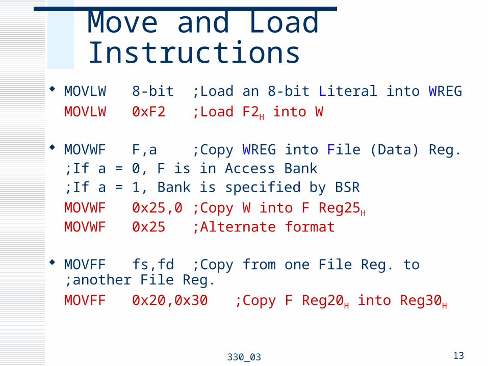
Move and Load Instructions
MOVLW 8-bit ;Load an 8-bit Literal into WREG
MOVLW 0xF2 ;Load F2H into W
MOVWF F,a ;Copy WREG into File (Data) Reg.;If a = 0, F is in Access Bank ;If a = 1, Bank is specified by BSR
MOVWF 0x25,0 ;Copy W into F Reg25H
MOVWF 0x25 ;Alternate format
MOVFF fs,fd ;Copy from one File Reg. to ;another File Reg.
MOVFF 0x20,0x30 ;Copy F Reg20H into Reg30H
13330_03

Move and Load Instructions
MOVF F,d,a ;Copy F into itself or W ;If d = 0 (or W), destination is W ;If d = 1 (or F), destination is F
;Affects N & Z flags
MOVF 0x25,0,0 ;Copy F Reg25H into WMOVF 0x25,W ;Alternate format
CLRF F,a ;Clear F Reg.;Sets Z flag
CLRF 0x25 ;Clear Reg25H
SETF F,a ;Sets all bits to 1 in F Reg.
14330_03

Points to Remember
Each instruction has two parts Opcode and Operand
When instructions copy data from one register to another, the source is not modified
In general, these instructions do not affect flags Except CLRF and MOVF
330_03 15

Arithmetic Instructions
ADDLW 8-bit ;Add 8-bit number to W & set flags
ADDLW 0x32 ;Add 32H to W
ADDWF F,d,a ;Add W to F & set flags;Save result in W if d = 0 (or W);Save result in F if d = 1 (or F)
ADDWF 0x20,0 ;Add W to REG20H and ;save result in W
ADDWF 0x20,W ;Alternate format
ADDWF 0x20,1 ;Add W to REG20H and ;save result in REG20H
ADDWF 0x20,F ;Alternate format
16330_03

Arithmetic Instructions
ADDWFC F,d,a ;Add W to F with carry ;and save result in W or F
SUBLW 8-bit ;Subtract W from literal SUBWF F,d,a ;Subtract W from F SUBWFB F,d,a ;Subtract W from F with
borrow INCF F,d,a ;Increment F DECF F,d,a ;Decrement F NEGF F,a ;Take 2’s Complement of F
17330_03

Arithmetic Instructions
MULLW 8-bit ;Multiply 8-bit Literal and W ;Save result in
PRODH:PRODL MULWF F,a ;Multiply W and F
;Save result in PRODH:PRODL
DAW ;Decimal adjust W for BCD
;Addition
18330_03

Points to Remember
Arithmetic instructions Can perform operations on W and 8-bit literals
Save the result in W Can perform operations an W and F
Save the result in W or F In general, affect all flags
330_03 19

Logic Instructions
COMF F,d,a ;Complement (NOT) F;and save result in W or F
ANDLW 8-bit ;AND Literal with W ANDWF F,d,a ;AND W with F and
;save result in W or F IORLW 8-bit ;Inclusive OR Literal with W IORWF F,d,a ;Inclusive OR W with F
;and save result in W or F
IORWF 0x12,F ;OR W with REG12H and
;save result in REG12H
XORLW 8-bit ;Exclusive OR Literal with W XORWF F,d,a ;Exclusive OR W w/ F
;and save result in W or F
20330_03

Points to Remember
Logic instructions Can perform operations on W and 8-bit literals
Save the result in W Can perform operations an W and F
Save the result in W or F In general, affect only two flags: N and Z
330_03 21

Branch Instructions
BC n ;Branch if C flag = 1, + or – 64 Words;to PC+2+2n
BC 5 ;Branch on Carry to PC+2+10BC Label ;Alternate: Branch to Label
BNC n ;Branch if C flag = 0 BZ n ;Branch if Z flag = 1 BNZ n ;Branch if Z flag = 0 BN n ;Branch if N flag = 1 BNN n ;Branch if N flag = 0 BOV n ;Branch if OV flag = 1 BNOV n ;Branch if OV flag = 0 BRA nn ;Branch always, + or – 512 Words
22330_03

Branch Example
Address Label Opcode Operand Comment
000020 START:
MOVLW BYTE1 ;Load BYTE1 into W
000022 MOVWF REG0 ;Save into REG0
000024 MOVLW BYTE2 ;Load BYTE2 into W
000026 MOVWF REG1 ;Save into REG1
000028 ADDWF REG0,W ;Add REG0 to REG1
00002A BNC SAVE ;Branch if no carry
00002C MOVLW 0x00 ;Clear W
00002E SAVE: MOVWF REG2 ;Save Result
000030 SLEEP
330_03 23

Call and Return Instructions
RCALL nn ;Relative Call subroutine;within + or – 512 words
CALL 20-bit,s ;Call subroutine ;If s = 1, save W, STATUS, BSR
RETURN s ;Return subroutine ;If s = 1, retrieve W, STATUS,
BSR RETFIE s ;Return from interrupt
;If s = 1, retrieve W, STATUS, BSR
24330_03

Points to Remember
Eight conditional relative branch instructions Based on four flags Range is 64 words
Unconditional relative branch instruction Range is 512 words
If the operand is positive, the jump is forward If negative, the jump is backward
330_03 25

Bit Manipulation Instructions
BCF F,b,a ;Clear bit b of F, b = 0 to 7BCF 0x2,7 ;Clear bit 7 of Reg2
BSF F,b,a ;Set bit b of F, b = 0 to 7 BTG F,b,a ;Toggle bit b of F, b = 0 to 7 RLCF F,d,a ;Rotate bits left in F through
;carry and save in W or F RLNCF F,d,a ;Rotate bits left in F
;and save in W or F RRCF F,d,a ;Rotate bits right in F through ;carry and save in W or F RRNCF F,d,a ;Rotate bits right in F
;and save in W or F
26330_03

Points to Remember
Any bit in a File (data) register Set, reset, or complemented
There are two types of rotate instructions 8-bit and 9-bit (include C) Any file (data) register can be rotated left or right
Saved in W or F
330_03 27

Test and Skip Instructions
BTFSC F,b,a ;Test bit b in F and skip the ;next instruction if bit is cleared (bit=0)
BTFSC 0x2,7 ;Test bit B7 in REG2
;if B7=0 then skip next instruction BTFSS F,b,a ;Test bit b in F and skip the
;next instruction if bit is set (bit=1) CPFSEQ F,a ;Compare F with W, skip if F = W CPFSGT F,a ;Compare F with W, skip if F > W CPFSLT F,a ;Compare F with W, skip if F < W TSTFSZ F,a ;Test F, skip if F = 0
28330_03

Increment/Decrement and Skip Next Instruction
DECFSZ F,d,a ;Decrement F and skip the ;next instruction if F = 0
DECFSNZ F,d,a ;Decrement F and skip the ;next instruction if F ≠ 0
INCFSZ F,d,a ;Increment F and skip the ;next instruction if F = 0
INCFSNZ F,d,a ;Increment F and skip the ;next instruction if F ≠ 0
29330_03

Points to Remember
Any File (data) register or single bit in a File (data) register can be tested for 0
A File (data) register can be compared with W for equality, greater than, and less than
A File (data) register can be incremented or decremented and tested for 0
If a condition is met, the next instruction is skipped (no flags are affected)
330_03 30

Table Read/Write Instructions
TBLRD* ;Read Program Memory pointed by TBLPTR;into TABLAT
TBLRD*+ ;Read Program Memory pointed by TBLPTR;into TABLAT and increment TBLPTR
TBLRD*- ;Read Program Memory pointed by TBLPTR;into TABLAT and decrement TBLPTR
TBLRD+* ;Increment TBLPTR and Read Program ;Memory pointed by TBLPTR into TABLAT
31330_03

Table Read/Write Instructions
TBLWT* ;Write TABLAT into Program Memory pointed ;by TBLPTR
TBLWT*+ ;Write TABLAT into Program Memory pointed ;by TBLPTR and increment TBLPTR
TBLWT*- ;Write TABLAT into Program Memory pointed ;by TBLPTR and decrement TBLPTR
TBLWT+* ;Increment TBLPTR and Write TABLAT into ;Program Memory pointed by TBLPTR
330_03 32

Machine Control Instructions
CLRWDT ;Clear Watchdog Timer RESET ;Reset all registers and flags SLEEP ;Go into standby mode NOP ;No operation
33330_03

Instruction Format
The PIC18F instruction format divided into four groups Byte-Oriented operations Bit-Oriented operations Literal operations Branch operations
34330_03

Byte-oriented instruction – ADDWF F, d, aADDWF 0x1,F ;Add W to REG1, save in REG1
Bit-oriented instruction – BCF F, b, aBCF 0x15,7 ;Clear bit7 in REG15H
Instruction Format
35330_03

Literal instruction — MOVLW kMOVLW0x7F ;Load 7FH into W
Branch instruction — BC nBC 0x15 ;Branch if carry +15H words
Instruction Format
36330_03
0

Illustration: Addition
Problem Statement Load two bytes (37H and 92H) in registers REG0 and REG1 Add the bytes and store the sum in REG2
330_03 37
Address Hex Opcode Operand Comments
0020 0E37 MOVLW 0x37 ;Load first byte in W
0022 6E00 MOVWF REG0 ;Save first byte in REG0
0024 0E92 MOVLW 0x92 ;Load second byte in W
0026 6E01 MOVWF REG1 ;Save second byte in REG1
0028 2400 ADDWF REG0,W ;Add bytes and save sum in W
002A 6E02 MOVWF REG2 ;Save sum in REG2
002C 0003 SLEEP ;Power Down

Bus Contents
Execution of theinstruction:MOVLW 0x37
38330_03

Pipeline Fetch and Execution
39330_03
Related Documents